developing web services with serverless architecture
TRANSCRIPT

Lappeenranta University of Technology
School of Business and Management
Degree Program in Computer Science
Master’s Thesis
Trung Hieu Tran
DEVELOPING WEB SERVICES WITH SERVERLESS
ARCHITECTURE
Examiners: Prof. Ajantha Dahanayake
Dr. Antti Knutas
Supervisor: Prof. Ajantha Dahanayake

ii
ABSTRACT
Lappeenranta University of Technology
School of Business and Management
Degree Program in Computer Science
Trung Hieu Tran
Developing Web Services with Serverless Architecture
2017
78 pages, 27 figures, 22 tables and 2 appendixes
Examiners: Prof. Ajantha Dahanayake
Dr. Antti Knutas
Keywords: web services, serverless architecture, serverless computing, cloud computing,
amazon web services
Service-oriented architecture (SOA) and distributed systems have become popular solution
to solve gaps between business needs and Information Technology services. Having widely
adopted as crucial practice of SOA, web services enable communication between software
components or applications over the internet. In this thesis, the author presents an innovative
approach to build web services without concerns about server provision. The approach is
design artefact outputted from the design science process, which consists of serverless
architecture and a practice to implement into web services project. In order to prove the
concept, the serverless architecture and proposed practice are employed to develop a
prototype web service application. Furthermore, the thesis evaluates performance of the
prototype application, in which five test scenarios are setup to examine the application’s
behaviors in various load conditions.

3
TABLE OF CONTENTS
1 INTRODUCTION ....................................................................................................... 8
1.1 EMERGENCE OF SERVERLESS ARCHITECTURE.......................................................... 8
1.2 RESEARCH MOTIVATION ....................................................................................... 10
1.3 THESIS STRUCTURE ............................................................................................... 11
2 RESEARCH METHODOLOGY ............................................................................. 12
2.1 RESEARCH QUESTIONS AND EXPECTED OUTCOMES ............................................... 13
2.2 PHASES OF RESEARCH ........................................................................................... 14
2.3 ADVANTAGES AND DISADVANTAGES .................................................................... 15
2.4 SUMMARY ............................................................................................................. 15
3 LITERATURE REVIEW OF WEB SERVICES ................................................... 17
3.1 TERMINOLOGY AND ORIGIN .................................................................................. 17
3.2 MODEL OF WEB SERVICES ..................................................................................... 18
3.2.1 Conceptual architecture .................................................................................. 18
3.2.2 Development lifecycle ...................................................................................... 20
3.3 ACCESS TO WEB SERVICES: SOAP AND REST ...................................................... 21
3.4 RESTFUL WEB SERVICES ...................................................................................... 22
3.4.1 REST architectural style .................................................................................. 22
3.4.2 Applying to web services .................................................................................. 23
3.5 PERFORMANCE TESTING ........................................................................................ 24
4 INSIGHT INTO SERVERLESS ARCHITECTURE ............................................ 26
4.1 ARCHITECTURE COMPONENTS .............................................................................. 26
4.2 IMPLEMENTATION WITH AMAZON WEB SERVICES ................................................ 28
4.3 DEVELOPMENT PRACTICES .................................................................................... 29
4.4 SUMMARY ............................................................................................................. 32
5 ADOPTION OF SERVERLESS ARCHITECTURE ............................................. 35
5.1 AWS SERVICES AS BACKBONE OF SERVERLESS APPLICATION ............................... 35
5.1.1 AWS Lambda function ..................................................................................... 35
5.1.2 API Gateway .................................................................................................... 37
5.2 SOURCE CODE CONTROL AND OTHER TOOLS ......................................................... 40
5.3 CODING PROTOTYPE APPLICATION ........................................................................ 41
4
5.3.1 Database .......................................................................................................... 41
5.3.2 Project structure .............................................................................................. 41
5.3.3 Dependencies management and installation ................................................... 43
5.3.4 API resources ................................................................................................... 44
5.3.5 Business logic code .......................................................................................... 47
5.4 APPLICATION BUILD AND DEPLOYMENT ................................................................ 49
5.5 MONITORING AND MAINTENANCE ......................................................................... 52
5.6 SUMMARY ............................................................................................................. 55
6 TESTING SERVERLESS PROTOTYPE APPLICATION .................................. 57
6.1 MUTUAL TESTING CONFIGURATION ...................................................................... 57
6.2 GROUP A - SCENARIO 1 ........................................................................................ 59
6.3 GROUP A - SCENARIO 2 ........................................................................................ 60
6.4 GROUP B - SCENARIO 3 ......................................................................................... 62
6.5 GROUP B - SCENARIO 4 ......................................................................................... 64
6.6 GROUP B - SCENARIO 5 ......................................................................................... 66
6.7 SUMMARY ............................................................................................................. 69
7 CONCLUSION .......................................................................................................... 71
7.1 FINDINGS AND DISCUSSION ................................................................................... 71
7.2 RESEARCH LIMITATION AND FURTHER RESEARCH SUGGESTION ............................ 73
APPENDIX ......................................................................................................................... 79

5
LIST OF TABLES
Table 1. Search results of scientific papers based on keywords [22] .................................. 11
Table 4. Major metrics of performance testing [40] ............................................................ 25
Table 5. Reflection of guidelines ......................................................................................... 33
Table 6. Project dependencies summary .............................................................................. 43
Table 7. Summary of prototype application ........................................................................ 56
Table 8. Configuration elements [56] .................................................................................. 57
Table 9. Stats in load test’s report [57] ................................................................................ 58
Table 10. Scenario 1 - Test configuration and summary ..................................................... 59
Table 11. Scenario 1 - All endpoint’s results ....................................................................... 59
Table 12. Scenario 2 - Test configuration and summary ..................................................... 60
Table 13. Scenario 2 - All endpoint’s results ....................................................................... 61
Table 15. Scenario 3 - All endpoint’s results ....................................................................... 63
Table 16. Scenario 4 - Test configuration and summary ..................................................... 65
Table 18. Scenario 5 - Test configuration and summary ..................................................... 67
Table 19. Scenario 4 - All endpoint’s results ....................................................................... 67
Table 20. Number of requests and errors in all tests ........................................................... 69

6
LIST OF FIGURES
Figure 1. Phases of research and timeline ............................................................................ 14
Figure 2. Web services architecture [8] [26] ....................................................................... 19
Figure 3. Development lifecycle of web services [8] [31] .................................................. 21
Figure 4. Major components of serverless architecture ....................................................... 27
Figure 5. AWS services supporting serverless architecture ................................................ 29
Figure 6. Continuous development workflow adopted ........................................................ 31
Figure 7. Major configurations of Lambda function ........................................................... 36
Figure 8. Test invocation of Lambda function .................................................................... 37
Figure 9. Sample endpoint in API Gateway on AWS management console ....................... 38
Figure 10. Test API call on AWS console ........................................................................... 39
Figure 11. API requests demonstration ................................................................................ 40
Figure 12. Components and project structure ...................................................................... 42
Figure 13. Installation of software dependencies ................................................................ 44
Figure 14. Configuration of first API .................................................................................. 45
Figure 15. Configuration of actor endpoints ........................................................................ 46
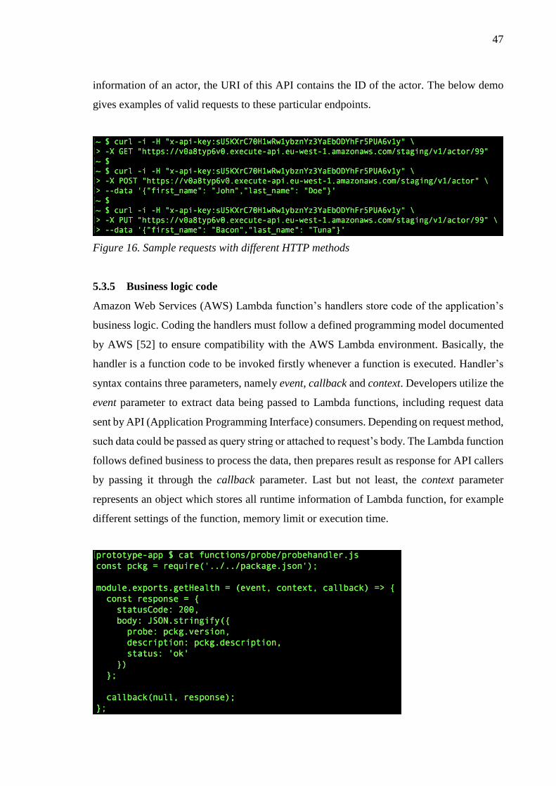
Figure 16. Sample requests with different HTTP methods ................................................. 47
Figure 17. Function probeGetHealth handler ...................................................................... 48
Figure 18. Code to retrieve data from requests .................................................................... 48
Figure 19. Insight into build and deployment pipeline ........................................................ 50
Figure 20. Failure versus success in deployment pipeline ................................................... 52
Figure 21. Graphed metrics of API requests ........................................................................ 53
Figure 22. Logs of Lambda functions on CloudWatch ....................................................... 54
Figure 23. Scenario 1 - Timeline report ............................................................................... 60
Figure 24. Scenario 2 - Timeline report ............................................................................... 62
Figure 25. Scenario 3 - Timeline report ............................................................................... 64
Figure 26. Scenario 4 - Timeline report ............................................................................... 66
Figure 27. Scenario 5 - Timeline report ............................................................................... 68

7
LIST OF SYMBOLS AND ABBREVIATIONS
API(s) Application Programming Interface(s)
AWS Amazon Web Services
CPU Central Processing Unit
CRUD Create, Read, Update, Delete
FaaS Function as a Service
HTTP Hypertext Transfer Protocol
I/O Input/Output
IT Information Technology
REST Representational State Transfer
S3 Amazon Simple Storage Service
SOA Service-Oriented Architecture
SNS Amazon Simple Notification Service

8
1 INTRODUCTION
1.1 Emergence of serverless architecture
Service-oriented architecture (SOA) has become mainstream and prime discipline to address
the gap between business services and Information Technology (IT) services [1]. Over the
last decades, SOA and distributed systems are developed by enterprises to serve various
business domains, from letter mail, logistics to finance and banking services [2]. The
fundamental of SOA is to release independent and self-describing software components
which are universally available and accessible over a network via standard communication
protocols [3]. As a major implementation, web services technology has adopted this concept
in building modern web applications [4] [5].
For years, web applications have been developed based on a three-tier architecture that views
an application as three independent layers, namely presentation, business logic, and data [6].
Basically, the architecture defines the separation of concerns among frontend (the display of
data and interaction with users), data sources (the persistent storage of application’s data),
and backend (the mediates between frontend and data sources that handles business logic)
[6] [7]. The decoupling concept allows developers to implement significant changes in a
layer without influencing the other tiers, and hence of easily maintainable software.
Meanwhile, from the perspective of SOA design, business logic and data layers can be
implemented as web services, enabling communication via standard internet-based protocols
[5]. Recently, web services publish APIs (Application Programming Interfaces) to instruct
their consumers how to establish connection and exchange data [8]. The popular
implementations of web services access are SOAP (Simple Object Access Protocol) [1] and
REST (Representational State Transfer) [9].
A web service is deployed and served by web server, which is a software running on physical
or virtual machine [10] [11]. The web server provides data transportation through HTTP
(Hypertext Transfer Protocol) that listens and returns HTTP requests and responses,
respectively [8]. As being hosted on a physical or virtual machine, there are requirements
for configuration and maintenance works. Development team must study and decide
specifications for the machine (such as processor speed, memory, and storage spaces) to
obtain an adequate resource for server to run the web service. If server is built in-house, the

9
process would include procurement of hardware components and software licenses, as well
as time and team’s effort to setup. Additionally, such web server needs regular maintenance
that requires human resources, for example monitoring to check errors, executing rational
plans to address incidents (server is occasionally overloaded or crashed), and upgrading the
system (both software and hardware components) [12]. On the other hand, web services can
be deployed on computing platform, in which cloud vendors provide necessary
infrastructures and computational resources to host and run applications [11] [13]. Having
employed this approach, the team discards concerns about hardware components, however,
the works of server and operating system configuration, monitoring and maintenance are
still persistent and require human efforts [11].
Recently, cloud vendors (such as Amazon [14], Google [15], IBM [16]) have introduced
serverless computing services, also known as Function-as-a-Service (FaaS) [17]. For
instance, the computing services developed by Amazon, namely AWS (Amazon Web
Services) Lambda, provides an ephemeral function’s container for executing application’s
code [18]. The container is a fully configured environment that is compatible with running
such source code. Therefore, the team can concentrate on writing back-end code for business
logic and deploying to such platforms without concerning the complexity of building and
maintaining infrastructure. Moreover, and more especially, function code is invoked on
request, leading to remove traditional “always on” server system running behind the
application [19]. This idea contributes to an emerging approach to develop web services,
namely serverless architecture, in which web services are built, deployed and distributed on
cloud environment with zero provisioned server [17].
To clarify, serverless architecture carries a disclaimer; despite its name, the approach does
not declare the involvement of servers. In fact, there are servers that are setup and managed
by cloud service vendors. The term “serverless” is used from the perspective of
development teams, in which they do not purchase, rent, maintain either servers or virtual
machines to run application’s code. Instead, they are charged for actual computing resources
consumed to execute the code. To put it differently, there is no cost if the code is not running.
Thus, to some degree and in some circumstances, the approach of serverless architecture
helps reduce operational costs in comparison with the traditional solution of constantly
keeping a running server.

10
1.2 Research motivation
In mid-November 2014, Amazon introduced Lambda function on their Amazon Web
Services (AWS) - an event-driven and computing platform [14]. The platform allows code
to be executed in response to events without provision of servers or compute resources.
Together with the launch of API (Application Programming Interface) Gateway, AWS
Lambda has led to the concept of serverless architecture. Since last two years, serverless has
become a rising topic in the world of software architectures. Yet, the community has
witnessed its emergence with several open-source frameworks [20] and dedicated
conferences [21].
Meanwhile, Amazon API Gateway provides a fully-managed cloud-based environment for
building, releasing and maintaining APIs [18]. To be specific, it acts as entrance for
applications to connect with business logics, functionalities or retrieve data from other AWS
services. Code running on AWS Lambda can be certainly invoked by sending requests to
API Gateway, enabling possibility to develop a complete web service. Therefore, AWS has
provided adequate infrastructure to create web services without any concerns about servers
(physical or virtual) configuration and monitors.
In addition to Amazon, several vendor products are introduced to support development of
serverless applications. Among them, IBM and Google are big names showing their interests
in this area. Similarly, Bluemix OpenWhisk has announced by IBM in the early 2016,
offering an alternative for serverless computing platform [16]. On the one hand, as an answer
to AWS Lambda, Google supplemented their Cloud Platform by launching Cloud Functions
product [15]. As such, the serverless concept has gradually been in spotlight, in which there
are diverse options for development platform offered by prestigious providers.
Moreover, in the software companies, there is a need for web services in which can be
developed rapidly, highly scalable, and require insignificant maintenance effort. Since the
announcement of AWS Lambda and API Gateway, the idea of employing them had been of
utmost interest. However, a raising question has been how to implement efficiently and
organize versioning of source code in the context of continuous integration and deployment.

11
In addition, having reviewed some of the literature about software architectures, specifically
in web applications and services, it is worth mentioning that there is a lack of reports and
research about practice of emerging serverless architecture. Yet, the author searches for
research paper relating to keywords of web services architecture, cloud services, serverless
architecture, and serverless application. The below table illustrates and compares the results
found in different scientific databases [22], in which the number of articles concerning
serverless architecture is minor. Therefore, it encourages the author to conduct a study to
find a possible practice to adopt serverless architecture into developing web services.
Table 1. Search results of scientific papers based on keywords [22]
Keywords Science Direct IEEE Explorer Emerald Springer
Web services 28532 results 20750 results 17712 articles
360 case studies 28114 results
Web services
architecture 13757 results 5639 results
5914 articles
52 case studies 52849 results
Cloud services 12091 results 20581 results 5066 articles
75 case studies 57098 results
Serverless
architecture 35 results 8 results 2 articles 77 results
Serverless
application 43 results 14 results 3 articles 118 results
1.3 Thesis structure
The thesis begins with introduction in Chapter 1, briefly telling the emergence of serverless
architecture, motivation of this research, and this thesis structure. In Chapter 2, the author
presents the research methodology, including research approach, research questions,
objectives, as well as advantages and disadvantages of the study. Following the research
design of this thesis, Chapter 3 covers the literature review part. The chapter reviews web
services concept and performance testing methods for web services. Afterwards, in Chapter
4, the author provides readers with an insight into the serverless architecture and its
development practice. They are also discussed in regard to the adoption of serverless
architecture into building web services on a specific cloud provider - Amazon Web Services.
Chapter 5 consists of discussion and explanation about detailed implementation of a

12
prototype web application, which is a proof-of-concept of the serverless architecture.
Continuing with Chapter 6, the author conducts performance testing activities to evaluate
the prototype application developed in previous chapter. They consist of different test
scenarios that have distinct configurations to diversely examine the application’s behaviors.
Finally, Chapter 8 appears to make summary for the whole thesis. It concerns answers of the
research questions arising in beginning of the research and discussion about findings. In
addition, limitations of this study as well as further work possibilities are also mentioned.

13
2 RESEARCH METHODOLOGY
2.1 Research questions and expected outcomes
The research attempts to address problems of software company, expecting rapid
development of web services with less concerns about maintaining works. As such, the
research is mainly to experiment and design a possible practice to adopt the serverless
architecture. The solution includes technical implementation fitting the practices of
continuous development, efficient workflow, and deployment process. The newly generated
solution can be applied in real-world software projects, where its efficiency and effect can
be verified. There are two major research questions (RQ) that are targeted to answer:
• RQ1: What are main components of serverless architecture?
• RQ2: What is the development practice of serverless architecture?
The expected deliverables of this research are an artifact, the design of serverless architecture
implementation, and a test to prove its feasibility. The build of artifact design is two-fold,
which is based on working experience and background knowledge extracted from different
scientific works. Such scientific works are obtained by doing literature review of relevant
topics, including software architecture, web services, and available development processes,
tools and techniques. The proof-of-concept of serverless implementation is delivered by a
construction of rough prototype that implements the serverless architecture. Development
practices in the context of continuous integration with involvement of multiple developers
are put into consideration. The prototype is also benchmarked to check whether its
performance is acceptable. This research will use the design science framework to validate
the artifact [23].

14
2.2 Phases of research
March and Smith [24] indicated that outputs of design science are innovative and valuable
constructs, models, methods and implementations. Those artifacts result from two basic
activities of building and evaluation. Accordingly, this research targets at producing an
artifact which is an implementation (a possible practice to develop application with
serverless architecture). To fulfill the above, the research can consist of phases and activities
which are presented in the following figure. To be noted, the time frame is estimated and
subject to change.
Figure 1. Phases of research and timeline
Design science’s activities are twofold, consisting of two factors: build and evaluate. The
build phase refers to artifact’s creation to solve real problems. Within this phase, literature
review is conducted to study the possibility of adopting serverless architecture.
Consequently, a solution is generated and addresses the following problems:
• Components of a serverless application
• Development process and workflow
• Deployment practice in the context of continuous development

15
In the evaluate activity, an application prototype is developed to prove the feasibility of
serverless architecture. The application is benchmarked against selected criteria to test its
performance in laboratory environment. At the third phase, output of the artifact will be
comprehensively discussed to theorize an approach of serverless architecture into
developing web services. Finally, within the last phase of justifying, an empirical study will
be conducted to examine the research output in real-world application development.
2.3 Advantages and disadvantages
The research concerns cloud computation, where majority of development activities,
application deployment, and evaluation are conducted. There are several applicable cloud
computing vendors on the market as listed in the introduction chapter. Among them, Amazon
is the provider of choice for three main reasons. First, this research is conducted with
working experience in the AWS cloud environment that helps boosting up the research
progress. Second, Amazon is the pioneer of providing necessary services for building
serverless applications, and hence of adequate experiences in troubleshooting and support.
Finally, Amazon offers a free tier program to access AWS cloud products at reasonable cost,
fitting purpose of experiment and budget.
In addition, the implementation is mainly done using Node.js and JavaScript programming
language, which is applicable to the model of event-driven and non-blocking I/O. As such,
the research is limited to this programming language and its relating technologies. The
research does not put database design into consideration so that database technologies are
not mentioned. Also, the information security is excluded from the study. As the
implementation is done on the AWS, the author delegates this duty to the provider. In fact,
Amazon’s highest priority is to build security-sensitive data center and network architecture
for customers [25]. Thus, the implementation can be conducted with confidence in a secure
cloud environment.
2.4 Summary
To sum up, the advantages and limitations that this research suffers from can be listed as
following:

16
Advantages
• Hands-on experiences in Amazon Web Services (AWS)
• Choice of the pioneering provider with rich capability of support
• Highest priority of the provider on security
• Reasonable cost that fitting the research’s budget
Disadvantages
• Only AWS and their services are concerned, leading to the falsifiability of result in
other providers
• Implementation language and technologies
• No database designs

17
3 LITERATURE REVIEW OF WEB SERVICES
3.1 Terminology and origin
Web service is widely admitted as a crucial practice of service-oriented architectures,
enabling communications between software components or business applications over the
internet [5] [26]. As different software or applications are implemented with different
programming languages, hardware and platform, specifications of a web service are totally
independent of them to provide a standard and universal method of data exchange [26]. In
other words, the fundamental is that no knowledge of consumers is required to develop a
web service, and vice versa. This also facilitates easy and quick integration of existing
software solutions and development of distributed applications [5]. In addition, Fensel et al.
[26] indicated the six basic principles that describe the common definitions and
characteristics of web service, which is briefly illustrated in the following table.
Table 2. Basic principles of web service [26]
Loose coupling Service is stateless, accessible, not tightly coupled to consumers and
to its logic and implementation.
Contracted Contract represents a service, defining its inputs, outputs, access
policies, quality requirements, and error-handling procedures.
Discoverable Service is discoverable at execution time.
Addressable Service is uniquely identifiable in a network.
Distributed As being separated by geographic and machine boundaries, service is
capable for addressing loss of communication.
Point-to-point A consumer uses only one producer at any point in time.
To some extent, web service can be viewed as a middleware solution, in which it defines the
communication protocols and digital rules for exchanging data messages [26]. In the history
of computer science, the attempts to create universal standards for development of
distributed applications resulted into middleware solutions. They act as an abstraction layer,
serving as interface for the actual communications and data exchanges between application’s
components [27]. Remote Procedure Calls (RPC), introduced and widely used in the early

1 World Wide Web Consortium: an international community that works to define web standards 2 Uniform Resource Identifier (URI): a string of characters to identify a resource
18
1980s, was recognized as the very first middleware solution to remotely invoke procedures
in a distributed system. The RPC technology acts as a layer covering implementation details
from developers to provide a mechanism, which is decoupled from platform and
programming language, to execute distributed procedure calls [28]. After years of
advancement, different middleware techniques and architectures were introduced, such as
extensions of RPC - remote method invocation or message-oriented middleware [29], and
CORBA architecture [30]. Notwithstanding that, they failed to achieve the expected goal of
an effective and simple communication gateway, and hence of limited use. Therefore, web
service technologies were born to solve such problem, in which their emergence has solved
existing problems, showing many pros over the predecessors, and being widely adopted for
a long-term success [26].
To sum up, the W3C1 agreed on a general working definition of a web service as following:
“A Web service is a software application identified by a URI2, whose interfaces and bindings
are capable of being defined, described, and discovered as XML artifacts. A Web service
supports direct interactions with other software agents using XML-based messages
exchanged via Internet-based protocols.” [5]
3.2 Model of web services
As discussed in the above section, basically, web services enable remote access to functions
via the internet by utilizing a set of standards. The key methodology is to provide developers
a mean of data communication and exchange which is free from the concerns towards
programming language and operating system. Within this section, the conceptual
architecture and development lifecycle of a web service will be discussed.
3.2.1 Conceptual architecture
Kreger [8] indicated three roles in a web service, namely service provider, service requester
and service registry. First, service provider is considered as the owner of a web service,
hosting access to that web service and making it available on the internet. The provider
listens for requests, processes them, and provides data to send back. On the other hand,
service requester is used to identify consumers of a web service. They may be a web browser
driven by an individual or other available web services. Such consumers produce different

19
interactions with the web service based on their needs, for instance asking for data by sending
requests to the provider. Third, service registry is a logically centralized storage of all service
descriptions where existing services can be found and newly implemented ones are added.
The following figure depicts this fundamental architecture of web services, from which three
major building blocks based on these roles can be discovered.
Figure 2. Web services architecture [8] [26]
Service and service description are two artifacts, in which a service is a software module
deployed on platform of service provider. The module is accessible so that it can be invoked
by a service requester. In many cases, a service can be implemented as a requester that
interacts with other web services. Meanwhile, service description is published to service
provider, service registry or both, containing comprehensive information about service’s
interface and implementation. The information consists of data types, operations, invocation
instructions, service’s location on network, and possibly necessary meta-data to facilitate
utilization by its consumers. [8].
Correspondingly, there are three operations of “publish”, “find” and “invoke”. A service
must be published together with its description so that service requester knows how to find
it [26]. Depending on requirements and design, the service is published on either production
20
or development environment, and publishing plan is also included. The “find” operation
discusses discovery of the service from service requester’s perspectives, in which details
about service descriptions and how to use them are acquired. Eventually, a service needs to
be invoked by the requester, and this refers to the “invoke” operation. By utilizing the “find”
operations, the service requester can find the service’s location and establish interactions.
[8].
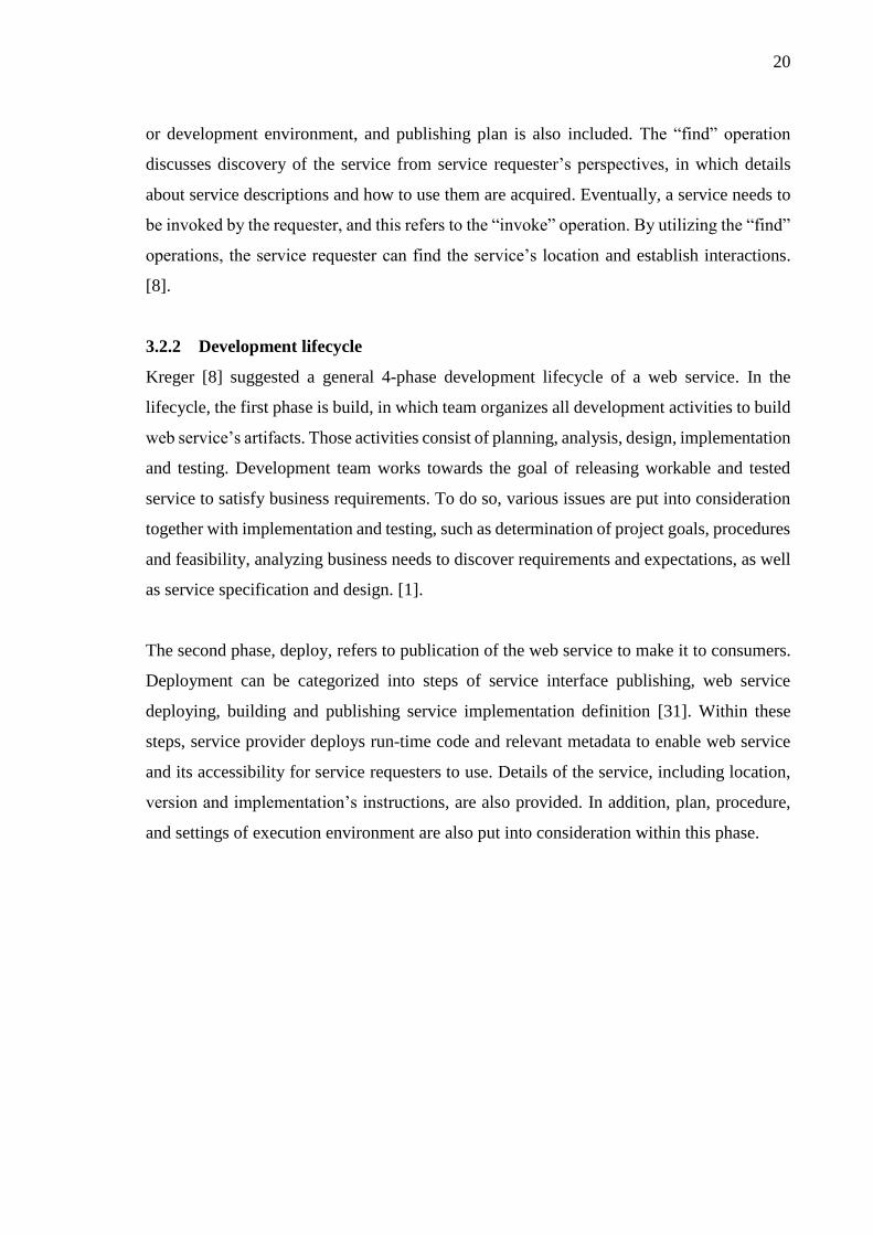
3.2.2 Development lifecycle
Kreger [8] suggested a general 4-phase development lifecycle of a web service. In the
lifecycle, the first phase is build, in which team organizes all development activities to build
web service’s artifacts. Those activities consist of planning, analysis, design, implementation
and testing. Development team works towards the goal of releasing workable and tested
service to satisfy business requirements. To do so, various issues are put into consideration
together with implementation and testing, such as determination of project goals, procedures
and feasibility, analyzing business needs to discover requirements and expectations, as well
as service specification and design. [1].
The second phase, deploy, refers to publication of the web service to make it to consumers.
Deployment can be categorized into steps of service interface publishing, web service
deploying, building and publishing service implementation definition [31]. Within these
steps, service provider deploys run-time code and relevant metadata to enable web service
and its accessibility for service requesters to use. Details of the service, including location,
version and implementation’s instructions, are also provided. In addition, plan, procedure,
and settings of execution environment are also put into consideration within this phase.

21
Figure 3. Development lifecycle of web services [8] [31]
Third, in the run phase, the web service is completely deployed and available over the
network to use. Service requestor can perform the “find” and “invoke” operations [8].
Finally, once the service is operational, it comes to the manage phase which contains
administration, maintenance and evaluation of the web service application. The purpose is
to monitor its performance within the operational environment to determine whether the
business processes, quality and cost are sufficiently addressed [1]. As such, measurable data
are collected and different metrics are extracted from them to assess the service
correspondingly to specific needs. For instance, information about service response time, up
and down times or throughput can be recorded [1].
3.3 Access to web services: SOAP and REST
SOAP (Simple Object Access Protocol) and REST (Representational State Transfer) are two
implementations used for accessing to web services [1]. Having developed by Microsoft
since 1998, SOAP relies on XML-based mechanism to transport structured data between
network applications [32]. SOAP messages consist of three elements: envelope, header, and
body, and can be transported via a wide range of network protocols, such as HTTP, SMTP
or FTP [8] [1]. A mandatory envelope, which is parent element of header and body, defines
start and end of a message to let receiver know whether the message is completely received
and can be processed. Header is an optional element describing a set of encoding rules for

22
additional application-defined requirements, for example, a digital signature can be included
to tell receivers how to access password-protected web service. Meanwhile, body is required
element that contains information about service’s calls, responses, and XML data being
exchanged [8].
In his doctoral dissertation published in 2000, Fielding introduced REST (Representational
State Transfer) as an alternative architectural style to provide interoperability between
network applications [33]. REST (or RESTful web services) was born to solve the problems
of limited scalability, complexity and performance of existing protocols [34]. It targets at
reducing network latency, boosting the independence and scalability of component
implementations. An insight into this modern web architecture will be presented in the
following sub-chapter as this thesis is mainly concerned with implementing RESTful web
service.
3.4 RESTful web services
3.4.1 REST architectural style
The fundamental of REST consists of three main concepts, namely resource, representation
and state [35]. A resource can be any information (for instance document, image, temporal
service, or collection of other resources) which is located on a computer and represented as
bit stream. To distinguish resource in an interaction between components, a resource
identifier is employed. Representation contains useful metadata around a resource at any
timestamp to help clients in transition within resource’s states. Representation is exposed to
many-to-one relationship with the resource. Meanwhile, there are two types of state in REST
architectural style: resource state and application state. Basically, resource state is
information about a resource and handled by server, whereas application state maintained
by client refers to information about where it in interaction with server.
REST concentrates on data element, their interpretations and interactions between different
application’s components instead of implementation details and protocol syntax [35]. In fact,
REST ignores them to lose coupling of such components. As such, a guideline set of six
architectural constraints is included to promote the scalability, generality of interfaces, and
independent

23
Table 3. Six architectural constraints of REST [33] [35]
Client - Server Separation of concerns: data storage and interface
Stateless Server doesn’t store client context between requests
Cacheable Response defined as non- or cacheable to prevent data reuse,
increase efficiency
Uniform interface
constraints
Increase visibility of interactions and reuse of resources and
services
• Resource-based (HTML, XML, JSON)
• Manipulation of resources (how to modify resource)
• Self-descriptive messages (how to process message)
• Hypermedia (request and response techniques)
Layered system
Intermediary servers for
• Scalability (load balancing, shared caches)
• Security policies
Code on demand
(optional) Executable code (applets or scripts) to extend client’s functionality
3.4.2 Applying to web services
Embarking the above six architectural constraints, web service APIs are considered as
RESTful APIs which also have the following aspects:
• Base URL: a short string to identify a resource that associates with a protocol to
obtain representation of the resource [9].
• Media type: exchanged data are described by media type, in which state transition
of data elements are included to instruct clients to prepare requests for next available
application states. For instance, a media type can be text/html, which means an
HTLM document. Common media types are textual documents (text/html),
structured data documents (application/json, application/xml), and images
(image/png, image/jpeg). [9] [36]
• Standard HTTP methods: client use such methods to instruct server on what to do
with data. The most popular ones are GET (retrieve data), POST (save new data),
PUT (update existing data), DELETE (remove existing data) and HEAD (identical
to GET but without response body) [9].

24
At basic scope, many RESTful web services equip client applications with CRUD interfaces
(create, retrieve, update, delete) to interact with underlying databases. Notwithstanding that,
deducing from the architectural style and constraints, REST is not limited to such CRUD
services, but also feasible for rich state applications, such as flight and hotel reservation
systems, or foreign currency exchange systems [37]. Taken a hotel reservation application
as an example, a user makes a booking on the system but has not paid yet, as such the
resource state is marked as active and unpaid. Once payment resource is invoked, the service
is proceeded to state of processing payment, from which either confirmed or unpaid state
will be next, correspondingly to successful or failed payment [38]. In the real world, many
various states can be also considered, such as free or conditional cancelation of booking,
later payment, and booking change.
3.5 Performance testing
Web services have been widely adopted by companies and enterprises to build web-based
applications to support various aspects of social life [4] [39]. In the meantime, development
community have paid more attention to the concerns over reliability and accuracy of web
services [40]. Performance of web applications are therefore tested to evaluate its capacity
for serving consumers. In details, performance testing is done by gathering information
regarding to operations of applications, and analyzing those collected data to understand its
behaviors and ability to process heavy workloads [41]. The analysis eventually comes to
forecast whenever application runs out of resources to handle consumer’s requests, and
hence of detecting performance issues. Furthermore, the application’s efficiency and
optimization are also justified. Subsequently, performance testing results are utilized to
figure out possible fixes to improve in subsequent releases [40] [42].
The fundamental of performance testing is to simulate end user’s requests to a web
application and study responses under different user loading conditions. By simulation, test
generator defines virtual users, perform repeatedly user’s requests to create high traffic flow
to the application [41]. There are three types of web performance testing, namely stress
testing, load testing, and strength testing, in which they are done by gradually increases
system load to web application [40]. Stress or pressure test aims at analyzing current
configuration and compatibility between hardware and software at maximum load to figure
25
out possible system bottlenecks. Loading test targets at determining application’s capability
by examining maximum load condition that the application can stand. Load test and stress
test can be executed in conjunction. In contrast, strength test is performed in considerably
longer duration (for hours or days) to investigate inexplicable bugs that are not easily
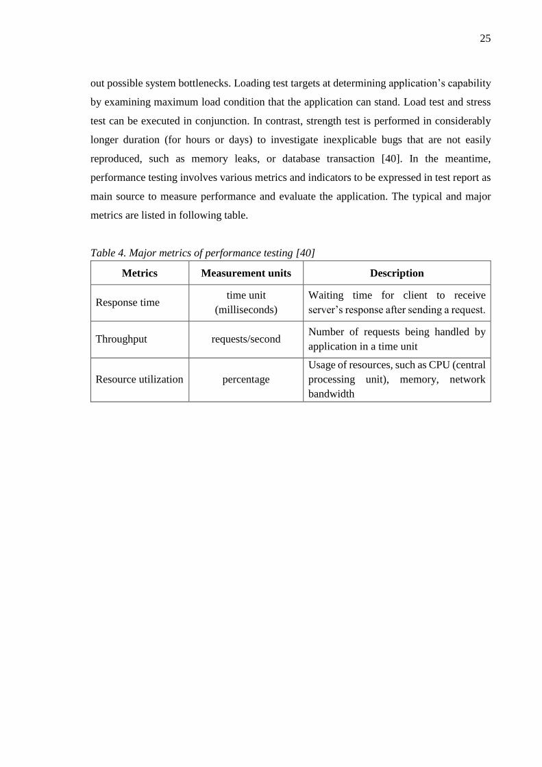
reproduced, such as memory leaks, or database transaction [40]. In the meantime,
performance testing involves various metrics and indicators to be expressed in test report as
main source to measure performance and evaluate the application. The typical and major
metrics are listed in following table.
Table 4. Major metrics of performance testing [40]
Metrics Measurement units Description
Response time time unit
(milliseconds)
Waiting time for client to receive
server’s response after sending a request.
Throughput requests/second Number of requests being handled by
application in a time unit
Resource utilization percentage
Usage of resources, such as CPU (central
processing unit), memory, network
bandwidth

26
4 INSIGHT INTO SERVERLESS ARCHITECTURE
The fundamental goal of design science research process is to solve problem by creating new
knowledge [43]. Solutions are acquired through the understanding of the problem and also
based on existing knowledge. They are acquired and captured in the form of viable artefacts
[24]. In their published articles, Hevner et al. [23] insisted in the guidelines of design science
research that outcome of the process must be purposeful artifact in the form of a construct,
model, method or instantiation. In addition, the artifact is problem-specified that addresses
a problem domain. Therefore, within this chapter, the author is going to present and explain
about the design artefacts in this research.
4.1 Architecture components
Components of serverless architecture are serverless computing platform, API (Application
Programming Interface) container, system operation monitoring tool, database and other
supplement services. These components are different services provided and maintained by
cloud service vendor. Among them, computing platform executes application code to handle
business logic, including database access and manipulation. Meanwhile, APIs container is
responsible for managing application’s REST (Representational State Transfer) API in terms
of publishing all API endpoints, controlling access, and monitoring traffic. Monitoring tool
(or logging system) collects relevant data and information regarding to application’s
operation and ensures its availability. Last but not least, depending on business requirements,
supplement services, such as e-mailing, location tracking, data storage and analytics, can be
integrated into the application.

27
Figure 4. Major components of serverless architecture
The above figure illustrates such major components of the serverless architecture. A request
to application is done through API call, which first goes to API container. The container
checks whether this call is authorized, and extracts data that being sent in the body or query
parameters. Subsequently, corresponding functions in computing platform are invoked to
continue processing the request. The functions execute business logic with input data,
establish connection with database to retrieve or manipulate data records if necessary, then
prepare a response to send back to the requester. In the meantime, detailed information
relating to the process are traced and logged into the operation monitoring tool. By such,
they are available to be retrieved for investigation in case of incident. Furthermore,
monitoring tool should be able to track and store operation data caused by any supplement
services being integrated into serverless application.
28
4.2 Implementation with Amazon Web Services
As mention in chapter one, Amazon is the pioneer providing compatible services as well as
infrastructures for implementing serverless architecture. In their AWS cloud environment,
the backbone services employed to develop serverless application are AWS Lambda
functions and API Gateway. AWS Lambda is serverless computing platform, which serves
as an ephemeral container with suitable software dependency to execute functional code
without server provision [19]. In other words, developers need to only concentrate on writing
and testing code for application’s backend services while the whole computing infrastructure
is managed by AWS Lambda. Meanwhile, the fully-managed Amazon API Gateway helps
developer publish and maintain APIs, acting as front door to call backend service located on
AWS Lambda [18]. API Gateway is bundled with management and monitoring tools to
version the APIs, authorize access as well as audit the traffic. On the other hand, in terms of
database engines, Amazon equips developers with different solutions for both relational (for
example PostgreSQL, Oracle, Microsoft SQL Server, or MySQL) and non-relational
databases (such as NoSQL) [18]. In cooperation with these backbone services and database
services, there are also other AWS services to not only bring more added value to the
application but also play key role in managing the its operation. The following figure visually
summarizes major AWS services to support serverless architecture and their relations.

29
Figure 5. AWS services supporting serverless architecture
Logs and logging management system are organized with Amazon CloudWatch - a
monitoring service for resources and applications running on the Amazon cloud environment
[18]. CloudWatch gathers detailed information relating to operations of Lambda functions.
It also provides useful metrics, configurable alarm settings to notify stakeholders whenever
failing, and various filters to quickly search for correct logs [44]. Many other systems, for
instance e-mailing, phone calling, or data storage, can be integrated in order to fulfill certain
business needs. Fortunately, AWS offers a wide range of supplement services to fit various
requirements, for example Simple Storage Service (S3) to serve as highly-scalable data
object storage, Simple Notification Services (SNS) to support sending email or phone
messages.
4.3 Development practices
In the world of agile software development, continuous integration and delivery is major
strategy for building and releasing software. The methodology encourages developers to
push new code more frequently on daily basis [45], which should be adopted into practice

30
of serverless architecture. To be specific, each update triggers an automated process to verify
such code update by attempting to build the whole code base. In addition, the process also
executes a test set, which may consist of unit tests to check small pieces of functional code
and integrations test to demonstrate if individual software components work as expected. As
long as the code base can be successfully built and passed certain tests, the integration
process is considered completed and ready to deliver. In a word, by early verifying changes
of the software, continuous integration is to increase the possibility to detect errors soon
[46]. Meanwhile, the goal of continuous delivery is to ship newly-updated version more
regularly to quality assurance teams to perform testing activities. As such, it helps team
respond faster to requirement changes and reduce time to market of the software, hence of
saving resources [47].

31
Figure 6. Continuous development workflow adopted
In software development project, there are many developers involving in the process. They
write code and contribute to common repository, then continuous integration (CI) tool builds
the application from such code base and tests it. Successful builds are deployed to the cloud
where application is available to serve users. In order to guarantee workable release, the

32
author utilizes separate CI jobs to deploy application to isolated, which can be named as
staging (or testing) and production. Staging is a replica of production environment so that
development team can safely test the application against its business as well as performance
requirements without affecting real customer’s traffic.
Notwithstanding that, developers do not push code changes directly to deploy on staging
environment. Main reason is to minimize possible application break that interrupts testing
activities from other members, and hence of unproductivity. As a convention, developers
create new function of the software and commits code to a feature branch of the code
repository. The convention requires every new feature to be separately built on isolated code
branch. Then, other developers must review and approve changes prior to merge into develop
branch, which means to be ready for deployment to staging environment. Once application
is tested and verified with updates, development team releases a version of the software for
production users. It is done by merging the develop branch into master branch, subsequently
triggering the build and deployment process to production environment. Furthermore,
another release practice can be adapted, in which successful build version running on staging
can be promoted to production environment. After that, developers proceed to merge
develop into master branch to archive and finish release process. In this thesis, the author
employed the first approach in developing the prototype application in the chapter 5.
4.4 Summary
Following the guidelines by Hevner et. all [23], output of a design science research is design
artefact to solve a business problem. To be reflected in this thesis, the result artefact (figure
4) is delivered in the form of model with the purpose of promoting an approach to develop
web services without server provision. In details, it consists of the serverless architecture
(figure 4) and a practice (figure 6) to implement into web services application development
project. This design artefact is a technology-oriented, equipping technical audiences with an
innovative approach to develop web services application. The serverless architecture relies
on a computing platform and other on-demand cloud services which allows developers to
execute software function’s code without infrastructure provision. The main idea is to shift
concerns about backend infrastructure from in-house to cloud vendors so that development
team can utilize benefits of cloud computing, and concentrate on writing application’s code.

33
Yet, all necessary computing resources and configuration can be set and flexibly adjusted
according to application’s actual loading demands and scalability needs. In other words,
cloud providers are responsible for doing infrastructure setup and maintenance running
behind such cloud services. It does not require developers to setup physical or virtual
machine, install operating system and necessary software to configure server and
environment for applications. The developers are also free from mandatory maintenance
works, including hardware procurement, upgrade or software patches to ensure uptime of
machine and application as well.
Table 5. Reflection of guidelines
Guidelines [23] Thesis
Design as an artefact
(research’s outcome)
- Serverless architecture
- Development practice
Problem relevance
(solving a problem)
- Infrastructure setup: hardware and software
procurement and deployment
- Infrastructure maintenance: times and efforts of team
to ensure high uptime (software patches, update or
hardware replacement)
- Application’s scalability
- Concentration on writing code, testing and deploying
application
A serverless application consists of the following components, which are different services
provided by cloud vendor. Among listed components, the author defines API container,
computing platform and logging system as the backbone components of the serverless
architecture.
• API (Application Programming Interface) container: API endpoints definition and
publish, access credentials for consumers, and APIs traffic management
• Computing platform: run application code to execute business logic
• Logging system: storage of application’s operational logs
• Database
• Supplement services: other integrated systems or services (such as email client, data
repository)

34
The artefact of development practice explicitly points out four main stakeholders in the work
pipeline. First, it is local environment where developers write code on their own machines
to create and test new application’s functionalities. Second is the source code control system
to share the code among developers, supports review process, and track changes to the code
base. Also, it allows to revert to previous code version in the timeline in case of problems.
Subsequently, the continuous integration (CI) platform comes at third place, in which build
automation is handled. The CI tool executes pre-defined jobs to build and deploy the
application to corresponding working environments. Additionally, different tests would be
attached in order to verify that the application is up and running flawlessly. The use of CI
tool simultaneously boosts development process together with the source control system,
enabling developers to be less worried about manual tasks. Last but not least, the fourth
stakeholder is cloud environment where application is running on. The application can be
delivered in two versions with almost identical configurations. In which, one is used for
testing purpose, while the other serves production users. Overall, there are four main points
should be noted in the development practice as listed below:
• Each new functionality is developed in an isolated feature branch
• Code review is done prior to merge feature branch for deployment
• Branches (for example develop and master branches) are utilized to deploy
application to staging (testing) and production environments
• CI jobs are created for automation process, possibly including tests to verify
workable application

35
5 ADOPTION OF SERVERLESS ARCHITECTURE
In previous chapter, the serverless architecture is proposed and explained in regard to
reflection of design science guidelines. Yet, this thesis introduces the architecture and its
development practice as the output IT (information technology) artefact of the research
process. According to the third guideline, which is considered as a critical step, the design
artefact needs to be evaluated by utility, quality and efficacy [23]. Therefore, the author
adopts the artefact into implementation of a prototype serverless application. The developed
prototype is a proof-of-concept to prove the feasibility and usability of the proposed software
architecture and development practice. Being a cloud vendor, Amazon Web Services (AWS)
is employed together with different supporting tools and software. Within this chapter, the
author provides readers an insight into the process of building, deploying and monitoring a
serverless application in the AWS cloud environment. First, brief introductions about the
important AWS services adopted in this project are given, namely AWS Lambda and API
Gateway. In other words, they are the backbone of the serverless application. Second, due
to the needs of a source code control system and CI software for build automation, the author
continues to discuss about them in the following. Third, application source code will be
mentioned, which concerns programming language of choice, relevant techniques as well as
project configuration. Last but not least, procedure of build and deployment to cloud is also
described, including application monitoring and maintenance.
5.1 AWS services as backbone of serverless application
5.1.1 AWS Lambda function
Amazon provides a web-based user interface for quick access and provision of their services,
known as Amazon Web Services (AWS) management console [18]. Yet, it is simple to create
new Lambda function and give settings to it from the AWS console. The major
configurations shown on setting window of AWS Lambda function are illustrated in the
below figure.

36
Figure 7. Major configurations of Lambda function
The most crucial setting is runtime - execution environment of function code. The runtime
is picked depending on choice of development team for programming language and
framework. In this research, the author decided to code serverless application in Node.js,
therefore the runtime should be Node.js 6.10. In addition to Node.js, AWS Lambda also
supports Python, Java and C# languages. Another crucial configuration, handler, is a method
dedicated for each Lambda function, which is the beginning point whenever the function is
called. On the one hand, memory is desired computation resources allocated for a Lambda
function, meaning that higher memory is more powerful. Timeout defines maximum
execution time of a function to prevent infinite run. In other words, whenever reaching
timeout AWS Lambda stops a running function.
While configuring Lambda function, developers can place code directly on the AWS
console. A sample “Hello World” function and its handler are also given to demonstrate the
programming model of AWS Lambda. The sample code outputs a simple JSON response,
consisting of HTTP (Hypertext Transfer Protocol) success code 200 and a response message.
To ease development, Amazon established documents to explicitly explain the programming
37
model for developers to properly write code of Lambda function. Through the AWS console,
the Lambda function can be invoked for testing purpose and the result is presented in the
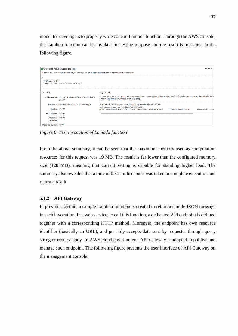
following figure.
Figure 8. Test invocation of Lambda function
From the above summary, it can be seen that the maximum memory used as computation
resources for this request was 19 MB. The result is far lower than the configured memory
size (128 MB), meaning that current setting is capable for standing higher load. The
summary also revealed that a time of 0.31 milliseconds was taken to complete execution and
return a result.
5.1.2 API Gateway
In previous section, a sample Lambda function is created to return a simple JSON message
in each invocation. In a web service, to call this function, a dedicated API endpoint is defined
together with a corresponding HTTP method. Moreover, the endpoint has own resource
identifier (basically an URL), and possibly accepts data sent by requester through query
string or request body. In AWS cloud environment, API Gateway is adopted to publish and
manage such endpoint. The following figure presents the user interface of API Gateway on
the management console.

38
Figure 9. Sample endpoint in API Gateway on AWS management console
The hello endpoint is created to listen for GET requests to call the sample Lambda function
“Hello World” by linking to its Amazon Resource Name (ARN). It is noted that each
resource on AWS cloud environment has a unique identifier (defined by AWS as ARN), and
hence of Lambda function. It is also possible to directly test the endpoint on AWS console
to check whether published API is working, and result is visually shown as below. Other
than that, AWS console shows trace log of any request with helpful information for
developers to debug.

39
Figure 10. Test API call on AWS console
The sample API is publicly accessible for all users to send requests and retrieve data.
However, in many cases, security requirements ask for access restriction so that only
permitted requesters are able to use the API. Thus, requesters must include into every call a
sort of credential authorized by the API publisher, in order to be identified. Fortunately, API
Gateway equips developers with built-in API keys for an instant implementation of
protection. Once being enabled, the API expects “x-api-key” header to consider valid
requests to accept, otherwise to reject them. Value of this header is set to the API key which
is generated and provisioned by API Gateway. The below figure demonstrates two requests
to this secured API, among them, the first request did not include “x-api-key” header but the

40
other did. The result reveals that the first attempt was forbidden with HTTP status code 403
returned to caller, whereas the second was successful. It got successful HTTP status code
200 and could retrieve returning data as a JSON string.
Figure 11. API requests demonstration
5.2 Source code control and other tools
In previous sub-chapter, a demonstration on AWS management console to create a sample
API resource of a web service is given. However, it is unpractical to track changes made by
navigating around the console, and hence of unmaintainable application, especially there are
many people involving in the project. Yet, it becomes more difficult to learn whoever
performs any code update or adjust few configurations of a AWS resource. As such, in order
to tackle the issue, it is crucial to adopt a versioning system to manage project’s code base
instead of direct update on the AWS management console. The version control software also

41
aims at tracking all relating AWS infrastructure employed to build the serverless application.
In other words, all changes should be recorded for revision, which can be traced easily and
probably reverted to previous settings in case of problems.
In this thesis, the author adopts Bitbucket [48] as the code management platform to control
source code of the serverless prototype application. The platform is developed by Atlassian
[49], equipping the author convenient solution to version the source code. A basic CI tool is
also integrated which will be used to build and deploy the project. Furthermore, Atlassian
offers reasonable subscription pricing for small team using their platform, and it is suitable
for this study’s budget.
5.3 Coding prototype application
5.3.1 Database
In this thesis, the developed prototype application is a RESTful web service with basic
CRUD operations (create, read, update, delete). It provides API for consumers to retrieve or
manipulate data records from a database by sending requests to appropriate HTTP endpoints.
Having noticed earlier, database design and its implementation are not included in the
project’s scope. By such, a sample database is adopted from the community of PostgreSQL
database engine [50]. A Linux virtual machine is also configured to serve as database server
for this purpose. Details about all database tables and their entities can be seen in the entity
relationship diagram placed in appendix of this thesis. It should be noted that not all entities
have been taken into development of the prototype application due to the research’s scope
and limitation.
5.3.2 Project structure
The below figure presents a look at the organization of the application where various
components as well as configuration files can be seen. At root directory, models directory
gathers all classes representing the database’s entities, for example actor, address, city and
country. Each model class defines properties for individual entity, serializes and maps it to
relevant table in the database. The functions directory contains all AWS Lambda functions,
being divided correspondingly to API resources of the prototype application. For instance,
sub-directory actor contains all functions to handle incoming requests from consumers and

42
executes relating business logics. Moreover, the author also includes several test data, saved
in JSON files, to simulate execution of those functions on local machine. Last but not least,
all shell scripts are centralized in the bashscripts directory. These scripts are used for testing,
validating code, building and deploying the application to AWS cloud environment.
Figure 12. Components and project structure
There are a number of configuration files in the project, namely “package.json”,
“serverless.yml”, “bitbucket-pipelines.yml”. Firstly, the JSON file contains list of required
software dependencies, and defines commands to run the shell script files in the bashscripts
directory. The file also stores description about the application, such as name, version
tagging, contributor and license. Meanwhile, “serverless.yml” is used to configure all

43
components and infrastructure of the serverless application to be deployed on AWS cloud
environment. To be specific, this YAML file organized settings for AWS Lambda functions,
including HTTP endpoints dedicated to them. In addition, computing memory, function
timeout, API key to protect application are also attached. In the meantime, “bitbucket-
pipelines.yml” applies configuration for the Bitbucket’s built-in CI tool to build and deploy
the application.
5.3.3 Dependencies management and installation
The project needs external software libraries, also known as dependencies, which are pre-
written code of functions, classes or scripts available for developers to reuse or integrate into
an application [51]. Those libraries help developers to reduce coding efforts and boost the
development process. Furthermore, many libraries (or dependencies) have been released and
supported by prestigious organizations or community of qualified developers, and hence of
less bugs or errors. In this project, the author adopts several software libraries, requiring to
be installed prior to any development work with AWS services. As being mentioned
previously, they are listed in the configuration file “package.json”. The below table provides
brief information about the most important dependencies used to support the prototype
application. In addition, the subsequent figure gives an instruction to install software
dependencies in Node.js application development project by shell command.
Table 6. Project dependencies summary
Name Purpose Item in package.json
Serverless
framework
Backbone library in this project that
provides support in building, deploying,
managing Lambda functions, API
Gateway and other AWS resources
"serverless": ">=1.11.0"
PostgreSQL
database
client
Providing connection gateway between
application and PostgreSQL database
"pg": "^6.1.5", "pg-hstore": "^2.3.2", "pg-pool": "^1.7.1"
Serialization
library
The Object-relational Mapping (ORM)
library allows application to interact
with data from a database via the
Object-oriented paradigm
"sequelize": "^3.30.4", "sequelize-cli": "^2.7.0"

44
Code
convention
check
Verifying new code against a universal
convention to maintain a standard way
of coding within development team
"eslint": "^3.19.0", "eslint-config-airbnb-base": "^11.1.3", "eslint-plugin-import": "^2.2.0"
Figure 13. Installation of software dependencies
5.3.4 API resources
The author utilizes configuration file “serverless.yml” in order to define all AWS Lambda
functions and APIs on API Gateway. All settings for these AWS resources are transformed
to code so that version control software could easily manage. At the top of “serverless.yml”,
the author defines necessary information for the application, such as stage (marking
application’s environment as staging or production for deployment), resources allocated to
Lambda functions (computing memory, timeout). Among them, application’s stage is
parameterized, therefore it can be flexibly deployed to different environments on AWS.

45
Runtime and memory of AWS Lambda are Node.js and 128 Megabytes, respectively.
Timeout is set to 6 seconds, meaning that AWS terminates execution of Lambda function
after this maximum duration in order to avoid infinite run. The mechanism also helps to
prevent meaningless cost, and hence of saving budget.
Figure 14. Configuration of first API
First endpoint of the prototype application is implemented for consumers to check health
status of the web service. It accepts requests made with HTTP method GET over the
network. Staying behind the endpoint, the AWS Lambda function is named as
probeGetHealth with brief description. The code file for this Lambda function is stated as
value of handler, which must be an absolute path within the project’s structure. The author
decides to allow public access to this API resource, meaning no credential or API key
required in HTTP requests. As such, value of the key private must be assigned to false.

46
On the other hand, the below API resources allows consumers to interact with database of
the prototype application, which requires a stricter access right. Those endpoints include
various HTTP methods, GET, POST and PUT, to retrieve, create and manipulate records of
actor table in the database. The below figure illustrates configurations of these endpoints in
the application’s “serverless.yml” configuration file. Due to the nature of database security,
it must be noted that these endpoints were private, which only accept traffics from identified
consumers. In other words, they must include a sort of assigned credential in every request
so as to bypass API’s firewall protection. Therefore, being differently than the health check,
the value of private is set to true for these endpoints.
Figure 15. Configuration of actor endpoints
From the above figure, the first GET endpoint, actorGetById searches for an individual actor
from the database by its ID (which is the identifier of the record on database). The actor’s
ID is attached to query string on the API’s Uniform Resource Identifier (URI) that can be
seen in sample request’s demo. Second, actorCreateNew is implemented to add new actor
to the database via POST requests. Detailed information about new actor must be sent in
request’s body. Meanwhile, in order to update details of a particular actor, consumers make
a PUT request to actorUpdate endpoint with data included in the body. Similar to retrieve
47
information of an actor, the URI of this API contains the ID of the actor. The below demo
gives examples of valid requests to these particular endpoints.
Figure 16. Sample requests with different HTTP methods
5.3.5 Business logic code
Amazon Web Services (AWS) Lambda function’s handlers store code of the application’s
business logic. Coding the handlers must follow a defined programming model documented
by AWS [52] to ensure compatibility with the AWS Lambda environment. Basically, the
handler is a function code to be invoked firstly whenever a function is executed. Handler’s
syntax contains three parameters, namely event, callback and context. Developers utilize the
event parameter to extract data being passed to Lambda functions, including request data
sent by API (Application Programming Interface) consumers. Depending on request method,
such data could be passed as query string or attached to request’s body. The Lambda function
follows defined business to process the data, then prepares result as response for API callers
by passing it through the callback parameter. Last but not least, the context parameter
represents an object which stores all runtime information of Lambda function, for example
different settings of the function, memory limit or execution time.
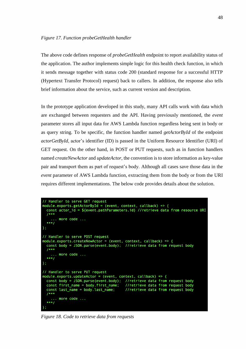
48
Figure 17. Function probeGetHealth handler
The above code defines response of probeGetHealth endpoint to report availability status of
the application. The author implements simple logic for this health check function, in which
it sends message together with status code 200 (standard response for a successful HTTP
(Hypertext Transfer Protocol) request) back to callers. In addition, the response also tells
brief information about the service, such as current version and description.
In the prototype application developed in this study, many API calls work with data which
are exchanged between requesters and the API. Having previously mentioned, the event
parameter stores all input data for AWS Lambda function regardless being sent in body or
as query string. To be specific, the function handler named getActorById of the endpoint
actorGetById, actor’s identifier (ID) is passed in the Uniform Resource Identifier (URI) of
GET request. On the other hand, in POST or PUT requests, such as in function handlers
named createNewActor and updateActor, the convention is to store information as key-value
pair and transport them as part of request’s body. Although all cases save those data in the
event parameter of AWS Lambda function, extracting them from the body or from the URI
requires different implementations. The below code provides details about the solution.
Figure 18. Code to retrieve data from requests

49
5.4 Application build and deployment
A continuous integration (CI) software is adopted to build and deploy the prototype
application. Whenever changes occurring in the project’s code base, the CI software runs
pre-configured job to release new application version to the Amazon Web Services (AWS)
environment. The process will be triggered automatically or manually. In this project, the
author employs Bitbucket platform [48] as version control system to host the code. Atlassian
[49] also integrates a simple CI software into Bitbucket to assist build automation. This built-
in CI tool is adequate and fulfills requirements of the prototype development. Apparently,
different projects may demand more advanced CI software with the ability to tweak, such as
Jenkins [53] or Atlassian Bamboo [54], to fit their works and project’s scopes.

50
Figure 19. Insight into build and deployment pipeline
The author defines different tasks for CI job in the configuration “bitbucket-pipelines.yml”
and shell scripts. The configuration file follows convention documented by Atlassian to
obtain compatibility with the Bitbucket CI software. In other words, the CI tool firstly read
settings from this file to know about tasks to execute. Furthermore, the configuration lists all
deployment jobs for both staging and production environment, which are triggered by
changes in develop and master branches, respectively. Meanwhile, the shell script
51
“pipeline.sh”, placed in directory bashscripts, consists of various tasks to perform in the
deployment pipeline according to application’s environment. In general, following tasks are
defined:
• Installing required software dependencies for the project
• Validating convention of the code
• Updating structure of database table (if necessary)
• Executing scripts to update new code for Lambda functions and other AWS resources
• Checking application health by calling the health check endpoint
At lower view of the deployment pipeline, the CI tool performs updates for AWS resources
which serve as components of the prototype application. Infrastructure changes are detected
from the “serverless.yml” file to inform AWS CloudFormation to update corresponding
resources. In other words, AWS CloudFormation is a service to easily create and maintain
collections of related resources that assemble a software and contribute to its development
[18]. Basically, in the AWS environment, all settings for the application’s components and
its necessary resources are centralized and wrapped into a CloudFormation stack. Running
any update on this stack results into migrating changes in all resources under its
management.
To be specific, CloudFormation manages provision of the backbone services of the
serverless prototype application. Taken inputs from the “serverless.yml” configuration,
CloudFormation set all definitions and configurations for Lambda functions and API
Gateway. Application code is kept in a S3 bucket prior to apply to Lambda functions for
latest changes. Last but not least, other relevant and necessary AWS services are also updated
by CloudFormation in order to ensure application’s availability, for instance IAM roles and
policies to manage access and operation permission to all resources within the AWS
environment [18].

52
Figure 20. Failure versus success in deployment pipeline
The above figure illustrates two contrary scenarios of the deployment pipeline revealed in
the CI tool’s console. Once all deployment tasks being successfully executed, deployment
pipeline is marked as success, meaning a healthy service was ready to serve. In contrast,
whenever being considered failure due to any unsuccessful task, the pipeline rejects new
code deployment and reverts to latest stable version. This rollback mechanism is useful to
avoid unhealthy application state, and possibly service break. In other words, rollback also
helps to ensure no malfunction or misleading behaviors of the application.
5.5 Monitoring and maintenance
The operational monitoring of serverless application is done through CloudWatch, a
monitoring service to automatically collects operation information of resources and running
application on the cloud [18]. Yet, CloudWatch streams activities and events concerning the
prototype application to different log streams containing their time and details. To be
specific, API (Application Programming Interface) Gateway traces all consumer’s calls to
each endpoint and records them into different metrics, such as number of requests, duration

53
as well as error counts. To be added, CloudWatch also distinguishes them by environments
(staging or production). Taken as an example, the below figure presented a graph of metrics
concerning API calls in staging environment of this prototype application.
Figure 21. Graphed metrics of API requests
Meanwhile, CloudWatch collects logs of Amazon Web Services (AWS) Lambda functions
and categorizes them into separate groups corresponding to each individual function. Inside
a log group, log messages are split into various streams with a reasonable number of items
to facilitate lookup. AWS also equips CloudWatch with filter box to assist developers to
search for wanted log items based on names. Therefore, in the development of this prototype
application, the author adopts a naming convention for Lambda functions. The purpose is to
distinguish those functions from serving environment, and hence of easily locating correct
application logs.

54
Figure 22. Logs of Lambda functions on CloudWatch
Taking a deeper look, a log stream contains many events, in which a single event represents
an invocation time of AWS Lambda function. As can be seen from above example, each
event has information about execution time and computing memory consumed. In addition
to default log messages, developers can implement custom logging mechanism to store more
useful operation information of the application. Yet, custom logs possibly include some sorts
of explanation about requesters who call the API and details of the call. Such information is
meaningful to application debug whenever errors or incidents occur. Depending on nature
of chosen programming language, logging messages are outputted in diverse ways, but they
will be automatically saved in a log stream on CloudWatch.

55
5.6 Summary
In this Chapter 5, implementation of a serverless prototype application is comprehensively
discussed with the aim of proving the concept of serverless architecture. First, the author
equips readers with a brief introduction about backbone services of the serverless
architecture used from Amazon Web Services (AWS). The introduction also give instruction
about creating and using those services directly from the AWS management console.
However, solely using this approach to maintain resources is unpractical because it is hard
to track application’s changes and do automation deployment. Thus, it should include
necessary software and tools to support the development process, which are given
subsequently in below table. Third, detailed discussion about the technical implementation,
project structure, and coding techniques are mentioned. It also explains about software
dependencies and library needed for the prototype application. Their usage purposes,
functionalities as well as installation are reviewed. Subsequently, the fourth issue is the use
of continuous integration (CI) platform to automatically build and deploy the application to
AWS. Last but not least, briefing about operation monitoring and application maintenance
is also covered.
Evaluation of the design artefact introduced in this thesis is conducted by confirming the
reliability and usability of the serverless architecture in developing web service application.
There are several techniques and methods to use in design evaluation [23], among which the
experimental method is employed. The design artefact is studied in laboratory environment,
in which elements affecting to the artefact’s operation and behaviors are controlled based on
pre-defined conditions [55]. Yet, the author simulates a software project to apply the
serverless architecture and its development practice. The software requirements are not
created from actual analysis of any business need. Furthermore, a small team of three virtual
developers are also formed. They participate in the project and simultaneously commit
changes to the code base. All in all, the simulated project aims at creating a web service,
deploy it to AWS cloud environment, maintain and monitor its operation. Meanwhile, the
team follows the suggested development practice, containing different conventions for
source code management, code review, as well as project build and deployment. The author
reveals the result that the design artefact is successfully adopted into creating a workable
web application. The prototype dedicates to run on AWS and utilizes its services to serve as
components of the architecture.

56
The prototype application provides consumers different APIs (Application Programming
Interfaces) to interact with the backend and execute corresponding business logics. It can be
achieved by sending requests to suitable API endpoint with appropriate data through
Hypertext Transfer Protocol (HTTP) calls. API’s consumers set methods in each request to
perform appropriate CRUD (Create – Read – Update - Delete) operations. The application
decides which operation to use and what to execute according to the HTTP verb and data it
receives. In a RESTful web service, HTTP method GET is used to retrieve data, whereas
POST, PUT and DELETE methods to manipulate records in database, which are to add new
record, adjust and remove existing one, respectively [33]. As a conclusion, the following
table gives a summary of cloud services to serve as components of the serverless
architecture. Moreover, employed tools and software to support the development of
prototype application are also listed.
Table 7. Summary of prototype application
Software or services Note
Amazon Web Services
API Gateway API container
AWS Lambda Serverless computing platform
CloudWatch Logging system
CloudFormation Deploying AWS resources
S3 bucket Lambda function code storage
Source code management Git Version control software
Atlassian Bitbucket Code repository
Continuous integration
software Bitbucket Pipeline Being integrated into Bitbucket

57
6 TESTING SERVERLESS PROTOTYPE APPLICATION
Performance of the prototype application is studied to understand feasibility to adopt the
serverless architecture into building production web services. The author employs load
testing [40] to watch application’s operation in different scenarios and configurations. Main
purpose is to examine application’s behaviors under various load conditions. To fulfill the
goal, the author utilizes a cloud-based testing software to execute tests. Within this section,
the tests’ setup and results are summarized together with comprehensive discussions about
such results.
6.1 Mutual testing configuration
In this study, mutual settings used in test scenarios are virtual user, loading iterations, and
test duration, being listed in below table. Other configurations of ramp-up and delay times
are distinguishing to generate distinct levels of stress on the application in each scenario.
These elements will be discussed explicitly in each scenario. It should be noted about the
restrictions on allocating resources for the load testing. Due to tight budget of this research,
the author must choose a very basic load test option, which prevents to have higher loads to
the application. The budget subscription allows to bring up maximum of 50 concurrent users
in a test.
Table 8. Configuration elements [56]
Setting Explanation Applied number
Virtual users Number of concurrent users to simulate heavy usage
of many people. 50
Iterations
Number of time a test will be run until completed.
Infinite iterations setting is equivalent to unlimited
execution.
infinite
Duration Maximum load time of a test before it is terminated. 6 minutes
Delay time
(milliseconds) Delay time between HTTP requests. Depending on test
Ramp-up
(seconds) The time required to bring all virtual users online. Depending on test
A total of five test scenarios are executed, being categorized into two groups. The group A
consists of requests to four API endpoints of the prototype, in which third quarter of them
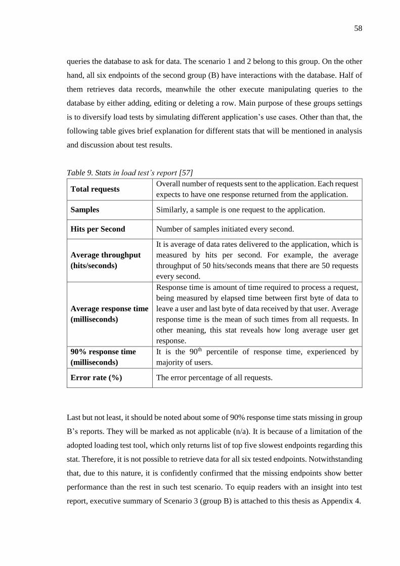
58
queries the database to ask for data. The scenario 1 and 2 belong to this group. On the other
hand, all six endpoints of the second group (B) have interactions with the database. Half of
them retrieves data records, meanwhile the other execute manipulating queries to the
database by either adding, editing or deleting a row. Main purpose of these groups settings
is to diversify load tests by simulating different application’s use cases. Other than that, the
following table gives brief explanation for different stats that will be mentioned in analysis
and discussion about test results.
Table 9. Stats in load test’s report [57]
Total requests Overall number of requests sent to the application. Each request
expects to have one response returned from the application.
Samples Similarly, a sample is one request to the application.
Hits per Second Number of samples initiated every second.
Average throughput
(hits/seconds)
It is average of data rates delivered to the application, which is
measured by hits per second. For example, the average
throughput of 50 hits/seconds means that there are 50 requests
every second.
Average response time
(milliseconds)
Response time is amount of time required to process a request,
being measured by elapsed time between first byte of data to
leave a user and last byte of data received by that user. Average
response time is the mean of such times from all requests. In
other meaning, this stat reveals how long average user get
response.
90% response time
(milliseconds)
It is the 90th percentile of response time, experienced by
majority of users.
Error rate (%) The error percentage of all requests.
Last but not least, it should be noted about some of 90% response time stats missing in group
B’s reports. They will be marked as not applicable (n/a). It is because of a limitation of the
adopted loading test tool, which only returns list of top five slowest endpoints regarding this
stat. Therefore, it is not possible to retrieve data for all six tested endpoints. Notwithstanding
that, due to this nature, it is confidently confirmed that the missing endpoints show better
performance than the rest in such test scenario. To equip readers with an insight into test
report, executive summary of Scenario 3 (group B) is attached to this thesis as Appendix 4.

59
6.2 Group A - Scenario 1
In the first configuration, the application is tested by continuously receiving number of
requests to different GET endpoints. Ramp-up and delay periods are set to 120 seconds and
500 milliseconds, respectively. This setup results in 27486 requests over a period of 6
minutes. In other words, the application prototype is stressed at average throughput of 76.6
hits per second.
Table 10. Scenario 1 - Test configuration and summary
Test configuration Ramp-up 120 seconds
Delay time 500 milliseconds
Executive results
(all endpoints)
Total requests 27486 samples
Average throughput 76.6 hits/second
Average response time 53 milliseconds
90% response time 66 milliseconds
Error rate 0%
Apparently, it is witnessed that the prototype application easily handles all requests without
any error. Specifically, average response times of all endpoints are 53 milliseconds (ms),
and being stable at 66 milliseconds (with a rate of 90% all requests). The following table
presents more details about explicit outcomes of each endpoint.
Table 11. Scenario 1 - All endpoint’s results
Name Endpoints Samples Hits/s Average time
(ms)
90% time
(ms)
Health check
(service information) GET /probe/health 6888 19.19 66.92 70
Get an actor
(retrieve an actor
from its id)
GET /actor/13 6855 19.53 50.32 59

60
Get all countries
(list all countries) GET /country 6866 19.45 49.68 64
Get a country
(retrieve a country
from its id)
GET /country/100 6877 19.32 43.58 55
In addition, the below figure illustrates application’s behavior during load period. As can be
clearly seen, average response time mostly stabilizes, even when number of users increases
(leading to higher total hits per second). It is also noted that there are spikes in response time
at beginning and ending of the test, which lower overall performance.
Figure 23. Scenario 1 - Timeline report
6.3 Group A - Scenario 2
Second stress targets at same endpoints with the first scenario, but few different settings are
applied in order to generate higher load. The author set ramp-up to 50 seconds while delay
was reduced to 100 milliseconds. Consequently, in comparison with the first scenario, this
setup bombards the application with quadruple number of requests within the identical
testing time of 6 minutes. To be specific, the author witnesses an aggregate 112174 hits,
meaning that in every second the application must handle an average of 311.6 requests.
Table 12. Scenario 2 - Test configuration and summary

61
Test configuration Ramp-up 50 seconds
Delay time 100 milliseconds
Executive results
(all endpoints)
Total requests 112174 samples
Average throughput 311.6 hits/second
Average response time 49 milliseconds
90% response time 68 milliseconds
Error rate 0.01% (7 samples)
Despite few errors, it is confident to confirm capability of the prototype application for
managing this level of stressing. Yet, the author considers error rate of 0.01% to be
insignificant in this case, in which there are only 7 error samples in such huge sample size.
In the meantime, interestingly, average response of this test scenario is slightly faster than
the first one (49 versus 53 milliseconds) although much higher demand for throughput
occurred. Taking further look at each endpoint, most of them have better performances than
in the first test scenario. Especially, “Get an actor” endpoint shows nearly 22% faster,
meaning a big gap from the author’s perspective.
Table 13. Scenario 2 - All endpoint’s results
Name Endpoints Samples Hits/s Average time
(ms)
90% time
(ms)
Health check
(service information) GET /probe/health 28063 77.95 67.35 78
Get an actor
(retrieve an actor
from its id)
GET /actor/13 28024 78.28 39.26 54
Get all countries
(list all countries) GET /country 28037 78.10 46.03 62
Get a country
(retrieve a country
from its id)
GET /country/100 28050 78.13 41.36 56
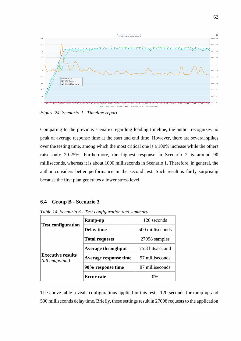
62
Figure 24. Scenario 2 - Timeline report
Comparing to the previous scenario regarding loading timeline, the author recognizes no
peak of average response time at the start and end time. However, there are several spikes
over the testing time, among which the most critical one is a 100% increase while the others
raise only 20-25%. Furthermore, the highest response in Scenario 2 is around 90
milliseconds, whereas it is about 1000 milliseconds in Scenario 1. Therefore, in general, the
author considers better performance in the second test. Such result is fairly surprising
because the first plan generates a lower stress level.
6.4 Group B - Scenario 3
Table 14. Scenario 3 - Test configuration and summary
Test configuration Ramp-up 120 seconds
Delay time 500 milliseconds
Executive results
(all endpoints)
Total requests 27098 samples
Average throughput 75.3 hits/second
Average response time 57 milliseconds
90% response time 87 milliseconds
Error rate 0%
The above table reveals configurations applied in this test - 120 seconds for ramp-up and
500 milliseconds delay time. Briefly, these settings result in 27098 requests to the application

63
(relatively similar to the first scenario), being tantamount to 75.3 per every second. In
addition, the result also reveals that the application successfully passes this third load test
without any error. Average performance is comparatively similar to the first and second tests,
which all stay below 60 milliseconds to return a response. In contrast, Scenario 3 indicates
a less positive number regarding the rate of 90% response time. This stat stabilizes at
averagely 87 milliseconds to each request for the majority of users. More specifically, the
application shows lower performance in comparison with the previous test scenarios, which
are 66 and 68 milliseconds, respectively.
In the explicit analysis of each endpoint, all of them have very much alike stats, ranging
from 40 to under 50 milliseconds of average response time. Meanwhile, the average response
times of “Create new actor” and “Get a country” double, being at 86.36 and 81.87
milliseconds. The reason for slower response time probably causes from complicated
settings of this test plan, which contains both reading and writing operations to database.
Notwithstanding that, the author would like to consider an acceptable performance in this
Scenario 3, especially when the application flawlessly handles all requests.
Table 15. Scenario 3 - All endpoint’s results
Name Endpoints Samples Hits/s Average time
(ms)
90% time
(ms)
Create new actor
(add new actor to
database)
POST /actor 4538 12.61 86.36 102
Get all countries
(list all countries) GET /country 4532 12.62 49.64 64
Edit an actor
(update information
of an actor)
PUT /actor/4999 4518 12.62 40.06 n/a
Get an actor
(retrieve an actor
from its id)
GET /actor/3999 4513 12.64 44.26 57
Delete an actor
(remove actor from
database by its id)
DELETE /actor/699 4497 12.63 41.39 56

64
Get a country
(retrieve a country
from its id)
GET /country/50 4500 12.64 81.87 98
* n/a: not applicable
Figure 25. Scenario 3 - Timeline report
As can be seen, the average response time is quite stable over most of loading time.
Furthermore, the graph illustrates a downward trend from above to below point of 60
milliseconds. There is a huge spike at the end in the timeline when the response time almost
triples. It also shows spikes at the beginning, being much similar to the previous test plans.
However, it is positive to witness a significantly lower peak time, staying at slightly above
160 milliseconds in comparison with around 1000 milliseconds in the Scenario 1.
6.5 Group B - Scenario 4
Having suffered from slower response in Scenario 3, this test configuration is not set to
possible maximum numbers yet so as to gently increase stress level. Ramp-up duration
reduces to 50 seconds, meanwhile 200-millisecond delay time is adopted - a decrease of
60%. As a consequence, a total number of 58628 requests is generated, being equivalent to
163.3 hits per second logged. On the other side, for all endpoints, it takes averagely 86
milliseconds (or 104 milliseconds in 90th percentile) to return a response to user. Comparing
to other test scenarios, the executive report reveals a lower performance in general. However,
this test’s result is still good because error rate stays at 0% and around 100 milliseconds in
response time is still positive number from the author’s viewpoint.

65
Table 16. Scenario 4 - Test configuration and summary
Test configuration Ramp-up 50 seconds
Delay time 200 milliseconds
Executive results
(all endpoints)
Total requests 58628 samples
Average throughput 163.3 hits/second
Average response time 86 milliseconds
90% response time 104 milliseconds
Error rate 0%
Table 17. Scenario 4 - All endpoint’s results
Name Endpoints Samples Hits/s Average time
(ms)
90% time
(ms)
Create new actor
(add new actor to
database)
POST /actor 9801 27.30 258.89 160
Get all countries
(list all countries) GET /country 9795 27.36 59.13 88
Edit an actor
(update information
of an actor)
PUT /actor/4999 9777 27.31 60.08 85
Get an actor
(retrieve an actor
from its id)
GET /actor/3999 9753 27.32 49.29 70
Delete an actor
(remove actor from
database by its id)
DELETE /actor/699 9751 27.31 44.13 62
Get a country
(retrieve a country
from its id)
GET /country/50 9751 27.39 43.05 n/a
* n/a: not applicable
To understand the reason, the author examines each API endpoint separately and explores a
three times lower performance of “Create new actor”. Average response time for POST
requests to this endpoint is 258.89 milliseconds, but the 90% of users experience faster time

66
at 160 milliseconds. In other words, it seems that a minor number of requests gets
exceptional behavior of 1.5 times slower feedbacks. Regardless this endpoint, all of the
others show much similar performance like in other scenarios, in terms of both average and
90% response time.
Figure 26. Scenario 4 - Timeline report
The timeline chart reveals relatively unstable response time during the load test, being
dissimilar experience from the other tests. The graph shows huge spikes, in which response
time skyrockets from under 100 milliseconds per request to 400, 500 or even 600
milliseconds. In addition, hits per second fluctuates greatly, meanwhile in other test
scenarios such number stabilizes at a constant rate. The author recognizes that throughput
hits drops correspondingly to whenever spikes occurred. As such, load level temporarily
declines, making the application handle all requests more easily at that moment. In a word,
considerable spikes and decreases in interim throughput contribute to the relative lower
performance, indicating a weaker ability of the prototype application to handler massive
requests.
6.6 Group B - Scenario 5
Despite slower response in Scenario 4, the application does not fail any request. Therefore,
it is worth trying a higher stress level in this fifth test plan. As such, the ramp-up and delay

67
time are set to their possible maximum of the load test subscription. Such settings are
identical to them in the Scenario 2 of group A. Consequently, the application has to handle
a total number of 111706 requests, in corresponding to approximately 18600 samples for
each endpoint. The total average throughput is 311.2 hits per second, being divided to around
51.92 hits reaching an individual resource each second.
Table 18. Scenario 5 - Test configuration and summary
Test configuration Ramp-up 50 seconds
Delay time 100 milliseconds
Executive results
(all endpoints)
Total requests 111706 samples
Average throughput 311.2 hits/second
Average response time 49 milliseconds
90% response time 84 milliseconds
Error rate 0%
Result reveals that the application successfully manages the load with error-free.
Surprisingly, it can be seen that response time of all endpoints is better than previous tests
in group B. Most endpoints also have more positive performance at around 39 to 46
milliseconds in response time, excepting “Create new actor”. This individual POST
endpoint is slower than the others, requiring averagely 90 milliseconds to reply a request.
Notwithstanding that, despite much higher load, it should be admitted that the application
showed a favorable performance. Yet, in this case, the stress level of Scenario 5 doubles and
quadruples in comparison with Scenario 4 and Scenario 3, respectively.
Table 19. Scenario 4 - All endpoint’s results
Name Endpoints Samples Hits/s Average time
(ms)
90% time
(ms)
Create new actor
(add new actor to
database)
POST /actor 18638 51.92 90.43 110
Get all countries
(list all countries) GET /country 18626 52.03 46.65 63
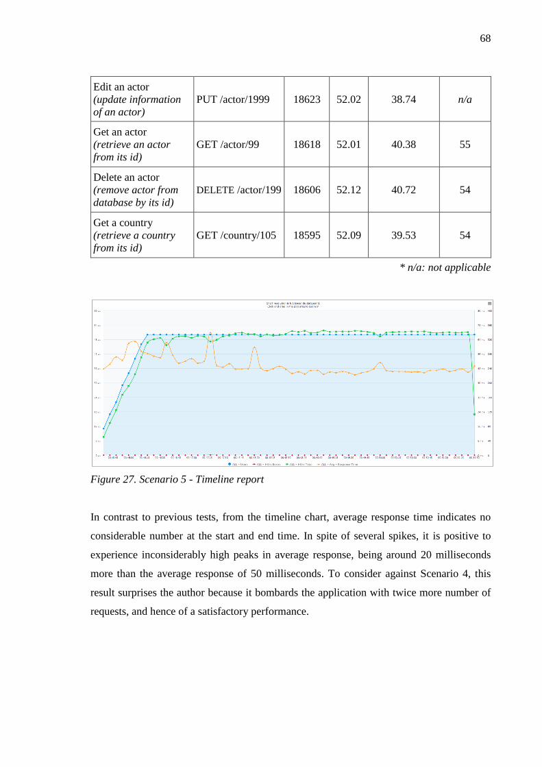
68
Edit an actor
(update information
of an actor)
PUT /actor/1999 18623 52.02 38.74 n/a
Get an actor
(retrieve an actor
from its id)
GET /actor/99 18618 52.01 40.38 55
Delete an actor
(remove actor from
database by its id)
DELETE /actor/199 18606 52.12 40.72 54
Get a country
(retrieve a country
from its id)
GET /country/105 18595 52.09 39.53 54
* n/a: not applicable
Figure 27. Scenario 5 - Timeline report
In contrast to previous tests, from the timeline chart, average response time indicates no
considerable number at the start and end time. In spite of several spikes, it is positive to
experience inconsiderably high peaks in average response, being around 20 milliseconds
more than the average response of 50 milliseconds. To consider against Scenario 4, this
result surprises the author because it bombards the application with twice more number of
requests, and hence of a satisfactory performance.
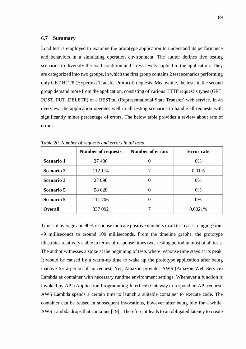
69
6.7 Summary
Load test is employed to examine the prototype application to understand its performance
and behaviors in a simulating operation environment. The author defines five testing
scenarios to diversify the load condition and stress levels applied to the application. They
are categorized into two groups, in which the first group contains 2 test scenarios performing
only GET HTTP (Hypertext Transfer Protocol) requests. Meanwhile, the tests in the second
group demand more from the application, consisting of various HTTP request’s types (GET,
POST, PUT, DELETE) of a RESTful (Representational State Transfer) web service. In an
overview, the application operates well in all testing scenarios to handle all requests with
significantly minor percentage of errors. The below table provides a review about rate of
errors.
Table 20. Number of requests and errors in all tests
Number of requests Number of errors Error rate
Scenario 1 27 486 0 0%
Scenario 2 112 174 7 0.01%
Scenario 3 27 098 0 0%
Scenario 5 58 628 0 0%
Scenario 5 111 706 0 0%
Overall 337 092 7 0.0021%
Times of average and 90% response indicate positive numbers in all test cases, ranging from
49 milliseconds to around 100 milliseconds. From the timeline graphs, the prototype
illustrates relatively stable in terms of response times over testing period in most of all tests.
The author witnesses a spike at the beginning of tests where response time stays at its peak.
It would be caused by a warm-up time to wake up the prototype application after being
inactive for a period of no request. Yet, Amazon provides AWS (Amazon Web Service)
Lambda as container with necessary runtime environment settings. Whenever a function is
invoked by API (Application Programming Interface) Gateway to respond an API request,
AWS Lambda spends a certain time to launch a suitable container to execute code. The
container can be reused in subsequent invocations, however after being idle for a while,
AWS Lambda drops that container [19]. Therefore, it leads to an obligated latency to create

70
a new container. Differently than others, Scenario 4 reveals fluctuating response times over
the 6-minute stressing period with several huge spikes. This exceptional performance is
surprising as loading level is still twice lower than Scenario 5, in which the stat stabilizes.
Taking closer look at tested API’s endpoints, they have showed likely similar figures in the
both stats, meaning that the application has same performance in different load conditions.
Among them, it is seen that HTTP requests manipulating data records in database (POST,
PUT and DELETE) require longer time to be completed.
71
7 CONCLUSION
7.1 Findings and discussion
In this thesis, design science approach is employed to conduct the research. The output of
the research process is a design artefact, which consists of the serverless architecture and its
development practice. The serverless architecture is an approach to build web services, while
the development practice equips development team with a way to adopt it. As such, the
author answers two main research questions (RQ) introduced in the chapter 2.
RQ1: What are main components of serverless architecture?
Main components of the serverless architecture are a serverless computing platform, API
(Application Programming Interface) container and an operation monitoring tool. They are
different cloud services provided by a cloud vendor. Among them, the computing platform
is an ephemeral container with necessary software dependency installed to execute
application’s code without any server provisioning activities. API container helps publish,
control access and maintain different APIs for consumer’s usages to call backend service.
Meanwhile, the monitoring tool tracks and stores operating logs of the application, which
are useful to debug in case of incidents. Furthermore, database and supplement services
(such as e-mail, phone or data storage) can be integrated into a serverless application in order
to fulfill certain business requirements.
RQ2: What is the development practice of serverless architecture?
Various tools and software are employed in development of a serverless web application or
web services. First, a version control software is used to maintain a common repository to
provision changes of code base. The source code not only includes business logic but also
all infrastructure configurations to serve the serverless application. Second, a continuous
integration (CI) tool equips development team with the ability to build and deploy
application to cloud environment. In addition, CI tool manages this process in an automated
manner to increase working efficiency as well as time-saving. By using version control
software, two development branches (develop and master) are dedicated for staging and
production versions of the application, which are corresponding to the testing (staging) and
production environments of the application. Developers create an isolated branch to write
code for new feature. After being reviewed by others, this feature branch can be merged into

72
develop branch for deploying to test environment. Once new feature is verified and passes
all tests, it is merged into master branch for production release. Changes pushed to develop
or master branch will trigger build and deployment process, which are defined by relevant
jobs in the CI platform.
The design artefact introduced in this thesis contains the serverless architecture and
development practice to adopt the serverless architecture into building web services. It aims
at solving business problem of a need for approach to develop and maintain web services
without any worries about server provision. The presented artefact is delivered in the form
of a model, containing the serverless architecture (illustrated in figure 4 in chapter 4.1) and
a practice to adopt into development (illustrated in figure 6 in chapter 4.3. Specifically, the
approach asks for less mandatory maintenance works relating to the application, such as
procurement, installation and upgrade for both hardware and software. It helps reduce time
and efforts of development team as the concerns are shifted to other party. Yet, cloud vendors
are responsible for infrastructure, computing platform as well as necessary services at its
highest availability and uptime. In other words, developers can focus on writing code, testing
and deploying application at high scalability.
Following the guidelines of design science process, the author evaluates the outcome design
artefact in terms of its utility, quality and efficacy. Thus, in controlled laboratory settings, a
prototype application is developed with the adoption of the serverless architecture and
introduced development practice. The prototype is powered by Amazon Web Service (AWS)
cloud environment, being a proof-of-concept to confirm the feasibility and usability of the
design artefact. A small team of three virtual developers is simulated to join the project,
continuously write code for application’s functionality, and push to the code base for build
and deployment. Load testing is employed to check and evaluate the performance of the
prototype application. Different scenarios and test cases are configured to watch the
application’s behaviors in various stressing level. The loading test reveals promising results
as the application is capable for handling all tests with a very minor error in comparison with
a considerable number of requests. As such, from the study, the author can confirm the
feasibility of the design artefact of the serverless architecture and the development practice.

73
7.2 Research limitation and further research suggestion
There are limitations in this research to be discussed within this section. First, the research
is not executed with full steps of design science process as it skips justification and
communication of findings with the community (both technology and management oriented
people). This limitation can be resolved by empirical studies of commercial projects in which
the serverless architecture and practice are adopted. Researchers observe the development
process, and collect evidence to conduct analysis of the adopted approach. Through the
study, utility, quality and efficacy of the design artefact can be evaluated with real-world
validation. Second, the development of serverless prototype application is limited to the
Amazon Web Services (AWS) environment. AWS Lambda, API (Application Programming
Interface) Gateway, AWS CloudWatch and others are concerning services in the design as
well as implementation. As a result, it probably leads to the falsifiability of this study’s
findings when implementing with other cloud vendors available in the market. Third,
technical implementation of the prototype application is counted as one limitation. Database
design is excluded from the scope of this research. The design is an open-source sample from
the PostgreSQL community. The database server is not powered by any cloud services but
running on regular virtual machine. Moreover, the author picks JavaScript and Nodejs as the
sole programming language and technology of choice. As such, it would falsify the
research’s results when developing with other technologies, or design and implementation
of database are included.
Based on the limitations pointed above, the author would like to give suggestions on further
research regarding the serverless architecture. First, adoption of the design artefact into
commercial project can be examined. It helps to validate and justify the serverless
architecture in real-world environment rather than in controlled laboratory configuration in
this thesis. Second, the implementation of serverless architecture on cloud environment
provided by other vendors can be studied. Those cloud providers can be Google Cloud and
Microsoft Azure. Such studies will diversify the findings of this thesis in which the author
only concentrate on Amazon Web Services.
74
REFERENCES
[1] M. P. Papazoglou, Web Services: Principles and Technology, Tilburg: Pearson
Education, 2008.
[2] D. Krafzig, K. Banke and D. Slama, Enterprise SOA: Service-Oriented Architecture
Best Practices, New Jersey: Prentice Hall PTR, 2004.
[3] L.-J. Zhang, "EIC Editorial: Introduction to the Body of Knowledge Areas of Services
Computing," IEEE Transactions on Services Computing, vol. 1, no. 2, pp. 62-74, 2008.
[4] A. Barros and M. Dumas, "The Rise of Web Service Ecosystems," IT Professional,
vol. 8, no. 5, pp. 31-37, 2006.
[5] M. Endrei, J. Ang, A. Arsanjani, S. Chua, P. Comte, P. Krogdahl, M. Luo and T.
Newling, Patterns: Service-oriented Architecture and Web Services, 1st Edition ed.,
New York: IBM, 2004.
[6] S. Helal, J. Hammer, J. Zhang and A. Khushraj, "A Three-Tier Architecture for
Ubiquitous Data Access," in Proceedings ACS/IEEE International Conference on
Computer Systems and Applications, Beirut, 2001.
[7] A. O. Ramirez, "Three-Tier Architecture," Linux Journal, vol. 2000, no. 75es, July
2000.
[8] H. Kreger, "Web Services Conceptual Architecture (WSCA 1.0)," IBM Software
Group, Somers, 2001.
[9] L. Richardson and M. Amundsen, RESTful Web APIs: Services for a Changing World,
Sebastopol: O'Reilly Media, 2013.
[10] Z. Shao, H. Jin and D. Zhang, "A Performance Study of Web Server Based on
Hardware-Assisted Virtual Machine," in Computer Systems and Applications, 2009.
AICCSA 2009. IEEE/ACS International Conference, Rabat, 2009.
[11] F. Abidi and V. Singh, "Cloud Servers vs. Dedicated Servers - A Survey," in
Innovation and Technology in Education (MITE), 2013 IEEE International
Conference in MOOC, Jaipur, 2013.
[12] Ž. Stojanov and D. Dobrilović, "An Approach to Integration of Maintenance Services
in Educational Web Portal," in IEEE 8th International Symposium on Intelligent
Systems and Informatics, Subotica, 2010.

75
[13] D. Cvetkovic, M. Mijatovic and B. Medic, "Web Service Model for Distance Learning
Using Cloud Computing Technologies," in 2017 40th International Convention on
Information and Communication Technology, Electronics and Microelectronics
(MIPRO), Opatija, 2017.
[14] A. Handy, "Amazon Introduces Lambda, Containers at AWS re:Invent," BZ Media
LLC, 14 November 2014. [Online]. Available: http://sdtimes.com/amazon-introduces-
lambda-containers/. [Accessed 18 October 2016].
[15] Google Inc., "Cloud Functions," Google Inc., 11 February 2016. [Online]. Available:
https://cloud.google.com/functions/. [Accessed 18 October 2016].
[16] IBM, "Announcing IBM Bluemix OpenWhisk," IBM, 22 February 2016. [Online].
Available: https://developer.ibm.com/openwhisk/2016/02/22/announcing-ibm-
bluemix-openwhisk/. [Accessed 18 October 2016].
[17] M. Roberts, "Serverless Architecture," ThoughtWorks, 4 August 2016. [Online].
Available: https://martinfowler.com/articles/serverless.html. [Accessed 28 November
2017].
[18] Amazon Web Services, Inc., "Overview of Amazon Web Services," Amazon Web
Services, Inc., Seattle, 2017.
[19] Amazon Web Services, Inc., "AWS Lambda: How It Works," 19 11 2017. [Online].
Available: http://docs.aws.amazon.com/lambda/latest/dg/lambda-introduction.html.
[Accessed 19 11 2017].
[20] Serverless Inc., "Serverless Framework," Serverless Inc., 12 October 2015. [Online].
Available: https://serverless.com/framework/. [Accessed 18 October 2016].
[21] ServerlessConf, "ServerlessConf," 18 October 2016. [Online]. Available:
http://serverlessconf.io/. [Accessed 18 October 2016].
[22] Lappeenranta Academic Library, "LUT Finna," 25 06 2017. [Online]. Available:
https://wilma.finna.fi/lut/. [Accessed 25 06 2017].
[23] A. R. Hevner, S. T. March, J. Park and S. Ram, "Design Science in Information
Systems Research," Management Information Systems Quarterly, vol. 28, no. 1, pp.
75-105, March 2004.
[24] S. T. March and G. F. Smith, "Design and Natural Science Research on Information
Technology," Decision Support Systems, vol. 15, no. 4, pp. 251-266, December 1995.

76
[25] Amazon Web Services, Inc., "Amazon Web Services: Overview of Security
Processes," Amazon Web Services, Inc., Seattle, 2016.
[26] D. Fensel, H. Lausen, A. Polleres, J. d. Bruijn, M. Stollberg, D. Roman and J.
Domingue, Enabling Semantic Web Services: The Web Service Modeling Ontology,
Berlin: Springer, 2007.
[27] P. A. Bernstein, "Middleware: An Architecture for Distributed System Services,"
Digital Equipment Corportation, Cambridge, 1993.
[28] A. D. Birell and B. J. Nelson, "Implementing Remote Procedure Calls," ACM
Transactions on Computer Systems, vol. 1, no. 2, pp. 39-59, 1984.
[29] G. Coulouris, J. Dollimore, T. Kindberg and G. Blair, Distributed Systems: Concepts
and Design, 5th Edition ed., Essex: Pearson Education Limited, 2011.
[30] A. Watson, "OMG (Object Management Group) Architecture and CORBA (Common
Object Request Broker Architecture) Specification," in IEE Colloquium on Distributed
Object Management, London, 1994.
[31] P. Brittenham, F. Cubera, D. Ehnebuske and S. Graham, "Understanding WSDL in a
UDDI Registry," IBM, New York, 2001.
[32] A. Skonnard, "Understanding SOAP," March 2003. [Online]. Available:
https://msdn.microsoft.com/en-us/library/ms995800.aspx. [Accessed 27 November
2017].
[33] R. T. Fielding, "Architectural Styles and the Design of Network-based Software
Architectures," University of California, Irvine, Irvine, 2000.
[34] R. T. Fielding and R. N. Taylor, "Principled Design of the Modern Web Architecture,"
ACM Transactions on Internet Technology, vol. 2, no. 2, pp. 115-150, May 2002.
[35] X. Feng, J. Shen and Y. Fan, "REST: An Alternative to RPC for Web Services
Architecture," in First International Conference on Future Information Networks,
Beijing, 2009.
[36] S. Vinoski, "Demystifying RESTful Data Coupling," IEEE Internet Computing, vol.
12, no. 2, pp. 87-90, 2008.
[37] I. Rauf and I. Porres, "Beyond CRUD," in REST: From Research to Practice, E. Wilde
and C. Pautasso, Eds., New York, Springer New York, 2011, pp. 117-135.

77
[38] I. Rauf, A. H. Khan and I. Porres, "Analyzing Consistency of Behavioral REST Web
Service Interfaces," in The 8th International Workshop on Automated Specification
and Verification of Web Systems, J. Silva and F. Tiezzi, Eds., Stockholm, 2012, p. 15.
[39] M. Fokaefs and E. Stroulia, "Software Evolution in Web-Service Ecosystems: A
Game-Theoretic Model," Service Science, vol. 8, no. 1, pp. 1-18, 2016.
[40] K. Zhu, J. Fu and Y. Li, "Research the Performance Testing and Performance
Improvement Strategy in Web Application," in 2010 2nd International Conference on
Education Technology and Computer, Shanghai, 2010.
[41] E. J. Weyuker and F. I. Vokolos, "Experience with Performance Testing of Software
Systems: Issues, an Approach, and Case Study," IEEE Transactions on Software
Engineering, vol. 26, no. 12, pp. 1147-1156, December 2000.
[42] R. Khan and M. Amjad, "Performance Testing (Load) of Web Applications Based on
Test Case Management," Perspectives in Science, vol. 8, pp. 355-357, 2016.
[43] M. Saunders, P. Lewis and A. Thornhill, Research Method fo Business Students, 5th
Edition ed., Pearson Education Limited, 2009.
[44] J. Barr, "Store and Monitor OS & Application Log Files with Amazon CloudWatch,"
Amazon.com, Inc., 14 July 2014. [Online]. Available:
https://aws.amazon.com/blogs/aws/cloudwatch-log-service/. [Accessed 25 July 2017].
[45] M. Fowler, "Continuous Integration," 1 May 2006. [Online]. Available:
http://www.martinfowler.com/articles/continuousIntegration.html. [Accessed 15
February 2016].
[46] T. v. d. Storm, "Backtracking Incremental Continuous Integration," in Software
Maintenance and Reengineering, Athens, 2008.
[47] J. Humble and D. Farley, Continuous Delivery: Reliable Software Releases Through
Build, Test, and Deployment Automation, Boston: Addison-Wesley Educational
Publishers Inc.,, 2010.
[48] Atlassian, "Bitbucket," Atlassian, 6 August 2017. [Online]. Available:
https://www.atlassian.com/software/bitbucket. [Accessed 6 August 2017].
[49] Atlassian, "Atlassian Company," Atlassian, 6 August 2017. [Online]. Available:
https://www.atlassian.com/company. [Accessed 6 August 2017].

78
[50] PostgreSQL Tutorial, "PostgreSQL Sample Database," 6 August 2017. [Online].
Available: http://www.postgresqltutorial.com/postgresql-sample-database/#.
[Accessed 6 August 2017].
[51] B. A. Burton, R. W. Aragon, S. A. Bailey, K. D. Koehler and L. A. Mayes, "The
Reusable Software Library," IEEE Software, vol. 4, no. 4, pp. 25-33, July 1987.
[52] Amazon Web Services, Inc., "AWS Lambda: Developer Guide," Amazon Web
Services, Inc., Seattle, 2017.
[53] Jenkins, "Jenkins," Jenkins, 28 08 2017. [Online]. Available: https://jenkins.io.
[Accessed 28 08 2017].
[54] Atlassian, "Bamboo," Atlassian, 28 08 2017. [Online]. Available:
https://www.atlassian.com/software/bamboo. [Accessed 28 08 2017].
[55] M. Zelkowitz and D. Wallace, "Experimental Models for Validating Technology,"
IEEE Computer, vol. 31, no. 5, pp. 23-31, May 1998.
[56] BlazeMeter, "BlazeMeter," 6 December 2011. [Online]. Available:
https://www.blazemeter.com/. [Accessed 9 July 2017].
[57] BlazeMeter, "Understanding Your Reports - Part 4: How to Read Your Load Testing
Reports on BlazeMeter," 19 September 2016. [Online]. Available:
https://www.blazemeter.com/blog/understanding-your-reports-part-4-how-read-your-
load-testing-reports-blazemeter. [Accessed 09 July 2017].

APPENDIX
Appendix 1 - Entity relationship diagram of sample database [50]

Appendix 2 - Executive summary of Scenario 3 (group B)