development and adaptation of a life cycle...
TRANSCRIPT


Development and Adaptation of a Life Cycle ManagementSystem for Constructed Works


Development and Adaptation of a Life Cycle ManagementSystem for Constructed Works
Daniel Hallberg
Licentiate Thesis
October 2005
KTH Research School – HIGCentre for Built Environment, University of Gävle

i
BMG-MT TR04 - 2005Centre for Built Environment, S. Sjötullsgatan 3, SE-801 76 GävleISBN 91-7178-161-7

ii
ABSTRACT
Lifetime Engineering (or Life Cycle Engineering) is a technical approach for meeting thecurrent objective of sustainable development. The approach is aimed to turn today’s reactiveand short-term design, management and maintenance planning towards an optimised andlong-term technical approach. The life cycle based management and maintenance planningapproach includes condition assessment, predictive modelling of performance changes,maintenance, repair and refurbishment planning and decisions. The Life Cycle ManagementSystem (LMS) is a predictive and generic life cycle based management system aimed tosupport all types of decision making and planning of optimal maintenance, repair andrefurbishment activities of any constructed works. The system takes into account a number ofaspects in sustainable and conscious development such as human requirements, life cycleeconomy, life cycle ecology and cultural requirements. The LMS is a system by which thecomplete system or parts thereof, works in co-operation or as a complement to existingbusiness support systems. The system is module based where each module represents a sub-process within the maintenance management process. The scope of this thesis is focused ondevelopment and adaptation of the predictive characteristic of LMS towards a presumptiveuser. The objective is to develop and adapt a Service Life Performance Analysis moduleapplicable for condition based Facility Management System in general and for conditionbased Bridge Management System in particular. Emphasis is placed on development andadaptation of a conditional probability based Service Life Performance Analysis model inwhich degradation models and Markov chains play a decisive role. The thesis deals also withdevelopment and adaptation of environmental exposure data recording and processing, withspecial emphasis on quantitative environmental classification in order to provide a simplifiedmethod of Service Life Performance Analysis.
Keywords: Life Cycle Management System, Maintenance, Predictability, Service LifePerformance Analysis

iii
SAMMANFATTNING
Lifetime Engineering (eller Life Cycle Engineering) är ett tekniskt tillvägagångssätt för attmöta dagens krav på hållbar utveckling. Tillvägagångssättet syftar till att byta ut den reaktivaoch kortsiktiga förvaltningen och underhållsplaneringen mot en optimerad och långsiktigplaneringssynsätt. Det livscykelbaserade förvaltnings och underhållsplaneringssynsättetinkluderar tillståndsbedömning, modellering av framtida egenskapsförändringar och planeringav framtida underhålls- och reparationsbehov. LMS är ett prediktivt och generisktlivscykelbaserat förvaltningssystem med syfte att stödja all beslutsfattande och planeringkring underhåll och reparationer av vilket byggnadsverk som helst. Systemet tar hänsyn till enrad aspekter inom hållbar utveckling, såsom mänskliga krav, livscykelekonomi,livscykelekologi och kulturella krav. LMS är ett system där hela systemet, eller del därav,fungerar tillsammans med, eller som ett komplement till existerande verksamhetsstödjandesystem. LMS är uppbyggt av moduler där varje modul innehåller en del av den totalaunderhållsprocessen. Den här avhandlingen omfattar utveckling och anpassning av denprediktiva funktionen av LMS mot en presumtiv användare. Målet är att utveckla och anpassaen livslängdsprestandaanalysmodell tillämpbar på tillståndsbaserade förvaltningssystem iallmänhet och på broförvaltningssystem i synnerhet. Tonvikten i avhandlingen ligger påutveckling och anpassning av en tillståndssannolikhetsbaserad livslängdsprestandamodell därnedbrytningsmodeller och Markov-kedjor utgör en viktig del. Avhandlingen omfattar ävenutveckling och anpassning av hanteringen av miljöexponeringsdata där tonvikten är lagd påkvantitativ klassificering av den nedbrytande miljön.

iv
PREFACE
I have always been interested in building technology and building materials. My choice ofstudying civil engineering was therefore not surprising. I took my Master of Science degree inCivil Engineering at the Royal Institute of Technology in the beginning of 2001 and my finaldegree project was about durability of outdoor exposed wood. After a time working at NCC, aSwedish construction company, I wished to move on and develop my skills in buildingtechnology and building materials. Luckily I made contact with Professor Christer Sjöströmwho offered me a job as a PhD student at the KTH Research School in Gävle. At that time Ididn’t know much about predictive maintenance management systems but I soon realised thepotentials. Today my knowledge about predictive maintenance management systems is wellimproved. I am, at the same time, aware of the complex world that is within this area.Nevertheless, I see it as a privilege to be a part of the research and the development ofmaintenance management systems of the future. Therefore I am proud to present this thesisand I hope it will contribute to an increased knowledge of the subject area.
I would like to thank my supervisors, Professor Christer Sjöström, Professor Svein ErikHaagenrud and Professor Ove Söderström for invaluable help during my study. Without yourhelp, this work would never have been possible. Thanks also to my colleagues at the Centrefor Built Environment at the University of Gävle and a special thanks to Dr. BjörnMarteinsson at the Icelandic Building Research Institute for interesting discussions. A specialthanks is also addressed to George Racutanu at the Swedish Road Administration for sharingdata, experience and co-authoring of one of the papers presented in this thesis. My gratitudegoes also to the Lifecon project partners and especially to Guri Krigsvoll at the NorwegianBuilding Research Institute and Arne Gussiås at COWI A/S. Many thanks go to Kickan,Marianne and Birgitta at the University of Gävle for supporting me with the necessaryadministrative work.
I finally want to thank my beloved Maria for her patience and acceptance of my late days atwork.
Daniel Hallberg
Gävle, September 2005

v
vi
CONTENTS
ABSTRACT........................................................................................................................................................... ii
SAMMANFATTNING ........................................................................................................................................ iii
PREFACE............................................................................................................................................................. iv
CONTENTS.......................................................................................................................................................... vi
SYMBOLS AND ABBREVIATIONS ............................................................................................................... vii
1 INTRODUCTION ....................................................................................................................................... 1
1.1 THE CONSTRUCTION MARKET AND SUSTAINABLE DEVELOPMENT.............................................................. 11.2 THE EUROPEAN UNION AND THE CONSTRUCTION PRODUCT DIRECTIVE..................................................... 11.3 FACILITY MANAGEMENT SYSTEMS ........................................................................................................... 21.4 THE LIFECON LMS.................................................................................................................................... 31.5 SCOPE AND OBJECTIVES............................................................................................................................. 51.6 PAPERS ...................................................................................................................................................... 5
2 LIFE CYCLE BASED MAINTENANCE MANAGEMENT .................................................................. 6
2.1 MAINTENANCE, REPAIR AND REFURBISHMENT .......................................................................................... 62.2 MAINTENANCE PLANNING AND STRATEGY ................................................................................................ 72.3 LIFE CYCLE BASED AND PREDICTIVE MAINTENANCE MANAGEMENT.......................................................... 82.4 THE SWEDISH BRIDGE MANAGEMENT........................................................................................................ 8
3 MANAGEMENT OF PREDICTABILITY IN FACILITY MANAGEMENT SYSTEMS .................. 9
3.1 DURABILITY, DEGRADATION AND PERFORMANCE REQUIREMENTS............................................................ 93.2 PERFORMANCE AND PERFORMANCE REQUIREMENTS OF SWEDISH BRIDGES ............................................ 103.3 SERVICE LIFE PERFORMANCE ANALYSIS AND DEGRADATION MODELS..................................................... 11
3.3.1 Dose-response functions ............................................................................................................... 123.3.2 Degradation models of concrete ................................................................................................... 123.3.3 Reliability and probabilistic based models ................................................................................... 14
3.4 ENVIRONMENTAL CHARACTERISATION AND CLASSIFICATION ................................................................. 153.4.1 Transformation of environmental data.......................................................................................... 163.4.2 Geographic Information System.................................................................................................... 183.4.3 Environmental classification......................................................................................................... 18
4 DEVELOPMENT OF SERVICE LIFE PERFORMANCE ANALYSIS METHOD.......................... 19
4.1 MARKOV CHAIN ...................................................................................................................................... 194.1.1 The basics of Markov chain in discrete time ................................................................................. 194.1.2 The initial state vector................................................................................................................... 204.1.3 The transition matrix..................................................................................................................... 21
4.2 RESIDUAL SERVICE LIFE .......................................................................................................................... 224.3 SERVICE LIFE PERFORMANCE ANALYSIS MODEL ...................................................................................... 23
5 SERVICE LIFE PERFORMANCE ANALYSIS.................................................................................... 24
5.1 SERVICE LIFE PERFORMANCE ANALYSIS OF METALS BASED ON ISO 9223 ............................................... 245.1.1 Time of Wetness............................................................................................................................. 255.1.2 Atmospheric pollution ................................................................................................................... 255.1.3 Corrosivity class............................................................................................................................ 26
5.2 SERVICE LIFE PERFORMANCE ANALYSIS BASED ON MARKOV CHAIN MODEL AND MEDIC METHOD ....... 27
6 DISCUSSION AND CONCLUSIONS..................................................................................................... 28
7 RESEARCH AND DEVELOPMENT NEEDS AND FUTURE WORK .............................................. 30
REFERENCES.................................................................................................................................................... 32

vii
SYMBOLS AND ABBREVIATIONS
BBR Swedish Building RegulationsBMS Bridge Management SystemBOB BoligbedriftenCFD Computer Fluid DynamicsCIB International Council for Research and Innovation in Building and ConstructionCPD European Construction Products Directive EN European StandardEOTA European Organisation for Technical ApprovalsEU European UnionFM Facility ManagementFMS Facility Management SystemGIS Geographic Information SystemGNP Gross National ProductHiG University of GävleICT Information and Communication TechnologyID Interpretative DocumentIFC Industry Foundation ClassesISO International Organization of StandardizationKTH Royal Institute of TechnologyLCC Life Cycle CostLCE Life Cycle EcologyLMS Life Cycle Management System MEDIC Méthode d’Evaluation de scénarios de Dégradation probables d’Investissements
CorrespondantsMIEC Ministry of Industry, Employment and CommunicationsMR&R Maintenance, Repair and RefurbishmentPBL Swedish Planning and Building ActPoT Performance-Over-TimeR&D Research and DevelopmentSCA Swedish Concrete AssociationSLPA Service Life Performance AnalysisSMHI Swedish Meteorological and Hydrological InstituteSRA Swedish Road AdministrationTOW Time of WetnessWCED World Commission on Environment and Development

1
1 INTRODUCTION
1.1 The construction market and sustainable development Ever since recognising that our current mode of life is beyond what our earth is capable ofsupporting, the concept sustainable development has been a desired mission to fulfil in orderto preserve mother earth for future generations. The term “sustainable development” wasintroduced and defined in the Brundtland Report (WCED, 1987) as:
“…development that meets the needs of the present without compromising theability of future generations to meet their own needs.”
The concept is widely spread all over the world and there is a consensus of its importance forfuture development. Simultaneously, the term “sustainable development” is interpreteddifferently world wide and the priorities are different due to several factors such as theeconomical situations, level of urbanisation and historic and cultural context etc (Bourdeau,1999, Sjöström, 2001). One meaning of the concept is about making use of material andenergy more efficient. As a measure of this, the factor-10-concept can be mentioned, whichwas developed by researchers at the Wuppertal institution, which means that the developedcountries have to reduce their use of natural resources by a factor 10 in order to meet the goalof sustainable development.
The construction sector is the largest consumer of raw material (John et. al., 2002) and it is agreat energy consumer. For example, the buildings within the European Union (EU) consume40 % of the total energy, are responsible for 30 % of the CO2 emissions and generateapproximately 40 % of all man-made waste (Patermann, 1999, Sjöström & Bakens, 1999). Asmuch as 85 % of the energy is consumed during the use phase of a single-family house underSwedish conditions (Burström, 2001). Since the sector is probably the largest industrial sectorwithin the EU, employing some 30 million people and contributes about 10-12 % of the GrossNational Product (GNP) to the economy (Patermann, 1999), the sector has a great influenceon the society and in the pursuit of sustainable development. The importance of the sector andthe special issues therein has promoted a development of the concept of sustainabledevelopment. This developed concept, adapted for the construction sector, is calledsustainable construction and is seen as a way for the building industry to meet the demands ofsustainable development (Bourdeau, 1999).
1.2 The European Union and the construction product directive EU emphasises the importance of sustainable development and sustainable construction by anincreased focus on sustainability in its Action Plans and Framework programmes. Forinstance, the EU has spent millions of Euros on the Research and Development (R&D) of lifecycle based maintenance management systems for buildings and infrastructures. Maybe theclearest evidence of the EU’s ambition for sustainable development and sustainableconstruction is found in the European Construction Products Directive (CPD). Although themain objective of the CPD is to remove technical trading barriers by the harmonisation ofcodes, regulations and standards, the directive proves the importance of sustainabledevelopment in a number of passages, for example (EU, 1988):
“The essential requirements applicable to works which may influence thetechnical characteristic of a product are set out in terms of objectives in Annex

2
I. One, some or all of these requirements may apply; they shall be satisfiedduring an economically reasonable working life”
Furthermore, in Annex 1 of the CPD, normal maintenance is taken into considerationregarding the demand of essential requirements to be met during an economically reasonableworking life and is reformulated as:
“…Such requirements must, subject to normal maintenance, be satisfied for aneconomically reasonable working life”
In the Interpretative Documents (ID’s), paragraph 1.3, “Meaning of the general terms in theInterpretative Documents”, the term “Economically reasonable working life” is defined asEU, 2002):
“The working life is the period of time during which the performance of theworks will be maintained at a level compatible with the fulfilment of theessential requirements”
“An economically reasonable working life presumes that all relevant aspectsare taken into account, such as:- costs of design, construction and use;- costs arising from hindrance of use;- risks and consequences of failure of the works during its working life and costsof insurance covering these risks;- planned partial renewal;- costs of inspections, maintenance, care and repair;- costs of operation and administration;- disposal;- environmental aspects”
The concept sustainable construction does thus not only concern the design and constructionphases, but also concerns the use phase and all the construction related activities therein.Important issues, such as costs of maintenance, care, repair, operation, administration etc., areto be taken into consideration when implementing the CPD and similar world-wide directivesin order to meet the demand of sustainable construction. Some of the technical and R&Drecommendations for introducing sustainability into the construction sector, concluded in CIBW82 project, were concentrated on development of adapted tools to help designersintroducing sustainable decision making (Bourdeau, 1999). In general, implementation of theCPD and sustainable construction requires development of standards, assessment methods,Information and Communication Technology (ICT) systems, extensive data gathering andnational adaptation (Paper I).
1.3 Facility Management SystemsThe essence of Facility Management (FM) is to plan and organise the use and maintenance ofbuildings (Svensson, 1998). Modern FM aims to support the core business, see table 1, andshould add value to the core business rather than being a cost.

3
Table 1. Example of core business (Svensson, 1998)Type of organisation Core businessHousing company Provide tenants with suitable housingHotel Provide accommodation including cateringHospital Provide health-care servicesProperty company Develop and manage its portfolios to maximise the return on its
capitalUniversity Carry out research and provide professional education
Maintenance, which is an important FM function, is often seen as a necessary cost that doesnot add value to the core business. The maintenance activities disturb more or less the corebusiness, which is a source of irritation that increases due to the often relative short-termplanning. In order to keep the maintenance as cost-effective as possible and improve the long-term planning, there is a need for systems that are capable of managing large amount ofinformation. Furthermore, data analyses are too onerous to be managed without computerisedsystems (Shepard, 2005). There are a number of facility management systems (FMS) dealingwith maintenance management available today. In bridge management there are a number ofsystems dealing with maintenance management. Some examples of these, so-called, bridgemanagement systems (BMS) are PONTIS, DANBRO, BaTMan, BridgeMan and the SpanishBMS developed by GEOCISA (REHABCON 2004). However, these BMS seem to lackpredictive functions that are capable of handling changes of performance over time ofconstructed works. There seems also to be a lack of superior systems that give the controllingparameters and signals of the capital value development (Vegkapital-Litteraturundersökelse,2003).
1.4 The Lifecon LMS The focus and need of R&D on methods, systems and tools, in order to meet the demand ofsustainable construction, has resulted in the completion of three consecutive EU-projects thatfocused on sustainable maintenance management. The aim of the three projects Wood Asses(Haagenrud et. al., 1999), MMWood (Haagenrud et. al., 2001) and Lifecon (Sarja, 2004) hasbeen to develop methods, systems and tools for systematic maintenance management. Thenewly developed Life cycle Management System (LMS) is a result of these three projects.The LMS is a predictive and generic life cycle based management system aimed to support alltypes of decision making and planning of optimal maintenance, repair and refurbishment(MR&R) activities of any constructed works. The system takes into account a number ofaspects in sustainable and conscious development such as human requirements, life cycleeconomy, life cycle ecology and cultural requirements (Sarja, 2004). The Lifecon LMS wasinitially developed as a European model for predictive maintenance management of concreteinfrastructures, where the general objective was to contribute to the development of FM andchange the traditional reactive management approach into an open, predictive and integratedlife cycle based approach.
There are three main novelties in the LMS (Sarja, 2004).
Predictive characteristic: The LMS includes integrated performance analysis functionsthat are capable of predicting the functional and performance quality of a structure and itscomponents.

4
Integration: Aspects of sustainable development such as human requirements, life cycleeconomy, life cycle ecology and cultural requirements are included in MR&R planning,design and execution process
Openness: Freedom to apply the LMS into specific applications using selected modulesand freedom to select methods developed within or outside the system.
The LMS is a system by which the complete system or parts thereof, works in co-operation oras a complement to existing business support systems. The system is module based whereeach module represents a sub-process within the maintenance management process. Figure 1shows the structure of LMS and its connection to other business support systems.
Figure 1. Structure of the module based LMS
The inventory registration module includes systematic division and registration of constructedworks. The condition survey module includes systematic registration of condition. Themodule includes guidelines and protocols for systematic condition assessment and survey.The Service Life Performance Analysis (SLPA) module is the “heart” of the predictive LMSand contains degradation models utilising the information from the inventory registrationmodule and the condition survey module. The maintenance analysis module includessystematic analysis of different MR&R alternatives. The module utilises the predictivefunctions of the SLPA module in order to evaluate the efficiency of the MR&R alternatives.The maintenance optimisation module contains models for optimisation of MR&R actions.The models take into account a number of aspects such as Life Cycle Cost (LCC) and LifeCycle Ecology (LCE). The module is heavily attached to the maintenance analysis module.The final module within the LMS is the maintenance-planning module. This module serves toestablish optimised and long-term plans of MR&R actions.
Implementation of the LMS into an organisation and its activities requires adaptation of thesystem. This means that the complete system and/or parts of the system are to be adaptedtowards a presumptive user in order to suite its needs and requirements. This measureincludes adaptation of systematic models and design of each module in question. The keyaspects controlling the extent of development and adaptation are:
Size and type of organisation Type of constructed works Strategy and policy of the organisation The desirable degree of detail and predictability

5
Available information/data Existing systems Knowledge and competence of the organisation Legislation and regulations Standards
1.5 Scope and objectivesThe openness of LMS, i.e. the freedom to apply the system to any specific application,requires development and adaptation of the system in order to meet the user needs andrequirements. This generally considers development and adaptation of systems for input datarecording and handling, development and adaptation of SLPA models, and development ofMR&R analysis and optimisation methods. The scope of this thesis is focused ondevelopment and adaptation of the predictive characteristic of LMS towards a presumptiveuser. The objective is to develop and adapt a SLPA module applicable for condition basedFMS in general and for condition based BMS in particular. The thesis deals with developmentand adaptation of a conditional probability based SLPA model in which degradation modelsplay a decisive role. The thesis deals also with development and adaptation of environmentalexposure data recording and processing, with special emphasis on quantitative environmentalclassification in order to provide a simplified method of SLPA.
1.6 PapersThe thesis includes three papers, each discussing the issues of LMS, service life performanceanalysis and integration of environmental characterisation and classification in bridgemanagement systems.
Paper IHaagenrud, S.E., Krigsvoll, G., Gussiås, A., Sjöström, C. and Hallberg, D. (2004) Life CycleManagement of built Environment – an ICT based concept and some cases, Proceedings fromCIB World Building Congress, Toronto, Canada, May 2-7, 2004
The paper gives a general description of LMS, with focus on implementation and need ofadaptation towards a presumptive user. The paper presents two examples of implementation.The first case is an implementation of the LMS to meet the needs and requirements of theOslo municipality, Boligbedriften (BOB). The second case is from the Lifecon project wherea developed system for environmental characterisation and classification is applied on abridge.
Paper IIHallberg, D. (2005) Quantification of exposure classes in The European Standard EN 206-1,Proceedings from the 10th International Conference on Durability of Buildings Materials andComponents, 10DBMC, Lyon, France, April 17-20, 2005
Further development of a system for environmental characterisation and classification in LMSis discussed in this paper. Emphasis is placed on quantitative classification of the degradationenvironment. The paper presents a proposal where the exposure classes in the Europeanstandard EN 206-1 are developed into quantitative exposure classes. The study is focused onthe carbonation of concrete.

6
Paper IIIHallberg, D. and Racutanu, G. (2005) Development of the Swedish Bridge ManagementSystem by introducing a LMS concept, submitted for publication in Materials and Structures,June 2005
The need for adaptation of LMS towards a presumptive user is further discussed in this paper.The paper presents a conditional probability based SLPA model, which is basically based on aMarkov chain model and the MEDIC method. The paper describes how degradation functionsare applied in the model and how quantitative classification of environmental data function assearch criteria in inspection data analysis.
2 LIFE CYCLE BASED MAINTENANCE MANAGEMENT
2.1 Maintenance, repair and refurbishmentConstructed works are expected to be in service for a long time. According to the Guidancedocument 002 (EOTA, 1999) the working life, or service life, as defined in the internationalstandard ISO 15686-1 (2000), of constructed works, is assumed to be at least 50 yearsconsidering normal maintenance. According to the Swedish Planning and Building Act (PBL)the exterior parts of buildings shall be kept in good condition during its service life (PBL,1987). Maintenance shall be adapted to the building, taking its historical, cultural,environmental and esthetical value in consideration. The maintenance of the building shallalso be adapted based on the characteristic of the surroundings. In the Swedish BuildingRegulations (BBR) (BBR, 2002) it is stipulated that before a building or part of a building isput into service, written instructions, specifying how and when commissioning and testing,and attendance and maintenance shall be carried out, must be available. The generalrecommendation connected to this passage of BBR is that plans for regular maintenanceshould cover at least 30 years.
Maintenance is defined, according to Standard ISO 15686-1, as:
“Combination of all technical and associated administrative actions duringservice life to retain a building or its parts in a state in which it can perform itsrequired functions”
If no maintenance is performed, the building and its components will degrade until failure, i.e.until the performance requirements are not met. The building and its components are alsosubject to sudden damages due to accidents, hazardous weather etc. Such damages areimpossible to predict, but is still an issue to take into account in maintenance management. Torestore the lost performance, repair is needed. Repair is defined, according to Standard ISO15686-1, as:
“Return of a building or its parts to an acceptable condition by renewal,replacement or mending of worn, damaged or degraded parts”
Performance requirements may change due to political decisions, new demands from usersetc. In order to meet the new requirements the building or its parts has to be refurbished orreplaced. For example, the demands on Swedish bridges have been increased during the pastyears. These increased demands mainly address issues of bearing capacity and traffic flow.

7
Traffic has become more intense and trucks have become wider, longer and higher. This hasresulted in changes in the regulations (Racutanu, 2000). As a result of this, many bridges havebeen refurbished or even replaced in order to meet the new demands. Refurbishment isdefined by ISO 15686-1 as:
“Modification and improvements to an existing building or its parts to bring itup to an acceptable condition”
The three types of maintenance management actions recovering the capital value ofconstructed works are presented in figure 2.
Figure 2. Maintenance, repair and refurbishment activities during the service life ofconstructed works
2.2 Maintenance planning and strategyMaintenance is an intermittent process in FM, where the type of maintenance depends on themaintenance strategy, i.e. what, when and how to maintain a building and its parts. There areseveral maintenance management strategies to mention. Horner et al (1997) divided themaintenance activities into three strategies:
Corrective Preventive Condition-based
Each of them has its advantages and disadvantages. The corrective maintenance strategy oftenincludes simple actions that take place when there is a failure. However, the strategy involvesa number of disadvantages. The consequences of failure may be devastating due to safetyaspects, economical aspects etc. The preventive maintenance strategy includes a number ofadvantages compared to the corrective maintenance strategy. The preventive maintenance isperformed well in advance of failure in order to avoid or minimise the risk of devastatingconsequences. This strategy has also disadvantages that mainly refer to unnecessary andinefficient maintenance. The third strategy, condition-based maintenance strategy, is a

8
concept where the maintenance is based on the prevailing condition. The strategy requires,however, that the actual condition is determined, which in turn requires system and tools forassessing and monitoring the change of performance. The condition assessment andmonitoring are based on visual inspections and measurements.
2.3 Life cycle based and predictive maintenance management Lifetime Engineering (or Life Cycle Engineering) is a technical approach for meeting thecurrent objective of sustainable development. The approach is aimed to turn today’s reactiveand short-term design, management and maintenance planning towards an optimised andlong-term technical approach (Sarja, 2004). The life cycle based management andmaintenance planning approach includes condition assessment, predictive modelling ofperformance changes, MR&R planning and decisions. By predictive means, the futurecondition and maintenance need is determined in early stages. This type of approach promotes“long-term thinking” and contributes to sustainable construction. However, long-termplanning and optimisation of MR&R actions are activities that require systematic maintenancemanaging of constructed works during the whole service life, which in turn require methods,systems and tools that take the service life aspect into consideration.
2.4 The Swedish bridge management The Swedish parliament has stated an overall objective of transport policy, which the SwedishRoad Administration (SRA) is given the responsibility to meet. The transport policy objectiveis (MIEC, 2003):
“…to ensure an economically efficient, sustainable transport system for citizensand business throughout the country.”
The overall objective is divided into six sub-goals:
An accessible transport system High-quality transport Safe transport A good environment Positive regional development A transport system that serves the interests of women and men equally
The overall objective and the six sub-goals are to be met during the service life of the roadnetwork, including the bridges within it. SRA has, however, three definitions of the termservice life (SRA, 2004):
Functional service life Economical service life Technical service life
The functional service life is the time during which the road link, within the same location, isintended to be in use. The economical service life is the time during which it is economicaljustifiable to use the structure or parts thereof. The technical service life is defined similar tothe working life in the CPD document, i.e. the period of time during which the performance ofthe works will be maintained at a level compatible with the fulfilment of the essential

9
requirements. The technical service life, considering normal maintenance, of bridges variesbetween 40 and 150 years depending on the type of structure (SRA, 2004).
The bridge management aims to ensure that the objectives of the transport policy are metduring the service life. To manage this, information about the bridges is required. Ever sincethe nationalisation of the Swedish road network in 1944, information about the bridges andtheir conditions has been gathered and filed. Today the bridge management processencompasses activities such as inspections, planning, production and follow-up, see figure 3(SRA, 1996a). A more specific description of the process is presented in paper III.
Figure 3. The process of the Swedish bridge management (SRA, 1996a)
To conclude, the Swedish bridge management process is based on a typical condition-basedmaintenance strategy where the key-activities of the bridge management process areinspections and technical investigations.
3 MANAGEMENT OF PREDICTABILITY IN FACILITY MANAGEMENTSYSTEMS
3.1 Durability, degradation and performance requirementsService life is an essential issue in predictive maintenance management and life cycleconcepts. Service life is dependent on changes in performance and changes in performancerequirements. A change in physical performance of a material or a component is due todegradation, sudden damages or redesign. Degradation is a process that is induced and drivenby a degradation mechanism, which in turn is a chemical, mechanical or physical path ofreactions in which material resistance and environmental loads are involved, see figure 4.
Figure 4. Principle of degradation, material resistance and environmental load

10
Degradation is defined in ISO 15686-1 as:
“changes over time in composition, microstructure and properties of acomponent or material which reduce its performance”
A change of the environmental load or the material resistance will change the rate ofdegradation. If the environmental load increases, the degradation rate would probably increaseand if the environmental load decreases, the degradation rate would probably decrease.Irrespective of the magnitude of the degradation rate, the degradation process will affect theperformance prejudicially, i.e. the performance of a material or a product will become worseduring the time unless any improvements are undertaken. Performance is defined as (ISO,2000):
“qualitative level of a critical property at any point of time considered”
In accordance to the definition of the service life term, a performance requirement must be setto be able to determine service life. Performance requirement is defined as (ISO, 2000):
“minimum acceptable level of a critical property”
Performances and the corresponding requirements are of different types and of differentpurposes. The CPD, for example, includes six essential requirements of which one or severalof the requirements are to be met during the service life of the constructed work. The essentialrequirements are of different topics, such as:
Mechanical resistance and stability Safety in case of fire Hygiene, health and the environment Safety in use Protection against noise Energy economy and heat retention
Marteinsson (2005) mentioned four overall categories of requirements: Technical,economical, functional and social requirements. Empirical studies made by Aikivuori (1999)showed, however, that only 17 % of the refurbishment was initiated primarily by degradation.As much as 44 % of the refurbishment was initiated primarily by subjective features ofdecision-makers. Service life due to degradation (technical/physical aspects) is, despite thecomplexity of the degradation mechanism, probably easier to predict and estimate thanobsolescence or changes in use, which is often due to subjective factors such as politicaldecisions, user needs etc.
3.2 Performance and performance requirements of Swedish bridgesThe essential parts in the condition-based Swedish bridge management process areinspections and technical investigations. The aim of the inspections is to gather informationabout the physical and functional condition (performance) of the bridge and its elements, aprerequisite when identifying and planning the needed MR&R action. The technicalinvestigation aims to determine the load bearing capacity and the durability of the bridge andits components. The two activities are described in figure 5.

11
Figure 5. The process of inspections and technical investigations (SRA, 1996a)
Swedish bridge management includes several types of inspections. In general these aredivided into two main groups, regular and special inspections. In more detail, the inspectionconsists of five inspection types for which each of them have their own aim, scope andfrequency. The inspection types are (SRA, 1996b):
Regular Superficial General Major Special
The regular, superficial and general inspections include visual inspections, while the majorand special inspections include visual inspection as well as measurements. Whichmeasurement method to be used depends on the type of damage, structural element, materialand other considerations that are of importance to the choice of method (SRA, 1996a). The handbook of instructions for measurements and condition assessment (SRA, 1996a) alsoincludes maximum values of which the assessment of condition classes is based on.The assessment of condition classes serves to evaluate to what extent the functionalrequirements is met.
The condition rating system goes from 0 to 3 (SRA, 1996a).
0 = defective function beyond a span of 10 years1 = defective function within 10 years2 = defective function within 3 years3 = defective function at the time of inspection
The assessment of condition classes requires knowledge about the degradation process. Thefunctional condition should not be related to the functional service life.
3.3 Service life performance analysis and degradation modelsAnalysis of service life performance of a building and its component is essential in apredictive life cycle based maintenance management system. The aim of the analysis is todetermine the future performance and determine the residual service life. The analysis is

12
based on estimated Performance-Over-Time (PoT) profiles, which in turn are based ondifferent degradation models. The PoT profiles constitute the basics for further analysis of theneed of MR&R actions and their effect on the long-term performance of the object. There area number of different degradation models and SLPA approaches. Sarja and Vesikari (1996)used the term durability models as an overall term for degradation models, performancemodels, service life models and structural level models. They also divided the durabilitymodels into deterministic and stochastic models. Van Noortwijk and Frangopol (2004)described and compared four types of deterioration and maintenance models for civilinfrastructures. The four models discussed were based on the failure rate function, Markovmodel, Stochastic process and time-dependent reliability index. Thoft-Christensen (1998)discussed calculation of reliability profiles in order to describe the future performance of astructure. Within the Lifecon project, Lay et al (2003) discussed the application ofdegradation models on a semi-probabilistic and full-probabilistic level.
3.3.1 Dose-response functionsCorrosion, which is one of several degradation phenomena that appear on constructed works,can mathematically be expressed as a power function of degradation factors and elapsed time(Haagenrud, 1997):
btaM ⋅= (1)
M is the corrosion rate at time t, a is a rate constant referring to degradation agents, and b is apower exponent governed by a diffusion process.
This simplified expression is defined as a dose-response function. For unsheltered exposure,which is the case for many of the materials of a constructed work, the dose-response functionis divided into two parts. One part of the exposure includes wet deposition; the other partincludes dry deposition (Tidblad & Kucera, 2003).
mwet
kdry tftfK ⋅+⋅= (2)
K is the corrosion rate, fdry and fwet is the dry deposition term and the wet deposition termrespectively, t is the time and k and m are estimated constants.
Today there exists a number of dose-response functions for a couple of material families.Henriksen (2004) has compiled a number of functions related to metals, alloys and rocks.Two of them are presented in paper III. It is important to mention that dose-responsefunctions are not directly suitable for service life performance analysis because there is nodirect link between the response and loss of performance. By adding a performancerequirement, the dose-response function will be valid as a performance over time function,and thus, suitable in service life performance analysis (Haagenrud, 1997).
3.3.2 Degradation models of concreteConcrete is one of the most common building materials in the world. The material has beenknown as strong and durable and it is used in several types of constructions. Nevertheless, thepicture of concrete as a durable material has been disturbed, since damages related todegradation on concrete structures have appeared earlier than expected. The fact that concretehas a limited service life has taken many people by surprise. The research on durability of

13
concrete has been going on for a couple of decades. The extensive research has increased thestandard of attainments and today there are a number of models available that mathematicallydescribe the degradation of concrete.
In general, there are three main types of degradation mechanisms that could act on concrete:chemical, mechanical or physical (Neville, 1995). The chemical mechanisms are related toalkali-silica and alkali-carbonate reactions, and external chemical substances such asaggressive ions, carbon dioxide and industrial liquids and gases. The mechanical mechanismsare related to impact, abrasion, erosion or cavitations. The physical mechanisms are related tohigh temperature and temperature differences such as freeze/thaw attacks. Quite often thesemechanisms act in a synergistic manner and it is quite unusual that degradation of concrete isdue to just one single cause. Figure 6 shows different degradation mechanism related toconcrete deterioration.
Figure 6. Degradation mechanisms due to concrete deterioration (Lay et al, 2003)
Almost all types of concrete structures include some kind of reinforcement. Thereinforcement is also exposed to degradation mechanisms, such as corrosion. Corrosion ofreinforcement is often induced by carbonation and chloride ingress. Figure 7 shows thedifferent degradation mechanisms that affect the corrosion of reinforcement.
Figure 7. Different degradation mechanisms that affect the corrosion of reinforcement(Lay et al, 2003)

14
In general, corrosion of reinforcement in concrete structures includes two partial processes; 1)the initiation phase and 2) the propagation phase, see figure 8. The time during which thechemical conditions around the reinforcement changes to be considerably corrosive is definedas the initiation phase.
Figure 8. Initiation phase and propagation phase (Tuutti, 1982)
At the beginning of the propagation phase the corrosion is established. During the propagationphase, the corrosion advances until the corrosive condition ceases. If the propagation phasecontinues, it might result in severe damages and a decreased load bearing capacity of theconcrete structure. At this point the decision maker is put in a precarious situation where theMR&R actions could be very costly and complicated.
3.3.3 Reliability and probabilistic based models According to Van Noortwijk and Frangopol (2004) reliability-based deterioration andmaintenance models will be represented in the future generation of management systems.These models take into account the reliability aspect of service life performance assessment,where the reliability of the component or structure is defined as the difference betweenmaterial resistance (R) and environmental loading (S) and is comparable to load design. Theprobability of failure is defined as (CEB, 1997):
ettf PSRPP arg}0){( <<−= (3) As an example, the models for corrosion induced by carbonation (4, 5) and chloride ingress(6, 7), presented by Gehlen (2000) and used in the Lifecon project, are defined as follows:
w
stacctcec tt
tCRkkktX ⎟⎠
⎞⎜⎝
⎛⋅⋅∆⋅+⋅⋅⋅⋅= − 01
0, )(2)( ε (4)
{ } ettccf ptXdpp arg0)( <<−= (5)
⎥⎥⎥⎥⎥⎥
⎦
⎤
⎢⎢⎢⎢⎢⎢
⎣
⎡
⎟⎠
⎞⎜⎝
⎛⋅⋅⋅⋅
∆−−⋅= ∆ a
tRCMe
cxs
tt
kDk
xderfCtxC
00,
,
2
1),( (6)
15
{ } ettcritf ptxCCpp arg0),( <<−= (7)
In general the following information is required to apply the probabilistic concept into servicelife assessment (Lay et al, 2003):
Time dependent deterioration model Statistically quantified time and site dependent loads Statistically quantified material resistance Relevant limit states i.e. unwanted condition needs to be identified Acceptable failure probability
Time dependent deterioration models, such as those presented above, exist for a number ofmaterials categories and are continuously under development. Statistically quantified materialresistance data is to be derived from laboratory- and field tests for each material type. Thelimit states for different constructed works are to be extracted from designed values, e.g. loadbearing capacity, based on appropriate codes and guidelines. The limit states have to berelated to the performance criteria of a component. Often, the limit states have to be translatedinto measurable values. An example of this is the loss of load bearing capacity due tocorrosion of reinforcement. Here the limit state, expressed as the minimum load bearingcapacity, has to be translated into loss of material (loss in diameter) in the reinforcement dueto corrosion. Acceptable failure probability is dependent on what is set at risk, e.g. humanlives or economic losses. If human lives are threatened or the economic losses are expected tobe very high, the acceptable failure probability has to be set very low (CEB, 1997).
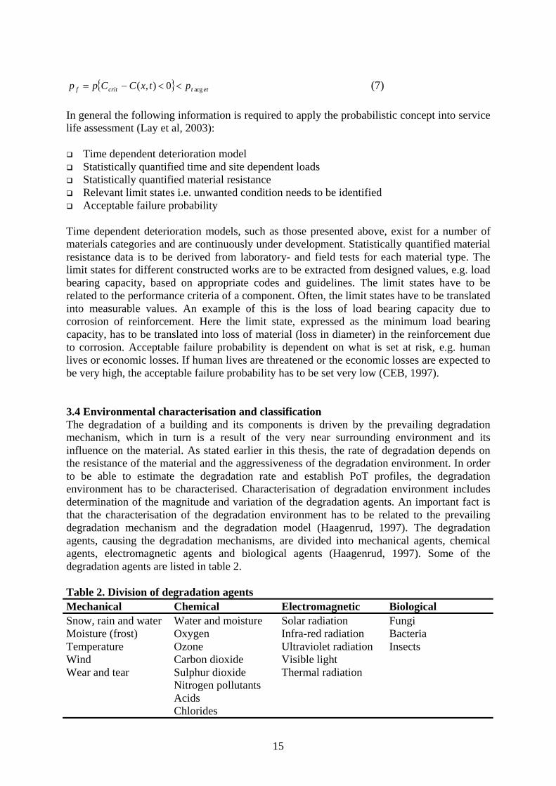
3.4 Environmental characterisation and classificationThe degradation of a building and its components is driven by the prevailing degradationmechanism, which in turn is a result of the very near surrounding environment and itsinfluence on the material. As stated earlier in this thesis, the rate of degradation depends onthe resistance of the material and the aggressiveness of the degradation environment. In orderto be able to estimate the degradation rate and establish PoT profiles, the degradationenvironment has to be characterised. Characterisation of degradation environment includesdetermination of the magnitude and variation of the degradation agents. An important fact isthat the characterisation of the degradation environment has to be related to the prevailingdegradation mechanism and the degradation model (Haagenrud, 1997). The degradationagents, causing the degradation mechanisms, are divided into mechanical agents, chemicalagents, electromagnetic agents and biological agents (Haagenrud, 1997). Some of thedegradation agents are listed in table 2.
Table 2. Division of degradation agents Mechanical Chemical Electromagnetic BiologicalSnow, rain and water Water and moisture Solar radiation FungiMoisture (frost) Oxygen Infra-red radiation BacteriaTemperature Ozone Ultraviolet radiation InsectsWind Carbon dioxide Visible lightWear and tear Sulphur dioxide Thermal radiation
Nitrogen pollutantsAcidsChlorides

16
In most cases the degradation agents act in a synergetic manner, where two or several agentsjointly cause degradation. In other cases the degradation agents have different influences onthe degradation mechanism during different phases of the degradation process. One exampleis moisture and its influence on corrosion of reinforcement due to carbonation. In the firstphase, during the carbonation process, high moisture content in the air has a protecting orretarding effect on the degradation process, while in the second phase, high moisture contenthas a rather increasing effect on the degradation process. An example of how differentdegradation agents influence each other is shown in figure 9.
Figure 9. Example of different degradation agents and their influences on each other(Westberg, 2003)
3.4.1 Transformation of environmental dataThe degradation environment at the absolute proximity of the material surface is decisive forthe degradation process (Sjöström & Brandt, 1990). The environmental conditions within thematerials, such as porous materials, are also essential for the degradation process (DuraCrete,1999). Environmental data on such levels are preferable but are, however, very rare. Sincemeasurements of micro level data are time consuming, resource absorbing and costly, othermethods of gathering environmental data is needed. Haagenrud (1997), Westberg (2003) andthe DuraCrete project (DuraCrete, 1999) discussed the possibilities of transformingenvironmental data from the macro and meso level to the local and micro level. An exactdefinition of the environmental levels does not exist. Nevertheless, Westberg (2003) used thefollowing definitions:
Global level: great parts of or the entire world Macro level: climate zone or continent Meso level: terrain area or city Local level: block Micro level: surface of a building or component
Environmental data on macro and meso levels is quite common and is available in differentdatabases. A concept, where environmental data from different databases, with other purposesthan for degradation estimations, is used in different transformation models in order tocharacterise the microenvironment, is presented in figure 10.

17
Figure 10. Schematic description of the transformation concept where thetransformation models are denoted f1, f2 and f3 (Westberg, 2003)
The environmental data on the micro level is unique since it is affected both by theenvironment on the other levels and by the indoor environment (Westberg, 2003). Theconnection between the environmental conditions at different levels and the response from thestructure is shown in figure 11.
Figure 11. Environmental conditions and the response from the structure (DuraCrete,1999)
Factors such as design, surface, orientation, topography etc. affect the microenvironment andare to be considered in the transformation modelling. There are many transformation modelsused for different purposes and of different complexity. Some of the models describe thedistribution and transformation of climatic factors and pollutants. Other models describe thedistribution and transformation of temperature and moisture from the structure (Westberg,2003). Tools based on Computer Fluid Dynamics (CFD) technique are also possible to use.Although the CFD technique requires careful modelling procedures and is computationallydemanding, the CFD technique using powerful computers is in continuous development.

18
3.4.2 Geographic Information SystemA useful tool for environmental data characterisation and gathering is the GeographicInformation System (GIS). GIS includes functions for registration, processing, storing,analysis and presentation of geographic data. The data is often visualised in maps wheredifferent layers consist of different information. The information is stored in databases andcan include information about the climate conditions, pollution etc. For visualisation andprocessing of point-based data, such as meteorological observations and measurements ofpollution, there are tools that utilise different interpolation techniques. One of them is thekriging technique. Tidblad and Kucera (2003) used the kriging technique when they presentedclimate, pollution and corrosion maps of Sweden, see figure 12. Similar corrosion maps forAustralia, Philippines, Thailand and Germany were presented by Trinidad and Cole (CIB,2000) and Anshelm et al (2000).
Figure 12. Calculated zinc corrosion after 1 year of exposure (Tidblad & Kucera, 2003)
3.4.3 Environmental classificationThe aim of environmental classification is to classify the environmental exposure relative toits severity (Haagenrud, 1997). The classification provides basic data for rough assessment ofdegradation rates and simplified predictions of service life as well as basic data whenestablishing degradation functions based on inspection data. Environmental classification issuitable as basic data for prediction of future needs of maintenance. There exists a number ofsystems for quantitative classification of environmental loads. Both the EOTA and the ISO15686-4 try to classify the exposure environment based on an overall experience of materialdegradation (Haagenrud & Krigsvoll, 2003). The standard ISO 9223 includes systems forquantitative classification of exposure environment in order to evaluate the corrosivity ofatmospheres (ISO, 1992a). The standard is a guideline including guidance for classification ofa number of degradation agents such as time of wetness (TOW), sulphur dioxide (SO2) andairborne salinity (chlorides). In the EU the governing standard for concrete structures is theEuropean Standard EN 206-1 (SIS, 2001). The standard is a harmonised European standardaimed for CE-marking of concrete. The ambition is to replace parts of the national regulationsby introducing this standard. The standard includes a number of qualitative exposure classes

19
of which one or several classes match the environment in which the concrete is intended for.Figure 13 shows how the classification system in the standard is applied on bridges exposedto de-icing salts (SCA, 2002).
Figure 13. Exposure zones of a bridge in accordance to EN 206-1 (SCA, 2002)
Zone 1 includes a splash zone where corrosion and freeze/thaw attacks due to chlorides andwater saturation constitute the decisive degradation mechanisms. In zone 2 the samedegradation agents are present. However, their impact on the bridge and its surroundings isdifferent. The Swedish Concrete Association (SCA, 2002) presents also a similar division ofexposure zones for tunnels.
To be able to estimate the degradation rate and the service life, the classification system is tobe based on a quantitative classification system. Paper II presents a proposal for a quantitativeclassification system based on EN 206-1.
4 DEVELOPMENT OF SERVICE LIFE PERFORMANCE ANALYSIS METHOD
4.1 Markov chainThe Markov chain methodology is a common approach in prediction of service lifeperformance and life cycle cost analysis. Five papers discuss the concept of Markov chainapplied in SLPA of bridges and other infrastructures. Abraham and Wirahadikusumah (1999)discussed the use of the Markov chain approach in the development of prediction models forsewerage. Jiang and Sinha (1989), Ansell et al (2001), Zhang et al (2003) and Corotis et al(2005) discussed the use of the Markov chain approach applied to bridges.
4.1.1 The basics of Markov chain in discrete timeA Markov chain is a discrete-time stochastic process with a Markov property, where theprediction of the future condition is independent of the past given the present. Consider astochastic process with the discrete-time sequence {Xn}n∈N of random variables, represented

20
within a finite discrete state space S, and where n represents the time steps within a timeperiod N. The sequence is a Markov process with Markov property if the conditionaldistribution of Xn+1 only depends on Xn, i.e. the future of the process depends only on thepresent and not the past. Mathematically the Markov property is expressed as:
( ) SjjjNnjXjX nnnnnn ∈∧∈∀== +++ 0111 ,,, KP (8)
The probability of the current state moving from one state to another or remaining in the samestate is defined by the transition probability matrix P.
⎥⎥⎥⎥
⎦
⎤
⎢⎢⎢⎢
⎣
⎡
=
mmmm
m
m
ppp
pppppp
P
K
MOMM
K
K
21
22221
11211
(9)
For a homogenous Markov chain {Xn}n∈N, the initial state vector µ(0) and the known transitionmatrix P, the state vector µ(n) is estimated according to,
nn P)0()( µµ = (10)
In order to estimate the value of the condition state E(X(n,P)), at time n, the state vector µ(n) ismultiplied by a condition-rating vector R, which refers to the condition rating scale, such as:
( )( ) RPnXE n)(, µ= (11)
The condition-rating vector R is expressed as a column vector.
A more detailed description of Markov chains and Markov properties is found in Isaacson andMadsen (1976).
4.1.2 The initial state vector There are two main factors that need to be known when establishing a discrete-time Markovchain, the initial state vector µ(0) and the transition matrix P. In general, the initial state vectordescribes the distribution of the initial condition classes. For new buildings and componentsthe initial state vector, based on a five-grade condition rating scale, is assumed to be:
( )0,0,0,0,1)0( =µ (12)
Nevertheless, sometimes the initial condition does not coincide to the designed condition. Ifso, then the initial state vector is not the same as shown in equation 12. The correct initialstate vector for new buildings can be identified at the final inspection of a new building orcomponent. In general, the state vector can be identified by condition assessment performedduring an inspection. Today, the condition assessment of a building or a component oftenrefers to only an assessed “mean” condition class, whereas it would be more convenient toassess the distribution of the different condition classes.

21
4.1.3 The transition matrixThe transition matrix describes the probability of change in condition. In the case ofdegradation, where it is assumed that the condition will get worse over time, the transitionmatrix describes the probability of a condition state to either be in the same state or move to aworse state. The crucial part is to define the transition matrix and find these probabilities.Paper III describes a method where the transition matrix is determined based on a knowndegradation function. The method is discussed by Jiang and Sinha (1989), Abraham andWirahadikusumah (1999) and Ansell (2001). Thompson and Johnson (2005) present a methodhow to determine the transition matrix based on inspection data.
Assume that a known degradation function is denoted Y(n), then
( )( ) )(, nYPnXE ≅ (13)
where n is the time, P is the transition matrix.
The elements, pij, in the transition matrix, P, are determined numerically by an iterativeprocess such as the sum of the differences between the known degradation function Y(n) andthe Markov chain function E(X(n,P)) is minimised, see eq. 14.
( )( )∑=
−N
n
PnXEnY1
,)(min (14)
where each transition matrix is valid in the respective time period N, see figure 14.
Figure 14. The transition matrixes are determined by the minimisation problem for eachtime period Ni

22
This numerical minimisation routine is of the type trial and error. The way of solving theproblem is simple but quite time consuming and computationally demanding for small timesteps. Ansell (2001) suggested a more sophisticated method such as a Quasi-Newton method.The disadvantage of such a method is that it may cause some convergence problems.
4.2 Residual service life Information about the residual service life of buildings and building parts is of special interestfor optimal MR&R planning. Brandt et al (1999) developed a method called “Méthoded’Evaluation de scénarios de Dégradation probables d’Investissements Correspondants(MEDIC)” in order to assess the residual service life. The method builds upon the theories ofconditional probabilities and calculates the residual service life as a probability distribution.The probability distribution of condition classes of a building or a building part could bebased on measurement data, inspection data or simulations, where the simulations are basedon the Markov chain model. Figure 15 shows a cumulative probability distribution ofcondition classes based on simulations.
Figure 15. Cumulative probability distribution of condition classes
The conditional probability space, Q = {0,1}, or “quality space” as defined by Brandt et al(1999) describes the distribution of the condition classes at any time within the time period. Abuilding close to Q = 0 is of good quality while a building close to Q = 1 is of poor quality.Assume that the condition class of a building or a building part q, q ∈ Q, at time t is known,then it is possible to estimate the maximum, minimum and mean residual service life asshown in figure 16.

23
Figure 16. Minimum, maximum and mean residual service life
The letter B, marked in figure 16, is the maximum possible “quality” limit of the building orbuilding part. If q ∈ {B,1}, then the conditional probabilities give:
{ }( ) ( ) ( )( )BP
BPCCPBqCCP ti
ti −
−=∈
11, ,
, (15)
where CCi,t is condition class i at time t and i∈S.
4.3 Service life performance analysis modelThe aim of the developed SLPA model, presented in paper III and further discussed in thisthesis, is to set the scene for a uniform SLPA approach based on advanced degradationfunctions as well as inspection data. The Markov chain model and the MEDIC method,described in section 4.1 and 4.2 respectively, are used together to serve as a methodologicalrectifier in order to provide uniform output data for further analysis of maintenance needs, seefigure 17. The model is developed to manage different kind of SLPA approaches on bothobject level and network level.

24
Figure 17. Schematic description of the processes in the SLPA model
The model is open and can be applied on any type of constructed work with a conditionalbased classification system. Paper III shows how the model is applied to a bridge managementsystem.
5 SERVICE LIFE PERFORMANCE ANALYSIS
The performance of SLPA is restricted to the available information on material, product andenvironmental characteristics, but also to user requirements. This section of the thesis presentstwo approaches of SLPA with different degrees of detail applied to different material families.The first approach is based on the international standard ISO 9223, where classification of thedegradation environment is essential. The analysis gives a broad picture of the futureperformance of metals due to the atmospheric corrosivity and is appropriate on a networklevel. The second approach is based on the SLPA model presented in section 4.3 and isfurther discussed in paper III.
5.1 Service life performance analysis of metals based on ISO 9223The international standard ISO 9223 (ISO, 1992a) is used in this thesis in order to evaluate thecorrosivity of the atmosphere on carbon steel and zinc in Gävle. The evaluation process isbuilt on characterisation and classification of a number of essential environmental factors.

25
Each step in evaluation process is presented. The data used in the evaluation process is basedon climatic data and pollution data from the Swedish Meteorological and HydrologicalInstitute (SMHI).
5.1.1 Time of WetnessThe influence of moisture on the corrosion process is characterised by the Time of Wetness(TOW). TOW is defined according to ISO 9223 as:
“…The length of time when the relative humidity is greater than 80 % at atemperature greater than 0° C…”
The characteristic TOW for Gävle is 3500 hours/year. This refers to TOW class τ4, grey-marked in the upper right corner of figure 18.
Figure 18. Classification of corrosivity (ISO, 1992a)
5.1.2 Atmospheric pollution The data on sulphur dioxide (SO2) is based on the web-based MATCH-model by SMHI(SMHI, 2003). Local sources are neglected. Airborne salinity data has not been available,however, based on expertise, it is assumed that deposition of airborne salinity is low, i.e. < 15mg/m2/day. The pollution data for Gävle is presented in table 3.

26
Table 3. Pollution data for Gävle (SMHI, 2003)Pollution Concentration Pollution classSulphur dioxide (SO2) 0,4-0,6 µg/m3 P0
Airborne salinity < 15 mg/m2day S1
The pollution class P0 is grey-marked horizontally at the lower part of figure 18. The pollutionclass S1 is grey-marked vertically in figure 18.
5.1.3 Corrosivity classDerivation of the corrosivity of the atmosphere is based on the environmental classification ofTOW and the pollution substances described above. The corrosivity class is defined as C3,marked in figure 18. The corrosivity class C3 is transformed into corrosion rates of carbonsteel and zinc. The corrosion rate during the first year of exposure is defined rcorr1. Thecorrosion rate during the first year of exposure is also recalculated and presented as rcorr2. Thecorrosion rate after 10 year of exposure, defined as rlin, is considered to be constant (ISO,1992b). The corrosion rate, defined as rav, during the first 10 years is not constant. Thecorrosion rate is, however, presented as average values. The result of the evaluation of thecorrosivity of the atmosphere is summarised in table 4.
Table 4. Corrosion rates of carbon steel and zinc considering corrosivity class C3Metal rcorr1 (g/m2a) rcorr2 (µg/a) rav (µm/a) rlin (µm/a)Carbon steel 200 - 400 25 – 50 1.5 - 6 5 – 12Zinc 5 - 15 0.7 – 2.1 0.5 - 2 0.5 – 2 Corrosion over time for carbon steel and zinc, based on the result in table 3, is presented infigure 19 and 20.
Figure 19. Corrosion over time for carbon steel in corrosivity class C3

27
Figure 20. Corrosion over time for zinc in corrosivity class C3
5.2 Service life performance analysis based on Markov chain model and MEDIC methodThe following example shows the results form an application of the SLPA model to woodenwindows. The aim of the example is to show the model’s applicability on components andmaterials other than those presented in paper III. In this case the basic data is taken from theMOBAK study (Tolstoy et al, 1990). The data is processed and transformed into condition-over-time functions. The result is presented in figure 21.
Figure 21. Condition development of wooden windows
The condition rating system of the MOBAK study is based on a three-grade rating systemwhere 0 = intact, 1 = minor damages and 2 = repairs advisable. There are, however, manyother types of rating system. In this example, a five-grade rating system is used. Therefore thecondition-over-time function based on the MOBAK rating system is transformed into a five-

28
grade rating system. The new function is applied to the Markov model described in section4.1.3 and to the MEDIC method described in section 4.2. The result of the calculations,assuming ten-year-old windows of condition class 3, is presented in figure 22.
Figure 22. Condition class distribution of windows in a north facade
In this case the residual service life is estimated to minimum 3 year, maximum 15 year andmean 8 year.
6 DISCUSSION AND CONCLUSIONS
The LMS and other similar predictive maintenance management systems are aimed to supportdecision-makers and engineers in their effort to achieve a more effective and life cycle basedmaintenance management. LMS is an open and integrative system, which has to be adaptedand developed in order to meet the needs and requirements of users, and where systemintegration and organisational development are core issues. This process is to be geared andgoverned by the user. The system includes management of inventory and inspection data, andalso functions for simulation for future performance and life cycle optimisation ofmaintenance. These life cycle simulations require systems for characterisation and registrationof objects and their components. It is thus not enough to just characterise and register thoseobjects and components that are currently inspected, but the whole network of objects andcomponents are to be included. Characterisation includes design, material and environmentalaspects that may have influence on future conditions. The Swedish BMS is a well-developedmanagement system that includes systematic registration of the overriding information ofobjects. The system lacks predictive functions for SLPA and systematic characterisation ofdesign, material and environmental parameters on a component level. The degradationmodels, presented in this thesis, show some of the needed data and data format for simulationof future performance. Although the material and environmental data is, in most cases,available, there is a lack of registered data in the system. This in turn makes it difficult to usethe degradation models effectively. Nevertheless, it would be possible, by rather small means,to develop the existing BMS into a system including systematic characterisation and

29
registration of components, their design and material parameters and also the exposureenvironment. The burdensome work will consist of collection and registration of the data.
Development of degradation functions and models based on inspection data, as discussed inpaper III, may be an appropriate complement to existing degradation models. It should bementioned that many of the existing degradation models are only valid to certain conditions.At this point it might be more convenient to base the SLPA on historical inspection data.However, this study has found some difficulties in developing degradation models based oninspection data. These difficulties are mainly due to data quality and lack of availableexplanatory factors. For example, the inspection data may include incomplete informationabout former maintenance actions, i.e. when, where and how the actions are performed. Thislack of information makes it difficult to describe the degradation properly. Thompson andJohnson (2005) make similar conclusions when it comes to the development of degradationmodels based on historical inspection data. Some of the data is also prone to subjectiveassessment. Discussions with inspectors indicate that some assessments are influenced by thebudget restrictions. The type of condition rating scale, such as the one in the Swedish BMS,where the condition classes refer to the residual service life rather than to the currentcondition, is also an issue for discussion. The Swedish condition rating scale presupposes thatthe inspector possess skills in assessing the residual service, which thus also includesknowledge about degradation rates. A proper assessment of the residual service life could bedifficult without any supporting SLPA tool. To base the development of a degradationfunction on such premises cause false description of degradation. Condition rating scales,referring to the actual condition, are preferable. Furthermore, the lack of available materialand environmental data makes it difficult to develop inspection-data-based degradationfunctions that include material and environmental explanatory factors. The possibilities ofdeveloping degradation functions, including material and environmental explanatory factors,are dependent on the characterisation and registration of objects.
Whether the Markov chain method and the determination of transition probability matrixbased on advanced degradation models is appropriate or not, is a question for discussion. Theaim of the method is to provide a uniform conditional probability based expression of thedegradation. But is this necessary? Are there any possibilities to use different approacheswithout time-wasting transformations? There is the reliability approach, which is preferable.However, the reliability approach requires statistically quantified data on material resistancesand environmental loads. Such data is not always available.
The information about residual service life is an essential outcome of the SLPA. Thisinformation is an important input to MR&R analysis and optimisation. The MEDIC methodseems to be a simple method for calculation of the residual service life. However, the methodincludes an interesting question. How does a given condition quality space for a certainconstruction work or part thereof change over time? This is a subject for furtherinvestigations.
The utilisation of standards that include systematic characterisation and classification ofmaterial and environmental properties has several benefits in SLPA. The standards are oftenknown to the user, which facilitates the use of the standard in SLPA. The standards are oftenapplied in the design phase; therefore information gained when using the standards isappropriate in SLPA. An example of this is the European standard EN 206-1, which is used inthe design phase in order to determine the concrete composition. However, quantitativecharacterisation and classification of material and environmental properties is a prerequisite

30
for using the standards in SLPA. The international standard ISO 9223 includes quantitativecharacterisation and classification of material and environmental properties, the Europeanstandard EN 206-1 does not. Development of a quantitative environmental classificationsystem in EN206-1 is discussed in paper II. The use of the international standard ISO 9223gives a very broad picture of the future performance of metals. The standard is, however,simple to use and is appropriate on a network level and as a complement to dose-responsefunctions.
Characterisation of the degradation environment is essential in order to be able to usedegradation models and standards, such as ISO 9223. The characterisation is governed by theacting degradation mechanisms and the applied degradation models. In the example,presented in section 5.1, the characterisation of pollutants is partly based on data from theMATCH-model of SMHI. The model gives an overriding picture of the deposition of anumber of pollutants. However, the deposition from local sources is not taken into account.The impact from local sources is considerable and must be taken into consideration in order togive a correct description of the degradation. The model does not take into account the drydeposition of chlorides from the atmosphere. There is thus a need to develop and adaptenvironmental data models for SLPA.
7 RESEARCH AND DEVELOPMENT NEEDS AND FUTURE WORK
Long-term optimisation and planning of MR&R actions becomes more and more important.The current reactive approach of maintenance management is therefore changing towards apredictive approach where the knowledge of material property and degradation environmentis essential. This change of current reactive practice towards a predictive approach requiressystems that are capable of managing large amount of information of the constructed works,their material properties and the degradation environment. The constructed works have to bemaintained during their whole service life, an activity for which the maintenance managerorganisation is responsible. The maintenance manager organisations are of different size, withvarious funding and MR&R strategies. Some managers operate facility management systems,in which they handle information about the constructed works, some do not. The changetowards a predictive approach requires generic systems, applicable to different maintenancemanager organisations with different MR&R strategies, managing different types ofconstructed works. Generic is to be interpreted so that either the systems as a whole areprogrammed to establish customised client versions, or that single part of the systems areadapted to be incorporated with existing facility management systems in use by the clients.The current LMS is a predictive and generic maintenance management system applicable forany constructed works. The development of the LMS as a maintenance management system isbased on existing structures. In the last project the LMS was developed with specific regard toconcrete structures. At present there is an on-going project with the aim to develop a LMSpilot for hospitals. The project will be completed in 2006. The LMS should be furtherdeveloped to a complete ICT-tool for service life planning and MR&R planning of anyconstructed works, in operation from the beginning of the design process. Such a LMSversion would support the necessary quality assurance activities in the design process, whileoffering a life cycle management assets to the facility manager when the construction work istaken into operation.

31
The generic characteristic of LMS offers flexibility and adaptability, where the user needs andrequirements are met in every implementation and application of the system. The future workwill therefore include adaptation and development of the whole system or just some modulesof the system and the methodology and the systematic therein. The R&D needs should mainlyaddress:
Further development of methodology and systems for data gathering and data recording Systematic evaluation of MR&R performance Further R & D of existing degradation models as well as development and establishment
of new models Further development of systems for characterisation of degradation environment,
including development of transformation models Further development of environmental classification systems including development of
existing standards, such as EN 206-1 Development of LMS as a design and quality assurance supporting tool
Finally, the development of the Industry Foundation Classes (IFC) offers great possibilitiesfor effective communication between ITC tools. The future implementation of the IFCstandard into the LMS, will, above all, make the recording and handling of data moreeffective, and thus save money to the user.

32
REFERENCES
Abraham, D.M. and Wirahadikusumah, R., (1999) ‘Development of prediction models forsewer deterioration’, Proceedings of the 8th International Conference on Durability ofBuilding Materials and Components, Vancouver, May 1999, National Research Council, p.1257-1267
Aikivuori, A.M., (1999) ‘Critical loss of performance – what fails before durability’Proceedings of the 8th International Conference on Durability of Building Materials andComponents, Vancouver, May 1999, National Research Council, p. 1369-1376
Ansell, A., (2001), ‘Numerical calculation with Markov chains in condition developmentmodels for bridge elements’, (in Swedish), Technical report 2001:12, The Royal Institution ofTechnology, Stockholm
Ansell, A., Racutanu, G. and Sundquist, H., (2001), ‘A Markov approach in estimating theservice life of bridge elements in Sweden’ Proceedings of the 9th International Conference onDurability of Building Materials and Components, Brisbane, March 2002, CSIRO BCE, paperno. 142
Anshelm, F., Gauger, Th., Köble, R., Mayerhofer, P. and Droste-Franke, B., (2000),‘Mapping actual corrosion rates and exceedances of acceptable corrosion rates procedure andresults’, Proceedings of a UN ECE Workshop, Stockholm, Sweden, June 14-16, 2000,Swedish Corrosion Institute, Bulletin 108E. Stockholm, p. 27-40
BBR 2002, (2002), ‘Building Regulations: Mandatory provisions and generalrecommendations’, Swedish Board of Housing, BFS 2002:19, edition 4:1, September 2002
Bourdeau, L., (1999), ‘Sustainable development and the future of construction: a comparisonof visions from various countries’, Building Research and Information 1999, vol. 27, No. 6, p.355-367
Brandt, E., Flourentzou, F. and Wetzel, C., (1999), ‘MEDIC – A method for predictingresidual service life and refurbishment investment budgets’, Proceedings of the 8th
International Conference on Durability of Building Materials and Components, Vancouver,May 1999, National Research Council, p. 1280-1288
Burström, P. G., (2001), ‘Building materials’, Studentlitteratur, ISBN 91-44-01176-8, onlyavailable in Swedish
CEB, (1997), ‘New Approach to Durability Design – An example for carbonation inducedcorrosion’ Bulletin No. 238
CIB, (2000), ‘GIS and the built environment’, CIB Report publication 256, CIB/TG20,editors: Haagenrud, S.E., Rystedt, B. and Sjöström, C.
Corotis, R. B., Ellis, J. H. and Jiang, M., (2005), ‘Modelling of risk-based inspection,maintenance and life-cycle cost with partially observable Markov decision processes’Structure and Infrastructure Engineering, 2005, vol. 1, No. 1, p. 75-84

33
DuraCrete, (1999), ‘Models for environmental actions on concrete structures’ Brite EuRamIII, Document BE95-1347/R3, March 1999
EOTA, (1999), ‘Assumption of working life of construction products in Guidelines forEuropean Technical Approval’, European Technical Approvals and Harmonised Standards,Guidance Document 002, European Organisation for Technical Approvals, December 1999
EU, (1988), ‘Council Directive 89/106/EEC of 21 December 1988 on the approximation oflaws, regulations and administrative provisions of the Member States relating to constructionproducts’, The Council of the European Communities, 1988, Brussels
EU, (2002), ‘Interpretative Documents No. 1: Mechanical resistance and stability’, lastupdated 2002-07-08, http://europa.eu.int/comm/enterprise/construction/ 2005-06-10
Gehlen, C. (2000), ‘Probabilistische Lebensdauerbemessung von Stahlbetonbauwerken’ (inGerman), Deutscher Ausschuss für Stahlbeton, Heft 510, Beuth Verlag GmbH, Berlin
Haagenrud, S. E. and Krigsvoll, G., (2003), ’Instructions for quantitative classification ofenvironmental degradation loads onto structures’, Lifecon G1RD-CT-2000-00378 LifeconDeliverable D 4.2, Final Report, Public usage
Haagenrud, S. E., (1997), ‘Environmental Characterisation including Equipment forMonitoring’, CIB W80/RILEM 140-PSL, (Norwegian Institute for Air Research – NILU,Kjeller, 1997)
Haagenrud, S., Stordahl, P., Eriksson, B., Riks, E., Krigsvoll, G. and Garofolo, I., (2001),‘System for Maintenance Management of Historic (Wooden) Buildings’ (acronym:MMWood), Final report, EU-Project ENV4-CT98-0796
Haagenrud, S., Veit, J., Eriksson, B., Henriksen, J. F. and Krigsvoll, G., (1999), ‘System andMethods for Assessing Conservation State and Environmental Risks for Outer Wooden Partsof Cultural Buildings’ (acronym: Wood-Assess), Final Report, EU-project ENV4-CT95-0110
Henriksen, J. F., (2004), ‘Field exposure, dose-response functions, monitoring andcharacterisation of the degradation environment’, (in Norwegian), reference no. Q-303, NILUF14/2004, Norwegian Institute for Air Research – NILU, Kjeller
Horner, R.M.W., El-Haram, M.A. and Munns, A.K., (1997), ‘Building maintenance strategy:a new management approach’, Journal of Quality in Maintenance Engineering, vol. 3 no.4, p.273-280
Isaacson, D. L. and Madsen, R. W., (1976), ‘Markov Chains Theory and Applications’, JohnWiley & Sons, New York
ISO, (1992a), ‘ISO 9223, Corrosion of metals and alloys – Corrosivity of atmospheres –Classification’, Ref no. ISO 9223:1992(E), The International Organization forStandardization, Genéve

34
ISO, (1992b), ‘ISO 9224, Corrosion of metals and alloys – Corrosivity of atmospheres –Guiding values for the corrosivity categories’, Ref. no. ISO 9224:1992(E), The InternationalOrganization for Standardization, Genéve
ISO, (2000), ‘ISO 15686-1, Buildings and constructed assets- Service life planning part 1:General principles’ Reference number ISO 15686-1:2000(E)
Jiang, Y. and Sinha, K. C., (1989), ‘Bridge service life prediction model using Markov chain’,in Transportation Research Record 1223, Transportation Research Board, National ResearchCouncil, Washington D.C., p. 24-30
John, V.M., Sjöström, C. and Agopyan, V., (2002), ‘Durability in the built environment andsustainability in developing countries’ Proceedings of the 9th International Conference onDurability of Building Materials and Components, Brisbane, March 2002, CSIRO BCE, paperno. 011
Lay, S., Schieβl, P. and Cairns, J., (2003), ‘Service Life Models’ Lifecon G1RD-CT-2000-00378 Lifecon Deliverable D 3.2, Final Report, Public usage
Lerfald, B. O. and Sund, E. K., (2003), ’Vegkapital – Litteraturundersökelse’ (in Norwegian),SINTEF Rapport, Report no. STF22 A03311, Statens Vegvesen
Marteinsson, B., (2005), ‘Service Life estimations in the design of buildings – A developmentof the Factor Method’ doctoral thesis, KTH – HIG, April 2005, Gävle, Sweden
MIEC, (2003), ‘Transport Policy for sustainable development’, Article no. N3047, Ministryof Industry, Employment and Communications, Stockholm, November 2003
Neville, A.M. (1995), ‘Properties of concrete’, 4th edition, Longman, Harlow
Patermann, C., (1999), ‘The fifth EU framework programme and its consequences for theconstruction industry’, Building Research and Information 1999, vol. 27, No. 6, p. 413-419
PBL, (1987), ‘Planning and Building Act’, Ministry of Sustainable Development, SFS1987:10, http://rixlex.riksdagen.se, 2005-07-28
Racutanu, G., (2000), ‘The Real Service Life of Swedish Road Bridges – A case study’,Doctoral Thesis, KTH TRITA-BKN Bulletin 59, The Royal Institute of Technology,Stockholm
REHABCON, (2004), ‘REHABCON Manual’, Innovation and SME Programme, IPS-2000-0063
Sarja, A., (2004), ‘Life Cycle Management System – LIFECON LMS, Technical summary’,Lifecon G1RD-CT-2000-00378, Public usage
Sarja, A. and Vesikari, E. (editors), (1996), ‘Durability Design of Concrete Structures’,Report of RILEM TC130-CSL, E&FN SPON, London

35
SCA, (2002), ‘Vägledning för val av exponeringsklass enligt SS-EN 206-1’, (in Swedish),Swedish Concrete Association, Report no. 11
Shepard, R.W., (2005), ‘Bridge management issues in a large agency’, Structure andInfrastructure Engineering, accepted 9 June 2004
SIS, (2001), ‘SS-EN 206-1 2000, Concrete – Part 1: Specification, performance, productionand conformity’, Swedish Standards Institute, Ref. no. EN 206-1:2000 Sv.
Sjöström, C. and Brandt, E., (1990), ‘Collection of in-service performance data: State of theart and approach by CIB W80/RILEM 100-TSL’ Proceedings of the 5th InternationalConference on Durability of Building Materials and Components, Brighton, November 1990,E&FN. SPON, p. 287-298
Sjöström, C., (2001), ’Approaches to sustainability in building constructions’, StructuralConcrete 2001, vol. 2, No. 3, p. 111-119
Sjöström, C. and Bakens, W., (1999), ‘CIB Agenda 21 for sustainable construction: why, howand what’, Building Research and Information 1999, vol. 27, No. 6, p. 348-354
SMHI, (2003), http://smed.smhi.se/website2/MATCH_mo_tdse/main.htm, 2003-12-05
SRA, (1996a), ‘Bridge – Measurement and Condition Assessment’, SRA publication1996:038 (E), Borlänge, Sweden
SRA, (1996b), ‘Bridge - Inspection Manual’, SRA publication 1996:036 (E), Borlänge,Sweden
SRA, (2004), ‘Vägar och gators utformning, VGU’, (in Swedish), SRA publication 2004:80Borlänge, Sweden
Svensson, K., (1998), ‘Integrating Facilities Management Information – A process andproduct model approach’ Doctoral thesis, KTH, Stockholm
Thoft-Christensen, P., (1998), ‘Assessment of the reliability profiles for concrete bridges’Engineering Structures, 1998, vol. 20, No. 11, p. 1004-1009
Thompson, P. D. and Johnson, M. B., (2005), ‘Markovian bridge deterioration: developingmodels from historical data’, Structure and Infrastructure Engineering, vol. 1, No. 1, p. 85-91
Tidblad, J. and Kucera, V., (2003), ‘Mapping areas in Nordic countries with evaluated risk ofatmospheric corrosion – Methodology development and mapping on a 20 km x 20 km grid forSweden’ KI report 2003:4E, Swedish Corrosion Institute, Stockholm
Tolstoy, N., Andersson, G., Sjöström, C. and Kucera, V., (1990), ‘External building materials– quantities and degradation’, Research report TN:19, The National Swedish Institute forBuilding Research, Gävle, Sweden
Tuutti, K., (1982), ‘Corrosion of steel in concrete’, Swedish Cement and Concrete ResearchInstitute, Stocholm

36
Van Noortwijk, J. M. and Frangopol, D.M., (2004), ‘Deterioration and maintenance modelsfor insuring safety of civil infrastructures at lowest life-cycle cost’, Life-Cycle Performance ofDeteriorating Structures: Assessment, Design and Management, American Society of CivilEngineers, Reston, Virginia, p. 384-391
WCED, (1987), ‘Our common future – Brundtland Report’, World Commission onEnvironment and Development, UN, General Assembly No.A/42/427, August 1987
Westberg, K., (2003), ‘Use of available climate and environmental data in service lifeassessments of buildings’, (in Swedish), Licentiate thesis, KTH, Stockholm
Zhang, Z., Sun, X. and Wang, X., (2003), ‘Determination of bridge deterioration matriceswith State National Bridge Inventory Data’ Proceedings of the 9th International BridgeManagement Conference, Orlando, April 2003, Transportation Research Board, p. 207-218