development and application of a polarimetric x-band radar for mobile or
TRANSCRIPT

DEVELOPMENT AND APPLICATION OF A POLARIMETRIC X-BAND RADAR FOR MOBILE OR STATIONARY APPLICATIONS
Joerg Borgmann*, Ronald Hannesen, Peter Gölz and Frank Gekat
Selex-Gematronik, Neuss, Germany Renzo Bechini and Roberto Cremonini
Arpa, Piemonte, Italy
1. INTRODUCTION
Modern polarimetric radars offer enhanced
capabilities for rain attenuation correction, rain rate estimation and precipitation classification (e.g. Bringi et al, 2001). In the past a few re-search radars were developed to investigate polarimetric radar performance (e.g. Brooks et al, 2001). Based on these results and simula-tions new algorithms were developed to verify more accurately the rain rate from the measured polarimetric variables (e.g. Testud et al, 2000, e.g. Le Bouar et al, 2002). These systems capa-bilities applied to X-Band radars lead to systems, which are of interest for hydrology and radar networks. Smaller size and reduced cost for these systems are ideal for mobile and gap filler applications in radar networks.
Selex SI GmbH developed a polarimetric X-band radar system, which has the same general parameters and software interfaces as large scale C- or S-band radars. This radar is mounted on a trailer for mobile application (Fig-ure 1) or can be operated in a fixed installation e.g.on a roof. The system can be operated with and without radome, which makes it ideal for high quality polarimetric measurements. The technical details and first results of the mobile radar version are presented.
2. TECHNICAL DETAILS The radar was designed to cover several dif-
ferent applications. Only X-band radars are suit-able for mobile applications since they offer the best compromise between antenna size and angular resolution. For radar networks the data quality should be comparable to the other radars
in the network. Hydrologic applications need
reliable rain rate estimates. Due to that the radar was designed for comparable performance like antenna positioning time, velocity and different beam width. Table 1 shows the general available reflector characteristics. The values are compa-rable to C- and S-.band radars. Table 1: Reflector characteristics for the 3 different reflector sizes Antenna XDP20 XDP15 XDP10 Operating freq. range 9.3 - 9.6 GHz Freq. - factory default 9.375 GHz Calibration freq. range 9.3 - 9.6 GHz Reflector diameter 1.2 m 1.8 m 2.4 m Beamwidth at -3 dB < 2° < 1.35° < 1.05° Polarization linear horizontal and vertical Power gain > 38.5dB > 42dB >44,5dB Min. first sidelobe level < -23dB < -25dB < -27dB The control components RCP (Radar control processor) and the signal processor (GDRX) are already used in the Meteor 1600/600 C+S band radars. Due to that the radar control is software compatible. The meteorological post processing is done with the dual polarisation version of the Rainbow 5 software. This software configuration allows the simple integration in existing radar networks. Existing volume scans sets for net-works can be applied. For maintenance and
Figure 1: Mobile trailer radar attached to the towing vehicle. The weight of the trailer is 2.8 tons including radome.
P10.13
* Corresponding author address: Jörg Borgmann, Selex-Gematronik, Raiffeisenstr. 10, 41470 Neuss, Germany; e-mail: [email protected]
calibration the standard Ravis software can be used. The signal processing hardware allows all modern signal processing algorithms like DFT clutter filtering, 2nd trip recovery and dual PRF algorithms (e.g. GDRX manual 2005).
To keep the design compact all radar com-ponents are placed at the elevation level and no rotary joints are used for the waveguide. This has the advantage that there are no long term effects due to the rotary joints aging and no leak-age for operation without radome. Figure 2 shows the general setup of the radar. The sys-tem components are mounted over elevation at the side arms below the reflector. The boxes are hermetically closed and cooled.
Due to the design the waveguide to the reflector has only 1m length, keeping losses to an abso-lute minimum. The general technical data of the radar hardware components are listed in Table 2. The system is magnetron based. The full co-herent receiver design allows a klystron, TWT or solid state transmitter as well. 2.1 STATIONARY INSTALLATION
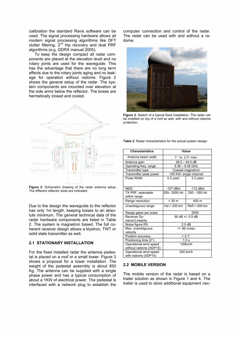
For the fixed installed radar the antenna pedes-tal is placed on a roof or a small tower. Figure 3 shows a proposal for a tower installation. The weight of the pedestal assembly is about 850 Kg. The antenna can be supplied with a single phase power and has a typical consumption of about a 1KW of electrical power. The pedestal is interfaced with a network plug to establish the
computer connection and control of the radar. The radar can be used with and without a ra-dome.
Table 2: Radar characteristics for the actual system design
Characteristics Value
Antenna beam width 1° to 2.0° max. Antenna gain 38.5 – 44.5 dB Operating freq. range 9.36 – 9.38 GHz Transmitter type Coaxial magnetron Transmitter peak power >55 KW, single channel Pulse Width 0.3 µsec 3.3 µsec
MDS -107 dBm -112 dBm TX PRF, selectable within range
250– 3000 Hz 250 – 550 Hz
Range resolution < 30 m 450 m Unambiguous range Vel.> 200 km Refl.> 400 km
Range gates per pulse 2500 Receiver Dy-namic/Linearity
90 dB +/- 0.5 dB
Noise figure RX 2.5 dB Max. unambiguous velocity
+/- 96 m/sec
Position accuracy < 0.1° Positioning time (2°) 1.5 s Operational wind speed without radome (XDP15)
120km/h
Operational wind speed with radome (XDP15)
200 km/h
2.2 MOBILE VERSION
The mobile version of the radar is based on a trailer solution as shown in Figure 1 and 4. The trailer is used to store additional equipment nec-
Figure 2: Schematric drawing of the radar antenna setup.The different reflector sizes are indicated.
Figure 3: Sketch of a typical fixed installation. The radar can be installed on top of a roof as well, with and without radome protection.

cessary for mobile operation like generator, ad-ditional computer equipment and air condition.
In the trailer there is an additional cabinet with computer equipment, a Rainbow computer, GDRX-Signal Processor and WLAN Router, which allows the storage of additional equip-ment. The air condition is used to cool/heat the radome and the additional equipment. The ra-dome can be lifted mechanically for mainte-nance work or can be removed completely for operation without radome as shown in Figure 4. 3. RESULTS The radar was setup in Piemonte, Italy in March 2007 and tested at Selex-Gematronik before. Due to the use of the standard GDRX digital receiver and signal processing equipment it is possible to record high quality data and use the possibilities for dual polarisation evaluation. It was possible to record clear air data up to 30km and analyze some precipitation events close to the Alps. Figure 5 and 6 show the data of the same thunderstorm event at different time. The core of the storm can be clearly identified.
Figure 5: PPI-scan of a local thunderstorm at Carmagnola near Piemonte, Italy.
Figure 4: Trailer radar without radome installed. For standard setup the trailer is mounted on support feeds. The alignmentfor operation is done by mechanical leveling (0.05°), built in GPS and solar calibration.

Figure 7: RHI-scan generated from volume data of a thunderstorm at Carmagnola near Piemonte, Italy. In this plot the core of the storm cell can be clearly seen.
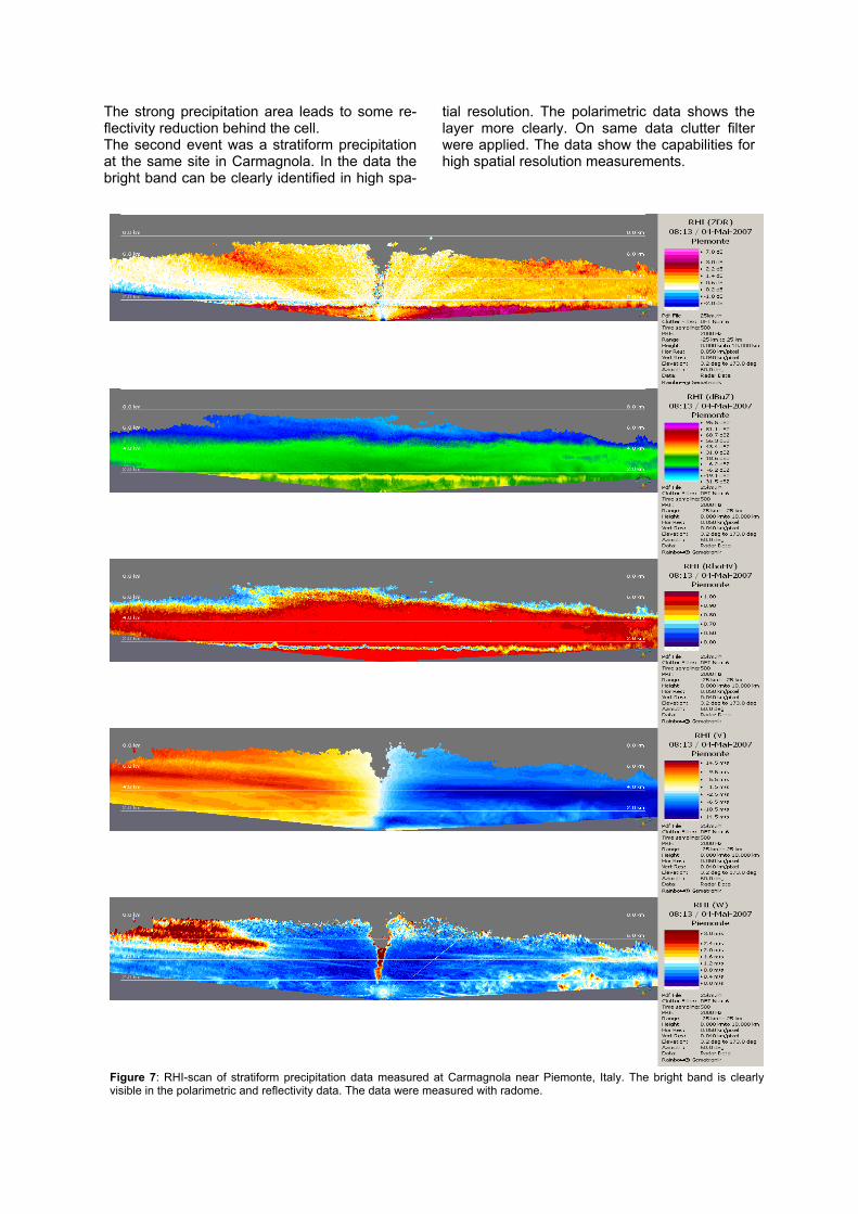
Figure 7: RHI-scan of stratiform precipitation data measured at Carmagnola near Piemonte, Italy. The bright band is clearly visible in the polarimetric and reflectivity data. The data were measured with radome.
The strong precipitation area leads to some re-flectivity reduction behind the cell. The second event was a stratiform precipitation at the same site in Carmagnola. In the data the bright band can be clearly identified in high spa-
tial resolution. The polarimetric data shows the layer more clearly. On same data clutter filter were applied. The data show the capabilities for high spatial resolution measurements.

4. SUMMARY AND OUTLOOK A new x-band based polarimetric radar has
been successfully demonstrated. The measured data are of high resolution and ideal for short range investigation and research. The mobile platform allows fully independent remote opera-tion and enhanced interfaces for further algo-rithm development. First measurements with the performance were shown, which demonstrate the general performance. The performance and long term operation stabil-ity and polarimetric calibration will be further analysed. Other topics for further analysis are:
• The systematic measurement of the po-
larimetric performance with and without ra-dome under different environmental condi-tions.
• The bias of the polarimetric variables for X-band due to environment .
• Comparison of data measured with a C-band polarimetric radar at the same location.
5. REFERENCES
Bringi, V. and V. Chandrasekar, 2001: Po-larimetric Doppler Weather Radar: Principles and Applications. Cambridge University Press, 636 pp.
Brooks E. Martner, Kurt A. Clark, Sergey Y. Ma-
trosov, W.Carroll Campbell, and Janet S. Gibson NOAA/ETL’s POLARIZATION-UPGRADED X-BAND “HYDRO” RADAR 30th Intl. Conf. on Radar Meteor. Munich 2001
GDRX Receiver and Signal Processor Manual Selex SI GmbH, Neuss, Germany 2005
Le Bouar, E, J. Testud and S. Y. Matrosov,
2002: Rainfall rate estimate from the rain pro-filing algorithm “ZPHI” applied to X-band po-larimetric radar data. Proc. European Conf. Radar Meteor., November 2002, Delft, Neth-erlands, 238-242.
Testud, J., E. Le Bouar, E. Obligis, and M. Ali-
Mehenni, 2000: The rain profiling algorithm applied to polarimetric weather radar. J. At-mos. Oceanic Technol., 17, 332 – 356.