development and demonstration of a wood-fired gas turbine...
TRANSCRIPT
DOEIMC/30127 -- 5790 (DE97005487)
Development and Demonstration of a Wood-Fired Gas Turbine System
Topical Report March 1,1995 - March 31,1996
RECEIVED OCT 2 3 a? By:
Vijay Sethi OBTJ
Work Performed Under Contract No.: DE-FC21-93MC30127
For U.S. Department of Energy
Office of Fossil Energy Federal Energy Technology Center
Morgantown Site P.O. Box 880
Morgantown, West Virginia 26507-0880
BY Western Research Institute
365 North Ninth Street Laramie, Wyoming 82070
u-3 ex3 0

Disclaimer
This report was prepared as an account of work sponsored by an agency of the United States Government. Neither the United States ‘Government nor any agency thereof, nor any of their employees, makes any warranty, express or implied, or assumes any legal liability or responsibility for the accuracy, completeness, or usefulness of any information, apparatus, product, or process disclosed, or represents that its use would not infringe privately owned rights. Reference herein to any specific commercial product, process, or service by trade name, trademark, manufacturer, or otherwise does not necessarily constitute or imply its endorsement, recommendation, or favoring by the United States Government or any agency thereof. The views and opinions of authors expressed herein do not necessarily state or reflect those of the United States Government or any agency thereof.

ACKNOWLEDGMENTS
This report was prepared with the support of the U.S. Department of Energy (DOE), Morgantown Energy Technology Center, under Cooperative Agreement DE-FC-93MC30127. However, any opinions, findings, conclusions, or recommendations expressed herein are those of the author and do not necessarily reflect the views of the DOE.
This Report was prepared as an account of work sponsored by an agency of the United States Government. Neither the United States Government nor any agency thereof, nor any of their employees makes any warranty, expressed or implied, or assumes any legal liability or responsibility for the accuracy, completeness, or usefulness of any information, apparatus, product, or process disclosed, or represents that its use would not infringe on privately owned rights. Reference herein to any specific commercial product, process, or service by trade name, trademark, manufacturer, or otherwise does not necessarily constitute or imply its endorsement, recommendation, or favoring by the United States Government or any agency thereof. The views and opinions of the author expressed herein do not necessarily state or reflect those of the United States Government or any agency thereof.
.. 11
TABLE OF CONTENTS
Paee List of Tables and Figures . . . . . . . . . . . . . . . . . . . . . . . . . . . . . . . . . . . . . . . . . . . . . . . . . . iv
ExecutiveSummary ...................................................... v
Introduction . . . . . . . . . . . . . . . . . . . . . . . . . . . . . . . . . . . . . . . . . . . . . . . . . . . . . . . . . . . . 1
Objectives .............................................................. 1
Project Status . . . . . . . . . . . . . . . . . . . . . . . . . . . . . . . . . . . . . . . . . . . . . . . . . . . . . . . . . . . 2
Plant Description . . . . . . . . . . . . . . . . . . . . . . . . . . . . . . . . . . . . . . . . . . . . . . . . . 2 Plantoperations . . . . . . . . . . . . . . . . . . . . . . . . . . . . . . . . . . . . . . . . . . . . . . . . . . 5
Disclaimer . . . . . . . . . . . . . . . . . . . . . . . . . . . . . . . . . . . . . . . . . . . . . . . . . . . . . . . . . . . . . . 12
... 111

LIST OF TABLES AND FIGURES
.mi% Table
1. Particle Size Distribution Achieved by the Wood-Fired Gas Turbine System . . . 6
Firmre Page 1. Schematic Layout of the Wood-Fired Gas Turbine Plant Showing Major
Components . . . . . . . . . . . . . . . . . . . . . . . . . . . . . . . . . . . . . . . . . . . . . . . . . . . . . 3
Wood Feed-Rate Calibration for the Wood-Fired Gas Turbine System . . . . . . . . 6 2.
3. 4.
Amount of Wood Fired Per Day (Bars) and Cummulative Fired to Date (Line) . . Cummulative Amount of Wood Fired vs. Cummulative Wood Firing Time . . . .
10 11
iv

EXECUTIVE SUMMARY
Power Generating Inc. (PGI) has developed and patented a unique direct-fired gas turbine power system (PGI Power System) that operates on solid wood-based fuels. The PGI Power System is designed to generate from 500 kilowatts to 3.5 megawatts of electrical power and up to 30 million Btu per hour of thermal energy for various industrial and utility applications. The system is expected to operate at thermal efficiency levels greater than 70% through full utilization of both the electrical and thermal energy it generates at a specific host facility.
PGI and WRI built a 450-kW prototype system at the Western Research Institute (WRI) facilities in Laramie, Wyoming, to demonstrate the technical and economic viability of the PGI Power System. The plant has undergone a brief shakedown, and is presently being operated on white wood. In previous attempts to develop similar systems, the major technical hindrance to long- term operation of a gas turbine power system has been degradation of the hot section in the gas turbine. This problem is overcome in the PGI Power System through its unique design, by closely controlling fuel specifications, and by developing specialized operating procedures. In wood-fired testing conducted to date, no degradation in the engine performance is obvious.
V
INTRODUCTION
Power Generating Incorporated (PGI) has developed and patented a unique direct-fired gas turbine power system (PGI Power System) that operates on solid wood-based fuels. The PGI Power System is been designed to generate from 500 kilowatts to 3.5 megawatts of electrical power for a variety of industrial and utility applications. The exhaust from the system can also be used directly as a source of substantial thermal energy or fed into a heat recovery generator to produce process steam. Full utilization of both types of energy allows the PGI Power System to operate at thermal efficiencies greater than 70%.
Hot gases created by the combustion of solid fuel in a specially designed pressurized combustor are ducted through a particulate removal device then directed into a gas turbine/ generator to produce electricity and thermal energy. Variations of the system can be designed to generate from 500 kilowatts to 3.5 megawatts of electrical power and up to.30 million Btu per hour of thermal energy for industrial and utility applications. The PGI Power System is a cogeneration power system in the true sense of the word. Full utilization of both types of energy is expected to allow the PGI Power System to operate at thermal efficiency rates greater than 70%. Commercial development of the PGI Power System is expected to create significant economic, technical and environmental benefits on a local, national, and international scale. PGI has expended considerable time and effort on the development of this new and unique power system. The next critical step in the development of the PGI Power System is a well designed and controlled demonstration project.
PGI and Western Research Institute (WRI) proposed to build and operate a prototype of the system at WRI's Advanced Technology Center in Laramie, Wyoming. A demonstration plant has been built and is undergoing testing on white wood.
OBJECTIVES
The goal of this project is to confirm the technical and economic viability of operating a direct-fired gas turbine power system onsolid fuel. This overall goal can be defined in terms of the following objectives for the project:
Refine and finalize the engineering design for the prototype PGI Power System.
Prove the conceptual and technical feasibility of operating a direct-fired gas turbine power system on solid fuels.
1
Confirm the operating characteristics of the PGI Power System.
Verify the efficiency and economic potential of the PGI Power System.
Evaluate the potential environmental impact of the PGI Power System.
.
Develop recommendations for additional research and development work on the use of solid ' fuels in direct-fired gas turbine power systems.
PROJECT STATUS
WRI and PGI proposed to accomplish the objectives of the demonstration project in three phases. Phase 1 encompassed the detailed design of the demonstration unit and included site preparation and construction of plant facilities at the WRI's Advanced Technology Center. Phase 2 involved procurement of components and assembly of the prototype PGI Power System, including shakedown. Phase 3 involves testing on a "clean" wood fuel, followed by operatiqns on dirtier fuels, including coal.
Plant Description
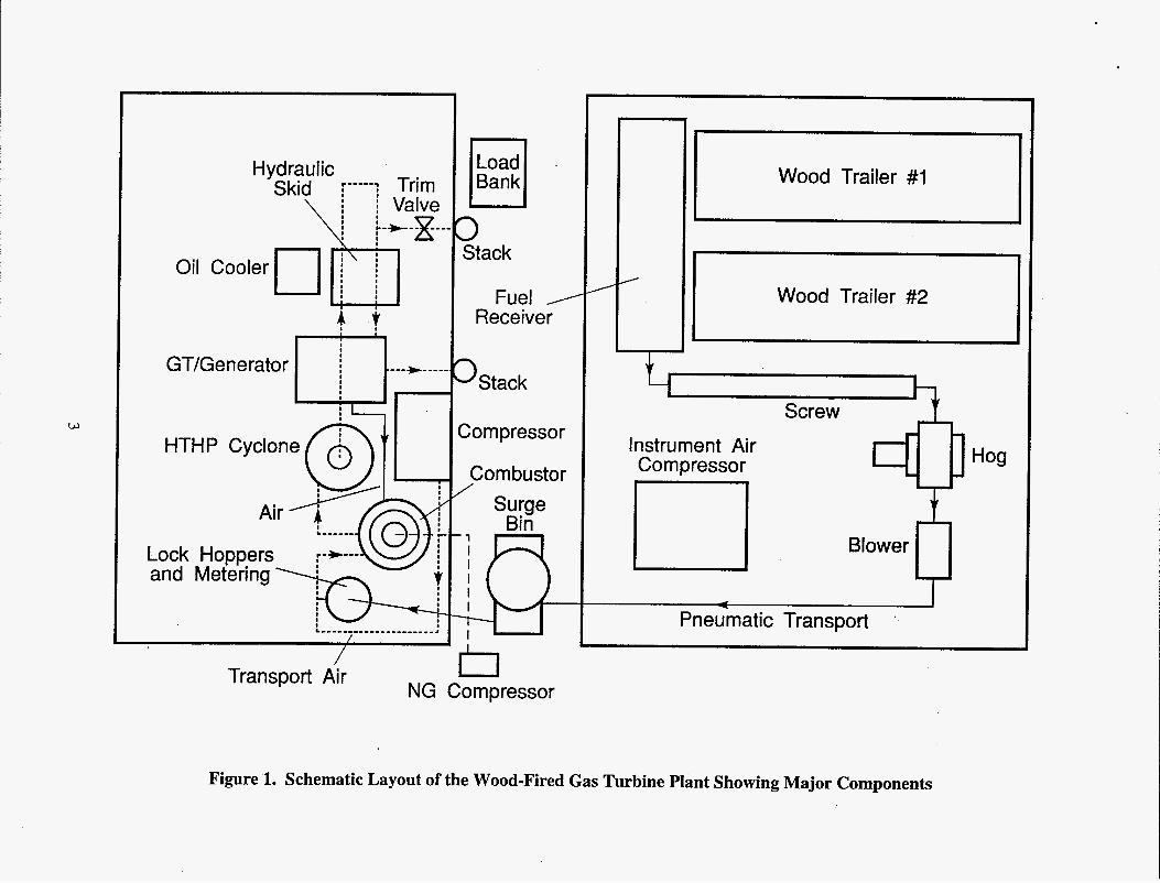
A 60-ft x 50-ft building has been completed at the WRT's Advanced Technology Center. The high bay area of the building is being used to house the demonstration plant. A 40-ft x 50-ft shed has also been erected on a concrete pad adjacent to the building, to accommodate the fuel receiving and preparation equipment for the project. A schematic layout of the plant is shown in Figure 1.
The fuel preparation system consists of a fuel receiver hopper designed to receive wood shavings from two self-unloading trailers. A 12-in. dia. screw is used to transport the fuel to a hammermill (Hog). A blower then transports the fuel to a 36-in. dia. cyclone located on top of a surge bin. These facilities are located in the 40-ft x 50-ft shed. Fuel is then transported into the project building by means of a lift screw to the top of a lockhopper arrangement.
Fuel pressurization is achieved through the use of lockhoppers employing pneumatically actuated eccentric ball valves. Fuel is metered using a screw coupled to a variable-speed drive motor. Fuel is then pneumatically injected into the combustor. Transport air is provided by an Ingersol Rand compressor.
2
Oil Cooler I
I
HTHP Cyclone
Lock Hoppers and Metering
I
I
I
q Bank
w
/ Transport Air r l
NG Compressor
1 tack
Fuel / Receiver
I Stack
Dmpressor
=ombustor Surge
Q
I
Wood Trailer #1
I I
1 Wood Trailer #2
1 Screw Instrument Air Compressor
I Pneumatic Transport .
Figure 1. Schematic Layout of the Wood-Fired Gas Turbine Plant Showing Major Components
The combustor is basically a suspension burner, fabricated by McConnell Industries. The unit has full-fire dual-fuel and mixed-fuel capability, in that the plant can operate at full load with natural gas, wood, or any combination. A natural gas burner is attached to the top of the combustion chamber, whereas wood is fired tangentially. Combustion air from the compressor enters the combustor through the natural gas burner, through three tueyers, and as quench air. All air flows can be individually controlled and monitored.
Pressurized hot gases are ducted to a refractory-lined, high-temperature, high-pressure cyclone fabricated by Ducon Environmental. The IO-in. dia. hot gas ducting from the combustor to the cyclone is constructed from 24411. dia. carbon steel pipe. The cyclone and the ducting are lined with 6-in. thick refractory. Ash collected by the cyclone is removed by a cooled hollow flight screw through a pair of 4-in. ball valves.
The hot gas ducting from the cyclone to the gas turbine is similar in design to that being used at the Tidd pressurized fluidized bed combustor (PFBC). The 10-in. i.d. duct sections were constructed from 24-in. dia. carbon steel pipe and lined with refractory and a type 304 ss liner.
The plant is designed around a Garrett IE83-800 engine. The engine was modified by Turbo Tech at their facilities before it was sent to WRI. Accelerometers, a new thrust bearing with integral thermocouples and an external monopole were installed. Based on an on-site dimensional review of the turbine, the variable frequency motor originally proposed as a starter for the system was replaced with a hydraulic drive. By using the Bendix assembly typically supplied with an air starter on the Garrett E 8 3 1-800, it appeared that a hydraulic starter motor would be much easier to install in the limited space available.
The engine also required a specially designed manifold for interfacing with the hot gas ducting. An approximately 52-in. long piece of concentric pipe is used to deliver the hot pressurized gas to the expander and to direct the compressed air from the compressor toward the combustor. Hot gas travels to the expander through the inner pipe constructed from Hastelloy X, whereas compressor discharge travels through the refractory lined type 304 ss annulus. Process control required the addition of an orifice to the hot gas stream to isolate the control side of the tribune from the large mass flow contained in the hot gas cleanup, hot gas ducting and combustor. The need for this restriction and a trim valve to gain a better control on turbine operations were identified in consultations with the engineers from Allied Signal Engines, the turbine manufacturer who now owns Garrett.
4
The trim valve is a high-pressure, high-temperature butterfly valve with cooled ceramic bearings. Cooling air is taken from the compressor discharge. The valve is sized to allow engine speed control and overspeed protection. Actuation of the valve is by servo hydraulic, and in case of an emergency, the valve can open from fully closed to fully open position in about 0.1 s.
Startup and warmup are achieved by firing natural gas. A gas compressor is used to pressurize pipeline gas. A natural gas train then delivers the fuel to the burner at the desired pressure.
The motor control center (MCC) is located in a building outside the main plant building, and the control room is isolated from the high bay area. All control and monitoring functions are through GE process logic controllers interfaced with a pair of desktop computers. Two additional desktop computers serve as data loggers. The two computers log data at two different speeds, one at 0.2 Hz and the other at 2 Hz. In case of a transient, the latter is also configured to log data at higher rates with the push of a key.
Plant Operations
The plant was still being assembled when some of the shakedown activities began. For example, wood preparation equipment was still not at the site, the stack was still not installed and the trim valve was stiIl at SDI when the engine was motored for the first time on July 26, 1995. Cold flow testing and leak checking were completed. A major leak was discovered at the cyclone main body flange. A gasket at the main flange was found to be the problem. A replacement gasket was installed on August 15, 1995. Meanwhile, the hydraulic pump appeared not to be delivering enough pressure to operate the engine at desired speeds. Pump repairs were completed on August 8, 1995, and cold flow testing resumed.
The first fire in the unit was achieved on August 28, 1995, at 15:37. Control loop tuning, refractory drying and curing, and operator training proceeded concurrently, while the plant was operated on a two-shifts-a-day schedule. Self-sustained operation of the plant was successfully achieved on October 18, 1995.
The wood preparation and delivery system was completed and tested concurrently with other shakedown activities. The first load of wood was run through the system on September 20, 1995. Particle size distribution achieved by the system is given in Table 1.
5
Screen Size 1 /4 118 1/16
40 mesh 50 mesh -50 mesh
Table 1. Particle Size Distribution Achieved by the Wood-Fired Gas Turbine System
As Re ceived Material Suree Bi ‘n Material
Retained (g) % Retained (g) %
43.80 11.2 0.00 0.0
100.30 25.8 0.10 0.0
151.70 39.0 43.80 7.6 86.60 22.2 455.90 79.5 3.50 0.9 35.00 6.1
3.50 0.9 38.60 6.7
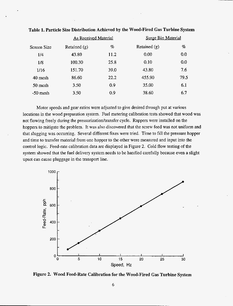
Motor speeds and gear ratios were adjusted to give desired through put at various locations in the wood preparation system. Fuel metering calibration tests showed that wood was not flowing freely during the pressurizationltransfer cycle. Rappers were installed on the hoppers to mitigate the problem. It was also discovered that the screw feed was not uniform and that slugging was occurring. Several different fixes were tried. Time to fill the pressure hopper and time to transfer material from one hopper to the other were measured and input into the control logic. Feed-rate calibration data are displayed in Figure 2. Cold flow testing of the system showed that the fuel delivery system needs to be handled carefully because even a slight upset can cause pluggage in the transport line.
loo0 r
I I I I I J 0 5 10 15 20 25 30
Speed, Hz
Figure 2. Wood Feed-Rate Calibration for the Wood-Fired Gas Turbine System
6
The first electrical load was applied to the engine on November 9, 1995, while the engine was operating at 39,000 rpm. Sustained operation at 100 kW applied load was achieved on November 14, 1995. An attempt to apply a 150-kW load caused a master fuel trip and excessive combustor outlet temperature. A decision was made to operate the plant below its design capacity and only to work at load levels at or below 100 kW.
The first wood-fired operation was achieved on November 21, 1995, at 13:17. The lockhoppers and metering functions were controlled manually. Several wood firing rates were tried. The highest rate achieved was about 300 pph. Combustor exit temperature at the time was about 1550 O F . The engine was operating at 39,300 rpm with 100 kW electrical load. On November 21, 1995, approximately 540 Ibs of wood was fired over a seven-hour period. Cumulative on-wood time logged was about 2 hours and 12 minutes. Experience showed that several modifications to the wood system hardware, control logic, and procedures were required for reliable operation. These included changes in transfer times, a pressure equalization line between the hoppers, and gear changes for faster fill times. For later testing, these modifications were implemented.
On November 29, 1995, it was discovered that the engine would not rotate. A review of the data from the previous run and discussions with Allied Signal Engines indicated that this was probably caused by coking of the oil at the bearings due to heat soakback after the November 22, 1995 shutdown. The power section of the engine was removed and sent to Allied Signal Engines facilities in Phoenix, Arizona, for inspection and repairs. Inspection confirmed the speculated cause. Once the rear bearing was removed, the spool rotated freely on the front journal and thrust bearing. Rear bearing parts were replaced and the power section was reassembled. An acceptance was performed on the power section. Performance of the unit was found to be satisfactory.
The repaired assembly was reinstalled at the plant on December 1 1 , 1995, and shakedown testing continued. Shutdown procedures were modified to prevent similar incidents of heat soakback.
Control systems for automated wood firing were implemented and tested during the period leading to Christmas break. The plant underwent several startups and unexpected shutdowns while automated wood firings were attempted. Several issues were identified and addressed. The ash removal system was modified, the fuel feed system redesigned, and timings for fuel transfer cycles were modified. The pneumatic fuel transport air system needed to be modified to facilitate cleaning in case of pluggage.
7

An inspection of the plant on December 19, 1995, showed that unexpected shutdowns while the plant operated on wood caused blowback of ash into the compressor section of the engine. All accessible areas were cleaned of soot and ash deposits. All control and monitoring equipment in the compressed air ducting was inspected for similar deposits, and if found dirty, cleaned. The trim valve was removed and inspected. Bearings in the trim valve were found to be seized and carried sooty deposits, and the adaptor spool for the trim valve was found to show some refractory damage. The spool was removed and sent for repairs and modifications.
The hot section of the plant was reassembled and ready for operations on January 5, 1996. Wood feed system modifications were ready on January 11, 1996. The plant was operated on natural gas between January 5 and January 11,1996. On January 12,1996, it was discovered that the trim valve bearings had seized again. The bearings were cleaned and the valve reassembled. A knock-out pot was installed in the cooling air line to prevent arrival of foreign material at the trim valve bearings.
The plant was back online on January 17, 1996. The feed system was put into operation on January 20, 1996, while automated controls and logic were tuned and tested. Several unexpected shutdowns were experienced while the logic was being reprogrammed. Each shutdown also caused the fuel feed line to plug, as a sudden pressure change caused an uncontrolled amount of wood to be transported from the pressure hopper through the feed screw into the transport line. On January 23, 1996, a fix was designed as a rubber dam installed at the discharge end of the feed screw to minimize transport line pluggage, and wood feed system testing and reprogramming continued. Approximately 200 minutes of sustained operations on partial wood feed were achieved at firing rates between 100 to 250 pph (20 to 40 % of thermal input). Approximately 580 lbs of wood was fired during this period.
On January 24, 1996 several unsuccessful attempts were made to feed wood. All led to a plant trip caused either by an overtemperature condition at the combustor exit or by fuel surges. Sustained wood firing was achieved on January 25, 1996, for about 390 minutes. During this period, all control functions were placed in auto mode. Wood firing rates were limited by the programed controls and hence could not.exceed 60 % of total thermal input. Total amount of wood fired in the system during this period was about 1450 lbs. The plant was shut down for an inspection.
Plant intemals were inspected on January 29, 1996. The combustor contained some refractory fragments and agglomorated char. The ash withdrawal system contained some water and char. Engine exhaust and compressor intake were found to be relatively clean and appeared to be
8
the same as on natural gas operations. The trim valve had a very minor deposit of ash at the leading edge of the butterfly.
Plant modifications in the wood feed system were completed on January 30 and 3 1, 1996. These included installation of a pressure equalization line between the pressure hopper and the metering bin and installation of a pneumatic actuator on the transport air control valve.
On February 1 and 2, the plant was operated on wood on an on and off basis at rates up to 40% of thermal input. About 750 lbs of wood was fired over this period.
The plant was restarted on February 5, 1996. Wood feed was initiated on the morning of February 6, 1996, and continued for about 500 minutes. The highest wood firing rate achieved was 85% of thermal input, approximately 500 pph. Total amount of wood fired was about 2450 Ibs. Wood feed was again initiated on February 7, 8, and 9 at firing rates up to 550 pph. Nearly 5150 lbs of wood were fired during this week’s operations, and the plant was shut down for inspection.
The plant inspection did not show any deleterious effect of wood firing on any visible components of the engine. Similarly, no visible signs of distress were detected in the combustor, burner, and trim valve assembly.
On February 12, 1996, additional rappers were installed on the metering bin to promote uniform wood flow in the bin.
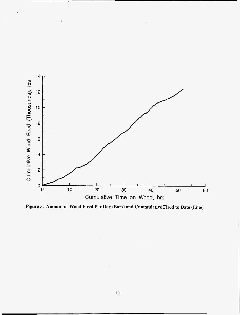
On several occasions from February 13 through March 6, 1996, the plant was operated on wood feed. Several firing rates under different operating conditions were tried. Through March 6, 1996, the plant had consumed about 13,000 Ibs of wood (see Figures 3 and 4)
During the February-March testing, several unexpected shutdowns were experienced. Detailed analyses of some of the events were undertaken with Allied Signal Engines’s assistance and guidance. Some events were related to surging and others to possible deterioration of compressor performance. Limited boroscope inspection of the compressor did not reveal any obvious cause of performance degradation, however, it is speculated that interstage seals may have leaked during some of the tests. Procedural and hardware modifications were tried during the month of March 1996, to alleviate the compressor surging.
9
14
12
10
20 30 40 50 60 0
0 10 Cumulative Time on Wood, hrs
Figure 3. Amount of Wood Fired Per Day (Bars) and Cummulative Fired to Date (Line)
10

0 0 0 m T-
0 0 0 0,
0 0 0 CD
0 0 0 c3 0
T- \ c3
0 0 m cu
0 0 0 cu
0
T-
11

.
DISCLAIMER
Mention of specific brand names or models of equipment is for information only and does not imply endorsement of any particular brand.
12

M97005487 I1111ll11 Ill 11111 11111 11111 lllll11111111ll11111 Ill1 1111
Report Number (14) b@%f!fldS\aq -- s7 90
'ubi. Date (11)
Sponsor Code (1 8) JC Category (19)
DOE