development and modelling of compact dual membrane
TRANSCRIPT

Development and modelling of compact dual
membrane contactor for gas treatment
by
©
Jing Jing Cai
A thesis submitted to the
School of Graduate Studies
in partial fulfilment of the
requirements for the degree of
Doctor of Philosophy
Faculty of Engineering and Applied Science
Memorial University of Newfoundland
July 2016
St. John's Newfoundland
I
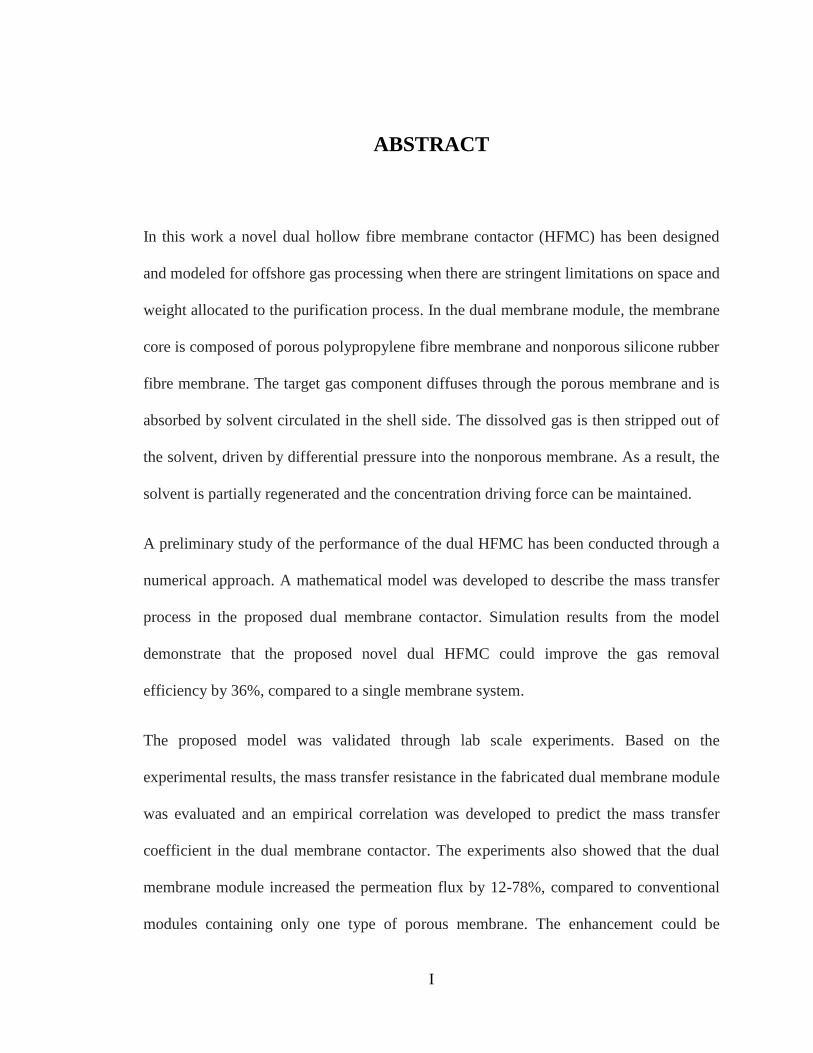
ABSTRACT
In this work a novel dual hollow fibre membrane contactor (HFMC) has been designed
and modeled for offshore gas processing when there are stringent limitations on space and
weight allocated to the purification process. In the dual membrane module, the membrane
core is composed of porous polypropylene fibre membrane and nonporous silicone rubber
fibre membrane. The target gas component diffuses through the porous membrane and is
absorbed by solvent circulated in the shell side. The dissolved gas is then stripped out of
the solvent, driven by differential pressure into the nonporous membrane. As a result, the
solvent is partially regenerated and the concentration driving force can be maintained.
A preliminary study of the performance of the dual HFMC has been conducted through a
numerical approach. A mathematical model was developed to describe the mass transfer
process in the proposed dual membrane contactor. Simulation results from the model
demonstrate that the proposed novel dual HFMC could improve the gas removal
efficiency by 36%, compared to a single membrane system.
The proposed model was validated through lab scale experiments. Based on the
experimental results, the mass transfer resistance in the fabricated dual membrane module
was evaluated and an empirical correlation was developed to predict the mass transfer
coefficient in the dual membrane contactor. The experiments also showed that the dual
membrane module increased the permeation flux by 12-78%, compared to conventional
modules containing only one type of porous membrane. The enhancement could be
II
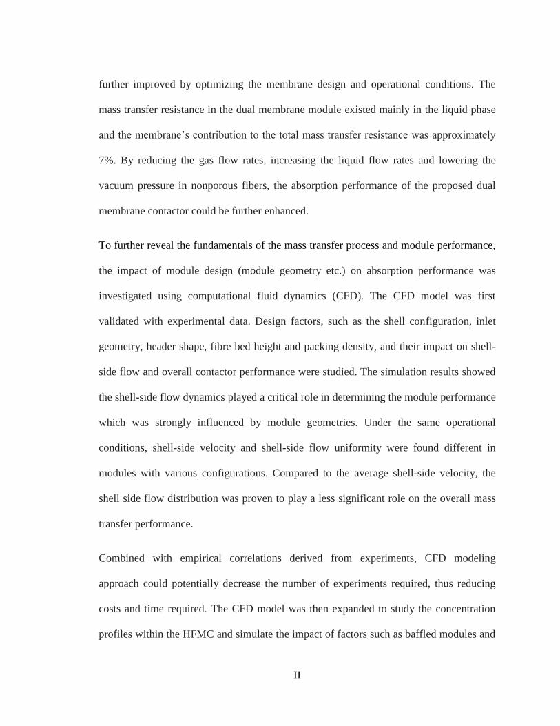
further improved by optimizing the membrane design and operational conditions. The
mass transfer resistance in the dual membrane module existed mainly in the liquid phase
and the membrane’s contribution to the total mass transfer resistance was approximately
7%. By reducing the gas flow rates, increasing the liquid flow rates and lowering the
vacuum pressure in nonporous fibers, the absorption performance of the proposed dual
membrane contactor could be further enhanced.
To further reveal the fundamentals of the mass transfer process and module performance,
the impact of module design (module geometry etc.) on absorption performance was
investigated using computational fluid dynamics (CFD). The CFD model was first
validated with experimental data. Design factors, such as the shell configuration, inlet
geometry, header shape, fibre bed height and packing density, and their impact on shell-
side flow and overall contactor performance were studied. The simulation results showed
the shell-side flow dynamics played a critical role in determining the module performance
which was strongly influenced by module geometries. Under the same operational
conditions, shell-side velocity and shell-side flow uniformity were found different in
modules with various configurations. Compared to the average shell-side velocity, the
shell side flow distribution was proven to play a less significant role on the overall mass
transfer performance.
Combined with empirical correlations derived from experiments, CFD modeling
approach could potentially decrease the number of experiments required, thus reducing
costs and time required. The CFD model was then expanded to study the concentration
profiles within the HFMC and simulate the impact of factors such as baffled modules and

III
modules containing unevenly distributed fibre bundle. The research demonstrated that the
CFD simulation could be used as an effective design tool in the development and
optimization of cross flow membrane module.
Compared to the conventional absorption column, the lab scale dual membrane contactor
designed and fabricated in this study could reduce the footprint by 80% and solvent
consumption by 70%. This result was obtained by comparing the experimental results
from a lab scale packed column to the modeled results of dual membrane module
containing the equivalent amount of interfacial area. This difference could be further
enhanced by increasing the fiber packing density in the membrane core of dual membrane
module. The compatibility, capability in reducing size and solvent consumption and ease
in operation makes the dual membrane contactor ideal candidate for offshore gas
processing where space has stringent specifications.
Keywords: Hollow fibre membrane contactor, module design, cross-flow, shell flow
dynamics, computational fluid dynamics (CFD) simulation

IV
ACKNOWLEDGEMENT
The long journey towards pursuing the Ph. D degree finally comes to a successful end. It
is a journey full of challenges, innovation, excitements, and occasional frustrations.
Fortunately, I was never alone traveling through this journey. There are a number of
people behind this piece of work who deserve to be both acknowledged and thanked here.
It is them who made me more than who I am and I am so grateful to have them by my
side.
First and foremost, I would like to thank two of my supervisors, Dr. Kelly Hawboldt and
Dr. Majid Abdi, for their guidance, unrelenting support and friendship throughout this
process. I am privileged to have the opportunity to work with them. Kelly, thank you for
trusting me and allowing me to explore my own ideas while staying closely to steer me
back to the right track when I am confused or lost; thank you for going beyond your
duties to fire fight my worries, concerns, and anxieties and instilling confidence in myself
and my work. I will never forget how your encouragement and humor brightened my
days in times of stress. Majid, thank you for your tireless support, timely encouragement
and valuable advice in the past few years. Your passion for research, diligent work ethic
and frequent insight and patience are invaluable to me. I also would like to thank Dr.
Faisal Khan, who is the member of my Ph.D committee. Thank you for your feedback,
direction, and assistance when I needed it.
V
I would like to acknowledge the academic, financial and technical support from the
Faculty of Engineering and Applied Science. In particular, thanks to Dr. Lesley James
and Dr. Yan Zhang for their help and inspiring discussion on my study and research
throughout my Ph.D. program; thanks to Frank Pippy, Caroline Koenig, William Bidgood,
David Snook, Kelly Leshane for providing constant technical support to my experimental
work; thanks to Dr. Leonard Lye for your valuable experience and insightful guidance on
academic writing; and thanks to Moya Crocker, Colleen Mahoney, Nicole Parisi for your
daily assistance.
Financial support was gratefully provided by the Faculty of Engineering and Applied
Science, Memorial University (MUN), National Research Council of Canada (NSERC),
Development Corporation of Newfoundland and Labrador (RDC).
I have been so lucky to make many good friends over my years living in St. John's and
their friendship made my life more enjoyable and unforgettable. Particularly, I would like
to thank Mr. Rick Siu, Ms. Janice Siu and Mr. Simon Tam, for all their continuous
prayers and supports. A sincere thanks to my gangs, Xiaonan Wu, Lei Wang and Nan
Zhang for sharing laughs and tears with me, and for simply listening to me.
Family gave me a great deal of support throughout my degree and my life in St. John’s. I
would like to extend my inexpressible gratitude to my parents and parents in-law for their
unconditional love, comfort and advice. Most of all, I would like to offer my deepest
thanks to my husband, Liang Jing. Thank you for believing in me and holding my hands

VI
through all the ups and downs. Your love, tolerance and patience turned this long journey
into a pleasure.
VII
TABLE OF CONTENTS
ABSTRACT ......................................................................................................................... I
ACKNOWLEDGEMENT ................................................................................................ IV
TABLE OF CONTENTS ................................................................................................. VII
TABLE OF FIGURES………………………………………………………………..…XII
TABLE OF TABLES ................................................................................................... XVII
LIST OF SYMBOLES .................................................................................................... XIX
CHAPTER 1 ........................................................................................................................ 1
INTRODUCTION ............................................................................................................... 1
1.1 Motivation .................................................................................................................. 4
1.2 Objectives ................................................................................................................... 5
1.3 Dissertation Structure ................................................................................................. 7
References ........................................................................................................................ 9
CHAPTER 2 ...................................................................................................................... 12
LITERATURE REVIEW .................................................................................................. 12
2.1 Overview of Gas processing..................................................................................... 12
2.2 Membrane technologies used for gas processing ..................................................... 15
2.2.1 Membrane separation......................................................................................... 15
2.2.2 Gas absorption using membrane contactors ...................................................... 18
2.2.3 Mass transfer in membrane contactors .............................................................. 20
2.2.4 Modeling of mass transfer in membrane contactors .......................................... 24
2.3 Designing membrane contactors .............................................................................. 25
2.3.1 Selection of absorption solvent .......................................................................... 27
VIII
2.3.2 Selection of membrane material ........................................................................ 29
2.3.3 Operation modes of membrane contactors ........................................................ 31
References ...................................................................................................................... 34
CHAPTER 3 ...................................................................................................................... 40
DEVELOPMENT OF NOVEL DUAL MEMBRANE CONTACTOR FOR GAS
ABSORPTION .................................................................................................................. 40
3.1 Background .............................................................................................................. 41
3.2 Dual membrane contactors ...................................................................................... 44
3.3 Model Development ................................................................................................ 46
3.3.1 Overall mass transfer in liquid phase ................................................................ 47
3.3.2 Gas phase mass balance within porous membrane ............................................ 50
3.3.3 Gas phase mass balance with nonporous membranes ....................................... 51
3.4 Results and discussion .............................................................................................. 52
3.4.1 Model validation ................................................................................................ 52
3.4.2 The performance of dual membrane contactor .................................................. 56
3.4.3 The effect of packing fraction of membranes .................................................... 65
3.5 Conclusion ................................................................................................................ 67
References ...................................................................................................................... 68
Chapter 4 ............................................................................................................................ 72
EXPERIMENTAL STUDY OF GAS ABSORPTION USING DUAL MEMBRANE
CONTACTOR ................................................................................................................... 72
4.1 Background .............................................................................................................. 73
4.2 Experiments .............................................................................................................. 76
4.2.1 Fabrication and assembly of lab scale dual membrane contactor...................... 76
4.2.2 Experimental set-up ........................................................................................... 78
IX
4.3 Mathematical model for dual membrane module .................................................... 81
4.4 Results ...................................................................................................................... 82
4.4.1 Correlation for mass transfer coefficient in shell side ....................................... 82
4.4.2 The effect of liquid flow rate on mass transfer .................................................. 93
4.4.3 The effect of gas flow rate ................................................................................. 98
4.4.4 The effect of solute concentration ................................................................... 100
4.4.5 The effect of vacuum pressure on the permeate side ....................................... 104
4.4.6 The effect of area ratio of porous and nonporous membrane .......................... 106
4.4 Conclusion .............................................................................................................. 108
Reference ...................................................................................................................... 111
Chapter 5 .......................................................................................................................... 115
ANALYSIS OF THE EFFECT OF MOUDLE DESIGN ON GAS ABSORPTION IN
CROSS-FLOW HOLLOW FIBER MEMBRANE CONTACTORS VIA
COMPUTATIONAL FLUID DYNAMICS (CFD) ANALYSIS .................................... 115
5.1 Background ............................................................................................................ 117
5.2 Theory .................................................................................................................... 120
5.2.1 Momentum Equation and Porous media approach .......................................... 120
5.2.2 Continuity Equation and Gas Transport .......................................................... 122
5.3 Methodology .......................................................................................................... 124
5.3.1 Experimental validations ................................................................................. 124
5.3.2 CFD modeling approach .................................................................................. 128
5.4 Results and Discussions ......................................................................................... 129
5.4.1 Model validation .............................................................................................. 129
5.4.2 Impact of module design factors...................................................................... 131
5.4.3 The effect of shell geometry ............................................................................ 132
X
5.4.4 The effect of Inlet geometry ............................................................................ 136
5.4.5 The effect of membrane bed height ................................................................. 142
5.4.6 The effect of packing density .......................................................................... 145
5.5 Conclusions ............................................................................................................ 148
Reference ...................................................................................................................... 150
Chapter 6 .......................................................................................................................... 154
NUMERICAL STUDY OF GAS ABSORPTION-DESORPTION IN DUAL
MEMBRANE CONTACTORS USING CFD MODELING .......................................... 154
6.1 Background ............................................................................................................ 155
6.2 Materials and methods ........................................................................................... 158
6.3 Mass transfer model ............................................................................................... 160
6.3.1 CFD model for shell side flow and mass transfer............................................ 160
6.3.2 CFD model for fibre side flow and mass transfer ........................................... 165
6.3.3 Solution methodologies and computer algorithm ............................................ 166
6.4 Experimental validation ......................................................................................... 169
6.5 Results .................................................................................................................... 172
6.5.1 Experimental validation of CFD model ........................................................... 172
6.5.2 Performance comparison of dual membrane contactor and absorption
column...……………………………………………………………………………176
6.5.3 CFD application to design ............................................................................... 180
6.5.4 The effect of fibre arrangement on mass transfer ............................................ 183
6.6 Conclusions ............................................................................................................ 185
Reference ...................................................................................................................... 187
Chapter 7 .......................................................................................................................... 190
CONCLUSIONS AND FUTURE WORKS .................................................................... 190
7.1 Summary ................................................................................................................ 190

XI
7.2 Research Contributions .......................................................................................... 191
7.3 Publications ............................................................................................................ 197
7.4 Recommendations for Future work ........................................................................ 198
Reference ...................................................................................................................... 200

XII
TABLE OF FIGURES
Figure 1.1: Comparison of footprint and size between membrane unit and typical
absorption column………...................................................................................... ……….4
Figure 2.1 : Typical natural gas absorber-stripper treatment process using amine
absorbents to remove carbon dioxide (Baker et al., 2008) ................................................. 14
Figure 2.2: Schematic drawing of membrane separation process with different driving
force is present (Strathmann, 2011) ................................................................................... 16
Figure 2.3: Technology screening for CO2 removal (Isa et al., 2009) ............................... 19
Figure 2.4: Mass transfer regions and dominant resistances in a membrane contactor
(Dindore 2005). .................................................................................................................. 21
Figure 2.5: Nonwetted membrane contactor and wetted membrane contactor (Dindore, et
al., 2005) ............................................................................................................................ 22
Figure 2.6 Surface areas to volume ratios of various membrane module configurations .. 26
Figure 2.7: Cross flow and Parallel flow mode membrane contactors .............................. 32
Figure 3.1 : (a) Module I - Cross flow Dual HFMC; (b): Module II - Cross flow dual
HFMC with baffles ............................................................................................................ 45
Figure 3.2 : Cross section and modeling parameters in cross flow membrane contactor (a)
simplified module of cross flow dual HFMC; (b) side view of differential segment; and (c)
front view of differential segment ...................................................................................... 48
Figure 3.3 : Parity plot of model results and the experimental data (Dindore et al., 2005)
for CO2 concentration at gas outlet (QG=2.21×10⁻⁴
m3/s) .................................................. 55
XIII
Figure 3.4: Parity plot of model results and the experimental data (Dindore et al., 2005)
for CO2 concentration at liquid outlet (QG=2.21×10⁻⁴
m3/s) .............................................. 56
Figure 3.5: Fibre side concentration profile of CO2 in dual membrane module for constant
inlet gas flow rate of 2.66×10⁻⁵
m3/s and liquid flow rate of 7.8×10
-5 m
3/s....................... 59
Figure 3.6: Absorption of 39.33 mol/m3 CO2 absorption under different liquid velocity for
constant inlet gas flow rate of 2.66×10⁻⁵
m3/s .................................................................... 60
Figure 3.7: Cascading of two single membrane modules .................................................. 61
Figure 3.8: CO2 rovery under different liquid flow rates in different modules for constant
inlet gas flow rate of 2.66×10⁻⁵
m3/s .................................................................................. 63
Figure 3.9: CO2 recovery rate under different gas flow rates for constant inlet liquid flow
rate of 1×10⁻⁵
m3/s .............................................................................................................. 65
Figure 4.1(a): Schematic drawing of membrane core and arrangement of dual hollow
fibre membranes in lab scale module; (b) Schematic drawing of dual membrane contactor
............................................................................................................................................ 77
Figure 4.2: Experimental set-up for CO2 absorption in dual membrane contactor ........... 79
Figure 4.3: Comparison of mass transfer correlations developed for different membrane
contactors ........................................................................................................................... 86
Figure 4.4 Mass transfer regions and resistance-in-series in non-wetted dual membrane
contactor ............................................................................................................................. 87
Figure 4.5: Wilson’s plot for the proposed module ........................................................... 89
Figure 4.6 Parity plots of Sherwood number obtained for different operation conditions 91
Figure 4.7 Mass transfer coefficient of dual hollow fibre membrane contactor for both
solvents tested .................................................................................................................... 93

XIV
Figure 4.8 : CO2 (5%) absorption in dual membrane module with sweeping gas degassing
............................................................................................................................................ 95
Figure 4.9 : Effect of liquid flow rate on absorption flux .................................................. 97
Figure 4.10: Effect of liquid flow rate on absorption flux using propylene carbonate as
solvent ................................................................................................................................ 98
Figure 4.11: Effect of gas flow rate on absorption flux using water as solvent.............. 100
Figure 4.12: The effect of solute concentration on absorption performance ................... 102
Figure 4.13 : Effect of simultaneous solvent regeneration on absorption performance . 104
Figure 4.14: The effect of permeate side pressure to overall absorption performance .... 105
Figure 4.15: The effect of porous membrane area on absorption performance and the
enhancement resulted from degassing ............................................................................. 107
Figure 5.1: (a) Schematic drawing of cross flow module; (b) bottom view of cross flow
module; (c) front view of cross flow module ........................................................................ 125
Figure 5.2: Schematic drawing of the experimental setup for CO2 absorption using cross
flow HFMC ................................................................................................................................ 127
Figure 5.3: CO2 absorption in lab scale module .................................................................... 129
Figure 5.4: Middle-plane cut view porous zone to show the simulated concentration
profile and magnitude (a) front view; (b) top view ............................................................... 130
Figure 5.5: Schematic drawing of rectangular module and cylindrical module ............... 133
Figure 5.6: Effect of shell geometry on membrane module performance ...................... 134
Figure 5.7: Effect of shell geometry on shell-side flow ................................................... 136
Figure 5.8: The effect of inlet dimension on shell-side flow velocity and mixing
(CO2Gin=44.64 mol/m3, QG=2.67×10
-5m
3/s) .................................................................... 138
XV
Figure 5.9: The effect of inlet dimension on shell-side flow velocity distribution and
absorption flux (CO2Gin=44.64 mol/m3, QG=2.67×10
-5m
3/s) ........................................... 139
Figure 5.10: Schematic drawing of module with different designs of inlet geometries: (a)
Rectangular module without header; (b) Module with short cone shaped header; (c)
Module with long cone shaped header ............................................................................. 140
Figure 5.11: The effect of header design on absorption flux (CO2Gin=44.64 mol/m3,
QG=2.67×10⁻⁵
m3/s) ........................................................................................................... 141
Figure 5.12: The effect of header design on shell-side flow (CO2Gin=44.64 mol/m3,
QG=2.67×10⁻⁵
m3/s) ........................................................................................................... 142
Figure 5.13: Effect of membrane bed height on shell-side flow dynamics (CO2Gin=44.64
mol/m3, QG=2.67×10
-5m
3/s, QL=0.85×10
-5m
3/s) ............................................................. 144
Figure 5.14: Effect of membrane bed height on absorption performance (CO2Gin=44.64
mol/m3, QG=2.67×10
-5m
3/s, QL=0.85×10
-5m
3/s) ............................................................. 145
Figure 5.15: Effect of packing density on shell-side flow dynamics (CO2Gin=44.64 mol/m3,
QG=2.67×10⁻⁵
m3/s, QL=0.85×10
-5m
3/s) ........................................................................... 146
Figure 5.16: Effect of packing density on absorption performance (CO2Gin=44.64 mol/m3,
QG=2.67×10⁻⁵
m3/s, QL=0.85×10
-5m
3/s) ........................................................................... 148
Figure 6.1: Schematic drawing of lab scale module ........................................................ 159
Figure 6.2: A Cartesian control volume in the porous media for derivation of the species
conservation equation. ..................................................................................................... 162
Figure 6.3 : Schematic of fibre bundles in the shell side of cross flow dual membrane
module .............................................................................................................................. 165

XVI
Figure 6.4 : Schematic drawing of computational domain for fibre side in the cross flow
dual membrane contactor ................................................................................................. 165
Figure 6.5 : Flow chart of computer algorithm. ............................................................. 168
Figure 6. 6 : Experimental set-up for CO2 absorption in dual membrane contactor........ 171
Figure 6.7: A comparison of modelled results with experimental measurement
(CO2in%=5%, Qg=5.6×10⁻⁶
m3/s) ..................................................................................... 173
Figure 6.8: Comparison of CO2 at gas outlet between experiment and CFD model
(CO2in%=5%, QL was varied from 10-6
m3/s to 8.33×10
-6m
3/s)........................................ 174
Figure 6.9: Comparison of CO2 at liquid outlet between experiment and CFD model.
CO2in%=5%, QL was varied from 10-6
m3/s to 8.33×10
-6m
3/s) ......................................... 175
Figure 6.10 : CO2 concentration distribution (mol/m3) in porous media (fibre bundles)
(CO2in%=30%, QL=6.6 ×10⁻⁶
m3/s, QG=5.6×10
-6m
3/s) ..................................................... 176
Figure 6.11: Experimental set-up of lab scale packed column for gas absorption (CE-400
Gas absorption column, manufactured by G.U.N.T, Germany) ...................................... 178
Figure 6.12: Performance of packed column compared to dual membrane contactor for
CO2 absorption ................................................................................................................. 179
Figure 6.13: The volume of dual membrane contactor with various packing density
compared to that of packed column ................................................................................. 180
Figure 6.14: Schematic of baffled modules (a) module with 1 baffle; (b) module with 2
baffles; (c) module with 3 baffles .................................................................................... 181
Figure 6.15: Effect of baffle numbers on absorption flux (CO2in%=30%, QG=5.6×10⁻⁶
m3/s)
.......................................................................................................................................... 182
XVII
Figure 6. 16: Effect of solute concentration on the performance of baffled module for CO2
absorption (QG=5.6×10⁻⁶
m3/s, QL=5.6×10
-6m
3/s) ............................................................ 183
Figure 6.17: Effect of non-uniform fibre distribution on CO2 absorption flux in cross flow
module (CO2% in feed gas=30%, QG=5.6×10⁻⁶
m3/s) ...................................................... 185
XVIII
TABLE OF TABLES
Table 2.1: Membrane-solvent compatibility (Dindore et al., 2005)…………………..….30
Table 3.1: Specifications of module and their references .................................................. 58
Table 3.2: Comparison of CO2 concentration change in two circulating module and dual
membrane module .............................................................................................................. 62
Table 4.1: Specification of lab scale dual membrane module ........................................... 78
Table 4.2: Experimental conditions for test conducted in the research presented in this
chapter ................................................................................................................................ 80
Table 4.3: Experimentally data and calculated Reynolds number and Sherwood number 84
Table 4.4: The parameters used in the model .................................................................... 92
Table 5.1: Specifications of cross flow module and membrane properties ..................... 126
Table 5.2: Parameter used in membrane simulation model ............................................. 128
Table 5.3: Specifications of rectangular module and cylindrical module........................ 133
Table 6.1: Specifications of cross flow module and membrane properties ..................... 159
Table 6.2: Physical and transport properties of the hollow fibre membrane cores .......... 169
Table 6.3: Module specifications of cross flow dual membrane module ........................ 170
Table 6.4: Specifications of CE-400 absorption column and operation conditions......... 177

XIX
LIST OF SYMBOLES
A area m2
Am membrane surface area per unit total volume m-1
C concentration mol/m3
C1 permeability coefficient
C2 inertial loss coefficient
CG concentration in gas phase mole/m3
CL concentration in liquid phase mole/m3
CSNP concentration in the surface of nonporous membrane mole/m3
D diffusion coefficient m2/s
d diameter m
d0 Membrane fiber outside diameter m
Deff effective diffusivity m2/s
dh hydraulic diameter m
Dw CO2 diffusion coefficient in water m2/s
g gravity force m/s2
H Henry’s constant
h height of membrane module m
in inlet
ID inner diameter m
J Mass flux kg/m2/s
k mass transfer coefficient m/s
kL liquid phase mass transfer coefficient m/s
XX
km mass transfer coefficient through membrane m/s
kol overall mass transfer coefficient through membrane m/s
kP shell side mass transfer coefficient m/s
kper permeability coefficient Barrer
L Length of membrane module m
l thickness of membrane
L length of membrane m
N number of hollow fibers
O diameter of opening inlet m
OD outer diameter m
out outlet
P Pressure Pascal
Per permeability coefficient Barrer
Pout pressure in nonporous membrane Pascal
Q volumetric flow rate m3/s
R Gas constant m3 Pa K
−1 mol
−1
r sink term
Re Reynolds number (dimensionless)
Rg Mass transfer resistance in gas phase(s/m)
Rl Mass transfer resistance in liquid phase(s/m)
RTotal Total mass transfer resistance (s/m)
Rm Mass transfer resistance in porous membrane (s/m)
Rnm Mass transfer resistance in nonporous membrane (s/m)
XXI
S continuity source term
Sc Schmidt number
Sg source term in continuity equation kg/m3/s)
Sh Sherwood number
Sr momentum source term
t time s
T temperature K
t thickness of membrane m
u shell side velocity m/s
v
velocity vector m/s
the average velocity m/s
the average shell-side velocity
Vmag magnitude of the superficial velocity vector m/s
W width of membrane module m
X Length of membrane module m
x length coordinate position m
y height coordinate position m
Y Length of membrane module m
z width coordinate position m
Greek Letters
α constant
β constant
ε void fraction
ρ density kg/m3
avev
shellv

XXII
μ dynamic viscosity P
ν kinematic viscosity m2/s
τ stress tensor
Subscripts
I location
L liquid phase
G gas phase
P porous membrane
NP nonporous membrane
in inlet
out outlet
1
CHAPTER 1
INTRODUCTION
This dissertation is an investigation of innovative gas processing systems to address the
unique challenges of processing gas on offshore facilities. As conventional sources of
hydrocarbons decrease, exploration has being driven further to deep water offshore
locations.
On offshore production facilities, natural gas produced from wellhead can be transported
onshore either by pipeline or as liquefied natural gas (LNG) if space and location permit.
There is also ongoing research on compressed gas (CNG) (Lothe, 2005). The gas can also
be re-injected for reservoir pressure maintenance and enhanced oil recovery, and used as
a fuel. All of these processes require the partial or total removal of carbon dioxide (CO2),
hydrogen sulfide (H2S), water and other contaminants in raw natural gas. The presence of
these contaminants may increase the risk of corrosion of well bore/pipeline and gas tanks,
hydrate formation, and other environmental issues. Therefore, removal of these
2
contaminants from gas streams before delivery and transportation is critical to meet
injection and pipeline specifications and avoid potential environmental issues.
Gas separation processes can vary from simple physical techniques to complex hybrid
multi-step processes, depending on the properties of impurities as well as on the treated
gas specifications. The primary operation of gas purification processes can be generally
classified into four types (Dindore, 2005): absorption into a liquid; adsorption on a solid;
condensation; and permeation through a membrane. The first three processes are widely
used in gas processing industries. In most cases, these operations require equipment with
large size and heavy weight. Sour gas removal processes typically use liquid-gas
extraction processes that require packed and regeneration columns which can be over 60
meters high with the weight over hundred tonnes. This hinders the application of
conventional gas processing units in offshore gas processing. Further, many offshore sites
are minimally or remotely operated, as such gas processing systems cannot be overly
complex with respect to operation and/or maintenance. In addition, the direct contact of
liquid and gas phase in conventional absorption columns may result in several operational
issues such as flooding, foaming, channeling and high operation cost (Gabelman et al.,
1999). The potential to reduce the equipment’s footprint and the feature of indirect
contact between liquid and gas phases have made membrane contactor technology a
compelling solution for the removal of contaminants from natural gas and flue gas. In
membrane contactors, the membrane acts as a barrier between liquid and gas phase to
avoid flooding, channelling and foaming caused by direct contact between two phases
(Gabelman et al., 1999). Membrane contactors also offer numerous advantages over the
3
conventional gas-liquid contactors, which include but are not limited to, smaller footprint,
ease in set-up, and larger contact area for increased mass transfer rate in a more compact
size (Gabelman et al., 1999, Jahn et al., 2012). These features make membrane contactors
especially attractive for offshore application. Kvaerner Oil and Gas investigated the
potential of replacing conventional absorption columns with membrane contactors for
CO2 removal on offshore platforms and the membrane gas/liquid contactor reduced
equipment size by 72% and a 66% reduction in weight (Falk-Pedersen et al., 1997).
Furthermore, the total separation process could be optimized with respect to energy
consumption, corrosion and degradation of the solvent, if membrane contactors were used
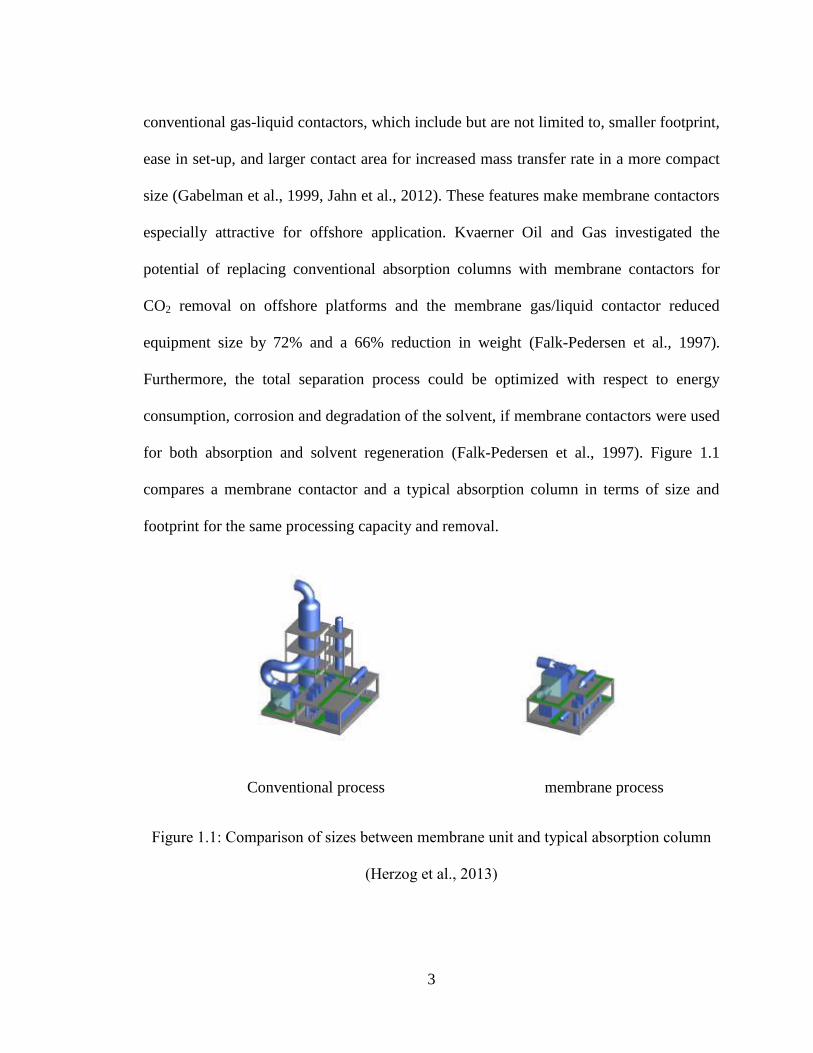
for both absorption and solvent regeneration (Falk-Pedersen et al., 1997). Figure 1.1
compares a membrane contactor and a typical absorption column in terms of size and
footprint for the same processing capacity and removal.
Conventional process membrane process
Figure 1.1: Comparison of sizes between membrane unit and typical absorption column
(Herzog et al., 2013)
4
1.1 Motivation
Since the Kvaerner membrane contactor was developed and tested for CO2 separation
from gas turbine exhaust in 1997, extensive efforts have been made in designing and
developing membrane contactors for offshore gas processing. Yet only few membrane
gas-liquid contactors have been commercialized for CO2 removal (Feron et al., 2002;
Hoff et al., 2003). In most existing membrane systems, gas absorption and solvent
regeneration take place in two separate units (Lee et al., 2001; Kosaraju et al., 2005).
PETRONAS and Cameron tested the idea of packing two types of membranes into one
unit to replace the multiple stages membrane based absorber for bulk removal of CO2 in
offshore gas fields (Isa et al., 2012). By combining two membrane contactors into one
unit, the same absorption performance can be achieved with a 50% reduction in the
equipment footprint. The possibility of achieving gas absorption and solvent regeneration
in one compact unit instead of multiple modules however has never been explored.
The absorption performance of membrane contactors depends on many factors such as
membrane material, selection of solvents, operation conditions and module design.
Compared to extensive work carried out in the development of novel membrane material
and absorbent (Khaisri et al., 2009; Wongchitphimon et al., 2011; Rajabzadeh et al.,
2013), less effort has been directed towards the process engineering aspects such as
transport phenomena and module design. Thus far, to our best knowledge, there are no
comprehensive studies have been carried out with a focus on the optimization of the
module performance by exploring novel membrane module design that suitable for
offshore use.
5
One of the most commonly used approach to reduce the operating cost is through the
optimization of the operation conditions. It can be achieved through conducting
sensitivity analysis on estimated performance of membrane module. As it is essential to
use unit models to accurately describe the process behavior in any new process, the
prediction of module performance is important in the design of membrane contactor. The
ability to experiment on the computer with alternative process setups and operating
conditions reduces the costly and time-consuming laboratory and pilot plant effort.
Prediction of the module performance for design purpose requires knowledge of the
mixing patterns and mass transfer characteristics of the membrane contactor (Dindore et
al., 2005). This is technically challenging due to the complex nature of flow through
membrane module.
1.2 Objectives
The goal of this research, therefore, is to develop and optimize a novel design of
membrane contactor that satisfies the challenges imposed by offshore. It also deals with
the assessment and optimization of hollow fiber-based membrane module design and
operation with a focus on gas absorption.
The objectives of current research include:
To design a novel membrane contactor with a reduced footprint, more compact
volume and better performance, compared to current membrane systems;
To establish a mathematical model to approximate and evaluate absorption
performance of the proposed membrane contactor;
6
To fabricate a lab scale module for the proposed membrane contactor and
experimentally test its performance;
To develop a computational fluid dynamics (CFD) based model to assist decision
making in terms of design optimization;
To evaluate alternative membrane module configurations by investigating the
impact of module geometry on gas absorption performance.
In order to achieve these objectives, the following areas are included in the scope of this
research:
At the pre-design stage, a novel membrane system for offshore gas processing is
proposed. Modelling of mass transfer process in the proposed module is carried
out to gain a better understanding of the module performance.
At the design stage, the impact of module geometry on module performance is
investigated using a customized CFD model for the optimization of module design.
At the experimental stage, a lab scale module is fabricated with its performance
tested in a lab scale flow loop. Absorption of CO2 is carried out in the proposed
module to gain a better understanding on the mass transfer process in the proposed
membrane module. Furthermore, module performance is evaluated by varying
operational conditions. Experimental results are used to validate the accuracy of
the proposed model.
7
1.3 Dissertation Structure
Chapter 1 includes a brief introduction to the background of membrane based gas
absorption as well as the description of research objectives and scope.
Chapter 2 gives a comprehensive literature review of membrane technology used
for gas processing from the perspectives of transport phenomena, selection of
module design, development of modelling approach that approximate module
performance. It is expected that this review can provide inspiration for novel
module development that serves for future offshore gas absorption.
Chapter 3 presents a novel design of dual membrane contactor which potentially
achieves gas absorption and the regeneration of solvent in the same unit. The
module design and mass transfer mechanism in the proposed module is described
in details. Following that, a mathematical model based on mass balance principle
is subsequently proposed to describe the mass transfer phenomena in the module.
The model is validated through benchmarking against published experimental
results (Dindore et al., 2005).
Chapter 4 explores the performance of the proposed membrane contactor through
experimental approach. A better understanding of mass transfer mechanisms in
the proposed module is obtained through experimental observations of CO2
removal from gas mixtures. Further, the experimental results are compared with
modelled results for validation. The effect of operational conditions such as flow
rates and pressure control are also discussed.
8
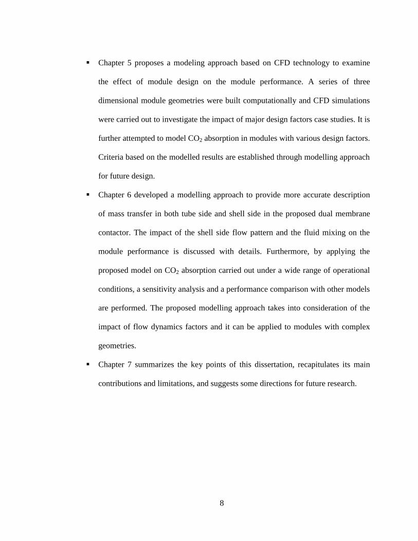
Chapter 5 proposes a modeling approach based on CFD technology to examine
the effect of module design on the module performance. A series of three
dimensional module geometries were built computationally and CFD simulations
were carried out to investigate the impact of major design factors case studies. It is
further attempted to model CO2 absorption in modules with various design factors.
Criteria based on the modelled results are established through modelling approach
for future design.
Chapter 6 developed a modelling approach to provide more accurate description
of mass transfer in both tube side and shell side in the proposed dual membrane
contactor. The impact of the shell side flow pattern and the fluid mixing on the
module performance is discussed with details. Furthermore, by applying the
proposed model on CO2 absorption carried out under a wide range of operational
conditions, a sensitivity analysis and a performance comparison with other models
are performed. The proposed modelling approach takes into consideration of the
impact of flow dynamics factors and it can be applied to modules with complex
geometries.
Chapter 7 summarizes the key points of this dissertation, recapitulates its main
contributions and limitations, and suggests some directions for future research.
9
References
Alexander, S.R., Winnick, J., Removal of hydrogen sulfide from natural gas through an
electrochemical membrane separator, AIChE Journal, 40 (4) (1994), 613-620
Dindor, V.Y., Gas purification using membrane gas absorption processes, Thesis,
University of University of Twent, 2005
Dindore, V.Y., Brilman, G. F.,Versteeg, D. W. F., Modelling of cross-flow membrane
contactors: physical mass transfer processes, Journal of Membrane Science, 251
(2005), 209-222
Dindore, V.Y., Cents, A.H.G., Brilman, D.W.F.,Versteeg, G.F., Shell-side dispersion
coefficients in a rectangular cross-flow hollow fibre membrane module, Chemical
Engineering Research and Design, 83(A3) (2005), 317-325
Esato, K., Eiseman, B., Experimental evaluation of Gore-Tex membrane Oxygenator,
Journal of Thoracic and Cardiovascular Surgery, 69(5) (1975), 690-697
Falk-Pedersen, O., Dannström, H., Separation of carbon dioxide from offshore gas
turbine exhaust, Energy Conversion and Management, 38 (1997), S81-S86
Feron, P.H.M., Jansen, A.E., CO2 separation with polyolefin membrane contactors and
dedicated absorption liquids: performance and prospects, Separation and
Purification Technology 27 (2002), 231-242
Gabelman, A., Hwang, S., Hollow fibre membrane contactors, Journal of Membrane
Science, 159 (1999), 61-106
Herzog, H., Falk-Pedersen, O., The Kvaerner membrane contactor: Lessons from a case
10
study in how to reduce capture costs, 5th International Conference on Greenhouse
Gas Control Technologies, Cairns, Australia, 2000
Hoff, K.A., Modeling and experimental study of carbon dioxide absorption in a
membrane contactor, Ph.D. Thesis, Norwegian University of Science and
Technology, Norway, 2003
Isa, F.M., Ahmad, A.S., Karim, F.A., Raham, F.H., Peters, R., Development of
innovative membrane for offshore high CO2 separation, World Gas Conference,
Kuala Lumpur, 2012
Jahn, J., Bos, P.V.D, Broeke, L.J.V.D, Evaluation of membrane processes for acid gas
treatment, SPE International and Operation Conference, Doha, Qatar, 2012
Khaisri, S., deMontigny, D., Tontiwachwuthikul, P. and Jiraratananon, R., Comparing
membrane resistance and absorption performance of three different membranes in
a gas absorption membrane contactor, Separation and Purification Technology,
65(2009), 290-297
Kosaraju, P., Kovvali, A.S., Korikov,A., Sirkar,K.K., Hollow fiber membrane contactor
based CO2 absorption-stripping using novel solvents and membranes, Industrial &
Engineering Chemistry Research, 44 (2005), 1250-1258
Lee, Y., Noble, R.D., Yeom, B.Y., Park, Y.I. Lee, K.H., Analysis of CO2 removal by
hollow fiber membrane contactors, Journal of Membrane Science, 194 (2001), 57-
67
Lothe, P., Pressurized natural gas: An effective and reliable gas solution for offshore
gas transportation, Offshore Technology Conference, Houston, Texas, USA, 2005

11
Nymeijer, D.C., Folkers, B., Breebaart, I., Mulder, M.H.V., Wessling, M., Selection of
top layer materials for gas-liquid membrane contactors, Journal of Applied
Polymer Science, 92 (2004), 323
Rajabzadeh, S., Yoshimoto S., Teramoto, M., Al-Marzouqi, M., Ohmukai, Y.,
Maruyama, T., Matsuyama, H., Effect of membrane structure on gas absorption
performance and long-term stability of membrane contactors, Separation and
Purification Technology, 108(2013), 65-73
Tabe-Mohammadi, A., A review of the applications of membrane separation
technology in natural gas treatment, Separation science and technology, 34 (1999),
2095-2111
Zhang, Z.E., Yan, Y.F., Zhang, L., Ju, S.X., Hollow fiber membrane contactor
absorption of CO2 from flue gas: Review and perspective, Global NEST Journal,
16 (2) (2014), 354-373
12
CHAPTER 2
LITERATURE REVIEW
This chapter reviews the current membrane technologies used for gas processing. In
section 2.1, an overview of gas purification using different membrane technologies will
be presented. Particularly, two possible mechanisms of mass transfer in membrane based
gas processing will be briefly explained. Section 2.2 mainly discusses gas absorption
using membrane contactors and further compares various absorbents used for gas
absorption. Section 2.3 reviews the technical benefits and limitations of existing
membrane contactors in terms of their application in gas absorption. Prior studies in
membrane contactors with various configurations, process modeling and hollow fibre
module design will also be summarized in this section. It is expected that this review can
provide insights in developing novel module that will be suitable for offshore gas
processing purpose.
2.1 Overview of Gas processing
Raw natural gas contains impurities such as H2O, CO2 and H2S that may result in hydrate
formation, corrosion and pose health and environmental hazards during transport. To
13
meet pipeline specifications and avoid potential environmental issues, removal of these
contaminants from gas streams before delivery and transportation is critical. As
mentioned in the previous section, the operations for gas processing can be classified into
four categories, in which amine absorption system is a proven, well-accepted technology
for acid gas removal in natural gas processing. In general, chemical absorption processes
using amine takes up 95 % of all gas sweetening market (Baker 2008).
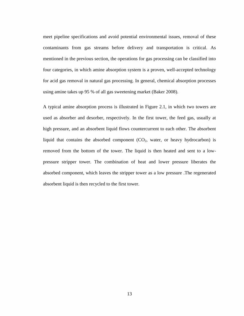
A typical amine absorption process is illustrated in Figure 2.1, in which two towers are
used as absorber and desorber, respectively. In the first tower, the feed gas, usually at
high pressure, and an absorbent liquid flows countercurrent to each other. The absorbent
liquid that contains the absorbed component (CO2, water, or heavy hydrocarbon) is
removed from the bottom of the tower. The liquid is then heated and sent to a low-
pressure stripper tower. The combination of heat and lower pressure liberates the
absorbed component, which leaves the stripper tower as a low pressure .The regenerated
absorbent liquid is then recycled to the first tower.
14
Figure 2.1 : Typical natural gas absorber-stripper treatment process using amine
absorbents to remove carbon dioxide (Baker et al., 2008)
Chemical absorption using absorber-desorber is usually conducted in heavy and bulky
towers. It requires large amounts of expensive amines to operate. Furthermore, corrosion
is a critical maintenance issue. Take acid gas removal for example, amine is the most
widely used solvent for this purpose. Degradation of amine leads to corrosive mixtures
that can destroy the system within a few days if left unchecked. Constant monitoring of
the amine absorbent is needed. The need for regular maintenance and good operator care
hinders the use of amine absorber-strippers in remote locations such as offshore platform
and this provides an incentive to develop cost effective separation technologies with
smaller footprint and easy scale-up.
15
2.2 Membrane technologies used for gas processing
As membrane technology broke into gas processing market in 1980s, it has been
receiving more and more attention in past decades as membrane processes have been
proven to be technically and economically superior to conventional absorption systems.
This superiority is due to many advantages that membrane technology benefits from,
including low capital investment, simplicity and ease of installation and operation, low
maintenance requirements, low weight and space requirements, and high process
flexibility, which makes it especially attractive for offshore gas processing (Falk-
Pedersen et al., 1997).
2.2.1 Membrane separation
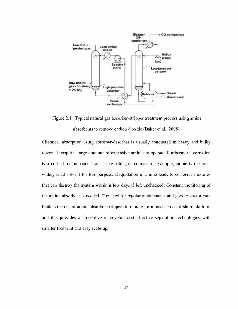
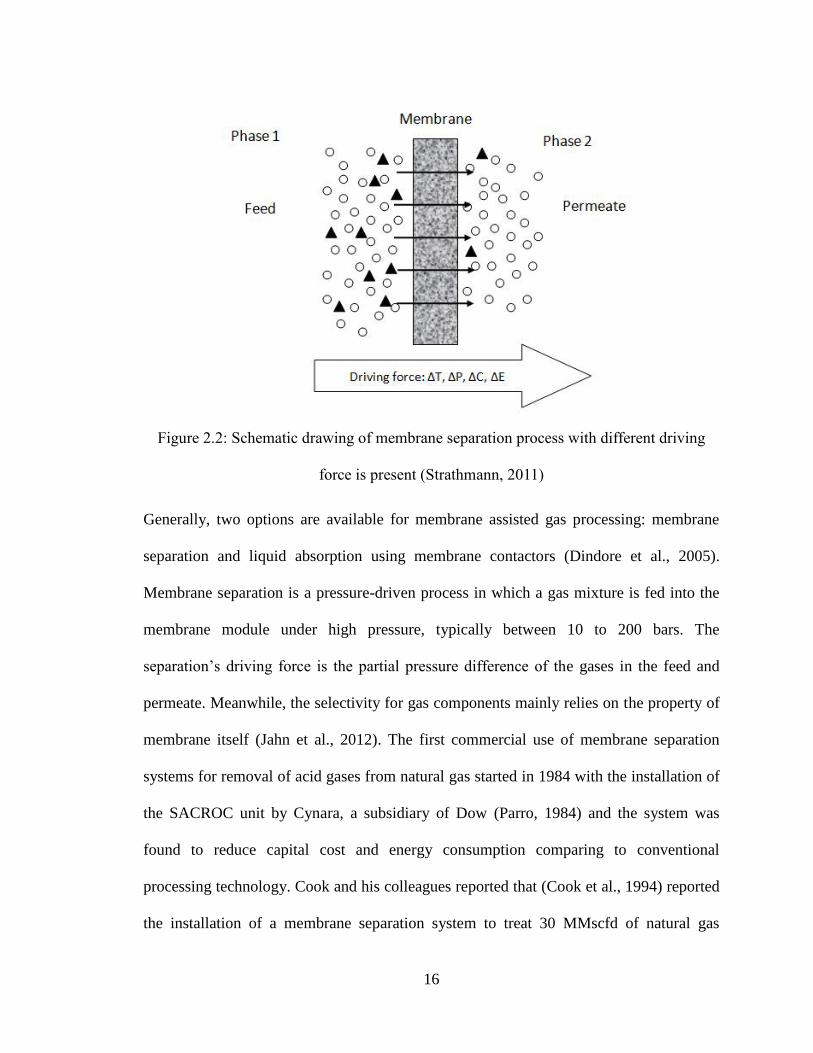
In the process of separation, membrane is set up between two bulk phase and the
movement of any specie across the membrane is a result of one or more driving forces
which can be gradients in concentration, pressure, temperature (Strathmann, 2000) or
electrical potential (shown in Figure 2.2).
16
Figure 2.2: Schematic drawing of membrane separation process with different driving
force is present (Strathmann, 2011)
Generally, two options are available for membrane assisted gas processing: membrane
separation and liquid absorption using membrane contactors (Dindore et al., 2005).
Membrane separation is a pressure-driven process in which a gas mixture is fed into the
membrane module under high pressure, typically between 10 to 200 bars. The
separation’s driving force is the partial pressure difference of the gases in the feed and
permeate. Meanwhile, the selectivity for gas components mainly relies on the property of
membrane itself (Jahn et al., 2012). The first commercial use of membrane separation
systems for removal of acid gases from natural gas started in 1984 with the installation of
the SACROC unit by Cynara, a subsidiary of Dow (Parro, 1984) and the system was
found to reduce capital cost and energy consumption comparing to conventional
processing technology. Cook and his colleagues reported that (Cook et al., 1994) reported
the installation of a membrane separation system to treat 30 MMscfd of natural gas
17
containing 11% carbon dioxide. They compared a membrane system with an
amine/glycol system and concluded that the total operating costs for both systems were
the same but the membrane system inherently offers more advantages such as flexibility
for expansion and turndown, space savings and less cost in maintenance. In a study of a
novel electrochemical membrane separator used for removal of H2S from natural gas, and
recovery of elemental sulfide and hydrogen, the membrane separator reduces the capital
cost by 50%, comparing to other conventional technologies (Alexander et al., 1994).
Despite all these advantages, the commercial utilization progress grows relatively slow
due to low selectivity and permeability of membrane to gas components. A general
tradeoff has been recognized between permeability and selectivity: Polymers that are
more permeable are generally less selective and vice versa (Tabe-Mohammadi et al.,
1999). Take CO2 removal from natural gas for example, for membranes providing high
permeability for CO2, they usually encounter problem in loss of hydrocarbon, mainly
methane into permeate side. Furthermore, as more CO2 permeates through the membrane,
its partial pressure decreases, resulting in decreasing of driving force as discussed above.
At the same time, the partial pressure of methane increases as more CO2 permeates
through the membrane. Therefore, its permeation rate increases, resulting in higher
overall methane loss. To make up for the loss of methane during this process, the idea of
multistage separation was proposed which improve the recovery rate by collecting CO2
rich permeate from the first separator and feed it into the second module. Separation
performance of single and multistage membrane systems were compared and it was
concluded that multistage system can improve methane recovery by 8% and 98% of
methane can be recovered through multistage membrane separators (Babcock et al., 1988).
18
However, the increasing number of membrane units also poses challenges to applications
on offshore platforms, where a space is a valuable commodity.
2.2.2 Gas absorption using membrane contactors
An alternative technology that overcomes the disadvantage of membrane separation is
using membrane contactors. Unlike dense membranes used in gas separation processes,
the membranes used in these types of contactors are basically non-selective in nature and
the selectivity aspect is primarily determined by the solvent used. Furthermore, the total
pressure across the membrane remains the same whereas the driving force for membrane
gas-liquid contactor comes from the concentration difference of the absorbed species,
which brings a small pressure drop and keeps the gas-liquid interface remains
immobilized at the mouth of pore (Dindore et al., 2005). In addition, the interfacial area
for mass transfer in a membrane gas-liquid contactor equals the geometrical membrane
surface area. Thus the interfacial area is constant and not influenced by orientation or
change in flow rates. The feature of orientation free area provides more flexibility for the
offshore applications. Falk-Pedersen et al. (Falk-Pedersen et al.,1997) compared
membrane gas/liquid contactor desorber to several types of desorption systems for CO2
removal from gas turbine exhaust on offshore platform and the membrane contactor
desorber was found to have the best potential. PETRONAS which has extensive
experiences in developing high CO2 offshore gas fields projects had made extensive
evaluation on several process for gas separation namely chemical absorption (amine),
physical absorption, cryogenic distillation (Ryan Holmes process), membrane system and
19
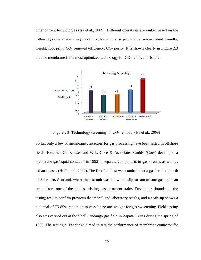
other current technologies (Isa et al., 2009). Different operations are ranked based on the
following criteria: operating flexibility, Reliability, expandability, environment friendly,
weight, foot print, CO2 removal efficiency, CO2 purity. It is shown clearly in Figure 2.3
that the membrane is the most optimized technology for CO2 removal offshore.
Figure 2.3: Technology screening for CO2 removal (Isa et al., 2009)
So far, only a few of membrane contactors for gas processing have been tested in offshore
fields. Kværner Oil & Gas and W.L. Gore & Associates GmbH (Gore) developed a
membrane gas/liquid contactor in 1992 to separate components in gas streams as well as
exhaust gases (Hoff et al., 2002). The first field test was conducted at a gas terminal north
of Aberdeen, Scotland, where the test unit was fed with a slip-stream of sour gas and lean
amine from one of the plant's existing gas treatment trains. Developers found that the
testing results confirm previous theoretical and laboratory results, and a scale-up shows a
potential of 75-85% reduction in vessel size and weight for gas sweetening. Field testing
also was carried out at the Shell Fandango gas field in Zapata, Texas during the spring of
1999. The testing at Fandango aimed to test the performance of membrane contactor for

20
gas sweetening using a physical solvent (NFM-NAM) and gas dehydration using glycol
(TEG). The results showed the potential of 60-80% reduction in footprint for gas
dehydration. For exhaust gas treatment, the membrane technology was tested as both
absorber and desorber in a number of laboratory units and in one field pilot plant. But it
was also pointed out that the potential for the membrane gas/liquid contactor used as
desorber has to be confirmed by pilot testing using real flue gas.
2.2.3 Mass transfer in membrane contactors
Membrane gas absorption is based on a gas–liquid contact across a hydrophobic porous
membrane which permits mass transfer between the two phases without dispersing one
phase into the other. Generally, the gas fills the hydrophobic membrane pores and meets
the liquid at the opposite side of the membrane. The liquid phase pressure should be
slightly higher than that of the gas phase to prevent dispersion of gas bubbles into the
liquid. As long as the excess absorbent solution pressure is less than the breakthrough
pressure of the membrane the solution does not penetrate into the pores and the gas–liquid
interface is immobilized at the pore mouth of the membrane on the liquid side. Operation
of gas–liquid membrane contactors differs from that of other membrane processes such as
filtration, since there is no convective flow through the pores and only diffusive transport
of certain components happen. This is the main reason that membrane contactors are less
sensitive to fouling than conventional membranes. As the membrane is non-selective, the
chemistry of the separation is the same as that for conventional equipment. The choice of
a suitable combination of absorption liquid, membrane characteristics and operation mode
determines the selectivity of the process.
21
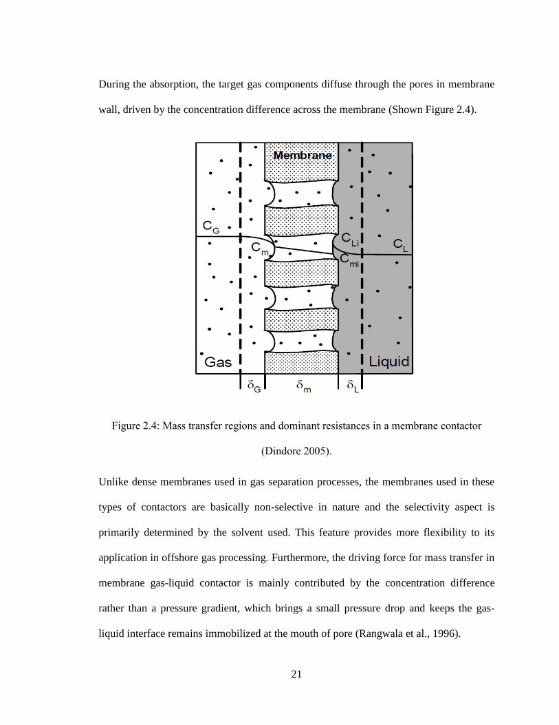
During the absorption, the target gas components diffuse through the pores in membrane
wall, driven by the concentration difference across the membrane (Shown Figure 2.4).
Figure 2.4: Mass transfer regions and dominant resistances in a membrane contactor
(Dindore 2005).
Unlike dense membranes used in gas separation processes, the membranes used in these
types of contactors are basically non-selective in nature and the selectivity aspect is
primarily determined by the solvent used. This feature provides more flexibility to its
application in offshore gas processing. Furthermore, the driving force for mass transfer in
membrane gas-liquid contactor is mainly contributed by the concentration difference
rather than a pressure gradient, which brings a small pressure drop and keeps the gas-
liquid interface remains immobilized at the mouth of pore (Rangwala et al., 1996).
22
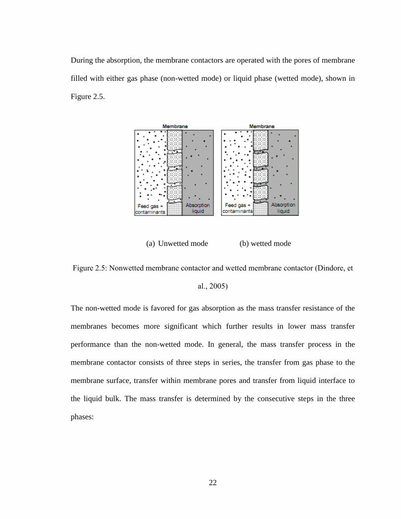
During the absorption, the membrane contactors are operated with the pores of membrane
filled with either gas phase (non-wetted mode) or liquid phase (wetted mode), shown in
Figure 2.5.
(a) Unwetted mode (b) wetted mode
Figure 2.5: Nonwetted membrane contactor and wetted membrane contactor (Dindore, et
al., 2005)
The non-wetted mode is favored for gas absorption as the mass transfer resistance of the
membranes becomes more significant which further results in lower mass transfer
performance than the non-wetted mode. In general, the mass transfer process in the
membrane contactor consists of three steps in series, the transfer from gas phase to the
membrane surface, transfer within membrane pores and transfer from liquid interface to
the liquid bulk. The mass transfer is determined by the consecutive steps in the three
phases:

23
-Transport of gaseous component i from the bulk gas to the membrane wall,
-Diffusion through the totally gas-filled pores of the membrane to the membrane–liquid
interface
-Dissolution into the liquid absorbent, followed by liquid phase diffusion and/or chemical
reaction.
Hence, a resistance-in-series model can be used to describe the total resistance (Kruenlen
et al. 1993), present in Eq. 2.1. Rtotal, defined as the reciprocal of the overall mass transfer
coefficient, Kol:
mLGol
totalk
H
kkkR
111 Eq.2.1
Where kG is the gas phase mass transfer coefficient, km is the mass transfer rate through
membrane and kl is the liquid phase resistance.
For membrane contactors operated under non-wetted mode, the resistance to gas diffusion
from the bulk gas to the membrane external surface and membrane can be ignored
compared to other resistances (Karoor et al., 1993; Rangwala et al., 1996; Dindore et al.,
2004).
To properly understand the mass transfers in the gas absorption process occurring in
membrane contactors, the concentration distributions adjacent to the membrane surfaces
along the module length should be fully described.
24
2.2.4 Modeling of mass transfer in membrane contactors
Typical approaches for predicting the shell-side mixing behavior and the mass transfer
performance either require solving the continuum mass and momentum balances based on
first principles, relying on completely empirical correlations or using a model which
contains few empirical parameters and approximates the actual behaviour closely. The
first approach would require the descretization of the complex three dimensional (3D)
geometry and solving the large sets of computationally demanding equations. However,
in many cases it is possible to assume simplified flow patterns. This approach is possible
in more simple geometries, e.g., parallel flow in shell and tube geometry without baffles.
In such cases, many researchers have assumed a simplified geometry of flow around a
single fibre and Happel’s free surface model (Chun et al., 1997; Karoor and Sirkar, 1993).
However, these simplifications do not match with the real module performance due to
uneven distribution and bending of fibres (Kreulen et al., 1993). Moreover, in the case of
the cross-flow contactor such simplification of flow pattern would result in inaccurate
description of the module performance due to the continuous splitting and remixing of the
shell-side phase. The second approach is to derive empirical correlations to predict the
mass transfer performance without knowing the details of mixing behaviour. The
experimentally derived correlations are strongly influenced by the module geometry used,
and are specific for the flow configuration. In addition, these correlations are subjected to
suffer from channeling effects, polydispersity and uneven distribution of the fibres
(Dahuron and Cussler, 1988; Wickramasinghe et al., 1992).
25
Another approach used to predict mass transfer in membrane contactors with complex
geometry is Computational Fluid Dynamics (CFD) methodology. Computational Fluid
Dynamics (CFD) methodology allows the flow of fluid to be modeled in complex
geometries and offers quick analysis of the effect of design factors. Catapano et al. [9]
and Gage et al. (Gage et al., 2002) have used this approach to treat the fibre bundles as
porous media and to perform CFD analysis of flow in fibre bundles. When compared to
experimental data, the simulation results were found agreeable.
2.3 Designing membrane contactors
Several membrane module configurations are available, both at commercial and
laboratory scale respectively, for membrane applications such as filtration, gas separation
etc. These module configurations can be conveniently adopted for the membrane gas-
liquid contactors with relatively little modifications. Depending on the type of membranes
used in the contactor, these devices can be broadly classified into two groups; the flat
sheet membrane contactor and the hollow fibre membrane contactor. Flat sheet
membranes are used in plate-and-frame or in spiral wound membrane contactors.
Although equally efficient mass transfer operation can be carried out using flat sheet
membrane contactors, hollow fibre membrane contactors are widely used due to the
higher interfacial area (shown in Figure 2.6). In a research (Gu et al. 2000) carried out on
CO2 and O2 transfer using membrane oxygenator, the pressure drop was found higher in
flat membrane module comparing to hollow fiber membrane module, which makes the
latter one more attractive.
26
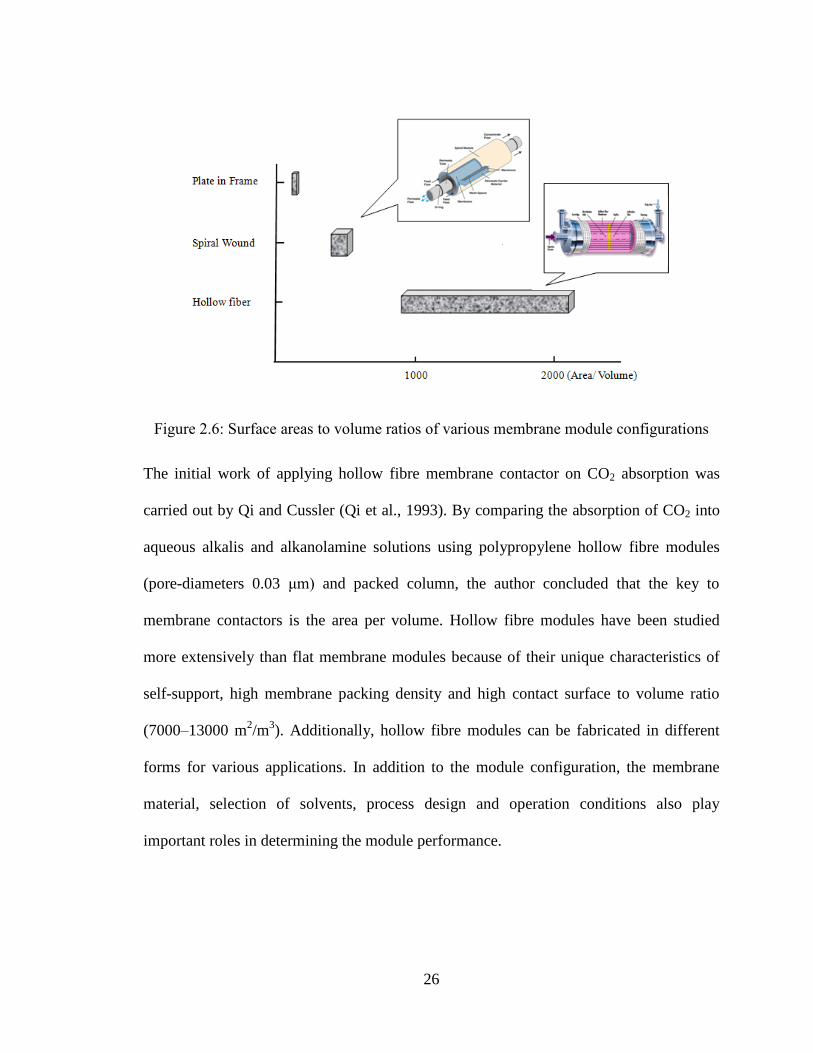
Figure 2.6: Surface areas to volume ratios of various membrane module configurations
The initial work of applying hollow fibre membrane contactor on CO2 absorption was
carried out by Qi and Cussler (Qi et al., 1993). By comparing the absorption of CO2 into
aqueous alkalis and alkanolamine solutions using polypropylene hollow fibre modules
(pore-diameters 0.03 μm) and packed column, the author concluded that the key to
membrane contactors is the area per volume. Hollow fibre modules have been studied
more extensively than flat membrane modules because of their unique characteristics of
self-support, high membrane packing density and high contact surface to volume ratio
(7000–13000 m2/m
3). Additionally, hollow fibre modules can be fabricated in different
forms for various applications. In addition to the module configuration, the membrane
material, selection of solvents, process design and operation conditions also play
important roles in determining the module performance.

27
2.3.1 Selection of absorption solvent
As the key component of the membrane contactor, selection of appropriate membrane
material and solvent is important to ensure effective module design. As explained in the
previous section, the mass transfer rate in membrane contactor is determined by the
resistance in the gas phase, liquid phase, and membrane phase. The resistance in gas
phase becomes negligible when the pores of membrane are filled with gas. However,
when the membrane pores are filled with the liquid (wetted), the mass transfer resistance
of the membranes becomes significant (Kreulen et al., 1993), resulting into economically
unviable operation. The design strategy of the membrane gas-liquid contactors for CO2
removal should be aimed at preventing the membrane wetting for long term application
by carefully selecting absorption solvent and membrane materials with good
compatibility.
Absorption of CO2 can be carried out using either physical or chemical solvents. Typical
chemical solvents include aqueous solutions of alkanolamines and aqueous carbonate
solutions. The mass transfer coefficients with the absorption of CO2 in a solution of
sodium hydroxide was examined and the result showed that the mass transfer process
was influenced by the chemical reaction between hydroxide and carbon dioxide (Qi
et al., 1993). The influence of a chemical reaction on the mass transfer by means of
simulating and testing the absorption of CO2 in KOH solution and the selective
absorption of H2S using aqueous alkanolammes was studied by several researchers
(Kreulen et al.,1993). The selectivity was determined by the ratio of the partial mass
28
transfer resistances in the gas and liquid phase and the solubility of gas component
in the absorption liquid. Aqueous monoethanolamine (MEA), 2-amino-2-methyl-1-
propanol (AMP), DEA and water were compared as absorbents to separate CO2–N2
mixture in PTFE hollow fibre membrane contactors (Kim et al., 2000). In the presence of
alkanolamines as absorbents, absorption is facilitated by chemical reaction and MEA
gives the highest CO2 removal efficiency, compared to the other absorbents.
Although amines have a long and successful track record for acid gas removal under a
variety of conditions, the processes are energy intensive and are not always the best
choice for offshore CO2 removal when the CO2 partial pressure and feed gas volumes are
high (Dindore et al., 2005). Generic amine treating processes, such as DGA, DEA, or
MDEA, require considerable heating and cooling duties for amine regeneration when
treating gas streams with a high CO2 content. On an offshore platform, amine
regeneration by steam, hot water, or heating medium requires additional equipment,
amine storage capacity, and large piping, which increases platform cost. Physical
absorption using membrane can be operated under low temperature and makes
regeneration of absorbents much easier. Furthermore, unlike chemical absorption, the
amount of CO2 absorbed by the solvent is determined by the vapour-liquid equilibrium of
the mixture, which is governed by partial pressure and temperature. At high CO2 partial
pressure, the CO2 loading capacity of the solvent is higher for a physical solvent than for
a chemical solvent. Physical absorption processes are thus particularly appropriate for the
treatment of CO2-rich gas streams. CO2 absorption using water as absorbent was
investigated from which several empirical correlations for membrane contactors with
29
absorbent inside and outside the hollow fibres were presented (Yang et al., 1986). The
performance of the cross flow hollow fibre membrane contactor (HFMC) for CO2
absorption using water and propylene carbonate and both of them shows great
compatibility with Propylene hollow fibres, which brings potential for long term
operation. Wang et al. (Wang et al., 2006) developed detailed numerical model to analyze
the absorption of CO2 and H2S using methanol in flat sheet membrane and the absorption
efficiency can be as high as 85%.
Both chemical absorption and physical absorption have their own advantages and
disadvantages, there is one common issue shared by these two operations: wetting of the
membrane. As explained earlier, when the pores of membrane are filled with liquid
(wetted mode), the overall mass transfer rate dramatically decreases due to the increasing
in mass transfer resistance. In general, the wetting of the membrane is decided by the
membrane–liquid interactions. Hence, a suitable combination of the absorption liquid and
the membrane material is critical for the stability of the membrane gas-liquid contactors.
2.3.2 Selection of membrane material
For porous membranes, a minimum pressure is required for the liquid to penetrate into the
pores. The higher breakthrough pressure is a key for the long term non-wetting
application of gas-liquid membrane contactors. A few researchers explored the criteria of
the selection of appropriate membrane-solvent combination for the development of
membrane gas absorption (Dindore et al., 2005). The compatibility of organic solvents
with several commercially available membrane materials were studied by examining the
critical entry pressure, the contact angle of the liquid on the membrane surface and the

30
size and shape of membrane pores. Membranes having a high hydrophobicity and low
surface energies such as PTFE, polypropylene, PVDF, polysulfone and polyethersulfone
were selected.
Table 2.1: Membrane-solvent compatibility (Dindore et al., 2005)
Compared to other membranes, PTFE and polypropylene membranes were found to be
compatible with some of the selected organic solvents in terms of less morphological
damage, swelling, shrinkages, color change or dissolution after being exposed to selected
solvents over a period of time. Compared to PP membrane, the application of PTFE is
limited for its high production cost and is unavailable in small diameters while the
hydrophobicity of PP membranes can be improved by various modification methods, such
as pretreatment with fluorocarbonic material (Nishikawa et al., 1995), surface grafting
(Xu et al., 2002), interfacial polymerization (Dickson et al., 1998) and solvent casting
(Erbil et al., 2003). Therefore, PP membrane is considered as the potential candidate for
designing membrane contactors for offshore gas processing in this work.
31
2.3.3 Operation modes of membrane contactors
Several membrane module configurations are available, both at commercial and
laboratory scale respectively, for the conventional membrane applications such as
filtration, gas separation etc. These module configurations can be conveniently adopted
for the membrane gas-liquid contactors with relatively little modifications. Depending on
the type of membranes used in the contactor, these devices can be broadly classified into
two groups; the flat sheet membrane contactor and the hollow fiber membrane contactor.
Flat sheet membranes are used in plate-and-frame or in spiral wound membrane
contactors. Although equally efficient mass transfer operation can be carried out using
flat sheet membrane contactors, hollow fiber membrane contactors are widely used due to
the higher interfacial area. Based on the flow directions of the gas and liquid phase, the
hollow fiber membrane contactor can be used in two different modes of operation, shown
in Figure 2.7 (Dindore et al., 2005).
- Parallel flow mode: The flow of the both phases is parallel to the axis of the fiber and
both fluids flow either in same direction (co-current) or in opposite direction (counter
current).
- Cross flow mode: The flow of one of the fluid is perpendicular to the axis of fiber and
other fluid flows parallel to the axis of fiber. Thus the two fluids flow at right angles to
each other.
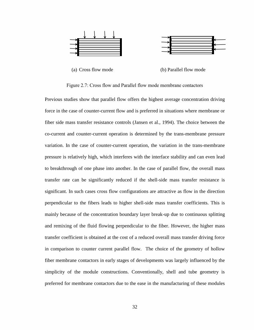
32
(a) Cross flow mode (b) Parallel flow mode
Figure 2.7: Cross flow and Parallel flow mode membrane contactors
Previous studies show that parallel flow offers the highest average concentration driving
force in the case of counter-current flow and is preferred in situations where membrane or
fiber side mass transfer resistance controls (Jansen et al., 1994). The choice between the
co-current and counter-current operation is determined by the trans-membrane pressure
variation. In the case of counter-current operation, the variation in the trans-membrane
pressure is relatively high, which interferes with the interface stability and can even lead
to breakthrough of one phase into another. In the case of parallel flow, the overall mass
transfer rate can be significantly reduced if the shell-side mass transfer resistance is
significant. In such cases cross flow configurations are attractive as flow in the direction
perpendicular to the fibers leads to higher shell-side mass transfer coefficients. This is
mainly because of the concentration boundary layer break-up due to continuous splitting
and remixing of the fluid flowing perpendicular to the fiber. However, the higher mass
transfer coefficient is obtained at the cost of a reduced overall mass transfer driving force
in comparison to counter current parallel flow. The choice of the geometry of hollow
fiber membrane contactors in early stages of developments was largely influenced by the
simplicity of the module constructions. Conventionally, shell and tube geometry is
preferred for membrane contactors due to the ease in the manufacturing of these modules
33
(Wickramasinghe et al., 1993). Later on, several investigators found that uneven packing
and uneven flow distribution on the shell side of the shell and tube module resulted into
reduced mass transfer rates (Wang et al., 2003). Hence considerable efforts have been
made to explore the different module geometries in order to achieve uniform flow
distribution on the shell side. In recent years, it has also been found that the use of fibers
woven into fabric in the membrane module manufacture results in more uniform fiber
spacing (Dindore et al., 2005) The fibers woven into a fabric have been successfully used
for the manufacturing of module with different geometries such as rectangular module,
helically wound fiber module, baffled shell and tube module and transverse flow module.
Out of the various innovative geometries studied by several investigators, only
rectangular module and shell and tube transverse flow module have been successfully
commercialized. Hoechst Celanese provides shell and tube transverse flow Liqui-Cel
contactors for various gas-liquid contacting applications where as rectangular cross-flow
module is commercialized by TNO Environmental Energy and Process Innovation (The
Netherlands) and by Kvaerner Oil & Gas in co-operation with W. L. Gore & Associates
GmbH. Mass transfer in hollow fiber membrane modules with different geometries was
compared with equal flow per membrane area and it was found that the flow outside and
across the fibers is at least ten times more effective than flow outside and parallel to the
fibers (Wickramasinghe et al., 1993). A similar conclusion was drawn based the
experimental study of reactive absorption of SO2; the mass transfer coefficient for the
cross flow modules was one order of magnitude higher than parallel flow modules
(Jansen et al., 1994).
34
References
Alexander, S.R., Winnick, J., Removal of hydrogen sulfide from natural gas through an
electrochemical membrane separator, AIChE Journal, 40 (4) (1994), 613-620
Babcock, R.E.,Spillman, R.W., Goddin, C.S., Cooley, T. E., Natural Gas Cleanup: A
Comparison of Membrane and Amine Treatment Processes, Energy Progress,
8(3)(1988), 135-142
Baker, R.W., Lokhandwaa, K., Natural Gas Processing with Membranes: An Overview,
Ind. Eng. Chem. Res. 47 (2008), 2109-2121
Baker, R.W., Roman, I.C., Lonsdale, H.K., Liquid membranes for the production of
oxygen-enriched air I. Introduction and passive liquid membranes, Journal of
Membrane Science,31 (1987), 15-29
Catapano, G., Papenfuss, H.D., Wodetzki, A., Baurmeister, U., Mass and momentum
transport in extra-luminal flow (ELF) membrane devices for blood oxygenation,
Journal of Membrane Science, 184 (2001), 123-135
Chun, M.S., Lee, K.H., Analysis on a hydrophobic hollow fiber membrane absorber and
experimental observations of CO2 removal by enhanced absorption. Separation
Science and Technology 32 (15) (1997), 2445-2466
Cook, P.J., Losin, M.S., Membranes provide cost effective natural gas Processing,
Hydrocarbon Processing, (1994), 79-84
35
Dickson, R.M, Norris, D.J, Moerner, W.E, Simultaneous imaging of individual molecules
aligned both parallel and perpendicular to the optic axis Physical Review Letter,
81(1998) 5322-5325
Dindore, V.Y., Brilman, D.W.F., Versteeg, G. F., Hollow fibre membrane contactor as a
gas–liquid model contactor, Chemical Engineering Science, 60 (2005), 467-479
Dindore, V.Y., Versteeg, G.F., Gas-liquid mass transfer in a cross-flow hollow fibre
module: Analytical model and experimental validation, International Journal of Heat
Mass Transfer 48 (2005), 3352-3362
Esato, K., Eiseman, B., Experimental evaluation of gore-tex membrane oxygenator,
Journal of Thoracic and Cardiovascular Surgery, 69(5) (1975), 690-697
Erbil, H. Y., Demirel, A.L., Avci, Y., Mert, O., Transformation of a simple plastic into a
superhydrophobic surface, Americal Association for the Advancement of Science,
299(5611)(2003),1377-1380
Falk-Pedersen, O., Dannström, H., Separation of carbon dioxide from offshore gas
turbine exhaust, Energy Conversion Management, 38 (1997), S81-S86
Gage, K.L., Gartner, M.J., Burgreen, G.W., Wagner, W.R., Predicting membrane
oxygenator pressure drop using computational fluid dynamics, Artificial Organs 26
(2002), 600-607
Gu, Y.J., Boonstra, P.W., Graaff, R., Rijnsburger, A. A., Mungroop, H., Oeveren, W.V.,
Pressure drop, shear stress, and activation of leukocytes during cardiopulmonary
36
bypass: a comparison between hollow fibre and flat sheet membrane oxygenators,
Artifiicial Organs 24(1) (2000), 43-8
Hoff, K.A., Poplsteinova, J., Jakobsen, H.A., Juliussen, O., Falk-Pedersen, O., Sevendsen,
H.F., Modelling of membrane reactor, International Journal of Chemical Reactor
Engineering, 1(1)(2009),A9
Isa, M.F., Azhar, M. A., Meeting technical challenges in developing high CO2 gas field
offshore, 24th World Gas Conference, Buenos Aries, Argentina,2009
Jahn, J., Bos, P.V.D, Broeke, L.J.V.D, Evaluation of membrane processes for acid gas
treatment, SPE International and Operation Conference, Doha, Qatar, 2012
Jansen, A.E., Klaassen, R., Feron, P.H.M., Hanemaaijer, J.H., Meulen, B.P., Membrane
gas absorption processes in environmental applications in Membrane Processes in
Separation and Purification, Kluwer Academic Publishers, Dordrecht, 1994
Jassim, M.S., Rochelle, G.T., Innovative Absorber/Stripper Configurations for CO2
Capture by Aqueous Monoethanolamine, Industrial & Engineering Chemistry
Research, (2006), 45:2465
Johnson, B.M., Baker, R.W., Matson, S.L., Smith, K.L., Roman, I.C., Tuttle, M.E.,
Lonsdale, H.K., Liquid membranes for the production of oxygen-enriched air II.
Facilitated-transport membranes, Journal of Membrane Science, 31 (1987), 31-67
Karoor, S., Sirkar, K.K., Gas absorption studies in microporous hollow fibre membrane
modules, Ind. Eng. Chem. Res., 32 (4) (1993) 674–684
37
Kim, Y., Yang, S., Absorption of carbon dioxide through hollow fibre membranes using
various aqueous absorbents, Separation and Purification Technology, 21(1-2) (2000),
101-109
Kosaraju, P., Kowali, A. S., Korikov, A., Sirkar, K., Hollow fibre membrane contactor
based CO2 absorption-stripping using novel solvents and membranes, 44(5)
(2005), 1250-1258
Kreulen, H. Versteeg, G.F., Smolders, C.A., Swaaij, W.P.M.V., Microporous hollow
fibre membrane modules as gas-liquid contactors II: Mass transfer with chemical
reaction. Journal of Membrane Science78(3) (1993b), 217-238
Kreulen, H., Smolders, C.A., Versteeg, G.F., Swaaij, W.P.M.V., Microporous hollow-
fibre membrane modules as gas–liquid contactors: 1. Physical mass transfer
processes—a specific application: mass transfer in highly viscous liquids. Journal of
Membrane Science, 78(1993) (3), 197–216
Nishikawa, N., Ishibashi, M., Ohta, H., Akutsu, N., Mastsumoto, H., Kamata, T. ,
Kitamura, H., CO2 removal by hollow fiber gas liquid contactor. Energy Conversion
and Management 36(1995)415-418
Parro, D., “Membrane CO2 proves out at SACROC tertiary recovery project,” Oil Gas
Journal, 82 (1984), 85-88
Poddar, T.K., Majumdar S., and K.K. Sirkar, Membrane-based Absorption of VOCs from
a Gas Stream, AIChE J, 42(11) (1996), 3267-3282
38
Rangwala, H.A., Absorption of carbon dioxide into aqueous solution using hollow fibre
membrane contactors, Journal of Membrane Science, 112(1996), 229-240
Strathmann, H. Membranes and Membrane Separation Processes; Wiley-VCH Verlag
GmbH & Co. KGaA: New York, 2000
Tabe-Mohammadi, A., A review of the applications of membrane separation
technology in natural gas treatment, Separation science and technology, 34 (1999),
2095-2111
Tierling, S., Jindal, S., Abascal, R., Considerations for the use of carbon dioxide removal
membranes in an offshore environment offshore technology conference, Offshore
Technology Conference, Rio de Janeiro, Brazil, 2011
Wang, S.Y., Hawboldt, K., Abdi, M.A., Novel dual-membrane gas-liquid contactors:
modeling and concept analysis, Industrial & Engineering Chemistry Research 45
(2006), 782-789
Wang, Y. Chen, F., Wang, Y., Luo, G., Dai, Y., Effect of random packing on shell-side
flow and mass transfer in hollow fibre module described by normal distribution
function, Journal of Membrane Science 216 (2003), 81-93
Wickramasinghe, S. R., Semmens, M. J., Cussler, E. L., Hollow fibre modules made with
hollow fibre fabric, Journal of Membrane Science, 84(1) (1993),1-14
Wickramasinghe, S.R., Semmens, M. J., Cussler, E.L., Mass transfer in various hollow
fibre geometries. Journal of Membrane Science, 69(1992), 235-250
39
Xu, Z., Wang, J., Shen, L., Men, D., Xu, Y., Microporous polypropylene hollow fiber
membrane: PartI. Surface modification by the graft polymerization of acrylic acid,
Journal of membrane Science, 196 (2002), 221-229
Zhang, Q., Cussler, E.L., Microporous hollow fibres for gas absorption II. Mass transfer
across the membrane, Journal of Membrane Science, 23 (1985), 333-345
Zhang, Q., Cussler, E.L., Microporous hollow fibres for gas absorption I. mass transfer in
the liquid, Journal of Membrane Science, 23 (1985), 321-332
40
CHAPTER 3
DEVELOPMENT OF NOVEL DUAL MEMBRANE
CONTACTOR FOR GAS ABSORPTION
This chapter is based on and modified based on the following paper
Cai, J.J., Hawboldt, K., Abdi, M.A, Contaminant Removal from Natural Gas using Dual
Hollow Fiber Membrane Contactors. Journal of membrane science, 377-378 (2012)9-16
41
Having discussed the recent trends of membrane technology and its potential for gas
processing in Chapter 2, this chapter focuses on the development of novel membrane
contactors for offshore gas absorption. Conventional membrane gas-liquid contactors
have typically had separate absorption and regeneration system, which may not be
practical for offshore gas treating due to limited space. Therefore, a novel design of
membrane modules containing two sets of membranes is proposed in this chapter to
achieve gas absorption and partial solvent regeneration in one unit operation. The
motivation is presented in Section 3.1 whereas the details of the proposed dual membrane
module are given in Section 3.2. To predict the performance of the dual membrane
contactor and also the concentration change in both gas and liquid phase in the proposed
modules, a numerical model based on mass balance is developed and presented in Section
3.3. In Section 3.4, the proposed numerical model is validated by comparing the modeled
results and experimental measurements for CO2 absorption. To further demonstrate the
efficiency of the proposed dual membrane modules, its performance is also compared
with ordinary membrane module for CO2 absorption by varying operational conditions in
the same section.
3.1 Background
In gas absorption, the absorbent must be regenerated. Compared to the extensive study in
gas absorption using membrane technology, limited work has been done on the
development of membrane based regeneration. For gas treatment, regeneration of
absorbent is important to ensure process efficiency and keep solvent costs down. A
hollow fibre membrane based absorption-stripping system was proposed to remove the
42
volatile organic compounds (VOCs) from nitrogen (Poddar et al., 1996). The spent
absorbent liquid was regenerated in a separate hollow fibre stripper by applying vacuum
through the tube side and recycled back to the absorber. Falk-Pedersen et al. (Falk-
Pedersen et al., 1997) compared membrane gas/liquid contactor desorber to several types
of desorption systems for CO2 removal from gas turbine exhaust on offshore platform and
the membrane contactor desorber was found to have the best potential. Kosaraju et al.
(Kosaraju et al., 2005) studied the stripping of a novel non-volatile solvent for CO2
removal. Membrane based gas absorption and stripping were used in these studies.
However, the absorber and desorber were separate modules. Considering limited space on
offshore platform, merging the absorber and stripper into one unit would be preferred to
further minimize space and weight requirement. One option to achieve this goal is to use
immobilized liquid membrane (ILM) (Teramoto et al., 1986; Hughes et al., 1986; Baker
et al., 1987; Johnson et al., 1987; Kreulen et al., 1993). In this case, the liquid membrane
is located in the pores of the membrane, forming a thin partition between the feed gas and
stripping phase. However, the difficulty in renewal of the liquid membrane in pores
(Mataon et al., 1983), critical problems in humidity control and lack of mechanical
stability (Kimura et al., 1980) are issues that still need to be fully addressed. Contained
liquid membrane (CLM) (Majumdar et al., 1988) has been proposed to eliminate
aforementioned shortcomings. In CLM operation, a thin film of aqueous solution is held
stationary in the interstitial space between two independent sets of microporous hollow
fibres, where one set fibres carries a feed gas while the other set carries a sweep gas
stream. This design may result in large mass transfer resistance through the layer of the
membrane solution due to absorption of carrier solution in the pore of the microporous
43
membranes. In the aim of reducing the diffusion resistance of the liquid film, a new type
of “flowing liquid membrane” was proposed for separation of ethane/ethylene, in which
liquid was pumped between two microporous membranes (Teramoto et al., 1989). It was
found to provide better permeability and stability than the stationary solvent. A similar
idea was proposed by Bessarabov et al. (Bessarabov et al., 1993), using an integrated
membrane system with a solution of silver nitrate flowing between two nonporous
PVTMS membranes for separation of CO2/H2/CH4 mixtures. This type of module has
three outlets for the products and provides a higher selectivity of separation and flexibility
of the gas separation.
The development of ILM and CLM shows potential in regenerating the solvent in the
same unit as absorber by introducing vacuum or sweeping gas on the permeate side of the
membrane. However, there is little published work on how the partial regeneration of
solvent impacts gas absorption and removal efficiency. A dual membrane gas-liquid
contact concept was proposed for CO2 and H2S removal using methanol, in which two
types of flat membranes are housed into one unit (Wang et al.,m 2006). The circulating
solvent of methanol is partially regenerated during the absorption. It was demonstrated
that the gas removal efficiency can be substantially improved by introducing sweeping
gas or vacuum on the permeate side of the membrane. However, only flat membrane
under parallel flow mode (co-current or counter-current) was studied. The performance of
parallel and cross flow based on the equal flow per membrane area and found that cross
flow membrane were more effective as compared to parallel flow modules
(Wickramasinghe et al., 1992). A similar conclusion was drawn from a study of reactive
44
absorption of SO2; the mass transfer coefficient for the cross flow modules was one order
of magnitude higher than parallel flow modules (Jansen et al., 1996). To analyze the
performance of the cross flow hollow fibre membrane contactor for CO2 absorption, a
detailed numerical model was developed (Dindore et al., 2005). The regeneration of
solvent, however, was not included in their studies. This work aims to propose a new
design of hollow fibre membrane contactor to improve gas absorption by partially
regenerating the absorbent during absorption through nonporous membrane.
3.2 Dual membrane contactors
In the present study, two configurations of dual membrane HFMC were proposed with
their performance investigated. The proposed modules comprise two types of hollow
fibres. The porous hollow fibres containing feed gas are in the same contactor as
nonporous fibres, which are used for solvent regeneration. An aqueous solution flows
through shell side. In Module I (outlined in Figure 3.1(a)), a low pressure is maintained
on the permeate side of nonporous membrane. As indicated previously, the differential
pressure across nonporous membrane can improve contaminant removal from the solvent
and partially regenerate the solvent stream simultaneously with the absorption process.
This results in better absorption efficiency. To further improve the removal efficiency,
baffles are added in Module II (shown in Figure 3.1(b)). Based on studies conducted by
Wang and Cussler (Wang et al., 1992) and those in heat exchanger, the baffles can
improve mass transfer efficiency by minimizing shell-side bypass and providing a
velocity component normal to the membrane surface.
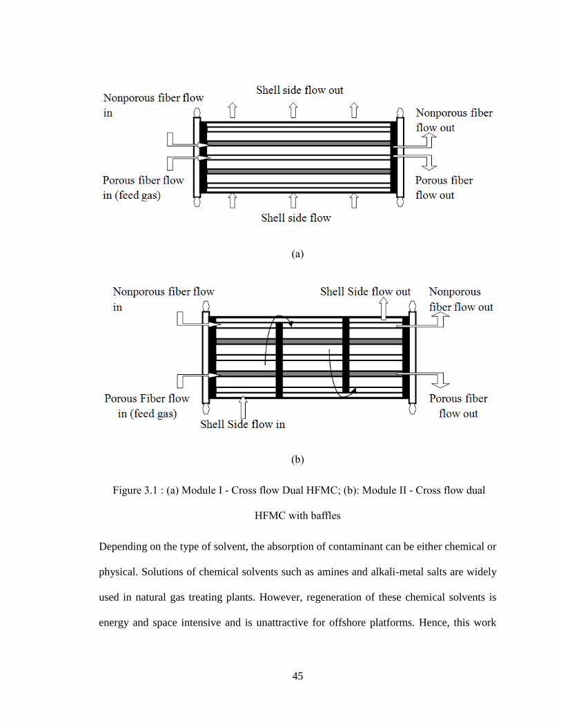
45
(a)
(b)
Figure 3.1 : (a) Module I - Cross flow Dual HFMC; (b): Module II - Cross flow dual
HFMC with baffles
Depending on the type of solvent, the absorption of contaminant can be either chemical or
physical. Solutions of chemical solvents such as amines and alkali-metal salts are widely
used in natural gas treating plants. However, regeneration of these chemical solvents is
energy and space intensive and is unattractive for offshore platforms. Hence, this work
46
mainly focuses on physical solvents. To analyze and predict the absorption performance
of the proposed modules, a mathematical model has also been developed. A similar
model was proposed for the first time to examine heat transfer in cross flow shell and tube
heat exchanger (Hoffman, 2000). Dindore et al. (Dindore et al., 2005) also proposed a
similar model for cross flow HFMCs. Predictions from the derived analytical expressions
matched well with experimental data over a range of wide operating flow rates. In their
studies, liquid was fed through membrane fibre side, which contributes most mass
transfer resistance and the impact of regeneration was not included. A numerical model
for liquid phase flowing in shell side was developed in this work to predict module
performance. It takes impact of regeneration into consideration on absorption at the same
time. The results were validated by previous experiment data from Dindore et al.
(Dindore et al., 2005). Further, absorption performance of proposed module for CO2
removal is compared with ordinary membrane module. Because two different types of
membrane were employed in the module, the effect of different packing fraction for each
type of membrane is also investigated.
3.3 Model Development
A number of researchers have modeled cross flow HFMC using iterative methods, finite
differences, and heat transfer analogies (Zhang et al., 1985; Wang et al., 1993; Dindore et
al., 2005) whereas most of these processes involve mass transfer through only one type of
membrane. To describe mass transfer taking place in dual membrane contactors, a
numerical model was developed to describe the mass transfer in the membrane, liquid
47
phase and the gas phase. The model is based on the following simplifying assumptions
(Coelhoso et al., 2000):
1. Contactor is operated under steady state and isothermal conditions.
2. Physical properties including diffusion coefficient, Henry’s constant, density,
viscosity etc. are constant along the membrane.
3. No chemical reaction is involved, only physical mass transfer is modeled.
4. Membranes are under the non-wetted mode (gas-filled pores).
5. The pressure in gas phase is constant along the membrane.
6. The flow rate of fluid in the shell side is assumed to be steady through the
contactor.
3.3.1 Overall mass transfer in liquid phase
Using the above assumptions, a material balance is applied on a differential segment of
the module. The change of mass in liquid phase is due to loss of contaminant in gas in
porous hollow fibre and gain of contaminant in the nonporous hollow fibre, it can be
expressed as follows:
npGGLL qCQCQ Eq. 3.1
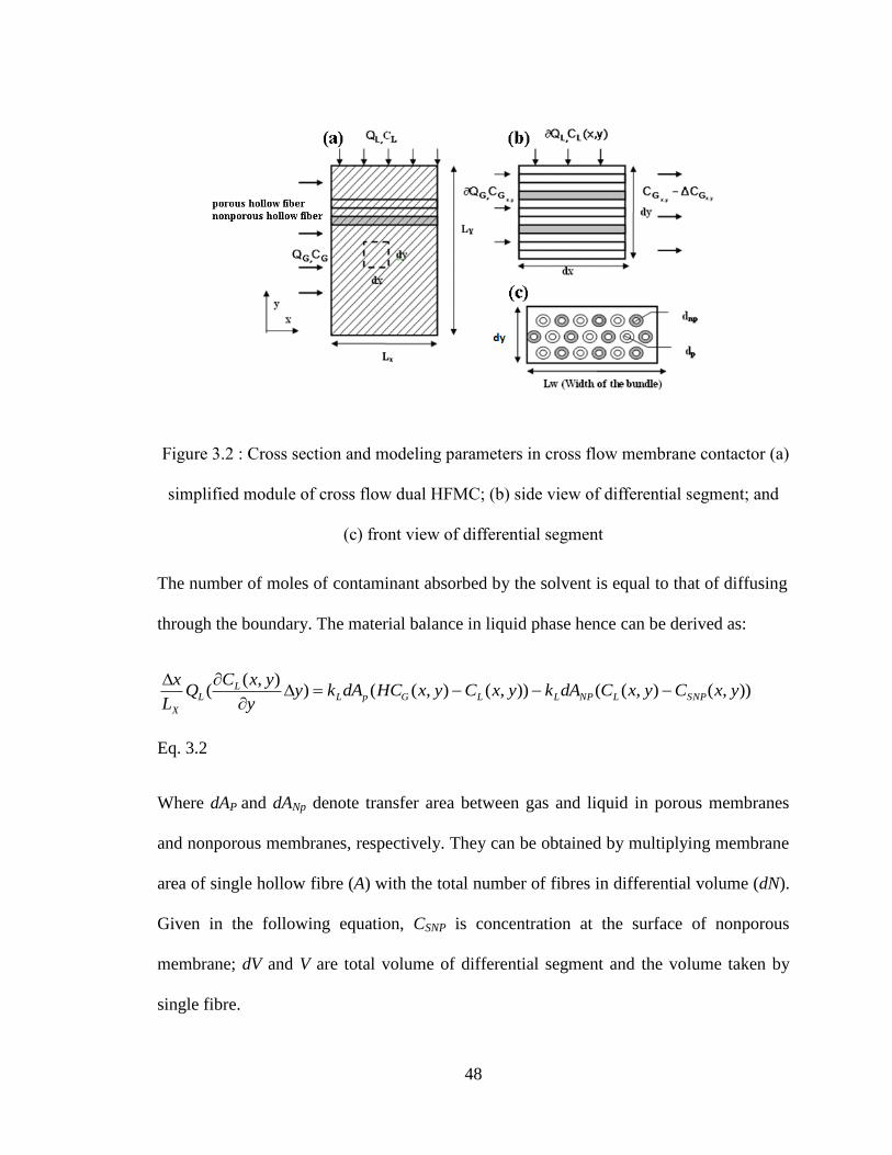
48
Figure 3.2 : Cross section and modeling parameters in cross flow membrane contactor (a)
simplified module of cross flow dual HFMC; (b) side view of differential segment; and
(c) front view of differential segment
The number of moles of contaminant absorbed by the solvent is equal to that of diffusing
through the boundary. The material balance in liquid phase hence can be derived as:
)),(),(()),(),(()),(
( yxCyxCdAkyxCyxHCdAkyy
yxCQ
L
xSNPLNPLLGpL
LL
X
Eq. 3.2
Where dAP and dANp denote transfer area between gas and liquid in porous membranes
and nonporous membranes, respectively. They can be obtained by multiplying membrane
area of single hollow fibre (A) with the total number of fibres in differential volume (dN).
Given in the following equation, CSNP is concentration at the surface of nonporous
membrane; dV and V are total volume of differential segment and the volume taken by
single fibre.
49
Eq. 3.3
Eq. 3.4
where (1- αP) and (1- αNP) denote the packing fractions of porous membranes and
nonporous membranes in the modules. By introducing these two parameters into the
model, the impact of ratio of porous membranes and nonporous membranes on the
absorption efficiency can be revealed. By introducing two new variables, the steady state
mass transfer balance in the porous fibre can be simplified as:
)),(),(()),(),((),(
yxCyxCMyxCyxHCMy
yxCSNPLNPLGp
L
Eq. 3.5
Where two new variables can be defined as: ; Eq. 3.6
Eq. 3.7
At the gas entrance where x is equal to zero, CL is a function of y only, thereby, we have
the following boundary condition:
Eq. 3.8
This expression can be solved as one of the boundary conditions on the gas side. The
second boundary condition can be defined as:
P
PPPPV
dVAdNAdA
)1(
NP
NPNPNPNPNP
V
dVANAdA
)1(
L
L
P
XWPP
Q
k
d
LLM
)1(4
L
L
NP
XWNPNP
Q
k
d
LLM
)1(4
)()( 000 SNPxLNPxLGPxL CCMCHCM
y
C
50
, at y=0 Eq. 3.9
3.3.2 Gas phase mass balance within porous membrane
The transfer of contaminant molecules from gas phase to the liquid consists of three steps:
transfer from bulk of the gas phase to the membrane, diffusion through the gas-filled
pores, and transfer from membranes into bulk of the liquid phase. The mass balance in the
gas phase can be expressed as:
)),(),(()),(
( yxHCyxCKdAxx
yxCQ
L
yGLp
GL
Y
Eq. 3.10
where K is the overall mass transfer coefficient equal to kL in this model since the
membrane and the gas phase resistance can be neglected in non-wetted gas absorption,
mass transfer is controlled by liquid phase under this mode. kL can be obtained from
Sherwood number (kd/D) and empirical equations (Wickramasinghe et al.,1992)
Eq. 3.11
Where the Reynolds number is calculated from the outer fibre diameter, the kinematic
viscosity and superficial velocity; Schmidt number (ν/D) dependence is verified by other
experiments (Mavroudi et al., 2006). Equation 3.10 can be simplified as follows by
introducing a new variable.
)),(),((),(
yxHCyxCMx
yxCGLG
G
Eq. 3.12
iinI LL CC,
33.086.0Re18.0 ScSh
51
where the new variable can be defined as:
Eq. 3.13
The boundary conditions are
, at x=0 Eq.
3.14
And the liquid entrance where y is equal to zero, the contaminant concentration in the gas
phase is a function of module length x:
Eq. 3.15
This expression is the boundary condition on the liquid side.
3.3.3 Gas phase mass balance with nonporous membranes
The contaminant absorbed in the liquid phase permeates the nonporous membrane
through diffusion mechanism. The flux is proportional to partial pressure difference and
inversely proportional to the membrane thickness:
xdPH
RTC
t
kq NPout
SNP
NP
PerNP )( Eq. 3.16
Where, Kper denotes nonporous permeability for the gas contaminant and the membrane
thickness tNP is assumed to be small and therefore the outer and inner surface areas are
equal. Similar analysis is also applied to the baffled module, each segment of Module II
can be modeled by a set of partial differential equations; the outlet concentrations of the
G
L
P
YWP
GQ
k
d
LLM
)1(4
iinI GG CC,
)( 00 ,
,
yGLGy
G
iiiin
iinHCCM
x
C
52
previous segment in both gas and liquid phases are the initial and boundary conditions for
the next segment.
The nonlinear partial differential equations established based on the mass balance in gas
phase Eq. (3.12) and liquid phase (Eq. 3.5), respectively. Each equation contains two
variables (CG, CL) in which each variable is a function of module length (x) and height (y).
To describe the concentration change in both gas and liquid phase, these two partial
differential equations were combined and solved using finite difference method in
Maple® software.
3.4 Results and discussion
The results of models were firstly compared to the experiment data to validate the
proposed model for absorption of CO2 using water. In the following, the absorption of
CO2 from CO2/CH4 mixture gases of the novel dual-membrane Module I and Module II
were investigated and the results were compared to the ordinary single membrane
contactor under the same operating conditions. Propylene carbonate was assumed to be
the absorbing solvent instead of water due to its high solubility to CO2. The effect of
different packing fractions of porous and nonporous membranes on the absorption
efficiency was also investigated for future module construction reference.
3.4.1 Model validation
To validate the numerical model, the results were compared to the experimental data from
Dindore et al. (Dindore et al., 2005). The module developed by Dindore differs from
proposed module that the liquid solvent flows through the fibres and the mixture gas
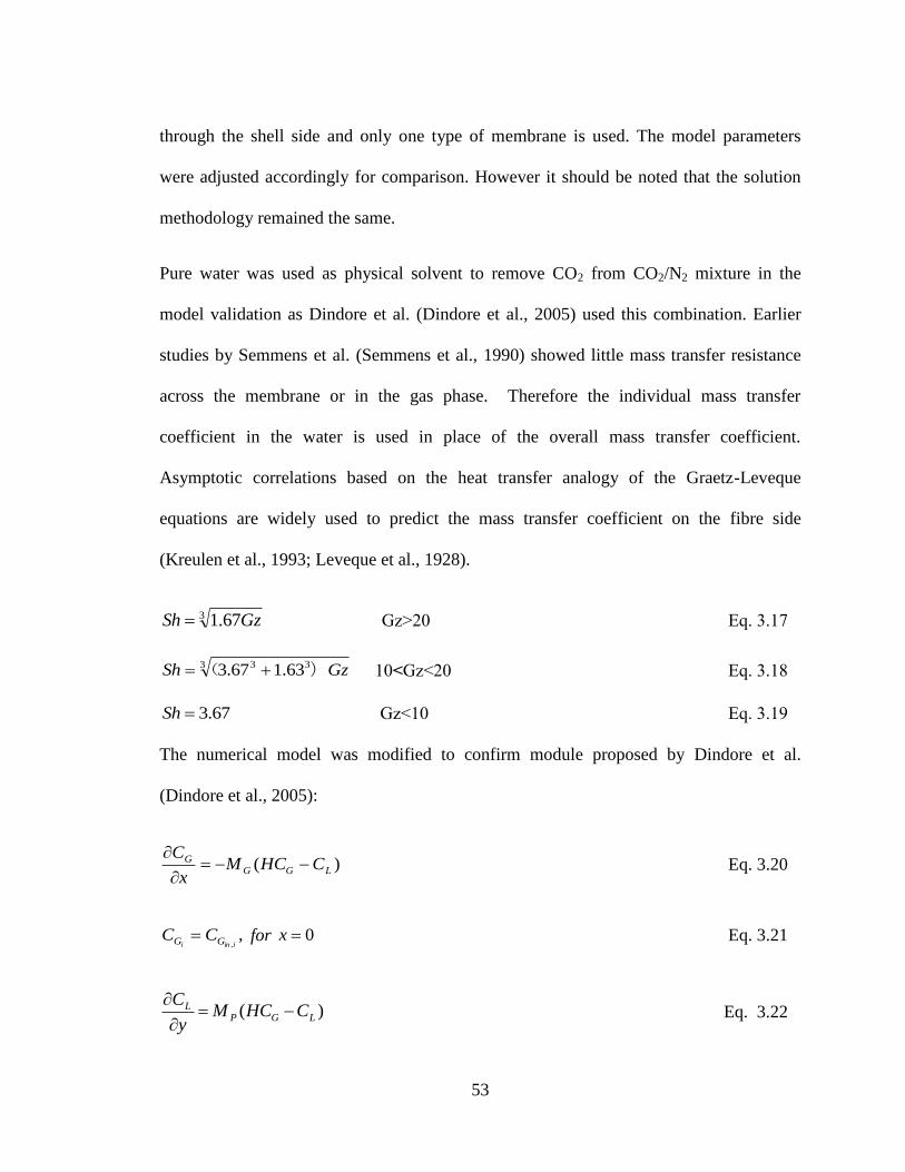
53
through the shell side and only one type of membrane is used. The model parameters
were adjusted accordingly for comparison. However it should be noted that the solution
methodology remained the same.
Pure water was used as physical solvent to remove CO2 from CO2/N2 mixture in the
model validation as Dindore et al. (Dindore et al., 2005) used this combination. Earlier
studies by Semmens et al. (Semmens et al., 1990) showed little mass transfer resistance
across the membrane or in the gas phase. Therefore the individual mass transfer
coefficient in the water is used in place of the overall mass transfer coefficient.
Asymptotic correlations based on the heat transfer analogy of the Graetz-Leveque
equations are widely used to predict the mass transfer coefficient on the fibre side
(Kreulen et al., 1993; Leveque et al., 1928).
Gz>20 Eq. 3.17
10<Gz<20 Eq. 3.18
Gz<10 Eq. 3.19
The numerical model was modified to confirm module proposed by Dindore et al.
(Dindore et al., 2005):
Eq. 3.20
for Eq. 3.21
Eq. 3.22
3 67.1 GzSh
3 33 )63.167.3 GzSh (
67.3Sh
)( LGGG CHCM
x
C
,,iini GG CC 0x
)( LGPL CHCM
y
C
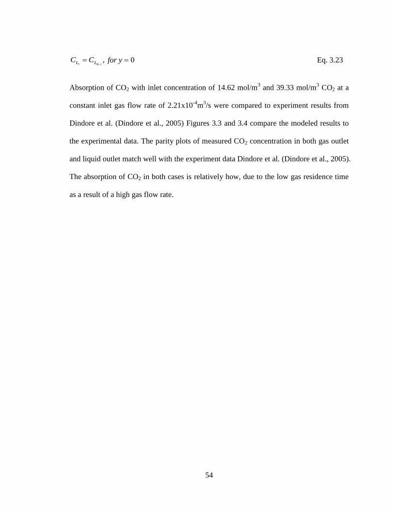
54
for Eq. 3.23
Absorption of CO2 with inlet concentration of 14.62 mol/m3 and 39.33 mol/m
3 CO2 at a
constant inlet gas flow rate of 2.21x10⁻⁴
m3/s were compared to experiment results from
Dindore et al. (Dindore et al., 2005) Figures 3.3 and 3.4 compare the modeled results to
the experimental data. The parity plots of measured CO2 concentration in both gas outlet
and liquid outlet match well with the experiment data Dindore et al. (Dindore et al., 2005).
The absorption of CO2 in both cases is relatively how, due to the low gas residence time
as a result of a high gas flow rate.
,,iini LL CC 0y
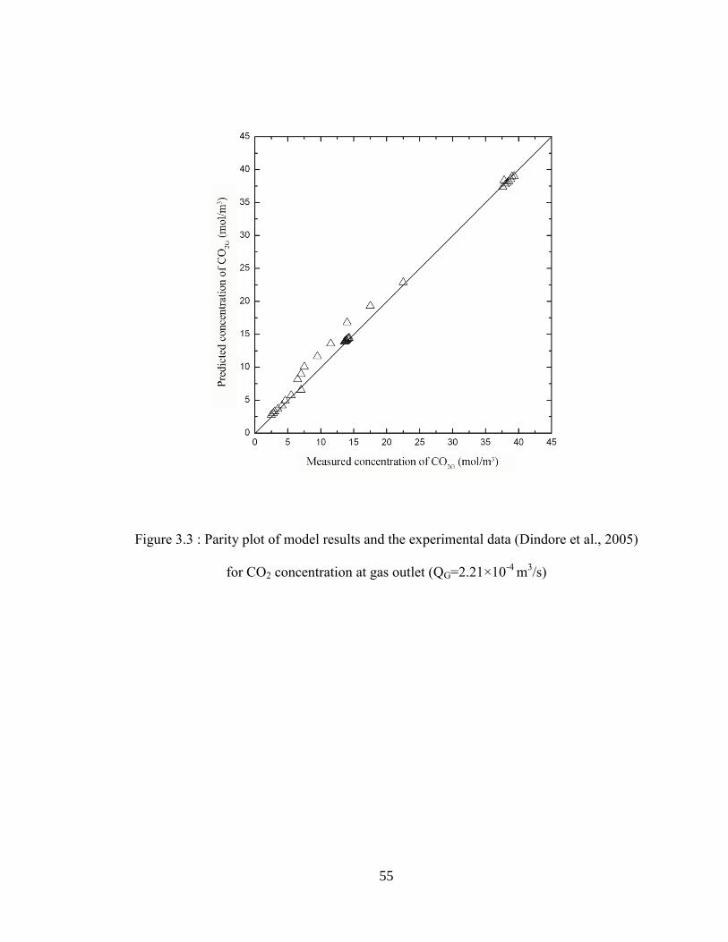
55
Figure 3.3 : Parity plot of model results and the experimental data (Dindore et al., 2005)
for CO2 concentration at gas outlet (QG=2.21×10⁻⁴
m3/s)
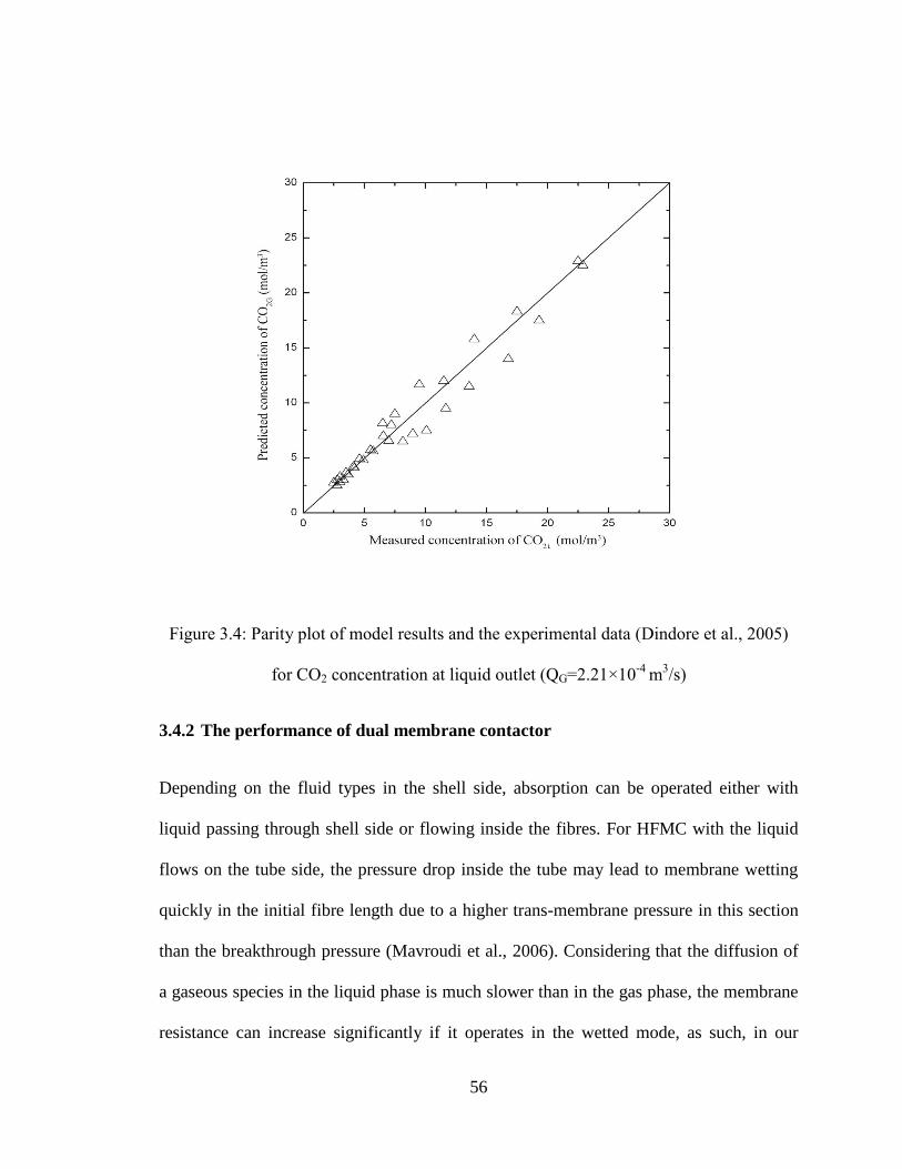
56
Figure 3.4: Parity plot of model results and the experimental data (Dindore et al., 2005)
for CO2 concentration at liquid outlet (QG=2.21×10⁻⁴
m3/s)
3.4.2 The performance of dual membrane contactor
Depending on the fluid types in the shell side, absorption can be operated either with
liquid passing through shell side or flowing inside the fibres. For HFMC with the liquid
flows on the tube side, the pressure drop inside the tube may lead to membrane wetting
quickly in the initial fibre length due to a higher trans-membrane pressure in this section
than the breakthrough pressure (Mavroudi et al., 2006). Considering that the diffusion of
a gaseous species in the liquid phase is much slower than in the gas phase, the membrane
resistance can increase significantly if it operates in the wetted mode, as such, in our

57
module, the liquid flows in the shell side of HFMC. Nonporous membrane fibres are
introduced with low pressure or vacuum inside the fibres, absorption of CO2 from
CO2/CH4 mixture is investigated. Propylene carbonate was selected as the absorbent since
it offers high solubility for CO2. Specification of modules studied in this work and
parameters used in calculation are shown in Table 3.1, modified from experimental data
from other researchers (Dindore et al., 2005).
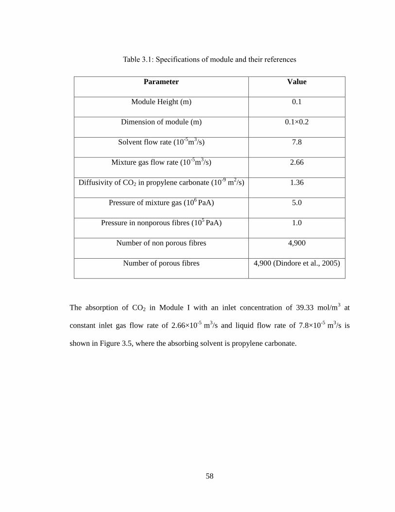
58
Table 3.1: Specifications of module and their references
Parameter Value
Module Height (m) 0.1
Dimension of module (m) 0.1×0.2
Solvent flow rate (10-5
m3/s) 7.8
Mixture gas flow rate (10-5
m3/s) 2.66
Diffusivity of CO2 in propylene carbonate (10-9
m2/s) 1.36
Pressure of mixture gas (106
PaA) 5.0
Pressure in nonporous fibres (105
PaA) 1.0
Number of non porous fibres 4,900
Number of porous fibres 4,900 (Dindore et al., 2005)
The absorption of CO2 in Module I with an inlet concentration of 39.33 mol/m3 at
constant inlet gas flow rate of 2.66×10⁻⁵
m3/s and liquid flow rate of 7.8×10
-5 m
3/s is
shown in Figure 3.5, where the absorbing solvent is propylene carbonate.
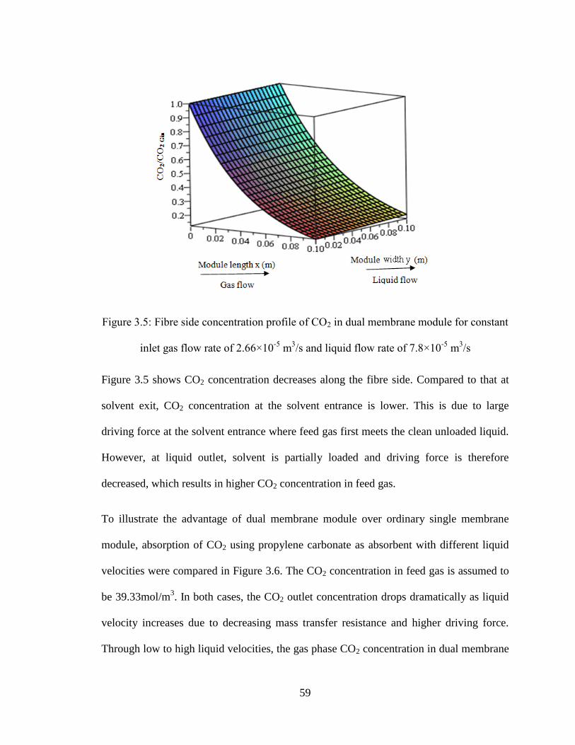
59
Figure 3.5: Fibre side concentration profile of CO2 in dual membrane module for constant
inlet gas flow rate of 2.66×10⁻⁵
m3/s and liquid flow rate of 7.8×10
-5 m
3/s
Figure 3.5 shows CO2 concentration decreases along the fibre side. Compared to that at
solvent exit, CO2 concentration at the solvent entrance is lower. This is due to large
driving force at the solvent entrance where feed gas first meets the clean unloaded liquid.
However, at liquid outlet, solvent is partially loaded and driving force is therefore
decreased, which results in higher CO2 concentration in feed gas.
To illustrate the advantage of dual membrane module over ordinary single membrane
module, absorption of CO2 using propylene carbonate as absorbent with different liquid
velocities were compared in Figure 3.6. The CO2 concentration in feed gas is assumed to
be 39.33mol/m3. In both cases, the CO2 outlet concentration drops dramatically as liquid
velocity increases due to decreasing mass transfer resistance and higher driving force.
Through low to high liquid velocities, the gas phase CO2 concentration in dual membrane

60
module is always lower than that of single membrane module. At liquid velocity of
0.005m/s, CO2 absorption in dual membrane module is much higher than that of single
membrane. This is mainly because the partial regeneration of solvent can maintain the
concentration gradient across the porous membrane. The difference gradually diminishes
as liquid velocity increases. As more liquid passes through the module, more CO2 is
absorbed in less contacting time, which meanwhile minimizes the impact of solvent
regeneration and therefore results in lower CO2 concentration in nonporous fibres.
Additionally, CO2 concentration in liquid phase in dual membrane module is also found
much lower compared to that in single membrane module, which again approves the
regeneration function of nonporous membrane.
Figure 3.6: Absorption of 39.33 mol/m3 CO2 absorption under different liquid velocity for
constant inlet gas flow rate of 2.66×10⁻⁵
m3/s
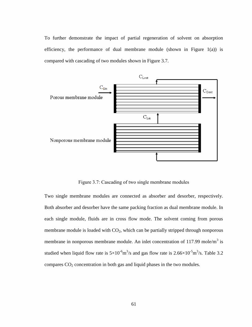
61
To further demonstrate the impact of partial regeneration of solvent on absorption
efficiency, the performance of dual membrane module (shown in Figure 1(a)) is
compared with cascading of two modules shown in Figure 3.7.
Figure 3.7: Cascading of two single membrane modules
Two single membrane modules are connected as absorber and desorber, respectively.
Both absorber and desorber have the same packing fraction as dual membrane module. In
each single module, fluids are in cross flow mode. The solvent coming from porous
membrane module is loaded with CO2, which can be partially stripped through nonporous
membrane in nonporous membrane module. An inlet concentration of 117.99 mole/m3 is
studied when liquid flow rate is 5×10⁻⁶
m3/s and gas flow rate is 2.66×10
-5m
3/s. Table 3.2
compares CO2 concentration in both gas and liquid phases in the two modules.
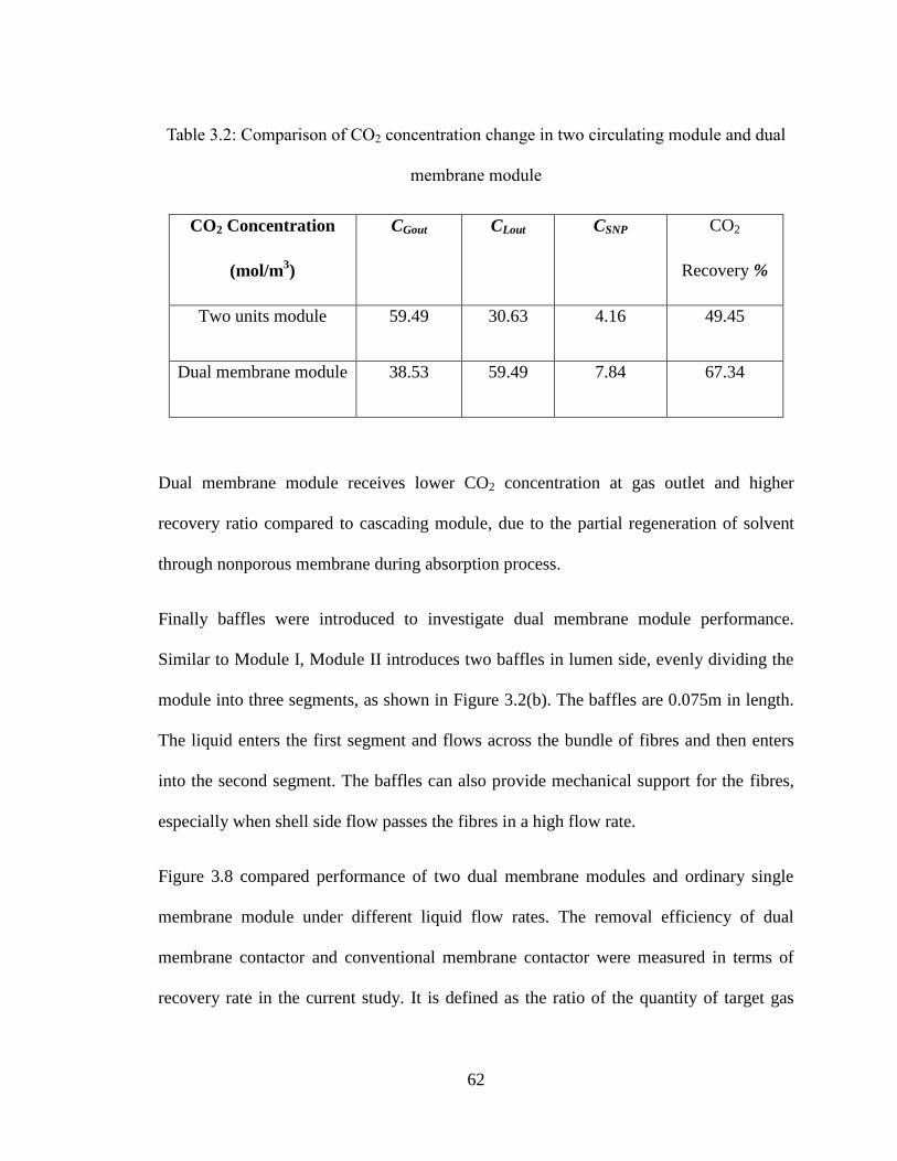
62
Table 3.2: Comparison of CO2 concentration change in two circulating module and dual
membrane module
CO2 Concentration
(mol/m3)
CGout CLout CSNP CO2
Recovery %
Two units module 59.49 30.63 4.16 49.45
Dual membrane module 38.53 59.49 7.84 67.34
Dual membrane module receives lower CO2 concentration at gas outlet and higher
recovery ratio compared to cascading module, due to the partial regeneration of solvent
through nonporous membrane during absorption process.
Finally baffles were introduced to investigate dual membrane module performance.
Similar to Module I, Module II introduces two baffles in lumen side, evenly dividing the
module into three segments, as shown in Figure 3.2(b). The baffles are 0.075m in length.
The liquid enters the first segment and flows across the bundle of fibres and then enters
into the second segment. The baffles can also provide mechanical support for the fibres,
especially when shell side flow passes the fibres in a high flow rate.
Figure 3.8 compared performance of two dual membrane modules and ordinary single
membrane module under different liquid flow rates. The removal efficiency of dual
membrane contactor and conventional membrane contactor were measured in terms of
recovery rate in the current study. It is defined as the ratio of the quantity of target gas
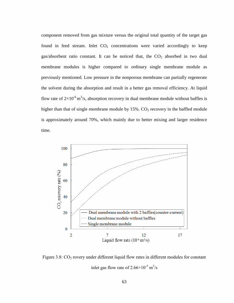
63
component removed from gas mixture versus the original total quantity of the target gas
found in feed stream. Inlet CO2 concentrations were varied accordingly to keep
gas/absorbent ratio constant. It can be noticed that, the CO2 absorbed in two dual
membrane modules is higher compared to ordinary single membrane module as
previously mentioned. Low pressure in the nonporous membrane can partially regenerate
the solvent during the absorption and result in a better gas removal efficiency. At liquid
flow rate of 2×10⁻⁶
m3/s, absorption recovery in dual membrane module without baffles is
higher than that of single membrane module by 15%. CO2 recovery in the baffled module
is approximately around 70%, which mainly due to better mixing and larger residence
time.
Figure 3.8: CO2 rovery under different liquid flow rates in different modules for constant
inlet gas flow rate of 2.66×10⁻⁵
m3/s
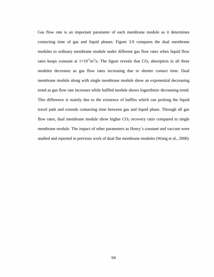
64
Gas flow rate is an important parameter of each membrane module as it determines
contacting time of gas and liquid phases. Figure 3.9 compares the dual membrane
modules to ordinary membrane module under different gas flow rates when liquid flow
rates keeps constant at 1×10⁻⁵
m3/s. The figure reveals that CO2 absorption in all three
modules decreases as gas flow rates increasing due to shorter contact time. Dual
membrane module along with single membrane module show an exponential decreasing
trend as gas flow rate increases while baffled module shows logarithmic decreasing trend.
This difference is mainly due to the existence of baffles which can prolong the liquid
travel path and extends contacting time between gas and liquid phase. Through all gas
flow rates, dual membrane module show higher CO2 recovery ratio compared to single
membrane module. The impact of other parameters as Henry’s constant and vaccum were
studied and reported in previous work of dual flat membrane modules (Wang et al., 2006)
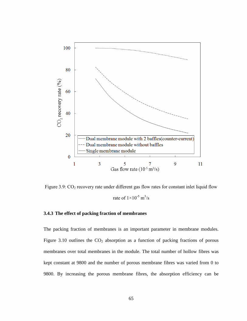
65
Figure 3.9: CO2 recovery rate under different gas flow rates for constant inlet liquid flow
rate of 1×10⁻⁵
m3/s
3.4.3 The effect of packing fraction of membranes
The packing fraction of membranes is an important parameter in membrane modules.
Figure 3.10 outlines the CO2 absorption as a function of packing fractions of porous
membranes over total membranes in the module. The total number of hollow fibres was
kept constant at 9800 and the number of porous membrane fibres was varied from 0 to
9800. By increasing the porous membrane fibres, the absorption efficiency can be
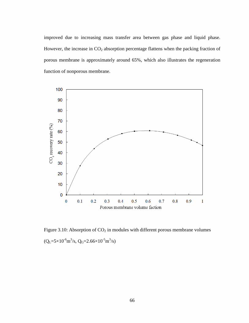
66
improved due to increasing mass transfer area between gas phase and liquid phase.
However, the increase in CO2 absorption percentage flattens when the packing fraction of
porous membrane is approximately around 65%, which also illustrates the regeneration
function of nonporous membrane.
Figure 3.10: Absorption of CO2 in modules with different porous membrane volumes
(QL=5×10⁻⁶
m3/s, QG=2.66×10
-5m
3/s)

67
3.5 Conclusion
Two configurations of hollow fibre membrane absorption-stripping systems were
proposed with their performance were numerically studied. Based on the analysis
presented in this chapter, it can be concluded that the nonporous membranes in the dual
HFMC can partially regenerate the solvent during the absorption and result in a better
overall gas removal efficiency. Consequently, it can reduce the required solvent flow rate
to achieve the same CO2 removal level. In addition, the baffles can increase the mass
transfer by providing better mixing and longer residence time of the liquid phase. Of
course, this must be balanced against the size and cost of the contactor. To predict
removal efficiency of proposed modules, a numerical model based on mass balance was
also developed in this study and it showed good agreement with previous experiment al
results (Dindore et al., 2005).
All analysis and results shown in this chapter are based on mathematical models. The
supporting experiments are carried out with experimental results presented in the
following chapters. The liquid velocity was assumed to be constant through the module,
which is not the case in practice. Therefore, fluid dynamics of liquid flow in shell side
and its impacts on mass transfer coefficients is also included in the following chapters.
68
References
Zhang, Q., Cussler, E.L., Microporous hollow fibres for gas absorption II. mass transfer
across the membrane, Journal of Membrane Science, 23 (1985), 333-345
Baker, R.W., Roman, I.C., Lonsdale, H.K., Liquid membranes for the production of
oxygen-enriched air I. Introduction and passive liquid membranes, Journal of
Membrane Science,31 (1987), 15-29
Bessarabov, D.G., Teplyakov, V.V. Beckman, I.N., Selective membrane valve for ternary
gas mixture separation: model of mass transfer and experimental test, Industrial &
Engineering Chemistry Research, 32 (1993), 2017-2022
Coelhoso, M., Cardoso, M.M., Viegas, R.M.C., Crespo, J.P.S.G., Transport mechanism
and modeling in liquid membrane contactors, Separation and Purification
Technology 19(2000), 183-197
Dindore, V.Y., Brilman, D.W.F., Versteeg, G. F., Hollow fibre membrane contactor as a
gas–liquid model contactor, Chemical Engineering Science, 60 (2005), 467-479
Dindore, V.Y., Brilman, G. F.,Versteeg, D. W. F., Modelling of cross-flow membrane
contactors: physical mass transfer processes, Journal of Membrane Science, 251
(2005), 209-222
Dindore, V.Y., Versteeg, G.F., Gas-liquid mass transfer in a cross-flow hollow fibre
module: Analytical model and experimental validation, International Journal of Heat
Mass Transfer 48 (2005), 3352-3362
Falk-Pedersen, O., Dannström, H., Separation of carbon dioxide from offshore gas
turbine exhaust, Energy Conversion Management, 38 (1997), S81-S86
69
Hoffman, A., Theoretical solution for cross-flow heat exchanger, Heat Mass Transfer
36(2000), 127-133
Hughes, R.D., Mahoney J.A., Steigelmann, E.F., Olefin separation by facilitated
transport membranes, Recent Developments in Separation Science, CRC Press,
Cleveland, 1986
Jansen, A.E., Klaassen, R., Feron, P.H.M., Hanemaaijer, J.H., Meulen, B.P., Membrane
gas absorption processes in environmental applications in Membrane Processes in
Separation and Purification, Kluwer Academic Publishers, Dordrecht, 1994
Johnson, B.M., Baker, R.W., Matson, S.L., Smith, K.L., Roman, I.C., Tuttle, M.E.,
Lonsdale, H.K., Liquid membranes for the production of oxygen-enriched air II.
Facilitated-transport membranes, Journal of Membrane Science, 31 (1987), 31-67
Kimura, S.G., Walment, G.F., Fuel gas purification with perm-selective membranes.
Separation Science Technology, 15(1980), 1115-1133
Kosaraju, P., Kowali, A. S., Korikov, A., Sirkar, K., Hollow fibre membrane contactor
based CO2 absorption-stripping using novel solvents and membranes, 44(5)
(2005), 1250-1258
Kreulen, H., Versteeg, G.F., Smolders, C.A., Swaaij W.P.M.V, Determination of mass
transfer rates in wetted and non-wetted microporous membranes, Chem. Eng. Sci.,
48(11) (1993), 2093-2102
Kreulen, H., Smolders, C.A., Versteeg, G.F., Swaaij, W.P.M.V., Microporous hollow-
fibre membrane modules as gas–liquid contactors: 1. Physical mass transfer
processes—a specific application: mass transfer in highly viscous liquids. Journal of
Membrane Science, 78(1993) (3), 197–216
70
Kreulen, H., Smolders, C.A., Versteeg, G.F.,Swaaij, W.P.M.V., Selective removal of H2S
from sour gas with microporous membranes, Part II. A liquid membrane of water
free tertiary amines, Journal of Membrane Science, 82 (1993) 185-197
Leveque, J., Les lois de la transmission de chaleur par convection. Annls. Mines, Paris
(12) (1928), 201
Majumdar, S., Guha, A. K., Sirkar, K. K., A new liquid membrane technique for gas
separation, AIChE Journal, 34(1988), 1135-1145
Mataon, S.L., Lopez, J., Quinn, J.A., Separation of Gases with Synthetic Membranes,
Chemical Engineering Science, 38(1983), 503-524
Mavroudi, M., Kaldis, S.P., Sakellaropoulos, G.P., Mass and momentum transfer in
hollow fibre blood oxygenators, Journal of Membrane Science, 272 (2006), 103–115
Poddar, T.K., Majumdar S., Sirkar, K.K., Membrane-based Absorption of VOCs from a
Gas Stream, AIChE Journal, 42(11) (1996), 3267-3282
Semmens, M.J., D.M. Foster and E.L. Cussler, Ammonia removal from water using
microporous hollow fibres, Journal of Membrane Science, 51 (1990), 127-140
Teramoto, M., Matsuyama, H., Yamashiro, T., Katayama, Y., Separation of ethylene
from ethane by supported liquid membranes contained silver nitrate as a carrier,
Journal of Chemical Engineering of Japan., 19(5) (1986), 419-424
Teramoto, M., Matsuyama, H., Yamashiro, T., Okamoto, S., Separation of ethylene from
ethane by a flowing liquid membrane using silver nitrate as a carrier, Journal of
Membrane Science, 45(1989), 115-136
Wang, K. L., Cussler, E.L., Baffled membrane modules made with hollow fibre fabric, J.
Membr. Sci. 85(1993), 265-278
71
Wang, S.Y., Hawboldt, K., Abdi, M.A., Novel dual-membrane gas-liquid contactors:
modeling and concept analysis, Industrial & Engineering Chemistry Research 45
(2006), 782-789
Wickramasinghe, S.R., Garcia, J.D., Han, B., Mass and momentum transfer in hollow
fibre blood oxygenators, Journal of Membrane Science, 208 (2002), 247–256
Wickramasinghe, S.R., Semmens, M. J., Cussler, E.L., Mass transfer in various hollow
fibre geometries. Journal of Membrane Science, 69(1992), 235-250
Zhang, Q., Cussler, E.L., Microporous hollow fibres for gas absorption II. mass transfer
across the membrane, Journal of Membrane Science, 23 (1985), 333-345
Zhang, Q., Cussler, E.L., Microporous hollow fibres for gas absorption I. mass transfer in
the liquid, Journal of Membrane Science, 23 (1985), 321-332
72
Chapter 4
EXPERIMENTAL STUDY OF GAS ABSORPTION USING
DUAL MEMBRANE CONTACTOR
——————————————————————
This chapter is based on and modified based on the following paper
Cai, J.J., Hawboldt, K., Majid, A., Improving gas absorption efficiency using a novel
dual membrane contactor. Journal of membrane science, 510(2016), 249-258
73
By introducing “dual membrane concept” into the design of membrane contactor for
offshore gas treatment, higher gas absorption can be achieved in a more compact
membrane module with smaller footprint. The performance of the proposed dual
membrane module for gas absorption has been numerically studied in Chapter 3. Our
focus in this chapter is on the assessment and optimization of the absorption performance
of dual membrane contactors through experimental approach. Section 4.1 reviews the
experimental study of dual membrane module used for various applications. Section 4.2
presents details of a lab scale dual membrane contactor containing two types of
membranes (polypropylene membrane and silicone rubber membrane) which is designed
and constructed for gas absorption process. In Section 4.3, the module performance was
evaluated based on permeation flux experiments for CO2 absorption. The experimental
results were compared with the predictions from a numerical model developed in our
previous studies. Furthermore, the mass transfer resistance in the fabricated module was
investigated using resistance-in-series model. An empirical correlation was developed to
describe mass transfer coefficient under different operational conditions.
4.1 Background
As mentioned previously in Chapter 3.1, one option to minimize equipment footprint is to
use two types of membranes in the same module where one membrane type functions in
absorption and the other in solvent regeneration or a dual-membrane module (DMM).
The dual membrane concept was first proposed and tested for H2/CO2 separation which
allowed bulk CO2 to be removed simultaneously with bulk H2 recovery (Ohno et al.,

74
1977). Two types of membranes with different permeability for specific gases were
included in the same module. A novel dual membrane reactor was designed with one
tubular porous ceramic membrane as a reactant distributor and a second tubular porous
ceramic membrane as a membrane separator (Chen et al., 2011). The experimental results
showed that the dual membrane system can achieve ultrafine catalysts separation and
product selectivity enhancement simultaneously. A few researchers have also explored
the potential of dual membrane system for different applications used for reactors (Chen
et al., 2014; Chen et al., 2016; Godinia et al., 2013). However, there are limited studies on
improving gas absorption performance using a dual membrane system. Obuskovic et al.
(Obuskovic et al., 1998) investigated the potential of dual membrane systems for VOC
(volatile organic compounds) removal. Two sets of hollow fibres membranes were used
in the same module, the gas to be treated was fed to the fibre side of microporous
polypropylene membrane while a second set of silicone coated fibres were used as a
desorber. The shell side was filled with a non-circulating liquid absorbent. Since the
liquid phase in shell side was in a non-flowing mode, the system was operated in a semi-
continuous mode, which required long operating time to achieve high treatment
efficiencies. A parallel flow membrane system was proposed as a more compact design
(Wang et al., 2006). In this system gas absorption and solvent regeneration were
simulated with two types of flat sheet membrane: porous polypropylene membrane and
nonporous silicone rubber membrane. The simulation showed good potential in terms of
overall size reduction and gas removal efficiency. This study was further extended by
proposing a cross flow dual membrane module which was composed of hollow fibre
75
membrane as hollow fibre membrane offers a larger interfacial area per volume than flat
sheet membrane (Cai et al., 2012). The performance of this dual membrane module was
evaluated through modelling approach. The result showed that gas removal efficiency of
the dual membrane system was 38% higher than conventional system that uses two units
in series to perform gas absorption and stripping separately. This is mainly because the
simultaneous regeneration of solvent along with absorption process can help the driving
force responsible for mass transfer maintain at a high level (Cai et al., 2012). Nonetheless,
all these results were based on numerical modeling and needs to be further confirmed
through experiments.
Therefore, the objective of this chapter is to develop a dual membrane system and
conduct experiments to investigate its performance. A dual membrane system is
fabricated that combines the adsorption and solvent regeneration into one unit, further
decreasing the equipment footprint. The following issues will be addressed in this chapter:
1. Fabrication of a dual hollow fibre membrane contactor module;
2. Evaluation of the module performance for simultaneous absorption and stripping;
3. Development of an empirical mass transfer correlation for the system;
4. Validation of the mathematical model;
5. Optimization of the absorption process by studying the effect of operation
conditions, assisted with simulation results.
76
In these experiments, CO2 was removed using physical absorption as the solvents used for
physical absorption generally are more compatible with porous membranes (Dindore et
al., 2004).
4.2 Experiments
4.2.1 Fabrication and assembly of lab scale dual membrane contactor
The membrane core contains two type of fibre membranes, polypropylene (PP) fibre (for
gas flows into system) and silicone rubber tubing (for partial regeneration of solvent). PP
membranes have sufficiently low surface energy, are inexpensive, and commercially
available in small diameters (Dindore et al., 2004). Silicone rubber is attractive in
degassing of a liquid as there is no issue related to membrane wetting, therefore, the
pressure on permeate side can be arbitrarily chosen. Ito et al. validated the feasibility to
strip dissolved oxygen from water using silicone hollow fibre membranes (Ito et al.,
1998). However, this material has not been applied to other gases such as CO2 or H2S.
Compared to oxygen, the permeability of CO2 through silicone rubber fibres is much
higher. The porous PP fibre (Q3/2 membrane) purchased from Membrana GmbH has an
outside diameter of 1,000 µm and inside diameter of 600 µm and a maximum pore size of
0.64 µm. Silicone rubber tubing from Dow company has outside diameter of 900 µm and
inside diameter of 500 µm. The fibres were first trimmed into the same length and then
potted into supporting plates at both ends (Shown in Figure 4.1). The supporting plate
was made of polyvinyl chloride (PVC) and drilled through with 1.02 mm holes, arranged
in a staggered pattern (Show in Figure.4.1 (a)). The use of supporting plate assures the

77
uniformity distribution of membrane in membrane core. Porous and nonporous fibres
were then woven through the supporting plates and layered alternately. Liquid epoxy
resin was applied afterwards to fix fibres to supporting plates. In this process, care must
be taken to avoid damaging the membrane surface as porous membrane fibres tend to
break easily. The finished membrane core was then built into a PVC housing in which the
transparent PVC made it possible to observe the liquid flow in shell side. The shell
housing was purposely made in a rectangular geometry instead of cylindrical geometry.
As for the cylindrical module, the cross-sectional area for flow varies along the path,
causing the average velocity to alternately increase and decrease. In contrast, the flow
area is constant in modules with rectangular designs, which can simplify the modelling.
The impact of module geometries is discussed with more details in the following chapters.
As it is shown in Figure.4.1 (b), separate inlets and outlets were designed for gas
absorption and stripping in the module, respectively.
(a) (b)
Figure 4.1(a): Schematic drawing of membrane core and arrangement of dual hollow
fibre membranes in lab scale module; (b) Schematic drawing of dual membrane contactor
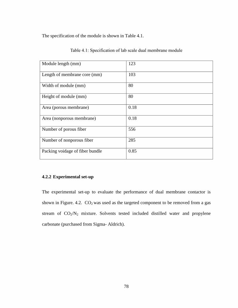
78
The specification of the module is shown in Table 4.1.
Table 4.1: Specification of lab scale dual membrane module
Module length (mm) 123
Length of membrane core (mm) 103
Width of module (mm) 80
Height of module (mm) 80
Area (porous membrane) 0.18
Area (nonporous membrane) 0.18
Number of porous fiber 556
Number of nonporous fiber 285
Packing voidage of fiber bundle 0.85
4.2.2 Experimental set-up
The experimental set-up to evaluate the performance of dual membrane contactor is
shown in Figure. 4.2. CO2 was used as the targeted component to be removed from a gas
stream of CO2/N2 mixture. Solvents tested included distilled water and propylene
carbonate (purchased from Sigma- Aldrich).
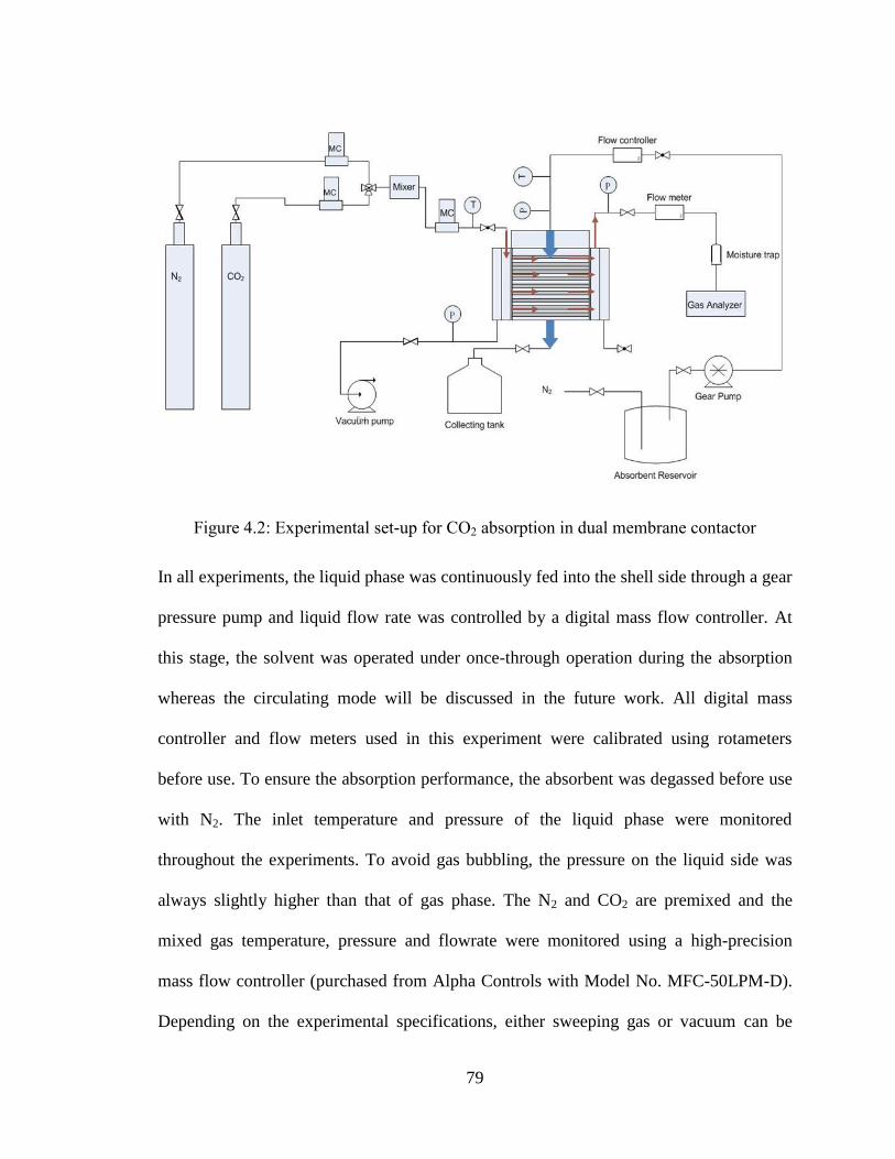
79
Figure 4.2: Experimental set-up for CO2 absorption in dual membrane contactor
In all experiments, the liquid phase was continuously fed into the shell side through a gear
pressure pump and liquid flow rate was controlled by a digital mass flow controller. At
this stage, the solvent was operated under once-through operation during the absorption
whereas the circulating mode will be discussed in the future work. All digital mass
controller and flow meters used in this experiment were calibrated using rotameters
before use. To ensure the absorption performance, the absorbent was degassed before use
with N2. The inlet temperature and pressure of the liquid phase were monitored
throughout the experiments. To avoid gas bubbling, the pressure on the liquid side was
always slightly higher than that of gas phase. The N2 and CO2 are premixed and the
mixed gas temperature, pressure and flowrate were monitored using a high-precision
mass flow controller (purchased from Alpha Controls with Model No. MFC-50LPM-D).
Depending on the experimental specifications, either sweeping gas or vacuum can be

80
used for gas stripping in the nonporous fibre. Figure 4.2 is an example of operation with
vacuum being applied. N2 was used at a constant flow rate of 5LPM. In the case where
the vacuum was applied, a vacuum pump was connected to the nonporous fibre side. The
pressure was measured using a PM930SD pressure indicator (Cole-Parmer) and
controlled using a high precision needle valve. Membrane wetting may occur during
operation when pressure in the gas flow is insufficient therefore the mixed gas was
introduced into the fibre side before liquid was introduced into the shell side. The
pressure difference between the two phases was monitored in all experiments. The CO2
was measured through portable Oxybaby®6.0 CO2 gas analyzer at gas inlet and outlet.
The average CO2 concentration in liquid was estimated via overall mass balance. The
details of experimental conditions are given in Table 4.2.
Table 4.2: Experimental conditions for test conducted in the research presented in this
chapter
CO2% CO2
(mol/m3)
Operation mode
(In nonporous
fibres)
Sweeping Gas
(flow rate
4L/min)
Vacuum
(kpa below gauge)
5 2.04 No degassing - -
5 2.04 Sweeping gas N2 -
5 2.04 vacuum - 2-30
2.5 1.02 Sweeping gas N2 -
30 12.26 Sweeping gas N2 -
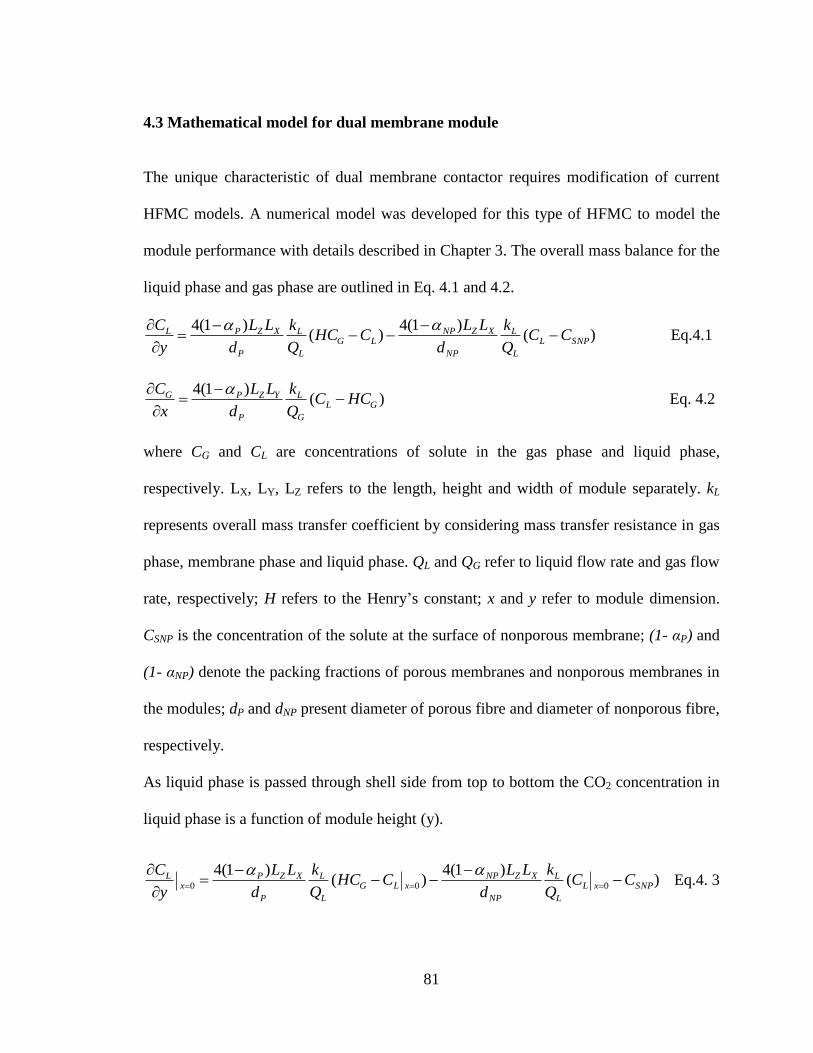
81
4.3 Mathematical model for dual membrane module
The unique characteristic of dual membrane contactor requires modification of current
HFMC models. A numerical model was developed for this type of HFMC to model the
module performance with details described in Chapter 3. The overall mass balance for the
liquid phase and gas phase are outlined in Eq. 4.1 and 4.2.
Eq.4.1
Eq. 4.2
where CG and CL are concentrations of solute in the gas phase and liquid phase,
respectively. LX, LY, LZ refers to the length, height and width of module separately. kL
represents overall mass transfer coefficient by considering mass transfer resistance in gas
phase, membrane phase and liquid phase. QL and QG refer to liquid flow rate and gas flow
rate, respectively; H refers to the Henry’s constant; x and y refer to module dimension.
CSNP is the concentration of the solute at the surface of nonporous membrane; (1- αP) and
(1- αNP) denote the packing fractions of porous membranes and nonporous membranes in
the modules; dP and dNP present diameter of porous fibre and diameter of nonporous fibre,
respectively.
As liquid phase is passed through shell side from top to bottom the CO2 concentration in
liquid phase is a function of module height (y).
Eq.4. 3
)()1(4
)()1(4
SNPL
L
L
NP
XZNPLG
L
L
P
XZPL CCQ
k
d
LLCHC
Q
k
d
LL
y
C
)()1(4
GL
G
L
P
YZPG HCCQ
k
d
LL
x
C
)()1(4
)()1(4
000 SNPxL
L
L
NP
XZNPxLG
L
L
P
XZPx
L CCQ
k
d
LLCHC
Q
k
d
LL
y
C

82
The second boundary condition can be defined as follows as no CO2 is present in the
liquid phase at liquid inlet.
y =0 at liquid inlet
Similarly in the gas phase, CO2 concentration only changes with the module length (x).
At the liquid entrance where y is equal to zero,
Eq. 4.4
At gas inlet
, at x=0 Eq. 4.5
By solving the above two partial differential equations simultaneously the CO2
concentration in both liquid phase and gas phase can be predicted at any position in the
module.
4.4 Results
4.4.1 Correlation for mass transfer coefficient in shell side
Compared to modules containing only porous or nonporous membrane, mass transfer in
dual membrane module is more complex. For the purpose of module design and operation
optimization, it is critical to generate a correlation to predict mass transfer coefficient for
different operational conditions. For modules operated with liquid in shell side flowing
across beds of gas filled hollow fibres, mass transfer coefficient mainly depends on liquid
LiL CC
)()1(4
00
yGL
G
L
P
YZPy
G HCCQ
k
d
LL
x
C
GiG CC
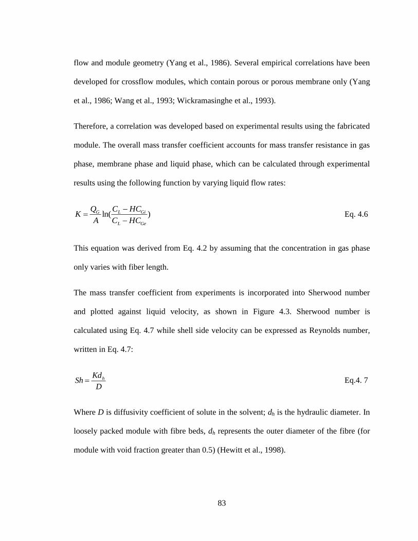
83
flow and module geometry (Yang et al., 1986). Several empirical correlations have been
developed for crossflow modules, which contain porous or porous membrane only (Yang
et al., 1986; Wang et al., 1993; Wickramasinghe et al., 1993).
Therefore, a correlation was developed based on experimental results using the fabricated
module. The overall mass transfer coefficient accounts for mass transfer resistance in gas
phase, membrane phase and liquid phase, which can be calculated through experimental
results using the following function by varying liquid flow rates:
Eq. 4.6
This equation was derived from Eq. 4.2 by assuming that the concentration in gas phase
only varies with fiber length.
The mass transfer coefficient from experiments is incorporated into Sherwood number
and plotted against liquid velocity, as shown in Figure 4.3. Sherwood number is
calculated using Eq. 4.7 while shell side velocity can be expressed as Reynolds number,
written in Eq. 4.7:
Eq.4. 7
Where D is diffusivity coefficient of solute in the solvent; dh is the hydraulic diameter. In
loosely packed module with fibre beds, dh represents the outer diameter of the fibre (for
module with void fraction greater than 0.5) (Hewitt et al., 1998).
)ln(GeL
GiLG
HCC
HCC
A
QK
D
KdSh h

84
Eq.4. 8
Where Re is Reynolds number, ν stands for kinematic viscosity of solvent and u
represents effective velocity passing through fibre bundles, which can be calculated
through dividing superficial velocity by void fraction (Hewitt et al., 1998).
The experiment was conducted using the fabricated module for CO2 absorption where
water is used as solvent. The feed gas contained 5% CO2 and was passed through the tube
side at a constant flow rate of 1.63 L/min. A sweep gas of N2 flowed through the
nonporous fibres at a flowrate of 4 L/min. The CO2 concentration in the gas outlet was
read off through gas analyzer while CO2 concentration in liquid phase was determined by
titration using 0.4M sodium hydroxide. Phenolphthalein was used as the indicator for the
titration. The mass transfer coefficient, Sherwood number (Sh) and Reynolds number
were then calculated accordingly using the known data of feed flow and module
dimensions. Results for the calculated Reynolds number and Sherwood number are
summarized in Table 4.3.
Table 4.3: Experimentally data and calculated Reynolds number and Sherwood number
Water flow rate QL(×10-6
m3/s) Reynolds number Sherwood number
1.08 0.15 3.52
2.00 0.32 5.15
2.9 0.42 5.9
3.91 0.63 7.27
v
udh Re

85
6.66 1.08 9.5
9.3 1.52 11.34
10 1.63 11.75
15 2.44 14.46
19.1 3.12 16.3
A commonly used form of empirical correlation for the Sh is shown in Eq.4.9 (Gabelman
et al., 1999):
Sh = αReβSc0.33
Eq. 4.9
Where α and β are constants determined by fitting experimental results. The Schmidt (Sc)
number is calculated by dividing the viscosity of the solvent by the diffusion coefficient
(of solute in solvent). Based on our experimental data the correlation reduces to:
Eq. 4.10
As it is shown in Figure 4.3, this correlation relates with the experimental results very
well. Figure 4.3 compares the proposed correlation to another two correlations developed
for porous membrane contactor and nonporous membrane contactor, respectively. These
two correlations were both applicable for the range of Reynolds number examined in the
present study. As presented, Sherwood number based on the current study falls in the
range between two other correlations found in literature (Cote et al., 1989; Yang et al.,
1993) confirming that these equations are not accurate and the new correlation is required
for this dual membrane system.
33.05226.0Re78.0 ScSh
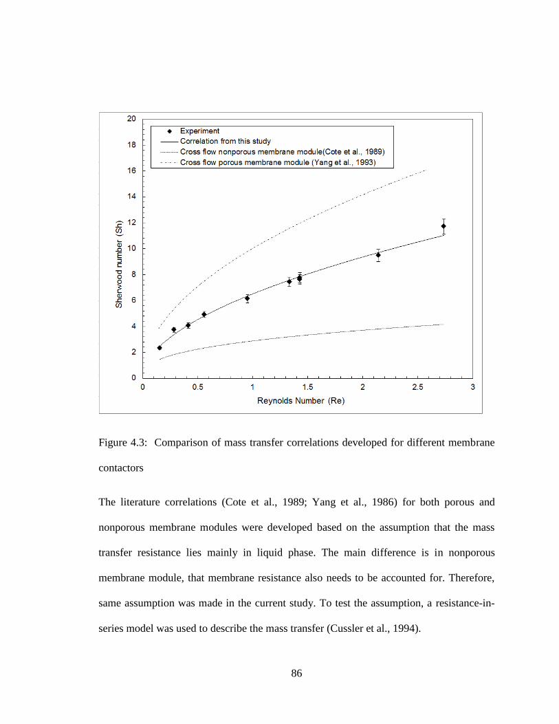
86
Figure 4.3: Comparison of mass transfer correlations developed for different membrane
contactors
The literature correlations (Cote et al., 1989; Yang et al., 1986) for both porous and
nonporous membrane modules were developed based on the assumption that the mass
transfer resistance lies mainly in liquid phase. The main difference is in nonporous
membrane module, that membrane resistance also needs to be accounted for. Therefore,
same assumption was made in the current study. To test the assumption, a resistance-in-
series model was used to describe the mass transfer (Cussler et al., 1994).

87
Figure 4.4 Mass transfer regions and resistance-in-series in non-wetted dual membrane
contactor
Figure 4.4 depicts the mass transport of the interested gas for non-wetted mode of
operation of dual membrane contactors, i.e., diffusion from the bulk gas through the
membrane pores, dissolution in the liquid absorbent and stripping of dissolved
contaminant from solvent. The mass transfer resistance (RTotal) of the above mentioned
mass transfer process is mainly contributed by four parts: gas phase, liquid phase, porous
membrane and nonporous membrane, as described in Eq. 4.11:
NMlPMgTotal RRRRR Eq. 4.11
where Rg, RPM, Rl, RNM represent mass transfer resistances from gas phase, porous
membrane, liquid phase and nonporous membrane, respectively.
It can also be converted to a function of mass transfer coefficient, as shown in Eq. 4.12.

88
lnmmg kkHkHkK
11111
Eq.4.12
Where K and H refers to the overall mass transfer coefficient and Henry’s constant
separately; kg, km, kl, knm are mass transfer coefficient through gas phase, porous
membrane, liquid phase and nonporous membrane respectively. The mass transfer
resistance through nonporous membrane can be calculated in the following equation
(Bessarabov et al., 1996; Atchariyawut et al., 2008):
HP
l
k
NP
m
1 Eq. 4.13
Where P is the polymer permeability and l is the thickness of the nonporous membrane
layer.
The Wilson plot (Atchariyawut et al., 2008), which was originally used to analyse heat
transfer resistance has been used in membrane mass transfer resistance in gas–liquid
membrane contacting processes. As shown in Eq. 4.10, the mass transfer coefficient can
be expressed as a function of velocity:
Eq. 4.14
The plot 1/K versus 1/v0.5226
give a straight line as shown in Figure 4.5, where the fitting
function has a R squared value greater than 0.99. The intercept corresponds to when 1/KL
is zero and represents the resistance from nonporous membrane. Therefore, the
interception of the plot represents the resistance in nonporous membrane. Based on our
5226.0
11
vK
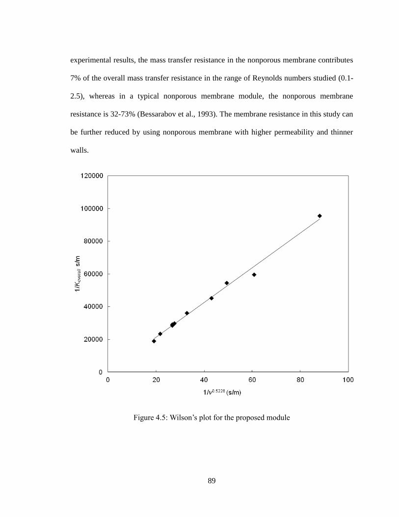
89
experimental results, the mass transfer resistance in the nonporous membrane contributes
7% of the overall mass transfer resistance in the range of Reynolds numbers studied (0.1-
2.5), whereas in a typical nonporous membrane module, the nonporous membrane
resistance is 32-73% (Bessarabov et al., 1993). The membrane resistance in this study can
be further reduced by using nonporous membrane with higher permeability and thinner
walls.
Figure 4.5: Wilson’s plot for the proposed module

90
The relationship between Sherwood number and Reynolds number is a strong function of
shell side flow and module geometry, which however should be independent of solvent
selections and operation mode on the permeate side. To further confirm this assumption,
experiments were carried out in this study by replacing water with propylene carbonate as
solvent. Meanwhile, low vacuum was applied on the permeated side instead of sweeping
gas with the vacuum pressure was maintained below 2kPa. The Sherwood number
derived based on experimental results were compared against those calculated from the
proposed correlation in the parity plot shown in Figure 4.6. It demonstrates that the
proposed correlation can be used to predict the fibre side mass transfer coefficient in case
of organic solvents. Moreover, it confirms that the Sherwood number indeed depends
mainly on the module geometry of membrane contactor and independent of operation
condition on permeation side.
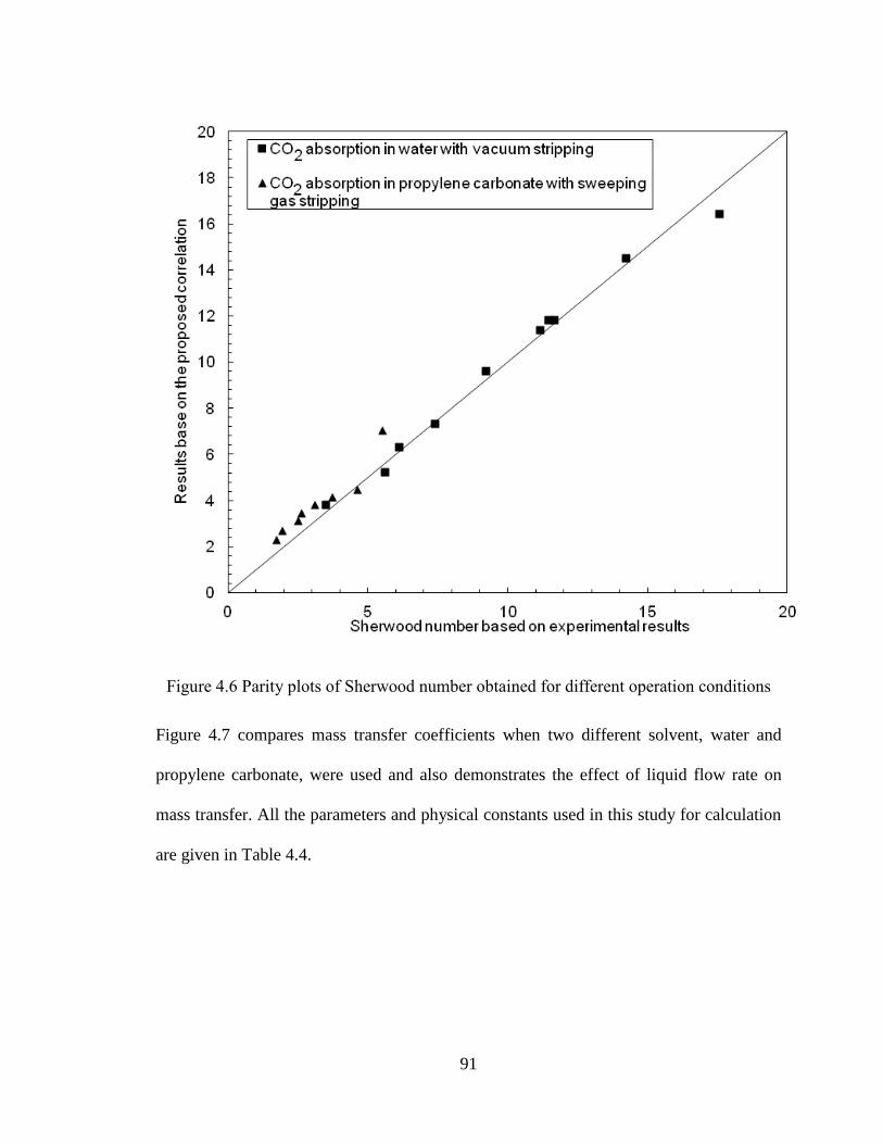
91
Figure 4.6 Parity plots of Sherwood number obtained for different operation conditions
Figure 4.7 compares mass transfer coefficients when two different solvent, water and
propylene carbonate, were used and also demonstrates the effect of liquid flow rate on
mass transfer. All the parameters and physical constants used in this study for calculation
are given in Table 4.4.
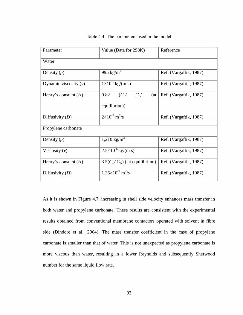
92
Table 4.4: The parameters used in the model
Parameter Value (Data for 298K) Reference
Water
Density (ρ) 995 kg/m3 Ref. (Vargaftik, 1987)
Dynamic viscosity (ν) 1×10⁻⁶
kg/(m s) Ref. (Vargaftik, 1987)
Henry’s constant (H) 0.82 (CL/ CG) (at
equilibrium)
Ref. (Vargaftik, 1987)
Diffusivity (D) 2×10⁻⁹
m2/s Ref. (Vargaftik, 1987)
Propylene carbonate
Density (ρ) 1,210 kg/m3 Ref. (Vargaftik, 1987)
Viscosity (ν) 2.5×10⁻⁶
kg/(m s) Ref. (Vargaftik, 1987)
Henry’s constant (H) 3.5(CL/ CG) ( at equilibrium) Ref. (Vargaftik, 1987)
Diffusivity (D) 1.35×10⁻⁹
m2/s Ref. (Vargaftik, 1987)
As it is shown in Figure 4.7, increasing in shell side velocity enhances mass transfer in
both water and propylene carbonate. These results are consistent with the experimental
results obtained from conventional membrane contactors operated with solvent in fibre
side (Dindore et al., 2004). The mass transfer coefficient in the case of propylene
carbonate is smaller than that of water. This is not unexpected as propylene carbonate is
more viscous than water, resulting in a lower Reynolds and subsequently Sherwood
number for the same liquid flow rate.
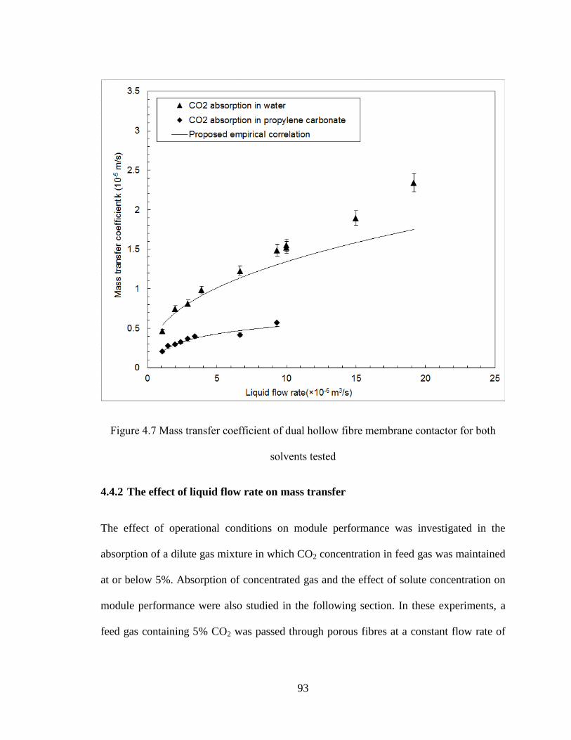
93
Figure 4.7 Mass transfer coefficient of dual hollow fibre membrane contactor for both
solvents tested
4.4.2 The effect of liquid flow rate on mass transfer
The effect of operational conditions on module performance was investigated in the
absorption of a dilute gas mixture in which CO2 concentration in feed gas was maintained
at or below 5%. Absorption of concentrated gas and the effect of solute concentration on
module performance were also studied in the following section. In these experiments, a
feed gas containing 5% CO2 was passed through porous fibres at a constant flow rate of
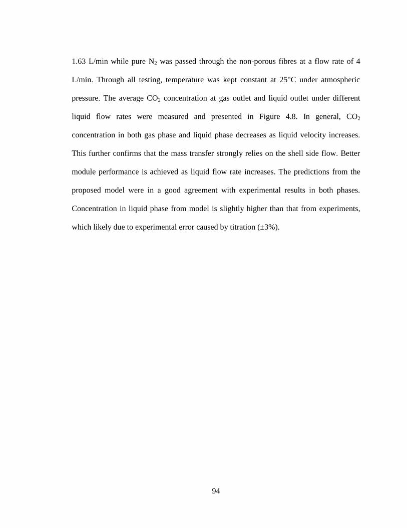
94
1.63 L/min while pure N2 was passed through the non-porous fibres at a flow rate of 4
L/min. Through all testing, temperature was kept constant at 25°C under atmospheric
pressure. The average CO2 concentration at gas outlet and liquid outlet under different
liquid flow rates were measured and presented in Figure 4.8. In general, CO2
concentration in both gas phase and liquid phase decreases as liquid velocity increases.
This further confirms that the mass transfer strongly relies on the shell side flow. Better
module performance is achieved as liquid flow rate increases. The predictions from the
proposed model were in a good agreement with experimental results in both phases.
Concentration in liquid phase from model is slightly higher than that from experiments,
which likely due to experimental error caused by titration (±3%).
95
Figure 4.8 : CO2 (5%) absorption in dual membrane module with sweeping gas degassing
Parallel tests were also carried out with a vacuum pressured supplied in nonporous fibres.
The vacuum pressure on permeated side was maintained slightly lower than atmospheric
pressure (5 kPa). Model predictions and experimental results mirrored the results with the
sweep gas and therefore are not included here. The impact of vacuum pressure on the
tests results will be discussed later in this paper. Absorption flux is an indicator of
process efficiency, i.e., high flux correlates to high efficiency. Absorption flux was
estimated by making an overall mass balance on the contactor:
96
A
QCQCJ GeGeGiGi
average
)( Eq. 4.15
Where J is the molar flux (mol/m2 s); A (m
2) effective interfacial area; CGi and CGe are the
volumetric concentration of CO2 in the feed and outlet streams, respectively. QGi and QGe
(m3/s) are volumetric flow rate measured at gas inlet and outlet. Figure 4.9 illustrates the
effect of liquid flow rate on absorption flux under different operationalconditions. The
absorption of dilute feed gas containing 5% CO2 was firstly investigated, in which water
was used as absorbent. In one set of experiments, the module was operated in a no solvent
regeneration mode, that is no sweep gas or vacuum was applied to the non-porous fibres.
Comparing to the absorption flux with gas stripping on permeate side, the impact of
simultaneous gas stripping along with absorption placed on overall absorption flux can be
determined. The absorption flux is well predicted by the numerical modelling. In general,
absorption flux is enhanced as liquid flow rate increases. With a sweep gas in nonporous
fibres, the absorption flux is found higher, compared to the non-regeneration mode. This
is not unexpected due to the higher mass transfer coefficients resulted from high shell side
flow. Meanwhile, the presence of sweep gas/vacuum further enlarges the differential
partial pressure across nonporous membrane. As a result, there is enhanced permeation of
the dissolved CO2 in the liquid phase to permeate side through the nonporous membrane.
It is worth mentioning that since the experiment was carried out at a relatively high gas
flow rate of 1.63L/min, the overall removal efficiency is below 15%. The impact of gas
flow rates on removal efficiency was further examined in the following sections.
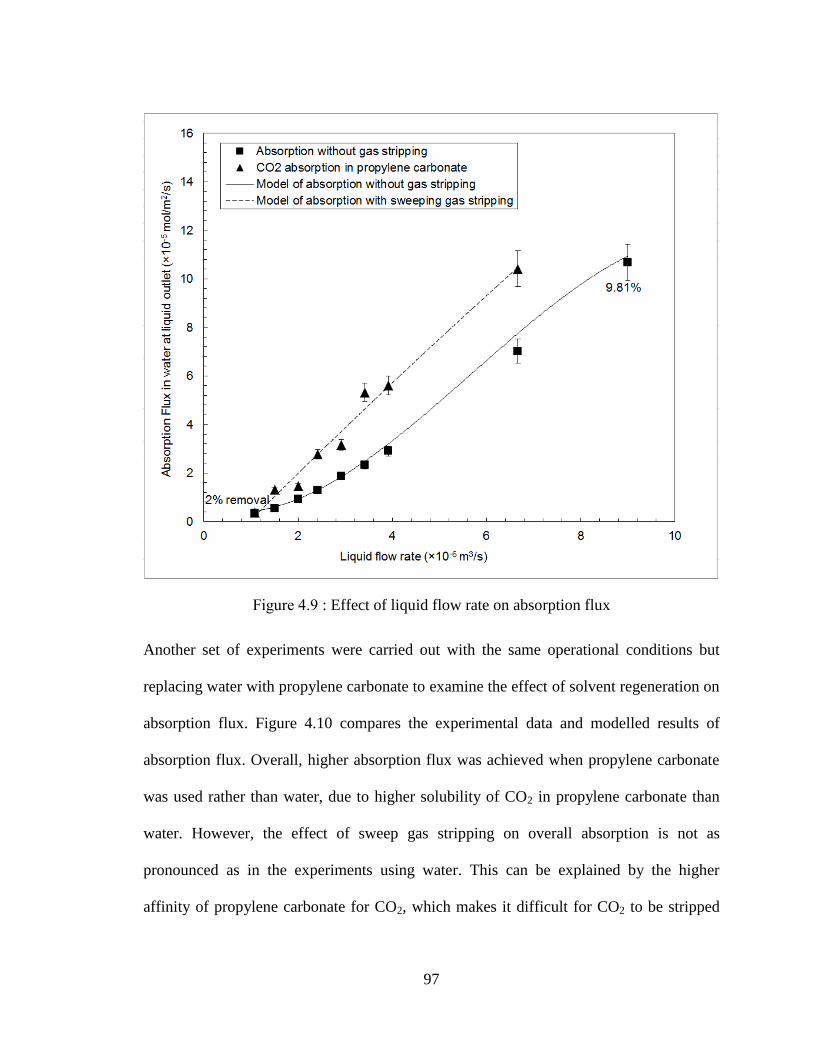
97
Figure 4.9 : Effect of liquid flow rate on absorption flux
Another set of experiments were carried out with the same operational conditions but
replacing water with propylene carbonate to examine the effect of solvent regeneration on
absorption flux. Figure 4.10 compares the experimental data and modelled results of
absorption flux. Overall, higher absorption flux was achieved when propylene carbonate
was used rather than water, due to higher solubility of CO2 in propylene carbonate than
water. However, the effect of sweep gas stripping on overall absorption is not as
pronounced as in the experiments using water. This can be explained by the higher
affinity of propylene carbonate for CO2, which makes it difficult for CO2 to be stripped
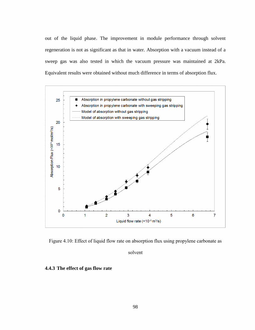
98
out of the liquid phase. The improvement in module performance through solvent
regeneration is not as significant as that in water. Absorption with a vacuum instead of a
sweep gas was also tested in which the vacuum pressure was maintained at 2kPa.
Equivalent results were obtained without much difference in terms of absorption flux.
Figure 4.10: Effect of liquid flow rate on absorption flux using propylene carbonate as
solvent
4.4.3 The effect of gas flow rate
99
The effect of gas flow rate on absorption flux is summarized in Figure 4.11. The
experiments were carried out using water as absorbent at a constant flow rate of 2×10-
6m
3/s. A sweep gas of N2 was passed through nonporous fibres at a flow rate of 4L/min.
For comparison purposes, parallel experiments were also conducted without sweep gas.
Gas flow rates were varied from 3.7×10⁻⁶
m3/s to 23.3×10
-6m
3/s. The CO2 concentration at
the gas outlet decreased with increasing gas flow rate while the absorption flux almost
stays constant. This further confirms that for physical absorption in liquid-gas membrane
contactor, the transfer resistance lies mainly in liquid phase. The sweep gas improved flux
by approximately 50%. The lower gas flow rates show better removal from the gas due to
the longer gas residence time. However, it is worth mentioning that sweep gas degassing
plays a more important role at higher gas flow rates. At a relatively low gas flow rate of
3.7×10⁻⁶
m3/s, 26.9% CO2 was removed with the sweep gas compared to 19.3% removal
rate without sweep gas, which improves the overall absorption efficiency by 39%. At a
higher gas flow rate of 2.3×10⁻⁵
m3/s, total removal efficiency decreases in both cases due
to reduced gas residence time in the module. By stripping the dissolved gas with sweep
gas, the removal efficiency increased from 2.46% to 4.4%, improved by 78%. It implies
that simultaneous degassing during absorption has a great potential in the case that
operating flow rate is high.

100
Figure 4.11: Effect of gas flow rate on absorption flux using water as solvent
4.4.4 The effect of solute concentration
When experiments were carried out at high gas flow rate using very low levels of CO2 in
the inlet gas stream, the removal rate is relatively low and therefore the volumetric gas
flow rate is relatively constant. However, gas streams with high levels of CO2 and high
removal rates, the effect of a change in the volumetric flow rate of the gas stream needs to
be considered. In the current study, the change in volumetric flow rate can be described
using the following equation:
101
Eq.4. 16
Where QGi is the volumetric flow rate of feed gas at inlet; CGi is the concentration at gas
inlet while CG is the CO2 concentration any position of module; P, R, and T stand for
pressure (Pascal), gas constant (8.314m3 Pa/ K/ mol) and temperature (K), respectively.
By combining Eq. 4.16 and Eq.4.2, CO2 concentration at gas outlet was calculated in
model.
Experiments were conducted varying inlet CO2 concentration from 2.5%, 5% and 30%
under a relatively low gas flow rate of 3.7×10⁻⁶
m3/s. The liquid flow rate was kept
constant at 0.175 L/min. A constant flow of 4L/min N2 was passed through nonporous
fibres on the permeate side. The absorption flux from experiments is compared with the
model prediction in Figure 4.12. As CO2 concentration increases, absorption flux
dramatically increases from 1.6×10⁻⁵
to 42×10-5
mol/m2s, due to the high driving force of
concentration differences. The removal efficiency is also higher for the absorption of a
more concentrated feed gas. As solute concentration increases, the change in gas flow rate
caused by loss of solute becomes more obvious. Several models have been proposed to
describe mass transfer in cross flow module, such as the heat transfer analogy (Dindore et
al., 2005), however these models ignore the change in volumetric gas flow rate. As
demonstrated in the figure, when this factor is not accounted, the predicted absorption
flux (shown in dash line) is lower than experimental results and tends to under-predict
module performance.
G
GiGiGi
G
CP
RT
QCP
RTQ
Q
1
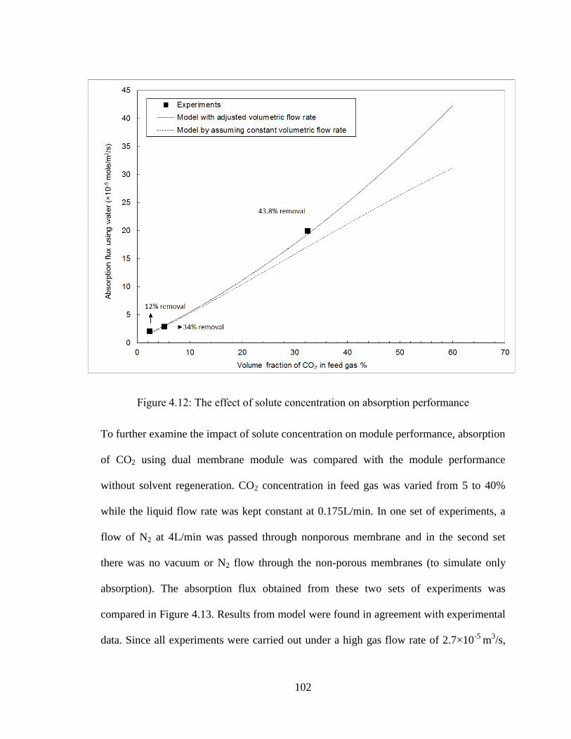
102
Figure 4.12: The effect of solute concentration on absorption performance
To further examine the impact of solute concentration on module performance, absorption
of CO2 using dual membrane module was compared with the module performance
without solvent regeneration. CO2 concentration in feed gas was varied from 5 to 40%
while the liquid flow rate was kept constant at 0.175L/min. In one set of experiments, a
flow of N2 at 4L/min was passed through nonporous membrane and in the second set
there was no vacuum or N2 flow through the non-porous membranes (to simulate only
absorption). The absorption flux obtained from these two sets of experiments was
compared in Figure 4.13. Results from model were found in agreement with experimental
data. Since all experiments were carried out under a high gas flow rate of 2.7×10⁻⁵
m3/s,
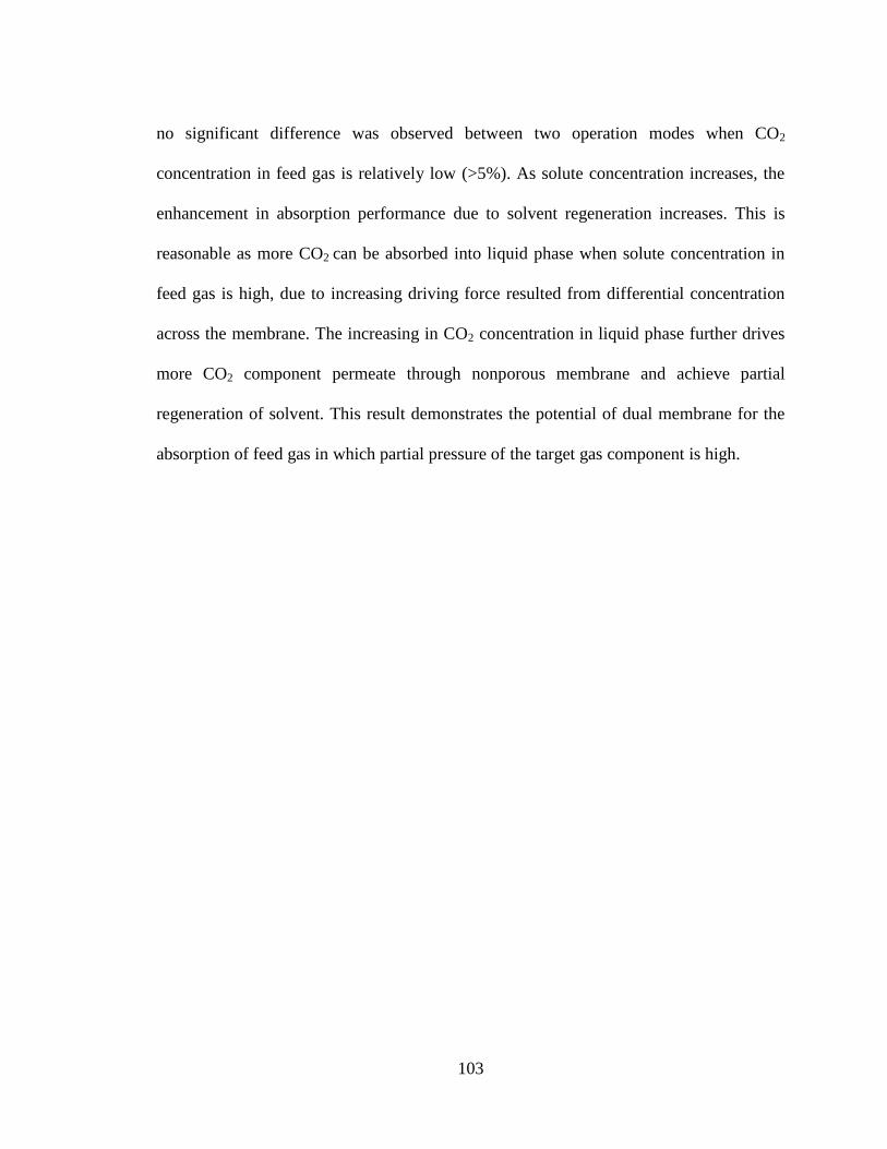
103
no significant difference was observed between two operation modes when CO2
concentration in feed gas is relatively low (>5%). As solute concentration increases, the
enhancement in absorption performance due to solvent regeneration increases. This is
reasonable as more CO2 can be absorbed into liquid phase when solute concentration in
feed gas is high, due to increasing driving force resulted from differential concentration
across the membrane. The increasing in CO2 concentration in liquid phase further drives
more CO2 component permeate through nonporous membrane and achieve partial
regeneration of solvent. This result demonstrates the potential of dual membrane for the
absorption of feed gas in which partial pressure of the target gas component is high.
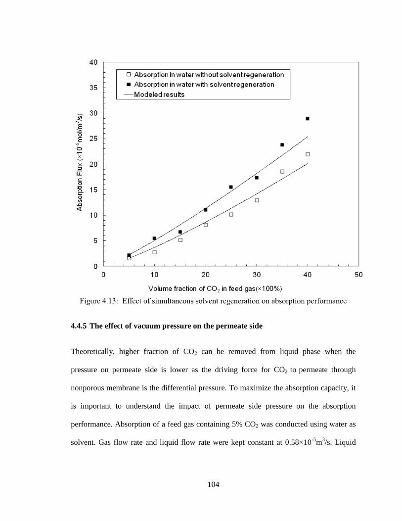
104
Figure 4.13: Effect of simultaneous solvent regeneration on absorption performance
4.4.5 The effect of vacuum pressure on the permeate side
Theoretically, higher fraction of CO2 can be removed from liquid phase when the
pressure on permeate side is lower as the driving force for CO2 to permeate through
nonporous membrane is the differential pressure. To maximize the absorption capacity, it
is important to understand the impact of permeate side pressure on the absorption
performance. Absorption of a feed gas containing 5% CO2 was conducted using water as
solvent. Gas flow rate and liquid flow rate were kept constant at 0.58×10⁻⁵
m3/s. Liquid
105
flow rate was constant at 2×10⁻⁶
m3/s. On the permeate side, the vacuum pressure was
varied from 2 to 67 kPa.
Figure 4.14: The effect of permeate side pressure to overall absorption performance
As shown in Figure 4.14, the good agreement between model and experimental results
further confirms the advantage of introducing degassing along with absorption process.
The CO2 concentration in both gas phase and liquid phase decreases as higher vacuum
was applied to the nonporous membranes. However, the increase in removal is small.
That is, as the vacuum pressure is increased to 20kPa from 2kPa by ten times, CO2
106
removal efficiency is only improved from 20% to 23.6%. The selection of appropriate
pressure needs to account for the balance between energy consumption for maintaining
high vacuum and removal efficiency.
4.4.6 The effect of area ratio of porous and nonporous membrane
In this type of contactor, a dual membrane, careful analysis of the ratio of one type of
membrane to another is critical. For example, by increasing the porous fibres present in
shell side, absorption of CO2 into liquid phase can be enhanced but possibly at the
expense of degassing due to the reduced nonporous membrane area. Given the model has
been validated in the experiments; a simulation was performed where the ratio of non-
porous to porous membranes was varied. Total absorption flux is compared in modules
with different ratio of porous membrane area over nonporous membrane area where the
total membrane area and module packing fraction were kept constant. The enhancement
in absorption is also examined by comparing dual membrane module performance to the
module with porous membrane only. Model results are summarized in Figure 4.15.
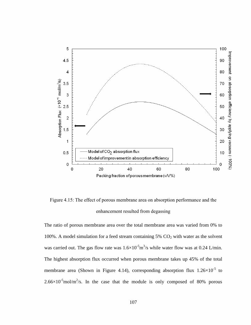
107
Figure 4.15: The effect of porous membrane area on absorption performance and the
enhancement resulted from degassing
The ratio of porous membrane area over the total membrane area was varied from 0% to
100%. A model simulation for a feed stream containing 5% CO2 with water as the solvent
was carried out. The gas flow rate was 1.6×10⁻⁵
m3/s while water flow was at 0.24 L/min.
The highest absorption flux occurred when porous membrane takes up 45% of the total
membrane area (Shown in Figure 4.14), corresponding absorption flux 1.26×10⁻⁵
to
2.66×10⁻⁵
mol/m2/s. In the case that the module is only composed of 80% porous
108
membrane, the removal efficiency drops to 37%. This validates our initial work present in
the previous chapter in which better removal was achieved when porous and non-porous
membranes were present. However the simulation also shows that there is an optimal
ratio of fibres. Compared to modules operated without sweeping gas/vacuum in
nonporous fibres, the enhancement in absorption efficiency is the most obvious when
vacuum degassing is applied and nonporous membrane takes up to 50% of overall
membrane area. This indicates that the most ideal packing ratio for porous membrane
over nonporous membrane is 0.45 to 0.5This range may need to be adjusted according to
the membrane material used for absorption and solvent regeneration.
4.4 Conclusion
In this work, an experimental study of a lab scale dual membrane module was carried out
to investigate its performance over conventional membrane contactor and validate the
numerical model developed to simulate the system. The concept of dual membrane
module was first proposed by Wang et al. (Wang et al., 2006), which however has never
been testified through experiment studies. In this study, a lab scale membrane contactor
composed of polypropylene porous fibres and nonporous silicone rubber tubing was built
and its performance was demonstrated through removal of CO2 out from N2/CO2 mixed
gas. Empirical correlations tailored for the proposed module was developed and the
correlation was validated through experiments results. The mass transfer resistance in the
designed module was also investigated using resistance in series model. The experimental
results show that the resistance mainly comes from liquid film while the membrane
resistance also contributes to 7% of the total resistance. Based on the results, mass

109
transfer coefficient was quantified through correlation for the proposed module and the
experiments were then further extended to CO2 absorption along with simultaneous
degassing through nonporous membrane. Two operations were alternatively applied for
degassing in nonporous membrane namely a sweep gas and a vacuum pressure. The
experimental results were found in a good agreement with numerical modelling
developed in previous work. In addition, it was found that by stripping dissolved CO2 out
from liquid phase through nonporous membrane, absorption on the side of porous
membrane can be effectively improved. The enhancement was especially significant for
the application running at high gas flow rate. High liquid flow rate and vacuum pressure
are the favored conditions for the contactor to achieve maximum performance.
Furthermore, the enhancement in absorption efficiency attributed by degassing was found
most significant in module with 50% packing fraction of porous membrane area. This
conclusion can be used for further optimization of the module. Furthermore, the proposed
model is also modified in this work for absorption of concentrated gas, by accounting for
the change in volumetric flow rate caused by the loss of solute. The results showed that
modified model provides a more accurate prediction of module performance, particularly
when CO2% is greater than 5% in feed gas. The results were validated through
experiments and it also demonstrated that higher absorption efficiency is received as
solute concentration increases. It should be noted that the removal efficiencies are likely
lower compared to a scaled up version of the system. This is due to the constraints
introduced by the small scale module (e.g. ensuring good sealing of fibres to module, etc.),
dimensions of the module (based on this work we will modify the length, height, width
ratios), etc. This work served to both validate our model and to test various operational

110
conditions. In subsequent work presented in the following chapters, we will present the
model with confidence for design optimization.
111
Reference
Bessarabov, D.G., Jacobs, E.P., Sanderson, R.D., Beckman, I.N., Use of nonporous
polymeric flat-sheet gas-separation membranes in a membrane-liquid contactor:
experimental studies, Journal of Membrane Science, 113 (1996), 275-284
Bessarabov, D.G., Teplyakov, V.V., Beckman, I.N., Selective membrane valve for
ternary gas mixture separation: model of mass transfer and experimental test,
Industrial & Engineering Chemistry Research, 32 (1993), 2017-2022
Cai, J.J., Hawboldt, K., Abdi, M.A., Contaminant removal from natural gas using dual
hollow fibre membrane contactors, Journal of Membrane Science, 397-398 (2012), 9-
16
Chen, B., Ruan, X., Jiang, X., Xiao, W., He, G., Dual-membrane module and its optimal
flow pattern for H2/CO2 separation, Industrial & Engineering Chemistry
Research, 55 (4) (2016), 1064-1075
Chen, R., Mao, H., Zhang, X., Xing, W., Fan, Y., A dual-membrane airlift reactor for
cyclohexanone ammoximation over titanium silicalite, Industrial & Engineering
Chemistry Research, 53 (15) (2014),6372-6379
Cote, P., Bersillon, J.L., Huyard, A., Bubble-free aeration using membranes: Mass
transfer analysis, Journal of membrane science 47 (1989), 91-106
Dindore, V.Y., Brilman, D. W. F., Geuzebroek, F.H., Versteeg, G.F., Membrane-solvent
112
selection for CO2 removal using membrane gas-liquid contactors, Separation
Purification Technology,40 (2004), 133-145
Dindore, V.Y., Brilman, G. F.,Versteeg, D. W. F., Modelling of cross-flow membrane
contactors: physical mass transfer processes, Journal of Membrane Science, 251
(2005), 209-222
Dindore, V.Y., Brilmanb, D.W.F., Feronc, P.H.M., Versteega, G.F., CO2 absorption at
elevated pressures using a hollow fibre membrane contactor, Journal of Membrane
Science, 235(1-2) (2004), 99-109
Gabelman, A., Hwang, S., Hollow fibre membrane contactors, Journal of Membrane
Science, 159 (1999), 61-106
Godinia, H.R., Xiao, S.M., Kima, Görkeb, O., Songa, S., Woznya, G., Dual-membrane
reactor for methane oxidative coupling and dry methane reforming: Reactor
integration and process intensification, Chemical Engineering and Processing:
Process Intensification, (74) (2013),153-64
Hewitt, T.J., Hattler, B.G., Federspiel, W.J., A mathematical model of gas exchange in an
intravenous membrane oxygenator, Annals of Biomedical Engineering, 26 (1998),
166-178
Ito, A., Yamagiwa, K., Tamura, M., Furusawa, M., Removal of dissolved oxygen using
non-porous hollow-fibre membranes, Journal of Membrane Science, 145 (1) (1998),

113
111-117
Obuskovic, G., Poddar, T. K., Sirkar, K.K., Flow swing membrane absorption-
permeation, Industrial & Engineering Chemistry Research 37 (1) (1998), 212-220
Ohno, M., Ozaki, O., Sato, H., Kimura, S., Miyauchi, T., Radioactive rare-gas
separation using a separation cell with 2 kinds of membrane differing in gas
permeability tendency. Journal of Nuclear Science Technology,14 (8) (1977), 589-
602
S.Atchariyawut, R. Jiraratananon and R.Wong, Mass transfer study and modeling of gas–
liquid membrane contacting process by multistage cascade model for CO2
absorption, 63(1) (2008) 15-22
Sirkar, K.K., Other new membrane processes, Membrane Handbook, Chapman and Hall,
New York, 1992, 885-899
Vargaftik, N. B., Handbook of Physical Properties of Liquids and Gases: Pure Substances
and Mixtures, Hemisphere Publishing Corporation, 1987
Wang, K.L., Cussler, E.L., Baffled membrane modules made with hollow fibre fabric,
Journal of Membrane Science 85(1993), 265-278
Wang, S.Y., Hawboldt, K., Abdi, M.A., Novel dual-membrane gas-liquid contactors:
modeling and concept analysis, Industrial & Engineering Chemistry Research 45
(2006), 782-789
114
Wickramasinghe, S. R., Semmens, M. J., Cussler, E. L., Hollow fibre modules made with
hollow fibre fabric, Journal of Membrane Science, 84(1) (1993),1-14
Yang, M., Cussler, E.L., Designing hollow fibre contactors, AIChE Journal, 32 (11)
(1986), 1910-1916

115
Chapter 5
ANALYSIS OF THE EFFECT OF MOUDLE DESIGN ON GAS
ABSORPTION IN CROSS-FLOW HOLLOW FIBER
MEMBRANE CONTACTORS VIA COMPUTATIONAL FLUID
DYNAMICS (CFD) ANALYSIS
This chapter is based on and modified based on the following paper
Cai, J.J., Hawboldt, K., Abdi, M.A., Analysis of the effect of module design on gas
absorption in cross flow hollow membrane contactors via Computational Fluid Dynamics
(CFD) analysis. Journal of membrane science, 520 (2016) 415-424
116
The performance of cross flow hollow membrane contactors for gas absorption
applications is greatly influenced by module characteristics. In Chapter 3 and Chapter 4,
the performance of a lab scale dual membrane module with specific design has been
investigated through numerical and experimental approach. The module design factors
are not included in the scope. This chapter focuses on the module design and its effect on
performance enhancement using computational fluid dynamics (CFD) analysis. This
chapter is organized as follows: Section 5.1 provides background information on the
module design of membrane contactors; In section 5.2, a CFD simulation of a lab scale
cross hollow fibre membrane contactor is developed to estimate shell-side flow and
overall mass transfer performance; In section 5.3, the CFD model is validated with
experimental data from the lab scale module for CO2 absorption. The validated model
was then used to investigate the geometric effect of module design on the shell-side flow
and consequent absorption performance. A few design factors were examined in section
5.4 such as the shell configuration, inlet geometry, header shape, fibre bed height and
packing density. This work shows that a properly designed CFD simulation can be used
as a useful tool to optimize module design for cross flow membrane contactors and
improve absorption performance.
117
5.1 Background
As mentioned previously in Section 2.4.3, cross flow hollow fiber membrane modules
offer higher mass transfer coefficient and lower shell-side pressure drop than parallel flow
modules (Dindore et al., 2005).This could be attributed to the continuous splitting and
remixing of shell-side fluid in cross flow modules, which results in more turbulence and
reduced shell-side channelling. Thus far, several cross flow modules have been developed
and studied for gas absorption applications whereas most of these studies focus more on
the development of membrane materials and absorption process whereas less attention
has been paid on the module design and fabrication (Yang et al., 1986; Dindore et al.,
2005; Zhang et al., 2013).
Wichramasinghe et al. (Wichramasinghe et al., 1992) experimentally studied oxygen
absorption in cross flow HFMCs with various geometries. The highest efficiency was
achieved in modules operated with solvent in the shell-side versus the tube side. The
overall mass transfer performance of modules with liquid phase in shell-side is strongly
influenced by module design and shell geometry. This is due to the fact that in gas-liquid
contacting systems, the mass transfer resistance mainly lies in liquid boundary layer. As a
result, shell-side flow plays a critical role in determining overall mass transfer
performance. For modules operated with liquid solvent flowing through the shell-side, the
overall mass transfer coefficient is a strong function of shell-side flow behavior which in
turn is determined by shell geometries. In contrast to lumen side flow which can be well
described using heat transfer analogy (Skelland, 1974), shell-side flow is more
complicated to correlate and scarce information is available for predicting shell-side flow
118
patterns and mass transfer characteristics (Dindore et al., 2005). Moreover, limited work
has been done to investigate the effect of module design on shell-side flow and
consequent mass transfer of cross flow modules used for gas absorption. Some
researchers have derived a few empirical equations to correlate shell-side flow with mass
transfer performance for cross flow modules with various geometries (Yang et al., 1993;
Bhaumik et al., 1998). It was found from these studies that the shell-side mass transfer is
determined by several factors and their combinations, such as the flow regime, flow
distribution, hydraulic shell diameter and effective length of the module, entrance effects,
fibre dispersion, and packing density (Yang et al., 2013). Thus far, very few of these
factors have been studied with respect to their impacts on shell-side hydrodynamics and
module performance (Yang et al., 1986; Dindore et al., 2005; Yang et al., 2013). Dindore
et al. (Dindore et al., 2005) studied shell-side mixing and mass transfer in a rectangular
cross flow module using residence time distribution (RTD) approach. They concluded
that the shell-side velocity is the key factor determining shell-side mixing and dispersion
rate. In addition to shell-side velocity, shell-side flow distribution is another important
factor affecting module performance (Zheng et al., 2003). The modules with uneven shell
flow distribution performed poorly compared to modules with a more uniform flow
distribution in shell-side (Yang et al., 2013; Yang et al., 2014; Zheng et al., 2003). In
most of these studies, the uneven flow distribution was resulted from irregular fibre
arrangement. The effect of flow distribution into the shell regions of fibre bundles
through external ports and manifolds has received less attention (Mat et al., 2014). The
structure-induced flow maldistribution was found to have a detrimental impact on module
performance when the module is operated with gas phase in shell-side (Zhang et al.,

119
2013). Its impact on modules with liquid in shell-side however has never been reported.
Moreover, the combination effect of shell side flow distribution and shell-side flow
dynamics on module performance also remains unclear.
Computational fluid dynamics (CFD) modeling has been widely adopted to simulate and
analyze fluid dynamic behavior in membrane contactors (Gage et al., 2002; Catapano et
al., 2001; Mazaheri et al., 2006; Fill et al., 2006). The challenge in using CFD for
membrane contactors is the membrane module can be composed of thousands of fibres,
resulting in long computational times and convergence problems. An alternative approach
is to model the fibre bundle as porous medium with well-characterized structure, which
reduces the computational time significantly. Mazaheri et al. (Mazaheri et al., 2006) and
Fill et al. (Fill et al., 2006) compared CFD predictions of shell-side flow distribution
where the fibre bundles were modeled as individual fibres and as approximated as a
porous medium approximation. The porous medium approximation was an effective
approach to replace the individual fibres. Using this approach, Zhang et al. (Zhang et al.,
2007) developed a mass transfer model based on convection-diffusion equation to
approximate mass transfer in membrane oxygenator through CFD analysis. The predicted
results were found in good agreement with experimental results. These studies
demonstrate that CFD simulations are useful and effective in evaluating the performance
of membrane contactors with different module designs. However, no comprehensive
study has been done using CFD analysis to investigate geometric effect on shell-side flow
and mass transfer in cross flow membrane modules used for gas absorption.

120
In this chapter, CFD simulation is used as a design tool to study the effect of module
design on shell-side flow and consequent mass transfer performance of cross flow
HFMCs. The porous medium approach was used to decrease computational time. To
validate the model, the simulation predictions were compared to experimental data from a
lab-scale module. The objective of this work is to study: (1) geometric effect of module
design on shell-side flow dynamics and structure-induced flow maldistribution; (2)
performance evaluation of cross flow module with various designs; (3) appropriateness of
porous medium approach to model shell-side distribution and absorption performance.
5.2 Theory
5.2.1 Momentum Equation and Porous media approach
The three-dimensional (3D) geometry and computational surface of the lab scale dual
membrane contactor were generated using a computer-aided design (CAD) software
package (Fluent, ANSYS, ANSYS,Inc )The computational domain for the lab scale
module setup included the inlet, outlet, and a cross flow chamber containing a square
fiber bed. The geometries of computational domain were discretized into grids of finite
volumes with the momentum and continuity equation being solved for each grid.
In the proposed membrane process, gas flows through a porous membrane and the solute
permeates through the membrane. The solute is absorbed by liquid solvent flowing in
shell-side. The momentum conservation is written as:
Eq. 5.1 rSgpvv
)(
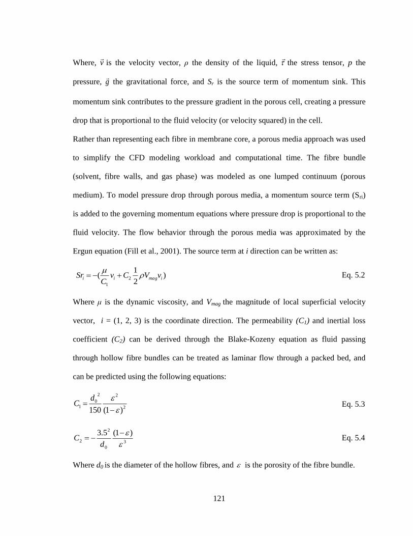
121
Where, v
is the velocity vector, ρ the density of the liquid,
the stress tensor, p the
pressure, g
the gravitational force, and Sr is the source term of momentum sink. This
momentum sink contributes to the pressure gradient in the porous cell, creating a pressure
drop that is proportional to the fluid velocity (or velocity squared) in the cell.
Rather than representing each fibre in membrane core, a porous media approach was used
to simplify the CFD modeling workload and computational time. The fibre bundle
(solvent, fibre walls, and gas phase) was modeled as one lumped continuum (porous
medium). To model pressure drop through porous media, a momentum source term (Sri)
is added to the governing momentum equations where pressure drop is proportional to the
fluid velocity. The flow behavior through the porous media was approximated by the
Ergun equation (Fill et al., 2001). The source term at i direction can be written as:
Eq. 5.2
Where μ is the dynamic viscosity, and Vmag the magnitude of local superficial velocity
vector, i = (1, 2, 3) is the coordinate direction. The permeability (C1) and inertial loss
coefficient (C2) can be derived through the Blake-Kozeny equation as fluid passing
through hollow fibre bundles can be treated as laminar flow through a packed bed, and
can be predicted using the following equations:
Eq. 5.3
Eq. 5.4
Where d0 is the diameter of the hollow fibres, and is the porosity of the fibre bundle.
)2
1( 2
1
imagii vVCvC
Sr
2
22
01
)1(150
dC
3
0
2
2
)1(5.3
dC
122
5.2.2 Continuity Equation and Gas Transport
The following assumptions were made based on the study carried out by Catapano et al.
(Catapano et al., 2001) on membrane oxygenators
1. Steady-state;
2. The porous medium was considered as a continuum;
3. Gas phase was treated as a source term in the governing equation and defined on
per-unit total volume;
The mass balance equation that governs the CO2 concentration in the liquid phase can be
written as below:
rLL SCDCv 2 Eq. 5.5
Where is the superficial velocity vector, D is the gas diffusivity in the continuum and
defined as , where is the gas diffusivity in the solvent (water for this study),
Sr is a source term used to describe solute concentration in the gas phase (CO2 for this
study):
Eq. 5.6
Where A is the fibre membrane surface area per unit total volume; kp is the shell-side
mass transport coefficient; H is the Henry’s constant, CG stands for CO2 concentration in
gas phase, and CL refers to concentration of CO2 in the liquid phase. In this study, the
CO2 partial pressure from the gas source was assumed constant along the fiber to simply
the simulation of gas absorption operated under high gas flow rates. This assumption was
tested and validated by comparing the predicted results to the experimental results in the
following sections.
v
wDD wD
)( LGpr CHCAkS

123
The shell-side mass transfer coefficient kp can be calculated through Sherwood number
(Sh).
Eq. 5.7
Where D is diffusivity coefficient of solute in the solvent; dh is the hydraulic diameter. In
loosely packed module with fibre beds, it is found out that dh is the outer diameter of the
fibre (for module with void fraction greater than 0.5) (Mazaheri et al., 2006). The
Sherwood number can usually be expressed as an empirical correlation in the format
shown in Eq. 5.7 (Gabelman et al., 1999) for cross flow HFMCs.
Eq. 5.8
Where Schmidt (Sc) number is calculated by dividing the diffusion coefficient (of solute
in solvent) with the viscosity of the solvent. Reynolds number is given by Eq. 5.9
v
udR h
e
Eq. 5.9
Where Re is Reynolds number, ν is for kinematic viscosity of solvent and u represents
interstitial velocity in the fibre bundles, which can be estimated using the average velocity
across the fibre bundle.
In the present study, empirical correlations developed by Yang et al. (Yang et al., 1993)
based on experimental measurement from cross flow module with different packing
density were used.
For loosely packed modules ( ˃50%),
Eq. 5.10
For loosely packed modules ( ˂50%),
D
kdSh h
ScαRe 0.33βSh
ScRe94.0 0.330.4Sh
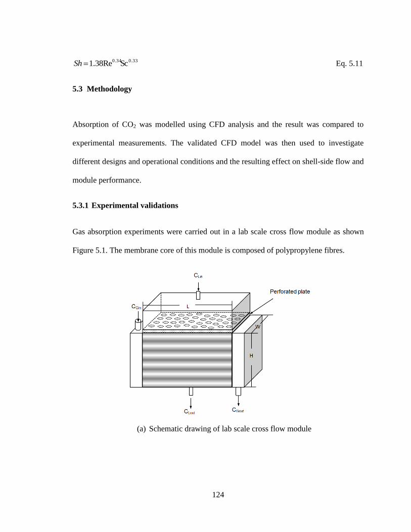
124
Eq. 5.11
5.3 Methodology
Absorption of CO2 was modelled using CFD analysis and the result was compared to
experimental measurements. The validated CFD model was then used to investigate
different designs and operational conditions and the resulting effect on shell-side flow and
module performance.
5.3.1 Experimental validations
Gas absorption experiments were carried out in a lab scale cross flow module as shown
Figure 5.1. The membrane core of this module is composed of polypropylene fibres.
(a) Schematic drawing of lab scale cross flow module
ScRe38.1 0.330.34Sh
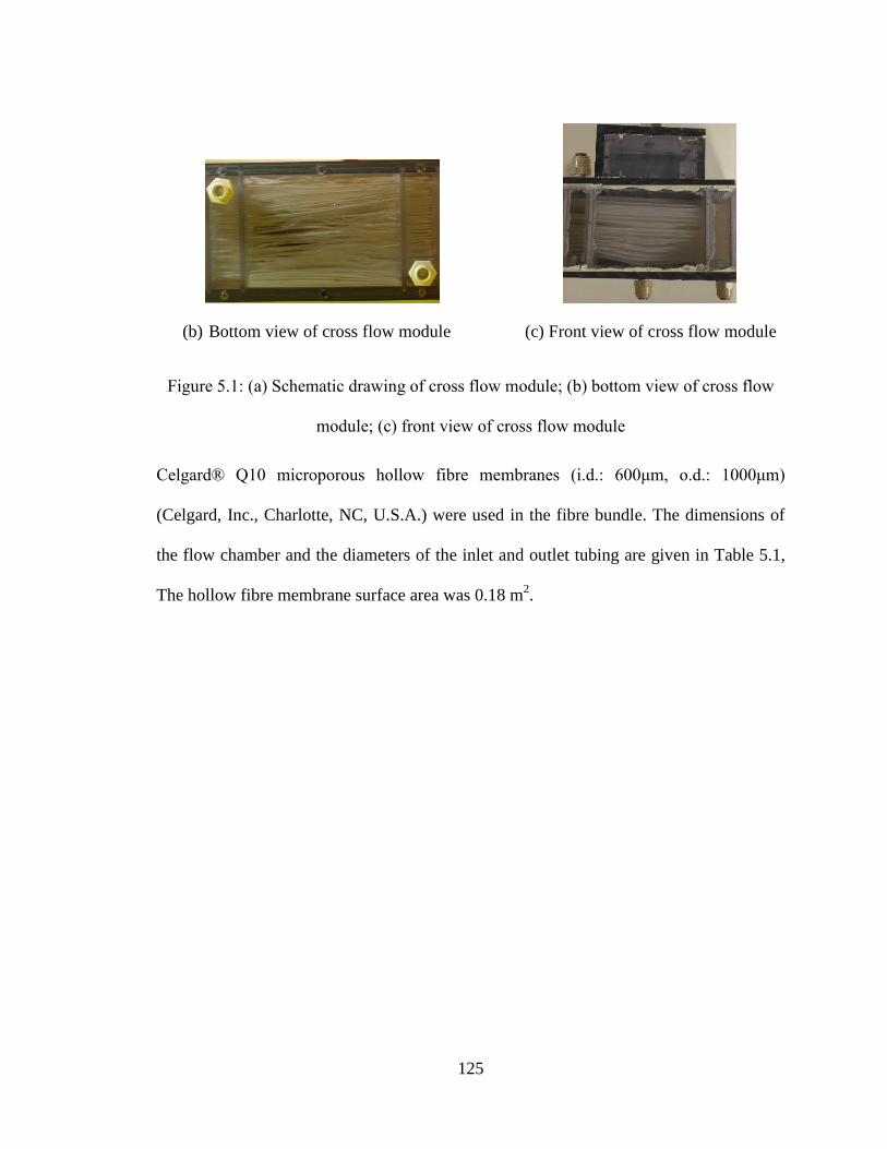
125
(b) Bottom view of cross flow module (c) Front view of cross flow module
Figure 5.1: (a) Schematic drawing of cross flow module; (b) bottom view of cross flow
module; (c) front view of cross flow module
Celgard® Q10 microporous hollow fibre membranes (i.d.: 600μm, o.d.: 1000μm)
(Celgard, Inc., Charlotte, NC, U.S.A.) were used in the fibre bundle. The dimensions of
the flow chamber and the diameters of the inlet and outlet tubing are given in Table 5.1,
The hollow fibre membrane surface area was 0.18 m2.
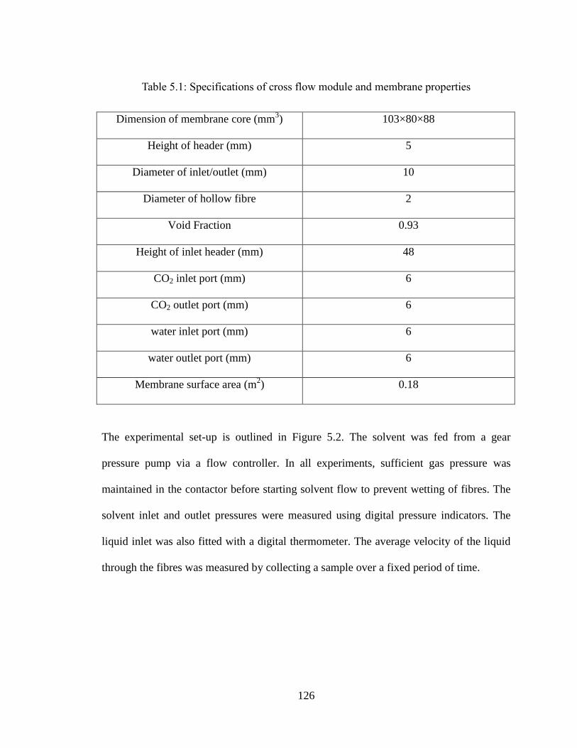
126
Table 5.1: Specifications of cross flow module and membrane properties
Dimension of membrane core (mm3) 103×80×88
Height of header (mm) 5
Diameter of inlet/outlet (mm) 10
Diameter of hollow fibre 2
Void Fraction 0.93
Height of inlet header (mm) 48
CO2 inlet port (mm) 6
CO2 outlet port (mm) 6
water inlet port (mm) 6
water outlet port (mm) 6
Membrane surface area (m2) 0.18
The experimental set-up is outlined in Figure 5.2. The solvent was fed from a gear
pressure pump via a flow controller. In all experiments, sufficient gas pressure was
maintained in the contactor before starting solvent flow to prevent wetting of fibres. The
solvent inlet and outlet pressures were measured using digital pressure indicators. The
liquid inlet was also fitted with a digital thermometer. The average velocity of the liquid
through the fibres was measured by collecting a sample over a fixed period of time.
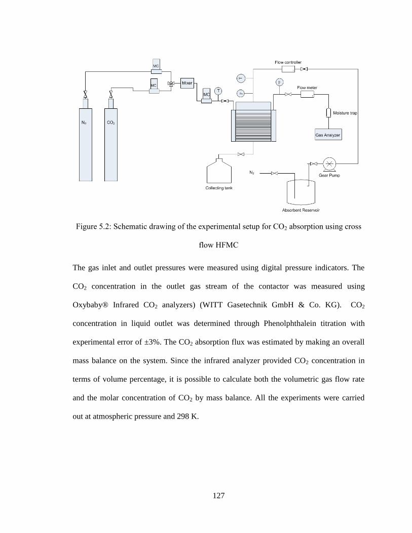
127
Figure 5.2: Schematic drawing of the experimental setup for CO2 absorption using cross
flow HFMC
The gas inlet and outlet pressures were measured using digital pressure indicators. The
CO2 concentration in the outlet gas stream of the contactor was measured using
Oxybaby® Infrared CO2 analyzers) (WITT Gasetechnik GmbH & Co. KG). CO2
concentration in liquid outlet was determined through Phenolphthalein titration with
experimental error of ±3%. The CO2 absorption flux was estimated by making an overall
mass balance on the system. Since the infrared analyzer provided CO2 concentration in
terms of volume percentage, it is possible to calculate both the volumetric gas flow rate
and the molar concentration of CO2 by mass balance. All the experiments were carried
out at atmospheric pressure and 298 K.

128
5.3.2 CFD modeling approach
A three-dimensional geometry and computational surface of the lab scale module was
generated using workbench, ANSYS. The 3-D geometry was then meshed using 3D
Tet/Hybrid elements. An unstructured-mesh finite-volume based commercial CFD
package, Fluent (ANSYS12) was used to solve the governing transport equations for CO2
absorption in the test module.
The solvent (water) was treated as incompressible Newtonian fluid with a constant
viscosity. A pressure-outlet condition was set at the outlet for all simulations. The
absorption performance of the module was investigated with liquid flow rates between
0.1×10⁻⁵
m3/s to 6×10
-5 m
3/s or Reynolds numbers between 0.1 and 10 (laminar regime).
Parameters and physical constants used for the CFD simulations are listed in Table 5.2.
Table 5.2: Parameter used in membrane simulation model
Parameter Value
Water density (kg/m3) 998
DCO2/water (m/s) 2×10⁻⁹
Viscosity (m2/s) 1×10
-6
Temperature (K) 298
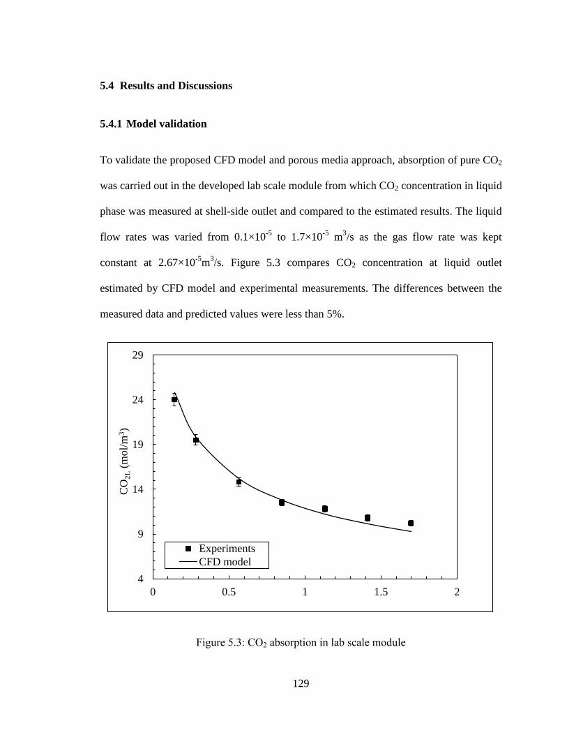
129
5.4 Results and Discussions
5.4.1 Model validation
To validate the proposed CFD model and porous media approach, absorption of pure CO2
was carried out in the developed lab scale module from which CO2 concentration in liquid
phase was measured at shell-side outlet and compared to the estimated results. The liquid
flow rates was varied from 0.1×10⁻⁵
to 1.7×10⁻⁵
m3/s as the gas flow rate was kept
constant at 2.67×10⁻⁵
m3/s. Figure 5.3 compares CO2 concentration at liquid outlet
estimated by CFD model and experimental measurements. The differences between the
measured data and predicted values were less than 5%.
Figure 5.3: CO2 absorption in lab scale module
4
9
14
19
24
29
0 0.5 1 1.5 2
Experiments
CFD model
CO
2L (
mol/
m3)
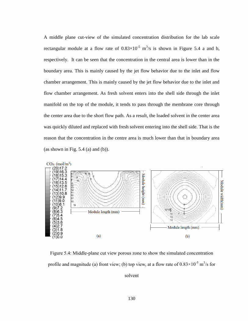
130
A middle plane cut-view of the simulated concentration distribution for the lab scale
rectangular module at a flow rate of 0.83×10⁻⁵
m3/s is shown in Figure 5.4 a and b,
respectively. It can be seen that the concentration in the central area is lower than in the
boundary area. This is mainly caused by the jet flow behavior due to the inlet and flow
chamber arrangement. This is mainly caused by the jet flow behavior due to the inlet and
flow chamber arrangement. As fresh solvent enters into the shell side through the inlet
manifold on the top of the module, it tends to pass through the membrane core through
the center area due to the short flow path. As a result, the loaded solvent in the center area
was quickly diluted and replaced with fresh solvent entering into the shell side. That is the
reason that the concentration in the centre area is much lower than that in boundary area
(as shown in Fig. 5.4 (a) and (b)).
Figure 5.4: Middle-plane cut view porous zone to show the simulated concentration
profile and magnitude (a) front view; (b) top view, at a flow rate of 0.83×10⁻⁵
m3/s for
solvent
131
5.4.2 Impact of module design factors
The module type, structure and geometry are critical design considerations in membrane
performance. To optimize the module design for performance enhancement, the effect of
a series of design factors on shell side hydrodynamic conditions and absorption
performance were investigated using the proposed CFD model, including shell geometry,
inlet geometry (inlet dimension and distributor manifold), fibre bed height and packing
density.
Two parameters are introduced into this study to evaluate the shell side hydrodynamics in
the lab scale cross flow modules: (1) the average shell-side velocity ( shellv ) and (2) flow
maldistribution factor (Sg). Previous studies show that shell-side mixing behavior of the
phase flowing through membrane core is a strong function of shell-side velocity (Dindore
et al., 2005). By discretizing the shell side into grids of finite volumes and solving the
Navier-Stokes equations for each grid, the velocity profile in shell side can be obtained.
The membrane core is where the mass transfer resistance dominates, and therefore the
averaged shell-side velocity can be represented by the averaged fluid velocity across
membrane core (porous zone), which is calculated based on the volume weighted average
on the porous zone. The uniformity of mass flow rate of liquid flow in the shell side (flow
non-uniformity) was described using the flow maldistribution factor (Sg). It is a parameter
used to capture the flow dynamics over a cross section of the membrane core. It has been
widely used to evaluate shell-side flow distribution in the design of plate and fin heat
exchangers (Jiao et al., 2003). It is introduced in the current study to evaluate the The
maldistribution factor can be defined based on the ratio of standard deviation over the

132
mean value of the velocity distribution on the certain cross section of the membrane core,
as shown in Eq.5.12:
×100% Eq. 5.12
Where vi is the local liquid velocity, vave refers to mean liquid velocity for a cross section.
5.4.3 The effect of shell geometry
There are two types of typical shell configurations for cross flow HFMCs: cylindrical and
rectangular as shown in Figure 5.5. Though most modules being commercialized for
industrial application are cylindrical, the potential to improve module performance by
varying shell configuration remains unclear. In this work, the performance of cylindrical
and rectangular modules was compared, keeping other design parameters and operational
conditions constant. The schematic drawing of two modules was shown in Figure 5.6
while the details of module specifications are shown in Table 5.3.
(a) Rectandular module (b) Cylindrical module
ave
n
i
avei
gv
vv
S
1
2)(

133
Figure 5.5: Schematic drawing of rectangular module and cylindrical module
Table 5.3: Specifications of rectangular module and cylindrical module
Module Specification Rectangular module Cylindrical module
Length (mm) 103 103
Width (mm) 88 -
Height (mm) 80 -
Diameter (mm) - 94.6
Volume of membrane core(mm3) 4.5×10
5 4.5×10
5
Total volume (mm3) 7.25×10
5 7.25×10
5
Packing density% 15 15
Membrane area (m2) 0.18 0.18
Absorption of pure CO2 using water as solvent was modeled with CFD analysis. Nitrogen
was bubbled through the water before use to prevent N2 absorption, the initial CO2
concentration in the liquid phase was assumed zero. The absorption flux was compared
by varying liquid flow rate from 0.14×10⁻⁵
to 1.7×10⁻⁵
m3/s. The gas flow rate was kept
constant at 2.67×10⁻⁵
m3/s. The CO2 absorption flux can be calculated using Equation 5.13
and Equation 5.14. The average CO2 concentration at liquid outlet was predicted by CFD
modelling.
Eq.5.13
Eq. 5.14
A
CQCQJ
eGeGiGiG
ave
)( ,,,,
)( ,,,, eGeGiGiGLoutL CQCQCQ
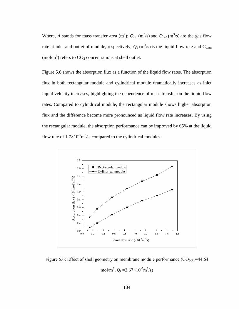
134
Where, A stands for mass transfer area (m2); QG,i (m
3/s) and QG,e (m
3/s) are the gas flow
rate at inlet and outlet of module, respectively; QL (m3/s) is the liquid flow rate and CLout
(mol/m3) refers to CO2 concentrations at shell outlet.
Figure 5.6 shows the absorption flux as a function of the liquid flow rates. The absorption
flux in both rectangular module and cylindrical module dramatically increases as inlet
liquid velocity increases, highlighting the dependence of mass transfer on the liquid flow
rates. Compared to cylindrical module, the rectangular module shows higher absorption
flux and the difference become more pronounced as liquid flow rate increases. By using
the rectangular module, the absorption performance can be improved by 65% at the liquid
flow rate of 1.7×10⁻⁵
m3/s, compared to the cylindrical modules.
Figure 5.6: Effect of shell geometry on membrane module performance (CO2Gin=44.64
mol/m3, QG=2.67×10
-5m
3/s)
135
As the two modules are of the same length, volume and packing density, the difference in
shell-side mass transfer is likely due to various shell-side flow behaviors. Figure 5.7
compares the average shell-side velocity and flow in a cylindrical module and a
rectangular module. At the same flow rate, the rectangular module results in a higher
average shell-side velocity than the cylindrical module, which may explain the better
absorption performance in the rectangular module. The maldistribution factor is
calculated based on the velocity data from the centre of the membrane core. In general,
shell side flow distribution becomes less uniform as liquid flow rate increases. Overall,
the flow distribution in the rectangular module is more uniform than the cylindrical
module. The pressure drop is also critical to membrane performance. Based on the
simulation, the pressure drop was not significantly different between the two designs.
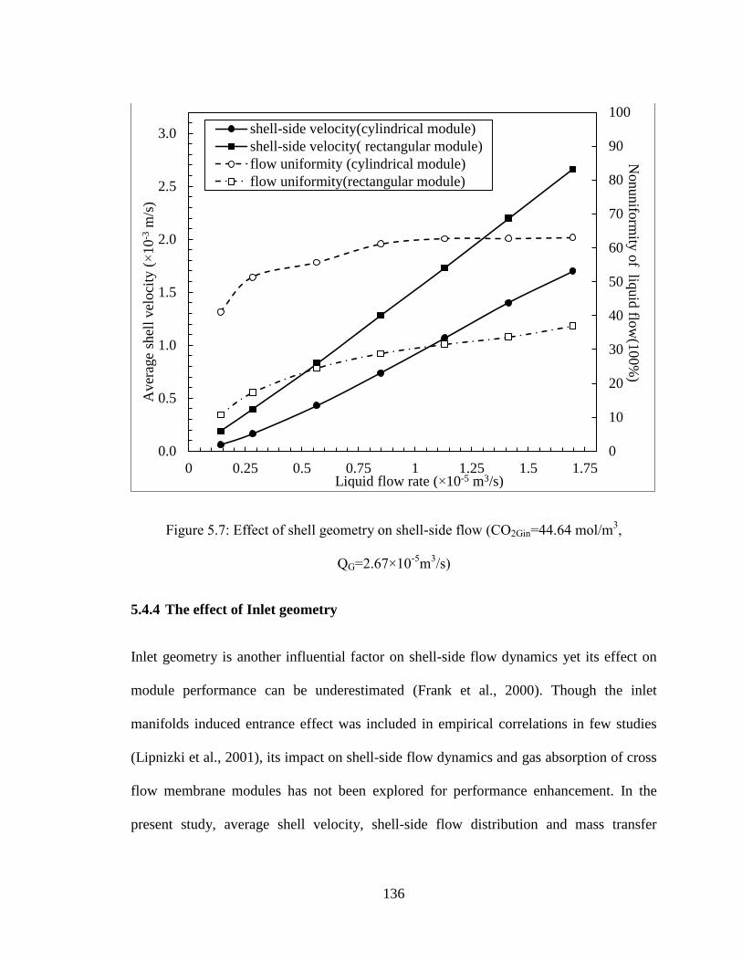
136
Figure 5.7: Effect of shell geometry on shell-side flow (CO2Gin=44.64 mol/m3,
QG=2.67×10⁻⁵
m3/s)
5.4.4 The effect of Inlet geometry
Inlet geometry is another influential factor on shell-side flow dynamics yet its effect on
module performance can be underestimated (Frank et al., 2000). Though the inlet
manifolds induced entrance effect was included in empirical correlations in few studies
(Lipnizki et al., 2001), its impact on shell-side flow dynamics and gas absorption of cross
flow membrane modules has not been explored for performance enhancement. In the
present study, average shell velocity, shell-side flow distribution and mass transfer
0
10
20
30
40
50
60
70
80
90
100
0.0
0.5
1.0
1.5
2.0
2.5
3.0
0 0.25 0.5 0.75 1 1.25 1.5 1.75
shell-side velocity(cylindrical module)
shell-side velocity( rectangular module)
flow uniformity (cylindrical module)
flow uniformity(rectangular module)
Aver
age
shel
l v
elo
city
(×
10
-3 m
/s)
Liquid flow rate (×10-5 m3/s)
Nonunifo
rmity
of liq
uid
flow
(100%
)
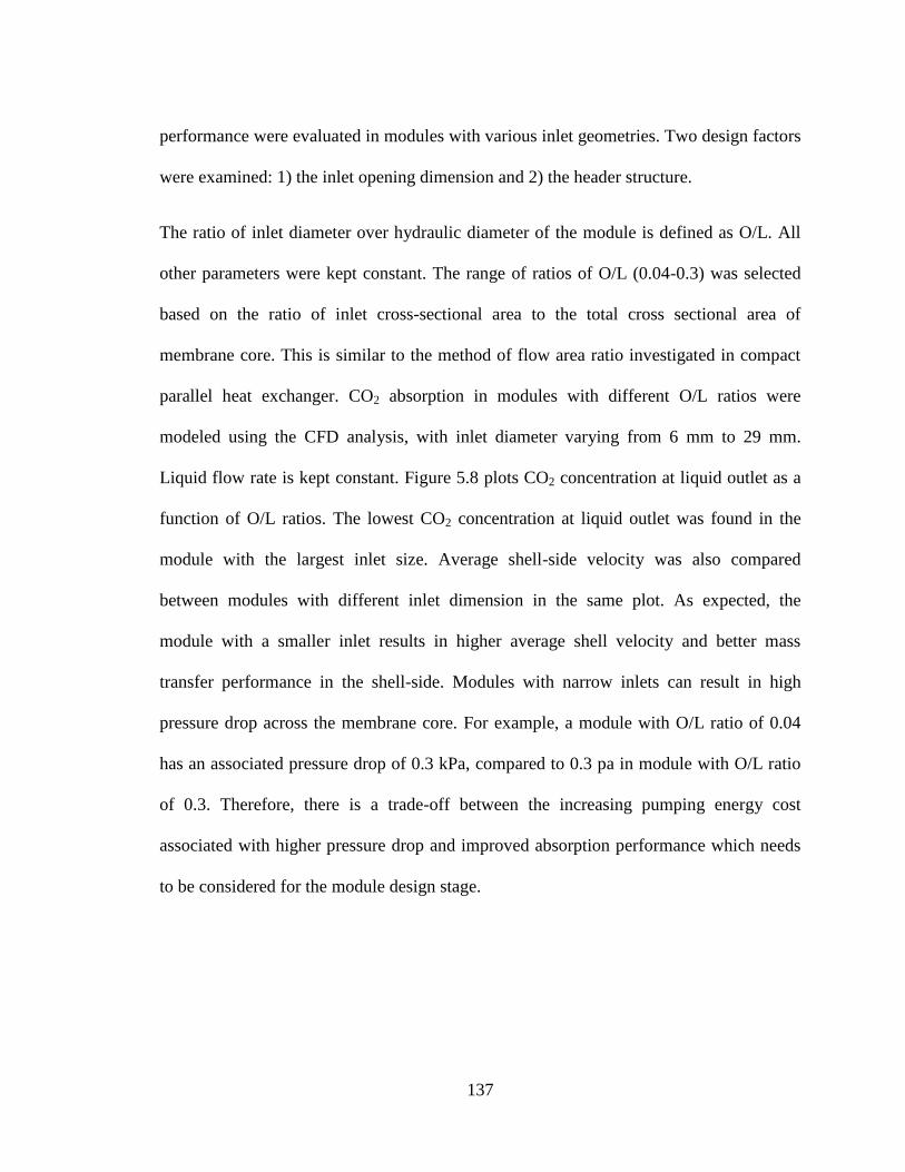
137
performance were evaluated in modules with various inlet geometries. Two design factors
were examined: 1) the inlet opening dimension and 2) the header structure.
The ratio of inlet diameter over hydraulic diameter of the module is defined as O/L. All
other parameters were kept constant. The range of ratios of O/L (0.04-0.3) was selected
based on the ratio of inlet cross-sectional area to the total cross sectional area of
membrane core. This is similar to the method of flow area ratio investigated in compact
parallel heat exchanger. CO2 absorption in modules with different O/L ratios were
modeled using the CFD analysis, with inlet diameter varying from 6 mm to 29 mm.
Liquid flow rate is kept constant. Figure 5.8 plots CO2 concentration at liquid outlet as a
function of O/L ratios. The lowest CO2 concentration at liquid outlet was found in the
module with the largest inlet size. Average shell-side velocity was also compared
between modules with different inlet dimension in the same plot. As expected, the
module with a smaller inlet results in higher average shell velocity and better mass
transfer performance in the shell-side. Modules with narrow inlets can result in high
pressure drop across the membrane core. For example, a module with O/L ratio of 0.04
has an associated pressure drop of 0.3 kPa, compared to 0.3 pa in module with O/L ratio
of 0.3. Therefore, there is a trade-off between the increasing pumping energy cost
associated with higher pressure drop and improved absorption performance which needs
to be considered for the module design stage.

138
Figure 5.8: The effect of inlet dimension on shell-side flow velocity and mixing
(CO2Gin=44.64 mol/m3, QG=2.67×10
-5m
3/s)
Figure 5.9 compares shell-side flow distribution and absorption flux as a function of O/L.
Under the same operational conditions, absorption performance can be improved by using
narrow opening inlet as absorption flux decrease as O/L ratio increases. Moreover,
modules with wider inlets result in more uniform flow distribution in shell-side though
there is no corresponding increase in absorption, likely a result of the aforementioned
higher velocities with narrow inlets and hence higher mass transfer coefficients.
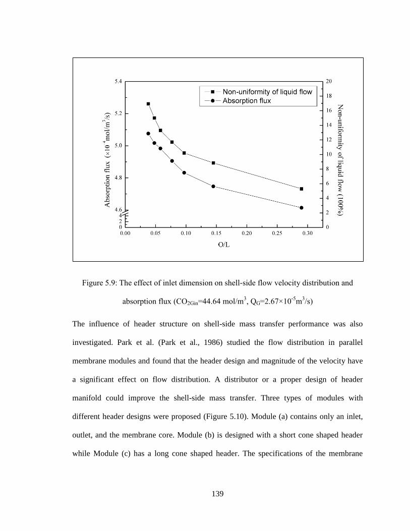
139
Figure 5.9: The effect of inlet dimension on shell-side flow velocity distribution and
absorption flux (CO2Gin=44.64 mol/m3, QG=2.67×10
-5m
3/s)
The influence of header structure on shell-side mass transfer performance was also
investigated. Park et al. (Park et al., 1986) studied the flow distribution in parallel
membrane modules and found that the header design and magnitude of the velocity have
a significant effect on flow distribution. A distributor or a proper design of header
manifold could improve the shell-side mass transfer. Three types of modules with
different header designs were proposed (Figure 5.10). Module (a) contains only an inlet,
outlet, and the membrane core. Module (b) is designed with a short cone shaped header
while Module (c) has a long cone shaped header. The specifications of the membrane

140
core are the same as the specifications in Table 5.1. CO2 concentration at liquid outlet and
average shell velocity from modules with different header geometries were compared in
Figure 5.11 by varying liquid flow rates from 0.14×10⁻⁵
to 5.6×10⁻⁵
m3/s. The impact of
header design on module performance seems insignificant when liquid flow rate is lower
than 0.14×10⁻⁵
. In general, modules with headers result in better performance. The
difference becomes more obvious as liquid flow rate increases. The absorption
performance can be improved by 38.4% when long header is included in module design
at the liquid flow rate of 5.6×10⁻⁵
m3/s, compared to the module without header design.
(a) (b) (c)
Figure 5.10: Schematic drawing of module with different designs of inlet geometries: (a)
Rectangular module without header; (b) Module with short cone shaped header; (c)
Module with long cone shaped header
141
Figure 5.11: The effect of header design on absorption flux (CO2Gin=44.64 mol/m3,
QG=2.67×10⁻⁵
m3/s)
The effect of header design on shell-side hydrodynamics and flow distribution is also
explored and presented in Figure 5.12. Module with longer header results in the highest
average shell velocity compared to the other two modules. This difference becomes more
significant as inlet velocity increases. As outlined above, higher velocities translate into
higher mass transfer coefficient which explains the advantage of using long headers to
prompt shell-side flow. On the other hand, shell-side flow distribution is closely linked to
average shell-side velocity which is more uniform in modules without headers yet its
impact on absorption performance seems insignificant.
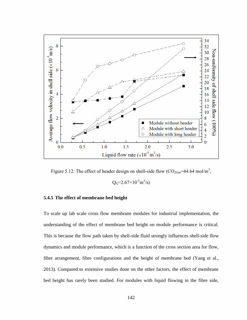
142
Figure 5.12: The effect of header design on shell-side flow (CO2Gin=44.64 mol/m3,
QG=2.67×10⁻⁵
m3/s)
5.4.5 The effect of membrane bed height
To scale up lab scale cross flow membrane modules for industrial implementation, the
understanding of the effect of membrane bed height on module performance is critical.
This is because the flow path taken by shell-side fluid strongly influences shell-side flow
dynamics and module performance, which is a function of the cross section area for flow,
fibre arrangement, fibre configurations and the height of membrane bed (Yang et al.,
2013). Compared to extensive studies done on the other factors, the effect of membrane
bed height has rarely been studied. For modules with liquid flowing in the fibre side,
143
varying the fibre length and number may not make a significant difference on the
performance, as long as the membrane area is kept constant. This is not the case for
modules with liquid flow in the shell-side. In the present study, CO2 absorption in
modules with shallow bed and deep bed was modelled using CFD analysis to investigate
the effect of membrane bed height on shell-side flow dynamics and module performance.
Packing density was assumed constant in all modules. Figure 5.13 compares the estimated
average shell-side velocity and flow maldistribution obtained from modules with
membrane bed height varying from 25 to 306mm.The highest shell-side velocity was
obtained from the module with the shallowest membrane bed, which decreases as the
membrane bed height increases from 25 to 125mm and flattens out as the bed height
continues to increase from 125 to 306mm. In contrast to the velocity, the shell-side flow
distribution in the module with the shallowest bed (i.e., containing only a few layers of
fibres) showed the poorest flow distribution. As membrane bed height increases, the flow
distribution on the exit membrane core is dramatically improved. This is mainly because
the liquid flow is better mixed and distributed as more fibre present in modules with
higher membrane bed height.
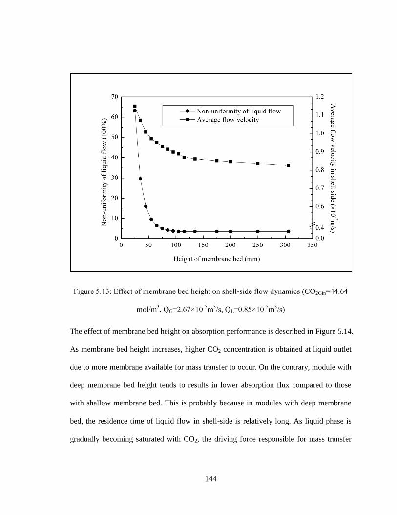
144
Figure 5.13: Effect of membrane bed height on shell-side flow dynamics (CO2Gin=44.64
mol/m3, QG=2.67×10
-5m
3/s, QL=0.85×10
-5m
3/s)
The effect of membrane bed height on absorption performance is described in Figure 5.14.
As membrane bed height increases, higher CO2 concentration is obtained at liquid outlet
due to more membrane available for mass transfer to occur. On the contrary, module with
deep membrane bed height tends to results in lower absorption flux compared to those
with shallow membrane bed. This is probably because in modules with deep membrane
bed, the residence time of liquid flow in shell-side is relatively long. As liquid phase is
gradually becoming saturated with CO2, the driving force responsible for mass transfer
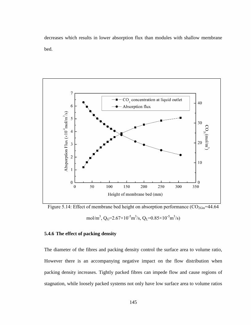
145
decreases which results in lower absorption flux than modules with shallow membrane
bed.
Figure 5.14: Effect of membrane bed height on absorption performance (CO2Gin=44.64
mol/m3, QG=2.67×10
-5m
3/s, QL=0.85×10
-5m
3/s)
5.4.6 The effect of packing density
The diameter of the fibres and packing density control the surface area to volume ratio,
However there is an accompanying negative impact on the flow distribution when
packing density increases. Tightly packed fibres can impede flow and cause regions of
stagnation, while loosely packed systems not only have low surface area to volume ratios
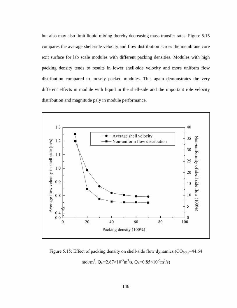
146
but also may also limit liquid mixing thereby decreasing mass transfer rates. Figure 5.15
compares the average shell-side velocity and flow distribution across the membrane core
exit surface for lab scale modules with different packing densities. Modules with high
packing density tends to results in lower shell-side velocity and more uniform flow
distribution compared to loosely packed modules. This again demonstrates the very
different effects in module with liquid in the shell-side and the important role velocity
distribution and magnitude paly in module performance.
Figure 5.15: Effect of packing density on shell-side flow dynamics (CO2Gin=44.64
mol/m3, QG=2.67×10
-5m
3/s, QL=0.85×10
-5m
3/s)
147
Two empirical correlations were used to predict the shell-side mass transfer coefficient
based on a study using cross flow membrane modules with different packing densities
(Yang et al., 1986) (Shown in Equation 5.10 and 5.11). As shown in Figure 5.16, the CO2
concentration at liquid outlet increases from 8.1 to 30 mol/m3 as the packing density
increases from 10% to 50%. The increasing rate gradually flattens out as packing density
continues to increase from 50% to 90%. Less densely packed modules result in higher
absorption flux compared to tightly packed modules while the absorption flux decreases
as packing density increases. This is probably due to higher liquid flow resistance
between fibres in tightly packed modules. As a result, compared to less densely packed
modules, the residence time of liquid in the shell-side is higher in tightly packed modules,
which decreases the driving force for mass transfer. This result agrees well with the
Taskin et al. (Taskin et al., 2010)
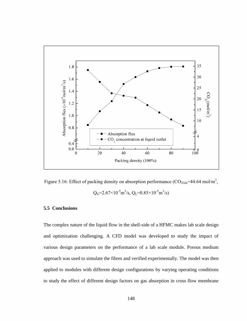
148
Figure 5.16: Effect of packing density on absorption performance (CO2Gin=44.64 mol/m3,
QG=2.67×10⁻⁵
m3/s, QL=0.85×10
-5m
3/s)
5.5 Conclusions
The complex nature of the liquid flow in the shell-side of a HFMC makes lab scale design
and optimization challenging. A CFD model was developed to study the impact of
various design parameters on the performance of a lab scale module. Porous medium
approach was used to simulate the fibres and verified experimentally. The model was then
applied to modules with different design configurations by varying operating conditions
to study the effect of different design factors on gas absorption in cross flow membrane

149
contactors for performance enhancement. When operated under the same conditions, the
rectangular module results in higher shell-side velocities and more uniform shell-side
flow than the cylindrical module. The impact of module design factors such as shell
configurations, inlet geometry, header geometry, fibre bed height and packing density on
shell-side flow dynamics and absorption performance were also investigated. It was found
that the overall shell-side velocity is a key controlling factor in the performance of lab
scale cross flow modules and reduces the impact of shell-side flow distribution. This
study also shows how CFD analysis can be effectively used in the design, scale-up, and
operation of lab scale HFMC. The methodology developed here could be used to
eliminate assumptions (such as constant velocity) which result in inadequate designs and
potentially decrease time and costs associated with residence time distribution and other
tracer tests when evaluating liquid flow characteristics in a lab setting.
150
Reference
Bhaumik, D., Majumdar, S., Sirkar, K.K., Absorption of CO2 in a transverse flow
hollow fibre membrane module having a few wraps of the fibre mat, Journal of
Membrane Science, 138 (1998), 77-82
Catapano, G., Papenfuss, H.D., Wodetzki, A., Baurmeister, U., Mass and momentum
transport in extra-luminal flow (ELF) membrane devices for blood oxygenation,
Journal of Membrane Science, 184 (2001), 123-135
Dannström, H., Natural Gas Sweetening Using Membrane Gas/Liquid Contactors,
presented at The 49th Annual Laurance Reid Gas Conditioning Conference, Norman,
Oklahoma, 1999
Dindore, V.Y., Cents, A.H.G., Brilman, D.W.F.,Versteeg, G.F., Shell-side dispersion
coefficients in a rectangular cross-flow hollow fibre membrane module, Chemical
Engineering Research and Design, 83(A3) (2005), 317-325
Fill, B.J., Gartner, M.J., Johnson, G., Ma, J., Horner, M., Porous media technique for
computational modeling of a novel pump-oxygenator, ASAIO Journal, 51 (2) (2006),
18A.
Frank, A., Lipscomb, G.G., Dennis, M., Visualization of concentration fields in
hemodialyzers by computed tomography, Journal of Membrane Science, 175(2000),
239-251
151
Gabelman, A., Hwang, S., Hollow fibre membrane contactors, Journal of Membrane
Science, 159 (1999), 61-106
Gage, K.L., Gartner, M.J., Burgreen, G.W., Wagner, W.R., Predicting membrane
oxygenator pressure drop using computational fluid dynamics, Artificial Organs 26
(2002), 600-607
Jiao, A., Zhang, R., Jeong, S., Experimental investigation of header configuration on flow
maldistribution in plate-fin heat exchanger, Applied Thermal Engineering, 23 (2003),
1235-1246
Karoor, S., Sirkar, K.K., Gas absorption studies in microporous hollow fibre membrane
modules, Industrial & Engineering Chemistry Research, 32 (4) (1993), 674–684
Lipnizki, F., Field, R. W., Mass transfer performance for hollow fibre modules with shell-
side axial feed flow: using an engineering approach to develop a framework, Journal
of Membrane Science, 193 (2001), 195-208
Mat, N.C., Lou, Y., Lipscomb, G.G., Hollow fibre membrane modules, Current
Opinion in Chemical Engineering, 4(2014), 18-24
Mazaheri, A.R., Ahmadi, G., Uniformity of the fluid flow velocities within hollow fibre
membranes of blood oxygenation devices, Artificial Organs, 30 (1) (2006), 10-15
Park, J.K., Chang, H.N., Flow distribution in the fibre lumen side of a hollow fibre
module. AIChE Journal, 32(1986), 1937-1947

152
Skelland, A.H.P., Diffusional Mass Transfer, John Wiley and Sons, New York, USA,
1974
Taskin, M. E., Fraser, K.H., Zhang, T., Griffith, B.P., Wu, Z. J., Micro-scale modeling of
flow and oxygen transfer in Hollow Fibre Membrane Bundle, Journal of Membrane
Science, 362(1-2) (2010), 172-183
Wickramasinghe, S.R., Semmens, M. J., Cussler, E.L., Mass transfer in various hollow
fibre geometries. Journal of Membrane Science, 69(1992), 235-250
Yang, M.C., Cussler, E. L., Designing hollow-fibre contactors, AIChE Journal, 32 (11)
(1986), 1910-1916
Yang, X., Wang, R., Fane, A. G., Tanga, C. Y., Wenten, I.G., Membrane module design
and dynamic shear-induced techniques to enhance liquid separation by hollow fibre
modules: a review, Desalination and Water Treatment, 51(2013), 16-18
Yang, X., Wong, R., Fane, A.G., Novel designs for improving the performance of hollow
fibre membrane distillation modules, Journal of Membrane Science 384(1-2) (2011),
52–62
Zhang, J., Nolan, T.D.C., Zhang, T., Griffith, B.P., Wu, Z.J., Characterization of
membrane blood oxygenation devices using computational fluid dynamics, Journal of
Membrane Science, 288 (2007), 268-279
153
Zhang, L.Z., Li, Z.X., Zhong, T.S., Pei, L.X., Flow maldistribution and performance
deteriorations in a cross flow hollow fibre membrane module for air humidification,
Journal of Membrane Science, 427 (2013), 1-9
Zheng, J., Xu, Y., Xu, Z., Flow distribution in a randomly packed hollow fibre membrane
module, Journal of Membrane Science, 211(2003), 263-269

154
Chapter 6
NUMERICAL STUDY OF GAS ABSORPTION-
DESORPTION IN DUAL MEMBRANE CONTACTORS
USING CFD MODELING
———————————————————————————————————
This chapter is based on and modified based on the following paper
Cai, J.J., Hawboldt, K., Abdi, M.A., Numerical Study of Gas Absorption-Desorption
with Dual Membrane Contactors Using CFD Modeling, Chemical Engineering Journal,
under-review
155
As discussed in Chapter 5, the CFD modeling approach is an effective design tool to
explore and evaluate novel design of cross flow HFMC used for gas absorption. In
Chapter 5, the CFD model was used to investigate the impact of shell geometry on the
shell side flow dynamics and the impact of shell geometry on the overall module
performance. One critical assumption made to develop the model in Chapter 5 is that the
partial pressure of target gas component from the gas source was constant across a cross
sectional area (e.g. in the radial or y-direction). This assumption is useful for studying
liquid flow dynamics, but would not be valid for actual operation, where locale mass
transfer will impact overall rates. Therefore, in this chapter, the CFD model is expanded
to model the local concentration profile in both fibre and shell side of the proposed dual
membrane contactor.
In sections 6.1 and 6.2 the modified CFD model is outlined. In section 6.3, experiments
are compared to modeled results to validate the model. In section 6.4, the model is used
as a design tool to study the performance of HFMC with more complex geometries such
as baffled modules and modules containing unevenly distributed fibre bundles.
6.1 Background
Currently, one of the most commonly used approaches to predict shell side flow and mass
transfer module performance of cross flow membrane contactors is to develop empirical
correlations for modules with specific designs (Yang et al., 1986; Gabelman et al., 1999;
Dindore et al., 2005). This approach is effective in predicting overall module performance
but cannot provide information on concentration profile and local concentration driving
156
force in the shell side. To gain an understanding of the driving force and concentration
profiles within the module, Dindore et al. (Dindore et al., 2005) used an analytical
approach based on heat transfer to describe the mass transfer in cross flow contactors.
The heat transfer analogy tends to over-predict the module performance at the higher
removal rates as the impact of volumetric flow is not accounted for in the model. In the
same study, a numerical model was developed to describe and predict local concentration
profiles taking into account shell-side mixing. This model however is limited to modules
with solvent flowing in fibre side. In addition, the model cannot account for flow
distribution in the shell, which has proved to be a critical factor in module performance.
Hence, efforts are still needed in developing more rigorous models that can be used to
predict shell side flow and performance of modules with complex geometries on shell
side flow patterns.
Computational fluid dynamics (CFD) has been proven useful tool in characterizing shell
side flow dynamics and mass transfer performance in membrane modules (Darcovich et
al., 1997; Rezakazemi et al., 2011; Taskin et al., 2010). It can also be used to investigate
the connection of module fabrication and processing engineering. Cai et al., (Cai et al.,
2016) developed a CFD model as a screening design tool to evaluate the performance of
cross flow membrane modules with various configurations. One critical assumption made
in this study was that the partial pressure of target gas component from the gas source was
constant across a cross sectional area (e.g. in the radial or y-direction). Though the
proposed model was effective in predicting the overall performance of membrane module,
the locale mass transfer could not be accurately reflected.
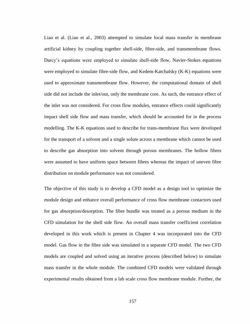
157
Liao et al. (Liao et al., 2003) attempted to simulate local mass transfer in membrane
artificial kidney by coupling together shell-side, fibre-side, and transmembrane flows.
Darcy’s equations were employed to simulate shell-side flow, Navier-Stokes equations
were employed to simulate fibre-side flow, and Kedem-Katchalsky (K-K) equations were
used to approximate transmembrane flow. However, the computational domain of shell
side did not include the inlet/out, only the membrane core. As such, the entrance effect of
the inlet was not considered. For cross flow modules, entrance effects could significantly
impact shell side flow and mass transfer, which should be accounted for in the process
modelling. The K-K equations used to describe for trans-membrane flux were developed
for the transport of a solvent and a single solute across a membrane which cannot be used
to describe gas absorption into solvent through porous membranes. The hollow fibres
were assumed to have uniform space between fibres whereas the impact of uneven fibre
distribution on module performance was not considered.
The objective of this study is to develop a CFD model as a design tool to optimize the
module design and enhance overall performance of cross flow membrane contactors used
for gas absorption/desorption. The fibre bundle was treated as a porous medium in the
CFD simulation for the shell side flow. An overall mass transfer coefficient correlation
developed in this work which is present in Chapter 4 was incorporated into the CFD
model. Gas flow in the fibre side was simulated in a separate CFD model. The two CFD
models are coupled and solved using an iterative process (described below) to simulate
mass transfer in the whole module. The combined CFD models were validated through
experimental results obtained from a lab scale cross flow membrane module. Further, the

158
absorption performance of baffled modules and the module with unevenly distributed
fibre bundles were also modeled using CFD analysis for the design purpose.
6.2 Materials and methods
The model was validated with experimental measurements from a lab scale dual
membrane module (shown in Figure 6.1) by comparing the results of CO2 absorption
from CO2/N2 mixture. This module is composed of a rectangular inlet header, rectangular
membrane core and outlet. A perforated plate is used between the inlet header and
membrane core to improve shell side flow distribution. The specifications of the lab scale
module can be found in Table 6.1. In contrast to conventional cross flow membrane
modules, the membrane core in this module is composed to two types of fibres: porous
polypropylene fibres and nonporous silicone rubber fibres, which are arranged in alternate
rows. The porous membrane is used as an absorber for the targeted gas component to
diffuse through while the nonporous membrane functions as a desorber through which the
dissolved gas component is stripped out of solvent, driven by the differential pressure.
The solvent flows in the shell side. The details of the mass transfer performance in this
dual membrane module can be found in our previous studies (Cai et al., 2016).
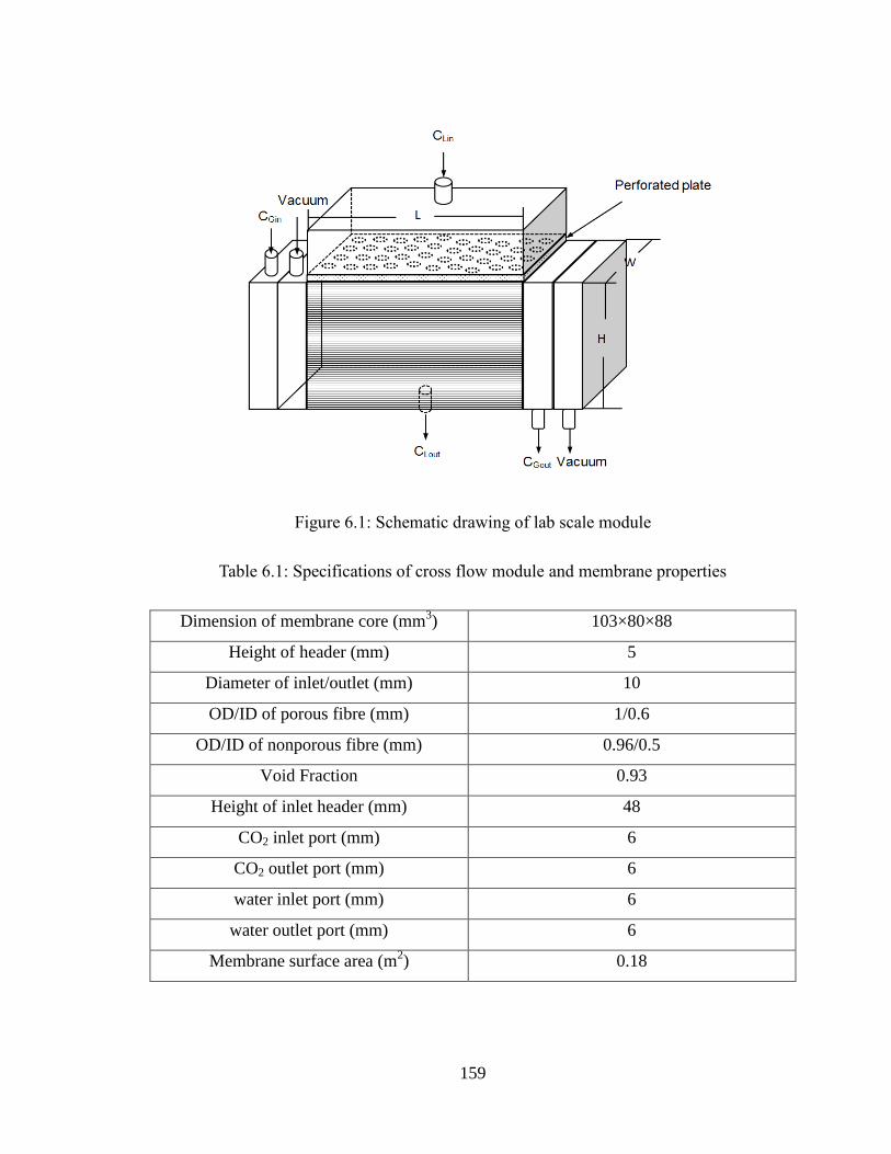
159
Figure 6.1: Schematic drawing of lab scale module
Table 6.1: Specifications of cross flow module and membrane properties
Dimension of membrane core (mm3) 103×80×88
Height of header (mm) 5
Diameter of inlet/outlet (mm) 10
OD/ID of porous fibre (mm) 1/0.6
OD/ID of nonporous fibre (mm) 0.96/0.5
Void Fraction 0.93
Height of inlet header (mm) 48
CO2 inlet port (mm) 6
CO2 outlet port (mm) 6
water inlet port (mm) 6
water outlet port (mm) 6
Membrane surface area (m2) 0.18

160
6.3 Mass transfer model
The model was developed based on the following assumptions:
1. Steady state in both shell and fibre side;
2. Ideal gas behavior is imposed;
3. The membrane pores are filled with gas mixture (non-wetted mode);
4. In shell side, the fibre bundle was modeled as a porous medium where the gas phase
was treated as source term in the governing equation and defined on per-unit total
volume.
These assumptions will be discussed in detail below.
6.3.1 CFD model for shell side flow and mass transfer
The shell side flow behavior is a function of the module inlet/outlet, membrane core and
fibre arrangement. Ideally, the flow fields and local mass transfer inside the module
should be modelled simultaneously. However, this is computationally expensive and time
consuming due to the simulation of thousands of fibres individually. Therefore, in this
study, the membrane core is treated as a porous media in the CFD simulation to predict
the flow fields in shell side. That is, the fibre bundle (solvent, fibre walls and gas phase)
was modeled as one lumped continuum (porous medium). Since the gas absorption was
carried out in our lab scale dual membrane module with Reynolds numbers between 0.3
and 3 for all experiments, the shell side flow is laminar and the mass transfer in the shell
side can be described with Navier-Stokes equations in the steady state as follows.

161
Eq.6.1
Where V, p, ρ, g andτ denote the velocity vector (m/s), the pressure (Pa), the density of
the fluid (kg/m3), the dynamic viscosity (kg/m/s), and gravitational force and stress tensor,
respectively. The porous media is modeled by the addition of a momentum source term
(Sr) to the standard fluid flow equations. The source term is composed of two parts: a
viscous loss term (Darcy, the first part of Eq.6.2), and an inertial loss term (the second
part of Eq.6.2) (Ergun 1952):
Eq.6.2
Whereμ is the dynamic viscosity, Vmag is the magnitude of local superficial velocity
vector. i (i = 1, 2, 3) is the coordinate direction. The permeability (C1) and inertial loss
coefficient (C2) were estimated by the following equations (Ergun, 1952):
Eq.6.3
Where d0 is the outside diameter of the hollow fibres, and ε is the porosity of the fibre
bundle.
The specifications of the crossflow dual membrane module can be found in Chapter 4.
rSgpVV )(
)2
1( 2
1
imagir vVCvC
S
3
0
22
32
01
)1(5.3,
)1(140
dC
dC

162
Figure 6.2: A Cartesian control volume in the porous media for derivation of the species
conservation equation.
For a fluid control volume shown in Figure 6.2, mass balance equation can be established
as follows:
Eq.6.4
Where JD is the mass transfer by diffusion; JC is the mass transfer by convection; JS is the
target gas component source from the gas-phase; JR is the mass transfer rate of dissolved
target gas stripped out of solvent; JΔ is the rate of mass production within the control
volume. At the steady state, the above equation can be derived and simplified into Eq.6.5:
1
2 rCDCv LeffL
Eq. 6.5
Where CL refers to the concentration of target gas in solvent (mol/m3); v is the superficial
velocity vector (m/s), Deff (m/s) is the effective gas diffusivity in the porous medium and
defined as Deff= ɛD, where D is the diffusivity of target gas in solvent. Sr is the source
term and represents the solute from gas phase to liquid per unit volume (Eq.6.6); r is the
sink term representing the dissolved gas stripped out of solvent (Eq.6.7); The porous
JJJJJ rSCD
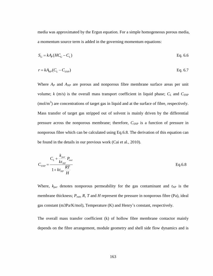
163
media was approximated by the Ergun equation. For a simple homogeneous porous media,
a momentum source term is added in the governing momentum equations:
Eq. 6.6
Eq. 6.7
Where AP and ANP are porous and nonporous fibre membrane surface areas per unit
volume; k (m/s) is the overall mass transport coefficient in liquid phase; CL and CSNP
(mol/m3) are concentrations of target gas in liquid and at the surface of fibre, respectively.
Mass transfer of target gas stripped out of solvent is mainly driven by the differential
pressure across the nonporous membrane; therefore, CSNP is a function of pressure in
nonporous fibre which can be calculated using Eq.6.8. The derivation of this equation can
be found in the details in our previous work (Cai et al., 2010).
Eq.6.8
Where, kper denotes nonporous permeability for the gas contaminant and tNP is the
membrane thickness; Pout, R, T and H represent the pressure in nonporous fibre (Pa), ideal
gas constant (m3Pa/K/mol), Temperature (K) and Henry’s constant, respectively.
The overall mass transfer coefficient (k) of hollow fibre membrane contactor mainly
depends on the fibre arrangement, module geometry and shell side flow dynamics and is
)( LGPG CHCkAS
)( SNPLNP CCkAr
H
RTkt
Pkt
kC
C
NP
out
NP
per
L
SNP
1
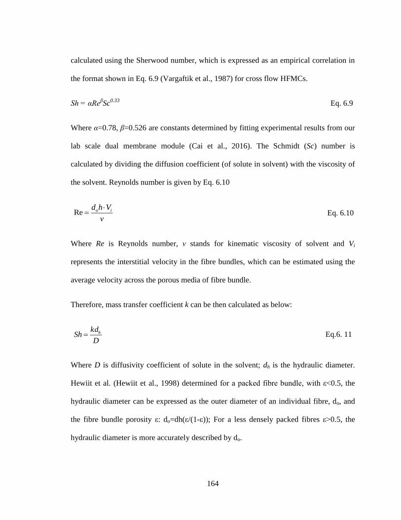
164
calculated using the Sherwood number, which is expressed as an empirical correlation in
the format shown in Eq. 6.9 (Vargaftik et al., 1987) for cross flow HFMCs.
Sh = αReβSc
0.33 Eq. 6.9
Where α=0.78, β=0.526 are constants determined by fitting experimental results from our
lab scale dual membrane module (Cai et al., 2016). The Schmidt (Sc) number is
calculated by dividing the diffusion coefficient (of solute in solvent) with the viscosity of
the solvent. Reynolds number is given by Eq. 6.10
Eq. 6.10
Where Re is Reynolds number, ν stands for kinematic viscosity of solvent and Vi
represents the interstitial velocity in the fibre bundles, which can be estimated using the
average velocity across the porous media of fibre bundle.
Therefore, mass transfer coefficient k can be then calculated as below:
Eq.6. 11
Where D is diffusivity coefficient of solute in the solvent; dh is the hydraulic diameter.
Hewiit et al. (Hewiit et al., 1998) determined for a packed fibre bundle, with ε˂0.5, the
hydraulic diameter can be expressed as the outer diameter of an individual fibre, do, and
the fibre bundle porosity ε: do=dh(ε/(1-ε)); For a less densely packed fibres ε˃0.5, the
hydraulic diameter is more accurately described by do.
v
Vhd io Re
D
kdSh h

165
6.3.2 CFD model for fibre side flow and mass transfer
The arrangement of two types of fibre membrane is shown in Figure 6.3.
Figure 6.3 : Schematic of fibre bundles in the shell side of cross flow dual membrane
module
The flow through porous and porous membrane is shown in Figure 6.4.
Figure 6.4 : Schematic drawing of computational domain for fibre side in the cross flow
dual membrane contactor
The purpose of the model is not to simulate the non-porous membrane removal
independently but rather the impact of liquid flow dynamics on the removal rate. As such,

166
to save computational time the liquid and non-porous fibres are grouped together as a sink
term (see below). The mass transfer of solute from gas phase can be described by a
modified convection-diffusion equation shown in Eq.6.12. That is, the mass transfer rate
in the porous fibre side is determined by convection and diffusion in the gas phase and
diffusion through the membrane wall and liquid layer.
2
2 rCDCv GeffG
Eq.6.12
Where v is the velocity vector of gas phase which can be calculated by solving the
momentum equations of gas phase in the fiber side (m/s), r2 is the sink term and
represents target gas diffusing into the solvent/non-porous fibres:
Eq.6.13
The overall mass transfer coefficient is determined through an empirical correlation
developed in our previous studies (Cai et al., 2016)
At the inlet of fiber side, the concentration of target gas component was kept constant for
each fiber, which can be used as the boundary condition to solve Eq. 6.12.
GiG CC , at x=0 Eq.6.14
6.3.3 Solution methodologies and computer algorithm
The computational domain of the lab scale cross flow module was generated using
computer-aided design software (Workbench from ANSYS). The computational domain
is then divided into a mesh. The resolution of the final mesh was determined varying grid
)(r2 LGp CHCkA

167
resolutions (coarse to fine) to ascertain that the results were grid-independent and
converged quickly. Fluent (v6.2.16, ANSYS, U.S.A.), was used to solve the governing
transport equations.
The overall solution algorithm is outlined Figure 6.5. The equations describing shell side
flow are solved first to calculate the distribution of velocity and concentration in the shell
side. Since the initial concentration distribution in the gas phase is unknown, for the first
iteration the concentration in the gas phase is assumed to be constant along the length of
the fibre and equal to the inlet concentration. The velocity and concentrations obtained
from shell side CFD model are used as input to the fibre side CFD model. The fibre side
CFD model is then run and updated gas concentration profiles in the fibres side (CG). The
results are fed back to the shell CFD model to generate updated concentrations in the
liquid. This process is repeated until the gas concentration in the liquid and gas phase
converge. The convergence criterion is set as (Cn+1
-Cn)/C
n˂10
-6. Parameters and physical
constants used in this study are summarized in Table 6.2.
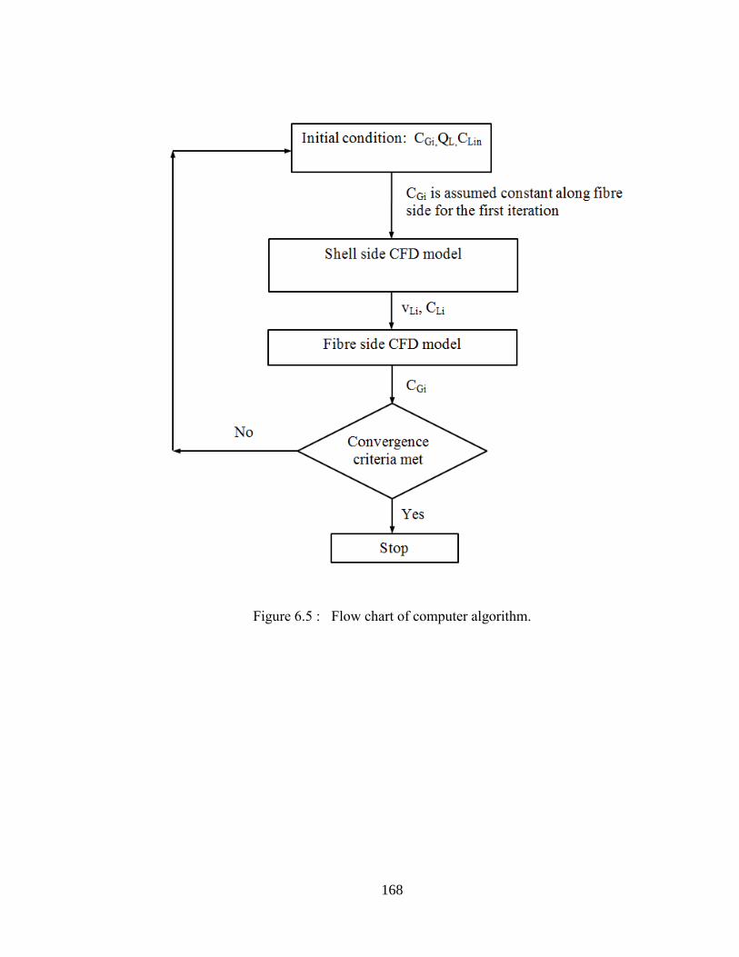
168
Figure 6.5 : Flow chart of computer algorithm.
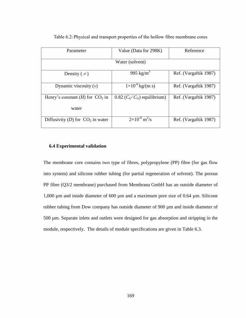
169
Table 6.2: Physical and transport properties of the hollow fibre membrane cores
Parameter Value (Data for 298K) Reference
Water (solvent)
Density (ρ) 995 kg/m3 Ref. (Vargaftik 1987)
Dynamic viscosity (ν) 1×10⁻⁶
kg/(m s) Ref. (Vargaftik 1987)
Henry’s constant (H) for CO2 in
water
0.82 (CL/ CG) equilibrium) Ref. (Vargaftik 1987)
Diffusivity (D) for CO2 in water 2×10⁻⁹
m2/s Ref. (Vargaftik 1987)
6.4 Experimental validation
The membrane core contains two type of fibres, polypropylene (PP) fibre (for gas flow
into system) and silicone rubber tubing (for partial regeneration of solvent). The porous
PP fibre (Q3/2 membrane) purchased from Membrana GmbH has an outside diameter of
1,000 µm and inside diameter of 600 µm and a maximum pore size of 0.64 µm. Silicone
rubber tubing from Dow company has outside diameter of 900 µm and inside diameter of
500 µm. Separate inlets and outlets were designed for gas absorption and stripping in the
module, respectively. The details of module specifications are given in Table 6.3.

170
Table 6.3: Module specifications of cross flow dual membrane module
Module length (mm) 103
Module width (mm) 80
Module height (mm) 80
Porous membrane area (m2) 0.18
Nonporous membrane area (m2) 0.0832
Voidage 0.85
Height of the header (mm) 20
Size of perforated holes (mm) 4
Height of perforated plate (mm) 2
The experimental set-up to evaluate the performance of dual membrane contactor is
shown in Figure 6.6. CO2 was used as the targeted component to be removed from a gas
stream of CO2/N2 mixture. Solvents tested included distilled water and propylene
carbonate (Sigma- Aldrich).
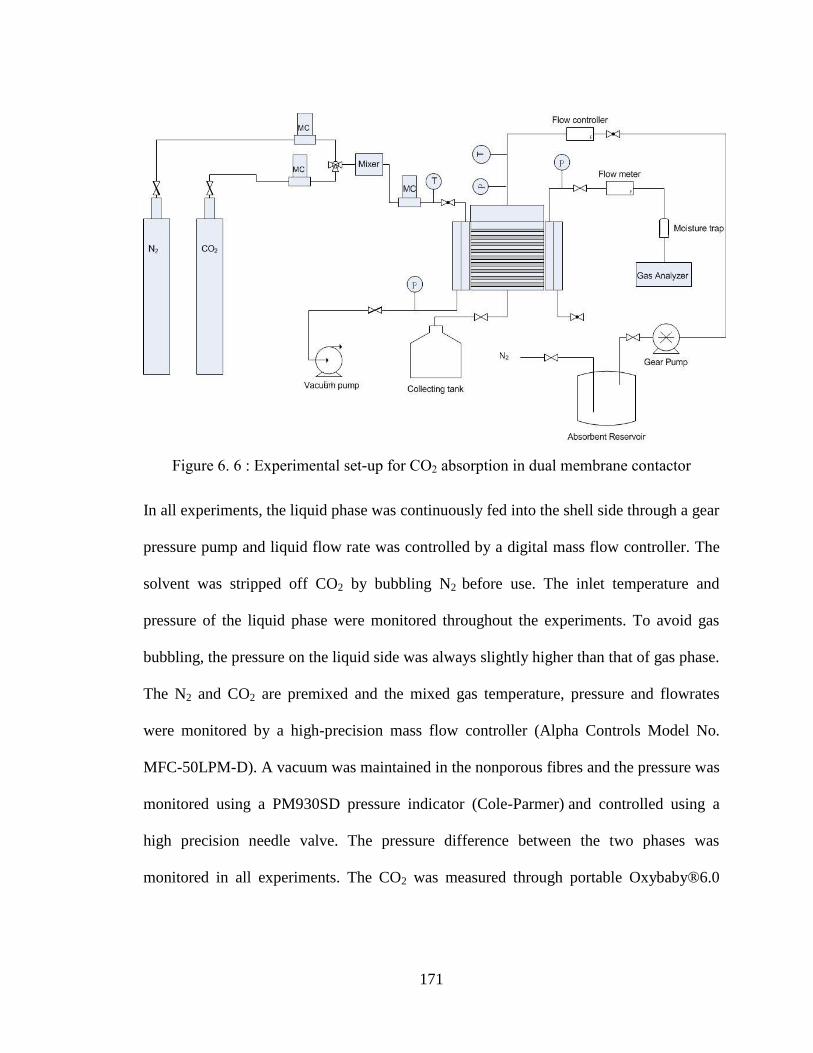
171
Figure 6. 6 : Experimental set-up for CO2 absorption in dual membrane contactor
In all experiments, the liquid phase was continuously fed into the shell side through a gear
pressure pump and liquid flow rate was controlled by a digital mass flow controller. The
solvent was stripped off CO2 by bubbling N2 before use. The inlet temperature and
pressure of the liquid phase were monitored throughout the experiments. To avoid gas
bubbling, the pressure on the liquid side was always slightly higher than that of gas phase.
The N2 and CO2 are premixed and the mixed gas temperature, pressure and flowrates
were monitored by a high-precision mass flow controller (Alpha Controls Model No.
MFC-50LPM-D). A vacuum was maintained in the nonporous fibres and the pressure was
monitored using a PM930SD pressure indicator (Cole-Parmer) and controlled using a
high precision needle valve. The pressure difference between the two phases was
monitored in all experiments. The CO2 was measured through portable Oxybaby®6.0

172
CO2 gas analyzer at gas inlet and outlet. The average CO2 concentration in liquid was
measured via titration.
6.5 Results
6.5.1 Experimental validation of CFD model
Experiments were carried out in our lab scale module for CO2 removal from a gas
mixture of N2/CO2 using water as solvent. Two sets of experiments were carried out using
gas mixtures containing 5% and 30% CO2 respectively. The experimental results were
compared with the simulation results from CFD analysis in terms of CO2 concentration at
gas outlet and liquid outlet. As shown in Figure 6.7, the modelled results agree well with
experimental results. In general, the outlet gas concentration decreases as liquid flow rate
increases due to the fact that the mass transfer resistance resides in the liquid phase is
reduced by increasing the circulating rate of liquid flow.
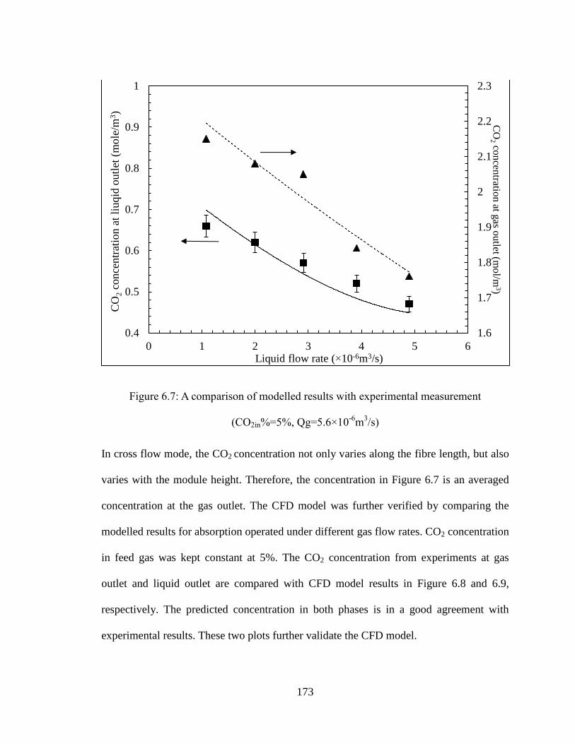
173
Figure 6.7: A comparison of modelled results with experimental measurement
(CO2in%=5%, Qg=5.6×10⁻⁶
m3/s)
In cross flow mode, the CO2 concentration not only varies along the fibre length, but also
varies with the module height. Therefore, the concentration in Figure 6.7 is an averaged
concentration at the gas outlet. The CFD model was further verified by comparing the
modelled results for absorption operated under different gas flow rates. CO2 concentration
in feed gas was kept constant at 5%. The CO2 concentration from experiments at gas
outlet and liquid outlet are compared with CFD model results in Figure 6.8 and 6.9,
respectively. The predicted concentration in both phases is in a good agreement with
experimental results. These two plots further validate the CFD model.
1.6
1.7
1.8
1.9
2
2.1
2.2
2.3
0.4
0.5
0.6
0.7
0.8
0.9
1
0 1 2 3 4 5 6
CO
2 c
once
ntr
atio
n a
t li
uq
id o
utl
et (
mole
/m3)
CO
2 con
centratio
n at g
as ou
tlet (mol/m
3)
Liquid flow rate (×10-6m3/s)
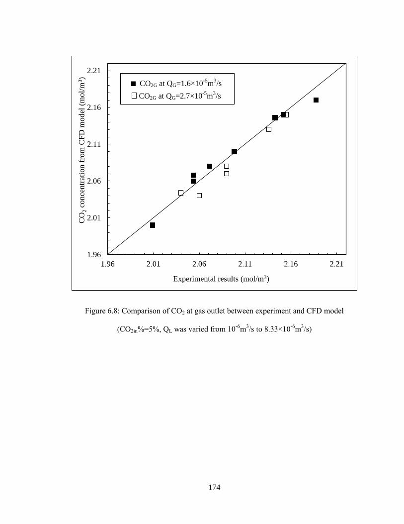
174
Figure 6.8: Comparison of CO2 at gas outlet between experiment and CFD model
(CO2in%=5%, QL was varied from 10-6
m3/s to 8.33×10
-6m
3/s)
1.96
2.01
2.06
2.11
2.16
2.21
1.96 2.01 2.06 2.11 2.16 2.21
Experimental results (mol/m3)
CO
2 c
once
ntr
atio
n f
rom
CF
D m
odel
(m
ol/
m3)
CO2G at QG=1.6×10⁻⁵
m3/s
CO2G at QG=2.7×10⁻⁵
m3/s

175
Figure 6.9: Comparison of CO2 at liquid outlet between experiment and CFD model.
CO2in%=5%, QL was varied from 10-6
m3/s to 8.33×10
-6m
3/s)
The distribution of velocity and concentration is important with respect to scale up and
optimization. A cross sectional view of CO2 concentration distribution predicted by the
CFD model through the fibre bundle along the centreline is shown in Figure 6.10 for a
liquid flow rate of 6.6 ×10⁻⁶
m3/s. The concentration profile is not uniform as the
concentration in the center is lower than at the module boundary, which is mainly caused
by the entrance effect. This is not unexpected however, the question is does this effect
0
0.1
0.2
0.3
0.4
0.5
0.6
0.7
0.8
0.9
1
0 0.1 0.2 0.3 0.4 0.5 0.6 0.7 0.8 0.9 1
Experimental results (mol/m3)
CO
2 c
once
ntr
atio
n f
rom
CF
D m
odel
(m
ol/
m3)
CO2L at QG=1.6×10⁻⁵
m3/s
CO2L at QG=2.7×10⁻⁵
m3/s

176
module performance, as these effects would only be enhanced with scale-up. The
following sections investigate these effects.
Figure 6.10 : CO2 concentration distribution (mol/m3) in porous media (fibre bundles)
(CO2in%=30%, QL=6.6 ×10⁻⁶
m3/s, QG=5.6×10
-6m
3/s)
6.5.2 Performance comparison of dual membrane contactor and absorption column
Performance comparisons between packed columns and membrane contactor have been
reported in the literature by several authors, however most of these work mainly focused
on the gas absorption whereas the solvent regeneraton was not inlcuded in the scope. To
demonstrate the advantage of dual membrane contactor in terms of its capability in size
reduction and reducing solvent consumptionf, the performance of the proposed dual
membrane contactor was compared with that of a lab scale packed column for CO2
absorption. The lab scale packed column (CE-400) used in this study was manufactured
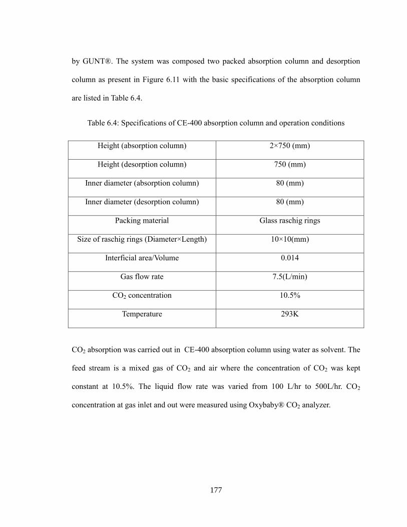
177
by GUNT®. The system was composed two packed absorption column and desorption
column as present in Figure 6.11 with the basic specifications of the absorption column
are listed in Table 6.4.
Table 6.4: Specifications of CE-400 absorption column and operation conditions
Height (absorption column) 2×750 (mm)
Height (desorption column) 750 (mm)
Inner diameter (absorption column) 80 (mm)
Inner diameter (desorption column) 80 (mm)
Packing material Glass raschig rings
Size of raschig rings (Diameter×Length) 10×10(mm)
Interficial area/Volume 0.014
Gas flow rate 7.5(L/min)
CO2 concentration 10.5%
Temperature 293K
CO2 absorption was carried out in CE-400 absorption column using water as solvent. The
feed stream is a mixed gas of CO2 and air where the concentration of CO2 was kept
constant at 10.5%. The liquid flow rate was varied from 100 L/hr to 500L/hr. CO2
concentration at gas inlet and out were measured using Oxybaby® CO2 analyzer.
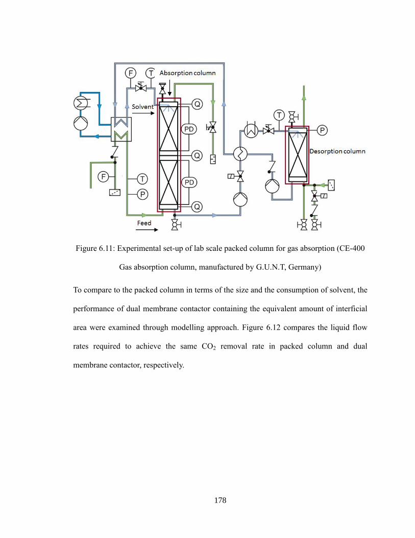
178
Figure 6.11: Experimental set-up of lab scale packed column for gas absorption (CE-400
Gas absorption column, manufactured by G.U.N.T, Germany)
To compare to the packed column in terms of the size and the consumption of solvent, the
performance of dual membrane contactor containing the equivalent amount of interficial
area were examined through modelling approach. Figure 6.12 compares the liquid flow
rates required to achieve the same CO2 removal rate in packed column and dual
membrane contactor, respectively.
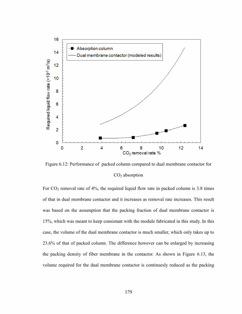
179
Figure 6.12: Performance of packed column compared to dual membrane contactor for
CO2 absorption
For CO2 removal rate of 4%, the required liquid flow rate in packed column is 3.8 times
of that in dual membrane contactor and it increases as removal rate increases. This result
was based on the assumption that the packing fraction of dual membrane contactor is
15%, which was meant to keep consistant with the module fabricated in this study. In this
case, the volume of the dual membrane contactor is much smaller, which only takes up to
23.6% of that of packed column. The difference however can be enlarged by increasing
the packing density of fiber membrane in the contactor. As shown in Figure 6.13, the
volume required for the dual membrane contactor is continuesly reduced as the packing
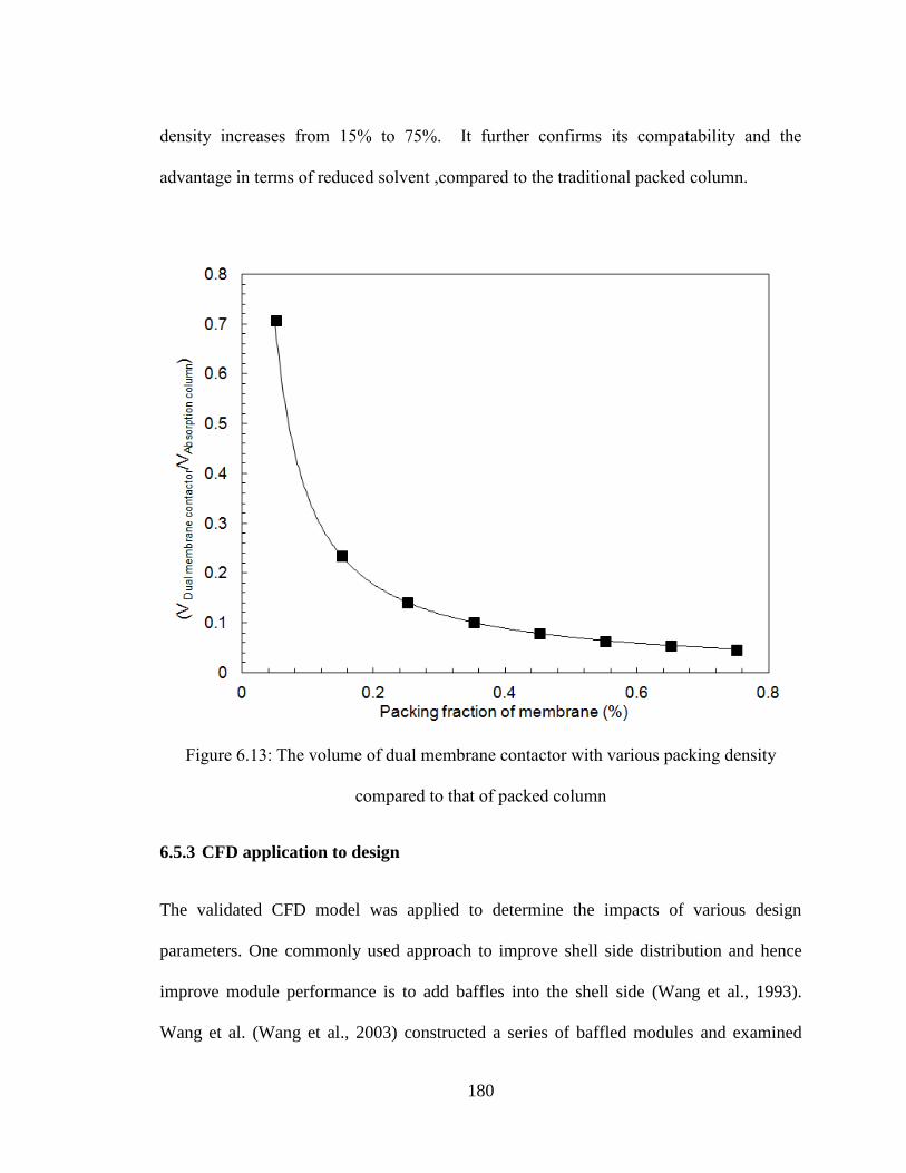
180
density increases from 15% to 75%. It further confirms its compatability and the
advantage in terms of reduced solvent ,compared to the traditional packed column.
Figure 6.13: The volume of dual membrane contactor with various packing density
compared to that of packed column
6.5.3 CFD application to design
The validated CFD model was applied to determine the impacts of various design
parameters. One commonly used approach to improve shell side distribution and hence
improve module performance is to add baffles into the shell side (Wang et al., 1993).
Wang et al. (Wang et al., 2003) constructed a series of baffled modules and examined
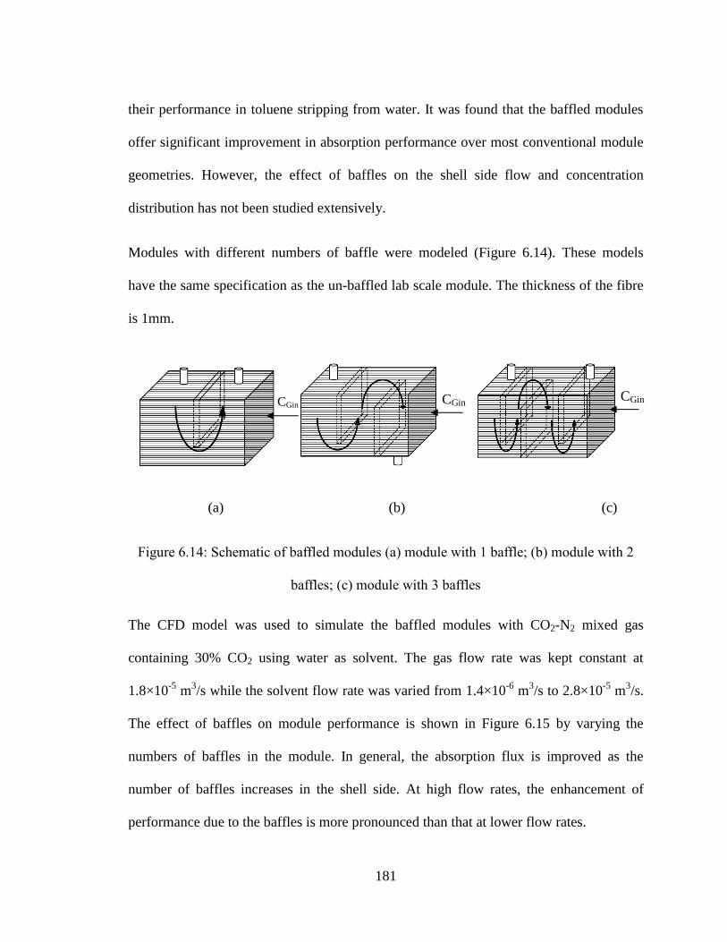
181
their performance in toluene stripping from water. It was found that the baffled modules
offer significant improvement in absorption performance over most conventional module
geometries. However, the effect of baffles on the shell side flow and concentration
distribution has not been studied extensively.
Modules with different numbers of baffle were modeled (Figure 6.14). These models
have the same specification as the un-baffled lab scale module. The thickness of the fibre
is 1mm.
(a) (b) (c)
Figure 6.14: Schematic of baffled modules (a) module with 1 baffle; (b) module with 2
baffles; (c) module with 3 baffles
The CFD model was used to simulate the baffled modules with CO2-N2 mixed gas
containing 30% CO2 using water as solvent. The gas flow rate was kept constant at
1.8×10⁻⁵
m3/s while the solvent flow rate was varied from 1.4×10
-6 m
3/s to 2.8×10
-5 m
3/s.
The effect of baffles on module performance is shown in Figure 6.15 by varying the
numbers of baffles in the module. In general, the absorption flux is improved as the
number of baffles increases in the shell side. At high flow rates, the enhancement of
performance due to the baffles is more pronounced than that at lower flow rates.
CGin CGin CGin

182
Figure 6.15: EEffect of baffle numbers on absorption flux (CO2in%=30%, QG=5.6×10-
6m
3/s)
Adding more baffles adds cost to modules; therefore there is a balance between enhanced
performance and expense. Figure 6.16 summarizes the impact of number of baffles on
performance for a feed gas containing 30% and 100% CO2 respectively while the gas
flow rate and liquid flow rate was kept at 5.6×10⁻⁶
m3/s and 5.6×10
-6m
3/s respectively.
Overall, the absorption flux for absorption of concentrated gas (100% CO2) is higher than
absorption of dilute gas (30% CO2), due to the higher concentration gradient. However,
the effect of baffles on module performance is less significant for dilute gas systems.

183
Figure 6. 16: Effect of solute concentration on the performance of baffled module for CO2
absorption (QG=5.6×10⁻⁶
m3/s, QL=5.6×10
-6m
3/s)
6.5.4 The effect of fibre arrangement on mass transfer
One critical design parameter in HFMC is the distance between fibres and the fibre
arrangement. For loosely packed modules, fibres can be potted one by one and therefore
achieve uniform fibre distribution (i.e. equal distance between each fibre). However,
fibres are usually non-uniformly distributed in tightly packed modules. Wang et al.
(Wang et al., 2003) studied the shell side flow in a parallel flow module through
residence time distribution (RTD) tests and found that the flow was approximated by plug
0
0.2
0.4
0.6
0.8
1
1.2
1.4
1.6
0.0 1.0 2.0 3.0 4.0
Feed gas containing 100% CO2
Feed gas containing 30% CO2
Abso
rpti
on f
lux
×10
-4 (
mol/
m2/s
)
Number of baffles
184
flow in loosely packed modules. Deviation from plug flow increased as the packing
density increased until it reached 50% at which point the flow regime began to once again
approximate plug flow (Wang et al., 2003). The proposed cause for the deviation from
plug flow was the non-uniform fibre distribution. To study the effect of fibre distribution,
a constant local (and overall) packing density was compared with the module with varied
local packing density. To achieve variable local packing density the CFD model
membrane core was divided into three sections with different local packing densities (8%,
13%, and 20%). The overall packing density was 15% for both cases. The feed gas flow
rate was kept constant at 5.6×10⁻⁶
m3/s and liquid flow rate varied from 1.33 ×10
-5 to
1.6×10⁻⁴
m3/s. Figure 6.17 outlines the results. Similar to the observations from Wang et
al. (Wang et al., 2003), the cross flow module with variable local packing densities did
not perform as well compared to a module with uniform packing density.
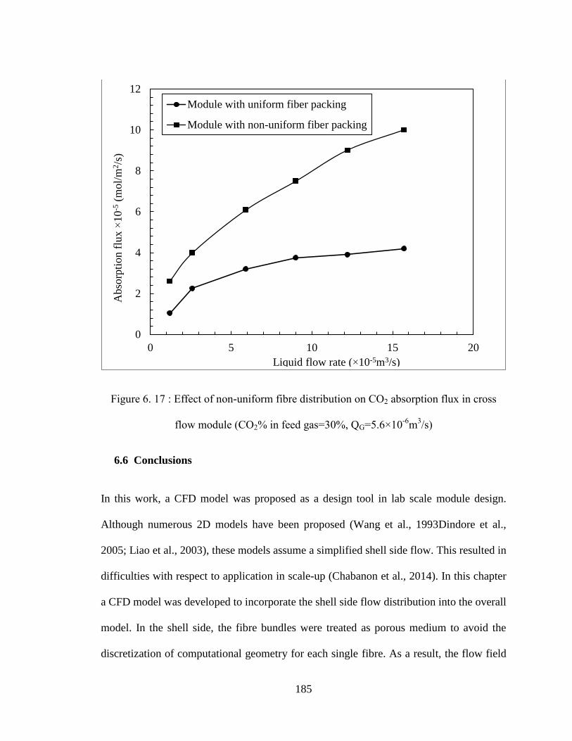
185
Figure 6. 17 : Effect of non-uniform fibre distribution on CO2 absorption flux in cross
flow module (CO2% in feed gas=30%, QG=5.6×10⁻⁶
m3/s)
6.6 Conclusions
In this work, a CFD model was proposed as a design tool in lab scale module design.
Although numerous 2D models have been proposed (Wang et al., 1993Dindore et al.,
2005; Liao et al., 2003), these models assume a simplified shell side flow. This resulted in
difficulties with respect to application in scale-up (Chabanon et al., 2014). In this chapter
a CFD model was developed to incorporate the shell side flow distribution into the overall
model. In the shell side, the fibre bundles were treated as porous medium to avoid the
discretization of computational geometry for each single fibre. As a result, the flow field
0
2
4
6
8
10
12
0 5 10 15 20
Module with uniform fiber packing
Module with non-uniform fiber packingA
bso
rpti
on f
lux
×10
-5 (
mol/
m2/s
)
Liquid flow rate (×10-5m3/s)

186
and shell side mixing which are a strong function of module design and flow dynamics
can be reflected. In the fibre side, the fibres are modelled using the data from the shell
model. The proposed CFD model was validated through experiments using a dual
membrane contactor of bench scale size. It was then used to study various design
parameters for HFMC. The velocity and concentration distribution in cross flow module
shows that the velocity in the centre of the fibre bundle is much higher than the boundary.
This is not unexpected however, the CFD model gives one a tool to determine the extent
of the impact and vary design accordingly. An analysis of adding baffles showed that
baffles not only enhance mass transfer but also this impact varies with dilute versus
concentrated gases. The impact of fibre arrangement on module performance was also
studied through CFD analysis. The result confirms that mass transfer is a strong function
of shell side flow distribution. Modules with more evenly distributed fibre bundles tend to
results in better performance. The analysis here is a subset of possible analyses that could
be done using this CFD model approach. This type of design tool was proven effective in
design optimization, operations, and scale up.
187
Reference
Yang, M.C., Cussler, E. L., Designing hollow-fibre contactors, AIChE Journal, 32 (11)
(1986), 1910-1916
Cai, J.J., Howboldt, K., Abdi, M.A., Improving gas absorption efficiency using a novel
dual membrane contactor, Journal of Membrane Science, 510 (2016), 249-258
Cai, J.J., Hawboldt, K., Abdi, M.A., Contaminant removal from natural gas using dual
hollow fibre membrane contactors, Journal of Membrane Science, 397-398 (2012), 9-
16 Darcovich, K., Dal-Cin, M.M., Ballèvre, S., Wavelet, J.P., CFD-assisted thin
channel membrane characterization module design, Journal of Membrane Science,
124 (2) (1997), 181-193
Chabanon, E., Kimball, E., Favre, E., Lorain, O., Goetheer, E., Ferre, D., Gomez, A.,
Broutin, P., Hollow Fibre Membrane Contactors for Post-Combustion CO2 Capture:
A Scale-Up Study from Laboratory to Pilot Plant, Oil Gas Science Technology, 69
(2014),1035-1045
Dindore, V.Y., Brilman, G. F.,Versteeg, D. W. F., Modelling of cross-flow membrane
contactors: physical mass transfer processes, Journal of Membrane Science, 251
(2005), 209-222
Dindore, V.Y., Cents, A.H.G., Brilman, D.W.F.,Versteeg, G.F., Shell-side dispersion
coefficients in a rectangular cross-flow hollow fibre membrane module, Chemical
188
Engineering Research and Design, 83(A3) (2005), 317-325
Ergun, S., Fluid flow through packed columns, Chemical Engineering Progress 48 (1952),
89-94
Fluent Inc. Fluent 6.2 UDF Manual, Lebanon, NH: Fluent Inc., Feb. 2005
Gabelman, A., Hwang, S., Hollow fibre membrane contactors, Journal of Membrane
Science, 159 (1999), 61-106
Liao, Z., Poh, C.K., Huang, Z., Hardy, P.A. , Clark, W.R., Gao, D., A numerical and
experimental study of mass transfer in the artificial kidney, Journal of Biomedical
Engineering, 125 (2003), 472-480
Rezakazemi, M., Niazi, Z., Mirfendereski, M., Shirazian, S., Mohammadi, T., Pak, A.,
CFD simulation of natural gas sweetening in a gas-liquid hollow-fibre membrane
contactor, Chemical Engineering Journal, 168 (2011), 1217-1226
Taskin, M. E., Fraser, K.H., Zhang, T., Griffith, B.P., Wu, Z. J., Micro-scale modeling of
flow and oxygen transfer in Hollow Fibre Membrane Bundle, Journal of Membrane
Science, 362(1-2) (2010), 172-183
Vargaftik, N. B., Handbook of Physical Properties of Liquids and Gases: Pure Substances
and Mixtures, Hemisphere Publishing Corporation, 1987
Wang, L.K., Cussler, E.L., Baffled membrane modules made with hollow fibre fabric,
Journal of Membrane Science, 85(3) (1993), 265-278

189
Wang, Y., Chen, F., Wang, Y., Luo, G. and Dai, Y., Effect of random packing on shell-
side flow and mass transfer in hollow fibre module described by normal distribution
function, Journal of Membrane Science, 216(2003),81-93
Zhang, J., Nolan, T.D.C., Zhang, T., Griffith, B.P., Wu, Z.J., Characterization of
membrane blood oxygenation devices using computational fluid dynamics, Journal of
Membrane Science, 288(2007),268-279
190
Chapter 7
CONCLUSIONS AND FUTURE WORKS
This chapter summarizes the work being completed and contributions made to the
membrane technology for offshore gas treatment. An outline of future work derived from
this dissertation is also discussed.
7.1 Summary
The last decade has seen an increase in exploitation of unconventional resources of
petroleum in places, such as deep offshore. There are various challenges with both
treating (for re-injection to maintain reservoir pressure to meet flaring regulations etc.)
and/or monetizing these gas reservoirs, principally due to gas quality. The key
contaminants in the gas must be removed depending on the application (for transport vs.
re-injection). Pipelines have a set of specifications need to be met; the liquefied natural
gas requires water, acid gases and heavier hydrocarbons removed, while compressed
natural gas requires water and possibly heavier hydrocarbons removal. The re-injected
gases must be treated to remove sulfur compounds and other contaminants. Space on
191
offshore platforms is limited and therefore large treatment systems are typically not
feasible. Further the performance of contacting equipment can be susceptible to motion
effects. Removal of acid gases, CO2 and H2S is particularly problematic due to energy
and space requirements of typical treatment methods (absorption columns). An alternative
to the conventional gas processing equipment for offshore gas processing is membrane
contactor. The membrane contactor combines the benefits of the membrane separation
and conventional absorption through membrane gas absorption. The primary objective of
this dissertation was to develop a novel membrane contactor with more compact design to
enhance gas absorption efficiency. Experimental study and numerical simulations were
carried out to investigate the performance of the proposed membrane contactor.
7.2 Research Contributions
A novel design of dual membrane contactor module with more compact structure,
smaller footprint and higher performance was proposed and fabricated. The
proposed dual membrane contactor was composed of two types of membranes.
The purpose of the dual membrane approach is to simultaneously absorb the target
gas and partially regenerate the solvent in one unit. The module operates in cross-
flow mode and uses hollow fibre membranes.
A lab scale flow loop was constructed to study the performance of dual membrane
contactor. CO2 absorption using water and propylene carbonate as absorbent were
carried out in lab scale membrane contactor, by varying operational conditions. A
new empirical correlation was developed to describe mass transfer performance in
the proposed dual membrane contactor.
192
Initially a two dimensional mathematical model was proposed to describe the
mass transfer process in the proposed dual HFMC. The concentration of the target
gas component in both gas phase and liquid phase at any position of the module
can be predicted via the numerical model. The numerical model was validated
through lab scale module experiments. In this initial simplified model, the shell
side flow velocity was assumed constant in the module;
A CFD model was developed as a design tool to facilitate and improve the design
of cross flow modules used for gas absorption. To gain an understanding of the
effect of module design on the shell side flow dynamics, the impact of variables
on the overall performance of the membrane module was investigated. These
variables included: the shell side velocity, flow distribution and the concentration
of the target component at the liquid outlet of cross flow modules with various
designs. The impact of a series of module design factors such as shell
configurations, inlet geometry, header geometry, fibre bed height and packing
density were also examined.
To better represent the variable flow in the shell side and tube side of membrane
modules with complex geometries, a two stage CFD model was developed. The
fibre bundle was treated as a porous medium in the CFD simulation for the shell-
side flow. The overall mass transfer coefficient correlation developed in the above
work was incorporated into the CFD model. Flow through the fibre was simulated
in a separate CFD model. The two CFD models were solved using an iterative
process to simulate mass transfer in the whole module. The combined CFD model
was validated using experiment results from a lab scale HFMC. The model was
193
then used to predict the performance of modules with complex structures such as
uneven fibre arrangement and baffles.
The major findings and conclusions of the current research are summarized as follows:
By combining two types of membrane (porous polypropylene membrane and
nonporous silicone rubber membrane) into one unit, simultaneous gas absorption
and partial solvent regeneration can be achieved at the same time in the proposed
dual membrane contactor. As the dissolved gas component is continuously
stripped out of the solvent, the driving force responsible for mass transfer remains
at a high level, which further results in higher absorption flux in the proposed dual
membrane contactor than conventional membrane contactors.
The absorption performance of dual membrane contactor can be enhanced by
adding turbulence promoters such as baffles into shell side. The impact of baffles
on performance enhancement is more pronounced when modules are operated
under low flow.
In cross flow membrane contactors, the concentrations of both fluids vary in both
directions. To describe mass transfer process of gas absorption, a numerical
mathematical model based on mass balance was developed. The numerical
simulation was verified with experimental results. The simulation results showed
that the ratio of porous membrane area and nonporous membrane area was an
influential factor in determining the absorption performance of dual membrane
contactor. The highest gas removal rate was obtained when porous membrane
took up 55% of the total membrane area.
194
To correlate shell-side flow dynamics and mass transfer performance of the
proposed dual membrane contactor, an empirical correlation was developed in this
work based on experimental results of CO2 absorption. The proposed empirical
correlation is a function of liquid flow rate which further confirms that the mass
transfer resistance in the dual membrane system mainly lies in the liquid phase.
To gain a better understanding on the mass transfer process of gas absorption, a
resistance-in-series model was applied to examine the mass transfer resistance
contributed by gas phase, liquid phase and membrane, respectively. The result
from Wilson plot showed that mass transfer resistance from gas phase and porous
membrane could be neglected, comparing to that from liquid phase and nonporous
membrane. Specifically, the nonporous silicone rubber membrane contributes to 7%
of the total mass transfer resistance while the major mass transfer resistance lied
in the liquid phase. Therefore, the module performance of dual membrane
contactor can be further enhanced by increasing liquid flow rate and choosing
nonporous membrane with higher permeability to the target gas component.
The selection of proper absorbent is critical for the development of novel dual
membrane contactors. Two of the most commonly used physical solvents for CO2
absorption (water and propylene carbonate) were compared and examined in
terms of their efficiency for CO2 removal and compatibility with the proposed
dual membrane contactor. The experimental findings suggested that both solvents
could be successfully used in combination with membrane material of the dual
membrane contactor. Mass transfer coefficient in CO2-propylene carbonate
system was lower than that in CO2-water system. Furthermore, the effect of sweep
195
gas stripping on overall absorption in CO2-propylene carbonate system was not as
pronounced as in CO2-water system. This is mainly due to the higher affinity of
propylene carbonate for CO2, which makes it difficult for CO2 to be stripped out
of the liquid phase.
The experimental study of CO2 absorption using the proposed dual membrane
contactor showed that high liquid flow rate, high solute concentration and low
pressure on permeate side promoted high absorption flux whereas gas flow rate
has a limited impact on absorption flux.
The proposed two dimensional numerical model was developed by taking into
consideration of the change of gas flow rate during the absorption process which
was proven to be a critical factor that needs to be accounted for in the simulation.
The simulation results were in good agreement with experimental results for CO2
removal by varying operation conditions.
For cross flow modules operated with liquid solvent flowing through the shell-
side, the overall mass transfer coefficient strongly depends on shell-side flow
behavior and the shell geometries. To address the transport between gas phase and
liquid phase in dual membrane contactor with various geometries, a CFD model
including mass transfer calculation routines was developed. Coupled with the
Navier-Stokes equations, the CFD model was solved and used to study the shell
side hydrodynamics and mass transfer in the proposed dual membrane contactor.
Hollow fibre membrane bundle was treated as a porous medium in the CFD model
whereas the assumption was verified through experimental results.
196
The CFD modeling was used as a design tool to investigate the impact of shell
geometry on the shell side fluid dynamics and the consequent mass transfer.
Compared to fluid distribution, the average shell-side velocity was found to be the
key factor in determining the mass transfer rate. The impact of flow distribution
was found to be less significant. With the local flow fields and concentration
profiles visualized in CFD simulations, it was confirmed that by varying the
design of shell geometry, the shell-side hydrodynamics and mass transfer could be
improved
When operated under the same operational conditions, absorption flux in
rectangular module was found at least 28% higher than cylindrical modules.
Compared to modules with large inlet, modules with narrower inlets resulted in
higher shell-side velocity and absorption and the shell side flow distribution was
less uniform. A cone shaped header improved shell-side flow dynamics and better
absorption performance when compared to modules without, Compared to those
with deep membrane beds, modules with shallow membrane beds performed
better. Modules with higher packing densities had lower absorption fluxes
compared to less densely packed modules. The result indicated that a balance
between gas removal efficiency and absorption flux needs to be taken into
consideration for practical application.
The prediction of localized mass transfer performance of cross flow membrane
modules is challenging. A two stage CFD modeling approach was developed to
simulate mass transfer process in both fiber side and shell side. The proposed
modelling approach included two integrated models to capture concentration

197
change in gas phase and liquid phase. The proposed model was validated against
experimental measurements and was proven to be effective in predicting
concentration change of solute in gas phase and liquid phases. This model is more
accurate but is computationally more expensive in time and effort and therefore
more useful for very detailed analysis. The model used in Chapter 5 of this thesis
is less computationally demanding and could be used as a screening design tool.
Mass transfer in modules with non-uniform fibre distribution and baffled modules
was investigated using the proposed two-stage CFD modeling approach. The
baffles promote shell-side mixing, which resulted in better performance. This was
particularly significant for absorption of gas flows with high levels of the target
gas.
7.3 Publications
Cai, J.J., Hawboldt, K., Abdi, M.A, Contaminant Removal from Natural Gas
using Dual Hollow Fiber Membrane Contactors. Journal of membrane science,
397-398 (2012), 9-16
Cai, J.J., Hawboldt, K., Majid, A., Improving gas absorption efficiency using a
novel dual membrane contactor. Journal of membrane science, 510(2016), 249-
258
Cai, J.J., Hawboldt, K., Majid, A., Analysis of the effect of module design on gas
absorption in cross flow hollow membrane contactors via Computational Fluid
Dynamics (CFD) analysis. Journal of membrane science, 520 (2016) 415-424
198
Cai, J.J., Hawboldt, K., Abdi, M.A, Numerical Study of Gas Absorption-
Desorption with Dual Membrane Contactors Using CFD Modeling, Chemical
Engineering Journal, under-review
Cai, J.J., Hawboldt, K., Abdi, M.A, Investigation and Improvement of Flow
Distribution in Hollow Fiber Membrane Contactor, 63rd CSCHE conference,
Fredericton, Newbrunswick, Canada,2013
Haghighi, M., Cai,J.J, Hawboldt, K. , Abdi, M. A, Sundgaard, C., Hydrate
Prevention in Subsea Oil Production Dead-Legs, Offshore technology conference,
Houston, USA,2013
Kenny, S., Hawboltd, K., Lesley, J. Pan. Y, Cai, J.J., Pipeline transportation
systems for CCS strategies: observations and technology issues, The third
international forum on Transportation of CO2 by pipeline, Newcastle, UK, 2012
Cai,J.J, Hawboldt, K., Abdi, M.A., Contaminant Removal from Natural Gas
using Dual Hollow FiberMembrane Contactors, The 88th Gas Processors
Association Annual Convention, San Antonio, Texas, 2009
Cai,J.J, Hawboldt, K., Abdi, M.A., CO2 Removal from Flue Gas Using Hollow
Fiber Membrane Contactors. The 4th Annual Atlantic Sustainable Campuses
conference, St. John’s, Canada, 2010
7.4 Recommendations for Future work
The most important points of improvement, both in terms of experiments and general
understanding of membrane gas absorbers are summarized below:
199
The effect of operating temperature. The operating pressure and temperature
conditions for offshore gas processing vary widely. The reliability of
polypropylene porous membrane to withstand membrane fouling in high
temperature has not been confirmed yet. More rigorous membrane material such
as ceramic membranes which are able to withstand high temperatures can be
considered.
More complex gas mixtures. For offshore gas processing, the feed stream often
contain more than one targeted gas components needs to be removed such as
removal of CO2 and H2S from sour gas. The gas mixture also impacts membrane
and solvent selection. The current study focused mainly on the principles of gas
absorption at a concept level and therefore single component removal from gas
mixture was selected. Numerical model to describe mass transport in a gas
mixture combined with experiments needs to be further explored and the model
should be further improved and validated through more experimental
investigations.
The effect of membrane wetting over long term operation. Membrane wetting has
a detrimental effect on the performance of membrane module which often occurs
over long term operations. All experiments carried out in the current study were
completed within four hours. The module performance needs to be further
explored over long term operation period.
The effect of mass transfer resistance contributed by gas phase. The mass transfer
resistance contributed by gas phase was found negligible in the lab scale
membrane module for the conditions studied in this work. The mass transfer
200
coefficient in the scaled up parallel module was reported (Chabanon et al., 2013)
smaller than that obtained from lab scale module due to mass transfer resistance
caused by gas maldistribution. This phenomenon needs to be further studied for
the future scaling of the dual membrane module.
Reference
Chabanon, E., Kimball, E., Favre, E., Lorain, O., Goetheer, E., Ferre, D., Gomez, A.,
Broutin, P., Hollow Fibre Membrane Contactors for Post-Combustion CO2 Capture:
A Scale-Up Study from Laboratory to Pilot Plant, Oil Gas Science Technology, 69
(2014),1035-1045