development and production of a film intended for...
TRANSCRIPT

Development and production of a film intended for education and PR in the area of Reactor Technology products
Caroline Bygdeman
Master thesis in Technology and Learning, degree project for the
study programme Master of Science in Engineering and of Education.
Stockholm 2012

2
External supervisor: Mia Ekman, Department of Reactor Technology, Alfa Laval
Supervisor: Henrik Kusar, Department of Chemical Engineering and Technology, Royal Institute of
Technology, KTH
Assistant supervisor: Åsa Julin-Tegelman, Department of Mathematics and Science Education,
Stockholm University, SU
Examiner: Klas Engvall, Department of Chemical Engineering and Technology, Royal Institute of
Technology, KTH
Opponent: Jennifer Minnhagen, Royal Institute of Technology, KTH
Course: SA210X

3
Sammanfattning
Svensk titel: Utveckling och produktion av en film avsedd för utbildning och PR inom området för
reaktorteknologiprodukter.
Examensarbete på programmet Civilingenjör och Lärare inom området Teknik och Lärande
av Caroline Bygdeman.
Avdelningen för reaktorteknologi på Alfa Laval har identifierat svårigheter vid förmedlingen av
kunskap till potentiella kunder. Examensarbetet innefattar utveckling och produktion av en film
avsedd för utbildning och marknadsföring av Alfa Lavals flödesreaktorer, ART® Plate Reactors, för att
förbättra Alfa Lavals sätt att förmedla kunskap till och fånga intresse hos potentiella kunder på
mässor.
Målet med examensarbetet är att filmen ska användas på kemiteknikmässor där reaktorerna ställs
ut, och syftet med arbetet var att med mässbesökarnas förkunskaper som bas utveckla en film som
väcker intresse och samtidigt fungerar som ett lärandemedel.
Genom intervjuer har information om hur mässor går till, önskemål om filmens utformning, samt
bedömning av besökarnas förkunskaper samlats in. Dessa intervjuer, samt litteraturstudier inom
området för kemiska reaktorer och lärande med animation och kommunikation på mässor har legat
till grund för arbetet med framtagandet av filmen.
En storyboard utvecklades, och lade grunden för produktionen av filmen som gjordes i samarbete
med filmbyrån Upper/First i Malmö. Produkten av examensarbetet, filmen, finns att se på
http://youtu.be/PyoX3mVXuYc.
Nyckelord:
Storyboard, Multimodalt lärande, Kontinuerliga flödesreaktorer, Reaktorteknologi, ART® Plate
Reactors

4
Abstract
Master thesis in Technology and learning, degree project for the study programme
Master of Science in Engineering and of Education
by Caroline Bygdeman
The Reactor Technology department at Alfa Laval has identified a difficulty in the mediating of
knowledge to potential customers. The Master Thesis consists of the development and production of
a film intended for education and marketing of the flow reactors at Alfa Laval, the ART® Plate
Reactors, in order to improve Alfa Lavals way of mediate knowledge to potential customers and to
catch their interest.
The purpose of the Master Thesis was to show the film at chemical engineering fairs where the
reactors are exhibited, and the aim of the work was to develop a film which catches interest and
serves as a learning tool with the visitors’ prior knowledge as the basis.
Information about what happens at fairs, requests for the presentation of technical content in the
film and the assessment of the visitors’ prior knowledge was collected through interviews. These
interviews, together with literature studies in the field of chemical reactors, learning with animations
and communications at fairs formed the basis for the development of the film.
A storyboard was developed, and was formed as the basis for the production of the film which was
developed together with the film bureau Upper/First in Malmö, Sweden. The product of the Master
Thesis, the film, can be found at http://youtu.be/PyoX3mVXuYc.
Keywords:
Storyboard, Multimodal learning, Continuous flow reactors, Reactor Technology, ART® Plate Reactors

5
Table of Contents Sammanfattning ...................................................................................................................................... 3
Abstract ................................................................................................................................................... 4
Acknowledgements ................................................................................................................................. 8
Abbreviations .......................................................................................................................................... 9
1. Introduction ................................................................................................................................... 10
1.1 Background to the project ..................................................................................................... 10
1.2 Aim of the Master Thesis....................................................................................................... 10
1.3 Structure of the report .......................................................................................................... 10
1.4 Alfa Laval ............................................................................................................................... 11
1.5 Alfa Laval Reactor Technology Department, ALRT ................................................................ 11
1.6 Upper/First ............................................................................................................................ 11
2. Methods ........................................................................................................................................ 12
2.1 Theoretical studies ................................................................................................................ 12
2.2 Laboratory experiments ........................................................................................................ 12
2.3 Interviews .............................................................................................................................. 12
2.4 Questionnaires ...................................................................................................................... 13
2.5 Processing .............................................................................................................................. 13
2.6 Ethics ..................................................................................................................................... 14
2.7 Analysis of films ..................................................................................................................... 14
2.8 Storyboard ............................................................................................................................. 14
2.9 Work with the film bureau .................................................................................................... 15
3. Technical background .................................................................................................................... 17
3.1 Chemical reactors .................................................................................................................. 17
3.1.1 Batch reactors................................................................................................................ 17
3.1.2 Semi-batch reactors ...................................................................................................... 18
3.1.3 Continuous reactors ...................................................................................................... 18
3.1.4 Batch vs. continuous flow reactors ............................................................................... 20
3.2 Residence-Time Distribution, RTD ......................................................................................... 21
3.3 Characteristics of mixing ....................................................................................................... 22
3.3.1 Macromixing .................................................................................................................. 22
3.3.2 Micromixing ................................................................................................................... 23
3.4 Heat transfer ......................................................................................................................... 23
3.4.1 Heat exchangers ............................................................................................................ 23

6
4. The ART® Plate Reactors from Alfa Laval ....................................................................................... 25
4.1 The Technology ..................................................................................................................... 25
4.2 The product range ................................................................................................................. 27
4.2.1 ART® PR37 ...................................................................................................................... 27
4.2.2 ART® PR49 ...................................................................................................................... 29
4.2.3 ART® LabPlateTM ............................................................................................................. 31
5. Competitors ................................................................................................................................... 32
5.1 Corning Incorporated ............................................................................................................ 32
5.2 Ehrfeld Mikrotechnik BTS, Lonza ........................................................................................... 33
5.3 AM Technology ...................................................................................................................... 34
6. Theories of learning ....................................................................................................................... 35
6.1 The Sociocultural perspective of learning ............................................................................. 35
6.2 Learning with experience and prior knowledge as basis ...................................................... 36
6.3 Multimodal learning .............................................................................................................. 37
7. Lab Experiment .............................................................................................................................. 39
8. Results ........................................................................................................................................... 40
8.1 Interviews .............................................................................................................................. 40
8.1.1 ALRT personnel .............................................................................................................. 40
8.1.2 Representatives from the Alfa Laval Sales Companies ................................................. 41
8.1.3 Customers ...................................................................................................................... 42
8.1.4 Companies that have shown interest in the reactors ................................................... 42
8.2 The receivers of the message of the film .............................................................................. 43
8.2.1 Conclusion of the receivers’ prior knowledge ............................................................... 43
8.3 Analysis of films ..................................................................................................................... 44
8.3.1 Presentation of technical content ................................................................................. 44
8.3.2 Lessons from the films ................................................................................................... 44
8.4 The Storyboard ...................................................................................................................... 44
8.4.1 The overall picture ......................................................................................................... 45
8.4.2 Choice of technical content ........................................................................................... 45
8.4.3 The presentation of the message .................................................................................. 46
8.5 The film .................................................................................................................................. 47
8.5.1 The length of the film .................................................................................................... 47
8.5.2 Link to the film ............................................................................................................... 47
9. Discussion ...................................................................................................................................... 48

7
9.1 Determination of the receivers’ prior knowledge ................................................................. 48
9.2 Evaluation .............................................................................................................................. 49
9.3 Additional uses for the film ................................................................................................... 49
9.4 Improvments and future possibilities ................................................................................... 50
10. Conclusion ................................................................................................................................. 51
11. References ................................................................................................................................. 52
12. Appendix 1 – Lab report ............................................................................................................ 53
13. Appendix 2 – Interview guides .................................................................................................. 53
14. Appendix 3 – Storyboard ........................................................................................................... 53
8
Acknowledgements I would like to thank a number of people for their help during this work.
Firstly, I would like to say a special thank you to Mia Ekman for her invaluable help with difficult
decisions and for support during the whole project. Secondly, Linus Helming, Anders Ernblad and
Tom Thane Nielsen deserve a big thank you for their help, as well as the whole Reactor Technology
department at Alfa Laval for making this Master Thesis a fun experience.
Thank you to all the customers, potential customers, representatives from the Sales Companies and
Alfa Laval for taking your time to be interviewed and for helping me in the process of finding out the
receivers’ prior knowledge.
Thank you to Elias Kristoffersens team at the film bureau Upper/First, for your sharing of experience
in the field of animation production.
Thank you to Åsa Julin-Tegelman and Henrik Kusar, for helping me with the academic part of the
thesis and for your sharing of knowledge in the pedagogical and technical field.
Last but not least, thank you Björn for your support.
Stockholm, May 2012
Caroline Bygdeman

9
Abbreviations
AL Alfa Laval
ALRT Alfa Laval Reactor Technology
C(t) Concentration at time t
cP centipoise ( )
CSTR Continuous Stirred Tank Reactor
Da Damköhler number
E(t) Residence time distribution function
Pe Peclet number
PFR Plug Flow Reactor
PHE Plate Heat Exchangers
PR Plate Reactor
R&D Research and Development
RTD Residence-Time Distribution
SC Sales Companies
U/F Upper/First
v volumetric flow rate
ZPD Zone of Proximal Development

10
1. Introduction In this first part, the aim of the master thesis and the structure of the report are described. The
company Alfa Laval and the Alfa Laval Reactor Technology Department is also presented, followed by
the Upper/First film bureau.
1.1 Background to the project The Reactor Technology department at Alfa Laval has identified a difficulty in the mediating of
knowledge to potential customers. The difficulties that have been identified include the problems
faced when the only tools available when explaining how the ART® Plate Reactors work are texts,
spoken words and still images. To give interested customers the opportunity to see moving images
would simplify many of the problems that occur.
Based on this, the Reactor Technology department at Alfa Laval wanted an educational and
marketing animation about the ART® Plate Reactors to be developed. The idea was to have the film
with them to chemical engineering fairs where the reactors are exhibited, so that the visitors could
watch the film while waiting for their turn to talk to the experts, and simultaneously learn something
about the products.
1.2 Aim of the Master Thesis The aim of the Master Thesis was to plan for and develop a film for educational and marketing
purposes for the products of the department, chemical flow reactors.
Questions:
What is needed for a potential customer to become interested in the reactor?
Which are the important aspects in the development of the film?
Who are the receivers of the film, and what is their level of knowledge in terms of reactor
technology and flow chemistry?
What should be the message of the film?
How should the message be presented in a pedagogical and eye-catching manner for the
best message intake for the receiver in a short period (3 minutes)?
1.3 Structure of the report The report is divided into different parts to make the reading as easy as possible. The report begins
with an overview of the companies involved in the project, the background and a presentation of the
methods that have been used. The next part of the report provides a technical background, and a
presentation of Alfa Laval’s products in the field of reactor technology and their competitors. The
pedagogical background to the project is also presented, including research in the area.
Finally, the results of the project are presented, followed by a discussion and the conclusions that
have been drawn. At the end of the report, a reference list can be found, followed by the appendices.

11
1.4 Alfa Laval Alfa Laval was founded in 1883 by Gustav de Laval, and has been developing products since then. At
that time the name of the company was AB Separator, but in 1963 the company changed name to
Alfa Laval. 1
Alfa Laval is the global leader in its three key technologies: heat transfer, separation and fluid
handling. The company helps customers to warm up, cool down, separate and transport products
like oil, water, chemicals, drinks, food, starches and pharmaceuticals. 2
Today, Alfa Laval has 28 major production units and has customers all over the world. The company
has around 16 000 employees, and the majority of them are located in Sweden, Denmark, France,
India, China and the US. 3
1.5 Alfa Laval Reactor Technology Department, ALRT The Reactor Technology Department at Alfa Laval has its headquarters in Tumba, Sweden. The
project with the reactors started in 1999 with the project name “Advanced Reactor Technology”,
which later gave the trademark ART®.
1.6 Upper/First The film bureau Upper/First, U/F, presents itself as a collective of designers, directors and 3D artists
with passion for design-driven narrative. From their studio in Malmö, Sweden, stunning mix of live-
action, motion graphics and visual effects animation is created for advertising and entertainment in
all formats.4
1 Alfa Laval, http://www.alfalaval.com/about-us/our-company/history/pages/history.aspx 2012-01-12
2 Alfa Laval, ”Välkommen till Alfa Laval”
3 Alfa Laval, http://www.alfalaval.com/about-us/our-company/Pages/our-company.aspx 2012-04-20
4 Kristoffersen, Elias, Upper/First, 2012-04-17

12
2. Methods In this section, the methods of the Master Thesis are presented.
2.1 Theoretical studies To carry out the assignment and to be able to answer the questions concerning the aim of Master
Thesis, an extensive literature study was required.
The literature study was divided into two parts, one technological and one pedagogical. The first of
the purposes of the technological study was to get a general picture of the technical background to
the area of chemical reactors. The second purpose of the technological study was to learn about the
reactor models that should be presented in the film, so an extensive study about the ART® Plate
Reactors from Alfa Laval was performed.
The first part of the pedagogical literature study was to go through texts written about interview
methods and questionnaire methods. These literature studies were done in order to perform the
interviews and questionnaires properly. The second part of the pedagogical study was performed in
order to learn about different ways to present facts in a pedagogical way in films, and to study the
research in the field of multimodal learning.
2.2 Laboratory experiments To learn more about the ART® Plate Reactors, laboratory experiments were performed. In the first
part of the laboratory experiment, the reactor was assembled, and in the second part some tests
were carried out. The first purpose of the experiments was to learn more about one of the reactor
models and to see how it works in practice.
The second purpose of the experiments was to provide Alfa Laval with data on the pressure drop in
the reactor plates as a function of flow rates for liquids with different viscosities.
2.3 Interviews There are two types of research forms, the qualitative and the quantitative research forms. The
qualitative research form primarily seeks for the phenomena’s meaning and content, while the
quantitative research form primarily looks for its frequency. 5 The qualitative interview form
investigates the why and how of decision making, and not just what, where and when. In the
quantitative interview form the questions are standardized, which means that the interviewer should
read the questions in the same intonation in all the interviews or that the surveys should include the
same questions to all the respondents. Differences in the order of the questions or in the
formulations of the questions are not allowed. In the qualitative interview form, the level of
standardization is lower than in the quantitative interviews. In the qualitative interview, the
interview can be adjusted depending on the interviewed person and his/her answers. In this context,
a qualitative research form with interviews was selected.
In the first part of the Master Thesis, qualitative interviews were conducted. A semi-structured
interview model was chosen in order to make sure that the specific problems that were selected
beforehand were addressed during the interviews. A semi-structured interview is focused on specific
topics that the researcher has chosen in advance, and an interview guide has been made beforehand
5 Widerberg, Karin, 2002, p. 15-18

13
containing interview questions and topics. The interview guide can be found in appendix 2. In a semi-
structured interview, the questions do not need to be followed to the letter, but they should serve as
a guide during the interview.6
The topics that were chosen for the interviews were:
What is needed for companies to become interested in the reactor.
The customers’ prior knowledge in terms of reactor technology and process chemistry.
Important aspects in the production of the film.
Five representatives from the Reactor Technology department at Alfa Laval, three representatives
from the Sales organizations at Alfa Laval, and two customers were selected for the interviews
because of their different backgrounds and different experiences, to give as broad an understanding
of the audience as possible. Some of the interviews were performed face-to-face and others over the
telephone because of the long distance between the interviewer and the respondent.
Two representatives from companies that have shown interest in the reactor were also interviewed.
These interviews focused on their knowledge about flow chemistry, what types of questions they
have about the reactors and what they wanted to know more about. Both of these interviews were
performed as telephone interviews.
2.4 Questionnaires Some questions were sent out before the interviews to the customers and to the companies that
have shown interest in the reactor, to let them know what they could expect, and to let them, if they
wanted, prepare their answers. The questions were carefully constructed, and adapted to the target
audience.7 It is easy to construct the questions out of your own point of view, and anyone who works
in a particular area of knowledge easily and sometimes wrongly takes for granted the meaning of the
vocabulary used in that field. 8 The choice of language in the questions was therefore as simple as
possible.
Given the insignificant frequency of response commonly obtained when sending out surveys,
interviewing a selection of customers instead of sending out surveys to many customers was chosen
as the preferred method. Apart from the low frequency of answers from surveys, the respondents do
not have the opportunity to ask if there is something that that they find difficult to understand in the
questions. 9 During an interview, the interviewer can take the opportunity to ask supplementary
questions if something interesting comes up.
2.5 Processing The analysis of the material from qualitative interviews can in many cases be very difficult because of
the extent of the material and the difficulty to interpret it. A transcribed interview can often be very
long, and if many long interviews are done, the amount of material can be overwhelming. In order to
get something useful, there must be tools and methods to process the material.
6 Dalen, Monica, 2008, p. 31
7 Ejlertsson, Göran, 2005. p. 52
8 Ejlertsson, Göran, 2005. p. 52
9 Ejlertsson, Göran, 2005. p. 12

14
All of the face-to-face interviews and most of the telephone interviews were recorded electronically
and transcribed afterwards. To get a better overview of the transcribed interviews, the method
meaning condensation was used. With this method, long statements are compressed into a shorter
form in which the essence of what has been said is described.10 In this way the information was
structured, so that it became easier to sort out what was relevant for the further analysis.
In the telephone interviews where the respondent did not want to be recorded, notes were taken
during the whole conversation. Directly after the interview, time was taken to write out the
interview. It is an advantage to write out the interviews immediately after they have been carried
out, because it allows the best possible representation of what the informants actually have been
saying.11
The coding process is the operation by which data are broken down, conceptualized, and put back
together in new ways.12 The purpose with the coding was to categorize the material to understand
the content in a more theoretical level.
2.6 Ethics Society imposes demands on ethical aspects of all scientific activities in terms of principles, laws and
guidelines. Issues raised in these include requirements of consent, requirements for information and
requirements of confidentiality.13
Before the interviews, the informants were informed about the purpose of the study, and that they
were allowed to refrain from answering some or all questions. They were also informed that their
participation and their answers would be anonymous in the reports and presentations, and that the
interviews which were recorded were listened to by the interviewer only.
2.7 Analysis of films To prepare for this Master Thesis, time was devoted for analysis of existing educational and
marketing films. Focus on the analysis was on how the products were presented in the films, and to
get inspiration. The films were categorized based on personal preference, where the different groups
represented different levels of quality of the films. Questions that were focused on when analyzing
the films were:
In what way is the technical content presented in the film?
What can be learned from the analyzed films for the film that will be developed in the
Master Thesis?
The analysis of the film was also made in order to clarify if the ALRT personnel and I had the same
opinion or not of what a film of good quality looks like.
2.8 Storyboard The work with the development of the storyboard - the strip that explains what happens in the film -
was started some weeks into the theoretical studies, simultaneously as beginning the interview
10
Kvale Steinar, 1997. p. 174 11
Dalen, Monica, 2004. p. 69 12
Dalen, Monica, 2004. p. 74 13
Dalen, Monica, 2004. p. 20-24

15
process. To begin with, an overall picture of what the film should look like was made. This overall
picture was made to obtain an overview of the film as soon as possible, and so that the time
distribution between different parts of the film could be outlined from the start.
The storyboard was made in Microsoft Word, and included explaining pictures, texts and a short
description of what should happen in every sequence. The storyboard was divided into three parts.
The first one was an introduction intended to catch interest, which focused on the comparison
between batch and continuous reactors. The second part focused on the ART® Plate Reactors, on
their features and benefits, while the third part was an ending to the film.
The storyboard was processed in cooperation with ALRT, the Communication Manager at Alfa Laval
and the film bureau.
2.9 Work with the film bureau The work with the film bureau Upper/First started two months into the project. A plan was made in
the first phase of the work, which included both deadlines for the film bureau and deadlines for the
feedback on their work.
Four accept-points were selected in which different parts of the work had to be accepted before the
film bureau could move to the next step in the production. When the film bureau was given an
approval, it was not possible to go back and change what had already been agreed upon without
time delay or extra costs to implement the changes. The work flow with the four accept-points
looked as follows, see Figure 1.

16
Figure 1
Treatment, quote and time plan
Planning
Storyboard
Project start
3D CAD Import
Animatic (3D)
2D/3D Production
Online presentation
Delivery
Follow-up
ACCEPT
ACCEPT
ACCEPT
ACCEPT

17
3. Technical background In this part, a general picture of the technical background to the area of chemical reactors will be
given. This is one part of the results of the technological literature studies.
3.1 Chemical reactors Chemical reactors can be divided into two broad categories; one of them is batch reactors and the
other is continuous reactors.
3.1.1 Batch reactors
A batch reactor is a closed system, which means that the reactor has neither inflow nor outflow of
reactants or products while the reaction is being carried out. To operate a batch reactor, it is filled up
with the reactants, closed and heated up or cooled down to the right temperature before the
reaction starts. When the reaction is finished, the reactor is opened and the product is collected. 14
The batch reactor consists of a vessel that varies in size from small (ml) to very large (m3). In order to
facilitate the heat transfer in the batch reactor, and to achieve a homogenous temperature and
concentration in the reactor, the vessel has an agitator. The agitator consists of a centrally mounted
driveshaft with a drive unit overhead. For an ideal batch reactor, the state of the reactor is constant
in space, but varies in time. 15
Figure 2, Batch reactor
For the heating/cooling system in a batch reactor, heating/cooling coils or external jackets are used
to hold the reactor contents at the desired temperature. To add or remove heat the heat transfer
fluid passes through the coils or jacket. In a batch reactor it takes time to control the temperature, so
therefore it is in many cases unsafe to run exothermic reactions in this type of reactor. A solution to
handle exothermic reactions could be to operate the reactor in semi-batch mode, see 3.1.2.
14
Danielsson, Nils-Åke, 2003, p. 60 15
Danielsson, Nils-Åke, 2003, p. 60

18
Another problem with the batch reactor is that it is difficult to stop the reaction immediately when
needed. Because of this difficulty, byproducts are easily formed, since the wanted product is not
collected immediately. Due to this, the product can be further reacted with unreacted material.
The batch reactors use a batch production technique as a manufacturing method. The batch
production technique manufactures discontinuously - stage by stage over a series of workstations. It
can be useful for small businesses because a single product line can be used to produce several
products. The use of batch reactors is widely established in the industry, especially the
pharmaceutical industry.
One of the advantages with batch reactors are the high conversions that can be obtained when the
reactants have been left in the reactor for long periods of time (if there is no byproduct formation).16
The longer the reactant stays in the reactor, the more the reactant is converted to product until
either equilibrium is reached or all reactions have been converted to product. In a batch reactor, the
conversion is a function of the time the reactants spend in the reactor. The number of moles of A,
that remain in the reactor after a time t, can be expressed in terms of and , where is the
conversion (
) and is the number of moles of A that initially has been fed to
the reactor at the time : 17
[
] [
] [
]
[ ] [ ] [ ]
3.1.2 Semi-batch reactors
A modification of the batch reactor is the semi-batch reactor. The semi-batch reactor consists, like
the batch reactor, of a vessel and an agitator, but unlike the batch reactor it is an open system. It
either has an inflow where one of the reactants can be added slowly during the reaction or an
outflow where the products can be collected during the reaction.18 A semi-batch reactor with an
inflow where one of the reactants is added slowly during the reaction is a common method used
when the reaction is exothermic, and when the heat that is formed must be removed by cooling.
Because these systems have a limitation in heat transfer capabilities, the second reactant is added
pulse wise to minimize the temperature runaway.
The number of moles of A, that remain in the semi-batch reactor after a time t can be expressed,
like the batch reactor, with Equation 1.
3.1.3 Continuous reactors
A continuous reactor handles the product as a flowing stream. In the continuous system the
reactants are simultaneously fed to the reactor and a continuous outflow of products, see Figure 3.
The continuous process is therefore an open system.
16
Fogler, H. Scott, 2009, p. 10-12 17
Fogler, H. Scott, 2009, p. 38-40 18
Danielsson, Nils-Åke, 2003, p. 67

19
Figure 3, Principle of a Continuous reactor
The characteristics of continuous reactors can be divided into different types of ideal reactor
technologies:
CSTR - Continuous Stirred Tank Reactor
PFR - Plug Flow Reactor
The CSTR looks similar to a batch reactor, but unlike the batch and semi-batch reactors, the reactants
flows into the reactor and the products flow out from the reactor simultaneously. See Figure 4 for a
CSTR and Figure 5 for a semi-batch reactor. In a CSTR, the chemical reaction takes place at the
concentration in the outflow. Due to this, the production rate in a CSTR is low. Like a batch reactor,
the CSTR is productive for a long period, but at a lower concentration and rate level.19
Figure 4, Continuous Stirred Tank Reactor20
Figure 5, Semi-batch reactor
In Plug Flow Reactors, the fluid flows through a tube into a larger tube – the so called reactor, and
then out of it again. During the passage through the tube, the composition of the flow changes
gradually along the reactor, as a result of the chemical reaction. The reaction rate varies along the
PFR because the flowing medium is constantly changing along the reactor.21
For a continuous flow system, the conversion increases with increasing reactor volume, so with a
wider or longer reactor, it will take more time for the reactants to flow through the reactor. This
19
Danielsson, Nils-Åke, 2003, s. 74-76 20
Adapted from http://www.mathworks.com/matlabcentral/fileexchange/13556-continuously-stirred-tank-reactor-cstr 2012-05-04 21
Danielsson, Nils-Åke, 2003, s. 90-93
20
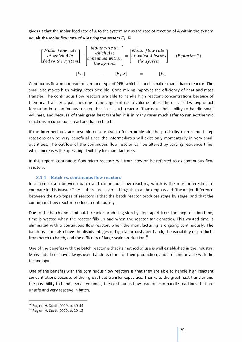
gives us that the molar feed rate of A to the system minus the rate of reaction of A within the system
equals the molar flow rate of A leaving the system : 22
[
] [
] [
]
[ ] [ ] [ ]
Continuous flow micro reactors are one type of PFR, which is much smaller than a batch reactor. The
small size makes high mixing rates possible. Good mixing improves the efficiency of heat and mass
transfer. The continuous flow reactors are able to handle high reactant concentrations because of
their heat transfer capabilities due to the large surface-to-volume ratios. There is also less byproduct
formation in a continuous reactor than in a batch reactor. Thanks to their ability to handle small
volumes, and because of their great heat transfer, it is in many cases much safer to run exothermic
reactions in continuous reactors than in batch.
If the intermediates are unstable or sensitive to for example air, the possibility to run multi step
reactions can be very beneficial since the intermediates will exist only momentarily in very small
quantities. The outflow of the continuous flow reactor can be altered by varying residence time,
which increases the operating flexibility for manufacturers.
In this report, continuous flow micro reactors will from now on be referred to as continuous flow
reactors.
3.1.4 Batch vs. continuous flow reactors
In a comparison between batch and continuous flow reactors, which is the most interesting to
compare in this Master Thesis, there are several things that can be emphasized. The major difference
between the two types of reactors is that the batch reactor produces stage by stage, and that the
continuous flow reactor produces continuously.
Due to the batch and semi batch reactor producing step by step, apart from the long reaction time,
time is wasted when the reactor fills up and when the reactor tank empties. This wasted time is
eliminated with a continuous flow reactor, when the manufacturing is ongoing continuously. The
batch reactors also have the disadvantages of high labor costs per batch, the variability of products
from batch to batch, and the difficulty of large-scale production.23
One of the benefits with the batch reactor is that its method of use is well established in the industry.
Many industries have always used batch reactors for their production, and are comfortable with the
technology.
One of the benefits with the continuous flow reactors is that they are able to handle high reactant
concentrations because of their great heat transfer capacities. Thanks to the great heat transfer and
the possibility to handle small volumes, the continuous flow reactors can handle reactions that are
unsafe and very reactive in batch.
22
Fogler, H. Scott, 2009, p. 40-44 23
Fogler, H. Scott, 2009, p. 10-12

21
The batch reactors are generally larger than the continuous flow reactors, and thanks to the small
size of the continuous flow reactors, it is possible for them to give higher mixing rates than in the
batch reactor types.
3.2 Residence-Time Distribution, RTD The reactors that have been presented so far in the report have been modeled as ideal reactors,
which is not the case in the reality.
The residence time is the period of time that a single molecule spends in the reactor. In the ideal
case, all the molecules are leaving the reactor after exactly the same amount of time. The Residence
Time Distribution, the RTD, is the distribution of all the molecules’ residence times. Some molecules
will spend more time in the reactor than other, due to e.g. incomplete mixing or different velocities
of fluid elements and stagnant zones. In any reactor, the distribution of residence time can
significantly affect the reactor’s performance. 24
To determine the RTD of a continuous flow reactor experimentally, a tracer is injected to the reactor,
and the tracer concentration at the out flow is then measured as a function of time. It is important
that the tracer reflects the behavior of the flowing material through the reactor, and the two most
commonly methods of injecting the tracer are pulse input and step input. 25
In the pulse input method of injection, an amount of the tracer is injected in one shot into the feed
stream, and entering the reactor in as short time as possible. This results in a perfect peak with zero
tail in a Concentration-time (C-t) diagram, as shown in the input curve in Figure 6. At the outlet, the
concentration is measured as a function of time, resulting typically in a C-t curve as shown in the
response curve in Figure 6.
Figure 6
The function that describes how much time different fluids have spent in the reactor in a quantitative
manner is called the Residence-Time Distribution function :
24
Fogler, H. Scott, 2009, p. 868-876 25
Alfa Laval Reactor Technology, Residence Time Distributions and probes
22
is the effluent volumetric flow rate, is the concentration at time , and is the total amount
of the tracer that was injected into the reactor.
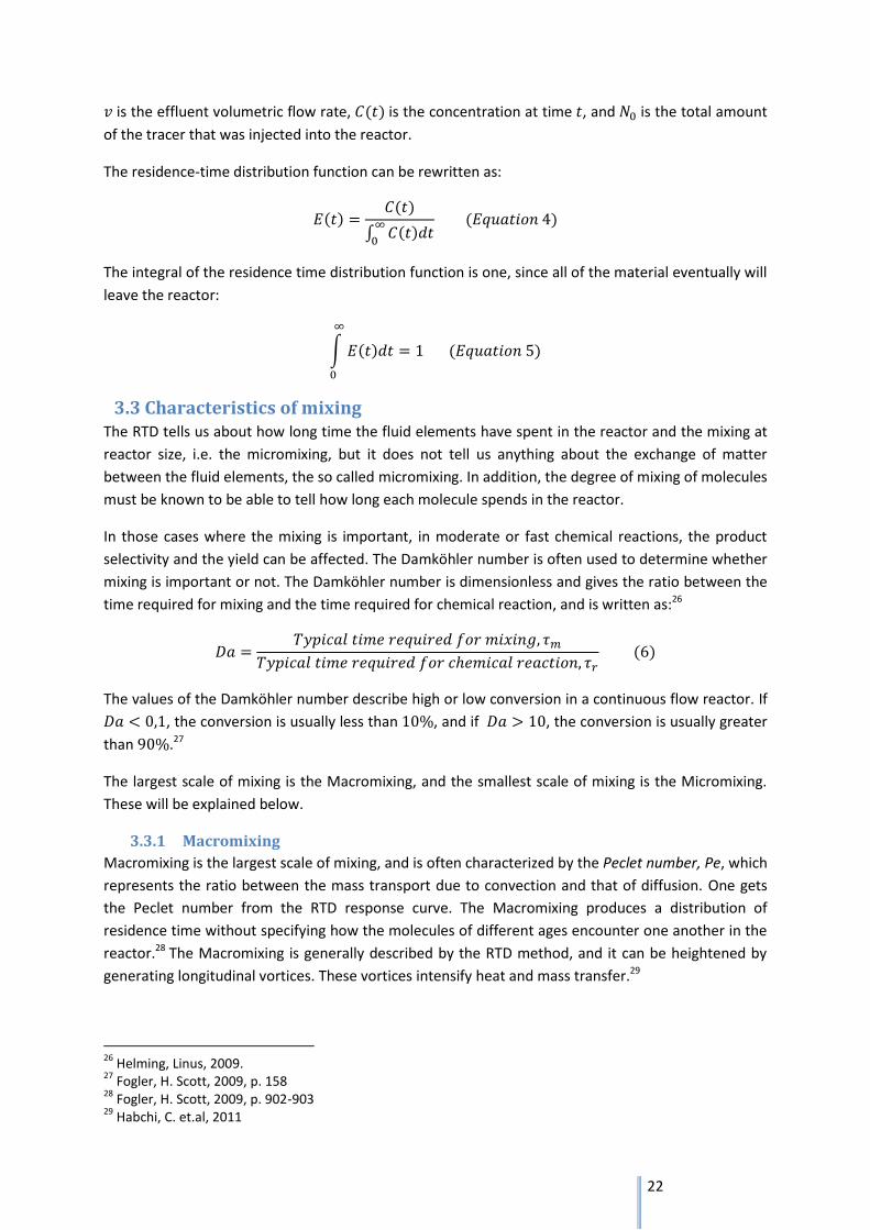
The residence-time distribution function can be rewritten as:
∫
The integral of the residence time distribution function is one, since all of the material eventually will
leave the reactor:
∫
3.3 Characteristics of mixing The RTD tells us about how long time the fluid elements have spent in the reactor and the mixing at
reactor size, i.e. the micromixing, but it does not tell us anything about the exchange of matter
between the fluid elements, the so called micromixing. In addition, the degree of mixing of molecules
must be known to be able to tell how long each molecule spends in the reactor.
In those cases where the mixing is important, in moderate or fast chemical reactions, the product
selectivity and the yield can be affected. The Damköhler number is often used to determine whether
mixing is important or not. The Damköhler number is dimensionless and gives the ratio between the
time required for mixing and the time required for chemical reaction, and is written as:26
The values of the Damköhler number describe high or low conversion in a continuous flow reactor. If
, the conversion is usually less than , and if , the conversion is usually greater
than .27
The largest scale of mixing is the Macromixing, and the smallest scale of mixing is the Micromixing.
These will be explained below.
3.3.1 Macromixing
Macromixing is the largest scale of mixing, and is often characterized by the Peclet number, Pe, which
represents the ratio between the mass transport due to convection and that of diffusion. One gets
the Peclet number from the RTD response curve. The Macromixing produces a distribution of
residence time without specifying how the molecules of different ages encounter one another in the
reactor.28 The Macromixing is generally described by the RTD method, and it can be heightened by
generating longitudinal vortices. These vortices intensify heat and mass transfer.29
26
Helming, Linus, 2009. 27
Fogler, H. Scott, 2009, p. 158 28
Fogler, H. Scott, 2009, p. 902-903 29
Habchi, C. et.al, 2011

23
3.3.2 Micromixing
Micromixing is the smallest scale of mixing, and describes the mixing that takes place on molecular
scale.30 For reactions with fast reaction kinetics, the micromixing is especially important because it
will affect process parameters such as reaction time, yield, heat- and mass transfer. In the
micromixing scale, the laminar stretching leads to interlacing of laminar layers which increases the
mixing.31
3.4 Heat transfer Many reactions are exothermic or endothermic in many chemical processes. The heat transfer
technology often involves bringing two substances at different temperatures close to each other so
that one either heats or cools the other. 32 The driving force for heat transfer is the temperature
difference.
Heat transfer can take place in three different ways:
Conduction
Convection
Radiation
Conduction is the heat transfer that occurs when the heat flows through the body itself, for example
through a plane wall. In solids, conduction is the result of the heat transfer of vibrational energy and
with the energy that is transported by free electrons. In fluids, conduction is a result of the transfer
of kinetic energy by collisions.33
Convection is the heat transfer that is a result of the mixing of fluid elements, i.e. energy exchange
between a surface and an adjacent fluid. It can be either natural, when it is due to the difference in
density, or forced, when it is a result of a turbulent or streamline flow. What should be noted is that
the convection requires mixing of the fluid elements, and that the convection is a result of the
macromixing.34
Radiation is when material emits thermal energy in the form of electromagnetic waves in the range
of . One example of radiation is the way that the sun heats up the earth. All materials
radiate thermal energy, but when this radiation reaches a second body, it can either be reflected,
transmitted or absorbed.35
3.4.1 Heat exchangers
Heat exchangers are used to transfer thermal energy from one medium to another. In many heat
exchangers, before the heat reaches the second medium, it passes through a series of layers which
are located between the two media. In heat exchangers, all of the three modes of heat transfer can
be involved.
30
Fogler, H. Scott, 2009, p. 902-903 31
Habchi, C. et al. 2011 32
http://www.alfalaval.com/service-and-support/performance-upgrades/plate-heat-exchanger-upgrades/Pages/plate-heat-exchanger-upgrades.aspx 2012-04-10 33
Coulson & Richardson’s, 1999, p.381-414 34
Coulson & Richardson’s, 1999, p.381, 414-438 35
Coulson & Richardson’s, 1999, p.381, 438-471

24
If the two fluids in a heat exchanger are flowing in the same direction, in a so called co-current flow,
the temperatures of the two fluids are approaching one another, as shown in Figure 7. If the fluids in
a heat exchanger are flowing in opposite directions, in a so called countercurrent flow, the
temperature difference shows less variation through the heat exchanger than in a co-current flow as
shown in Figure 8.
Figure 7 – Temperature difference, co-current flow36
Figure 8 – Temperature difference, countercurrent flow37
3.4.1.1 Plate Heat Exchangers
Instead of making shell and tube heat exchangers more compact, which results in construction
problems, Plate Heat Exchangers, PHE, are used in order to maximize the heat transfer area per unit
volume of heat exchanger. A PHE, is usually composed of thin parallel plates which are held together
in a frame, and is one of the most general types of heat exchangers.38 These plates are gasketed,
welded or brazed together, depending on which applications the PHE will be used for.39
Each plate has four corner ports, and these corner ports line up to form distribution headers for the
two fluids. The plates are held together in the frame to form the parallel countercurrent flow
channels with alternating hot and cold fluids.40 This is shown in Figure 9 below.
Figure 9, Plate Heat Exchanger, PHE 41
36
KE1030, Transportprocesser och Energiomvandlingar, Lecture 9, KTH 2011 37
KE1030, Transportprocesser och Energiomvandlingar, Lecture 9, KTH 2011 38
Coulson & Richardson’s, 1999, p.548 39
Shah, Ramesh K.; Sekulic, Dusan P., 2003, p. 22-23 40
Shah, Ramesh K.; Sekulic, Dusan P., 2003, p. 22-29 41
http://www.apiheattransfer.com/ 2012-03-15

25
4. The ART® Plate Reactors from Alfa Laval In the film the ART® Plate Reactors from Alfa Laval will be presented. In this chapter, a general
presentation of the technology and a presentation of the different reactors is given.
Figure 10, The ART® Plate Reactors from Alfa Laval42
4.1 The Technology The ART® Plate Reactors are designed as flexible and modular chemical reactors for the
Pharmaceutical, Fine Chemical and Specialty Chemical Industries. They are used to combine and mix
reagents and control their subsequent reactions efficiently and safely.43 The reactors are suitable for
research and process development in the laboratory and for production in the plant.
The ART® Plate Reactors combine the properties of a continuous flow reactor with those of a plate
heat exchanger, which means that it processes the chemical reactants in a continuous flow at a low
volume and that it is composed by reactor plates sandwiched between heat transfer plates. Similar
to a plate heat exchanger, all the reactor models use plate surfaces to control the flow and the
temperature of the reactants. This leads to the reactors being able to safely handle products that in
batch reactors would have been unsafe and very reactive.
All of the reactor models consist of a reactor frame, in which several plate cassettes are stacked
together. Each of these cassettes consists of a process side and a utility side. In the process side, the
process channel in the core of the plate consists of a serpentine path, and it combines multiple
changes of both direction and channel width. In the process channel, the reactants can be mixed
together in small quantities. Thanks to the unique design of channels with bulges, see Figure 11,
mixing is increased and efficient heat transfer can be accommodated.
42
Internal pictures 43
Alfa Laval Reactor Technology, Poster Informex 2011

26
Figure 11, Process side of the plate with the process channel.44
The plates are available in different channel sizes in order to meet customer requirements, bigger
channels for the customer who wants higher flow rates and smaller channels for the customer who
wants lower flow rates, thus achieving the desired throughput.
All of the plate cassettes have one process inlet and one process outlet port. Additional ports are
positioned along the long sides of the plates, and these connection ports can be used to add
reactants, to discharge products, to connect measuring devices or to take samples.45
Different plate cassettes with different channel sizes can easily be combined as needed to ensure
good mixing rates combined with efficient heat transfer. Thanks to the ease with which plate
cassettes are combined, the reactor can be used for a wide range of product capacities and
applications, either by adding or removing plate cassettes or by using plate cassettes with different
channel sizes.
To achieve the required configuration, the plate cassettes are assembled in the reactor frame and
the process sides are generally connected in series to achieve the residence time for each individual
reaction, or in parallel to increase throughput. The utility side of the plates can also be connected in
series or in parallel, to control the temperature in every plate as well as possible.
The ART® Plate Reactors are easy to integrate into a complete continuous reactor system, and a
highly automated system can be created by equipping the reactor with pumps, flow meters, pH
meters, thermocouples and pressure transmitters.46
The reactors are suitable for a wide range of chemical reactions, including both miscible and non-
miscible liquids, liquid reactions with gas release and liquid reactions with low solid content. Many
reactions have been tried with successful outcome, both homogeneous and heterogeneous liquid
phase reactions and both organic and inorganic reactions.47
44
Adapted from Manual PL37/3-12 45
Alfa Laval Reactor Technology, Poster Informex 2011 46
http://www.alfalaval.com/campaigns/stepintoart/technology/systems/pages/systems.aspx 2012-02-27 47
Alfa Laval Reactor Technology, Poster Informex 2011

27
4.2 The product range Today, the ART® Plate Reactors are available in three different models which have three different
sizes. The smallest model in the range is the ART® LabPlate™ – the lab-scale reactor, the middle sized
model is the ART® PR37 – the pilot scale reactor, and the largest model is the ART® PR49 – the
reactor for production. See figure 12.
All of the three reactors, from lab to production, have similar design and characteristics. Thanks to
the similar design, scale-up is fast and easy as a result of less experimental time and less process
optimization being needed. Yield and reaction dynamics are comparable at all scales, from lab to
production.
Figure 12, The product range.48
A presentation of the three different reactor models is now going to be given. The order in which the
reactors are presented follows the order of when the reactors were launched, which started with the
PR37, followed by the PR49 and last but not least, the LabPlate™.
4.2.1 ART® PR37
The Alfa Laval ART® Plate Reactor PR37 was the first ART® Plate Reactor to be launched. It is the
middle size of the three existing ART® Plate reactors, and a PR37 reactor with ten plate cassettes
measures cm and weighs 95 kg.49
The reactor frame consists of a top end plate, a bottom end plate, tension rods and top nuts. Up to
ten plate cassettes can be added to the frame, and the function of the frame is to hold the plates
clamped together and to produce clamping forces well distributed over the plates’ surfaces, in order
to hold the fluid inside of the process channel plate up to 20 bar(g) pressure within the specified
temperature range.
The frame is spring-loaded so that it makes sure that the correct sealing force is maintained at all
times even when extreme temperatures are involved.
The reactor plate cassette is shown in Figure 12 and consists of a process channel plate (1), a
turbulator plate (2), a utility pressure plate (3), a process gasket (4) and a process pressure plate (5).
48
Internal picture 49 Alfa Laval, Alfa Laval ART® Plate Reactor 37

28
As in all of the reactor plate cassettes, the process channel provides good mixing and heat transfer
performance. 50
Figure 13 – PR37 reactor plate cassette.51
As can be seen in Figure 13, the plate cassettes consist of a process side and a utility side, which are
separated by the process channel plate. On each side of the process channel plate there is a utility
flow channel and a process flow channel. There are eight connection ports along the process flow
channel, and the ports are designed to hold plugs, pipes, thermocouples or other equipment. One of
the connection ports is designed to host an injection nozzle, when increasing mixing and mass
transfer rates are desired, especially for reactions involving non-miscible liquids. The utility side and
the process side are totally separated, and there are no interfaces with seals between them. The
process channel is shaped to induce vortices which frequently reverse direction. This provides mixing
of the flow, even though the flow is in the laminar regime, which is an essential requirement for good
reaction rates and heat transfer.52
An expanded gasket and a pressure plate close the process side, and an O-ring and a pressure plate
close the utility side. The utility side channel contains a turbulator plate located in it, and it generates
vortices in the flow which help the transportation of heat from the wall to the fluid flow. The utility
channel has two connection ports, one for the inlet and one for the outlet of heat transfer fluid.
In the PR37 reactor, cooling or heating rates can be achieved as high as 30 degrees Celsius per
second. The reactor plates come in two different materials: stainless steel 316L and hastelloy C22,
but the frame only comes in stainless steel. The four different plate cassettes minimum channel
cross-section areas and volumes can be found in Table 1.
Plate cassette Minimum channel cross-section area (mm2)
Volume (ml)
PL37/0.8-2.2 0,85 3,5 PL37/3-12 3 13,6 PL37/6-23 6 24,9 PL37/12-46 12 47,7
Table 1 - The four different plate cassettes.
50
Manual PR37/3-12 51
Manual PR37/3-12 52
Manual PR37/3-12
Process side
Utility side

29
The ART® PR37 reactor is shown in Figure 14 below.
Figure 14 – ART® PR37.53
4.2.2 ART® PR49
The Alfa Laval ART® Plate Reactor PR49 is an extension of the ART® PR37. It consists, like the ART®
PR37, of a series of plate cassettes - but with larger channels on the process side and on the utility
side. When you scale up, the volume to area ratio being smaller in the PR49 model than in the PR37,
and thus somewhat lower heat transfer capabilities.
The size of the PR49 is m and the weight is kg plus the weight of the
plates, which is approximately kg each.54 The PR49 reactor is shown in Figure 15 below and it
consist of a frame (1), a fixed vertical beam with springs (2), a movable vertical beam with springs (3),
tension rods (4), nuts (5), pressure plates (6), plate hangers (7), a top girder and up to ten reactor
plate cassettes from the PR49 family (9).
Figure 15 – ART® PR49.55
The PR49 plate family consists of three different plate cassettes, with channel cross section areas of
48 mm2, 180 mm2 and 680 mm2. These three plate cassettes differ in certain ways, apart from the
difference in cross section area. Two of the plate cassettes, the one with the channel cross section
area of 48 mm2 and the one of 680 mm2 have two utility plates, one on each side of the process
channel plate. The two utility sides and the process side in these plate cassettes are, like the plate 53
Internal picture 54
Manual PR49 Frame 55
Manual PR49 Frame

30
cassettes in the PR37 family, totally separated. A heat transfer plate separates them, so there are no
interfaces with seals between the utility side and the process side. The utility flow is divided between
the two utility sides at the inlet, and is collected again at the outlet of the plate cassette.56, 57
The 180 mm2 plate cassette on the other hand, consists of two utility plate halves with a process
channel plate integrated in each half. The process side is closed by an expanded gasket in between of
the two halves.58
In all of the three different plate cassettes, the process side has an inlet and an outlet port. The 48
mm2 plate has eight connection ports, the 180 mm2 plate has four connection ports and the 680 mm2
plate has no connection port. The connection ports are machined on the same side of the plate and
they are, like the connection ports in the PR37 plate cassettes, designed to hold plugs, pipes,
thermocouples or other equipment, and the inlet port is designed to host an injection nozzle. The
three different plate cassettes minimum channel cross-section areas and volumes can be found in
Table 2.
Plate Cassette Minimum channel cross-section area (mm2)
Volume (ml)
PL49/48-450 48 450,4 PL49/180-820 180 833,3 PL49/115-1485 680 1485
Table 2 - The four different plate cassettes.
Thus the PR49 reactor is much larger than the other reactors in the series it is useful when it is time
for scale-up and production. The similarity in the design makes it very easy to scale-up, and
therefore, much time and costs are saved.
The ART® PR49 reactor is shown in Figure 16 below.
Figure 16 – Alfa Laval ART® PR49.59
56
Manual PL49/48-450 57
Manual PL49/115-1485 58
Manual PL49/180-820

31
4.2.3 ART® LabPlateTM
The Alfa Laval ART® LabPlateTM is the smallest model in the ART® Plate Reactor series. It consists of
only two reactor plate cassettes which are held together in the LabPlate™ frame. The plate cassettes
are similar to the plate cassettes used in the PR37 reactor, which can be found in Table 1. The
standard version of a LabPlate™ consists of two pieces of plate cassettes with the cross section area
of 3 mm2, but the 0,8 mm2 plate cassettes can be fitted to the LabPlate™ frame as well. Especially
well suited for the ART® LabPlate™ reactor is the 0,8 mm2 plate cassette.
The tension rods in the LabPlate™ are much shorter than in the PR37, so there is only space for two
reactor plate cassettes in it. The idea of the LabPlate™ was to be a lab-scale reactor, which can easily
be scaled up to the other ART® Plate Reactors.
The size of the LabPlate™ is cm and the weight is 45 kg.60
The ART® LabPlate™ reactor is shown in Figure 17 below.
Figure 17 – ART® LabPlate™.61
59
Internal picture 60 Alfa Laval, Alfa Laval ART® LabPlate™ 61 Internal picture

32
5. Competitors The first and main group of competitors to the ART® Plate Reactors is the group of Batch Reactors,
which is well established in the industry. Many industries have used batch production for their
production for a very long time, and are comfortable with the technology. Batch and Semi-batch
reactors are presented in section 3.1.1 and 3.1.2. The second group of competitors to the ART® Plate
Reactors is the group of other continuous flow reactors. Three competitors from this second group,
Corning Incorporated, Ehrfeld Mikrotechnik BTS – Lonza and AM Technology will be presented here.
5.1 Corning Incorporated Corning Incorporated is an American company that promote themselves as the world leader in
specialty glass and ceramics. They offer, among other things, continuous flow reactors from lab-scale
to production, with the name Corning® Advanced-Flow™ reactors. 62
The flow reactors from Corning are, except for the largest one, made of modules of specialty glass.
The visual transparency of their glass reactors makes it easy to monitor the reactions in the channels
of the modules, which can be seen in Figure 18. The glass reactors integrate mass and heat transfer
in every module of the reactor, so that the temperature can be controlled. The modules can be
integrated in the reactor by being positioned in the reactor frame.63 The reactors can be mounted in
reactor banks, which can be seen in Figure 19. Each reactor bank has one inlet and one outlet for
each utility fluid.
Figure 18 – Corning glass modules 64
Figure 19 – Corning reactor bank 65
The largest reactor from Corning, the Corning® Advanced-Flow™ G4 Ceramic Reactor, with modules
made of ceramic has, like the glass modules, reaction paths which are metal-free. It has also the
same channel design concept as the glass reactors. The ceramic reactor provides a process capacity
of 300 kg/h, and has an internal volume of up to 6 l. The thermal conductivity of the ceramic in
62
Corning Incorporated, Corning Advanced-Flow glass reactors – high performance, better economics, 2009 63
Chemistry Today, Nr. 1 Jan/Feb 2010, p. 24-25 64
Corning Incorporated, Corning Advanced-Flow glass reactors – high performance, better economics, 2009 65
Corning Incorporated, Corning Advanced-Flow glass reactors – high performance, better economics, 2009

33
combination with the reactors unique design makes for good
thermal heat transfer performance.66 The Ceramic reactor from
Corning can be seen in Figure 20.
One advantage with the ceramic reactor is that it can handle
reactions which the glass reactors are not able to handle. High
temperature strong base reactions are one example of what the
ceramic reactors can handle that the glass reactors can not.67
Figure 20 – Corning Ceramic Reactor68
5.2 Ehrfeld Mikrotechnik BTS, Lonza Ehrfeld Mikrotechnik BTS have, together with Lonza, developed a flow reactor concept that they call
Lonza FlowPlate™ MicroReactor. Their product range consists of four reactors, from the smallest lab-
scale to commercial production. From a flow of 1 ml/min up to 600 ml/min.69 The two middle sized
reactors, A6 and A5, are shown in Figure 21 below.
Figure 21 – Lonza FlowPlate MicroReactors model A6 and A570
Figure 22 – Process channel71
The FlowPlate™ MicroReactors consist of process plates and heat exchanger plates which are
clamped together in the reactor frame. The process plates have a process channel located in them
with mixers and retention volume structure. Figure 22 shows the design of the process channel. The
process plates are available in different configurations, and can be combined to fit the customers’
needs. In a reactor unit, up to six process plates and seven heat exchanger plates can be clamped
together.72
66
Corning Incorporated, Corning® Advanced-Flow™ G4 Ceramic Reactor, 2011 67
World Pharmaceuticals, http://www.worldpharmaceuticals.net/, 2012-04-18 68
World Pharmaceuticals, http://www.worldpharmaceuticals.net/, 2012-04-18 69
Ehrfeld Mikrotechnik, 2.1 Industrial Use of Lonza FlowPlate™ MicroReactors, 2010 70
Ehrfeld Mikrotechnik, 2.6 High Performance Reactors for Pharmaceuticals and Fine Chemical Production,2011 71
Ehrfeld Mikrotechnik, 2.6 High Performance Reactors for Pharmaceuticals and Fine Chemical Production,2011 72
Ehrfeld Mikrotechnik, 2.6 High Performance Reactors for Pharmaceuticals and Fine Chemical Production,2011

34
The process plates are made of Hastelloy, and the heat exchanger plates are made of aluminum. 73
The reactors are easy to clean and maintain, and the scale-up from a smaller reactor to a larger is fast
and easy.
5.3 AM Technology AM Technology have developed a flow reactor concept that they call Coflore®. They have a lab-scale
reactor and an industrial scale reactor. The lab scale reactor, Coflore® ACR, consists of an agitator
platform with reactor blocks located inside. The agitator platform controls the mixing, houses the
connection ports for the heat transfer fluids, and accesses process ports. One or more reactor blocks
of different sizes can be placed in the platform. The reactor blocks are cell reactor blocks made of
Hastelloy C276, and have a work capacity from 10 to 100 ml.74 The Coflore® ACR is shown in Figure
23.
The industrial reactor, Coflore® ATR, consists of up to ten reactor tubes with the capacity of 1 l each.
The reactor tubes come in their own agitator housing assembly.75 The Coflore® ATR reactor is shown
in Figure 24.
Figure 23 – Coflore® ACR 76
Figure 24 – Coflore® ATR77
73
Dominique M. Roberge, Chemspec, Lonza presentation, 2011- 06-16 74
AM Technology website, http://www.amtechuk.com/ 2012-04-17 75
AM Technology website, http://www.amtechuk.com/ 2012-04-18 76
AM Technology website, http://www.amtechuk.com/ 2012-04-17 77
AM Technology website, http://www.amtechuk.com/ 2012-04-18

35
6. Theories of learning The theories of learning that have been chosen to be focus on during this Master Thesis are the
sociocultural perspective of learning and the multimodal learning, due to their relevant link to
learning with animation and communication at fairs.
6.1 The Sociocultural perspective of learning Lev Vygotskij was a Russian teacher and psychologist in the beginning of the twentieth century who
laid the foundation to the culture historical school, from which the sociocultural perspective of
learning has grown.78 The human is a cultural being, where the culture is the set of ideas, values,
knowledge and other resources that people assimilate through interaction with the world around
them.79 The most distinguishing feature of the human species might be our ability to learn from and
take advantage of our and others experiences and use them in future situations.80 Humans are born
into a given culture, which we become a part of, learn from and make changes to. The language is
the most important tool that we have to mediate knowledge to each other, and the basis of the
sociocultural perspective of learning is the communicative processes that individuals use to create
new learning.81
In the sociocultural perspective, the human cultural mediating plays a central role, and it refers to
that people have the opportunity to appropriate – assume and assimilate – the knowledge from our
fellow creatures in interactive situations. In this perspective, all human beings are always
appropriating new knowledge on the basis of what they already know.82
The central idea of Vygotskijs perspective of learning is that it involves a passage from social context
to individual understanding. He refers to the interactions that exist in the social plane as talking,
writing, images, action and gesture.83 A way to contemplate the human development and learning is
to use Vygotskijs term Zone of Proximal Development, ZPD. The ZPD is the range between what an
individual can perform independently without support, and what the individual can perform with
guidance and support from a more skilled person.84 Thus, the ZPD is located between the acquired
skills and the future skills, see Figure 25, and can be seen as the zone in which the individual is
receptive to support and explanations.85
Figure 25 – Zone of Proximal Development, ZPD 86
78
Stensmo, Christer, 1994, p. 151 79
Säljö, Roger, 2000, p. 29 80
Säljö, Roger, 2000, p. 13 81
Säljö, Roger, 2000, p. 37, 158 82
Säljö, Roger, 2000, p. 119 83
Mortimer, Scott, 2003, p. 9-10 84
Vygotskij, Lev S, 1934, p. 328-339 85
Säljö, Roger, 2000, p. 123 86
Adapted from Säljö, Roger, 2000, p. 122
Aquired skills ZPD Future skills

36
According to Vygotskij, the difficulty of the exercises should always be within the ZPD to improve the
efficiency of learning. To optimize the students´ learning, a good idea is to start the learning process
with some easy tasks, from the lower part of the ZPD, to strengthen the students’ self-confidence.
When the self-confidence has been strengthened, a good idea is to increase the difficulty to the level
of the upper part of the ZPD, in which the students can solve problems with help from the teacher or
together with other students. Vygotskij believes that all of us always have the opportunity to
appropriate knowledge from other people when we talk to and get help from them.87
Vygotskij points out that what the student can do one day in cooperation with others, he/she can do
independently the following day. Thus, if the student more often is stimulated with exercises in the
upper part of the ZPD, the learning goes faster.88 When a teacher helps a student, he/she can
effectively help the student to be in the upper part of the zone, and bring the student’s learning
forward as quickly and efficiently as possible.89
In a conversation where different points of view, experiences, skills etc. meet, the condition for
learning is fulfilled. 90 The new knowledge that the individual has received is now representing the
beginning of the next zone of proximal development.91
6.2 Learning with experience and prior knowledge as basis In all learning situations, it is important to consider the prior knowledge and the experience of the
students/learners, to improve their learning. The consideration of the group’s prior knowledge is
important not least in order to educate within the group’s ZPD, and therefore promote future
learning.
This consideration of the group’s prior knowledge and experience is also important so that the
educator can intervene to address misconceptions.92 It is important that the evaluation of the
group’s prior knowledge is done as early in the learning process as possible. If the misconceptions are
discovered early, the educator has the opportunity to sort them out before they lead to bigger
misconceptions that are more difficult to sort out.
There are several ways to consider a group’s prior knowledge. In school, it can often be done by a
diagnostic test, with questions that should detect whether the students already know the topic or
not. Today, many more ways to consider a group’s prior knowledge have been developed. One
example of an alternative way to consider the group’s prior knowledge is to distribute postit notes to
the group, where each postit note symbolizes a specific key word or concept in the subject. The
group then gets the task to, one by one or in small groups, do a mind-map of how these
words/concepts are related to each other. Based on these mind maps, the teacher can get an
indication of which words/concepts or relationships between them that the group understand.
87
Säljö, Roger, 2000, p. 119-120 88
Vygotskij, Lev S, 1934, p. 351 89
Säljö, Roger, 2000, p. 120 90
Strömdal, H. 2002, Säljö, Roger & Wyndhamn Jan, 2002. P. 37 91
Stensmo, Christer, 1994, p. 164 92
Black, Paul, et.al., 2003, p. 60

37
6.3 Multimodal learning The definition of learning refers to the quality difference or change in the way of perceiving and
relating to the social or material reality as compared to the previously. 93 Learning is a process that is
a general characteristic of all living organisms, and is something that we do all our life, not only in
school.
Multimodal learning refers to the multiple representations that are used to achieve different learning
goals.94 The benefits of using multiple representations and multimedia in teaching are well
established in research.95 Thanks to the different representations that can complement each other,
the use of multiple representations can provide the learner with a deeper understanding of the
topic.96
The most important instrument in the appropriating of knowledge is the use of different
communication forms. 97 The different communication forms can for example be the explanation by
voice, by image, in writing or with animation.
The use of learning with animation has increased in school in recent years. An animation is a rapid
display of sequence of images in 2D or 3D to make an illustration of movement. Animations are
dynamic representations of dynamic processes or systems. Interactive animations represent the
output of the simulations - the input - that has been given from the user, while non-interactive
animations, such as movies, are used to illustrate particular concepts.98
There is a large amount of research about if usage of animation is beneficial to learning or not. Much
of this research is indicating that animations can provide a deeper conceptual understanding, and
that animations are beneficial for learning dynamic aspects. On the other hand, some research shows
that animations could give rise to misconceptions. 99 If the animations are indistinct, it is easy for the
viewer to interpret the content wrong. In an animation, where the amount of text is minimized,
there are no explanatory texts that prevent misconceptions, as there are in e.g. books with still
images.
To avoid misconceptions, it is important to consider the prior knowledge of the viewers of the
animation. If the prior knowledge is considered, and the animation is adapted to the target audience,
the risk of misconception is minimized.100
In school, the most common way of learning is with books. The books use two communication
methods, namely text and images. Still images can be preferred over animation when things that are
difficult to understand in a moving picture are to be taught. 101
93
Bron, Agniesza & Wilhelmson, Lena, 2007, p. 14 94
Konge, Anette & Kjellberg, Susanne, 2008, p. 17 95
Kozma, Robert, 2003. 96
Rundgren, Carl-Johan & Tibell, Lena A. E., p. 227 97
Strömdal, H., 2002, Säljö, Roger & Wyndhamn Jan, 2002. p. 27 98
Rundgren, Carl-Johan & Tibell, Lena A. E., p. 226 99
Rundgren, Carl-Johan & Tibell, Lena A. E., p. 227-228 100
Rundgren, Carl-Johan & Tibell, Lena A. E., p. 227-229 101
Rundgren, Carl-Johan & Tibell, Lena A. E., p. 239

38
Research has shown that if the important constituents for learning about the object are three-
dimensionality, dynamics, complexity and randomness, then an animation seems to provide a
necessary complement to the still image.102
102
Rundgren, Carl-Johan & Tibell, Lena A. E., p. 240-241

39
7. Lab Experiment The primary purpose of the lab experiment was to gain greater knowledge of the reactors by using it
in practice, and to actually see how it works. At first, the reactor model PR37 was put together, and
then some tests were run in it.
The second purpose of the lab experiment was to provide Alfa Laval with measured data on the
pressure drop of the reactor plate cassettes as a function of flow rate for liquids with different
viscosities. The ART® Plate Reactor model PR37 was used for this purpose and all of the different
sized plate cassettes to this reactor frame were tested.
The pressure drop in round pipes is affected by a number of factors according to literature103:
The pressure drop through a pipe increases with increasing pipe length.
The pressure drop increases with increasing linear velocity.
The pressure drop increases with increasing fluid viscosity.
The pressure drop increases with increasing fluid density.
The pressure drop decreases with increasing pipe diameter.
The pressure drop depends on pipe surface roughness, the friction factor.
The complete lab report can be found in appendix 1. The lab experiment was performed in the
Reactor Technology Lab at Alfa Laval Tumba between the 13th and 20th of February 2012 by Caroline
Bygdeman and Tobias Johansson.
As the common denominator of the tests, the linear velocity was kept constant between the plates,
and the range of the linear velocity was set to 0,1-0,6 m/s. The experiment resulted in many ways as
expected, according to the literature. The pressure drop increased with increasing linear velocity, and
the pressure drop increased with increasing fluid viscosity.
To confirm the results, overall replicates of the study should be carried out.
103
Coulson & Richardson, 2005, p. 201-203

40
8. Results In this section, the results from the interviews and from the analysis of the films are presented, as well
as the conclusions that have been drawn about the receivers’ of the message of the film and their
prior knowledge. The choice of technical content of the film and the message of the film is also
described.
8.1 Interviews To consider the prior knowledge of the viewers of the film, some interviews were done with
representatives from the ALRT department, Alfa Laval Sales companies, customers and with
representatives from companies that have shown interest in the reactor.
8.1.1 ALRT personnel
In the interviews with the personnel from the Alfa Laval Reactor Technology department, ALRT, their
opinion of how they would rate the customers’ knowledge in terms of reactor technology and flow
chemistry emerged. Five representatives from this group were interviewed.
Four of the interviewed representatives identified three types of visitors at fairs that show interest in
the reactors:
Representatives from production departments.
Representatives from R&D departments at the pharmaceutical, fine chemical and specialty
chemical companies.
Academics from universities.
One of the interviewed felt that it was difficult to distinguish groups of typical visitors at these fairs
that show interest in the reactors, other than that most of them are male, and that most of them
have an engineering background. All five, however, agreed that one could distinguish the differences
between the above three groups’ prior knowledge. The common denominators that they could
describe in these groups of visitors are that most of the visitors are male, and that most of them have
an engineering background.
Three of the interviewed pointed out that the representatives from the production departments
have a low knowledge of the flow chemistry area in general, that a batch mentality is common
among these visitors, and that the communication with them therefore starts from this point. They
also pointed out that the representatives from the production departments are often interested in
knowing more about the reliability, the cleaning, and about how to set up a whole unit including the
reactor and pumps etc.
From these three ALRT representatives’ point of view, the representatives from the R&D
departments generally have a higher level of knowledge in the flow chemistry area than the people
from the production departments. The R&D representatives know the difference between batch and
continuous flow reactors, and the benefits that the continuous flow reactors have, but most of them
do not know much about the ART® Plate Reactors. These visitors are often interested in testing new
technologies, and are therefore interested in talking to the ALRT representatives.
These three ALRT representatives also pointed out that the academics from the universities generally
have a higher knowledge level than the other groups. The representatives from the universities that

41
are interested in the reactors are often working with flow-chemistry, and most of them have read
about the ART® Plate Reactors before. Some of them have some general knowledge of how the ART®
Plate Reactors work, but the questions that they ask are focused on the features and benefits of the
reactors.
The other two of the interviewed representatives from the ALRT personnel agreed that there are
differences between the three groups prior knowledge, but they couldn’t identify or highlight these
differences.
All of the interviewed representatives from the ALRT personnel could also distinguish some typical
questions that the visitors at these fairs have asked them. The representatives from the production
departments are often wondering how much time can be saved with the ART® Plate Reactors
compared to batch and why the ART® Plate Reactors are better than the batch reactors that they are
used to and comfortable with.
Questions about the price, and technical questions – for example about the heat transfer, the mixing
and the yield were some examples of the types of questions that companies ask which were brought
up during the interviews. It was also mentioned that many of the visitors want to know more about
how the reactor plate cassettes are put together in the frame, and how the process channel is
designed. All five mentioned that many of the visitors at fairs are asking about the scale-up
possibilities, and one of them mentioned that some of the visitors are skeptical to the easy scale-up.
That many of the visitors are interested to know whether or not it is easy to control their process in
the reactors, and why also came up.
To catch the visitors’ interest, all five of the interviewed from ALRT think that it is important to give
the visitors an understanding of how their future could be with these reactors. All of them also think
that it is important to point out the features and benefits with the ART® Plate Reactors, especially the
flexibility, the process optimization, the easy scale-up and how easy they are to clean.
8.1.2 Representatives from the Alfa Laval Sales Companies
In the interviews with the representatives from the Sales Companies, SC, their opinion of how they
would rate the customers’ knowledge in terms of reactor technology and flow chemistry was made
clearer. Three representatives from this group were interviewed.
Regarding the visitors’ level of knowledge, the SC pointed out that the visitors often have more
knowledge in terms of reactions and chemistry than the SC department, but in terms of flow
chemistry in general and the ART® Plate Reactors in particular, the visitors’ level of knowledge is low.
The SC could see the same three typical types of visitors at fairs as the ALRT personnel saw. They also
pointed out that their work at the SC is not just to focus on selling only the reactors, but also if they
find a customer who has needs that the reactors can live up to, then they introduce the ART® Plate
Reactors to the customer.
One of the representatives from the SC highlighted that visitors want to find solutions to improve
their process in the best way. All three of the representatives highlighted that many of the visitors
are interested, but their level of knowledge in terms of the ART® Plate Reactors is low, if they know
anything about them at all. All three of them had also noticed that the visitors are comfortable with

42
batch production, so they think that it is important to point out the benefits with a continuous
reactor to catch their interest.
The representatives from the SC could also recognize some typical questions that the visitors have
asked them about the reactors. Many of the questions that they could recognize were questions
about how the reactors work, including technical questions about for example the heat transfer, the
mixing and the yield. They had also noticed that the visitors were interested in knowing about the
possibilities to measure temperature and pressure along the reactors, and about the opportunity to
extract samples.
To catch the visitors’ interest, two of the representatives from the SC think that it is important to call
attention to the disadvantages with batch, and to highlight the benefits with continuous flow
reactors. Benefits with continuous flow reactors that they thought would be good to point out
included the energy-savings, the temperature control and the reduced formation of by-products.
One of the representatives, on the other hand, believed that it was important to highlight the
benefits with continuous flow reactors, rather than call attention to the disadvantages with batch.
All three of them thought that it was important to point out the features and benefits with these
reactors, especially the flexibility and control of the process, the increased yield, the easy scale-up
and the money that can be saved.
8.1.3 Customers
Two representatives from the customers that have bought the reactors were selected for the
interviews, and they thought that the knowledge of the benefits with continuous flow compared to
batch reactors is low among companies that currently run their processes in batch. They pointed out
that the natural language in the area of continuous flow reactors doesn’t exist among most of the
people that use batch reactors today, and that it therefore can be difficult for them to understand
and take advantage of the benefits.
Both of the customers mentioned the importance of knowing the reactions that you are running to
be able to know if it is possible to run the reaction in the ART® Plate Reactors or not, if it is beneficial
to you or not, and how much money you can save with them. One of the customers mentioned that
he had wanted to know more about the heat transfer from the start, but he also understood that it is
difficult to know the efficiency of the heat transfer to your reaction before trying it in the reactor.
To catch other companies’ interest, both of the customers thought that it would be good to highlight
the benefits that the reactors have. The main benefits that they saw with the ART® Plate Reactors
were the many possibilities that they have, and the process control that they offer. The many
connection ports that make it easy to follow your reaction, the easiness to open the reactors, and the
safety aspects are only a few of the benefits that they thought would be important to highlight to get
other companies interested.
8.1.4 Companies that have shown interest in the reactors
In the interviews with the companies that have shown interest in the reactors, the focus was on what
caught their interest, what types of questions they had about the reactors, and what they wanted to
know more about. Two representatives from this group were interviewed.

43
One of the companies was looking for a continuous flow reactor because they had concluded that it
would save them money. They knew that a continuous flow reactor could, depending on their
process, save money and improve the quality of their product. From the start, they wanted to know
more about the different types of continuous flow reactors on the market, so that they could
evaluate the different options. The other company wanted to find a continuous flow reactor that
could simplify the scale-up from lab to full scale production, and wanted to know more about the
different continuous flow reactors available on the market.
Some of the benefits that both of the companies could see with the ART® Plate Reactors were the
possibility to save room thanks to their small size and decrease the number of employees because of
the continuous production. Another benefit that they could see was the increased quality of their
product.
One of the companies expressed that they wanted to know more about the temperature control in
the reactors, and the other wanted to know more about the scale ability.
8.2 The receivers of the message of the film From the interviews, some conclusions could be drawn about the viewers of the film – the visitors at
fairs. We can deduce that most of them have an engineering background and that these engineers
represent at least three groups of visitors: people from production departments, R&D departments
and academics from universities.
According to the interviews with the ALRT personnel and the SC, these are the three groups of
visitors at fairs that the film should focus on, and these are therefore from now on referred to as the
receivers of the film.
8.2.1 Conclusion of the receivers’ prior knowledge
Some conclusions about the receivers’ prior knowledge can also be drawn from the interviews.
According to the ALRT personnel and the SC, the degree of knowledge differs between the different
groups of receivers.
A comparison of the knowledge of continuous flow reactors between these three groups indicates
that the academics from the universities have the highest level of knowledge in this area and that the
representatives from the production departments have the lowest. Common to all of these groups is
that they have only little knowledge about the ART® Plate Reactors, how they work and their
features and benefits.
The customers pointed out that the knowledge of the benefits with a continuous flow reactor
compared to batch is low among the companies that currently run their process in batch. This
opinion was confirmed by the ALRT personnel when talking about the representatives from the
production departments, and the SC and the ALRT personnel both thought that this topic was
important to discuss to catch all of the receivers’ interest.
According to the interviews, most of the receivers understand the difference between batch and
continuous flow reactors, but most of them do not know why the conversion from batch to
continuous could be good for them and their typical reaction.

44
As said by the SC, most of the receivers have a high level of knowledge in terms of their reaction and
chemistry. All of the interviewed groups emphasized the importance of knowing the reaction that is
supposed to be used in the reactor, to know whether the reaction is advantageous to run in the ART®
Plate Reactors or not.
It is generally difficult to assess the receivers’ level of knowledge on the basis of their own statement
of it. The definition of how you assess knowledge varies from one person to another, and a person
with a low self-confidence probably considers having a lower level of knowledge than a person with
good self-confidence would have rated the same knowledge.
8.3 Analysis of films
8.3.1 Presentation of technical content
The films that were analyzed in the beginning of the project were of varying quality. Some of the
films presented their technical content with animation only, while other films used multiple
representations like animations, images, texts and voice overs to mediate the message to the
receiver. The films which made use of the advantage of mediating knowledge with animation, and
therefore could minimize the amount of texts, were the films that could be watched without the text
feeling disturbing.
Some of the films clearly showed the function of their product by showing how it works both in
general and in detail. Using the animation tool, the products could easily be opened up thus making
the function of the products easy to understand.
Some of the films with voice over were easy to follow, but in some of cases, the voice over was used
instead of texts, which made them impossible to follow without sound. If a film might have to be
shown without sound, for example at fairs, it is better to focus on the short explaining texts as
appose to voice overs.
The lengths of the analyzed films varied from 30 s to 10 min. A film of more than four minutes felt
too long to manage to watch with concentration during the whole film.
8.3.2 Lessons from the films
Conclusions could be drawn from the analysis of the films. Some of them were:
Minimize the amount of texts in the film.
It is better to focus on explaining texts instead of voice over, in a film that should be used at
fairs.
Open up the product to show how it works inside.
A film of more than four minutes is too long.
8.4 The Storyboard The storyboard – the strip that explains what happens in the film - was created in order to get on
paper what should be included in the film. The storyboard was processed and abbreviated together
with ALRT, the Communication Manager at Alfa Laval and with the film bureau U/F. The final version
of the storyboard can be found in appendix 3.

45
8.4.1 The overall picture
The film had two purposes, the first was educational – in order to make the receivers understand
how the reactors work, and the second was to catch the receivers’ interest – in order to sell the
reactors. Considering these two purposes, the message was determined, and was formulated as
follows:
- The unique design of the ART® Plate Reactors increases the yield, allows small volumes, are
easy to open, and makes the scale-up from research to production easy.
8.4.2 Choice of technical content
In order to catch the receivers’ interest and to highlight the features and benefits with the ART® Plate
Reactors, their features and benefits were identified.
One general benefit that continuous flow reactors have is that they can process chemicals at low
volumes, which makes it much more effective than the batch reactors’ individual production steps.
The fact that the ART® Plate Reactors are a combination of continuous flow reactors and plate heat
exchangers, and that they have combined the best parts of both makes them one of a kind.
One of the features with the ART® Plate Reactors is that they are easy to open. Thanks to this less
time for cleaning is needed because it makes the cleaning validation simpler and faster than with a
reactor that can not be opened.
Another feature with the ART® Plate Reactors is that they have thin process channels where the
reactants can be mixed together in small quantities. These small process channels with their unique
design with bulges increase the mixing effects, and thanks to the smaller quantities of chemicals
needed, they lead to less environmental impact than batch reactors. The great mixing in the reactors
ensures efficient heat transfer, which allows good thermal control of even very exothermic
reactions.104
The good thermal control which minimizes the temperature run-away in the reactions also minimizes
the risks of injury and facility damage when handling reactions that are unsafe and very reactive in
batch.
The large number of additional connection ports in the process channel plates makes it easy to
control the processes in the ART® Plate Reactors. The reactors are very flexible, because reactants
can be added and products can be removed at the precise locations and times requested. This
flexibility makes it easy to control the reactions and prevents byproducts from being formed. The
residence time is thus optimized, which improves product quality as well as process efficiency. To
control temperature peaks and pressure, thermocouples and pressure transmitters can easily be
connected to these ports as well.
The flexibility and the possibility to run the reactions as a flowing stream makes the residence times
much shorter than if the same reaction was run in batch mode.105 The processing time is reduced
from hours in batch to minutes in the ART® Plate Reactors in tested reactions. Thanks to the
104
Alfa Laval, Increasing your operating possibilities – Injection nozzles 105
Alfa Laval, Improved yield and control

46
minimized formation of byproducts, the yield is increased in the ART® Plate Reactors, and yields of
are common.106
All of the three reactors, from lab to production, have similar design and characteristics. Thanks to
the similar design, scale-up is fast and easy as a result of less experimental time and less process
optimization being needed, and yield and reaction dynamics are comparable at all scales, from lab to
production.
To summarize these features and benefits, lists of each were made, and can be seen in Table 3 and
Table 4 below. These are the features and benefits of the ART® Plate Reactors compared to batch
reactors.
Features
Benefits Easy to open Less time needed for cleaning
Small processing volumes Better reaction control
Increased mixing effects Minimized run-away
Excellent heat transfer Minimized temperature peaks
Consecutive feed addition Decreased self-ignition risks
Flexibility Less environmental impact
Similar design Lower operational costs Table 3 – Features Easy scale-up
Minimized risks of injury and facility damage
Table 4 – Benefits
This identification of features and benefits formed the basis for the storyboard. In order to highlight
these features and benefits, it was decided that the batch and continuous flow reactor concepts
were going to be presented in the introduction.
8.4.3 The presentation of the message
In order to present the message of the film as successfully as possible, and in order to make the
receivers interested in the ART® Plate Reactors and learn as much about them as possible, their level
of knowledge formed the basis for the level of the explanation in the film.
To optimize the receivers’ learning, the learning process should start, according to Vygotskij, in the
lower part of the ZPD to strengthen the self-confidence of the receiver. Therefore, the film starts
with a comparison of batch vs. continuous flow production – something which most of the receivers
know the difference between, but which is an important aspect to emphasize in order to make future
customers interested. The group of receivers who has a low level of knowledge about the benefits
with continuous flow reactors compared to the batch reactors will be made aware of these benefits
in this first part of the film.
The focus of the presentation in the film was on the explanation by animations. The priority was on
explaining the parts that are difficult to explain with words and static pictures, so that the film could
serve as a complementary explanation tool. Because of the focus on the visual storytelling, the
amount of text was minimized, so that the receiver could focus on the animation instead of being
106
Alfa Laval, Improved yield and control
47
disturbed by the text. The text that was chosen for the film only consists of keywords to make the
animations easier to understand, and to highlight the features.
In order to limit the amount of text in the film, some of the benefits were excluded. The features
were considered to be more important and easier to explain visually than the benefits.
To optimize the order of the explanations, all of the topics that needed to be explained when the
plate was zoomed in were explained in one go, and all of the topics that needed to be explained
when the whole reactor can be seen were explained then. This gave the film a better tempo and a
better flow.
Due to the short time available for the explanation in the film, all of the reactor models couldn’t be
explained. The ART® PR37 reactor was chosen for the explanation in the film because of how easy it
was to show the flow on the process side, and because it was uncomplicated to visually show the
features in it.
8.5 The film
8.5.1 The length of the film
The film was originally requested to have a length of approximately 3 minutes. The outcome of the
discussions with the film bureau U/F about the length of the film was that a 3 minutes film is far too
long to keep the receivers’ interest. U/F recommended a film of maximum 2 minutes. Their
experience is that a film of 2 minutes is short enough so that the visitors do not lose interest.
Since one of the aims of the film is to catch all of the receivers’ interest, a film of 2 minutes was
chosen so that the receivers’ would not lose interest. If the focus had instead been to catch the
interest of the most interested visitors at fairs, than a longer film would have been preferable. But in
this context, a shorter film was preferable.
Due to this, the film was shortened from 3 minutes to 2 minutes, so only the most important parts to
explain were included in the final storyboard/film.
8.5.2 Link to the film
The animation was performed by the Upper/First film bureau in Malmö. The final version of the film
can be found at http://youtu.be/PyoX3mVXuYc.

48
9. Discussion The focus when making the film was on the multimodal learning – multiple representations were
used to achieve different learning goals and to provide the receiver with a deeper understanding of
the topic. The representations that were used in the film were the representations of animation, of
still images and of text.
To make as good a film as possible, the basis for the level of knowledge of the film was the visitors’
prior knowledge in the area of continuous flow reactors and process chemistry. Thanks to the
interviews, the visitors’ prior knowledge was determined, and did set the level of the explanations in
the film.
9.1 Determination of the receivers’ prior knowledge Whether interviews are the best way to determine the prior knowledge of a specific group of people
or not can be discussed. In this case, when there was no opportunity to meet the group of receivers
in person, the option of sending out surveys by email was rejected for two reasons. The first was the
insignificant frequency of response commonly obtained when sending out surveys. The second was
that the respondents to the survey do not have the opportunity to ask questions, if there are
questions they find difficult to understand. Therefore, interviews were chosen as the preferred
method of determining the prior knowledge of the viewers of the film.
The preferred way to determine the receivers’ prior knowledge would have been to meet
representatives from the group of receivers. If it had been possible to do this within the scope of the
work of this Master Thesis, there would have been an opportunity to determine the receivers’ prior
knowledge by testing them, to see what they actually know. In this case, where meeting
representatives from the group of receivers was impossible, interviews with some representatives of
the group, and interviews with people who have met these people on fairs, i.e. AL people, was
chosen as the preferred method, to get their picture of the receivers’ prior knowledge.
A way to contemplate the human development and learning is to use Vygotskijs term ZPD. As the
ZPD can be seen as the zone in which the individual is receptive to support and explanations, it is
important to determine the receivers’ prior knowledge and their acquired skills, to improve the
efficiency of learning. If the individual is stimulated in the upper part of the ZPD, where the individual
needs guidance and support from a more skilled person, they can, according to Vygotskij, learn as
much as possible, see 6.1.
At fairs where the ART® Plate Reactors are exhibited, the visitors have the opportunity to talk to the
experts from ALRT about the reactors, and to see the reactors in reality. Explanation tools like plastic
models of the plate cassettes are used when the experts explains how the reactors work.
Thanks to the visitors’ opportunity to talk to the experts at fairs after seeing the film, the film could
focus on catching the visitors’ interest, and to show the parts that are difficult to explain with words
and static pictures. When the film has caught the visitors’ interest, they hopefully want to learn
more, and will therefore talk to the experts in the exhibition booth. When the visitors talk to the
experts and ask questions and discuss how the reactors work, they have the possibility to be
stimulated in the upper part of their ZPD, where they can, according to Vygotskij’s theory, learn as
much as possible.

49
The experts from ALRT have the opportunity to explain how the reactors work based on each unique
visitor’s prior knowledge, and also based on the knowledge that all of the visitors have seen the film.
Their discussions with the visitors can therefore start from the visitors’ questions after seeing the
film, for example if something was difficult to understand.
The film is in this case meant to be the start of the visitors’ learning process, because it will be the
first thing they see when visiting the ART® Plate Reactor booth. The learning can be optimized
afterwards by the subsequent activities, those that the experts and the tools in the exhibition booth
can offer. All of these different tools for learning represent multiple representations that achieve
different learning goals, and serve as good complements to each other.
Multimodal learning refers to the multiple representations that are used to achieve different learning
goals. Multiple representations can provide the learner with a deeper understanding of the topic.
Research has shown that animation seems to provide a necessary complement to still images if the
important constituents for learning about the object are three-dimensionality, dynamics, complexity
and randomness, see 6.3.
9.2 Evaluation To evaluate the film by seeing how the visitors at fairs receive the film would be interesting to do. In
an evaluation, one could on the one hand focus on how the visitors behave when they approach the
exhibition booth, and how they react when they see the film. Do they stop and look at it? How do
they react to what they see? Do they discuss what they see with other visitors? Do they go further
into the exhibition booth when they have seen the film? One could also, on the other hand, talk to
the visitors who have stopped and watched the film and ask for their opinions and comments. One
could also talk to the visitors who have chosen not to watch the film at all, or chosen to watch just a
small part of it, and ask them why.
It would also be interesting to evaluate whether or not the experts from ALRT believe that the
visitors seem to be more interested in the reactors when they have seen the film than they were
before the film was developed. Another thing that would be interesting to know is whether the
experts from ALRT think that the film was a good explanation tool for them when they were talking
to visitors, or not.
Due to the relatively few interviews that have been conducted during this Master Thesis, there are
some uncertainties in the results. It would have been beneficial if there had been an opportunity to
interview more customers and potential customers to verify the results. To evaluate the film during a
fair, however, would be a good alternative way to verify the results.
These suggestions of evaluation could form the basis for possible future changes to the film, in order
to further optimize the film for its purposes.
9.3 Additional uses for the film The idea with the film was that it would be used at fairs where the reactors are exhibited, to get
visitors interested and to gain insight into how they work. It is clear that the film can have many uses
other than just its original purpose. The film could for example be placed on the Alfa Laval website so
that people interested in the reactors could see it there, to get an understanding of how the reactors

50
work. The film on the website would be able to meet both of its purposes: education and marketing
of the products.
The interviewed representatives from the Sales Companies emphasized that the film could be useful
for them in their work if it is available on the website. They were pointing out the advantages of
being able to send the link of the film to potential customers. To send the link of the film in addition
to the information leaflets available about the reactors would simplify the mediating of knowledge
about how the reactors work.
Another use of the film is to use it as a part of presentations for customers. When the Sales
Companies or the experts from ALRT present the reactors, the film could serve as a good
introduction to the presentation. It would start the presentation in an easy manner, and it would also
make it easier to explain how the reactors work when the listeners have seen the film to begin with.
9.4 Improvments and future possibilities One suggestion of an improvement of the film is to make one version of the film that is much longer
than the one that has been made in this Master Thesis. This longer version of the film could be
divided into separate chapters, so that it would be easy to pick and choose what parts of the film to
show.
A longer version of the film would make it possible to go into detail on how the reactors work
without the strict time limitation. A longer version of the film could, for example, show all of the
different reactor models, and show how the different plates in the PR49 model are working.
A longer version of the film could be used as an educational tool, for example for educating the
representatives from the Sales Companies, or to show the customers more in detail how the
different products work. A prerequisite for this long film to be useful for educational purposes is that
it is divided into short chapters. The chapters make it possible for the educator to choose what
content that shall be used, based on what has just been talked about, or what is about to be talked
about, in order to improve the learning.
A longer film with chapters makes it possible for the educator to choose, based on each specific
occasion and each specific group, which content that should be showed, in what moment it should
be shown and in what order.

51
10. Conclusion The film for education and marketing purposes that was developed in this Master Thesis resulted in
an animation of 2 minutes, based on the storyboard that had been developed. The receivers of the
message of the animation are the visitors at chemical engineering fairs in general, and
representatives from production departments, from R&D departments and from academics from
universities in particular.
In order to make the receivers interested in the reactor, the film focused on a comparison between
batch and continuous flow reactors, followed by a presentation of how the ART® Plate Reactors work
by highlighting some of their features and benefits. The choice of technical content and the choice of
which features and benefits that was to be focused on were based mainly on the experiences from
the ALRT experts and Sales Companies, but also on customers’ opinions, and prospective future
customers’ questions.
It was concluded that the receivers have only little knowledge about the ART® Plate Reactors, and
while most of them understand the difference between batch and continuous flow reactors, many do
not know why the conversion from batch to continuous flow could benefit them.
The personnel at the Reactor Technology Department at Alfa Laval have approved the final product,
the film for educational and marketing purposes, and the study of the receivers’ level of knowledge
that it has been based on. The film is going to be used at Chemical Engineering fairs from now on,
and will have its premiere at ACHEMA, Frankfurt, in June 2012. Thanks to this, the target of the
Master Thesis, to develop and produce a film intended for education and PR in the area of reactor
technology products, is considered met.

52
11. References Alfa Laval, ”Välkommen till Alfa Laval”, Internal document.
Alfa Laval, http://www.alfalaval.com/about-us/our-company/history/pages/history.aspx 2012-01-12
Alfa Laval, http://www.alfalaval.com/about-us/our-company/Pages/our-company.aspx 2012-04-20
Alfa Laval, http://www.alfalaval.com/service-and-support/performance-upgrades/plate-heat-
exchanger-upgrades/Pages/plate-heat-exchanger-upgrades.aspx 2012-04-10
Alfa Laval, Alfa Laval ART® LabPlate™, CC00190EN 1011 ed.
Alfa Laval, Alfa Laval ART® Plate Reactor 37, CC00150EN 1108 ed.
Alfa Laval, Campain Step into ART, http://www.alfalaval.com/campaigns/stepintoart
/technology/systems/pages/systems.aspx 2012-02-27
Alfa Laval, Improved yield and control, CC00178EN 0902 ed.
Alfa Laval, Increasing your operating possibilities – Injection nozzles, CC00186EN 0912 ed.
Alfa Laval, Instruction Manual Alfa Laval ART® Plate Reactor, Reactor Plate PL37/3-12, Rev. S02
Alfa Laval, Instruction Manual Alfa Laval ART® Plate Reactor, Reactor Frame PR49, Rev. S02
Alfa Laval, Instruction Manual Alfa Laval ART® Plate Reactor, Reactor Plate PL49/180-820, Rev. S01
Alfa Laval, Instruction Manual Alfa Laval ART® Plate Reactor, Reactor Plate PL49/48-450, Rev. S03
Alfa Laval, Instruction Manual Alfa Laval ART® Plate Reactor, Reactor Plate PL49/115-1485, Rev. S01
Alfa Laval Reactor Technology, Poster Informex 2011
Alfa Laval Reactor Technology, Residence Time Distributions and probes, Internal document.
AM Technology website, http://www.amtechuk.com/ 2012-04-17
API Heat Transfer, www.apiheattransfer.com 2012-03-15
Black, Paul, Harrison, Christine, Lee, Clare, Marshall, Bethan & Wiliam, Dylan, Assessment for
learning. Putting it into practice, 2003
Bron, Agniesza & Wilhelmson, Lena, Lärprocesser I högre utbildning, Stockholm 2007
Chemistry Today, Nr.1 Jan/Feb 2010
Corning Incorporated, Corning Advanced-Flow glass reactors – high performance, better economics,
2009
Corning Incorporated, Corning® Advanced-Flow™ G4 Ceramic Reactor, 2011
Coulson & Richardson, Chemical Engineering Design, Fourth Edition, Oxford 2005

53
Coulson & Richardson’s, Chemical Engineering Volume 1, Sixth Edition, 1999
Dalen, Monica, Intervju som metod, Malmö 2008
Danielsson, Nils-Åke, Kemisk Reaktionsteknik A, Linköping 2003
Dominique M. Roberge, Chemspec, Lonza presentation, 2011- 06-16
Ehrfeld Mikrotechnik, 2.1 Industrial Use of Lonza FlowPlate™ MicroReactors, 2010
Ehrfeld Mikrotechnik, 2.6 High Performance Reactors for Pharmaceuticals and Fine Chemical
Production, 2011
Ejlertsson, Göran, Enkäten i praktiken – en handbok i enkätmetodik, Lund 2005
Fogler, H. Scott, Elements of Chemical Reaction Engineering, Fourth Edition, Massachusetts 2009
Habchi, C. et.al, A new adaptive procedure for using chemical probes to characterize mixing, France
2011
Helming, Linus, Investigations of Compact Heat Exchangers as Chemical Reactors, Göteborg 2009
KE1030, Transportprocesser och Energiomvandlingar, Lecture 9, KTH 2011
Konge, Anette & Kjellberg, Susanne, Multimodala verktyg I pedagigiskt dram, Malmö, 2008
Kozma, Robert, The material features of multiple representations and their cognitive and social
affordances for science understanding, California, 2003.
Kristoffersen, Elias, Project Coordinator Upper/First, 2012-04-17
Kvale, Steinar, Den kvalitativa forskningsintervjun, Lund 1997
Matlab central, http://www.mathworks.com/matlabcentral/fileexchange/13556-continuously-
stirred-tank-reactor-cstr, 2012-05-04
Mortimer, Scott, Meaning making in Secondary Science Classrooms, Berkshire 2003
Rundgren, Carl-Johan & Tibell, Lena A. E., Critical features of visualizations of transport through the
cell membrane – an empirical study of upper, secondary and tertiary students’ meaning-making of a
still image and an animation, Norrköping, p. 226
Shah, Ramesh K.; Sekulic, Dusan P., Fundamentals of Heat Exchanger Design, 2003
Stensmo, Christer, Pedagogisk filosofi, Lund 1994
Strömdal, H., Kommunicera naturvetenskap i skolan – några forskningsresultat, Säljö, Roger &
Wyndhamn Jan, Naturvetenskap som arena för kommunikation, Lund 2002.
Säljö, Roger, Lärande i praktiken, Stockholm 2000
Vygotskij, Lev S, Tänkande och språk, Göteborg 1934

54
Widerberg, Karin, Kvalitativ forskning i praktiken, Lund 2002
World Pharmaceuticals, http://www.worldpharmaceuticals.net/, 2012-04-18

55
Plate Pressure Drop Tests in the ART® Plate Reactor PR37
Caroline Bygdeman
Tobias Johansson
Introduction The purpose of the lab experiment was to measure the pressure drop of the reactor plates as a
function of flow rate for liquids with different viscosities. The ART® Plate Reactor model PR37 was
used for this purpose and all of the different sized plates to this reactor frame were tested.
Background The pressure drop in round pipes is affected by a number of factors, according to literature107:
Pressure drop through a pipe increases with increasing pipe length.
Pressure drop increases with increasing linear velocity.
Pressure drop increases with increasing fluid viscosity.
Pressure drop increases with increasing fluid density.
Pressure drop decreases with increasing pipe diameter.
Pressure drop depends on pipe surface roughness, the friction factor.
Methods The tests were performed in the Reactor Technology Lab at Alfa Laval Tumba between the 13th and
20th of February 2012 by Tobias Johansson and Caroline Bygdeman.
As the common denominator of the tests, the linear velocity was kept constant between the plates,
and the range of the linear velocity was set to 0,1-0,6 m/s. This resulted in differentiated flow rates
for the different plates, as shown in Table 1. The channel cross section area varies both along the
channel and between the different sized plates, so the calculated flow rates were decided to be
calculated for where the channel cross-section area is the smallest. For example, the PL37/0.8-2.2
plate has 0,85 mm2 as the smallest channel cross area and the PL37/3-12 plate has 3 mm2 as the
smallest channel cross area, according to the technical specifications. The material of the plates that
were used was Stainless steel 316L.
107
Coulson & Richardson, Chemical Engineering Design, Fourth Edition, Oxford 2005, p. 201-203
12. Appendix 1 – Lab report

56
Plate PL37/0.8-2.2 PL37/3-12 PL37/6-23 PL37/12-46 0,85 mm2 3 mm2 6 mm2 12 mm2
Linear velocity (m/s)
Flow rate (ml/min)
Flow rate (l/h)
Flow rate (ml/min)
Flow rate (l/h)
Flow rate (ml/min)
Flow rate (l/h)
Flow rate (ml/min)
Flow rate (l/h)
0,1 5,1 0,31 18 1,08 36 2,16 74 4,31
0,2 10,2 0,61 36 2,16 72 4,31 144 8,62
0,3 15,3 0,92 54 3,23 108 6,47 216 12,94
0,45 22,95 1,38 81 4,85 162 9,70 324 19,40
0,6 30,6 1,84 108 6,47 216 12,94 432 25,87 Table 1 - The plates and the linear velocities tested with corresponding calculated flow rates. Note: These are the flow rates that were set for the pumps, but the real flow rates were measured during testing and are shown in the results.
The different viscosities and densities of the substances that were tested are shown in Table 2. The
viscosity values were not measured, but taken from literature108, and the density values were taken
from the MSDS on the bottles.
Substance Viscosity (cP) Density (kg/dm3)
Acetonitrile 0,35 0,78
Water 1 1
Butanol 3 0,811
Ethylene Glycol 16,1 1,113 Table 2 - The viscosity and density of the liquids tested.
It was requested to use a “home built” pump rig for the tests. Unfortunately the pump rig was
limited to a flow of maximum 5 kg/h. This resulted in that the tests with the higher flow rates (0,6
m/s for the 3 mm2 plate and all of the linear velocities for the 6 mm2 and 12 mm2 plates) were
achieved using a Knauer pump with a head capacity of 1000 ml/min. This method was adopted to
achieve similar circumstances for the tests between the different flow rates, viscosities and plates,
and to avoid unnecessary re-coupling of the lab-setup.
When using the home built pump rig the flow rates in Table 1 had to be calculated to kg/h, using the
density values in Table 2.
All the flow rates were measured using a Pyrex glass measuring cylinder and a stopwatch. The
pressure was measured using two pressure transmitters, one at the inlet and one at the outlet of the
reactor plates. The difference between the measured values shows the pressure drop. The pressure
was measured for about 5 minutes at steady-state for each test and an average pressure drop was
calculated.
108
Acetonitrile: Physicochemical studies of molecular interactions in binary mixtures of toluene with some
aliphatic nitriles at different temperatures, K. Rajagopal, S. Chenthilnath, A.K. Nain, 2009, Journal of Molecular
Liquids 151 (2010) 23-29.
Butanol: http://en.wikipedia.org/wiki/N-Butanol. 2012-02-09
Ethylene Glycol: http://en.wikipedia.org/wiki/Ethylene_glycol 2012-02-09

57
Results The results are summarized in the following figures, 1-4.
Figure 1 - The pressure drop dependence on flow rate through a 0,85 mm2 plate.
Figure 2 - The pressure drop dependence on flow rate through a 3 mm2 plate.
0
0,5
1
1,5
2
2,5
3
3,5
4
4,5
5
0 0,5 1 1,5 2 2,5
Pre
ssu
re d
rop
(b
ar)
Flow rate (l/h)
PL37/0.8-2.2
Acetonitrile (0,35cP)
Water (1cP)
Butanol (3cP)
Ethylene glycol (16,1cP)
0
0,5
1
1,5
2
2,5
0 2 4 6 8
Pre
ssu
re d
rop
(b
ar)
Flow rate (l/h)
PL37/3-12
Acetonitrile (0,35cP)
Water (1cP)
Butanol (3cP)
Ethylene glycol (16,1cP)

58
Figure 3 - The pressure drop dependence on flow rate through a 6 mm2 plate.
Figure 4 - The pressure drop dependence on flow rate through a 12 mm2 plate.
0
0,5
1
1,5
2
2,5
0 5 10 15
Pre
ssu
re d
rop
(b
ar)
Flow rate (l/h)
PL37/6-23
Acetonitrile (0,35cP)
Water (1cP)
Butanol (3cP)
Ethylene glycol (16,1cP)
0
0,5
1
1,5
2
2,5
3
3,5
4
4,5
0 5 10 15 20 25 30 35
Pre
ssu
re d
rop
(b
ar)
Flow rate (l/h)
PL37/12-46
Acetonitrile (0,35cP)
Water (1cP)
Butanol (3cP)
Ethylene glycol (16,1cP)

59
Discussion The experiment resulted in many ways as expected, according to the literature. As can be seen in all
of the figures, the pressure drop increased with increasing linear velocity, and the pressure drop
increased with increasing fluid viscosity.
According to the literature, the largest channel should have the lowest pressure drop, which is not
the case here. As can be seen in Figure 4, the 12 mm2 plate has a larger pressure drop than the other
plates (Figures 1-3). In the other plates (Figures 1 - 3), the pressure drop decreases with increasing
channel size. One explanation for this might have been that the Knauer pump pumped irregularly at
higher flow rates. In some of the points of measurement the pressure drop was never stabilized, but
major differences in the peaks and troughs were observed. If our results accord with reality the
largest plate has a higher friction factor than the other plates.
The results for the water curves are fairly similar to those in the technical specifications for the
plates, except for the 12 mm2 plate, where the pressure drop from the water test run in this
experiment are about twice as high as those in the technical specifications. This makes the results of
the 12mm2 plate questionable.
The pressure drop in the pipe between the inlet pressure transmitter and the reactor, as well as the
pressure drop in the pipe between the reactor and the outlet transmitters was not measurable, and
were therefore considered negligible.
It would have been good if a control was performed to assure if the reactor was clear out of other
compounds before performing tests with a new compound. The effects of any remnants (if any) are
unknown. Afterwards, it has also been come up that the propanol might have had traces of terminol
mixed in it. The effects of this are also unknown.
As we can see in Figure 1, the result of the 0,2 m/s test for the 0,8 mm2 plate with ethylene glycol is
strange. It would have been interesting to redo this point of measurement in the future. The effects
of liquid density were not investigated during this experiment, but it would be interesting to
investigate this aspect in the future.
To confirm the results, overall replicates of this study should be carried out.
References Coulson & Richardson, Chemical Engineering Design, Fourth Edition, Oxford 2005
Physicochemical studies of molecular interactions in binary mixtures of toluene with some aliphatic
nitriles at different temperatures, K. Rajagopal, S. Chenthilnath, A.K. Nain, 2009, Journal of Molecular
Liquids 151 (2010)
http://en.wikipedia.org/wiki/N-Butanol 2012-02-09
http://en.wikipedia.org/wiki/Ethylene_glycol 2012-02-09

60
Interviews – ALRT personnel
Themes The customer needs.
The development of the film.
Problems Which needs has a customer to be interested in the reactor?
Which are the important aspects in the development of the film?
Interview questions Could you describe what happens at fairs like Achema?
Could you describe a typical visitor that has talked to you at these fairs?
Could you distinguish any groups of visitors?
How would you rate the visitors’ knowledge in terms of continuous flow reactors?
I would like to gain insight into which types of questions that companies asks you. Could you give me
some examples of typical questions that they have asked you?
Do you have any ideas to share about the ART® PR film?
What do you think that the purpose of the film should be?
What do you think that the focus of the film should be so that the companies will be interested in the
reactor?
What kind of information do you want the customer to get from the film?
In what context can you see the film’s usefulness?
Other ideas
13. Appendix 2 – Interview guides

61
Interviews – Sales Companies
Themes The customer needs.
The development of the film.
Problems Which needs has a customer to be interested in the reactor?
Which are the important aspects in the development of the film?
Interview questions Could you tell me about how you at the SC are working to find suitable customers for different
products?
Could you tell me about how you get in contact with companies regarding the ART® Plate Reactors?
Could you describe a typical person/company that has contacted you regarding the ART® Plate
Reactors? What are their backgrounds?
How do you rate their level of knowledge in terms of reactor technology and process chemistry?
I would like to gain insight into which types of questions that companies asks you. Could you give me
some examples of typical questions that have been easy to answer?
Could you give me some examples of typical questions that have been difficult to answer?
Could you describe what happens at fairs like Achema?
How do the visitors behave at these fairs?
Could you describe a typical visitor that has talked to you at these fairs?
How would you rate the visitors’ knowledge in terms of continuous flow reactors?
What do you think that the purpose of an educational and marketing film about the ART® Plate
Reactors should be?
What do you think that the focus of the film should be so that the customers will be interested in the
reactor?
What kind of information do you want the customer to get from the film?
In what context can you see the film's usefulness for you?
Other ideas

62
Interviews – Customers
Themes Level of knowledge
Advantages
Problems Which needs has a customer to be interested in the reactor?
Interview questions How did you first hear about the Alfa Laval Reactor Technology?
What was it with the ART® Plate Reactors that first caught your/your company’s interest?
Which do you think are the main advantages with the ART® Plate Reactors?
Which do you think are the disadvantages with the ART® Plate Reactors?
Would you recommend the ART® Plate Reactors to other companies?
What would you have liked to know about the reactors from the start?
What types of questions did you have about the reactors before you bought the reactor?
What do you think would be good to include in an educational and marketing film about the ART®
Plate Reactors?
How would you rate your knowledge in terms of batch- and continuous processes before you got in
contact with Alfa Laval Reactor Technology?
How would you rate your knowledge in terms of continuous flow reactors before you got in contact
with Alfa Laval Reactor Technology?

63
Interviews – Potential customers
Themes Level of knowledge
Advantages
Problems Which needs has a customer to be interested in the reactor?
Interview questions Could you tell me how you got in contact with Alfa Laval and the ART® Plate Reactors?
What was it that caught your interest?
How would you rate your knowledge in terms of continuous flow reactors?
What do you know about the ART® Plate Reactors today?
What do you think has been the most interesting with the ART® Plate Reactors?
What do you want to know more of, about the reactors?

64
PART 1 Introduction
ART® Plate Reactors
AL and ART® Plate Reactor logotype is shown.
View over an industry. Zoom into a…
… batch reactor. Text: Traditional batch production Inefficient mixing Poor heat transfer Low yields The yellow reactant is already in the reactor. The blue reactant is added pulse wise. The agitator is mixing, and the reactor cools down the reactants from the reactor walls. A clock shows that this takes much time.
Text: Continuous production with plate reactors. The reactor is rotating slowly.
14. Appendix 3 – Storyboard

65
Text: Continuous production with Plate Reactors Excellent heat transfer Increased yield Allows small volumes The yellow and the blue reactants are added to the plate and change color to green. The clock shows that this doesn’t take much time.
The channel is zoomed in.
PART 2 ART® Plate Reactors
ART® Plate Reactors
The ART® Plate Reactors logotype is shown.
The reactor is rotating slowly.

66
Text: Easy to open One side of the reactor is opened up.
Text: Easy to open The top nuts are unscrewed.
Text: Fast and easy cleaning inspection and validation The plates are flying out from the reactor. The camera flies out together with the last plate.
Text: Process side Utility side This plate is opened up. Firstly, the process side is opened; the text “Process side” is shown. Secondly, the utility side is opened; the text “Utility side” is shown.

67
Text: Continuous operation allows smaller processing volumes. A process side of a plate is shown. A yellow reactant is added to the plate.
Text: Unique design gives increased mixing effects. The process channel is zoomed in. The yellow reactant is added to the plate.
Text: Multiple ports Arrows show the connection ports. The blue reactant is added as well. These two mix together in the channel and turn green.
Text: Ports allow extraction for sampling or output Two arrows show that the ports allow sampling or output.

68
Text: Combine plates with different channel sizes Two plates with different channel sizes are shown.
These two plates and all the other eight plates are added to the reactor frame
Text: Control plates individually Two utility fluids cool down the reactor plate cassettes.

69
PART 3 Ending
ART® Plate Reactors The fast track from research to production
Text: Easy scale-up from research to production
The ART® Plate Reactors logotype and the tag line “The fast track from research to production” is shown.
The Alfa Laval logotype is shown.