development of 5-cell =0.9 650 mhz elliptical cavities for
TRANSCRIPT
DEVELOPMENT OF 5-CELL BETA=0.9 650 MHz CAVITIES FOR PROJECT X*
M.H. Awida, M. Foley, I. Gonin, A. Grassellino, C. Grimm,T. Khabiboulline, A. Lunin, A. Rowe, V. Yakovlev, FNAL, Batavia, 60510, USA
Abstract Several 5-cell 650 MHz elliptical cavities have been fabricated for the PIP-II Project [1]. Two versions of the cavities have been designed to accelerate protons of relative group velocity of β=0.9 and β=0.92 in the high energy region of the linac. In this paper, we report the development status of these cavities, summarize the results of the quality control measurements performed on five initial prototypes, and outline the VTS test results.
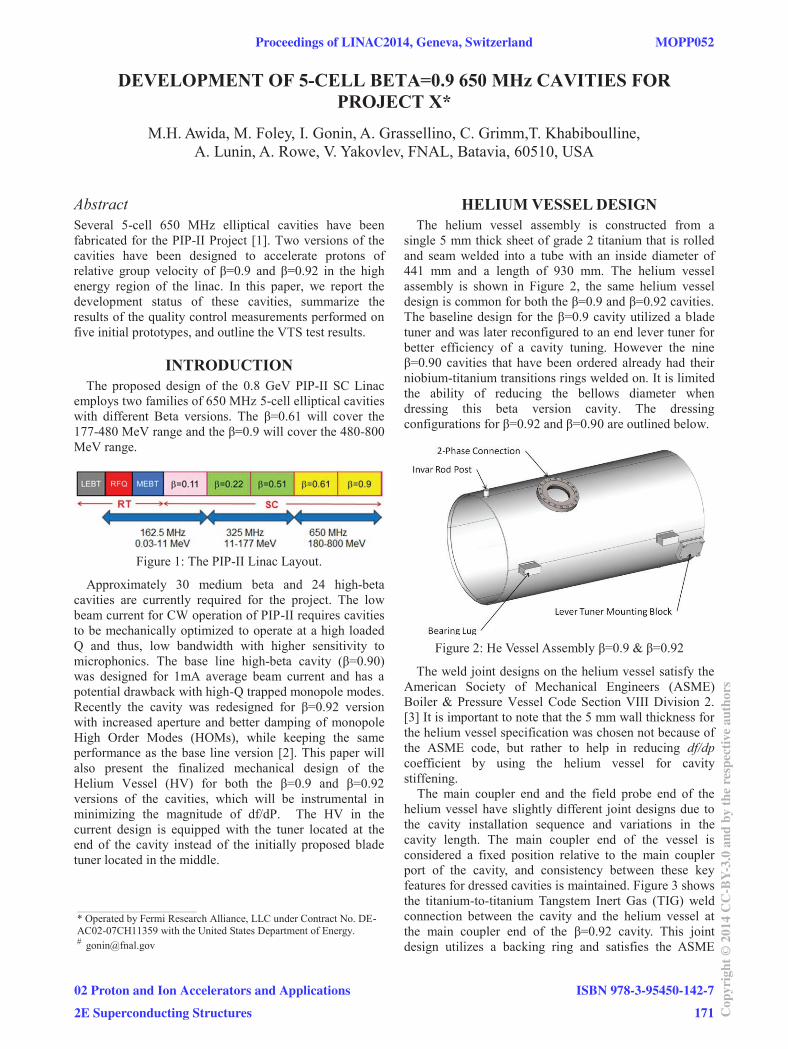
INTRODUCTION The proposed design of the 0.8 GeV PIP-II SC Linac
employs two families of 650 MHz 5-cell elliptical cavities with different Beta versions. The β=0.61 will cover the 177-480 MeV range and the β=0.9 will cover the 480-800 MeV range.
Figure 1: The PIP-II Linac Layout.
Approximately 30 medium beta and 24 high-beta cavities are currently required for the project. The low beam current for CW operation of PIP-II requires cavities to be mechanically optimized to operate at a high loaded Q and thus, low bandwidth with higher sensitivity to microphonics. The base line high-beta cavity (β=0.90) was designed for 1mA average beam current and has a potential drawback with high-Q trapped monopole modes. Recently the cavity was redesigned for β=0.92 version with increased aperture and better damping of monopole High Order Modes (HOMs), while keeping the same performance as the base line version [2]. This paper will also present the finalized mechanical design of the Helium Vessel (HV) for both the β=0.9 and β=0.92 versions of the cavities, which will be instrumental in minimizing the magnitude of df/dP. The HV in the current design is equipped with the tuner located at the end of the cavity instead of the initially proposed blade tuner located in the middle.
HELIUM VESSEL DESIGN The helium vessel assembly is constructed from a
single 5 mm thick sheet of grade 2 titanium that is rolled and seam welded into a tube with an inside diameter of 441 mm and a length of 930 mm. The helium vessel assembly is shown in Figure 2, the same helium vessel design is common for both the β=0.9 and β=0.92 cavities. The baseline design for the β=0.9 cavity utilized a blade tuner and was later reconfigured to an end lever tuner for better efficiency of a cavity tuning. However the nine β=0.90 cavities that have been ordered already had their niobium-titanium transitions rings welded on. It is limited the ability of reducing the bellows diameter when dressing this beta version cavity. The dressing configurations for β=0.92 and β=0.90 are outlined below.
Figure 2: He Vessel Assembly β=0.9 & β=0.92
The weld joint designs on the helium vessel satisfy the American Society of Mechanical Engineers (ASME) Boiler & Pressure Vessel Code Section VIII Division 2. [3] It is important to note that the 5 mm wall thickness for the helium vessel specification was chosen not because of the ASME code, but rather to help in reducing df/dp coefficient by using the helium vessel for cavity stiffening. The main coupler end and the field probe end of the helium vessel have slightly different joint designs due to the cavity installation sequence and variations in the cavity length. The main coupler end of the vessel is considered a fixed position relative to the main coupler port of the cavity, and consistency between these key features for dressed cavities is maintained. Figure 3 shows the titanium-to-titanium Tangstem Inert Gas (TIG) weld connection between the cavity and the helium vessel at the main coupler end of the β=0.92 cavity. This joint design utilizes a backing ring and satisfies the ASME
____________________________________________
* Operated by Fermi Research Alliance, LLC under Contract No. DE-AC02-07CH11359 with the United States Department of Energy. # [email protected]
Proceedings of LINAC2014, Geneva, Switzerland MOPP052
02 Proton and Ion Accelerators and Applications
2E Superconducting Structures
ISBN 978-3-95450-142-7
171 Cop
yrig
ht©
2014
CC
-BY-
3.0
and
byth
ere
spec
tive
auth
ors

code. Figure 4 illustrates the welding configuration at the main coupler end for the β=0.90 cavity.
Figure 3: He vessel to cavity fixed joint β=0.92
Figure 4: He vessel to cavity fixed joint β=0.9
In order to allow length variations of the manufactured cavities, the field probe end is required having a sliding joint design that would allow the cavity insertion from the field probe end to the main coupler end. As shown in Figures 5 and 6, cavities that vary by ±10 mm in length will not have any effect on the vessel design. This joint also satisfies the ASME code.
Figure 5: He vessel to cavity sliding joint design β=0.92
Figure 6: He vessel to cavity sliding joint design β=0.9
Dressed Cavity Pressure Boundary Where practical, the overall cavity design must adhere
to the ASME Boiler and Pressure Vessel Code. The pressure boundary will consist of the cavity walls, the connecting flanges, conical disks, and the helium vessel shell. This is outlined in Figure 7.
Figure 7: Pressure boundary of dressed cavity shown in yellow.
All electron-beam (EB) welds within the pressure boundary defined above are required to have a fully consumed joint: i.e. duel pass with full overlap or full penetration.
SINGLE-CELL CAVITIES A few prototypical β = 0.9 single-cell cavities are being
built to prove the cavity design and acquire experience in working with these new types of elliptical cavities. Six cavities were produced by Advanced Energy System (AES) and two of them have been tested at Vertical Test Stend (VTS). Six cavities were ordered from PAVAC Industries Company and two of them have already been delivered to Fermilab. Fig. 8 shows the set of AES cavities.
Figure 8: Six AES cavities complete in-house.
MOPP052 Proceedings of LINAC2014, Geneva, Switzerland
ISBN 978-3-95450-142-7
172Cop
yrig
ht©
2014
CC
-BY-
3.0
and
byth
ere
spec
tive
auth
ors
02 Proton and Ion Accelerators and Applications
2E Superconducting Structures

Figure 9: Summary of single cell cavities test.
Two cavities were tested at 2 K and they performed well above design requirements. First cavity B9AS_AES001 was tested three times: after EP, after additional 120C baking and after HF rinsing. The accelerating gradient reached 23-31 MV/m compared to the design specification of 17 MV/m. The quality factor at nominal accelerating gradient was 1.5 times higher than required. Some tests revealed noticeable field emission at operating gradient indicating surface cleaning issues. In two tests field emission diminished after high power processing. At 15 MV/m weak multipactoring was observed which processed away after power processing. 5-CELL CAVITIES
Figure 10: Two AES 5-cells cavities
Recently four 5-cell β=0.9 cavities were delivered from AES. They have been inspected for proper mechanical dimensions, RF performance, and prepared for eventual chemical processing. An additional five cavities are under production at PAVAC. Detailed HOM analysis of
the 5-cell cavity reveals trapped modes. Some modification of cavity geometry was done in order to increase coupling of these modes with the power coupler and reduce loaded Q values.
The goal of the cavity shape optimization is to minimize both surface electric Ep and magnetic Hp fields while achieving good coupling of the HOMs with the power coupler in order to reduce Qext. As a result of this analysis, the optimum profile of the end and mid cell were achieved, which is illustrated in Figure 11. A new version of the cavity for the High Energy section of the PIP-II Linac has a 120 mm aperture and a higher beta value of βgeom=0.92 [2]. The proposed high beta cavity provides good monopole HOM damping and thus assures reliable operation at high beam current.
Figure 11. Old (blue) and new (red) cell shapes.
SUMMARY The finalized mechanical design of the Helium Vessel
(HV) for both the β=0.9 and β=0.92 versions of the cavities has been done. A few prototypical β = 0.9 single-cell cavities are being built and successfully tested. Recently four 5-cell β=0.9 cavities were delivered from AES. They have been inspected for proper mechanical dimensions, RF performance, and prepared for eventual chemical processing.
REFERENCES [1] V. Lebedev, “PIP-II and PXIE”, PIP-II Meeting,
February 2014, Document 1260, Project X database. [2] Lunin, et al. "Alternative Cavity for H E Part of the
Project X linac." WEPPR019, Proceedings of IPAC 2012.
[3] https://www.asme.org/shop/standards/new-releases/boiler-pressure-vessel-code-2013/pressure-vessels
Proceedings of LINAC2014, Geneva, Switzerland MOPP052
02 Proton and Ion Accelerators and Applications
2E Superconducting Structures
ISBN 978-3-95450-142-7
173 Cop
yrig
ht©
2014
CC
-BY-
3.0
and
byth
ere
spec
tive
auth
ors