development of a cfd m for simulation sesss.com.br/events/ansys2013/brazil/pdf/24_5_1600.pdf ·...
TRANSCRIPT
DEVELOPMENT OF A CFD MODEL FOR
SIMULATION OF SELF-PROPULSION TESTS
Alexandre T. P. Alho
Laboratório de Sistemas de Propulsão
DENO/POLI, UFRJ

Motivation
▪ Growing demand for high efficiency propulsion systems.
▪ Demand for accurate power predictions in less time and at low costs.
Accurate CFD models: designers can rely on as an effective design tool.
CFD model must be developed based on a good compromise between
the quality of the numerical result and the computational effort.
▪ Numerical investigation of propeller-hull interaction.
Pitot-based experimental methods are virtually impossible.
Velocimetry methods still have challenges to overcome.
“Green” ship
Domain and grid configuration
Numerical models adopted
INTRODUCTION

Objective
▪ Develop a CFD model dedicated to estimate the propulsion factors
and to simulate the self-propulsion test of a hull.
Methodology
▪ The flow around a typical displacement hull, equipped with a
standard marine propeller, is simulated by means of commercial
CFD code (ANSYS CFX, release 14).
Focus
▪ Design applications.
INTRODUCTION

Displacement hull (Bulk carrier, CB = 0.86)
Twin screw propulsion system: 2 x B-Series propellers
Main Dimensions:
▪ Length (Loa): 73.4 m
▪ Length (Lpp): 70.6 m
▪ Breath (B): 14.8 m
▪ Design draught (T): 2.6 m
▪ Service Speed (VS): 9.5 knt
Shallow draught:
▪ Lower T/D ratio: 0.176 m
(0.35..0.48)
HULL PARTICULARS
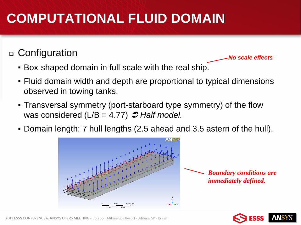
Configuration
▪ Box-shaped domain in full scale with the real ship.
▪ Fluid domain width and depth are proportional to typical dimensions
observed in towing tanks.
▪ Transversal symmetry (port-starboard type symmetry) of the flow
was considered (L/B = 4.77) Half model.
▪ Domain length: 7 hull lengths (2.5 ahead and 3.5 astern of the hull).
No scale effects
Boundary conditions are
immediately defined.
COMPUTATIONAL FLUID DOMAIN
Requirements
▪ CFD model as an effective design tool grid configuration must
minimize error sources and its propagation with less computational
load.
▪ Classical strategy: anisotropic meshes with a fine grid in directions of
high gradients of flow properties (relatively coarse mesh in other
directions).
Mesh Generation Approach: Hull (I)
▪ Displacement hulls: viscous and wave-making resistance are the
major resistance components a fine grid in the near-wall region of
the hull and a good discretization of the free surface must be
simultaneously implemented. Usually results in high
storage and runtime
requirements!!!
GRID CONFIGURATION

Mesh Generation Approach: Hull (II)
▪ Hull lines: predominantly flat surfaces viscous drag estimated
based on flat plate approach.
Non-structured mesh with a refinement
approach focused on the discretization
of the free surface: 2.7k tetra elements.
GRID CONFIGURATION

Mesh Generation Approach: Propeller (III)
▪ Non-structured mesh with fine refinement near leading and trailing
edges: 3.7k elements (tetra and prism).
GRID CONFIGURATION

RANS Code
▪ ANSYS CFX 14.
Flow Regime
▪ Steady state design applications.
Free Surface
▪ Volume of Fluid model (VOF):
Propeller
▪ Frozen rotor model
Turbulence Model
▪ Two-equation SST model with the scalable wall function approach.
0
iFu
t
F
NUMERICAL MODEL

Simulation of an Open Water Test
▪ Propeller: Series B, 4 blade, 1.4 m dia.
▪ N = 450 rpm; VA = 3.150, 3.675 and 4.200 m/s.
PROPELLER MODEL VALIDATION
VA =4.2 m/s

Hull+Propeller Curve
▪ Discrepancies: 8..10%
PROPELLER MODEL VALIDATION
0,00
0,05
0,10
0,15
0,20
0,25
0,30
0,35
0,00 0,10 0,20 0,30 0,40 0,50 0,60 0,70 0,80
KT,
10
KQ
J
KT (Exp)
10 KQ (Exp)
KT (CFD)
10 KQ (CFD)
High tangential velocities demand fine
grid refinement compromise between
quality and computational effort.

Hull Performance
▪ Test speed (VS): 9.5 knt
▪ Total resistance (RT): 50.6 kN
▪ Wake coefficient (w): 0.153
TOWING TEST SIMULATION

Test Results
▪ Propeller revolutions (N): 433 rpm
▪ Propeller thrust (Treq): 65.3 kN
SELF-PROPULSION TEST SIMULATION
N = 420 rpm

Results Evaluation
▪ Comparison against statistical estimation.
▪ Wake fraction, thrust deduction fraction and relative-rotative efficiency
predictions based on Holtrop & Mennen (1984).
SELF-PROPULSION TEST SIMULATION
Statistical Numerical Dif.
Propeller Revolutions 456 433 -5.2% rpm
Propeller Thrust 70.4 65.3 -7.8% kN
Wake Fraction 0.181 0.153 -16.7% ---
Thrust Deduction Fraction 0.243 0.184 -32.3% ---
Relative-rotative Efficiency 1.028 1.024 -0.4% ---

The overall performance achieved suggests that the numerical
model was able to resolve the physics of the flow related to
hull&propeller interaction at full scale.
The comparison against statistical predictions showed that:
▪ The numerical model was able to provide reasonable
predictions for propeller thrust and revolutions under self-
propulsion conditions.
▪ The numerical model was able to provide more realistic
predictions of the effects of hull&propeller interaction.
Future investigations are needed concerning the validation of
the numerical model against experimental data.
CONCLUSIONS