development of a dc-ac power conditioner for … · projek ini mempersembahkan fasa tunggal...
TRANSCRIPT

i
DEVELOPMENT OF A DC-AC POWER CONDITIONER FOR WIND GENERATOR BY USING FUZZY LOGIC
FAISEL MOHAMED JELWAL
A thesis submitted in
fulfillment of the requirement for the award of the
Degree of Master of Electrical Engineering
Faculty of Electrical and Electronic Engineering
Universiti Tun Hussein Onn Malaysia
MAY 2011

v
ABSTRACT
In this project, a fuzzy logic controller is designed to obtain the desired output voltage of
DC-AC power conditioner used in a stand alone wind generator which the Fuzzy Logic
Controller (FLC) is employed to control the modulation index of the SPWM (Sinusoidal -Pulse
Width-Modulation) inverter which is built using four MOSFET’s transistor. This project present
of development single phase DC-AC converter for wind generator application. The mathematical
model of the wind generator and Fuzzy Logic Controller for DC-AC converter is derived. The
controller is designed to stabilize the output voltage of DC-AC converter. To verify the
effectiveness of the proposal controller, both simulation and experimental are developed. The
simulation and experimental result show that the amplitude of output voltage of the DC-AC
converter can be controlled.

vi
ABSTRAK
Projek ini mempersembahkan fasa tunggal pembangunan penukar DC-AC untuk aplikasi
penjana angin. Model matematik penjana angin dan kawalan Fuzzy Logic Controller untuk
penukar DC-AC diterbitkan. Pengawal direka bagi memantapkan voltan keluaran penukar DC-
AC. Untuk mengesahkan keberkesanan pengawal cadangan, kedua-dua simulasi dan eksperimen
telah dibangunkan. Simulasi dan keputusan eksperimen menunjukkan bahawa amplitud voltan
keluaran penukar DC-AC boleh dikawal.

vii
LIST OF CONTENTS
THESIS STATUS CONFIRMATION
SUPERVISOR’S DECLARATION
TITLE PAGE i
DECLARATION ii
DEDICATION iii
ACKNOWLEDGEMENT iv
ABSTRACT v
ABSTRAK vi
TABLE OF CONTENTS vii
LIST OF TABLES x
LIST OF FIGURES xi
LIST OF ABBREVIATIONS AND ACRONYMS xiv
LIST OF APPENDICES xv
CHAPTER 1 INTRODUCTION 1
1.1 Background of study 1
1.2 Objective of Project 3
1.3 Problem Statement 3
1.4 Scope of Project 4
CHAPTER 2 LITERATURE REVIEW ON WIND TURBINE 5
2.1 Electrical Characteristics of a variable –speed wind
turbine
5
2.1.1 Wind turbine with gearbox 6
2.1.2 wind turbine without gearbox 7

viii
2.2 DC generator for the wind turbine 8
2.3 Characteristics of a small wind-power system with DC
generator
9
2.4 power control using speed variation 10
2.5 Modern power electronics in wind turbine systems 11
2.6 power conditioning 13
2.7 Pulse –width- modulation inverter 13
2.8 Fuzzy Controller 14
2.8.1 Useful cases 14
2.8.2 Advantages of FLC 14
2.9 construction of fuzzy controller 15
2.10 Gaussian Membership Functions 16
2.10.1 Characteristics of Gaussian method 16
2.11 Real-time F2808 eZdsp 17
2.12 DSP TMS 320F 2808 board 17
CHAPTER 3 METHODOLOGY 19
3.1 Research Design 19
3.1.1 System Description 21
3.1.2 Single phase bridge inverter 21
3.1.2.1 Inverter circuit using Matlab Simulink 22
3.1.3 Control Strategies of Sinusoidal PWM waveforms 23
3.1.3.1 SPWM generating using C++ programming by Matlab
Simulink
24
3.1.4 FLC Strategies 25
3.2 The proposed design for power conditioner (fuzzy logic
controller).
25
3.2.1 Fuzzy logic controller by FL tool box 26
3.2.2 Fuzzy logic controller by C++ programming 29
3.3 Hardware design and connection 30
3.3.1 Download SPWM switching from Real Time Matlab into DSP board.
31

ix
3.3.2 Design and connecting PCB inverter circuit and driver
circuits
31
3.3.3 Connecting parts of the hardware 32
CHAPTER 4 RESULT AND ANALYSIS 33
4.1 Introduction 33
4.2 Results of simulation 33
4.2.1 Results of Matlab simulation 34
4.2.2 Hardware simulation results 38
CHAPTER 5 CONCLUSION AND RECOMMENDATION 41
5.1 Conclusions 41
5.2 Recommendation 42
REFERENCES 43
APPENDICES A-C 44-69

xi
LIST OF FIGURES
2.1
Showing electric power as a function of rotor speed with
curves and curves of same wind speed
6
2.2 Wind turbine with gearbox 7
2.3 Wind turbine without gearbox 8
2.4 Influence on the field current for variable wind speed
(P1>P2>P3>P4).
9
2.5 Power electronic system with the grid, load/source, power
converter and control.
11
2.6 Developments of power semiconductor devices in the past and
in the future which are used in wind energy technology.
12
2.7 Diagram of fuzzy controller 14
2.8 Fuzzy Controller Block Diagram 15
2.9 Gaussian Membership Functions 16
2.10 F2808 DSP board 18
3.1 Flow chart of project 20
3.2 Synoptic system of wind turbine 21
3.3 Single-phase full-bridge inverter 22
3.4 The waveforms for the inverter output 22
3.5 Flowchart of processing inverter circuit using Matlab Simulink 23
3.6 SPWM and inverter output voltage 24

xii
3.7 Stages to control the inverter output 26
3.8 Block diagram of fuzzy logic process 26
3.9 Membership function for error 27
3.10 Membership function for change of error 27
3.11 Membership function for fuzzy logic control 28
3.12 Flowchart of fuzzy logic controller by C++ programming 29
3.13 Flow chart of stages of hardware design 30
3.14 Shows F2808 eZdsp block with complete system to generate SPWM C code into DSP board.
31
4.1 Fuzzy logic controller circuits 34
4.2 Input SPWM pulse for MOSFIT’s switches 35
4.3 Unfiltered output inverter of resistive load for modulation index0.7858.
36
4.4 Output waveforms of DC-AC power conditioner simulation 36
4.5 Output waveforms of DC-AC power conditioner simulation by
C++
37
4.6 Hardware testing session 39
4.7 Unipolar SPWM output signals
39
4.8 Output voltages for (mi) of 0.7924 (a) & (b) Unfiltered output 40

x
LIST OF TABLES
3.1 Fuzzy rule table 28
4.1 comparison between Ref-voltage, output voltage and output
of FLC
37
4.2 comparison between Ref-voltage, output voltage using C++
program
38

`xv
LIST OF APPENDICES
A Matlab Simulation 44
B C++ Programming 46
C Hardware wiring 69
xiv
LIST OF ABBREVIATIONS AND ACRONYMS
DC - Direct Current
AC - Alternate Current
SPWM - Sinusoidal Pulse Width Modulation
MATLAB - Matrix Laboratory
DSP - Digital signal Processes
FLC - Fuzzy Logic Controller
SIMULINK - Simulation and Link
IGPT - Insulated Gate Bipolar Transistor
MOSFET - Metal Oxide Semiconductor Field-Effect Transistor
VDC - Voltage Direct Current
Vr - Voltage Reference
Vo - Voltage output
Vc - Voltage Carrier
Mi - Modulation Index
PCB - Printed Circuit Board
E - Error
DE - Delta Error
MF - Member Function
WECS - Wind Energy Conversion Systems

CHAPTER 1
INTRODUCTION
1.1 Background of Study
Nowadays, a large interest to power the world with clean energy has become
a world target. This has motivated all researchers to redirect their work into the
renewable energy source. Wind turbine is considered as one of the targeted clean
energy source. Wind turbines are electromechanical devices that convert the wind
energy into electrical energy. The wind turbine is mix and match a variety of
innovation concepts with proven technologies both generators and power electronics
(Thomas Ackermann, 2005).
There are several types of design of wind turbines generators; which is either
AC or DC generators, such as “AC generators (induction- asynchronous) and DC
generators (shunt wound-series wound)”.Output of wind generator depends on wind
speed therefore to maintain the output voltage a power conditioning is required
(Thomas Ackermann, 2005).

2
The power conditioners must have the following specifications:
High gain, to contribute to energy conservation in the form of various
products, ranging from a lot of appliances.
Small current ripple.
High efficiency and low cost ( Hongzhong Ma et al.; 2009).
The DC-AC power conditioners are equipments that generate wind power by
converting direct current, supplied by generator of wind turbine, into alternating
current. In this power conditioner, the electric energy, generated by DC generator
which is driven by the wind turbine, changes into qualified AC energy by DC-AC
inverter. An inverter (DC-AC with controllable frequency and voltage) to covert
direct current into alternating current, while the energy flows to the AC side
(Hongzhong Ma et al.; 2009).At the same time, the storage battery, mounted between
the output of the DC generator and the SPWM inverter, can compensate the voltage
variation caused by variable wind speed by charge-discharge in a small range to keep
the output power constant
The pulse width- modulated (PWM) DC-AC inverter has been the main choice in
power electronics for deadest, because of its circuit simplicity and rugged control
scheme. Modulation techniques are used in inverter to regulate output voltage/current
by using IGBT inverter. The pulse width modulation technique decides the switching
losses in the inverter, harmonic contents in output waveform, and overall
performance of the inverter. Sine wave pulse width modulation (SPWM) is most
widely used scheme due to its simplicity and better output profile (Maria D.
Bellar,1998).
In consideration of the characteristics of wind power system and DC generator, a
wind power generation in this system based on DC generator with DC-AC power
conditioner are developed, which consists of a variable pitch wind turbine, an
adjustable excitation DC generator, which a SPWM inverter with low-frequency
parts and some other related control parts. The main task of wind turbine control

3
system is enabling continuous power production under all operating conditions
determined by various wind speeds (Thomas Ackermann, 2005).
As output power is directly proportional to generator speed, power control can be
done by controlling generator speed or by controlling inverter SPWM by using fuzzy
logic controller as an alternative approach to wind turbine modeling is proposed in
this system.
1.2 Objective of Project.
Develop simulation model of DC-AC power conditioner for wind generator
Using MATLAB of Fuzzy Logic controller for DC-AC power conditioner
Develop single phase DC-AC power conditioner using Mosfet
semiconductor.
1.3 Problem Statement.
Due to the volatility and the uncontrollability of wind source, hence output power
of a wind generator become unstable. By this reason a variable speed wind energy
systems integrated with power electronic interfaces are becoming popular because it
can extract maximum power from the wind and maintain constant output. In this
project the problem statements are how to develop simulation model of inverter,
sinusoidal PWM and Fuzzy Logic Controller (FLC).also how to develop single phase
inverter circuit wiring Mosfet and SPWM program in DSP board

4
1.4 Scope of Project.
This project is primarily concerned with development of (DC-AC) power
conditioner for wind generator. The scopes of this project are:-
Modeling of a DC wind generator, DC-AC converter and Fuzzy Logic
Controller are simulating using MATLAB.
Sinusoidal Pulse Width Modulation (SPWM) technique is used to control the
switching signals for the DC-AC power inverter
Using neural Fuzzy Logic technique as controller to improve performance of
power conditioner for system
The controller and (SPWM) develop in DSP Board

CHAPTER 2
LITERATURE REVIEW ON WIND TURBINE
2.1 Electrical Characteristics of a variable –speed wind turbine
Variable–speed turbines are designed to achieve maximum aerodynamic
efficiency over a wide range of wind speeds. With variable –speed operation it has
become possible continuously to adapt (accelerate or decelerate) the rotational speed
ω of the wind turbine to the wind speed υ. This way, the tip speed ratio γ is kept
constant at a predefined value that corresponds to the maximum power coefficient
the relationship between a variable – speed wind turbine generator and output power
is described in figure 2.1(Thomas Ackermann,2005).
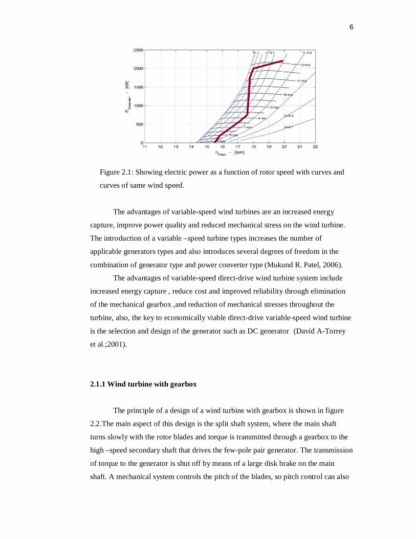
6
Figure 2.1: Showing electric power as a function of rotor speed with curves and
curves of same wind speed.
The advantages of variable-speed wind turbines are an increased energy
capture, improve power quality and reduced mechanical stress on the wind turbine.
The introduction of a variable –speed turbine types increases the number of
applicable generators types and also introduces several degrees of freedom in the
combination of generator type and power converter type (Mukund R. Patel, 2006).
The advantages of variable-speed direct-drive wind turbine system include
increased energy capture , reduce cost and improved reliability through elimination
of the mechanical gearbox ,and reduction of mechanical stresses throughout the
turbine, also, the key to economically viable direct-drive variable-speed wind turbine
is the selection and design of the generator such as DC generator (David A-Torrey
et al.;2001).
2.1.1 Wind turbine with gearbox
The principle of a design of a wind turbine with gearbox is shown in figure
2.2.The main aspect of this design is the split shaft system, where the main shaft
turns slowly with the rotor blades and torque is transmitted through a gearbox to the
high –speed secondary shaft that drives the few-pole pair generator. The transmission
of torque to the generator is shut off by means of a large disk brake on the main
shaft. A mechanical system controls the pitch of the blades, so pitch control can also

7
be used to stop the operation of the converter, in stormy conditions. The pitch
mechanism is driven by a hydraulic system, with oil as the popular medium. For
construction without a main brake, each blade has its pitch angle controller by a
small electric motor. The gearbox concept was in many cases accompanied by an
insufficient life time because of failure of gearbox (Hermann-Josef wanger et al.;
2010).
Figure: 2.2: wind turbine with gearbox (wind system, 2010)
2.1.2 Wind turbine without gearbox
The main idea for this design depends on another converter type without
gearbox is shown in Fig 2.3. This design has adjusted one stationary shaft .The rotor
blades and the generator is both mounted on this shaft. The multi-pole generator is in
the form of a large spoked wheel with. Forty-tow pole pairs around the outer
circumference and stators mounted on a stationary arm around the wheel. The wheel
is fixed to the blade apparatus, so it rotates slowly with the blades. Therefore, there is
no need for a gearbox, rotating shafts or a disk brake. This minimizing of rotating
parts reduces maintenance and failure possibilities and simplifies the maintenance
and production of the converter. The price for these advantages is a high nacelle
mass caused by the high copper content of multi-pole generator (Hermann-Josef
wanger et al.; 2010).

8
Figure 2.3: wind turbine without gearbox (wind system, 2010)
2.2 DC generator for the wind turbine
The DC generator converts the inside AC into DC for outside use. It does so
by using a mechanical commutator. It switches the positive output terminal
continuously to the conductor generating the positive polarity voltage, and likewise
for the negative polarity terminal which the sliding contacts inherently result in low
reliability (Muhammad H.Rashid, 2006). Despite this disadvantage, the DC generator
use in a limited numbers of wind power installation of a small capacity. Figure 2.4
shows the curves of the relationship between the required field current and the
rotation speed of the variable wind turbine.
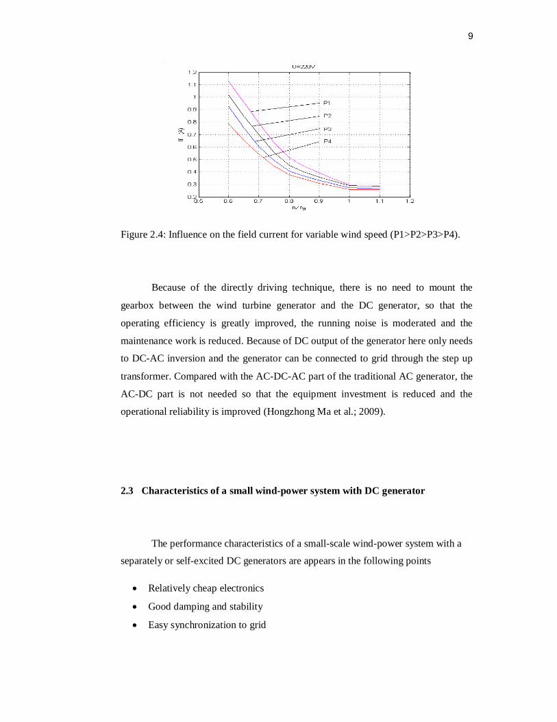
9
Figure 2.4: Influence on the field current for variable wind speed (P1>P2>P3>P4).
Because of the directly driving technique, there is no need to mount the
gearbox between the wind turbine generator and the DC generator, so that the
operating efficiency is greatly improved, the running noise is moderated and the
maintenance work is reduced. Because of DC output of the generator here only needs
to DC-AC inversion and the generator can be connected to grid through the step up
transformer. Compared with the AC-DC-AC part of the traditional AC generator, the
AC-DC part is not needed so that the equipment investment is reduced and the
operational reliability is improved (Hongzhong Ma et al.; 2009).
2.3 Characteristics of a small wind-power system with DC generator
The performance characteristics of a small-scale wind-power system with a
separately or self-excited DC generators are appears in the following points
Relatively cheap electronics
Good damping and stability
Easy synchronization to grid

10
With the converter as rectifier, the dc .machine may be run as a motor (useful
for starting vertical axis machines).
Electronics limit the fault level. (L.L.Freris, 1990).
That the maximum output is proportional to the cube of the wind speed and
consequently the field current (or the load resistance) must be controlled over
a wide wind speed range to obtain maximum output power (T. Suzuki et al.;
1982).
2.4 power control using speed variation
1. When the frequency is constant, the speed of a wind turbine can be
influenced as allows:
Mechanically by varying the transmission ratio if the generator speed is
constant.
Electronically by frequency converter if the speed is rotation is variable
over the entire drive train (turbine, gearing, and generator).
The turbine speed can thus be adapted to meet operational requirements.
Varying the rotor speed in turn varies the power of the turbine, allowing it
To be brought into the maximum range, depending on available wind, or
To be reduced if required meeting user requirements.
Currently used power electronics (rectifiers, commutated inverters) to convert
the frequency to that required (Siegfried Heier,2006).
2. When there is flexible coupling for grid or equipments are employed, the
effect Fluctuations in available wind can be reduced by making use of the
rotating Mass of the drive train to:
smooth out variations in rotor speed and reduce the dynamic load on
the entire system.

11
In this way, the power converter allows a very Short- time intervention at the
generator, which allows the requirements and desired to be achieved at the turbine
via the drive train (Siegfried Heier, 2006).
2.5 Modern power electronics in wind turbine systems
The wind turbine behavior/performance is very much improved by using
power electronics. They are able to act as a contributor to the frequency and voltage
control. Also it can be concluded the power scaling of wind turbines is important in
order to be able to reduce the energy cost.
Power electronics has changed rapidly during the last thirty years and the number of
applications has been increasing, mainly due to the developments of the
semiconductor devices and the microprocessor technology. For both cases higher
performance is steadily given for the same area of silicon, and at the same time they
are continuously reducing the price. Figure 2.5 shows a typical power electronic
system consisting of a power converter, a load/source and a control unit as in wind
turbine system (F. Blaabjerg, 2006).
Figure 2.5: power electronic system with the grid, load/source, power converter and
control. (F. Blaabjerg, 2006).
The power converter is the interface between the load/generator and the grid.
The power may flow in both directions, of course, dependent on topology and
12
applications. Three important issues are of concern using such a system. The first one
is reliability; the second is efficiency and the third one is cost. For the moment the
cost of power semiconductor devices is decreasing 2-5 % every year for the same
output performance and the price pr. kW for a power electronic system is also
decreasing. The key driver of this development is that the power electronic device
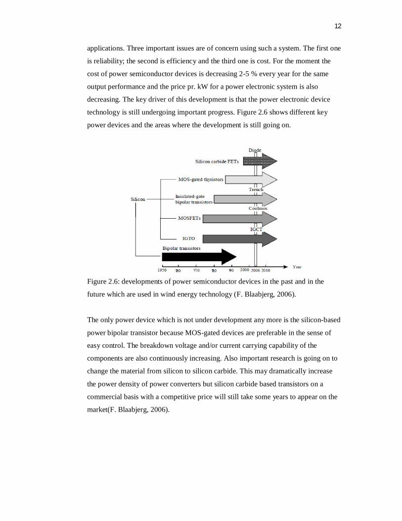
technology is still undergoing important progress. Figure 2.6 shows different key
power devices and the areas where the development is still going on.
Figure 2.6: developments of power semiconductor devices in the past and in the
future which are used in wind energy technology (F. Blaabjerg, 2006).
The only power device which is not under development any more is the silicon-based
power bipolar transistor because MOS-gated devices are preferable in the sense of
easy control. The breakdown voltage and/or current carrying capability of the
components are also continuously increasing. Also important research is going on to
change the material from silicon to silicon carbide. This may dramatically increase
the power density of power converters but silicon carbide based transistors on a
commercial basis with a competitive price will still take some years to appear on the
market(F. Blaabjerg, 2006).
13
2.6 power conditioning
Power conditioning, as well as energy conversion, represented a decisive
milestone in the development of wind energy technology. In the 1980s, only high-
output pilot energy were constructed and operated as variable-speed units.
Development progressed from the cheap six-pulse converters with thyristors through
quasi-twelve-pulse circuits to the called pulse-controlled converters with
semiconductors switches operating in the kilohertz range.
This type of system also requires a converter system that is capable of conditioning
the variable-frequency electrical energy from the wind turbine generator for supply
to a lot of equipments of constant frequency and voltage (T. Suzuki et al.; 1982).
2.7 Pulse –width- modulation inverter
DC-AC converters are known as inverter. The function of an inverter is to
change a dc input voltage to a symmetric ac output voltage of desired magnitude and
frequency. It has a following Characteristic:
The output voltage could be fixed or variable at a fixed or variable
frequency.
A variable output voltage can be obtained by varying the input dc voltage
and maintaining the gain of the inverter constant.
If the dc input voltage is fixed and it isn’t controllable, a variable output
voltage can be obtained by varying the gain of the inverter.
The control of output voltage is normally accomplished by (PWM)
control within inverter.
The waveforms of practical inverters are no sinusoidal and contain
harmonics.
Each type of inverter can use controlled turn-on and turn-off devices such
as: metal oxide semiconductor field-effect transistors [MOSFETs], and
insulated-gate bipolar transistor [IGBTs] (Muhammad H.Rashid 2006).

14
2.8 Fuzzy Controller
Fuzzy control provides a formal methodology for representing, manipulating,
and implementing a human’s heuristic knowledge about how to control a system.
Figure 2.7: diagram of fuzzy controller
2.8.1 Useful cases
The control processes are too complex to analyze by conventional
quantitative techniques.
The available sources of information are interpreted qualitatively, inexactly,
or uncertainly (P. Siarry & F. Guely, 1998).
2.8.2 Advantages of FLC
Parallel or distributed control multiple fuzzy rules – complex nonlinear
system
Linguistic control. Linguistic terms - human knowledge
Robust control. More than 1 control rules – an error of a rule is not fatal
(P. Siarry & F. Guely, 1998).

15
2.9 construction of fuzzy controller
Most commercial fuzzy products are rule-based systems that receive current
information in the feedback loop from the device as it operates and control the
operation of a mechanical or other device (P. Siarry & F. Guely, 1998). A fuzzy
logic system has four blocks. Crisp input information from the device is converted
into fuzzy values for each input fuzzy set with the fuzzification block. The universe
of discourse of the input variables determines the required scaling for correct per-unit
operation. The scaling is very important because the fuzzy system can be retrofitted
with other devices or ranges of operation by just changing the scaling of the input
and output. The decision-making-logic determines how the fuzzy logic operations are
performed (Sup-Min inference), and together with the knowledge base determine the
outputs of each fuzzy IF-THEN rules. Those are combined and converted to crispy
values with the defuzzification block. The output crisp value can be calculated by the
center of gravity or the weighted average. Figure 2.8 Fuzzy Controller Block
Diagram.
Figure 2.8: Fuzzy controller block diagram (P. Siarry & F. Guely, 1998).

16
22.10 Gaussian Membership Functions a
N
Fuzzy membership function as shown in figure 2.9 that is of- ten used to
represent vague, linguistic terms is the Gaussian which is given by:
Where ci and _i are the centre and width of the ith fuzzy set Ai, respectively.
Figure 2.9 :Gaussian Membership Functions (personal.rdg.ac.uk)
2.10.1 Characteristics of Gaussian method
• Local although not strictly compact
• The output is very smooth
• Not probability
• Multivariate Gaussian functions can be formed from the product of the univariate
sets.

17
• Gaussian fuzzy membership functions are quite popular in the fuzzy logic
literature, as they are the basis for the connection between fuzzy systems and
radial basis function (RBF) neural networks (personal.rdg.ac.uk).
2.11 Real-time F2808 eZdsp
Real-Time Workshop generates and executes stand-alone C code for
developing and testing algorithms modeled in Simulink and Embedded MATLAB™
code. The resulting code can be used for many real-time and non-real-time
applications, including simulation acceleration, rapid prototyping, and hardware-in-
the-loop testing. Through real-time technology can tune and monitor the generated
code using Simulink blocks and built-in analysis capabilities, or run and interact with
the code outside the MATLAB and Simulink environment.
Options on the block mask allow setting features of code generation for Spectrum
Digital F2808 eZdsp target. Adding this block to Simulink model provides access to
building, linking, compiling, and targeting settings it needs to configure the code that
Real-Time Workshop generates (mathworks, 2011).
2.12 DSP TMS 320F 2808 board
The TMS2808 DSP Controller Board is designed around the fast state-of-the-
art digital signal processor (DSP) TMS320F2808 from Texas Instruments. This DSP
is designed using high-performance static CMOS technology allowing operation at
100 MHz in the temperature range from -40C to 125C. This DSP has a 32-bit high
performance CPU allowing 16 X 16, 32 X 32 MAC operations as well as 16 X 16
dual MAC operations. It has HARVARD bus architecture with atomic operation, fast
interrupt response and processing and a unified memory programming model. The
DSP chip has a watchdog timer module, a powerful peripheral interrupt expansion
(PIE) block that supports all 43 peripheral interrupts. It also has a 128-Bit security
key/lock which protects Flash/OTP/L0/L1 memory blocks and prevents firmware
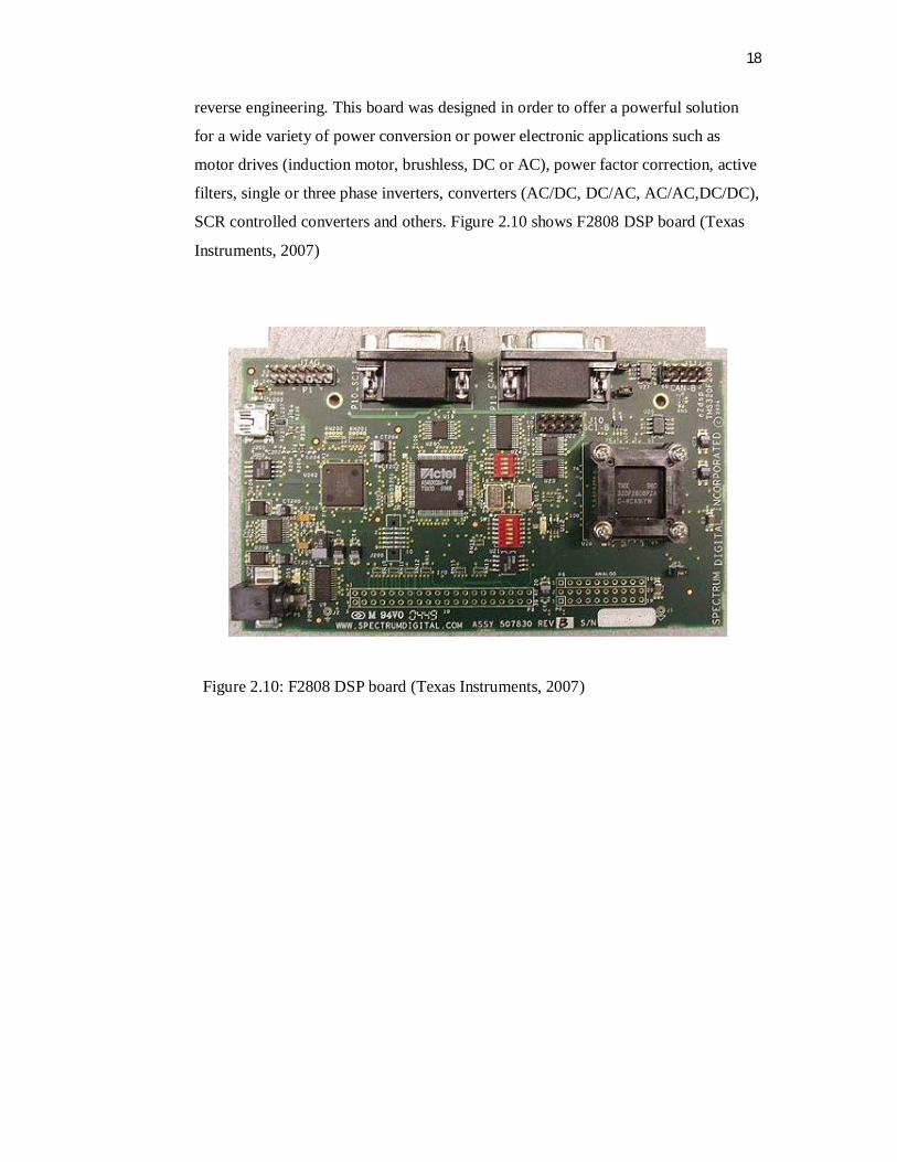
18
reverse engineering. This board was designed in order to offer a powerful solution
for a wide variety of power conversion or power electronic applications such as
motor drives (induction motor, brushless, DC or AC), power factor correction, active
filters, single or three phase inverters, converters (AC/DC, DC/AC, AC/AC,DC/DC),
SCR controlled converters and others. Figure 2.10 shows F2808 DSP board (Texas
Instruments, 2007)
Figure 2.10: F2808 DSP board (Texas Instruments, 2007)
CHAPTER 3
METHODOLOGY
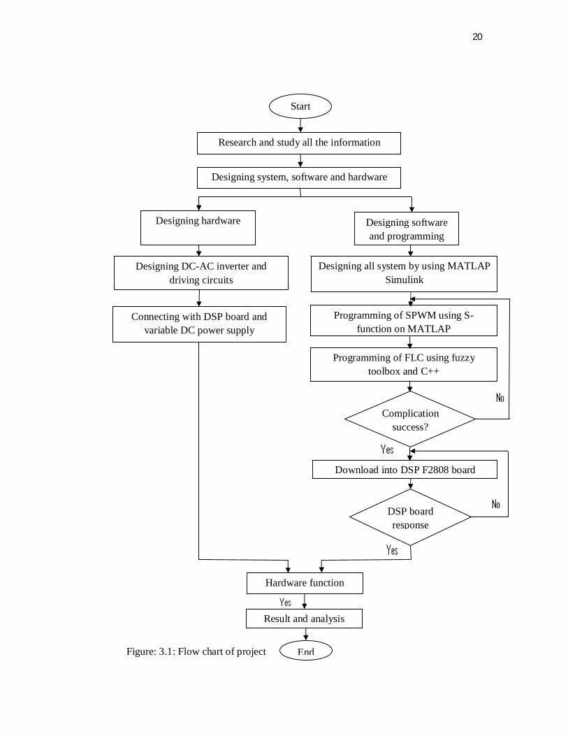
3.1 Research Design
To ensure access to electrical energy with a constant voltage is suitable for
many purposes that their source is variable speed wind energy, this is done using
single-phase inverter DC-AC controlled by the Fuzzy logic controller, without the
use of control the speed of turbine generator. The work is beginning with the
discussion of project title, objective and scope followed by seeking the information
for literature review and the time schedule arrangement. Literature review in the
previous chapter presents the characteristics of all system of wind turbine using as
standalone generator, and it shows importance using the power electronics in
application of wind turbine, also it explained using the fuzzy logic controller to
control the output of wind turbine instead of gearbox which is the fuzzy logic
controller widely used for process control in industries. This project presents a rule-
based fuzzy logic controller to control the output power of a sinusoidal pulse width
modulated (SPWM) inverter used in standalone wind energy. The Obtained
experimental and simulation results show the effectiveness of the proposed fuzzy
logic controller. The implementation of this project is based on the approach to
design and develop a (SPWM) DC-AC inverter and FLC for output voltage control.
The design details of the terms which are related to the fuzzy logic controller are
discussed in this section. Figure 3.1 shows the overview of the methodology flow
chart of this project.
20
y
Figure: 3.1: Flow chart of project
Start
Research and study all the information
Designing system, software and hardware
Designing software and programming
Designing hardware
Designing all system by using MATLAP Simulink
Programming of SPWM using S-function on MATLAP
Programming of FLC using fuzzy toolbox and C++
Complication success?
Download into DSP F2808 board
DSP board response
Designing DC-AC inverter and driving circuits
Connecting with DSP board and variable DC power supply
Hardware function
Result and analysis
End
21
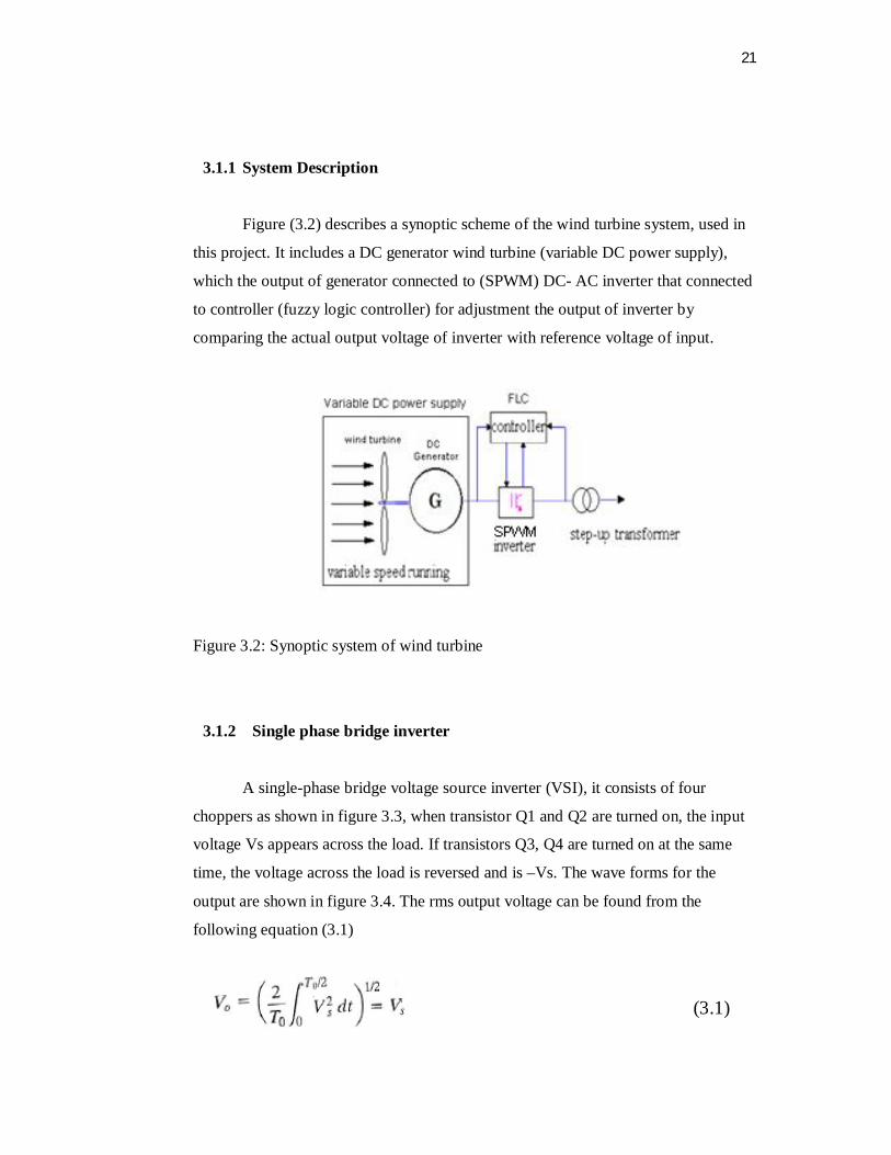
3.1.1 System Description
Figure (3.2) describes a synoptic scheme of the wind turbine system, used in
this project. It includes a DC generator wind turbine (variable DC power supply),
which the output of generator connected to (SPWM) DC- AC inverter that connected
to controller (fuzzy logic controller) for adjustment the output of inverter by
comparing the actual output voltage of inverter with reference voltage of input.
D
Figure 3.2: Synoptic system of wind turbine
3.1.2 Single phase bridge inverter
A single-phase bridge voltage source inverter (VSI), it consists of four
choppers as shown in figure 3.3, when transistor Q1 and Q2 are turned on, the input
voltage Vs appears across the load. If transistors Q3, Q4 are turned on at the same
time, the voltage across the load is reversed and is –Vs. The wave forms for the
output are shown in figure 3.4. The rms output voltage can be found from the
following equation (3.1)
(3.1)

22
Figure 3.3: Single-phase full-bridge inverter
Figure 3.4: waveform for the inverter output
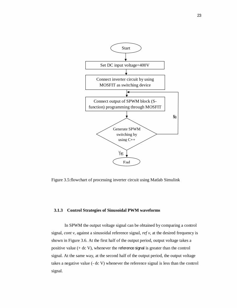
3.1.2.1 Inverter circuit using Matlab Simulink
Single phase full bridge inverter only consists of four arrangements of power
switches .Transistor MOSFIT 530N is used as a power switch in this project. The DC
input voltage is set to 400 volt dc for the entire inverter (refers APPENDEIX A). The
four output signals form SPWM programming block is directly connected to
MOSFIT’s gate terminal. The process of inverter circuit is shown in flowchart 3.5
23
Figure 3.5:flowchart of processing inverter circuit using Matlab Simulink
3.1.3 Control Strategies of Sinusoidal PWM waveforms
In SPWM the output voltage signal can be obtained by comparing a control
signal, cont v, against a sinusoidal reference signal, ref v, at the desired frequency is
shown in Figure 3.6. At the first half of the output period, output voltage takes a
positive value (+ dc V), whenever the reference signal is greater than the control
signal. At the same way, at the second half of the output period, the output voltage
takes a negative value (- dc V) whenever the reference signal is less than the control
signal.
Start
Set DC input voltage=400V
Connect inverter circuit by using MOSFIT as switching device
Connect output of SPWM block (S-function) programming through MOSFIT
Generate SPWM switching by using C++
End

24
The control frequency cont f determines the number of pulses per half of
cycle for the output voltage signal. Also, the output frequency Of is determined by
the reference frequency ref f. The modulation index Ma is defined as the ratio
between the sinusoidal magnitude and the control signal magnitude (Muhammad
H.Rashid,2006).
To obtain a vary train of pulses, each pulse has to vary proportional to the
necessary fundamental component precisely at the time when this pulse occurs. The
frequency of the output waveform needs to be higher than the frequency of the
fundamental component. By varying the width of each pulse, the inverter is able to
produce different levels of output voltage for the corresponding pulse event.
Figure 3.6: SPWM and inverter output voltage
3.1.3.1 SPWM generating using C++ programming by Matlab Simulink
The SPWM generator should be able to produce output frequency of 50 Hz and
generate pulses of SPWM switching signal per complete cycle. The modulation

43
REFERENCES
[1] Thomas Ackermann " wind power in power systems " 2005.
[2] Hongzhong Ma, Lin Chen, Ping Ju, Haihua Liu, Ning Jiang and Chunning
Wang, "Feasibility Research on DC Generator Based Wind Power Generation
System" , IEEE international conference o. 6.7 April 2009.
[3] Maria D. Bellar, Student Member, IEEE, Tzong-Shiann Wu, Member, IEEE,
Aristide Tchamdjou, Student Member, IEEE, Javad Mahdavi, Senior Member,
IEEE, and M. Ehsani, Fellow, IEEE,"A Review of Soft-Switched DC–AC
Converters". IEEE transaction on industry application, vol.34.no.4, July/august
1998.
[4] Mukund R. Patel"wind and solar power systems ", second edition, 2006.
[5] david A-Torrey , Sussan E-childs, Sjoerd de Hann "a variable-speed wind
turbine based on a direct –drive avariable- reluctance generator",IEEE.
[6] Hermann-Josef wanger, Yotirmay mathur ."Introduction to wind energy
systems(Basics,Technology and Operation). Second edition 2010.
[7] Muhammad H.Rashid" Power Electroics",circuits,devices,adapplication,third
edition,2006.
[8] L.L.Freris "Wind energy conversion systems" 1990.
[9] T. Suzuki, Ph.D., H. Okitsu, Ph.D., and T. Kawahito" Characteristics of a small
wind-power system with DC generator", IEEE PROC, Vol. 129, Pt. B, No. 4,
JULY 1982.
[10] Siegfried Heier "Grid Integration of Wind Energy Conversion Systems",
. second edition, 2006.

44
[11] F. Blaabjerg , Chen, R.Teodorescu ,F.lov "Power Electronics in wind turbine .
[12] P. Siarry, F. Guely, Fuzzy Sets Syst. 99 (1) (1998) 37–47.
[13] www.personal.rdg.ac.uk.
[14] www.mathworks.com.
[15] (Texas Instruments) www.focus.ti.com .
[16] (Wind systems) www. windsystemsmag.com.