development of a flexible injection moulding process for ... · pdf filedevelopment of a...
TRANSCRIPT

Development of a flexible injection moulding process forintegrated productsSchouenberg, M.J.F.H.
Published: 01/01/1993
Document VersionPublisher’s PDF, also known as Version of Record (includes final page, issue and volume numbers)
Please check the document version of this publication:
• A submitted manuscript is the author's version of the article upon submission and before peer-review. There can be important differencesbetween the submitted version and the official published version of record. People interested in the research are advised to contact theauthor for the final version of the publication, or visit the DOI to the publisher's website.• The final author version and the galley proof are versions of the publication after peer review.• The final published version features the final layout of the paper including the volume, issue and page numbers.
Link to publication
Citation for published version (APA):Schouenberg, M. J. F. H. (1993). Development of a flexible injection moulding process for integrated products.(DCT rapporten; Vol. 1993.184). Eindhoven: Technische Universiteit Eindhoven.
General rightsCopyright and moral rights for the publications made accessible in the public portal are retained by the authors and/or other copyright ownersand it is a condition of accessing publications that users recognise and abide by the legal requirements associated with these rights.
• Users may download and print one copy of any publication from the public portal for the purpose of private study or research. • You may not further distribute the material or use it for any profit-making activity or commercial gain • You may freely distribute the URL identifying the publication in the public portal ?
Take down policyIf you believe that this document breaches copyright please contact us providing details, and we will remove access to the work immediatelyand investigate your claim.
Download date: 10. May. 2018

Development of a FlexibleInjection Moulding Processfor Integrated Products
M.J.F.H. Schouenberg
Eindhoven University of TechnologyWFW 93.184December 1993

Contents
1 Introduction I
2 Existing injection moulding processes 3
3 Numerical simulations 6
4 Design of the accumulator 8
5 Making the preform 10Considerations for making the preform 10New technologies 12experimental 12
6 Results 14
7 Conclusions and recommendations 15
8 Literature 16
1 Introduction
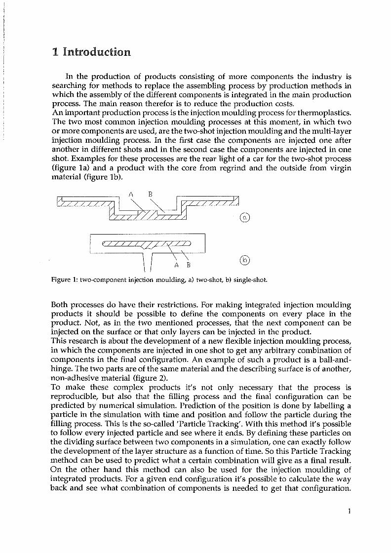
In the production of products consisting of more components the industry issearching for methods to replace the assembling process by production methods inwhich the assembly of the different components is integrated in the main productionprocess. The main reason therefor is to reduce the production costs.An important production process is the injection moulding process for thermoplastics.The two most common injection moulding processes at this moment, in which twoor more components are used, are the two-shot injection moulding and the multi-layerinjection moulding process. In the first case the components are injected one afteranother in different shots and in the second case the components are injected in oneshot. Examples for these processes are the rear light of a car for the two-shot process(figure Ia) and a product with the core from regrind and the outside from virginmaterial (figure ib).
Both processes do have their restrictions. For making integrated injection mouldingproducts it should be possible to define the components on every place in theproduct. Not, as in the two mentioned processes, that the next component can beinjected on the surface or that only layers can be injected in the product.This research is about the development of a new flexible injection moulding process,in which the components are injected in one shot to get any arbitrary combination ofcomponents in the final configuration. An example of such a product is a ball-and-hinge. The two parts are of the same material and the describing surface is of another,non-adhesive material (figure 2).To make these complex products it’s not only necessary that the process isreproducible, but also that the filling process and the final configuration can bepredicted by numerical simulation. Prediction of the position is done by labelling aparticle in the simulation with time and position and follow the particle during thefilling process. This is the so-called ‘Particle Tracking’. With this method it’s possibleto follow every injected particle and see where it ends. By defining these particles onthe dividing surface between two components in a simulation, one can exactly followthe development of the layer structure as a function of time. So this Particle Trackingmethod can be used to predict what a certain combination will give as a final result.On the other hand this method can also be used for the injection moulding ofintegrated products. For a given end configuration it’s possible to calculate the wayback and see what combination of components is needed to get that configuration.
Figure 1: two-component injection moulding, a) two-shot, b) single-shot.
I

Figure 2: example of an integrated injection moulding product: a ball-and-hinge joint. Hatched areasare of the same material. Dividing surfaces are of a non-adhesive material.
Calculated then are the time and position at a certain point in the injection channel.
The goal of this research is to develop a flexible injection moulding system for makingintegrated products. This means that besides a main component a second componentis injected, and that both components may end in any arbitrary combination in thefinal configuration. So a method should be found to have a controlled injection forevery particle.
The main problem in this research can be described as follows. Because of the veryaccurate injection of two components on micro-scale, it’s not possible to inject directlyfrom the feeding part in the mould, due to the short injection time. A temporarysolution must be found in which more time can be used to combine the twocomponents. This can be a preform, which can be injected in one time in the mould.
2

2 Existing injection moulding processes
In the injection moulding process there are different techniques in which processesare used to get multi-component products and are a first step to integratedmanufacturing. Well-known processes are two-shot moulding, multi-layer injectionmoulding, insert moulding, in-mould labelling and gas-injection moulding. Thesedifferent techniques will be shortly discussed now.
Two-shot injection mouldingIn this injection moulding process one product is made in two processing steps.
In the first step the first material is injected in the mould cavity. Then the geometryof the cavity is changed and the new cavity is filled with the second material. Oftenthis technique is used for one material with different colours or with two materialswhich are adhesive. Two-shot injection moulding is also possible for two materialswhich are non-adhesive. Then a geometry-closed joint must be used to keep the twomaterials together (for example a ball-and-hinge joint).
Insert-mouldingIn the insert-moulding process a metal piece is placed in the cavity before the
injection. During injection this piece is embedded in the polymer melt. Examples forthis process are electrical plugs and nuts in plastic parts. A variation of this processis the outsert-moulding, for example for leadframes.
In-mould labellingWith in-mould labelling labels, which are normally placed on plastic parts after
the part is injection moulded, are now placed in the cavity and during the injectionthe polymer melt sticks to the label. The process step of labelling is now included inthe production.
Multi-layer injection mouldingIn the multi-layer injection moulding process two or more components are injected
simultaneous in concentric layers or sequential into the mould cavity. With thisprocess products can be made with layers of different material or purpose.The choice for the core material is for functional purpose, while the outside materialis often chosen for visual purpose. For the core material one can think of regrind ora material with different properties, like EMI-shielding. For the outside materialstandard materials are used.In the two-component injection moulding core and outside material must be adhesive.So there is strong restriction to combinations of materials. In three-component injectionmoulding this is no longer necessary because a third material is injected which formsthe adhesive layer between core and outside material.The two-component process is also used for thick-walled products. Here the outsideis made from a normal polymer and the core is filled with a foam, which has theadvantage of a decrease in shrinkage and product weight.
3

Another new process is gas-injection. In medium and thick-walled products the coreis filled with a gas. This gives a decrease in used material, product weight andshrinkage.Research now is focused on the use of the multi-layer technique for thin-walledproducts. Problems in process control are the thickness of the core layer, the place ofthe core layer over the thickness and avoiding breakthrough of the core material. Oneof the possibilities is the use of a barrier layer for a low permeability for gases.
Feeding the materials in two- and three-component injection mouldingCombining the components is done by a hydraulic valve system that is placed
behind the extruders, which take care for feeding the different components. Switchingfor the different components must happen during the very short injection time. Fastor difficult combinations are in this case no more possible because of the inertia of thevalve system.The solution is to make use of the cooling time of the process to combine thecomponents and then inject the components during the injection time. This can bedone by using a temporary stock where the combination is stored. For the twocomponent process this is realized by injecting one component in the feeding channel
A)
Figure 3: two-component injection moulding principle for multi-layer products.
of the other component and then inject this in the mould (figure 3) [27]. Anothersolution which can be used is the use of a accumulator. With the hydraulic valvesystem the components are combined and injected in the accumulator during thecooling time. In the injection time the contents of the accumulator is injected in themould cavity. This last solution is not seen for more component injection moulding,because of the difficulties of material mixing. The accumulator already exists for asingle material injection moulding machine, because in this specific case the extrudercan’t heat and feed enough material in the restricted injection time [261.
Integrated productsIf it’s possible to get every arbitrary combination of two components in a final
configuration, then completely integrated products can be produced. Products whichare made through two-shot injection moulding or assemblage can then be made inone production cycle (figures 2 and 4). For integrated products it’s not enough thatcomponents can be combined as in normal two or three component injectionmoulding. Combining components becomes very complex. The first problem is that
B) C)
4

Figure 4: lwo examples for integrated products. a) objects of text direct beneath the surface, b) potwhere the mould is formed by the second material.
the given injection time is too short, just as with de complex combinations in thehydraulic valve system. The solution is to combine the components during the coolingtime, which is much longer than the injection time, store the combined componentsin some accumulator and next inject the contents of the accumulator in the mouldcavity, like in transfer moulding. Because every particle has to be controlled and notonly a layer, the valve system can’t be used. With a numerical simulation the finalconfiguration can be calculated to the accumulator geometry. A process must then bedeveloped to get the components in the right position in the accumulator.
5

3 Numerical simulations
Predicting the multi-layer injection moulding process via numerical simulationsis done with the so-called Particle Tracking method (figure 5) [23]. This is done bydefining particles on the dividing surface of the components and label these particleswith time and position at entry. By following these particles during the simulation thedevelopment of the layer can be followed into the final configuration can becalculated. Labelling is done on a defined cross section in the injection channel. One
Figure 5: Particle Tracking method. Particle is labelled with time and position.
coordinate (the position of the cross section in the channel) is constant. The other twocoordinates together with time of passing the cross section are for every particleunique. The goal of the simulation is not to calculate a final configuration from adefined injection combination, but exactly the other way. This means that from adefined final configuration the combination of components has to be calculated thatwill give this result. Therefor particles are defined on the dividing surface of thecomponents in the final configuration with defined time tefld• All the particles do havethe same time but every particle has its specific coordinates. The position of thecomponents in the accumulator can now be calculated for every particle, by using theParticle Tracking and calculate the particles to time t0, which is defined when thecomplete volume is in the accumulator.In the numerical simulations points are defined, which do not have any volume. If the
6

points describe a surface there is no problem when translating it to reality, becausea surface also has no volume, if points have to be translated to real particles, theproblem is how to define a volume to the points. This is the case when the wholeaccumulator is thought as build from small drops with a certain volume.
7

4 Design of the accumulator
The accumulator which has to be designed will in the first case be used for thethree components injection moulding machine. Because of the inertia of the alreadyexisting valve system it’s not possible to make difficult combinations. With the useof an accumulator it’s possible to use the cooling time for combining the componentsand to fill the accumulator. During the injection time the contents the accumulator canbe injected in the mould cavity. The assumption is that filling the accumulator is theinverse process of emptying the accumulator. This may be expected because of thepiston driven flow experiments which have been carried out. But when theaccumulator is filled slowly and is emptied fast differences in the flow could occur.Finally the division of the components has to be calculated with the Particle Trackingmethod.Through another process the preform with the two materials has to be made, placedin the accumulator and next injected in the mould cavity.
©Figure 6: Possible designs for an injection method with accumulator for a (a) multi-layer product wherecombing is done in the injection moulding machine and for an (b) integrated product where thepreform is produced outside the injection moulding machine.
The first step is to find the right geometry for the accumulator. The preform, whichis defined by the geometry of the accumulator, consists of two components inarbitrary positions. The geometry for the accumulator is derived from the transfermoulding process. In this process the accumulator has a cylindrical shape. The flowwith a cylindrical geometry is already done with a piston driven flow apparatus.Because of the shear flow the length to diameter ratio should be about unity. But thepreform is pressed in the runner system and therefor the ratio of the diameter of thepreform to the diameter of the runner should be less than about 4, to avoid strongelongation and vortices when entering the runner system. Because of these two
90 graden
8

boundary conditions it’s best that the length and diameter are of the same order. Thelength to diameter ratio will be in between 2 and 6.In the first situation the solution for the accumulator can look as in figure 6a. For thesecond situation the solution of figure 6b is a good possibility. Situation two isrealized after situation one. So the solution for situation one will also be used forsituation 2, with the right channel not in use and the valve fixed. Boundary conditionsfor the design of the accumulator are:- The channel length should be as short as possible;- The channel diameter should not be too small, which causes higher shear rates in
the flow;- The channel diameter should be equal over the total length, so that no disturban
ces will occur in the flow;- The system has to be cleaned easily, so it should be easily taken apart;- The channels and the accumulator should have an homogeneous heating;- If possible, use must be made of standard parts, which has less own manufac
turing and is easy to order and replace in case of failure.
The problems that occur are:- The plastic material in the vertical channel, if the accumulator is emptied, will not
be replaced by new material. Because of this the material will degrade whenheated to long.
- The contraction from the accumulator to the channel is made from a removablepart, so the entrance corner can be changed easily. At the same time the pistonhas to be changed to fit with the new entrance corner.
With these boundary conditions a design is made for the complete accumulator thatcan be placed between the mould and the fixed back plate. A sketch of this design isshown in figure 7.
Figure 7: Sketch for the design of the accumulator.
9

5 Making the preform
5.1 Considerations for making the preform
If the geometry of the accumulator is chosen then also the geometry of thepreform is defined. The next problem is how to build the preform with the twocomponents as calculated with the particle tracking. A first condition is that, to getan accurate product, the positioning of the components has to be even more accuratewhen taking into account that at injection the material undergoes a strong shear flow.So, even a small initial difference will occur in great differences in the final product.The first idea was to use the same setup as in the three-component machine. Insteadof the hydraulic valve system there should be some ingenious system to add a secondcomponent to a main component in a channel flow. This has the disadvantage thatagain the particle tracking has to be calculated from the preform to the point in thefeeding channel where the second component is added to the first component.Another disadvantage is that the second component is injected in the 3-dimensionalflow of the main component. This means that the flow is disturbed when injecting theother component and that the way of injection is dependent of the position (near thewall or in the centre of the flow) and of the time of injection. So to get a morereproducible process it’s better to put the components in the preform directly ascalculated and not fill the preform through another entrance flow. Problems whenworking with the polymer melt are the high viscosity, the high temperatures and thehigh pressures which are needed to press the melt through small runners and cavities.To simplify the process, the preform can be made in another machine and be placedin the injection moulding machine to be transferred in the mould. The time neededto make a preform is now equal to the number of preforms you can make simultaneous times the cycle time of the injection moulding process. Instead of just theinjection time there is now more time to make the preform.Making the preform of the two components can be separated in two limit methods1) building the preform directly from a plastic melt, 2) building the preform fromsolid plastic. Because with the ‘particle tracking’ particles are followed, the preformcan be thought as build from small particles. The smaller the particles are in thepreform the better the calculated situation is approached. So the preform is digitized.At this point making a preform can be compared with the Rapid Prototyping process.Rapid Prototyping (RP) is the collective name for a number of processes that make3-dimensional forms from a selected type of plastics and other materials (see nextsection). In an easy way it’s possible to make in a relative short time a real prototypefrom a CAD-design. The RP-processes are however too slow to be used in massproduction and the products do not have the strength of injection moulded products.The characteristics of the two processes are compared with each other in table 1.
In the preform the components should be divided as fine as possible in threedimensions. Looking to the RP-processes we see that by using layer-technic onedimension, the layer thickness, is easy to control. The other two dimensions dependon the process.Looking to the preform this also can be divided in layers in different ways. Thepreform can be sliced in layers perpendicular to the cylinder axis, in layers parallel
10

Table I: Comparison between the RP-process and our own process.
Rapid Prototyping process our process
selected type of materials any plastic type
relative slow process fast process
any 3-D form only I defined preform
large products small form
one material at a time two components
product build by layer technic end product injection moulded
to the cylinder axis, or it can be rolled out to one long film with a width equal to thecylinder length (figure 8). An advantage of the last solution is that one gets acontinuous film. A disadvantage is that the film has to be rolled around a solid core.The film can be produced in a continuous process. With the other two layer methodsthe form is build in a similar way as with the RP-process and it would be more easyto make the final product directly. The difference with the RP-processes is that theproduct is made of two components. There’s no process yet for making a filmconsisting of two components as is desired in our process. All the processes that existare processes where one component is added to another, the carrier. Compareprinting ink on a paper. In our film it’s essential that the second component replacesthe other one so that the thickness is no more equal on every place, which is aproblem when rolling the film on a core because air entrapment can occur moreeasily. Also if one component is added to another component, there’s not acontinuous phase any more in radial direction for one of the components.
Figure 8: The three possibilities for slicing the cylindrical preform in layers.
Besides layers the cylinder can be thought as build from a thread which is rolledaround a core. The division of the two components now only has to be controlled inone dimension. This is the length of each component on the thread. The problem isthat this is not possible for non-adhesive materials, because the thread will breakevery time the components are switched.
II

5.2 New technologies
Rapid PrototypingRapid Prototyping (RP) is a technique for making real prototypes directly from
the computer. Real prototypes are still necessary for fit-and-function testing, or as ashow model. Compared to the conventional methods of making prototypes, RP is avery fast process. But it still can’t be used in mass production because productiontimes are slow compared to other mass production techniques.A characteristic of this process is that the model is built up in a series of layers. Allthe RP processes use this layer-by-layer technique, but use it in different ways. Thedata for each layer comes from the CAD system where the computer model is slicedto get the information for the layers.The technique of Rapid Prototyping is growing very fast and more new methods aredeveloped. With the first methods only a limited number of material could be used,but now this range is extended very fast. For more information about the specificRapid Prototyping techniques see the articles [1 ..1 11.
Printing techniquesIn the printing process different techniques are used. The different printing
processes are matrix, thermo, inkjet and laser printing. All these processes use adifferent technique but they do have in common that the object that is printed isdigitized. This means that every object is build from small pixels. This in contrary toan ordinary typewriter where every letter is one complete character.The different processes have their own technique to put the ink on the carrier. Thematrixprinter puts the ink on through a mechanical device that presses a carbon onthe paper. The thermoprinter works with a solid ink or wax that is pressed to thecarrier and for printing the wax is locally heated and the melt sticks to the carrier.The inkjetprinter shoots small liquid inkdrops on the carrier and the laserprinter usespowder that can be handled because of electrostatic principles and which is heatedto keep it on the carrier. For detailed information see the articles [12..22].
Other techniques
- Applications with piezoelectric materials [29..32].- Production of fabrics.- Development of a braille-apparatus [28].- Powder coating [25].- Printing on plastic films [24].- Silk screen printing.
5.3 experimental
The problem is now reduced how to make a film from two (non-adhesive)materials with a high resolution in the patterns and next to role the film around acore without air entrapment. To see how a film with two material would look like,
12

Figure 9: The process of stripping the preform to a series of continuous films.
experiments have been carried out. In a piston driven flow one material in twocolours is melted and a small displacement is described (This is done for ABS, PE,PS). Next the plastic cylinder is stripped to a film of about 0.1 mm thickness. Becauseof problems to control the stripping process the width of one film is 10 mm (figure9). So more film strokes are stripped from one plastic cylinder (height of the cylinderis about 60 mm). As a next step the film is rolled around a core and stacked in thesame way as they were stripped and heated in the piston driven flow apparatus. Thiswas only possible for ABS and PE. The results of this experiment were very good: noair entrapment was encountered after heating the rolled film and the original patternwas also obtained. The recovery of the original pattern was not perfect which is dueto the simplicity of the experiment. During the stripping process the film dimensionswere changed because of process heat. The core that broke during stripping had notalways the same final diameter, but when rolling the film, a solid core was usedwhich had the same diameter for every film. The film was rolled around the core byhand, so there was no equal stress during this process. Even with under theseconditions the result was very good. So it’s possible to use a film consisting of twomaterials to make a preform. The only question still is how to make a film of twomaterials. Looking at the stripped film, consisting of the two components, it can beseen that besides a high accuracy, also a resolution of at least 50 dpi (500 jim) isrequired to get most of patterns.No further experiments to make a film, consisting of two components, are carried out.This has different causes. Carrying out simple experiments to make somethingcomplex is not always possible. The simplification will result in the fact that boundaryconditions to the problem have to made more broad, or that a ‘once-only’ product canbe made, but that for a ‘massproduction’ product it’s still not known if it workswithin the specifications.Most of the ideas for making a film come from processes that use new technologies,which are most of the time very complicated and are not easy build in a simple setup.These new technologies have their principles in physics and chemistry. To convert anew technology for a different purpose it is necessary to understand the physics ofthe process.
13

6 Results
No actual result has come forward in the sense that a complete and usabletechnique is developed. The investigation and the search for a new technique has leadto a insight in the problems and the way that can be followed to come in the futureto a new working production process. The techniques which can be used are nowbeing developed in the fields of rapid prototyping and new applications for theprinting techniques. The best example is that it’s now possible to use the inkjetprocess to make prototypes with a plastic from small droplets with a diameter of 75pm at 110 °C. So an integration of printing and rapid prototyping. Keeping up withthe actual developments is of great importance.Using or converting these techniques to a working process can only be done incooperation with research in the industry, because the development of a new flexibleinjection moulding process is not only a theoretical and fundamental problem, butmore a practical problem. Most of the techniques which can be used are available, buthave to be converted in some sense.The most important result is that the process is analyzed and is simplified to makeit possible that in the future completely integrated products can be made.
IA

7 Conclusions and recommendations
It’s found that combining the two materials is not possible by injecting a secondcomponent in the flow of the main component in a melt situation because of theprocess conditions (high temperature, viscosity and pressure) and the visco-elasticbehaviour.The design of the accumulator is realistic and can be constructed to put it in the3-component injection machine. Then it can be investigated if filling and emptyingthe accumulator are inverse processes.In a next step a preform can be made by hand outside the injection mouldingmachine, put in the accumulator and transferred into the mould to see if thissystem works.The idea of rolling the preform from one continuous film is until now the bestsolution to get an accurate division, specificly in the radial direction, of the twocomponents in a 3-dimensional geometry.Research has to be done on making a film of two (non-) adhesive components.Possibilities to investigate are:
- the use of the laserprinting technique with thermoplastic powder insteadof toner.
- the latest possibilities in Rapid Prototyping. Here a polymer is used andwith the inkjet technique small droplets are printed at a temperature of 110oc.
- the use of thermo-printing. If polymer powder is divided on a carrier it canbe transferred on another carrier with fast heating or maybe throughelectrostatic principles.
More experiments have to be carried out to get more insight in the possibilities.But because there is no expertise on the new technologies, it’s hard to buy anexpensive setup to do some tests and see if it also works for polymers. Thereformore cooperation is proposed with research-laboratories who have more appliedknowledge in this field. These could be developers in copiers and laserprintersand developers in the new Rapid Prototyping techniques.
15

8 Literature
Rapid Prototyping[1] E. v. Hinte, ‘Nieuwe opgroeitechnologie~n balanceren of rand van introductie’.
Kunststof Magazine, nr.6/7, 28-31, June/July 1992.[2] Automotive Engineer. ‘Rapid Prototyping’. 68-69, Oct/Nov 1992.[3] Machine Design. ‘3D prototypes created with fused-deposition modeling’. 100,
Febr.20 1992.14] Eureka Transfer Technology. ‘Slice method turns designs into models’. 44-45,
Febr. 1991.[5] M. Bliek, ‘Rapid prototyping met stereolithografie’. De Constructeur, nr.12, 82-85,
Dec. 1992.[6] Machine Design. ‘Rapid mould maker promises faster metal prototypes’. 52-53,
Nov.26 1992.[7] Eureka Transfer Technology. ‘Printing your way to faster castings’. 34-35, March
1993.[8] Technological Advances. ‘Rapid prototyping of structural ceramic parts by
laminated object manufacturing’. nr.8, 87-88, March 1993.[9] Machine Design. ‘Models in minutes - and at your desk’. 20-21, Oct.22 1993.[10] Machine Design. ‘From data to finished parts’. 75-80, Oct.22 1993.[11] Documentation on LOM-process, Hellisys, Inc.
Printing techniques[12] DOS. ‘Der richtige Farbdrucker’. nr.3, 66-86, 1992.[13] DOS. Information Uber Drucker, nr.3, 103-119, 1991.[14] W. Bock und K. Minami, ‘Keramischer Dunnfilm-Thermodruckkopf für Zeilen
drucker’. Feinwerktechnik & Messtechnik, nr.95, 433-435, 1987.[15] L. Kiesewetter und M. Seikel, ‘Non-impact-wortlich genommen’. Feinwerk
technik & Messtechnik, nr.98, 300-302, 1990.[16] R. Reinkemeier und E. Wa1~muth, ‘Simulationswerkzeug für elektromechanische
Systeme’. Feinwerktechnik & Messtechnik, nr.98, 295-299, 1990.[17] F. Birzer, ‘Feinschnitteile für einen Schnelldrucker’. Feinwerktechnik &
Messtechnik, nr.99, 14-16, 1991.[18] Kunststof Magazine. ‘Digitaal drukken van etiketten zonder platen of films’.
nr.11, 58, Nov.1993.[19] Documentation Microdrop.[20] Hans-Dieter Penningsfeld. ‘Modell der Formung schnell fliegender Mikrotropfen
durch Dreckwellen an Dusen’. Diss. TU Munchen, Lst. für Feingeratebau undGetriebelehre, 1987. TUENr. APF 87 PEN.
[21] Josef POppel. ‘Sensor- und Aktoreigenschaften von Bubble-JetHeizelementen inTintenschreibwerken’. Diss TU Munchen, Lst. für Feingeratebau und Getriebelehre, 1991. TUENr. APK 91 POE.
[22] Peter Berdelle-Hilge. ‘Elektrodynamische Mikrowandler zur Tropfen erzeugung’Diss TU München, Lst. für Feingeratebau und Getriebelehre, 1990. TUENr. APK90 BER.

Other
[23] W.F. Zoetelief. ‘On the numerical simulation of the multilayer injection mouldingprocess’. Eindhoven University of Technology, 1992.
[24] J.H. Briston. Plastic films. Chapter 14, Longman Scientific & Technical, 1990.[25] F.P.R.I. Miles and J.H. Briston. Polymer Technology. Chapter 28, Chemical
Publishing Co., Inc. New York, 1979.[26] R. Tomberg ‘Gawaplast spuitgiet dikwandige delen met plunjerinjectie’.
Kunststof Magazine. nr.8/9, 48-49, Aug/Sept 1993.[27] C. Jaroschek. ‘Neue Wegen beim Sandwich-Spritzgie1~en’. Kunststoffe, nr.7,519-
521, 1993.[28] W. v.d. Vegte. ‘Tactiel display: grafisch beeldscherm voor blinden’. Toegepaste
wetenschap, 21-23, April 1993.[29] Sensors and Actuators A, different articles on piezoelectrical applications in the
field of micro-pumps, micro-valves, piezo-actuators.[30] Philips documentation. Applications of piezoelectric ceramics.[31] Philips documentation. Data Handbook, Piezoelectric Ceramics.[32] Philips documentation. Special ferrites in science and industry.
17