development of a hybrid manufacturing cell;...
TRANSCRIPT
DEVELOPMENT OF A HYBRID MANUFACTURING CELL;
Integration of Additive Manufacturing with CNC Machining K. Boivie¹, K. Sørby², V. Brøtan² and P. Ystgaard¹
¹SINTEF Raufoss Manufacturing AS, Trondheim, Norway
²Dept. of Production and Quality Engineering, Norwegian University of Science and Technology, Trondheim, Norway
Abstract The application of Additive Manufacturing (AM) for production of injection molding
tools and tooling inserts enables significant improvements in regards to, for example, product quality and cycle times. However, the AM based production of tools and inserts is most often far from being rapid and the inserts are usually considerably more expensive than conventionally produced. A combination of AM with CNC milling in a hybrid process route allows for the application of each process to the production of the section of the product geometry for which it is most advantageous. However, this approach also multiplies the number of process steps and therefore also the limiting factors and possible causes of failure. This paper describes the development of a Hybrid Manufacturing cell by integration of AM with conventional CNC milling in a robust, streamlined production sequence.
Introduction The rapid development of additive manufacturing (AM) technology for metallic
materials during the first decade of the 21st century has made a number of alternative processes and materials available to the manufacturing industry. However, different processes have different merits, and are therefore perhaps more suitable for different applications. Even if there still are a limited number of materials developed for each process, the material properties in parts produced by metallic AM processes are in general very well comparable to their counterparts produced by conventional methods. In combination with the inherent geometric freedom of AM technology, this has made these processes capable of manufacturing products with industrial grade metallic material properties and a freedom of product geometry never preceded in manufacturing technology. However, despite the progress and new possibilities, still the majority of the manufacturing industry hardly regards AM as a serious manufacturing process alternative. There are many reasons for this; among those is that there is no tradition for designing parts intended for production by AM, neither are there any established standards for process material and quality management. Another, rather fundamental reason is that building parts by AM is not cheap or “rapid” compared to conventional machining, -and the cost increases with building time and the amount of material added to the part. On the other hand, while the cost of conventional machining increases with the amount of material removed, it is considerably faster for shaping massive objects than AM, it has a wider array of alternative materials, it is a very familiar process and is capable of producing parts with a precision and surface finish that is very different from what can be produced by AM. In the present situation it is one of the most important challenges for the development of AM to gain wider acceptance and usage of this technology throughout all sections of industry, and to do this it is necessary to bridge the apparent limitations of AM and integrate this technology with conventional manufacturing processes.
This situation is well known, and in order to bring the benefits of each manufacturing
principle together several hybrid manufacturing solutions have been proposed, [1, 2, 3 and 4]. Since one of the most significant limitations of early metallic AM systems was the apparent stair-stepping on the products’ surface, it was an obvious solution to remove this and to generally improve the precision on critical surfaces by finishing machining [1, 5], and while
153

the stair-stepping effect is much less significant in today’s technology, this finishing machining is still a desired feature of any hybrid manufacturing solution. Other solutions have been dividing the CAD model of the intended product in different modules depending on the most suitable manufacturing method, and then assembled the manufactured modules in a subsequent process step [2]. The more recent development in AM technology have allowed some companies to offer a hybrid manufacturing solution, based on a powder bed metal AM system, where the AM part is built directly on top of a CNC (Computer Numerical Controlled) machined part [3]. However this solution is still based on the principle of two different modules which are designed and produced separately, with significant manual work related to operations such as heat treatment as well as part fixation and positioning required between the subsequent parts of the manufacturing process. It is the object of this paper, to present an even more integrated solution to hybrid manufacturing with a streamlined workflow and minimized intermediate operations. With the ambition to develop the integrated hybrid manufacturing process into an industrially relevant and practical solution, the development has been based on industrial case studies and practical investigations. The research performed, as well as this paper, is therefore of a very technical nature.
Background: Industrial case studies The industrial case studies have had the objectives to: a) verify the benefits of AM to relevant manufacturing industries, in this case injection molding industries, b) evaluate present hybrid manufacturing practice, and c) compare hybrid tooling to conventional tooling. The case studies have been carried out in the form of collaboration between a local, Norwegian injection molding companies, a local Norwegian tool making company, and ConceptLaser GmbH, of Lichtenfels, Germany. ConceptLaser is a producer of metallic AM systems, with a strong background in injection molding and tooling industry, and which therefore has both experience and expertise in designing conformal cooling systems for injection molding tool inserts as well as practical hybrid manufacturing solutions.
Case 1: Insert for a bracket to an office chair The bracket is a critical component that connects the chair lift with the seat and
thereby carries a heavy load. To maintain sufficient strength in this connection the previous design had a piece of steel with a machined, conical hole molded in to the bracket. This is, however, a costly solution, and a new design has increased the molded wall thickness in the critical area and replaced the machined steel part with a washer, which would greatly reduce the cost of each bracket. But the increased wall thickness makes this section of the tool a critical point for cooling. The tool consists of one cavity and a core which also has the function of injection nozzle for the tool. The cooling in the larger cavity is of conventional type with drilled, straight holes, but since the core besides being the injection nozzle, and thus a hot-spot in itself, also is the center point of the section where the new design has greatly increased the wall thickness makes the cooling of the core particularly challenging. The original solution to this issue has been core made from Moldmax (a copper alloy tooling material) and drilled cooling channels in a finger pattern. This is the highest level of cooling that can be achieved with traditional tooling techniques, but still not quite satisfactory for the new bracket design. The alternative solution has been a new core built by AM with parallel conformal cooling channels in an umbrella pattern, (see Figure 1A). The cooling channels and the core was designed and made in by ConceptLaser and then machined to the final geometry by a local Norwegian tool maker (see Figure 1B - C).
154
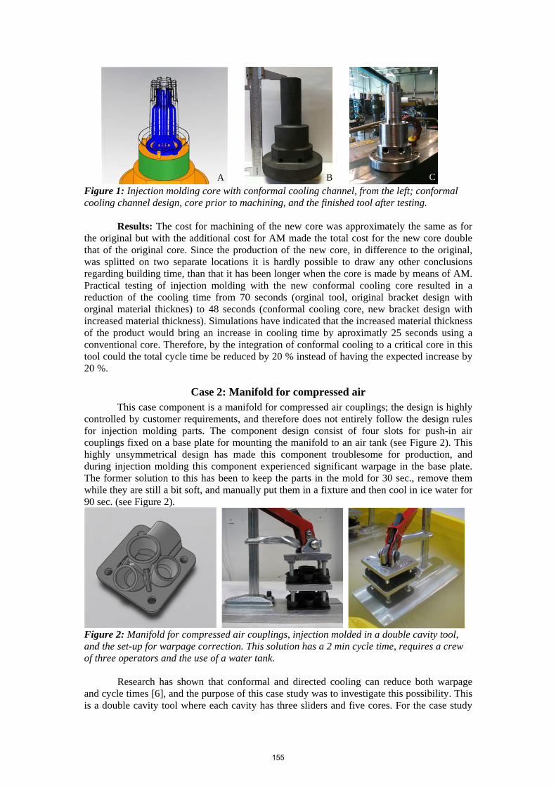
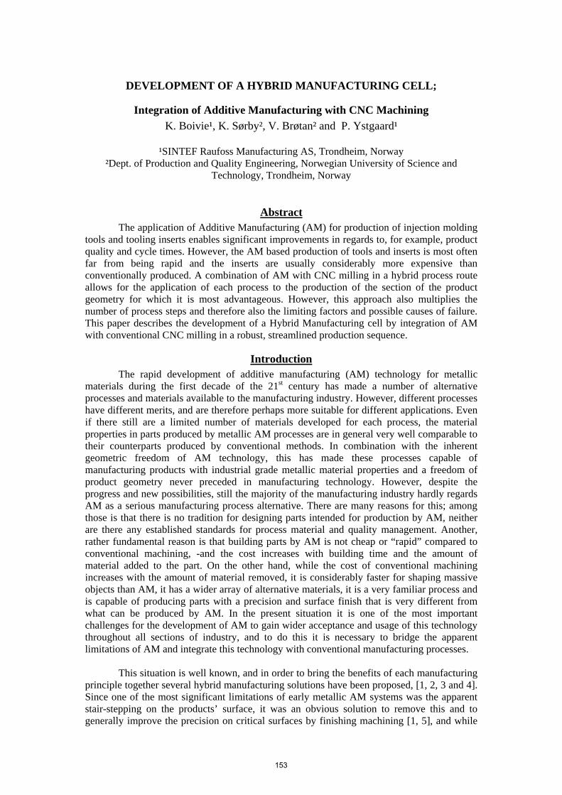
Figure 1: Injection molding core with conformal cooling channel, from the left; conformal cooling channel design, core prior to machining, and the finished tool after testing.
Results: The cost for machining of the new core was approximately the same as for the original but with the additional cost for AM made the total cost for the new core double that of the original core. Since the production of the new core, in difference to the original, was splitted on two separate locations it is hardly possible to draw any other conclusions regarding building time, than that it has been longer when the core is made by means of AM. Practical testing of injection molding with the new conformal cooling core resulted in a reduction of the cooling time from 70 seconds (orginal tool, original bracket design with orginal material thicknes) to 48 seconds (conformal cooling core, new bracket design with increased material thickness). Simulations have indicated that the increased material thickness of the product would bring an increase in cooling time by aproximatly 25 seconds using a conventional core. Therefore, by the integration of conformal cooling to a critical core in this tool could the total cycle time be reduced by 20 % instead of having the expected increase by 20 %.
Case 2: Manifold for compressed air This case component is a manifold for compressed air couplings; the design is highly controlled by customer requirements, and therefore does not entirely follow the design rules for injection molding parts. The component design consist of four slots for push-in air couplings fixed on a base plate for mounting the manifold to an air tank (see Figure 2). This highly unsymmetrical design has made this component troublesome for production, and during injection molding this component experienced significant warpage in the base plate. The former solution to this has been to keep the parts in the mold for 30 sec., remove them while they are still a bit soft, and manually put them in a fixture and then cool in ice water for 90 sec. (see Figure 2).
Figure 2: Manifold for compressed air couplings, injection molded in a double cavity tool, and the set-up for warpage correction. This solution has a 2 min cycle time, requires a crew of three operators and the use of a water tank. Research has shown that conformal and directed cooling can reduce both warpage and cycle times [6], and the purpose of this case study was to investigate this possibility. This is a double cavity tool where each cavity has three sliders and five cores. For the case study
A B C
155
was a new set consisting of one cavity with sliders and cores manufactured. Similar to case 1, this new tool was built in a hybrid manufacturing procedure; the base parts was milled from Orvar Supreme tool steel [7] at a local tool maker company, sent to ConceptLaser for AM of the remaining part with the conformal cooling, and then returned to the local tool maker for machining, grinding and polishing to required precision and surface quality. Results: During test runs the new tool showed a significant improvement in cooling; but the problem with warpage remained. However, if the part was kept in the tool until it had cooled down enough for the plastic to reach a rigid state, the parts came out with satisfactory flat base plate. This has made it possible to omit the fixture and water bath, and cut down the crew to one operator, but it has come at the price of an extension in cycle time to 5 minutes. Clearly, despite the advantage brought by integration of conformal cooling this cannot totally compensate for challenges that are built into the design of the product.
With hybrid manufacturing the number of process steps and the complexity of the information flow increased. This resulted in a disproportionate relationship between processing lead time and actual production time. However, there were some very practical issues of this approach to hybrid production of tooling inserts observed. For example: with more process steps and involving more different machines multiples the number of set-ups for each part. This in turn enhances the need safety margins and offsets added to the part geometry, which in turn will increase the material that has to be removed in the finishing machining. Conventional milling and AM building are two fundamentally different processes with fundamentally different process requirements that has to be fulfilled before the work piece can enter the subsequent process step. Even if the production of this mold had been carried out at the same location the set-up time and labor cost required at each process step would have been substantial, and if hybrid manufacturing shall be a more competitive part of an industrial production system there is need for a more integrated process solution.
The concept of the hybrid manufacturing cell
Principle and hardware The basic principle of the hybrid cell is to have an integrated cooperation between an
AM machine, in this particular case a ConceptLaser M2 Cusing machine (M2), and a CNC milling machine, in this particular case a Deckel-Maho 5-axis milling machine (DM), where each technology is used to produce the parts of the final tooling inserts which it is most advantageous to do so. For a typical injection molding insert this would mean that a base part will be milled from a block of raw material that has good milling properties and is compatible with the AM building conditions. Special attention in the primary milling operation would have to be given to having parallel surfaces on top and bottom and on the surface quality of the upper surface that will serve as a substrate during the AM building. The base part will then be moved to the M2 machine where the section of the insert with the more complex geometry, typically the conformal cooling, is added to the base part. Finally, after completed AM building, the raw product will be returned to the DM machine for finishing machining to desired dimensions and surface roughness.
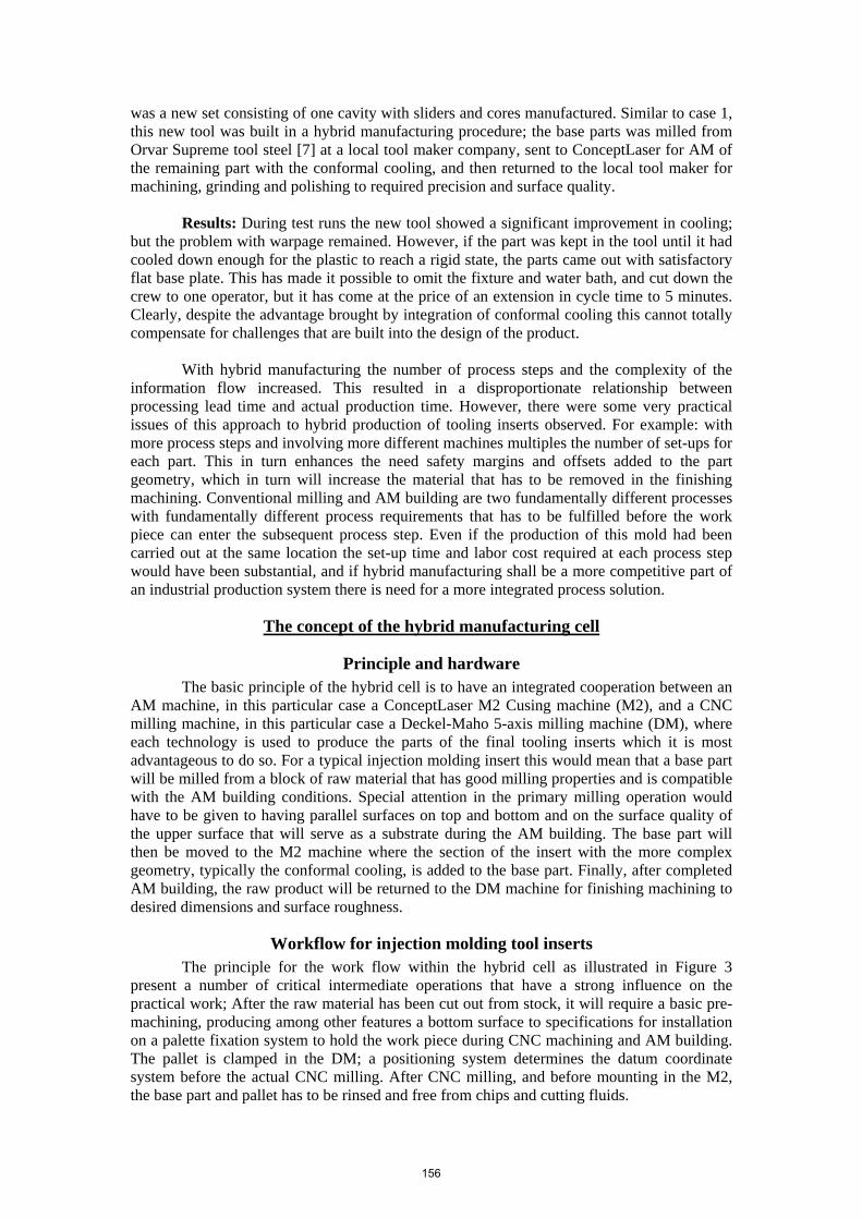
Workflow for injection molding tool inserts The principle for the work flow within the hybrid cell as illustrated in Figure 3
present a number of critical intermediate operations that have a strong influence on the practical work; After the raw material has been cut out from stock, it will require a basic pre-machining, producing among other features a bottom surface to specifications for installation on a palette fixation system to hold the work piece during CNC machining and AM building. The pallet is clamped in the DM; a positioning system determines the datum coordinate system before the actual CNC milling. After CNC milling, and before mounting in the M2, the base part and pallet has to be rinsed and free from chips and cutting fluids.
156
Figure 3: Typical workflow for production of injection molding inserts in the hybrid manufacturing cell. Preparatory operations for AM building marked with * would be desirable to keep at a minimum or, if possible, to be avoided altogether.
The quality and actual dimensions of the part need to be controlled, and dependent on
the material there may be a hardening operation required. The issues of powder handling; filling and leveling the powder prior to the AM building, and rinsing from powder after completed could be a topic for further development of the hybrid cell, but will not be addressed at this stage. After removal from the M2, the “raw” insert will require a heat treatment to remove tensions and acquire the desired hardness, before it is returned to the DM for finishing machining. As has been pointed out in Figure 3, there are a number of the intermediate operations that would be desirable to keep at a minimum or, if possible, entirely avoid.
Base part material A good rule of thumb is to keep the number of operations as small as possible, and
therefore is it the ambition of the development of the hybrid cell to find a working model that keeps the number of operations to a bare minimum while maintaining a practical working order and product quality. For the practical development of the hybrid cell, this emphasizes the need for an efficient, workable clamping and positioning system, and also raises some critical issues regarding the choice of material and process conditions for the base part.
Three different steels have been evaluated as potential base part materials; Orvar Supreme [7] is a traditional tool steel, corresponding to the standards Premium AISI H13 and DIN W.nr. 1.2344 that is very commonly used for injection molding tools on the Nordic market. This steel has also been used successfully for hybrid manufacturing of injection molding inserts described in case 2. Since the steel material used in the AM building corresponds to DIN W.nr. 1.2709 [8], a sample of the same steel has also been included in the evaluation. This is, in difference to Orvar, a maraging steel that is tempered to desired hardness by age hardening at a considerably lower temperature than conventional tool steels: 490°C in comparison to 1020°C – 1030°C for Orvar. This would in practice mean that an intermediate hardening operation between CNC machining and AM building could be eliminated from the process. The third material for this investigation was Marlok C1650 [9], a tool steel that shares the age hardening properties with the AM tool steel and W.nr.1.2709, but is most commonly used for demanding tooling applications such as aluminum die casting tools.
157
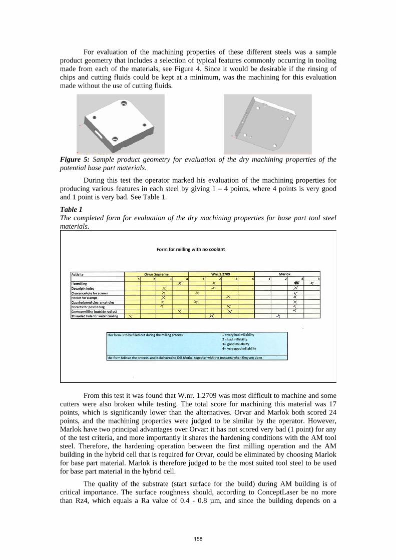
For evaluation of the machining properties of these different steels was a sample product geometry that includes a selection of typical features commonly occurring in tooling made from each of the materials, see Figure 4. Since it would be desirable if the rinsing of chips and cutting fluids could be kept at a minimum, was the machining for this evaluation made without the use of cutting fluids.
Figure 5: Sample product geometry for evaluation of the dry machining properties of the potential base part materials.
During this test the operator marked his evaluation of the machining properties for producing various features in each steel by giving 1 – 4 points, where 4 points is very good and 1 point is very bad. See Table 1.
Table 1 The completed form for evaluation of the dry machining properties for base part tool steel materials.
From this test it was found that W.nr. 1.2709 was most difficult to machine and some cutters were also broken while testing. The total score for machining this material was 17 points, which is significantly lower than the alternatives. Orvar and Marlok both scored 24 points, and the machining properties were judged to be similar by the operator. However, Marlok have two principal advantages over Orvar: it has not scored very bad (1 point) for any of the test criteria, and more importantly it shares the hardening conditions with the AM tool steel. Therefore, the hardening operation between the first milling operation and the AM building in the hybrid cell that is required for Orvar, could be eliminated by choosing Marlok for base part material. Marlok is therefore judged to be the most suited tool steel to be used for base part material in the hybrid cell.
The quality of the substrate (start surface for the build) during AM building is of critical importance. The surface roughness should, according to ConceptLaser be no more than Rz4, which equals a Ra value of 0.4 - 0.8 µm, and since the building depends on a
158

energy transfer by a laser, it is also important that the laser is not reflected from the substrate’s surface. A second sample block was produced to investigate the possibility to mill a surface that could fulfill these requirements, see Figure 5. Ten different grooves were milled with different cutters, feed and spindle speed. No cutting fluid was used for this test either.
Figure 5: Sample block for investigation of milling surfaces.
Figure 6: Mahr Perthometer M2 and the milling surface testing sample block.
As can be seen in Figure 5 there was not a dramatic difference between the surfaces produced with the different milling parameters. Surface roughness measurements with a Mahr Perthometer M2, see Figure 6, gave a roughness span of Ra = 0.3 - 0.6 µm which fulfils the requirement. However, as also can be seen in Figure 5, all surfaces were rather reflective to light, which would not be optimal in respect to laser absorption. There are still some differences and the most promising groove was milled with a 10 mm end mill and a cutting speed of 50 m/min, a feed of 0,111 mm/tooth and a spindle speed of 1500 rpm. The outcome will change with different parameters and tools, therefore these figures should not be considered as absolute, and it is not impossible that a less reflective surface could be achieved with further experiments. Otherwise, the alternatives are to either glass/sandblast the surface or to apply a fine coating that will reduce the reflection and evaporate when heated by the laser; one possibility could be to paint the substrate with a black color marker.
Clamping and fixation: Positioning and precision The M2 machine is designed with two separate stations; one for the manual powder
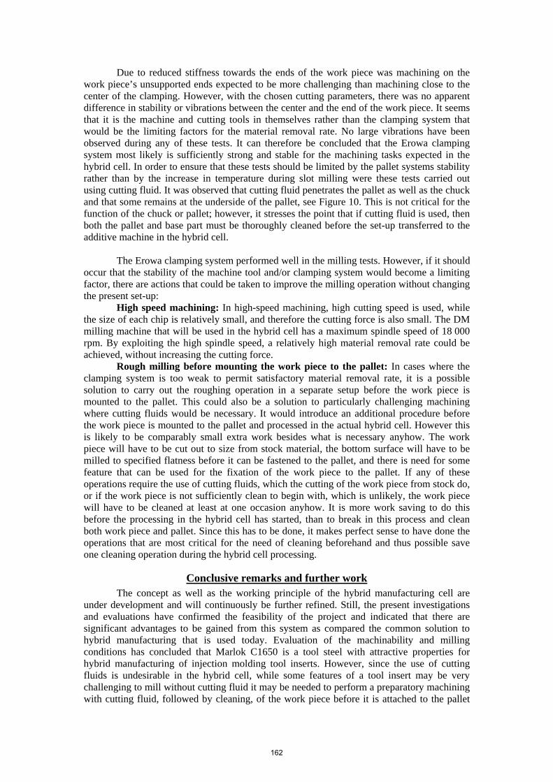
handling and preparation for setting up a build, such as installation of the substrate (base plate or base part), and one process station for the actual building process. The build- and material, containers are set in a carrier system that transports these between the powder handling area and process station. Since the positioning of the carriage in the process station must be accurate in order for the laser zero point to remain the same as the set-up zero point in the build chamber and to maintain consistency from one build to the other, it is important to determine the deviations that could be expected due the movements of the carrier. For this purpose was the deviation of the build plate’s position measured during a series of repeated carrier movements. The tests were set up with a solid block of metal fastened to the build plate, and a digital indicator gauge with micron accuracy located in the process station took measurements of the position of the metal block. This test series involved 33 measurements in each axis, where the carrier was moved all the way to the handling station before returning to the process station for a new measurement. A second test series with measurements in the X- and Y- directions was also performed. For these measurements was only the base plate moved 140 mm up and down. These tests produced smaller deviations than the tests involving the full carrier movement. This seems reasonable, and indicates that what was being measured in the full movement tests was the total accuracy of the carrier positioning. The Z-axis zero-position of the build plate movement was reconfigured in the handling station before every new measurement was taken, see Figure 7. The results of these tests show that on most occasions did the carrier positioning exceeded the gauge accuracy. Based on these results it is a reasonable conclusion that the positioning of the carrier has an insignificant effect on the overall machine accuracy.
159
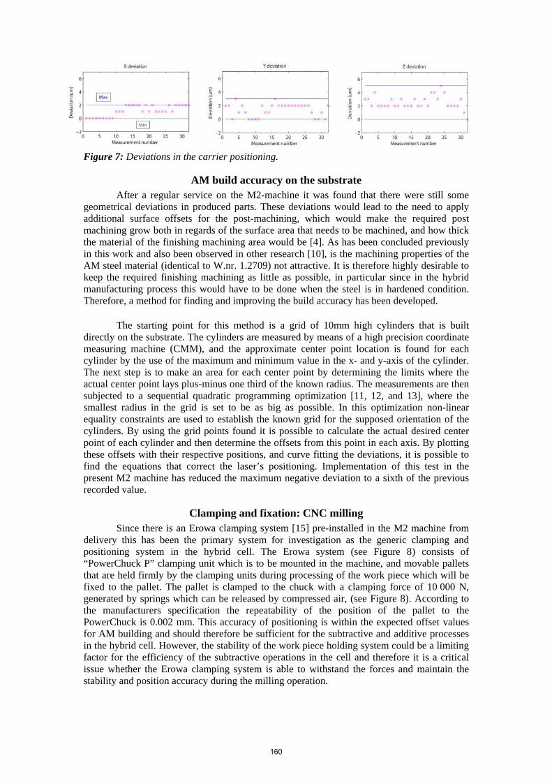
Figure 7: Deviations in the carrier positioning.
AM build accuracy on the substrate After a regular service on the M2-machine it was found that there were still some
geometrical deviations in produced parts. These deviations would lead to the need to apply additional surface offsets for the post-machining, which would make the required post machining grow both in regards of the surface area that needs to be machined, and how thick the material of the finishing machining area would be [4]. As has been concluded previously in this work and also been observed in other research [10], is the machining properties of the AM steel material (identical to W.nr. 1.2709) not attractive. It is therefore highly desirable to keep the required finishing machining as little as possible, in particular since in the hybrid manufacturing process this would have to be done when the steel is in hardened condition. Therefore, a method for finding and improving the build accuracy has been developed.
The starting point for this method is a grid of 10mm high cylinders that is built directly on the substrate. The cylinders are measured by means of a high precision coordinate measuring machine (CMM), and the approximate center point location is found for each cylinder by the use of the maximum and minimum value in the x- and y-axis of the cylinder. The next step is to make an area for each center point by determining the limits where the actual center point lays plus-minus one third of the known radius. The measurements are then subjected to a sequential quadratic programming optimization [11, 12, and 13], where the smallest radius in the grid is set to be as big as possible. In this optimization non-linear equality constraints are used to establish the known grid for the supposed orientation of the cylinders. By using the grid points found it is possible to calculate the actual desired center point of each cylinder and then determine the offsets from this point in each axis. By plotting these offsets with their respective positions, and curve fitting the deviations, it is possible to find the equations that correct the laser’s positioning. Implementation of this test in the present M2 machine has reduced the maximum negative deviation to a sixth of the previous recorded value.
Clamping and fixation: CNC milling Since there is an Erowa clamping system [15] pre-installed in the M2 machine from
delivery this has been the primary system for investigation as the generic clamping and positioning system in the hybrid cell. The Erowa system (see Figure 8) consists of “PowerChuck P” clamping unit which is to be mounted in the machine, and movable pallets that are held firmly by the clamping units during processing of the work piece which will be fixed to the pallet. The pallet is clamped to the chuck with a clamping force of 10 000 N, generated by springs which can be released by compressed air, (see Figure 8). According to the manufacturers specification the repeatability of the position of the pallet to the PowerChuck is 0.002 mm. This accuracy of positioning is within the expected offset values for AM building and should therefore be sufficient for the subtractive and additive processes in the hybrid cell. However, the stability of the work piece holding system could be a limiting factor for the efficiency of the subtractive operations in the cell and therefore it is a critical issue whether the Erowa clamping system is able to withstand the forces and maintain the stability and position accuracy during the milling operation.
160

Figure 8: Erowa PowerChuck P [15] 158 x 230, for mounting onto the work table in the milling machine, and a movable pallet, Ø148 for work piece fixation. The PowerChuck release function is operated by compressed air. Automatic air supply can be made available in the DM machine.
A series of milling tests has been performed in order to investigate the stability of the clamping system. For these tests has the work piece material been a mild steel with a hardness of 260 HB, (approximately the same as HRc 27), which is comparable to unhardened tool steel; -Marlok is delivered in soft annealed condition at HRc 28 – 32. The milling tool was a Ø20 end mill (ISCAR HM90 E90A-D20-3-C20) with indexable carbide inserts. The tests were carried out as side milling and slot milling in a Bridgeport VMC milling machine. The properties of this machine (stiffness, spindle design, etc.) are comparable to the properties of the DM machine that will be used in the hybrid cell and the working space of the DM is too small to carry out the necessary measurements, see Figure 9.
Figure 9: The Erowa PowerChuck and pallet set up for machining test in the Bridgeport VMC
Figure 10: Cutting fluid penetrates the pallet and chuck.
The cutting data used in the tests are shown in Table 2. The material removal rate under these conditions is satisfactory for a rough machining operation on work pieces of the size that will be processed in the hybrid cell.
Table 2 Test data for the milling tests Side milling Slot milling Depth-of-cut, ap 5.0 mm 3.0 mm Engagement, ae 4.0 mm 20.0 mm Spindle speed, N 6000 r/min 3000 r/min Cutting speed, vc 380 m/min 190 m/min Feed speed, vf 1800 mm/min 900 mm/min Feed per tooth, fz 0.1 mm 0.1 mm Material removal rate, MRR 36 cm3/min 54 cm3/min
161
Due to reduced stiffness towards the ends of the work piece was machining on the work piece’s unsupported ends expected to be more challenging than machining close to the center of the clamping. However, with the chosen cutting parameters, there was no apparent difference in stability or vibrations between the center and the end of the work piece. It seems that it is the machine and cutting tools in themselves rather than the clamping system that would be the limiting factors for the material removal rate. No large vibrations have been observed during any of these tests. It can therefore be concluded that the Erowa clamping system most likely is sufficiently strong and stable for the machining tasks expected in the hybrid cell. In order to ensure that these tests should be limited by the pallet systems stability rather than by the increase in temperature during slot milling were these tests carried out using cutting fluid. It was observed that cutting fluid penetrates the pallet as well as the chuck and that some remains at the underside of the pallet, see Figure 10. This is not critical for the function of the chuck or pallet; however, it stresses the point that if cutting fluid is used, then both the pallet and base part must be thoroughly cleaned before the set-up transferred to the additive machine in the hybrid cell.
The Erowa clamping system performed well in the milling tests. However, if it should
occur that the stability of the machine tool and/or clamping system would become a limiting factor, there are actions that could be taken to improve the milling operation without changing the present set-up:
High speed machining: In high-speed machining, high cutting speed is used, while the size of each chip is relatively small, and therefore the cutting force is also small. The DM milling machine that will be used in the hybrid cell has a maximum spindle speed of 18 000 rpm. By exploiting the high spindle speed, a relatively high material removal rate could be achieved, without increasing the cutting force.
Rough milling before mounting the work piece to the pallet: In cases where the clamping system is too weak to permit satisfactory material removal rate, it is a possible solution to carry out the roughing operation in a separate setup before the work piece is mounted to the pallet. This could also be a solution to particularly challenging machining where cutting fluids would be necessary. It would introduce an additional procedure before the work piece is mounted to the pallet and processed in the actual hybrid cell. However this is likely to be comparably small extra work besides what is necessary anyhow. The work piece will have to be cut out to size from stock material, the bottom surface will have to be milled to specified flatness before it can be fastened to the pallet, and there is need for some feature that can be used for the fixation of the work piece to the pallet. If any of these operations require the use of cutting fluids, which the cutting of the work piece from stock do, or if the work piece is not sufficiently clean to begin with, which is unlikely, the work piece will have to be cleaned at least at one occasion anyhow. It is more work saving to do this before the processing in the hybrid cell has started, than to break in this process and clean both work piece and pallet. Since this has to be done, it makes perfect sense to have done the operations that are most critical for the need of cleaning beforehand and thus possible save one cleaning operation during the hybrid cell processing.
Conclusive remarks and further work The concept as well as the working principle of the hybrid manufacturing cell are
under development and will continuously be further refined. Still, the present investigations and evaluations have confirmed the feasibility of the project and indicated that there are significant advantages to be gained from this system as compared the common solution to hybrid manufacturing that is used today. Evaluation of the machinability and milling conditions has concluded that Marlok C1650 is a tool steel with attractive properties for hybrid manufacturing of injection molding tool inserts. However, since the use of cutting fluids is undesirable in the hybrid cell, while some features of a tool insert may be very challenging to mill without cutting fluid it may be needed to perform a preparatory machining with cutting fluid, followed by cleaning, of the work piece before it is attached to the pallet
162

and processing in the actual hybrid cell can start. Flat milling of the tool steel that would be used as base part material in the hybrid cell can be set to fulfill the requirements for surface roughness; however it is likely to produce a surface that may require some extra treatment to ensure satisfactory laser absorption. The precision of the Erowa pallet system and the movements in the ConceptLaser M2 Cusing machine are not limiting factors for the precision of the hybrid cell. An improved system for determining and compensation of the laser deviation has been developed, which has resulted in greatly improved precision in the ConeptLaser M2 Cusing machine that will be used in the hybrid cell. The Erowa PowerChuck and pallet system is rigid and strong enough to withstand the loads expected during the milling operation. However, should a situation occur when the stability of this system would be unsatisfactory, there are actions that could be made to compensate for this with the present system and setup. An Erowa PowerChuck and palette system has been installed in the Deckel-Maho 5 axis milling machine, which together with the measuring probe and the preinstalled Erowa chuck in the ConceptLaser M2 Cusing machine, provides basic physical conditions for integrated operation of the hybrid cell.
Acknowledgements The development of the hybrid manufacturing cell is being supported by a collaboration of several national and international research projects and research programs; 7th FP EU project IC2 ,”Intelligent and Customized Tooling”(NMP-2009-4.0-5, Grant agreement no: 246172), NFR (Research Council of Norway) project HYPRO, and CRI Norman (Center for Research driven Innovation), have all contributed to the progress so far.
References [1] K.P. Karunakaran, S. Suryakumar, Vishal Pushpa, Sreenathbabu Akula, “Low cost integration of additive and subtractive processes for hybrid layered manufacturing”, Robotics and Computer-Integrated Manufacturing, Volume 26, Issue 5, October 2010, Pages 490-499, ISSN 0736-5845, DOI: 10.1016/j.rcim.2010.03.008. [2] Olivier Kerbrat, Pascal Mognol, Jean-Yves Hascoet, “A new DFM approach to combine machining and additive manufacturing”, Computers in Industry, In Press, Corrected Proof, Available online 6 May 2011, ISSN 0166-3615, DOI: 10.1016/j.compind.2011.04.003. [3] http://www.lasercusing.nl/content.php/en/270 [4] Hu, Z. (2002). "Determination of optimal build orientation for hybrid rapid-prototyping." Journal of Materials Processing Technology 130-131: 378-383. [5] S.O. Onuh, K.K.B. Hon, “Optimizing build parameters for improved surface finish in stereolithography”, International Journal of Machine Tools and Manufacture, Volume 38, Issue 4, March 1998, Pages 329-342, ISSN 0890-6955, DOI: 10.1016/S0890-6955(97)00068-0. [6] Rännar, L.E., “On Optimization of Injection Molding Cooling”, Doctoral thesis Norwegian University of Science and Technology, NTNU 2008:113, ISBN 978-82-471-8270 [7] http://www.uddeholm.com/files/PB_orvar_supreme_english.pdf [8]http://www.doerrenberg.de/fileadmin/template/doerrenberg/stahl/DatenblaetterDeu/1.2709_de.pdf [9] http://www.metso.com/MEP/info.nsf/WebWID/WTB-051025-22570-3FF66/$File/Marlok%20brochure%202005.pdf [10] Kempen, K., E. Yasa, et al. (2011). "Microstructure and mechanical properties of Selective Laser Melted 18Ni-300 steel." Physics Procedia 12: 255-263. [11] Fletcher, R. and M. J. D. Powell (1963). "A rapidly convergent descent method for minimization." The Computer Journal 6: 163. [12] Gill, P. E., W. Murray, et al. (1982). Practical Optimization, Academic Press. [13] Gill, P. E. and E. Wong (2010). SEQUENTIAL QUADRATIC PROGRAMMING METHODS . Energy. 0112: 1-75. [14] http://www.erowa.com/en/products-solutions/workholding-systems/prodnav/PPM-Standardization/power-chuck-p.html
163