development of a main landing gear attachment fitting ... · for these reasons hexcel rtm6 and...
TRANSCRIPT
UNCLASSIFIED
Executive summary
UNCLASSIFIED
Nationaal Lucht- en Ruimtevaartlaboratorium
National Aerospace Laboratory NLR
This report is based on a presentation held at the 31st SEICO 10 SAMPE EUROPE Conference, Paris, April 12 - 14, 2010.
Report no. NLR-TP-2009-732 Author(s) H.P.J. de Vries Report classification UNCLASSIFIED Date December 2010 Knowledge area(s) Lucht- en ruimtevaart constructie- en fabricagetechnologie Descriptor(s) ALCAS RTM Priform Landing gear Gear Rib
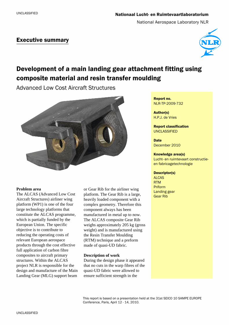
Development of a main landing gear attachment fitting using composite material and resin transfer moulding Advanced Low Cost Aircraft Structures
Problem area The ALCAS (Advanced Low Cost Aircraft Structures) airliner wing platform (WP1) is one of the four large technology platforms that constitute the ALCAS programme, which is partially funded by the European Union. The specific objective is to contribute to reducing the operating costs of relevant European aerospace products through the cost effective full application of carbon fibre composites to aircraft primary structures. Within the ALCAS project NLR is responsible for the design and manufacture of the Main Landing Gear (MLG) support beam
or Gear Rib for the airliner wing platform. The Gear Rib is a large, heavily loaded component with a complex geometry. Therefore this component always has been manufactured in metal up to now. The ALCAS composite Gear Rib weighs approximately 205 kg (gross weight) and is manufactured using the Resin Transfer Moulding (RTM) technique and a preform made of quasi-UD fabric. Description of work During the design phase it appeared that no cuts in the warp fibres of the quasi-UD fabric were allowed to ensure sufficient strength in the

UNCLASSIFIED
UNCLASSIFIED
Development of a main landing gear attachment fitting using composite material and resin transfer moulding Advanced Low Cost Aircraft Structures
Nationaal Lucht- en Ruimtevaartlaboratorium, National Aerospace Laboratory NLR Anthony Fokkerweg 2, 1059 CM Amsterdam, P.O. Box 90502, 1006 BM Amsterdam, The Netherlands Telephone +31 20 511 31 13, Fax +31 20 511 32 10, Web site: www.nlr.nl
corners of the gear rib. However, the geometry of the Gear Rib consists of 5 connected surfaces that normally cannot be covered with one fabric ply without cuts in the corners or wrinkles at the surfaces. In order to meet the no-cut criterion for warp fibres a novel laminating method was developed. In order to maintain the net-shaped thickness for each ply and prevent wrinkling at the corners a hot compaction cycle was carried out each 6 plies. The Gear Rib was injected in a one-shot injection process using a resin vessel with a capacity of 75 litre. Exothermal heat development inside the vessel was prevented through application of internal cooling. Exothermal heat development during cure was prevented by using oil heating/cooling for both internal and external tooling and the application of an additional dwell at 150 °C. Results and conclusions The ALCAS WP1 composite Gear Rib has been developed successfully using a one-shot RTM process with Cytec Cycom 977-20/Priform materials. During preforming a novel laminating method has been applied to prevent cuts in the warp fibres of the quasi UD fabric. The laminating method provided the required
mechanical properties in the corners of the component, but is too labour intensive to make the part affordable. However, recent developments in the field of dry fibre placement show that the sub-preforms on the inner tooling blocks can be made with dry fibre placement technology in the near future. Application of such automated manufacturing technologies will be required to improve the affordability of large, complex parts such as the composite Gear Rib. Due to the thick preforms and the hand lay-up manufacturing method many hot compaction cycles were required, resulting in staged binder powder in the first plies that were laminated. The staged binder powder blocked the infusion of these plies. These areas have been repaired afterwards with Cycom 823 RTM resin using an vacuum infusion process. Applicability The knowledge gained through the ALCAS project can be used for the design and manufacture of thick composite structures in general. This encompasses any heavily loaded primary structure, such as landing gear components, attachment fittings and brackets.

Nationaal Lucht- en Ruimtevaartlaboratorium National Aerospace Laboratory NLR
NLR-TP-2009-732
Development of a main landing gear attachment fitting using composite material and resin transfer moulding Advanced Low Cost Aircraft Structures
H.P.J. de Vries
This report is based on a presentation held at the 31st SEICO 10 SAMPE EUROPE Conference, Paris,
April 12 - 14, 2010.
The contents of this report may be cited on condition that full credit is given to NLR and the author.
This publication has been refereed by the Advisory Committee AEROSPACE VEHICLES.
Customer National Aerospace Laboratory NLR
Contract number ----
Owner National Aerospace Laboratory NLR
Division NLR Aerospace Vehicles
Distribution Unlimited
Classification of title Unclassified
December 2010 Approved by:
Author
Reviewer Managing department

NLR-TP-2009-732
2
Contents
Summary 3
1. Introduction 4
1.1 Project background 4
1.2 Objectives 4
1.3 Gear Beam geometry and nomenclature 4
2. Material and process selection 6
2.1 Selection of manufacturing method and material 6
2.2 Modification of cure cycle 7
3. Structural design 7
3.1 Numerical approach 7
3.2 Analyses results 8
4. Manufacturing 10
4.1 Tooling 10
4.2 Preforming 11
4.3 Injection and results 13
5. Conclusions 15
Acknowledgement 16
References 16

NLR-TP-2009-732
3
DEVELOPMENT OF THE ALCAS MAIN LANDING GEAR ATTACHMENT FITTING
Ing. HENRI DE VRIES
National Aerospace Laboratory NLR
P.O. Box 90502, 1006 BM Amsterdam, Netherlands
SUMMARY
Within platform 1 of the EU funded project ALCAS (ref. 1) a composite main landing
gear attachment fitting (Gear Rib) has been developed. The main part of the complex
shaped, heavily loaded primary structure consists of laminates of 60 -70 mm thick.
The one-piece structure weighed 205 kg (gross weight) and has been made using a
single-shot Resin Transfer Moulding (RTM) process.
During the material and process development phase NLR selected a quasi UD-
weave fabric with Cytec Cycom 977-20/Priform because of its low exothermal heat
development and good toughness characteristics. During the design phase the finite
element analysis revealed that due to the high loads only cuts in the warp direction of
the fabric (along the UD fibres) were allowed. In order to comply with this
requirement NLR developed a novel laminating method for quasi-UD fabrics. The
Gear Rib preform was manufactured manually on oil heated tooling blocks which
were also used for handling the preform weighing 140 kg. The preform was infused
successfully with 977/20 resin in a single shot RTM process using matched metal
moulds.
This paper will highlight the achievements and lessons learnt during the development
of the composite Gear Rib. The novel laminating method used and possibilities to
automate the preform manufacturing for these type of structures will be discussed.
Furthermore RTM processing of large, complex structures will be discussed.

NLR-TP-2009-732
4
1. INTRODUCTION
1.1 Project background
The ALCAS (Advanced Low Cost Aircraft Structures) Airliner Wing platform (WP1) is
one of the four large technology platforms that constitute the ALCAS programme,
which is partially funded by the European Union. The ALCAS program itself is a large
consortium of 59 airframe manufacturers, component suppliers, research institutes
and universities. The specific objective is to contribute to reducing the operating
costs of relevant European aerospace products through the cost effective full
application of carbon fibre composites to aircraft primary structures. The specific
objective of the Airliner Wing platform is a 20% weight saving in the wing structure
with zero increase in recurring cost against the state of the art metallic wing (taken
from A330).
Figure 1 gives an overview of the lateral wing that is developed within ALCAS WP1.
The National Aerospace Laboratory NLR is responsible for the development of the
Gear Rib, which is located behind the rear spar, in between the upper skin and lower
skin (encircled).
Figure 1 Overview of the ALCAS WP1 lateral wing (Source: Airbus Operations Ltd)
1.2 Objectives
The program objectives regarding the composite main landing gear attachment
fittings are:

NLR-TP-2009-732
5
To develop optimum design concepts using appropriate stress methodologies,
considering series production (no-shim philosophy), assembly, access and
certification requirements
To develop both advanced and low cost liquid resin process technologies
To manufacture the fittings and support assembly
Up to now, Airbus always applied a metal (aluminium) Gear Rib, because of its
complex shape and interfaces with the rear spar and upper and lower wing cover.
However, a composite Gear Rib probably can lead to weight reduction while
improving the fatigue properties. The development of a composite Gear Rib with a
net-shaped geometry at all interfaces and 20% weight savings at the same life cycle
costs is therefore the challenge of this project.
1.3 Gear Beam geometry and nomenclature
The initial geometry of the Gear Rib, as provided by Airbus Operations Ltd at the
start of the project, is given in figure 2. It comprises of a large forward lug (Lug A),
two smaller lugs (Forward and Aft lug B), the upper and lower flange for connection
with the wing covers and the rear spar flange. The estimated thickness of lugs B is
60 mm and the estimated thickness of lug A is even 72 mm.
Figure 2 Initial design of the Gear Rib and its nomenclature
Lower flange
Upper flange
Forward lug B Lug A Rear spar flange
Aft lug B
Shear web
NLR-TP-2009-732
6
2. MATERIAL AND PROCESS SELECTION
2.1 Selection of manufacturing method and material
Because of the no-shim philosophy and the interfaces with the upper and lower
cover, the rear spar and the landing gear, the dimensions of the Gear Rib have to be
very accurate. Besides, the initial design of the Gear Rib with three integrated lugs
and reinforcement ribs running from the shear web to forward lug B is very complex
and challenging. The material and manufacturing method will have to allow for 3D-
laminating of plies. Furthermore exothermal heat development can be expected in
the rather thick lug areas.
Resin Transfer Moulding (RTM) using matched moulds is the most commonly used
method to manufacture composite parts with accurate dimensions. The drapeability
of dry fabrics usually is better than those of impregnated materials. Furthermore it
can be expected that dry fabric preforms can be manufactured automatically in the
near future using 3D-weaving or dry fibre placement. Therefore RTM is selected as
manufacturing method
Aerospace RTM resins for structural applications are cured at 150 ºC or higher and
develop exothermal heat during cure. Because of the thickness of the structure a
RTM resin with low exothermal heat development is preferred. Furthermore low
polymerisation shrinkage and good toughness properties are required to prevent
shrinkage cracks. For these reasons Hexcel RTM6 and Cytec Cycom 890 are
considered less suitable. Screening tests on 90-mm thick CFRP elements using
Bakelite EPS601 and Cytec Cycom 977-20/ Priform resin revealed that both 180 ºC
curing resins are suitable for manufacturing structures up to 90-mm (ref. 2). However,
an intermediate dwell is preferred to prevent exothermal peak temperatures above
190 ºC (see section 2.2). Finally Cytec Cycom 977-20/Priform is selected because of
its better mechanical properties.
Regarding reinforcement material a semi-unidirectional fabric is preferred. Fabric is
required for its handling and drapeability properties and a semi-unidirectional weave
style is required from a structural point of view. Since no semi-UD fabrics with co-
woven Priform yarns were available, a specific twill weave fabric with 85/15 warp/weft
fibre distribution and an areal weight of 410 gsm (excl. Priform and binder) was
developed by Cytec. In order to enhance preforming and the ability to make preforms
with net-shaped thickness (Vf 57.5%) a coating of Cytec Cycom 7720 binder was
applied.
NLR-TP-2009-732
7
2.2 Modification of cure cycle
To prevent thermal degradation due to excessive exothermal heat development
additional research regarding the cure cycle has been carried out. For Cytec Cycom
977-20/Priform a low injection temperature of maximum 85 ºC is required to prevent
Priform dissolution during injection. After injection an intermediate dwell of 70
minutes at 125 ±5 ºC is recommended in order to dissolve Priform into the resin (ref.
3). When heating the resin to cure temperature after completion of the dissolution
dwell, the resin starts to gel at approximately 136 ºC. Tests at several temperatures
above the gel temperature have been carried out to find the optimum dwell
temperature. For laminates up to 90-mm, a second dwell at 150 ºC for 40 minutes
proved to be sufficient to prevent peak temperatures above 180 ºC. Mechanical
properties of coupons manufactured with an additional dwell at 150 ºC have been
determined for design purposes (ref. 4). These properties proved to be in line with
mechanical properties determined by Cytec (ref. 3).
3. STRUCTURAL DESIGN
3.1 Numerical approach
In the design process, two separate Finite Element Models are used. First, a local
model of the Gear Rib design is generated. The local model consists of the Gear Rib
and a limited part of the surrounding structure. This local model, consisting of 2D-
shell elements, is used to investigate design changes and to optimize design details
of the Gear Rib. Furthermore the dimensioning of the lugs in the area around the
holes is based on empirical analyses of bolted joints performed by Hart-Smith (ref. 5)
and extensive in-house experience with RTM produced lug specimens of large
thickness (ref. 6 and 7)
Next, the FE model is incorporated in a (global) integrated model by Airbus UK. The
integrated models contain the entire wing structure and the test structure for load
introduction, see figure 3. The integrated model is used to generate more accurate
stresses, strains and interface loads. The loads at the interface are introduced by
bolts, modelled by beam elements. Bolt loads are used to determine the criticality of
the bolts themselves and the criticality of the upper and lower flange of the Gear Rib
(bearing bypass).
NLR-TP-2009-732
8
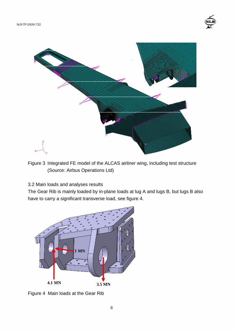
Figure 3 Integrated FE model of the ALCAS airliner wing, including test structure
(Source: Airbus Operations Ltd)
3.2 Main loads and analyses results
The Gear Rib is mainly loaded by in-plane loads at lug A and lugs B, but lugs B also
have to carry a significant transverse load, see figure 4.
Figure 4 Main loads at the Gear Rib
4.1 MN
1 MN
3.5 MN

NLR-TP-2009-732
9
Several design iterations were required to optimize the Gear Rib design. A soft lay-up
with a rather high degree of ±45º plies was required for the major part of the laminate
in order to obtain sufficient distribution of loads over the bolted areas. For the lugs a
quasi-isotropic lay-up gave the best results. Compared to the initial design, the
thickness of Lug A could be decreased from 72 to 70 mm while the thicknesses of
lugs B could be maintained at 60 mm. However, due to the high loads the thickness
of the upper and lower cover was increased to 60 mm and the shear web was
calculated at 40 mm. The rear spar flange could be maintained at 20 mm, resulting in
a total weight of 168 kg (including bushings). The final design is shown in figure 5.
Figure 5 Final geometry of the ALCAS WP1 Gear Rib
It is remarked that more accurate analysis results would have been obtained for
these thick laminates if composite brick element would have been used (e.g.
continuum shells in Abaqus). However, although they have the appearance of solid
elements, they compute as shells and have the same inaccuracy in their transverse
shear behaviour. For better transverse shear deformations and transverse shear
stresses multiple continuum shells need to be stacked for these thick laminates,
which becomes computationally very inefficient for the thickness considered here.
More efficient ways have been investigated and are available (ref. 8), but in any case
the FE model needs to be much more detailed than the shell modelling to obtain
more accurate results. This also complicates incorporation in the MLG integration
model.
NLR-TP-2009-732
10
4. MANUFACTURING
4.1 Tooling
The RTM tooling for the Gear Rib needs to provide the following functions:
Heating for preforming and curing
Hoisting of sub-preforms and assembled preform
Injection of the preform using multiple injection points
Accurate dimensions of the cured component
Compensation for polymerisation shrinkage (to prevent shrinkage cracks)
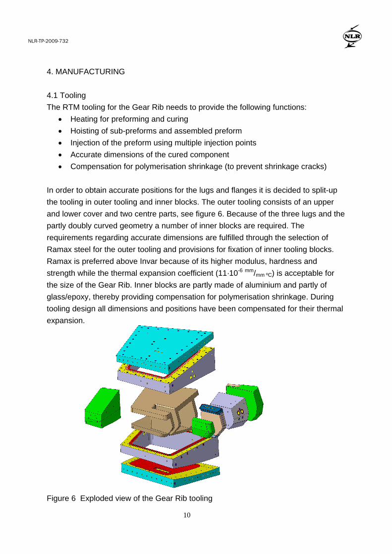
In order to obtain accurate positions for the lugs and flanges it is decided to split-up
the tooling in outer tooling and inner blocks. The outer tooling consists of an upper
and lower cover and two centre parts, see figure 6. Because of the three lugs and the
partly doubly curved geometry a number of inner blocks are required. The
requirements regarding accurate dimensions are fulfilled through the selection of
Ramax steel for the outer tooling and provisions for fixation of inner tooling blocks.
Ramax is preferred above Invar because of its higher modulus, hardness and
strength while the thermal expansion coefficient (11·10-6 mm/mm ºC) is acceptable for
the size of the Gear Rib. Inner blocks are partly made of aluminium and partly of
glass/epoxy, thereby providing compensation for polymerisation shrinkage. During
tooling design all dimensions and positions have been compensated for their thermal
expansion.
Figure 6 Exploded view of the Gear Rib tooling

NLR-TP-2009-732
11
Both outer tooling and inner blocks are heated using oil heating because of its
accuracy and the ability to apply cooling in case of exothermal heat development.
Furthermore oil heating provides the possibility to heat each inner tooling block
individually thereby enabling parallel manufacture of sub-preforms on each tooling
block.
The fixation holes in each inner tooling block are also used to hoist individual sub-
preforms on these tooling blocks. Furthermore the assembled preform can be
handled with a special hoisting device that secures the position of each individual
tooling block and thus the complete preform.
4.2 Preforming
During the design phase it appeared that no cuts in the warp fibres of the quasi-UD
fabric were allowed to ensure sufficient strength in the corners of the Gear Rib.
However, in the area between Lug A and Forward Lug B the geometry of the Gear
Rib consists of 5 connected surfaces that normally cannot be covered with one fabric
ply without cuts in the corners or wrinkles at the surfaces. In order to meet the no-cut
criterion for warp fibres a novel laminating method was applied. For cube-like
structures like the preform shown in figure 7 (angles between individual surfaces
close to 90º) each surface can be covered without cuts in warp fibres if [+45] and [-
45] plies are combined. If a [45] ply with only cuts in weft fibres is laminated on the
block according to step 1, 2, 3 of figure 7, some surfaces contain the intended +45º
fibre direction but some surfaces also contain a -45º fibre direction. Also some
surfaces are not covered. However, if a [-45] ply is laminated next to the [45] ply it
results in a sub-preform containing one 45º ply and one -45º ply at each surface.
Figure 7 Cut and folding method used to avoid cuts in warp fibres at corners
For a combination of a [0] ply and [90] ply the same result can be obtained but the
warp fibres are cut at the division line where the ends of the folded [0] plies meet

NLR-TP-2009-732
12
each other. However, this is not at a corner and can be distributed over the surface of
the plane. The result for 0/90 and +45/-45 plies is shown in figure 8.
Figure 8 Results of novel laminating method for cube-like structures
Roughly half of the total preform consists of sub-preforms that can be made on the
inner tooling blocks. In order to maintain the net-shaped thickness for each ply and
prevent wrinkling at the corners a hot compaction cycle was carried out each 6 plies.
After completion of the sub-preforms the blocks are assembled, see figure 9.
Figure 9 Assembly of sub-preforms.
NLR-TP-2009-732
13
Next the remaining plies are laminated on top of the assembled blocks to complete
the preform. Hereby also the novel laminating method is used to laminate the plies
inside lugs B after assembly of the sub-preforms.
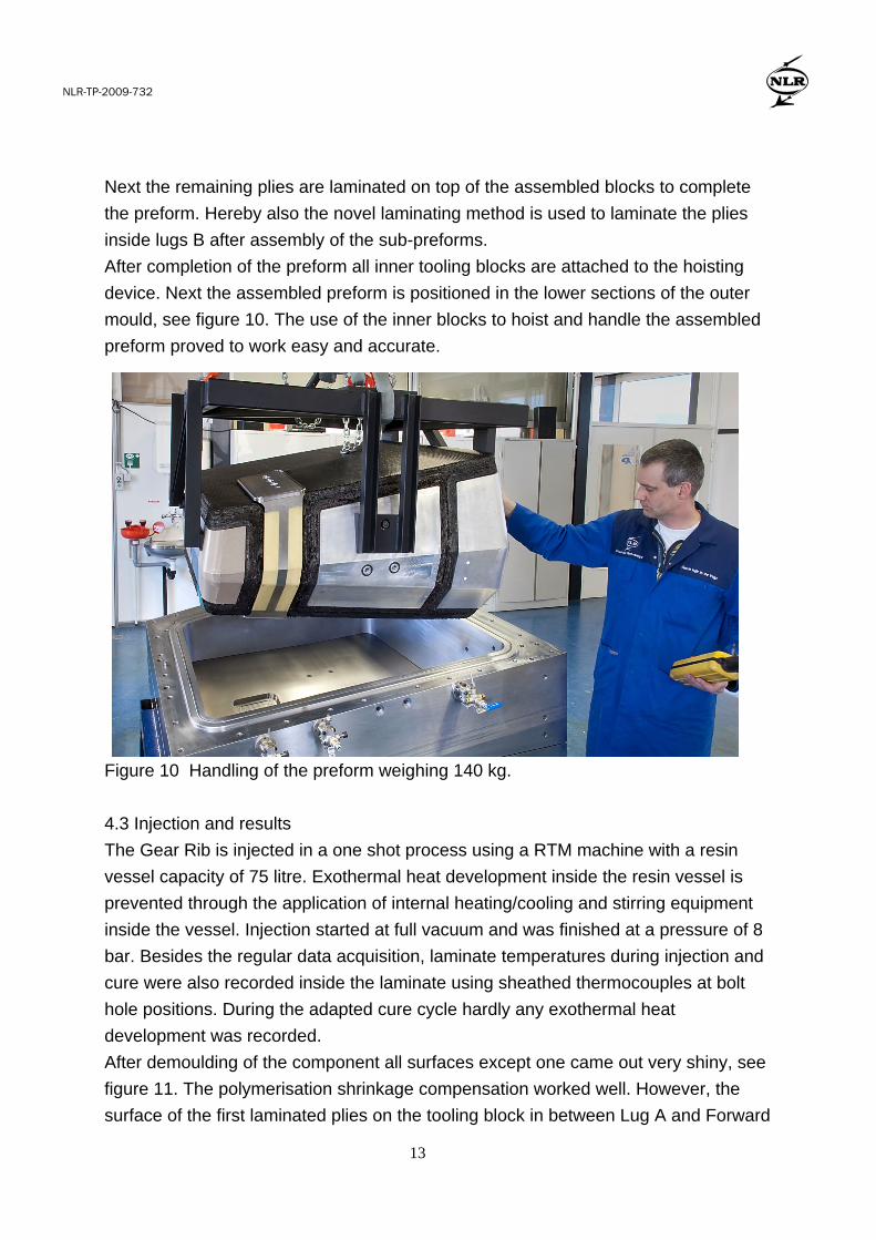
After completion of the preform all inner tooling blocks are attached to the hoisting
device. Next the assembled preform is positioned in the lower sections of the outer
mould, see figure 10. The use of the inner blocks to hoist and handle the assembled
preform proved to work easy and accurate.
Figure 10 Handling of the preform weighing 140 kg.
4.3 Injection and results
The Gear Rib is injected in a one shot process using a RTM machine with a resin
vessel capacity of 75 litre. Exothermal heat development inside the resin vessel is
prevented through the application of internal heating/cooling and stirring equipment
inside the vessel. Injection started at full vacuum and was finished at a pressure of 8
bar. Besides the regular data acquisition, laminate temperatures during injection and
cure were also recorded inside the laminate using sheathed thermocouples at bolt
hole positions. During the adapted cure cycle hardly any exothermal heat
development was recorded.
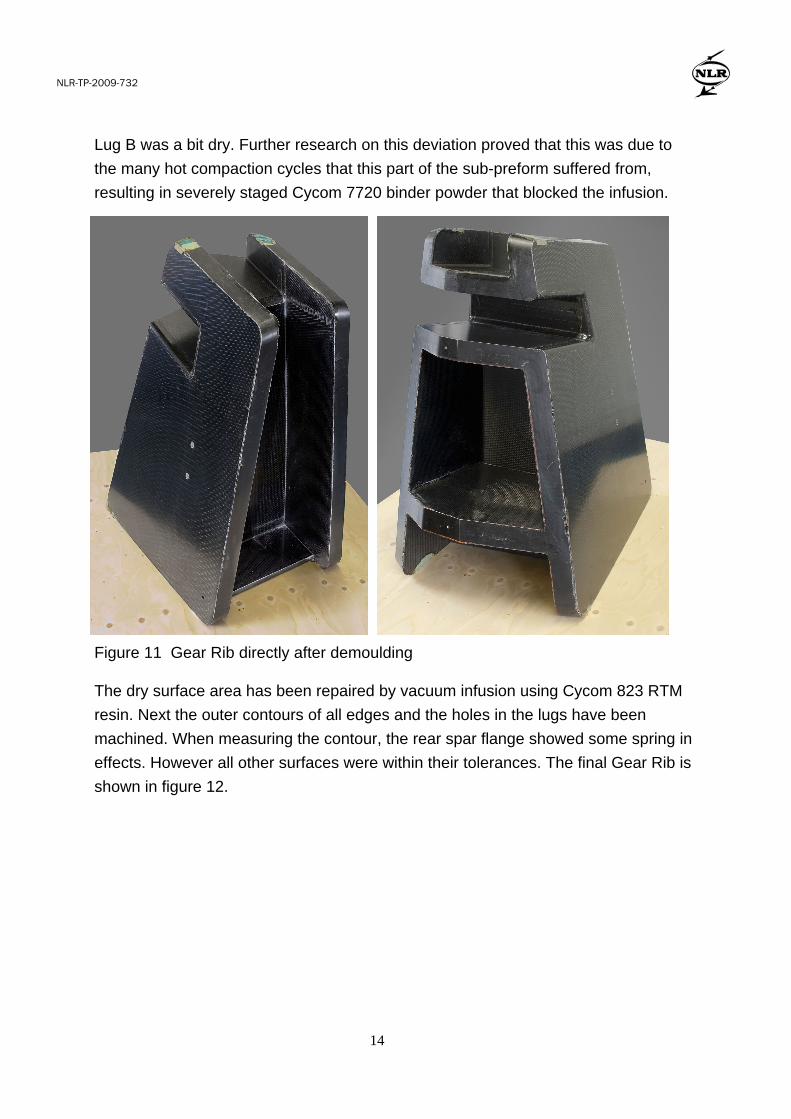
After demoulding of the component all surfaces except one came out very shiny, see
figure 11. The polymerisation shrinkage compensation worked well. However, the
surface of the first laminated plies on the tooling block in between Lug A and Forward
NLR-TP-2009-732
14
Lug B was a bit dry. Further research on this deviation proved that this was due to
the many hot compaction cycles that this part of the sub-preform suffered from,
resulting in severely staged Cycom 7720 binder powder that blocked the infusion.
The dry surface area has been repaired by vacuum infusion using Cycom 823 RTM
resin. Next the outer contours of all edges and the holes in the lugs have been
machined. When measuring the contour, the rear spar flange showed some spring in
effects. However all other surfaces were within their tolerances. The final Gear Rib is
shown in figure 12.
Figure 11 Gear Rib directly after demoulding

NLR-TP-2009-732
15
When looking at the program targets it must be concluded that the cost target (zero
increase) is not met. Obviously this is because all sub-preforms have been made
manually using a complex laminating method to prevent cuts in warp fibres at the
corners. However, recent developments in the field of dry fibre placement show that
the sub-preforms on the inner tooling blocks can be made with dry fibre placement
technology in the near future (ref. 9). This will improve the affordability of the
composite Gear Rib significantly.
Regarding the weight target unfortunately no direct comparison can be made since
no metallic A330 equivalent is available. This is because the gear architecture
selected for ALCAS differs significantly from the A330 gear architecture. One should
compare the entire assembly of Gear Rib, Rear Spar, Wing Upper Cover and Wing
Lower Cover instead of just the Gear Rib. However, this has not been done yet by
Airbus Operations Ltd.
The gear Rib will be assembled with the ALCAS composite lateral wing. The lateral
wing assembly will be tested end of 2010.
5. CONCLUSIONS
The ALCAS WP1 composite Gear Rib has been developed successfully using Cytec
Cycom 977-20/Priform materials and a RTM process. A tooling concept with oil
heated outer tooling and inner tooling blocks used for making sub-preforms and
hoisting/handling proved to work well and prevented excessive exothermal heat and
polymerisation shrinkage problems.
During preforming a novel laminating method has been applied to prevent cuts in the
warp fibres of the quasi UD fabric. The laminating method provided the required
mechanical properties in the corners of the component, but is too labour intensive to
Figure 12 Machined Gear Rib fitted with bushings

NLR-TP-2009-732
16
make the part affordable. However, recent developments in the field of dry fibre
placement show that the sub-preforms on the inner tooling blocks can be made with
dry fibre placement technology in the near future. Application of such automated
manufacturing technologies will be required to improve the affordability of large,
complex parts such as the composite Gear Rib. In case automated dry fibre preform
technologies are available serial production might be feasible.
In case of thick preforms that are made using many hot compaction stages, care
must be taken to prevent severe staging of the binder powder. In case of the ALCAS
Gear Rib the first plies on one inner tooling block have seen more than 25
compaction cycles, resulting in staged binder powder that blocked the infusion.
Acknowledgement
Special thanks to all ALCAS partners involved and especially to Airbus Operations
Ltd for their support during the development of the Gear Rib.
REFERENCES
1. J. Matthews, ALCAS Work Package Descriptions, ALCAS/01/00330/1/WP5/MEM,
2 February 2006
2. P. Nijhuis, Main landing gear support beam material selection and sub-component
manufacturing, NLR-CR-2006-130, National Aerospace Laboratory NLR,
Amsterdam, 2006.
3. M. Aldridge, Cycom 977-20 Soluble Fibre Technology Mechanical Property
Evaluation, CEM-Doc.-#02-018 Issue 1, Cytec Engineered Materials, 2002.
4 P. Nijhuis, Cycom 977-20/Priform design allowables, test report, NLR-CR-2008-
502, National Aerospace Laboratory NLR, Amsterdam, 2008.
5 L.J. Hart-Smith, Design and empirical analysis of bolted and riveted joints, F.L.
Matthews, Joining Fibre Reinforced Plastics, Elsevier Applied Science, London
UK, 1987.
6 H.G.S.J. Thuis, The development of a composite landing gear component for a
fighter aircraft, NLR-TP-2002-020, National Aerospace Laboratory NLR,
Amsterdam, 2002.
7 W.G.J. ‘t Hart and L.C. Ubels, Damage tolerance properties of carbon/epoxy lugs
made from Resin Transfer Moulded (RTM) plates, NLR-TP-2005-356, National
Aerospace Laboratory NLR, Amsterdam, 2005.
NLR-TP-2009-732
17
8 R.J.C. Creemers, P. Nijhuis, W. Wilson, M. Smeets, Transverse loads in thick
composite structures - a literature research, NLR-CR-2007-533, National
Aerospace Laboratory NLR, Amsterdam, 2007.
9 R. Klomp – de Boer, AUTOW: Automated Preform Fabrication by Dry Tow
Placement, ALCAS workshop leaflet, National Aerospace Laboratory NLR,
Amsterdam, 2009.