development of a methanol reformer for fuel cell...
TRANSCRIPT
Development of a methanol reformer for fuel cell vehicles
Bård Lindström
KTH-Kungliga Tekniska Högskolan Department of Chemical Engineering and Technology
Chemical Technology Stockholm 2003

PhD Thesis TRITA-KET R172
ISSN 1104-3466 ISRN KTH/KET/R-172-SE
ISBN 91-7283-406-4

To Amanda and my parents


Abstract Vehicles powered by fuel cells are from an environmental aspect superior to the traditional automobile using internal combustion of gasoline. Power systems which are based upon fuel cell technology require hydrogen for operation. The ideal fuel cell vehicle would operate on pure hydrogen stored on-board. However, storing hydrogen on-board the vehicle is currently not feasible for technical reasons. The hydrogen can be generated on-board using a liquid hydrogen carrier such as methanol and gasoline. The objective of the work presented in this thesis was to develop a catalytic hydrogen generator for automotive applications using methanol as the hydrogen carrier. The first part of this work gives an introduction to the field of methanol reforming and the properties of a fuel cell based power system. Paper I reviews the catalytic materials and processes available for producing hydrogen from methanol. The second part of this thesis consists of an experimental investigation of the influence of the catalyst composition, materials and process parameters on the activity and selectivity for the production of hydrogen from methanol. In Papers II-IV the influence of the support, carrier and operational parameters is studied. In Paper V an investigation of the catalytic properties is performed in an attempt to correlate material properties with performance of different catalysts. In the third part of the thesis an investigation is performed to elucidate whether it is possible to utilize oxidation of liquid methanol as a heat source for an automotive reformer. In the study which is presented in Paper VI a large series of catalytic materials are tested and we were able to minimize the noble metal content making the system more cost efficient. In the final part of this thesis the reformer prototype developed in the project is evaluated. The reformer which was constructed for serving a 5 kWe fuel cell had a high performance with near 100 % methanol conversion and CO concentrations below 1 vol% in the product stream. The results of this part are presented in Paper VII. Keywords: methanol, fuel cell, vehicle, catalyst, copper, hydrogen, on-board, steam reforming, partial oxidation, combined reforming, oxidative steam reforming, auto-thermal reforming, zinc, zirconium, chromium, aluminium oxide, manganese, characterization, temperature programmed reduction, X-ray diffraction, chemisorption, carbon monoxide, poisoning, reformer.

Sammanfattning Fordon med bränsleceller som drivkälla överträffar ur miljösynpunkt traditionella bilar utrustade med bensindrivna förbränningsmotorer. Elgenererande system baserade på bränslecellteknik behöver väte för driften. Det ideala bränslecellfordonet utnyttjar rent väte som lagras ombord. Emellertid är inte lagring ombord på fordonet utförbar på grund av tekniska skäl. Väte kan framställas ombord genom att använda en vätebärare som metanol och bensin. Målet för arbetet som presenteras i denna avhandling var att utveckla en katalytisk vätgasgenerator för mobila tillämpningar genom att använda metanol som vätebärare. Den första delen av arbetet ger en introduktion till området metanolreformering och egenskaperna hos ett bränslecellbaserat kraftsystem. Artikel I ger en kritisk översikt av katalytiska material och processer som är tillgängliga för att producera väte från metanol. Andra delen av denna avhandling består av en experimentell undersökning av inflytandet av katalysatorsammansättningen, material- och processparametrar på aktiviteten och selektiviteten för produktion av väte från metanol. I artikel II-IV studeras inflytandet av bärare, substrat och driftparametrar. I artikel V genomförs en undersökning av de katalytiska egenskaperna i ett försök att korrelera materialegenskaper med prestanda för olika katalysatorer. I den tredje delen av avhandlingen genomförs en undersökning för att belysa om det är möjligt att utnyttja oxidation av vätskeformig metanol som värmekälla för en automotiv reformer. I studien, som presenteras i artikel VI, testas en stor serie av katalytiska material och vi kunde minimera ädelmetallinnehållet vilket gör systemet mer kostnadseffektivt. I den sista delen av avhandlingen utvärderades reformerprototypen som utvecklats i projektet. Reformern som konstruerats för att betjäna en 5 kWe bränslecell hade hög prestanda med nära 100 % omsättning av metanol och CO-koncentrationer under 1 vol% i produktgasen. Resultaten från denna del är presenterade i artikel VII. Nyckelord: methanol, fuel cell, vehicle, catalyst, copper, hydrogen, on-board, steam reforming, partial oxidation, combined reforming, oxidative steam reforming, auto-thermal reforming, zinc, zirconium, chromium, aluminium oxide, manganese, characterization, temperature programmed reduction, X-ray diffraction, chemisorption, carbon monoxide, poisoning, reformer.

An expert is a person who has made all the mistakes that can be made in a very narrow field.
Niels Bohr


Publications referred to in this thesis The work presented in this thesis is based upon the following publications, referred to by their Roman numerals. The papers are appended at the end of the thesis I. Agrell, J., Lindström, B., Pettersson, L.J., and Järås, S.G. (2002).
Catalytic hydrogen generation from methanol, in Spivey, J.J. (Ed.), Catalysis – Specialist Periodical Reports, Royal Society of Chemistry, Cambridge, Vol. 16, pp. 67-132.
II. Lindström, B. and Pettersson, L.J. (2001). Hydrogen generation by steam
reforming of methanol over copper-based catalysts for fuel cell applications. Int. J. Hydrogen Energy 26, 923-33.
III. Lindström, B., Agrell, J., and Pettersson, L.J. (2002). Combined
reforming of methanol for hydrogen generation over monolithic catalysts. Chemical Engineering Journal (in press).
IV. Lindström, B. and Pettersson, L.J. (2002). Steam reforming of methanol
over copper-based monoliths: The effects of zirconia doping. J. Power Sources 106, 264-273.
V. Lindström, B., Pettersson, L.J., and Menon, P.G. (2002). Activity and characterization of Cu/Zn, Cu/Cr and Cu/Zr on γ-alumina for methanol reforming for fuel cell vehicles. Appl. Catal. A 234, 111-125.
VI. Lindström, B. and Pettersson, L.J. (2003). Catalytic oxidation of liquid
methanol as a heat source for an automotive reformer. Accepted for publication in Chemical Engineering and Technology.
VII. Lindström, B. and Pettersson, L.J. (2003). Design and development of an
auto-thermal reformer for fuel cell applications. Accepted for publication in Journal of Power Sources.

Other publications Other publications and conference papers on methanol reforming 1. Lindström, B. and Pettersson, L.J. (2001). Deactivation of copper-based
catalysts for fuel cell applications. Catal. Lett. 74, 27-30. 2. Lindström, B. and Pettersson, L.J. (2000). Steam reforming of methanol
for fuel cell applications. Proc. 9th Nordic Symposium on Catalysis, June 4-6, Lidingö, Sweden, p. 101-102.
3. Lindström, B. and Pettersson, L.J. (2000). A study of ethanol and
methanol as a fuel for onboard hydrogen generation by steam reforming on copper-based catalysts. Proc. XIII International Symposium on Alcohol Fuels, Stockholm, July 3-6, 2000.
4. Lindström, B. and Pettersson, L.J. (2000). Steam reforming of methanol
for automotive applications. Proc. 2000 Fuel Cell Seminar, Portland, Oregon, October 2000, pp. 325-328.
5. Lindström, B., Agrell, J., and Pettersson, L.J. (2001). Combinatorial
Reforming of Methanol for Hydrogen Generation over Monolithic Catalysts. Proc. 17th North American Catalysis Society Meeting, Toronto, June 3-8, 2001, p. 140.
6. Lindström, B. and Pettersson, L.J. (2001). Catalytic steam reforming of
methanol for automotive fuel cell applications. Proc. 5th European Congress on Catalysis (EUROPACAT 5), Limerick, Ireland, September 2-7, 2001.
7. Lindström, B. and Pettersson, L.J. (2001). Steam reforming of methanol
over copper-based monoliths: The effects of zirconia doping. Proc. 7th Grove Fuel Cell Symposium, London, September 11-13, 2001.
8. Lindström, B., Pettersson, L.J. and Menon, P.G. (2002). Influence of the
operating conditions on the performance of a methanol reformer. Proc. 10th Nordic Symposium on Catalysis, Helsingør, Denmark, June 2-4, 2002.

9. Pettersson, L.J. and Lindström, B. (2002). Catalytic fuel processing for fuel cell cars. Proc. Fourth International Tokyo Conference on Advanced Catalytic Science and Technology, Tokyo, July 14-19, 2002
10. Lindström, B. and Pettersson, L.J. (2002). Development of a methanol
fuelled reformer for fuel cell applications. Proc. Fuel Cells - Science and Technology 2002, Scientific Advances in Fuel Cell Systems, Amsterdam, 25-26 September, 2002.
11. Lindström, B. and Pettersson, L.J. (2002). Strategies for optimizing a
methanol reformer for fuel cell vehicles. Proc. XIV International Symposium on Alcohol Fuels, Phuket, Thailand, 12-15 November 2002.

1
1. Introduction.......................................................................................................3 1.1 Background..................................................................................................3 1.2 Fuel cell technology ....................................................................................5 1.3 Fuel strategies for mobile fuel cell applications..........................................6 1.4 Methanol production and application........................................................10
1.4.1 Manufacturing processes.....................................................................11 1.4.2 Synthesis gas sources ..........................................................................12 1.4.3 Methanol applications .........................................................................12 1.4.3 Health aspects......................................................................................13
1.5 Catalytic fuel processing ...........................................................................13 1.5.1 Decomposition ....................................................................................14 1.5.2 Steam reforming..................................................................................14 1.5.3 Partial oxidation ..................................................................................14 1.5.4 Combined reforming ...........................................................................15
1.6 Scope of the Thesis....................................................................................16 2. Properties of the system components of the methanol fuel cell propulsion system..................................................................................................................18
2.1 Introduction ...............................................................................................18 2.2 Fuel processor............................................................................................18
2.2.1 Catalytic reformer ...............................................................................19 2.2.2 Catalytic burner...................................................................................21 2.2.3 Evaporator ...........................................................................................21
2.3 Fuel cell .....................................................................................................21 2.4 Gas clean-up module .................................................................................23
2.4.1 Water-gas shift reaction ......................................................................23 2.4.2 Preferential oxidation..........................................................................24 2.4.3 Other clean-up processes ....................................................................24 2.4.4 Evaluation of the clean-up processes ..................................................25
2.5 Air module.................................................................................................25 3. Materials and processes for catalytic hydrogen generation from methanol (Paper I)...............................................................................................................26
3.1 Steam reforming ........................................................................................26 3.1.1 Catalytic materials for steam reforming of methanol .........................27
3.2 Partial oxidation.........................................................................................28 3.2.1. Catalytic materials for partial oxidation of methanol ........................29
3.3 Combined reforming .................................................................................30 3.4 Summary....................................................................................................31
4. Reforming catalyst and process optimisation (Papers II, III, IV and V .........32 4.1 Introduction ...............................................................................................32 4.2 Laboratory experimental set-up.................................................................32 4.3 Copper based materials for steam reforming of methanol (Paper II)........35
4.3.1 Background .........................................................................................35

2
4.3.2 Influence of the promoter on the activity and selectivity ...................35 4.4 Influence of the steam-to-methanol ratio on the catalytic activity of the steam reforming of methanol...........................................................................36 4.5 Copper-based materials for the combined reforming process (Paper III).38
4.5.1 Background .........................................................................................38 4.5.2 Influence of the promoter material on the combined methanol reforming process.........................................................................................39
4.6 Zirconia-doped catalysts for the steam reforming process (Paper IV) .....40 4.6.1 Background .........................................................................................40 4.6.2 Influence of zirconia-doping on the formation of CO for the steam reforming of methanol..................................................................................41
4.7 Characterization of copper-based catalysts for methanol reforming (Paper V) .....................................................................................................................42
4.7.1 Background .........................................................................................42 4.7.2 Influence of the surface properties on the catalytic activity ...............43
4.8 Summary....................................................................................................46 5. Catalytic oxidation of liquid methanol (paper VI) .........................................47
5.1 Introduction ...............................................................................................47 5.2 Experimental lab-scale set-up....................................................................47 5.3 Influence of catalyst material on the activity for methanol oxidation ......48 5.4 Summary....................................................................................................52
6. Development and evaluation of a catalytic reforming system (Paper VII) ....53 6.1 Introduction ...............................................................................................53 6.2 Experimental set-up...................................................................................53 6.3 Evaluation of laboratory tests....................................................................54 6.4 Industrial evaluation and optimisation of reformer prototype ..................58 6.5 Summary....................................................................................................59
7. Conclusions.....................................................................................................61 Acknowledgements.............................................................................................63 Nomenclature ......................................................................................................64 References ...........................................................................................................66

3
1. Introduction
1.1 Background Man has been walking the earth for more than 30 000 years and despite his intelligence and ingenuity he continued to do so for the first 25 000 years. The first forms of transportation which were constructed using the basic laws of mechanics can be traced back to the Sumerian civilization around 3500 B.C. [1,2]. The Sumerians developed simple forms of carriages that consisted of flat structures mounted on wheels that were pulled by either horses or men. The principles developed by the Sumerians were later employed by all major civilizations for more than 5000 years, and it was not until the middle of the eighteenth century that the first means of power driven transportation was constructed by the French engineer Nicolas Cugnot [2-4]. The original steam powered vehicle that Cugnot constructed in 1769, was developed for the French army to transport artillery (see Figure 1). Cugnot, however modified the vehicle one year later to carry passengers. Hence he created the first self-propelled road vehicle. Cugnot, however, ran out of money and his project was abandoned. Several attempts were made around the world to continue the development of the steam wagon. The low performance of the steam powered vehicle prevented it from being used commercially [4,5].
Figure 1: Cugnot´s steam powered road vehicle

4
During the nineteenth century several efforts were made to develop new fuels and engines for powering automobiles. The first real significant breakthrough came in 1876 when Nikolaus Otto and Eugen Langen invented the four-stroke engine (the Otto engine). It was, however, not until 1885 when Gottlieb Daimler invented the modern combustion engine, operating on gasoline injected through a carburettor, which was mounted on the first four-wheeled automobile [3,6]. The years that followed were characterized by the development and improvements of the automobile which culminated in 1908 when Henry Ford produced the first serially produced automobile, the T-Ford (see figure 2). The actual expansion of the auto market came, however, in the post World War 2 era, when the serially produced automobiles hit the European markets [6-8].
Figure 2: T-Ford
The environmental impacts of having an automobile in every home were never anticipated by the automakers in the early days of automotive manufacturing. There are a wide range of toxic substances emitted, from vehicles powered by the internal combustion engine, with different impacts on the environment. The pollutants emitted from automobiles today can be classified into two different categories: (i) substances emitted as unburned fuel pass through the engine and (ii) substances formed as by-products of the combustion [9,10]. The toxic substances which are inherent from the petroleum, such as benzene and non-aromatic hydrocarbons, are carcinogenic and have a direct impact on the health of humans when exposed to these substances. The pollutants that are produced in the internal combustion engine, such as nitrogen oxides (NOx), sulphur oxides (SOx) and carbon dioxide (CO2) have a long-term impact on the environment through acid rain and global warming [9,10].
5
The environment first came into focus in the early sixties when Rachel Carson’s “Silent spring” [11] sparked off the first real environmental debate. Demands from consumers and legislators prompted the automotive industry to reduce the pollutants emitted from their vehicles by changing the operating conditions in the combustion chamber and implementing exhaust gas catalysts. The actual impact that automobiles have on the environment has only started to become clear during the last decades as the result of serious smog related incidences, witnessed in cities with heavy traffic (especially Los Angeles and London), and observed global warming. The environmental effects of the modern automobile have impelled lawmakers around the world, particularly in California and the EU, to create emission regulations for automobiles [12]. The structure of the environmental regulations was constructed so that the limitations on the allowed emissions would increase over time. It is, however, not possible to reach the zero emission demands by modification of the internal combustion engine. This has prompted the automotive industry to search for viable replacements for the internal combustion engine. Automakers and legislators generally consider fuel cell based automobiles today as the most realistic alternative for replacing the internal combustion engine [13,14].
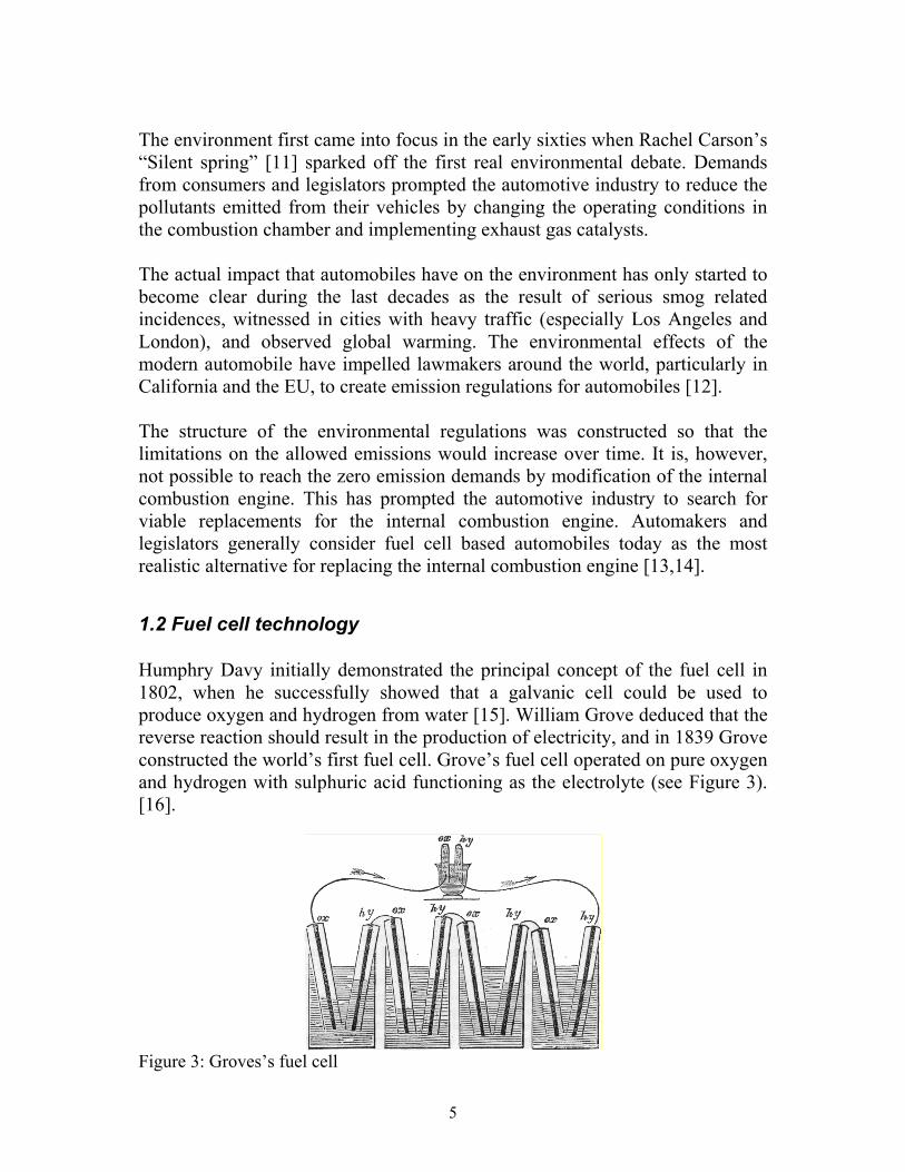
1.2 Fuel cell technology Humphry Davy initially demonstrated the principal concept of the fuel cell in 1802, when he successfully showed that a galvanic cell could be used to produce oxygen and hydrogen from water [15]. William Grove deduced that the reverse reaction should result in the production of electricity, and in 1839 Grove constructed the world’s first fuel cell. Grove’s fuel cell operated on pure oxygen and hydrogen with sulphuric acid functioning as the electrolyte (see Figure 3). [16].
Figure 3: Groves’s fuel cell
6
The path from Grove’s crude acidic fuel cell to modern polymer and solid oxide fuel cells is long, and a wide variety of fuel cells have been tested on the way. During the sixties the fuel cell concept received much attention, when alkaline fuel cells were successfully used in the Apollo space flights and scientists were predicting that the fuel cell would solve the energy problems of the world. Today fuel cells are seen as a realistic replacement for the internal combustion engine, with scientific evidence predicting the reduction of greenhouse gases by up to 68 % [17]. The type of fuel cell most likely to be used in automotive applications is the Polymer Electrolyte Fuel Cell (PEFC). The PEFC uses a Nafion™ (perfluorosulphonic acid polymer) type electrolyte and operates ideally at temperatures, 80-90 °C. The main drawbacks of the PEFC are that it has a low tolerance towards carbon monoxide (CO), is sensitive to temperature and expensive [18, 19]. The fuel cell operates by combining oxygen and hydrogen to form water while at the same time generating electricity and the most challenging task in mobile applications is how to provide the hydrogen. There are two main options available that both have their advantages and disadvantages: (i) Storing pure hydrogen in tanks or (ii) extracting the hydrogen on-board from an alternate hydrogen carrier. The available options are discussed in detail in the next section.
1.3 Fuel strategies for mobile fuel cell applications Fuel cell-based power systems require only hydrogen and oxygen (obtained from air) for operation, and the size and complexity of the system is directly dependent on the source and technology used for providing the hydrogen. For automotive applications the hydrogen can either be stored in pressurized tanks or generated on-board using a liquid hydrogen carrier such as methanol or gasoline [20-22]. The use of solid hydrogen carriers (metal hydrides) has also been proposed as an alternate storage form for hydrogen in automotive applications [23]. The physical properties of selected hydrogen carriers are listed in Table 1. From a technical aspect the storage of hydrogen in pressurized tanks is the most feasible solution as no intermediate step is required between the storage unit and the fuel cell. The use of pure hydrogen also eliminates the need for a clean-up unit required to remove by-products of a hydrogen generation process.

7
The use of pressurized hydrogen is however, currently not viable in automotive applications due to certain technological limitations such as:
• Limited driving range • The absence of an infrastructure for gaseous fuels • Logistic problems associated with refuelling • Hydrogen is highly flammable • Safety concerns
When using a hydrogen carrier, the hydrogen must be extracted from the fuel on-board by means of a suitable conversion process. The use of metal hydrides is currently unrealistic, as a fuel system based upon this technology would exceed the weight limitations of a fuel cell vehicle. Hydride systems also require a gaseous hydrogen refuelling system. Liquid fuels such as primary alcohols, gasoline and diesel are today favoured by the automotive industry as the most suitable hydrogen carriers for fuel cell vehicles. The two top contenders for the fuel cell market today are methanol and gasoline. From a technological point of view methanol is by far the most desirable fuel for several reasons:
• Conversion takes place at relatively low temperatures (250-300 °C) • High hydrogen to carbon ratio (4:1) • No C-C bond thus minimizing the risk of soot formation • Low formation of by-products (especially CO) • High hydrogen content in product stream (up to 75%) • No aromatics or sulphur in the fuel
The fuel cell is highly sensitive to impurities (especially CO) and for a system using gasoline in the feed a desulphurisation unit is required and the size of the gas clean-up module would also be significantly larger than for a system using methanol.

8
Tabl
e 1:
Fue
l pro
perti
es (a
dapt
ed fr
om D
icks
[23]
and
Lid
e [2
4])
H
ydro
gen
H2
Met
hane
C
H4
Am
mon
ia
NH
3 M
etha
nol
CH
3OH
Et
hano
l C
2H5O
H
Gas
olin
ea
C8H
18
Mol
ecul
ar w
eigh
t
2.02
16
.04
17.0
3 32
.04
46.0
7 11
4.2
Mel
ting
poin
t (°
C)
-259
.3
-182
.4
-77.
7 -9
7.6
-114
.1
-107
Boi
ling
poin
t (°C
)
-252
.9
-161
.5
-33.
4 64
.6
78.5
99
.2
Low
er h
eatin
g va
lue
at 2
5 °C
(k
J/m
ol)
241.
8 80
2.5
316.
3 63
8.5
1275
.9
5512
.0
Hea
t of
vapo
rizat
ion
at b
p (k
J/m
ol)
0.90
8.
19
23.3
35
.2
38.6
34
.4
Liqu
id d
ensi
ty
(kg/
m3 )
77-2
53 °C
42
3-162
°C
682-3
3.4
°C
79120
°C
78920
°C
69025
°C
Spec
ific
heat
at
25 °C
(J
mol
-1 K
-1)
28.8
35
.7
35.1
81
.1
112.
3 23
9.1

9
Flam
mab
ility
lim
its in
air
(%)
4 - 7
7 4
- 16
16 –
27
6 –
50
3 –
19
1 –
6
Aut
o ig
nitio
n te
mpe
ratu
re in
air
(°C
)
571
632
651
470
365
417
a G
asol
ine
is a
ble
nd o
f hyd
roca
rbon
s tha
t var
ies w
ith o
rigin
, pro
duce
r, ap
plic
atio
n an
d se
ason
. iso
-oct
ane
(2,2
,4-
trim
ethy
l pen
tane
) is a
reas
onab
le re
pres
enta
tive
of th
e ph
ysic
al p
rope
rties
.

10
Gasoline on the other hand, requires no modification of the infrastructure, although the gasoline used in fuel cell applications requires higher standards with respect to impurities (especially sulphur). Gasoline can also be used in both vehicles powered by the combustion engine as well as fuel cells, thus eliminating complications during a transition phase. The conversion of gasoline is complex and yields several by-products, which are harmful to the fuel cell and must be removed on-board increasing the cost of the fuel cell vehicle. By using methanol in the feed the emissions of NOx, CO, hydrocarbons and CO2 are reduced compared both to the Super Ultra Low Emission Vehicle (SULEV) standard set by the state of California and low sulphur gasoline fed fuel cell vehicles [25, 26]. The problems related with aromatics and sulphur in gasoline-based systems can be solved by using designed fuels manufactured by the Fischer-Tropsch synthesis. SASOL in South Africa is currently utilizing this method for manufacturing gasoline and diesel fuels. The concept of a multi-fuel reformer was discussed during the initial stage of the project, but was abandoned, as a system that is fuel flexible could never be optimised for all types of fuels. The fuel flexible system would as a result generate higher CO concentrations, which would require a larger gas-cleanup module, and thus increasing the cost and complexity of the system. The advantages of a fuel flexible system is that no changes in the current infrastructure would be required and the transition from internal combustion to fuel systems would be inexpensive We have therefore chosen methanol as the hydrogen carrier as it is the most suitable fuel from both a technological and environmental perspective. The performance of the reforming system is dependent on the process used to extract the hydrogen from the methanol and the process alternatives and their properties are presented in section 1.5. Details of the commercial production and applications of methanol are presented in the next section.
1.4 Methanol production and application Methanol (Methyl alcohol) is a primary alcohol that can be manufactured from a wide variety of sources and has an equally wide variety of applications. Methanol is found as a colourless liquid at room temperature and is recognized by its mild characteristic alcohol odour [27, 28]. Methanol has traditionally been used as a solvent or feedstock for bulk chemicals (especially formaldehyde and
11
MTBE). With the growing interest in fuel cell applications the role of methanol is however expected to change from only serving as a bulk chemical to a commodity product.
1.4.1 Manufacturing processes Methanol was originally known as wood alcohol as it was originally produced by the dry distillation of wood. Today methanol is mainly produced from synthesis gas, a mixture of CO and H2. A brief discussion of the available manufacturing methods will be presented here: Extraction from natural sources Methanol can be extracted from several types of plants and woods, which served as the only commercial source of methanol production until the introduction of the synthetic process in 1923 [29, 30]. The extraction process is based upon thermal decomposition (i.e. pyrolysis) of hardwoods, such as birch and oak, in the absence of air at temperatures between 160-450 °C. The earliest reference to this process is found in Boyle´s “Sceptical Chymist” from 1661 [31]. The decomposition generates a large mixture of products, in addition to methanol significant quantities of charcoal, tar, methanoic acid and acetone. The methanol yield is also low, (1-2 %) for hardwoods and even lower for softwoods. Therefore this process is unsuitable for commercial applications [29, 30]. Fermentation The production of methanol in plants and living organisms takes place by a process known as fermentation. Fermentation can be described as the decomposition of complex organic materials by bacteria to methanol. This process is similar to the fermentation of carbohydrates to ethanol. There are currently no solutions available for commercialisation of this technology [29]. Synthetic production The realization that methanol could be produced from inorganic compounds came first in 1905, when the French scientist Paul Sabatier proposed that methanol could be synthesized by hydrogenation of CO. The first commercial process was established in 1923 by BASF in Leuna, Germany [29, 32, 33]. The process which used a zinc-chromium catalyst was developed upon the basic

12
principals of the ammonia synthesis. The low activity of the catalyst implied that the process had to be operated at elevated temperature and pressures (T=320-450 °C, P=250-350 atm). The thermodynamics are also favoured by operation at high pressures. The high pressure process dominated the market until 1960 when ICI developed a highly active copper-zinc catalyst which could operate at pressures below 100 atm. The copper-zinc based catalysts are still today dominant for the production of methanol from synthesis gas (syngas) [29, 34].
1.4.2 Synthesis gas sources All hydrocarbons that can be converted into synthesis gas either through steam reforming (equation 1) or gasification with oxygen (equation 2) are potential sources for commercial production of methanol. [27, 28, 32] CnHm + n H2O n CO + (n + m/2) H2 (1) CnHm + (n/2) O2 n CO + m/2 H2 (2) Steam reforming of natural gas today accounts for more than 80 % of the world’s production of methanol. The steam reforming reaction is usually performed over a nickel based catalyst in an endothermic reactor. The methanol synthesis catalysts are sensitive to sulphur-based compounds which have to be removed prior to the reforming, thus methanol produced from steam reforming is redundant of sulphur and thereby the potential of methanol as a fuel for fuel cell-based applications is increased. [32,35,36]
1.4.3 Methanol applications The world’s production capacity of methanol today exceeds more than 32,575,000 metric tons with production facilities in more than 30 countries (see figure 4). [37]

13
Figure 4: World wide methanol production capacity Methanol is today mainly used as a solvent and as a bulk chemical for the production of formaldehyde and MTBE. [37]
1.4.3 Health aspects The most common question raised today regarding the suitability of methanol as a fuel, is how toxic methanol really is. The answer to this question is simple: Yes, methanol is poisonous and as with many other fuels it is highly toxic if taken orally. Caution should be taken, however there is no need to increase level of caution used for petroleum today. It should however be noted that the body can metabolise low concentrations of methanol with no ill effects. [38]
1.5 Catalytic fuel processing The generation of hydrogen from methanol is possible through several process alternatives: decomposition, steam reforming, partial oxidation and a combination of steam reforming and partial oxidation. The combined reforming process is often referred to as auto-thermal reforming when operated under thermally neutral conditions [39].
Capacity (Metric tonnes)
5545000, 16%
7798000, 22%
6750000, 19%
7791000, 22%
7391000, 21%
North America South America Europe Middle East/AfricaAsia/Pacific
14
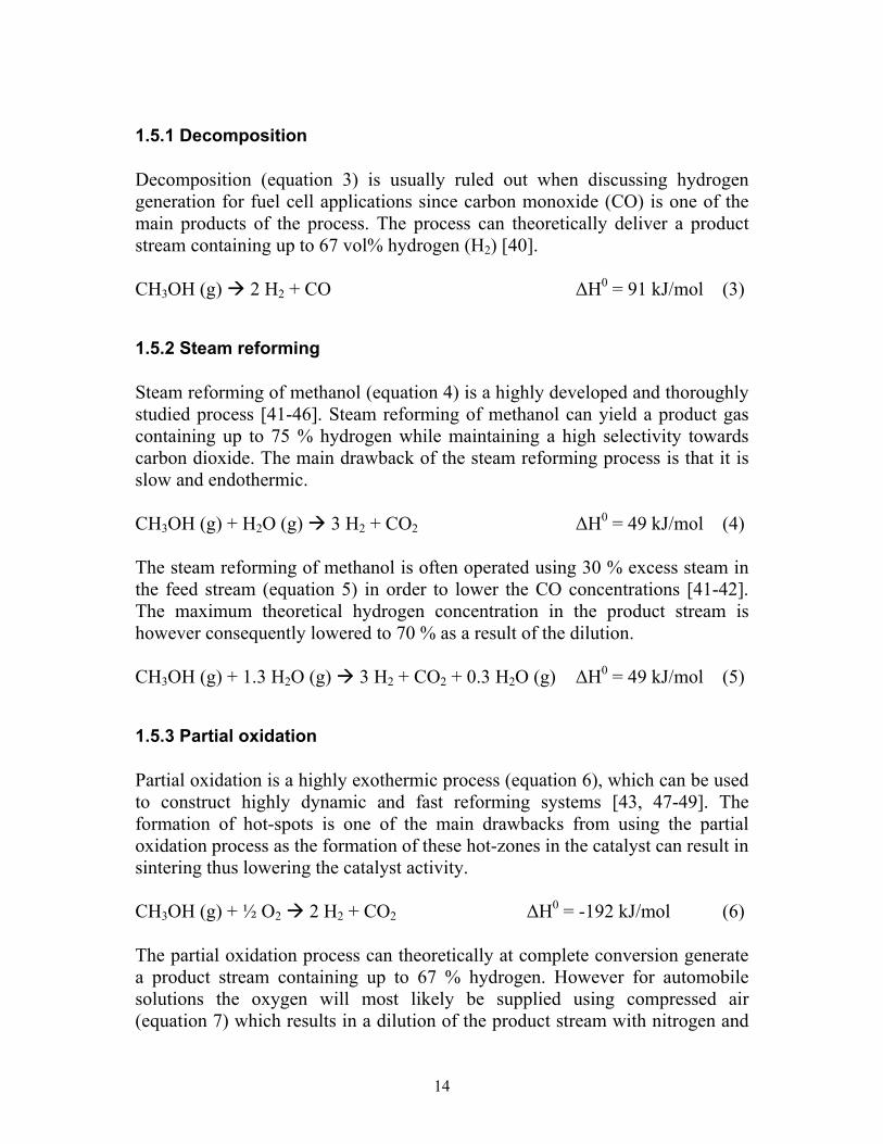
1.5.1 Decomposition Decomposition (equation 3) is usually ruled out when discussing hydrogen generation for fuel cell applications since carbon monoxide (CO) is one of the main products of the process. The process can theoretically deliver a product stream containing up to 67 vol% hydrogen (H2) [40]. CH3OH (g) 2 H2 + CO ∆H0 = 91 kJ/mol (3)
1.5.2 Steam reforming Steam reforming of methanol (equation 4) is a highly developed and thoroughly studied process [41-46]. Steam reforming of methanol can yield a product gas containing up to 75 % hydrogen while maintaining a high selectivity towards carbon dioxide. The main drawback of the steam reforming process is that it is slow and endothermic. CH3OH (g) + H2O (g) 3 H2 + CO2 ∆H0 = 49 kJ/mol (4) The steam reforming of methanol is often operated using 30 % excess steam in the feed stream (equation 5) in order to lower the CO concentrations [41-42]. The maximum theoretical hydrogen concentration in the product stream is however consequently lowered to 70 % as a result of the dilution. CH3OH (g) + 1.3 H2O (g) 3 H2 + CO2 + 0.3 H2O (g) ∆H0 = 49 kJ/mol (5)
1.5.3 Partial oxidation Partial oxidation is a highly exothermic process (equation 6), which can be used to construct highly dynamic and fast reforming systems [43, 47-49]. The formation of hot-spots is one of the main drawbacks from using the partial oxidation process as the formation of these hot-zones in the catalyst can result in sintering thus lowering the catalyst activity. CH3OH (g) + ½ O2 2 H2 + CO2 ∆H0 = -192 kJ/mol (6) The partial oxidation process can theoretically at complete conversion generate a product stream containing up to 67 % hydrogen. However for automobile solutions the oxygen will most likely be supplied using compressed air (equation 7) which results in a dilution of the product stream with nitrogen and

15
subsequently lowering the maximum hydrogen concentration to 41 %. The performance of the fuel cell is dependent on the hydrogen concentration and therefore operating the reformer with only partial oxidation may not be suitable [19]. CH3OH (g) + ½ O2 + 1,88 N2 2 H2 + CO2 + 1,88 N2 ∆H0 = -192 kJ/mol (7)
1.5.4 Combined reforming By combining partial oxidation and steam reforming (equation 8) it is possible to obtain a system which is dynamic while generating relatively high hydrogen concentrations [17,43,50-53] as well as avoiding the formation of hot-spots in the catalyst bed. When operating the combined process under stoichiometric conditions the sum of the molar coefficients of water (x) and oxygen (y) equals the coefficient of methanol (x + y =1). CH3OH (g) + x H2O (g) + ½ y O2 (3x +2y) H2 + CO2 ∆H0=49x-192y kJ/mol (8) The maximum theoretical hydrogen concentration is dependent on the oxygen to methanol ratio, OMR (mole oxygen / mole methanol), as shown in Figure 5. When operating under stoichiometric conditions x + y = 1. The thermal nature of the process is also dependent on the OMR as illustrated in Figure 5. For automotive solutions the oxygen would even for the combined process be supplied as compressed air and the system would also operate using 30 % excess water to lower the formation of carbon monoxide (Equation 9) [41, 42]. CH3OH + 1,3x H2O + ½ y O2 + 1,88y N2 (3x +2y) H2 + CO2 + 1,88y N2 + 0,3x H2O (9) The dependence of the hydrogen concentration on the OMR for the combined process using air in the feed is illustrated in Figure 5.

16
Figure 5: Influence of oxygen-to-methanol ratio on hydrogen concentrations
1.6 Scope of the Thesis The present study was part of the activities within the framework of the Swedish Energy Agency programme “Energy Systems for Road Vehicles” Project no P10792-2 (1998-2003). The work at the Royal Institute of Technology focused on the development of catalysts and catalytic systems for automotive reforming. Laboratory tests were performed in collaboration with the Volvo Technology Corporation in order to ensure that the reformer met the industrial standards of an automotive reformer. The purpose of the work presented here was to develop and test catalysts for catalytic hydrogen generation from methanol, as well as to develop a methanol reformer capable of serving a 5 kWe fuel cell. Emphasis was placed on designing a self-sustaining reformer (avoiding electrical heating), with low start-up times and low concentrations of carbon monoxide. A catalytic system for igniting liquid methanol for an internal heat exchange system for the reformer was also developed. For the reforming system pellet-based catalysts and monolithic catalysts were tested. The γ-alumina pellets used in all experiments were provided by SASOL Germany and the cordierite monoliths were from DOW Corning. The catalysts were impregnated with various base metals supported on γ-alumina (γ-Al2O3). The influences of the operating parameters were also studied in great detail in order to obtain a system that has a high activity and selectivity. For the oxidation system a mixture of base metal oxides and noble metals were studied.
17
We have also used various characterization techniques in order to improve the understanding of the structural and chemical properties of the catalysts. The characterization methods used in this study were: Temperature Programmed Reduction (TPR), Temperature Programmed Oxidation (TPO), Pulse Chemisorption, X-ray diffraction, BET-Surface area analysis and Scanning Electron Microscopy (SEM). The thesis consists of 7 papers and a main section where the results from the papers have been summarized in four chapters: “Materials and processes for catalytic hydrogen generation from methanol”, “Reforming catalyst and process optimisation”, “catalytic oxidation of liquid methanol” and “Development and evaluation of a catalytic reforming system” Specifics regarding the preparation methods, characterization techniques and operating parameters are described in detail in the papers. Paper I is a review describing the various methods and materials used for catalytic hydrogen generation from methanol. The paper presents detailed descriptions of the materials used as well as a detailed account of proposed mechanisms for the various processes available for converting methanol into hydrogen. Included in the paper is also an analysis of the current industrial activities in the field of automotive reforming. Papers II-V present investigations of the influence of the catalytic material and operating conditions on the activity and selectivity for methanol reforming. The influence of applying a promoter with the active phase as well as the influence of the substrate properties is also studied. Paper VI deals with the problems of igniting liquid methanol at room temperature. In this paper a novel reactor system designed at the Royal Institute of Technology is presented. The paper also includes a catalytic study, where various materials are tested. Paper VII presents the reformer prototype developed in our laboratory, focusing on reducing start-up times and CO concentrations.

18
2. Properties of the system components of the methanol fuel cell propulsion system
2.1 Introduction The fuel cell-based engine is a complete power solution that can easily be incorporated into a wide range of vehicle and stationary platforms. When describing the methanol fuel cell (MFC) propulsion system it is convenient to divide the system into a number of interacting functional modules, where the overall performance of the system is dependent on the compatibility and performance of the individual modules. The main modules of the MFC propulsion system are:
• Fuel processor • Gas clean-up • Air module • Fuel cell module
When designing the individual modules there are several criteria that have to be met with respect to cost and performance. The US Department of Energy (DOE) and the automotive industry have together developed a series of criteria for all of the modules in a fuel cell vehicle (FCV). These criteria were considered when we designed the fuel processor [54]. The properties and functions of the individual modules will now be discussed in detail. The main focus of this chapter is placed on the fuel processor, as the objective of my thesis was to develop a compact methanol reformer for fuel cell vehicles. A brief schematic of the MFC propulsion system is shown in Figure 6.
2.2 Fuel processor The role of the fuel processor is to extract clean hydrogen from a hydrogen carrier (in our case methanol). When designing an on-board fuel processor there are several key requirements which have to be fulfilled [54, 55]
• The processor must be compact and light, due to the limited space in automobiles where the weight of the vehicle sets the power requirements

19
• The reformed gas must contain low concentrations of by-products as the fuel cell has a low tolerance to impurities and the size and weight of the clean-up module is proportional to the by-product concentration
• The system must have a short start-up time • The system must be highly responsive to changes in the hydrogen
demand The fuel processing module consists of three separate units: catalytic reformer, catalytic burner, and evaporator. Detailed descriptions of the units are outlined in the following sections.
2.2.1 Catalytic reformer The size and weight of the fuel cell system is ultimately dependent on the performance of the fuel processor and it is therefore vital that every aspect of the fuel processor is optimised. The fuel processing system is usually designed around the catalytic reformer, translating the performance demands of the fuel processor onto the reforming catalyst [54, 55]. Reforming catalyst requirements:
• High activity in order to obtain a compact and light reformer • High selectivity to minimize the size of the clean-up module • Low temperature operation to minimize start-up time • Robust –The catalyst must withstand mechanical stress • Long life • Thermally resistant • Low cost
The development of reforming catalysts is described in detail in Chapter 4 and Papers II-V.

20
Figu
re 6
: MFC
pro
puls
ion
syst
em

21
There are several process alternatives available for converting methanol into hydrogen that can be implemented in an automotive reformer. The choice of process and operating conditions greatly influences the performance of the fuel cell system and thus process optimisation is vital for the construction of a functional FCV. Detailed descriptions of the process alternatives are presented in Chapter 3.
2.2.2 Catalytic burner The exploitable energy surplus in a fuel cell vehicle is low and therefore one of the most important tasks is to provide the heat required for the evaporation and conversion of methanol and water. The most viable solution is to provide the energy through indirect heat transfer with a catalytic burner. The catalytic burner must be designed to consume methanol during start-up and unreacted hydrogen during normal operation, as there is no energy surplus available for electrical heating during start-up. These harsh operational criteria increases the performance demands of the catalytic burner as it must therefore be designed to handle oxidation and evaporation of liquid methanol as well as of hydrogen. The performance criteria described for the reforming catalysts are also applicable to the oxidation catalyst. The catalytic burner and the oxidation catalysts developed in this project are described in detail in Chapter 5 and Paper VI.
2.2.3 Evaporator The evaporator utilizes indirect heat exchange with the catalytic burner and simultaneously vaporises methanol and water. A detailed description of the vaporising unit developed in this project can be found in Chapter 6.
2.3 Fuel cell The fuel cell operates by electrochemical oxidation of hydrogen to form water while generating electricity (see Figure 7) [23]. The electrochemical reactions which take place on the catalytic surfaces of the anode and cathode can be illustrated by the following reactions:

22
Anode: 2 H2 4 H+ + 4e- (10) Cathode: O2 + 4e- + 4H+ 2 H2O (11)
Figure 7: Fuel cell schematic At the anode the hydrogen is ionised, releasing electrons while generating protons. The hydrogen ions are transported through the membrane and at the cathode oxygen reacts with the electrons and protons (produced at the anode) to form water. The cathodic reaction is exothermic, releasing energy which has to be removed by a coolant (see Figure 6). The polymer electrolyte fuel cell (PEFC) used in automotive applications is highly sensitive to poisoning especially by carbon monoxide, which may significantly lower the performance of the fuel cell at concentrations above 50 ppm [18, 19]. The performance of the system is also dependent on the hydrogen concentration of the reformed gas and thus it is favourable to select a hydrogen generation process with a high hydrogen production capacity.

23
2.4 Gas clean-up module There are two main processes which are considered for removing by-products from the reformed gas in methanol fuel cell vehicles: Water-gas shift and preferential oxidation. The processes are usually combined in series for optimal results with respect to activity and selectivity.
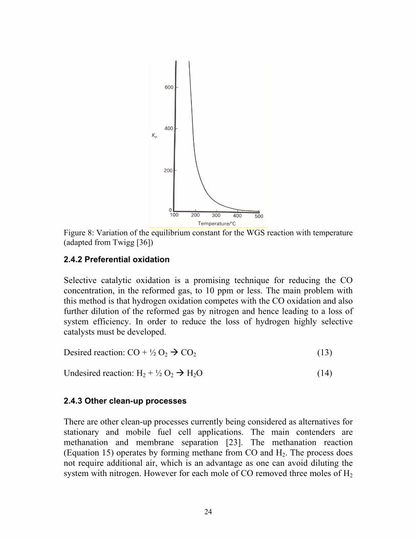
2.4.1 Water-gas shift reaction The water-gas shift (WGS) reaction (Equation 12) is an important aspect of automotive reforming as it involves the removal of carbon monoxide (CO) from the product stream [36]. The shift step can either be used as a separate clean-up step or as part of the reforming process which is the main reason for running the steam reforming and the combined reforming steps with excess steam. The maximum theoretical hydrogen concentration for the steam reforming and combined reforming processes is also dependent on the formation of carbon monoxide (CO), as the decomposition process yields lower H2 concentrations (67 %) than the combined and steam reforming processes The WGS reaction, shown in Equation 12 below, is slightly exothermic and hence its equilibrium constant decreases with temperature (see Figure 8) and as a result the equilibrium conversion decreases with increasing temperature. CO + H2O (g) H2 + CO2 ∆H0 = -41 kJ/mol (12) The efficiency of the WGS process can be improved by operating the reforming process with excess steam [36].
24
Figure 8: Variation of the equilibrium constant for the WGS reaction with temperature (adapted from Twigg [36])
2.4.2 Preferential oxidation Selective catalytic oxidation is a promising technique for reducing the CO concentration, in the reformed gas, to 10 ppm or less. The main problem with this method is that hydrogen oxidation competes with the CO oxidation and also further dilution of the reformed gas by nitrogen and hence leading to a loss of system efficiency. In order to reduce the loss of hydrogen highly selective catalysts must be developed. Desired reaction: CO + ½ O2 CO2 (13) Undesired reaction: H2 + ½ O2 H2O (14)
2.4.3 Other clean-up processes There are other clean-up processes currently being considered as alternatives for stationary and mobile fuel cell applications. The main contenders are methanation and membrane separation [23]. The methanation reaction (Equation 15) operates by forming methane from CO and H2. The process does not require additional air, which is an advantage as one can avoid diluting the system with nitrogen. However for each mole of CO removed three moles of H2

25
is consumed making the process unsuitable for automotive fuel cell applications. CO + 3 H2 CH4 + H2O (g) ∆H0 = -206 kJ/mol (15) Membrane technology is a method which can separate CO from H2 without decreasing the H2 concentration in the stream. The technology requires high pressure which is energy consuming and currently the membranes are based upon Pd making the system expensive and not feasible for automotive applications.
2.4.4 Evaluation of the clean-up processes The WGS reactor utilizes excess water from the reformer to convert CO to CO2 while generating H2, and therefore increasing the overall performance of the system. The PROX reactor removes CO by oxidation, however the process is not 100 % selective and so the hydrogen content is reduced during this clean-up step. The PROX process also utilizes air to supply the required oxygen which implies that the reformed gas is diluted with nitrogen and thus lowering the overall performance of the system. In order to obtain optimal results from the fuel cell system, utilization of the WGS reaction should be maximized in order to avoid lowering of the hydrogen content during the gas clean-up.
2.5 Air module Oxygen is required for the operation of the fuel cell system and has to be transported all around the MFC system. Compressing ambient air to the operating pressure of the fuel cell provides the oxygen. Some of the air is required for the operation of the preferential oxidizer and the combustor and is compressed further in a secondary compressor. It is also vital that impurities are separated by filters and that each module is fed with exact concentrations. The modules that require oxygen are:
• Fuel cell • PROX reactor • Catalytic burner • Reformer
26
3. Materials and processes for catalytic hydrogen generation from methanol (Paper I) Catalytic production of hydrogen from methanol has been studied for the last 30-40 years, and decomposition of methanol to carbon monoxide (CO) and hydrogen (H2) has been utilized commercially by the steel industry for decades as a method for providing carbon monoxide for the carbonisation of steel. Catalytic hydrogen generation by decomposition of methanol received much attention during the eighties when a significant amount of investigations for using decomposed methanol for improving efficiency and decreasing emissions from internal combustion engines as well as improving the cold start of alcohol engines were performed [40]. The decomposition process is however unsuitable for fuel cell applications as CO is one of the main products, which has detrimental effects on the fuel cell. The processes that are most feasible for on-board production of hydrogen from methanol for fuel cell applications are: steam reforming, partial oxidation and combined reforming. In this chapter catalytic materials and processes for extracting hydrogen from methanol for fuel cell applications will be discussed in detail.
3.1 Steam reforming Steam reforming (equation 4) of methanol (SRM) is a well-developed and commercialised process. The process is usually carried out over copper-based catalysts [41, 42, 59-70], however there has been some attention given to Group 8-10 metals as well [71-73]. CH3OH + H2O 3 H2 + CO2 (4) Steam reforming can under favourable conditions generate a product stream containing 75 % H2 and 25 % CO2 on a dry basis. The high H2 production capacity of steam reforming is the main argument for choosing steam reforming over partial oxidation, which can only produce up to 41 % when air is used to supply the oxygen. The high-energy requirement of the steam reforming process is a major obstacle for the implementation of a reformer based upon this process in an automotive application. There are however several commercial solutions available that are

27
based upon steam reforming [74]. The influence of the catalytic material on the SRM will now be discussed in detail.
3.1.1 Catalytic materials for steam reforming of methanol The kinetics and reaction paths for the SRM is dependent on the catalytic materials used, therefore the discussion is divided into two parts: (i) Traditional copper-based catalysts supported on γ-alumina and (ii) materials containing other transition metals supported on various oxides. Copper-based catalysts There are two major pathways suggested in the literature for SRM over copper-based catalysts: (i) a decomposition-water-gas shift (WGS) sequence and (ii) methanol dehydrogenation over methyl formate. The decomposition-WGS pathway (below) is considered to take place as a sequence. Initially methanol decomposes to CO and H2 and then the CO reacts further with water to form CO2 and H2. CH3OH CO + 2 H2 CO + H2O CO2 + H2 CH3OH + H2O CO2 + 3 H2 This mechanism has been accepted by several authors [42, 60-62, 68] and has been studied significantly over both commercial and novel catalysts [60-62]. The methyl formate reaction route has been shown to be dependent on the support, and that no CO was formed and that methyl formate and formic acid are the only intermediates [41]. The suggested reaction path over γ-alumina was as follows [63, 68, 71]: 2 CH3OH CH3OCHO + 2 H2 CH3OCHO + H2O HCOOH + CH3OH HCOOH CO2 + H2 CH3OH + H2O CO2 + 3 H2 The formation of by-products for steam reforming over copper-based catalysts is generally low. The formation of products such as CO, formic acid and methyl

28
formate (which has been observed by some researchers [63, 67, 71]) is significant as it poses a threat to the performance of the fuel cell. Operating the SRM with excess steam and thereby integrating the WGS reaction into the reformer can minimize the formation of CO. Other transition metal-based catalysts The catalytic properties of copper for SRM are significantly different from other transition metals. Several investigations have been performed on the behaviour of Group 9-10 transition metals on the conversion of alcohols [70, 71]. Table 2 lists some examples of catalytic materials tested for SRM found in literature Table 2: Group 9-10 catalytic materials used for SRM Active phase Support Support Pd Al2O3 Cr2O3 Pt SiO2 La2O3 Ni ZrO2 MnO2 Rh ZnO MgO The major difference between copper and other transition metals is the CO2 selectivity. Several investigations [71-73] showed that CO concentrations up to 25 % could be achieved during SRM, results comparable to decomposition. The influence of the support was shown to be significant. The high CO concentrations obtained for these transition metals makes them highly unsuitable for fuel cell applications.
3.2 Partial oxidation The production of H2-rich gases with low CO concentrations from methanol was until the middle of the eighties solely done by steam reforming. The high endothermic nature of the steam reforming reaction led researchers to search for alternate methods for generating CO free hydrogen. Partial oxidation (equation 6) of methanol (POM) offers several advantages over steam reforming. The reaction is exothermic (i.e. thermodynamically favourable) and requires only air as an oxidant and displays higher reaction rates than steam reforming. Theoretically POM can generate a product stream containing up to 67 % H2, however in automotive applications the oxygen will most likely be provided from compressed air reducing the theoretical H2 maximum to 41 %.

29
CH3OH + ½ O2 2 H2 + CO2 (6) The influence of the catalytic material on the POM reaction will now be discussed in detail.
3.2.1. Catalytic materials for partial oxidation of methanol An investigation of the current literature showed that two types of catalysts were favoured for the POM reaction: copper and palladium. The catalytic properties of these materials show significant discrepancies with respect to by-product formation and the effect of oxygen partial pressure. The Cu-based catalysts display high selectivities for the POM reaction whereas for the Pd-based catalysts the CO concentration is quite significant. The materials will for these reasons be discussed separately. Copper-based catalysts The reaction path for POM over Cu-based catalysts is quite complex. Several reactions have been observed which are catalysed by copper, e.g. steam reforming, partial oxidation, decomposition, WGS and total oxidation [47-50, 75-80]. The selectivity for H2 formation over Cu-based catalysts has been shown to have a strong dependence on the methanol conversion, suggesting that the oxidation and reforming takes place consecutively [47,48,75-80]. Formaldehyde has been found as an intermediate of the POM reaction over Cu-based catalysts and by studying the formation of formaldehyde and the subsequent decomposition into CO and H2. Investigations have also shown that when operating POM under fuel-rich conditions a product mixture containing formaldehyde, CO and H2 was produced. There are several studies that indicate that the POM reaction involves SRM and decomposition. Huang and Wang [81] proposed the following mechanism: CH3OH + ½ O2 H2 + CO + H2O CH3OH CO + 2 H2 CO + H2O CO2 + H2 Which in essence suggests that partial oxidation consists of all of the reactions above, while the conventional steam reforming is reported to only consist of

30
decomposition and WGS. Based upon this results we may draw the conclusion that steam reforming is part of the partial oxidation scheme. There are several by-products that may be formed in the POM reaction, apart from unreacted methanol and CO results have shown that dimethyl ether (DME), formic acid, formaldehyde and methane are possible [81]. The activity and selectivity of the POM is strongly influenced by the reaction temperature. The conversion of methanol increases with temperature, whereas the CO2 selectivity decreases. The copper-zinc based catalyst is known to deactivate quickly during operation, however using an alumina support can stabilize the material at the cost of lower activity. Palladium-based catalysts The activity of Group 10 metals, such as palladium and platinum, are active for the conversion of methanol. However they are much less selective than the copper-based catalysts described in the previous section, yielding primary the decomposition products [71-73]. This catalytic property makes them less feasible for fuel cell applications. The only exception found was for Pd/ZnO which showed selectivity close to that of copper [70].
3.3 Combined reforming The idea of combining steam reforming with partial oxidation was first initiated by Huang and Wang in 1986 [81] who proposed a new reaction route for producing H2 from methanol. The combined reforming reaction (equation 8) provides a method for producing relatively high hydrogen selectivities and low CO concentrations while maintaining a dynamic system. CH3OH (g) + x H2O (g) + ½ y O2 (3x +2y) H2 + CO2 (8) When operating the combined process under stoichiometric conditions the sum of coefficients of water (x) and oxygen (y) equals the molar coefficient of methanol (x + y =1). The combined reforming reaction can be operated under endothermic, exothermic or thermally neutral conditions, dependent on the chosen oxygen-to-methanol ratio. The number of research groups focusing on combined reforming has rapidly increased during the past years as well as the number of publications. [17, 43, 50-53, 81, III] The main by-product for the combined

31
reforming reaction has been shown to be CO, however there has been some observations of methyl formate and formic acid [50, 81]. The materials used during the combined reforming reaction are mainly the copper-based materials used for the steam reforming and partial oxidation reactions and detailed descriptions of these materials are presented in sections 3.1.1 and 3.2.1
3.4 Summary The literature reviewed in Paper I clearly indicates that methanol reforming catalysts should contain copper in order to obtain high activity and low CO concentration in the product stream. The Pt group metals were observed to generate mainly the decomposition products which make them unsuitable for methanol reforming.

32
4. Reforming catalyst and process optimisation (Papers II, III, IV and V)
4.1 Introduction From the results presented in chapter 3 it is evident that, regardless of the operating conditions, the catalysts used for catalytic reforming of methanol should contain copper. The role of the support and promoter as well as the influence of the structural and surface properties of the catalyst on the catalytic activity and selectivity is discussed in detail in this chapter. The impact of the operating conditions on the activity and product distribution is also discussed in this chapter.
4.2 Laboratory experimental set-up The activity test was performed in a reactor system developed completely in-house at our own laboratory. When we constructed the reactor system for the catalytic screening, several design criteria were set in order to obtain a flexible reactor system:
(i) The catalytic reactor should be multifunctional with respect to the form and shape of the catalyst (i.e. powders, pellets and monoliths)
(ii) The fuels should be completely vaporised and mixed prior to entering the reactor in order to avoid fuel rich zones which could cause transient CO levels
(iii) Temperature control of the reactants should be maintained in a pre-heater to enable varying the temperature of the reactants prior to entering the reactor
(iv) Strict temperature control over the entire catalytic reactor (v) The reactor system must be process flexible in order to enable study of
steam reforming, partial oxidation and combined reforming at various oxygen-to-methanol ratios and steam-to-methanol ratios.
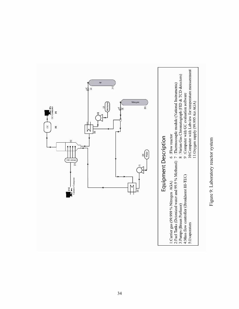
The reactor system constructed for this project (see Figure 9) utilizes liquid methanol and water, which are evaporated in separate evaporators prior to entering the mixing chamber. The reactor was made of stainless steel (ASTM 316) with an inner diameter of 25 mm. The product stream composition was measured on-line with a gas chromatograph from Varian equipped with both a thermal conductivity detector (TCD) and a flame ionisation detector (FID). The
33
reactor temperature was measured with thermocouples (type K) connected to a LabView ™ based measuring system developed at our laboratory. Prior to the activation tests all of the catalysts used were activated by reducing the CuO to Cu0 by passing a stream of 10 % H2 in N2 over the catalysts at a heating rate of 5 °C/min and dwelling at 220 °C for 2 h. The sufficiency of the reduction process was verified with X-ray diffraction. For a more detailed description of the reduction process please refer to papers II-V.
34
Figu
re 9
: Lab
orat
ory
reac
tor s
yste
m

35
4.3 Copper based materials for steam reforming of methanol (Paper II)
4.3.1 Background Originally we intended to use a commercial catalyst in the reformer in this project, however, the activity tests over some commercial catalysts quickly revealed the need for developing new materials for automotive reforming applications. The goal of the study presented in Paper II was to screen various copper-based materials for steam reforming of methanol (SRM) and to investigate the role of the support material for this process. The formation of CO was particularly interesting at this stage and therefore the methanol and water was fed at a 1:1 ratio, in order to simulate a worst-case scenario. The catalysts were prepared by the wet-impregnation method and deposited onto cylindrical γ-alumina pellets (3.2 mm) from SASOL Germany. For detailed descriptions on the preparation technique and operating conditions please refer to Paper II. A review of the current literature led us to select three different promoter materials for the screening: chromium (Cr), zinc (Zn) and zirconium (Zr). For the tests we decided to prepare both binary and ternary mixtures of the materials with different compositions in order to establish an understanding of the role of the promoter on the catalytic activity. The catalysts prepared for the tests are listed in Table 3. The total catalyst loading was 5 wt % of the γ-alumina.
4.3.2 Influence of the promoter on the activity and selectivity The influence of the promoter material on the activity and selectivity is shown in Table 3 below. The results indicate that increasing the copper loading increased the activity for all of the catalysts. The study however only included catalysts with a high or low copper loading. Therefore the influence of the copper loading on the dispersion (and thus the activity) that was shown later in paper V was not apparent in this study.
36
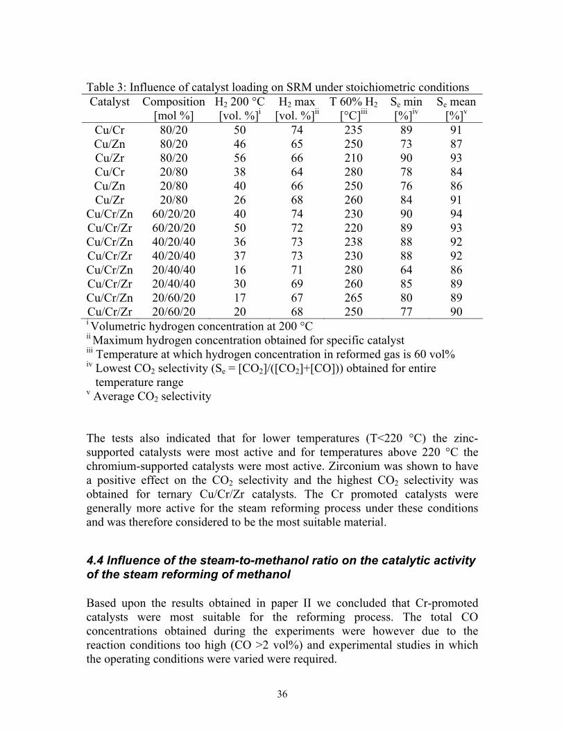
Table 3: Influence of catalyst loading on SRM under stoichiometric conditions Catalyst Composition
[mol %] H2 200 °C
[vol. %]i H2 max
[vol. %]ii T 60% H2
[°C]iii Se min [%]iv
Se mean [%]v
Cu/Cr 80/20 50 74 235 89 91 Cu/Zn 80/20 46 65 250 73 87 Cu/Zr 80/20 56 66 210 90 93 Cu/Cr 20/80 38 64 280 78 84 Cu/Zn 20/80 40 66 250 76 86 Cu/Zr 20/80 26 68 260 84 91
Cu/Cr/Zn 60/20/20 40 74 230 90 94 Cu/Cr/Zr 60/20/20 50 72 220 89 93 Cu/Cr/Zn 40/20/40 36 73 238 88 92 Cu/Cr/Zr 40/20/40 37 73 230 88 92 Cu/Cr/Zn 20/40/40 16 71 280 64 86 Cu/Cr/Zr 20/40/40 30 69 260 85 89 Cu/Cr/Zn 20/60/20 17 67 265 80 89 Cu/Cr/Zr 20/60/20 20 68 250 77 90 i Volumetric hydrogen concentration at 200 °C ii Maximum hydrogen concentration obtained for specific catalyst iii Temperature at which hydrogen concentration in reformed gas is 60 vol% iv Lowest CO2 selectivity (Se = [CO2]/([CO2]+[CO])) obtained for entire temperature range v Average CO2 selectivity The tests also indicated that for lower temperatures (T<220 °C) the zinc-supported catalysts were most active and for temperatures above 220 °C the chromium-supported catalysts were most active. Zirconium was shown to have a positive effect on the CO2 selectivity and the highest CO2 selectivity was obtained for ternary Cu/Cr/Zr catalysts. The Cr promoted catalysts were generally more active for the steam reforming process under these conditions and was therefore considered to be the most suitable material.
4.4 Influence of the steam-to-methanol ratio on the catalytic activity of the steam reforming of methanol Based upon the results obtained in paper II we concluded that Cr-promoted catalysts were most suitable for the reforming process. The total CO concentrations obtained during the experiments were however due to the reaction conditions too high (CO >2 vol%) and experimental studies in which the operating conditions were varied were required.

37
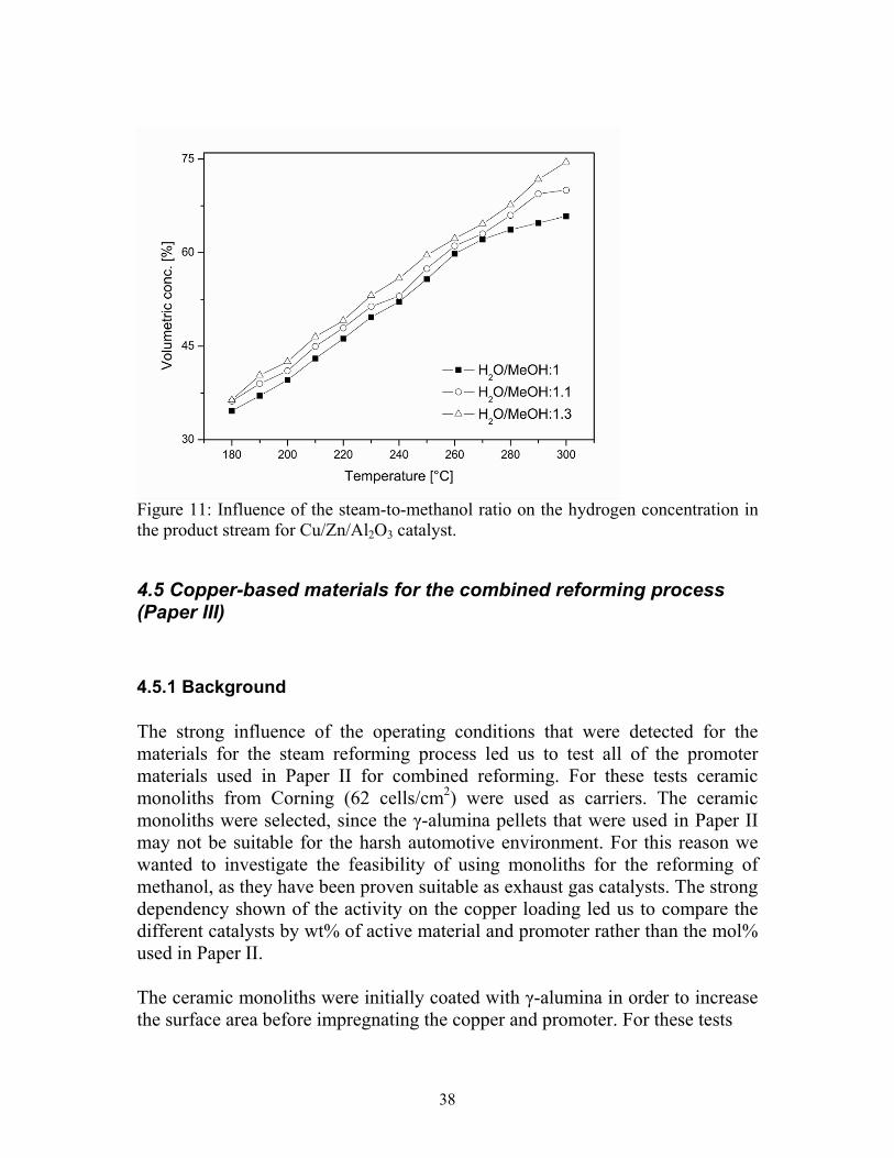
Figure 10: Influence of the steam-to-methanol ratio on the hydrogen concentration in the product stream for Cu/Cr/Al2O3 catalyst. Cu/Cr/Al2O3 catalysts were therefore prepared and tested for reforming under various steam-to-methanol ratios. The results (see Figure 10) showed that the activity severely decreased with increasing steam-to-methanol ratio. Furthermore the CO concentrations did not significantly decrease at the same time. We then therefore decided to test various Cu/Zn/Al2O3 and Cu/Zr/Al2O3 catalysts and discovered that the activity of the Zn-based catalysts was significantly increased as a result of increasing the steam-to-methanol ratio (see Figure 11) while producing notably lower CO concentrations (CO <1 %). The optimal steam-to-methanol ratio for the steam reforming process was found to be at approximately 1.3-1.4:1. These new results prompted us to switch to Cu/Zn/Al2O3 as the main catalytic material for the steam reforming process. The results also showed that the activity of the Zr-based catalysts decreased when increasing the steam-to-methanol ratio (slightly lower than for Cr-promoted), however, the CO concentrations were far the lowest for all of the materials tested.
38
Figure 11: Influence of the steam-to-methanol ratio on the hydrogen concentration in the product stream for Cu/Zn/Al2O3 catalyst.
4.5 Copper-based materials for the combined reforming process (Paper III)
4.5.1 Background The strong influence of the operating conditions that were detected for the materials for the steam reforming process led us to test all of the promoter materials used in Paper II for combined reforming. For these tests ceramic monoliths from Corning (62 cells/cm2) were used as carriers. The ceramic monoliths were selected, since the γ-alumina pellets that were used in Paper II may not be suitable for the harsh automotive environment. For this reason we wanted to investigate the feasibility of using monoliths for the reforming of methanol, as they have been proven suitable as exhaust gas catalysts. The strong dependency shown of the activity on the copper loading led us to compare the different catalysts by wt% of active material and promoter rather than the mol% used in Paper II. The ceramic monoliths were initially coated with γ-alumina in order to increase the surface area before impregnating the copper and promoter. For these tests

39
Table 4: Catalyst composition Catalyst Composition
[wt%] Active material
[wt%] CuZn 40:60 10.2 CuCr 40:60 10.1 CuZr 40:60 10.3
three different catalysts with the same total metal loading were prepared (see Table 4). The catalysts were evaluated for three operating conditions: Steam reforming (30 % excess steam), combined reforming at near auto-thermal operating conditions and combined reforming under slightly exothermic conditions. For a detailed description of the operating conditions and catalyst preparations please refer to Paper III.
4.5.2 Influence of the promoter material on the combined methanol reforming process The combined reforming process was highly efficient for all of the promoters used in this investigation. The CO concentration was however slightly elevated when running the process under exothermic conditions compared to steam reforming. The steam reforming process delivered lower H2 concentrations for the monolithic carriers compared to the pellet based catalysts, due to bad heat transfer between the channels in the monolith. This was not a problem for the combined reforming process as heat was generated at the entrance of the monolith channels. This problem was resolved in the study described in Paper IV by increasing the temperature of the reactants. The results from the experiments is shown in Table 5 below, and it can be seen that the activity for the catalysts was similar for the combined reforming process while the highest activity for the steam reforming process was obtained for the Zn-promoted catalyst. The Cr-promoted catalysts however generated significantly higher CO concentrations for all of the process alternatives. The high CO concentration makes Cr unsuitable for promoting copper-based catalysts for methanol reforming for fuel cell based applications. The Zr-promoted catalysts had the highest CO2 selectivity and may be suitable as part of a low temperature WGS reactor.

40
Table 5: Comparison of hydrogen generation processes Catalyst Process H2
210°C [vol%]i
H2 max
[vol%]ii
T 60% H2
[°C]iii
Se min[%]iv
Se mean [%]v
CO max
[vol%]vi
Cu/Zn SR 3.6 64 280 97 98 0.77 Cu/Cr SR 2.3 50 - 78 90 1.1 Cu/Zr SR 2.7 52 - 98 100 0.27 Cu/Zn CR1 8.3 73 230 94 97 1.1 Cu/Cr CR1 55 74 220 83 90 2.5 Cu/Zr CR1 2.1 72 252 86 95 0.84 Cu/Zn CR2 11 72 220 90 95 1.8 Cu/Cr CR2 54 72 215 90 78 1.8 Cu/Zr CR2 2.3 67 230 98 99 0.51
i Volumetric hydrogen concentration at 210 °C ii Maximum hydrogen concentration obtained for specific catalyst iii Temperature at which hydrogen concentration in reformed gas is 60 vol% iv Lowest CO2 selectivity (Se = [CO2]/([CO2]+[CO])) obtained for entire temperature range v Average CO2 selectivity vi Maximum CO concentration in product stream The results from this study suggests that Zn-promoted catalysts are most suitable for fuel cell applications for both steam reforming and combined reforming as they generate product streams with both high hydrogen content and low CO concentration.
4.6 Zirconia-doped catalysts for the steam reforming process (Paper IV)
4.6.1 Background Since we were convinced that the heat transfer limitations in the ceramic monoliths inhibited the performance of the catalysts we decided to preheat the reactants to the reactor temperature. While Zr-based catalysts were shown to have a lower activity than Zn-based catalysts they also, however, generated lower CO concentrations. We therefore wanted to investigate whether it was possible to increase the CO2 selectivity of Zn-based catalysts by doping them with Zr.
41
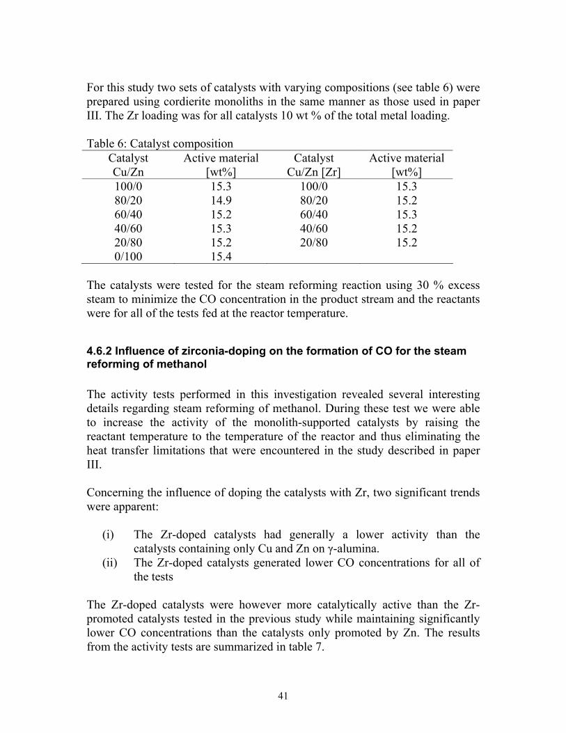
For this study two sets of catalysts with varying compositions (see table 6) were prepared using cordierite monoliths in the same manner as those used in paper III. The Zr loading was for all catalysts 10 wt % of the total metal loading. Table 6: Catalyst composition
Catalyst Cu/Zn
Active material [wt%]
Catalyst Cu/Zn [Zr]
Active material [wt%]
100/0 15.3 100/0 15.3 80/20 14.9 80/20 15.2 60/40 15.2 60/40 15.3 40/60 15.3 40/60 15.2 20/80 15.2 20/80 15.2 0/100 15.4
The catalysts were tested for the steam reforming reaction using 30 % excess steam to minimize the CO concentration in the product stream and the reactants were for all of the tests fed at the reactor temperature.
4.6.2 Influence of zirconia-doping on the formation of CO for the steam reforming of methanol The activity tests performed in this investigation revealed several interesting details regarding steam reforming of methanol. During these test we were able to increase the activity of the monolith-supported catalysts by raising the reactant temperature to the temperature of the reactor and thus eliminating the heat transfer limitations that were encountered in the study described in paper III. Concerning the influence of doping the catalysts with Zr, two significant trends were apparent:
(i) The Zr-doped catalysts had generally a lower activity than the catalysts containing only Cu and Zn on γ-alumina.
(ii) The Zr-doped catalysts generated lower CO concentrations for all of the tests
The Zr-doped catalysts were however more catalytically active than the Zr-promoted catalysts tested in the previous study while maintaining significantly lower CO concentrations than the catalysts only promoted by Zn. The results from the activity tests are summarized in table 7.

42
Table 7: Effect of zirconium doping Catalyst H2 210°C
[vol%]i H2 max [vol%]ii
T 60% H2 [°C]iii
Se min [%]iv
Se mean [%]v
CO max [vol%]vi
Cu100 58 68 225 97 98 0,69 Cu100 [Zr] 44 59 - 99 100 0,12 Cu80/Zn20 52 62 269 96 97 0,85 Cu80/Zn20 [Zr] 47 61 285 99 100 0,21 Cu60/Zn40 64 75 195 96 97 0,96 Cu60/Zn40 [Zr] 43 60 - 98 99 0,43 Cu40/Zn60 51 71 238 96 97 1 Cu40/Zn60 [Zr] 37 55 - 97 98 0,65 Cu20/Zn80 1,8 63 279 69 80 1,2 Cu20/Zn80 [Zr] 1,4 50 - 95 98 0,85 i Volumetric hydrogen concentration at 210 °C ii Maximum hydrogen concentration obtained for specific catalyst iii Temperature at which hydrogen concentration in reformed gas is 60 vol% iv Lowest CO2 selectivity (Se = [CO2]/([CO2]+[CO])) obtained for entire temperature range v Average CO2 selectivity vi Maximum CO concentration in product stream
4.7 Characterization of copper-based catalysts for methanol reforming (Paper V)
4.7.1 Background The results from the activity tests indicate that both the copper loading and promoter material have a strong influence on the activity and selectivity. In order to develop an understanding of these results we decided to perform a study aimed at understanding both the bulk and surface properties of the copper-based catalysts. For these tests we used spherical γ-alumina pellets (d=2.5 mm) from SASOL Germany. The catalysts were prepared using the wet-impregnation method and the total loading was increased to 15 wt % of the γ-alumina pellets for all of the catalysts used. In the previous experiments we loaded the catalysts with only 10-wt % of the γ-alumina. This change was implemented in order to increase the activity of the catalysts. For the test three sets of catalysts were prepared (see table 8) each with different promoter.
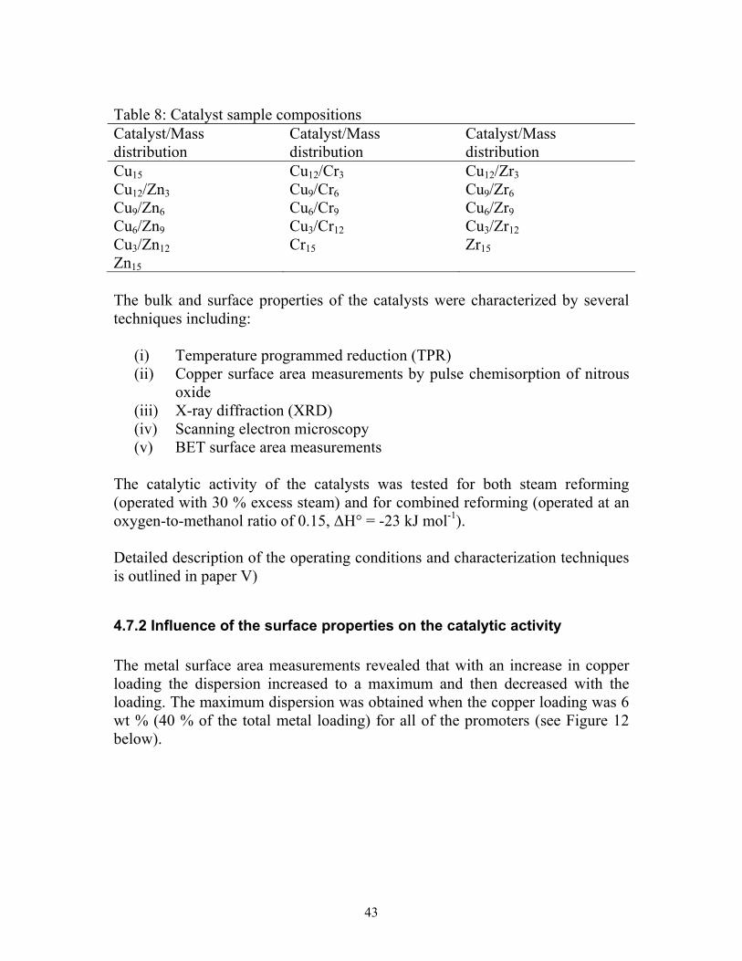
43
Table 8: Catalyst sample compositions Catalyst/Mass distribution
Catalyst/Mass distribution
Catalyst/Mass distribution
Cu15 Cu12/Cr3 Cu12/Zr3 Cu12/Zn3 Cu9/Cr6 Cu9/Zr6 Cu9/Zn6 Cu6/Cr9 Cu6/Zr9 Cu6/Zn9 Cu3/Cr12 Cu3/Zr12 Cu3/Zn12 Cr15 Zr15 Zn15 The bulk and surface properties of the catalysts were characterized by several techniques including:
(i) Temperature programmed reduction (TPR) (ii) Copper surface area measurements by pulse chemisorption of nitrous
oxide (iii) X-ray diffraction (XRD) (iv) Scanning electron microscopy (v) BET surface area measurements
The catalytic activity of the catalysts was tested for both steam reforming (operated with 30 % excess steam) and for combined reforming (operated at an oxygen-to-methanol ratio of 0.15, ∆H° = -23 kJ mol-1). Detailed description of the operating conditions and characterization techniques is outlined in paper V)
4.7.2 Influence of the surface properties on the catalytic activity The metal surface area measurements revealed that with an increase in copper loading the dispersion increased to a maximum and then decreased with the loading. The maximum dispersion was obtained when the copper loading was 6 wt % (40 % of the total metal loading) for all of the promoters (see Figure 12 below).
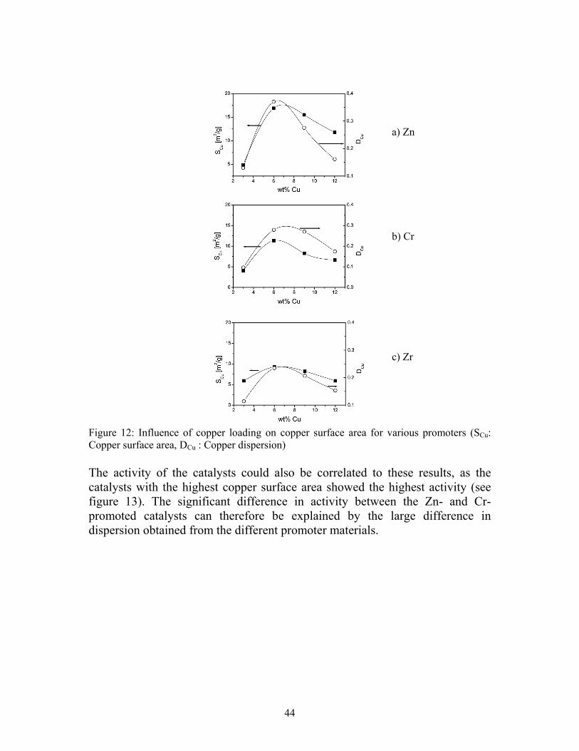
44
Figure 12: Influence of copper loading on copper surface area for various promoters (SCu: Copper surface area, DCu : Copper dispersion) The activity of the catalysts could also be correlated to these results, as the catalysts with the highest copper surface area showed the highest activity (see figure 13). The significant difference in activity between the Zn- and Cr-promoted catalysts can therefore be explained by the large difference in dispersion obtained from the different promoter materials.
a) Zn
b) Cr
c) Zr
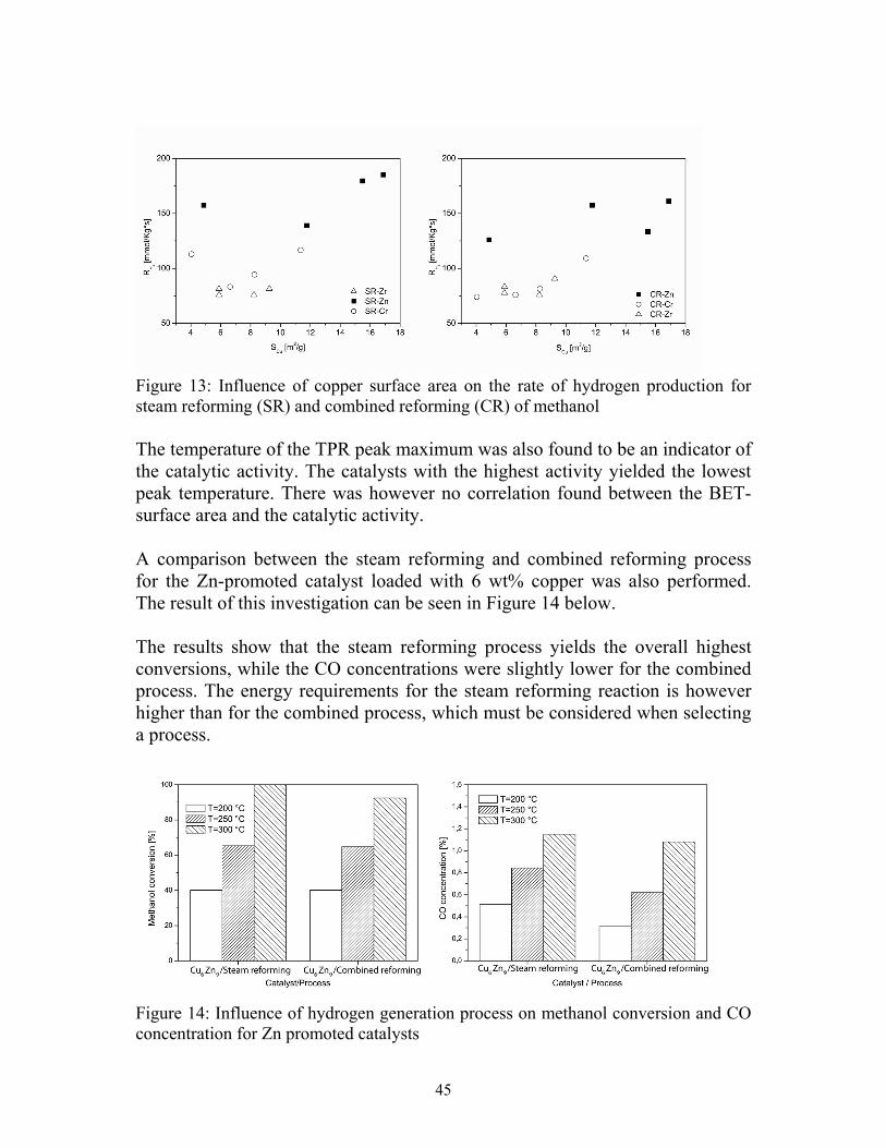
45
Figure 13: Influence of copper surface area on the rate of hydrogen production for steam reforming (SR) and combined reforming (CR) of methanol The temperature of the TPR peak maximum was also found to be an indicator of the catalytic activity. The catalysts with the highest activity yielded the lowest peak temperature. There was however no correlation found between the BET-surface area and the catalytic activity. A comparison between the steam reforming and combined reforming process for the Zn-promoted catalyst loaded with 6 wt% copper was also performed. The result of this investigation can be seen in Figure 14 below. The results show that the steam reforming process yields the overall highest conversions, while the CO concentrations were slightly lower for the combined process. The energy requirements for the steam reforming reaction is however higher than for the combined process, which must be considered when selecting a process.
Figure 14: Influence of hydrogen generation process on methanol conversion and CO concentration for Zn promoted catalysts

46
The study in Paper V shows that the activity and selectivity is dependent on several factors including: the copper loading, the copper dispersion as well as the promoter material.
4.8 Summary The studies which have been performed in papers II-V clearly show that copper-based materials can be successfully used for catalytic reforming of methanol. The tests also indicate that the choice of promoter and copper loading has a notable effect on both catalytic activity and selectivity. Catalysts promoted by zinc were most active and yielded a high CO2 selectivity. The CO2 selectivity of Zn-promoted catalysts could be improved by doping the catalysts with Zr, however, the doping lowers the CO concentrations at the expense of the catalytic activity.

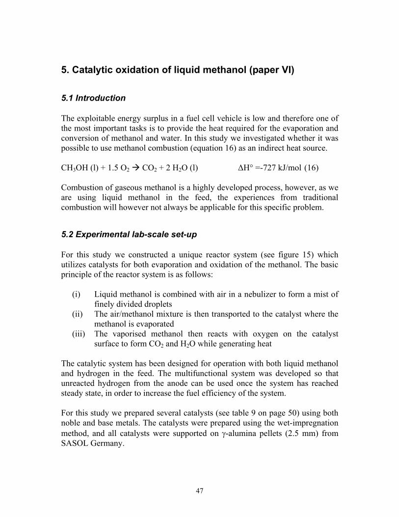
47
5. Catalytic oxidation of liquid methanol (paper VI)
5.1 Introduction The exploitable energy surplus in a fuel cell vehicle is low and therefore one of the most important tasks is to provide the heat required for the evaporation and conversion of methanol and water. In this study we investigated whether it was possible to use methanol combustion (equation 16) as an indirect heat source. CH3OH (l) + 1.5 O2 CO2 + 2 H2O (l) ∆H° =-727 kJ/mol (16) Combustion of gaseous methanol is a highly developed process, however, as we are using liquid methanol in the feed, the experiences from traditional combustion will however not always be applicable for this specific problem.
5.2 Experimental lab-scale set-up For this study we constructed a unique reactor system (see figure 15) which utilizes catalysts for both evaporation and oxidation of the methanol. The basic principle of the reactor system is as follows:
(i) Liquid methanol is combined with air in a nebulizer to form a mist of finely divided droplets
(ii) The air/methanol mixture is then transported to the catalyst where the methanol is evaporated
(iii) The vaporised methanol then reacts with oxygen on the catalyst surface to form CO2 and H2O while generating heat
The catalytic system has been designed for operation with both liquid methanol and hydrogen in the feed. The multifunctional system was developed so that unreacted hydrogen from the anode can be used once the system has reached steady state, in order to increase the fuel efficiency of the system. For this study we prepared several catalysts (see table 9 on page 50) using both noble and base metals. The catalysts were prepared using the wet-impregnation method, and all catalysts were supported on γ-alumina pellets (2.5 mm) from SASOL Germany.
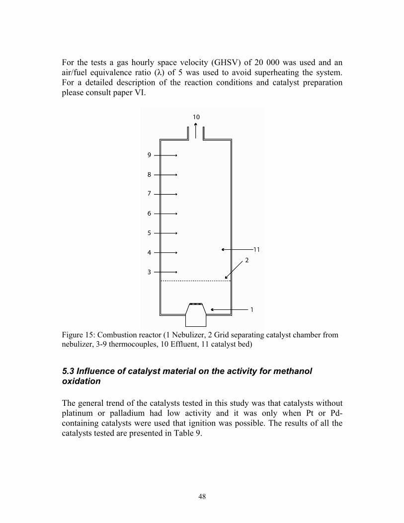
48
For the tests a gas hourly space velocity (GHSV) of 20 000 was used and an air/fuel equivalence ratio (λ) of 5 was used to avoid superheating the system. For a detailed description of the reaction conditions and catalyst preparation please consult paper VI.
Figure 15: Combustion reactor (1 Nebulizer, 2 Grid separating catalyst chamber from nebulizer, 3-9 thermocouples, 10 Effluent, 11 catalyst bed)
5.3 Influence of catalyst material on the activity for methanol oxidation The general trend of the catalysts tested in this study was that catalysts without platinum or palladium had low activity and it was only when Pt or Pd-containing catalysts were used that ignition was possible. The results of all the catalysts tested are presented in Table 9.

49
The Pd-based catalysts, however, had to be reduced to Pd from PdO in order for ignition to occur, and they were easily oxidised back to PdO. We therefore decided to abandon Pd in favour of Pt for the oxidation reaction. The Pt content was shown to have a great influence on the time-on-stream to ignition as well as the temperature distribution in the reactor. The risk for hot-spot formation was also shown to increase with the Pt loading (see figure 16). The formation of hot-spots increases the risk for thermal deactivation and should therefore be avoided. Further tests showed that it was possible to replace 75 % of the catalyst bed with a Mn-based catalyst while still maintaining complete conversion. The temperature distribution was also more even for the system with the mixed catalysts.
Figure 16: Influence of Pt loading on bed temperature

50
Tabl
e 9:
Act
ivity
test
s C
atal
yst
Cry
stal
pha
se1
Max
imum
met
hano
l co
nver
sion
[%]
Tim
e on
stre
am to
max
con
vers
ion
[s
] Pt
3 Pt
10
0 80
Pt
2 Pt
10
0 10
0 Pt
1 Pt
10
0 16
0 Pt
0.5
Pt
99
180
Pt0.
4 Pt
99
20
0 Pt
0.3
Pt
98
220
Pt0.
2 Pt
96
24
0 Pt
0.1
Pt
96
260
Pd3
PdO
22
30
02
Pd2
PdO
12
34
02
Pd1
PdO
5
3602
Pd3
Pd
95
180
Pd2
Pd
92
220
Pd1
Pd
89
240
Ag 1
5 A
gAlO
2 11
12
02
Ag 1
0 A
gAlO
2 12
10
02
Ag 1
0Pt 0.
5 A
gAlO
2, Pt
98
18
0 A
g 10P
t 0.3
AgA
lO2,
Pt
89
200
Ag 1
0Pt 0.
1 A
gAlO
2, Pt
72
22
0 C
o 15
Co 3
O4
21
2002
Co 1
0 C
o 3O
4 18
18
02
Co 1
0Pt 0.
5 C
o 3O
4, Pt
97
24
0 C
o 10P
t 0.3
Co 3
O4,
Pt
92
260

51
Co 1
0Pt 0.
1 C
o 3O
4, Pt
86
22
0 La
15
La2O
3 19
22
02
La10
La
2O3
16
2002
La10
Pt0.
5 La
2O3,
Pt
98
180
La10
Pt0.
3 La
2O3,
Pt
94
200
La10
Pt0.
1 La
2O3,
Pt
90
220
Mn 1
5 M
n 2O
3 27
26
02
Mn 1
0 M
n 2O
3 23
28
02
Mn 1
0Pt 0.
5 M
n 2O
3, Pt
10
0 12
0 M
n 10P
t 0.3
Mn 2
O3,
Pt
100
140
Mn 1
0Pt 0.
1 M
n 2O
3, Pt
10
0 16
0 Sr
15
SrO
9
1602
Sr10
Sr
O
10
1802
Sr10
Pt0.
5 Sr
O, P
t 97
20
0 Sr
10Pt
0.3
SrO
, Pt
91
220
Sr10
Pt0.
1 Sr
O, P
t 78
22
0 1 A
naly
zed
by X
-ray
diff
ract
ion
befo
re a
ctiv
ity te
stin
g 2 Ti
me
to e
xtin
ctio
n

52
5.4 Summary The results presented in this paper show that it is possible to catalytically combust liquid methanol at room temperature by using a nebulizer to disperse methanol and air over the catalyst bed. The results also showed that it is possible to use base-metal catalysts and that Pt is only required for the initial ignition of the system. The success of this study signified that it is possible to design an automotive reforming system which utilizes the combustion of liquid methanol as a source of heat for the reformer, thus eliminating the need for electric heating of the reactor. The reforming system will consequently be smaller as the required battery power is lowered.

53
6. Development and evaluation of a catalytic reforming system (Paper VII)
6.1 Introduction In Paper VI we successfully demonstrated that it was possible to catalytically ignite liquid methanol at room temperature. Based on this result it was decided that a compact reforming system, which utilized indirect heat exchange with combusted methanol, was to be developed. This is in contrast to traditional reactor systems where the reactants are preheated and the reactor temperature is controlled by a furnace. The objective of this current study was to develop and construct a self-sustainable compact methanol fuel processor for serving a 5 kWe PEFC. When determining the required hydrogen flow rates, calculations were made with the heating value of hydrogen while assuming that the efficiency of the fuel cell is 50 %. The required hydrogen flow per kWe was then found to be approximately 1000 Ndm3/h. Efforts were also made to optimise the fuel processor with respect to start-up time and CO2 selectivity.
6.2 Experimental set-up For this study we developed catalysts for the oxidation and reforming reaction based upon the results of Paper VI and Papers II-V, respectively. The reforming catalysts manufactured were copper-based and the oxidation catalyst was composed of a Pt/MnO2 mixture. The catalysts were all supported on γ-alumina pellets (2.5 mm) from SASOL Germany and prepared using the wet-impregnation method. For a more detailed description of the preparation parameters please refer to Paper VII. The catalytic reforming system constructed for this study (See Figure 17) consists of four separate modules: (i) catalytic combustor, (ii) vaporizer, (iii) reformer and (iv) shift reactor. The basic principles of the reforming system are as follows:
(i) Initially liquid methanol and air is fed to the catalytic combustor, which utilizes the catalyst for both evaporation and oxidation
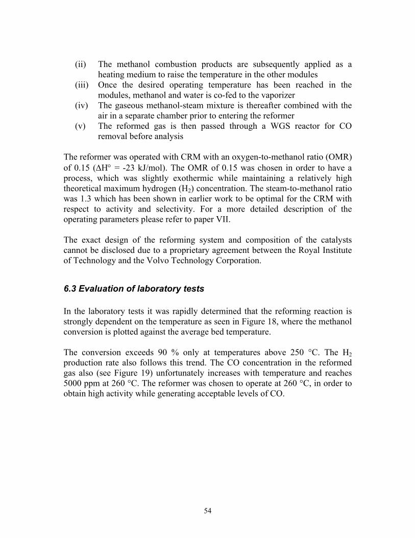
54
(ii) The methanol combustion products are subsequently applied as a heating medium to raise the temperature in the other modules
(iii) Once the desired operating temperature has been reached in the modules, methanol and water is co-fed to the vaporizer
(iv) The gaseous methanol-steam mixture is thereafter combined with the air in a separate chamber prior to entering the reformer
(v) The reformed gas is then passed through a WGS reactor for CO removal before analysis
The reformer was operated with CRM with an oxygen-to-methanol ratio (OMR) of 0.15 (∆H° = -23 kJ/mol). The OMR of 0.15 was chosen in order to have a process, which was slightly exothermic while maintaining a relatively high theoretical maximum hydrogen (H2) concentration. The steam-to-methanol ratio was 1.3 which has been shown in earlier work to be optimal for the CRM with respect to activity and selectivity. For a more detailed description of the operating parameters please refer to paper VII. The exact design of the reforming system and composition of the catalysts cannot be disclosed due to a proprietary agreement between the Royal Institute of Technology and the Volvo Technology Corporation.
6.3 Evaluation of laboratory tests In the laboratory tests it was rapidly determined that the reforming reaction is strongly dependent on the temperature as seen in Figure 18, where the methanol conversion is plotted against the average bed temperature. The conversion exceeds 90 % only at temperatures above 250 °C. The H2 production rate also follows this trend. The CO concentration in the reformed gas also (see Figure 19) unfortunately increases with temperature and reaches 5000 ppm at 260 °C. The reformer was chosen to operate at 260 °C, in order to obtain high activity while generating acceptable levels of CO.

55
Figu
re 1
7: T
he c
atal
ytic
refo
rmin
g sy
stem

56
Figure 18: Influence of temperature on methanol conversion
Figure 19: Influence of temperature on CO concentration
The ability to construct an automotive reformer with a low start-up time is a decisive factor for success. The start-up time was found to be dependent on the oxygen-to-methanol ratio in the reformer (see Figure 20).
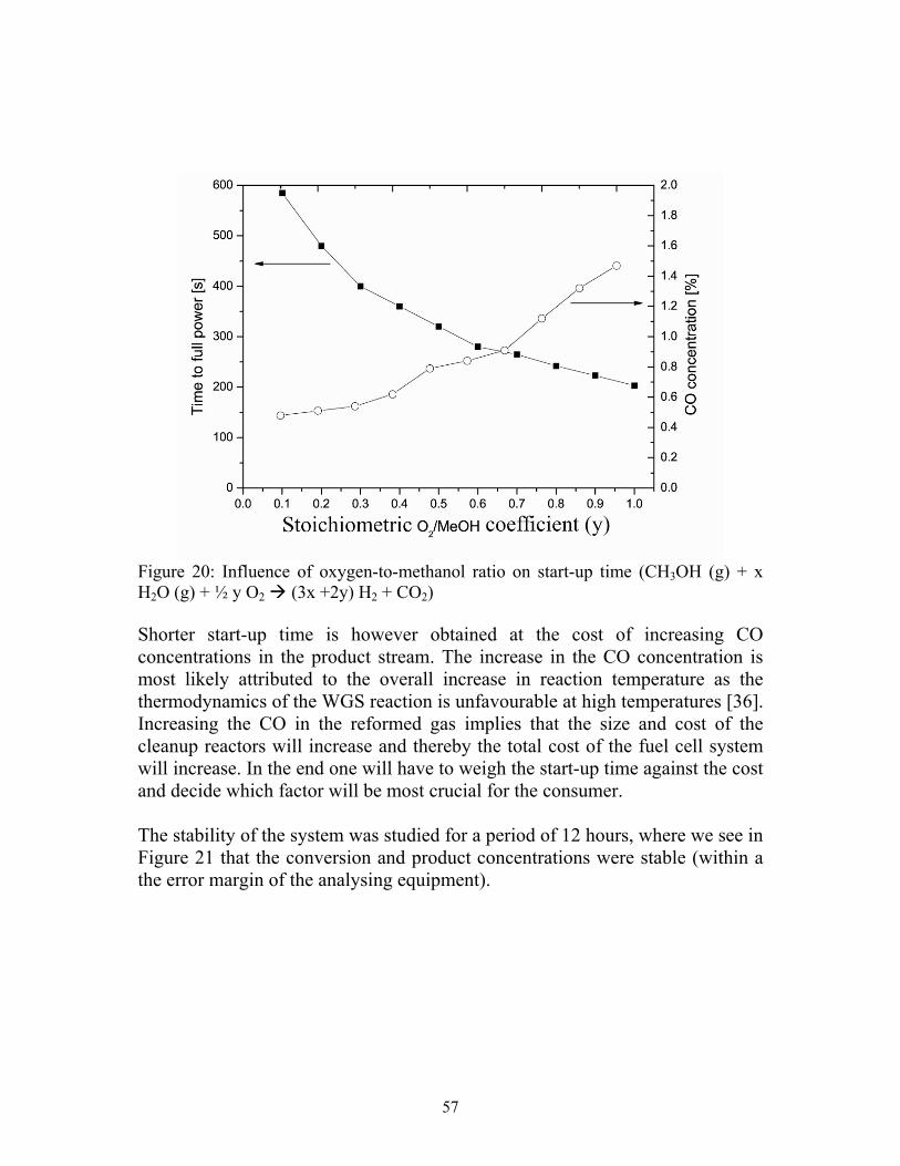
57
Figure 20: Influence of oxygen-to-methanol ratio on start-up time (CH3OH (g) + x H2O (g) + ½ y O2 (3x +2y) H2 + CO2) Shorter start-up time is however obtained at the cost of increasing CO concentrations in the product stream. The increase in the CO concentration is most likely attributed to the overall increase in reaction temperature as the thermodynamics of the WGS reaction is unfavourable at high temperatures [36]. Increasing the CO in the reformed gas implies that the size and cost of the cleanup reactors will increase and thereby the total cost of the fuel cell system will increase. In the end one will have to weigh the start-up time against the cost and decide which factor will be most crucial for the consumer. The stability of the system was studied for a period of 12 hours, where we see in Figure 21 that the conversion and product concentrations were stable (within a the error margin of the analysing equipment).

58
Figure 21: Stability test
6.4 Industrial evaluation and optimisation of reformer prototype The reformer was also tested and evaluated together with staff at the Volvo Technology Corporation in Gothenburg. During these tests we were able to increase the methanol conversion by increasing the oxygen-to-methanol ratio (see Figure 22).

59
Figure 22: Influence of oxygen-to-methanol ratio on the methanol conversion The CO concentration was also shown to increase with the increasing conversion, however we were able to maintain CO concentrations below 1 % while operating the reformer at maximum capacity. The start-up time of the reformer was also lowered to 2.3 minutes, by varying the OMR during start-up. However, this resulted in CO concentrations between 1.2 and 1.3 %. The equipment was not insulated during the experiments. The product gas was measured using a continuous detection system, consisting of a TCD detector for H2 and parallel continuous IR-detectors for CO and CO2, from BOO Instruments.
6.5 Summary The results from this study shows that it possible to construct a self-sustainable reformer operated without electrical heating. The CO concentrations obtained during the experiments calls for implementation of a preferential oxidizer prior to the fuel cell. The start-up times are currently not acceptable for automotive applications, however, the start-up times can be reduced by increasing the heat transfer characteristics of the system.

60
The system showed stability over time as well as over repeated start-up experiments both before and after 12 hour studies. The start-up time was also not notably affected by the exposure of the catalyst to the reactants for 12 hours.

61
7. Conclusions Catalytic hydrogen generation from methanol for fuel cell applications has received significant attention during the last two decades. The rapid development of novel catalytic materials during the last decades show a great potential for methanol reforming as a source for hydrogen production for automotive fuel cell applications. There is however still much room for improvement with respect to both the reactor design and the catalytic performance. The main conclusion of this work is that zinc-promoted copper-based catalysts are superior for methanol reforming for fuel cell applications with respect to activity and selectivity. It has also been shown that the reaction conditions have a significant impact on the catalytic performance. When studying the methanol reforming reaction, it was found that the water-to-methanol ratio had a strong influence on both the activity as well as on the product composition. The optimum reaction condition was found to be when operating the reformer with 30 % excess steam. The oxygen-to-methanol ratio was also found to affect the performance of the reformer, especially the start-up time and carbon monoxide concentration. It has also been shown that catalytic oxidation of liquid methanol can be utilized for heating the reformer during start-up. The catalytic material was shown to be crucial and platinum was the only material with sufficient activity. The utilization of various catalyst characterization techniques have provided means for understanding the dissimilar catalytic behaviour of different materials and compositions as well as providing a better understanding of the catalytic phenomena. When evaluating the reformer prototype developed in this project, it was clearly shown that the start-up time and product composition was strongly dependent on the feed composition. The start-up time could be reduced significantly by increasing the oxygen-to-methanol ratio, but this was however done at the expense of the carbon dioxide selectivity. This thesis has shown that it is possible to design a self-sustainable methanol reformer that generates carbon monoxide concentrations below 1 vol% in the product stream, while still being able to operate at 100 % methanol conversion.

62
There is however the need to improve the start-up times of the reformer before commercially introducing the technology to automotive fuel cell applications.

63
Acknowledgements First I would like to start by thanking my supervisor, Lars Pettersson, for his support and for always taking time to provide me with valuable feedback on my work. I would also like to thank Per Ekdunge at the Volvo Technology Corporation (VTEC) for providing valuable insight to the industrial viewpoint of automotive reforming throughout my project and for scrutinizing my thesis. I would like to thank the staff at VTEC for creative cooperation and for making me feel at home in their laboratory. Special appreciation to: Monika Råberg-Hellsing, Martin Berggren, Ricard Blanc, Lars Johansen, Lars Carlhammar and Göran Johansson. I would like to thank my colleagues and friends at Chemical Technology. Special thanks to Johan Agrell for great cooperation on papers I and III, Inga Groth for help with the SEM, XRD and BET analyses and to Otto von Krusenstierna for valuable discussions on the properties of the water-gas shift reaction. Special thanks are due to Krister Sjöström for reviewing my thesis. I would also like to thank P. Govind Menon for valuable insight on the various characterization techniques for copper catalysts and to Joakim Nordlund for interesting discussions on the properties of fuel cells. The financial support of the Swedish Energy Agency and Volvo Technology Corporation is gratefully acknowledged. Finally I would like to thank my good friends Egil Sjölander, Daniel Hagström and Roland Gustavsson for our traditional recreation every Thursday at Koppan.

64
Nomenclature Al2O3 Aluminium oxide (alumina) BET Brunauer-Emmet-Teller (surface area measurements) C2H5OH Ethanol CH3OH Methanol CH4 Methane CO Carbon monoxide CO2 Carbon dioxide Cr Chromium CR Combined Reforming CRM Combined Reforming of Methanol Cu Copper FCV Fuel Cell Vehicle FID Flame Ionisation Detector GHSV Gas Hourly Space Velocity H2 Hydrogen H2O Water i-C8H18 Iso-octane (2,2,4-trimethyl pentane) La Lanthanum Lambda (λ) Air/fuel equivalence ratio MFC Methanol Fuel Cell Mg Magnesium Mn Manganese MTBE Methyl tert-buthyl ether NH3 Ammonia Ni Nickel N2 Nitrogen NOx Nitrogen oxides O2 Oxygen OMR Oxygen-to-methanol ratio (mol O2/mol CH3OH) Pd Palladium PEFC Polymer Electrolyte Fuel Cell PO Partial Oxidation POM Partial Oxidation of Methanol

65
PROX Preferential oxidation Pt Platinum Rh Rhodium Se CO2 selectivity (Se=[CO2]/([CO2]+[CO])) SEM Scanning Electron Microscopy Si Silicon SOx Sulphur oxides SR Steam Reforming SRM Steam Reforming of Methanol SULEV Super Ultra Low Emission Vehicle TCD Thermal Conductivity Detector TPO Temperature Programmed Oxidation TPR Temperature Programmed Reduction WGS Water-Gas Shift reaction XRD X-ray diffraction Zn Zinc Zr Zirconium

66
References
[1] L. A. Waddell, Egyptian Civilization: Its Sumerian Origin, Real Chronology, Noontide Press; ASIN: 0317532014; 1988.
[2] The new Encyclopaedia Britannica, 15th ed, Encyclopaedia Britannica, London,
2002. [3] J.D. Scheell, Världens bilar i färg, Politiken forlag AS, Copenhagen, 1962. [4] A. Lewis, An Outline history of transportation from 1400 B.C. 1, Fisher Body
Craftsman's Guild, Detroit, 1934. [5] D. Burgess-Wise, The illustrated history of automobiles, Golden Press, Sydney,
1981. [6] D.A. Wick, Automobile History Day by Day, Hedemarken Collectibles, 1997. [7] G.S. May (Ed.), The Automobile Industry, 1896-1920 (Encyclopaedia of
American Business History, Biography), Facts on File Inc., 1990. [8] G.N. Georgano (Ed.), The Complete encyclopaedia of commercial vehicles,
Motorbooks International, Osceola, 1979. [9] P. Degobert, Automobiles and pollution, Society of Automotive Engineers,
Warrendale, PA, 1995. [10] J.B. Heywood, Internal Combustion Engine Fundamentals, McGraw-Hill, New
York, 1988. [11] R. Carson, Silent Spring, Mariner Books, 1994. [12] W. Grant, Autos, Smog, Pollution Control: The Politics of Air Quality
Management in California, Edward Elgar Publisher, 1996. [13] US Department of Energy, Green Power Fuel Cells, Washington DC, 1999. [14] California Fuel Cell Partnership, Driving for the future, California, 2001. [15] H. Davy, Nicholson’s Mag. 1 (1802) 144.

67
[16] W.R. Grove, Phil. Magazine, 14 (1839) 127. [17] S. Velu, K. Suzuki, M.P Kapoor, F. Ohashim, T. Osaki, Appl. Catal. A 213
(2001) 47. [18] T.J. Schmidt, H.A. Gasteiger, R.J. Behm, J. Electrochem. Soc. 146 (1999) 1296. [19] S.J. Lee, E.A. Mukerjee, J. McBreen, Electrochim. Acta 44 (1999) 3283. [20] Ahmed, M. Krumpelt, Int. J. Hydrogen Energy 26 (2001) 291. [21] J. Armor, Appl. Catal. A 176 (1999) 159. [22] L.F. Brown, Int. J. Hydrogen Energy 26 (2001) 381. [23] J. Larminie, A. Dicks, John Wiley & Sons , Chichester 2000. [24] D. Lide (Ed.),Handbook of Chemistry and Physics, 80th ed., CRC Press, Boca
Raton, 1999. [25] B. Emonts, J. Bøgild Hansen, H. Schmidt, T. Grube, B. Höhlein, R. Peters, A.
Tschauder, J. Power Sources 86 (2000) 228. [26] US Department of Energy, Fuel Cells for transportation: Annual progress report
98, Washington DC, 1998. [27] Kirk-Othmer, Encylopedia of Chemical Technology, Vol 16, John Wiley &
Sons , New York, 1995. [28] B. Elvers, S. Hawkins, G. Schulz (Ed.), Ullman’s Encyclopedia of Industrial
Chemistry, Vol. A16, VCH, Weinheim, 1990. [29] J.K. Paul (Ed.), Methanol technology, Application, Noyes Data publication,
Park Ridge, 1978. [30] J.A. Monick, Alcohols: Their chemistry and properties , Bernhold Book Corp,
1968. [31] R. Boyle, The Sceptical Chymist, 1661. [32] J.A. Moulijn, M. Makkee, A. Van Diepen, Chemical Process Technology, John
Wiley & Sons, Chichester, 2001.
68
[33] W. Haynes, American Chemical Industry-A history, Vol IV 1923-1929, Van
Nostrand, 1948. [34] K.C. Waugh, Catal. Today, 15 (1992), 51. [35] J.R. Rostrup-Nielsen, Steam reforming catalysts, Teknisk Forlag A/S,
Copenhagen, 1975. [36] L. Lloyd, D.E. Ridler, M.V. Twigg, in M.V. Twigg (Ed.), Catalyst Handbook,
Wolfe Publishing, London, 1989. [37] Methanol Institute, World Methanol plants (through December 2001),
Washington DC, 2002. [38] N.I. Sax, Dangerous Properties of Industrial Materials, Reinhold Publishing
Corporation, New York, 1963. [39] L.J. Pettersson, R. Westerholm, Int. J. Hydrogen Energy 26 (2001) 243. [40] L. Pettersson, K. Sjöström, Combust. Sci. Technol. 80 (1991) 265. [41] J.P. Breen, J.R.H. Ross, Catal. Today. 51 (1999) 521. [42] Peppley, J.C. Amphlett, L.M. Kearns, R.F. Mann, Appl. Catal. A 179 (1999) 21-
29 [43] F. Raimondi, K. Geissler, J. Wambach, A. Wokaun, Appl. Surf. Sci. 189 (2002)
59. [44] Y. Lwin, W. Ramli,W. Daud, A.B. Mohamad, Z. Yaakob, Int. J. Hydrogen
Energy 25 (2000) 47. [45] Y. Choi, H.G. Stenger, Appl. Catal B 38 (2002) 259 [46] S.R. Segal, K.B. Anderson, K.A. Carrado, C.L. Marshall, Appl. Catal. A 231
(2002) 215 [47] L. Cubeiro, J.L.G. Fierro, Appl. Catal. A 168 (1998) 307. [48] S. Velu, K. Suzuki, T. Osaki, Catal. Lett. 62 (1999) 159.

69
[49] J. Agrell, K. Hasselbo, K. Jansson, S.G. Järås, M. Boutonnet, Appl. Catal. A 211 (2001) 239.
[50] T. L. Reitz, S. Ahmed, M. Krumpelt, R. Kumar, H. H. Kung, J. Mol. Catal A
162 (2000) 275. [51] E.D. Schrum, T.L. Reitz, H.H. Kung, Stud. Surf. Sci. Catal. 139 (2001) 229. [52] T.L. Reitz, P.L. Lee, K.F. Czaplewski, J.C. Lang, K.E. Popp, H.H. Kung, J.
Catal 199 (2001) 193. [53] S. Velu, K. Suzuki, M. Okaziki, M.P. Kapoor, T. Osaki, F. Ohashi, J. Catal. 194
(2000) 373. [54] US Department of Energy, Transportation Fuel Cell Systems: 2000 Annual
progress report, Washington DC, 2000. [55] F.R. Kalhammer, P.R. Prokopius, V. Roan, G.E. Voecks, Status, Prospects of
Fuel Cells as Automobile Engines. A report of the Fuel Cell Advisory Panel. State of California Air Resources Board, Sacramento, California, USA, 1998.
[56] J. M. Zalc, D. G. Löffler, J. Power Sources 111 (2002) 58. [57] I. H. Son, M. Shamsuzzoha, A. M. Lane, J. Catal 210 (2002) 460. [58] S.H. Lee, J.Han, K.Y. Lee, J. Power Sources 109 (2002) 394. [59] B.A. Peppley, J.C. Amphlett, L.M. Kearns, R.F. Mann, Appl. Catal. A 179
(1999), 31. [60] S.P. Asprey, B.W. Wojciechowski , B.A. Peppley, Appl. Catal. A 179 (1999)
51. [61] C.J. Jiang, D.L. Trimm, M.S. Wainwright, N.W. Cant, Appl. Catal. A 97 (1993)
145. [62] E. Santacesaria, S. Carra, Appl. Catal. 5 (1983) 345. [63] K. Takahashi, N. Takezawa, H. Kobayashi, Appl. Catal. 2 (1982) 363. [64] H. Kobayashi, N. Takezawa, C. Minochi, J. Catal. 69 (1981) 487.

70
[65] G.-C. Shen, S.-i. Fujita, S. Matsumoto, N. Takezawa, J. Mol. Catal. A 124 (1997) 123.
[66] J.P. Breen, F.C. Meunier, J.R.H. Ross, Chem. Commun. 22 (1999) 2247. [67] C.J. Jiang, D.L. Trimm, M.S. Wainwright, N.W. Cant, Appl. Catal. A 93 (1993)
245. [68] J. C. Amphlett, K.A.M. Creber, J. M. Davis, R. F. Mann, B. A. Peppley , D. M.
Stokes, Int. J. Hydrogen Energy 19 (1994) 131. [69] K. Miyao, H. Onodera, N. Takezawa, React. Kinet. Catal. Lett. 53 (1994) 379. [70] N. Takezawa, Kobayashi, A. Hirose, M. Shimokawabe , K. Takahashi, Appl.
Catal. 4 (1982) 127. [71] N. Iwasa, S. Masuda, N. Ogawa , N. Takezawa, Appl. Catal. A 125 (1995) 145. [72] N. Takezawa , N. Iwasa, Catal. Today 36 (1997) 45. [73] N. Iwasa, S. Kudo, H. Takahashi, S. Masuda, N. Takezawa, Catal. Lett. 19
(1993) 211. [74] S. Renzi, R. Crawford, Corporate Environmental Strategy 7 (2000) 38. [75] M.L. Cubeiro, J.L.G. Fierro, J. Catal. 179 (1998) 150. [76] S. Velu, K.Suzuki, T. Osaki, Catal. Lett. 62 (1999) 159. [77] L. Alejo, R. Lago, M.A. Peña , J.L.G. Fierro, Appl. Catal. A 162 (1997) 281. [78] T.-J. Huang, S.-L. Chren, Appl. Catal. 40 (1988) 43. [79] M.A. Peña, J.P. Gomez , J.L.G. Fierro, Appl. Catal. A 144 (1996) 7. [80] J.L.G. Fierro, Stud. Surf. Sci. Catal. 130 (2000) 177. [81] T.-J. Huang, S.-W. Wang, Appl. Catal. 24 (1986) 287.