development of a precision system for image-guided needle ... · development of a precision system...
TRANSCRIPT

Maarten Menno Arnolli
- from scratch to clinic -
Development of a precision systemfor image-guided needle placement


Maarten Menno Arnolli
- from scratch to clinic -
Development of a precision systemfor image-guided needle placement

The research described in this dissertation has been conducted at DEMCON Ad-vanced Mechatronics [1] in collaboration with the University of Twente [2], andhas been funded by the following research programmes:
ITEA 2, 09039, Mediate – Patient-friendly medical intervention,
ITEA 3, 13031, Benefit – Better effectiveness and efficiency by measuring andmodelling of interventional therapy,
SNN, Ricibion – Robotic interventions using CT-images for biopsies of lungnodules.
Copyright c© 2017 by Maarten Arnolli, the Netherlands.
All rights reserved. This book or any portion thereof may not be reproduced orused in any manner whatsoever without the express written permission of thecopyright owner.
Printed by Ipskamp Printing, Enschede, the Netherlands.
ISBN: 978-90-365-4332-3
DOI: 10.3990/1.978903654332-3

DEVELOPMENT OF A PRECISION SYSTEMFOR IMAGE-GUIDED NEEDLE PLACEMENT
- FROM SCRATCH TO CLINIC -
DISSERTATION
to obtain
the degree of doctor at the University of Twente,
on the authority of rector magnificus
prof.dr. T.T.M. Palstra,
on account of the decision of the graduation committee,
to be publicly defended
on Wednesday 24 May, 2017 at 14:45
by
Maarten Menno Arnolli
born on 13 July, 1983
at Noordlaren, the Netherlands

This dissertation is approved by:
Prof.dr. I.A.M.J. Broeders (supervisor)
Prof.dr.ir. D.M. Brouwer (supervisor)
Dr.ir. M.C.J. Franken (co-supervisor)

Graduation committee
Chairman & Secretary: Prof.dr. P.M.G. ApersFaculty of Electrical Engineering, Mathematics and ComputerScience, University of Twente, the Netherlands
Supervisors: Prof.dr. I.A.M.J. BroedersMinimally Invasive Surgery & Robotics, MIRA Institute forBiomedical Technology & Technical Medicine, University ofTwente, the Netherlands
Prof.dr.ir. D.M. BrouwerPrecision Engineering, Science-based Engineering, University ofTwente, the Netherlands
Co-supervisor: Dr.ir. M.C.J. FrankenDEMCON Nymus3D, the Netherlands
Members: Prof.dr.ir. J.L. HerderMechanisms & Robotics Design, CTIT Institute for ICT Research inContext, University of Twente, the Netherlands
Prof.dr.ir. H. van der KooijBiomechatronics & Rehabilitation Technology, MIRA Institute forBiomedical Technology & Technical Medicine, University ofTwente, the Netherlands
Prof.dr. M.A.A.J. van den BoschInterventional Radiology, University Medical Center Utrecht, theNetherlands
Prof.dr.ir. J. DankelmanMedical Instruments & Bio-Inspired Technology, BioMechanicalEngineering, Delft University of Technology, the Netherlands
Referees: Dr. K.P. de JongHepato-Pancreato-Biliary Surgery & Liver Transplantation,University Medical Center Groningen, the Netherlands
Dr. M.J.A. JanninkBusiness Unit Medical Systems, DEMCON AdvancedMechatronics, the Netherlands
iii

Paranymphs: Ing. M. BuijzeMechanical & Industrial Design Engineering, DEMCON AdvancedMechatronics, the Netherlands
Ing. M.Ph. ArnolliBrother of the doctoral candidate
iv

To my parents, Ko & Ria.


Summary
Advances in medical technology enable an ongoing transition from invasive,open surgery to minimally invasive diagnostics and intervention. In the field ofoncology, percutaneous techniques have emerged in which biopsy and ablationof tumours are performed via a needle through the skin using image-guidance.X-ray CT-guided needle placement in the thorax and abdomen is convention-ally performed freehand. The performance of this method is user-dependent andmultiple iterations are generally required to achieve satisfactory placement. Tis-sue damage, patient X-ray exposure, procedure time and costs increase with eachplacement iteration. The objective of this research is the development of a pre-cision system for CT-guided percutaneous needle placement in the thorax andabdomen to improve upon the freehand method. It covers the entire strategic, ar-chitectural and detail design and realization of a complete system from first ideato prototype, its technical verification, its integration in the intervention suite andits pre-clinical validation, up to its first deployment in clinical practise.
The state of the art encompasses a wide variety of needle placement systems,from simple passive aids to fully automated robots. Despite the various attemp-ted strategies, widespread clinical adoption of any system is lacking. A novel,patent pending system has been designed with a focus on clinical acceptability,applicability and usability. It provides a needle guide aimed by a 2-DOFs auto-mated remote centre of motion (RCM) mechanism, connected to the CT table viaa passive 6-DOFs linkage. The linkage enables a physician to manually placethe RCM mechanism anywhere around the patient to coincide the RCM with thedesired skin entry point and push-button lock it. The relevant anatomy of the pa-tient and the system are CT scanned to acquire a 3D image, for automatic system-to-CT registration using incorporated fiducial markers, and for target specifica-tion and path approval in a graphical user interface. The needle guide is automat-ically aimed at the target, which is reached by a single manual needle insertion toindicated depth. Deceivingly simple in looks and usability, enabling the desiredfunctionality and performance under requirements on X-ray transparency, sizeand shape, demanded resorting to unconventional solutions using ceramic andcomposite precision parts, remote actuation via endless Dyneema cables, fibreoptical encoders, carbon nanotube electrical circuits and a pneumatic-hydrauliclocking system, all customized and confined in a compact design.
In a comparative phantom study involving two experienced physicians, theperformance of the system’s guided method was proven superior to the freehandmethod in every aspect: successful needle placement was consistently achievedin a single insertion, with lower geometric placement errors, fewer CT scans,lower radiation dose and shorter placement time. The output of this researchis a fully functional system, currently proving its merits in clinical practise.
vii

viii

Samenvatting
Vooruitgang in medische technologie maakt een steeds verdergaande verschui-ving mogelijk van invasieve, open chirurgie naar minimaal invasieve diagnos-tiek en interventie. Op het gebied van de oncologie hebben percutane techniekenhun intrede gedaan, waarbij biopsie en ablatie van tumoren worden uitgevoerdvia een naald door de huid met behulp van beeldgeleiding. Röntgen-CT-geleidenaaldplaatsing in de thorax en abdomen wordt conventioneel handmatig uitge-voerd. De prestatie van deze methode is persoonsafhankelijk en meerdere ite-raties zijn over het algemeen nodig om tot een toereikende plaatsing te komen.Met iedere iteratie nemen weefselschade, blootstelling van de patiënt aan rönt-genstraling, en de doorlooptijd en kosten van de procedure toe. Het doel van ditonderzoek is de ontwikkeling van een precisie systeem voor CT-geleide percu-tane naaldplaatsing in de thorax en abdomen ter verbetering van de handmatigemethode. Het beslaat het volledige strategisch, architectonisch en detail ontwerpen realisatie van een compleet systeem van eerste idee tot prototype, de techni-sche verificatie, de integratie in de interventiekamer en de preklinische validatie,tot aan de eerste inzet in de klinische praktijk.
De stand van de techniek omvat een grote variëteit aan bestaande naald-plaatsingssystemen, van simpele passieve hulpmiddelen tot volledig geautoma-tiseerde robots. Ondanks de verscheidenheid aan strategieën blijft brede klini-sche adoptie van een systeem uit. Een nieuw systeem waarop octrooi is aange-vraagd is ontworpen met een focus op klinische acceptatie, toepasbaarheid en ge-bruiksvriendelijkheid. Het biedt een naaldgeleiding die gericht wordt door een 2-DOFs geautomatiseerd remote-centre-of-motion (RCM) mechanisme, gekoppeldaan de CT tafel via een passieve 6-DOFs arm. De arm stelt de arts in staat hetRCM mechanisme overal rond de patiënt te plaatsen zodanig dat het RCM sa-menvalt met het gewenste entree punt op de huid, en het met één druk op deknop vast te zetten. De relevante anatomie van de patiënt en het systeem wordenCT gescand om een 3D beeld te verkrijgen, voor automatische systeem-naar-CTregistratie met behulp van ingebouwde referentiepunten, en voor specificatie vanhet doelwit en goedkeuring van het naaldpad in een grafische gebruikersomge-ving. De naaldgeleiding wordt automatisch gericht op het doelwit, welke bereiktwordt in een enkele handmatige insertie tot de aangegeven diepte. Hoewel hetuiterlijk en de bediening bedrieglijk simpel zijn, vereiste het mogelijk maken vande gewenste functionaliteit en prestatie onder de gestelde eisen aan röntgenstra-ling transparantie, grootte en vorm, een toevlucht tot onconventionele oplossin-gen, gebruikmakend van keramische en composiet precisiedelen, aandrijving opafstand via eindeloze Dyneema kabels, fiber-optische encoders, carbon-nanotubeelektrische circuits en een pneumatisch-hydraulisch klemsysteem, allemaal opmaat gemaakt en samengepakt in een compact ontwerp.
ix

In een vergelijkende fantoom studie met twee ervaren artsen is aangetoonddat de prestatie van de geleide methode van het systeem op ieder vlak superi-eur is aan de handmatige methode: succesvolle naaldplaatsing werd consistentin een enkele insertie bereikt, met lagere geometrische plaatsingsfouten, minderCT scans, lagere stralingsdosis en kortere plaatsingstijd. De uitkomst van dit on-derzoek is een volledig functioneel systeem, dat op dit moment zijn meerwaardeaantoont in de klinische praktijk.
x

Contents
Graduation committee iii
Summary vii
Samenvatting ix
1 Introduction 11.1 Background . . . . . . . . . . . . . . . . . . . . . . . . . . . . . . . . 11.2 Objective . . . . . . . . . . . . . . . . . . . . . . . . . . . . . . . . . . 51.3 Contributions & dissertation outline . . . . . . . . . . . . . . . . . . 51.4 Scientific output . . . . . . . . . . . . . . . . . . . . . . . . . . . . . . 7
2 An overview of systems for CT- and MRI-guided percutaneous needleplacement in the thorax and abdomen 92.1 Introduction . . . . . . . . . . . . . . . . . . . . . . . . . . . . . . . . 102.2 Materials & methods . . . . . . . . . . . . . . . . . . . . . . . . . . . 102.3 Results . . . . . . . . . . . . . . . . . . . . . . . . . . . . . . . . . . . 112.4 Discussion . . . . . . . . . . . . . . . . . . . . . . . . . . . . . . . . . 28
3 System for CT-guided needle placement in the thorax and abdomen - adesign for clinical acceptability, applicability and usability 393.1 Introduction . . . . . . . . . . . . . . . . . . . . . . . . . . . . . . . . 403.2 Materials & methods . . . . . . . . . . . . . . . . . . . . . . . . . . . 413.3 Results . . . . . . . . . . . . . . . . . . . . . . . . . . . . . . . . . . . 473.4 Discussion . . . . . . . . . . . . . . . . . . . . . . . . . . . . . . . . . 58
4 Deflection of needles for percutaneous procedures in the liver by axiallyguided insertion in ex vivo porcine liver tissue 614.1 Introduction . . . . . . . . . . . . . . . . . . . . . . . . . . . . . . . . 624.2 Material & methods . . . . . . . . . . . . . . . . . . . . . . . . . . . . 634.3 Results . . . . . . . . . . . . . . . . . . . . . . . . . . . . . . . . . . . 704.4 Discussion . . . . . . . . . . . . . . . . . . . . . . . . . . . . . . . . . 72
5 A precision system for CT-guided needle placement in the thorax andabdomen - design & performance analysis 755.1 Introduction . . . . . . . . . . . . . . . . . . . . . . . . . . . . . . . . 765.2 The registration system . . . . . . . . . . . . . . . . . . . . . . . . . . 785.3 The drive system . . . . . . . . . . . . . . . . . . . . . . . . . . . . . 845.4 The structural link . . . . . . . . . . . . . . . . . . . . . . . . . . . . . 89
5.5 The overall system . . . . . . . . . . . . . . . . . . . . . . . . . . . . 955.6 Discussion . . . . . . . . . . . . . . . . . . . . . . . . . . . . . . . . . 97
6 Validation of a system for CT-guided needle placement in the thorax andabdomen - a phantom study 1016.1 Introduction . . . . . . . . . . . . . . . . . . . . . . . . . . . . . . . . 1026.2 Materials & methods . . . . . . . . . . . . . . . . . . . . . . . . . . . 1026.3 Results . . . . . . . . . . . . . . . . . . . . . . . . . . . . . . . . . . . 1106.4 Discussion . . . . . . . . . . . . . . . . . . . . . . . . . . . . . . . . . 115
7 Conclusions & outlook 1197.1 Conclusions . . . . . . . . . . . . . . . . . . . . . . . . . . . . . . . . 1197.2 Outlook . . . . . . . . . . . . . . . . . . . . . . . . . . . . . . . . . . . 123
A Development history 131
References 169
Acknowledgements 191
About the author 201

CHAPTER 1
Introduction
1.1 Background
Advances in technology enable an ongoing transition from invasive, open sur-gery to minimally- or non-invasive diagnostics and intervention. This bringsbenefits such as less tissue damage, reduced pain, less scarring, lower risk ofcomplications, shorter or no hospital stays and faster recovery. Established tech-niques find access to internal sites via natural orifices (e.g. colonoscopy and bron-choscopy), blood vessels (angioscopy) or minor incisions in the abdomen (laparo-scopy) or thorax (thoracoscopy). In the field of oncology, image-guided percutaneoustechniques have emerged, in which target tissue is approached through the skinby a needle.
1.1.1 Percutaneous techniques in liver & lung cancer
Percutaneous techniques are frequently applied in the diagnostics and treatmentof liver and lung cancer. Percutaneous biopsy, the analysis of a tissue sampleharvested via a needle, has become a standard procedure in diagnostic patho-logy [3, 4]. The gold standard for treatment with curative intent of liver tumoursis surgical resection (hepatectomy) [5]. However, only 5 to 20% of patients are con-sidered amenable to resection [6, 7], because of limited hepatic reserve, a largenumber of tumours, a tumour’s proximity to the main vascular or biliary struc-tures and/or comorbidities. The gold standard for curative treatment of lungcancer is surgical resection of the involved lung lobe (pulmonary lobectomy), whichis shifting in approach from invasive via an incision in the chest (thoracotomy)to minimally invasive surgery by thoracoscopy [8]. Percutaneous local ablationtechniques provide a minimally invasive alternative for the treatment of tumoursin the liver [9–12] and lungs [13–18]. Examples are radio frequency ablation (RFA)and microwave ablation (MWA): destruction of tissue by radio or microwave in-duced heat, ethanol ablation: destruction by alcohol insertion, cryoablation: destruc-tion by freezing, and brachytherapy: destruction by ionizing radiation.
Epidemiological estimates from GLOBOCAN 2012 [19] emphasize the signi-ficance of the potential role for percutaneous techniques. Worldwide, 70 to 90%of primary liver cancer in adults is hepatocellular carcinoma (HCC) [20], causedby a viral infection with hepatitis B or C, or by cirrhosis, a disease which causeschronic liver damage. A worldwide incidence of 782.500 of primary liver can-cer and a mortality of 745.500 has been estimated, with highest rates in East
1

2 Chapter 1
(a) Siemens [35] Acuson NX3 US system.c© http://www.siemens.com/press.
(b) US image of the liver.c© http://www.siemens.com/press.
Figure 1.1: Ultrasonography.
and South-East Asia and Northern and Western Africa. Secondary liver cancerimplies liver tumours are metastatic, originating in a different organ or part ofthe body. Colorectal liver metastases (CRLM) develop in 50% of patients withcolorectal cancer [21], which has an estimated worldwide incidence of 1.400.000and mortality of 693.900. Lung cancer has the highest estimated worldwide in-cidence and mortality, at 1.824.700 and 1.589.900 respectively.
1.1.2 Image-guidance
Percutaneous procedures rely on image-guidance for pre-procedural planning,needle targeting, treatment effect monitoring, intra-procedural treatment modi-fication and post-procedural assessment of treatment response [22, 23], providedby techniques such as ultrasonography (US), radiography, and magnetic resonanceimaging (MRI).
US is based on tissue differences in echogenicity, the ability to bounce an echo.US is performed by decting echoes of ultrasonic waves emitted from a hand-held transducer on the skin (Fig. 1.1). It is a readily available real-time imagingmodality used for both percutaneous liver biopsy [24–26] and ablation [27–31].Intravenous administration of micro-bubbles is widely used in Europe and Asiato provide sufficient contrast enhancement of blood vessels [32], but has only re-cently received approval for the liver in the USA [33]. US is unsuited for imagingof the lungs and the upper part of the liver behind the lung, because its field ofview is blocked by air and bone [34].
Radiography is based on tissue differences in radiodensity, or transparencyto X-ray. It includes classical two-dimensional projection imaging and computedtomography (CT), in which cross-sectional and volumetric images can be recon-structed based on multiple one- or two-dimensional projections from differentangles. X-rays are hazardous and exposure should be minimized. Spiral CT (ab-

Introduction 3
(a) Siemens [35] Somatom Perspective CT scan-ner. c© http://www.siemens.com/press.
(b) CT image of a control study of a liver meta-stasis after microwave ablation treatment. c©University Erlangen-Nuremberg, Erlangen, Ger-many.
Figure 1.2: Computed tomography.
breviated hereafter as CT) is implemented in conventional CT scanners (Fig. 1.2),in which a fan beam X-ray tube and one or more opposite detector rows rotateat up to 180 rpm around a patient lying on a table. Spiral radiodensity data isacquired as the patient slides through the field of view, and reconstructed toa volumetric image array [36]. CT is widely used in both percutaneous liverbiopsy [37,38], liver ablation [39,40], lung biopsy [4,41] and lung ablation [42–45].CT is the imaging modality of choice for pre-procedural diagnostic and post-procedural assessment of treatment response (Fig. 1.2b). Whilst US is the moreeconomical option for biopsy [46], CT provides images with higher resolution,superior tissue discrimination [47–49] and improved intra-procedural monitor-ing of thermal ablation zones [49]. CT fluorosopy provides real-time imaging of asingle cross-section [50]. Cone beam CT (CBCT) uses a cone shaped X-ray beamand planar detector. This allows for both computed volumetric imaging in asingle rotation around a patient and real-time projectional imaging, referred toas CBCT fluoroscopy. Intended for interventional use, a C-arm configuration hasbeen implemented to improve patient accessibility. CBCT is widely used for lungbiopsy [51–54], and in lesser extent for tumour ablation in the liver [55–57] andlungs [56, 58]. CBCT has poorer image quality and slower image reconstructionfor volumetric imaging than CT [59], but projectional CBCT fluoroscopy may fa-cilitate needle targeting and reduce procedure time [58, 60].
MRI is based on tissue differences in hydrogen concentration. The detection ofhydrogen atoms exploits their behaviour to absorb and later re-emit electromag-netic radiation of a specific radio frequency related to the strength of an externalmagnetic field [61]. MRI (Fig. 1.3) provides superior soft tissue discrimination oforgans such as the brain and prostate, and also the liver [47]. Clinical feasibilityhas been demonstrated of MRI-guided percutaneous biopsy and ablation in the

4 Chapter 1
(a) Siemens [35] Magnetom Spectra MRI scan-ner. c© http://www.siemens.com/press.
(b) MR image of the brain.c© http://www.siemens.com/press.
Figure 1.3: Magnetic resonance imaging.
liver [62–67] and lungs [63, 68]. These procedures are rare compared to US- andCT-guided due lower patient accessibility, long image acquisition time requir-ing a long patient breath hold, lower modality availability, the requirement onproximate medical devices to be compatible with high magnetic fields and radiofrequency pulses, and associated costs [47, 69, 70]. Its predominant applicationremains high contrast pre- and post-procedural imaging.
1.1.3 Opportunity
Image-guided needle placement in the liver and lungs is an increasingly im-portant clinical procedure due to the rise of percutaneous techniques. Whilstphysicians have been equipped with high-tech imaging and therapeutic techno-logy, needle placement is normally still performed freehand. The performance ofthis method is user-dependent and multiple iterations of needle placement andimaging for placement verification are generally required to achieve satisfactoryplacement. Particularly challenging are needle paths oblique to the transversalplane, which can be imperative to reach the cranial areas of the liver withoutpuncturing the lung or to avoid impenetrable structures such as bones and crit-ical structures such as larger blood vessels. Each placement iteration increasestissue damage with accompanied risks, patient and/or physician X-ray expos-ure in case of radiography, procedure time and costs. Precise needle placementaccording to path planning is an eminent opportunity for the multidisciplinaryfield of mechatronic system development to deliver added value and unlock thefull potential of the available imaging and percutaneous technologies.

Introduction 5
1.2 Objective
The objective of the research described in this dissertation is formulated as:
the development of a precision system for image-guidedpercutaneous needle placement in the thorax and abdomen
CT is intended as the system’s principal modality for image-guidance. Expan-sion to CBCT and MRI should be taken into account for their resemblance toCT in providing cross-sectional and volumetric images. The system should en-able a lower number placement iterations, lower patient radiation exposure and ashorter placement time than the freehand method, and be designed with a focuson clinical acceptability, applicability and usability. The system should surpassthe experimental and proof-of-principle stage and closely resemble a productready for deployment in clinical practise. The research scope covers the entirestrategic, architectural and detail design and realization of a complete systemfrom idea to prototype, its technical verification, and its integration in the inter-vention suite and pre-clinical validation up to deployment in clinical practise.
1.3 Contributions & dissertation outline
The primary output of the research described in this dissertation is the patentpending [71] system for CT-guided percutaneous needle placement shown in Fig.1.4. The outline of this dissertation follows the chronological contributions to itsdevelopment.
An overview has been created of the state of the art of systems for CT-and MRI-guided percutaneous needle placement in the thorax and abdomen,to obtain an understanding of the different attempted strategies and their(dis)advantages. Systems found in scientific publications and patents are in-cluded, as well as commercially available products (chapter 2).
A problem analysis of the clinical worfklow and conventional freehandmethod of CT-guided needle placement has been performed. User requirementshave been extracted and the strategy of a novel system for CT-guided percu-taneous needle placement has been proposed, in which precise axial alignmentof a needle guide is provided to reach a user-specified target in a single manualinsertion. The architectural and detail design of the system have been elaborated,outlining its workflow and placement method. A first prototype has been real-ized and integrated in the intervention suite. The system’s performance has beenassessed for CT-guided needle placement in a static gelatin phantom (chapter 3).

6 Chapter 1
Figure 1.4: Preview of the developed system for CT-guided percutaneous needleplacement.
In assessment of the system’s strategy, the deflections of clinically usedneedles due to the needle-tissue interaction have been quantified for guided in-sertion in ex vivo porcine liver tissue (chapter 4).
The detail design of the novel system has been assessed from a technical pointof view, quantifying the contribution of three prime subsystems to the needleplacement error and that of the overall system (chapter 5).
A pre-clinical phantom study has been conducted to validate the performanceof the novel system. The conventional freehand and the system’s guided needleplacement method have been employed by two experienced physicians to reachtargets in a gelatin phantom and compared in terms of successfulness, number ofneedle manipulations, geometric placement errors, number of CT scans, radiationdose and placement time (chapter 6).
Chapter 7 presents the overall conclusions of this research and an outlook ondevelopments and system applications derived from its prime objective.
Appendix A presents an illustrated overview of the development history ofthe novel system.

Introduction 7
1.4 Scientific output
The following publications have been delivered as output of this research, ofwhich several form the body of this dissertation:
Journal papers
M.M. Arnolli, N.C. Hanumara, M. Franken, D.M. Brouwer and I.A.M.J.Broeders. An overview of systems for CT- and MRI-guided percutaneousneedle placement in the thorax and abdomen. Published in the InternationalJournal of Medical Robotics and Computer Assisted Surgery, John Wiley & Sons,Ltd., 11(4):458–475, 2015 [72].
M.M. Arnolli, M. Buijze, M. Franken, K.P. de Jong, D.M. Brouwer andI.A.M.J. Broeders. System for CT-guided needle placement in the thoraxand abdomen - a design for clinical acceptability, applicability and usability.Under review with the International Journal of Medical Robotics and ComputerAssisted Surgery, John Wiley & Sons, Ltd.
M.M. Arnolli, A. Rosendaal, M. Franken, D.M. Brouwer and I.A.M.J.Broeders. Deflection of needles for percutaneous procedures in the liverduring axially guided insertion in ex vivo porcine liver tissue. Submitted tothe International Journal of Computer Assisted Radiology and Surgery, Springer.
M.M. Arnolli, M. Buijze, M. Franken, I.A.M.J. Broeders and D.M. Brouwer.A precision system for CT-guided needle placement in the thorax and ab-domen - design & performance analysis. Submitted to the Journal of MedicalDevices, American Society of Mechanical Engineers.
M.M. Arnolli, W.J. Heerink, J. Pennings, D.M. Brouwer, I.A.M.J. Broedersand K.P. de Jong. Validation of a novel system for CT-guided needle place-ment - a phantom study. In preparation for submission to Radiology, Radi-ological Society of North America.
Conference papers
M.M. Arnolli, M. Franken and D.M. Brouwer. CT registration: Experi-mental determination of suited fiducial marker material and registrationerrors. Journal of Medical Devices, Transactions of the ASME, 2013, 7(2), pages020946-1-020946-2.
M.M. Arnolli, K. Gunnink, D. Gelink, M. Buijze, M. Franken. A CT-compatible transmission for a needle placement system. Proceedings of theDutch Society for Precision Engineering Conference 2014, September 2-3, 2014,Sint Michielsgestel, the Netherlands, page 41.

8 Chapter 1
M.M. Arnolli, M. Buijze, M. Franken, K.P. de Jong, D.M. Brouwer andI.A.M.J Broeders. Development of a novel system for CT-guided percu-taneous needle placement in the abdomen and thorax. Programme abstractsof the Design of Medical Devices Conference, Europe edition, October 22-24, 2014,Delft, the Netherlands, pages 90-93.
M.M. Arnolli, W.J. Heerink, M. Buijze, M. Franken, M. Oudkerk, K.P. deJong, D.M. Brouwer and I.A.M.J. Broeders. Development of a system forCT-guided needle placement: prototype realization & preliminary perform-ance assessment. Proceedings of the 28th conference of the international Societyfor Medical Innovation and Technology / 4th Design of Medical Devices Confer-ence, Europe edition, October 5-8, 2016, Delft, the Netherlands.
Patent application
M.M. Arnolli, M.C.J. Franken and M. Buijze, inventors. DEMCON Ad-vanced Mechatronics B.V., applicant. System and method for aligning amedical device. World Intellectual Property Organization, WO2015/041516A1, September 23, 2013.
Public presentations & demonstrations
M.M. Arnolli. CT registration: Experimental determination of suited fidu-cial marker material and registration errors. 2013 Design of Medical DevicesConference, April 8-11, 2013, Minneapolis, USA.
M.M. Arnolli. A system for CT-guided needle placement for tissue biopsyand tumour ablation. Dutch Society for Precision Engineering Conference 2014,September 2-3, 2014, Sint Michielsgestel, the Netherlands.
M.M. Arnolli. Development of a novel system for CT-guided percutaneousneedle placement in the abdomen and thorax. Design of Medical DevicesConference, Europe edition, October 22-24 2014, Delft, the Netherlands.
M.M. Arnolli. Development of a system for image-guided needle place-ment. Holland High Tech Roadmap Event 2015, September 22, 2015,’s-Hertogenbosch, the Netherlands.
M.M. Arnolli. Development of a system for image-guided needle place-ment. LEO Robotics Congress 2016, April 21, 2016, Enschede, the Nether-lands.
M.M. Arnolli. A system for CT-guided percutaneous needle placement. 28th
conference of the international Society for Medical Innovation and Technology / 4th
Design of Medical Devices Conference, Europe edition, October 5-8, 2016, Delft,the Netherlands.

CHAPTER 2
An overview of systems for CT- and MRI-guidedpercutaneous needle placement in the thorax and
abdomen
Maarten M. Arnolli, Nevan C. Hanumara, Michel C.J. Franken,Dannis M. Brouwer and Ivo A.M.J. Broeders
Published in the International Journal of Medical Robotics and Computer AssistedSurgery, John Wiley & Sons, Ltd., 11(4):458-475, 2015 [72].
Abstract
Background Minimally invasive biopsies, drainages and therapies in the softtissue organs of the thorax and abdomen are typically performed through aneedle which is inserted percutaneously to reach the target area. The conven-tional workflow of needle placement employs an iterative freehand technique.This article provides an overview of needle placement systems developed toimprove this method.
Methods An overview of systems for needle placement was assembledincluding those found in scientific publications and patents, as well as thosethat are commercially available. The systems are categorized by function andtabulated.
Results Over forty systems were identified, ranging from simple passive aidsto fully actuated robots.
Conclusions The overview shows a wide variety of developed systems withgrowing complexity. However, given that only few systems have reached com-mercial availability, it is clear that the technical community is struggling to de-velop solutions that are clinically adopted.
9
10 Chapter 2
2.1 Introduction
Minimally invasive biopsies, drainages and therapies, such as microwave and ra-dio frequency ablations, brachytherapy and cryotherapy, are typically performedthrough a needle which is inserted percutaneously to reach the target area, e.g.a tumour. Minimally invasive interventions offer benefits over traditional opensurgery including less tissue damage, reduced pain, less scarring, lower risk ofcomplications, shorter or no hospital stays and faster recovery. Selection of thetarget position, path planning and navigation of the needle are guided by ima-ging techniques such as computed tomography (CT) or magnetic resonance ima-ging (MRI).
Placement of a needle according to plan is crucial for the success of bothbiopsies and therapies and many application specific systems have been de-veloped to facilitate and improve needle placement. For example, in brain sur-gery which requires high accuracy and where the skull offers a fixed frame ofreference, stereotactic and robotic systems for needle placement have been usedclinically for decades [73, 74]. Robotic solutions for ultrasound or MRI-guidedneedle placement into the prostate are another well-known class of needle place-ment systems [75,76]. An overview of general medical robotics including severalneedle placement systems has been presented by Taylor et al. [77] and a review offour interventional robotic needle placement systems was performed by Clearyet al. [78].
This article focuses on a specific group of systems: those that are intended toassist with CT- or MRI-guided percutaneous needle placement into the soft tissueorgans in the thorax and abdomen, such as the liver, lungs and kidneys. A wealthof systems has been developed in the past decades, yet few have been clinicallyadopted and a freehand technique remains dominant. We provide an analysisof the conventional workflow of needle placement which employs an iterativefreehand technique, followed by an overview of developed systems. We concludewith a discussion of trends in the art, leading to our perceptions regarding themost viable direction forward.
2.2 Materials & methods
Multiple procedures of percutaneous needle placement in the abdomen at mul-tiple medical centres were attended to analyse the conventional workflow. To as-semble a comprehensive overview of existing systems for needle placement, sys-tems presented in scientific publications and patents were searched for, as well asthose that are commercially available. Various methods of organization were con-sidered, including first date of publication and relative complexity, and selectedwas categorization by function. The systems were listed in a table, together withtheir commercial availability, successive geometric steps, corresponding numberof degrees of freedom (DOFs), actuation type and reference or feedback sources.

An overview of systems for CT- and MRI-guided needle placement 11
A qualitative comparison of the systems is avoided as not all test results of allsystems are available and test methods differ per system.
2.3 Results
This section presents an analysis of the conventional workflow of freehand needleplacement, followed by a categorized overview of needle placement systems.
2.3.1 The workflow of freehand needle placement
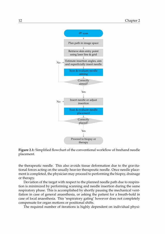
The analysis of the conventional workflow of needle placement presented in thissection is based on clinical attendances at three medical centres, in the Nether-lands and the USA. Fig. 2.1 shows a simplified flowchart of the workflow.
During a typical procedure, the patient is placed on the imager table and gen-eral anaesthesia may be applied. A first set of parallel, transversal images of theregion of interest is acquired by scanning. The physician uses the image set tochoose the target position for the needle tip as well as a suited entry point on thepatient’s skin, yielding the required insertion angles and depth. The needle pathis chosen such that impenetrable structures such as bones and critical structuressuch as larger blood vessels are avoided, and preferably coincides with a trans-versal image plane to facilitate needle placement. For a needle trajectory obliqueto the transversal plane, the gantry of some CT scanners can be tilted to visualizethe entire needle trajectory in a single scan plane.
The next step is to transfer the planned needle path from the virtual 3D imagespace to the patient, starting with the entry point. The imager table is translatedso that the transversal plane of the planned entry point coincides with the projec-ted plane of a laser mounted at the top of the gantry, visualizing the intersectionof this plane with the patient. The position of the entry point along this line isretrieved and marked by the physician based on anatomical references visible inthe images, such as bones, or by using a sheet with radiopaque grid lines placedon the patient’s skin during scanning. Sometimes a minor incision is made be-fore proceeding to insertion to reduce tissue deformation, avoid abrupt needleentry through the skin and prevent entrainment of epithelial cells. If no generalanaesthesia is applied, local anaesthetic may be injected at this point.
Now the physician must transfer the planned insertion angles from the virtual3D image space to the patient and insert the needle accordingly. Longitudinalmarkings on the needle are used to measure the insertion depth. Depending onhis or her confidence and the risk of damaging critical tissues, the physician maychoose to insert the needle in a single stroke or, more typically, employ a stepwiseprocedure with intermediary confirmation scans and angular adjustments. Sincetherapeutic needles can be too long to fit within the geometric constraints of theimager bore when inserted only superficially, it is common practice to use a smal-ler aiming needle to iterate towards the right insertion angle before switching to
12 Chapter 2
0th scan
Retrieve skin entry point using laser line & grid
Plan path in image space
Estimate insertion angles, aim and superficially insert needle
Scan & evaluate needle aiming
Correctly aimed?
Insert needle or adjust insertion
No
Yes
Scan & evaluate needle placement
Correctly placed?
No
Proceed to biopsy or therapy
Yes
Figure 2.1: Simplified flowchart of the conventional workflow of freehand needleplacement.
the therapeutic needle. This also avoids tissue deformation due to the gravita-tional forces acting on the usually heavier therapeutic needle. Once needle place-ment is completed, the physician may proceed to performing the biopsy, drainageor therapy.
Deviation of the target with respect to the planned needle path due to respira-tion is minimized by performing scanning and needle insertion during the samerespiratory phase. This is accomplished by shortly pausing the mechanical vent-ilation in case of general anaesthesia, or asking the patient for a breath-hold incase of local anaesthesia. This ‘respiratory gating’ however does not completelycompensate for organ motions or positional shifts.
The required number of iterations is highly dependent on individual physi-

An overview of systems for CT- and MRI-guided needle placement 13
cian skill, particularly the ability to mentally process the 3D angular informationin the image, transform it to the patient’s reference frame, and then manuallyexecute the desired angulation and insertion.
The iterative process of manual adjustments to needle placement and sub-sequent verification has three direct negative consequences: (1) increased tissuedamage with each erroneous needle insertion, (2) increased radiation exposure ofthe patient and physician with each image scan in case of X-ray based imagingand (3) increased costs and equipment occupation due to increased proceduretime. The smaller and deeper the target, while visible in imaging, the more chal-lenging it is to target and herein lies the motivation to increase procedural speedand accuracy through the development of systems to aid in percutaneous needleplacement.
2.3.2 Needle placement systems
What follows is the result of work to comprehensively identify and catalogueCT- and MRI-guided systems that intend to increase the quality of percutaneousneedle placement in the thorax and abdomen. The systems range from simplepassive aids to fully actuated, imager-integrated robots. They are divided intosystems that supply feedback on placement of the needle to the physician andsystems that supply physical guidance to the needle. The first group is furtherdivided into navigation and tracking systems, systems that use the direction ofgravity as a reference and systems that project a laser as an axis of reference. Thelatter group is divided based on mounting type: patient mounted, table mountedand gantry or floor mounted systems. The found systems are listed in Table 2.1.
Systems that supply only feedback on needle placement
In the current workflow, feedback on needle placement to the physician is sup-plied through the imaging modality, which in case of CT or MR imaging is typic-ally non-real-time and does not allow for simultaneous needle placement adjust-ment. Therefore, one strategy to improve the procedure of percutaneous needleplacement is to supply additional feedback based on other sources than the ima-ging modality.
Navigation & tracking systems Navigation systems supply continuous real-time feedback to the physician on the position and orientation of a needle withrespect to a patient’s anatomy via a graphical representation of the needle in astatic image set and/or a specified target coordinates. This requires a single regis-tration of an image set and continuous registration or tracking of the instrument,both with respect to the same coordinate system. Three types of tracking meth-ods are employed: optical, electromagnetic and mechanical. Fig. 2.2 illustratesthe systems presented in this section.

14 Chapter 2
(a) Stryker [79] optical navigation system. Illus-tration adapted from [80].
(b) ActiViews [81] CT-Guide. Illustration adap-ted from [82].
(c) NDI [83] Aurora. Illustration adapted from[84]. Copyright c© 2007 by AUR. Reproducedby permission of AUR.
(d) Philips [85] Pinpoint. Illustration adaptedfrom [86].
Figure 2.2: Navigation and tracking systems.
Optical tracking is the most commonly used technique in medical navigationsystems. It incorporates infrared cameras to track light reflecting (passive) oremitting (active) markers attached to the instrument. Prior to imaging, severalmarkers are commonly attached to the patient’s skin, which are both visible inthe images and captured by the tracking system to enable registration of an ac-quired image set with respect to the tracking system. Examples of optical trackingsystems are the Claron [87] MicronTracker and the NDI [83] Polaris, which wasused for navigation in phantom studies of CT-guided radiofrequency ablation inthe liver in [88]. The NDI Polaris was also used in [89] to track both an instru-ment and a hand-held system which projects an image-overlay directly onto thetissue as an improved navigation method during open liver ablation. Severalnavigation systems which incorporate an optical tracking system are commer-cially available, e.g. the Stryker [79] Navigation System II and eNlite NavigationSystem, the Medtronic [90] StealthStation, the Pathfinder [91] Explorer and theCAScination [92] CAS-ONE. Optical tracking systems require an unobstructed

An overview of systems for CT- and MRI-guided needle placement 15
line of sight between the cameras and the markers. This may hinder or restrictthe workspace of the physician and equipment.
The ActiViews [81] CT-Guide [82] is an optical tracking system specificallydesigned for CT-guided needle placement. This system incorporates a compactdisposable optical sensor which can be attached to the needle and a sterile stickercontaining markers which can be identified in images from both CT and the op-tical sensor. The sticker is applied over the retrieved needle entry point on thepatient’s skin after planning of the needle path using a first set of CT images. Asecond set of CT images is obtained to perform a first one-time registration ofthe sticker with respect to the CT image set. The optical sensor is used to sub-sequently track the needle with respect to the sticker. Compared to conventionaloptical tracking systems, the ActiViews system is more compact, has a shorterline of sight between camera and markers which is less easily obstructed andintegrates into the current workflow. Subsequent needle placement through adifferent entry point requires relocation of the sticker and repeated CT scanning.
Electromagnetic tracking systems consist of a generator of a controlled, chan-ging magnetic field and an electromagnetic sensor containing one or multiplecoils that is attached to the instrument. The position and orientation of the sensorand, thus, that of the instrument, with respect to the generator can be derivedfrom the measured electromagnetic induction in the coils. Examples are theMedtronic [90] AxiEM and the NDI [83] Aurora. The latter system was usedto track a needle with respect to a registered set of images in both phantom stud-ies [84, 93–95] and patient studies [96–98]. While electromagnetic tracking sys-tems are unaffected by an obstructed line of sight, the presence of neighbouringmetallic objects and other fields may seriously distort the magnetic field and in-crease registration errors.
Alternatively, a mechanical linkage with encoders on its joints can be usedto track an instrument. This concept is used in the Philips [85] Pinpoint sys-tem [86,99,100] which includes a needle guide at the tip of a passive, non-lockableImmersion [101] MicroScribe-G2X arm with five DOFs. Its base is fixed with re-spect to the imager gantry.
Systems that use the direction of gravity as a reference The direction of gravitycan serve as a reference vector for the orientation of a planned axial trajectory. Theimager table, the front face of the imager gantry or a laser line projected by theimager can serve as a second reference: rotation about the vector of gravity. Withrespect to these two reference vectors, a needle guide can be oriented such that itis parallel to the planned needle path, typically using a tool to indicate the relativeangles. Maintaining this orientation, the needle guide can then be positioned tocoincide with the entry point on the patient’s skin, yielding full alignment withthe planned needle path. Finally, insertion of the needle along the axial trajectoryof the needle guide is easily measured using markings on the needle. This is thegeometric method used in the systems presented in this paragraph, which are

16 Chapter 2
(a) Palestrant I. Illustration adapted from [102]. (b) Palestrant II. Illustration adapted from [103].
(c) Zhang et al. Illustration adapted from [104]. (d) INRAD [105] AccuPlace. Illustration adap-ted from [106].
Figure 2.3: Systems that use the direction of gravity as a reference.
illustrated in Fig. 2.3.The use of the direction of gravity as a reference was applied in two needle
guidance systems for CT-guided drainage and biopsy by Palestrant. The first sys-tem [102] embodies a two dimensional bubble level on a hand-held plateau withrespect to which the angle of a needle guide about one axis can be set using aprotractor, a common instrument to measure angles. The bubble level providesfeedback on the orientation of the plateau for manual adjustment. A ruler is at-tached to the needle guide to determine the insertion depth. The system wasshown to minimize trauma and decreased time for CT scanning in biopsy anddrainage procedures in 40 patients [107]. The second system by Palestrant [103]embodies a needle guide attached to a hand-held protractor which can be manu-ally rotated to the correct angle with respect to a pendulum. A two-dimensionalversion of the latter is patented by Zhang et al. [104].
The INRAD [105] AccuPlace [106] is a patented disposable commerciallyavailable system with the same functional concept. It is available in two versions,with a one and a two dimensional bubble level respectively. It relies on markingson the needle to determine the insertion depth.

An overview of systems for CT- and MRI-guided needle placement 17
Systems that project a laser as an axis of reference Several systems project alaser along the planned needle trajectory, creating an axial reference in order tofacilitate manual needle placement. First the tip of the needle is placed to coin-cide with the intersection of the laser with the skin, then the hub of the needleis aligned with the laser line and the needle inserted manually using markers onthe needle to determine the insertion depth. Fig. 2.4 illustrates the laser projectionsystems presented in this section.
Frederick et al. developed a system in which the axial reference is formedby the intersection of two planes of light [108, 116]. The system consists of twomechanisms fixed at the base with respect to the imager. Each mechanism con-tains protractors and rulers related to the coordinate system of the imager formanual adjustment of the placement of one plane of light. This system and theupcoming systems in this category use translation of the imager table in the dir-ection of the gantry to position the patient with respect to the axial laser referenceas part of its alignment with the planned needle path.
A small hand-held housing that projects a laser line as a reference for theneedle path is presented by Ishizaka et al. [117]. The system needs to first bemanually aligned with the front face of the gantry and then oriented to the cor-rect insertion angle using a protractor and a pendulum indicator. Since the laserline is always kept parallel to this front face, the gantry must be tilted for laserguided needle placement oblique to the transversal plane.
A system by Unger et al. [109] comprises a laser module which can be courselypositioned around the patient by movement along two perpendicular horizontalrails. The module embodies several motion stages, mechanical constructions thatallow motion in one or more directions whereas motion in other directions isconstrained. Two perpendicular rotational stages and two perpendicular lin-ear stages equipped with micrometers enable precise manual adjustment of theplacement of the laser line in accordance with values determined by path plan-ning using the images. A higher placement accuracy compared to freehand hasbeen demonstrated in a phantom model [118].
The LAP [110] Patpos Invent [119, 120] is a variation of the system by Un-ger et al. The horizontal rail that holds the laser module is attached to the im-ager gantry above the patient. Like the system by Ishizaka et al. [117], gantrytilting is required for laser guided needle placement oblique to the transversalplane. A phantom study [111] showed improved accuracy with use of the sys-tem among inexperienced participants, whereas no significant improvement wasfound among experienced physicians. In a patient study [121], the system yiel-ded a reduction in number of scans, number of needle placement corrections,targeting error and procedure duration. An extension of the system adds a ver-tical rail between the horizontal rail and the laser module to increase the range ofthe system. A similar system registered with the CT imager and with automatedtranslation and rotation of the laser was patented by Siemens [35, 122].
The commercially available NeoRad [112] SimpliCT [113,123,124] is very sim-ilar to the system by Unger et al. [109], but streamlined. This system embodies a

18 Chapter 2
(a) Frederick et al. Illustration adapted from[108].
(b) Unger et al. Illustration adapted from [109].
(c) LAP [110] Patpos Invent. Illustration from[111]. Copyright c© 1999 by Springer-Verlag Ber-lin Heidelberg. Reproduced by permission ofSpringer-Verlag Berlin Heidelberg.
(d) NeoRad [112] SimpliCT. Illustration adaptedfrom [113].
(e) Amedo [114] LNS. Illustration adapted from[115]. Copyright c© 2013 by Elsevier Inc. Repro-duced by permission of Elsevier Inc.
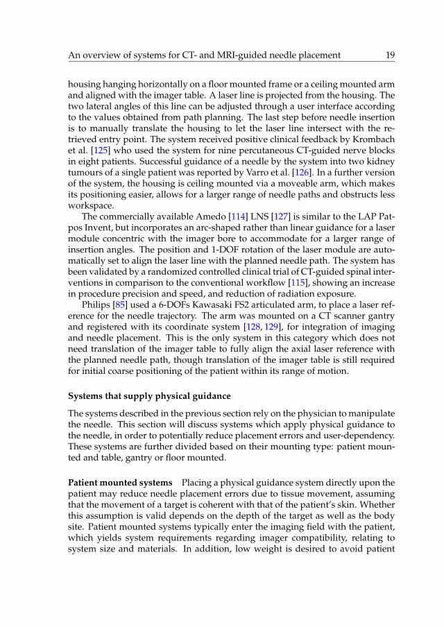
Figure 2.4: Systems that project a laser as an axis of reference.
An overview of systems for CT- and MRI-guided needle placement 19
housing hanging horizontally on a floor mounted frame or a ceiling mounted armand aligned with the imager table. A laser line is projected from the housing. Thetwo lateral angles of this line can be adjusted through a user interface accordingto the values obtained from path planning. The last step before needle insertionis to manually translate the housing to let the laser line intersect with the re-trieved entry point. The system received positive clinical feedback by Krombachet al. [125] who used the system for nine percutaneous CT-guided nerve blocksin eight patients. Successful guidance of a needle by the system into two kidneytumours of a single patient was reported by Varro et al. [126]. In a further versionof the system, the housing is ceiling mounted via a moveable arm, which makesits positioning easier, allows for a larger range of needle paths and obstructs lessworkspace.
The commercially available Amedo [114] LNS [127] is similar to the LAP Pat-pos Invent, but incorporates an arc-shaped rather than linear guidance for a lasermodule concentric with the imager bore to accommodate for a larger range ofinsertion angles. The position and 1-DOF rotation of the laser module are auto-matically set to align the laser line with the planned needle path. The system hasbeen validated by a randomized controlled clinical trial of CT-guided spinal inter-ventions in comparison to the conventional workflow [115], showing an increasein procedure precision and speed, and reduction of radiation exposure.
Philips [85] used a 6-DOFs Kawasaki FS2 articulated arm, to place a laser ref-erence for the needle trajectory. The arm was mounted on a CT scanner gantryand registered with its coordinate system [128, 129], for integration of imagingand needle placement. This is the only system in this category which does notneed translation of the imager table to fully align the axial laser reference withthe planned needle path, though translation of the imager table is still requiredfor initial coarse positioning of the patient within its range of motion.
Systems that supply physical guidance
The systems described in the previous section rely on the physician to manipulatethe needle. This section will discuss systems which apply physical guidance tothe needle, in order to potentially reduce placement errors and user-dependency.These systems are further divided based on their mounting type: patient moun-ted and table, gantry or floor mounted.
Patient mounted systems Placing a physical guidance system directly upon thepatient may reduce needle placement errors due to tissue movement, assumingthat the movement of a target is coherent with that of the patient’s skin. Whetherthis assumption is valid depends on the depth of the target as well as the bodysite. Patient mounted systems typically enter the imaging field with the patient,which yields system requirements regarding imager compatibility, relating tosystem size and materials. In addition, low weight is desired to avoid patient

20 Chapter 2
(a) Chang et al. Illustration adapted from [130]. (b) Neorad [112] Simplify. Illustration adaptedfrom [131].
(c) Apriomed [132] SeeStar. Illustration adaptedfrom [133].
(d) Robopsy. Illustration adapted from [134].
Figure 2.5: Patient mounted systems that supply physical guidance.
discomfort. Fig. 2.5 illustrates the patient mounted physical guidance systemspresented in this section.
A patent by Chang et al. [130] describes one of the simplest patient moun-ted needle guidance systems. It embodies a flat adhesive plateau which canbe attached to the patient’s skin centred around the retrieved entry point. Ontop of the plateau is a mechanism which allows for a needle guide to be manu-ally rotated about two orthogonal axes intersecting with the entry point. Theneedle guide can be locked once a correct orientation has been achieved. TheNeorad [112] Simplify [131] and Apriomed [132] Seestar [138] are comparablecommercially available systems.
The Neorad [112] Simplify [131] system consists of a pivoting arc that allowsrotation of the needle guide. The system does not directly help to aim the needle,but merely holds a needle in place to allow for imaging before or during needleinsertion without the need for a physician to manually hold the needle, avoidingradiation exposure to the physician.
The same benefits are offered by the Apriomed [132] Seestar [133,138], whose

An overview of systems for CT- and MRI-guided needle placement 21
(e) Song et al. Illustration adapted from [135].Copyright c© 2013 by IEEE. Reproduced by per-mission of IEEE.
(f) CT-Bot. Illustration adapted from [136].
(g) LPR. Illustration from [137]. Copyright c©2008 by IEEE. Reproduced by permission ofIEEE.
Figure 2.5: Patient mounted systems that supply physical guidance – continued.
mechanism consists of two perpendicular pivoting arcs over which a needleguide can be moved and locked. In addition, the system incorporates a metaltube which yields deliberate streaking in CT images to indicate the current axisof guidance. In a patent describing the Seestar [139], a variation of the system ispresented consisting of a needle guide on a partial sphere which can rotate on ahalf dome and can be locked. In contrast to the system by Chang and the Simplifysystem, the Seestar cannot be removed after needle insertion without retractionof the needle, which is a limitation.
The Robopsy system [134, 140] for CT-guided percutaneous biopsies has akinematic construction which is identical to that of the Apriomed Seestar andis equipped with two electrical stepper motors for active needle aiming. Two ad-ditional stepper motors allow for automated clamping and releasing of a needleand its insertion. This allows a needle to move with organ motion after inser-tion and removal of the system without retraction of the needle. The system can

22 Chapter 2
be placed such that the four motors are located outside the transversal planesaround the needle trajectory to avoid image distortion. Means for registrationwere not included yet, but course manual alignment of the system with the im-ager’s axes facilitates remote manual control of the needle with feedback fromCT images through a graphical user interface. Targeting of a lesion during anin vivo porcine trial was successfully accomplished using a total of four imagescans [141]. Wu et al. subsequently developed a spherical needle manipulatormounted on an MRI loop coil [142]. Piezo stepper motors automate its two DOFsand registration with the imager is performed through six spherical fiducials.
Yet another 2-DOFs manipulator fitted onto an MRI loop coil was developedby Song et al. [135]. It contains a needle guide which can be oriented about twoaxes through manual rotation of two serially stacked rings. After registration ofthe system with the MRI scanner, the required rotation angles of the rings corres-ponding to the planned needle path can be calculated automatically and manu-ally set using protractors.
The CT-Bot [136, 143, 144] comprises a CT-guided, 5-DOFs parallel mechan-ism actuated using ultrasonic piezo motors. It uses a fiducial configuration forregistration of the robot with the imager. The mechanism aligns a 2-DOFs needledriver which automates insertion and spinning of the needle. Haptic control overneedle insertion is incorporated.
The CT and MRI compatible Light Puncture Robot (LPR) [137, 145] embodiesa patient mounted active needle insertion stage which can be oriented about twoaxes. Four actuators on a frame fixed to the imager table are connected to thestage via straps to enable automated movement of the stage over the patientsabdomen. Registration of the system with a CT imager is performed using afiducial configuration. The actuators of the system are custom pneumatic steppermotors. A further version of the system is under development [146]. Both theLPR and the CT-Bot [143,144] occupy a significant part of the imager bore, leavinglittle space for the patient.
Table, gantry & floor mounted systems Table, gantry and floor mounted sys-tems that provide physical guidance help placing a needle along a linear traject-ory fixed with respect to the imager gantry or table coordinate system rather thanthe patient’s skin. Table mounted systems, like patient mounted systems, typic-ally enter the imaging field, yielding system requirements on imager compatib-ility. Fig. 2.6 and Fig. 2.7 illustrate the table, gantry and floor mounted systemspresented in this section.
Bard [147] developed the CT Guide [148, 156], a table mounted stereotacticframe for needle placement. It consists of a base which is fixated between thetable and the patient, a linear slide parallel to the table, an arc-shaped arm whichcan pivot about a first axis with respect to the slider, and a needle guide whichcan be positioned along the slider and pivot about a second axis. The angle ofthe arc-shaped arm and the needle guide can be determined by protractors. The

An overview of systems for CT- and MRI-guided needle placement 23
(a) Bard [147] CT Guide. Illustration adaptedfrom [148].
(b) Christoforou et al. Illustration adapted from[149]. Copyright c© 2013 by John Wiley & Sons,Ltd. Reproduced by permission of John Wiley &Sons, Ltd.
(c) Siemens [35]. Illustration adapted from [150]. (d) iSYS Medizintechnik [151] iSYS1. Illustrationadapted from [152].
(e) AcuBot. Illustration adapted from [153]. (f) INNOMEDIC [154] INNOMOTION. Illustra-tion adapted from [155]. Copyright c© 2008 byIEEE. Reproduced by permission of IEEE.
Figure 2.6: Table mounted systems that supply physical guidance.

24 Chapter 2
needle guide includes an engagement mechanism and a ruler to determine theinsertion depth. The system could not be used in 32% of 107 patients involvedin a clinical test [157], primarily due to the constraints posed by the system onpatient size or the need for a lateral needle path. When the system was used itdecreased the number of iterations needed to correctly place the needle.
To avoid issues related to MRI compatibility, manual actuation was chosen fora manipulator developed by Christoforou et al. [149]. The system is designed tofit in between patient and imager bore and contains five DOFs to place a needleguide. Two thin tubes filled with gadolinium contrast agent are attached to itsend effector parallel to the needle to indicate its placement in the images whichare used for feedback on its placement. A sixth DOF for needle insertion is con-nected via cables to a crank on a hand-held unit.
A system by Siemens [35,150,158] includes a needle guide on an active 2-DOFsremote centre of motion mechanism, consisting of a pivoting parallelogram. Themechanism can be placed and held by an arm such that the remote centre ofmotion coincides with the retrieved entry point.
The iSYS Medizintechnik [151] iSYS1 [152] evolved from the Biopsy RobotI and II systems. The system embodies a needle guide which is connected inparallel to two stacked actuated XY stages, which enable 2-DOFs lateral position-ing and 2-DOFs lateral orienting. A mechanical arm is used to lock the systemafter coarse manual placement near the site of the intervention. Placement of theneedle guide can then remotely controlled under live imaging without X-ray ex-posure to the physician. Included is a fiducial marker configuration consisting oftwo parallel rings concentric with the needle guide. Using live image guidance ofa C-arm cone beam CT, which can automatically align its imaging direction withthe planned needle path, the needle guide can be appropriately placed in twosteps. First the top XY stage is moved until both fiducial rings appear concentricin the image, indicating the axis of the needle guide is parallel to the plannedneedle path. Then the lower XY stage is moved to perform a lateral translationof the needle guide until both fiducial rings appear concentric in the image withthe planned needle path, implying the axis of the needle guide is coincident withthe planned needle path. Subsequent needle insertion through the needle guideis performed manually.
The AcuBot [153, 159] is a 5-DOFs robotic needle placement system placed ona bridge frame over the patient. The system consists of a 3-DOFs linear XYZ stageto position a 2-DOFs remote centre of motion mechanism with a needle guide. Inaddition, a subsystem for automated gripping, insertion and axial rotation of theneedle has been developed [160]. A fiducial configuration of seven aluminiumrods is connected to the system’s end effector. The rods form three Z-shapedmotifs which enable registration with the imager through a single image scan ina wide range of rotations [161].
The Innomedic [154] INNOMOTION [155, 162] is a CT and MRI compatiblerobotic system for needle placement. The system incorporates a 2-DOFs remotecentre of motion mechanism identical to the one used by Siemens [35, 150, 158].
An overview of systems for CT- and MRI-guided needle placement 25
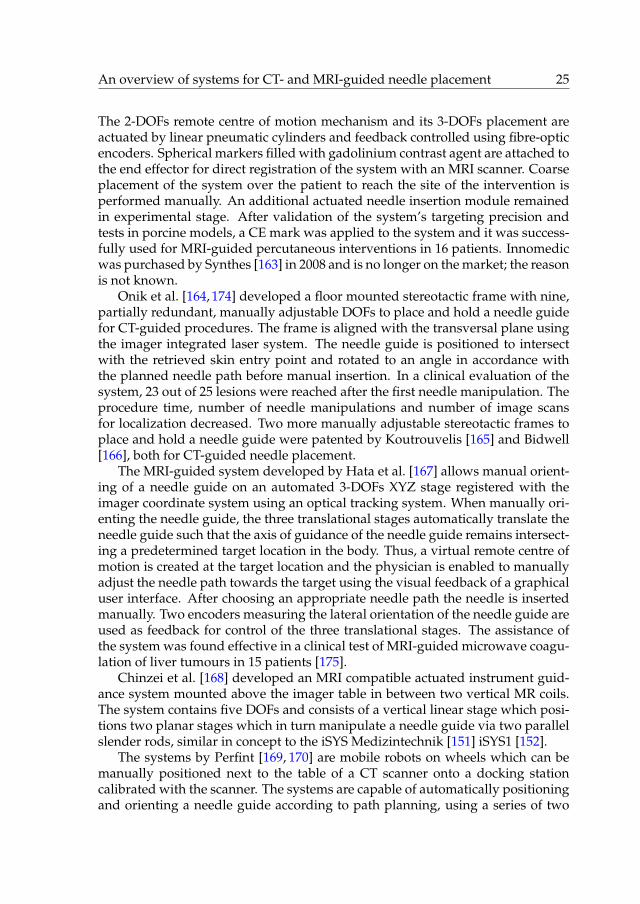
The 2-DOFs remote centre of motion mechanism and its 3-DOFs placement areactuated by linear pneumatic cylinders and feedback controlled using fibre-opticencoders. Spherical markers filled with gadolinium contrast agent are attached tothe end effector for direct registration of the system with an MRI scanner. Coarseplacement of the system over the patient to reach the site of the intervention isperformed manually. An additional actuated needle insertion module remainedin experimental stage. After validation of the system’s targeting precision andtests in porcine models, a CE mark was applied to the system and it was success-fully used for MRI-guided percutaneous interventions in 16 patients. Innomedicwas purchased by Synthes [163] in 2008 and is no longer on the market; the reasonis not known.
Onik et al. [164, 174] developed a floor mounted stereotactic frame with nine,partially redundant, manually adjustable DOFs to place and hold a needle guidefor CT-guided procedures. The frame is aligned with the transversal plane usingthe imager integrated laser system. The needle guide is positioned to intersectwith the retrieved skin entry point and rotated to an angle in accordance withthe planned needle path before manual insertion. In a clinical evaluation of thesystem, 23 out of 25 lesions were reached after the first needle manipulation. Theprocedure time, number of needle manipulations and number of image scansfor localization decreased. Two more manually adjustable stereotactic frames toplace and hold a needle guide were patented by Koutrouvelis [165] and Bidwell[166], both for CT-guided needle placement.
The MRI-guided system developed by Hata et al. [167] allows manual orient-ing of a needle guide on an automated 3-DOFs XYZ stage registered with theimager coordinate system using an optical tracking system. When manually ori-enting the needle guide, the three translational stages automatically translate theneedle guide such that the axis of guidance of the needle guide remains intersect-ing a predetermined target location in the body. Thus, a virtual remote centre ofmotion is created at the target location and the physician is enabled to manuallyadjust the needle path towards the target using the visual feedback of a graphicaluser interface. After choosing an appropriate needle path the needle is insertedmanually. Two encoders measuring the lateral orientation of the needle guide areused as feedback for control of the three translational stages. The assistance ofthe system was found effective in a clinical test of MRI-guided microwave coagu-lation of liver tumours in 15 patients [175].
Chinzei et al. [168] developed an MRI compatible actuated instrument guid-ance system mounted above the imager table in between two vertical MR coils.The system contains five DOFs and consists of a vertical linear stage which posi-tions two planar stages which in turn manipulate a needle guide via two parallelslender rods, similar in concept to the iSYS Medizintechnik [151] iSYS1 [152].
The systems by Perfint [169, 170] are mobile robots on wheels which can bemanually positioned next to the table of a CT scanner onto a docking stationcalibrated with the scanner. The systems are capable of automatically positioningand orienting a needle guide according to path planning, using a series of two

26 Chapter 2
(a) Onik et al. Illustration adapted from [164]. (b) Koutrouvelis. Illustration adapted from[165].
(c) Bidwell. Illustration adapted from [166]. (d) Hata et al. Illustration adapted from [167].Copyright c© 2008 by Wiley-Liss, Inc. Repro-duced by permission of Wiley-Liss, Inc.
(e) Chinzei et al. Illustration adapted from[168]. Copyright c© 2000 by Springer-Verlag Ber-lin Heidelberg. Reproduced by permission ofSpringer-Verlag Berlin Heidelberg.
(f) Perfint [169] ROBIO. Illustration adaptedfrom [170].
Figure 2.7: Gantry and floor mounted systems that supply physical guidance.

An overview of systems for CT- and MRI-guided needle placement 27
(g) Yanof et al. Illustration adapted from [171]. (h) Zhou et al. Illustration adapted from [172].Copyright c© 2012 by John Wiley & Sons, Ltd.Reproduced by permission of John Wiley &Sons, Ltd.
(i) Tovar-Arriaga et al. Illustration adapted from[173]. Copyright c© 2011 by John Wiley & Sons,Ltd. Reproduced by permission of John Wiley &Sons, Ltd.
Figure 2.7: Gantry and floor mounted systems that supply physical guidance –continued.
or three orthogonal linear stages and two orthogonal rotational stages. The endeffector of the system is an automated gripper for a disposable needle guide.Insertion of the needle through the guide is performed manually, after which thegripper can be opened for release. Registration of the system with respect tothe CT scanner coordinate system is performed through fiducials on the dockingstation which are captured by a camera in the bottom of the mobile system and adual axis tilt sensor.
The same CT-integrated articulated robot used by Wood et al. [128, 129] waspreviously equipped with a pneumatic needle gripper to automate needle place-ment including automated needle insertion by Yanof et al. [176]. A load cellwas later added to the needle gripper to allow for haptic control on needle in-sertion [171, 177].

28 Chapter 2
A Mitsubishi RV-E2 6-DOFs articulated robot was used in a setup by Zhouet al. [178] to investigate CT-guided automated needle placement for biopsy oflung nodules during respiratory motion. The end effector of the floor mountedrobot is a needle gripper at the tip of a 460 mm long acetal beam used to reachinside the imager bore. This is the only listed system in which manipulation ofthe needle is continuously compensated for respiratory motion which is trackedby a vision system. In a preliminary test, an 18 gauge needle was inserted 300times along different trajectories up to 160 mm long in a phantom undergoingrigid body movement simulating respiration, resulting in a targeting accuracy of0.5�0.1 mm [172].
Tovar-Arriaga et al. [173, 179] present a system consisting of a 7-DOFsDLR/KUKA Light Weight Robot III equipped with a needle guide and registeredwith an angiographic C-arm using an optical tracking system. The system offersvarious placement methods, including automated needle guide placement ac-cording to planning with subsequent manual adjustment of the skin entry pointthrough remote control, while maintaining its aim at the chosen target for theneedle tip, a function similar to that of the system by Hata et al. [167].
2.4 Discussion
An overview of over forty existing systems for image-guided percutaneousneedle placement in the torso has been presented, ranging from simple passiveaids, with minimal interference in existing workflows, to fully actuated imager-integrated robots, which take over full control of needle placement.
Navigation systems can be used to provide feedback on needle placement tothe physician through a graphical user interface. Manipulation of the needle bythe physician makes this type of system versatile yet also user-dependent. Whilethese systems occupy relatively little space directly around the patient, they dohave a footprint in the imaging suite and require an unobstructed line of sight oran undistorted magnetic field. The ActiViews [81] CT-Guide [82] offers a cheaperalternative that effectively eliminates this issue with a tiny, disposable system.
Systems that use the direction of gravity as a reference to orient a needle canalso be relatively small, simple and low cost, with minor impact on existing work-flows. The INRAD [105] AccuPlace [106] is one of the most simple and compact ofall discussed systems. However, this type of system requires manual alignmentwith both the direction of gravity and the imager table or gantry during needleinsertion.
Systems that project a laser as an axial reference can be effective with littleinterference with existing workflows. Alignment of the axial reference accordingto the planned trajectory is fully separated from needle manipulation, facilitatingneedle placement. Furthermore, there is no physical contact at any point in theprocedure between the system and the needle or the patient, avoiding additionalsterilization procedures. A 6-DOFs robot, as used by Wood et al. [128, 129], is a

An overview of systems for CT- and MRI-guided needle placement 29
complex way to manipulate the 4-DOFs laser reference. Taking advantage of theimager gantry tilt and imager table translation, the Amedo LNS [114, 115, 127]needs only two automated imager-integrated DOFs to accomplish equal func-tionality. The commercially available Neorad [112] SimpliCT [113,123–126] evid-ences a particularly streamlined design, that wheels away when not in use.
Patient mounted systems can be very small, simple and low-cost, as illus-trated by the designs of the two commercially available systems Neorad [112]Simplify [131] and the Apriomed [132] Seestar [133, 138, 139], and the actuatedRobopsy system [134, 140, 141]. Attempts to create 5- or 6-DOFs actuated patientmounted systems have led to rather unusual and complex designs which occupya large volume of an already limited space. Part of the rationale behind patientmounting is the assumption that the skin and target move as a rigid body, suchthat respiratory motion is inherently compensated for. The validity of this as-sumption however quickly expires with increasing needle insertion depth, due tothe flexible body movement of the torso and sliding motion of abdominal organswith respect to the skin by respiration and the forces for physical guidance and in-sertion of the needle. Patient mounting however does provide inherent safety incase of patient movement, since system and needle freely move with the patient’sskin. A weakness of patient mounted systems and systems which do not provideany physical guidance, is the application of forces to the torso upon needle in-sertion other than the axial component. This may result in tissue movement anddeformation and, consequently, needle placement errors. Table, gantry and floormounted systems avoid this by transmitting the guidance forces through a stiffmechanical construction. These however generally occupy more space and theirusage may hinder patient access and require changes to the current workflow.While this is the largest category of systems, only the iSYS Medizintechnik [151]iSYS1 [152] and Perfint [169, 170] systems are currently commercially available.
Imager compatible systems that supply physical guidance and active needleinsertion can be remotely controlled to provide the opportunity of needle manip-ulation under real-time imaging. This avoids the need for a physician to enterthe imaging field, which is confined by the imager bore and hazardous in case ofradiological imaging. Real-time imaging is especially useful for continuous mon-itoring during high risk needle insertions. In systems with active needle insertion,haptic control should be integrated to account for the demands of a physician tofeel needle tissue interaction, e.g. as experimented with in the system by Yanofet al. [171, 176, 177] or the CT-Bot [136, 143, 144]. In addition, more advanced sys-tems could automatically adapt for respiratory motion during insertion to avoidthe need for breath holding, as proposed e.g. by Zhou et al. [172, 178], or com-pensate for tissue movement and needle deflection by implementing means forneedle steering to further reduce placement errors. However, such advancementsare still in the research stage and will likely lead to increased system costs andcomplexity, from a technical point of view, as well as with regards to productcertification, which may outweigh the benefits.
The presented overview shows that there is a wide variety of developed sys-

30 Chapter 2
tems with growing complexity. However, given that only few systems havereached commercial availability, it is clear that the technical community is strug-gling to develop solutions that are clinically adopted. The question rises: why isthis so?
In the authors’ personal experience, freehand percutaneous needle placementis generally perceived by clinicians as sufficient to achieve satisfactory patientoutcomes. While improved accuracy is a goal of many systems, it has not beenclearly demonstrated that the accuracy obtained by clinicians’ manual skill is alimiting factor to procedural success in terms of patient outcome. Furthermore,freehand needle placement employs minimal equipment and image-guided pro-cedures typically reimburse at fixed amounts. Adding any systems into the pro-cedure is therefore rightfully seen by healthcare providers as increasing complex-ity and costs.
To emphasize the added value of a system, we recommend the developmentof a comprehensive standard method of assessing and reporting the perform-ance to cost ratio, taking into account patient outcome, time for needle place-ment, time for system installation, equipment costs and sterilization proceduresamongst others. Technically relevant parameters such as needle properties, in-sertion angles and depth, penetrated tissue layers, X-ray exposure (if applicable)and number of iterations and final placement errors should be uniformly definedand clearly specified. The results of freehand needle placement at multiple clin-ical centres should act as a benchmark. This enables the technical communityto generate a complete and adequate set of system requirements and enables themedical community to evaluate the overall merit of a specific system.
In conclusion, it is clear that none of the systems discussed, while many aretechnically sound, represent a breakthrough in percutaneous procedures on parwith that of the imaging technology that made them possible. Thus, there is stillopen space for innovation and readers are invited to draw their own conclusionsas to the art’s direction.

An overview of systems for CT- and MRI-guided needle placement 31
Tabl
e2.
1:Li
sted
over
view
ofne
edle
plac
emen
tsys
tem
s.Sp
ecifi
edar
eth
eco
mm
erci
alav
aila
bilit
y(a
tthe
tim
eof
arti
cle
subm
issi
onan
dto
the
best
ofth
eau
thor
s’kn
owle
dge)
,suc
cess
ive
geom
etri
cst
eps
and
corr
espo
ndin
gnu
mbe
rofd
egre
esof
free
dom
,act
uati
onty
pe(a
bbre
viat
edby
‘P’f
orPa
ssiv
ean
d‘A
’for
Act
ive)
and
refe
renc
ean
d/or
feed
back
sour
ce.
Syst
emC
om.
avai
labl
eG
eom
etri
cst
ep(s
)#
DO
FsA
ct.
Ref
eren
ceor
feed
back
sour
ce
Con
vent
iona
lwor
kflow
-
Posi
tion
need
leti
p
Set l
ater
alor
ient
atio
nne
edle
Inse
rtne
edle
3 2 1
P P P
Skin
entr
ypo
int
Pati
enta
nato
my
and
imag
es
Nee
dle
rule
r
Nav
igat
ion
&tr
acki
ngsy
stem
s
Nav
igat
ion
and
trac
king
syst
ems
[79,
83,8
4,86
–100
]Ye
s
Reg
iste
rim
age
setw
ith
syst
em
Posi
tion
need
leti
p
Setl
ater
alor
ient
atio
nne
edle
Inse
rtne
edle
6 3 2 1
- P P P
Fidu
cial
confi
gura
tion
Vis
ualiz
atio
n
Vis
ualiz
atio
n
Vis
ualiz
atio
nan
d/or
need
leru
ler
Act
iVie
ws
[81]
CT-
Gui
de[8
2]Ye
s
Plac
est
icke
r
Posi
tion
need
leti
p
Setl
ater
alor
ient
atio
nne
edle
Inse
rtne
edle
6 3 2 1
P P P P
Skin
entr
ypo
int
Stic
ker
Vis
ualiz
atio
n
Vis
ualiz
atio
nan
d/or
need
leru
ler
Syst
ems
that
use
the
dire
ctio
nof
grav
ity
asa
refe
renc
e
Pale
stra
ntI
[102
,107
],
INR
AD
[105
]
Acc
uPla
ce[1
06]
Yes
Setl
ater
alor
ient
atio
nne
edle
guid
e
Plac
eba
seon
skin
Leve
lbas
e
Alig
nba
se
Inse
rtne
edle
1 3 2 1 1
P P P P P
Prot
ract
or
Skin
entr
ypo
int
Bubb
lele
vel
Imag
erta
ble,
lase
ran
d/or
gant
ry
Rul
er
Con
tinue
don
next
page
.

32 Chapter 2Ta
ble
2.1
–C
ontin
ued
from
prev
ious
page
.
Syst
emC
om.
avai
labl
eG
eom
etri
cst
ep(s
)#
DO
FsA
ct.
Ref
eren
ceor
feed
back
sour
ce
Pale
stra
ntII
[103
]N
o
Setl
ater
alor
ient
atio
nne
edle
guid
e
Leve
lbas
e
Alig
nba
se
Plac
eba
se
Inse
rtne
edle
1 2 1 3 1
P P P P P
Prot
ract
or
Pend
ulum
Imag
erta
ble,
lase
ran
d/or
gant
ry
Skin
entr
ypo
int
Rul
er
Zha
nget
al.
[104
]N
o
Setl
ater
alor
ient
atio
nne
edle
guid
e
Leve
lbas
e
Alig
nba
se
Plac
eba
se
Inse
rtne
edle
1 2 1 3 1
P P P P P
Prot
ract
or
Two
pend
ulum
san
dpr
otra
ctor
Imag
erta
ble,
lase
ran
d/or
gant
ry
Skin
entr
ypo
int
Nee
dle
rule
r
Syst
ems
that
proj
ecta
lase
ras
anax
isof
refe
renc
e
Fred
eric
ket
al.
[108
,116
]N
o
Reg
iste
rsy
stem
wit
him
ager
Posi
tion
lase
rm
odul
e1
Ori
entl
aser
mod
ule
1
Posi
tion
lase
rm
odul
e2
Ori
entl
aser
mod
ule
2
Posi
tion
imag
erta
ble
5 2 1 1 1 1
- P P P P A
Unk
now
n
Two
rule
rs
Bubb
lele
vela
ndpr
otra
ctor
Rul
er
Bubb
lele
vela
ndpr
otra
ctor
Enco
der
Ishi
zaka
etal
.
[117
]N
o
Tilt
gant
ry
Plac
ela
ser
mod
ule
Ori
entl
aser
mod
ule
Posi
tion
lase
rm
odul
e
Posi
tion
imag
erta
ble
1 3 1 1 1
A P P P A
Imag
eren
code
r
Gan
try
fron
tpla
ne
Pend
ulum
and
prot
ract
or
Skin
entr
ypo
int
Enco
der
Con
tinue
don
next
page
.

An overview of systems for CT- and MRI-guided needle placement 33
Tabl
e2.
1–
Con
tinue
dfr
ompr
evio
uspa
ge.
Syst
emC
om.
avai
labl
eG
eom
etri
cst
ep(s
)#
DO
FsA
ct.
Ref
eren
ceor
feed
back
sour
ce
Ung
eret
al.
[109
,118
]N
o
Setl
ater
alor
ient
atio
nla
ser
mod
ule
Setc
oars
epo
siti
onla
ser
mod
ule
Setfi
nepo
siti
onla
ser
mod
ule
2 2 2
P P P
Two
prot
ract
ors
Skin
entr
ypo
inta
nd/o
rtw
oru
lers
Skin
entr
ypo
inta
nd/o
rtw
oru
lers
LAP
[110
] Pat
pos
Inve
nt
[111
,119
–121
]N
o
Reg
iste
rsy
stem
wit
him
ager
Tilt
gant
ry
Setl
ater
alor
ient
atio
nla
ser
mod
ule
Posi
tion
lase
rm
odul
e
2 1 1 1
- A P P
Unk
now
n
Enco
der
Prot
ract
or
Rul
eran
d/or
skin
entr
ypo
int
Siem
ens
[35,
122]
No
Reg
iste
rsy
stem
wit
him
ager
Tilt
gant
ry
Posi
tion
lase
rm
odul
e
Setl
ater
alor
ient
atio
nla
ser
mod
ule
Posi
tion
imag
erta
ble
2 1 1 1 1
- A A A A
Unk
now
n
Enco
der
Enco
der
Enco
der
Enco
der
Neo
rad
[112
] Sim
pliC
T
[113
,123
–126
]Ye
s
Posi
tion
and
alig
nba
se
Setl
ater
alor
ient
atio
nla
ser
mod
ule
Posi
tion
imag
erta
ble
Posi
tion
lase
rm
odul
e
6 2 1 1
P A A P
Lase
rpl
ane
and
tabl
e
Enco
ders
Skin
entr
ypo
int
Skin
entr
ypo
int
Am
edo
LNS
[114
,115
,127
]Ye
s
Reg
iste
rsy
stem
wit
him
ager
Tilt
gant
ry
Posi
tion
lase
rm
odul
e
Ori
entl
aser
mod
ule
Posi
tion
imag
erta
ble
2 1 1 1 1
- A A A A
Unk
now
n
Enco
der
Enco
der
Enco
der
Enco
der
Woo
det
al.
[ 128
,129
]N
oR
egis
ter
syst
emw
ith
imag
er
Plac
ela
ser
mod
ule
6 6
- A
Fidu
cial
poin
tmat
chin
g
Enco
ders
All
lase
rsy
stem
s-
Alig
nne
edle
Inse
rtne
edle
4 1
P P
Lase
rlin
eor
inte
rsec
tion
Nee
dle
rule
r
Con
tinue
don
next
page
.

34 Chapter 2Ta
ble
2.1
–C
ontin
ued
from
prev
ious
page
.
Syst
emC
om.
avai
labl
eG
eom
etri
cst
ep(s
)#
DO
FsA
ct.
Ref
eren
ceor
feed
back
sour
ce
Pati
entm
ount
edsy
stem
sth
atsu
pply
phys
ical
guid
ance
Cha
nget
al.
[130
]N
o
Plac
eba
seon
skin
Setfi
rstl
ater
alor
ient
atio
n
Sets
econ
dla
tera
lori
enta
tion
Inse
rtne
edle
6 1 1 1
P P P P
Skin
entr
ypo
int
Prot
ract
oran
dim
ages
Pend
ulum
and
prot
ract
or
Rul
er
Neo
rad
[112
]Sim
plif
y[1
31]
Yes
Plac
eba
seon
skin
Setl
ater
alor
ient
atio
n
Inse
rtne
edle
6 2 1
P P P
Skin
entr
ypo
int
Two
prot
ract
ors
and
imag
es
Nee
dle
rule
r
Apr
iom
ed[1
32]S
eest
ar
[133
,138
,139
]Ye
s
Plac
eba
seon
skin
Setl
ater
alor
ient
atio
n
Inse
rtne
edle
6 2 1
P P P
Skin
entr
ypo
int
Imag
es
Nee
dle
rule
r
Rob
opsy
[134
,140
,141
]N
o
Plac
eba
seon
skin
Setl
ater
alor
ient
atio
n
Inse
rtne
edle
6 2 1
P A A
Skin
entr
ypo
int
Imag
es
Imag
es
Wu
etal
.
[142
]N
o
Plac
eba
seon
skin
Reg
iste
rsy
stem
wit
him
ager
Setl
ater
alor
ient
atio
n
Inse
rtne
edle
6 6 2 1
P - A P
Skin
entr
ypo
int
Fidu
cial
confi
gura
tion
Enco
ders
Nee
dle
rule
r
Song
etal
.
[135
]N
o
Plac
eba
seon
skin
Reg
iste
rsy
stem
wit
him
ager
Setl
ater
alor
ient
atio
n
Inse
rtne
edle
6 6 2 1
P - P P
Skin
entr
ypo
int
Fidu
cial
confi
gura
tion
Prot
ract
ors
Nee
dle
rule
r
Con
tinue
don
next
page
.

An overview of systems for CT- and MRI-guided needle placement 35
Tabl
e2.
1–
Con
tinue
dfr
ompr
evio
uspa
ge.
Syst
emC
om.
avai
labl
eG
eom
etri
cst
ep(s
)#
DO
FsA
ct.
Ref
eren
ceor
feed
back
sour
ce
CT-
Bot
[136
,143
,144
]N
o
Coa
rsel
ypl
ace
syst
em
Reg
iste
rsy
stem
wit
him
ager
Posi
tion
and
orie
ntne
edle
guid
e
Spin
and
inse
rtne
edle
6 6 5 2
P - A A
Pati
enta
nato
my
Fidu
cial
confi
gura
tion
Enco
ders
Enco
ders
and
imag
es
LPR
[137
,145
]N
o
Coa
rsel
ypl
ace
syst
em
Reg
iste
rsy
stem
wit
him
ager
Setl
ater
alpo
siti
onne
edle
guid
e
Seto
rien
tati
onne
edle
guid
e
Inse
rtne
edle
6 6 2 2 1
P - A A A
Pati
enta
nato
my
Fidu
cial
confi
gura
tion
Non
e(s
tepp
er)
Non
e(s
tepp
er)
Non
e(s
tepp
er)
Hun
gret
al.
[146
]N
o
Coa
rsel
ypl
ace
syst
em
Reg
iste
rsy
stem
wit
him
ager
Posi
tion
and
orie
ntne
edle
guid
e
Inse
rtne
edle
6 6 4 1
P - A P
Pati
enta
nato
my
Fidu
cial
confi
gura
tion
Enco
ders
Rul
er
Tabl
e,ga
ntry
&flo
orm
ount
edsy
stem
sth
atsu
pply
phys
ical
guid
ance
Bard
[147
]CT
Gui
de
[148
,156
,157
]N
o
Ori
entn
eedl
egu
ide
Posi
tion
need
legu
ide
Inse
rtne
edle
2 2 1
P P P
Prot
ract
ors
and
pend
ulum
Skin
entr
ypo
int
Rul
er
Chr
isto
foro
uet
al.
[ 149
]N
oPl
ace
need
legu
ide
Inse
rtne
edle
5 1
P P
Imag
esw
ith
mar
kers
Imag
es
Siem
ens
[35,
150,
158 ]
No
Plac
ere
mot
ece
ntre
ofm
otio
n
Get
dire
ctio
nne
edle
guid
e
Setl
ater
alor
ient
atio
nne
edle
guid
e
Inse
rtne
edle
7 2 2 1
P - A A
Skin
entr
ypo
int
Imag
es
Enco
ders
Enco
der
Con
tinue
don
next
page
.

36 Chapter 2Ta
ble
2.1
–C
ontin
ued
from
prev
ious
page
.
Syst
emC
om.
avai
labl
eG
eom
etri
cst
ep(s
)#
DO
FsA
ct.
Ref
eren
ceor
feed
back
sour
ce
iSY
SM
ediz
inte
chni
k[1
51]
iSY
S1[1
52]
Yes
Coa
rsel
ypl
ace
subs
yste
m
Setl
ater
alor
ient
atio
nne
edle
guid
e
Setl
ater
alpo
siti
onne
edle
guid
e
Inse
rtne
edle
7 2 2 1
P A A P
Pati
enta
nato
my
Fidu
cial
confi
gura
tion
Fidu
cial
confi
gura
tion
Nee
dle
rule
r
Acu
Bot
[153
,159
–161
]N
o
Coa
rsel
ypl
ace
rem
ote
cent
reof
mot
ion
Reg
iste
rsy
stem
wit
him
ager
Posi
tion
rem
ote
cent
reof
mot
ion
Setl
ater
alor
ient
atio
nne
edle
guid
e
Inse
rtne
edle
7 6 3 2 1
P - A A P/A
Pati
enta
nato
my
Fidu
cial
confi
gura
tion
Enco
ders
Enco
ders
Nee
dle
rule
r/en
code
r
Inno
med
ic[1
54]
INN
OM
OTI
ON
[155
,162
]
No
Coa
rsel
ypl
ace
(sub
)sys
tem
Reg
iste
rsy
stem
wit
him
ager
Plac
ere
mot
ece
ntre
ofm
otio
n
Setl
ater
alor
ient
atio
nne
edle
guid
e
Inse
rtne
edle
2 6 3 2 1
P - A A P/A
Pati
enta
nato
my
Fidu
cial
confi
gura
tion
Enco
ders
Enco
ders
Nee
dle
rule
r/en
code
r
Oni
ket
al.
[164
,174
]N
oPl
ace
need
legu
ide
Inse
rtne
edle
9 1
P P
Rul
ers,
prot
ract
ors
and
skin
entr
ypo
int
Rul
er
Kou
trou
velis
[165
]N
o
Ori
entn
eedl
egu
ide
Posi
tion
need
legu
ide
Inse
rtne
edle
1 3 1
P P P
Prot
ract
or
Skin
entr
ypo
int
Nee
dle
rule
r
Bidw
ell
[166
]N
o
Posi
tion
arc
alon
gim
ager
tabl
e
Ori
entn
eedl
egu
ide
Posi
tion
need
legu
ide
alon
gar
c
Inse
rtne
edle
1 1 1 1
P P P P
Skin
entr
ypo
int
Prot
ract
or
Rul
eran
den
try
poin
t
Rul
er
Con
tinue
don
next
page
.

An overview of systems for CT- and MRI-guided needle placement 37
Tabl
e2.
1–
Con
tinue
dfr
ompr
evio
uspa
ge.
Syst
emC
om.
avai
labl
eG
eom
etri
cst
ep(s
)#
DO
FsA
ct.
Ref
eren
ceor
feed
back
sour
ce
Hat
aet
al.
[167
,175
]N
o
Reg
iste
rsy
stem
wit
him
ager
Posi
tion
rem
ote
cent
reof
mot
ion
Ori
entn
eedl
egu
ide
Inse
rtne
edle
6 3 2 1
- A P P
Fidu
cial
poin
tmat
chin
g
Enco
ders
Enco
ders
and
visu
aliz
atio
n
Nee
dle
rule
r
Chi
nzei
etal
.
[168
]N
o
Reg
iste
rsy
stem
wit
him
ager
Plac
ene
edle
guid
e
Inse
rtne
edle
6 5 1
- A P
Fidu
cial
poin
tmat
chin
g
Fibr
eop
tic
enco
ders
Nee
dle
rule
r
Perfi
nt[1
69,1
70]
Yes
Mou
ntsy
stem
onto
dock
ing
stat
ion
(Pos
itio
nim
ager
tabl
e)
Plac
ene
edle
guid
e
Inse
rtne
edle
6 (1)
(4)5
1
P (A)
A P
- (Enc
oder
)
Enco
ders
Nee
dle
rule
r
Yano
feta
l.
[171
,176
,177
]N
o
Reg
iste
rsy
stem
wit
him
ager
Alig
nne
edle
Inse
rtne
edle
6 6 6
- A A
Fidu
cial
poin
tmat
chin
g
Enco
ders
Enco
ders
Zho
uet
al.
[172
,178
]N
oR
egis
ter
syst
emw
ith
imag
er
Plac
ene
edle
6 6
- A
Fidu
cial
poin
tmat
chin
g
Enco
ders
Tova
r-A
rria
ga
etal
.[17
3,17
9]N
o
Reg
iste
rsy
stem
wit
him
ager
Plac
ene
edle
guid
e
Inse
rtne
edle
6 7 1
- A P
Opt
ical
fiduc
ials
Enco
ders
Nee
dle
rule
r

38 Chapter 2

CHAPTER 3
System for CT-guided needle placement in the thoraxand abdomen - a design for clinical acceptability,
applicability and usability
Maarten M. Arnolli, Martijn Buijze, Michel C.J. Franken,Koert P. de Jong, Dannis M. Brouwer and Ivo A.M.J. Broeders
Under review with the International Journal of Medical Robotics and ComputerAssisted Surgery, John Wiley & Sons, Ltd.
Abstract
Background Various systems exist for CT-guided needle placement in the thoraxand abdomen, but widespread adoption is lacking. A novel system has beendesigned for clinical acceptability, applicability and usability.
Methods Based on the workflow and conventional freehand method for needleplacement, a system was outlined which incorporates a needle guide on a remotecentre of motion mechanism, freely placeable around the patient at the desiredentry point and push-button lockable to the CT table. System and patient arescanned for system-to-CT registration and target specification. The needle guideis automatically aimed at the target, for manual needle insertion to specifieddepth.
Results The functionality of a prototype was demonstrated for 24 in- andout-of-plane punctures in a gelatin phantom, achieving 1.2�0.6 mm and 2.1�0.7mm placement error at 79.0�8.4 mm and 156.0�6.9 mm depth.
Conclusions The system enables precise needle placement in a single insertion,in compliance with a ¤5 mm clinical user requirement.
39

40 Chapter 3
3.1 Introduction
Minimally invasive biopsy and ablation of tumours in the soft tissues of the ab-domen and thorax are typically performed via a needle which is inserted per-cutaneously (‘through the skin’) using image-guidance to reach the target tissue.X-ray spiral computed tomography (CT) is a widely used imaging modality forneedle placement in the liver [38–40] and lungs [42, 45, 180]. Use of magneticresonance imaging (MRI) for these procedures is less prevalent than CT [69], butfeasibility has been shown in the liver [63,64,66] and lungs [63,68]. CT- and MRI-guided needle placement are conventionally performed freehand by the physi-cian. This method is user-dependent and generally requires multiple iterationsof needle placement and intermediate imaging to achieve satisfactory placement.Each placement iteration increases tissue damage with accompanied risks, pa-tient X-ray exposure in case of CT, procedure time and costs.
A variety of systems has been developed over the past decades to improve theprocedure of CT- and/or MRI-guided needle placement, ranging from simplepassive aids to fully automated robots [72]. Exemplary systems providingonly visual guidance for needle placement are the needle navigation systemsActiViews [81] CT-Guide and CAScination [92] CAS-ONE, and the laser refer-ence systems Neorad [112] SimpliCT and Amedo [114] LNS. Systems providingphysical needle guidance include the patient mounted AprioMed [132] Seestar,the Light Puncture Robot [145] and Robopsy [140], the table mounted AcuBot[159], INNOMOTION [155], and iSYS Medizintechnik [151] iSYS1 and the floormounted Perfint [169] ROBIO and MAXIO and various articulated robotic arms[173, 176, 178]. Despite the various attempted strategies and often technicallysound solutions, widespread clinical adoption of any system is lacking and openspace for innovation remains.
For all needle placement systems, getting the needle from point A to B is atechnical prerequisite. A challenge lies in the development of a clinically accept-able, widely applicable and usable system that enables user-independent, pre-cise needle placement in a single insertion, using lower radiation exposure andshorter procedure time. Our goal is the development of such a system. It can beachieved by wisely choosing functionality, by thought-through user interfacingand by integration in and improvement of the existing clinical workflow, whileintroducing minimal substitutive user effort in return. Based on this philosophy,a novel system for CT-guided percutaneous needle placement in the thorax andabdomen was developed (Fig. 3.1). This article discusses the subsequent stagesof the development process and presents the elaborated design, focusing on itsfunctional aspects relevant to clinical use, and a performance assessment of a firstprototype.

System for CT-guided needle placement in the thorax and abdomen 41
Figure 3.1: Prototype of the novel system for CT-guided percutaneous needleplacement in the intervention suite.
3.2 Materials & methods
The development of the novel system has been executed in compliance withthe requirements of the ISO 13485 and IEC 60601 standards. Our research star-ted by visiting multiple medical centres, attending clinical procedures which in-volve needle placement, including radiofrequency (RFA) and microwave abla-tion (MWA) of liver tumours and lung nodule biopsies. A problem analysis ofthe freehand method and workflow was performed, identifying its strengths andweaknesses, and a comprehensive overview of the state of the art of needle place-ment systems was assembled [72]. User requirements for a novel system weredefined. A novel placement method and adjusted workflow were composed,outlining the system functions and corresponding functional requirements as athe framework for design elaboration.
3.2.1 The workflow of freehand needle placement
The workflow of CT-guided freehand needle placement was observed duringclinical attendances of liver tumour ablations and lung nodule biopsies at mul-tiple medical centres in the Netherlands (Fig. 3.2).

42 Chapter 3
(a) CT scanning & path planning from entrypoint to target.
(b) Entry point retrieval using radiopaque gridlines and laser projection.
(c) Freehand needle aiming and superficial in-sertion.
(d) CT scanning & evaluation of the needle tra-jectory.
(e) Manual needle insertion towards the target. (f) CT scanning of the patient and needle forplacement evaluation.
Figure 3.2: Illustrations of the workflow of CT-guided freehand needle placementin the liver.
CT-guided percutaneous procedures are performed in a dedicated interven-tion suite, consisting of an X-ray insulated main room in which the CT scanner islocated and an adjacent control room. Upon arrival in the main room, the patient

System for CT-guided needle placement in the thorax and abdomen 43
is laid down onto the CT table. The arms of the patient are commonly foldedabove the head to provide workspace around the torso, the feet pointing towardsthe CT bore. General anaesthesia and respiration control by a medical ventilatormay be applied depending on the procedure.
The anatomical area of the intervention is known beforehand based on pre-operative diagnostics. To create a sterile field, the skin area where the needlewill enter is treated with disinfectant and sterile drapes are applied to cover thesurrounding area. A sterile adhesive sheet of radiopaque grid lines is attachedto the skin which will be used to retrieve the planned entry point of the needle.A radiocontrast agent may be injected intravenously to enhance the visibility ofrelevant structures. The medical staff must evacuate to the control room to avoidexposure to radiation during a first CT scan to acquire images of the relevantanatomical area. Respiration is paused in inhaled state during scanning. In a re-constructed set of parallel images, the physician locates the target and performspath planning of the needle, avoiding large blood vessels and impenetrable struc-tures such as the ribs. This yields a target for the needle tip and an entry point onthe patient’s skin (Fig. 3.2a).
The next step is retrieval of the entry point. The CT table is automaticallypositioned such that the position of the image in which the entry point wasplanned coincides with the projected vertical plane of a laser incorporated in theCT gantry. The result is a laser line on the skin intersecting with the radiopaquegrid lines also seen on the image. This enables the physician to pinpoint and markthe entry point with millimetric precision (Fig. 3.2b). The grid lines are removedafterwards.
Now, the insertion angles of the needle path need to be determined. The phys-ician creates a mental map of the path with respect to the patient and the CT tableand translates this to the actual setting. The needle is superficially inserted at theestimated angles (Fig. 3.2c). A shorter, lightweight hypodermic or trocar needleis commonly used at this point instead of the heavier biopsy or ablation needle.Local anaesthesia is applied if applicable. A minor skin incision may be createdbefore insertion to avoid resistance and abrupt penetration and to prevent en-trainment of epithelial cells.
Once again, the medical staff needs to evacuate and respiration is paused fora second CT scan, to evaluate the trajectory of the needle to the target (Fig. 3.2d).The required insertion depth with respect to the skin surface is determined usingthe image viewer and measured using linear markings on the needle. The biopsyor ablation needle is advanced towards the target based on the latest angular es-timation (Fig. 3.2e), followed by yet another evacuation, respiratory pause and CTscan. If the needle is off target, it is retracted and reinserted at adjusted angles. Itis not unusual for this process of adjustment, CT scanning and evaluation to takesix or more iterations. Once the needle is finally placed to satisfaction (Fig. 3.2f),the physician can proceed to the original goal of the procedure: performing thebiopsy or ablation.

44 Chapter 3
3.2.2 Problem analysis
Several steps of the described workflow leave for little improvement in terms ofefficiency. Retrieval of the entry point after path planning is a straightforwardprocess thanks to the use of grid lines and laser projection. Also, the insertiondepth of the needle is easily determined and sufficiently accurately measuredusing the linear marks on the needle.
The prime opportunity for improvement is finding the right angles of inser-tion after retrieval of the entry point. Since no clear reference of the planned tra-jectory is available, the accuracy of the estimated angles is user-dependent andoften poor, leading to erroneous needle placement. Also, manually supportingthe needle to maintain its angles during insertion is a challenging task and isprone to cause tissue deformation and needle deflection, further increasing theplacement error. The result is a cumbersome iterative method which yields unne-cessary tissue damage, patient X-ray exposure, time consumption and associatedcosts.
3.2.3 User requirements
The user requirements for a novel system for needle placement were definedbased on the problem analysis and in close cooperation with medical experts.The principal user requirement is the following:
The system should enable user-independent, precise needle placement in asingle insertion, less radiation exposure and shorter procedure time.
Based on the clinical characteristics of the intended procedures, this is comple-mented by the following requirements:
Placement error: the system should achieve needle placement with a tip totarget error of less than 5 mm, with a design goal of 2 mm up to an insertiondepth of 250 mm.
Entry points: the system should be applicable to a range of entry pointswhich covers the entire thorax and abdomen.
Path angles: the system should be applicable to needle paths both coincidentwith and oblique to the transversal plane.
Needle types: the system should be applicable to available needles used incurrent clinical practise for biopsy and ablation, with various diameters.
Sterility: the system should not violate the sterile field of the procedure.
CT compatibility: the system should not deteriorate the diagnostic quality ofacquired CT images.

System for CT-guided needle placement in the thorax and abdomen 45
1st CT scan
Perform path planning, specify entry point and target
Retrieve entry point using radiopaque lines and laser
Place RCM of OM coincident with entry point, initiate locking
Lock OM with respect to the CT table via the LM
2nd CT scan
Image segmentation to locate fiducial markers
Determine position and orientation of the OM
Provide graphical path planning tools
Review path from RCM to target, adjust target if needed
Aim needle guideApprove path and initiate
aiming
Determine needle guide angles and insertion depth
3rd CT scan
Validate needle placement and proceed to biopsy or ablation
Provide graphical overlays of path and path planning tools
Manually insert needle under guidance to specified depth
Release needle from needle guide
Figure 3.3: Flowchart of the novel needle placement method, indicating the func-tions of the physician on the left hand side and the functions of the CT scannerand system on the right hand side.
3.2.4 Novel placement method
A novel method for needle placement has been composed based on the problemanalysis and user requirements (Fig. 3.3, Fig. 3.4). The strategy is characterized bytwo key principles. The first is that needle insertion remains a manual task of theresponsible physician, to maintain inherent haptic feedback on needle-tissue in-teraction and to facilitate clinical acceptability. The second is that needle insertionis physically guided along the line that coincides with the entry point and target,

46 Chapter 3
(a) 1st CT scan of the patient, initial path plan-ning and entry point retrieval using radiopaquegrid lines and laser projection.
(b) Manual placement of the OM such that theRCM coincides with the entry point, and auto-matic locking to the CT table by the LM (omittedfrom illustration).
(c) 2nd CT scan of the patient and OM, imagesegmentation to locate fiducial markers, OM-to-CT registration and target specification.
(d) Determination of the needle guide anglesand insertion depth and automated alignment ofthe needle guide with the target.
(e) Manual needle insertion through the needleguide to specified depth.
(f) 3rd CT scan of the patient and needle forplacement evaluation.
Figure 3.4: Conceptual illustrations of the novel needle placement method.

System for CT-guided needle placement in the thorax and abdomen 47
to maintain the right direction during insertion and eliminate external loads otherthan axial on the needle, minimizing tissue deformation and needle deflection.
The existing workflow is initially followed, performing a first CT scan underpaused respiration to acquire a set of images, path planning and entry point re-trieval using radiopaque grid lines and laser projection (Fig. 3.4a). At this point,a module of the novel system referred to as the orientation module (OM) is intro-duced, which incorporates a two degrees of freedom (2-DOFs) mechanism to aima needle guide about a remote centre of motion (RCM). The 2-DOFs to set the dir-ection of the needle guide plus 1-DOFs insertion enable 3-DOFs placement of aneedle tip from the RCM. The OM is placed manually by the physician such thatthe RCM coincides with the entry point (Fig. 3.4b). After placement, the physi-cian activates automatic locking of the OM to the CT table by a mechanical link,referred to as the locking module (LM).
A second image scan under paused respiration is performed, covering boththe patient and the locked OM (Fig. 3.4c). The OM incorporates geometric ref-erences at known positions, referred to as fiducial markers. The positions of thesefiducial markers are located by segmentation of the CT images and enable de-termination of the position and orientation or registration of the OM with respectto the CT coordinate system. Visual overlays of the path from the RCM to theinitially specified target on both sets of CT images are provided for review by thephysician. The target can be adjusted if needed. The corresponding angles of theneedle guide and insertion depth are automatically calculated. The needle guideis automatically aligned accordingly by the 2-DOFs mechanism after approvalfrom the physician (Fig. 3.4d).
The physician now manually inserts the needle through the needle guide un-der paused respiration and using the linear markings on the needle to measurethe insertion depth with respect to the needle guide (Fig. 3.4e). After insertion,the needle is released from the needle guide to allow for the needle to move withthe continued respiratory motion of the patient. Needle placement is evaluatedon the images of a third and final CT scan of the patient and needle (Fig. 3.4f),after which the physician can proceed to the biopsy or ablation.
3.3 Results
This section presents the results of the detail design phase of the developmentprocess and a performance assessment of the novel system.
3.3.1 Detail design & prototype
The detail design of the novel system was elaborated based on the user require-ments, placement method and system functions. Figure 3.5 shows a computeraided design (CAD) model of the system, patient and CT scanner, with labelled

48 Chapter 3
LE
D
3-D
OF
sb
all
join
t
2-D
OF
sb
all
join
t
LM
fo
ot
Aim
bu
tto
n
LM
arm
Bac
k-u
p
un
lock
1-D
OF
sli
der
Rai
l
Seg
men
t 1
Seg
men
t 2
Nee
dle
gu
ide
& c
lip
RC
M
OM
Lo
ck/u
nlo
ck
bu
tto
ns
Han
dle
bar
s
Bo
lt
Figure 3.5: Impression of the system and patient in a CT scanner, with labelledcomponents.

System for CT-guided needle placement in the thorax and abdomen 49
components. A prototype was realized (Fig. 3.1). This section describes the vari-ous components of the system, focusing on the functional aspects relevant to itsclinical use.
The orientation module
The primary function of the OM is to orient the needle guide about the RCM toalign it with the target. This is performed by a 2-DOFs serial mechanism consist-ing of segment 1 connected via a revolute joint to the main body of the OM, andsegment 2 connected via a revolute joint to segment 1. The needle guide is incor-porated in segment 2. The two joint axes and the axial trajectory of the needleguide coincide in the same point outside the OM, creating the RCM. The anglesof the needle guide are kinematically coupled via the segment angles to the twojoint angles, which are actuated by electric servomotors. Worm gear transmis-sions prevent backdriveability of the needle guide, such that the needle guidemaintains its angles in case of a power failure. The non-backdriveability is war-ranted up to a limited torque by slipper clutches incorporated in the drive systemto both segments, to avoid the hazard of entanglement.
Precise axial needle guidance without play is achieved by a V-shaped grooveintegrated in segment 2, in which the needle is pressed by a needle clip. Removalof the needle clip releases the needle. The needle guide accommodates needles of1 to 4 mm in diameter. An RCM pointer is placed in the needle guide to indicatethe position of the RCM during placement of the OM.
Four spherical Ø20 mm diameter fiducial markers of relatively radiopaquealuminium oxide are incorporated in the main body of the OM for registrationwith the CT coordinate system [181].
The locking module
The function of the LM is to lock the position and orientation of the OM with re-spect to the CT table after manual placement. The LM is a serial linkage consistingof a 1-DOF rail connected to the CT table, a foot, a 2-DOFs ball joint, an arm and3-DOFs ball joint connected to the OM. In unlocked state, it allows for 6-DOFsmanipulation of the OM within the CT bore and anywhere around the patient.A gravity compensating spring mechanism is integrated in the 2-DOFs ball jointto allow the OM to hang freely without falling. A pneumatic-hydraulic systemis incorporated to automatically lock each of the three joints, and consequentlythe OM. A buffer in the pneumatic system ensures that the OM remains lockedin case of any power failure. A pressure sensor in the hydraulic system is used tomonitor the state of the locking system.

50 Chapter 3
Figure 3.6: The planning tab of the GUI, containing controls on the left and aDICOM viewer with superimposed planned paths on the right.

System for CT-guided needle placement in the thorax and abdomen 51
User interfaces
The user interfaces of the system are crucial for clinical usability. Two handle-bars extend from the main body of the OM for manual placement. Two electricalpush-buttons on the handlebars control the pneumatic-hydraulic locking system:pressing either button instantly locks the OM; pressing both buttons simultan-eously unlocks it. This facilitates left-, right- or both-handed placement and lock-ing, and mitigates the risk of unintentional unlocking by accidentally pressinga button. A back-up unlock button is incorporated in the LM foot to mechanic-ally intervene directly in the locking system and ensure the system can be safelyunlocked and removed in any case of electrical control failure.
Part of the prototype is a software application referred to as the graphical userinterface (GUI) (Fig. 3.6). The GUI contains a pre-planning tab to perform pathplanning by using overlays on the images of the initial CT scan. In the planningtab, the planned path is automatically updated to coincide with the RCM positiondetermined using the OM-to-CT registration based on the second CT scan. Anoverlay of the updated path can be shown on the images of the initial CT scanin the pre-planning tab and vice versa, to take full advantage of all planning andimage data for definitive target specification. The GUI furthermore provides thecalculated insertion depth from the top of the needle guide to the target.
An electrical push-button is located on the LM arm to initiate aiming of theneedle guide. Activation of this button requires a successful OM-to-CT registra-tion, a user-specified target and user approval through the GUI. For safety con-cerns, releasing the button instantly stops movement of the needle guide. A bluelight-emitting diode (LED) on the LM arm is switched on once the needle guideis correctly aimed, indicating the system is ready for needle insertion. Proceed-ing to aiming is blocked in case the OM was unlocked after loading the images,which is constantly monitored using the pressure sensor in the hydraulic system.
System shape, size & action range
The design is shaped and sized to fit a 60 cm scanner bore, in consideration offuture compatibility of the system with MRI. Most CT scanners have larger boreholes of 70 to 80 cm bores, leaving for extra space. The maximum width of thesystem in the transversal plane is 7.5 cm, to minimize the limitation on maximumpatient size. The rail can be on either the left or right side of a patient to createtwo partly overlapping ranges for placement of the OM. These cover a 45 cmdiameter cross section along full length of the CT table, to maximize the clinicalapplicability of the system. The outer shape of the system is closed and roundedfor safety and secure cleaning. Segments 1 and 2 have arc angles of 60o and 52.5o
respectively, creating a full 90o conical action range of the needle guide trajectory(Fig. 3.7).

52 Chapter 3
(a) Needle 45o to the back. (b) Needle 45o to the right.
(c) Needle 45o to the front. (d) Needle 45o to the left.
Figure 3.7: Needle trajectories at four quadrants of the 90o conical action range ofthe needle guide.
X-ray transparency
The OM and the adjoining part of the LM arm have been designed for sufficientlyX-ray transparency to avoid unacceptable distortion of the images of the secondCT scan, which are used for segmentation of the fiducial markers and confirma-tion of the target pre-planned on the images of the initial scan or specification ofa new target. This is accomplished by dedicated material selection for the com-ponents in these bodies, which include plastics such as PEEK, POM, nylon andteflon, glass fibre and carbon reinforced epoxies, and ceramics such as borosilic-

System for CT-guided needle placement in the thorax and abdomen 53
Figure 3.8: Disposable plastic cover placed over segment 1, the main body of theOM and the LM arm to maintain a sterile field.
ate glass, aluminium oxide and silicon nitride. The 2-DOFs mechanism to aimthe needle guide is remotely actuated via endless Dyneema cables on a pulleysystem by two electrical servomotors (Maxon [182] RE-max 24, 11 W). Customplastic fibre optic encoders are incorporated in the mechanism for precise motioncontrol. Carbon nanotubes are used as an alternative for copper for electrical sig-nal wiring of the push-buttons controlling the locking system. The servomotorsand electronics for the encoders and locking system are placed in the lower partof the LM arm, outside the X-ray transparent volume.
Sterility
To maintain a sterile field, a disposable plastic cover is placed over segment 1,the main body of the OM and the LM arm (Fig. 3.8). Segment 2 is connectedto segment 1 through a hole in the cover and bolt locked. The aluminium oxidesegment 2 and its PEEK bolt are sterilizable reusables. The selective laser sinterednylon needle clip and the RCM pointer are sterile disposables.
3.3.2 Performance assessment
To demonstrate the system’s functionality and quantify its performance in termsof placement errors, the prototype was deployed for CT-guided placement of a13 gauge (Ø2.4 mm) steel needle with a cone tip in a static gelatin phantom, as anartificial substitute for the abdominal anatomy. The phantom consists of gelatin(15:100 gelatin powder to water weight ratio) cast in a plastic structural frameand covered by a synthetic chamois leather skin. Wooden Ø2 mm skewers wereinserted in the structural frame and embedded in the gelatin. The tips of the

54 Chapter 3
(a) Installation of the system and phantom on the CT scanner table viaaluminium test frames.
200
400
600
800
1000
1200
Pix
el
va
lue [
HU
]
−1024
0
3071
(b) First 3D CT image after manual placement of the OM and locking,used for OM-to-CT registration which yields the coordinates of entrypoint (xE), and for specification of the target coordinates (xT).
Figure 3.9: Performance assessment of the system for CT-guided needle place-ment in an abdominal phantom.
skewers served as targets. The position of the targets and corresponding entrypoints were predefined to prepare two sets of 12 paths, with approximate inser-tion depths of 80 mm and 160 mm respectively and covering a range of anglesoblique to the transversal image plane. The entry points were marked on the skinprior to the experiment. A Siemens Somatom Force CT scanner was used for ima-ging. The rail of the system and the phantom were mounted on aluminium testframes fixed to the CT table (Fig. 3.9a).

System for CT-guided needle placement in the thorax and abdomen 55
(c) Manually inserted needle after automatic aiming of the needleguide for physical guidance.
Pix
el
va
lue [
HU
]
−1024
0
3071
xT
eL
eE
xN
xE
eA
Needle
(d) Second 3D CT image after manual needle insertion to determinethe needle tip position (xN), and illustration of the geometrical defin-ition of the Euclidean (eE), lateral (eL) and axial eror (eA).
Figure 3.9: Performance assessment of the system for CT-guided needle place-ment in an abdominal phantom – continued.
For each path, the OM was placed and locked such that the RCM pointercoincided with the marked entry point. A first 3D CT image was acquired, cover-ing the OM and the phantom (Fig. 3.9b) for OM-to-CT registration, which yieldsthe coordinates of entry point (xE), and for specification of the appropriate tar-get coordinates (xT). The RCM pointer was removed and the needle guide wasautomatically aimed upon pressing the aim button. A small incision in the skinat the entry point was created, followed by insertion of the needle to specified

56 Chapter 3
Table 3.1: Results summary of the performance assessment. MV = mean value,SD = standard deviation, MN = minimum value, MX = maximum value.
Parameter Units MV�SD MN MX MV�SD MN MX
# Paths [-] 12 12
Insertion depth [mm] 79.0�8.4 66.0 91.1 156.0�6.9 144.4 166.9
In-plane angle [o] 30.7�35.9 -19.0 79.1 40.8�33.5 -8.6 86.6
Out-of-plane angle [o] 21.8�19.5 1.6 50.0 18.3�17.9 1.8 41.5
Euclidean error [mm] 1.2�0.6 0.0 2.0 2.1�0.7 1.0 3.1
Lateral error [mm] 1.0�0.5 0.0 1.9 2.0�0.7 0.7 3.1
Axial error [mm] 0.6�0.4 0.0 1.4 0.7�0.4 0.1 1.2
depth (Fig. 3.10c). A second 3D CT image was acquired (Fig. 3.10d) to determinethe coordinates of the needle tip (xN). Three errors are geometrically defined bythe coordinates xE, xT and xN : the Euclidean error (the point-to-point distancebetween needle tip and target):
eE � ‖xN � xT‖ , (3.1)
the lateral error (the maximum distance between needle tip and planned path,due to deviation in direction):
eL �‖pxN � xEq � pxN � xTq‖
‖xT � xE‖, (3.2)
and the axial error (the distance along the needle from tip to the point closest tothe target, due to deviation in insertion depth):
eA � ‖ pxT � xEq � pxN � xEq
‖xN � xE‖� ‖xN � xE‖‖ . (3.3)
Table 3.1 summarizes the results of the 2�12 punctures. The two sets of pathseffectively had insertion depths of 79.0�8.4 mm and 156.0�6.9 mm respectively,with in-plane angles of -19o to 79.1o and -8.6o to 86.6o, and out-of plane anglesof 1.6o to 50.0o and 1.8o to 41.5o. A Euclidean error of 1.2�0.6 was achieved at79.0�8.4 mm insertion depth, with a lateral error of 1.0�0.5 and an axial errorof 0.6�0.4. For an approximately doubled insertion depth of 156.0�6.9 mm, theEuclidean and lateral errors scale up to 2.1�0.7 mm and 2.0�0.7 mm respectively,and the axial error remains comparable at 0.7�0.4 mm.
The image noise due to the presence of the system in the CT field of viewwas assessed as a preliminary validation of its CT compatibility. The same slicevolume was hereto repeatedly CT scanned, first containing the phantom only

System for CT-guided needle placement in the thorax and abdomen 57
Pix
el
valu
e [
HU
]
−1150
350
(a) Phantom-only image with outlined ROI.Window level/width: -400/1500 HU.
Pix
el
valu
e [
HU
]
−1150
350
(b) Phantom-plus-system image with outlinedROI. Window level/width: -400/1500 HU.
Pix
el
valu
e [
HU
]
−150
150
(c) ROI noise image of the phantom-only image.MV�SD � 0.0�31.4 HU.
Pix
el
valu
e [
HU
]
−150
150
(d) ROI noise image of the phantom-plus-system image. MV�SD � -0.3�42.9 HU.
Figure 3.10: CT image noise assessment.
(Fig. 3.10a) and subsequently the phantom plus system (Fig. 3.10b). The homo-geneous gelatin in the phantom is expected to have a uniform image color orpixel value. A 100�100 pixel region of interest (ROI) was selected in the cross-section of the gelatin, with a mean pixel value of 33.9 HU. Subtraction of thisvalue from the ROI of the phantom-only CT image yields the noise image shownin Fig. 3.10c, with an inherently zero mean value and a standard deviation of31.4 HU as a measure for the noise level. Subtraction of the same value of 33.9

58 Chapter 3
HU from the ROI of the phantom-plus-system CT image yields the noise im-age shown in Fig. 3.10d, with a mean value of -0.3 HU and an increased stand-ard deviation of �42.9 HU. More importantly, patterning can be observed in thephantom-plus-system noise image Fig. 3.10d, known as streaking artifacts [183].
3.4 Discussion
A novel system for CT-guided percutaneous needle placement in the thorax andabdomen was presented, designed with a focus on clinically acceptability, wideapplicability and usability. The system provides precise alignment of a needleguide for needle placement in a single insertion, based on a straight needle tra-jectory and performing imaging and needle insertion during a respiratory pausein the same respiratory phase to minimize deviation of the target position, as incurrent clinical practise.
The prime consideration towards clinical acceptability is to leave the simpleyet responsible task of needle insertion in the hands of the physician, with in-herent haptic feedback. Compliance to sterility requirements is achieved by ap-plication of a sterile cover and sterile reusables or disposables. A wide clinicalapplicability is created by the freedom of placement of the OM around the pa-tient and the angular range of the RCM mechanism to aim the needle guide andits range of compatible needle diameters. This enables accessibility of most bodysites via in- or out-of-plane paths and extends the potential applicability beyondthe original use case of biopsy and ablation in the liver and lungs.
The usability of the system originates in selection of its functions based ona detailed analysis of the existing clinical workflow and freehand method. Thenovel workflow is largely identical except for the elimination of iterative steps,to reduce tissue damage and patient X-ray exposure and to improve the time-efficiency of the procedure. The challenging task of needle aiming is made user-independent. OM-to-CT registration and calculations of segment angles and in-sertion depth are handled by software, and locking and aiming are automatedand push-button controlled. The GUI is envisioned to be integrated as a minorplug-in in the image viewing software of the CT scanner to take advantage of itsadvanced features and avoid the need for an external laptop. The substitutiveuser effort due to introduction of the system consists of its initial installation inthe intervention suite, pre-procedural component sterilization and sterile coverapplication.
The functionality of the system to place needles in a single insertion wasdemonstrated by approaching 24 targets via in- and out-of-plane paths in astatic gelatin phantom. The achieved Euclidean placement errors of 1.2�0.6 and2.1�0.7 mm at 79.0�8.4 and 156.0�6.9 mm insertion depth respectively satisfythe ¤5 mm requirement. The image noise added by the presence of the system inthe field of view was assessed for a homogeneous region of interest. The impactof the observed streaking artefacts on the diagnostic value of the images and the

System for CT-guided needle placement in the thorax and abdomen 59
potential benefit of available noise reduction techniques should be assessed byradiologists in clinical practise. A first clinical trial is in preparation to validatethe system’s guided method in comparison to the conventional freehand method.

60 Chapter 3

CHAPTER 4
Deflection of needles for percutaneous procedures inthe liver by axially guided insertion in ex vivo porcine
liver tissue
Maarten M. Arnolli, Alex Rosendaal, Michel C.J. Franken,Dannis M. Brouwer and Ivo A.M.J. Broeders
Submitted to the International Journal of Computer Assisted Radiology & Surgery,Springer.
Abstract
Purpose: A strategy to improve CT-guided percutaneous needle placement inthe liver is proposed, in which a novel system provides precise axial alignment ofa needle guide to reach a target in a single manual insertion. Needle deflection isa contributor to a required ¤5 mm overall placement error. The objective of thisstudy is to quantify needle deflection for a selection of needles used in currentclinical practise for percutaneous procedures in the liver.
Methods: Deflections of bevel and Franseen tip needles were empirically quan-tified for axially guided manual insertion in porcine liver tissue. A repetition ofinsertions for each needle was first performed using random axial orientationand subsequently for identical axial orientation.
Results: Deflections of 9.2�2.4 and 9.6�1.5 mm were measured for bevel tipneedles and 2.0�0.6 mm for a Franseen tip needle at 120 mm insertion depth.Repeatabilities improved when changing from random to identical axial orienta-tion, from 8.9�1.6 to 2.7�3.2 mm and from 9.3�1.6 to 0.7�0.5 mm for bevel tipneedles, and from 1.2�0.8 to 0.7�0.3 mm for a Franseen tip needle.
Conclusions: The deflections of the Franseen tip needles are sufficiently small foran overall placement error of ¤5 mm to be feasible. The deflections of the beveltip needles are unacceptable, but compensation by adjustment of the alignmentof the needle guide may be feasible, provided the axial orientation of the bevel isknown.
61

62 Chapter 4
4.1 Introduction
Minimally invasive biopsy and ablation of liver tumours are performed vianeedles inserted percutaneously using image-guidance to reach the target tissue.A freehand method is conventionally employed for CT-guided needle placement,which typically requires multiple iterations of needle insertion and imaging be-fore satisfactory placement is achieved. A strategy for improved CT-guided per-cutaneous needle placement is proposed, in which a novel system provides pre-cise axial alignment of a needle guide with a user-specified target. The needle issubsequently inserted manually through the needle guide to reach the target in asingle insertion, without the need for intermediate imaging. The strategy shouldenable a needle placement error of ¤5 mm, based on clinical needs.
In assessment of the proposed strategy, three contributors to the overall needleplacement error are identified. Firstly, the alignment errors of the needle guidewith respect to the specified target coordinates, which define the functional re-quirements directing the elaboration of the architectural and detail design of thenovel system. Secondly, displacement of the target tissue due to patient move-ment or respiration, which is effectively minimized in current clinical practise bypatient stabilization using cushioning and a breath hold during image acquis-ition and needle insertion in the same respiratory phase. Thirdly, needle-tissueinteraction, causing deflection of the needle tip and displacement of the target tis-sue. The focus of this study is the contribution of needle deflection to the overallplacement error.
The general deflection behaviour of a needle is well-known to be affected bythe shape of its tip. Axi-asymmetric bevel tip needles deflect in direction of thebevel, which is advantageously used in conventional freehand needle placementto adjust an off-target needle trajectory by altering the axial orientation. Axisym-metric centre tip needles show less deflection and lack an intrinsic preferred dir-ection. A literature review in search of quantification of needle deflection showsseveral empirical studies on insertions to limited depth in the field of spinal anddental anaesthesia [184–187]. Needle deflection in soft tissue, to reach targetsin the kidney, liver and prostate, has been analysed in detail to verify modelsof needle-tissue interaction [188, 192–199]. These are intended to predict deflec-tion and provide control inputs for systems with active needle steering to avoiddeviation from the axial trajectory [189–191], or to create curved trajectories onpurpose to avoid critical or impenetrable tissue [200–202].
Increasingly thin, bevel tip needles have been the prime subject of investiga-tion because of favourable steering capabilities. The majority of needles invest-igated in [184–202] have a bevel tip and range from 30 to 20 ga (gauge, Ø0.3 to0.9 mm) in diameter. Biopsy and ablation needles to target liver tumours how-ever typically range from 22 to 13 ga (Ø0.7 to 2.4 mm) and both bevel and centretip needle tips are available, as follows from a product inventorization of man-ufacturers Medax [203], Carefusion [204], Angiodynamics [205], Covidien [206],Boston Scientific [207] and RF Medical [208]. Figure 4.1 shows a plot of needle

Deflection of needles for percutaneous procedures in the liver 63
2.41.80.90.50.3
Needle diameter [mm]
13152025300
50
100
150
200
250
300
350
Needle diameter [ga]
Max
. in
sert
ion
dep
th o
r le
ng
th [
mm
]
∠ ∠ ∠
∠ ∠ ∠ ∠∠
∠
∠ ∠ ∠
∠ ∠ ∠
∠∠∠∠ ∠∠∠
∠
∠
∠∠
∠∠
∠
∠ ∠
∠∠∠ ∠ ∠∠∠∠∠∠∠
∧
∧∧∧
∧∧ ∧∧
Prior work (bevel)Prior work (sym.)Liver (bevel)Liver (sym.)This work (bevel)This work (sym.)
Figure 4.1: Needle diameter versus maximum insertion depth reported in priorwork [184–196], diameter versus length of commercially available needles forprocedures in the liver, and needle diameter versus maximum insertion depthinvestigated in this study.
diameter versus maximum insertion depth or needle length, illustrating a pooroverlap of these needles with those investigated in the prior work [184–202].
The objective of this study is therefore to quantify needle deflection for guidedmanual insertion for a selection of needles used in current clinical practise forpercutaneous procedures in the liver. Minimal deflection off the axial trajectoryof the needle guide is desired for precise placement in a single insertion. A highrepeatability is desired in case of larger deflection, to potentially compensate fordeflection by adjusting the alignment of the needle guide before insertion. Thisarticle is structured into a section outlining the materials and methods used forthe quantification, followed by the results and a discussion.
4.2 Material & methods
An isolated experiment setup was designed to empirically quantify deflectionfor axially guided manual needle insertion in a soft tissue phantom (Fig. 4.2).In this section, the investigated needles, needle guides, phantom, measurement

64 Chapter 4
Needle guide 1
Needle
Needle guide 2
Shim plates
Touchscreen
Gelatin
Pork liver
Figure 4.2: CAD model of the experiment setup with labelled components.
system, experiment execution and measurement interpretation are subsequentlydiscussed.
4.2.1 Needles
Four needles used in current clinical practise in the liver were investigated:
a 14 ga (Ø2.20 mm), 250 mm long, bevel tip Boston Scientific LeVeen stand-ard needle electrode for RFA,
an 18 ga (Ø1.15 mm), 200 mm long, bevel tip Medax universal biopsyneedle,
a 15 ga (Ø1.80 mm), 240 mm long, Franseen tip brachytherapy needle,
a 17 ga (Ø1.45 mm), 155 mm long, Franseen tip Covidien Cool-tip RFA elec-trode.
The Boston Scientific LeVeen standard needle electrode for RFA has an open tipfrom which multiple tines can be deployed to increase the size of the ablation field(Fig. 4.3a and 4.3b). The Medax universal biopsy needle also has an open beveltip and is intended for use with a biopsy gun, which shoots an inner tool andthe outer needle subsequently to harvest a tissue sample (Fig. 4.3c and 4.3d). TheFranseen tip needles have an axisymmetric, three-faceted shape and are closed(Fig. 4.3e and 4.3f). The brachterherapy needle is hollow for insertion of a ra-diation source. The Covidien Cool-tip RFA electrode incorporates an internalcooling water circuit beneficial to the ablation zone.

Deflection of needles for percutaneous procedures in the liver 65
(a) Bevel tip of the 14 ga BostonScientific LeVeen electrode.
(b) Tip of the 14 ga Boston Sci-entific LeVeen electrode after de-ployment of its internal tines.
(c) Bevel tip of the 18 ga Medaxbiopsy needle.
(d) Tip of the 18 ga Medax biopsyneedle after deployment of its in-ner tool.
(e) Franseen tip of the 15 ga bra-chytherapy needle.
(f) Franseen tip of the 17 ga Cov-idien Cool-tip RFA electrode.
Figure 4.3: Tips of the four investigated needles.

66 Chapter 4
Needle guide 1V-grooves
Needle guide 2V-grooves
Spring for guide preload
Needle guide 2clamp
Figure 4.4: A needle held by the two needle guides of the experiment setup.
4.2.2 Needle guides
The experiment setup embodies a first axial needle guide of 25 mm length(Fig. 4.4). It constrains four degrees of freedom of the needle: two translationsalong- and two rotations about axes perpendicular to its longitudinal axis. Guid-ance with zero play is provided by V-grooves in an aluminium block, in which theneedle is preloaded by a second aluminium block and a spring. The V-grooveshave increasing depth to accommodate needle diameters from 22 to 11 ga (Ø0.7to 3.2 mm). The needle guide is mounted on a straight aluminium constructionprofile.
Maintaining identical axial orientation of the needle for subsequent inser-tions is expected to improve the repeatability of needle deflection, particularlyof the bevel tip needles. A second needle guide is therefore installed to applyan optional constraint of the axial orientation of the needle by clamping its end(Fig. 4.4). It slides over the same aluminium construction profile in line with thefirst needle guide during insertion.
4.2.3 Phantom
Phantoms were created consisting of a porcine liver tissue embedded in gelatinand fortified at the bottom and sides by a wooden frame. The phantom is placedin front of the axial trajectory of the needle guide, at a distance of 35 mm to thefirst needle guide. To provide non-perforated tissue in front of the axial trajectoryof the needle guide for each new insertion, the position of the phantom is hori-zontally and vertically adjustable, using a linear slide and adding shim platesrespectively. Deflection of the needle tip is measured where it exits the back ofthe phantom. Phantoms of 50 and 120 mm thickness were created to investigate

Deflection of needles for percutaneous procedures in the liver 67
Steel probe
PMMA sheet
Touchscreen connectors
Aluminium calibration grid
Touchscreen under grid
Figure 4.5: The touchscreen calibration setup.
two insertion depths.
4.2.4 Measurement system
The position measurement of the exiting needle tip was performed using a 89 by68 mm resistive Nintendo DSi XL touchscreen placed 5 mm behind the phantom.Corresponding to the x- and y-position of the touched positions on the screen aretwo analogue voltage outputs U1 and U2, which are digitalized and transferred toThe MathWorks [209] Matlab, version R2007b, via an Arduino [210] UNO boardwith an Atmega 328P-PU micro-controller. The touchscreen was glued onto aPMMA sheet mounted on an aluminium construction profile, perpendicular tothe direction of the needle guides, and such that the axial trajectory of the needleguides intersects with its centre.
The touchscreen was calibrated using an aluminium calibration grid mountedabove the touchscreen, containing 5�4�20 holes in x- and y-direction respect-ively at 20 mm apart (Fig. 4.5). Each hole has a positional error of ¤0.05 mm anda diameter of 5+0.012
-0 mm, in which a steel probe with a centre tip and a diameterof 5+0
-0.1 mm can be inserted to hit the touchscreen and generate output signalscorresponding to known relative positions. Fig. 4.6a shows a plot of the meas-ured voltage outputs U1 and U2 at the calibration positions, which are averagedover 5 measurement sets of 20 calibration points each, 100 calibration points intotal. A linear function is fitted through the mean set of calibration points forinterpolation:
X � AU � B , (4.1)
with X � rx; ys the coordinates of a touched position and U � rU1; U2s the corres-

68 Chapter 4
0
20
40
60
80 0
20
40
60
0
200
400
600
800
y [mm]x [mm]
U [
−]
U1
U2
(a) Mean values of the two outputs of the touch-screen at the calibration points.
0
20
40
60
80 0
20
40
60
0
0.2
0.4
0.6
0.8
1
1.2
y [mm]x [mm] e
X [
mm
]
(b) Residual error eX after least squares linear fit-ting.
Figure 4.6: Calibration of the touchscreen for position measurement of the needletip.
ponding voltage outputs. The coefficients A and B of the linear fit are determinedby minimization of the sum of the squared errors between the known calibrationposition and the linear fit at each calibration point. The residual error of the fitwith respect to a calibration point at coordinates Xc with outputs Uc is calculatedas:
eX � ‖AUc � B � Xc‖ . (4.2)
Figure 4.6b shows a plot of the residual errors of the fit with respect to the meanvalue of 5 measured outputs at each calibration point. These errors are largestat the outer points of the calibration grid. Since the needle guide aligns with thecentre of the touchscreen, the 3�2�6 inner points of the grid are most important.The calibration procedure was repeated one week after the first time to verifythe output stability of the touchscreen over time. Table 4.1 lists the mean values,standard deviations and maximum values of the residual errors of both calibra-tions with respect to the least squares linear fit on the mean values of the firstcalibration. Error values based on all 5�20�100 calibration points are listed, aswell as values based on the 5�6�30 inner calibration points only. A maximumerror of 0.52 mm is found for the inner calibration points, which is deemed suffi-ciently low for the purpose of the experiment.

Deflection of needles for percutaneous procedures in the liver 69
Table 4.1: Mean values (MV), standard deviations (SD) and maximum values(MX) of residual errors eX of two calibration sessions with respect to the leastsquares linear fit of the mean values of the first calibration.
Calibration # Included points MV���SD MX
[mm] [mm]
1st 100 (all points) 0.51�0.33 1.24
2nd 100 (all points) 0.55�0.33 1.22
1st 30 (inner points) 0.23�0.09 0.39
2nd 30 (inner points) 0.27�0.14 0.52
4.2.5 Experiment execution
Four needles, two insertion depths and random versus identical axial orientationfor subsequent insertions yield 4�2�2=16 differentiated experiments. This waslimited to 14, due to the insufficient length of the 17 ga Franseen tip needle toperforate the 120 mm width of the phantom behind the needle guide.
At the start of each experiment, the phantom was removed and the needlewas inserted through the needle guide to hit the touchscreen and measure theposition of the tip of the undeflected needle. This homing measurement wasrepeated 5 to 7 times at the start of each of the 14 experiments. The phantomwas then reinstalled and the needle was manually inserted between 15 and 22times through the needle guide and phantom to hit the touchscreen and measurethe tip position. In-between two needle insertions, the position of the phantomwas shifted to provide non-perforated tissue in front of the axial trajectory of theneedle guide for each new insertion (Fig. 4.7). In case no constraint on the axialorientation was applied, the needle was randomly axially rotated before eachinsertion.
4.2.6 Measurement interpretation
Variables are defined here for measurement interpretation. For each of the 14 ex-periments, x0 is the mean position of the homing measurements. For each needleinserted through the phantom, xi is the tip position measured by the touchscreen,where subscript i labels the number of insertion. The mean tip position of an ex-periment consisting of n insertions is denoted by x:
x �1n
n
i�1
xi � x0 . (4.3)

70 Chapter 4
Touchscreen
Gelatin
Pork liver
Needle
Needle guide 1
Previous perforations
Figure 4.7: Needle insertion into the phantom.
The absolute deflection of the needle tip off the mean home position is denotedby R:
Ri � ‖xi � x0‖ . (4.4)
The repeatability is defined as the distance of a deflected needle tip to the meanof n deflected needle tip measurements, and is denoted by r:
ri � ‖xi � x‖ . (4.5)
A large value for R indicates large absolute deflection. A large value for r in-dicates a poor repeatability of the deflection, either due to variability in absolutedeflection or direction of the deflection.
4.3 Results
The mean values and standard deviations of the measured absolute deflections Rfor random axial orientation are visualized by a bar diagram in Fig. 4.8a. The ab-solute deflection is relatively large for the 14 and 18 ga bevel tip needles: 4.1�2.2and 2.7�0.6 mm at 50 mm, and 9.2�2.4 and 9.6�1.5 mm at 120 mm insertiondepth respectively. The deflection of the 15 and 17 ga Franseen tip needles isminimal: 1.7�0.3 and 0.7�0.4 mm at 50 mm respectively, and 2.0�0.6 mm at 120mm (15 ga only).
Slightly less absolute deflection of the 15 ga Franseen tip needle was measuredwhen maintaining identical axial orientation for subsequent insertions, droppingfrom 2.0�0.6 to 0.7�0.3 mm at 120 mm (Fig. 4.8b). The absolute deflections of the

Deflection of needles for percutaneous procedures in the liver 71
50 1200
2
4
6
8
10
12
14
16
Insertion depth [mm]
R [
mm
]
4.1±
2.2
9.2±
2.4
2.7±
0.6
9.6±
1.5
1.7±
0.3
2.0±
0.6
0.7±
0.4
17 ga Franseen15 ga Franseen18 ga bevel14 ga bevel
(a) Random axial orientation for each inser-tion.
50 1200
2
4
6
8
10
12
14
16
Insertion depth [mm]
R [
mm
]
2.4±
0.8
7.5±
3.3
2.6±
0.8
9.0±
0.4
0.9±
0.3
0.7±
0.3
0.5±
0.2
17 ga Franseen15 ga Franseen18 ga bevel14 ga bevel
(b) Constraint applied for identical axial ori-entation for each insertion.
Figure 4.8: Measured absolute deflections.
two bevel tip needles remain significantly larger, 7.5�3.3 and 9.0�0.4 mm at 120mm for the 14 and 18 ga needle respectively.
More importantly, maintaining identical axial orientation significantly im-proves the repeatability of the bevel tip needles due to their preferred directionof deflection (Fig. 4.9a versus Fig. 4.9b). The improvement is particularly clearfor the repeatability of the 18 ga bevel tip needle, which drops from 2.6�0.5 to0.8�0.6 mm at 50 mm, and from 9.3�1.6 to 0.7�0.5 mm at 120 mm. These valuesare of the same order of magnitude of both Franseen tip needles. The repeatabil-ity of the 14 ga bevel tip needle drops from 3.2�1.1 to 1.1�0.3 mm at 50 mm, andfrom 8.9�1.6 to 2.7�3.2 mm at 120 mm. The deviation off the mean value at 120mm is still large compared to the 18 ga bevel and 15 ga Franseen tip needles.
The results of the 6 experiments for 120 mm insertion depth are illustrated bypolar plots in Fig. 4.10. A circular distribution of tip positions around the centreis visible for the two bevel tip needles for random axial orientation (Fig. 4.10a andFig. 4.10c). The tip positions gather towards the preferred direction of deflectionwhen maintaining identical axial orientation, for the 14 ga needle (Fig. 4.10b) andparticularly the 18 ga needle (Fig. 4.10d). The tip positions of the 15 ga Franseentip needle are closely grouped around the centre for both random and identicalaxial orientation (Fig. 4.11e and Fig. 4.11f).

72 Chapter 4
50 1200
2
4
6
8
10
12
14
16
Insertion depth [mm]
r [m
m]
3.2±
1.1
8.9±
1.6
2.6±
0.5
9.3±
1.6
0.3±
0.2
1.2±
0.8
0.5±
0.3
17 ga Franseen15 ga Franseen18 ga bevel14 ga bevel
(a) Random axial orientation for each inser-tion.
50 1200
2
4
6
8
10
12
14
16
Insertion depth [mm]r
[mm
]
1.1±
0.3
2.7±
3.2
0.8±
0.6
0.7±
0.5
0.3±
0.2
0.7±
0.3
0.4±
0.2
17 ga Franseen15 ga Franseen18 ga bevel14 ga bevel
(b) Constraint applied for identical axial ori-entation for each insertion.
Figure 4.9: Measured repeatabilities.
4.4 Discussion
The deflections of four needles used in current clinical practise for percutaneousprocedures in the liver have been quantified for insertion in porcine liver tissue.The quantification is part of an assessment of a proposed strategy to improve CT-guided needle placement, in which a system provides precise axial alignment ofa needle guide with a user-specified target for physical support during manualneedle insertion. Needle deflection is a contributor to the required¤5 mm overallplacement error.
The 2.7�0.6 mm deflection at a depth of 50 mm of the 18 ga bevel tip biopsyneedle is of the same order of magnitude as the reported 2.4 to 3.4 mm deflectionof a hollow bevel tip needle in gelatin, beef muscle and pig heart in [190, 191].Compared to the 9.2 and 9.6 mm mean deflections of the investigated 14 and 18ga bevel tip needles at 120 mm, larger deflections of thinner bevel tip needles (28ga to 18 ga) are reported in [192,193,200] at the same depth, ranging from 13 to 46mm in different gel phantoms. In accordance with the measured deflections of the17 and 15 ga Franseen tip needles, reported deflections of thinner axisymmetrictip needles (27 to 22 ga) are minimal: less than 1.5 mm up to 70 mm insertiondepth [184–186].
The measured deflections of the two axisymmetric Franseen tip needles upto 120 mm are sufficiently small for an overall placement error of ¤5 mm to befeasible, independent of the axial orientation of the needles. Deflections of thetwo bevel tip needles consume most of the ¤5 mm error budget at a depth of 50mm insertion depth, and unacceptably exceed it at 120 mm depth. The proposedstrategy is therefore primarily suited for the placement of needles with axisym-

Deflection of needles for percutaneous procedures in the liver 73
15 mm
10 mm
5 mm
(a) 14 ga bevel tip needle, random axial ori-entation for each insertion: R � 9.2 � 2.4mm, r � 8.9� 1.6 mm.
15 mm
10 mm
5 mm
(b) 14 ga bevel tip needle, constraint appliedfor identical axial orientation for each inser-tion: R � 7.5� 3.3 mm, r � 2.7� 3.2 mm.
15 mm
10 mm
5 mm
(c) 18 ga bevel tip needle, random axial ori-entation for each insertion: R � 9.6 � 1.5mm, r � 9.3� 1.6 mm.
15 mm
10 mm
5 mm
(d) 18 ga bevel tip needle, constraint appliedfor identical axial orientation for each inser-tion: R � 9.0� 0.4 mm, r � 0.7� 0.5 mm.
Figure 4.10: Polar plots of the results of 6 experiments at 120 mm insertion depth,with radius grids at 5, 10 and 15 mm. The centre of each plot coincides with x0,the mean of 6 homing measurements, which are represented by the small circles(�). Asterisks (�) represent measured tip positions xi. The light gray dashed linecircle (��) and band visualize the mean value and standard deviation of abso-lute deflection R off mean home position x0. The dark gray dashed line circle(� ��) and band visualize the mean value and standard deviation of repeatabil-ity r around mean deflection x.

74 Chapter 4
15 mm
10 mm
5 mm
(e) 15 ga Franseen tip needle, random axialorientation for each insertion: R � 2.0� 0.6mm, r � 1.2� 0.8 mm.
15 mm
10 mm
5 mm
(f) 15 ga Franseen tip needle, constraint ap-plied for identical axial orientation for eachinsertion: R � 0.7� 0.3 mm, r � 0.7� 0.3mm.
Figure 4.10: Polar plots of the results of 6 experiments at 120 mm insertion depth– continued.
metric tip.For precise placement of bevel tip needles in a single insertion, compensation
for deflection by adjustment of the alignment of the needle guide before insertionprovides a potential solution. This demands a high repeatability of deflectionwith respect to the needle guide, which largely depends on the axial orientationof the needle. A repeatability of the same order of magnitude as the Franseen tipneedles was found for the 18 ga bevel tip needle for insertions at identical axialorientation. Compensation to meet the requirement is therefore feasible if thisneedle is inserted through the needle guide at a known and constant axial orient-ation. The repeatability of the 14 ga bevel tip needle improves for identical axialorientation, but remains insufficient to confidently meet the ¤5 mm requirementby compensation.
The presented results apply to needle insertions in porcine liver tissue em-bedded in gelatin. It provides a more realistic phantom than homogeneous gelor foam, but is nonetheless an isolated and simplified substitute for the com-plete human anatomy. The surrounded suspension of the liver in the body andtransitions of fat and muscle tissue layers may have additional effects on needledeflection, which should be addressed in future in vivo studies.

CHAPTER 5
A precision system for CT-guided needle placementin the thorax and abdomen - design & performance
analysis
Maarten M. Arnolli, Martijn Buijze, Michel C.J. Franken,Ivo A.M.J. Broeders and Dannis M. Brouwer
Submitted to the Journal of Medical Devices, American Society of MechanicalEngineers.
Abstract
Background A system was developed for CT-guided needle placement in thethorax and abdomen, providing precise aiming of a needle guide to reach auser-specified target in a single manual insertion. The system’s technical designis presented and its performance in terms of placement error in air is analysed.
Methods The individual contributions to the placement error of a fiducialmarker based system-to-CT registration system, a 2-DOFs drive system to aimthe needle guide, and a structural link between needle guide and CT table wereexperimentally determined, in addition to the placement error of the overallsystem.
Results A contribution of 0.81�0.34 was determined for the registration system,<1.2 mm and <3.3 mm for the drive system, and 0.35 mm and 0.43 mm for twoload cases of the structural link. The overall unloaded system achieved 1.0�0.25and 2.6�0.7 mm at 100 and 250 mm depth respectively.
Conclusions The overall placement errors in air do not exceed the ¤5 mm errorspecified as a clinical user requirement for needle placement in tissue.
75

76 Chapter 5
5.1 Introduction
Minimally invasive biopsy (tissue sampling for diagnostic pathology) and abla-tion (tissue destruction) of liver and lung tumour tissue are typically performedvia a needle, which is percutaneously (through the skin) inserted to reach the tar-get tissue using image-guidance, including X-ray computed tomography (CT)[3, 4, 13, 48]. A freehand method is conventionally applied for needle placement,which has a user-dependent performance and generally requires multiple iter-ations of insertion and CT scanning for evaluation to achieve satisfactory place-ment. Various systems have been developed to improve this method, from simplepassive aids to fully automated robots [72]. Examples of systems that provide(semi-)automated needle guidance are the patient mounted Robopsy [140], thetable mounted Acubot [159], INNOMOTION [162] and iSYS [151] Medizintech-nik iSYS1, and the floor mounted Perfint [169] ROBIO and MAXIO. Despite thevarious attempted strategies and often technically sound solutions, widespreadclinical adoption of any system has yet to be achieved.
A novel table mounted system for CT-guided percutaneous needle placementin the thorax and abdomen has been developed with a focus on clinical acceptab-ility, applicability and usability (Fig. 5.1). The system provides automated aimingof a needle guide to reach a user-specified target in a single manual insertion. Thesystem consists of an orientation module (OM) and a locking module (LM). The OMcontains an automated two degrees of freedom (2-DOFs) mechanism consistingof two serially stacked rotatable segments to aim a needle guide about a remotecentre of motion (RCM). The LM is a passive 6-DOFs linkage connecting the OMto the CT table and consists of a 3-DOFs ball joint 2, the LM arm, a 2-DOFs balljoint 1, the LM foot, and a 1-DOFs slider over a rail mounted on the CT table.The LM allows the OM to be manually placed around the patient lying on theCT table, such that the RCM coincides with the desired entry point for the needleon the patient’s skin. The RCM is hereto indicated by a removable pointer in theneedle guide. The OM is then locked with respect to the CT table by push-buttoncontrolled simultaneous fixation of the joints of the LM. The volume containingthe relevant anatomical part of the patient and the OM is CT scanned, acquiringa set of parallel images. The OM incorporates radiopaque spheres referred to asfiducial markers, which are located by segmentation of the CT images for regis-tration of the OM coordinate system with respect to the CT coordinate system.The images are presented by a graphical user-interface (GUI) which allows forreview of the anatomy and specification of the target coordinates for the needletip. The required angles of the 2-DOFs mechanism to align the needle guide withthe trajectory from RCM to target are automatically calculated and set by an in-ternal drive system. The needle is inserted manually under physical guidanceof the needle guide to calculated depth, measured using linear markings on theneedle. A final CT scan is performed for placement evaluation before proceedingto biopsy or ablation.
The system’s method invokes a technical requirement for the OM and the up-

A precision system for CT-guided needle placement 77
Nee
dle
gu
ide
& c
lip
RC
M
Seg
men
t 1
Seg
men
t 2
OM
3-D
OF
sb
all
join
t 2
2-D
OF
sb
all
join
t 1
LM
fo
ot
LM
arm
1-D
OF
sli
der
Rai
l
Figure 5.1: Overview of the system with labelled components.

78 Chapter 5
per part of the LM arm to be sufficiently X-ray transparent to avoid unacceptabledeterioration of the diagnostic quality of the CT images. X-ray transparency de-pends on a material’s atomic number and density, the objects thickness and rayenergy [211]. As a practical guideline in the design of the novel system, construc-tion materials containing elements beyond the third row of the periodic tablewere disqualified, such as (alloys of) titanium, iron and copper and some ceram-ics (zirconium oxide and tungsten carbide). The palette of remaining optionsincludes rubbers, plastics (PA, PFTE, POM and PEEK), woods, (glass, aramidand carbon) fibre reinforced epoxies, aluminium and some ceramics (glass, alu-minium oxide and silicon nitride). A clinical user requirement has furthermorebeen specified of ¤5 mm for the needle tip placement error in tissue, up to anextreme target depth of 250 mm.
In this article, the technical design of the system is presented and its perform-ance in terms of needle placement error for targets in air is analysed. The in-dividual contributions of three prime subsystems to the overall placement errorare determined: (1) target registration errors of the fiducial marker based OM-to-CT registration system, (2) transmission errors of the drive system of the 2-DOFsmechanism to aim the needle guide, and (3) deflection of the needle guide dueto deformation of the structural link with the CT table under external loads. Thisarticle contains a dedicated section for each of the three subsystems, divided intoa materials and methods subsection in which the design of a subsystem is presen-ted and the experiment setup to quantify its error contribution is described, fol-lowed by a results subsection. In a fourth section, the placement error of theoverall system is quantified. The article concludes with a combined discussion.
5.2 The registration system
The OM incorporates four fiducial markers (Fig. 5.2) as part of the registrationsystem to determine the position and orientation of the system’s OM coordin-ate system with respect to the CT coordinate system. In this section, the designand method of the registration system are presented and its contribution to theplacement error is quantified.
5.2.1 Materials & methods
The four fiducial markers are Ø20 mm spheres of aluminium oxide, which yieldsa high image pixel value without significant distortion [181]. The 3D symmetryof each sphere yields circular cross-sections in a set of parallel images independ-ently of its orientation, and thus independently of the orientation of the OM. Thecentre coordinates of each fiducial marker provide a point reference to the OM co-ordinate system with respect to the CT coordinate system. A minimum of threefiducial markers is required to fully define the transformation between OM and

A precision system for CT-guided needle placement 79
To
rsio
n s
pri
ng
X-r
ay t
ran
spar
ent
vo
lum
e
Bev
el g
ears
Fid
uci
al 1
Fib
reo
pti
c en
cod
er h
ead
2
Wo
rm d
riv
e 2
Seg
men
t 1
mai
n a
xle
Fid
uci
al 3
Fib
reo
pti
c en
cod
er h
ead
1
Wo
rm d
riv
e 1
Cab
le 1
Gu
ide
pu
lley
s
Bal
l jo
int
cab
le g
uid
e
Cab
le 2
Fid
uci
al 4
Fid
uci
al 2
Fib
reo
pti
c en
cod
er P
CB
Ser
vo
mo
tor
2
Ser
vo
mo
tor
1
Cab
le
ten
sio
ner
s
Sp
ur
gea
r tr
ansm
issi
on
s
Seg
men
t 2
mai
n a
xle
ϕs2
ϕs1
α
β
ˆ TxOM
i xˆNG
i xˆOM
Figure 5.2: System internals, showing the fiducial markers and the drive system.

80 Chapter 5
CT coordinate systems; a fourth fiducial marker is added to decrease registrationerrors by positional averaging.
To locate the fiducial markers in the images, 3D object segmentation by pixelvalue thresholding is applied, followed by filtering of found objects based ontheir volume and volumetric moments with respect to their centres about threeorthogonal axes. Two fiducial markers are glued to the ends of the glass mainaxle of segment 1 and two fiducial markers are incorporated in the handlebarsof the OM main body, which is 3D printed by selective laser sintering (SLS) of acomposite of nylon, glass fibre and aluminium by the name Rigid GF (Fig. 5.2).The aluminium oxide of the fiducial markers provides good image contrast withboth glass and Rigid GF, facilitating segmentation.
The centre coordinates xCTi of a fiducial marker i with respect to the CT co-
ordinate system are calculated as the centre of volume of the object identified asa fiducial marker. Given the known position xOM
i of each fiducial marker i withrespect to the OM coordinate system, determining which point reference corres-ponds to which fiducial marker is based on the distances to their collective meanposition. The best fit of the OM’s position xCT
OM and orientation in terms of fourEuler parameters λCT
OM with respect to the CT coordinate system are found at aminimum of cost function J, which sums the squared values of the fiducial regis-tration error (FRE) eipxCT
OM, λCTOMq of each fiducial marker i:
JpxCTOM, λCT
OMq �4
i�1
peipxCTOM, λCT
OMqq2 , (5.1)
with:
eipxCTOM, λCT
OMq �
‖xCTi � pxCT
OM � ROM:CTpλCTOMq � xOM
i q‖ .(5.2)
Here, ROM:CTpλCTOMq is a rotation matrix which performs the rotation of coordin-
ates from the OM to the CT coordinate system. The Euler parameters λCTOM must
satisfy their constraint equation:
pλCTOMq
TλCTOM � 1 � 0 , (5.3)
which is taken into account by introduction of Lagrange multiplier µ and exten-sion of the cost function (Eq. 5.1) to:
J�pxCTOM, λCT
OM, µq �
JpxCTOM, λCT
OMq � µppλCTOMq
TλCTOM � 1q .
(5.4)
At the minimum of J�pxCTOM, λCT
OM, µq, its partial derivatives (denoted using thenabla operator ∇) to xCT
OM, λCTOM and µ must be zero:

A precision system for CT-guided needle placement 81
∇J�pxCTOM, λCT
OM, µq � 0 . (5.5)
Equation 5.5 is solved numerically for xCTOM and λCT
OM (and µ) using the iterativeNewton-Raphson method:
$'''&'''%
xCTOM
λCTOM
µ
,///.///-
j�1
�
$'''&'''%
xCTOM
λCTOM
µ
,///.///-
j
∇2 J�pxCTOM, λCT
OM, µqj
∇J�pxCTOM, λCT
OM, µqj , (5.6)
where j denotes the iteration step. The initial configuration of the iterativemethod is defined by (1) coincidence of xOM
1 with xCT1 , (2) coincidence of xOM
2with the axis through xCT
1 and xCT2 , and (3) coincidence of xOM
3 with the planespanned by xCT
1 , xCT2 and xCT
3 . The iteration is stopped once Eq. 5.5 is satisfied bya numerical tolerance of 1 � 10�6 for each partial derivative.
Performance analysis
The error contribution of the registration system was experimentally determinedby CT scanning of a PVC dummy frame which holds four fiducial markers atidentical relative positions as in the OM (Fig. 5.3). The dummy frame holds a fifthfiducial marker which serves as a point reference to a target position xOM
T whichcorresponds to a needle tip in the centre of the conical action range of the aimingmechanism and at 250 mm from a virtual RCM at xOM
RCM. The OM coordinatesystem is conveniently defined to coincide with the RCM, with its x-directiondefined by the line from markers 2 to 1, and its y-direction by the perpendicularline to markers 3. The relative positions xOM
i (i � r1, 2, 3, 4s) and xOMT of the
fiducial markers were determined using a FARO [212] Gage Plus measuring armwith a specified volumetric length measuring uncertainty of 5 µm:
�xOM
RCM xOM1 xOM
2 xOM3 xOM
4 xOMT
��
�����
0 �48.66 �156.23 �123.86 �112.37 94.56
0 0 0 111.80 �88.13 39.01
0 0 0 0 18.83 227.69
����� .
(5.7)
A Siemens [35] Somatom Force CT scanner was used with a scanning protocolfor the liver. The reconstructed images are 512�512 pixels with values 0 to 4095(12 bits), a pixel spacing of 0.84�0.84 mm and an image spacing of 1.5 mm. A

82 Chapter 5
Target fiducial
OM fiducials
(a) CT scanning of the dummy frame on a foam support.
Pix
el
va
lue [
−]
0
4095
(b) 3D CT image of the dummy frame.
Figure 5.3: CT scanning of the dummy frame to determine the contribution of theregistration system to the placement error.
total of 8 CT scans were performed of the dummy frame in various positions andorientations. For each scan, image segmentation was performed using minimumpixel value threshold levels ranging from 2900 to 4050 in steps of 50. For eachthreshold value, found objects were filtered to match the volume and volumet-ric moments of an equivalent fiducial marker diameter between 15 and 22 mm.The registration of the OM coordinate system with that of the CT was performedbased on the four fiducial markers xCT
i (i � r1, 2, 3, 4s), yielding position xCTOM and
orientation λCTOM. The CT coordinates of the fifth fiducial marker, xCT
T , allow forcalculation of the target registration error (TRE) eT the contribution to the place-

A precision system for CT-guided needle placement 83
3000 3200 3400 3600 3800 40000
0.2
0.4
0.6
0.8
1
1.2
1.4
1.6
1.8
2
Pixel value threshold level [−]
Err
or
[mm
]
25
7 87 7 7 7 7 7 7 7 7 7 7 7 7 7
7
6
3
FRE
TRE
Figure 5.4: Mean value, standard deviation, minimum and maximum (filledareas) of fiducial registration errors (FRE, Eq. 5.2) and target registration error(TRE, Eq. 5.8) as a function of pixel value threshold level used for segmentation,accompanied by the number of successful segmentations out of 8 CT scans.
ment error by the registration system:
eTpxCTOM, λCT
OMq � ‖xCTT � pxCT
OM � ROM:CTpλCTOMq � xOM
T q‖ . (5.8)
The FRE and TRE were determined for each registration.
5.2.2 Results
Image segmentation was successful for ¥ 7 out of 8 scans in the pixel valuethreshold level range of 3100 to 3900. No segmentation was successful outsidethe range of 3000 to 4000. For 1 scan, segmentation was successful only in therange of 3000 to 3150, due to image distortion by intersection of the full lengthof the dummy frame with the image plane. In general, segmentation fails for toolow pixel value threshold levels because imaged fiducial markers and dummyframe become merged, whereas segmentation fails for too high levels because thereduction of pixels causes objects to no longer fulfil size criteria to be identifiedas a fiducial marker.

84 Chapter 5
The mean value, standard deviation, and minimum and maximum valuesof the FRE and TRE for the registrations following successful segmentation areplotted in Fig. 5.4 as a function of pixel value threshold level. The FRE and TREof all registrations are 0.19�0.14 mm (� standard deviation) and 0.81�0.34 mmwith a maximum of 0.96 mm and 2.32 mm respectively.
5.3 The drive system
In this section, the design of drive system of the 2-DOFs mechanism to aimthe needle guide is presented and its contribution to the placement error isquantified.
5.3.1 Materials & methods
The aiming mechanism consists of segment 1 connected via a rotatory joint to themain body of the OM, and segment 2 connected via a rotatory joint to segment 1(Fig. 5.1). The needle guide is incorporated in segment 2. The two joint axes andthe axial trajectory of the needle guide coincide in the same point outside the OM,creating the RCM. The arc angles between the in- and outgoing axes of segment1 and 2 are α � 60o and β � 52.5o respectively, designed to create an action rangefor the needle trajectory which covers a 90o cone.
The rotational angles of segment 1 (ϕs1) and 2 (ϕs2) to be set by the drive sys-tem are geometrically calculated using the OM position xCT
OM and orientation λCTOM
(obtained by numerically solving Eq. 5.6) and a target position xCTT , user-specified
via the GUI. The target coordinates are first transformed to the OM coordinatesystem:
xOMT � pROM:CTpλCT
OMqq�1pxCT
T � xCTOMq . (5.9)
The insertion depth from RCM to target is readily calculated as the Euclideannorm of the vector, ‖xOM
T ‖. The needle guide coordinate system (NG) is definedsuch that its x-axis is the direction of the guidance, and its y-axis is orthogonal tothe ingoing and outgoing axes of segment 2. The normalized target vector xOM
T isequated to the unit vector iNG
x in the x-direction via four subsequent coordinatesystem rotations about the z-, x-, z- and x-axis (Fig. 5.2):
xOMT � Rxpϕs1q � Rzpαq � Rxpϕs2q � Rzpβq � iNG
x , (5.10)
with Rx and Rz rotation matrices for rotation about the x- and z-axis respectively.If xOM
T is within the action range of the aiming mechanism, solving Eq. 5.10 for ϕs1and ϕs2 yields two solution combinations, corresponding to two segment config-urations mirrored by the plane spanned by vectors xOM
T and iOMx , the unit vector
in the x-direction of the OM coordinates system.

A precision system for CT-guided needle placement 85
Bevel gear 2
Torsion spring
ϕs1
ϕs2
0° to 310° 35:3
2
-135° to 0°
ϕw1Worm 1 & pulley
Seg. 1& worm gear 1
35:3
5
ϕw2Worm 2 & pulley
1:10
0
1:10
0
Bevel gear 3
& seg. 2
Bevel gear 1
& worm gear 2
Figure 5.5: Kinematic diagram of the transmission from worms to segments, con-verted from the rotational to the translational domain for illustrative purposes.Diagonal cross-hatching indicates connection to the fixed frame of reference ofthe main body of the OM.
Figure 5.2 illustrates the drive system of the two segments. The rotation ofsegment 2 is coupled via three bevel gears, ratio 32:35:35, incorporated in segment1 to the rotation of a hollow axle which is concentric with the axle of segment 1.Each of these two concentric axles is rotated by a non-backdriveable 1:100 wormdrive, such that the needle guide maintains its angles in case of a power failure.Backlash in the two worm drives is eliminated by a preload applied by a singletorsion spring mounted in-between the two concentric axles.
The drive system is actuated by two electrical servomotors (Maxon [182] RE-max 24, 11 W) placed in the lower part of the LM arm, to maintain X-ray transpar-ency of the OM and upper part of the LM arm. Each motor drives one of the twoworms, via a 7:24 spur gear transmission, pulleys and an endless Dyneema cableguided through the 3-DOFs ball joint 2. The surfaces of the ingoing and outgoingpulleys are rubberised to achieve sufficient traction by a high coefficient of fric-tion with the Dyneema cable. This allows for a reduced cable tension to transmitthe required torque, which in turn reduces cable wear as well as bearing loadsand friction, and consequently improves drive system efficiency. The motors areequipped with incremental rotatory encoders of 4�500 counts per revolution formotion control using Elmo [213] SimplIQ motor controllers.
To account for slip and variations in the cable transmission, two rotatory en-

86 Chapter 5
coders with 4�96 counts per revolution are added to measure the angles of theworms (ϕw1 and ϕw2) and control the angles of the segments (ϕs1 and ϕs2) viaEq. 5.11. During motion control to aim the needle guide, the setpoints of the ser-vomotors are updated stepwise until the worms have reached their target valuesas measured by the encoders on the worms. In consideration of X-ray transpar-ency, custom encoders were developed which use plastic optical fibres to transmitlight from light-emitting diodes (LEDs) to photodiodes on a printed circuit board(PCB) outside the X-ray transparent volume in the lower part of the LM arm, viareflective incremental code wheels on the worm axles.
A kinematic diagram of the transmission from worms to segments is shownin Fig. 5.5. The corresponding geometric transfer function between the rotationof the two worms (ϕw1 and ϕw2) and segments (ϕs1 and ϕs2) is as follows:
$&%
ϕs1
ϕs2
,.- � 1{100
�� 1 0
�32{35 32{35
��$&%
ϕw1
ϕw2
,.- . (5.11)
Home angles for the main axles of segments 1 and 2 are defined by mechanicalstops on each of the two concentric axles and are detected through motor currentthresholding. The geometry of the segments and their angles in home positionwith respect to the coordinate system of the OM are determined using a FARO[212] Gage Plus measuring arm.
Material selection for the components of the drive system inside the intendedCT scanned volume is restricted by the requirement on X-ray transparency.The two concentric axles driving segment 1 and 2 are borosilicate glass andaluminium oxide respectively. The main axles of segment 1 and 2 and bothworms are mounted in silicon nitride ball bearings. Each worm, its coaxialpulley and inner ball bearing rings are merged into single silicon nitride parts forcompactness and precision. The three bevel gears and worm gears are made ofPEEK, which is more X-ray transparent than ceramics and more easily processedby milling. The torsion spring in-between the two concentric axles is custommoulded from glass fibre reinforced epoxy, which is X-ray transparent and doesnot creep under the applied preload.
Performance analysis
The error contribution of the drive system is affected by encoder resolutions, andtransmission errors due to geometrical deviations from the nominal dimensionsof the worm drives and bevel gears, and their deformation under preload andload transmission. To quantify the transmission errors, the input angles of theworms measured by the integrated fibre-optic encoders were compared to theoutput angles of the segments.
Two experiment setups were hereto used, in which an INDUcoder [214] ED58incremental rotatory encoder with 4�32000 counts per revolution was intro-

A precision system for CT-guided needle placement 87
Angle ϕs1
External encoder
(a) Measuring the angle of segment 1.
Angle ϕs2
External encoder
(b) Measuring the angle of segment 2.
Figure 5.6: Experiment setups to determine the error contribution of the drivesystem.
duced to externally measure the angle of the axle of segment 1 and 2 respectively(Fig. 5.6). In both setups, the LM was in locked state to fix the position and orient-ation of the OM to a table mounted aluminium frame. The external encoder wassupported by a mechanical arm and connected to the respective segment axle viaa flexible slit coupling. Two experiments were performed:
1. Using the first setup (Fig. 5.6a), segment 1 was homed, with segment 2angled such that its home and end stops did not interfere with the motionof segment 1, and all encoder values were set to zero. The angle of segment1 was then incremented by servomotor 1 via the Dyneema cable in 250 stepsover an angular range of -135o and back 5 times, during which the outputof the worm 1 encoder and the external encoder on the axle of segment 1were acquired.
2. Using the second setup (Fig. 5.6b), both segments 1 and 2 were homed,and all encoder values were set to zero. The angle of segment 2 was thenincremented by servomotor 2 via the Dyneema cable in 250 steps over anangular range of 303o and back 5 times, during which the output of theworm 2 encoder and the external encoder on the axle of segment 2 wereacquired.
Motion of the drive system was paused after each increment in both experimentsto ensure synchronous measurement sample acquisition of the encoders. Eachexperiment was repeated 3 times. The angular transmission errors of the drive

88 Chapter 5
−37.5 −25 −12.5 0
−1.5
−1
−0.5
0
Revolutions worm 1 [−]
Eq
uiv
ale
nt
err
or
at
25
0 m
m t
arg
et
dep
th [
mm
]
−135 −90 −45 0−6
−4
−2
0
Calculated angle segment 1 [º]
Wo
rm 1
to
seg
men
t 1
tra
nsm
issi
on
err
or
[mra
d]
Trial 1
Trial 2
Trial 3
(a) Transmission errors for worm 1 to segment 1.
0 25 50 75
0
1.25
2.5
Revolutions worm 2 [−]E
qu
iva
len
t err
or
at
25
0 m
m t
arg
et
dep
th [
mm
]
0 90 180 2700
5
10
Calculated angle segment 2 [º]
Wo
rm 2
to
seg
men
t 2
tra
nsm
issi
on
err
or
[mra
d]
Trial 1
Trial 2
Trial 3
(b) Transmission errors for worm 2 to segment 2.
Figure 5.7: Angular errors of the drive system and equivalent placement errorsat a target depth of 250 mm.
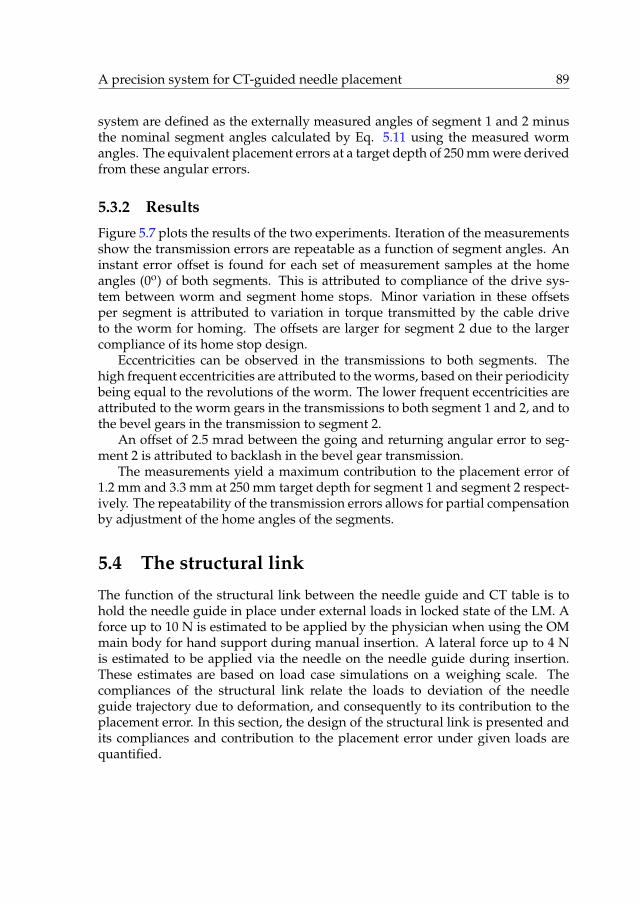
A precision system for CT-guided needle placement 89
system are defined as the externally measured angles of segment 1 and 2 minusthe nominal segment angles calculated by Eq. 5.11 using the measured wormangles. The equivalent placement errors at a target depth of 250 mm were derivedfrom these angular errors.
5.3.2 Results
Figure 5.7 plots the results of the two experiments. Iteration of the measurementsshow the transmission errors are repeatable as a function of segment angles. Aninstant error offset is found for each set of measurement samples at the homeangles (0o) of both segments. This is attributed to compliance of the drive sys-tem between worm and segment home stops. Minor variation in these offsetsper segment is attributed to variation in torque transmitted by the cable driveto the worm for homing. The offsets are larger for segment 2 due to the largercompliance of its home stop design.
Eccentricities can be observed in the transmissions to both segments. Thehigh frequent eccentricities are attributed to the worms, based on their periodicitybeing equal to the revolutions of the worm. The lower frequent eccentricities areattributed to the worm gears in the transmissions to both segment 1 and 2, and tothe bevel gears in the transmission to segment 2.
An offset of 2.5 mrad between the going and returning angular error to seg-ment 2 is attributed to backlash in the bevel gear transmission.
The measurements yield a maximum contribution to the placement error of1.2 mm and 3.3 mm at 250 mm target depth for segment 1 and segment 2 respect-ively. The repeatability of the transmission errors allows for partial compensationby adjustment of the home angles of the segments.
5.4 The structural link
The function of the structural link between the needle guide and CT table is tohold the needle guide in place under external loads in locked state of the LM. Aforce up to 10 N is estimated to be applied by the physician when using the OMmain body for hand support during manual insertion. A lateral force up to 4 Nis estimated to be applied via the needle on the needle guide during insertion.These estimates are based on load case simulations on a weighing scale. Thecompliances of the structural link relate the loads to deviation of the needleguide trajectory due to deformation, and consequently to its contribution to theplacement error. In this section, the design of the structural link is presented andits compliances and contribution to the placement error under given loads arequantified.
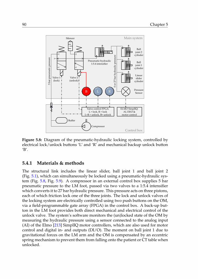
90 Chapter 5
Control box
Main system
Pneumatic-hydraulic1:5.4 intensifier
L R
5 b
ar p
neu
mat
ic p
ress
ure
0 o
r 27
bar
hy
dra
uli
c p
ress
ure
Compressor
Valve control FPGA:L = lock, R = lock
L+R = unlock, B= unlock
Valve 1(lock)
Valve 2(unlock)
Balljoint 1
cylinder
Balljoint 2
cylinder
Linearslider
cylinder
B
Silencer
PressureSensor
Buffer
ELMO SimplIQ:AI, DI/O &
motor control
Figure 5.8: Diagram of the pneumatic-hydraulic locking system, controlled byelectrical lock/unlock buttons ‘L’ and ‘R’ and mechanical backup unlock button‘B’.
5.4.1 Materials & methods
The structural link includes the linear slider, ball joint 1 and ball joint 2(Fig. 5.1), which can simultaneously be locked using a pneumatic-hydraulic sys-tem (Fig. 5.8, Fig. 5.9). A compressor in an external control box supplies 5 barpneumatic pressure to the LM foot, passed via two valves to a 1:5.4 intensifierwhich converts it to 27 bar hydraulic pressure. This pressure acts on three pistons,each of which friction lock one of the three joints. The lock and unlock valves ofthe locking system are electrically controlled using two push buttons on the OM,via a field-programmable gate array (FPGA) in the control box. A back-up but-ton in the LM foot provides both direct mechanical and electrical control of theunlock valve. The system’s software monitors the (un)locked state of the OM bymeasuring the hydraulic pressure using a sensor connected to the analog input(AI) of the Elmo [213] SimplIQ motor controllers, which are also used for motorcontrol and digital in- and outputs (DI/O). The moment on ball joint 1 due togravitational forces on the LM arm and the OM is compensated by an eccentricspring mechanism to prevent them from falling onto the patient or CT table whenunlocked.

A precision system for CT-guided needle placement 91
X-r
ay t
ran
spar
ent
vo
lum
e
Bal
l jo
int
2 h
yd
rau
lic
cyli
nd
erB
all
join
t 1
spri
ng
mec
han
ism
Si 3
N4
bal
l b
eari
ng
s
Bo
rosi
lica
te g
lass
ax
le
Al 2
O3
seg
men
t 2
Gla
ss f
ibre
LM
arm
& b
all
join
t 2
Bal
l jo
int
1 h
yd
rau
lic
cyli
nd
er
Sli
der
hy
dra
uli
c cy
lin
der
Alu
min
ium
LM
fo
ot
& b
all
join
t 1
Hy
dra
uli
c p
ress
ure
sen
sor
Pn
eum
atic
val
ves
Rig
id G
F O
M m
ain
bo
dy
& s
egm
ent
1
Figure 5.9: Cross section of the system with labelled components of the lockingsystem and materials forming the structural link.

92 Chapter 5
The compliance of the structural link is constituted by its geometry and themechanical properties of its materials. The geometry was designed based onconstraints on the available space between patient and CT scanner bore andrequirements on the range and freedom of movement of the OM. In additionto mechanical properties, considerations for material selection are radiolucency,sterilizability, manufacturability and production costs. Figure 5.9 indicates thematerials of the main components that form the structural link, which includealuminium, aluminium oxide, glass fibre reinforced epoxy and SLS 3D printedRigid GF.
Performance analysis
The compliances were determined by measuring the deflection of the needleguide under the gravitational force of an external mass. The pose of the struc-tural link changes its geometry and consequently its compliance. Two worst caseposes were therefore considered, each with a specific corresponding load case.
Firstly, the OM was locked in horizontal position (Fig. 5.10a). A vertical forceFMB
y was applied to the main body (MB) of the OM by external mass m1 �0.999 kgvia a string. Subscript y in FMB
y indicates the directional component of the force,and superscript MB indicates the position where it is applied. A tool holdingtwo spheres was mounted in the needle guide (NG) to determine its deflection.The spheres are a distance l � 80 mm apart, coincide with the axial trajectoryof the needle guide and one sphere coincides with the RCM. Deflections dx1,dx2 and dy1 of the spheres due to load application were measured using a Käfer[215] dial gauge with 0.01 mm resolution. The compliances CMB:NG
y,y and CMB:NGy,ϕ
relating force FMBy to the vertical deflection dyNG and angular deflection dϕNG of
the needle guide respectively are defined and calculated as follows:
CMB:NGy,x �
BxNG
BFMBy
�dx1
m1g, (5.12a)
CMB:NGy,y �
ByNG
BFMBy
�dy1
m1g, (5.12b)
CMB:NGy,ϕ �
BϕNG
BFMBy
�pdx2 � dx1q{l
m1g, (5.12c)
with g the gravitational acceleration. Subscripts py, yq and py, ϕq here indicate(directional component of the applied force, directional component of the deflection). Su-perscript pMB:NGq indicates (position of the applied load to position of the deflection).The placement error eMB at target depth L due to force FMB
y is calculated as thesum of orthogonal contributions due to vertical, horizontal and angular deflec-tions of the needle guide (Fig. 5.10a):

A precision system for CT-guided needle placement 93
Dial gauge
Mass m1
dy1
dx1
FMBy
dx2
dx1
dy1
eMB
L
dϕNG
dldx2
(a) Measurement of deflections dx1, dx2 and dy1 under load FMBy by
mass m1 on the main body (MB) of the OM, and corresponding de-flection diagram.
Dial gauge
Mass m2
dy3FS2ydy2
dy3
dy2
eS2
L
dϕNG
dl
(b) Measurement of deflections dy2 and dy3 under load FS2y by mass
m2 on segment 2 (S2), and corresponding deflection diagram.
Figure 5.10: Experiment setups to determine the compliances of the structurallink from needle guide to table.
eMB ��pdϕNGL � dx1q
2 � pdyNGq2�0.5
���pCMB:NG
y,ϕ L � CMB:NGy,x qFMB
y�2
� pCMB:NGy,y FMB
y q20.5
.
(5.13)

94 Chapter 5
Secondly, the OM was locked in vertical position (Fig. 5.10b). A vertical forceFS2
y was applied at the needle guide on segment 2 (S2) by external mass m2 �0.399kg via a string. Vertical deflections dy2 and dy3 of the spheres were subsequentlymeasured using the dial gauge. The horizontal deflections were estimated tobe negligible and ignored. The compliances CS2:NG
y,y and CS2y,ϕ relating force FS2
y
to the vertical deflection dyNG and angular deflection dϕNG of the needle guiderespectively are defined and calculated as follows:
CS2:NGy,y �
ByNG
BFS2y
�dy2
m2g, (5.14a)
CS2:NGy,ϕ �
BϕNG
BFS2y
�pdy3 � dy2q{l
m2g. (5.14b)
The placement error eS2 at target depth L due to force FS2y is calculated as the sum
of the (opposite) contributions of vertical and angular deflections of the needleguide (Fig. 5.10b):
eS2 � ‖dϕNGL � dyNG‖� ‖pCS2:NG
y,ϕ L � CS2:NGy,y qFS2
y ‖ .(5.15)
5.4.2 Results
The measured deflections in the two experiment setups and compliances calcu-lated using Eq. 5.12 and 5.14 are:
dx1 � 0.02 mm CMB:NGy,x � 2 � 10�3 mm/N
dx2 � 0.07 mm CMB:NGy,y � 31 � 10�3 mm/N
dy1 � 0.30 mm CMB:NGy,ϕ � 0.064 � 10�3 rad/N
dy2 � 0.14 mm CS2:NGy,y � 36 � 10�3 mm/N
dy3 � 0.32 mm CS2:NGy,ϕ � 0.57 � 10�3 rad/N
For estimated forces FMBy � 10 N and FS2
y � 4 N and a target depth of L � 250mm, contributions to the placement error of eMB � 0.34 mm and eS2 � 0.43mm are calculated respectively using Eq. 5.13 and 5.15 for the two poses withcorresponding load cases.

A precision system for CT-guided needle placement 95
5.5 The overall system
In this section, the placement error of the overall system integrated with a CTscanner is quantified by needle placement at targets in air. The home angles ofsegment 1 and 2 were adjusted in this experiment by fixed values of 2.7 and-7.3 mrad respectively to compensate for the transmission errors determined insection 5.3.
5.5.1 Materials & methods
The system was mounted via an aluminium frame onto the table of a Siemens [35]Somatom Force CT scanner (Fig. 5.11a). The OM was locked in a pose wheretargets within the 90o conical action range of the needle guide on the 2-DOFsaiming mechanism and up to 250 mm depth from the RCM could be reachedwithout interference with the CT gantry or table. The target for the needle tipwas the centre of an external Ø20 mm spherical aluminium oxide fiducial markerat the end of a PVC rod. The rod was mounted in an aluminium holder, whichcould freely be placed and fixed to the CT table via the aluminium frame.
The volume containing the OM and the target was CT scanned using a scan-ning protocol for the liver, a pixel spacing of 0.98�0.98 mm and an image spacingof 1.5 mm (Fig. 5.11b). The centre coordinates of the fiducial markers incorpor-ated in the OM and the target fiducial marker were determined by processing ofthe CT images, as explained in section 5.2. Registration was performed and thetarget coordinates were precisely defined by the centre point of the target fiducialmarker. The angles of the needle guide to align with the target and the insertiondepth were calculated. The needle guide was automatically aimed accordingly.The PVC rod holding target fiducial marker was replaced by an aluminium rodwith a conical end, providing a point reference to the former centre position ofthe target fiducial marker. A 300 mm long Ø2 mm solid steel needle with centretip was placed in the needle guide at the calculated depth (Fig. 5.12c) and fixedby the needle clip. The placement error was measured using a calliper as theEuclidean distance between needle tip and cone apex.
Ten target positions were approached, at depths of 100 and 250 mm, and atthe centre and four quadrants of an 80o cone (Fig. 5.12d). To prepare a target at adesired position, the needle guide was first set to the appropriate angles and theneedle was placed and fixed in the needle guide at the appropriate depth. Thealuminium rod with conical end was mounted in the holder, which was placedand fixed such that the cone apex coincides with the needle tip. The needle wasthen removed and the aluminium rod was substituted by the PVC rod holdingthe fiducial marker as a target.

96 Chapter 5
(a) The system is installed on the CT table and the OM is locked. Thecentre of a fiducial marker on a PVC rod serves as a target.
Pix
el
va
lue [
HU
]
−1024
0
3071
(b) 3D CT image of the OM and target fiducial marker for OM-to-CTregistration and definition of the target coordinates.
Figure 5.11: Determining the placement error of the overall system.
5.5.2 Results
Figure 5.12d indicates the measured placement errors for the 10 target positions.A mean placement error of 1.0�0.25 mm with a maximum of 1.4 mm is found at100 mm target depth, and a mean of 2.6�0.7 mm with a maximum of 3.5 mm at250 mm depth.

A precision system for CT-guided needle placement 97
(c) The target fiducial marker is replaced by a rod with a conical end,to measure the placement error after needle placement.
0.8 mm 0.8 mm
1.1 mm1.1 mm1.4 mm
1.6 mm
3.5 mm
2.5 mm
2.8 mm
2.6 mm
100 mm depth
250 mm depth
RCM
(d) Illustration of 10 target positions at 100 and 250 mm depth fromthe RCM and corresponding placement errors.
Figure 5.11: Determining the placement error of the overall system – continued.
5.6 Discussion
The technical design of a novel system for CT-guided needle placement has beenpresented and its performance in terms of placement error has been analysed.Table 5.1 provides an overview of the contribution of the three subsystems andthe overall system for convenience.
The presented registration system relies on the acquisition of a set of parallelimages covering the fiducial markers incorporated in the OM. Image segmenta-tion by pixel value thresholding is employed to find the markers by image seg-

98 Chapter 5
Table 5.1: Overview of placement error contributions at 250 mm target depth.
(Sub)system Placement error
mm
Registration system (TRE) 0.81�0.34
Drive system (segment 1) 1.2
Drive system (segment 2) 3.3
Structural link (OM main body loaded, 10 N) 0.34
Structural link (segment 2 loaded, 4 N) 0.43
Overall system (unloaded) 2.6�0.7a
a Home angles of segments 1 and 2 adjusted by 2.7 and -7.3 mrad to compensate for transmissionerrors.
mentation, followed by a numerical method to determine the position and orient-ation of the OM corresponding to a minimum of the sum of the squared fiducialregistration errors. The registration system functions for any position and orient-ation of the OM within the field of view of CT scanner and no other calibrationbetween system and CT scanner is required. The performance of the registrationsystem has been analysed using a dummy frame holding four fiducial markersfor registration and a fifth marker serving as a target. The successfulness andcontribution to the placement error of the registration system depend on the pixelvalue threshold level. For successful segmentation of the Ø20 mm aluminium ox-ide markers and a low FRE and TRE, a pixel value threshold level between 3200and 3700 is appropriate.
Automation of the 2-DOFs mechanism to aim the needle guide has been real-ized using remote actuation via endless cables to preserve sufficient X-ray trans-parency. Fibre optic encoders on the worms are used for angular feedback. Thetransmission of the drive system from worms to segments has the largest contri-bution to the placement error amongst the three subsystems, attributed to homestop compliance, gear eccentricity and backlash. Home stop compliances in com-bination with variable cable drive torques yield variable home angle offsets. Geareccentricity and average home angle offsets can partially be compensated forusing the measured transmission errors. The performance can be improved byredesign of the home stops using X-ray transparent alternatives which do notrely on motor torque thresholding, such as carbon electrical or fibre optical limitswitches.
The structural link between needle guide and CT table is composed of alu-minium, glass fibre reinforced composites and ceramics to reduce its compliance.The placement error due to deformation of the structural link was determined for

A precision system for CT-guided needle placement 99
two poses and realistic load cases of the OM and the needle guide respectively.The physician should be instructed to avoid applying external loads in order tominimize deflection of the needle guide and the corresponding contribution tothe placement error.
The performance of the overall system in terms of placement error in air doesnot exceed the ¤5 mm error specified as a clinical user requirement for needleplacement in tissue, up to an extreme target depth of 250 mm. Additional contrib-utors to the needle tip placement error beyond control of the system are needledeflection and tissue displacement. Given the precise alignment of the needleguide with a target, needles with a symmetrical tip are recommended to followa straight trajectory. To minimize deviation of the target tissue from the spe-cified static target coordinates due to respiration, CT imaging and needle inser-tion should be performed during a breath-hold in the same respiratory phase,conform current clinical practise. Phantom and patient studies are required tovalidate the full performance of the system.

100 Chapter 5

CHAPTER 6
Validation of a system for CT-guided needleplacement in the thorax and abdomen - a phantom
study
Maarten M. Arnolli, Wout J. Heerink, Jan Pieter Pennings,Dannis M. Brouwer, Ivo A.M.J. Broeders and Koert P. de Jong
In preparation for submission to Radiology, Radiological Society of North America.
Abstract
Background A system for CT-guided needle placement was developed whichprovides precise alignment of a needle guide to reach a target in a single manualinsertion. The objective of this work is to validate the system by a performancecomparison of its guided method and the conventional freehand method.
Methods Two experienced physicians employed both methods to reach targetsat 120 mm depth via in-plane and 30o out-of-plane paths in a gelatin phantom,with a goal to reach ¤5 mm Euclidean error in ¤5 needle manipulations.
Results Guided versus freehand for in-/out-of-plane achieved 100.0/100.0vs. 83.3/33.3% successfulness (p=0.478/p<0.001), 1.0�0.0/1.0�0.0 vs.3.4�1.2/4.8�0.4 needle manipulations (p<0.001/p<0.001), 2.6�0.9/2.7�0.9vs. 4.8�2.5/14.4�12.5 mm Euclidean error (p=0.002/p<0.001), 1.0�0.6/0.8�0.6vs. 2.0�1.5/1.7�0.4 Gy�mm total dose-length-product (p=0.043/p=0.001)and 7:25�1:34/7:40�1:33 vs. 10:45�3:48/21:15�4:50 minutes placement time(p=0.013/p<0.001).
Conclusions The system consistently enables user-independent successfulneedle placement in a single insertion, with smaller placement error, lower ra-diation dose and shorter placement time.
101

102 Chapter 6
6.1 Introduction
Minimally invasive biopsy and ablation of tumours in the abdomen and thoraxare typically performed via a needle which is inserted percutaneously (‘throughthe skin’) using image-guidance to reach the target tissue. X-ray spiral CT-guidedpercutaneous needle placement is normally performed freehand. The perform-ance of this method is user-dependent and multiple iterations of needle place-ment and CT scanning for placement verification are generally required beforesatisfactory placement is achieved. Each iteration increases tissue damage withaccompanied risks, patient X-ray exposure, procedure time and costs.
A variety of systems has been developed over the past decades to improvethe procedure of CT-guided needle placement, ranging from simple passive aidsto fully automated robots [72]. Exemplary systems that surpass the experimentalstage include the laser guidance system Amedo LNS [216], the navigation sys-tem CAScination CAS-One [217], and the systems Perfint MAXIO [218] and iSYSMedizintechnik iSYS1 [219] which provide physical needle guidance. Despite thevarious attempted strategies and often technically sound solutions, widespreadclinical adoption of any system is lacking. A novel system for CT-guided percu-taneous needle placement in the thorax and abdomen, the DEMCON NPS, wasdeveloped to enable user-independent precise needle placement in a single in-sertion, and designed with a focus on clinical acceptability, applicability and us-ability (Fig. 6.1). The strategy of the system is to provide precise alignment ofa needle guide with a user-specified target for physical support during a singlemanual needle insertion.
A pre-clinical phantom study is presented with the objective to validate thesystem, by ex vivo comparison of the performances of guided and freehandneedle placement. The simulated use case is CT-guided percutaneous needleplacement for microwave ablation (MWA) of liver tumours.
6.2 Materials & methods
This section first discusses the freehand and guided needle placement methods,followed by the experiment setup of the phantom study.
6.2.1 Procedure & freehand needle placement
As a starting point of the MWA procedure, the patient is accommodated on theCT table, general anaesthesia and medical ventilation are applied and a sterileworkspace is created. An initial set of exploratory CT images of the relevantanatomical area is acquired and reviewed on a DICOM image viewer to find thetumour and plan a suited needle path. A radiocontrast agent may be admin-istered to enhance tumour visibility. A sheet of radiopaque grid-lines is placedon the patient’s skin around the estimated location of the needle entry point and

Validation of a system for CT-guided needle placement 103
Figure 6.1: Prototype of the validated system for CT-guided needle placementduring experimental validation.
a second CT scan is performed. The entry point is commonly chosen such that itcoincides with one of the grid-lines. The patient table is translated such that theplane of a laser incorporated in the CT gantry coincides with the image positionof the planned entry point. The crossing of the laser plane with the selected gridline marks the entry point on the patient’s skin.
The next step is to estimate the path angles from entry point to target on theavailable CT images and insert the needle accordingly. An iterative method offreehand needle insertion and subsequent CT scanning for verification is em-ployed. A lightweight hypodermic needle may be superficially inserted as afirst estimate. The required insertion depth is determined on the DICOM im-age viewer and measured with respect to the skin using linear markings on theneedle. All scanning sequences and insertions are performed under paused res-piration in the same state to minimize deviations of the tumour position. Abla-tion is started once the needle tip has successfully reached the target. Freehandneedle placement is particularly challenging for paths out-of-plane, i.e. obliqueto the transversal CT image, which are common to reach tumours in the upperpart of the liver without puncturing the lung.

104 Chapter 6
6.2.2 Novel system & guided needle placement
The DEMCON NPS (Fig. 6.1) incorporates a needle guide which is aimed by a 2degrees of freedom (2-DOFs) actuated remote centre of motion (RCM) mechan-ism, referred to as the orientation module (OM). The OM includes handlebars andcan freely be placed around the patient and locked with respect to the patienttable via a 6-DOFs linkage, referred to as the locking module (LM).
The system is installed on the patient table prior to the procedure. A first CTscan of the relevant part of the anatomy is performed for initial path planningand entry point retrieval, identically to the freehand method (Fig. 6.2a). The OMis manually placed by the physician to coincide the RCM with the entry pointand push-button locked to the table by the LM (Fig. 6.2b). The RCM is hereto in-dicated by a pointer placed in the needle guide. A second CT scan is performedof the relevant anatomy together with the OM (Fig. 6.2c), and the images areloaded into the system’s graphical user interface (GUI). Four fiducial markers areincorporated in the OM, which serve as references for automated OM-to-CT re-gistration [181]. The GUI includes a DICOM viewer used for target specification.The planned path from RCM to target is superimposed on the images for review.The required angles of the RCM mechanism to align the needle guide with thetrajectory from RCM to target are automatically calculated, together with the cor-responding insertion depth.
Upon approval of the planned path in the GUI, a button on the LM becomesactive. When the button is pushed, the RCM mechanism automatically rotatesto the required angles, aligning the needle guide with the target (Fig. 6.2d). Ablue light-emitting diode (LED) on the LM turns on to indicate aiming is ready.The needle is now inserted manually in a single action through the needle guideto the specified depth (Fig. 6.2e). A third CT scan is performed for placementverification (Fig. 6.2e).
6.2.3 Experiment setup
Both needle placement methods were employed to approach targets in a statichomogeneous gelatin phantom as an artificial substitute to the human abdom-inal anatomy, under controlled conditions for performance comparison. Two setsof 6 paths each were prepared by predefined target positions and correspond-ing entry points. The sets are distinguished by in-plane and 30o out-of-planepaths. The nominal insertion depth from entry point to target for all paths inboth sets was maintained at 120 mm. The used needle was a 20 cm long, 13 gauge(Ø2.4 mm) Covidien [206] EMprint MWA needle with a 3-facet diamond shapetip. Two physicians were involved as operators in the experiment. Both operat-ors routinely perform freehand CT-guided percutaneous needle placement andhave at least six years of experience with this type of procedure. Each operatorattempted each path by each method once in random order, yielding a total of2�12�2�48 attempted paths.

Validation of a system for CT-guided needle placement 105
(a) The system installed on the patient table,awaiting initial path planning and entry pointretrieval.
(b) Manual placement of the OM such that theRCM coincides with the entry point and push-button controllled locking to the patient table bythe LM.
(c) CT scanning of patient and OM for OM-to-CT registration using four fiducial markers andfor target specification.
(d) Automated aiming of the needle guide by theRCM mechanism.
(e) Manual needle insertion through the needleguide to specified depth.
(f) CT scanning for placement verification.
Figure 6.2: Illustrations of the system’s guided method for needle placement.

106 Chapter 6
(a) Structural frame with targets on skewers, in-side the box for moulding.
(b) Structural frame and cast gelatin after ejec-tion from the mould box.
Figure 6.3: Abdominal phantom construction.
Phantom construction
The phantom incorporates a frame cut from a plastic box (345�230�160 mm) forstructural integrity (Fig. 6.3). Glued to the inside of the frame is a 5 mm PMMAplate with a grid of holes, in which Ø2 mm wooden skewers are inserted. Clayspheres mixed with carbonyl iron powder for image contrast (10:100 powder toclay weight ratio) are placed at the tip of the skewers as targets. The frame fitsinto a second plastic box with a rounded bottom, which serves as a mould to castthe gelatin (15:100 gelatin powder to water weight ratio) (Fig. 6.3a). Once thegelatin has set, it is ejected with the frame from the outer box (Fig. 6.3b). Therounded gelatin surface represents the side of the abdomen, and is covered bysynthetic chamois leather to block visibility of the targets. The position of theholes and length of the skewers position the targets such that the intended in-plane and 30o out-of-plane paths of 120 mm insertion depth are established fromthe corresponding entry points. The prepared paths are sufficiently far apart toavoid intersection of the needle with present tracts of previously attempted paths.A flexible plastic sheet with holes is used as a template to mark the predefinedentry points on the chamois leather. Dots of the same clay/carbonyl iron powdermixture are placed on the entry points for indication on the images of the initialexploratory CT scan. The frame of the phantom was bolted onto a plexiglas tray,which was fixated via aluminium frames to the patient table (Fig. 6.1). The gelatinwas recast after all prepared paths were attempted, such that repetition by analtered method or operator always started in intact gelatin.

Validation of a system for CT-guided needle placement 107
System & CT scanner integration
The system was integrated with a Siemens Somatom Force CT scanner. Its lin-ear rail was mounted on a provisional aluminium frame fixed to the patient table(Fig. 6.1). Scan and reconstruction protocols clinically used for minimally invas-ive tumour ablation were applied, with a constant 1.0 mm slice thickness. Uponimage reconstruction, DICOM files were automatically and instantly transferredto the computer of the needle placement system using K-PACS [220] server soft-ware.
Calibration of the needle placement system
The relative positions of the fiducial markers and the functional geometry of theRCM mechanism were measured using a FARO [212] GagePlus measuring armwith a specified volumetric length measuring uncertainty of 5 µm. The 2-DOFsRCM mechanism relies on incremental rotatory encoders for positional feed-back. A homing procedure is therefore performed, in which the RCM mechanismmoves to mechanical end stops. The corresponding home angles were calibratedprior to the experiment by repeated targeting at Ø2 mm lead balls taped to thepatient table at ¥250 mm from the RCM, and updating the segment home anglesto align the tip of a Ø2.4 mm steel needle with the balls.
Experiment execution
Figure 6.4 shows a flowchart of the two methods as followed in the experiment.At the defined start of both methods, an initial exploratory set of CT images ofthe phantom is available, on which the predefined targets and correspondingentry points are clearly visible. Also, the entry points are marked on the chamoisleather.
Needle placement was considered successful once the Euclidean (’point-to-point’) error between needle tip and target was ¤5 mm, which is deemed suf-ficient for the intended clinical application. A maximum of 5 manipulations ofthe MWA needle was permitted for the iterative freehand method. Placement ofthe auxiliary hypodermic needle in the freehand method was optional and couldfreely be skipped according to the operator’s own judgement. Only 1 insertionwas permitted for the guided method, in accordance with the intended use of theneedle placement system. OM-to-CT registration is obstructed when the imagedvolume does not encompass all four fiducial markers. In this case, either theplacement of the OM, the table height, the field of view and/or the scan rangewere adjusted and a new scan was performed.
Measures of performance are the percentage of successful needle placements,the number of MWA needle insertions, the geometric placement errors, the num-ber of CT scans, radiation dose, and procedure time from skin incision (in case of

108 Chapter 6
Guided
Freehand
Start
Create skin incision
(CT scan)
Insert/adjust MWA needle
CT scan
(Re)place OM and push button to activate locking
CT scan & transferDICOM files
Load DICOM files in GUI
Create skin incision
CT scan
No
No
Yes
Euc. error <5mm or# needle manipulations>5?
Specify target in GUI
Registration successful?
Yes
Image segmentation andOM-to-CT registration
Lock the OM
Calculate RCM mechanism angles & insertion depth
Approve path in GUI & push button to aim needle guide
Aim needle guide &turn on blue LED
Finish
(Insert hypodermic needle)
Insert MWA needle
Review needle placement
(Review needle trajectory)
Figure 6.4: Flowchart of the freehand and guided needle placement methods.
the freehand method) or OM placement (in case of the guided method) to last CTscan.
Prior to the experiment execution, the functioning and use of the needleplacement system, both placement methods and the experiment setup were thor-

Validation of a system for CT-guided needle placement 109
xT
eL
ePeE
Needle xNxE
eA
Figure 6.5: Illustration of the geometrical definition of the Euclidean (eE), lateral(eL), axial (eA) and projected error (eP).
oughly explained to the operators. Each operator performed three needle place-ments by each method as part of the preparation. Data from these trials are ex-cluded from the results.
Data acquisition & processing
The number of MWA needle manipulations were counted and the times of skinincisions, OM placements and CT scans were monitored on a digital clock. AllDICOM files containing the reconstructed CT images and metadata were storedtogether with the CT coordinates of the target (xT), skin entry point (xE) andneedle tip (xN) after each insertion. Four errors are geometrically defined by thesecoordinates (Fig. 6.5). The Euclidean error (the point-to-point distance betweenneedle tip and target):
eE � ‖xN � xT‖ , (6.1)
the lateral error (the maximum distance between needle tip and planned path):
eL �‖pxN � xEq � pxN � xTq‖
‖xT � xE‖, (6.2)
the axial error (the distance along the needle from its tip to the point closest to thetarget):
eA � ‖ pxT � xEq � pxN � xEq
‖xN � xE‖� ‖xN � xE‖‖ , (6.3)
and the projected error (the minimum distance between target and needle path):
eP �‖pxT � xEq � pxT � xNq‖
‖xN � xE‖. (6.4)
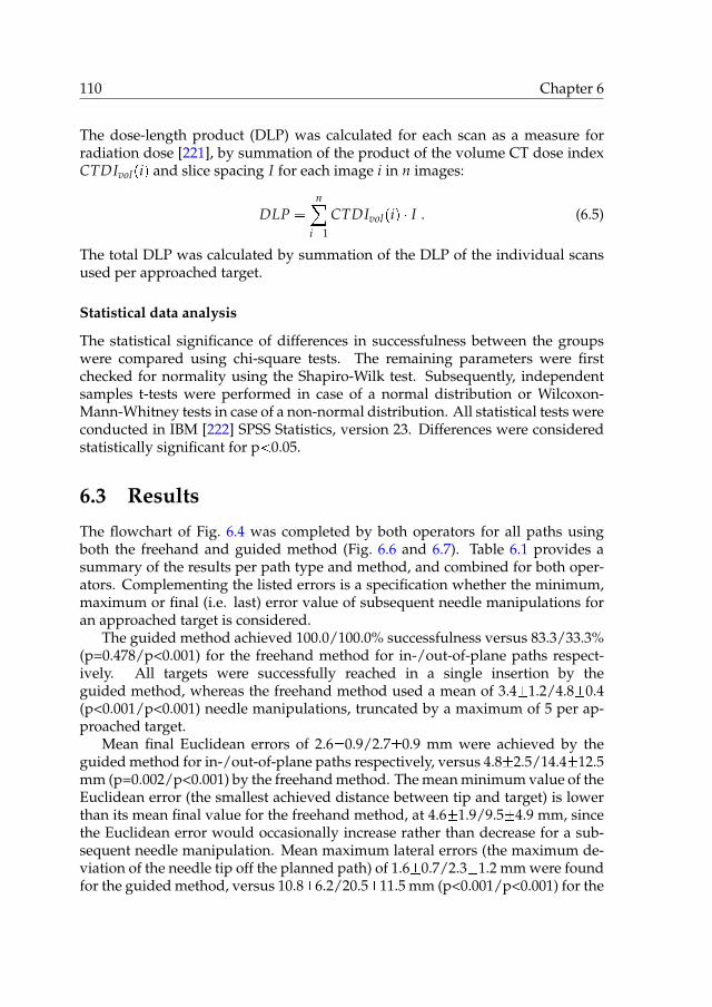
110 Chapter 6
The dose-length product (DLP) was calculated for each scan as a measure forradiation dose [221], by summation of the product of the volume CT dose indexCTDIvolpiq and slice spacing I for each image i in n images:
DLP �n
i�1
CTDIvolpiq � I . (6.5)
The total DLP was calculated by summation of the DLP of the individual scansused per approached target.
Statistical data analysis
The statistical significance of differences in successfulness between the groupswere compared using chi-square tests. The remaining parameters were firstchecked for normality using the Shapiro-Wilk test. Subsequently, independentsamples t-tests were performed in case of a normal distribution or Wilcoxon-Mann-Whitney tests in case of a non-normal distribution. All statistical tests wereconducted in IBM [222] SPSS Statistics, version 23. Differences were consideredstatistically significant for p 0.05.
6.3 Results
The flowchart of Fig. 6.4 was completed by both operators for all paths usingboth the freehand and guided method (Fig. 6.6 and 6.7). Table 6.1 provides asummary of the results per path type and method, and combined for both oper-ators. Complementing the listed errors is a specification whether the minimum,maximum or final (i.e. last) error value of subsequent needle manipulations foran approached target is considered.
The guided method achieved 100.0/100.0% successfulness versus 83.3/33.3%(p=0.478/p<0.001) for the freehand method for in-/out-of-plane paths respect-ively. All targets were successfully reached in a single insertion by theguided method, whereas the freehand method used a mean of 3.4�1.2/4.8�0.4(p<0.001/p<0.001) needle manipulations, truncated by a maximum of 5 per ap-proached target.
Mean final Euclidean errors of 2.6�0.9/2.7�0.9 mm were achieved by theguided method for in-/out-of-plane paths respectively, versus 4.8�2.5/14.4�12.5mm (p=0.002/p<0.001) by the freehand method. The mean minimum value of theEuclidean error (the smallest achieved distance between tip and target) is lowerthan its mean final value for the freehand method, at 4.6�1.9/9.5�4.9 mm, sincethe Euclidean error would occasionally increase rather than decrease for a sub-sequent needle manipulation. Mean maximum lateral errors (the maximum de-viation of the needle tip off the planned path) of 1.6�0.7/2.3�1.2 mm were foundfor the guided method, versus 10.8�6.2/20.5�11.5 mm (p<0.001/p<0.001) for the

Validation of a system for CT-guided needle placement 111
(a) Freehand manual needle insertion.
Pix
el
va
lue [
HU
]
−1024
0
3071
(b) 3D CT image of 6 superimposed scans for verification of sub-sequent attempts to reach the outlined target.
Figure 6.6: Experiment execution using the freehand method.
freehand method. No major difference per method was found for the final axialerror for in-plane paths: 1.7�1.2 mm for guided versus 1.7�1.8 mm (p=0.564)for freehand. For out-of-plane paths, the final axial error of the guided methodwas slightly better than freehand, at 1.0�0.7 mm versus 2.9�2.1 mm (p=0.011)respectively. Final projected errors of 1.6�0.7/2.3�1.2 mm were achieved by theguided method for in-/out-of-plane paths respectively, versus 4.3�2.1/13.9�12.5mm (p<0.001/p<0.001) by the freehand method. The iterative character and user-dependency of the freehand method is illustrated by plotting the lateral errorversus insertion depth (Fig. 6.8) and the projected error versus the needle inser-

112 Chapter 6
(a) Guided manual needle insertion after automatic aiming.
Pix
el
va
lue [
HU
]
−1024
0
3071
(b) 3D CT image for verification, confirming successful needle place-ment.
Figure 6.7: Experiment execution using the guided method.
tion number (Fig. 6.9). Initial estimates of the needle direction deviate up to 35/50mm off target for in-/out-of-plane paths. The projected errors tend to improvewith each subsequent manipulation for in-plane paths. Less improvement and alarger difference between the two operators was found for out-of-plane paths.

Validation of a system for CT-guided needle placement 113
Tabl
e6.
1:R
esul
tssu
mm
ary ,
com
bine
dfo
rbo
thop
erat
ors.
IP=
in-p
lane
path
s,O
OP
=ou
t-of
-pla
nepa
ths.
Para
met
erU
nits
val.
val.
p-va
l.va
l.va
l.p-
val.
val.
Path
type
[-]
IPIP
OO
PO
OP
IP+O
OP
Met
hod
[-]
Free
hand
Gui
ded
Free
hand
Gui
ded
Gui
ded
#Pa
ths
[-]
1212
1212
24
Inse
rtio
nde
pth
[mm
]12
3.4�
5.2
122.
7�4.
712
0.5�
3.0
119.
9�3.
712
1.3�
4.4
Succ
essf
ulne
ss[%
]83
.310
0.0
0.47
8a33
.310
0.0
<0.0
01a
100.
0
#M
WA
need
lem
anip
ulat
ions
[-]
3.4�
1.2
1.0�
0.0
<0.0
01b
4.8�
0.4
1.0�
0.0
<0.0
01b
1.0�
0.0
Eucl
idea
ner
ror
(fina
l)[m
m]
4.8�
2.5
2.6�
0.9
0.00
2b14
.4�
12.5
2.7�
0.9
<0.0
01b
2.6�
0.9
Eucl
idia
ner
ror
(min
.)[m
m]
4.6�
1.9
2.6�
0.9
0.00
2b9.
5�4.
92.
7�0.
90.
001c
2.6�
0.9
Late
rale
rror
(max
.)[m
m]
10.8�
6.2
1.6�
0.7
<0.0
01c
20.5�
11.5
2.3�
1.2
<0.0
01c
1.9�
1.1
Axi
aler
ror
(fina
l)[m
m]
1.7�
1.8
1.7�
1.2
0.56
4b2.
9�2.
11.
0�0.
70.
011c
1.4�
1.0
Proj
ecte
der
ror
(fina
l)[m
m]
4.3�
2.1
1.6�
0.7
<0.0
01b
13.9�
12.5
2.3�
1.2
<0.0
01b
1.9�
1.1
#C
Tsc
ans
(exc
l.0-
scan
)[-
]3.
8�1.
22.
2�0.
60.
001b
5.9�
0.5
2.2�
0.4
<0.0
01b
2.2�
0.5
Tota
lDLP
(exc
l.0-
scan
)[G
y�m
m]
2.0�
1.5
1.0�
0.6
0.04
3b1.
7�0.
40.
8�0.
60.
001b
0.9�
0.6
Tim
e[m
in]
10:4
5�3:
487:
25�
1:34
0.01
3b21
:15�
4:50
7:40�
1:33
<0.0
01b
7:33�
1:32
a Chi
squa
rete
st.
b Wilc
oxon
-Man
n-W
hitn
eyte
st.
c Inde
pend
ents
ampl
est-
test
.

114 Chapter 6
0 20 40 60 80 100 120 1400
5
10
15
20
25
30
35
40
45
50
Needle insertion depth [mm]
Lat
eral
pla
cem
ent
erro
r [m
m]
Operator 1
Operator 2
(a) In-plane paths.
0 20 40 60 80 100 120 1400
5
10
15
20
25
30
35
40
45
50
Needle insertion depth [mm]L
ater
al p
lace
men
t er
ror
[mm
]
Operator 1
Operator 2
(b) Out-of-plane paths.
Figure 6.8: Lateral error versus insertion depth for the freehand method.
# Needle manipulations [−]
Pro
ject
ed
err
or
[mm
]
1 2 3 4 5 61
5
10
20
40
80
Operator 1
Operator 2
(a) In-plane paths.
# Needle manipulations [−]
Pro
ject
ed
err
or
[mm
]
1 2 3 4 5 61
5
10
20
40
80
Operator 1
Operator 2
(b) Out-of-plane paths.
Figure 6.9: Projected error versus number of needle manipulations (of the MWAneedle and the hypodermic needle if applicable) with intermediate CT-scans forthe freehand method.
The guided method required 2.2�0.6/2.2�0.4 CT scans (excluding the ini-tial 0-scan) for in-/out-of-plane paths respectively, versus 3.8�1.2/5.9�0.5(p=0.001/p<0.001) for the freehand method. OM-to-CT registration was ob-

Validation of a system for CT-guided needle placement 115
Fiducial 2
Fiducial 4
Fiducial 1
Fiducial 3
Phantom
CT table
Figure 6.10: Front view of a 3D CT image in which segmentation was obstructeddue to partial exclusion of fiducial 4 from the imaged volume.
structed in 4 cases when the imaged volume did not encompass all four fidu-cial markers (Fig. 6.10) and a new scan was required. The total DLP used bythe guided method (excluding the initial 0-scan) were 1.0�0.6/0.8�0.6 Gy�mm,versus 2.0�1.5/1.7�0.4 Gy�mm (p=0.043/p=0.001) for the freehand method.
Time from OM placement to last CT scan for the guided method measured7:25�1:34 min and 7:40�1:33 min for in- and out-of-plane paths respectively.The freehand method took significantly longer, at 10:45�3:48 min (p=0.013) and21:15�4:50 min (p<0.001) respectively from skin incision to last CT scan.
The right column of Table 6.1 lists the performance of the guided methodcombined for both in-plane and out-of plane paths: 100.0% successful needleplacement was achieved in a single insertion, with 2.6�0.9 mm Euclidean error,2.2�0.5 Gy�mm total DLP and a placement time of 7:33�1:32.
6.4 Discussion
A novel system for CT-guided percutaneous needle placement has been valid-ated by a performance comparison of its guided method and the conventionalfreehand method in a phantom study, simulating a use case of needle placement
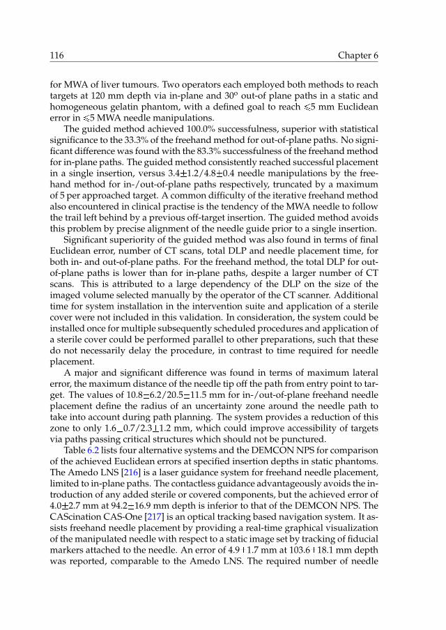
116 Chapter 6
for MWA of liver tumours. Two operators each employed both methods to reachtargets at 120 mm depth via in-plane and 30o out-of plane paths in a static andhomogeneous gelatin phantom, with a defined goal to reach ¤5 mm Euclideanerror in ¤5 MWA needle manipulations.
The guided method achieved 100.0% successfulness, superior with statisticalsignificance to the 33.3% of the freehand method for out-of-plane paths. No signi-ficant difference was found with the 83.3% successfulness of the freehand methodfor in-plane paths. The guided method consistently reached successful placementin a single insertion, versus 3.4�1.2/4.8�0.4 needle manipulations by the free-hand method for in-/out-of-plane paths respectively, truncated by a maximumof 5 per approached target. A common difficulty of the iterative freehand methodalso encountered in clinical practise is the tendency of the MWA needle to followthe trail left behind by a previous off-target insertion. The guided method avoidsthis problem by precise alignment of the needle guide prior to a single insertion.
Significant superiority of the guided method was also found in terms of finalEuclidean error, number of CT scans, total DLP and needle placement time, forboth in- and out-of-plane paths. For the freehand method, the total DLP for out-of-plane paths is lower than for in-plane paths, despite a larger number of CTscans. This is attributed to a large dependency of the DLP on the size of theimaged volume selected manually by the operator of the CT scanner. Additionaltime for system installation in the intervention suite and application of a sterilecover were not included in this validation. In consideration, the system could beinstalled once for multiple subsequently scheduled procedures and application ofa sterile cover could be performed parallel to other preparations, such that thesedo not necessarily delay the procedure, in contrast to time required for needleplacement.
A major and significant difference was found in terms of maximum lateralerror, the maximum distance of the needle tip off the path from entry point to tar-get. The values of 10.8�6.2/20.5�11.5 mm for in-/out-of-plane freehand needleplacement define the radius of an uncertainty zone around the needle path totake into account during path planning. The system provides a reduction of thiszone to only 1.6�0.7/2.3�1.2 mm, which could improve accessibility of targetsvia paths passing critical structures which should not be punctured.
Table 6.2 lists four alternative systems and the DEMCON NPS for comparisonof the achieved Euclidean errors at specified insertion depths in static phantoms.The Amedo LNS [216] is a laser guidance system for freehand needle placement,limited to in-plane paths. The contactless guidance advantageously avoids the in-troduction of any added sterile or covered components, but the achieved error of4.0�2.7 mm at 94.2�16.9 mm depth is inferior to that of the DEMCON NPS. TheCAScination CAS-One [217] is an optical tracking based navigation system. It as-sists freehand needle placement by providing a real-time graphical visualizationof the manipulated needle with respect to a static image set by tracking of fiducialmarkers attached to the needle. An error of 4.9�1.7 mm at 103.6�18.1 mm depthwas reported, comparable to the Amedo LNS. The required number of needle

Validation of a system for CT-guided needle placement 117
Table 6.2: Performance comparison of systems for CT-guided needle placement.
System Insertion depth Euclidean error
[mm] [mm]
Amedo LNS [216] 94.2�16.9 4.0�2.7
CAScination CAS-One [217] 103.6�18.1 4.9�1.7
Perfint MAXIO [218] 110�38 6.5�2.5
iSYS Medizintechnik iSYS1 [219] 92.8�14.4 2.3�0.8
DEMCON NPS 121.3�4.4 2.6�0.9
manipulations and CT scans to achieve successful placement was not reportedin [216] nor [217]. The Perfint MAXIO [218] and iSYS Medizintechnik iSYS1 [219]employ the same strategy as the DEMCON NPS to align a needle guide with auser-specified target for physical support during a single manual needle inser-tion, but use different system architectures. The Perfint MAXIO is a large floormounted system next to the CT table, providing large stroke 5-DOFs automatedplacement of a needle guide around the patient for manual insertion. The re-ported error of 6.5�2.5 mm at 110�38 mm depth is inferior to that of the DEM-CON NPS. The iSYS Medizintechnik iSYS1 is a table mounted system providing4-DOFs automated alignment of the needle guide after manual placement andlocking at the site of insertion. The reported 2.3�0.8 mm error at 92.8�14.4 mmdepth is comparable to that of the DEMCON NPS.
In conclusion, the presented system validation evidences the added value ofthe DEMCON NPS for needle placement under the controlled conditions of thephantom study and sets high expectations for its potential in clinical practise. Itendorses the system’s strategy to provide precise needle guidance to reach a tar-get in a single manual insertion, its architectural design for usability of a manu-ally placeable and push-button lockable RCM mechanism, automatic OM-to-CTregistration using fiducial markers, and automatic aiming of the needle guide,and its detail design as successfully implemented in a fully functional prototype.

118 Chapter 6

CHAPTER 7
Conclusions & outlook
7.1 Conclusions
The objective of the research described in this dissertation as formulated inchapter 1 has been:
the development of a precision system for image-guidedpercutaneous needle placement in the thorax and abdomen
In fulfilment of the objective, a clinically acceptable, widely applicable and usablesystem has been developed which enables user-independent, precise CT-guidedneedle placement in a single insertion, using a lower radiation dose and shorterplacement time (Fig. 7.1).
As a starting point of the research, an overview was created of the state ofthe art of systems for CT- and MRI-guided percutaneous needle placement in thethorax and abdomen (chapter 2). Over forty systems were identified, rangingfrom simple passive aids to fully automated robots. Despite the various attemp-ted strategies and often technically sound solutions, widespread clinical adoptionof any system is lacking. None of the systems represent a breakthrough in percu-taneous procedures on par with that of the imaging technology that made thempossible, leaving open space for innovation.
A problem analysis of the existing clinical workflow and freehand methodof CT-guided percutaneous needle placement at multiple medical centres indic-ated the prime opportunity for improvement lies in the current method of reach-ing a target by iterative needle placement and intermediate imaging for verifica-tion. Reducing the number of placement iterations needed to achieve satisfactoryplacement would be accompanied by a reduction in tissue damage, patient X-rayexposure, procedure time and costs. The strategy of a novel system for CT-guidedpercutaneous needle placement has been proposed, in which precise axial align-ment of a needle guide is provided to reach a user-specified target in a singlemanual insertion (chapter 3).
Based on user requirements, the architectural and detail design of the sys-tem has been elaborated, outlining the revised workflow and placement method.The system consists of an orientation module (OM) and a locking module (LM).
119

120 Chapter 7
Figure 7.1: The developed system in the intervention suite.
The OM contains an automated two degrees of freedom (2-DOFs) mechanism toaim a needle guide about a remote centre of motion (RCM). The LM is a pass-ive lockable 6-DOFs linkage connecting the OM to the CT table. The LM enablesa physician to manually place the OM anywhere around the patient to coincidethe RCM with the desired skin entry point and push-button lock it. The relev-ant anatomy of the patient and the OM are CT scanned to acquire a 3D image,for automatic OM-to-CT registration using fiducial markers incorporated in theOM, and for target specification and path approval in a graphical user interface.The needle guide is automatically aimed at the target, which is then reached by asingle manual needle insertion to indicated depth.
The prime consideration towards clinical acceptability of the system is to leavethe simple yet responsible task of needle insertion in the hands of the physician.Precautions to maintain a sterile workspace are implemented and the develop-ment of the system and its design are in compliance with applicable standards.A wide clinical applicability is created by the freedom of placement of the OMaround the patient, the angular range of the RCM mechanism to aim the needleguide and its range of compatible needle diameters. This enables accessibility ofmost body sites via in- or out-of-plane paths and extends the potential applicab-ility beyond the original use case of biopsy and ablation in the liver and lungs.In consideration of usability, the clinical workflow is maintained largely identical

Conclusions & outlook 121
except for the elimination of iterative steps. The challenging task of needle aim-ing is taken over by automation and rendered user-independent. OM-to-CT re-gistration and calculations of segment angles and insertion depth are handledby software, and locking and aiming are automated and push-button controlled.The substitutive user effort due to introduction of the system consists of its initialinstallation in the intervention suite, pre-procedural component sterilization andapplication of a sterile cover.
A first prototype of the system has been realized and integrated in the in-tervention suite. Its functionality has been demonstrated for 24 in- and out-of-plane punctures in a static gelatin phantom. Placement errors of 1.2�0.6 mm and2.1�0.7 mm at 79.0�8.4 mm and 156.0�6.9 mm depth respectively were achievedin a single insertion, in compliance with a clinical user requirement of ¤5 mm er-ror. Given a retrieved entry point, each target was consistently reached using afirst CT scan for OM-to-CT registration after placement of the OM and a secondCT scan for placement verification after needle insertion.
In assessment of the strategy of the novel system, three contributors to theoverall needle placement error were identified. Firstly, the alignment errors ofthe needle guide with respect to the specified target coordinates, which definedthe functional requirements that directed the elaboration of the architectural anddetail design of the novel system. Secondly, displacement of the target tissue dueto patient movement or respiration, which is effectively minimized in currentclinical practise by patient stabilization using cushioning and breath holds dur-ing image acquisition and needle insertion in the same respiratory phase. Thirdly,needle-tissue interaction, causing deflection of the needle tip and displacement ofthe target tissue. The deflections of a selection of clinically used biopsy and abla-tion needles with asymmetrical bevel and symmetrical Franseen tips have beenquantified for insertions in ex vivo porcine liver tissue (chapter 4). For a symmet-rical Franseen tip needle, a deflection off the straight trajectory of 2.0�0.6 mmat 120 mm insertion depth was measured. Larger mean deflections were meas-ured for two axi-asymmetric bevel tip needles, at 9.2�2.4 and 9.6�1.5 mm at 120mm insertion depth. The behaviour of a bevel tip needle to deflect in directionof the bevel is advantageously used in conventional freehand needle placementto adjust an off-target needle trajectory by altering its axial orientation. However,given the availability of a precisely aligned needle guide with the intention toreach a target with ¤5 mm error in a single manual insertion without interme-diate imaging, Franseen tip needles which follow a straight path are favourable,and bevel tip needles should be avoided.
The detail design of the novel system has been assessed from a technical pointof view and its performance in terms of needle placement error in air has beenanalysed (chapter 5). The contributions of three prime subsystems to the place-ment error and that of the overall system have been individually quantified. Fortargets at 250 mm depth, errors of <1.2 mm and <3.3 mm were determined for thedrive system of segment 1 and 2 respectively, 0.81�0.34 mm for the OM-to-CT re-gistration system, and 0.35 mm and 0.43 mm for two realistic load cases of the

122 Chapter 7
structural link from OM and needle guide to CT table. The placement errors inair of the overall unloaded system measured 1.0�0.25 and 2.6�0.7 mm at 100 and250 mm target depth respectively, and do not exceed the ¤5 mm error specifiedas a clinical user requirement for needle placement in tissue.
The system has been validated by a performance comparison of its guidedmethod with the conventional freehand method for CT-guided needle placement,simulating a use case of microwave ablation (MWA) of liver tumours. Two exper-ienced physicians employed both methods to reach a total of 48 targets in a staticgelatin phantom with ¤5 mm error in ¤5 needle manipulations using an MWAneedle, via predefined in-plane and 30o out-of-plane paths and an insertion depthof 120 mm (chapter 6). A successfulness of 100.0% was achieved using the guidedmethod, versus 83.3% (p=0.478) and 33.3% (p<0.001) using the freehand methodfor in-plane and out-of plane respectively. The performance of the guided methodhas been proven superior to the freehand method in every aspect with statisticalsignificance (p<0.05): successful needle placement was consistently achieved in asingle insertion, with higher accuracy and precision, fewer CT scans, lower radi-ation dose and shorter placement time, evidencing the added value of the novelsystem.
In conclusion, the key output of this research is a fully functional precisionsystem for CT-guided percutaneous needle placement in the thorax and abdo-men, ready for deployment in current clinical practise.

Conclusions & outlook 123
7.2 Outlook
Derived from its prime objective, the research described in this dissertation en-compasses several additional developments and system applications.
7.2.1 System integration with cone beam CT
System integration with cone beam CT (CBCT) has been initiated. Functionalfeasibility was demonstrated for simulated lumbar punctures in a clay spinalphantom using a Philips [85] Allura Xper cone beam CT system (Fig. 7.2), in col-laboration with Philips Healthcare [223]. Additional pockets are available in thehandlebars of the prototype (Fig. 5.2) to accommodate a more compact constel-lation of fiducial markers in consideration of the smaller diameter of the field ofview of CBCT, at the cost of a minor increase in target registration error.
(a) CBCT scanning of the system and a spinalphantom.
(b) 3D CBCT image used for OM-to-CBCT regis-tration and target specification.
(c) Manual needle insertion after automatic aim-ing of the needle guide at the specified target.
(d) 3D CBCT image after insertion for placementverification.
Figure 7.2: System integration with CBCT at the facilities of Philips Healthcare.
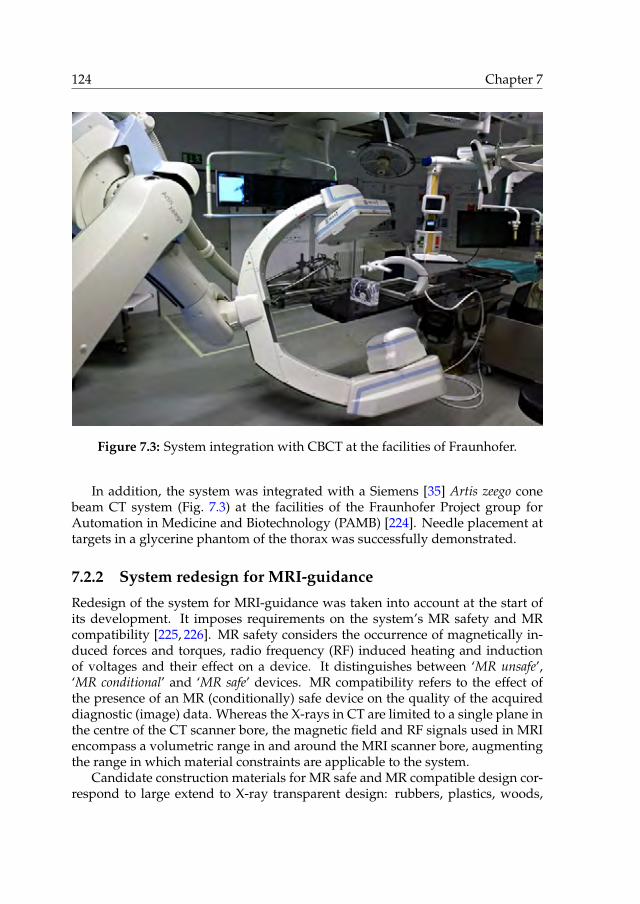
124 Chapter 7
Figure 7.3: System integration with CBCT at the facilities of Fraunhofer.
In addition, the system was integrated with a Siemens [35] Artis zeego conebeam CT system (Fig. 7.3) at the facilities of the Fraunhofer Project group forAutomation in Medicine and Biotechnology (PAMB) [224]. Needle placement attargets in a glycerine phantom of the thorax was successfully demonstrated.
7.2.2 System redesign for MRI-guidance
Redesign of the system for MRI-guidance was taken into account at the start ofits development. It imposes requirements on the system’s MR safety and MRcompatibility [225, 226]. MR safety considers the occurrence of magnetically in-duced forces and torques, radio frequency (RF) induced heating and inductionof voltages and their effect on a device. It distinguishes between ‘MR unsafe’,‘MR conditional’ and ‘MR safe’ devices. MR compatibility refers to the effect ofthe presence of an MR (conditionally) safe device on the quality of the acquireddiagnostic (image) data. Whereas the X-rays in CT are limited to a single plane inthe centre of the CT scanner bore, the magnetic field and RF signals used in MRIencompass a volumetric range in and around the MRI scanner bore, augmentingthe range in which material constraints are applicable to the system.
Candidate construction materials for MR safe and MR compatible design cor-respond to large extend to X-ray transparent design: rubbers, plastics, woods,

Conclusions & outlook 125
Figure 7.4: Experiment setup to investigate position control of a vane motor.
(non-conductive) fibre reinforced epoxies and ceramics. In addition, a selectionof non-ferromagnetic metals and alloys may be used in MR conditional systems,such as aluminium, titanium, brass, bronze and stainless steel.
The size and shape of the system can be maintained, being designed to fit thetypical Ø60 cm bore of MRI scanners. The current materials of the OM and upperhalf of the LM arm are both X-ray transparent as well as MR safe. The aluminiumoxide of the fiducial markers should be replaced by water or gadolinium contrastagent filled spheres to be visible on the MR images. The fibre optic encodersmeasuring the worm angles are MR safe, provided that the fibres are elong-ated for a more remote location of the connecting electronics. The carbon nan-otube electrical circuits of the locking system could be replaced by fibre-opticalswitches. The LM foot contains several structural parts of steel which should bereplaced by non-ferromagnetic metals or alloys for an MR conditional system.Alternatively, the LM could be redesigned in plastic, glass fibre reinforced epoxyand ceramics for an MR safe system. Implementation of the complete pneumatic-hydraulic locking system in rubber, plastic, and glass fibre reinforced epoxy istechnically feasible, as demonstrated by the current design of ball joint 2 and itspiston and cylinder. The electrical pneumatic valves should be moved to a moreremote location, using tubes to cover the distance.
To replace the electrical servomotors, development has started to incorpor-

126 Chapter 7
(a) Needle insertion after alignment of the syr-inge guide.
(b) 3D CT image of the system and rabbit afterinjection.
Figure 7.5: Deployment of the system for precision intercellular injection of hol-mium microspheres for radioembolization of a subcutaneous tumour in a rabbitat the facilities of the UMCU.
ate MR safe and compatible actuation by means of a pneumatic or hydraulicvane motor. Vane motors are simple, compact and easily miniaturized, havean excellent power-to-size ratio and can deliver both high torque and high ro-tational speed [227, 228]. X-ray transparent and MR safe ceramic versions areavailable [229]. A challenge lies in their position control [230], and an experi-ment setup has been realized consisting of a vane motor, adjustable prony brake(to model drive system friction), incremental encoder (for position feedback) andadjustable rotational inertia in series, to investigate the suitability of different con-trol strategies for different trajectories and load cases (Fig. 7.4). A high transmis-sion ratio, MR safe brake systems and pneumatic valves close to the pneumaticvane motor to reduce the volume of compressible air in between are proposed toachieve the required positioning performance. The brakes and valves could inturn be remotely controlled via pneumatic, hydraulic or cable transmissions.

Conclusions & outlook 127
7.2.3 System application for radioembolization
The needle placement system has been deployed in an animal study for precisionintercellular injection of holmium microspheres for tumour radioembolization,in collaboration with the University Medical Center Utrecht (UMCU) [231] andQuirem Medical [232]. A novel add-on was created to guide and fixate a radiationshielded syringe. The needle placement system enabled successful coverage of asubcutaneous tumour in a rabbit by multiple adjoining injections of holmiummicrospheres (Fig. 7.5).
7.2.4 System application for MWA of liver tumours
The system readily received approval of the Medical Ethical Committee of theUniversity Medical Center Groningen (UMCG) [233] and the Dutch Health CareInspectorate (IGZ) [234] for deployment in clinical practise for MWA of liver tu-mours at the UMCG, emphasising the system’s clinical acceptability. A random-ized clinical trial has started (Fig. 7.6), which aims to clinically validate the sys-tem’s guided method in comparison to the freehand method. Both methods willbe employed for MWA needle placement in 21 tumours each. At the time of writ-ing, 6 lesion in 5 patients have been targeted using the system’s guided methodand reached successfully.
7.2.5 DEMCON Medical Robotics
The success of the needle placement system as output of this research has in-spired the launch of a new branch of the DEMCON holding: DEMCON MedicalRobotics [235]. Within the field of medical robotics, its focus will be to developand commercialize application driven technology for more effective and efficientdiagnostics and intervention. Its first goal is to revise the design of the needleplacement system for production and bring it to market.

128 Chapter 7
(a) System integration in the intervention suite prior to patient accommodation.
(b) Manual placement of the OM to coindide the RCM with the retrieved skin entry point.
Figure 7.6: Clinical deployment of the system at the UMCG.

Conclusions & outlook 129
(c) 3D CT image for OM-to-CT registration and specification of the target coordinates.
(d) Manual needle insertion after automatic aiming of the needle guide at the specified target.
Figure 7.6: Clinical deployment of the system at the UMCG – continued.

130 Chapter 7
(e) Needle inserted under guidance of the system.
(f) 3D CT image after insertion for placement verification.
Figure 7.6: Clinical deployment of the system at the UMCG – continued.

APPENDIX A
Development history
The strategic, architectural and detail design of the needle placement system andthe considerations on its clinical acceptability, applicability and usability havebeen thoroughly discussed in the main chapters of this dissertation, as well as itsverification and pre-clinical validation. The path from scratch to a system readyfor clinical deployment has remained underexposed. The technical challenges,effort and perseverance behind the deceivingly sleek design and simple usabil-ity of the system are easily overlooked by the uninitiated, and its functionality,performance and smooth clinical integration taken for granted. An illustratedhigh-level overview of the system’s development history is presented to providesome perspective on its expanse.
The research started early 2011 with a scope on minimally invasive image-guided interventions. Various percutaneous procedures and focal therapies werereviewed, including biopsy, radio frequency ablation, microwave ablation, eth-anol ablation, cryoablation and brachytherapy (Fig. A.1). Simultaneously, thecapabilities and characteristics of different imaging technologies were analysed,including (tracked) 2D and 3D ultrasonography (US), computed tomography(CT) and magnetic resonance imaging (MRI), and the option of rigid and de-formable image fusion. The opportunities for mechatronic system developmentwere explored (Fig. A.2). We attended various percutaneous procedures at mul-tiple medical centres to analyse current clinical workflows, including MRI-guidedprostate biopsy, US-guided prostate brachytherapy, and CT-guided liver tumourablation (Fig. A.3) and lung biopsy. We decided to focus on the development of asystem to improve CT- and MRI-guided needle placement in the thorax and ab-domen. A review of the state of the art indicated a wide variety of systems withoverall poor clinical adoption (chapter 2). In the author’s personal opinion, thepitfalls come down to:
• providing no or insufficient improvement to establish user-independentand adequate performance,
• solving one problem for another, by burdening the user with multiple sub-stitutive cumbersome adjustments or mental calculations,
• offering insufficient clinical applicability due to a limited action range orlarge size,
• automating for the sake of automation, often at the cost of complexity, size
131
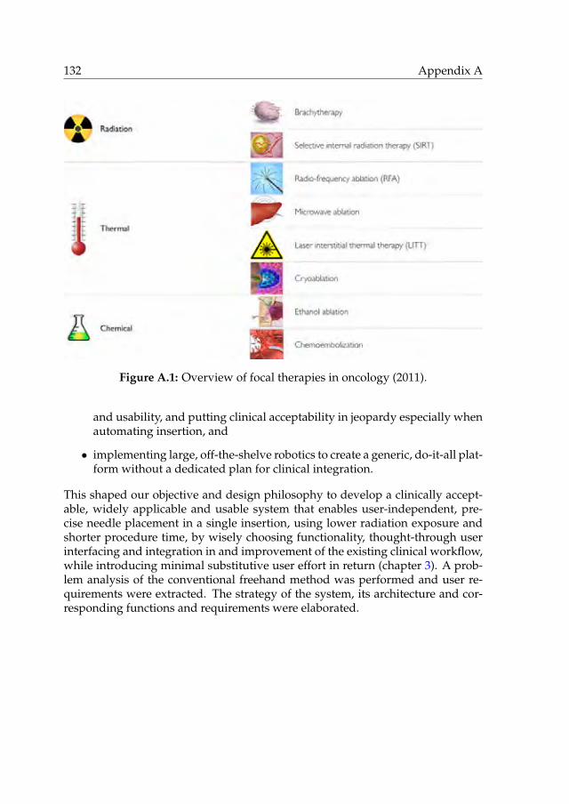
132 Appendix A
Figure A.1: Overview of focal therapies in oncology (2011).
and usability, and putting clinical acceptability in jeopardy especially whenautomating insertion, and
• implementing large, off-the-shelve robotics to create a generic, do-it-all plat-form without a dedicated plan for clinical integration.
This shaped our objective and design philosophy to develop a clinically accept-able, widely applicable and usable system that enables user-independent, pre-cise needle placement in a single insertion, using lower radiation exposure andshorter procedure time, by wisely choosing functionality, thought-through userinterfacing and integration in and improvement of the existing clinical workflow,while introducing minimal substitutive user effort in return (chapter 3). A prob-lem analysis of the conventional freehand method was performed and user re-quirements were extracted. The strategy of the system, its architecture and cor-responding functions and requirements were elaborated.

Development history 133
Figure A.2: Morphological chart of development opportunities (2011).
Figure A.3: Flowchart of CT-guided percutaneous liver tumour ablation (2011).

134 Appendix A
Figure A.4: Morphological chart of the different subsystems (2011).

Development history 135
Figure A.5: Early sketches of the system (2011).
Various concepts for the different subsystems were considered and listed ina morphological chart (Fig. A.4). Figure A.5 shows some of the first sketchesin which the outlines of the final system can clearly be recognized. By the endof 2011, the design had converged and was captured in a first CAD model of thesystem (Fig. A.6). The system’s guided needle placement method and integrationin the clinical workflow were thoroughly reviewed by multiple clinical users. Tofurther substantiate the feasibility of the system’s strategy, needle deflection wasquantified in ex vivo experiments for various clinically used needles (chapter 4).
This marked the start of the detail design of the system (2012-2014), in orderto enable the intended functionality. Mockups of the locking module (LM) andorientation module (OM) were created for workflow simulation and evaluationof the system’s size, shape and action range (Fig. A.7). Objects of various ma-terials and sizes were CT scanned to investigate their X-ray transparency and todemonstrate the feasibility of system-to-CT registration using fiducial markers(Fig. A.8).

136 Appendix A
Figure A.6: First CAD model of the system (2011).
(a) Mock-up of the LM and OM for workflowsimulation (2012).
(b) Plywood mock up of the LM arm for shapeevaluation (2013).
Figure A.7: Mock-ups to evaluate the design.

Development history 137
(a) SLS printed nylon frame holding 10 mm fi-ducial markers of various materials.
(b) A collection of custom material samples.
(c) Rows of 10 mm spheres of different plasticsand ceramics.
(d) Milled POM frame holding four 20 mm alu-minium oxide fidicial markers.
Figure A.8: CT scanning to investigate X-ray transparency and demonstrate thefeasibility of system-to-CT registration using fiducial markers (2012).
(a) Initial experiment setup to investigate thedrive system (2012).
(b) Setup to spin an endless cable, build usingLEGO (2012).
Figure A.9: Development of the drive system (2012-2014).

138 Appendix A
(c) Mould to cast a fibre reinforced endless cable(2013).
(d) Evolved experiment setup, incorporating theelaborated design of the OM (2014).
(e) Assortment of tested cables of various materials and constructions (2014).
Figure A.9: Development of the drive system (2012-2014) – continued.

Development history 139
Figure A.10: Ball joint sketches (2012).
An experiment setup was build to investigate the drive system of the RCMmechanism, incorporating a servomotor, cable drive and worm gear transmis-sion (Fig. A.9). We tried various cable materials including nylon fishing line,polyurethane rubber, PTFE, glass fibre, aramid and Dyneema, and tested theirfriction, slip, and life time performance. For long, creating an endless cable re-mained an unsolved issue, as we tried glueing, knotting, weaving and casting.A spliced Dyneema cable provided a breakthrough in 2013, which was iteratedto perfection in close collaboration with Andre Bizot of Pro Air Paragliding. Incontinued testing we managed to quantify and compensate for the behaviour ofthe cables to shorten over time.
Figure A.10 shows sketches in search of a suited locking ball joint design.Fibre reinforced torsion springs to eliminate play in the drive system andcomposite ball joints were developed in collaboration with Futura Composites(Fig. A.11). The locking performance of various metal and composite ball jointswith and without fibre reinforcement were investigated in an experiment setup(Fig. A.12).

140 Appendix A
(a) Results of initial attempts to cast fibre rein-forced torsion springs (2012).
(b) Evolved torsion springs and composite balljoints (2013).
Figure A.11: Test samples of composite components, developed in collaborationwith Futura Composites.
Figure A.12: Experiment setup to investigate the locking performance of variousball joint designs (2012-2014).

Development history 141
(a) Milling of the SLS printed OM main body atParts & Tools.
(b) Overview of various components beforeasembly.
(c) Segment 1 and 2 assembly. (d) OM subassembly with external motors.
Figure A.13: Realization of a prototype of the preliminary design (2013).
A prototype of the preliminary design was realized in 2013, which consisted ofan empty mockup of the LM and a functional OM using externally attached elec-trical servomotors (Fig. A.13). The system was tested in combination with conebeam CT (CBCT) at the facilities of Philips Healthcare (Fig. A.14), and with CT atthe facilities of the University Medical Center Groningen (UMCG) (Fig. A.15).

142 Appendix A
Figure A.14: Testing of a prototype of the preliminary design with CBCT at thefacilities of Philips Healthcare (2013).

Development history 143
Figure A.15: Testing of a prototype of the preliminary with CT at the facilities ofthe UMCG (2014).
Figure A.16: Experiment setup to investigate the design of the fibre optic en-coders (2013).
During performance testing of the endless Dyneema cable drive, it becameclear that angular feedback would be unavoidable to account for variations inthe transmission rate due to the radial stiffness of the rubberised pulleys, fluctu-ation in cable diameter and cable slip. This posed a new challenge: the develop-ment of custom fibre optic encoders (Fig. A.16). The optical path of light fromone fibre reflected via a mirror to another fibre was investigated in an experimentsetup and a proof-of-principle encoder was build and tested for reliability andmaximum speed. For the final design, a custom printed circuit board contain-ing light-emitting diodes and photodiodes for two encoders was developed andsized to fit inside the LM arm.

144 Appendix A
Figure A.17: Ball joint cable guide sketches (2013-2014).
Yet another challenge lay in the geometric design and material selection of asuitable guidance of the two endless cable drives through the 3-DOFs ball joint 2,which should function for any orientation, avoid wear of the cable and itself andinduce minimal friction. In addition to the two cables passing twice, it shouldprovide a safe passage for eight optical fibres and three carbon nanotube wires,and still allow for assembly. Figure A.17 shows several sketches drawn in searchof a solution.
Various manual and automated mechanisms were conceptualized for thelocking system. Manual locking was dismissed in consideration of usability. Anautomated pneumatic-hydraulic system was chosen for its relative simplicity andan experiment setup was build incorporating the pneumatic-to-hydraulic intens-ifier and three hydraulic cylinders to investigate its performance and technicaldesign (Fig. A.18).
Push-buttons on the OM main body were selected as the most suited user-interfaces for control of the automated locking system, and different conceptswere considered to create X-ray transparent signal routing, including fibre op-tic and aluminium electrical circuits. Carbon nanotube electrical circuits werechosen, and samples of this experimental material were supplied by Teijin Ara-mid. The conductive performance of the wires and the design of custom carbonelectrical switches were investigated (Fig. A.19).

Development history 145
Figure A.18: Experiment setup to investigate the pneumatic-hydraulic lockingsystem (2014).
(a) Measuring the conductivity. (b) Testing a custom carbon electrical switch.
Figure A.19: Experiments to investigate the use of carbon nanotubes as an X-raytransparent electrical circuit (2014).

146 Appendix A
Figure A.20: Design of the gravity compensator using SPACAR (2014).
In order to maintain a static position of the LM arm when released withoutlocking, a gravity compensator consisting of a preloaded eccentric spring mech-anism was designed using flexible multibody modelling in SPACAR (Fig. A.20).
The static structural performances of segment 1 and the LM were analysed forvarious material combinations using a finite element method in Ansys (Fig. A.21).
Algorithms for image segmentation and pose computation (Fig. A.22), seg-ment angle calculations (Fig. A.23) and motion control were developed in Matlab.The intended functional flow of the system was streamlined and correspondinghardware en software user interfaces and internal measurement systems weredefined. Following an initial version of the graphical user interface (GUI) whichcontained many redundant and complicated steps (Fig. A.24), a software flow-chart (Fig. A.25) and a new layout were designed and implemented to reduce thenumber of steps to be executed by the user to a minimum.
Figure A.26 depicts the evolution of the CAD model of the system from 2012to 2014, driven by the knowledge obtained from the various analyses, calcula-tions and experiments. Towards the end of 2014, the detail design of the mainsystem and control box were completed, 2D drawings of the parts to be manu-factured were made (Fig. A.27) and orders were placed. Including tooling, thesystem consists of over 65 subassemblies and over 650 parts, of which over 270are different and over 190 are custom made.

Development history 147
Figure A.21: Static structural analysis of the LM using Ansys (2014).
Figure A.22: 3D CT image segmentation and pose computation (2012-2016).
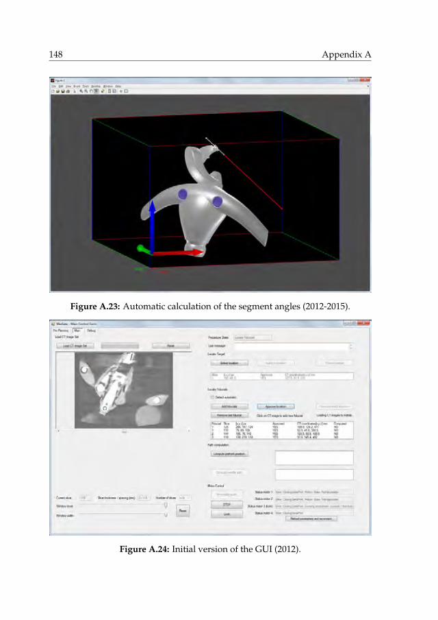
148 Appendix A
Figure A.23: Automatic calculation of the segment angles (2012-2015).
Figure A.24: Initial version of the GUI (2012).

Development history 149
Figure A.25: Software functional flowchart (2014-2015).

150 Appendix A
(a) Early design with actuators in the OM main body and four bevel gears to drive segment 2 (2012),
(b) Exploratory design of remote actuation of the segments using endless cable drives, locking mech-anism of the ball joints, and cable drive in segment 1 to segment 2 (2012).
Figure A.26: Evolution of the CAD model (2012-2014).

Development history 151
(c) Elaboration of the endless cable drives and mechanical locking system (2013).
(d) Converged design of the OM and early design of the pneumatic-hydraulic locking system in theLM foot (2013).
Figure A.26: Evolution of the CAD model (2012-2014) – continued.
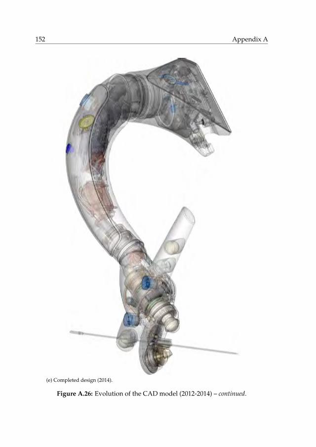
152 Appendix A
(e) Completed design (2014).
Figure A.26: Evolution of the CAD model (2012-2014) – continued.

Development history 153
Figure A.27: Exemplary 2D drawings (2014).

154 Appendix A
Figure A.27: Exemplary 2D drawings (2014) – continued.

Development history 155
Figure A.28: Production of the aluminium oxide segment 2 by milling, sinteringand precision grinding by Ceratec Technical Ceramics (2015).
Early 2015, the realization of a prototype of the completed design started. Fig-ures A.28 to A.37 illustrate the subsequent steps of manufacture and assembly.Figure A.38 illustrates the preliminary assembly of the complete prototype.

156 Appendix A
(a) Glueing O-rings to rubberise the integratedpulleys, to be grinded afterwards.
(b) Glueing silicon nitride balls on top as axialbearings.
Figure A.29: Realization of the silicon nitride worms (2015).
(a) Segment 1 axle assembly. (b) Measuring the axle eccentricities.
(c) Milling segment 1 by Parts & Tools. (d) Cap of segment 1, containing the cone andbevel gear to drive segment 2.
Figure A.30: Realization of the segment 1 subassembly (2015).

Development history 157
(e) Continued milling. (f) Preliminary assembly of segment 1.
(g) Measuring the distance between two fidu-cial markers glued onto the axle.
(h) Installing the glass fibre torsion spring un-der preload using a mounting tool.
(i) Glass fibre torsion spring, worm wheel andslipper clutch after assembly.
(j) Assembly of the ceramic ball bearings.
Figure A.30: Realization of the segment 1 subassembly (2015) – continued.

158 Appendix A
(a) Fitting the bottom cap. (b) Glueing ball joint 2 in place.
(c) Milling the OM main body by Parts & Tools. (d) Milling finished.
(e) Removal of the mounting base after milling. (f) Preliminary subassembly.
Figure A.31: Realization of the OM subassembly (2015).
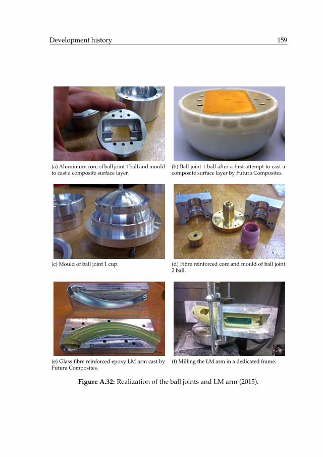
Development history 159
(a) Aluminium core of ball joint 1 ball and mouldto cast a composite surface layer.
(b) Ball joint 1 ball after a first attempt to cast acomposite surface layer by Futura Composites.
(c) Mould of ball joint 1 cup. (d) Fibre reinforced core and mould of ball joint2 ball.
(e) Glass fibre reinforced epoxy LM arm cast byFutura Composites.
(f) Milling the LM arm in a dedicated frame.
Figure A.32: Realization of the ball joints and LM arm (2015).

160 Appendix A
(a) Grinding the rubberised pulleys of the cabledrive.
(b) Glueing the SLS printed motorframe to thealuminium bottom of the LM arm.
(c) Preliminary installation of the motors, spurgears and cable drive tension springs.
(d) Preliminary installation of a Dyneema cable.
(e) Post-processing of the DLP printed pulleyblock part of the cable drive.
(f) Preliminary assembly of OM main body, LMarm and motor frame.
Figure A.33: Realization of the internals of the LM arm (2015).

Development history 161
(a) LM foot main body, produced by electricaldischarge machining and milling by GML In-struments.
(b) Installation of the wheels of the linear slideron their glass fibre spring mount.
(c) Fitting the LM foot on the rail. (d) Assemblying the pneumatic-hydraulic in-tensifier subassembly.
(e) Preliminary filling of the hydraulic systemfor testing.
(f) Finished installation of the lower part of thepneumatic-hydraulic locking system.
Figure A.34: Realization of the LM foot subassembly (2015).

162 Appendix A
(a) Measuring segment 2. (b) Measuring the fiducial markers in the OM.
Figure A.35: Geometric measurements using a FARO Gage Plus measuring arm(2015).
Figure A.36: Realization of the control box (2015).

Development history 163
Figure A.37: Installation of the electrical wiring, optical fibres, carbon nanotubesand endless Dyneema cables (2015).

164 Appendix A
(a) LM foot and pneumatic-hydraulic lockingsystem.
(b) LM arm and endless cable drive.
(c) Drive system of the RCM mechanism. (d) Complete assembly.
Figure A.38: Preliminary assembly of the complete system (2015).
In 2015 and 2016, the prototype was integrated in the intervention suite atthe UMCG (Fig. A.39), extensively tested, debugged, calibrated and technicallyverified (chapter 5). Minor and major modifications of the hardware and soft-ware were applied where necessary. The prototype was carefully finished withan outer layer of paint for looks and varnish for secure cleaning and disinfec-tion. Clinical users were introduced to the system (Fig. A.40) and the system waspre-clinically validated in a phantom study (chapter 6) (Fig. A.41).
Towards clinical deployment, a dedicated CT table interface was elaboratedto replace the short rail on a provisional frame of aluminium profiles (Fig. A.42).Based on measurements of the table size and shape, carbon fibre reinforced epoxyand foam sandwich constructions for a matching table plate and rail were de-signed to cover the full length of the table in three sections. A more economicaldesign intended to remain outside the CT scanned volume was eventually real-ized, consisting of two water jet cut steel mounts matching the shape of the tableand an aluminium rail of half the length of the table.

Development history 165
Figure A.39: The author integrating the system in the intervention suite (2015).
(a) Creating a skin incision at the RCM. (b) Manual insertion after automated aiming.
Figure A.40: Introduction of the prototype to clinical users at the UMCG (2016).

166 Appendix A
Figure A.41: Validation of the system in a phantom study (2016).
(a) Size and shape measurements of the CT table. (b) Fitting a template of the interface.
(c) Design of a full-length carbon fibre reinforcedinterface.
(d) Realized interface consisting of an aluminumrail on steel mounts.
Figure A.42: Development of the CT table interface (2016).

Development history 167
Figure A.43: EMC testing of the system at Thales (2017).
Electromagnetic compatibility (EMC) of the system is required according toEN 55011, class B. Electromagnetic emission was measured in a radio frequencyanechoic chamber at the ISO/IEC 17025 L240 accredited test laboratory of theThales Environmental Competence Centre (Fig. A.43). The results were in com-pliance with the applicable standard.
To obtain permission from the Medical Ethical Committee of the UMCG andthe Dutch Health Care Inspectorate (IGZ) for clinical deployment of the system,we delivered a long list of signed paperwork produced over the course of the de-velopment, including the system requirements documents, concept design docu-ments, software interface design documents, the bill of materials, the software re-vision level history, test and analysis reports (system, electrical and software), re-quirement verification reports, component sterilization instructions, declarationsof suitability for sterilization, pre-clinical evidence, a user manual, user trainingrecords, the risk management file, the essential requirements checklist, the invest-igational medical device dossier, and the IEC 60601 checklist.
Figure A.44 shows the completed system in 2017, ready for deployment inclinical practise.
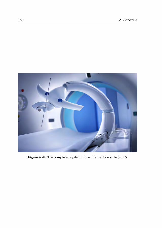
168 Appendix A
Figure A.44: The completed system in the intervention suite (2017).

References
[1] DEMCON, Institutenweg 25, 7521 PH, Enschede, the Netherlands. ht-tps://www.demcon.nl.
[2] University of Twente, Drienerlolaan 5, 7522 NB, Enschede, the Nether-lands. https://www.utwente.nl.
[3] D. Patch and A.P. Dhillon. Biopsy of the liver. In J.S. Dooley, A.S. Lok,A.K. Burroughs, and E.J. Heathcote, editors, Sherlock’s diseases of the liverand biliary system, chapter 3, pages 36–47. Wiley-Blackwell, Hoboken, NewJersey, USA, 12th edition, 2011.
[4] R.S. Winokur, B.B. Pua, B.W. Sullivan, and Madoff D.C. Percutaneous lungbiopsy: technique, efficacy, and complications. Seminars in InterventionalRadiology, 30(2):121–127, 2013.
[5] J. Scheele, A. Altendorf-Hofmann, R. Stangl, and K. Schmidt. Surgical re-section of colorectal liver metastases: gold standard for solitary and radic-ally resectable lesions. Swiss Surgery, 4:4–17, 1996.
[6] Registry of Hepatic Metastases. Resection of the liver for colorectal car-cinoma metastases: a multi-institutional study of indications for resection.Surgery, 103(3):278–288, 1988.
[7] P. Rougier, C. Milan, F. Lazorthes, G. Fourtanier, C. Partensky, H. Baumel,and J. Faivre. Prospective study of prognostic factors in patients with unre-sected hepatic metastases from colorectal cancer. British Journal of Surgery,82(10):1397–1400, 1995.
[8] M.G. Hartwig and T.A. D’Amico. Thoracoscopic lobectomy: the goldstandard for early-stage lung cancer? The Annals of Thoracic Surgery,89(6):S2098–S2101, 2010.
[9] A.S. Wright, D.M. Mahvi, D.G. Haemmerich, and F.T. Lee. Minimally in-vasive approaches in management of hepatic tumors. Surgical TechnologyInternational, 11:144–153, 2003.
[10] A.R. Gillams. Image guided tumour ablation. Cancer Imaging, 5:103–109,2005.
[11] M. Ahmed, C.L. Brace, F.T. Lee, and S.N. Goldberg. Principles of and ad-vances in percutaneous ablation. Radiology, 258(2):351–369, 2011.
169

170
[12] D. Li, J. Kang, B.J. Golas, V.W. Yeung, and D.C. Madoff. Minimally invasivelocal therapies for liver cancer. Cancer Biology & Medicine, 11(4):217–236,2014.
[13] D.E. Dupuy and M. Shulman. Current status of thermal ablation treatmentsfor lung malignancies. Seminars in Interventional Radiology, 27(3):268–275,2010.
[14] P.D. Sonntag, J.L. Hinshaw, M.G. Lubner, C.L. Brace, and F.T Lee. Thermalablation of lung tumors. Surgical Oncology Clinics of North America,20(2):369–387, 2011.
[15] Y. Robert Sheu and K. Hong. Percutaneous lung tumor ablation. Techniquesin Vascular & Interventional Radiology, 16(4):239–252, 2013.
[16] T. Schneider, C.P. Heussel, F.J.F. Herth, and H. Dienemann. Thermalablation of malignant lung tumors. Deutsches Ärzteblatt International,110(22):394–400, 2013.
[17] E.S. Alexander and D.E. Dupuy. Lung cancer ablation: technologies andtechniques. Seminars in Interventional Radiology, 30(2):141–150, 2013.
[18] Q.Z. Al-Tariq. Percutaneous strategies for the management of pulmonaryparenchymal, chest wall, and pleural metastases. American Journal of Roent-genology, 203(4):709–716, 2014.
[19] L.A. Torre, F. Bray, R.L. Siegel, J. Ferlay, J. Lortet-Tieulent, and A. Jemal.Global cancer statistics, 2012. CA: A Cancer Journal for Clinicians, 65(2):87–108, 2015.
[20] W.T. London and McGlynn K.A. Liver cancer. In D. Schottenfeld and J.F.Fraumeni, Jr., editors, Cancer Epidemiology and Prevention, chapter 39, pages763–786. Oxford University Press, New York City, New York, USA, 3rd edi-tion, 2006.
[21] J.G. Geoghegan and J. Scheele. Treatment of colorectal liver metastases.British Journal of Surgery, 86(2):158–169, 1999.
[22] S.B. Solomon and S.G. Silverman. Imaging in interventional oncology. Ra-diology, 257(3):624–640, 2010.
[23] M. Ahmed, L. Solbiati, C.L. Brace, D.J. Breen, M.R. Callstrom, J.W. Char-boneau, M. Chen, B. Ihn Choi, T. de Baère, G.D. Dodd, III, D.E. Dupuy, D.A.Gervais, D. Gianfelice, A.R. Gillams, F.T. Lee, Jr., E. Leen, R. Lencioni, P.J.Littrup, T. Livraghi, D.S. Lu, J.P. McGahan, M. Franca Meloni, B. Nikolic,P.L. Pereira, P. Liang, H. Rhim, S.C. Rose, R. Salem, C.T. Sofocleous, S.B.Solomon, M.C. Soulen, M. Tanaka, T.J. Vogl, B.J. Wood, and S.N. Goldberg.Image-guided tumor ablation: standardization of terminology and report-ing criteria - a 10-year update. Radiology, 273(1):241–260, 2014.

References 171
[24] D.S. Memel, G.D. Dodd, and C.C. Esola. Efficacy of sonography as a guid-ance technique for biopsy of abdominal, pelvic, and retroperitoneal lymphnodes. American Journal of Roentgenology, 167(4):957–962, 1996.
[25] L. Appelbaum, R.A. Kane, J.B. Kruskal, J. Romero, and J. Sosna. Focalhepatic lesions: US-guided biopsy - lessons from review of cytologic andpathologic examination results. Radiology, 250(2):453–458, 2009.
[26] G. Vijayaraghavan, S. David, M. Bermudez-Allende, and H. Sarwat.Imaging-guided parenchymal liver biopsy: how we do it. Journal of ClinicalImaging Science, 1(1):30, 2011.
[27] S. Rossi, M. Di Stasi, E. Buscarini, P. Quaretti, F. Garbagnati, L. Squassante,C.T. Paties, D.E. Silverman, and L. Buscarini. Percutaneous RF interstitialthermal ablation in the treatment of hepatic cancer. American Journal ofRoentgenology, 167(3):759–768, 1996.
[28] S.A. Curley, F. Izzo, P. Delrio, L.M. Ellis, J. Granchi, P. Vallone, F. Fiore,S. Pignata, B. Daniele, and F. Cremona. Radiofrequency ablation of unre-sectable primary and metastatic hepatic malignancies: results in 123 pa-tients. Annals of Surgery, 280(1):1–8, 1999.
[29] L. Solbiati, T. Livraghi, S.N. Goldberg, T. Ierace, F. Meloni, M. Dellanoce,L. Cova, E.F. Halpern, and G.S. Gazelle. Percutaneous radio-frequency ab-lation of hepatic metastases from colorectal cancer: long-term results in 117patients. Radiology, 221(1):159–166, 2001.
[30] R. Lencioni, D. Cioni, L. Crocetti, C. Franchini, C. Della Pina, J. Lera, andC. Bartolozzi. Early-stage hepatocellular carcinoma in patients with cir-rhosis: long-term results of percutaneous image-guided radiofrequency ab-lation. Radiology, 234(3):961–967, 2005.
[31] L. Solbiati, M. Ahmed, L. Cova, T. Ierace, M. Brioschi, and S.N. Goldberg.Small liver colorectal metastases treated with percutaneous radiofrequencyablation: local response rate and long-term survival with up to 10-yearfollow-up. Radiology, 265(3):958–968, 2012.
[32] S.R. Wilson, L.D. Greenbaum, and B.B. Goldberg. Contrast-enhanced ultra-sound: what is the evidence and what are the obstacles? American Journalof Roentgenology, 193(1):55–60, 2009.
[33] Bracco Diagnostics Inc. First Approval by U.S. Food and Drug Administra-tion for contrast enhanced ultrasonography of the liver received by BraccoDiagnostics Inc. for LUMASON R© (sulfur hexafluoride lipid-type A micro-spheres) for injectable suspension, for intravenous use. Press release, Mon-roe Township, New Jersey, USA, April 4, 2016.

172
[34] S.K. Bhargava and A.K. Srivastava. Interaction of ultrasound with matter.In S.K. Bhargava, editor, Principles and practice of ultrasonography, chapter 3,pages 10–15. Jaypee Brothers Medical Publishers (P) Ltd., New Delhi, India,1st edition, 2002.
[35] Siemens Aktiengesellschaft, Wittelsbacherplatz 2, 80333, Munich, Ger-many. https://www.siemens.com.
[36] W.A. Kalender. X-ray computed tomography. Physics in Medicine and Bio-logy, 51(13):R29–R43, 2006.
[37] H.K. Ha, P.B. Sachs, J.R. Haaga, and F. Abdul-Karim. CT-guided liverbiopsy: an update. Clinical Imaging, 15(2):99–104, 1991.
[38] L. Thanos, A. Zormpala, G. Papaioannou, K. Malagari, E. Brountzos, andD. Kelekis. Safety and efficacy of percutaneous CT-guided liver biopsyusing an 18-gauge automated needle. European Journal of Internal Medicine,16(8):571–574, 2005.
[39] B.J. Park, J.H. Byun, Y.H. Jin, H.J. Won, Y.M. Shin, K.W. Kim, S.J. Park,and P.N. Kim. CT-guided radiofrequency ablation for hepatocellular car-cinomas that were undetectable at US: therapeutic effectiveness and safety.Journal of Vascular and Interventional Radiology, 20(4):490–499, 2009.
[40] F. Laspas, E. Sotiropoulou, S. Mylona, A. Manataki, P. Tsagouli, I. Tsangar-idou, and L. Thanos. Computed tomography-guided radiofrequency ab-lation of hepatocellular carcinoma: treatment efficacy and complications.Journal of Gastrointestinal and Liver Diseases, 18(3):323–328, 2009.
[41] I. Tsai, W. Tsai, M. Chen, G. Chang, W. Tzeng, S. Chan, and C.C. Chen.CT-guided core biopsy of lung lesions: a primer. American Journal of Roent-genology, 193(5):1228–1235, 2009.
[42] G. Belfiore, G. Moggio, E. Tedeschi, M. Greco, R. Cioffi, F. Cincotti, andR. Rossi. CT-guided radiofrequency ablation: a potential complementarytherapy for patients with unresectable primary lung cancer - a preliminaryreport of 33 patients. American Journal of Roentgenology, 183(4):1003–1011,2004.
[43] R. Lencioni, L. Crocetti, R. Cioni, R. Suh, D. Glenn, D. Regge, T. Helmber-ger, A. Gillams, A. Frilling, M. Ambrogi, C. Bartolozzi, and A. Mussi. Re-sponse to radiofrequency ablation of pulmonary tumours: a prospective,intention-to-treat, multicentre clinical trial (the RAPTURE study). The Lan-cet Oncology, 9(7):621–628, 2008.
[44] M.D. Beland, E.J. Wasser, W.W. Mayo-Smith, and D.E. Dupuy. Primarynon–small cell lung cancer: review of frequency, location, and time of re-currence after radiofrequency ablation. Radiology, 254(1):301–307, 2010.

References 173
[45] A. Gillams, Z. Khan, P. Osborn, and W. Lees. Survival after radiofrequencyablation in 122 patients with inoperable colorectal lung metastases. Cardi-oVascular and Interventional Radiology, 36(3):724–730, 2013.
[46] M.A. Kliewer, D.H. Sheafor, E.K. Paulson, R.S. Helsper, B.S. Hertzberg,and R.C. Nelson. Percutaneous liver biopsy: a cost-benefit analysis com-paring sonographic and CT guidance. American Journal of Roentgenology,173(5):1199–1202, 1999.
[47] D.V. Sahani and S.P. Kalva. Imaging the liver. The Oncologist, 9(4):385–397,2004.
[48] J.R. McCarley and M.C. Soulen. Percutaneous ablation of hepatic tumors.Seminars in Interventional Radiology, 27(3):255–260, 2010.
[49] C.H. Cha, F.T. Lee, J.M. Gurney, B.K. Markhardt, T.F. Warner, F. Kelcz, andD.M. Mahvi. CT versus sonography for monitoring radiofrequency abla-tion in a porcine liver. American Journal of Roentgenology, 175(3):705–711,2000.
[50] B. Daly and P.A. Templeton. Real-time CT fluoroscopy: evolution of aninterventional tool. Radiology, 211(2):309–315, 1999.
[51] H.S. Hwang, M.J. Chung, J.W. Lee, S.W. Shin, and K.S. Lee. C-arm cone-beam CT-guided percutaneous transthoracic lung biopsy: usefulness inevaluation of small pulmonary nodules. American Roentgen Ray Society,195(6):W400–W407, 2010.
[52] J.W. Choi, C.M. Park, J.M. Goo, Y. Park, W. Sung, H. Lee, S.M. Lee,J.Y. Ko, and M. Shim. C-arm cone-beam CT–guided percutaneous tran-sthoracic needle biopsy of small (¤ 20 mm) lung nodules: diagnostic ac-curacy and complications in 161 patients. American Journal of Roentgenology,199(3):W322–W330, 2012.
[53] J.Y. Choo, C.M. Park, N.K. Lee, S.M. Lee, H. Lee, and J.M. Goo. Percu-taneous transthoracic needle biopsy of small (¤1 cm) lung nodules un-der C-arm cone-beam CT virtual navigation guidance. European Radiology,23(3):712–719, 2013.
[54] S.M. Lee, C.M. Park, K.H. Lee, Y.E. Bahn, J.I. Kim, and J.M. Goo. C-armcone-beam CT-guided percutaneous transthoracic needle biopsy of lungnodules: clinical experience in 1108 patients. Radiology, 271(1):291–300,2014.
[55] M. Abdel-Rehim, M. Ronot, A. Sibert, and V. Vilgrain. Assessment of liverablation using cone beam computed tomography. World Journal of Gastroen-terology, 21(2):517–524, 2015.
174
[56] N. Abi-Jaoudeh, A.M. Venkatesan, W. van der Sterren, A. Radaelli,B. Carelsen, and B.J. Wood. Clinical experience with cone-beam CT nav-igation for tumor ablation. Journal of Vascular and Interventional Radiology,26(2):214–219, 2015.
[57] M. Morimoto, K. Numata, M. Kondo, A. Nozaki, S. Hamaguchi, S. Take-bayashi, and K. Tanaka. C-Arm Cone Beam CT for Hepatic Tumor Ab-lation Under Real-Time 3D Imaging. American Journal of Roentgenology,194(5):W452–W454, 2010.
[58] R.L. Cazzato, J. Battistuzzi, V. Catena, R.F. Grasso, B.B. Zobel, E. Schena,X. Buy, and J. Palussiere. Cone-beam computed tomography (CBCT) versusCT in lung ablation procedure: which is faster? CardioVascular and Inter-ventional Radiology, 38(5):1231–1236, 2015.
[59] R.C. Orth, M.J. Wallace, and M.D. Kuo. C-arm cone-beam CT: generalprinciples and technical considerations for use in interventional radiology.Journal of Vascular and Interventional Radiology, 19(6):814–820, 2008.
[60] Y. Cheng, S. Tsai, Y. Cheng, J. Chen, J. Chai, and C.C. Chen. Percutaneoustransthoracic lung biopsy: comparison between C-arm cone-beam CT andconventional CT guidance. Translational Oncology, 8(4):258–264, 2015.
[61] B.M. Dale, M.A. Brown, and R.C. Semelka. MRI: Basic principles and applic-ations. 5th edition, 2015.
[62] F. Fischbach, J. Bunke, M. Thormann, G. Gaffke, K. Jungnickel, J. Smink,and J. Ricke. MR-guided freehand biopsy of liver lesions with fast continu-ous imaging using a 1.0-T open MRI scanner: Experience in 50 patients.CardioVascular and Interventional Radiology, 34(1):188–192, 2011.
[63] E. Salomonowitz. MR imaging-guided biopsy and therapeutic interventionin a closed-configuration magnet: Single-center series of 361 punctures.American Journal of Roentgenology, 177(1):159–163, 2001.
[64] J. Kettenbach, W. Köstler, E. Rücklinger, B. Gustorff, M. Hüpfl, F. Wolf,K. Peer, M. Weigner, J. Lammer, W. Müller, and S.N. Goldberg. Percu-taneous saline-enhanced radiofrequency ablation of unresectable hepatictumors: Initial experience in 26 patients. American Journal of Roentgenology,180(6):1537–1545, 2003.
[65] J. Kariniemi, R. Blanco Sequeiros, R. Ojala, and O. Tervonen. MRI-guidedabdominal biopsy in a 0.23-T open-configuration MRI system. EuropeanRadiology, 15(6):1256–1262, 2005.
[66] J. Stattaus, S. Maderwald, H.A. Baba, G. Gerken, J. Barkhausen, M. Forst-ing, and M.E. Ladd. MR-guided liver biopsy within a short, wide-bore 1.5Tesla MR system. European Radiology, 18(12):2865–2873, 2008.

References 175
[67] M. Moche, S. Heinig, N. Garnov, J. Fuchs, T. Petersen, D. Seider, P. Brand-maier, T. Kahn, and H. Busse. Navigated MRI-guided liver biopsies ina closed-bore scanner: experience in 52 patients. European Radiology,26(8):2462–2470, 2016.
[68] M. Liu, Y. Lv, L. Wu, J. Song, R.B. Sequeiros, and C. Li. MRI-guided percu-taneous coaxial cutting needle biopsy of small pulmonary nodules: feasib-ility. European Radiology, 23(10):2730–2738, 2013.
[69] S. Clasen and P.L. Pereira. Magnetic resonance guidance for radiofrequencyablation of liver tumors. Journal of Magnetic Resonance Imaging, 27(2):421–433, 2008.
[70] F.G. Abtin, J. Eradat, A.J. Gutierrez, C. Lee, M.C. Fishbein, and R.D. Suh.Radiofrequency ablation of lung tumors: imaging features of the postabla-tion zone. RadioGraphics, 32(4):947–969, 2012.
[71] M. Arnolli, M. Franken, and M. Buijze, inventors. DEMCON AdvancedMechatronics B.V., applicant. System and method for aligning a medicaldevice. WO patent application, WO2015/041516 A1, September 23, 2013.
[72] M.M. Arnolli, N.C. Hanumara, M. Franken, D.M. Brouwer, and I.A.M.J.Broeders. An overview of systems for CT- and MRI-guided percutaneousneedle placement in the thorax and abdomen. The International Journal ofMedical Robotics and Computer Assisted Surgery, 11(4):458–475, 2015.
[73] E.A. Spiegel, H.T. Wycis, M. Marks, and A.J. Lee. Stereotaxic apparatus foroperations on the human brain. Science, 106(2754):349–350, 1947.
[74] Y.S. Kwoh, J. Hou, E.A. Jonckheere, and S. Hayati. A robot with improvedabsolute positioning accuracy for CT guided stereotactic brain surgery.IEEE Transactions on Biomedical Engineering, 35(2):153–160, 1988.
[75] G. Fichtinger, E.C. Burdette, A. Tanacs, A. Patriciu, D. Mazilu, L.L. Whit-comb, and D. Stoianovici. Robotically assisted prostate brachytherapy withtransrectal ultrasound guidance - phantom experiments. Brachytherapy,5(1):14–26, 2006.
[76] M. Muntener, A. Patriciu, D. Petrisor, D. Mazilu, H. Bagga, L. Kavoussi,K. Cleary, and D. Stoianovici. Magnetic resonance imaging compatible ro-botic system for fully automated brachytherapy seed placement. Urology,68(6):1313–1317, 2006.
[77] R.H. Taylor and D. Stoianovici. Medical robotics in computer-integratedsurgery. IEEE Transactions on Robotics and Automation, 19(5):765–781, 2003.
[78] K. Cleary, A. Melzer, V. Watson, G. Kronreif, and D. Stoianovici. Interven-tional robotic systems: applications and technology state-of-the-art. Min-imally Invasive Therapy & Allied Technologies, 15(2):101–113, 2006.

176
[79] Stryker, 2825 Airview Boulevard, Kalamazoo, Michigan, 49002, USA.http://www.stryker.com.
[80] C. Wu, inventor; Stryker Corporation, assignee. Shielded surgical navig-ation system that determines the position and orientation of the trackedobject with real and virtual dipoles. US patent 8,571,636 B2, October 29,2013.
[81] ActiViews, Inc., 591 North Avenue, Entry One, Wakefield, Massachusetts,01880, USA. http://www.activiews.com.
[82] P. Gilboa, inventor; Activiews Ltd., assignee. System and method for op-tical position measurement and guidance of a rigid or semi-flexible tool toa target. US patent 7,876,942 B2, January 25, 2011.
[83] Northern Digital Inc., 103 Randall Drive, Waterloo, Ontario, N2V 1C5,Canada. http://www.ndigital.com.
[84] E.B. Levy, J. Tang, D. Lindisch, N. Glossop, F. Banovac, and K. Cleary. Im-plementation of an electromagnetic tracking system for accurate intrahep-atic puncture needle guidance: accuracy results in an in vitro model. Aca-demic Radiology, 14(3):344–354, 2007.
[85] Royal Philips, Amstelplein 2, Breitner Center, 1096 BC, Amsterdam, theNetherlands. http://www.philips.com.
[86] J.H. Yanof, L.L. Goldstein, F.C. Jensen, J.C. Foster, and C. Bauer, invent-ors; Picker International Inc., assignee. Interchangeable guidance devicesfor C.T. assisted surgery and method of using same. US patent 5,957,933,September 28, 1999.
[87] Claron Technology Inc., 120 Carlton Street, Suite 217, Toronto, Ontario,M5A 4K2, Canada. http://www.clarontech.com.
[88] L. Maier-Hein, A. Tekbas, A. Seitel, F. Pianka, S.A. Müller, S. Satzl,S. Schawo, B. Radeleff, R. Tetzlaff, A.M. Franz, B.P. Müller-Stich, I. Wolf,H. Kauczor, B.M. Schmied, and H. Meinzer. In vivo accuracy assessment ofa needle-based navigation system for CT-guided radiofrequency ablationof the liver. Medical Physics, 35(12):5385–5396, 2008.
[89] K.A. Gavaghan, S. Anderegg, M. Peterhans, T. Oliveira-Santos, andS. Weber. Augmented reality image overlay projection for image guidedopen liver ablation of metastatic liver cancer. In Augmented Environmentsfor Computer-Assisted Interventions, volume 7264 of Lecture Notes in ComputerScience, pages 36–46. 2012.
[90] Medtronic, 710 Medtronic Parkway, Minneapolis, Minnesota, 55432-5604,USA. http://www.medtronic.com.

References 177
[91] Pathfinder, 2969 Armory Drive, Suite 100A, Nashville, Tennessee, 37204,USA. http://www.pathnav.com.
[92] CAScination AG, Stauffacherstrasse 78, 3008 Bern, Switserland.http://www.cascination.com.
[93] F. Banovac, N. Glossop, D. Lindisch, D. Tanaka, E. Levy, and K. Cleary.Liver tumor biopsy in a respiring phantom with the assistance of a novelelectromagnetic navigation device. In Proceedings of the International Con-ference on Medical Image Computing and Computer-Assisted Intervention (MIC-CAI), volume 2488 of Lecture Notes in Computer Science, pages 200–207, 2002.
[94] B.J. Wood, H. Zhang, A. Durrani, N. Glossop, S. Ranjan, D. Lindisch,E. Levy, F. Banovac, J. Borgert, S. Krueger, J. Kruecker, A. Viswanathan, andK. Cleary. Navigation with electromagnetic tracking for interventional ra-diology procedures: a feasibility study. Journal of Vascular and InterventionalRadiology, 16(4):493–505, 2005.
[95] M. Nagel, M. Hoheisel, R. Petzold, W.A. Kalender, and U.H.W. Krause.Needle and catheter navigation using electromagnetic tracking forcomputer-assisted C-arm CT interventions. In Medical Imaging 2007: Visu-alization and Image-Guided Procedures. Proceedings of the SPIE, volume 6509,pages 65090J–1–65090J–9, 2007.
[96] Krücker, J. and Xu, S. and Glossop, N. and Viswanathan, A. and Borgert, J.and Schulz, H. and Wood, B.J. Electromagnetic tracking for thermal abla-tion and biopsy guidance: clinical evaluation of spatial accuracy. Journal ofVascular and Interventional Radiology, 18(9):1141–1150, 2007.
[97] B.C. Meyer, O. Peter, M. Nagel, M. Hoheisel, B.B. Frericks, K. Wolf, andF.K. Wacker. Electromagnetic field-based navigation for percutaneouspunctures on C-arm CT: experimental evaluation and clinical application.European Radiology, 18(12):2855–2864, 2008.
[98] M. Nagel, M. Hoheisel, U. Bill, K. Klingenbeck-Regn, W.A. Kalender, andR. Petzold. Electromagnetic tracking system for minimal invasive interven-tions using a C-arm system with CT option: first clinical results. In MedicalImaging 2008: Visualization, Image-guided Procedures, and Modeling. Proceed-ings of the SPIE, volume 6918, pages 69180G–1–69180G–10, 2008.
[99] J.H. Yanof, P.H. Klahr, and L. O’Donnell, inventors; Picker InternationalInc., assignee. Frameless stereotactic CT scanner with virtual needle dis-play for planning image guided interventional procedures. US patent6,064,904, May 16, 2000.
[100] J.M. Hevezi, M. Blough, D. Hoffmeyer, and J.H. Yanof. Brachytherapy us-ing CT PinPoint. MEDICAMUNDI, 46(3):22–27, 2002.

178
[101] Immersion Corporation, 30 Rio Robles, San Jose, California, 95134, USA.http://www.immersion.com.
[102] A.M. Palestrant, inventor. Guidance device for C.T. guided drainage andbiopsy procedures. US patent 4,733,661, March 29, 1988.
[103] A. Palestrant, inventor. Guidance device for C.T. guided drainage andbiopsy procedures. US patent 5,102,391, April 7, 1992.
[104] H. Zhang, S. Feng, and W. Feng, inventors; H. Zhang, S. Feng, and ZhejiangKindly Medical Devices Co., Ltd., assignees. Guided puncturing needleand puncturing guiding method. US patent 8,241,301 B2, August 14, 2012.
[105] Inrad, Inc., 4375 Donker Ct. SE, Kentwood, Michigan, 49512, USA.http://www.inrad-inc.com.
[106] R.E. Davis, and J.E. Drace, inventors; DLP, Inc., assignee. Goniometer forneedle placement. US patent 5,196,019, March 23, 1993.
[107] A.M. Palestrant. Comprehensive approach to CT-guided procedures witha hand-held guidance device. Radiology, 174(1):270–272, 1990.
[108] P.R. Frederick, inventor. Three-dimensional light guidance system for in-vasive procedures. US patent 4,651,732, March 24, 1987.
[109] E. Unger, and F.S. Pereles, inventors; ImaRx Pharmaceutical Corp., as-signee. Apparatus for performing biopsies and the like. US patent5,628,327, May 13, 1997.
[110] LAP GmbH Laser Applikationen, Zeppelinstraße 23, 21337, Lüneburg,Germany. http://www.lap-laser.com.
[111] V. Jacobi, A. Thalhammer, and J. Kirchner. Value of a laser guidance systemfor CT interventions: a phantom study. European Radiology, 9(1):137–140,1999.
[112] NeoRad AS, Gaustadalléen 21, 0349, Oslo, Norway.http://www.neorad.no.
[113] K. Brabrand, inventor; NeoRad A/S, assignee. Apparatus for assistingpercutaneous computed tomography-guided surgical activity. US patent6,021,342, February 1, 2000.
[114] amedo Smart Tracking Solutions GmbH, Universitätsstraße 142, 44799, Bo-chum, Germany. http://www.amedo-gmbh.com.
References 179
[115] C. Moser, J. Becker, M. Deli, M. Busch, M. Boehme, and D.H.W. Groene-meyer. A novel laser navigation system reduces radiation exposure andimproves accuracy and workflow of CT-guided spinal interventions: a pro-spective, randomized, controlled, clinical trial in comparison to conven-tional freehand puncture. European Journal of Radiology, 82(4):627–632, 2013.
[116] P.R. Frederick, T.H. Brown, M.H. Miller, A.L. Bahr, and K.H. Taylor. A light-guidance system to be used for CT-guided biopsy. Radiology, 154(2):535–536, 1985.
[117] H. Ishizaka, T. Katsuya, Y. Koyama, H. Ishijima, T. Moteki, and J. Aoki.CT-guided percutaneous intervention using a simple laser director device.American Journal of Roentgenology, 170(3):745–746, 1998.
[118] F.S. Pereles, M. Baker, R. Baldwin, E. Krupinski, and E.C. Unger. Accur-acy of CT biopsy: laser guidance versus conventional freehand techniques.Academic Radiology, 5(11):766–770, 1998.
[119] A. Rockseisen, inventor; LAP GmbH Laser Applikationen, assignee. Tar-get apparatus for linearly inserting an instrument into a human body. USpatent 5,707,360, January 13, 1998.
[120] A. Rockseisen, inventor; LAP GmbH, assignee. Targetting device for thestraight-lined introduction of an instrument into a human body. US patent6,044,291, March 28, 2000.
[121] R. Kloeppel, T. Weisse, F. Deckert, W. Wilke, and S. Pecher. CT-guidedintervention using a patient laser marker system. European Radiology,10(6):1010–1014, 2000.
[122] J. Regn, inventor; Siemens Aktiengesellschaft, assignee. Device for makinga guide path for an instrument on a patient. US patent 6,041,249, March 21,2000.
[123] K. Brabrand, inventor; NeoRad A/S, assignee. Method and apparatus forassisting percutaneous computed tomography-guided surgical activity. USpatent 6,334,067 B1, December 25, 2001.
[124] K. Brabrand, O.H. Eriksen, Ø. Låg, J.M. Bendiksen, D.A. Hansen, and S.Småstuen, inventors; NeoRad A/S, assignee. Apparatus for light beamguided biopsy. US patent 6,443,960 B1, September 3, 2002.
[125] G.A. Krombach, T. Schmitz-Rode, B.B. Wein, J. Meyer, J.E. Wildberger,K. Brabant, and R.W. Günther. Potential of a new laser target systemfor percutaneous CT-guided nerve blocks: technical note. Neuroradiology,42(11):838–841, 2000.

180
[126] Z. Varro, J.K. Locklin, and B.J. Wood. Laser navigation for radiofrequencyablation. Cardiovascular and Interventional Radiology, 27(5):512–515, 2004.
[127] M. Busch, M. Deli, J. Speder, and D. Groenemeyer, inventors; amedoGmbH, assignee. Needle positioning system. World Intellectual PropertyOrganization patent WO 2006/125605 A1, November 30, 2006.
[128] B.J. Wood and J.H. Yanof. CT-guided interventional oncology - bridging thegap between diagnosis and therapy. MEDICAMUNDI, 49(3):28–32, 2005.
[129] J. Yanof, C. Bauer, S. Renisch, A. Lala, P. Klahr, D. Haemmerich, andB. Wood. CT-integrated treatment planning for robot-assisted, laser-guidedradiofrequency ablation. In Proceedings of the Computer Assisted Radiologyand Surgery 19th International Congress and Exhibition, volume 1281, page1361, 2005.
[130] M.Z. Chang, C.M. Yeh, and C.Y. Yeh, inventors. Positioning device for per-cutaneous needle insertion. US patent 4,841,967, June 27, 1989.
[131] K. Brabrand, N. Bérard-Andersen, G.F. Olsen, and V. Bakke, inventors; Ne-oRad A/S, applicant. Needle holder. US patent application 2012/0022368A1, January 26, 2012.
[132] AprioMed AB, Virdings Allé 28, 754 50, Uppsala, Sweden.http://www.apriomed.com.
[133] A. Eklund, A. Tiensuu, and E. Nicklasson, inventors; RADI MEDICAL SYS-TEMS AB, applicant. Medical guide for guiding a medical instrument. USpatent application 2008/0200798 A1, August 21, 2008.
[134] R. Gupta, S.R.H. Barrett, N.C. Hanumara, J.O. Shepard, A.H. Slocum, andC.J. Walsh, inventors. Guidance and insertion system. US patent applica-tion 2006/0229641 A1, October 12, 2006.
[135] S. Song, J. Tokuda, K. Tuncali, A. Yamada, M. Torabi, and N. Hata. Designevaluation of a double ring RCM mechanism for robotic needle guidance inMRI-guided liver interventions. In Proceedings of the IEEE/RSJ InternationalConference on Intelligent Robots and Systems (IROS), pages 4078–4083, 2013.
[136] M. Demathelin, and B. Maurin, B. Bayle, J. Gangloff, and O. Piccin, invent-ors; Institut National des Sciences Appliquees, Institut de Recherche surles Cancers de l’Appareil Digestif - IRCAD, Universite Louis Pasteur, andCentre National de la Recherche Scientifique, assignees. Robotic position-ing and orientation device and needle holder comprising one such device.US patent 7,881,823 B2, February 1, 2011.
[137] I. Bricault, N. Zemiti, E. Jouniaux, C. Fouard, E. Taillant, F. Dorandeu, andP. Cinquin. A Light Puncture Robot for CT and MRI interventions. IEEEEngineering in Medicine and Biology Magazine, 27(3):42–50, 2008.

References 181
[138] A. Magnusson, E. Radecka, M. Lönnemark, and H. Raland. Computed-tomography-guided punctures using a new guidance device. Acta Radiolo-gica, 46(5):505–509, 2005.
[139] A. Magnusson, and P. Egnelöv, inventors; Aprio Medical AB, assignee.Guide for a medical device. US patent 7,824,417 B2, November 2, 2010.
[140] S.R.H. Barrett, N.C. Hanumara, C.J. Walsh, A.H. Slocum, R. Gupta, andJ.O. Shepard. A remote needle guidance system for percutaneous biopsies.In Proceedings of the ASME 2005 International Design Engineering Tech-nical Conferences and Computers and Information in Engineering Conference(IDETC/CIE), volume 7, pages 481–189, Long Beach, California, USA, 2005.
[141] C.J. Walsh, N.C. Hanumara, A.H. Slocum, J. Shepard, and R. Gupta. Apatient-mounted, telerobotic tool for CT-guided percutaneous interven-tions. Journal of Medical Devices, 2(1):011007–1–011007–10, 2008.
[142] F.Y. Wu, M. Torabi, A. Yamada, A. Golden, G.S. Fischer, K. Tuncali, D.D.Frey, and C. Walsh. An MRI coil-mounted multi-probe robotic positionerfor cryoablation. In Proceedings of the ASME 2013 International Design En-gineering Technical Conferences and Computers and Information in EngineeringConference (IDETC/CIE), volume 6A, Portland, Oregon, USA, 2013.
[143] B. Maurin, O. Piccin, B. Bayle, J. Gangloff, M. de Mathelin, L. Soler, andA. Gangi. A new robotic system for CT-guided percutaneous proced-ures with haptic feedback. In Proceedings of the Computer Assisted Radiologyand Surgery 18th International Congress and Exhibition (CARS), volume 1268,pages 515–520, Chicago, Illinois, USA, 2004.
[144] B. Maurin, O. Piccin, B. Bayle, J. Gangloff, and M. de Mathelin. A parallel 5DOF positioner for semi-spherical workspaces. In Proceedings of the ASME2004 International Design Engineering Technical Conferences and Computers andInformation in Engineering Conference (IDETC/CIE), volume 2, pages 1033–1042, Salt Lake City, Utah, USA, 2004.
[145] E. Taillant, J. Avila-Vilchis, C. Allegrini, I. Bricault, and P. Cinquin. CT andMR compatible Light Puncture Robot: architectural design and first exper-iments. In Proceedings of the International Conference on Medical Image Com-puting and Computer-Assisted Intervention (MICCAI), volume 3217 of LectureNotes in Computer Science, pages 145–152. 2004.
[146] N. Hungr, C. Fouard, A. Robert, I. Bricault, and P. Cinquin. Interven-tional radiology robot for CT and MRI guided percutaneous interventions.In Proceedings of the International Conference on Medical Image Computingand Computer-Assisted Intervention (MICCAI), volume 6891 of Part I, LectureNotes in Computer Science, pages 137–144, 2011.

182
[147] Bard International, Inc., 730 Central Avenue, Murray Hill, New Jersey,07974, USA. http://www.crbard.com.
[148] A. Magnusson, and D. Åkerfeldt, inventors; Bard International, Inc., as-signee. Puncture guide for computer tomography. US patent 5,280,427,January 18, 1994.
[149] E.G. Christoforou, I. Seimenis, E. Andreou, E. Eracleous, and N.V. Tsekos.A novel, general-purpose, MR-compatible, manually actuated robotic ma-nipulation system for minimally invasive interventions under direct MRIguidance. The International Journal of Medical Robotics and Computer AssistedSurgery, 10(1):22–34, 2014.
[150] M. Loser, inventor; Siemens Aktiengesellschaft, assignee. Medical devicewith a drive unit for a needle. US patent 7,175,635 B2, February 13, 2007.
[151] iSYS Medizintechnik GmbH, Bergwerksweg 21, 6370, Kitzbühel, Austria.http://www.isys.co.at.
[152] M. Vogele, inventor. Device for controlling corporeal structures. US patentapplication 2007/0276407 A1, November 29, 2007.
[153] D. Stoianovici, D. Mazilu, and L.R. Kavoussi, inventors; The Johns HopkinsUniversity, assignee. Robot for computed tomography interventions. USpatent 7,822,466 B2, October 26, 2010.
[154] Innomedic GmBh, Technologiezentrum Herxheim, Luitpoldstrae 59, 76863,Herxheim, Germany. http://www.innomedic.de.
[155] A. Melzer, B. Gutmann, T. Remmele, R. Wolf, A. Lukoscheck, M. Bock,H. Bardenheuer, and H. Fischer. INNOMOTION for percutaneous image-guided interventions - principles and evaluation of this MR- and CT-compatible robotic system. IEEE Engineering in Medicine and BiologyMagazine, 27(3):66–73, 2008.
[156] A. Magnusson and D. Åkerfeldt. CT-guided core biopsy using a new guid-ance device. Acta Radiologica, 32(1):83–85, 1991.
[157] K.T. Brown, G.I. Getrajdman, and J.F. Botet. Clinical trial of the Bard CTguide system. Journal of Vascular and Interventional Radiology, 6(3):405–10,1995.
[158] M.H. Loser and N. Navab. A new robotic system for visually controlledpercutaneous interventions under CT fluoroscopy. In Proceedings of theInternational Conference on Medical Image Computing and Computer-AssistedIntervention (MICCAI), volume 1935 of Lecture Notes in Computer Science,pages 887–896, 2000.

References 183
[159] D. Stoianovici, K. Cleary, A. Patriciu, D. Mazilu, A. Stanimir, N. Craciunoiu,V. Watson, and L. Kavoussi. AcuBot: a robot for radiological interventions.IEEE Transactions on Robotics and Automation, 19(5):927–930, 2003.
[160] S. Shah, A. Kapoor, J. Ding, P. Guion, D. Petrisor, J. Karanian, W.F. Pritchard,D. Stoianovici, B.J. Wood, and K. Cleary. Robotically assisted needle driver:evaluation of safety release, force profiles, and needle spin in a swine ab-dominal model. International Journal of Computer Assisted Radiology and Sur-gery, 3(1-2):173–179, 2008.
[161] R. Susil, J. Anderson, and R. Taylor. A single image registration methodfor CT guided interventions. In Proceedings of the International Conferenceon Medical Image Computing and Computer-Assisted Intervention (MICCAI),Lecture Notes in Computer Science, pages 798–808, 1999.
[162] A. Melzer, B. Gutmann, A. Lukoscheck, M. Mark, W. Zylka, and H. Fischer.Experimental evaluation of an MR compatible telerobotic system for CTMR-guided interventions. Supplement to Radiology, 226(409):#444, 2003.
[163] Synthes GmbH, Luzernstrasse 21, 4528, Zuchwil, Switzerland.http://www.synthes.com.
[164] G.M. Onik, E.R.Cosman, and T.H. Wells, inventors. Method and appar-atus for stereotaxic placement of probes in the body utilizing CT scannerlocalization. US patent 4,583,538, April 22, 1986.
[165] P.G. Koutrouvelis, inventor. Stereotactic device. US patent 5,047,036,September 10, 1991.
[166] C.D. Bidwell, inventor. Biopsy needle guide for use with CT scanner. USpatent 5,053,042, October 1, 1991.
[167] N. Hata, J. Tokuda, S. Hurwitz, and S. Morikawa. MRI-compatible manip-ulator with remote-center-of-motion control. Journal of Magnetic ResonanceImaging, 27(5):1130–1138, 2008.
[168] K. Chinzei, N. Hata, F. Jolesz, and R. Kikinis. MR compatible surgical as-sist robot: system integration and preliminary feasibility study. In Proceed-ings of the International Conference on Medical Image Computing and Computer-Assisted Intervention (MICCAI), volume 1935 of Lecture Notes in ComputerScience, pages 921–930. 2000.
[169] Perfint Healthcare Pvt. Ltd., 3rd Floor, No. 16, SouthwestBoag Road, T. Nagar, Chennai, Tamil Nadu 600017, India.http://www.perfinthealthcare.com.
[170] G.K Velusamy, inventor, Perfint Healthcare Private Limited, applicant.2013. European patent application 2,561,821 A1, February 27, Tool posi-tioning system.

184
[171] J.H. Yanof, K.J. West, C. Bauer, D.M. Kwartowitz, inventors; KoninklijkePhilips Electronics, N.V., assignee. Tactile feedback and display in a CTimage guided robotic system for interventional procedures. US patent6,785,572 B2, August 31, 2004.
[172] Y. Zhou, K. Thiruvalluvan, L. Krzeminski, W.H. Moore, Z. Xu, and Z. Liang.CT-guided robotic needle biopsy of lung nodules with respiratory motion –Experimental system and preliminary test. The International Journal of Med-ical Robotics and Computer Assisted Surgery, 9(3):317–330, 2013.
[173] S. Tovar-Arriaga, R. Tita, J.C. Pedraza-Ortega, E. Gorrostieta, and W.A.Kalender. Development of a robotic FD-CT-guided navigation system forneedle placement - preliminary accuracy tests. The International Journal ofMedical Robotics and Computer Assisted Surgery, 7(2):225–236, 2011.
[174] G. Onik, P. Costello, E. Cosman, T. Wells, Jr., H. Goldberg, A. Moss, R. Kane,M.E. Clouse, W. Hoddick, S. Moore, and B. Demas. CT body stereotaxis: anaid for CT-guided biopsies. American Journal of Roentgenology, 146(1):163–168, 1986.
[175] S. Morikawa, S. Naka, K. Murakami, Y. Kurumi, H. Shiomi, T. Tani, H.A.Haque, J. Tokuda, N. Hata, and T. Inubushi. Preliminary clinical experi-ences of a motorized manipulator for magnetic resonance image–guidedmicrowave coagulation therapy of liver tumors. The American Journal ofSurgery, 198(3):340–347, 2009.
[176] J. Yanof, J. Haaga, P. Klahr, C. Bauer, D. Nakamoto, A. Chaturvedi, andR. Bruce. CT-integrated robot for interventional procedures: prelimin-ary experiment and computer–human interfaces. Computer Aided Surgery,6(6):352–359, 2001.
[177] J. Yanof, C. Bauer, and B. Wood. Tactile feedback and display system forCT-guided, robot-assisted percutaneous procedures. In Proceedings of theComputer Assisted Radiology and Surgery 18th International Congress and Ex-hibition (CARS), volume 1268, pages 521–526, Chicago, Illinois, USA, 2004.
[178] Y. Zhou, K. Thiruvalluvan, L. Krzeminski, W.H. Moore, Z. Xu, and Z. Liang.An experimental system for robotic needle biopsy of lung nodules withrespiratory motion. In Proceedings of the 2011 IEEE International Conferenceon Mechatronics and Automation, pages 823–830, Beijing, China, 2011.
[179] S. Tovar-Arriaga, J.E. Vargas, J.M. Ramos, M.A. Aceves, E. Gorrostieta, andW.A. Kalender. A fully sensorized cooperative robotic system for surgicalinterventions. Sensors, 12(7):9423–9447, 2012.
[180] C.M. Chen, J.W.C. Chang, Y.C. Cheung, G. Lin, J.J. Hsieh, T. Hsu, andS.F. Huang. Computed tomography-guided core-needle biopsy specimens

References 185
demonstrate epidermal growth factor receptor mutations in patients withnon-small-cell lung cancer. Acta Radiologica, 49(9):991–994, 2008.
[181] M.M. Arnolli, M. Franken, and D.M. Brouwer. CT registration: experi-mental determination of suited fiducial marker material and registrationerrors. Journal of Medical Devices, 7:020946–1–020946–2, 2013.
[182] Maxon Motor AG, Brünigstrasse 220, 6072, Sachseln, Switzerland.http://www.maxonmotor.com.
[183] J.F. Barrett and N. Keat. Artifacts in CT: recognition and avoidance. Radio-Graphics, 24(6):1679–1691, 2004.
[184] G.B. Drummond and D.H.T. Scott. Deflection of spinal needles by the bevel.Anaesthesia, 35(9):854–857, 1980.
[185] R.K. Baumgarten. Importance of the needle bevel during spinal and epi-dural anesthesia. Regional Anaesthesia, 20(3):234–238, 1995.
[186] B.T. Sitzman and D.R. Uncles. The effects of needle type, gauge, and tipbend on spinal needle deflection. Regional Anaesthesia and Pain Management,82(2):297–301, 1996.
[187] M.N. Hochmann and M.J. Friedman. In vitro study of needle deflection:a linear insertion technique versus a bidirectional rotation insertion tech-nique. Quintessence International, 31(1):33–39, 2000.
[188] N. Abolhassani and R.V. Patel. Deflection of a flexible needle during inser-tion into soft tissue. In Proceedings of the 28th IEEE Engineering in Medicineand Biology Society Annual International Conference, pages 3858–3861, 2006.
[189] N. Abolhassani and R.V. Patel. Minimization of needle deflection in robot-assisted prostate brachytherapy. In International Journal of Computer AssistedRadiology and Surgery, volume 1, pages 269–271, 2006.
[190] N. Abolhassani, R. Patel, and F. Ayazi. Effects of different insertion meth-ods on reducing needle deflection. In Proceedings of the 29th IEEE Engin-eering in Medicine and Biology Society Annual International Conference, pages491–494, 2007.
[191] N. Abolhassani, R.V. Patel, and F. Ayazi. Minimization of needle deflectionin robot-assisted percutaneous therapy. The International Journal of MedicalRobotics and Computer Assisted Surgery, 3(2):140–148, 2007.
[192] S. Misra, K.B. Reed, B.W. Schafer, K. T. Ramesh, and A.M. Okamura. Ob-servations and models for needle-tissue interactions. In IEEE InternationalConference on Robotics and Automation, pages 2687–2692, Kobe, Japan, 2009.

186
[193] S. Misra, K.B. Reed, B.W. Schafer, K.T. Ramesh, and A.M. Okamura. Mech-anics of flexible needles robotically steered through soft tissue. The Interna-tional Journal of Robotics Research, 29(13):1640–1660, 2010.
[194] A. Jahya, F. van der Heijden, and S. Misra. Observations of three-dimensional needle deflection during insertion into soft tissue. In Proceed-ings of the 4th IEEE RAS/EMBS International Conference on Biomedical Roboticsand Biomechatronics, pages 1205–1210, Rome, Italy, 2012.
[195] R.J. Roesthuis, Y.R.J. van Veen, A. Jahya, and S. Misra. Mechanics of needle-tissue interaction. In Proceedings of the IEEE/RSJ International Conference onIntelligent Robots and Systems, pages 2557–2563, 2011.
[196] Y.R.J. van Veen, A. Jahya, and S. Misra. Macroscopic and microscopic ob-servations of needle insertion into gels. In Proceedings of the Institution ofMechanical Engineers, Part H: Journal of Engineering in Medicine, pages 441–449, 2012.
[197] H. Kataoka, T. Washio, M.A. Audette, and K. Mizuhara. A model for rela-tions between needle deflection, force, and thickness on needle penetration.In Medical Image Computing and Computer-Assisted Intervention, volume 2208of Lecture Notes in Computer Science, pages 966–974, 2001.
[198] S.P. DiMaio and S.E. Salcudean. Needle insertion modeling and simulation.IEEE Transactions on Robotics and Automation, 19(5):864–875, 2003.
[199] A. Majewicz, S.P. Marra, M.G. van Vledder, M. Lin, M.A. Choti, D.Y. Song,and A.M. Okamura. Behavior of tip-steerable needles in ex vivo and in vivotissue. IEEE Transactions on Biomedical Engineering, 59(10):2705–2715, 2012.
[200] R.J. Webster, J.S. Kim, N.J. Cowan, G.S. Chirikjian, and A.M. Okamura.Nonholonomic modeling of needle steering. The International Journal of Ro-botics Research, 25(5-6):509–525, 2006.
[201] J. Ding, D. Stoianovici, D. Petrisor, P. Mozer, R. Avila, L. Ibanez, W. Turner,D. Yankelvitz, E. Wilson, F. Banovac, and K. Cleary. Medical needle steer-ing for lung biopsy: experimental results in tissue phantoms using a roboticneedle driver. In Proceedings of the 8th IEEE International Conference on Bioin-formatics and Bioengineering, pages 1–5, 2008.
[202] K.B. Reed, A. Majewicz, V. Kallem, R. Alterovitz, K. Goldberg, N.J. Cowan,and A.M. Okamura. Robot-assisted needle steering. IEEE Robotics Automa-tion Magazine, 18(4):35–46, 2011.
[203] Medax, Via S. Pertini, 4, 41039, San Possidonio, Italy. http://medax.org/.
[204] Becton, Dickinson and Company - Carefusion, 1 Becton Drive, FranklinLakes, New York, 07417, USA. http://www.carefusion.com.

References 187
[205] AngioDynamics, 14 Plaza Drive, Latham, New York, 12110, USA.http://www.angiodynamics.com.
[206] Medtronic - Covidien, 710 Medtronic Parkway, Minneapolis, 55432, USA.http://www.medtronic.com/covidien.
[207] Boston Scientific, 300 Boston Scientific Way, Marlborough, Massachusetts,01752, USA. http://www.bostonscientific.com.
[208] RF Medical Co., Ltd., 503 World Meridian, 60-24 Gasan-dong, Geumcheon-gu, Seoul, South Korea. http://www.rfa.co.kr.
[209] The MathWorks Inc., 1 Apple Hill Drive, Natick, Massachusetts, 01760,USA. http://www.mathworks.com.
[210] Arduino. https://www.arduino.cc.
[211] P. Sprawls, Jr. Physical principles of medical imaging. Medical Physics Pub-lishing, Madison, Wisconsin, USA, second edition, 1995.
[212] FARO, 250 Technology Park, Lake Mary, Florida, 32746, USA.http://www.faro.com.
[213] Elmo Motion Control Ltd., 60 Amal Street, Petach-Tikva, 4951360, Israel.http://www.elmomc.com.
[214] INDUcoder Messtechnik GmbH, Kaiserstraße 316, 47178, Duisburg, Ger-many. http://www.inducoder.de.
[215] Käfer Messuhrenfabrik GmbH & Co. KG, Hahnstraße 11, 78054, Villingen-Schwenningen, Germany. http://www.kaefer-messuhren.de.
[216] T. Gruber-Rouh, C. Lee, J. Bolck, N.N.N. Naguib, B. Schulz, K. Eichler,R. Aschenbach, J.L Wichmann, T.J Vogl, and S. Zangos. Interventionplanning using a laser navigation system for CT-guided interventions: aphantom and patient study. Korean journal of radiology, 16(4):729—735, 2015.
[217] D. Wallach, G. Toporek, S. Weber, R. Bale, and G. Widmann. Comparison offreehand-navigated and aiming device-navigated targeting of liver lesions.The International Journal of Medical Robotics and Computer Assisted Surgery,10(1):35–43, 2014.
[218] Y. Koethe, S. Xu, G. Velusamy, B.J. Wood, and A.M. Venkatesan. Accuracyand efficacy of percutaneous biopsy and ablation using robotic assistanceunder computed tomography guidance: a phantom study. European Radi-ology, 24(3):723–730, 2014.

188
[219] J. Kettenbach, L. Kara, G. Toporek, M. Fuerst, and G. Kronreif. A roboticneedle-positioning and guidance system for CT-guided puncture: ex vivoresults. Minimally Invasive Therapy & Allied Technologies, 23(5):271–278, 2014.
[220] IMAGE Information Systems Ltd., 3rd floor, 207 Regent Street, London,W1B 3HH, United Kingdom. http://www.k-pacs.net.
[221] European Commission. European guidelines on quality criteria for Com-puted Tomography. 2000.
[222] International Business Machines Corp., 1 New Orchard Road, Armonk,New York, 10504-1722, USA. http://www.ibm.com.
[223] Philips Healthcare, Veenpluis 4-6, 5684 PC, Best, the Netherlands.http://www.philips.nl/healthcare.
[224] Fraunhofer Project group for Automation in Medicine and Biotechnology(PAMB), Theodor-Kutzer-Ufer 1-3. Haus 8, Flur 1, 68167, Mannheim, Ger-many. http://pamb.ipa.fraunhofer.de.
[225] G. Schaefers and A. Melzer. Testing methods for MR safety and compat-ibility of medical devices. Minimally Invasive Therapy & Allied Technologies,15(2):71–75, 2006.
[226] G. Schaefers. Testing MR safety and compatibility. IEEE Engineering inMedicine and Biology Magazine, 27(3):23–27, May 2008.
[227] S.R. Majumdar. Pneumatic Systems: Principles and Maintenance. McGraw-Hill, 1996.
[228] P. Beater. Pneumatic Drives. Springer-Verlag Berlin Heidelberg, first edition,2007.
[229] DEPRAG. No Metal: Amazing air motors madefrom ceramic materials. Press release, Novem-ber, 2009. http://www.deprag.com/en/company/press-release/presse200911a.html.
[230] S. R. Pandian, F. Takemura, Y. Hayakawa, and S. Kawamura. Control per-formance of an air motor - can air motors replace electric motors? InProceedings 1999 IEEE International Conference on Robotics and Automation(ICRA), volume 1, pages 518–524, Detroit, Michigan, USA, 1999.
[231] University Medical Center Utrecht, Heidelberglaan 100, 3584 CX, Utrecht,the Netherlands. http://www.umcutrecht.nl.
[232] Quirem Medical B.V., Zutphenseweg 55, 7418 AH, Deventer, the Nether-lands. http://www.quirem.com.

References 189
[233] University Medical Center Groningen, Hanzeplein 1, 9713 GZ, Groningen,the Netherlands. http://www.umcg.nl.
[234] Health Care Inspectorate, Ministry of Health, Welfare and Sport, Postbus2518, 6401 DA, Heerlen, the Netherlands. https://www.igz.nl.
[235] DEMCON. DEMCON lanceert eigen merk voor medische robotica. Pressrelease, June 30, 2016. https://www.demcon.nl/demcon-medical-robotics-nieuwe-loot-aan-demcon-boom.

190

Acknowledgements
Six years have passed since DEMCON granted me the privilege to conduct apostgraduate research in collaboration with the University of Twente on image-guided minimally invasive interventions, which I took as an opportunity to shapea vision on the design of medical devices and embed it in the presented systemfor CT-guided percutaneous needle placement. I would like to express my sin-cere gratitude to the following people who have been involved in the research.First of all, to Michel Franken (DEMCON) for joining the project as my directsupervisor, as a sparring partner in shaping the strategy and architecture of thenovel system, and for his help in subdividing the research into separate public-ations and reviewing their individual contents. To Dannis Brouwer (Universityof Twente) for his involvement from the very beginning of the research as myacademic supervisor with a focus on the technical realm of the research, for hisinput on the system’s strategy and architecture related to the design principlesfor precision mechanisms. To Ivo Broeders (University of Twente) as my senioracademic supervisor with a focus on the clinical realm of the research, for hisreview of the system’s strategy and usability as an experienced clinical user ofmedical robotics, and guidance in the experiment design of the phantom study.To Michiel Jannink (DEMCON) as the initiator of the project, for entrusting itto me and for emphasizing the importance of a workflow based approach forthe design of medical devices. To Nevan Hanumara (Massachusetts Institute ofTechnology) for his collaboration on the review of the state of the art of systemsfor CT- and MRI-guided needle placement in the thorax and abdomen and dis-cussing their flaws. To Koert de Jong (University Medical Center Groningen) asa clinical user for illustrating the conventional freehand method of CT-guidedpercutaneous needle placement for liver tumour ablation in clinical practise andcollaboration on the clinical deployment of the novel system.
I am deeply indebted to my colleagues in the multidisciplinary developmentteam at DEMCON, including mechatronic system engineering, mechanical andindustrial design engineering, electrical and electronic system engineering, soft-ware engineering, and prototyping, for their professionalism, dedication and per-severance to complete technical challenges on the verge of the impossible, evenwhen hassled by impatience and ignorant underestimation. I would like to paytribute to all who contributed over the course of the project, and to the follow-ing people in particular. To Vincent Heijmer for the project management and forsupport in practical decision making. To Michael Harmsen for the design of theelectrical subsystems, his endurance to install the electrical wiring in the lockingmodule arm, and help in filling the hydraulic system. To Frank Vlaardinger-broek for revising the GUI software to match the desired layout and interfacewith the registration, kinematics and motion control algorithms. To Henk Jan
191

192
Tempert for discussing manufacturing possibilities with suppliers and logisticalarrangements. To Tom Wissink and Henri ter Denge for their skills, craftsman-ship and entertainment invested to realize the prototype. To Benno Lansdorpfor looking for additional clinical applications of the novel system and develop-ment of its business case. Above all, I acknowledge Martijn Buijze for his majorand indispensable contribution to the development of the mechanical design andrealization of the prototype, his open mind to seemingly impossible technicalchallenges, creativity, knowledge and craftsmanship. As one of the few to fullyunderstand the design philosophy behind the system and the direct link to itssuccess, it is our reluctance to give in to the temptation to cut corners that haslead to a system which is now critically acclaimed and widely celebrated.
In conclusion, I would like to express my sincere gratitude to all involvedpeople, institutes and companies listed hereinafter, for their contribution, ma-jor or minor, to the research, development, realization and/or application of thepresented system and accomplishment of my mission. Our mission.
Maarten Arnolli,
Enschede, May 2017.

Acknowledgements 193
DEMCON
Managing Director Dennis Schipper
Business Unit Management Michiel JanninkMedical Systems
Public Private Partnership Michel FrankenManagement Tim Gorter
Project Management Vincent Heijmer
Mechatronic System Engineering Rini ZwikkerPeter RutgersMichel FrankenHernes JacobsWouter HakvoortBenno AalderinkJos AnsinkMarvin KleinMarc van WoenselAlex Rosendaal (intern)Werner van de Sande (intern)Klaas-Jan GunninkLennert Molenaar (intern)
Mechanical and Industrial Design Martijn BuijzeEngineering Lex Lazones
Joost KönemannJohnny Tromp (intern)Roy Lubbers (intern)Marco VernooijRob van Boom (intern)Otmar KlaasJan Wiebe EilanderRob TuinteMichiel DerksenHenk Jan TempertDirk van der WalleMathijs PandersDouwe DuinAnne de Jager

194
Electrical and Electronic System Michael HarmsenEngineering Derio Gelink
Jasper RikhofArjan HuisstedeJorn Zijlstra
Software Engineering Gert BonestrooArjan FlinkersGerard KlomphaarFrank VlaardingerbroekElbert van Beek
Procurement Daniel ReuvekampGül GöksuWim VosClaudia KuiperNiek AveskampRoos AlbouPriscilla MaasMarleen BretelerHarmjan Oonk
Logistics Erik HaanGeri Hulstijn
Prototyping Tom WissinkHenri ter DengeWillem KrabbeMichel KamphuisJelle Mens (intern)Guus Reith (intern)
Quality Assurance Paul KostersWouter HagedoornIris van UitertSjoerd LigthartJeroen de VriesBianca Screever
Scientific Animation Luke Whitehorn

Acknowledgements 195
Business Development Dirk Binnekamp (consultant)Benno LansdorpLeon de Jong (intern)
Public Relations & Communication Renée Koekkoek op MunsterhuisMarleen Markvoort-Mensink
Management Assistance Helena CidJudith Scharenborg
University of Twente
Precision Engineering Dannis Brouwer
Minimally Invasive Surgery Ivo Broeders& Robotics

196
External relations
Massachusetts Institute Nevan Clancy Hanumaraof Technology (MIT)
Nucletron Jeroen Schuurman(now Elekta) Paul Krechting
Johan HenningPaul Visser
Philips Healthcare Herman StegehuisWilliam van der Sterren
Quirem Medical Frank Nijsen
Radboud University Jelle BarentszMedical Center Martijn Schouten
University Medical Center Koert de JongGroningen (UMCG) Wim Tukker
Wout HeerinkPaul CaesarFokke BoorsmaVincent LigtenbergDario RusJan Pieter PenningsSimeon Ruiter
University Medical Center Wouter DinkelaarRotterdam (Erasmus MC) Leo Lampmann
University Medical Center Jan BattermannUtrecht (UMCU) Rien Moerland
Rogier SchokkerFrank NijsenRob BakkerAngelique Barten-van Rijbroek

Acknowledgements 197
Suppliers of manufactured parts & services
Ceratec Technical Ceramics Haske van Zadelhoff
Futura Composites Marcel de KoningMenno Mathlener
GML Instruments Hans Plaggenmars
Parts & Tools Eric-Jan de Jong
Pro Air Paragliding Andre Bizot
VDM 3D Printing Peter van der Meulen
Albert Kip Arnold & SiedsmaPatents & Trademarks
BeckerWatersnijtechniek
beNkLaserschneidservice CNC Speedform Elect
Frejo Machinefabriek GraveertechniekNederland Hawo
Heijcon 3D Solutions Hemabo Horstra Technology
Jan SchartmanFotografie Kühne Industrie LIROS
Luma MenlaKunststoftechniek Odemar Metaal
Papen MetaalTechniek PPE Almelo PWB Encoders
R.M. Precision Strukton EmbeddedSolutions Technology Twente
Teijin Aramid Thales Veldlaser

198
Suppliers of purchase parts
123inkt.nl Acal Bfi Action
Airbrush ServicesAlmere Antratek Electronics Applied Laser
Technology
Artaparts Blokker Brammer Twente
Chain Reaction Cycles Conrad Electronic Dealexpress.nl
Deli XL Digi-Key Electronics Distrelec
DIT Holland Edmund Optics Elcee Holland
Elmo Motion Control Eltromat Eriks
Essentra Components Eurocircuits Fabory CentreNederland
Farnell Festo FS Solutions
G.S.M. H+T Motor Racing Habru AluminiumLastechniek
Hawo Heijcon Hettykat
Hobbyking.com HPC Gears I.C.H. IndustrialComponents
INDUcoderMesstechnik JAspeed Jeveka
Kinesis Koning & Hartman Kuil Nicos
Lapp Lasaulec Lesjöfors Springs &Pressings
Maxon Motor Misumi MK TechnologyGroup
Motorcycle Products Mouser Electronics Mouser Electronics

Acknowledgements 199
Multimate Nanoe Neita Techniek
Ninghai Sendo Sensor Oliehandel de Croon Perik Glastechniek
Polyestershoppen PRiTECH Rexel
RS Components Schipper TechnischHandelsburo
Schut GeometrischeMeettechniek
Skiffy SMC Pneumatics Staalmarkt Twente
Suter Kunststoffe Tevema Thorlabs
Trelleborg SealingSolutions
TwimvaAutomaterialen United Springs
Vliegerbedrijf DePaddestoel Xenos

200

About the author
Maarten Arnolli was born on July 13, 1983, in Noord-laren, the Netherlands. He attended secondary edu-cation at the Praedinius Gymnasium, Groningen, theNetherlands, from which he graduated in 2001. He at-tended higher education at the University of Twente,Enschede, the Netherlands, with a major in MechanicalEngineering and minor in International Management,executing a sustainable development project in Peru in2004 and receiving the Bachelor of Science degree inMechanical Engineering in 2005. He joined the Labor-atory of Mechanical Automation and Mechatronics, con-ducting research on the rigid and flexible multibody and
finite element modelling of the nonlinear dynamics of a flexible parallel guidancein 2008-2009 at Philips Applied Technologies, Eindhoven, the Netherlands, andreceiving the Master of Science degree in Mechanical Engineering cum laude in2009. He joined DEMCON Advanced Mechatronics, Enschede, the Netherlands,in 2011 as a mechatronic system engineer with the privilege to conduct a post-graduate research on image-guided minimally invasive interventions, adjacentto commercial projects in the field of high-tech and medical system development.
Alternating his professional pursuits he embarked on extensive and longterm travels in 2006-2007 and 2009-2010 in South America, exploring the Andeanmountain range and Guiana Highlands, and crossing the Amazon rainforest. Inthe period of his postgraduate research he continued trekking, rock- and alpineclimbing, canyoning and white water kayaking in the French, Swiss, Austrian,Italian and Slovenian Alps, Scottish Highlands, Spanish Pyrenees and CantabrianMountains, Moroccan Atlas Mountains and on Icelandic and Indonesian volca-noes. Larger scale independent expeditions were launched, including a ski tra-verse of the Greenland ice sheet from Kangerlussuaq to Isortoq (2012), a traverseof the Owen Stanley Range in Papua New Guinea tracing the infamous KapaKapa trail (2014), a first attempt in mid winter of a ski traverse of Iceland’s Vat-najökull glacier reaching Grímsvötn volcano (2014/2015), and a second attemptcompleting a full traverse (2017). Closer to home, he resorts to playing piano,sailing, wind- and kitesurfing, hiking, bouldering, ice skating, running, moun-tain biking and cross country riding on his horse.
201


Because the history of evolution is that life escapes all barriers. Life breaks free. Lifeexpands to new territories. Painfully, perhaps even dangerously. But life finds a way.
Michael Crichton


Advances in medical technology enable an ongoing transition from invasive,
open surgery to minimally invasive diagnostics and intervention. In the �eld of
oncology, percutaneous techniques have emerged in which biopsy and ablation
of tumours are performed via a needle through the skin using image-guidance.
The objective of this research is the development of a precision system for
image-guided percutaneous needle placement in the thorax and abdomen to
improve upon the conventional freehand method. It covers the entire strategic,
architectural and detail design and realization of a complete system from �rst
idea to prototype, its technical veri�cation, its integration in the intervention
suite and its pre-clinical validation, up to its �rst deployment in clinical practise.
- from scratch to clinic -
Development of a precision systemfor image-guided needle placement