development of a web-based application for collecting ... · pdf filemaster thesis development...
TRANSCRIPT

OTTO-VON-GUERICKE UNIVERSITÄT MAGDEBURG
Fakultät für InformatikInstitut für Technische und Betriebliche Informationssysteme
Master Thesis
Development of a Web-Based Application forCollecting Models and Supporting the Design
of AMS Systems
Thomas Böhm
Delivered: 1st February 2007
Supervisor: Prof. Dr.-Ing. habil. Georg PaulResponsible: Dr. Alain Vachoux
Supporting Assistant: Dipl.-Ing. Torsten Mähne

2

Contents
1 Introduction 11.1 Motivation . . . . . . . . . . . . . . . . . . . . . . . . . . . . . . . . . . . . . . . 11.2 Intention of the Thesis . . . . . . . . . . . . . . . . . . . . . . . . . . . . . . . 21.3 Organisation of the Thesis . . . . . . . . . . . . . . . . . . . . . . . . . . . . . 3
2 Fundamentals of Software Engineering 52.1 Software Life Cycle . . . . . . . . . . . . . . . . . . . . . . . . . . . . . . . . . 6
2.1.1 Problem Definition . . . . . . . . . . . . . . . . . . . . . . . . . . . . . 62.1.2 Requirements Analysis and Specification . . . . . . . . . . . . . . . . . 82.1.3 Design . . . . . . . . . . . . . . . . . . . . . . . . . . . . . . . . . . . 82.1.4 Implementation . . . . . . . . . . . . . . . . . . . . . . . . . . . . . . . 92.1.5 Acceptance Testing . . . . . . . . . . . . . . . . . . . . . . . . . . . . . 102.1.6 Deployment . . . . . . . . . . . . . . . . . . . . . . . . . . . . . . . . . 102.1.7 Life Cycle Models . . . . . . . . . . . . . . . . . . . . . . . . . . . . . . 11
2.2 Unified Modelling Language (UML) . . . . . . . . . . . . . . . . . . . . . . . . 132.2.1 Use Case Diagram . . . . . . . . . . . . . . . . . . . . . . . . . . . . . 142.2.2 Class Diagram . . . . . . . . . . . . . . . . . . . . . . . . . . . . . . . 152.2.3 Activity Diagram . . . . . . . . . . . . . . . . . . . . . . . . . . . . . . 182.2.4 State Machine Diagram . . . . . . . . . . . . . . . . . . . . . . . . . . . 192.2.5 Sequence Diagram . . . . . . . . . . . . . . . . . . . . . . . . . . . . . 20
2.3 Tools Supporting Software Engineering . . . . . . . . . . . . . . . . . . . . . . 23
3 Fundamentals of Web-Based Applications 253.1 Web Application Architectures . . . . . . . . . . . . . . . . . . . . . . . . . . . 25
3.1.1 Client/Server Architecture . . . . . . . . . . . . . . . . . . . . . . . . . 263.1.2 Two-Tier Architecture . . . . . . . . . . . . . . . . . . . . . . . . . . . 263.1.3 N-Tier Architecture . . . . . . . . . . . . . . . . . . . . . . . . . . . . . 28
3.2 A Closer Look at the N-Tier Architecture . . . . . . . . . . . . . . . . . . . . . 283.2.1 Data Tier . . . . . . . . . . . . . . . . . . . . . . . . . . . . . . . . . . 283.2.2 Business Tier . . . . . . . . . . . . . . . . . . . . . . . . . . . . . . . . 333.2.3 Presentation Tier . . . . . . . . . . . . . . . . . . . . . . . . . . . . . . 39
4 Problem Definition 414.1 Functional Requirements . . . . . . . . . . . . . . . . . . . . . . . . . . . . . . . 414.2 Quality Requirements . . . . . . . . . . . . . . . . . . . . . . . . . . . . . . . . 424.3 System Requirements . . . . . . . . . . . . . . . . . . . . . . . . . . . . . . . . 424.4 Process Requirements . . . . . . . . . . . . . . . . . . . . . . . . . . . . . . . . 42
5 Requirements Analysis and Specification 455.1 Validation of the Requirements . . . . . . . . . . . . . . . . . . . . . . . . . . . 45
3

Contents
5.2 Specification . . . . . . . . . . . . . . . . . . . . . . . . . . . . . . . . . . . . 475.2.1 Architecture Decision . . . . . . . . . . . . . . . . . . . . . . . . . . . 475.2.2 Technology Decision . . . . . . . . . . . . . . . . . . . . . . . . . . . . 48
6 Design 536.1 Design of the Data Tier . . . . . . . . . . . . . . . . . . . . . . . . . . . . . . . 53
6.1.1 The ModelLib Meta Information Database . . . . . . . . . . . . . . . . 546.1.2 The Problem of Tuple-Wise Access Control . . . . . . . . . . . . . . . . 596.1.3 The General Solution for Tuple-Wise Access Control . . . . . . . . . . . 606.1.4 The Special Solution for Tuple-Wise Access Control in ModelLib . . . . 62
6.2 Design of the Business Tier . . . . . . . . . . . . . . . . . . . . . . . . . . . . . 766.3 Design of the Presentation Tier . . . . . . . . . . . . . . . . . . . . . . . . . . . 79
7 Implementation 837.1 Computation of the Model Class Access Rights (Implementation) . . . . . . . . 837.2 Implementation of the RolesMembershipView . . . . . . . . . . . . . . . . . . . 877.3 Implementation of the Trigger functions for Rights Inheritance . . . . . . . . . . 89
8 Conclusions and Outlook 91
A Additional Source Code of the Implementation 93A.1 modelclassacl_recursive_compute_function(modelclassacl) . . . . . . . . . . . . 93A.2 Trigger Function and Trigger . . . . . . . . . . . . . . . . . . . . . . . . . . . . 96A.3 ModelLib Database Tables . . . . . . . . . . . . . . . . . . . . . . . . . . . . . 97A.4 ModelLib Database Views . . . . . . . . . . . . . . . . . . . . . . . . . . . . . 102
4

List of Figures
1.1 V-model for the design process of a technical system [MV06] . . . . . . . . . . . 2
2.1 Phases of the software life cycle [Dum03] . . . . . . . . . . . . . . . . . . . . . 72.2 Waterfall Model [Som01] . . . . . . . . . . . . . . . . . . . . . . . . . . . . . . . 112.3 Incremental software development [Dum03] . . . . . . . . . . . . . . . . . . . . 122.4 Software development as Prototyping [Dum03] . . . . . . . . . . . . . . . . . . 132.5 UML 2.0 diagram types . . . . . . . . . . . . . . . . . . . . . . . . . . . . . . . 142.6 Example of an Use Case Diagram [Obj05] . . . . . . . . . . . . . . . . . . . . . 152.7 Example of a Class Diagram . . . . . . . . . . . . . . . . . . . . . . . . . . . . 162.8 Example of an Activity Diagram . . . . . . . . . . . . . . . . . . . . . . . . . . 182.9 Example of a State Machine Diagram . . . . . . . . . . . . . . . . . . . . . . . 202.10 Example of a Sequence Diagram [Kec05] . . . . . . . . . . . . . . . . . . . . . 22
3.1 Types of client/server architecture [DLWZ03] . . . . . . . . . . . . . . . . . . . 273.2 Example of a two-tier architecture [KPRR06] . . . . . . . . . . . . . . . . . . . 273.3 N-tier architecture [KPRR06] . . . . . . . . . . . . . . . . . . . . . . . . . . . . 293.4 Terms of the relation model [SST97] . . . . . . . . . . . . . . . . . . . . . . . . 303.5 Example of an Entity-Relationship-Diagram . . . . . . . . . . . . . . . . . . . . 333.6 Java EE platform APIs [JBC+06] . . . . . . . . . . . . . . . . . . . . . . . . . . 343.7 Sequence Diagram of the JSP life cycle . . . . . . . . . . . . . . . . . . . . . . 363.8 Example for the interaction between JSP and EJB . . . . . . . . . . . . . . . . . 37
4.1 ModelLib Use Case Diagram . . . . . . . . . . . . . . . . . . . . . . . . . . . . 43
5.1 Architecture of the ModelLib prototype [MV06] . . . . . . . . . . . . . . . . . . 485.2 Architecture of ModelLib with the new technology . . . . . . . . . . . . . . . . . 51
6.1 ER Diagram of the ModelLib database (structural meta information) . . . . . . . 556.2 ER Diagram of the ModelLib database (document meta information) . . . . . . . 566.3 ER Diagram of the ModelLib database (user meta information) . . . . . . . . . . 576.4 General concept of access control in ModelLib . . . . . . . . . . . . . . . . . . 606.5 Composition of the view . . . . . . . . . . . . . . . . . . . . . . . . . . . . . . . 616.6 Example of the DocumentACL table . . . . . . . . . . . . . . . . . . . . . . . . 646.7 ER Diagram of ModelClass . . . . . . . . . . . . . . . . . . . . . . . . . . . . . 656.8 Activity Diagram of the function called by the ModelClassEffectiveACLView . . 676.9 Activity Diagram of the recursive function to compute the effective rights . . . . 686.10 Example of linked entities without an own ACL . . . . . . . . . . . . . . . . . . 706.11 Activity Diagram of the rights inheritance . . . . . . . . . . . . . . . . . . . . . 746.12 Composing the table with the effective access rights . . . . . . . . . . . . . . . . 756.13 Activity Diagram of the trigger function . . . . . . . . . . . . . . . . . . . . . . 76
5

List of Figures
6.14 Class Diagram of a possible business tier of ModelLib . . . . . . . . . . . . . . 786.15 Possible elements of the presentation tier of ModelLib . . . . . . . . . . . . . . 796.16 Possible layout for the main ModelLib Web page . . . . . . . . . . . . . . . . . 796.17 Presentation of the meta information about design tools [MV06] . . . . . . . . . 806.18 Presentation of the meta information about a model [MV06] . . . . . . . . . . . . 81
7.1 An example of a model class hierarchy . . . . . . . . . . . . . . . . . . . . . . . 85
6
List of Tables
2.1 Process perspective of CASE tools [Som01] . . . . . . . . . . . . . . . . . . . . 23
5.1 Characteristics of Web applications and the relation to this project . . . . . . . . 465.2 Evaluation of technologies in the business tier . . . . . . . . . . . . . . . . . . . 49
7.1 Possible ACL values and their theoretic result in a computation . . . . . . . . . . 857.2 Possible roles with and without membership and their rights . . . . . . . . . . . 897.3 Results of the performance test of the triggers . . . . . . . . . . . . . . . . . . . 90
A.1 List of all tables in the meta information database . . . . . . . . . . . . . . . . . 97A.2 List of all views in the meta information database . . . . . . . . . . . . . . . . . 102A.3 Table of views depending on the RolesMembershipView . . . . . . . . . . . . . 107
7

List of Tables
8

List of Acronyms
ACL Access Control List
AMS Analogue and Mixed-Signal
API Application Programming Interface
ASP Active Server Pages
CASE Computer Aided Software Engineering
CGI Common Gateway Interface
DBMS Database Management System
DBS Database System
DLL Dynamic-Link Library
EDA Electronic Design Automation
EJB Enterprise Java Beans
ER Entity-Relationship
GUI Graphical User Interface
HTML Hypertext Markup Language
HTTP Hypertext Transfer Protocol
HTTPS Secure Hypertext Transfer Protocol
IC Integrated Circuit
IDE Integrated Development Environment
IP Intellectual Property
Java EE Java Platform, Enterprise Edition
JDBC Java Database Connectivity
JMS Java Message Service
JNDI Java Naming and Directory Interface
JSF Java Server Faces
9

JSP Java Server Pages
MDB Message-Driven Beans
MOEMS Micro-Opto-Electro-Mechanical System
ODBC Open Database Connectivity
OMG Object Management Group
PHP Hypertext Preprocessor
SDK Software Development Kit
SoC System-on-a-Chip
SQL Structured Query Language
UML Unified Modelling Language
URL Uniform Resource Locator
VHDL-AMS VHSIC Hardware Description Language – Analogue and Mixed Signal
W3C World Wide Web Consortium
10

1 Introduction
1.1 Motivation
Systems-on-Chips (SoCs), as combinations of computer and communication hardware and softwareequipped with autonomy based on perception, cognition and control capabilities, are key parts of acontinuously broadening range of applications, from industrial equipment to personal appliances.The design of SoCs has currently to address a number of significant issues, namely:
Increasing complexity, due to the integration of significant computing and communication power(intelligent systems).
Significant heterogeneity, due to the variety of integrated components (analogue/RF/digitalhardware, embedded software, sensors, actuators).
Increasing environmental awareness, due to energy saving, battery operated systems, environ-mental monitoring capabilities, and continuous interaction with the working environment.
Increasing impact of modern silicon technologies, due to deep sub-micron and nanometertechnological processes.
Increasing re-use of subsystems, due to ever shrinking time to market and rapid product obso-lescence.
The fast progressing advances in manufacturing technology allow the integration of more andmore functionality from different disciplines into a single complex heterogeneous SoC. Thisleads to a continuously growing in the needed design effort where at the same time productcycles get shorter. The resulting increase in the “design productivity gap” is especially notable insemiconductor industry. There the technological production capacity (measured by the numberof available transistors) has increased since 1985 yearly between 41 % and 59 % whereas thedesign capacity (measured by the efficient use of transistors) has increased only at a yearly rateof 20 % to 25 % [OTDRG05]. To allow the control of the design costs and prevent them to getprohibitively expensive, new design technologies have to be continuously introduced, like blockreuse or Integrated Circuit (IC) implementation tools.
Analogue and Mixed-Signal (AMS) hardware systems are a predominant part of today’s SoCsused in telecommunication, automotive, and multimedia application areas, which is likely toincrease in the future. AMS hardware systems typically include a digital core, consisting ofembedded software running on a microprocessor, and AMS interfaces to the outside world, e.g.,audio/video/RF interfaces, which are including components such as PLLs, filters, and amplifiers, orMicro-Opto-Electro-Mechanical System (MOEMS) sensors or actuators.
The design of AMS hardware systems has to cope with the heterogeneity of their componentsand with different design methodologies. For example, the design of a sensor component (e.g.,an accelerometer) involves dealing with physical information such as mechanical forces andelectrostatic field distribution between the electrodes, while the design of an electronic component
1

1 Introduction
Recursions
Requirementsanalysis
Componentdesign
System design
Acceptance test
System test
Component test
Problem definition Product performance
System performanceSystem specification
Component specification Component performance
Top-dow
ntechniques
(partitioning,
architecturalexploration,
synthesis) Bot
tom
-up
tech
niqu
es(m
easu
rem
ents
,
mod
elca
libra
tion
,ROM
met
hods
)
Implementation/Layout Manufacturing
Functionalmodels
Behaviouralmodels
Physicalmodels
Figure 1.1: V-model for the design process of a technical system [MV06]
(e.g., a filter) involves dealing with more abstract voltages and currents. In all cases, models ofdevices, components or of the whole system under design are created or used for either exploringthe performances of possible architectures or validating an existing realisation in reasonablesimulation times. Executable models, that is models that can be processed by a design tool suchas a simulator or a synthesiser, are defined using a hardware description language such as VHDL-AMS [IEE01, PLV05] Verilog-AMS [Acc04, PLV05] or SystemC-AMS [VGE05, Ein05]. Theycan describe structures and behaviours of hardware components in various levels of details. Theyalso provide an excellent documentation of the designer’s intents.
One important aspect of the AMS design flow (see Figure 1.1) is therefore an efficient manage-ment of models promoting reuse. Designers usually only reuse their own models or those providedby their direct design environment. An exchange of models between designers is complicated bythe fact that they are often not aware if and where a similar model already exists. Furthermoremodels need to be properly documented. Essential information includes the model’s interface, itsimplementation, the effects covered, how it has been verified, and properties supporting the designsuch as parameters for guiding the synthesis process (e.g., component topology selection to meetsystem-level specifications).
1.2 Intention of the Thesis
The objective of this Master thesis work is to contribute to the development of a web-basedapplication that is able to collect models of AMS hardware systems in various modelling languages(e.g., VHDL(-AMS), Verilog(-AMS), SystemC(-AMS)) and store meta information about themodels and their related modelled hardware components. The application shall provide flexibleways to register new models, to browse through the existing model library, to allow collaborativereview and improvement of models in the library, and to support complex queries about modelsin the library that come from the AMS design process. The last kind of task may be performedeither by the designer through a Graphical User Interface (GUI), or by an Electronic DesignAutomation (EDA) tool through a specialised Application Programming Interface (API).
Starting from a first prototype, developed by Torsten Mähne and Alain Vachoux [Mä06], awidely improved application shall be designed and implemented. This new version has to considerextended requirements to the system, e.g., extended database scheme for model meta information,a fine grained access control mechanism. An appropriate architecture and technology for such aWeb-based application have to be chosen to meet the requirements. Thereby this thesis describes therealisation (especially the access control mechanisms) from the perspective of a software developer
2

1.3 Organisation of the Thesis
and not from the perspective of an AMS designer. This means that the focus is put on the applicationitself and not its support of hardware system design.
1.3 Organisation of the Thesis
After a description of the motivation and the intention of this thesis in the introduction, Chapter 2gives an overview of the relevant aspects of software engineering to cover methodical approachesfor the realisation of software projects. Chapter 3 contains the theory about Web-based applications.Some system architectures and technologies are introduced there. After these two chapters oftheoretical fundamentals, follows the description of the development of the system, which isbased on software engineering methods. Chapter 4 presents the requirements for the system to bedeveloped. Chapter 5 validates the requirements and discusses the decision for a certain architectureand technology to realise them in an appropriate way. Afterwards, the design of the applicationand its components is explained in Chapter 6. It contains, among other things, the structure of howmeta information about design models are stored. Also chosen aspects, e.g., a tuple-wise accesscontrol mechanism, or recursive functions to extend SQL queries, are described. Some examples ofthe implementation and test cases are the topic of Chapter 7. Summarising this work, Chapter 8presents a conclusion and an outlook of possible future work addressing the application.
3

1 Introduction
4

2 Fundamentals of Software Engineering
Since the late 1960’s it is well known that successful development of software products requires asystematic and disciplined approach. This approach is the field of software engineering. Its goal isto reach cost effective, high quality products. This chapter will give an overview of the softwareengineering topics, which are relevant to this thesis.
Web-based systems are still software products, though slightly different from "classic" software,so they need basically the same approach. As described in the paper [KMP+04] these differencesare:
Application-Related Characteristics – e.g., the content-driven nature of the system, frequentlychanging content, non-linear structure in usage and the visual presentation as central qualify-ing factor.
Usage-Related Characteristics – e.g., a potentially high number of users, who differ in socialand cultural background, age, skills, intentions, hardware and software. They all have ademand of service on any time immediately.
Development-Related Characteristics – e.g., often applied multi-disciplinary developmentteams, the involvement of open source products and communities, integration of heteroge-neous legacy systems and volatility of technologies for the development itself.
It has to be emphasised that some of these characteristics can occur in traditional applications,but all together they represent the specifics of web-based systems, even if the degree of eachcharacteristic may vary depending on the aim of the web application. However, every developmentprocess of software should be seen as a problem to be solved by the use of appropriate methods.That includes well defined aims and requirements, systematic development process divided intophases, diligent design of these phases and continuous monitoring of the whole process. Thusthis work will not further explicitly distinguish between engineering of a web-based or non-webapplication. The following definition shall express the understanding of web engineering of theauthor:
“Web Engineering is the application of systematic and quantifiable approaches (con-cepts, methods, techniques, tools) to cost-effective requirements analysis, design,implementation, testing, operation, and maintenance of high-quality Web applica-tions.” [KPRR06, p. 3]
It is also helpful to define the term Web-based application/software:
“A Web application is a software system based on technologies and standards of theWorld Wide Web Consortium (W3C) that provides Web specific resources such ascontent and services through a user interface, the Web browser.” [KPRR06, p. 2]
5

2 Fundamentals of Software Engineering
2.1 Software Life Cycle
This section describes how a systematic development process should look like. Therefore thetypical phases of the software life cycle and their dependencies will be given and explained. Furthersome of the common models of the software life cycle are presented.
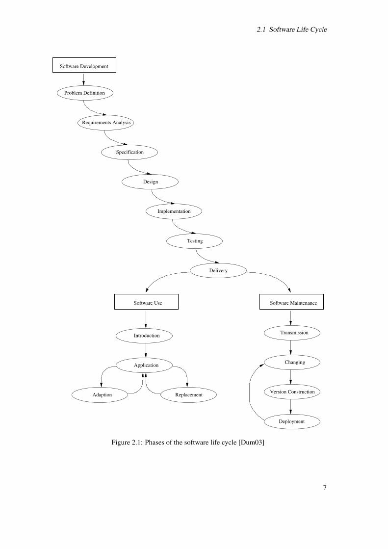
The software life cycle itself is seen as a process to develop software from the first step to the finalrunning product and its maintenance up to its replacement. Figure 2.1 shows an overview of differentphases of the software life cycle. Due to the focus of this work software use and maintenanceare just mentioned. For more details about these phases can be found in the correspondingliterature [Bel00, Dum03, Pre01, Som01].
2.1.1 Problem Definition
The first phase of the software development life cycle is the problem definition. [Dum03] Inmost cases it starts with the order of a customer for a certain software. That means that a strongcommunication between customer and developer takes place to work out a brief description aboutthe product. The client gives his wishes about the software to the software engineer in an informalway, mainly text documents. From this the requirements are derived.
Before going on, it has to be mentioned that the term requirement is not used throughout thesoftware industry consistently. In this paper it is understood as the a property to be met or a serviceto be provided by a system [KPRR06]. To take a closer look at the requirements the categories areused as they are published in [Dum03]. The book separates:
Functional Requirements pool all functions expected from the system. Furthermore informationabout interfaces to other tools or the user are given, as well as information about input oroutput data the system has to work with or to produce. Ideally developer and client togetherdevise significant use cases, so that both sides clearly understand what the system should do.
Quality Requirements include all goals of quality the software should meet or quality standardsto follow. This could be criteria as usability (ergonomics, documentation, learning effort),reliability (stability, fault tolerance), efficiency (performance, resources, system behaviour),maintainability (testability, readability, changeability) and portability (substitutability, com-patibility).
System Requirements describe possible hard or software technologies to be used in the productor for the process.
Process Requirements eventually define details about project specific topics, such as the timeschedule, milestones, financial resources, and organisational resources, as well as personnelresources.
Other sources use different categories for requirements, e.g., functional and non-functional (withproduct, organisational, ethical) requirements [Som01] or functional and data requirements as wellas constraints (e.g., for cost, hard-,software, delivery date) and guidelines [Bel00]. They are also anadequate way to structure the wishes of a customer.
All structured requirements together are the foundation, to speak as an engineer, on which bothsides agree to go on with the next step of development.
6
2.1 Software Life Cycle
Software Use
Introduction
Application
ReplacementAdaption
Software Maintenance
Transmission
Changing
Version Construction
Deployment
Software Development
Delivery
Implementation
Testing
Design
Specification
Requirements Analysis
Problem Definition
Figure 2.1: Phases of the software life cycle [Dum03]
7

2 Fundamentals of Software Engineering
2.1.2 Requirements Analysis and Specification
The next phase is the requirements analysis and specification. Some literature refers to it require-ments engineering [Pre01, Bel00]. The subject of this phase is the validation of the requirementsregarding their correctness, completeness, conformity, consistency, and feasibility. Also require-ments have to be realistic, need by the customer, verifiable, and traceable.This phase is oftenunderrated, even though it is very important for the success of a development process. For example,a review of completed software projects had shown that 13.1 % failed because of incomplete require-ments and 12.4 % because of insufficient involvement of the customer [Dum03]. The requirementsanalysis adopts some methods and techniques to serve its purpose, for example brainstormingand interviews with the customer. This of course is difficult for web-based applications, becausebrainstorming or interviews with millions yet unknown customers is hard to do. Another techniqueis the systematic elimination of ambiguous terms and the definition of a domain glossary if needed.On the formal site effort estimation methods are used to make statements about costs and timeresources.
After that, or sometimes in parallel, the actual software development begins with the so calledspecification. The earlier defined requirements are transformed into models, which depict thesoftware in its whole functionality. The modelling is the structural, operational and informaltransformation of requirements in a form, so that the result is easy to understand and interpretlikewise for developer and client. The structural modelling is the abstraction and partitioning ofrequirements, but without the loose of information. The operational modelling is based on computeraided methods like simulation or animation. Interviews, analysis and investigations are the methodsof informal modelling. Sometimes layouts for the user interface are drawn or a first flat prototypeis implemented to clear details of the system. However, all kinds of modelling aim to a globalconceptual model representing the system. In most cases different types of models are used in aconsistent relation to each other to handle the complexity of a product (e.g., function model, datamodel, state model, work-flow model). [Dum03]
Beside this the specification should describe scenarios for testing of units, modules, the completesystem, and its acceptance. Also a concept for the technical and user documentation should beformalised inhere [Som01].
To summarise, the specification is the complete and detailed definition of the functional andsome quality requirements in form of models. It does yet not include the system requirements.
It has to be emphasised that under some conditions the design is directly following the require-ments analysis. This makes sense whenever a system is very simple or heavily bound to a certainarchitecture [Dum03]. Web-based applications often show the characteristic that a legacy systemhas to be integrated in the new product. In this case the work of detailing should be shifted to thedesign phase, because of its influence to the new architecture [KPRR06].
2.1.3 Design
In the design phase all models from the specification are converted to an architecture, which takes thesystem requirements into account. One differentiates between product implementation requirements,coming from the problem definition (Section 2.1.1) and predefined platform conditions, whicheffect the design of a particular system architecture [Dum03].
The designed architecture contains the structure of the system or its components (also referred asmodules) and their interfaces as well as its relations and interactions with each other. A componentis a encapsulation of functions. In some projects components are an already existing software (so
8

2.1 Software Life Cycle
called legacy system) to add to the new system (e.g. a new system working together with acommercial database). Thereby the integration of these external components ranges from simpleinteraction via an interface to complete embedding. In general, interfaces should connect themodules and hide the internal structure, but this is not always practicable, because of efficiencyreasons.
Once the components and their relations are modelled in an hierarchical way, a decision about acertain design technique to be followed can be mad. Typical methodical approaches to reach a highquality design are Top Down, Bottom Up, Hardest First or Trail and Error.
The act of design itself is done by semi-formal or formal methods. A various number of suchmethods, like Structured Programming, Flow Charts, Function Charts, Event Chart, Pseudo Code,Petri Nets, Semantic Object Model, Architecture of Integrated Information Systems or the UML (seeSection 2.2) exists and are supported by an even higher number of tools, the so called ComputerAided Software Engineering (CASE)-tools. Some of the methods are already in use during thephase of specification (Section 2.1.2). To describe them all would go far beyond the scope of thiswork. Therefore the reader is referred to the appropriate sources (except for the UML because of itsapplication within the development project as part of this thesis).
As result of the design the developer should be able to implement the system directly out ofthe documents generated during this phase. Further, more detailed test cases as well as user anddevelopment documentation should also be part of the output. [Bel00]
2.1.4 Implementation
The phase of implementation follows after the design. As its result a runnable software system iscoded. To do so basically four techniques exists [Dum03]:
• Editing is the manual writing of source code for a software, mainly by the support of aneditor or a development environment.
• Generating means the computer aided form of code production. It is a time reducingprocedure, but only if the design is sufficient enough. Of course, an adequate code generatoris required too. In general the so called templates are generated as a body, in which the finalcode will be edited.
• Adapting is a technique where an already existing code is more or less modified.
• The Reuse is the unmodified adoption of existing source code. This method, of course,requires a fundamental knowledge and understanding of the original code. Reuse is oftendone in form of the usage of source code libraries, which provide solutions for commonproblems.
The developer should follow coding style guides as well as naming, structuring and commentingconventions to ensure the quality of the product.
Another part of the implementation is the testing of the software, to ensure that it is free offaults, errors and failure (even though all three terms have a different meaning they are equallyused in here), if that is achievable at all [Som01, Dum03]. Of course, the correction should be on aminimum, because faults are avoided since the problem definition.
The testing is separated into two kinds of test methods:
Static Program Testing are all methods, which directly validate the source code of a pro-gram (e.g., check lists, reviews or symbolic execution).
9

2 Fundamentals of Software Engineering
Dynamic Program Testing are all methods, which validate the code in its executable form on acomputer. An example of such a test is the so called black-box testing. Thereby the programis treated as a closed unit. It is analysed only by input and the resulting output. Due to thehigh range of possible input values, the analysis is done with a small set of significant values:
• normal values (occurring during a “normal” use of the software)• extreme values (values on an edge of the range, but still valid)• invalid values (values that should not be accepted by the program itself, e.g. character
for a required integer).
Another example is a validation method named white-box test (alias glass-box or clear-boxtesting). This is an approach where tests of usually small units are derived from knowledgeof the software’s structure. The knowledge is used to find out how many test cases are neededto guarantee that all statements of the unit are executed at least once during the test. [Som01]Now, that the units and components are tested, they have to be integrated into a whole andthen tested again. Therefor the grey-box test, a mixture of black- and white-box testing, isa common approach that validates components as well as the system as a whole [Dum03].Depending of the component’s hierarchy the test can be either top-down or bottom-up. If allcomponents are tested at the same time it would be a big-bang test. Once the integration testsare finished it is recommended to test the user interface and the performance behaviour. Thestress testing is a stepwise exceeding of the boundaries set in the requirements (Section 2.1.1)or design (Section 2.1.3). For example a system is designed for 100 transactions per second.With the stress testing one figures out how it behaves in case of 110, 120 and so on. Doingso can identify problems that would have been left undiscovered during normal use. This isespecially important for Web-based systems, because of their uncertain and unstable numberof users. [KPRR06]
The use of software metrics can provide additional information about the quality of the system. Itis a too extensive and too complex topic to go into details here, hence it is just mentioned (for moreinformation see [Bel00, Dum03, Pre01, Som01]).
As part of finishing the implementation a complete user and developer documentation has to bewritten.
2.1.5 Acceptance Testing
The phase after the implementation is the acceptance testing, which simulates the usage of thejust implemented system under real conditions to proof the matching of the costumers require-ments. This is done with or under supervision of the client. Incorrect or incomplete implementedrequirements are listed and revised. [Dum03]
2.1.6 Deployment
The revised software will then be deployed or delivered to the costumer in a final version. Sometimesit is also installed as part of the provided service.
In many cases client and developer agree on a contract of maintenance or future cooperation.This leads to the phases of software life cycle use and maintenance as shown in Figure 2.1. Asmentioned before they are not the centre of interests of this work and therefore left out of furtherdiscussions, even though they are quit important in commercial software development projects.
10

2.1 Software Life Cycle
Problem Definition
Requirements Analysis
Specification
Design
Implementation
Testing
Delivering
Operation and maintenance
Figure 2.2: Waterfall Model [Som01]
2.1.7 Life Cycle Models
The introduction above gives the phases of development one by one, but one can think of a variousnumber of scenarios, in which phases are applied in different orders. The long term experience ofsoftware engineering in praxis teaches that several models of the software life cycle exists [Dum03].This section gives an overview about some of the most common ones.
Two groups can be distinguished which contain themselves a number of models:
Sequential life cycle models are typically following the phases step by step. Examples are theWaterfall Model, the V-Model or the Clean-Room Engineering. They all clearly separate thephases from each other. [Dum03]
Non-sequential life cycle models have the characteristic that they are cyclic. They allow thedeveloper to go more or less back in between the phases. Examples are evolutionarydevelopment with Prototyping or the Spiral Model, incremental development with the theWhirlpool Model or the Fountain Model. [Dum03, Pre01]
The Waterfall Model (Figure 2.2) is a good example for a sequential model. It was one of thefirst models in software engineering. Only if a phase is complete it is allowed to start the next one.The end of each step marks a document on which the next one builds. That is why the WaterfallModel is often referred as a document driven model [Som01]. If errors or faults are detected inthe progress a single step back to the previous phase is allowed to correct them. Every know andthen it can happen that a single step back is not enough to eliminate an error. In this case a wholenew process must be initialised to develop a bedder new version. But this is not intended in theWaterfall Model. This conflict is by far the biggest weakness of sequential models in general.
11

2 Fundamentals of Software Engineering
Problem Definition
Requirements Analysis
Design
Testing
Implementation
Specification
Version IIVersion I
Figure 2.3: Incremental software development [Dum03]
The possibility of such complete renewing is the intention of non-sequential models. Figure 2.3shows the technique of incremental software development. At its beginning all requirements aredefined and modelled, but not all of them are implemented. At first some features are programmed.This early version will then delivered to the client. The lessons learned from its usage have aninfluence on the process and on the next version, which implements additional features. This willbe iterated until a satisfying product level is reached. The incremental model enable the engineerto concretise fuzzy or unknown requirements stepwise. Another advantage is that every iterationproduces a runnable product. The client can use this and instead of long waiting time he getssomething in short periods.
An analogue technique is the Prototyping that also belongs to the group of non-sequential models.The improvement of the cooperation between client and costumer is a major goal of this approach.Therefore it is shortening the time of iterations to a minimum [Dum03]. There is a distinctionbetween:
• Horizontal Prototyping – implements all required functions, but only in an adumbratedway (e.g. the layout of the user interface without its functionality).
• Vertical Prototyping – completely implements some chosen required function (e.g. the useraccount management component is fully detailed and ready to use, but user interface doesnot yet exist).
In both cases the client devises his requirements, then the developer quickly implements a prototypereflecting how he has interpreted the requirements. Afterwards both sides analyse and validate theresult together and implement the improvements into the upcoming version. A prototype can eitherbe used to receive perception about the feasibility (explorative Prototyping) or as an experimental
12

2.2 Unified Modelling Language (UML)
Design
Testing
Implementation
Analysis/Specification
Prototype
Maintenance
Problem Definition
Figure 2.4: Software development as Prototyping [Dum03]
prototype. Thereby the prototype has the role of a template to design and implement the finalproduct. The Figure 2.4 illustrates this process.
In many cases web-based systems are developed by applying some kind of prototyping. Theyoften heavily rely on their look and this is easy to implement and to present to the client [KMP+04].However, all of the software life cycle models have their pros and cons. It remains in the hands ofthe developer to select an appropriate way to fulfil the customer’s needs and wishes.
2.2 Unified Modelling Language (UML)
Section 2.1 alludes from time to time the modelling of requirements or the system. Especiallyduring the design phase (see section 2.1.3) models play an important role. But it is not explainedhow methods to model a system actually work. This section will explain the modelling, usingthe Unified Modelling Language (UML) as an example. Though over the past decades a variousnumber of methods for modelling were invented and implemented in an even higher number oftools, UML is the most widespread one [Dum03].
“. . . UML which is emerging as a standard modelling language, particularly for object-oriented modelling.” [Som01, p. 150]
Hence it is used for modelling the system within the development project, which is subject of thisthesis.
UML is a graphical language for describing object-oriented models. In 1997 it was released inits first official Version 1.0. Reputable organisations as Microsoft, Oracle, IBM, Rational Software,were involved in this release which united the work of Grady Booch, Jim Rumbaugh and Ivar Jacob-sen. They tried to create a unified approach and notation to model software development. [Kec05]
Since 1999 the Object Management Group (OMG) as standardisation committee is responsiblefor the UML and declared it as an official industrial standard. Since that time the UML has beenevolved. This has lead to the current version 2.0 released in 2004. The version 2.0 provides 13
13

2 Fundamentals of Software Engineering
Diagram
Structure
Diagram
Diagram
Package
Diagram
DeploymentComposite
Structure
Diagram
Diagram
Object
Diagram
Component
Diagram
Class Use Case
Diagram Diagram
State Machine
Diagram
Activity
Behavior
Diagram
Diagram
Interaction
Diagram
SequenceInteraction
Overview
Diagram
Diagram
Communication
Diagram
Timing
Figure 2.5: UML 2.0 diagram types
types of diagrams (Figure 2.5). They are distinguished by static (the group of structure diagrams)and dynamic (the group of behaviour diagrams) characteristics. Some of these diagrams will bebriefly explained below. Due to the complexity of the UML specification [Obj05], and thus theUML itself, this can only serve as an introduction to enable the reader to understand the basicconcepts.
2.2.1 Use Case Diagram
The Use Case Diagram (Figure 2.6) provides the means to describe of the system functions inan abstract way. Thus it is used to capture a general vision on a system from a clients point ofview. With its help the requirements are modelled in the phase of Problem Definition regardlessany technical solution (e.g., particular programing language). The following enumeration lists theelements of the diagram.
• Actor – is an object interacting with the system (subject).
• Association – is a relation between an actor and a use case.
• Extend – is a relationship from an extending use case to an extended one, which specifies howand when the behaviour defined in the extending use case can be inserted into the behaviourdefined in the extended use case.
• Include – is a relationship which defines that a use case contains the behaviour defined inanother use case.
• System name – is apparently the name of the system.
14

2.2 Unified Modelling Language (UML)
driver
car driving
car parking
speed control
use case system boundarysystem name
extend relation
include relation
<<include>>
<<extend>>
actor
car simulator
association
Figure 2.6: Example of an Use Case Diagram [Obj05]
• System boundary – marks the border of a system.
• Use case – is the specification of a set of actions performed by a system, which yields anobservable result that is, typically, of value for one or more actors or other stakeholder of thesystem [Obj05].
As an example a very simple simulator for driving a car is used in Figure 2.6. It is easy to realisethat the driver is the actor, who is interacting (association) with the simulator (system) by executingthe “car driving”-use case. This use case includes the use case “speed control”. Thereby it ismeant that driving always and completely encloses controlling the speed. Of course one couldargue that steering the way in which the car is driving would also be a use case while driving. It isright, but may be in this simulator the speed is also influenced by external effects (e.g., lading orweather) other than the direction of the vehicle. Hence the speed control is a little more laboriousto implement. That is why it is explicitly modelled. On the other side parking is a special situationonly occurring at the end of a ride. So, if the car is about to be left, it has to be parked. Thereforethe “car parking”-use case extends the driving.
The example shows that a Use Case Diagram gives an impression of what the system basicallyshall do, without going into detail how. This helps the user and the developer to validate if therequirements are correctly understood.
2.2.2 Class Diagram
As a structure diagram the Class Diagram describes static aspects of a system. It gives infor-mation about the classes (mainly objects in a object-oriented context), types and their relation-ships. Depending on the software life cycle phase it contains platform specific details (Design) ornot (Specification). The example in Figure 2.7 shows the basic elements as given in [Obj05] whichare:
• Class – defines a set of objects that share the same features, constrains and semantics. Aclass has a name and can possess a set of attributes and operations.
15

2 Fundamentals of Software Engineering
Figure 2.7: Example of a Class Diagram
16

2.2 Unified Modelling Language (UML)
• Interface – represents a set of public features that are coherent to the ones realised in anobject. Hence an interface is an abstract connection point to a class or with the words of theOMG
“An interface specifies a contract; any instance of a classifier that realizes theinterface must fulfil that contract.” [Obj05, p. 82]
• Package – is a collection of elements to group them in a structured way. A package alsoprovides a name space for these elements.
• Stereotype – extends the existing elements or type of the meta model to classify and, ifdesired, define a new general element. This is sometimes necessary to meet requirements fora certain programming language.
• Association – describes a semantic relationship between objects. Thereby the name, the roleof each object, or the cardinality (also known as multiplicity) can be specified in form of textalongside the object connecting dash. The addition of these information is also possible forthe specialised association types Aggregation and Composition.
• Aggregation – defines a relationship between objects in the kind of “part of a whole” or inthe other direction “made of”. This means that an aggregated class has instances of otherclasses as part of its own instance.
• Composition – is a stronger kind of aggregation, because unlike the parts of an aggregationthe ones of a composition only exists together with the whole and not as an object itself.
• Generalisation – names the relationship of objects in the sense of inheritance. Each instanceof the specific object is also an indirect instance of the general object. Thus, the specificobject completely inherits the features of the more general object. If this object is abstractthe inheriting object has to implement the abstraction.
• Realisation – describes an abstraction relationship of two elements, one representing aspecification (the supplier) and the other represents an implementation of the latter (theclient).
The example (Figure 2.7 depicts a package “car” with a class of the same name as its centralpiece. Car is also the name of the interface realised by the class. The car consists of an engineand at least four but at most six wheels. This is modelled using the “has a” aggregation. Furtherthe class is marked as abstract through the italic style in which the name is written, because caris a generalisation of a bus and a truck. Hence “truck” and “bus” inherit the attributes (cartype,max. speed, speed) and the operations (accelerate, stop), but may implement them differently.Moreover, they add their own attributes and operation. In addition “truck” has a compositionrelationship to one or more goals which means that a truck contains one or more instances ofdestinations. It is a composition, because it is assumed no destination exists without a truck to gothere (from the system view). The “driver” is associated with the “car” which simply says that oneof them can instance the other. Due to the exemplary character only tree classes are modelled withattributes and operations.
Once again, this example claims neither to be complete nor ingenious, but should transmit how aClass Diagrams are modelled.
17

2 Fundamentals of Software Engineering
Figure 2.8: Example of an Activity Diagram
2.2.3 Activity Diagram
The Activity Diagram describes the sequence and conditions for the behaviour of a system or oneof its parts on a detailed level. All activities are referring to either an use case or a class. Accordingto [Obj05] its main elements are:
• Action – is the function unit within the activity or data flow from edges to other edges. Anaction will execute if all its conditions are satisfied. The completion of an action may enablethe execution of other actions. Such successors use the output for their input. An action has aname and optional pre or post conditions.
• Decision node – is a control node which chooses between outgoing flows. It has one incomingand at least two outgoing edges. The opposite of it is a merge node which has several alternateincoming flows and one outgoing. It is not used for synchronising but for selecting oneamong the alternate flows. Both type of nodes react on conditions that specify the decision.
• End node – marks the final node that terminates a flow.
• Flow – means both object (data) and activity flow. The first describes the way of objectsthrough an activity. The latter depicts its procedural chain.
• Fork node – is a control node that splits a flow into multiple concurrent flows.
18
2.2 Unified Modelling Language (UML)
• Initial node – marks a node at which an invoked activity starts a flow. It is possible that anactivity has more than one initial node.
• Join node – synchronises multiple flows into one.
• Object – is a particular class instance available or required at a particular point in the flow.Beside a name objects can possess additional values such as their state.
Figure 2.8 is a simple example of an Activity Diagram. Therein an instance of the driver classfrom the Class Diagram in Figure 2.7 starts the car after the activity has been initialised. Aftersplitting the activity flow two parallel actions follow, the controlling of where the car goes by the“controlWay” action and the “accelerate” action. As long as the place where the driver currentlyis equals not the destination, he keeps driving. Analogous for the acceleration, if the speed is notproper he keeps adapting it either by positive or negative acceleration. At the moment he arrives athis destination with the right speed he will stop and change his landing, which also terminates theactivity.
Activity Diagrams are much more at the level of algorithm and thus mainly used in the designphase. Often the textual syntax of the diagrams elements equals the one of the programminglanguage chosen for the succeeding implementation [Kec05].
2.2.4 State Machine Diagram
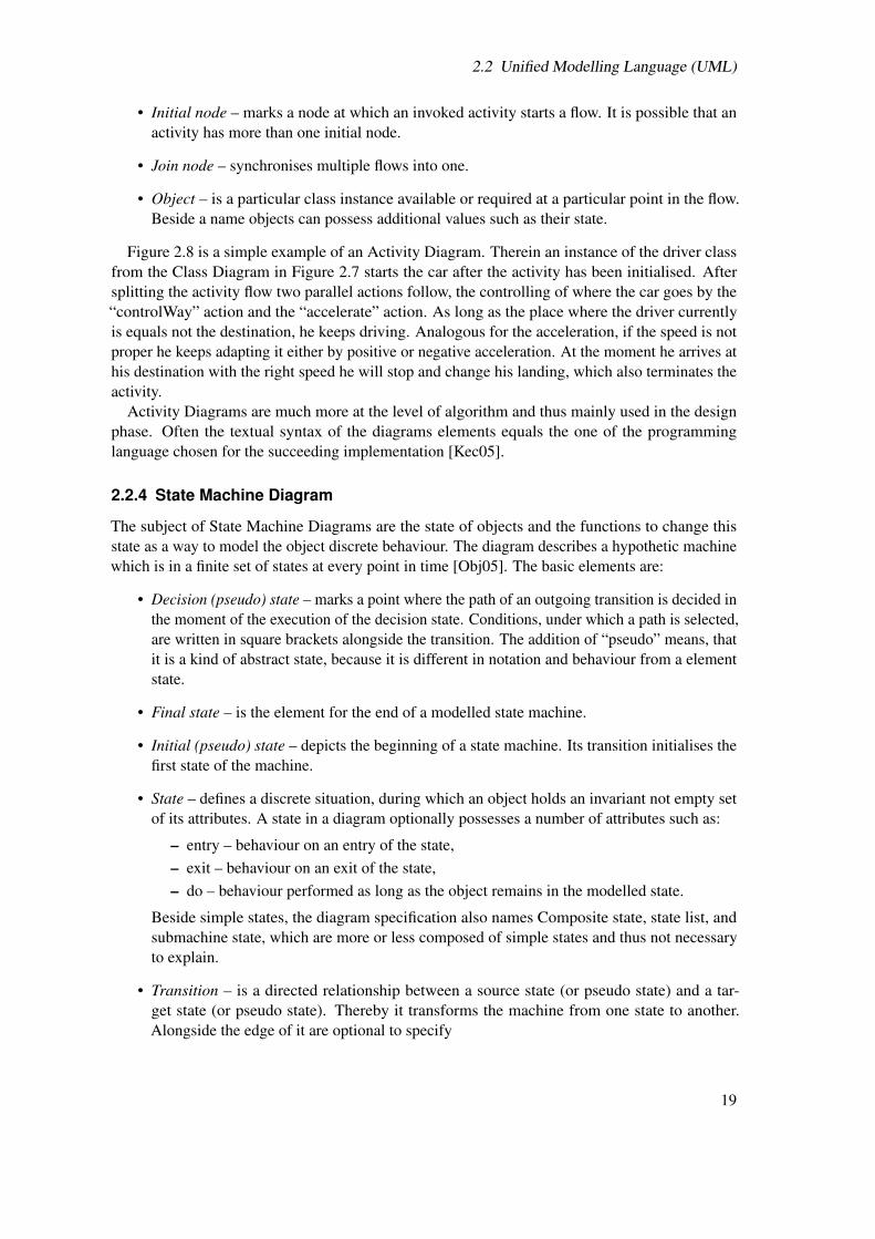
The subject of State Machine Diagrams are the state of objects and the functions to change thisstate as a way to model the object discrete behaviour. The diagram describes a hypothetic machinewhich is in a finite set of states at every point in time [Obj05]. The basic elements are:
• Decision (pseudo) state – marks a point where the path of an outgoing transition is decided inthe moment of the execution of the decision state. Conditions, under which a path is selected,are written in square brackets alongside the transition. The addition of “pseudo” means, thatit is a kind of abstract state, because it is different in notation and behaviour from a elementstate.
• Final state – is the element for the end of a modelled state machine.
• Initial (pseudo) state – depicts the beginning of a state machine. Its transition initialises thefirst state of the machine.
• State – defines a discrete situation, during which an object holds an invariant not empty setof its attributes. A state in a diagram optionally possesses a number of attributes such as:
– entry – behaviour on an entry of the state,– exit – behaviour on an exit of the state,– do – behaviour performed as long as the object remains in the modelled state.
Beside simple states, the diagram specification also names Composite state, state list, andsubmachine state, which are more or less composed of simple states and thus not necessaryto explain.
• Transition – is a directed relationship between a source state (or pseudo state) and a tar-get state (or pseudo state). Thereby it transforms the machine from one state to another.Alongside the edge of it are optional to specify
19

2 Fundamentals of Software Engineering
Figure 2.9: Example of a State Machine Diagram
– trigger – multiple actions that fire the transition,– guard – in square brackets written conditions that control the transitions firing, but in
contrast to decision states without an alternative,– effect – additional behaviour to perform when the transition fires syntactically separated
by a slash after a guard or a trigger.
Most of these elements are shown in the example in Figure 2.9. The state machine there startswith a ready truck. Once the driver has started the car (condition expressed by a guard) the transitionfires with the start car action which leads to the state of a started truck. As to see it performs thebehaviour of driving (do attribute) while the machine remains in this state. Via transition the truckstops if the destination has been reached, then the lading is changed. The transition new ladingeither leads to the final state, in the case that the lading variable of the truck class possesses thevalue empty, or back to the state of a started truck.
As an advantage of state machines counts its formalism, which allows a designer to evaluate amodel or rather a system component in a mathematical way (e.g. testing for deadlocks, reachabilityor liveness). They are used in the specification phase as well as in the design phase, though a moredetailed in the latter. Similar to Activity Diagrams (Section 2.2.3) it is close to the implementationespecially in combination with the syntax of the targeted programming language.
2.2.5 Sequence Diagram
The most common (though with the most complex specification) variant of interaction diagrams isthe Sequence Diagram, which focuses on interactions via messages interchanged between lifelinesof objects [Obj05]. As the name indicates it is sequential and thus time-dependent. In general itdescribes the dynamic intra and inter system communication by using the following elements:
• Action – names which interaction is performed with a message.
• Combined fragment – defines a fragment of interaction, which enables the modeller todescribe a number of traces in a compact and concise manner. The operator specifies the typeof fragment and sometimes has a guard to express when or if the fragment is performed. Theoperator is one of:
20

2.2 Unified Modelling Language (UML)
– alt – for at least two alternative sequences,– assert – for an assertion that must be valid,– break – for a breaking scenario,– consider – for designating which message should be considered within this fragment,– critical – for a fragment that can not be interleaved,– ignore – for indicating that messages are not shown,– loop – for a defined number of iteration,– neg – for negative or invalid defined fragments,– opt – for optional behaviour where either the optional fragment is performed or nothing,– par – for parallel interactions,– seq – for an unordered sequence respectively where the order is undefined,– strict – for a strict sequencing.
• Execution – is a unit of behaviour or action within the lifeline. It is possible to specifyconditions, under which they participate in the interaction or the duration of an execution.
• Interaction use – refers to another interactions.
• Lifeline – represents an individual participant of an Interaction.
• Message – defines a particular communication between lifelines. The different kind ofmessages are
– asynchronous,– found as they are received from a non specified source and are modelled as a small
black circle at the starting end,– lost as they are send to a non specified target and are modelled as a small black circle at
the arrow end,– synchronous with a call and the corresponding reply.
• Sequence – depicts a sequence identified by its name. A Sequence Diagram may containmultiple interacting sequences.
• Termination – marks a termination of a lifetime through using a cross at the lifelines end.
The example in Figure 2.10 shows a sequence of pegging a picture. Therein the participants are aperson, a hammer, a nail which has to be straight by condition, a thump and a picture. Until the nailis in a steady position (condition on the loop) tries the person to pound it with the hammer. Eitherthe hammer hits the nail as intended or the thumb. In the latter the interaction for medical treatmentfor the thumb is performed, but is not further specified and just referred. Once the loop is ended theperson pegs the picture to enjoy it afterwards.This should give an impression how behaviour of asystem is modelled in a Sequence Diagram.
All other members from the group of Interaction diagrams use more or less a similar conceptas the one introduced above. They are focusing more on the exact time (Timing Diagram), objectcommunication (Communication Diagram), or combined interaction overall (Interaction OverviewDiagram). However, they all are used for modelling during the specification and rather the designphase, because of their appropriate representation of how a system is executed or interacts duringexecution.
21

2 Fundamentals of Software Engineering
:picture:thumb:nail:hammer:person
sd peg picture
loop
alt
ref
[straight]
[nail steady]pound
hit = pound
hit
hit
medical treatment for thumb
peg picture
enjoy picture
lifeline conditionsequencesequence name
recursion
reply
combined fragment
asyncronous message execution
interaction use
call
action
operator
Figure 2.10: Example of a Sequence Diagram [Kec05]
22

2.3 Tools Supporting Software Engineering
Table 2.1: Process perspective of CASE tools [Som01]Class of tools for Specification Design Implementation ValidationRe-engineering ×Testing × ×Debugging × ×Program analysis × ×Language-processing × ×Method support × ×Prototyping × ×Configuration management × ×Change management × × × ×Documentation × × × ×Editing × × × ×Planning × × × ×
To summarise this section, the UML is a very powerful, though complex language to supportsoftware development, especially if used with a tool. Such tools usually provide the very supportiveservice of code generation. They are grouped under the term of CASE tools, which is the subject ofthe next section.
2.3 Tools Supporting Software Engineering
The subject of this section is to give an overview about technologies, which support the software lifecycle as described at the beginning of this chapter (see Section 2.1 and aides the development pro-cess. They are accumulated under the expression of Computer-aided Software Engineering CASEtools and include design editors, data dictionaries, compilers, debuggers, system building tools,etc. [Pre01] The advantage of these technologies is their automation of some development processactivities. The use of CASE tools can lead to improvements in software quality and productivity.
“. . . improvement were likely if integrated CASE environments were used. In fact, the ac-tual improvements which have been achieved are of the order of 40 per cent.” [Som01,p. 64]
The CASE technologies can be classified according to the process phase they are specialised for.Table 2.1 presents this classification. CASE tools supporting the early phases up to the designare called upper CASE tools. On the opposite site, lower CASE tools refer to those tools, whichsupport the phases of implementation and testing [Dum03].
Another classification is possible according to how they are integrated to more complex systems,for example:
• Tools – support single process tasks such as compilation, file comparison, code editing, etc.They are mostly stand-alone tools.
• Workbenches – are composed of tools and support phases or activities such as design,validation, etc.
23

2 Fundamentals of Software Engineering
• Environments – support all or at least a substantial part of the development process byintegrating several tools or workbenches into a single system. It is not uncommon for themto feature in some way the possibility to add new functionality via plug-ins.
Especially the last group, also known as Integrated Development Environment (IDE), are essentialfor todays large software development project to be effective. Typical representatives are the EclipsePlatform of the Eclipse Foundation, NetBeans of Sun Microsystems, C++ Builder of Borland, etc.A more extensive list can be found under [Wik06a].
Still software engineering remains a highly creative work, thus these CASE technologies are notsilver bullets to eliminate all difficulties from the development process.
24

3 Fundamentals of Web-Based Applications
The previous chapter gave an overview of software engineering methods. This chapter is aboutunderstanding how Web-based application may look like, respectively their architecture, and whattechnologies are used to implement such architectures. Because of the broadness of the domainof web applications, this part will concentrate on architectures and technologies which are in thescope of this thesis.
3.1 Web Application Architectures
Before describing any architecture it seems to be appropriate to define the term itself. Thoughthere is no unique definition, the author favours the following to give the intention how the term isunderstood within this document:
“The architecture, in the sense of Web application development, is the software orhardware related structure of a system to develop, which contains the componentsof the structure, their extern interfaces and the relationships between the compo-nents.” [DLWZ03, p. 141]
An architecture of a system is primary influenced by the functional and system requirements (e.g.,operating system or integration of legacy systems).
In general, Web applications are a kind of distributed systems. Some of these distributed systemsare based on the client/server model and some are not. The following brief description should givean overview of architectures addressing the distribution of data and messages [KPRR06]:
Peer to Peer (P2P) – describes the direct communication between two participants (the peers)without a server as mediator (e.g., point to point connection) and the way how they discovereach other. Thereby the peers are acting equally. Examples include JXTA and Xmiddle.
Distributed Object Middleware (DOM) – is an infrastructure to access remote objects transpar-ently. It is based on the Remote Procedure Call (RPC) mechanism. Some systems un-der DOM also enable objects to interact beyond their own boundaries with different plat-forms, e.g., Common Object Request Broker Architecture (CORBA). Further examplesinclude Microsoft’s Distributed Component Object Model (DCOM) or Sun Microsystems’Enterprise Java Beans (EJB).
Virtual Shared Memory (VSM) – is a technique in which distributed processes access commondata. Thereby an appropriate middleware is used to allocate the data, which can be stored“anywhere”. Examples of VSM systems are Corso and Equip.
Message Oriented Middleware (MOM) – offers functionality for communication via asyn-chronous messaging, which means that the transmission is sent to the receiver regardless ofits status. In the case of an unavailable participant MOM ensures that messages are deliverednevertheless. For instance, the Java Messaging Service (JMS) and the Microsoft MessageQueue (MSMQ) represent MOM.
25

3 Fundamentals of Web-Based Applications
Service Oriented Middleware (SOM) – enhances DOM by the idea of services. In this context itmeans that a number of objects and their behaviour are made available for other by usinga well defined interface. SOM specifies communication protocols between services andprovides location- and migration-transparent access to them. Thus it is an approach thatovercomes boundaries of platforms. All architectures that emerged within the field of Webservices belong to the SOM group. One example of a SOM is Sun’s Jini system.
As mentioned above these architectures principally belong to distributed systems and are notlimited to Web-based applications. This is why they are not discussed in detail. Even though someof them are based on the client/server model, the focus is moreover on the common and widelysuccessful approaches of client/server architectures for Web applications. They will be the subjectof the next section.
3.1.1 Client/Server Architecture
The concept of this architecture is the separation of system components in two roles based on therequest-response principle [Som01]:
Client is a piece of software that sends a request for a particular service to a component.
Server is a piece of software that implements a certain functionality and responds to a requestregarding this functionality.
Within the client/server architecture one can distinguish between architecture types based on thepoint where the client is connected to the server and the following layers [DLWZ03]:
• Presentation – to present the data,
• System control – to control the workflow of the system,
• Application control – to exchange and prepare data,
• Data management – to provide functions to access the database,
• Database – to store and manage the data,
The Figure 3.1 illustrates the different types. Thereby the network separates the client’s functional-ity (all units above the network) from the server’s (all units below the network). One speaks of athin client system if just the presentation layer is implemented by the client and of a fat client in thecase, in which the client additionally prepares data or controls the workflow.
3.1.2 Two-Tier Architecture
A client/server architecture consisting of a single server and at least one client is depicted as two-tierarchitecture. Thereby the network strictly divides the layers of the client from those of the server.The whole interaction takes place through the network, like Figure 3.2 shows. The server includesall necessary functionality, such as database management, application and system control (BusinessLogic). [KPRR06]
Thus the two-tier architecture is suitable particularly for simple Web applications. Maintainingthe server may become a difficult and complex burden once the application reaches a certain levelwith a higher number of components.
26

3.1 Web Application Architectures
Figure 3.1: Types of client/server architecture [DLWZ03]
Network
Client
Client tier
Web Server and
business logic
Database
Services
Dynamic HTML−
pagesStatic HTML−
pages
Server tier
Figure 3.2: Example of a two-tier architecture [KPRR06]
27

3 Fundamentals of Web-Based Applications
3.1.3 N-Tier Architecture
In Contrast, the N-tier architectural approach is more suitable for larger applications with complexbusiness logic, which are accessed by a large number of concurrent clients. The application isorganised in an arbitrary number of layers, typically the following three. [KPRR06]:
• Presentation tier – renders the result of a request in the demanded output format.
• Business tier – hosts the business logic of an application in an application server. It providesthe workflow, the data access, the connection to legacy systems, etc.
• Data tier – contains the data and its management, usually a database server with a databaseand a database management system.
Additionally, mechanisms for the security (e.g. firewalls) or for the caching (e.g., proxies) can beintegrated into the request-response flow if needed. Note that the term tier and layer as well asN-tier and three-tier (N-tier and three tier divide the business tier into several layers) are often usedsynonymously.
The main difference between two- and N-tier architecture is how the latter embeds functionalitywithin the application server component. To make services available to all Web applications theyare held in the application server context. For instance, services like customisation respectivelypersonalisation might be used by various Web applications. As another advantage counts that three-tier architectures profit from the load balancing mechanisms of applications servers. Further, socalled connectors are available to integrate external applications or legacy systems. The Figure 3.3illustrates the N-tier architecture and its components. The N-tier architecture is more complex todesign, because of the difficulties to reach a clear separation of the layers.
The described advantages of the three-tier over the two-tier architecture led to its success in largeWeb-based applications and it is not surprising that a lot of application servers are based on thisarchitecture (e.g., J2EE, WebSphere, .NET). [KPRR06] Some might wonder if there is a three-and a two-tier architecture exists there also a one-tier approach. It exists but the special case of aone-tier architecture, also known as host/terminal system, will not be discussed herein. It is notconsidered as a client/server system, because the terminal is a simple input/output device withoutown memory and processor capacity. A terminal is not requesting a service. All workload is doneby a monolithic host.
3.2 A Closer Look at the N-Tier Architecture
Due to the relevance of the N-tier architecture for this thesis a more detailed look at its layers and thecorresponding implementation technologies will be given in the following. It has to be emphasisedthat the topic contains an uncounted number of different technologies, pattern, frameworks, etc., ofwhich only a small set will be presented. Of course, the introduced technologies are not exclusiveto a N-tier architecture. In fact, some of them have been developed completely independent fromthe Web. This is the case for technologies in the data tier.
3.2.1 Data Tier
Since the mid 1960’s the efficient and structured storage of large data sets is the domain of databases.The development of relational databases, SQL and Entity-Relationship (ER) in the years from 1970
28

3.2 A Closer Look at the N-Tier Architecture
Web Server
Presentation tier
Client
Firewall
Proxy
Business tier
Database Server
Data tier
Data access Connectors
Workflow Personalization
Business logic
Application Server
External
application
Legacy−
system
Backend
Figure 3.3: N-tier architecture [KPRR06]
to 1975 signify undisputed one of the most successful and long living technologies in the historyof software [HS97]. Thus database systems are the leading technology to manage data in a Webapplication.
It turns out that the vast majority of the world’s corporate data is now stored inrelational databases. They are the starting point for every enterprise application witha lifespan that may continue long after the application has faded away. [KS06, p. 1]
It must be admitted that content management systems are moreover used to manage documentsand the whole Internet presence (e.g. layout, configuration, site mapping, versioning, etc.) than thatthey handle single data [DLWZ03, KPRR06].
According to [CFMS95, p. 3]:
“A database is a collection of mutually correlated data permanently stored on per-sistent storage supports. . . . In a database, data (entities) and entity associationsthat characterise an organisation are described. Data management functions, usuallysupplied by an operating system, are extended through a set of programs globallycalled the Database Management System (DBMS). Great quantities of data can beaccessed rapidly and efficiently by a DBMS, which supplies a set of targeted functions,such as schema management, concurrent transaction management, data access control,logging, recovery of the database after system failures.”
The definition also sorts the term Database Management System (DBMS), which builds togetherwith the database the Database System (DBS) [SST97].
29

3 Fundamentals of Web-Based Applications
attributevalue
A 1 A n. . .
. . .
. . .
. . .
} relation schema
relation
tuple
attributerelation name
R
Figure 3.4: Terms of the relation model [SST97]
Since databases became state of the art for the data tier in applications this section will introducethe fundamentals without giving a complete formalisation.
Relational Database Model
The relation database model is based on organising data in form of tables (relation). Thereby thefollowing expressions (see Figure 3.4) describe a relation.
• Attribute – is a column of a table and by that a name a set of values values.
• Attribute value – is a cell of a table, thus an atomic value.
• Relation – is the table containing of a set of tuples.
• Relation name – names a table.
• Relation schema – describes the structure of a relation by its attributes.
• Tuple – depicts a row of a table and is a set of attribute values (It is required that tuples areunique within a relation).
The uniqueness of a tuple is also referred as the key and is part of the integrity ensuring [HS97].One differs into
Primary key , which names a attribute or a attribute combination to identify every single tuple ofa relation; and into
Foreign key which is a reference to a primary key of another relation or sometimes the samerelation.
One may notice the similarity to an algebra. This results from the formal way, in which therelation model relies, the so called relational algebra.
The relational algebra enables a flexible, independent modelling by providing a variety ofoperations and queries that are not bound to the underlying physical features. It formalises therelation schema R as a set attributes (A1,A2, . . . ,An):
R = {A1,A2, . . . ,An}
It formalises the relation (r) as a set of n-tuples (a1,a2, . . . ,an).
r = {a1,a2, . . . ,an} with a1 ∈ A1,a2 ∈ A2, . . . ,an ∈ An
30

3.2 A Closer Look at the N-Tier Architecture
As an algebra it provides a number of operators, all applying on relations and giving relations asresult. The main operators on sets of the relational algebra are (assuming the two relations r and s):
• Union – applied to r and s, returns a new relation t defined as a set of n-tuples belonging to ror to s:
t = r∪ s
• Difference – applied to r and s, returns a new relation t defined as a set of n-tuples belongingto r and not to s:
t = r− s
• Intersection – applied to r and s, returns a new relation t defined as a set of n-tuples explicitlybelonging to r and to s:
t = r∩ s
• Cartesian product – applied to r and s, returns a new relation t defined as a set of n-tuplesthat are a combination of the k-tuples of r and the m-tuples of s:
t = r× s with n = k ∗m
• Projection – applied to r, returns a new relation s containing the n-tuple of r defined on asubset of attributes of r. It implements the vertical decomposition of r:
πattribute 1,...,attribute n (r) = s = {attribute 1, . . . ,attribute n} , s⊆ r
• Selection – applied to r, returns a new relation s formed of the n-tuple of r verifying apredicate on a subset of attributes of r. The predicate is expressed through a formulainvolving constants, attributes, and comparison operators (one of <, ≤, ≥, >, =, 6=). Alsopredicates can be combined by connectors (one of ¬, ∧, ∨). The selection implements thehorizontal decomposition of r:
σpredicate ⊕ ... ⊕ predicate (r) = s with ⊕ ∈ {¬,∧,∨}and
predicate = attribute ⊗ constant with ⊗ ∈ {<,≤,≥,>,=, 6=}
• Natural join – applied to the relations r (with the attributes A and B) and s (with the attributesB and C), such that AB intersected with BC results C, returns a new relation t defined on theattributes ABC. The relation t consists of the set of n-tuples resulting from the concatenationof k-tuples in r with the m-tuples in s that have identical values for the attribute C:
r ./ s = t with AB(r) ∩ BC (s) = B
It is also possible to use predicates in a join. A join, in which the intersection is an empty set,becomes a Cartesian product.
• Renaming applied to the relation r renames an attribute A to A′. It is necessary, because ajoin requires equal names of an attribute to be executed:
βA′←A (r)
31

3 Fundamentals of Web-Based Applications
One can imagine that such algebra is implemented in a various number of query lan-guages (e.g. SQL, Query By Example (QBE), and QUEry Language (QUEL)). The SQL marks oneof the most important. It is by far the most widespread [SST97] and will be introduced in the follow-ing. Though it is neither intended nor possible to cover the complete standard. For more informationabout SQL the reader is referred to the appropriate sources (e.g. [SQL06, Pos07, HS97]).
SQL allows the definition of tables with its attributes and the corresponding data type. It isalso possible to define a primary and additional foreign keys. This short example should give animagination of the syntax to define data:
1 CREATE TABLE table_12 ( attribute_1 integer,3 attribute_2 varchar NOT NULL,4 attribute_3 date5 PRIMARY KEY (attribute_1),6 FOREIGN KEY (attribute_2)7 REFERENCE another_table (another_attribute) )
The command NOT NULL forces defined values in every tuple of this attribute. This also indicatesthat every data type contains an undefined value symbolised by NULL. SQL enables a alternation oftables through the ALTER TABLE-command. For example, it supports the renaming of a column,the change of number of columns, the change of referential integrity, etc. The DROP-commanddrops tables, column, etc.
Beside the definition of relational databases, SQL supports the querying for data. Thereby thebasic concept is the so called SELECT-FROM-WHERE-block [Pos07, SQL06], short SFW-block.It is a statement to query a database. The single parts of the block mean:
• SELECT – specifies the column(s) of a table.
• FROM – specifies the relation(s) to which the block is applied.
• WHERE – specifies the condition, which has to be valid to select a tuple.
A statement without a WHERE-clause is analogous to the projection in relational algebra. TheWHERE-clause itself would represent a predicate in relational algebra. The clause may also involveseveral encapsulated SFW-blocks and other operations such as UNION and EXCEPT (difference).Further it is possible to use the JOIN-command or one of its derivate in the FROM-clause. Theexample below shall illustrate the use of the SFW-block. Therein the column 2 from relation a and4 from relation b are selected if the tuples have the same value in column 1 and 3, and if the valuein column 2 is bigger than the value 5.
1 SELECT table_a.column_2, table_b.column_42 FROM table_a, table_b3 WHERE table_a.column_1 = table_b.column_3 AND table_a.column_2 > 5
The manipulation of data works in a similar way. It uses the commands:
• DELETE – deletes tuples from the specified table. An optional condition in WHERE-clause ispossible to specify certain tuples.
• INSERT – inserts a new tuple or values into the table.
• UPDATE – changes the value of cells, also with an optional WHERE-clause.
32

3.2 A Closer Look at the N-Tier Architecture
works in[0,4]
cardinality relationship entity
primary key
attribute
Employee Office
Identifier
Address
Name Building
Room number
Figure 3.5: Example of an Entity-Relationship-Diagram
Nowadays, SQL is supported in many database systems, e.g., DB2, MySQL, PostgreSQL, Sybase,Informix, Microsoft SQL Server.
To design relational databases the ER-model is a proven technique. It uses a graphical notationto draw an abstract model of the database. The Figure 3.5 shows the diagram and its elements inthe way it is introduced in [HS97, SST97]. It is based on the concept of three main elements:
• Entity – describes an object from the real world or an imagined world, about which informa-tion have to be stored. Entities with common characteristics are grouped under an entity type.The entity type is symbolised with a rectangle.
• Relationship – describes a relationship between entities. It is is symbolised with a rhombusthat is connected to the participating entities. It may posses additional attributes to char-acterise the relationship. Sometimes a cardinality is specified to express the quantity of arelationship.
• Attribute – is a characteristic of an entity or a relationship. It is symbolised with a rectanglewith rounded corners. The underlining of an attribute specifies it as a primary key.
The simple, but very formal, concept of the ER-model is a reason for it’s success. Furthermore,the design via ER-models is supported by many software tools, which generate SQL-commandsfrom the ER-diagrams, and execute them to construct the database.
3.2.2 Business Tier
The business (or logic) tier implements the logic on a server as described above. Therein differentconcepts can be applied to handle the tasks.
For example, the interaction with a relational database system (see Section 3.2.1) is oftenprovided through the use of a standard interface such as:
Open Database Connectivity (ODBC) – is an interface developed by Microsoft to enable theaccess to different databases with SQL-commands without the necessity to change theapplication above. ODBC contains a driver manager, which decouples an application from acertain database driver. The driver manager is responsible for the loading of the appropriatedatabase driver and delegating of all commands towards it. The interface to the drivermanager as well as the one to the database driver follow a well defined specification. [SST97]
33

3 Fundamentals of Web-Based Applications
StAX
PersistenceJava
JTA
Connectors
JMS
Management
WS Metadata
Web Services
JACC
JAXR
JAX−WS
JAX−RPC SA
AJ
JAFMailJava
EJB
EJB Container
Database
StAX
PersistenceJava
JTA
Connectors
JMS
Management
WS Metadata
Web Services
JACC
JAXR
JAX−WS
JAX−RPC
Java Server
Faces
JTSL
SA
AJ
JAFMailJava
Servlet
JSP
Web ContainerClient
Browser
HTTP
SSL
Server
Figure 3.6: Java EE platform APIs [JBC+06]
Java Database Connectivity (JDBC) – is an API from Java with a concept similar to the one ofODBC. It is a standard interface to interact with a SQL-database. Hence it is heavily reliant onthe query language. JDBC allows the use of SQL-statements within a Java program [KS06]by offering an abstract and neutral interface. The different database vendors offer a JDBC-driver for their product. This driver respectively the needed packages are dynamically loadedduring runtime and handled by a driver manager provided by Java. The manager is thenused to control the connections and the interaction with the database. Though using thesame concept as ODBC, JDBC is considered to be easier to handle and to have the betterclearness [SST97].
Java offers also other APIs, which can be used in the business tier. In fact, Java providesa complete specification for Web-based applications, the Java Platform, Enterprise Edition(Java EE) [JBC+06]. It is a specification of a software architecture not a ready to use software.The Figure 3.6 illustrates the Java EE specification Due to the fact that JavaEE is a very extensivespecification only the core components Servlets, Java Server Pages (JSP), and Enterprise JavaBeans (EJB) are introduced in the following:
34

3.2 A Closer Look at the N-Tier Architecture
Servlets – are a component technology designed to serve the needs of Web developers who needto respond to Hypertext Transfer Protocol (HTTP) requests by returning dynamic generatedcontent. They are the complement to the Common Gateway Interface (CGI) in the world ofJava. Servlets are invoked by a special Uniform Resource Locator (URL) to process incomingrequests. The requests are send from the client and forwarded by the server. Then a Servletgenerates Hypertext Markup Language (HTML) response pages on the fly [FC05]. Servletshave to run in a special environment which is fully integrated into the Web server. Thisenvironment is the Servlet (or Web) container. Servlets provide a multi-threading capabilityso they are able to handle many requests concurrently in different threads, though a singlethread is sequentially processed. Thereby the sequential steps are:
1. reading all data from the client,2. looking up the information, which is embedded in the HTTP request,3. generating result, if required through interaction with an other component, database, or
external system,4. putting the results into a document form,5. setting response parameter (e.g. cookies, caching parameter, document type, etc.), and6. sending the result document to the client.
In addition, a large number APIs are available to integrate supplementary of features (e.g.,Java Authentication and Authorisation Service (JAAS), Java Architecture for XML Building(JAXB), JavaMail). [JBC+06] Moreover, Servlets offer an elegant way of session tracking byusing cookies and the HTTP-Session object to access session data [FC05]. Servlets are mainlyused to generate dynamic content, to track the session, and to implement the business logic.Their advantage lies in their procedural style, the clearly encapsulate Java code, whereasthe disadvantages are the complexity coming along with the Java technology and the inertreaction (if the Servlet is very complex through the including of many templates) [FC05].
JSP – are a Java component technology designed to simplify the programming of dynamic,graphical sophisticated HTML pages. They extend the conventional static document withsnippets of Servlet code through special JSP-tags [JBC+06]. It is the attempt to combine thereadability of HTML-tags and the strength of the Java API. Since the JSP specification isbased on the Servlet specification, JSP support within a Web server provides a translationlayer. Individual JSP documents are stored as text files on the server. When the JSP documentis first requested the JSP engine uses the JSP file to generate the source code for a Servlet.The generated code is then compiled, installed into the Servlet engine, and used to service therequest. Once the JSP has been compiled, the compiled version is saved and used for fulfiladditional requests according to the standard Servlet specification [FC05]. This procedureincreases the performance of the request-response process. In case of a modification on theJSP file the server detects this change and rebuilds the corresponding Servlet. Figure 3.7illustrates the JSP processing in a Sequence Diagram. Beside the improvement of thedevelopment of dynamic content, the JSP technology aspires a better separation of functionaland presentational parts of a system by its tags. The tags represent a certain command tothe JSP engine. It is possible to add customer defined tags. Thus, the functionality canbe excluded into the custom tags, which allows the division of labour into designer anddeveloper. The first are responsible for the presentation (e.g. HTML elements for layout,navigation, etc.) through the use of tags, the latter for the business logic (custom tag library).Once a tag library is established, it is much likely that it will be reused in many projects. This
35
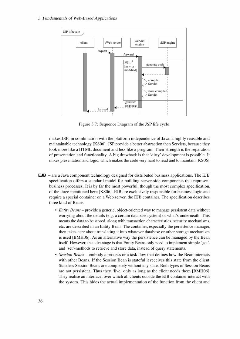
3 Fundamentals of Web-Based Applications
:JSP engine:Servlet
:Web serverengine
:client
JSP lifecycle
[new or
modified]
opt
compile
Servlet
Servlet
store compiled
generate
response
forward
request
generate code
forward
Figure 3.7: Sequence Diagram of the JSP life cycle
makes JSP, in combination with the platform independence of Java, a highly reusable andmaintainable technology [KS06]. JSP provide a better abstraction then Servlets, because theylook more like a HTML document and less like a program. Their strength is the separationof presentation and functionality. A big drawback is that ‘dirty’ development is possible. Itmixes presentation and logic, which makes the code very hard to read and to maintain [KS06].
EJB – are a Java component technology designed for distributed business applications. The EJBspecification offers a standard model for building server-side components that representbusiness processes. It is by far the most powerful, though the most complex specification,of the three mentioned here [KS06]. EJB are exclusively responsible for business logic andrequire a special container on a Web server, the EJB container. The specification describesthree kind of Beans:
• Entity Beans – provide a generic, object-oriented way to manage persistent data withoutworrying about the details (e.g. a certain database system) of what’s underneath. Thismeans the data to be stored, along with transaction characteristics, security mechanisms,etc. are described in an Entity Bean. The container, especially the persistence manager,then takes care about translating it into whatever database or other storage mechanismis used [BMH06]. As an alternative way the persistence can be managed by the Beanitself. However, the advantage is that Entity Beans only need to implement simple ‘get’-and ‘set’-methods to retrieve and store data, instead of query statements.
• Session Beans – embody a process or a task flow that defines how the Bean interactswith other Beans. If the Session Bean is stateful it receives this state from the client.Stateless Session Beans are completely without any state. Both types of Session Beansare not persistent. Thus they ‘live’ only as long as the client needs them [BMH06].They realise an interface, over which all clients outside the EJB container interact withthe system. This hides the actual implementation of the function from the client and
36

3.2 A Closer Look at the N-Tier Architecture
Servlet
JSP/
Web
container
Client Interface
Stateful
Session
Bean
Bean
Entity
EJB
container
4. instance
JNDI
invoke
3. instance and 1. request
5.respond
Server
2. look up
Figure 3.8: Example for the interaction between JSP and EJB
allows different kinds of clients (e.g. Servlets, JSP, stand alone applications, legacysystems, other EJB, etc.) to use the application [KS06].
• Message-Driven Beans (MDB) – process messages asynchronously from systems likethe Java Message Service (JMS), legacy systems, and Web Services. Similar to SessionBeans, MDB coordinate task flows involving other Beans. They differ just in theway they are accessed. They do not use an implemented interface, that defines whichmethods can be invoked, but subscribe to or listen for messages. Thus they handlefunctionality that does not require an immediate response [JBC+06].
Since the EJB3.0 specification, which is used in this work, EJB are simple Java classes andinterfaces. The classes are extended with annotations, which declare a class or interface as aBean. Annotations are a language feature that allows structured and typed meta data to be at-tached directly to the source code. Annotations overcome the onerous handling of additionaldeployment descriptor files, which contain the meta data in earlier EJB specifications. De-ployment descriptors can still be used optionally [KS06]. For example, these meta data carrythe information for an entry in the Java Naming and Directory Interface (JNDI). This entryenables all other Beans or Clients to ‘find’ a certain Bean. Assuming that one has developedand deployed a JSP-site, a Stateful Session Bean, and an Entity Bean on a Java EE-server, aclient may send a request. The JSP site needs the functionality of a Bean to respond. It looksup the needed Bean in the JNDI and contacts the Bean container to use the Bean interfaceto invoke the Session Bean’s functionality. Then the Stateful Session Bean is instanced, sothat the Session is bound to the client. Since the Session Bean implements the logic andworks with Entity Beans, it provides the services to instance an Entity Bean by whethercreating a new one or getting one from a underling data source. Afterwards it executesall required operations so that the JSP is able to respond. Figure 3.8 shows this process.The technology of EJB brings the benefits of a very high level of separation between data,logic, and presentation. The concept of the container is a powerful instrument, especiallyin perspective of load balancing. The container manages the EJB objects and the resources
37

3 Fundamentals of Web-Based Applications
for the Beans, and additionally provides services such as transactions, security, concurrency,and naming at runtime. Once EJB are developed, they can be deployed on any Java EEcompatible server, even redundant on many servers, and will work out of the box [BMH06].Thus, they have a big advantage in scalability and portability. They can bridge the gapbetween relational databases and object-oriented applications via object-relation mapping.Further, EJB provide an excellent way to integrate external tools and legacy systems [FC05].All these positive points go along with the disadvantage of the complexity. One can easilyspend a lot of time to understand and apply EJB correctly. It is also required to use aJava EE compatible server. Today exists a hand full of free servers (e.g. GlassFish from SunMicrosystems, JBoss from JBoss Inc., Geronimo from Apache Software Foundation, JOnASfrom the ObjectWeb consortium, etc.). The maintenance of such a server and therefore theuse of EJB will cause some extra costs. Like any other technology they have their costs andbenefits. EJB should only be used when their benefits outweigh their disadvantages. TheBean concept is suitable especially for large, growing applications that need to interact withvarious external applications [CK03].
Beside the vast of Java APIs, there exist other solutions for the Web application developmentrespectively for the business tier. For example:
CGI – is a standardised interface between Web servers and applications to forward data in anHTTP request to such applications. The application program is addressed by stating a URLin the form tag of the calling HTML page. The parameters from the request are written toand processed by the program. The program creates an output, usually HTML documents.Any programming language available on the server platform can be used, e.g. Perl, C, C++,Python, etc. A major drawback of CGI technology is the limitation in scalability, becausean independent process has to be started for each incoming request. This can cause aconsiderable strain on resources, especially in case of many concurrent users [DLWZ03].
Server-side scripting – is a generic term for approaches such as Active Server Pages (ASP)of Microsoft, Hypertext Preprocessor (PHP) of the PHP Group [PHP06], ColdFusion orColdFusion Markup Language of Macromedia, etc. All of them are script languages allowingthe creation of HTML pages on the fly. Therefore a special preprocessor (or script interpreter)is required to be integrated in the Web server. The script source code is embedded within thepage source code. A page with an embedded script, usually identified through the special fileextension, is forwarded to the preprocessor when a Web client requests it. The preprocessorexecutes the script, produces and delivers the output HTML page containing the dynamiccontent. In general script languages are easy to learn, hence very suitable for simple, smallapplications. Some of them have a lack of standardisation or are not as well structured asthe Java technologies. Some may value standardisation very low, but its benefits manifest incalculation of risk, design patterns, ease of communication and interchangeability. Also theclear separation between presentation and logic is left in the duty of the developer. Like CGI,server-side scripting does not go well along scalability issues. [KPRR06] One might arguethat JSP also fits into the group of server-side scripting, but the difference is the translationinto a compiled Servlet, so that they are not interpreted by a preprocessor.
ASP.NET – is a component technology of Microsoft representing the new generation of ASP.ASP.NET provides better separation of presentation, logic and view, and supports Webservices and distributed applications. It is improved in performance compared to ASP
38
3.2 A Closer Look at the N-Tier Architecture
through a precompilation mechanism similar to the one for JSP. It still reaches not thefunctional amount of Java EE, but is therefore also far from being as complex as it.
In general, the briefly discussed technologies have their benefits and drawbacks. In the end it isin the hand of the developer or the manager to chose the technology, which is most suitable for acertain project.
3.2.3 Presentation Tier
The presentation tier is the interface to the user. The presentation is responsible to receive requestsfrom a client, eventually render results, and present them to the user as the response. Therebysome of the above mentioned technologies are used, such as server-side scripts, JSP, CGI. They allprovide the possibility to either implement presentation and logic separated, or mixed. For example,a page has to show a table depending on its dynamic content. That means the number of rowsand columns is set by parameters, which get their values from an underlying data source. A clearseparated design would handle the code to build the table form in one file, and the code to get thedata and set the parameters in another one. In a ‘dirty’ design just one file would exist.
Assuming that a developer wants to avoid ‘dirty’ applications, the technologies are reduced totheir presentational parts. Thereby are meant all tags, annotations, commands, etc. that serve thepresentation of data. This set is extended with technologies that are particularly developed forpresentational tasks. Like technologies in the business tier, a lot of concepts have been developed inrecent years (e.g. DHTML, Portlets, Ajax, Struts, Applets). Only some of them can be introducedhere.
Client-side technologies are left out from the beginning, because of their disadvantages. Theperformance and the functionality are heavily depending on the client’s software and hardwareequipment. The time to load and transfer the required data becomes a problem, especially in largersystems. Many aspects are not under control of the server. This is a problem for high securityrelevant systems. In contrast, simple client interfaces, e.g. HTML-based, are extremely lightweight,do not require prior installation, and do not suffer from security restriction (e.g. firewalls). Inaddition, HTML documents can be modified and enhanced at their source without concerning aboutthe client. The deficits weigh much heavier than the possible use of proprietary GUI-Elements, theload relieving of the server, or the including of data from distributed sources in a client application.Thus client-side application are much better suitable for an use in Intranet-system [RV03].
Java Server Faces (JSF) – is a Java standard for GUI components. JSF builds on the foundationprovided by Java Servlets and JSP. It’s model is based on JSP tags and allows the creationof user interfaces from a set of predefined components through the use of a tag library. TheJSF model also includes state management and page navigation facilities that support thedevelopment of applications under a N-tier concept [BHR07, FC05]. The components for apresentation (or view) page are sorted into a hierarchical tree structure (e.g. page, form, grid,component). This component tree can be instanced and bound to a state, which allows to savevalues in the components and their reuse for every single client. To use JSF the deploymentdescriptor files of the Servlet/JSP have to be extended with the necessary entries. A serverthen applies the deployment descriptor information and the tags in a JSP file to process arequest. This is done in six basic steps:
1. restoring the component tree and its values for the client or instance a new tree,2. filling the components with values from the request,
39

3 Fundamentals of Web-Based Applications
3. validating the values via a predefined validator (the view is reloaded with error messagesin case of a detected fault),
4. updating the new values in the data model (e.g. calling a setter method of an EntityBean instance),
5. invoking of any business logic actions that correspond to the current request,6. rendering a response.
The JSF component formatting is independent from the output response. What a page doeslook like to a client is left to a special renderer. This allows an easy way to internationaliseapplications. Altogether, JSF are a step further in the direction of tier separation and ease ofWeb application development. The features of component tree, value validation, navigationcontrol, instancing of pages for clients, and the internationalisation provide large benefits todevelopers [BHR07].
Tapestry – is an approach from the Apache Software Foundation that uses HTML templates. Thesetemplate are normal HTML elements with special attributes that define it as Tapestry element.It runs within a Servlet container. Tapestry elements are embedded in the document and adescriptor file is used to map between the marked HTML elements and the correspondingJava components. In contrast to PHP, ASP, or JSP it does not use special tags. Thus Tapestrydocuments are bit easier to read, but the additional descriptor files have to be managed.
Like the technologies for the business tier (especially since some are usable in both), a developerteam must choose those presentation technologies, which most fit the project goals.
40

4 Problem Definition
The problem definition and therefore the requirements of the ModelLib framework are the resultof discussion within the ModelLib project team as well as the extraction from the paper [MV06]published by Torsten Mähne and Alain Vachoux. Also the prototype described within the paperwas a serious source for the requirements, because it already implements some essential features.According to Chapter 2.1.1, where the requirements for software projects are formalised, they aredivided into four groups and presented in this section.
4.1 Functional Requirements
The software called ModelLib Framework should provide the service for accessing and storingAMS design models from different locations all over the world. Therefore the preferred way is todevelop a web–based application, because it makes the functionality easily accessible via HTTP orSecure Hypertext Transfer Protocol (HTTPS) using a web browser.
The user has to have the opportunity to query directly for a model and its characteristics or tobrowse for it through a hierarchy of categories (e.g. physical domain, organisational unit and ownmodels). Information stored in the ModelLib (e.g. about interfaces, architectures, testbenches,design languages, and design tools) shall be editable. This includes also the subjoin of theseinformation.
The up- and downloading of additional files or documents associated with a model has to be afeature of the software. Furthermore committing models to the application and checking them outis a basic function of ModelLib. The committing of a new model or the editing of information aresensitive operations. That is why an automatic or at least semi automatic review process is needed,that validates the submission to prevent data from being inconsistent in a global perspective. Aversion management is also required as part of the framework to keep track of the modificationsover time of the models. This allows designers to efficiently work together in teams on the sametask, even if they are divided through long distances. Due to the team orientated character of designprojects, there is a need for a platform to discuss issues regarding the AMS design process, models,and documents or the ModelLib itself.
Models and documents are part of the Intellectual Property (IP) of a designer or company. Theymaybe freely available or underly restricting license terms. This coercively requires an effectiveauthentication and access control mechanism limiting the user access only to the information, whichexplicitly was made available to him or a group he belongs to. That means the security of IP is themost important concern in perspective of user acceptance and therewith the success of the project.No company or designer will risk its trade secrets and market profit just to accelerate their designprocess.
User and software communicate through a GUI. This also includes an online help. Besidesthe direct user-ModelLib communication, there is a perspective to provide EDA tools a directcommunication with the model library to carry out advanced tasks, like selecting a suitable model
41
4 Problem Definition
for a specific design task. Therefore the foundations (communication concept, basic interface) foran API have to be created.
4.2 Quality Requirements
For the quality of the software a few points are important. To ensure the usability of the ModelLibframework, an intuitive and easy to handle GUI is necessary and likewise an online help. It mustbe noted that especially the intuitive and easy to handle GUI can only be verified fully by theuser. During the development the software engineer is only able to keep as close to ergonomicGUI standards as possible.
Reliability in the case of ModelLib aims at stability and running for an undefined time. Wrong,incomplete, or inconsistent values or data shall not lead to a system failure or worse a system crash.ModelLib should be available around the clock every day.
The response time to a request is the essential efficiency requirement of this project. It should beless than 3 s if the connection capacity is high enough between client and server.
A good comprehensive documentation of the application source code is indispensable formaintenance. Beside the source code documentation there has to be handed out a dedicated userguide. A modular architecture has to be chosen to ensure changeability, extensibility, and portabilityof the ModelLib framework in future times.
4.3 System Requirements
The most important requirement is the open source nature of the project. The software itself shallbe made available as open source. It is intended that everyone should be able to download andenhance ModelLib for his own use, by using the same technology the creators did. That is whyonly open source tools are allowed to be used during the development.
Another requirement for the ModelLib framework is its platform independence. But that isalready ensured through the access via HTTPS and a web browser. This implies that the ModelLibframework has to serve its information through a web server.
4.4 Process Requirements
The only things to mention regarding the process requirements are the date of delivery of theModelLib framework as described above, which shall be January 31st 2007. The work will be doneby a single programmer supervised and supported by a project manager.
The Use Case Diagram (section 2.2.1) shown in figure 4.1 summarises some of the requirementsabove.
42

4.4 Process Requirements
System maintenance
Authentication
Configure accountsand access control
Access control
Browse fora model
Edit model classhierarchy
Query formeta information
Add/edit models,testbenches, documents
Review submittedmodels, testbenches,
documents
Add/edit informationabout design languages
and design tools
Meta information database
Discuss models,testbenches, documents
Wiki
Checkout filesor documents
Commit filesor documents
Repository
ModelLib
Guest
Authorised user
EDA tool
System administrator
Content manager«include»
«extend»
«include»
«include»
«include»
«include»
«include»
«extend»
«include»
«include»
Figure 4.1: ModelLib Use Case Diagram
43

4 Problem Definition
44

5 Requirements Analysis and Specification
According to Section 2.1.2, the requirements analysis validates the requirements regarding theircorrectness, completeness, conformity, consistency and feasibility likewise if they are realistic,need by the customer and verifiable. The specification is a the detailed description of the systemabout to be developed, though in some case this description is shifted to the design phase.
5.1 Validation of the Requirements
The validation was done by the use of the first ModelLib prototype and interviews with the client.Especially the interviews lead to the agreement that the functional requirements are correct, conform,consistent, realistic and needed in the way they are drawn up in the previous chapter. Since thesupervisor of the project is also one of the future costumers, the priority of complete and highlydetailed requirements is not given. That means during the design the project manager will influencethe system realisation to complete the functionality.
Investigations on similar problems and their solution as well as dealing with the theory ofsoftware engineering (Chapter 2 and 3) enables the author to conclude the feasibility of the projectvia analogy method. Moreover the existing prototype proofs that the requirements are feasible.It has shown that storing information and browsing them by a client communicating via HTTPSwith a server is possible. Also the versionised document or file uploading and downloading can beprovided by existing software solutions as well as a discussion platform.
Furthermore it is obvious that a Web-based system can be made available around the clock onevery day for a various number of costumers. A careful design and testing of the developed softwarecan assure that it works properly. The writing of documentation is more a concern of the disciplineof the developer than a problem of feasibility. The response time is more a recommended than aprecise value. It is not sure that this requirement will be met, but the system should aim this timespan.
Experience, investigation, and the prototype have led to the opinion that enough adequate opensource solutions exist on the market to fulfil the requirement to use such technologies during thedevelopment of ModelLib and for the ModelLib platform itself. Especially for free open sourceapplication server and database systems some products are available on the Internet that work wellfor many professional and non-professional applications.
As mentioned before the usability and an easy handling of the system depend heavily on theGUI. To fulfil the corresponding requirements the development has to orientate and follow reliableproven standards in this domain.
The aspect regarding an interface that enables a communication with extern (mainly EDA) tools,are yet not detailed enough to give a statement. It seems to be possible, but it can not be cleared outhow and how much effort it will take to provide such service. An analogue conclusion must bedrawn in case of the required elaborate access control mechanism and the semiautomatic reviewprocess. Both are for sure feasible, but its effort is uncertain.
45

5 Requirements Analysis and Specification
Table 5.1: Characteristics of Web applications and the relation to this projectCharacteristic Fulfilling Not fulfillingContent driven Content from the databaseFrequently changing content Form of data is stableMulti-media content Primarily textNon-linearity of presentation HypertextNon-linearity of usage BrowsingHigh number of potential user NaturallyUsers with different social, culturalbackground
Primarily engineers
Different intention, skills of the users Primarily engineersDemand of service at any time As requiredMulti-disciplinary development team Single developerOpen source products As requiredIntegration of legacy systems Components of the prototypeVolatility of technology Not in this version
In perspective of the process requirements, explicit the small development team, it is scarcelyconceivable if all requirements are fulfilled by the date set in the corresponding section (see 4.4).Thus it can not be determined which functionality or component of the system will be finished.Therefore the development team set priorities for the tasks.
Before continuing it should be described in which way this project fits the peculiarities (seeChapter 2) of Web application development and in which way not. The Table 5.1 illustrates this.Thereby it is noticeable that important peculiarities like frequently changing content (the contentis growing, but the form of storing and presenting it is stable), multi-media content or the highvariance of user characteristics are not relevant to ModelLib. Hence a more classic oriented processhas been chosen.
Further, at this point it seems to be right to argue for an appropriate software developmentprocess model guiding this thesis project. As explained earlier, (see Section 2.1.7) it is stronglyrecommended to follow a well defined process to reach a quality product. The already existingprototype and the fact that this is a Web application development lead to the conclusion that (rapid)prototyping or the incremental software development are well fitting approaches. In a global view atthe whole ModelLib project, the incremental model is most suitable. The technology, on which theprototype is based is different from the one for the version developed during this thesis (reasons aredescribed in Chapter 6). In addition, the prototype (except the database) was an ad hoc developmentwith minimalist modelling. The requirements got more and more demanding during the time,because more and more people contributed their ideas. These three points demand an extensiverevise in a new iteration. Due to the fact that the success of ModelLib is heavily bound to the qualityand security of the stored data, the team decided, that it will profit more from the thoroughness ofthe incremental model then from the quickness of prototyping. First all requirements are formalisedand then step by step implemented regarding their priority. The further chapters will evince thisdecision.
46

5.2 Specification
5.2 Specification
As already explained in Section 2.1.2 the detailed modelling of the system under some reasonablecircumstances is shifted to the design phase. This is done in the development project accompanyingthis thesis, because the chosen architecture and moreover the technology have a big influence onthe system. Thus it does not make sense to develop technology independently. In the following itwill be explained what architecture and which technology has been chosen for the system.
5.2.1 Architecture Decision
Since the beginning of the ModelLib project it was intended to develop a Web-based system.The requirements (see Chapter 4) reflect this fact. Thus there was no alternate choice beside aclient/server architecture. The question was whether to choose a fat or a thin client. It was decidedto build on a thin client architecture for the following reasons:
• Reaching a maximum of usability through a maximum of independence from operatingsystem, browser, etc. on the side of the client,
• A minimum of effort to install software to make ModelLib available for the client,
• The idea of a central library,
• Enabling a central maintenance and evolution of the ModelLib system,
• Enabling a central management of documents and files in different versions,
• Security aspects.
Especially the security and independence have to be taken into account. Considering that someusers belong to a company, it might be very difficult for them to install ModelLib components in afat client scenario, because many companies have contracts about which software is granted to usewithin the organisation.
The prototype as developed and introduced in [MV06] already set an approach for an architecture.It is shown in Figure 5.1. Therein the user has the Subversion client to check files out or committhem to the Subversion file repository (see [CSFP04] for more information), where the source codefor an AMS design model, the testbench files, and additional documents are stored. The client usesa Web browser to communicate via HTTP with the server. WebSVN is a server-side component thatallows browsing the Subversion repository content through HTML-documents. The client eitheruses this or WebDAV, which is an extension of the HTTP designed to turn the Web into a read/writemedium, in combination with Subversion. WebSVN counts to the user Web interface as well as theModelLib application core and the YaWiki [Jon05] component. The latter is intended as a platformto discuss and jointly develop the documentation or HOWTOs of the models. The applicationcore contains a number of PHP-files, which control the application and provide the access to thePostgreSQL [Pos07] database server. Therein the meta information about models are stored andmanaged in one database and the textual data from YaWiki in another. All together the ModelLibserver as a whole provides access to or retrieves information from the user created documents.
Though the Three-tier architecture of the prototype is a good solution, the requirements make amore clearly separated N-tier architecture look more suitable. Especially the communication withexternal EDA-tools votes for a more precise business tier. Also the better possibility to develop andimprove the tiers independent from each other count for this approach, particular in perspective of
47

5 Requirements Analysis and Specification
WebSVN ModelLib YaWiki
Web browserSubversion client
Storage
backend
Informal texts, e.g.,
discussions, HOWTOs
Auxiliary
documents
regarding
models,
languages,
and tools
Testbenches
and their
results
Model
source
code
User web
interface
User createddocuments
File
repository
(Subversion)
Meta information
database
(PostgreSQL)
Wiki
database
(PostgreSQL)
Client
File revisions
HTTP/WebDAVModelLib server
Meta information
Figure 5.1: Architecture of the ModelLib prototype [MV06]
the stepwise development of the project. Considering that ModelLib starts with a few users andthan grows, the advantage of scalability and load balancing is also valuable for the future. An exactplan of the architecture chosen for ModelLib will be given at the end of this chapter.
5.2.2 Technology Decision
The named architectures and technologies in Chapter 3 give an overview of what is applicable toimplement a N-tier architecture. At the start of the thesis project it was discussed between developerand supervisor if the prototype technologies are capable enough for the next version of ModelLib.The results are presented in this section.
Technology in the Data Tier
Investigations (e.g. [WE06, Hor06, Pos07, MyS06]) and the experience, made with the prototype,led to the consensus that the PostgreSQL database in version 8.1 is the best fitting free relationalDBS for Linux. Particularly in comparison to MySQL it is more qualified for the usage inapplications serving many concurrent users and complex queries [Hor06].
The Subversion file repository is also kept. It works well in the prototype, hence there is noreason to burden a migration to another system. The only drawback brings the required client-side installation of the Subversion client, which eases the management of working copies in therepository. It is an optional feature. All files in repository can be retrieved with any Web Browserusing HTTP. ModelLib will still be partially usable, if someone does not install the Subversionclient.
Since the two third party application components (a.k.a. Commercial of-the-shelf) are kept, anyeventually new technology in the other tiers must be compatible to them.
48

5.2 Specification
Table 5.2: Evaluation of technologies in the business tierCriteria Java EE ASP.NET PHPCompatibility to the Commercial of-the-shelf 1 1 3Open source 1 3 1Platform independence 1 3 1Standardisation 1 1 3Separation of tiers 1 2 3Integration of external systems 1 2 3Evolution of the technology 1 2 3Scalability 1 2 3Performance 2 1 3Possibility of customisation 1 1 3Learnability 3 2 1
Technology in the Business Tier
It shall be described how some of the technologies in Section 3.2.2, have been validated inperspective of the project goals. Thereby it was just ranked in which way technologies arepositioned to each other in perspective of a project goal. It was not a purpose to validate how bigthe difference is. Further, the validation is limited to Java EE, ASP.NET, and PHP as representativeof script languages, because it is used in the prototype. The criteria and the ranking is shown inTable 5.2.
Of course, the compatibility to the Commercial of-the-shelf is the highest in case of PHP, becausethey already run together in the prototype. PostgreSQL is running on Linux platform and so doesJava EE. In contrast, ASP.NET is running only on Microsoft platforms, and though PostgreSQL isavailable for Windows, it would cost some time to migrate it.
Java EE is equally ranked with PHP in the category of open source. ASP.NET is free, but notopen source.
The platform independence shows the same results. Java EE as well as PHP run on multipleservers and on multiple platforms. ASP.NET is restricted to Microsoft platform products.
In the field of standardisation are Java EE and ASP.NET leading against PHP. The Javaspecification with their APIs and component structure is easily outclassing PHP. The latter has abit the problem of uncontrolled growth, which led to a vast of predefined functions and methods.They are often overlapping and make it difficult for developers to use them efficiently. Also the wayatomic data types are implemented and work are different from version to version, which makes ithard to update older applications [Wik06b].
For a separation of tiers, Java EE is the best, because the structure of JSF, JSP, Servlets, and EJBis innately separating layers of an application. ASP.NET is also structured, but the components arenot as well defined as in Java.
The technology of Java EE features the integration of external systems in the best way of thethree, followed by ASP.NET and than PHP, which provides almost no mechanisms for integration.
Regarding the evolution of the technology, Java is considered to be the leader, because of itsstandardisation combined with its open source character. In the past, it has been fast in adaptingnew approaches whenever they came up with success. PHP and ASP.NET are behind, though theMicrosoft product is better in this category than PHP.
49

5 Requirements Analysis and Specification
Also in scalability ASP.NET is much better then script languages, while Java EE is dominatingboth. EJB can be distributed redundant on many server, without any changes for clients orServlets/JSP.
The same must be said about load balancing.In the field of performance is ASP.NET ranking first, because the ASP are precompiled directly
into DLL files, which are faster than the byte code of Java, that is interpreted and executed atruntime. PHP is slowest of the three, because it is just interpreted for every request.
The possibility of customisation, for example internationalisation is hard to implement with scriptlanguages, while ASP.NET and JSF provide such service.
The learnability of PHP is by far the best, while the complexity of Java EE makes it the hardestto learn.
The most influence on the decision about a future technology had the compatibility to Subversionand PostgreSQL, the open source character, the platform independence, the integration of externaltools, and the learnability. Java EE turned out to be the most suitable technology, despite itscomplexity.
Technology in the Presentation Tier
Since Java EE, or correctly EJB have been chosen to implement the business tier, the technologiesin the presentation tier are also Java EE components. It is JSP with or without JSF. However, JSFinitially was a bit overlooked, because its features are not very important in the current projectphase. That is why this thesis will not further discuss JSF. They can be added in the next version ofModelLib.
To use the Java EE specification with all newest APIs the Java EE 5 SDK was downloaded fromhttp://java.sun.com/javaee/downloads/index.jsp [Jav06] and installed on a Debian Linux machine.The Java EE 5 SDK also contains all necessary files to install and run the Sun Java EE 5 ApplicationServer PE 9, better known as GlassFish.
Figure 5.2 shows the designated architecture of ModelLib with the chosen technologies. TheYaWiki platform for discussion is planned to be substituted with a corresponding Java-basedsolution to run within the application server. This will allow the reuse of the Wiki-engine to formatthe free-text, which will still be stored in the same PostgreSQL database. To keep the WebSVNcomponent, it is necessary to keep the Apache 2 server. Apache and GlassFish run together on thesame machine. GlassFish is fronted with the Apache 2/Tomcat connector. An incoming request willbe forwarded to GlassFish. There it is linked to the the Apache server, if the request is addressingthe WebSVN module. All other points regarding the Subversion repository, and therefore thestoring of the file revisions of documents, remain unchanged. A client accesses the ModelLibapplication with his Web browser via HTTP, respectively HTTPS. Confirming to the intention ofthe Java EE specification, the client interacts with the system through the presentation tier, whichis build of JSP/Servlets. The workflow and the handling of data are managed by EJB. They areconnected via JDBC to the underlying PostgreSQL database, which is kept without changes.
The Chapter at hand explained how the decision for an appropriate architecture and the use ofJava EE as the core technology for the ModelLib platform was made. With the result of this process,some requirements have already been met. For instance, the GlassFish server provides access viaHTTPS and is potentially available all around the clock. It is platform independent. The othercomponents (PostgreSQL, Subversion, Wiki) are open source, as well as the Application serveritself. The checking out and the committing of files is also supported as it was with the prototype.
The next chapter describes the further realisation of the requirements.
50

5.2 Specification
EJB
JSP/Servlets WikiWebSVN
ModelLib
Application Server
(GlassFish)
repository(Subversion)
Filedatabase
(PostgreSQL)
Meta information Wiki
database
(PostgreSQL)
Business
tier
Web browserSubversion client
Presentation
tier
EJB container
Web container
Data tier
HTTP(S) /WebDAV
Client
JDBC
Apache 2 with Tomcat connector
Figure 5.2: Architecture of ModelLib with the new technology
51

5 Requirements Analysis and Specification
52

6 Design
As explained in Section 2.1.3 the design is the detailed modelling of a system concerning a certainarchitecture. At first the focus will be set on the data tier. It shall be explained which problemsemerged during the realisation and how they have been solved, especially in perspective to theprotection of IP. This is followed by the design of the business and the presentation tier.
6.1 Design of the Data Tier
A central aspect of the ModelLib platform is its function as a library that contains meta informationdescribing the properties of models. The model might be part of the IP of a designer or a company.Thus, two points have to be emphasised addressing the data tier:
• an appropriate way to store meta information,
• the protection of these information.
Both are reflected in the requirements (see Section 4.1).For the first point, the prototype contributed a good foundation. The relation schemas of the
ModelLib database, in which the meta information is stored is well structured, so that only a fewchanges have been made, summarised as follows:
• Out of 19 original entities 11 have been changed (added/deleted attributes or relationships)and 1 entity have been removed.
• 9 new entities have been added.
Regarding the second point, the prototype worked as follows. A user had to authenticate himselfto the system. The authentication is the processing of validation of the user who is trying to accessa secured system. The server verifies that the user actually exists and has provided the correctpassword. Once a user is authenticated the authorisation is determining whether he is allowed toexecute a certain function or has access to a certain data. Due to the intended simplicity of theprototype, it was just used what the technologies (Apache 2 server, YaWiki, PostgreSQL) alreadyprovided for authentication and access control. The access to the Subversion repository is controlledby the Apache server. YaWiki is using its own access control management. The access to the coreapplication of ModelLib, respectively the provided data, is controlled by the use of PostgreSQL’suser management. The fact that ModelLib’s three main components handle their access controlindependently from each other is cumbersome to handle, but does not directly mean an implicitsecurity risk.
It is assumed that the common approach of authentication with account (identity) and en-crypted password (credential) is secure enough, because it is successfully used in many sys-tems (e.g., Linux operating systems, Windows operating systems, eBay online auction, GMXInternet portal, etc.) [Rö05]. The authentication takes place on the application level, which meansthat a client is usually accessing ModelLib from a remote place via HTTPS connection to the server,
53

6 Design
and is authenticating himself before he is able enter restricted areas. This mechanism works wellfor the Subversion repository and the YaWiki, because an authorisation is always granted or deniedto a file/folder (Subversion) or a page (YaWiki). In case of the core application, which providesaccess to the meta information database, it is a major lack of security and can cause some seriousdamage. The reasons will be examined below, but before this the database structure is introducedin the following section.
6.1.1 The ModelLib Meta Information Database
To understand how the data in the database is secured it is important to give a complete overviewabout the structure of the database. The Figures 6.1, 6.2, and 6.3 show the relation schema in thenotation of an Entity Relationship (ER) Diagram (see Section 3.2.1). It must be noted that a notspecified cardinality indicates a [0,∗] relationship cardinality.
The entities describe meta information of an AMS design model as follows:
• ModelClass – stores a domain to which an interface is sorted, e.g., physical domain, organi-sational unit. The model class can be hierarchically structured (e.g., in Company, Section,Group).
• Keyword – stores keywords, so that they can be associated with entities and used to searchfor models.
• Interface – stores information about the external view of the model, i.e., the informationthat is made available to users of the model. Information includes ports, parameters, andassertions.
• Parameter – stores information about a model parameter. Parameters make a model moregeneric or universal as the same behaviour or structure may be adapted according to actualparameter values (e.g., an amplifier gain or a number of bits for logic operands).
• Port – stores information about the way the model exchanges data with its environment.A port may convey signals of various types depending of the level of abstraction of themodel (e.g., logic signals or continuous-time waveforms).
• PortDirection – stores the direction in which the data flows through a port (e.g., input, output,bidirectional, or none).
• PortClass – stores the class which a port belongs to. The class is related to the mode of opera-tion of the modelled component and to the level of abstraction of the model, e.g. digital/logic,analogue/conservative, or analogue/non-conservative/signal-flow.
• Assertion – stores facts about the model that must be true in order to use the model cor-rectly (e.g., the amplifier gain must be kept within some range to allow a linear I/O relation-ship).
• Severity – stores the level of severity of an assertion, e.g., in increasing order of severity:note, warning, error, fatal.
• Architecture – stores information about the internal view of the model, that is how thebehaviour and/or the structure of the modelled component is described.
54
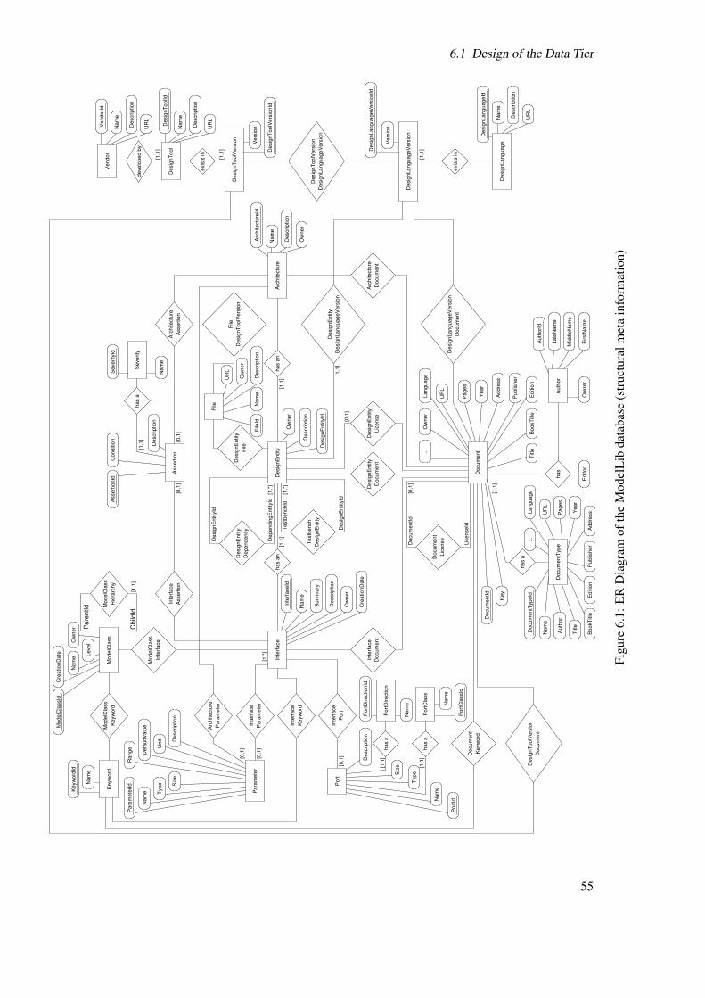
6.1 Design of the Data Tier
Child
Id
Pare
ntId
Assert
ion
Inte
rface
Inte
rface
ModelC
lass
Desig
nLanguageV
ers
ion
Vers
ion
Desig
nLanguageV
ers
ionId
exis
ts in
Keyw
ord
ModelC
lass
Keyw
ord
Nam
e
Keyw
ord
Id
has a
nhas a
n
develo
ped b
y
Desig
nLanguageV
ers
ion
Desig
nT
oolV
ers
ion
Para
mete
r
Inte
rface
Keyw
ord
Inte
rface
Port
Inte
rface
Assert
ion
Arc
hitectu
re
Para
mete
r
Arc
hitectu
re
Docum
ent
Desig
nT
oolV
ers
ion
Docum
ent
Desig
nLanguageV
ers
ion
has a
Editor
has
Docum
entT
ype
Auth
or
Language
Pages
Title
Nam
e
Docum
entT
ypeId
UR
L
Year
BookT
itle
Editio
nP
ublis
her
Addre
ss
...
Vendor
UR
L
Description
Nam
e
VendorI
d
Desig
nT
ool
Desig
nT
oolId
Description
Nam
e
UR
L
Docum
ent
Docum
entId
Key
Title
BookT
itle
Editio
n
Publis
her
Addre
ss
Year
Pages
UR
L
Language
Ow
ner
...
Para
mete
r
Nam
e
Para
mete
rId S
ize
Type
Unit D
escription
Defa
ultV
alu
e
Range
Port
Port
Direction
Nam
e
Port
DirectionId
has a
Description
Siz
e
Type
Nam
e
Port
Id
has a
Port
Cla
ss
Nam
e
Port
Cla
ssId
Description
Assert
ion
has a
Nam
e
Severity
Id
Severity
Conditio
nA
ssert
ionId
Desig
nT
oolV
ers
ion
File
Desig
nT
oolV
ers
ion
Vers
ion
Desig
nT
oolV
ers
ionId
File
Desig
nE
ntity
ModelC
lass
Hie
rarc
hy
ModelC
lass
Level
Nam
eO
wner
ModelC
lassId
Cre
ationD
ate
Inte
rface
Inte
rfaceId
Nam
e
Sum
mary
Description
Ow
ner
Cre
ationD
ate
Desig
nLanguageV
ers
ion
Desig
nE
ntity
File
UR
L
Ow
ner
File
IdN
am
eD
escription
Ow
ner
Desig
nE
ntity
Desig
nE
ntity
Id
Description
Arc
hitectu
reN
am
e
Description
Ow
ner
Arc
hitectu
reId
Auth
or
Ow
ner
FirstN
am
e
Mid
dle
Nam
e
LastN
am
e
Auth
orI
d
Keyw
ord
Docum
ent
Lic
ense
Docum
ent
Docum
ent
Inte
rface
Docum
ent
Desig
nE
ntity
Lic
ense
Desig
nE
ntity
Docum
ent
Arc
hitectu
re
exis
ts in
Desig
nLanguage
Description
Nam
e
Desig
nLanguageId
UR
L
Desig
nE
ntity
Testb
ench
Dependency
Desig
nE
ntity
Docum
entId
Lic
enseId
Testb
enchId
Desig
nE
ntity
Id
Dependin
gE
ntity
Id
Desig
nE
ntity
Id
[1,1
]
[1,*
][0
,1]
[0,1
]
[0,1
]
[1,1
]
[0,1
][0
,1]
[1,1
]
[1,1
]
[0,1
]
[1,1
]
[0,1
]
[1,1
]
[1,1
]
[1,1
]
[1,1
][1
,1]
[1,1
]
[1,*
]
[1,*
]
Figu
re6.
1:E
RD
iagr
amof
the
Mod
elL
ibda
taba
se(s
truc
tura
lmet
ain
form
atio
n)
55

6 Design
has a
has
Editor
Docum
entT
ype
Addre
ss
Month
Year
Chapte
r
Pages
Institu
tion
Org
aniz
ation
Publis
her
School
How
Publis
hed
Type
ISB
NIS
SN
EID
OID
UR
LU
RLD
ate
Note
Abstr
act
Annote
Language
Num
ber
Editio
nV
olu
me
Series
Journ
al
BookT
itle
Title
Auth
or
Nam
e
Docum
entT
ypeId
Ow
ner
Auth
or
Auth
orI
d
FirstN
am
e
Mid
dle
Nam
e
LastN
am
e
Inte
rface
Docum
ent
Inte
rface
Desig
nE
ntity
Docum
ent
Desig
nE
ntity
Lic
ense
Desig
nE
ntity
Arc
hitectu
re
Docum
ent
Arc
hitectu
re
Desig
nT
oolV
ers
ion
Docum
ent
Desig
nT
oolV
ers
ion
Desig
nLanguageV
ers
ion
Docum
ent
Desig
nLanguageV
ers
ion
Keyw
ord
Docum
ent
Keyw
ord
Keyw
ord
Id
Nam
e
Docum
ent
Docum
entId
Key
Num
ber
Title
BookT
itle
Journ
al
Series
Volu
me
Editio
n
Month
Year
Chapte
rP
ages
Institu
tion
Org
aniz
ation
Publis
her
School
Addre
ss
How
Publis
hed
Type
UR
L
ISB
N
ISS
N
EID
OID
UR
LD
ate
Note
Abstr
act
Annote
Language
Ow
ner
Lic
ense
Docum
ent
Lic
enseId
Docum
entId
[1,1
]
[0,1
]
Figu
re6.
2:E
RD
iagr
amof
the
Mod
elL
ibda
taba
se(d
ocum
entm
eta
info
rmat
ion)
56

6.1 Design of the Data Tier
Org
an
iza
tio
n
De
pa
rtm
en
t
Fu
nctio
n
Ad
dre
ss
City
Sta
te
ZIP
Co
de
Co
un
try
La
stN
am
eM
idd
leN
am
eF
irstN
am
eR
ole
Na
me
Use
rId
Birth
da
yP
ho
ne
Mo
bile
Fa
xE
−M
ail
UR
LIM
Se
rvic
e
IMN
ickN
am
e
No
te
Use
rDire
cto
ry
Jo
inin
gD
ate
Me
ssa
ge
Re
ply
To
Me
ssa
ge
Me
ssa
ge
IdR
ep
lyT
oId
Ow
ne
r
Da
te
Su
bje
ct
Co
nte
nt
Vis
ibili
ty
He
lpfu
lCo
un
t
To
talC
ou
nt
Ra
nkin
g
Re
ply
To
Id
Me
ssa
ge
Id
File
AC
L
Se
lectR
igh
t
Up
da
teR
igh
t
De
lete
Rig
ht
Ro
len
am
e
File
Id
File
AC
LId
File
acce
ss
allo
w/d
en
y
acce
ss
allo
w/d
en
y
De
sig
nE
ntity
Se
lectR
igh
t
Up
da
teR
igh
t
De
lete
Rig
ht
Ro
len
am
e
De
sig
nE
ntity
AC
L
De
sig
nE
ntity
Id
De
sig
nE
ntity
AC
LId
Me
ssa
ge
De
sig
nE
ntity
acce
ss
allo
w/d
en
y
Arc
hite
ctu
re
Se
lectR
igh
t
Up
da
teR
igh
t
De
lete
Rig
ht
Ro
len
am
e
Arc
hite
ctu
reA
CL
Arc
hite
ctu
reId
Arc
hite
ctu
reA
CL
Id
Inte
rfa
ce
AC
L
Se
lectR
igh
t
Up
da
teR
igh
t
De
lete
Rig
ht
Ro
len
am
e
Inte
rfa
ce
AC
LId
Inte
rfa
ce
Id
acce
ss
allo
w/d
en
y
Inte
rfa
ce
Mo
de
lCla
ssA
CL
Se
lectR
igh
t
Up
da
teR
igh
t
De
lete
Rig
ht
Ro
len
am
e
Mo
de
lCla
ssId
Mo
de
lCla
ssA
CL
Id
acce
ss
allo
w/d
en
y
Mo
de
lCla
ss
De
sig
nL
an
gu
ag
eV
ers
ion
Me
ssa
ge
De
sig
nL
an
gu
ag
eV
ers
ion
De
sig
nT
oo
lVe
rsio
n
Me
ssa
ge
De
sig
nT
oo
lVe
rsio
nD
esig
nT
oo
lVe
rsio
n
De
sig
nL
an
gu
ag
eV
ers
ion
Me
ssa
ge
De
sig
nL
an
gu
ag
eV
ers
ion
De
sig
nT
oo
lVe
rsio
n
Me
ssa
ge
Do
cu
me
nt
Do
cu
me
ntA
CL
Se
lectR
igh
t
Up
da
teR
igh
t
De
lete
Rig
ht
Ro
len
am
e
Do
cu
me
ntI
d
Do
cu
me
ntA
CL
Id
Do
cu
me
nt
acce
ss
allo
w/d
en
y
Me
ssa
ge
Use
r
[1,1
]
[1,1
][1
,1]
[1,1
][1
,1]
[1,1
][1
,1]
[0,1
]
Figu
re6.
3:E
RD
iagr
amof
the
Mod
elL
ibda
taba
se(u
serm
eta
info
rmat
ion)
57

6 Design
• DesignEntity – stores information on a possible/legal combination of an interface and anarchitecture. There may be several architectures associated to the same interface, so eachpossible interface/architecture combination makes a distinct design entity.
• DesignLanguage – stores information about the design or modelling language used todescribe a design entity. Examples of design languages are: SPICE, SystemC, VHDL-AMS).
• DesignLanguageVersion – stores information about the version of the design language usedto describe a design entity. The version may be, for example, a single number or a year.
• Vendor – stores information about the provider of a design tool.
• DesignTool – stores information about a tool that has been used to process the model.Examples of tools are simulators such as ADVance MS and Modelsim from Mentor Graphicsor SMASH from Dolphin Integration.
• DesignToolVersion – stores information about the version of the design tool used to process amodel.
• File – stores information about a file that contains a full model written in some designlanguage or part of it.
• Document – stores information about documentation associated to a model (e.g., applicationnote, user’s guide).
• DocumentType – stores information about types of documents, so that it defines whichattributes (e.g., year, chapter, ISBN, URL, etc.) a document (e.g., book, paper, manual, etc.)must contain.
• Author – stores information about the author of a document.
• UserDirectory – stores information about the user of ModelLib (e.g., name, affiliation, phonenumber, email address).
• Message – stores a comment, which is associated with a design entity, document, design toolversion, or design language version (e.g., how helpful a document is, or how a design entityworked).
• ModelClassACL – stores the rights a certain role is given to a certain model class.
• InterfaceACL – stores the rights a certain role is given to a certain interface.
• ArchitectureACL – stores the rights a certain role is given to a certain architecture.
• DesignEntityACL – stores the rights a certain role is given to a certain design entity.
• FileACL – stores the rights a certain role is given to a certain file.
• DocumentACL – stores the rights a certain role is given to a certain document.
This brief description should be enough to give an overview about the the entities and their meaningto the ModelLib library.
58

6.1 Design of the Data Tier
6.1.2 The Problem of Tuple-Wise Access Control
The library character of the ModelLib platform requires an uniform structure to store meta in-formation about AMS design models. The tuples in the tables of the ModelLib database containthese meta information. Thereby a table contains tuples with public information as well as highlysensitive information.
For example, a company has developed a secret new interface with ports and parameters. Theseinformation are stored in the ModelLib database and shall be only accessible to the members ofthe company. ModelLib also contains information about common interfaces and their ports andparameters, which are far from being a secret and thus accessible for everyone. Both, the secretand the public information are stored in the same table. Assuming the application controls whichinformation are presented to the user and which not, the problem is as follows. A user authenticateshimself to the application. Since the user accounts and the passwords are stored and managedby PostgreSQL, the application connects to the database server and forwards the users account,password, and the query for data. The database management system verifies the user and sends thequery results to the application, which is then verifying the user as no member of the company, andthus only showing the public information.
The application filters the data. The database management system is not aware of which tuple auser is allowed to see. It is only able to give rights to complete tables. If a user is valid and grantedto access a table, he will be able to see all tuples of this table.
This makes it possible that any user can read and change every information. He just has to findthe database server, what is not very difficult, and than use his own valid account and password toconnect to the database and to gain full access.
To deny access to the table is not a practical solution, because all users need access to the publicmodel information. Also, it is not a solution to create a different table for every user, because thiswould be impossible to manage once ModelLib reaches a certain number of users.
This explains why it is highly needed to find a way to protect every single tuple of every singletable and to prevent the bypassing of such a mechanism. Therefore the following possibilitiesexists:
• Excluding the account and password management from the database, so that a user is nolonger able to connect directly to the database.
• Shield the tuples inside the database to protect them.
It would not be efficient to reimplement the basic functionality of account management, whichcomes with PostgreSQL for free. Especially since a DBS would be the best solution to handlethe account data. Another argument against the first approach is, that the account managementin the database is much more capable to ensure data integrity. The strongest argument for theimplementation of the access control in the database is, that it can be kept even if the rest of theplatform is modified or completely replaced. That is why the development of a mechanism tocontrol the access tuple-wise inside the database is chosen. Additionally, this eases the developmentof connectors for extern tools, which cloud communicate directly with the database, while stillbeen put under access control.
The thesis of Frank Hertel [Her04] describes a similar problem. Two of the four solutions ex-plained there fit into the first possibility (excluding access control), which makes them inappropriatefor ModelLib. The other two are based on a feature of the commercial Oracle9i DBS used inMr. Hertel’s project. This feature allows to declare access privileges for single tuple of a table.
59

6 Design
database
(PostgreSQL)
Meta information
Data tier
HTTPS
access control
Tuple level
access control
Application level
tier
Business
Client
Presentation
tier
Figure 6.4: General concept of access control in ModelLib
PostgreSQL neither provides such a feature nor are the ModelLib project members able or willingto buy an Oracle9i DBS.
6.1.3 The General Solution for Tuple-Wise Access Control
As mentioned in the previous section, the general solution of the tuple-wise access control is amechanism inside the ModelLib meta information database. Figure 6.4 illustrates this concept. Thetwo levels are defined as follows:
Application level access control – is a set of mechanisms, implemented in the application,responsible to verify, which functions in the ModelLib platform is accessible by a certainuser.
Tuple level access control – is a set of mechanisms, implemented in the database, to verify,which tuple of a table is accessible by a certain user.
The question is, how to realise such a tuple-wise access control in a relational database?Before this question can be answered, it is necessary to introduce the concept of a view in a
relational database:
View – is a virtual (not materialised) relation containing values, which are persistently stored inone or more real relations. Views are defined through a query statement, which is executed inthe moment of its call. This means that the values in a view are composed on demand. Viewsare also described as named/stored queries, because the definition of a view is a query, whichis stored under the name of the view. [HS97]
To come to the solution, one could think of two tables/relations:
• The first relation is r. It contains the attributes ID as the primary key, A1, and A2. It symbolisesthe data, which shall be protected.
r = {id,a1,a2} with id ∈ ID,a1 ∈ A1,a2 ∈ A2
60

6.1 Design of the Data Tier
A2A1ID
23
1
2
3
4
29
23
41
13
13
17
31
James
James
James
Michael
Michael
1
3
2
4
true
true
false
false
true
USER REF G
2
James
James
1 true
true
USER REF G
2
A2A1
James
James
true
true
GID
1
2
29
23
13
13
USER
A2A1ID
1
2
29
23
13
13
acl
r
acl’
1.
2.
s
3.
t
Figure 6.5: Composition of the view
• The second relation is acl. It contains the attribute USER as the name of a user and REF asthe foreign key referring to r plus the attribute G as a boolean value representing whethera granted (true) or a denied (false) access. The attributes USER and REF are defined asprimary key for acl. This relation symbolises the access control list for the table r.
acl = {user,ref ,g} with user ∈ USER, ref ∈ REF, g ∈ G = {true, false}and ∀ ref ∈ REF(acl) ∃ id ∈ ID(r) : ref = id
If one selects all tuples from acl where the value of the attribute USER equals the current user andthe value of the attribute G equals true, he will receive the relation acl′, which contains all tupleswhere the current user has a granted right.
σUSER=’current user’ ∧ G=’true’(r) = acl′
The join of r and acl′, of course after the renaming the attribute REF to ID, produces the relation s.
r ./ (βID←REF(acl′)) = s with s = {id,a1,a2,user,g}
The projection of the attributes ID, A1, and A2 of the relation s produces a relation t, which containsall tuple from r that the current user is granted to see.
πID,A1,A2 = t with t = {id,a1,a2}
A view that is defined as the stepwise composed relation t returns only the tuple from r the user,who is currently querying the view, is granted to see. The following steps and the example inFigure 6.5 illustrate these composition of the view without the use of relational algebra:
1. Selection of all tuples form acl where the value of USER equals the current user (in theexample it is ‘James’) and the value of G equals true.
2. The join of the result with the table r.
3. The projection of the three columns ID, A1, and A2 from the result of the join.
The reason that this works is the concept of the view. Since definition of the view is a queryexecuted at the moment of its call, it will always return the tuple of the protected table the current
61

6 Design
user is granted to see due to the corresponding entries in the access control table. This is the firstpart of the problem solution.
The second part is the setting of global access rights to tables. The specification of SQL providesthe possibility to set privileges for accessing a complete table to every user independently. This isalso possible for a view. An administrator, responsible for the developed database, is the only one,who is allowed to access the tables (in the little example r and acl). He defines a view as above andafterwards grants access for all users to this view. As the result, a user is allowed to access the view,that is per definition showing only the tuples from the basic table, which the current user is grantedto see. The view is accessing the corresponding tables using the rights of the one who has definedthe view, the administrator. Whenever a user is trying to access a table directly, the DBMS willdeny the access.
To summarise, the general solution for a tuple-wise access control inside the database, that isfounded on the account management provided with DBS, is the concept of:
• One table containing sensible data,
• Another one containing the rights for tuples,
• A view joining the two tables,
• Granting rights for the view, but
• Denying rights for the tables,
It uses features that are part of SQL and therefore implemented in every relational database, whichis compatible to SQL. It remains the subject of the next section to explain, how the developedsolution is applied to the ModelLib meta information database. This is much more difficult thensimply joining two tables, because problems with recursive dependencies, a limited number ofjoins, the inheritance of rights, and the use of internal schema information occurred during therealisation.
6.1.4 The Special Solution for Tuple-Wise Access Control in ModelLib
Figure 6.3 shows that not every entity is related to an access control table. Only six entities (Mod-elClass, Interface, Architecture, DesignEntity, File, Document) have a direct table to control atuple-wise access. Most other entities depend on them or do not need a special access control. Atfirst it is described how such a table is structured and why.
Structure of a Table for the Access Control
The ER Diagram shows the structure of the tables containing access information. The term of anAccess Control List (ACL) is used, because they are based on the similar concept in modern filesystems (e.g., NTFS, XFS). They possess an attribute *ACLId (the ‘*’ is a place holder for theactual entity name) as a primary key. This is chosen due to uniformity reasons with other entities,though the combination of the *Id and the Rolename attribute would also be a valid primary key,because it is and must be unique.
The *Id attribute is a foreign key referring to the primary key of the corresponding entity. Thisensures data integrity, because it guarantees that the access control is actually referring to an existingtuple.
62

6.1 Design of the Data Tier
The Rolename column contains the role, for which a right to a tuple is specified. It might behelpful to describe the role concept as it is implemented in PostgreSQL 8.1. Where a
Role – can be a single user or a group of users. Roles can own objects of a database (e.g., tables,views) and assign rights to those object (not tuple) to other roles. Furthermore, it is possibleto inherit rights from one role to another by making the latter a member of the first. [Pos07]
For example, there are the roles James, Michael, and Vince representing real users. There is alsoa role Admin representing a superuser, who owns the objects. If the role Admin is granted to therole James, James would have all the rights Admin has. If than James is granted to Michael, hewould inherit the rights of James. Thereby, it is possible to specify whether Michael also inheritsindirectly the rights of Admin or only the rights of James. James can also be granted to Vince,because a role can be set to multiple other roles. The roles and their passwords are managed byPostgreSQL as well as the access to objects.
The other three columns of the *ACL contain the actual rights to execute functions, whichmanipulate the data of a table. This is similar to read/write access specified in an ACL for a filesystem. According to Section 3.2.1 these functions, respectively their rights, are:
• SelectRight – specifies whether a role is granted to see a tuple or not.
• UpdateRight – specifies whether a role is granted to change existing values of a tuple or not.
• DeleteRight – specifies whether a role is granted to remove a tuple or not.
If is not necessary to specify a right for the execution of the INSERT statement, because adding anew row does not harm any existing tuple.
A right is specified through the use of the boolean data type. The special case that SQL requiresa ‘unknown’ or null value for every data type is a lucky fact and very important, because it enablesa three state standard data type. A right can be either:
• true – for a grant,
• null – for an unspecified right, or
• false – for a deny.
Basically, an unspecified right means that a role is not able to execute the corresponding functionuntil the membership to another role (which has a grant on that function) allows it. In contrast, adenied right means, that the role and all of its members are never allowed to execute this function.Hence, a deny is more powerful then a grant, which is more powerful then an unspecified right:
null < true < f alse
The following example is used to illustrate the functionality of the *ACL tables a bit morecompressed. There are a table Document containing the documents with the ID 1 to 5 and the tableDocumentACL containing roles and rights as shown in Figure 6.6. Both, James and Michael aremember of a company and of the role of the same name. Both inherit the rights of Company, sothat the rights for every role results as follows:
• Company is allowed to select the tuples with the Id 1 and 2 from the Document table, but therole has no further rights. A tuple in Document, which has no corresponding entry for therole in DocumentALC is the same as all rights are null.
63

6 Design
DocumentACLId
12
3
4
5
6
DocumentACL
DocumentId
1
2
1
2
4
2
Rolename
Company
James
Michael
Company
James
James
SelectRight DeleteRight UpdateRight
true
true
true
true
true
false
null
null
null
true
true
true
false false
null
null
true
true
Figure 6.6: Example of the DocumentACL table
• James is allowed to select document 1, 2, and 4. He is also allowed to update values of thesedocuments and to delete the tuple with the Id 1 and 4. Though he is member of Company, itdoes not affect his permissions, because non of the rights of Company is stronger than his.
• Michael would have the right to select document 1 and 2 via his membership in Company,but he is denied for all rights regarding document 2.
The Three Basic Roles of ModelLib
The previous section introduced the role concept. Section 6.1.3 mentioned the possibility to setglobal rights to database objects and how this supports the protection of data. This concept isanother aspect, which is used in the ModelLib meta information database to guarantee the securityof data.
ModelLib knows three basic roles, which are the following:
mladmin – is a high level role with all possible rights, e.g., creating, dropping of all kind ofdatabase object, and full access to all tables, views, etc. A member of the mladmin role isalways operating on the real table, thus it is not necessary to specify any rights in any ACL.
mluser – is an authorised user, who has been verified positively. Members of this role are not ableto create or drop any database object. They have absolutely no rights on any table (except aselect right on some tables with non-sensitive data, e.g., DesignTools). What they have is thepermission to SELECT, UPDATE, DELETE, and INSERT on views, and only on views.
mlguest – is a role, which is declared for every unverified user of ModelLib. Like the mluser role,this role is not able to create or drop any database object and has absolutely no rights on anytable. This role has only the permission to SELECT on views. As the name is indicating it ismainly used for guests, so that they are allowed to see public information about models, butare unable to provide data.
The roles mlguest and mluser are conform to the actors in the Use Case Diagram in Figure 4.1.Every user must be member of a least one of these three roles otherwise he would not be able to
use ModelLib.
Data Manipulation in Views
The reader may have noticed, that this chapter often speaks of UPDATE, DELETE, and INSERToperations in the context of views. According to the definition of views, which declares them as not
64
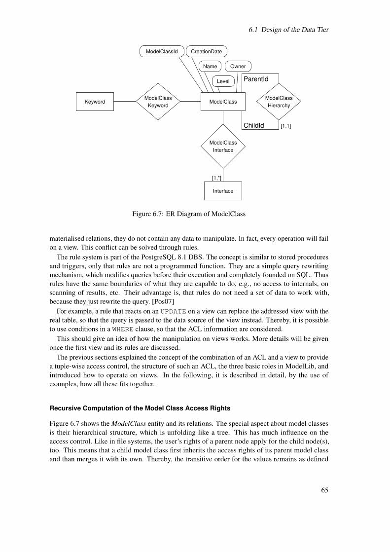
6.1 Design of the Data Tier
ChildId
ParentId
Interface
ModelClass
Keyword
ModelClassKeyword ModelClass
Hierarchy
ModelClass
Level
Name Owner
ModelClassId CreationDate
Interface
[1,*]
[1,1]
Figure 6.7: ER Diagram of ModelClass
materialised relations, they do not contain any data to manipulate. In fact, every operation will failon a view. This conflict can be solved through rules.
The rule system is part of the PostgreSQL 8.1 DBS. The concept is similar to stored proceduresand triggers, only that rules are not a programmed function. They are a simple query rewritingmechanism, which modifies queries before their execution and completely founded on SQL. Thusrules have the same boundaries of what they are capable to do, e.g., no access to internals, onscanning of results, etc. Their advantage is, that rules do not need a set of data to work with,because they just rewrite the query. [Pos07]
For example, a rule that reacts on an UPDATE on a view can replace the addressed view with thereal table, so that the query is passed to the data source of the view instead. Thereby, it is possibleto use conditions in a WHERE clause, so that the ACL information are considered.
This should give an idea of how the manipulation on views works. More details will be givenonce the first view and its rules are discussed.
The previous sections explained the concept of the combination of an ACL and a view to providea tuple-wise access control, the structure of such an ACL, the three basic roles in ModelLib, andintroduced how to operate on views. In the following, it is described in detail, by the use ofexamples, how all these fits together.
Recursive Computation of the Model Class Access Rights
Figure 6.7 shows the ModelClass entity and its relations. The special aspect about model classesis their hierarchical structure, which is unfolding like a tree. This has much influence on theaccess control. Like in file systems, the user’s rights of a parent node apply for the child node(s),too. This means that a child model class first inherits the access rights of its parent model classand than merges it with its own. Thereby, the transitive order for the values remains as defined
65

6 Design
above (null < true < false). A child class keeps its rights until a parent has a stronger value. Onany given node the access rights have to be computed recursively up to the root of the tree.
For example, five classes of models belong to a class special switches in the hierarchy electricaldomain, mixed-signal, switches, special switches. If someone wants to protect the five classes fromsomeone else, he simply denies all rights on the class special switches. In another scenario, a wholenew branch is added to a class, containing only public classes. Without any further specification ofrights this branch simply inherits all the rights from its parent under which it was added.
The problem with such a structure is that a view on the ModelClass table cannot just simply jointhe ModelClassACL table. It is necessary to look up if the current model class has a parent modelclass in the ModelClassHierarchy table and what are its rights and than does this one have a parentagain, and so on. Usually, the iteration depth is unknown or changing. A normal SQL query is notcapable to use a parameter or any dynamic value, which is required for a recursive computation ofthe effective access rights for a model class node. The SQL99 standard specifies the WITH clauseto have a recursive query, but unfortunately PostgreSQL 8.1 does not feature this clause [Pos07].Thus a recursive function had to be written.
Figure 6.8 and 6.9 show the Activity Diagrams of two functions developed to compute theeffective access control rights for every model class. The first one is executed in the moment of aquery for the ModelClassEffectiveACLView. It sets initial parameters, which is necessary, becausethe view itself can not provide a row of the ModelClassACL table. Thus the view is not able to callthe recursive function directly. After setting the parameters, the function loops through a set of Idsfrom all model classes. Thereby it calls for every element of the set the second function, which isgoing up the hierarchy, computing the rights from the root, and then returning them.
The second function does the actual work. It receives a row in form of an ACL tuple as input.First it checks if all rights are already denied, which means that the values will not change, nomatter what is specified in any parent node. Thus it will lead to the termination of the algorithmwith the return of the row. If no entry in the ModelClassACL table for the current role and modelclass exists, the algorithm detects the parent model class, calls itself with the parent model classId, and overwrites the result with the original Id. If no parent node is detectable, the algorithmterminates by returning a row of an ACL tuple. In case of a positive check for an existing entryin ModelClassACL, the algorithm checks for a denied SelectRight in the current variables, thanfor one in the ACL, than for a granted right in the ACL. Than, this is processed analogously forUpdateRight and DeleteRight, which is addressed by the fact, that Figure 6.9 shows a grey dottedbox around some activities to compute the SelectRight. The same gray dotted line can be seen inthe activities check update rights and check delete rights. This shall symbolise that the algorithm tocompute the update and delete rights, is exactly the same as for the select rights, only that everySelect must be replaced by Update and Delete. This is not strictly UML conform, but simplifies thefigure.
Once the two functions have terminated and ModelClassEffectiveACLView contains the effectiverights for the current user and for all model classes, it is possible to join the ModelClass table withthis view (like the normal solution without a tree like structure is intended). The result is a relationthat contains only the tuple the user is granted to access. Additionally, the ModelClass table hasan attribute Owner, which contains the role name of the owner of the model class. It ensures thatthe owner of a model class is always able to access his class. It is intended to present own modelclasses in a separate category ‘own model classes’, so that it is not effected from the hierarchy andany specified ACL entries. It also prevents model classes from ‘getting lost’ in the case that they
66

6.1 Design of the Data Tier
get all ModelClassIDs
from ModelClass
loop
current user
set Rolename =
set ModelClassId =
current Id
set SelectRight = null
set UpdateRight =null
set DeleteRight =null
call modelclassacl_recursive
_compute_function(row)
return
ClassACL
row
of Model
of all Model
ClassIDs
list
list
ModelClass
ACL
of effective
called
modelclassacl_compute_function()
write result
in list
end of list
Figure 6.8: Activity Diagram of the function called by the ModelClassEffectiveACLView
67

6 Design
ClassACL
row
of Model
entry in ModelClassACL
ClassID and Rolename an
check if for this Model
yes
no
check if current
SelectRight =false
no
yes
check if SelectRight
in acl =false
no
yes
check if SelectRight
in acl =true
yes
no
set SelectRight =true
set SelectRight =false
UpdateRight
check
check
DeleteRight
check if for this Model
ClassID a ParentID entry
in ModelClassHierarchy
yes
no
ModelClassID
memorise current
get ParentID
call modelclassacl_
recursive_compute_
fun. with ParentID
return set with
memorized ID
replace ID of the
row
ModelClass
ACL
of effective
SelectRight
check
no
yes
check if all current
rights =false
return
modelclassacl_recursive_compute_function()
called
Figure 6.9: Activity Diagram of the recursive function to compute the effective rights
68

6.1 Design of the Data Tier
are not correctly linked into the hierarchy. The following algebra term defines the ModelClassViewin its final version:
ModelClassView = πModelClassId, Name, Level, CreationDate, Owner(s ∪ r) with
s = σ(ModelClass) ./ σSelectRight=’true’(ModelClassEffectiveACLView)r = σOwner=’current user’(ModelClass)
As mentioned above, rules have to be defined to allow data manipulation on the view, such asUPDATE and DELETE, and INSERT. These rules replace the query statement on the view accordingto their definition. They use the condition to verify if the operation is allowed for a certain tuple ornot. Assuming a tuple t of the relation ModelClassView shall be updated. The corresponding rule isdefined to do this update on the ModelClass table instead, but only if the ModelClassId to update isan element of the set of ModelClassIds in the ModelClassEffectiveACLView, which the current userhas a granted update right. The equivalent algebra expression is the following:
UPDATE (t(ModelClassView)) =
{UPDATE (t(ModelClass)) ∀ t ∈ r∅ else
with
r = (q ∪ s)q = πModelClassId
(σRoleName=’current user’ ∧ UpdateRight=’true’(ModelClassEffectiveACLView)
)s = πModelClassId (σOwner=’current user’(ModelClass))
The rule for a delete statement is analogously defined with a DELETE instead of the UPDATE. Therule for an insert statement is simply changing the addressed relation, because everyone is grantedto add new tuples.
INSERT ((t(ModelClassView)) = INSERT (t(ModelClass))
The corresponding SQL statements of the ModelClassView and its rules are shown in Section 7.1as part of the chapter about the implementation.
This section described how a particular ACL is structured and handled, and how rules are used tomanipulate data in a view. The next section is setting the scope a bit wider by showing how entitieswithout an own ACL can be controlled by the ACL of an entity they are linked to.
Access Control of Entities without an own ACL
Looking at Figure 6.3, one may wonder why only six entities have an ACL table and the rest not.This does not mean that the data they are containing is public. Most of the data therein needs to besecured as the one in the tables with an own ACL.
Most of the entities have a strong relationship to the entities with an own ACL, so that they areindirectly depending on this ACL. The topic of this section is to describe how the security forsuch linked entities is realised. The ER Diagram in Figure 6.10 shows a typical example of anentity (Interface) with an ACL and entities (Port, Parameter), which are linked to that superiorentity and therefor need to be under the scope its ACL. Similar to entities with an own ACL, theaccess control of a linked entity is based on the ACL-view-rule concept, except that linked entitiesuse the rights of the entity they are linked to. Therefore the join includes not only the data table
69

6 Design
Interface
InterfaceId
Name
Summary
Description
Owner
CreationDate
Port
InterfacePort
PortDirection
Name
PortDirectionId
has a
Description
Size
Type
Name
PortId
has a PortClass
Name
PortClassId
InterfaceACL
SelectRight
UpdateRight
DeleteRight
Rolename
InterfaceACLId
InterfaceId
access
allow/deny
Parameter
InterfaceParameter
Unit
Size
Type
Name
Description
DefaultValue
ParameterId
Range
[0,1]
[1,1]
[1,1]
[1,1]
[0,1]
Figure 6.10: Example of linked entities without an own ACL
itself and the ACL table, but also the relationship table and the linked table. This makes the rulesmore complex, but not less efficient.
For instance, every tuple of the table Parameter is linked to either one Interface tuple orone Architecture tuple (the cardinality is specified for a particular relationship, so that from theinterface-parameter-perspective parameter tuples exist, which are not linked to an interface). Thus aParameter tuple is only selectable if the current user has a select right on the corresponding Inferfacetuple. This includes the InterfaceParameter table, which contains the attribution of parameters toan interface via their Ids. In the following it is explained how the view of the parameter table andits rules are composed:
ParameterView (pv) – Since the InterfaceView (iv) already contains only interface tuples thecurrent user is allowed to see, the InterfaceView can be used to be joined with the InterfacePa-rameter (ip) table and than with the Parameter (p) table. This is expressed by the followingalgebra term:
pv = p ./(πInterfaceId(iv) ./ ip)
)Update Rule – An update on a tuple of the ParameterView (pv) is not directly granted by a right
in an ACL table. A user has indirect rights to change tuples of an interface view. Parameterdata, which belong to an interface are also part of the information about this interface. Ifsomeone changes the values of a parameter tuple, it also effects the interface. Thus, anychange on parameter information updates an interface. This is why a user should only be ableto manipulate (update, delete, or insert) a parameter tuple if that particular user is grantedan update right in the InterfaceACL (ia) of the corresponding interface. Otherwise a change
70

6.1 Design of the Data Tier
of the parameter information could have a destructive effect on the stored definition of themodel interface. The algebra expression for the update rule is the following:
UPDATE (t(pv)) =
{UPDATE (t(p)) ∀ t ∈ r∅ else
with
r = (p ./ pi ./ (q ∪ s))s = πInterfaceId (σOwner=’current user’(Interface))q = πInter f aceId
(σUpdateRight=’true’ (rm ./ ia)
)−πInterfaceId
(σUpdateRight=’false’ (rm ./ ia)
)rm = πRolename (βRolename←MemberIn (πMemberIn (σRolename=’current user’(rmv))))
The relation rmv is an abbreviation for the term RolesMembershipView. It depicts a viewwhich uses internal schema information of the DBMS to determine of which role the currentuser (who is a role by himself) is a member. Though it is necessarily used here, it is describein detail in the next section. The previously mentioned ModelClassEffectiveACLView containsonly access rights for the current user, because it is computed by a function, which returnsonly values for the current user. In all other cases of the security system of ModelLib, therights are determined directly from the ACL tables. Thus, more then one entry (dependingon how many other roles a user is member of) are determining a specific right for a user.According to the concept of roles (see Section 6.1.4), a user can be member of various otherroles, so that a right is granted for one role, but denied for another role. In such a case, theuser has no permission to access the particular tuple. This is the reason why first the setof InterfaceIds with granted rights is retrieved and then the set of InterfaceIds with deniedrights is subtracted (difference operator) from that set. The result set q is united with the setof InterfaceIds the current user owns, and than joined with the ParameterInterface relationand the Parameter relation. The result is a relation of tuples linked to an interface, which thecurrent user is permitted to update.
Insert Rule – For an insert of a tuple in the ParameterView apply the same conditions as for anupdate. A tuple can only be inserted and linked to an interface, if the user is granted theaccording update right. The algebra expression is analogously defined to the one for anupdate, thus not presented here.
Delete Rule – A delete of a tuple in the ParameterView is also only possible, if the deleting user isgranted to update the corresponding interface tuple.
This concept of access control is applied to every view of the linked entities. Linked entities areall entities, which have no own ACL, but have a strong semantical relationship to an entity withan ACL. A user is only permitted to manipulate these entities if, he is permitted to update thecorresponding entity. The Port entity is one of these linked entities, but is showing an additionalcharacteristic. It shows a relationship to the entities PortDirection and PortClass. Both entitiesbelong to a small group of entities, which cannot be modified by a guest or an authorised user. Theyare used to specify a closed set of data for an entity attribute. For example, a port must specify adirection, which can be one of input, output, input/output, or none. These values hold true for everyport. This group of global entities include:
• DesignLanguage,
71

6 Design
• DesignLanguageVersion,
• DesignTool,
• DesignToolVersion,
• DocumentType,
• PortDirection,
• PortClass,
• Severtiy, and
• Vendor.
They are managed by the content manager (see Figure 4.1). Since they are not bound to a singletuple and also not changeable by the user, they do not need a view or a special ACL. The rights areset global, which means that the basic roles mluser and mlguest have only a select right on thesetables, while members of the mladmin role have full rights on them.
This section described how entities with an ACL and such without interacted through theirrelationships to ensure an effective access control mechanism.
Internal Schema information for Roles Membership
The previous section mentioned the so called RolesMembershipView (rmv), which provides infor-mation about the membership the users or roles have in other roles. Therefore it is necessary toaccess meta information of a database, which contain data about:
• which roles in the database exists, and
• which role is member of which role.
The PostgreSQL stores all kind of information about a database in tables of an internal schema,which is accessible by the owner of the database. This so called information_schema contains,amongst others, the tables enabled_roles (er) and applicable_roles (ar). Querying the first returnsall roles of the database, while the second provides role names and the names of roles they are amember of. After duplicating the enabled_roles (er) table by joining it with itself, it is possible tounite this duplicated relation with the projection of the first two columns of the applicable_roles (ar)table. The result is the RolesMembershipView (rmv). The definition in algebra form is as follows:
rmv = (r ∪ s) with
r = πrolename,memberin (er ./ (βmemberin←rolename(er)))s = πgrantee,rolename (ar)
The advantage of the union operation for r and s instead of a join is that the view gets tuples, whichexpress that a role is member of itself. This is very helpful, because a query for the membership ofa role returns a single column instead of all membership roles in one set and the origin role in aseparate one. This makes it much handier to use such query for access control checks, because thissingle column can be compared to the RoleName column in an ACL table.
Though this view is very simple, it is very important. The RolesMembershipView is the mostused view in the security mechanism, it is part of almost every query addressing a ACL table. TheSQL implementation of this view can be found in Section 7.2. It also gives an idea of how theinternal schema can be used.
72

6.1 Design of the Data Tier
Handling the Complexity of ACLs
Thinking of the number of tuples and users, which will grow over time, the access control maybecome very complex. Hence, a mechanism is required, which allows as much control as needed,but as less specification effort for rights as possible. A first step is the role system provided byPostgreSQL to group users, so that rights can be specified for various users at once. A second stepis kind of inheritance of rights from one entity to another. This ease of handling the ACL tables isthe topic of this section.
The inheritance of rights affects those entities with an own ACL, which also have a kind of a‘part of’-relationship. This includes the following tables:
• DesignEntity – which is always an implementation of a certain architecture,
• Architecture – which is always the internal description of an interface,
• Interface – which is always part of at least one model class, and
• ModelClass.
Thereby, the idea is to inherit the specified ACL rights of the belonging entity, as long as no rightsfor the inheriting entity are specified. For instance, in case of no specified access rights for aDesignEntity tuple, the rights from the corresponding architecture have to be applied to control theaccess. Are these rights also not specified, the rights from the corresponding interface have to beapplied, otherwise the tuple can not be accessed. Figure 6.11 illustrates this concept.
The relationship between ModelClass and Interface does not fit to this concept, though the rightsof Interface are related to the one of ModelClass. It is different from the relationship betweenInterface, Architecture, and DesignEntity, because an interface can only be seen if it is element ofa model class the user is allowed to see. That means whenever the ModelClassView contains thecorresponding model class. For all other operations (delete, insert, update) the InterfaceACL isused to determine the rights.
This kind of inheritance of rights makes it possible that a new interface can simply be sortedinto a public model class and become available for many users. This model is then selectable,without any further rights specification. At a later time, the owner of this interface is free to decideto grant additional rights. These rights will apply to the architecture and the design entity. At onepoint the owner decides to deny, for example, the update right to some of the architectures for hisinterface. At the moment one entry (in the ArchitectureACL) for a certain architecture is made, thisarchitecture does not inherit rights any longer. Only the now specified rights in the ArchitectureACLapply to this architecture. Thus it is not possible to ‘forget’ a role.
The Activities Diagram in Figure 6.11 would be easy to implement in a complete function like inthe case of the recursive computation of the effective rights for the model classes (see Section 6.1.4).It was decided not to do this, because the use of such an extra function would cost flexibility andplatform independence. Another approach, which used the view concept to compose the effectiverights, caused a major loss in performance. The approach made it necessary to join more then 10views, while each of them would be queried on demand. This led to a dead-end solution, becausethe composition, for example, for the effective architecture rights took more than 6 minutes, even ifthe ACLs had less then 25 tuples each. A much more efficient but similar approach was developed.It uses triggers and one additional table, each containing the effective rights fort the inheritingrelations (Architecture, DesignEntity).
73

6 Design
access a tuple
of
determine right for a
certain DesignEntity
specified
not specified determine right for a
certain Architecture
specified
not specified determine right for a
certain Interface
specified
not specified check if Interface is in
a selectable ModelClass
only
show tupleapply rights
DesignEntity Interface
Architecture
no
yes
Figure 6.11: Activity Diagram of the rights inheritance
74
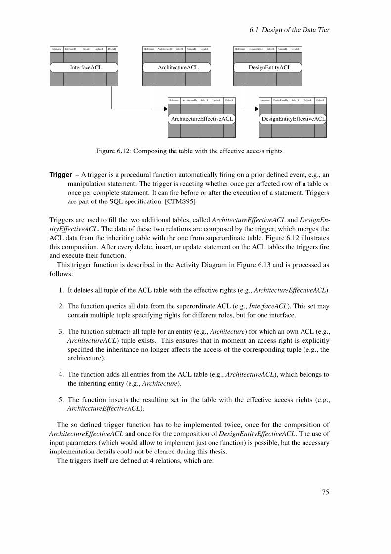
6.1 Design of the Data Tier
SelectR UpdateR DeleteRRolename InterfaceID SelectR UpdateR DeleteRRolename ArchitectureID SelectR UpdateR DeleteRRolename DesignEntityID
SelectR UpdateR DeleteRRolename DesignEnityIDSelectR UpdateR DeleteRRolename ArchitectureID
InterfaceACL ArchitectureACL DesignEntityACL
ArchitectureEffectiveACL DesignEntityEffectiveACL
Figure 6.12: Composing the table with the effective access rights
Trigger – A trigger is a procedural function automatically firing on a prior defined event, e.g., anmanipulation statement. The trigger is reacting whether once per affected row of a table oronce per complete statement. It can fire before or after the execution of a statement. Triggersare part of the SQL specification. [CFMS95]
Triggers are used to fill the two additional tables, called ArchitectureEffectiveACL and DesignEn-tityEffectiveACL. The data of these two relations are composed by the trigger, which merges theACL data from the inheriting table with the one from superordinate table. Figure 6.12 illustratesthis composition. After every delete, insert, or update statement on the ACL tables the triggers fireand execute their function.
This trigger function is described in the Activity Diagram in Figure 6.13 and is processed asfollows:
1. It deletes all tuple of the ACL table with the effective rights (e.g., ArchitectureEffectiveACL).
2. The function queries all data from the superordinate ACL (e.g., InterfaceACL). This set maycontain multiple tuple specifying rights for different roles, but for one interface.
3. The function subtracts all tuple for an entity (e.g., Architecture) for which an own ACL (e.g.,ArchitectureACL) tuple exists. This ensures that in moment an access right is explicitlyspecified the inheritance no longer affects the access of the corresponding tuple (e.g., thearchitecture).
4. The function adds all entries from the ACL table (e.g., ArchitectureACL), which belongs tothe inheriting entity (e.g., Architecture).
5. The function inserts the resulting set in the table with the effective access rights (e.g.,ArchitectureEffectiveACL).
The so defined trigger function has to be implemented twice, once for the composition ofArchitectureEffectiveACL and once for the composition of DesignEntityEffectiveACL. The use ofinput parameters (which would allow to implement just one function) is possible, but the necessaryimplementation details could not be cleared during this thesis.
The triggers itself are defined at 4 relations, which are:
75

6 Design
trigger fired
delete all ACL tuple of the EffectiveACL of S
for each tuple of C receive all SACL tuple
of the corresponding S
subtract all tuple from this set which
have an own entry in the CACL
add all tuple of CACL
write this set in the EffectiveACL of C
C = current entity
S = superordinate entity
Figure 6.13: Activity Diagram of the trigger function
• InterfaceACL – so that a change on this table causes a recomposition of the ArchitectureEf-fectiveACL,
• ArchitectureACL – so that a change on this table causes a recomposition of the Architecture-EffectiveACL,
• ArchitectureEffectiveACL – so that a change on this table causes a recomposition of theDesignEntityEffectiveACL, and
• DesignEntityACL – so that a change on this table causes a recomposition of the DesignEnti-tyEffectiveACL.
This combination of effective rights tables and triggers enables the inheritance of rights asrequired and, at the same time ensures the integrity of the access control data. The inheritance ofrights eases the management, because rights must not be specified on every entity, even though thisis possible. It is expected that in most cases it will be enough to specify rights for an interface anduse the same rights for architectures and design entities.
6.2 Design of the Business Tier
To speak as an architect, a solid house needs a solid foundation. The presentation tier and thebusiness tier are this house, build on the data tier. In the case of ModelLib, the design of thedata tier needed to be done well thought, especially in meeting the requirements regarding theprotection of IP. The development of the tuple-wise access control and its realisation contributedthe major part to this thesis. The realisation of other requirements, e.g., the browsing for models,the review process for new models, or the connection interface to EDA tools have a lower priority
76

6.2 Design of the Business Tier
than the security aspects. Additionally, new requirements for the information stored in the databaseand their protection emerged during the realisation of the data tier. The resulting problems fromthe experiences with the ModelLib prototype and the discussions with the project partners had tobe solved before the design of the other tiers makes sense. Of course, the realisation of securitymechanisms in the data tier leads to less effort for these issues in the business tier. A business logicis now able to simply pass queries and let the ACL mechanics do the work of verification. However,the limited amount of time for this thesis left did not allow a detailed design of the business and thepresentation tier. That is why only a first tentative draft is presented.
The technology chosen for the realisation of the business tier are EJB (see Section 5.2.2),in fact Entity Beans and Session Beans. The use of Entity Beans mostly benefits from the apersistence manager, which is responsible for the consistence and persistence of data. It managesconcurrent access to shared objects. Thus Entity Beans can represent the database objects. Thepersistence manager has to be mapped to the objects in the database. This so called object-relationalmapping [KS06, pp. 5] is not trivial, especially in combination with views. However, once thepersistence manager is established, it prevents the developer from the use of SQL statements to keepthe data, handled in the application, synchronous with those in the underlying data source. [KS06]The persistence manager also eases the maintenance of the system, because changes in the databasemust not be adapted to the SQL statements in the application. As already mentioned, the datatier absorbed the most work, thus the object-relational mapping for the persistence manager is notapplied here.
An approach for design of the business tier without a persistence manager has two possiblesolutions to use Entity Beans:
• Database objects are handled by SQL statements through methods within the Entity Beans,
• Database objects are handled by SQL statements through separate Session Beans.
The author of this thesis favours the second approach, because the Session Beans can be easilyremoved in case that a persistence manager is established. The Class Diagram in Figure 6.14 showsthe idea of the design for the business tier. The database objects are represented by Entity Beanclasses. Their parameter would be mainly the attributes of the table or, in case of a composition oran aggregation (e.g., Document and Author) other entities. Their methods are the setter and gettermethods for the parameters (not specified in the Class Diagram due to clearness reasons). TheEntity Beans classes are associated with their respective handler Session Beans, which instantiatethe Entity Beans. Handler Beans inherit the methods of the abstract class EntityBeanHandler andmay implement additional parameter and methods. The EntityBeanHandler is abstract (with emptymethods), because each inheriting handler Bean must implement the methods differently dependingon SQL statements. These statements implement the interaction with the database to query thevalues for the entities. The EntityBeanHandlerRemote interface is the connection point for othercomponents of the system. The GlobalSessionBean is stateful and instantiates a session. Thissession is bound to the client and carries the user information and a database connection. Thedatabase connection is kept during an active session, which makes it reusable for the involvedEntityHandler Beans. The interface GlobalSessionRemote makes the Bean available for othercomponents, e.g., Servlets or JSP.
77
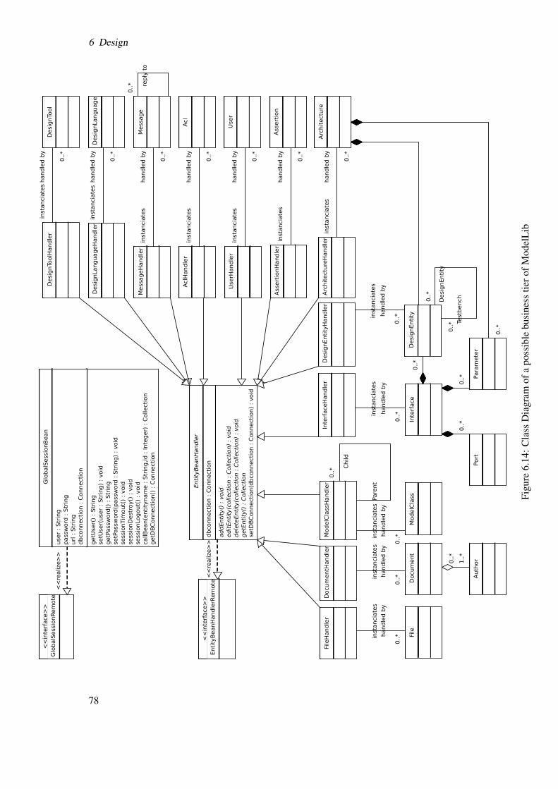
6 Design
Figu
re6.
14:C
lass
Dia
gram
ofa
poss
ible
busi
ness
tiero
fMod
elL
ib
78

6.3 Design of the Presentation Tier
Figure 6.15: Possible elements of the presentation tier of ModelLib
Login/User Info
Header
Footer
Main Menu
ContentModel Class
Navigator
Figure 6.16: Possible layout for the main ModelLib Web page
6.3 Design of the Presentation Tier
The presentation tier should also be designed modularly. For example, one main page includesother pages. Information, which is used more than one time should be separated in an own page,so that it is reusable in multiple situations. Figure 6.15 gives an idea of possible componentsof the presentation tier. A main page, e.g., index.jsp includes components such as header.jsp,footer.jsp, and menu.jsp. They all provide elements of the presentation, which are part in everypage. The content.jsp represents an element with different content depending on the selected menuoption, e.g., a page for managing of data about the user or a page for the design tool information.
A typical layout of a page is presented in Figure 6.16. The header contains information aboutnavigation, e.g., which element the user selected or what his last action was. The login section iswhere the user enters his account and password for the authentication. If he is already authenticated,information about his account are presented instead, e.g., membership of roles, last model browsed,etc. The footer shows external links and information about the ModelLib system, e.g., applicationversion, responsible developer, etc. The model class navigation part enables a user to browsethe classes in their hierarchy, like in file browsers (e.g., Microsoft’s Windows Explorer, KDE’sKonqueror). The main menu section provides access to certain presentation parts of ModelLib, e.g.,design tools, references, help section, etc. The content section presents the information the user hasrequested.
79

6 Design
Figure 6.17: Presentation of the meta information about design tools [MV06]
Since the business tier and the presentation tier have not been implemented yet, some screenshotsof the prototype are used to give an idea how the meta information from the database can bepresented.
Figure 6.17 shows the header information on top, giving the user the information that he isactually in the Design Tools section. Below this, one can see the main menu to enter the differentsections of ModelLib. What follows is the name of the design tool and its vendor (ADVance MSfrom Mentor Graphics Corp.). Also a table of design languages and their versions supported bythe design tool and references to documents can be seen. The bottom of the screenshot shows thefooter, which contains user information and additional links.
Footer, main menu, and header are also included in the second screenshot (Figure 6.18). It showsmeta information about a model, in this case an active low pass filter. The model class path is ontop followed by the interface meta data. Two tables present the parameters and the ports, whichbelong to this interface. The corresponding architecture information comes after the interfacesection. Following the description of the architecture, the information about the design entitiesimplementing this architecture in particular design languages. A table of attached files and thereferences for the model follow the design entities. The name of a file is the link to the modelsource code in the Subversion repository, so that the code can easily be found. One can see thatseveral add and edit buttons (e.g., Add Architecture, Interface Edit) are displayed throughout thepage. The implementation of a new version, based on this thesis, should only make such buttonsavailable, if the user possesses the required rights to delete, update, or insert information.
These two examples, though they are borrowed from the prototype, are very suitable to give anidea of how meta information about AMS design models can be presented to the user.
80

6.3 Design of the Presentation Tier
Figure 6.18: Presentation of the meta information about a model [MV06]
81

6 Design
This chapter described the design of the Web-based application regarding the chosen N-tierarchitecture. The focus was clearly on the data tier. This is why the relation to the two other tiersis unrepresented. The reason is the high relevance of the protection of some information in thedatabase regarding the IP.
82

7 Implementation
According to the software life cycle the implementation follows the design. The previous chapterexplained the design of the ModelLib application, especially the data tier. The high priority ofsecurity aspects caused the focus of this work on the design and implementation of the data tier.That is why only a tentative draft for the other tiers could be developed. Without a design, there isno implementation. Thus, the topic of this chapter is the implementation of the data tier.
From the 57 tables, 27 sequences, 2 functions, 2 trigger functions, 4 triggers, and the 46 viewswith 129 rules, implemented in the database, only a few aspects are described in this chapter. Theyare related to the presented issues of the design of the data tier. Further it is not intended to providethe complete source code or describe every function or unit test. Moreover, examples are used toillustrate the realisation and the test concepts.
7.1 Computation of the Model Class Access Rights(Implementation)
Section 6.1.4 described two functions necessary to compute the effective rights of model classesdepending on their parent class. The PL/pgSQL – SQL Procedural Language, provided withPostgreSQL, is used to write such a recursive function. Though the use of such an additionallanguage decreases the portability and platform independence, in this case it could not be avoided.PL/pgSQL has a manageable set of keywords, which allow loops, if-then conditions, etc. to addcontrol structures to the SQL language. It is easy to read and to learn.
The Listing 7.1 shows the source code of the function for the ModelClassEffectiveACLView fromthe Activity Diagram (Figure 6.8) as an example of PL/pgSQL. Line 1 and 2 specify the name andinput parameter of the function. The lines 5 to 7 declare the variables of the function. Line 13 fillsthe variable with the ModelClass tuples via a SELECT statement and loops through them. Lines15 to 19 set the initial values for the parameter, which are handed over to the recursive function.Line 20 fills the return variable with the result from the recursive function (which is much morecomplex, and thus attached in the Appendix A.1). The Lines 29 and 30 set global security rightsfor this function.
Listing 7.1: Source code of modelclassacl_compute_function()
1 CREATE OR REPLACE FUNCTION modelclassacl_compute_function()2 RETURNS SETOF modelclassacl AS3 $BODY$--This function initialises the values and hands them to the ↵
recursive function as parameter. A view or a query are not able to↵
call a function with such a parameter4 -- and can not set the rolename in this parameter. The rolename would ↵
otherwise been overwritten in the recursive function5 Declare6 var_modelclassacl_row modelclassacl%Rowtype;--type ’Rowtype’ is one or↵
more rows of the table named before ’%’ and its column types
83

7 Implementation
7 var_modelclass_row modelclass%RowType;8
9 Begin10 --var_modelclassacl_row will be filled with an acl row for every ↵
modelclass11 --merged from all rows of modelclassacl which contain roles the ↵
current user is member of12 --and the rights of parent nodes of the modelclass13 for var_modelclass_row in Select modelclassid FROM modelclass ↵
Loop--for all modelclasses14
15 var_modelclassacl_row.rolename := current_user;--initialises with the ↵
current user and guarantees that this is the one checked for in ↵
recursion16 var_modelclassacl_row.modelclassid := ↵
var_modelclass_row.modelclassid;--initialises with the ↵
modelclassid from the loop17 var_modelclassacl_row.selectright:= null;--initialises with the ↵
weakest right18 var_modelclassacl_row.updateright := null;19 var_modelclassacl_row.deleteright := null;20 Select Into var_modelclassacl_row * From ↵
modelclassacl_recursive_compute_function(var_modelclassacl_row); ↵
--call recursive function with the initialised variable21
22 return next var_modelclassacl_row;23 End Loop;24 return;25 End;26 $BODY$27 LANGUAGE ’plpgsql’ VOLATILE;28 ALTER FUNCTION modelclassacl_compute_function() OWNER TO mladmin;29 GRANT EXECUTE ON FUNCTION modelclassacl_compute_function() TO mladmin;30 GRANT EXECUTE ON FUNCTION modelclassacl_compute_function() TO public;
This function is called from the ModelClassEffectiveACLView. The view is defined in SQL asshown in Listing 7.2
Listing 7.2: SQL statement for the ModelClassEffectiveACLView
1 CREATE OR REPLACE VIEW modelclasseffectiveaclview AS2 SELECT modelclassacl_compute_function.rolename,3 modelclassacl_compute_function.modelclassid,4 modelclassacl_compute_function.selectright,5 modelclassacl_compute_function.updateright,6 modelclassacl_compute_function.deleteright7 FROM modelclassacl_compute_function() ↵
modelclassacl_compute_function(rolename, modelclassid, ↵
selectright, updateright, deleteright, modelclassaclid)8 ORDER BY modelclassacl_compute_function.modelclassid;9 ALTER TABLE modelclasseffectiveaclview OWNER TO mladmin;
10 GRANT ALL ON TABLE modelclasseffectiveaclview TO mladmin;11 GRANT SELECT ON TABLE modelclasseffectiveaclview TO mluser;
84

7.1 Computation of the Model Class Access Rights (Implementation)
1211 13 21 22 23 31 32 33
1 2 3
Figure 7.1: An example of a model class hierarchy
Table 7.1: Possible ACL values and their theoretic result in a computation (n=null,1=true,0=false)ModelClassId
ParentID 1 2 3Parent right value n 1 0ChildID 11 12 13 21 22 23 31 32 33Child right value n 1 0 n 1 0 n 1 0Child right value inModelClassEffectiveACLView n 1 0 1 1 0 0 0 0
This view contains the rights the current user has for every model class. Due to the fact that onlythree values occur in each right column of an ACL, the result of the recursive function is relativelyeasy to foretell. Basically nine possible cases exists, three values in a parent node and three foreach in the child nodes. All other cases, no matter if higher or lower in the model class hierarchy,are one of these nine cases. Additionally, the computation of rights for select, updates, and deletehave all the set of possible values (null, true, false), so that one right is representative for all.
The hierarchy shown in Figure 7.1, has three root nodes each having three child nodes. All casescan be simulated with this hierarchy. A specification of access rights as described in Table 7.1should result in effective rights as to read in the last row of this table. This specification of rightswas used to test the ModelClassEffectiveACLView and thereby the underlying functions. The modelclass hierarchy was build as shown, the values had been inserted in the ModelClassAcl table,and than the ModelClassEffectiveACLView was selected. The view presented the same values asexpected. Thus it is reasonable to say that the functions are working correctly.
The view ModelClassview joins the ModelClassEffectiveACLView with the ModelClass table.The view for model classes is defined in SQL as shown in Listing 7.3. Therein the lines 4 to 8define the conditions, under which a tuple from ModelClass is selected. The ModelClassId ofModelClass must be an ID where the current user equals the value in Owner or it must be part of aset, which contains all ModelClassIds from ModelClassEffectiveACLView where the SelectRightfor the current user equals true. The line 12, 13, and 14 represent the global rights for the threebasic roles as described in Section 6.1.4.
Listing 7.3: Definition of the view for model classes in SQL
1 CREATE OR REPLACE VIEW modelclassview AS2 SELECT mc.modelclassid, mc.name, mc."level", mc.creationdate, ↵
mc."owner"3 FROM modelclass mc4 WHERE (mc.modelclassid IN (5 SELECT modelclasseffectiveaclview.modelclassid6 FROM modelclasseffectiveaclview7 WHERE (modelclasseffectiveaclview.selectright = true))
85
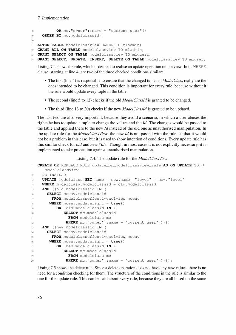
7 Implementation
8 OR mc."owner"::name = "current_user"()9 ORDER BY mc.modelclassid;
10
11 ALTER TABLE modelclassview OWNER TO mladmin;12 GRANT ALL ON TABLE modelclassview TO mladmin;13 GRANT SELECT ON TABLE modelclassview TO mlguest;14 GRANT SELECT, UPDATE, INSERT, DELETE ON TABLE modelclassview TO mluser;
Listing 7.4 shows the rule, which is defined to realise an update operation on the view. In its WHEREclause, starting at line 4, are two of the three checked conditions similar:
• The first (line 4) is responsible to ensure that the changed tuples in ModelClass really are theones intended to be changed. This condition is important for every rule, because without itthe rule would update every tuple in the table.
• The second (line 5 to 12) checks if the old ModelClassId is granted to be changed.
• The third (line 13 to 20) checks if the new ModelClassId is granted to be updated.
The last two are also very important, because they avoid a scenario, in which a user abuses therights he has to update a tuple to change the values and the Id. The changes would be passed tothe table and applied there to the new Id instead of the old one as unauthorised manipulation. Inthe update rule for the ModelClassView, the new Id is not passed with the rule, so that it wouldnot be a problem in this case, but it is used to show intention of conditions. Every update rule hasthis similar check for old and new *Ids. Though in most cases it is not explicitly necessary, it isimplemented to take precaution against unauthorised manipulation.
Listing 7.4: The update rule for the ModelClassView1 CREATE OR REPLACE RULE update_on_modelclassview_rule AS ON UPDATE TO ↵
modelclassview2 DO INSTEAD3 UPDATE modelclass SET name = new.name, "level" = new."level"4 WHERE modelclass.modelclassid = old.modelclassid5 AND ((old.modelclassid IN (6 SELECT mceav.modelclassid7 FROM modelclasseffectiveaclview mceav8 WHERE mceav.updateright = true))9 OR (old.modelclassid IN (
10 SELECT mc.modelclassid11 FROM modelclass mc12 WHERE mc."owner"::name = "current_user"())))13 AND ((new.modelclassid IN (14 SELECT mceav.modelclassid15 FROM modelclasseffectiveaclview mceav16 WHERE mceav.updateright = true))17 OR (new.modelclassid IN (18 SELECT mc.modelclassid19 FROM modelclass mc20 WHERE mc."owner"::name = "current_user"())));
Listing 7.5 shows the delete rule. Since a delete operation does not have any new values, there is noneed for a condition checking for them. The structure of the conditions in the rule is similar to theone for the update rule. This can be said about every rule, because they are all based on the same
86

7.2 Implementation of the RolesMembershipView
theory (see Section 6.1). Listing 7.6 shows a typical insert right, which passes the new data to therights table. In this case it is ModelClass.
Listing 7.5: The delete rule for the ModelClassView
1 CREATE OR REPLACE RULE delete_on_modelclassview_rule AS ON DELETE TO ↵
modelclassview2 DO INSTEAD3 DELETE FROM modelclass4 WHERE modelclass.modelclassid = old.modelclassid5 AND ((old.modelclassid IN (6 SELECT mceav.modelclassid7 FROM modelclasseffectiveaclview mceav8 WHERE mceav.deleteright = true))9 OR (old.modelclassid IN (
10 SELECT mc.modelclassid11 FROM modelclass mc12 WHERE mc."owner"::name = "current_user"())));
Listing 7.6: The insert rule for the ModelClassView
1 CREATE OR REPLACE RULE insert_on_modelclassview_rule AS ON INSERT TO ↵
modelclassview2 DO INSTEAD3 INSERT INTO modelclass (modelclassid, name, "level", "owner", ↵
creationdate)4 SELECT new.modelclassid, new.name, new."level", new."owner", ↵
new.creationdate;
The same approach to test the correctness of the rules was used as for the functions to compute theeffective rights for the model classes.
7.2 Implementation of the RolesMembershipView
Listing 7.7 shows the implemented RolesMembershipView as described in Section 6.1.4. It isdeveloped to determine the membership of a role. For this information from the internal schemaof the database is used (lines 5 and 8), in fact a relation of all roles (line 5) and a relation of theirmemberships (line 7). Both are united to one relation.
Listing 7.7: The RolesMembershipView in SQL
1 CREATE OR REPLACE VIEW rolesmembershipview AS2 SELECT rolesmembership.role_name, rolesmembership.member_in3 FROM (4 SELECT enabled_roles.role_name, enabled_roles.role_name AS ↵
member_in5 FROM information_schema.enabled_roles6 UNION7 SELECT applicable_roles.grantee, applicable_roles.role_name8 FROM information_schema.applicable_roles) rolesmembership;9
10 ALTER TABLE rolesmembershipview OWNER TO mladmin;11 GRANT ALL ON TABLE rolesmembershipview TO mladmin;
87

7 Implementation
As already mentioned this view is involved in almost every query addressing an ACL table, e.g., inthe rule for a delete operation on the ParameterInterfaceView, which is described in Section 6.1.4.Since the parameter entity has no own ACL and is linked to the interface entity, the rule uses theInterfaceACL. The rule checks if a user, who is about to delete the parameter tuple, is allowed toupdate the corresponding interface tuple. Its source code is shown in Listing 7.8 and defines how themanipulation of the view is passed to the original table. The query to the view is replaced (line 2)by the query to the Parameter table (line 3), but only if the condition in line 4 to 24 is true. Firstthe deleted ParameterId is compared to the one in the parameter table, so that not all tuples areremoved. Lines 5 to 24 specify a set, of which the linked InterfaceId has to be an element topermit deletion of the parameter. This is the main part of the security mechanism. It checks if theInterfaceId about to be deleted is an element of a set of tuples where:
• the current user or a role he is member of (line 9 to 11) has a granted UpdateRight in theACL for the corresponding interface (line 6 to 12),
• subtracting all tuples the current user or a role he is member of (line 16 to 19) has a deniedUpdateRight in the ACL for the corresponding interface (line 14 to 20).
In case that the current user is the owner of the interface, the delete operation of the parameter tupleis also allowed (line 21 to 24).
Listing 7.8: SQL source code of the rule for an delete on the ParameterInterfaceView1 CREATE OR REPLACE RULE delete_on_parameterinterfaceview_rule AS ON ↵
DELETE TO parameterinterfaceview2 DO INSTEAD3 DELETE FROM parameter4 WHERE parameter.parameterid = old.parameterid5 AND ((old.interfaceid IN (6 SELECT ia.interfaceid7 FROM interfaceacl ia8 WHERE (ia.rolename IN (9 SELECT a.member_in
10 FROM rolesmembershipview a11 WHERE "current_user"() = a.role_name::name))12 AND ia.updateright = true13 EXCEPT14 SELECT ia.interfaceid15 FROM interfaceacl ia16 WHERE (ia.rolename IN (17 SELECT a.member_in18 FROM rolesmembershipview a19 WHERE "current_user"() = a.role_name::name))20 AND ia.updateright = false))21 OR (old.interfaceid IN (22 SELECT i.interfaceid23 FROM interface i24 WHERE i."owner"::name = "current_user"())));
The two listings of this section represent the typical use of the RolesMembershipView in a commonrule for manipulating a view. Further source code will not be presented here, because the structureof rules is repetitive and thus would not provide much benefit. Instead, a scenario to test thecorrectness of the functionality of the RolesMemberShipView in the use of a rule is described.
88
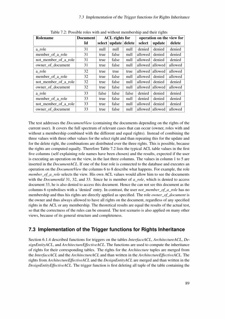
7.3 Implementation of the Trigger functions for Rights Inheritance
Table 7.2: Possible roles with and without membership and their rightsRolename Document ACL rights for operation on the view for
Id select update delete select update deletea_role 31 null null null denied denied deniedmember_of_a_role 31 true false null allowed denied deniednot_member_of_a_role 31 true false null allowed denied deniedowner_of_document 31 true false null allowed allowed alloweda_role 32 true true true allowed allowed allowedmember_of_a_role 32 true false null allowed denied allowednot_member_of_a_role 32 true false null allowed denied deniedowner_of_document 32 true false null allowed allowed alloweda_role 33 false false false denied denied deniedmember_of_a_role 33 true false null denied denied deniednot_member_of_a_role 33 true false null allowed denied deniedowner_of_document 33 true false null allowed allowed allowed
The test addresses the DocumentView (containing the documents depending on the rights of thecurrent user). It covers the full spectrum of relevant cases that can occur (owner, roles with andwithout a membership combined with the different and equal rights). Instead of combining thethree values with three other values for the select right and than repeating this for the update andfor the delete right, the combinations are distributed over the three rights. This is possible, becausethe rights are computed equally. Therefore Table 7.2 lists the typical ACL table values in the firstfive columns (self explaining role names have been chosen) and the results, expected if the useris executing an operation on the view, in the last three columns. The values in column 1 to 5 areinserted in the DocumentACL. If one of the four role is connected to the database and executes anoperation on the DocumentView the columns 6 to 8 describe what happens. For example, the rolemember_of_a_role selects the view. His own ACL values would allow him to see the documentswith the DocumentId 31, 32, and 33. Since he is member of a_role, which is denied to accessdocument 33, he is also denied to access this document. Hence the can not see this document as thecolumns 6 symbolises with a ‘denied’ entry. In contrast, the user not_member_of_a_role has nomembership and thus his rights are directly applied as specified. The role owner_of_document isthe owner and thus always allowed to have all rights on the document, regardless of any specifiedrights in the ACL or any membership. The theoretical results are equal the results of the actual test,so that the correctness of the rules can be ensured. The test scenario is also applied on many otherviews, because of its general structure and completeness.
7.3 Implementation of the Trigger functions for Rights Inheritance
Section 6.1.4 described functions for triggers on the tables InterfaceACL, ArchitectureACL, De-signEntityACL, and ArchitectureEffectiveACL. The functions are used to compute the inheritanceof rights for their corresponding tables. The rights for the Architecture tuples are merged fromthe InterfaceACL and the ArchitectureACL and than written in the ArchitectureEffectiveACL. Therights from ArchitectureEffectiveACL and the DesignEntityACL are merged and than written in theDesignEntityEffectiveACL. The trigger function is first deleting all tuple of the table containing the
89

7 Implementation
Table 7.3: Results of the performance test of the triggersNumber of tuples Operation on the tuplesin the InterfaceACL (avg. time per statement in ms)
update insert delete50 43 39 40100 62 68 61200 142 113 120300 1942 1529 1441500 5142 4823 5088750 8461 7616 6529
effective rights and than merging them new. The source code of the function and the trigger is notput in this section to not overload it with long code snippets. It can be found in the Appendix A.2Instead it is intended to show results of the performance tests of the functions. The test ran on a PCwith 1 GB RAM and a 3 GHz Pentium 4 processor with 1 MB cache.
These tests are based on a kind of worst case scenario. This means that all manipulationoperations (update, insert, delete), which fire the trigger, are executed on the InterfaceACL. Thisaffects the recomposition of the rights in the ArchitectureEffectiveACL, which is than automaticallytriggering the recomposition of rights in the DesignEntityEffectiveACL. This leads to a maximum ofworkload. The Table 7.3 lists the results of the tests. Therein the average time in milliseconds (outof 20 iterations) of a statement is listed for every operation. The operations are executed on 50,100, 200, 300, 500, and 750 tuples. The jump of time between 200 and 300 tuples is quite highcompared to the one afterwards. It can be explained through the use of indexes and the optimisation,which is part of PostgreSQL’s internal query computation. It is applied once a certain number oftuples is involved in a query. The conclusion from the test is that the system performs acceptable upto 500 tuples in the InterfaceACL relation. The decreasing performance is a result of the simplicityof the trigger function algorithm, because first all tuples of the effective rights table are deleted andthen rebuild. The development of a better algorithm, which is only re-composing tuples affectedfrom a change instead of all, is intended as part of the future work.
Usually, the implementation is followed by the testing of components, the integration testing,and the deployment of the complete application. Due to the given reasons, this has to be done oncethe application is completed.
90

8 Conclusions and Outlook
The thesis at hand is entitled “Development of a Web-Based Application for Collecting Modelsand Supporting the Design of AMS Hardware Systems”. The title indicates that it addresses topicsof software engineering as well as topics of electrical engineering, though the focus is clearlyon the software engineering side. The intended goal to develop a complete running system withthe functionality as described in Chapter 4 could not be reached. The reasons therefore are thecomplexity in the realisation of certain requirements, which occupied the major part of this work.After the decision for a N-tier architecture and for Java EE technology, which is described inChapter 5, the project management decided to concentrate on the security issues first to reach astable state in the database. Especially the realisation of a tuple-wise access control mechanism inthe meta information database, which has the highest priority of the requirements, are part of thecurrent version. The Chapters 6 and 7 described the design and the implementation of the accesscontrol in detail, though it was not possible cover every aspect in detail. The applied solutions inthe database completely provide the required fine grained access control mechanism, so that thedesign and implementation of the business and presentation tier are able to build on that. Altogetherthis thesis contribute an important part to the ModelLib system.
The next step in the development of the Web-based application are the realisation of the businessand presentation tiers. This addresses the other requirements, which are not implemented yet.Thereby, the implementation of the application logic with Session Beans is one task. Another oneis the object-relational mapping with a persistence manager and Entity Beans. This allows a directcoupling between the database and the Entity Beans, so that the use of SQL statements wouldbecome unnecessary. Furthermore, the use of JSF for the GUI could ease the implementation of areview process for new model information. They allow a validation of input data in combinationwith special error messages or pages. For example, JSF pages process a syntactical validation anda Bean processes the semantical validation. Both use the same error pages to show the results ofthe validation. The development of a keyword search is an open issue as well as the connection toEDA tools. For the latter the use of remote interfaces of Session Beans are a promising approach tostart with. An external tool is able to communicate with the Beans via the remote interface as if itis part of the system. This would enable the tool to use the application logic in the business tierdirectly. Though, it might be necessary to develop additional Beans to interact with the EDA tools,depending on how a tool interaction differs from a human user interaction.
Another task is the unification of the user account management. At the moment the database,the Subversion repository, and the Wiki platform use independent account management. In thefuture, the security of the GlassFish server as well as the Java version of the Wiki should use thePostgreSQL account information via coupling to JavaSecurity.
The current version of the ModelLib meta information database stores structural informationsabout models (how a model is build). It is intended to store also semantical meta information (Howa model can be used). Once a database schema is developed for this, the view/rule system has to beextended to the new tables to benefit from the fine grained access control mechanism.
91

8 Conclusions and Outlook
92
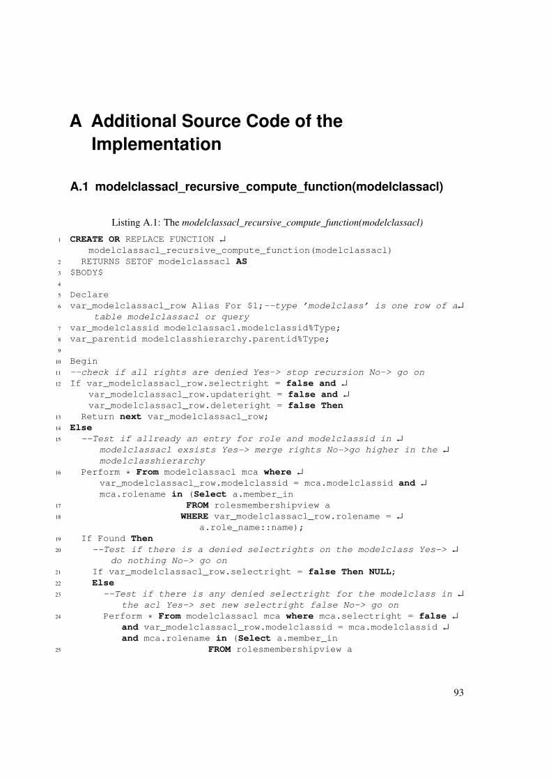
A Additional Source Code of theImplementation
A.1 modelclassacl_recursive_compute_function(modelclassacl)
Listing A.1: The modelclassacl_recursive_compute_function(modelclassacl)
1 CREATE OR REPLACE FUNCTION ↵
modelclassacl_recursive_compute_function(modelclassacl)2 RETURNS SETOF modelclassacl AS3 $BODY$4
5 Declare6 var_modelclassacl_row Alias For $1;--type ’modelclass’ is one row of a↵
table modelclassacl or query7 var_modelclassid modelclassacl.modelclassid%Type;8 var_parentid modelclasshierarchy.parentid%Type;9
10 Begin11 --check if all rights are denied Yes-> stop recursion No-> go on12 If var_modelclassacl_row.selectright = false and ↵
var_modelclassacl_row.updateright = false and ↵
var_modelclassacl_row.deleteright = false Then13 Return next var_modelclassacl_row;14 Else15 --Test if allready an entry for role and modelclassid in ↵
modelclassacl exsists Yes-> merge rights No->go higher in the ↵
modelclasshierarchy16 Perform * From modelclassacl mca where ↵
var_modelclassacl_row.modelclassid = mca.modelclassid and ↵
mca.rolename in (Select a.member_in17 FROM rolesmembershipview a18 WHERE var_modelclassacl_row.rolename = ↵
a.role_name::name);19 If Found Then20 --Test if there is a denied selectrights on the modelclass Yes-> ↵
do nothing No-> go on21 If var_modelclassacl_row.selectright = false Then NULL;22 Else23 --Test if there is any denied selectright for the modelclass in ↵
the acl Yes-> set new selectright false No-> go on24 Perform * From modelclassacl mca where mca.selectright = false ↵
and var_modelclassacl_row.modelclassid = mca.modelclassid ↵
and mca.rolename in (Select a.member_in25 FROM rolesmembershipview a
93

A Additional Source Code of the Implementation
26 WHERE var_modelclassacl_row.rolename = ↵
a.role_name::name);27 If Found Then28 var_modelclassacl_row.selectright = false;29 Else30 --Test if there are any selectrights granted on the modelclass↵
Yes -> set new selectright true No-> do nothing31 Perform * From modelclassacl mca where mca.selectright =true ↵
and var_modelclassacl_row.modelclassid = mca.modelclassid ↵
and mca.rolename in (Select a.member_in32 FROM rolesmembershipview a33 WHERE var_modelclassacl_row.rolename = ↵
a.role_name::name);34 If Found Then35 var_modelclassacl_row.selectright = true;36 End if; --new selectright granted37 End if; --new selectright denied38 End if; --old selectright denied39 --40 --Test if there is a denied updaterights on the modelclass Yes-> ↵
do nothing No-> go on41 If var_modelclassacl_row.updateright = false Then NULL;42 Else43 --Test if there is any denied updateright for the modelclass in ↵
the acl Yes-> set new updateright false No-> go on44 Perform * From modelclassacl mca where mca.updateright = false ↵
and var_modelclassacl_row.modelclassid = mca.modelclassid ↵
and mca.rolename in (Select a.member_in45 FROM rolesmembershipview a46 WHERE var_modelclassacl_row.rolename = ↵
a.role_name::name);47 If Found Then48 var_modelclassacl_row.updateright = false;49 Else50 --Test if there are any updaterights granted on the modelclass↵
Yes -> set new updateright true No-> do nothing51 Perform * From modelclassacl mca where mca.updateright =true ↵
and var_modelclassacl_row.modelclassid = mca.modelclassid ↵
and mca.rolename in (Select a.member_in52 FROM rolesmembershipview a53 WHERE var_modelclassacl_row.rolename = ↵
a.role_name::name);54 If Found Then55 var_modelclassacl_row.updateright = true;56 End if; --new updateright granted57 End if; --new updateright denied58 End if; --old updateright denied59 --60 --Test if there is a denied deleterights on the modelclass Yes-> ↵
do nothing No-> go on61 If var_modelclassacl_row.deleteright = false Then NULL;62 Else
94

A.1 modelclassacl_recursive_compute_function(modelclassacl)
63 --Test if there is any denied deleteright for the modelclass in ↵
the acl Yes-> set new deleteright false No-> go on64 Perform * From modelclassacl mca where mca.deleteright = false ↵
and var_modelclassacl_row.modelclassid = mca.modelclassid ↵
and mca.rolename in (Select a.member_in65 FROM rolesmembershipview a66 WHERE var_modelclassacl_row.rolename = ↵
a.role_name::name);67 If Found Then68 var_modelclassacl_row.deleteright = false;69 Else70 --Test if there are any deleterights granted on the modelclass↵
Yes -> set new deleteright true No-> do nothing71 Perform * From modelclassacl mca where mca.deleteright =true ↵
and var_modelclassacl_row.modelclassid = mca.modelclassid ↵
and mca.rolename in (Select a.member_in72 FROM rolesmembershipview a73 WHERE var_modelclassacl_row.rolename = ↵
a.role_name::name);74 If Found Then75 var_modelclassacl_row.deleteright = true;76 End if; --new deleteright granted77 End if; --new deleteright denied78 End if; --old deleteright denied79
80 --go up in modelclasshierarchy81 --Test if the modelclass has a parent note Yes-> go up and use ↵
current value of a modelclassacl row for next iteration82 Perform * From modelclasshierarchy mch where mch.childid = ↵
var_modelclassacl_row.modelclassid;83 If Found Then84 var_modelclassid = var_modelclassacl_row.modelclassid; --stores ↵
current modelclassid in a var so that it get not lost85 --get parent modelclassid and access function with it86 Select Into var_modelclassacl_row.modelclassid mch.parentid From↵
modelclasshierarchy mch where ↵
var_modelclassacl_row.modelclassid = mch.childid;87 Select Into var_modelclassacl_row * From ↵
modelclassacl_recursive_compute_function(var_modelclassacl_row);88 var_modelclassacl_row.modelclassid := var_modelclassid; --write ↵
the original modelclassid back in the result of effective ↵
rights computation89 Else90 return next var_modelclassacl_row;91 End if; --parent note test92 Else93 --go up in modelclasshierarchy94 --Test if the modelclass has a parent note Yes-> go up and use ↵
current value of a modelclassacl row for next iteration95 Perform * From modelclasshierarchy mch where mch.childid = ↵
var_modelclassacl_row.modelclassid;96 If Found Then
95

A Additional Source Code of the Implementation
97 var_modelclassid = var_modelclassacl_row.modelclassid; --stores ↵
current modelclassid in a var so that it get not lost98 --get parent modelclassid and access function with it99 var_parentid = mch.parentid From modelclasshierarchy mch where ↵
mch.childid = var_modelclassacl_row.modelclassid;100 var_modelclassacl_row.modelclassid = var_parentid;101 Select Into var_modelclassacl_row * From ↵
modelclassacl_recursive_compute_function(var_modelclassacl_row);102 var_modelclassacl_row.modelclassid := var_modelclassid; --write ↵
the original modelclassid back in the result of effective ↵
rights computation103 Else104 return next var_modelclassacl_row;105 End if; --parent note test106 End if; --Test for exsisting acl entry107 Return next var_modelclassacl_row;108 End if; --total deny109 return;110 End;111 $BODY$112 LANGUAGE ’plpgsql’ VOLATILE SECURITY DEFINER;113 ALTER FUNCTION ↵
modelclassacl_recursive_compute_function(modelclassacl) OWNER TO ↵
mladmin;114 GRANT EXECUTE ON FUNCTION ↵
modelclassacl_recursive_compute_function(modelclassacl) TO mladmin;115 GRANT EXECUTE ON FUNCTION ↵
modelclassacl_recursive_compute_function(modelclassacl) TO public;
A.2 Trigger Function and Trigger
Listing A.2: The trigger function to compose the ArchitectureEffectiveACL
1 CREATE OR REPLACE FUNCTION architecture_effective_rights_computation()2 RETURNS "trigger" AS3 $BODY$4 Declare5 Begin6 DELETE FROM architectureeffectiveacl;7 INSERT INTO architectureeffectiveacl SELECT ia.rolename, ↵
a.architectureid, ia.selectright, ia.updateright, ia.deleteright8 FROM interfaceacl ia, interface i, designentity de, architecture a9 WHERE ia.interfaceid = i.interfaceid
10 AND i.interfaceid = de.interfaceid11 AND de.architectureid = a.architectureid12 AND NOT (a.architectureid IN (13 SELECT aa.architectureid14 FROM architectureacl aa))15 UNION16 SELECT aa.rolename, aa.architectureid, aa.selectright, ↵
aa.updateright, aa.deleteright17 FROM architectureacl aa;18 Return NULL;
96

A.3 ModelLib Database Tables
19 End;20 $BODY$
Listing A.3: The trigger on the InterfaceACL
1 CREATE TRIGGER architectureeffectiverightstrigger2 AFTER INSERT OR UPDATE OR DELETE3 ON interfaceacl4 FOR EACH STATEMENT5 EXECUTE PROCEDURE architecture_effective_rights_computation();
A.3 ModelLib Database Tables
Table A.1: List of all tables in the meta information database
Table name Rights for basic roles Related views andtables (not in the ERD)
Architecture mladmin all ArchitectureViewmluser – ArchitectureEffectiveACLmlguest – DesignentityEffectiveACL
ArchitectureACLViewArchitectureAssertionView (via rule)PrameterArchitectureView (via rule)ArchitectureDocumentView (via rule)AssertionView (via rule)
ArchitectureACL mladmin all architectureaclviewmluser – architectureviewmlguest – ArchitectureEffectiveACL
ArchitectureAssertion mladmin all ArchitectureAssertionviewmluser – AssertionViewmlguest –
ArchitectureDocument mladmin all ArchitectureDocumentViewmluser –mlguest –
ArchitectureEffectiveACL mladmin all ArchitectureViewmluser – DesignentityEffectiveACLmlguest – ArchitectureAssertionView (via rule)
ArchitectureDocumentView (via rule)AssertionView (via rule)ParameterArchitectureView (via rule)
ArchitectureParameter mladmin all ParameterArchitectureViewmluser –mlguest –
Assertion mladmin all AssertionViewmluser –mlguest –
Rights: (S)elect, (U)pdate, (I)nsert, (D)elete
97

A Additional Source Code of the Implementation
Table name Rights for basic roles Related views andtables (not in the ERD)
Author mladmin all ArchitectureDocumentViewmluser – AuthorViewmlguest –
DesignEntity mladmin all ArchitectureEffectiveACLmluser – DesignentityEffectiveACLmlguest – ArchitectureView
DesignEntityViewDesignEntityACLView (via rule)DesignEntityDependencyView (via rule)DesignEntityDocumentView (via rule)DesignEntityFileView (via rule)DesignEntityLicenseView (via rule)TestbenchDesignEntityView (via rule)
DesignEntityACL mladmin all DesignentityEffectiveACLmluser – DesignEntityACLViewmlguest – DesignEntityView
TestbenchDesignEntityViewDesignEntityDependency mladmin all DesignEntityDependencyView
mluser –mlguest –
DesignEntityDocument mladmin all DesignEntityDocumentViewmluser –mlguest –
DesignEntityEffectiveACL mladmin all DesignEntityViewmluser – DesignEntityDependencyView (via rule)mlguest – DesignEntityDocumentView (via rule)
DesignEntityFileView (via rule)DesignEntityLicenseView (via rule)TestbenchDesignEntityView (via rule)
DesignEntityFile mladmin – DesignEntityFileViewmluser – FileViewmlguest –
DesignEntityLicense mladmin all DesignEntityLicenseViewmluser –mlguest –
DesignEntityMessage mladmin all DesignEntityMessageViewmluser –mlguest –
Designlanguage mladmin all DesignLanguageVersionViewmluser Smlguest S
DesignLanguageVersion mladmin all DesignLanguageVersionViewmluser S DesignEntityView
Rights: (S)elect, (U)pdate, (I)nsert, (D)elete
98
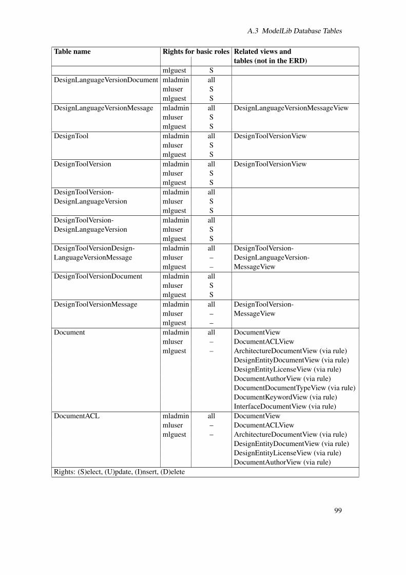
A.3 ModelLib Database Tables
Table name Rights for basic roles Related views andtables (not in the ERD)
mlguest SDesignLanguageVersionDocument mladmin all
mluser Smlguest S
DesignLanguageVersionMessage mladmin all DesignLanguageVersionMessageViewmluser Smlguest S
DesignTool mladmin all DesignToolVersionViewmluser Smlguest S
DesignToolVersion mladmin all DesignToolVersionViewmluser Smlguest S
DesignToolVersion- mladmin allDesignLanguageVersion mluser S
mlguest SDesignToolVersion- mladmin allDesignLanguageVersion mluser S
mlguest SDesignToolVersionDesign- mladmin all DesignToolVersion-LanguageVersionMessage mluser – DesignLanguageVersion-
mlguest – MessageViewDesignToolVersionDocument mladmin all
mluser Smlguest S
DesignToolVersionMessage mladmin all DesignToolVersion-mluser – MessageViewmlguest –
Document mladmin all DocumentViewmluser – DocumentACLViewmlguest – ArchitectureDocumentView (via rule)
DesignEntityDocumentView (via rule)DesignEntityLicenseView (via rule)DocumentAuthorView (via rule)DocumentDocumentTypeView (via rule)DocumentKeywordView (via rule)InterfaceDocumentView (via rule)
DocumentACL mladmin all DocumentViewmluser – DocumentACLViewmlguest – ArchitectureDocumentView (via rule)
DesignEntityDocumentView (via rule)DesignEntityLicenseView (via rule)DocumentAuthorView (via rule)
Rights: (S)elect, (U)pdate, (I)nsert, (D)elete
99

A Additional Source Code of the Implementation
Table name Rights for basic roles Related views andtables (not in the ERD)DocumentDocumentTypeView (via rule)DocumentKeywordView (via rule)InterfaceDocumentView (via rule)
DocumentAuthor mladmin all DocumentAuthorViewmluser –mlguest –
DocumentDocumentType mladmin all DocumentDocumentTypeViewmluser –mlguest –
DocumentKeyword mladmin all DocumentKeywordViewmluser –mlguest –
DocumentMessage mladmin all DocumentMessageViewmluser –mlguest –
DocumentType mladmin allmluser Smlguest S
File mladmin all FileViewmluser – FileACLViewmlguest – DesignEntityFileView (via rule)
FileDesignToolVersionView (via rule)FileACL mladmin all FileView
mluser – FileACLViewmlguest – DesignEntityFileView (via rule)
FileDesignToolVersion mladmin all FileDesignTool-mluser – VersionViewmlguest –
Interface mladmin all ArchitectureEffectiveACLmluser – InterfaceViewmlguest – InterfaceACLView
ModelClassInterfaceViewAssertionView (via rule)InterfaceAssertionView (via rule)InterfaceKeywordView (via rule)ParameterInterfaceView (via rule)Portview (via rule)
InterfaceACL mladmin all ArchitectureEffectiveACLmluser – InterfaceViewmlguest – InterfaceACLView
AssertionView (via rule)ModelClassInterfaceView (via rule)InterfaceAssertionView (via rule)
Rights: (S)elect, (U)pdate, (I)nsert, (D)elete
100

A.3 ModelLib Database Tables
Table name Rights for basic roles Related views andtables (not in the ERD)InterfaceDocumentView (via rule)InterfaceKeywordView (via rule)ParameterInterfaceView (via rule)Portview (via rule)
InterfaceAssertion mladmin all AssertionViewmluser – InterfaceAssertionViewmlguest –
InterfaceDocument mladmin all InterfaceDocumentViewmluser –mlguest –
InterfaceKeyword mladmin all InterfaceKeywordViewmluser –mlguest –
InterfaceParameter mladmin all ParameterInterfaceViewmluser –mlguest –
Keyword mladmin allmluser S Imlguest S
Message mladmin all MessageViewmluser – DesignEntityMessageViewmlguest – (via rule)
DesignLanguageVersion-MessageView (via rule)DesignToolVersionDesign-LanguageVersionMessageView (via rule)
ModelClass mladmin all ModelClassACLViewmluser S ModelClassViewmlguest S ModelClassInterfaceView
ModelClassHierarchyView (via rule)ModelClassKeywordView (via rule)
ModelClassACL mladmin all ModelClassACLViewmluser – ModelClassViewmlguest –
ModelClassHierarchy mladmin all ModelClassHierarchyViewmluser Smlguest S
ModelClassInterface mladmin all InterfaceViewmluser – ModelClassInterfaceViewmlguest –
ModelClassKeyword mladmin all ModelClassKeywordViewmluser –mlguest –
Rights: (S)elect, (U)pdate, (I)nsert, (D)elete
101

A Additional Source Code of the Implementation
Table name Rights for basic roles Related views andtables (not in the ERD)
Parameter mladmin all ParameterArchitectureViewmluser – ParameterInterfaceViewmlguest –
Port mladmin all PortViewmluser – ParameterInterfaceViewmlguest –
PortClass mladmin all PortViewmluser Smlguest S
PortDirection mladmin all PortViewmluser Smlguest S
Severity mladmin all AssertionViewmluser Smlguest S
TestbenchDesignEntity mladmin all TestbenchDesignEntityViewmluser –mlguest –
UserDirectory mladmin all UserDirectoryViewmluser –mlguest –
Vendor mladmin all DesignToolVersionViewmluser Smlguest S
Rights: (S)elect, (U)pdate, (I)nsert, (D)elete
A.4 ModelLib Database Views
Table A.2: List of all views in the meta information database
View name Rights for basic roles Related views andtables
ArchitectureACLView mladmin allmluser S U I Dmlguest –
ArchitectureAssertionView mladmin allmluser S U I Dmlguest S
ArchitectureDocumentView mladmin allmluser S U I Dmlguest S
ArchitectureView mladmin all ArchitectureAssertionViewmluser S U I D ArchitectureDocumentView
Rights: (S)elect, (U)pdate, (I)nsert, (D)elete
102

A.4 ModelLib Database Views
View name Rights for basic roles Related views andtables
mlguest S AssertionViewDesignEntityViewParameterArchitectureView
AssertionView mladmin allmluser S U I Dmlguest S
AuthorView mladmin allmluser S U I Dmlguest S
DesignEntityACLView mladmin allmluser S U I Dmlguest –
DesignEntityDependencyView mladmin allmluser S U I Dmlguest S
DesignEntityDocumentView mladmin allmluser S U I Dmlguest S
DesignEntityFileView mladmin allmluser S U I Dmlguest S
DesignEntityLicenseView mladmin allmluser S U I Dmlguest S
DesignEntityMessageView mladmin allmluser S U I Dmlguest S
DesignEntityView mladmin all DesignEntity-mluser S U I D DependencyViewmlguest S DesignEntityDocumentView
FileViewDesignEntityFileViewDesignEntityLicenseViewDesignEntityMessageViewTestbenchDesignEntityView
DesignLanguage- mladmin allVersionMessageView mluser S U I D
mlguest SDesignLanguageVersionView mladmin all DesignEntityView
mluser Smlguest S
DesignToolVersion- mladmin allDesignLanguageVersion- mluser S U I DRights: (S)elect, (U)pdate, (I)nsert, (D)elete
103

A Additional Source Code of the Implementation
View name Rights for basic roles Related views andtables
MessageView mlguest SDesignToolVersion- mladmin allMessageView mluser S U I D
mlguest SDesignToolVersionView mladmin all
mluser Smlguest S
DocumentACLView mladmin allmluser S U I Dmlguest –
DocumentAuthorView mladmin allmluser S U I Dmlguest S
Document- mladmin allDocumentTypeView mluser S U I D
mlguest SDocumentKeywordView mladmin all
mluser S U I Dmlguest S
DocumentMessageView mladmin allmluser S U I Dmlguest S
DocumentView mladmin all ArchitectureDocumentViewmluser S U I D DesignEntitsDocumentViewmlguest S DesignEntity-
LicenseViewDocument-DocumentTypeViewDocumentKeywordViewDocumentMessageViewInterfaceDocumentView
FileACLView mladmin allmluser S U I Dmlguest –
FileDesignTool- mladmin allVersionView mluser S U I D
mlguest SFileView mladmin all DesignEntityFileView
mluser S U I D FileDesignTool-mlguest S VersionView
InterfaceACLView mladmin allmluser S U I Dmlguest –
Rights: (S)elect, (U)pdate, (I)nsert, (D)elete
104

A.4 ModelLib Database Views
View name Rights for basic roles Related views andtables
InterfaceAssertionView mladmin allmluser S U I Dmlguest S
InterfaceDocumentView mladmin allmluser S U I Dmlguest S
InterfaceKeywordView mladmin allmluser S U I Dmlguest S
InterfaceView mladmin all ArchitectureViewmluser S U I D AssertionViewmlguest S DesignEntityView
InterfaceAssertionViewInterfaceDocumentViewInterfaceKeywordViewModelClassInterfaceViewParameterInterfaceViewPortView
MessageView mladmin allmluser S U I Dmlguest S
ModelClassACLView mladmin allmluser S U I Dmlguest –
ModelClassEffectiveACLView mladmin all InterfaceViewmluser S ModelClassViewmlguest – ModelClassHierarchy-
View (via rule)ModelClassInterface-View (via rule)ModelClassKeyword-View (via rule)
ModelClassHierarchyView mladmin allmluser S U I Dmlguest S
ModelClassInterfaceView mladmin allmluser S U I Dmlguest S
ModelClassKeywordView mladmin allmluser S U I Dmlguest S
ModelClassView mladmin all ModelClassHierarchyViewmluser S U I D ModelClassInterfaceView
Rights: (S)elect, (U)pdate, (I)nsert, (D)elete
105

A Additional Source Code of the Implementation
View name Rights for basic roles Related views andtables
mlguest S ModelClassKeywordViewParameterArchitectureView mladmin all
mluser S U I Dmlguest S
ParameterInterfaceView mladmin allmluser S U I Dmlguest S
PortView mladmin allmluser S U I Dmlguest S
RolesMembershipView mladmin all see Table A.3mluser –mlguest –
Testbench- mladmin allDesignEntityView mluser S U I D
mlguest SUserDirectoryView mladmin all
mluser S U I Dmlguest –
UserInformationView mladmin allmluser Smlguest S
Rights: (S)elect, (U)pdate, (I)nsert, (D)elete
106

A.4 ModelLib Database Views
Table A.3: Table of views depending on the RolesMembershipViewViews depending on the RolesMembershipViewInterfaceViewArchitectureViewDocumentViewDesignEntityViewFileViewArchitectureAssertionViewArchitectureDocumentViewAssertionViewDesignEntityDependencyViewDesignEntityDocumentViewDesignEntityFileViewDesignEntityLicenseViewDesignEntityDocumentViewDocumentAuthorViewDocumentDocumentTypeViewDocumentKeywordViewFileDesignToolVersionViewInterfaceAssertionViewInterfaceDocumentViewInterfaceKeywordViewModelClassInterfaceViewParameterArchitectureViewParameterInterfaceViewPortViewTestbenchDesignEntityView
107

A Additional Source Code of the Implementation
108
Bibliography
[Acc04] Accellera: Verilog-AMS Language Reference Manual Version 2.2—Analog & Mixed-Signal Extensions to Verilog HDL, 2004. http://www.eda.org/verilog-ams/htmlpages/public-docs/lrm/2.2/AMS-LRM-2-2.pdf.
[Bel00] Bell, Douglas: Software Engineering – A Programming Approach. Pearson Education,Harlow, UK, 3rd edition, 2000.
[BHR07] Bartetzko, Detlef, Arvid Hülsebus und Lars Röwekamp: Im Angesicht des Web.iX SPEZIAL, Seiten 111–130, Januar 2007. http://www.ix.de, besucht: 11. 01. 2007.
[BMH06] Burke, Bill and Richard Monson-Haefel: Enterprise JavaBeans 3.0. O’Reilly Media,Sebastopol, US, 5th edition, May 2006.
[CFMS95] Castano, Silvana, Maria Grazia Fugini, Giancarlo Martellan, and Pierangela Samarati:Database Security. ACM Press, New York, US, 1st edition, 1995.
[CK03] Crawford, William and Jonathan Kaplan: J2EE Design Patterns. O’Reilly Media,Sebastopol, US, 1st edition, September 2003.
[CSFP04] Collins-Sussman, Ben, Brian W. Fitzpatrick, and C. Michael Pilato: Version Controlwith Subversion. O’Reilly Media, Inc., Sebastopol, USA, 1st edition, June 2004.http://svnbook.red-bean.com/, visited on 27/03/2006.
[DLWZ03] Dumke, Reiner, Mathias Lother, Cornelius Wille und Fritz Zbrog: Web Engineering.Pearson Studium, München, 1. Auflage, 2003. http://se.cs.uni-magdeburg.de/,besucht: 16. 08. 2006.
[Dum03] Dumke, Reiner: Software Engineering. Vieweg Verlag, Wiesbaden, 4. Auflage, 2003.http://se.cs.uni-magdeburg.de/, besucht: 16. 08. 2006.
[Ein05] Einwich, Karsten: Application of SystemC/SystemC-AMS for the specification of acomplex wired telecommunication system. In Proceedings of the 8th InternationalForum on Specification & Design Languages (FDL) 2005, pages 49–60, EPFL,Lausanne, Switzerland, September 27–30 2005. ECSI.
[FC05] Farley, Jim and William Crawford: Java Enterprise – in a Nutschell. O’Reilly Media,Sebastopol, US, 3rd edition, November 2005.
[Her04] Hertel, Frank: Entwicklung einer datenbankgestützten Nutzerverwaltungs- und Zu-griffsrechtekomponente als Middleware zwischen Web-Applikationen und molekular-biologischen Datenbanken. Studienarbeit, Otto-von-Guericke Universität Magdeburg,Magdeburg, 19. April 2004.
[Hor06] Horn, Torsten: SQL Grundlagen – Vergleich MySQL, PostgreSQL und MaxDB, Au-gust 1998–2006. http://www.torsten-horn.de/techdocs/sql.htm, besucht: 11. 08. 2006.
109

Bibliography
[HS97] Heuer, Andreas und Gunter Saake: Datenbanken – Konzepte und Sprachen. Interna-tional Thomson Publishing, Bonn, 2. Auflage, 1997.
[IEE01] IEEE 1076.1 Working Group: IEEE Standard 1076.1-1999, IEEE Standard VHDLAnalog and Mixed-Signal Extensions, 2001. http://standards.ieee.org/reading/ieee/std/dasc/1076.1-1999.pdf, visited on 08/09/2006.
[Jav06] Sun Microsystems: Java EE Downloads, 1994–2006. http://java.sun.com/javaee/downloads/index.jsp, visited on 17/07/2006.
[JBC+06] Jendrock, Eric, Jennifer Ball, Debbie Carson, Ian Evans, Scott Fordin, and Kim Haase:The Java EE 5 Tutorial – For Sun Java System Application Server Platform Edition 9.Sun Microsystems, September 2006. http://java.sun.com/javaee/5/docs/tutorial/doc/,visited on 27/09/2006.
[Jon05] Jones, Paul M.: YaWiki: Yet Another Wiki for PHP, 2005. http://www.yawiki.com/,visited on 27/03/2006.
[Kec05] Kecher, Christoph: UML-2.0 – Das umfassende Handbuch. Galileo Press GmbH,Bonn, 2005.
[KMP+04] Kappel, Gerti, Elke Michlmayr, Birgit Pröll, Siegfried Reich, and Werner Retschitzeg-ger: Web engineering – old wine in new bottles? In Koch, N., P. Fraternale, andM. Wirsing (editors): Web Engineering 4th International Conference, ICWE 2004,Munich, Germany, July 26-30, 2004, Proceedings, volume 3140 of Lecture Notes inComputer Science, pages 6–12, Berlin, Heidelberg, July 2004. Springer.
[KPRR06] Kappel, Gerti, Birgit Pröll, Siegfried Reich, and Werner Retschitzegger: Web Engi-neering – The Discipline of Systematic Development of Web Application. John Wileyand Sons, Chichester, UK, 1st edition, May 2006.
[KS06] Keith, Mike and Merrick Schincariol: Pro EJB 3 – Java Persistence API. Apress,Berkeley, US, 1st edition, 2006.
[MV06] Mähne, Torsten and Alain Vachoux: ModelLib: A web-based platform for col-lecting behavioural models and supporting the design of ams systems. In Fo-rum on Specification and Design Languages (FDL) 2006. ECSI, September 2006.http://infoscience.epfl.ch/search.py?recid=88137, visited on 08/08/2006.
[MyS06] MySQL AB: MySQL: The World’s Most Popular Open Source Database, 1995–2006.http://www.mysql.com/, visited on 27/03/2006.
[Mä06] Mähne, Torsten: ModelLib prototype, July 2006. https://lsmpc4.epfl.ch/modellib/,visited on 13/07/2006.
[Obj05] Object Management Group: Unified Modeling Language: Superstructure, version2.0 edition, Aug 2005. http://www.omg.org/technology/documents/formal/uml.htm,visited on 24/08/2006.
[OTDRG05] O’Connor, I., F. Tissafi-Drissi, G. Révy, and F. Gaffiot: UML/XML-based ap-proach to hierarchical AMS synthesis. In Forum on Specification and Design Lan-guages (FDL) 2005, pages 89–100, September 2005. http://www.ecsi.org/fdl/, visitedon 10/03/2006.
110

Bibliography
[PHP06] The PHP Group: PHP: Hypertext Preprocessor, 2001-2006. http://www.php.net/,visited on 27/03/2006.
[PLV05] Pécheux, F., C. Lallement, and A. Vachoux: VHDL-AMS and Verilog-AMS as alterna-tive hardware description languages for efficient modeling of multidiscipline systems.IEEE Transactions on Computer-Aided Design of Integrated Circuits and Systems,24:204–225, 2005.
[Pos07] PostgreSQL Global Development Group: PostgreSQL: The World’s Most AdvancedOpen Source Database, 1996–2007. http://www.postgresql.org/docs/8.2/interactive/,visited on 08/01/2007.
[Pre01] Pressman, Roger S.: Software Engineering – A Practitioner’s Approach. McGraw-Hill Higher Education, New York, USA, 5th edition, 2001.
[RV03] Rahm, Erhard und Gottfried Vossen: Web & Datenbanken. dpunkt.verlag GmbH,Heidelberg, 1. Auflage, 2003.
[Rö05] Röhrig, Bernhard: Licht ins Dickicht. Linux Magazin, Seiten 32–43, Mai 2005.http://www.linux-magazin.de/, besucht: 10. 08. 2006.
[Som01] Sommerville, Ian: Software Engineering. Pearson Education, Harlow, UK, 6th edi-tion, 2001.
[SQL06] About, Inc., A part of The New York Times Company: SQL Basics: Structured QueryLanguage (SQL), 1996–2006. http://databases.about.com/od/sql/a/sqlbasics.htm,visited on 14/12/2006.
[SST97] Saake, Gunter, Ingo Schmitt und Can Türker: Objektdatenbanken – Konzepte, Spra-chen, Architekturen. International Thomson Publishing, Bonn, 1. Auflage, 1997.
[VGE05] Vachoux, A., C. Grimm, and K. Einwich: Extending SystemC to support mixeddiscrete-continuous system modeling and simulation. In Proceedings of the IEEE In-ternational Symposium on Circuits and Systems (ISCAS) 2005, pages 5166–5169,May 23–26 2005. http://ieeexplore.ieee.org/iel5/9898/31469/01465798.pdf, visitedon 08/09/2006.
[WE06] Wieland, Joachim und Peter Eisentraut: Probeabstimmung – PostgreSQL 8.1 mitwichtigen neuen Features. Linux Magazin, Seiten 74–77, Januar 2006. http://www.linux-magazin.de/, besucht: 13. 08. 2006.
[Wik06a] Wikimedia Foundation: List of integrated development environments, Dec 2006.http://en.wikipedia.org/wiki/List_of_integrated_development_environments, visitedon 10/12/2006.
[Wik06b] Wikimedia Foundation: PHP, July 2006. http://en.wikipedia.org/wiki/PHP, visited on20/07/2006.
111

Bibliography
112

Statement
I hereby declare that I created this work alone and by using only legal means.
Lausanne, 30th January 2007
Thomas Böhm
113