development of an open-source amateur radio transceiver
TRANSCRIPT

1
Development of an Open-Source Amateur
Radio Transceiver for Small Satellites
Ricardo J. Saborío Borbón1, E. Glenn Lightsey2 Georgia Institute of Technology, Atlanta, GA, 30332, United States
The communications subsystem is a vital component of every space mission. However, the
necessary hardware and infrastructure often consumes a significant portion of the allotted
budget for a project. This poses a problem for University teams developing small satellites
with limited funds. Open-source projects like Planet’s OpenLST integrated hardware
transceiver have attempted to solve this issue. While the OpenLST project addresses the
hardware cost issue, it does not provide an affordable solution for the infrastructure problem.
In this paper, a series of firmware modifications were completed for the OpenLST transceiver
to allow for compatibility with amateur packet radio protocols. By implementing well-known
protocols like AX.25, it is possible to leverage the existing infrastructure of amateur radio to
reduce costs. The paper outlines the key differences between the existing protocol and AX.25,
how these were addressed, and the tests performed to validate the firmware modifications.
I. Abbreviations
2-FSK = Two Frequency-Shift Keying
ADC = Analog-to-Digital Converter
ASCII = American Standard Code for Information Interchange
CRC = Cyclic Redundancy Check
DMA = Direct Memory Address
EOM = End of Message
FCS = Frame Checking Sequence
FEC = Forward Error Correction
GNU = recursive acronym for “GNU’s Not Unix!”
GPIO = General Purpose Input Output
HDLC = High-level Data Link Control
HWID = Hardware Identification Number
IARU = International Amateur Radio Union
IC = Integrated Circuit
ISR = Interrupt Service Routine
KISS = “Keep It Simple, Stupid”
LSB = Least Significant Byte
LSb = Least Significant Bit
LSn = Least Significant Nibble
MCU = Microcontroller Unit
MSB = Most Significant Byte
MSb = Most Significant Bit
MSn = Most Significant Nibble
Msg = Message
NRZ(I) = Non-Return-to-Zero Inverted
NRZ(L) = Non-Return-to-Zero Level
1 Graduate student, Guggenheim School of Aerospace Engineering, [email protected]. 2 Professor, Guggenheim School of Aerospace Engineering, [email protected].

2
OSI = Open Systems Interconnection
OTA = Over-the-Air
RF = Radio Frequency
SDR = Software-Defined Radio
SOM = Start of Message
SSID = Secondary Station Identifier
TAPR = Tucson Amateur Packet Radio Corporation
TNC = Terminal Node Controller
UART = Universal Asynchronous Receive Transmit
UHF = Ultra High Frequency
II. Nomenclature
bi = i-th bit of a byte. LSb is given by zeroth bit.
Bi = i-th byte of a frame. LSB is given by zeroth byte.
X2 = base 2 number. X denotes the number. MSb is shown first.
X16 = base 16 number. X denotes the number. MSn is shown first.
III. Introduction
Small satellites have become an attractive solution for University teams looking for an affordable testbed for
mission concepts and technology demonstrations. Improvements in electronics miniaturization, and their reduced cost
when compared to larger satellite buses, have contributed to the popularity of these vehicles among smaller teams.
However, small satellites are not a universal solution to reduce the cost of a space mission. Space-grade components
come at an unavoidable premium that comprise a significant portion of a mission’s cost. This is particularly true in
the case of the communications subsystem which, in addition to the hardware costs, requires a significant additional
investment to develop the necessary ground station infrastructure.
The communications subsystem is often a vital component required for mission success. None of the mission
objectives can be achieved if the team is unable to communicate with the vehicle. Consequently, this subsystem will
often be made up of space-grade hardware with considerable space heritage. Traditionally, a team developing a small
satellite may opt to purchase both the hardware and ground station services from a third party. This provides the
benefit of flight-proven hardware and reliable ground station infrastructure. However, the service and hardware costs
will often take up a large portion of the project’s budget. Moreover, the third party hardware is often a “black box”
with non-customizable firmware that reduces the versatility of the subsystem. Likewise, teams will often have to
adhere to strict link budgets and compete for ground station time with larger missions. This severely limits the amount
of data that can be downlinked by the vehicle and might affect the success of the overall mission. Needless to say, the
third party solution is far from ideal, but the alternative of developing in-house hardware and infrastructure is often
just as expensive and a less reliable solution to the problem.
Planet attempted to address the small satellite communications issue by releasing an open-source version of the
UHF radio used in their Dove CubeSats [1]. The product, dubbed the OpenLST, is an integrated hardware transceiver
made of purely off-the-shelf components. Planet made both the firmware and hardware schematics available to the
public free of charge. OpenLST directly addressed the hardware issue by providing a flight-proven radio that can be
produced at the fraction of the cost of space-grade radios. Furthermore, the open-source nature of the firmware allows
for a high degree of customization to meet mission requirements. That being said, the OpenLST uses Planet’s
proprietary communications protocol and requires a dedicated ground station using an OpenLST receiver to
communicate with the spacecraft. Therefore, this product only partially solves the small satellite communications
issue.
The second half of the solution is provided by amateur packet radio. The amateur radio bands are highly regulated
regions of the radio frequency spectrum that have been isolated for non-commercial use. These frequencies are
overseen by the IARU and the specifics for its use, including hardware and protocol requirements, have been widely
documented to allow for compatibility with amateur radio stations worldwide [2]. One such protocol is AX.25, which
was developed for the digital transmission of data over radio waves. The longevity of amateur radio, which has been
in place since the early 1920’s, signifies that there is an existing worldwide infrastructure for its use. Therefore, if a
small satellite radio were to use an amateur packet radio protocol like AX.25, it could leverage the existing amateur

3
radio stations and remove the requirement for ground station infrastructure altogether. Anyone with a ham radio and
access to a sensitive enough receiving station should be capable of communicating with the spacecraft. Thus, a full
solution to the small satellite communications problem would combine cheap off-the-shelf flight-proven hardware,
like OpenLST, with an amateur packet radio protocol like AX.25.
This paper focuses on creating a full solution to the small satellite communications problem by modifying the
firmware of Planet’s OpenLST. The modifications are intended to replace the proprietary communications protocol
with the AX.25 amateur packet radio protocol. The key differences between the protocols will be discussed and the
necessary hardware and software modifications to address these will be outlined. Further, a preliminary version of the
firmware modifications have been implemented on the OpenLST and tested to verify the effectiveness of the solution.
IV. Hardware, Firmware, and Protocols Overview
The section that follows outlines the main features of the OpenLST hardware, as well as the key characteristics of
the OpenLST and AX.25 protocols. The protocol properties are broken down in terms of the OSI model with a focus
on the physical (layer 1) and data link (layer 2) layers [3]. The logic behind the flow of information in each protocol
is also addressed.
A. OpenLST Integrated Hardware Transceiver
The OpenLST is an integrated hardware radio based off Texas Instruments’ CC1110 Low-Power RF Transceiver
chip [4]. This IC includes an Intel 8051 MCU core that allows for onboard data processing and provides a range of
peripherals including ADCs, GPIO pins, timers, and UART ports. In addition, the chip features an onboard packet
engine that handles the detection and parsing of incoming messages in the background. This removes the need for a
dedicated parsing function in the firmware, as long as the message format adheres to the CC1110 standards. The
hardware interfaces, shown in Fig. 1, consist of two UART ports, three debug GPIO pins, and one SMA port. The
debug pins directly connect to the CC1110 modulator and allow for the observation of the incoming/outgoing
bitstream.
Fig. 1 Hardware interfaces of the OpenLST board. Image courtesy of Planet [1].
In addition to the transceiver hardware and firmware, the initial OpenLST release featured a Python ground station
toolbox to interface with the radio. This included custom commands to downlink telemetry from the OpenLST board,
relay information between radios, and configure the transceiver itself. More importantly, the toolbox includes the
functionality necessary for OTA reprogramming of the firmware.
1. Physical Layer
The physical layer of the OpenLST is divided into two parts: the physical connection with the host computer and
the OTA link with other radios. The interface with the host computer consists of two UART connections. These
transmit information using 8 data bits, no parity, 1 high stop bit, 1 low start bit, and with flow control enabled. Data
is sent in little-endian order at a baud rate of 115200 baud. In the case of the OTA interface, the OpenLST uses 2-FSK
modulation with a carrier frequency of 437 MHz and a deviation of 3.71 kHz to transmit and receive data. The bits
are NRZ(L) encoded and are sent MSb first (with the exception of the protocol header bytes) at a rate of 7416 baud.

4
In addition, data whitening and FEC encoding is used to evenly distribute the power of the transmitted bitstream. The
onboard packet engine of the CC1110 is responsible for handling all aspects of the physical layer in the OTA interface.
2. Data Link Layer
The data link layer of the OpenLST is divided into two separate frame structures: one for the host computer
interface (referred to as the OpenLST protocol) and one for the OTA interface (referred to as the CC1110 protocol).
The OpenLST protocol frame format consists of a variable length packet with a fixed-length 8-byte header. The frame
structure decomposition is shown in Fig. 2. The individual bytes are transmitted LSB first.
Fig. 2 OpenLST protocol frame structure.
Frame synchronization is achieved with the two-byte sequence 692216 given by B0 and B1. A non-inclusive length
byte, given by B2, stores the number of bytes that come after B0-B2 in the frame. A 16-bit HWID is split into B3 and
B4. Each OpenLST board has a unique HWID and this field in the frame is used to address the packet to a specific
device. A 16-bit sequence number, split into B5 and B6, serves as an identification number for the frame and helps
map the command replies to a particular packet. The destination field, given by B7, is used to distinguish between
packets addressed to the CC1110 and those addressed to the host computer. The remaining data field varies in length
and contains the payload to be relayed between the radios. The first byte in this segment, or B8, will always correspond
to the command number. The OpenLST protocol is used for interfacing with either of the UART ports.
In the case of the CC1110 protocol, a variable length packet with a 9-byte header and a 4-byte footer is
implemented. The frame structure is intended to be compatible with the CC1110 packet engine to allow for automation
of the data reception process. The frame header features a 4-byte preamble, and the footer features a 2-byte CRC for
data integrity checks. Individual bytes are transmitted LSB first, with the exception of the SYNC bytes which are
transmitted MSB first. Header bits are transmitted LSb first, but the bits in B9-BN are transmitted MSb first. The
decomposition of the CC1110 frame structure is shown in Fig. 3.
Fig. 3 CC1110 protocol frame structure.
The preamble bytes required for clock synchronization consist of the AA16 sequence repeated 4 times over B0-B3.
Byte synchronization is achieved by using a 4-byte SYNC word consisting of the two-byte sequence D39116 repeated
twice using B4-B7. A non-inclusive length byte is stored in B8, which includes the number of bytes that follow B0-B8.
A series of miscellaneous flags used for message forwarding out of the UART ports are stored in B9. The payload
itself is stored in B10-BN-4, where N denotes the total number of bytes in the frame. The 16-bit HWID of the OpenLST
is stored in BN-4 and BN-3, whereas the 16-bit CRC-16 is split between BN-2 and BN-1. The CC1110 protocol is used for
all OTA communications.
3. Data Flow
The flow of information in the OpenLST can be divided into two segments: a segment focusing on the high-level
data flow between radios and host computers, and a segment focusing on the packing/unpacking of payloads during
transmission/reception. The former can be described in terms of a network consisting of 4 nodes as shown in Fig. 4.

5
Fig. 4 Visualization of the network between two OpenLST radios.
The above network portrays the simplest possible setup with the OpenLST transceiver, with two nodes acting as
the local device and the other two as the remote device. Nodes 1 and 4 correspond to the host computers, whereas
nodes 2 and 3 correspond to OpenLST boards with distinct HWIDs. Connections to nodes 1 and 4 consist of UART
connections, while connections between nodes 2 and 3 consist of an OTA RF link. The flow of information in the
network is controlled via the HWID and destination fields of the OpenLST protocol. The HWID will determine
whether the message is sent to the local or remote OpenLST board and the destination field will indicate if the message
should be processed by the CC1110 MCU or the host computer. This allows for direct communication with each node
in the network and opens the possibility to have commands that can be addressed to the OpenLST boards and not just
the host computers.
The segment of the data flow involving the packing and unpacking of information can be described using the block
diagram included in Fig. 5. The logic behind this flow of information is governed by the following conditions:
1) The OpenLST will only respond to messages addressed to its own HWID. If there is a HWID mismatch,
outgoing messages will be forwarded out of the RF link and incoming messages out of the serial link.
2) The CC1110 MCU will only process messages with a destination field addressed to the OpenLST board. If
there is a destination mismatch, incoming messages will be forwarded out of the UART port and outgoing
messages out of the RF link. A destination field sequence of 0116 is used for the CC1110 MCU and a sequence
of 1116 is used for the host computer.
3) Messages addressed to the CC1110 MCU will always generate a reply. The replies to a command will be
sent out of the same medium it was received on (i.e., serial or RF link).
Fig. 5 Data flow visualization for an OpenLST radio network.
The previously mentioned network nodes have been included in Fig. 5 to illustrate their role in the data flow. Note
that in order for the above logic to take place, it is necessary to convert messages to and from the CC1110 and
OpenLST protocols. The data re-arrangement during the packing and unpacking process is depicted in Fig. 6 below.

6
Fig. 6 Breakdown of data re-arrangement during packing and unpacking of OpenLST protocol messages.
B. AX.25 Protocol
The AX.25 protocol is an HDLC-derived protocol developed by the amateur radio community to provide a
standard for amateur packet radio communications [5]. The standard was documented by the TAPR and their official
documentation outlines the protocol specifics up to the network (layer 3) layer of the OSI model [6]. This includes
state machine logic as well as all the available packet types for network interfacing. This paper will focus on the first
two layers of the protocol and it will assume that the third layer has been implemented in the host machine. This will
allow for the OpenLST to act as a TNC whose only purpose is to relay AX.25 packets.
1. Physical Layer
The physical layer of the AX.25 protocol is highly customizable; its parameters will depend on the application
requirements for both the host computer connection and the OTA link. This paper will look at the physical layer within
the context of a small satellite mission licensed to transmit in the UHF amateur radio band. The physical interface
with the host computer consists of a UART connection, where data is transmitted at 57600 baud using 8 data bits, 1
stop bit, no parity, and no flow control. These parameters are based off the KISS TNC requirements, which will be
further discussed in the next section.
The OTA interface consists of a 2-FSK modulated signal with a carrier frequency of 437.175MHz and a deviation
of 3.2kHZ. The bitstream uses NRZ(I) encoding and is sent LSb first, with the exception of the 16-bit FCS (more on
this later), at a rate of 9600 baud. In addition, G3RUH scrambling is used to evenly distribute the power of the signal
during transmission [7]. Lastly, the bitstream has to be bit stuffed to avoid specific bit sequences from appearing in
the data. These requirements are governed by the HDLC protocol specification and they have the largest impact on
the overall modifications to the OpenLST. As a result, the specifics of NRZ(I) encoding, bit stuffing, and G3RUH
scrambling will be expanded on.
Traditionally, binary streams are encoded using the NRZ(L) convention, where 1 bits are defined with a logic high
and 0 bits with a logic low. In the case of 2-FSK modulation, the logic high consists of a positive deviation in frequency
and the logic low consists of a negative deviation. This convention becomes problematic in the case of bit streams
with long runs of 1’s or 0’s, which can lead to clock skew during data reception. The NRZ(I) convention solves this
issue by redefining the bits in terms of logic level transitions. The exact definition depends on the implementation but,
in HDLC, a 0 bit is defined as a transition from a high to low logic level and vice versa, whereas a 1 bit is defined as
a constant logic level or no transition. This re-definition solves the clock skew issue by guaranteeing logic level
transitions during long runs of 1’s or 0’s, thus allowing for clock synchronization. A visual representation of NRZ(L)
and NRZ(I) encoding is shown in Fig. 7. Note that in the given example, two possible encodings exist for the NRZ(I)
convention. This is because the encoding is driven by the previously encoded bit.

7
Fig. 7 NRZ(L) versus NRZ(I) encoding conventions.
Frame synchronization in AX.25 is achieved by using a repeated byte sequence as both header and footer flags for
each fame (more on this later). This flag byte, known as the HDLC flag, is given by the sequence 7E16 or 011111102
(note the long run of 6 consecutive 1 bits). Since this sequence denotes the start and end of each AX.25 frame, it is
crucial that the sequence does not appear anywhere else in the frame. This is the main purpose of bit stuffing in HDLC-
based protocols. For every 5 consecutive 1 bits in the outgoing bit stream, a 0 bit will be added (or stuffed) to the data.
For incoming streams, for every 5 consecutive 1 bits, a 0 bit will be ignored.
Data randomization or scrambling is also necessary to guarantee an even distribution of power during transmission,
as well as to guarantee the consistent logic level transitions required for clock synchronization. James Miller’s
(amateur radio callsign G3RUH) G3RUH scrambling scheme is often used with the AX.25 protocol for this purpose.
The method consists of a 17-bit shift register with XOR gates (or taps) on b0, b11, and b16 of the shift register. Each
outgoing bit is XOR-ed with the taps, added to the first element of the shift register, and then sent out the RF link. Bits
in the shift register are left shifted by 1 with each new bit and the oldest bit in the register is removed. The exact same
procedure can be repeated to unscramble the bitstream. A visualization of this scheme has been included in Fig. 8.
Fig. 8 Visual representation of G3RUH scrambling. Adapted from [7].

8
2. Data Link Layer
The data link layer is divided into separate conventions for the host computer connection and for the OTA link.
The host computer interface consists of a KISS TNC that adheres to a frame structure known as the KISS protocol
[8]. This consists of a variable length packet with a two-byte header and a single-byte footer. The protocol is intended
to encapsulate other frame structures, acting as a medium for transporting them, and allows for compatibility
regardless of the protocol. The logic behind the KISS TNC revolves around 4 special characters or bytes: FEND
(C016), FESC (DB16), TFEND (DC16), and TFESC (DD16). The TNC itself must follow the conditions below during
message transmission and reception:
1) A single FEND on either side will delimit a KISS frame. Two FENDs in a row should not be considered an
empty frame.
2) A single byte following the starting FEND indicates the port (upper nibble) and command (lower nibble).
3) During packing, a FEND will be replaced with a FESC followed by a TFEND.
4) During packing, a FESC will be replaced with a FESC followed by a TFESC.
5) During unpacking, a FESC followed by a TFEND will be replaced with a FEND.
6) During unpacking, a FESC followed by a TFESC will be replaced with a FESC.
7) Reception of a FEND marks the end of the frame.
Just as with bit stuffing, the above logic is intended to prevent the frame delimiter flags from appearing in the data
being transmitted. Note that the KISS protocol does not necessarily define a frame structure, but it rather defines a set
of rules for transporting other pre-existing frame structures. A simple example of the packing and unpacking process
performed by a KISS TNC is included in Fig. 9.
Fig. 9 Sample KISS protocol packing and unpacking sequence.
The data link layer for the OTA interface consists of the AX.25 protocol UI frame. Additional frame structures
exist for controlling data flow in an AX.25 network. However, since the OpenLST modifications do not implement
the network layer of the protocol, these can be neglected. The UI frame is delimited by at least 1 HDLC flag on either
end, which are intended for byte synchronization. The actual number of flags included varies between
implementations. The frame contains a variable length header and payload, as well as a 16-bit CRC (also called FCS
in the context of AX.25) footer. Frame bytes are transmitted LSB and LSb first, with the exception of the FCS which
is transmitted MSB and MSb first [9]. A breakdown of the AX.25 UI frame structure is shown in Fig. 10.

9
Fig. 10 AX.25 UI frame structure.
The header of an AX.25 frame consists of a variable length address field and a control field. The first 7 bytes of
the former (B0 to B6 in the diagram) consist of the amateur radio callsign of the packet destination and the following
7 bytes correspond to the packet source callsign (B7 to B13). There is an option to append additional callsigns associated
with the repeating stations that the packet went through during transmission. However, for the context of this paper,
this option will be ignored. The callsigns consist of 6 upper-case alpha numeric ASCII characters, that are left shifted
by one bit, and a single byte used for message forwarding inside an AX.25 network. An SSID nibble is stored in b1-
b4 of this last byte to distinguish between stations using the same callsign. The control and PID bytes are fixed to the
sequence F00316 in UI frames and the payload of the frame itself is stored in the variable length information field. The
last two bytes in the frame, BN-1 and BN, contain the 16-bit FCS computed using the CRC16-CCITT convention.
3. Data Flow
The data flow in an AX.25 transceiver is significantly simpler than that of the OpenLST. Since the network layer
is implemented in the host computers, there is no way of directly addressing messages to the transceivers. Therefore,
the devices just act as a medium for transporting packets. The KISS TNC is responsible for moving an AX.25 frame
from the host computer to the transmitter. The transmitter then unpacks the message, performs necessary
encoding/scrambling, appends the HDLC flags, and relays the information out of the RF link. This process is shown
in Fig. 11. Note that the opposite of the process described occurs during message reception.
Fig. 11 Data flow in an AX.25 transceiver.
C. OpenLST Firmware Logic and Structure
The firmware of the OpenLST is structured around a series of configurable interrupts used to monitor incoming
and outgoing data. Two dedicated interrupts are responsible for monitoring each UART port individually and relay
OpenLST protocol frames between the host computer and MCU. An additional RF link ISR monitors a carrier sense
flag, that indicates when an incoming RF signal surpasses a set power threshold, and an EOM flag, which is set by the

10
packet engine. These are used to signal the start and end of RF transmissions to the main program. A main loop
constantly checks the flags associated with new incoming or outgoing messages and executes the associated
subroutines when a new message is available. These subroutines are responsible for the packing and unpacking of
messages as described in Fig. 5.
The OpenLST also leverages on the packet handling engine and DMA controller of the CC1110. These are features
of the MCU that possess configurable settings but non-modifiable software. The packet handling engine permanently
runs in the background looking for the preamble and SYNC bytes of the CC1110 protocol in the demodulator output.
Upon finding a message, a signal is sent to the DMA controller to move the data bytes to the receive buffer. This
occurs in the background as a routine independent from the main program. The DMA controller is also responsible
for moving bytes from the transmit buffer to the packet engine, which appends the preamble and SYNC bytes prior to
sending the message to the modulator. As can be seen, the modulator input and output are never accessible to the main
program. The block diagram in Fig. 12 depicts a visual representation of the OpenLST firmware structure and logic.
Fig. 12 OpenLST firmware logic. ISRs have been surrounded by dashed boxes. Processes associated with the
UART ports are shown in yellow, with the RF ISR in red, with RF transmission in green, and with RF
reception in blue.

11
V. Necessary Firmware Modifications
The OpenLST itself already provided an excellent communications solution. The functionality and ground station
toolbox included with the product already addressed most of the requirements for a small satellite radio. As mentioned
earlier, the only drawback is the lack of compatibility with amateur packet radio protocols like AX.25. Therefore, the
modifications in this paper strived to maintain as much of the original functionality as possible to conserve the
solutions that the product already provided. More specifically, the modifications maintained:
1) Compatibility with original ground station toolbox.
2) Compatibility with the bootloader firmware used to re-program the transceiver locally and remotely (OTA).
3) Existing commands from the OpenLST protocol.
The first two goals were meant to prevent major modifications of the bootloader and ground station toolbox
software, which already worked reliably and had been used in-orbit. The last goal leveraged the existing commands
and removed the need for the creation of a new protocol just to send commands to the OpenLST. The sections that
follow outline the necessary modifications that made these goals possible.
A. Physical Layer
The most significant changes to the OpenLST firmware occurred in the physical layer. While the UART interfaces
only required changes to the baudrate and flow control settings, the OTA interface required major restructuring of the
transmission and reception process. This was a result of the scrambling and encoding conventions used by AX.25.
The transceiver configurations had to be changed to remove the FEC encoding and data whitening that came with the
CC1110 protocol, as well as to change the carrier frequency, deviation, and data rate settings. The scrambling methods
had to be replaced with G3RUH scrambling and bit stuffing. However, the CC1110 does not include configuration
settings for such techniques. Moreover, the NRZ(L) encoding had to be replaced with NRZ(I), but the CC1110 is
incompatible with said convention. This implied that none of the functionality provided by the CC1110 packet engine
was available and the encoding/scrambling of the data had to be implemented in software. In addition, the bit order of
the incoming and outgoing data had to be reversed to replace the MSb first convention introduced by the CC1110
modulator with the LSb first convention used by AX.25.
B. Data Link Layer
The host computer interface must be compatible with both the KISS and OpenLST protocols. The KISS protocol
compatibility is required to allow for the OpenLST to be interfaced with a regular AX.25 modem, whereas the
OpenLST protocol compatibility is needed to be able to use Planet’s ground station and re-programming software. To
maintain the command functionality of the OpenLST protocol, the interface was modified to accept KISS-packed
OpenLST protocol commands. This was required to allow an AX.25 modem, which is only capable of acting as a
KISS TNC, to send OpenLST protocol commands. Lastly, the host computer interface was redefined to output
responses to each protocol using the appropriate format. That is, KISS-packed commands would generate KISS-
packed responses and OpenLST commands would generate OpenLST protocol responses.
On the other hand, the OTA interface was only required to be compatible with the AX.25 protocol. Given the
context of a small satellite mission, the licensing requirements only allow for OTA transmissions to take place if they
follow the AX.25 convention. Therefore, the CC1110 protocol was removed from the OpenLST for normal operations.
However, some compatibility needed to be maintained to allow for OTA re-programming of the board. This is because
modifications to the bootloader firmware were beyond the scope of this paper and thus OTA re-programming would
require the use of the CC1110 protocol. In addition, a method of packing OpenLST protocol commands in an AX.25
UI frame was implemented to maintain the OpenLST command functionality.
C. Firmware Logic
A key component of the firmware logic that needed to be maintained was the network functionality associated
with the OpenLST protocol commands. A method was developed to address AX.25 messages to the OpenLST MCU
and not just the host computer. Recall that this functionality was not implemented in the AX.25 UI frames since the
network layer was assumed to be implemented elsewhere. Likewise, the modified firmware logic incorporated a
method of addressing specific UART ports, as well as a method for distinguishing between AX.25 messages and
AX.25-packed OpenLST protocol commands.
However, the largest modification required in the firmware logic involved the restructuring of the transmission
and reception process. As stated earlier, the packet engine is incompatible with the AX.25 encoding and scrambling
requirements. The CC1110 is uncapable of recognizing NRZ(I) encoded messages and thus preamble and SYNC word

12
detection would never occur. Therefore, the incoming transmissions had to be extracted directly from the modulator
output. This required the bypassing of both the DMA controller and the packet engine. Likewise, the transmission
process required additional steps to encode and scramble the outgoing messages prior to handing them to the DMA
controller and packet engine. In this case, the packet engine functionality was maintained since it is capable of
forwarding an already encoded message out of the RF link.
VI. Implementation of Firmware Modifications
The section that follows outlines the specific changes that were implemented in the OpenLST firmware to conform
with the requirements stated in Section 5. The modifications have been divided into three categories: changes to the
UART interface logic, changes to the default protocols, and changes to the OTA interface logic. The details of each
are described below.
A. UART Interface Transmission/Reception Modifications
The host computer interface logic was modified to allow for compatibility with both KISS-packed messages and
the OpenLST protocol. This was achieved by replacing the UART RX ISR and UART TX function (shown in Fig.
12) with the KISS TNC RX ISR and KISS TNC TX function, respectively. Both processes act as a dual KISS modem
and OpenLST parser that are capable of discerning between protocols. Each UART port has a dedicated KISS TNC
for transmission and reception of messages. A general overview of their respective logic is shown in Fig. 13.
Fig. 13 Firmware logic for KISS TNCs.
As can be seen, the parsing and packing process of both routines hinge on a protocol type identifier (marked in
cyan). This is a global variable that is used to identify the underlying protocol and packing of a message. Protocol
type 0 refers to an OpenLST protocol frame, type 1 to a KISS-packed OpenLST protocol frame, and type 2 to a KISS-
packed AX.25 frame. This variable is shared by all processes in the firmware and is used to tag incoming and outgoing
messages. Later on, in the transmission/reception process, the protocol type identifier is used to guide the type of
processing that a message should receive. This becomes useful when trying to determine if a message should be treated
as an OpenLST protocol command.
The KISS TNC RX ISR works by continuously inspecting the incoming byte stream from the UART port and
looking for the known SYNC words of the KISS and OpenLST protocols. These bytes are unique to the start of each
packet and thus can be used to determine between type 0 and type 1 or 2 protocols. In the case of a KISS-packed
message, there is an additional check to determine if an OpenLST protocol command is stored within the packet. If
the first two bytes of the unpacked KISS message correspond to the OpenLST protocol SYNC words, then the message
is known to contain an OpenLST command. Otherwise, the message contains an AX.25 UI frame. After completion
of the parsing process, the KISS TNC RX ISR will store the message bytes in the UART RX buffer for the main

13
program to access. For type 2 messages, these will correspond to a complete AX.25 UI frame. In the case of type 0 or
1 messages, the stored bytes will be B3-BN (see Fig. 2) of the OpenLST command.
The KISS TNC TX function performs the reverse of the process outlined above. The routine looks at the UART
TX buffer for outgoing messages from the main program and performs the necessary packing based on the value of
the protocol type identifier. Upon completion, the packed message is sent out of the UART port. This procedure solves
the packing issue described in Section 5.B since the function is capable of packing the message responses into the
appropriate protocol.
B. Protocol Modifications
The protocol formatting issue was addressed by introducing the protocol type identifier. However, this variable
only exists locally and there is no default method in place to relay this information through the OTA interface.
Therefore, the default structure of the AX.25 UI frame was modified to introduce a set of flags specifying the type of
message that is contained in the frame (OpenLST protocol versus normal AX.25). These flags are also used to route
the message to the appropriate UART port and to determine if the UART output should be KISS packed. The
information is stored in the SSID nibble of the destination callsign, where individual bits in the SSID are used as flags
for specifying the message format. This is possible given the assumption that the destination callsign will be unique.
A breakdown of the meaning of each flag is included in Fig. 14.
Fig. 14 Breakdown of the SSID flags.
The flags in the SSID nibble are driven by the protocol type identifier of the source device. The first bit of the
nibble, or b1, is set high if the frame contains an AX.25 message (i.e., protocol type 2). The destination UART port
is given by b2, which is set high for UART1 and low for UART0. This determines which KISS TNC port should be
used when processing the message on the receiving device. Lastly, b2 is set high whenever the output to the host
computer should be KISS packed (i.e., protocol type 1 or 2). These flags are automatically set by the OpenLST based
on the protocol type identifier and the UART port source of the message. That is, messages originating from UART1
will be addressed to UART1 of the destination device and so on. However, an override bit (given by b4) can be set
high to bypass the automated flag setting process. This allows the user to directly control the packing of a particular
message and its destination UART port on the receiving device. This, in turn, introduces the addressing functionality
mentioned in Section 5.C.
As previously mentioned, the CC1110 protocol was removed altogether from the OTA interface during normal
operations. Instead, a message packing scheme was defined in which OpenLST protocol messages would be stored in
the information field of the AX.25 UI frames. This allows for the OpenLST protocol command structure to remain
unmodified while being relayed between devices and thus removes the need to modify the command processing logic
from the main program. The packing scheme logic is described in detail in Section 6.C. A breakdown of the
outgoing/incoming OTA frame structure is shown in Fig. 15 below.
Fig. 15 Frame structure of an OpenLST protocol messaged packed in an AX.25 UI frame.

14
As can be seen, bytes B3 to BN of the OpenLST protocol (highlighted in red) are packed into the information field
of the AX.25 UI frame. For an outgoing message, the transceiver is responsible for appending the header and footer
bytes of the AX.25 frame to the data (shown in blue) before transmitting. Note that the destination address is obtained
from a look-up table where OpenLST HWIDs are mapped to their respective callsigns. This allows for the HWID of
the OpenLST protocol command to be converted to a callsign. The source address is obtained from the pre-
programmed local callsign. For incoming messages, the transceiver is responsible for removing the header and footer
bytes before relaying the information to the main program. The entirety of the AX.25 UI frame is encoded/decoded
depending on the direction of the message.
C. OTA Interface Modifications
1. Transmission Logic Modifications
The modifications to the transmission logic of the OTA interface were minimized by taking advantage of the
existing implementation of the packet engine and DMA controller. Even though these two processes are unable to
perform the proper encoding for the outgoing data, they are still capable of reliably transmitting bytes from a buffer
regardless of their format. Therefore, both routines are capable of transmitting an AX.25 UI frame as long as it has
been properly encoded before being stored in said buffer. This removed the need for the development of a dedicated
routine for encoding and sending a bitstream to the CC1110 modulator. The only drawback of this method is that the
packet engine appends the header of the CC1110 protocol prior to transmission. Therefore, an outgoing message on
the RF link is formatted as shown in Fig. 16.
Fig. 16 Frame structure for OTA transmissions.
The yellow segments in the outgoing message represent the header bytes added by the packet engine. Note that
the default SYNC bytes were changed to match the HDLC flag. This minimizes the changes to the overall outgoing
spectrum. The AX.25 UI frame itself is stored in the green segment of the message. This already includes all necessary
encoding as well as the header and footer HDLC flags. Even though the final outgoing message does not exactly match
an AX.25 UI frame, it is still effectively a valid AX.25 message. The green segment is the only portion of the message
that follows the proper encoding and frame structure. Therefore, a normal AX.25 modem will only be capable of
recognizing that portion of the data and would disregard the yellow portion of the message as noise. This achieves the
desired AX.25 transmitting behavior with minimal changes to the firmware structure. However, this implementation
does come at the expense of minimizing the total number of available bytes for packet data during a transmission.
The above modification required the development of a transmitting function responsible for encoding and
formatting outgoing messages into the AX.25 convention. Upon completion, the function stores the formatted
outgoing frame in the RF transmit buffer, which is accessible to the packet engine and DMA controller. The encoding
is achieved by running through each byte in the outgoing message and calling dedicated functions for G3RUH
scrambling, NRZ(I) encoding, bit stuffing, and bit order swapping. Likewise, additional functions are called to append
the necessary HDLC flags and populate the SSID nibble of the AX.25 UI frame. The overall process is outlined in
Fig. 17 below.

15
Fig. 17 Modified transmission firmware logic.
2. Initial Reception Logic Modifications
The first attempt at modifying the reception logic had limited success and the specifics of its performance are
discussed later during this section. The initial modification revolved around the compatibility issues of the packet
engine with NRZ(I) encoding and G3RUH scrambling. These issues meant that the pre-existing logic for the reception
routine could not be used. Instead, a new process had to be implemented that directly monitored the bitstream output
of the CC1110 modulator. However, the modulator raw output is not accessible from within the MCU, it can only be
accessed externally. Therefore, one of the debug pins (shown in Fig. 1) had to be configured to output the raw
modulator bitstream. The pin could then read internally by the CC1110 MCU to gain access to the bits.
The new RF reception routine was configured as a timed interrupt that would trigger at 9.6 kHz (9600 baud) and
would therefore match the expected data rate from incoming RF transmissions. At each interrupt trigger, the modulator
bitstream would be sampled. The interrupt itself would only be enabled when the carrier sense flag was asserted in
order to avoid wasting processing time whenever no incoming signal was detected. The sampled bits were NRZ(I)
decoded and G3RUH unscrambled before being stored in a single byte acting as an 8-bit shift register. After each
interrupt trigger, the routine would discard the oldest bit in the shift register and then append the newest sampled bit.
This segment of the process would act as a bit parser.
A separate section within the same ISR would act as a packet parser. The parser would check for an HDLC flag in
the shift register after the first 8 bits of the transmission were read. If an HDLC flag was not found, the shift register
would be left shifted by 1 bit and the check would be performed again on the next interrupt trigger. This process was
repeated until the first HDLC flag was detected and thus bit synchronization was achieved with the bitstream. Once
synchronized, the bit counter would be reset, and the shift register would be sampled every 8 interrupt triggers. The
sample would then be saved as a byte in the RF receive buffer for the main program to access. The process would
repeat itself until the first HDLC footer flag was detected, which indicates the end of the packet. Fig. 18 provides an
overview of how the bit and packet parser logic was implemented in the RF receive ISR.

16
Fig. 18 Logic for the first attempt at modifying the reception process.
The above modification was used to successfully receive AX.25 UI frames with the OpenLST hardware. However,
this implementation led to 4 out of every 5 packets being improperly decoded during reception. This was a result of
clock skew affecting the parsing process. The offset meant that the sampling of the bitstream would drift and cause
incoming bits to be skipped or sample twice, which would then lead to the entire packet being improperly decoded.
This issue was expected since the timing of the interrupt was not directly tied to the clock signal of the incoming
message. That being said, its effect on the parsing process was more significant than expected.
A possible solution to mitigate the effects of clock skew would involve tying the trigger of the interrupt to the
incoming clock signal instead of a timer. This would allow for the bitstream to be sampled at the right moment without
drift. This is technically possible since the incoming clock signal from the CC1110 modulator can be set as a debug
pin output. However, in practice this is not feasible due to hardware constraints on the OpenLST board. Even though
3 debug pins are available to the user, 2 of these are already being used by peripherals on the OpenLST RF front end.
Therefore, only 1 debug pin is available for the modification, which is already being used as the modulator bitstream
output. It is possible to introduce a simple modification to the OpenLST hardware to fix this issue, but this lies beyond
the scope of this paper. Alternative solutions involving clock recovery schemes like the Mueller and Muller algorithm
were also explored [10]. Nevertheless, these require the incoming signal to be pulse-shaped and sampled from an
ADC. This is incompatible with the bitstream output available to the MCU which consists of 1’s and 0’s. Therefore,
an alternative solution had to be developed for the RF receiving interface of the OpenLST.
3. Final Reception Logic Modifications
The previously outlined hardware constraints limited the completeness of the solution that could be achieved with
only software modifications. Since using the modulator output was not a viable option, it was decided to compromise
on the receiving requirements and implement a pseudo-AX.25 solution that would use the existing packet engine and
DMA controller routines. The modification hinges on the frame structure of the transmission process outlined in
Section 6.C.1. The header portion of the message is automatically created by the packet engine upon transmission and
thus adheres to an encoding format that is compatible with the CC1110. This implies that the header of this message
can be detected by a receiving CC1110 packet engine, while the remainder of the packet can be moved to the RF
receive buffer by the DMA controller. This exact process was implemented in the final modification to the reception
logic. An additional receive function was implemented to parse and decode the bytes stored in the receive buffer. The
overall process is shown in Fig. 19 below.

17
Fig. 19 Modified reception firmware logic.
As can be seen, the receiving process is the reverse of the transmission steps outlined in Fig. 17. All of the encoding
is removed and the AX.25 UI frame is isolated from the message received. Likewise, the protocol type is extracted
from the SSID flags and an additional round of parsing is performed depending on the protocol type before handing
the message over to the main program.
The final modifications for the receiving logic adhere to the AX.25 format needed for OTA transmissions. The
additional header bytes can be treated as noise and thus the licensing requirements are met by the modifications. That
being said, the solution compromises on the full compatibility with an AX.25 modem. Messages transmitted by the
OpenLST will be compatible with amateur radio ground stations. However, a message transmitted by these ground
stations will not be recognized by a modified OpenLST unless the extra header bytes are included. A workaround for
this is introduced in Section 7 of this report.
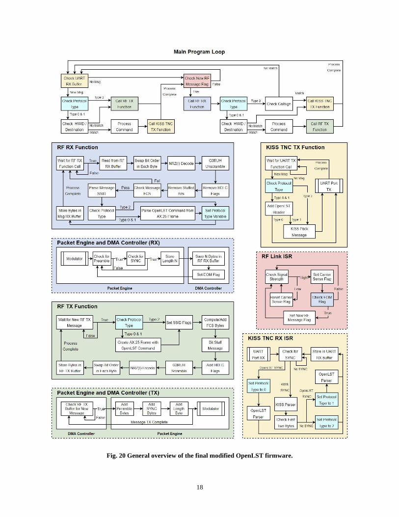
D. Modified OpenLST Firmware Logic
The overall modified OpenLST firmware structure and associated logic is shown in Fig. 20. Note how the main
program loop closely resembles the original main program shown in Fig. 12. The main difference lies in the additional
check for the protocol type identifier. This guarantees that command processing only occurs on OpenLST protocol
commands, thus maintaining the original network structure of the firmware. The block diagram also depicts the
functions available to the main program (included in solid-edged boxes) and the ISRs running in the background
(included in dashed-edged boxes). The different routines have been color coded to allow for better interpretation of
their overall role in the firmware. Processes associated with the KISS TNCs are shown in yellow, with the RF
transmission in green, with the RF reception in blue, and with the RF ISR in red. The global protocol type identifier
has been colored in cyan for reference.
18
Fig. 20 General overview of the final modified OpenLST firmware.

19
VII. Testing the Implementation
The proposed modifications were systematically tested prior to their final integration with the OpenLST firmware.
The testing process was divided into three phases, each intended to test a different aspect of the modifications. The
first phase focused on testing the encoding functions developed for AX.25 packet processing. The second phase aimed
at testing the modified host computer and OTA interfaces of the OpenLST. Lastly, the third phase looked at verifying
that the compatibility of the modified firmware with an AX.25 modem connected to third-party radios. This phased
testing approach was implemented to simplify the overall debugging process as the modifications progressed.
A. AX.25 Encoding Module Tests
A modular approach was taken when developing the encoders for the AX.25 packets. Dedicated functions were
created for each step of the encoding process. That is, isolated functions exist for bit stuffing, NRZ(I) encoding, and
G3RUH scrambling. This allowed for each encoder to be tested individually against various test cases. The encoding
result for each test sequence was computed by hand and compared with the function outputs. Tables 1-3 below depict
the sample packets used to test each encoder.
Table 1: NRZ(I) encoding test cases.
Case Decoded Encoded
B0 B1 B2 B3 B4 B5 B6 B7 B0 B1 B2 B3 B4 B5 B6 B7
1 0016 0016 0016 - - - - - 5516 5516 5516 - - - - -
2 7E16 7E16 7E16 - - - - - 7F16 7F16 7F16 - - - - -
3 FF16 FF16 FF16 - - - - - 0016 0016 0016 - - - - -
Table 2: Bit stuffing test cases.
Case Decoded Encoded
B0 B1 B2 B3 B4 B5 B6 B7 B0 B1 B2 B3 B4 B5 B6 B7
1 F016 A916 - - - - - - F016 5116 0116 - - - - -
2 FE16 0016 - - - - - - BE16 0116 0016 - - - - -
3 F816 0116 - - - - - - F816 0216 0016 - - - - -
4 FF16 FF16 FF16 FF16 FF16 - - - DF16 F716 7D16 DF16 F716 7D16 - -
5 FF16 FF16 FF16 FF16 FF16 FF16 - - DF16 F716 7D16 DF16 F716 7D16 DF16 0116
Table 3: G3RUH scrambling test case. Adapted from [11].
Case Decoded Encoded
B0 B1 B2 B3 B4 B5 B6 B7 B0 B1 B2 B3 B4 B5 B6 B7
1 7F16 7F16 7F16 7F16 D316 D416 3616 - 7F16 8F16 7616 0916 A916 5616 0E16 -
The test cases were applied in either direction. The byte sequences would be encoded, and the resulting output
would be used as an input for the decoding test case. If the original message was recovered, the test was considered a
success. The modular approach also facilitated the implementation of the encoders in the OpenLST firmware. Their
integration simply consisted of migrating the functions to the code and calling them at the appropriate points of the
reception/transmission process.
Functions were also created to compute the FCS of the AX.25 UI frames and to append/remove the header and
footer HDLC flags of each packet. A test case using a hypothetical AX.25 packet was developed to test these two
features, as well as to test the overall encoding and packing sequence. The tables that follow outline the expected

20
results for each step of the test case. Running through these tables in the opposite direction would correspond to the
unpacking test case. The sample packet used is outlined in Table 4 and contains the following parameters:
• Source Callsign: W4AQL (Georgia Tech’s Amateur Radio Club).
• Destination Callsign: GATECH.
• SSID: 016 for both.
• Payload: “Go Jackets!”
Table 4: Sample unpacked and decoded AX.25 UI frame.
N B0+N B1+N B2+N B3+N B4+N B5+N B6+N B7+N B8+N B9+N B10+N B11+N B12+N B13+N B14+N
0 8E16 8216 A816 8A16 8616 9016 6016 AE16 6816 8216 A216 9816 4016 6112 0316
15 F016 4716 6F16 2016 4A16 6116 6316 6B16 6516 7416 7316 2116 - - -
Note that the b5 and b6 bits of the last byte of a callsign will be set to 1 whenever the SSID nibble is not in use, as in
the case with this paper. Likewise, the last byte in the source address will have b0 set to 1 to indicate that no repeaters
were used during transmission. The packet shown in Table 5 includes the 16-bit FCS at the end of the frame. Note
that the MSB first and MSb first convention has already been accounted for.
Table 5: Sample AX.25 UI frame with computed FCS.
N B0+N B1+N B2+N B3+N B4+N B5+N B6+N B7+N B8+N B9+N B10+N B11+N B12+N B13+N B14+N
0 8E16 8216 A816 8A16 8616 9016 6016 AE16 6816 8216 A216 9816 4016 6112 0316
15 F016 4716 6F16 2016 4A16 6116 6316 6B16 6516 7416 7316 2116 A416 3116 -
Table 6 outlines the expected result after the bit stuffing of the message is performed. The HDLC header and footer
flags have also been added. Note that these are not bit stuffed. In the case of the OpenLST AX.25 implementation, 9
header flags and 2 footer flags are appended to each packet.
Table 6: Sample AX.25 UI frame after bit stuffing and adding header/footer HDLC flags.
N B0+N B1+N B2+N B3+N B4+N B5+N B6+N B7+N B8+N B9+N B10+N B11+N B12+N B13+N B14+N
0 7E16 7E16 7E16 7E16 7E16 7E16 7E16 7E16 7E16 8E16 8216 A816 8A16 8616 9016
15 6016 AE16 6816 8216 A216 9816 4016 6112 0316 F016 8D16 DE16 4016 9416 C216
30 C616 D616 CA16 E816 E616 4216 4816 6316 FC16 FC16 0016 - - - -
Tables 7 and 8 depict the expected results for the G3RUH scrambling and NRZ(I) encoding of the message. Note that
G3RUH scrambling occurs before the NRZ(I) encoding.
Table 7: Sample AX.25 UI frame after G3RUH scrambling.
N B0+N B1+N B2+N B3+N B4+N B5+N B6+N B7+N B8+N B9+N B10+N B11+N B12+N B13+N B14+N
0 7E16 9E16 6516 1B16 0316 7916 E816 0B16 1016 9916 3316 A316 DE16 2A16 8016
15 3716 D616 6416 6316 5D16 8816 7F16 8916 6B16 5A16 FC16 AF16 4716 B116 5916
30 3F16 9016 B716 B116 9216 0A16 C416 3616 1816 1216 1116 - - - -
21
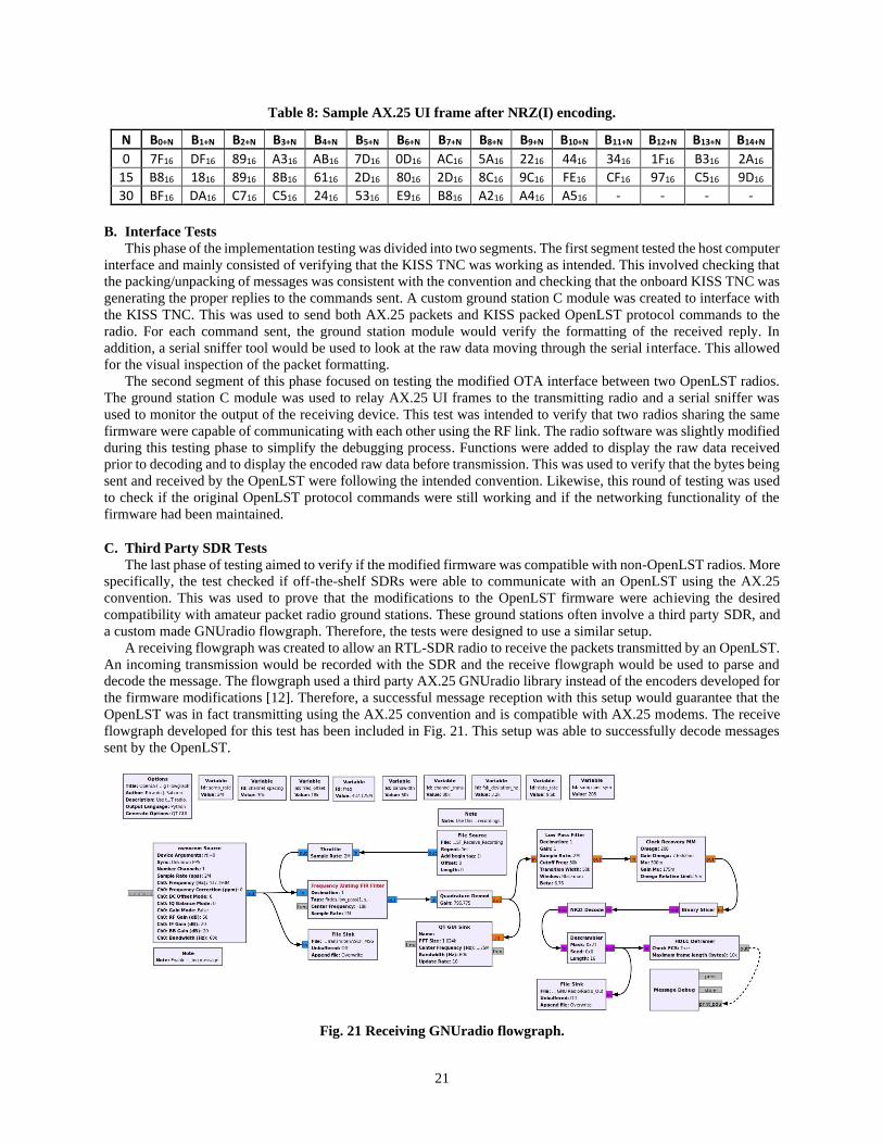
Table 8: Sample AX.25 UI frame after NRZ(I) encoding.
N B0+N B1+N B2+N B3+N B4+N B5+N B6+N B7+N B8+N B9+N B10+N B11+N B12+N B13+N B14+N
0 7F16 DF16 8916 A316 AB16 7D16 0D16 AC16 5A16 2216 4416 3416 1F16 B316 2A16
15 B816 1816 8916 8B16 6116 2D16 8016 2D16 8C16 9C16 FE16 CF16 9716 C516 9D16
30 BF16 DA16 C716 C516 2416 5316 E916 B816 A216 A416 A516 - - - -
B. Interface Tests
This phase of the implementation testing was divided into two segments. The first segment tested the host computer
interface and mainly consisted of verifying that the KISS TNC was working as intended. This involved checking that
the packing/unpacking of messages was consistent with the convention and checking that the onboard KISS TNC was
generating the proper replies to the commands sent. A custom ground station C module was created to interface with
the KISS TNC. This was used to send both AX.25 packets and KISS packed OpenLST protocol commands to the
radio. For each command sent, the ground station module would verify the formatting of the received reply. In
addition, a serial sniffer tool would be used to look at the raw data moving through the serial interface. This allowed
for the visual inspection of the packet formatting.
The second segment of this phase focused on testing the modified OTA interface between two OpenLST radios.
The ground station C module was used to relay AX.25 UI frames to the transmitting radio and a serial sniffer was
used to monitor the output of the receiving device. This test was intended to verify that two radios sharing the same
firmware were capable of communicating with each other using the RF link. The radio software was slightly modified
during this testing phase to simplify the debugging process. Functions were added to display the raw data received
prior to decoding and to display the encoded raw data before transmission. This was used to verify that the bytes being
sent and received by the OpenLST were following the intended convention. Likewise, this round of testing was used
to check if the original OpenLST protocol commands were still working and if the networking functionality of the
firmware had been maintained.
C. Third Party SDR Tests
The last phase of testing aimed to verify if the modified firmware was compatible with non-OpenLST radios. More
specifically, the test checked if off-the-shelf SDRs were able to communicate with an OpenLST using the AX.25
convention. This was used to prove that the modifications to the OpenLST firmware were achieving the desired
compatibility with amateur packet radio ground stations. These ground stations often involve a third party SDR, and
a custom made GNUradio flowgraph. Therefore, the tests were designed to use a similar setup.
A receiving flowgraph was created to allow an RTL-SDR radio to receive the packets transmitted by an OpenLST.
An incoming transmission would be recorded with the SDR and the receive flowgraph would be used to parse and
decode the message. The flowgraph used a third party AX.25 GNUradio library instead of the encoders developed for
the firmware modifications [12]. Therefore, a successful message reception with this setup would guarantee that the
OpenLST was in fact transmitting using the AX.25 convention and is compatible with AX.25 modems. The receive
flowgraph developed for this test has been included in Fig. 21. This setup was able to successfully decode messages
sent by the OpenLST.
Fig. 21 Receiving GNUradio flowgraph.
22
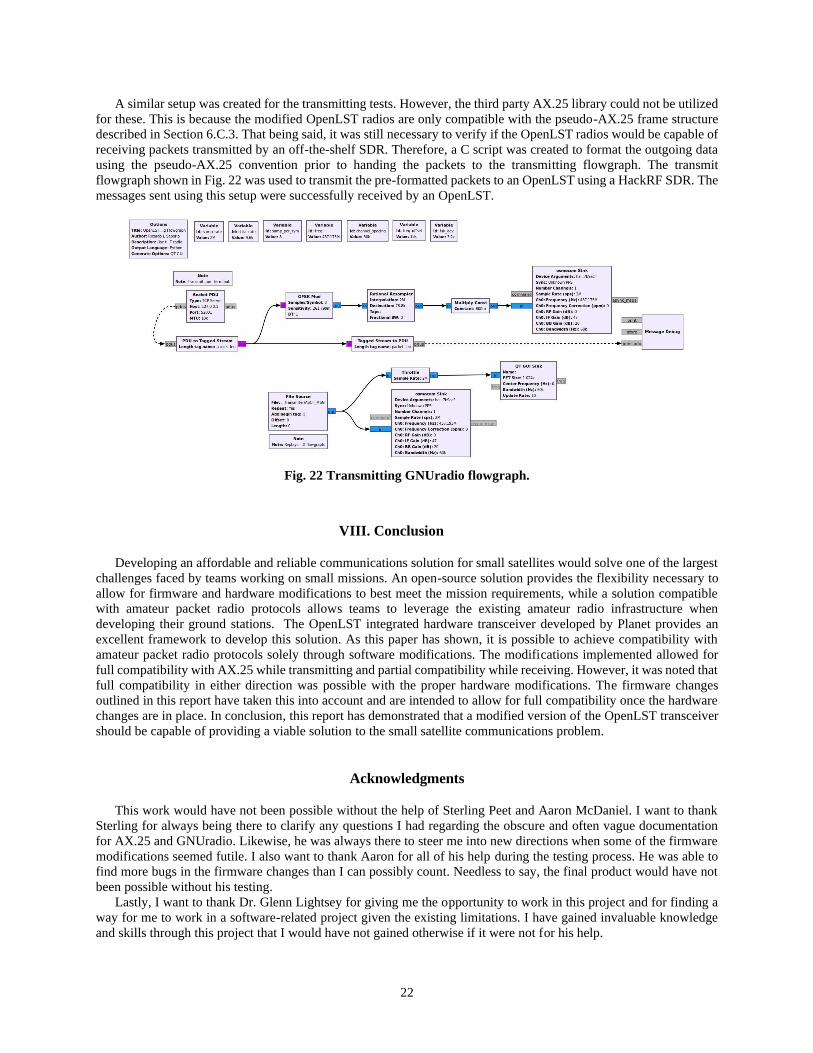
A similar setup was created for the transmitting tests. However, the third party AX.25 library could not be utilized
for these. This is because the modified OpenLST radios are only compatible with the pseudo-AX.25 frame structure
described in Section 6.C.3. That being said, it was still necessary to verify if the OpenLST radios would be capable of
receiving packets transmitted by an off-the-shelf SDR. Therefore, a C script was created to format the outgoing data
using the pseudo-AX.25 convention prior to handing the packets to the transmitting flowgraph. The transmit
flowgraph shown in Fig. 22 was used to transmit the pre-formatted packets to an OpenLST using a HackRF SDR. The
messages sent using this setup were successfully received by an OpenLST.
Fig. 22 Transmitting GNUradio flowgraph.
VIII. Conclusion
Developing an affordable and reliable communications solution for small satellites would solve one of the largest
challenges faced by teams working on small missions. An open-source solution provides the flexibility necessary to
allow for firmware and hardware modifications to best meet the mission requirements, while a solution compatible
with amateur packet radio protocols allows teams to leverage the existing amateur radio infrastructure when
developing their ground stations. The OpenLST integrated hardware transceiver developed by Planet provides an
excellent framework to develop this solution. As this paper has shown, it is possible to achieve compatibility with
amateur packet radio protocols solely through software modifications. The modifications implemented allowed for
full compatibility with AX.25 while transmitting and partial compatibility while receiving. However, it was noted that
full compatibility in either direction was possible with the proper hardware modifications. The firmware changes
outlined in this report have taken this into account and are intended to allow for full compatibility once the hardware
changes are in place. In conclusion, this report has demonstrated that a modified version of the OpenLST transceiver
should be capable of providing a viable solution to the small satellite communications problem.
Acknowledgments
This work would have not been possible without the help of Sterling Peet and Aaron McDaniel. I want to thank
Sterling for always being there to clarify any questions I had regarding the obscure and often vague documentation
for AX.25 and GNUradio. Likewise, he was always there to steer me into new directions when some of the firmware
modifications seemed futile. I also want to thank Aaron for all of his help during the testing process. He was able to
find more bugs in the firmware changes than I can possibly count. Needless to say, the final product would have not
been possible without his testing.
Lastly, I want to thank Dr. Glenn Lightsey for giving me the opportunity to work in this project and for finding a
way for me to work in a software-related project given the existing limitations. I have gained invaluable knowledge
and skills through this project that I would have not gained otherwise if it were not for his help.
23
References
[1] “Planet Releases OpenLST, An Open Radio Solution,” Planet. Aug. 2018. Available:
https://www.planet.com/pulse/planet-openlst-radio-solution-for-cubesats/
[2] “History of IARU,” IARU. Jan. 2020. Available:
https://www.iaru.org/about-us/organisation-and-history/history-of-iaru/
[3] Information technology – Open Systems Interconnection – Basic Reference Model: The Basic Model. ISO/IEC 7498-1:
1994(E), 1994.
[4] Low-Power SoC (System-on-Chip) with MCU, Memory, Sub1 GHz RF Transceiver, and USB Controller. CC1110-CC1111.
Rev. H. Texas Instruments. Jul. 2013.
[5] Information technology – Telecommunications and information exchange between systems – High-level data link control
(HDLC) procedures. ISO/IEC 13239:2002, 2002.
[6] Beech, W. A., Nielsen, D. E., and Taylor, J., “AX.25 Link Access Protocol for Amateur Packet Radio,” Tucson Amateur Packet
Radio Corporation, Jul. 1998.
[7] Miller, G., “9600 Baud Packet Radio Modem Design.” Apr. 1995. Available:
https://www.amsat.org/amsat/articles/g3ruh/109.html
[8] Chepponis, M., and Karn, P., “The KISS TNC: A simple Host-to-TNC communications protocol.” Jan. 1997. Available:
http://www.ax25.net/kiss.aspx
[9] Finnegan, K. W., “Examining Ambiguities in the Automatic Packet Reporting System,” Master Thesis, California Polytechnic
State University, San Luis Obispo, CA, 2014.
[10] “Mueller and Muller Timing Synchronization Algorithm,” Wireless Pi. Jan. 2020. Available:
https://wirelesspi.com/mueller-and-muller-timing-synchronization-algorithm/
[11] Grønstad, M. A., “Implementation of a Communication Protocol for CubeSTAR,” Master Thesis, University of Oslo, Jul 2010.
[12] Estévez, D., “gr-satellites documentation.” Jan. 2020. Available: https://gr-satellites.readthedocs.io/en/latest/