development of antimicrobial thin-film composite forward ...€¦ · adel soroush a thesis in the...
TRANSCRIPT

Development of Antimicrobial Thin-Film Composite Forward Osmosis Membranes by
Using Silver Nanoparticles and Graphene Oxide Nanosheets
Adel Soroush
A Thesis
In
The Department of
Building, Civil and Environmental Engineering
Presented in partial fulfillment of the requirement
For the Degree of Master of Applied Science (Civil Engineering) at
Concordia University
Montreal, Quebec, Canada.
September 2015
© Adel Soroush, 2015

CONCORDIA UNIVERSITY
School of Graduate Studies
This is to certify that the thesis prepared
By: Adel Soroush
Entitled: Conductive Ultrafiltration Membrane Fabrication via a Novel Vacuum-Assisted
Layer-by-Layer Assembly of Functionalized Carbon Nanotubes
and submitted in partial fulfillment of the requirements for the degree of
Master of Applied Science (Civil Engineering)
complies with the regulations of the University and meets the accepted standards with respect to
originality and quality.
Signed by the final Examining Committee:
Chair
Dr. Catherine Mulligan
Examiner
Dr. Fuzhan Nasiri
Examiner
Dr. Ali Dolatabadi
Supervisor
Dr. Saifur Rahaman
Approved by
Dr. Fariborz Haghighat
2015 Dr. Amir Asif
iii
Abstract
Development of Antimicrobial Thin-Film Composite Forward Osmosis
Membranes by Using Silver Nanoparticles and Graphene Oxide
Nanosheets
Adel Soroush
Membrane filtration has been gaining great attention in water and wastewater treatments
processes because of its high-performance efficacy, modular design, and smaller physical
footprint. Thanks to special membrane materials and structure, osmosis processes are widely
used in water desalination and water reuse processes. Aside from their high performance of
osmosis processes, they inevitably do suffer from membrane fouling and biofouling during
treatment processes that significantly decrease water treatment performance and final product
quality.
Two different biocidal nanomaterials and their combinations were used in this project for
the modification of membrane surfaces and the development of biocidal membranes: silver
nanoparticles (AgNPs) and graphene oxide nanosheets (GO).
GO/Ag nanocomposite functionalization of TFC FO membranes provides an efficient
antimicrobial surface that has more desirable characteristics than those with only GO or Ag NPs.
Also, the higher hydrophilicity of the resulting membranes, the low material cost, and the ease of
preparation (dip coating method) offer a more efficient approach than other modification
methods. In comparison to the formation of AgNPs on pristine TFC FO membranes, the in situ
formation of AgNPs on the GO-modified membrane surface resulted in greater silver loading,
higher and longer lasting ion-release, and more effective antimicrobial properties.
The regeneration of GO-Ag-modified membranes was also examined. Modified
membranes were kept in DI water for seven days to emulate depletion. AgNPs were successfully
formed using an in-situ procedure on the surface of the membranes, identical to the initial
membrane formation. Results show that membrane hydrophilicity and its antimicrobial ability
decreased after the releasing process, however, the regeneration process allowed the membrane

iv
to nearly regain the properties seen in the freshly modified membrane. The simple regeneration
method developed in this study will allow on-site modification and regeneration of different
types of industrial membrane modules (hollow fiber, spiral wound).

v
Acknowledgments
I would like to acknowledge and extend my heartfelt gratitude to my supervisor, Dr.
Saifur Rahaman, for granting me an opportunity to pursue my graduate studies at Concordia
University, as well as for his continuous inspiration and guidance in this research. I really
appreciate his vast arena of knowledge, his expertise and his patience during correcting my
writing. His encouraging words always cheered me up in difficult times of problem solving.

vi
Dedication
To my lovely parents for their love and support.

vii
Table of Contents
Table of Contents .......................................................................................................................... vii
List of Figures ................................................................................................................................. x
List of Tables ................................................................................................................................ xii
List of Abbreviations ................................................................................................................... xiii
1 INTRODUCTION .................................................................................................................. 1
1.1 Motivation ........................................................................................................................ 1
1.1.1 Water Scarcity throughout the World ....................................................................... 1
1.2 Osmosis-Based Membrane Processes for Water Desalination and Reuse ....................... 2
1.3 Fouling and Biofouling Mitigation through Surface Modification .................................. 7
1.4 Biocidal Nanomaterials .................................................................................................... 7
1.4.1 Silver Nanoparticles .................................................................................................. 7
1.4.2 Graphene Oxide Nanosheets ................................................................................... 13
1.5 Objective ........................................................................................................................ 19
1.6 Organization of Dissertation .......................................................................................... 19
2 SURFACE MODIFICATION OF THIN FILM COMPOSITE FORWARD OSMOSIS
MEMBRANE BY SILVER-DECORATED GRAPHENE-OXIDE NANOSHEETS ................. 20
2.1 Introduction .................................................................................................................... 20
2.2 Materials and Methods ................................................................................................... 22
2.2.1 Materials ................................................................................................................. 22
2.2.2 Synthesis and Characterization of AgNPs and GO/Ag Nanocomposites ............... 22
2.2.3 Surface Modification and Characterization of TFC FO Membranes ...................... 23
2.2.4 Antimicrobial Activity of GO/Ag Functionalized Membranes .............................. 26
2.2.5 Silver Release Experiments .................................................................................... 27

viii
2.3 Results and Discussion ................................................................................................... 27
2.3.1 Successful Graphene Oxide/ Silver Nanocomposite Synthesis Confirmed by UV-
Vis, TEM, TGA and XRD Analyses .................................................................................... 27
2.3.2 Graphene Oxide/ Silver Nanocomposites were Covalently Bonded to the Surface of
the TFC Polyamide Membrane ............................................................................................. 28
2.3.3 Membrane Transport Properties were not Significantly Affected by GO/Ag
Functionalization................................................................................................................... 31
2.3.4 The Functionalized Membrane Exhibited Strong Antimicrobial Activity ............. 33
2.3.5 Silver Ion Release Behavior was Different for Composite and only AgNP Modified
Membranes ............................................................................................................................ 36
2.4 Conclusions .................................................................................................................... 36
2.5 Supporting Information .................................................................................................. 38
2.5.1 Materials and Methods ............................................................................................ 38
2.5.2 Nanoparticles and Nanocomposites Characterization ............................................ 39
3 IN SITU SILVER DECORATION ON GRAPHENE OXIDE-TREATED THIN FILM
COMPOSITE FORWARD OSMOSIS MEMBRANES: BIOCIDAL PROPERTIES AND
REGENERATION POTENTIAL ................................................................................................. 47
3.1 Introduction .................................................................................................................... 47
3.2 EXPERIMENTAL ......................................................................................................... 48
3.2.1 Materials ................................................................................................................. 48
3.2.2 Surface modification with GO nanosheets ............................................................. 48
3.2.3 In situ Ag NP formation on GO modified membranes ........................................... 49
3.2.4 Membrane characterization ..................................................................................... 49
3.2.5 Anti-microbial properties of modified membranes ................................................. 50
3.2.6 Loading, stability and release of Ag NPs ................................................................ 50
3.2.7 Regeneration of Ag NPs on the membrane surfaces .............................................. 50

ix
3.3 Results and Discussion ................................................................................................... 51
3.3.1 Ag NPs were formed successfully and their loading increased in the presence of
GO nanosheets ...................................................................................................................... 51
3.3.2 Membrane surface hydrophilicity changed after modification while performance
remained unchanged ............................................................................................................. 53
3.3.3 Bacterial growth inhibition increased in the presence of GO nanosheets .............. 56
3.3.4 Ag NP regenerated successfully on the surface of GO-Ag-modified membranes . 58
3.4 Conclusion ...................................................................................................................... 60
3.5 Supporting Information .................................................................................................. 60
3.5.1 TFC membrane modification .................................................................................. 60
3.5.2 Scanning Electron Microscopy ............................................................................... 61
3.5.3 Contact Angle Measurements ................................................................................. 61
3.5.4 Membrane Performance Evaluation ....................................................................... 62
3.5.5 Antimicrobial Evaluation of Membranes ................................................................ 63
4 CONCLUSION and RECOMMENDATIONS .................................................................... 70
5 REFERENCES ..................................................................................................................... 72

x
List of Figures
Figure 1: The schematic picture of pore size range for different pressure-driven membranes ...... 3
Figure 2: Schematic picture of the reverse osmosis process used for seawater desalination ......... 5
Figure 3: Schematic picture of FO and PRO systems for water treatment ..................................... 6
Figure 4: Schematic illustration of the 4-step silver formation mechanism ................................... 8
Figure 5: Diagram summarizing nanoscaled silver interaction with bacterial cells ....................... 9
Figure 6: Chemical and 3D structures of GO nanosheets. ............................................................ 15
Figure 7: Mechanisms of cellular inactivation of graphene nanomaterials with bacteria ............ 16
Figure 8: Surface functionalization of membranes with graphene nanomaterials ........................ 18
Figure 9: covalently bonded AgNP-decorated GO nanosheets through click chemistry ............. 26
Figure 10: Characterization of the GO/Ag nanocomposite .......................................................... 30
Figure 11: FESEM images of pristine and functionalized TFC membranes ................................ 30
Figure 12: Surface characterization of pristine and functionalized TFC FO membranes ............ 33
Figure 13: Membrane properties before and after modification. .................................................. 35
Figure 14: Colony-forming units (CFU) after E. coli cells had been in contact with the control
and GO/Ag functionalized membranes for 1 h at room temperature ............................................ 37
Figure 15: FE-SEM images and backscatter electron imaging for functionalized membranes .... 39
Figure 16: TEM images of (A) GO, (B) Ag NPs, (C) GO/Ag nanocomposite ............................ 41
Figure 17: ATR-FTIR spectra of (A) GO nanosheets and GO/Ag nanocomposite, and (B)
ControlTFC and GO/Ag nanocomposite functionalized TFC membranes. .................................. 42
Figure 18: Zeta potential of the surface of the pristine and functionalized membranes ............... 43
Figure 19: XPS results for pristine membrane and cysteamine treated TFC FO membranes. ... 44
Figure 20: XPS results showing physical stability of silver NPs.................................................. 46
Figure 21: In situ Ag NP formation on the surface of GO-modified membranes ........................ 49
Figure 22: BSE-SEM and AFM images of pristine and functionalized membranes .................... 53
Figure 23: XPS spectra of pristine (A) and modified membranes (B). ICP-MS results of loading
and stability (C) as well as releasing behavior (D) of functionalized membranes ....................... 54
Figure 24: Water contact angle and surface energy, drop shape and performance of pristine and
modified membranes ..................................................................................................................... 55
Figure 25: The number of live cells on the pristine, Ag, GO and GO-Ag-modified surfaces over 1
hr contact with E. coli D21f2 bacterial suspension ....................................................................... 57

xi
Figure 26: Normalized silver content on the surface of membranes (A), antimicrobial properties
of pristine and modified membranes (B), and XPS spectra for Ag (3d) (C), Raman shift of
pristine and modified membranes (D) before and after regeneration. .......................................... 59
Figure 27: Images of pristine, TFC-GO, TFC-Ag and TFC-GO-Ag-modified membranes. ....... 64
Figure 28: FE-SEM images of pristine and modified membranes ............................................... 65
Figure 29: Physical stability of Ag NPs on the surface of modified membranes after 7 minutes of
bath sonication .............................................................................................................................. 66
Figure 30: XPS peak analysis for TFC and modified membranes before and after regeneration 67
Figure 31: SEM images of cells (E. coli D21f2) after contacting with pristine and modified
membranes for 1 h ........................................................................................................................ 68

xii
List of Tables
Table 1: Surface roughness properties of the pristine and the GO/Ag functionalized TFC FO
membranes .................................................................................................................................... 43
Table 2: Elemental composition by XPS analysis of the membrane surface of pristine and
functionalized membranes, before and after sonication. .............................................................. 45
Table 3: Surface roughness properties of the pristine and functionalized TFC FO membranes. . 69

xiii
List of Abbreviations
WHO World Health Organization
UNICEF United Nations Children's Emergency Fund
RO Reverse Osmosis
MF Microfiltration
UF Ultrafiltration
NF Nanofiltration
ED Electrodialysis
FO Forward Osmosis
PRO Pressure Retarded Osmosis
TFC Thin Film Composite
CTA Cellulose Triacetate
Ag Silver
NPs Nanoparticles
GO Graphene Oxide
PVP Polyvinylpyrrolidone
ATP Adenosine Triphosphate
DNA Deoxyribonucleic acid
ROS Reactive Oxygen Species
PEI Polyethyleneimine
EDC N-Ethyl-N′-(3-dimethylaminopropyl)

xiv
carbodiimide
NHS N-Hydroxysuccinimide
ED Ethylenediamine
PES Polyethersulfone
PSf Polysulfone
LBL Layer-by-layer
PDMS Polydimethylsiloxane
EPS extracellular polymeric substances
PDA Polydopamine
TGA Thermal Gravimetric Analysis
FE-SEM Field Emission scanning Electron Microscopy
AFM Atomic Force Microscopy
HR-TEM High Resolution Transmission Electron
Microscopy
EKA Electrokinetic Analyzer
XRD X-ray Diffraction
XPS X-ray Photoelectron Spectroscopy
ATR-FTIR Attenuated total reflection-Fourier transform
infrared spectroscopy
BSE Back-scattering Electron
ICP-MS Inductively Coupled Plasma Mass
Spectroscopy

xv
BSA Bovine Serum Albomine
DI water Di-ionized water

1
1 INTRODUCTION
1.1 Motivation
Global demand for clean water is growing in parallel with population growth; in coming
years, water will present itself as a pivotal environmental issue. Worldwide attention is focusing
on the complimentary technologies of water supply, reuse, and purification. Membrane
processes, among other energy-efficient technologies, enjoy excellent reputations due to their
modular design, ease of preparation, and high efficacy. Unfortunately, usage of these
technologies entail some inherent shortcomings, mostly attributed to membrane fouling and
biofouling. Through this study, we propose novel methods to overcome the problems as
mentioned above.
1.1.1 Water Scarcity throughout the World
Water is the core of sustainable development. Water resources, and the wide range of
services they are involved in support poverty reduction, economic growth, and environmental
sustainability. Water plays a significant role in the social well-being and economic livelihoods of
billions1 notably in terms of areas ranging from food and energy security to human and
environmental health. According to the joint monitory report of the World Health Organization
(WHO) and the United Nations Children's Fund (UNICEF), although 1.6 billion people are using
a higher quality of pipelines and safe water, 748 million do not use an improved water source,
and 2.5 billion do not use improved sanitation facilities2, 3
. Nowadays, one-third of the world’s
population is living in water-stressed countries, and by 2025 this number is predicted to increase
to nearly two-thirds4. Several measures have been implemented to alleviate stresses on water
supplies, such as water preservation, infrastructure repair and improvement of water distribution
and irrigation systems.
While these measures are necessary and crucial, they only preserve existing water
resources and do nothing to expand them. The only available methods for increasing our water
supply are water desalination and water reuse processes5. Of these, water desalination shows
much promise as it offers high quality and stable, fresh water, and can be scaled for different
regions of the world with varying capacities. Water desalination technologies are categorized
into two important spheres: thermal processes and membrane-based processes. Early-stage
implementation of large-scale thermal water desalination plants has occurred in the arid Persian

2
Gulf nations. These processes involve heating and evaporating seawater; the steam is then
condensed to produce distilled fresh water. While technically capable of producing water, these
facilities consume substantial amounts of energy and emit huge volumes of greenhouse gasses.
Membrane based processes offer some of the most energy-efficient technologies for
seawater desalination. Reverse osmosis (RO) is one such process, where seawater is pressurized
against semi-permeable membranes to separate water molecules (which can pass) from salts
(which are rejected). RO is the most efficient membrane based desalination method, and is the
current benchmark for comparison with any new desalination technologies.
1.2 Osmosis-Based Membrane Processes for Water Desalination and Reuse
There are four established pressure-driven industrial membrane processes: microfiltration (MF),
ultrafiltration (UF), reverse osmosis (RO), and electrodialysis (ED)6. The membranes for each of
these processes require different structures and pore sizes. While MF and UF membranes consist
of mostly asymmetric porous layers, RO membranes are composed of multi-layers: a dense,
active polyamide top layer, an asymmetric, porous polysulfone middle layer and a polyester non-
woven bottom layer. Based on pore size and structure, membranes are capable of separating
different substances and contaminants from water. The membrane structure and applications are
depicted in Figure. 1.

3
Figure 1: A schematic comparison of pore size range for different pressure-driven membranes and the
different types of contaminants that can be separated by each membrane process6.
RO is used mainly in water desalination and currently occupies 50% of the desalination
market. Desalination aims to increase the overall supply of fresh water via desalination of
seawater and saline aquifers that comprise 97.5% of all water on the Earth. Therefore, filtration
of a tiny portion could have a significant impact on water supplies and mitigate future shortages.
Although desalination technologies in all forms are often considered to be capital- and energy-
intensive processes, RO consumes less energy and is impacted less from corrosion and scaling
than thermal desalination processes7, 8
.
Reverse osmosis uses membranes that are permeable to water but essentially
impermeable to salt. Pressurized salt-containing water contacts the feed side of the membrane
and purified water is withdrawn as a low-pressure permeate. The separation mechanism
occurring in RO systems is solution-diffusion; where water molecules are dissolved in the
polyamide active layer of the membrane, and then diffuse through the porous middle layer. The
water flux Ji is a function of the applied pressure and concentration gradients across the
membrane:

4
𝐽𝑖 = 𝐴(∆𝑝 − ∆𝜋) (1-1)
where ∆𝑝 is the pressure difference across the membrane, ∆𝜋 is the osmotic pressure difference
across the membrane, and A is constant.
The salt flux Jj across the RO membrane is described as:
𝐽𝑗 = 𝐵(𝐶𝑗0 − 𝐶𝐽𝑙) (1-2)
where B is the salt permeability constant and Cj0 and Cjl, respectively, are the salt concentration
on the feed and permeate sides of the membrane. Selectivity can be calculated in different ways,
but conventionally it is measured as the salt rejection coefficient R as:
𝑅 = [1 −𝐶𝑗𝑙
𝐶𝑗0] × 100% (1-3)
Although RO systems (Figure 2) have a relatively low rate of energy consumption, they do
require the use of high-cost electrical energy and still are impacted by fouling and biofouling
problems. A portion of the electrical energy usage is inevitable due to the reversible
thermodynamic process, which is independent of the system and mechanisms. However, through
the implementation of novel, robust, high flux, low fouling membranes, energy usage can be
significantly reduced.

5
Figure 2: Schematic picture of the reverse osmosis process used for seawater desalination5.
Other emerging osmosis-based desalination/separation processes include forward
osmosis (FO) and pressure-retarded osmosis (PRO) where a semi-permeable membrane is placed
between two solutions of different concentrations: a highly concentrated saline draw solution and
a more dilute feed solution. The osmotic pressure difference between the two solutions drives
water flow from feed to draw side. FO can address several drawbacks of RO and other pressure-
driven membrane processes.

6
Figure 3: Schematic picture of FO and PRO systems for water treatment
Despite recent developments in FO, there are still challenges that need to be overcome
before it can be successfully implemented. There is still some confusion about the energy
consumed during the FO process9. The ideal draw solution has remained elusive and is
considered to be the “Holy Grail” in FO. To be considered optimal, the draw solution needs to be
inexpensive, stable, non-toxic, highly soluble and mobile, have a molecular size large enough to
limit reverse salt flux though the FO membrane’s active layer, and be able to mitigate internal
concentration polarization (ICP)10, 11
. Fouling and biofouling of FO membranes are also a major
challenges. Fouling is the deposition and adsorption of feed water constituents to the membrane
surface. Such constituents include organic and inorganic compounds, colloidal particles, and
microorganisms. Fouling deteriorates the membrane performance and decreases the membrane
lifespan, which in turn increases operating costs for desalination. Although FO membranes are
considered to have lower fouling propensities than RO membranes because of their loosely
packed layers, the membrane surface is intrinsically prone to fouling and biofouling, and
therefore requires some modifications to counteract this problem.
FO
Mode
PRO
Mode

7
1.3 Fouling and Biofouling Mitigation through Surface Modification
Fouling propensity in FO is governed by hydrodynamic operating conditions and the
affinity of foulants to the membrane surface. Therefore, fouling resistant membranes are
characterized by biocidal, hydrophilic, inert surfaces, and smooth topographies that prevent
foulant attachment. There are two different categories of membranes used in FO systems:
asymmetric cellulose triacetate (CTA) and polyamide thin-film composite (PA TFC)
membranes. The majority of studies on fouling in FO processes are related to CTA membranes
due to CTA being the primary type of membranes available in the commercial market until
recently12-17
. However, state-of-the-art TFC membranes have been shown to have higher water
permeability and salt rejection. They are increasingly being studied because they are inherently
prone to fouling due to their rough surfaces and the presence of different types of functional
groups on the surface such as carboxylic groups4.
Various methods of surface property modifications18
have been employed for fouling and
biofouling mitigation; the addition of different types of functional groups12
, polymer brushes19
,
modified nanoparticles,20
and other biocidal materials21
. Surface modifications aim to increase
the membrane’s hydrophilicity, smoothness, and biocidal properties. The use of nanomaterials in
surface modifications has recently attracted great attention because of the special properties
nanomaterials can provide to a large surface area and biocidal properties they can add. Due to
their significant biocidal and hydrophilic properties, silver nanoparticles (Ag NPs) and graphene
oxide nanosheets (GO) have gained focal attention.
1.4 Biocidal Nanomaterials
1.4.1 Silver Nanoparticles
Metallic nanoparticles are of particular interest due to their unique properties and a myriad of
promising applications in areas such as environmental science and engineering22
. Due to its
broad spectrum of antimicrobial properties, silver is widely used in biomedical applications,
water and air purification, cosmetics, clothing, and other household products. With the advent of
nanotechnology, the applications of silver have been expanded, and it is now the engineering
nanomaterial most commonly used in consumer products23
. Ag NPs are nanoscale clusters of
metallic silver atoms, Ag0, engineered for a specific practical purpose: typically antimicrobial
and sterile applications.

8
The intrinsic properties of metal nanostructures can be designed and tailored by controlling their
size, shape, composition, crystallinity, and structure (e.g. solid versus hollow)24, 25
. The most
common method of producing of Ag NPs is through the chemical reduction of a silver salt (the
precursor to silver) by dissolving it in water with a reducing agent such as sodium borohydride
(NaBH4), citrate, glucose, hydrazine, or ascorbate26
. Strong reductants such as NaBH4 lead to
small monodisperse particles, which are easier to control than larger particles. Weaker reductants
generate large polydisperse particles through slower reactions. To produce Ag NPs with
controlled size, a two-step method is utilized. In the first step, smaller nuclei particles are
prepared by employing a strong reducing agent. In the second step, they are enlarged by a weak
reducing agent27
. Another effective method for controlling the size and shape of Ag NPs is using
polymeric capping agents such as poly vinylpyrrolidone (PVP). Ag NP size, shape and stability
can be simply controlled by tuning the ratio between the capping agent (PVP) and precursor salt
(AgNO3)28
. This ratio can also be used to optimize the thickness of the PVP layer and the
location of PVP chains on the surface of seed particles. Finally, this optimization can alter the
resistance of each crystal face to growth (addition of silver atoms) and can also lead to the
formation of silver nanostructures with distinct shapes and sizes.
Figure 4: Schematic illustration of the 4-step silver formation mechanism29.
As depicted in Figure 4, silver nitrate is first reduced by NaBH4 (1) followed by rapid
growth due to coalescence (2). After these initial steps, the mean radius of silver is
approximately 1 nm. After reaching the metastable phase (3), the electrostatic stability of the
particles decreases due to the hydrolysis of borohydride, which leads to a second coalescence
step (4) and stable particle formation (5). At the fifth step, the size of Ag NPs increases to about
7 nm29, 30
.

9
The reduction of silver nitrate by sodium borohydride is governed by the following equation:
AgNO3 + NaBH4 → Ag + 1
2 𝐻2 +
1
2 𝐵2𝐻6 + 𝑁𝑎𝑁𝑂3
Sodium borohydride also reacts with water relatively slowly31
:
𝑁𝑎𝐵𝐻4 + 2𝐻2𝑂 → 𝑁𝑎𝐵𝑂2 + 4𝐻2
Although the mechanism of bacterial inactivation by Ag NPs is not fully elucidated, the
three most common mechanisms of toxicity proposed are(1) release silver ions and generate
ROS; (2) interact with membrane proteins affecting their correct function; (3) accumulate in the
cell membrane affecting membrane permeability; and (4) enter into the cell where it can generate
ROS, release silver ions, and affect DNA Some of the observed and hypothesized interactions
between Ag NPs and bacterial cells are illustrated in Figure 5.
Figure 5: Diagram summarizing nanoscaled silver interaction with bacterial cells. Nanoscaled silver may
(1) release silver ions and generate ROS; (2) interact with membrane proteins affecting their correct
function; (3) accumulate in the cell membrane affecting membrane permeability; and (4) enter into the
cell where it can generate ROS, release silver ions, and affect DNA. Generated ROS may also affect
DNA, cell membrane, and membrane proteins, and silver ion release will likely affect DNA and
membrane proteins23.
(1)
(2)
(4)
(3)

10
Ag NP toxicity is influenced by several factors such as particle size, shape, crystallinity,
surface chemistry, and capping agents, as well as other environmental factors such as pH, ionic
strength, and the presence of ligands, divalent cations, and macromolecules. As particle size
decreases, the specific surface area increases thus exposing a higher number of atoms on the
surface to redox and biochemical reactions. Furthermore, one of the key mechanisms of bacterial
inactivation is the release of silver ions. In general, the rate of release is proportional to the
particle surface area; smaller particles release more rapidly than larger particles and macroscopic
materials32, 33
. Atom densities at [1 1 1] facet also increase the toxicity of Ag NPs. Therefore, Ag
NP shape has an important effect on its toxicity34
. Truncated triangular NPs exert stronger
antibacterial activity than spherical and rod-shaped Ag NPs because they have more [1 1 1]
facets and can be more reactive35
. The stability of Ag NPs also influences biocidal activity since
aggregation of NPs cause a decrease of biocidal activity36
. Different types of surfactants and
polymers (e.g. sodium dodecyl sulfate and PVP) are used to make NPs stable and enhance
biocidal activity. However, some ligand-capped Ag NPs are less bioactive because the capping
agent hinders the release of silver37
.
Environmental conditions such as pH, ionic strength, the presence of complexing agents
and natural organic matter, as well as NPs properties affect the toxicity of Ag NPs. They affect
the aggregation of Ag NPs by either screening electrical double layer repulsion38
or ion-release
that is governed by aquatic media pH, redox potential, ionic composition, and exposure to light34
.
The applications of Ag NPs in membrane science have been widely studied. Used in both
surface modification and bulk incorporation, Ag NPs increase the biocidal activity of membranes
for mitigation of biofouling. Zodrow et al39
incorporated Ag NPs in polysulfone (PSf)
membranes to study antimicrobial properties and bacterial attachment to the membrane surface.
They concluded that the modified membranes, specifically the Ag+ ions, were effective against
two strains of bacteria. An adverse issue observed in the use of this method was a rapid depletion
of silver due to dissolution. The researchers proposed encapsulating silver for a controlled
release and then regenerating the silver after depletion. Mauter et al40
encapsulated antimicrobial
Ag NPs in positively charged polyethyleneimine (PEI) and covalently bonded it to plasma-
modified PSf ultrafiltration membranes in the presence, and absence of 1-ethyl-3-(3-
dimethylaminopropyl) carbodiimide hydrochloride (EDC). They concluded that this new method
11
of antimicrobial Ag NP surface modification increased the durability and biocidal properties of
the final reactive nanocomposite membranes. The results showed that the concentration of
released silver decreased by more than ten times after only two days. They concluded that using
EDC to fix the Ag NPs in place aided the biocidal properties of the membranes significantly.
They also proposed Ag NP regeneration for increased long-term effectiveness of nanocomposite
membranes.
A problem with surface modification of PSf membranes lies in the difficult and non-
permanent functionalization of the surface through plasma treatment. Sawada et al41
developed
hydrophilic polyethersulfone (PES) hollow fiber membranes through photo-polymerization of an
acrylamide layer and formation of Ag NPs by chemical reduction. Both organic and biofouling
were investigated, and they concluded that the acrylamide grafting layer was effective for
improving the membrane hydrophilicity. They improved organic antifouling properties with a
bovine serum albumin (BSA) solution. Finally, antimicrobial properties of Ag NP membranes
were confirmed through the halo zone test and the shake flask method. Although both organic
antifouling and antimicrobial properties were achieved, the modification process was difficult
and complicated.
Kim et al42
developed nanosilver and multi-walled carbon nanotube (MWNTs) thin-film
nanocomposite (TFN) membranes. The TFN membrane was synthesized by the interfacial
polymerization of a support layer containing acid-modified MWNTs and a thin-film layer of Ag
NPs. They concluded that incorporation of MWNTs and Ag NPs increased both the water
permeability of the membranes and their hydrophilicity. Salt rejection remained unchanged, and
the modified membranes showed enhanced anti-biofouling properties. However, the study was
limited by the fast release of silver ions and the lack of a regeneration process. Furthermore, Ag
NPs were distributed within the polyamide layer, and their efficacy in preventing cell-attachment
was controversial. The antimicrobial properties of the membranes were examined through the
disk diffusion method that is more of a qualitative as opposed to a quantitative test.
Liu et al43
synthesized novel antibacterial silver nanocomposite nanofiltration (NF) and
forward osmosis membranes using layer-by-layer assembly. They prepared a polyacrylonitrile
porous layer and incorporated Ag NPs through dispersion in a polyelectrolyte solution
(Polycation poly (allylamine hydrochloride) and polyanion poly (sodium 4-styrene-sulfonate)).

12
They concluded that their method is highly flexible in silver loading, and the resulting
membranes showed high performance and excellent antibacterial properties. The most significant
problem with this research was the distribution of Ag NPs on the membrane surface of the
membranes. Scanning electron microscopy (SEM) and energy-dispersive X-ray spectroscopy
(EDS) images showed large aggregation of Ag NPs on the membrane surface. Other drawbacks
of this method included poor regeneration of the Ag NPs and the lack of direct contact between
the silver and the bacteria.
Poornima et al44
prepared silver-enhanced block copolymer membranes with biocidal
activity. Silver NPs were deposited on the surface and pore walls of the block copolymer
membranes, with highly ordered pore structures. To study the distribution of the Ag NPs, they
changed the pH and silver ion concentration and observed pH 9 as the best condition for the
distribution and highest efficacy. Based on SEM images, the Ag NPs were highly aggregated on
the surface of the membranes. Also, the silver content on the membranes decreased drastically
after 10 hrs, with the concentration of Ag in the permeate reaching 600 µg/L after two days, a
level higher than the standard for Ag concentration in drinking water45
.
Rahaman et al19
employed the combination of anti-fouling polymer brushes and biocidal
Ag NPs via polyelectrolyte layer-by-layer (LBL) self-assembly for the surface modification of
TFC RO membranes. They capped Ag NPs with PEI and used poly (acrylic acid) (PAA) and PEI
LBL. They also used two different polymer brushes: poly (sulfobetaine) for increasing surface
hydrophilicity and poly (dimethylsiloxane) (PDMS) for reducing surface energy of membranes,
both for mitigation of the biofouling problem. Although the combination of polymer brushes,
LBL self-assembly, and Ag NPs provided hydrophilic, anti-attachment, and antibacterial
surfaces, silver content decreased to almost zero after two days. Furthermore, the modification
process was difficult and time-consuming, and the efficacy of Ag NPs in bacterial inactivation
was controversial because of the capping of silver by PEI.
Yin et al46
attached Ag NPs onto TFC membranes through covalent bonding using
cysteamine. In this study, no capping agent was used, and Ag NPs were covalently bonded onto
the membranes. Covalent bonding improved the Ag NP distribution and stability on the surface
and increased their biocidal properties. However, bacterial testing was only qualitative, the Ag
loading in this method was limited, and its regeneration after depletion was still an unsolved

13
problem. Ben-Sasson et al47
formed Ag NPs in situ on the surface of TFC RO membranes and
studied the effects of silver nitrate and sodium borohydride concentrations on silver loading,
membrane performance, and the antibacterial properties of the membranes. The in situ formation
process provided an easy formation procedure, potential high loading content of silver, and
effective biocidal inactivation of about 75%. They also studied biofilm formation, and results
showed that Ag NPs significantly suppressed formation, with a 41% reduction in total biovolume
and a significant reduction in extracellular polymeric substances (EPS), dead, and live bacteria
on the functionalized membrane. Although their work was significant in simplifying the surface
modification process and increasing loading content, again, the method suffered from a lack of
regeneration, a high release of silver in water, and incomplete bacterial inactivation.
Tang et al48, 49
functionalized ultrafiltration PSf membranes using silver nanoparticles
through in situ formation and LBL methods. They first functionalized membranes with a
bioinspired polydopamine (PDA) film, followed by in situ formation of Ag NPs to mitigate
membrane biofouling. The modification method, in terms of silver formation, was easy; simply
exposing the membranes to a silver nitrate solution caused the Ag+ ions to be reduced by the
catechol groups in PDA. Results showed increased silver loading with exposure time. Without
the use of reductants such as sodium borohydride, silver loading was limited; silver loading
became sufficiently comparable to other methods only after long exposure times (24 hr) and
regeneration remained unsolved.
1.4.2 Graphene Oxide Nanosheets
It has been only 10 years since the isolation of graphene50
and just over 5 since the 2010
Nobel Prize in Physics was awarded jointly to Andre Geim and Konstantin Novoselov for
“groundbreaking experiments regarding the two-dimensional material graphene”51
. Graphene is
the thinnest, strongest material known, is highly transparent, and has high electrical and thermal
conductivity52
. Graphene sheets comprise a 2D layer of sp2-hybridized carbon atoms arranged in
hexagonal lattice53
.
Graphene possesses several properties that make it appealing for different types of
applications. The most studied aspect of graphene is its electrical properties. Electrons in
graphene have high mobility, reaching 10000 cm2 V
-1S
-1 to 50000 cm
2 V
-1S
-1 at room
temperature. It can sustain current densities up to six orders of magnitude higher than copper.54

14
Despite having the thickness of a single atom, graphene is also the strongest possible material
with a Young’s modulus of E = 1.0 TPa and an intrinsic strength of 130 GPa in a perfect atomic
form.55
Graphene is the extreme case of a high-surface-area material (with a theoretical value for
specific surface area: 2630 m2g
-1) since every atom of a single-layer graphene sheet is exposed
on both sides of its environment. It can be more efficient than CNTs when preparing polymeric
nanocomposites. Also, graphene represents an excellent support to anchor chemical
functionalities or nanomaterials, and thus, can be employed to synthesize graphene-based
nanocomposites as novel materials.56
One of the most popular approaches to graphene-based
materials is using graphene oxide (GO) due its lower production costs. GO is an oxidized form
of graphene, offering high densities of oxygen-containing functional groups (carboxyl, hydroxyl,
carbonyl, and epoxy) in the 2D carbon lattice (Fig. 6). The most popular preparation method for
GO is the chemical oxidation of graphite to form graphite oxide and subsequent exfoliation by
ultrasonication (Hummers method57
). Due to the abundance of functional groups on the surface,
the hydrophilic nature, and the higher interlayer distance, GO can be easily dispersed in water
and form stable suspensions in aqueous media. This hydrophilic nature, combined with both high
specific surface area and functional group density make GO nanosheets a suitable material for
chemical functionalization.

15
Graphene-based materials show promise in the design of antimicrobial surfaces that could be
effective in contact-mediated action. The advantage of graphene-based antibacterial materials is
that they do not deplete over time, or release biocides into the environment. Although the exact
bacterial inactivation mechanism of graphene-based materials is still controversial, some
evidence suggests possible pathways of antimicrobial activity.58-60
Graphene-bacteria
interactions range from sheet adsorption on the cell membrane surface, membrane puncturing
and penetration through the lipid bilayer, lipid extraction by the graphene sheet, as well as
oxidative stress.
In the past few decades, efforts have been made to develop inorganic nanostructures with
controlled shape, size, crystallinity, and performance for a variety of applications such as
electronics, optics, medicine, environmental science, and engineering. To enhance their
properties, and better control their shape, size, and distribution, a great number of inorganic
nanomaterials have been combined with graphene and its derivatives. The most popular
inorganic nanostructures are metals like Au61, 62
, Ag63-66
, Pd67
, Pt68
, Cu67
, TiO2 69
, ZnO70
, etc.
There two general methods for the fabrication of nanocomposites: ex situ hybridization and in
situ crystallization. Ex situ hybridization involves the mixture of graphene-based nanosheets and
pre-synthesized, or commercially available, nanocrystals in a solution. Surface modification
using one or both graphene nanosheets and nanocrystals is often carried out to improve the
Figure 6: Chemical and 3D structures of GO nanosheets.

16
attachment and bonding between the nanosheets and nanostructures. Although ex situ
hybridization can fabricate nanocomposites with desired functionalities, final nanocomposites
sometimes suffer from low density and non-uniform distribution of nanostructures. In contrast, in
situ crystallization can produce a higher nanostructure density and result in better distribution via
surface functionalization. The chemical reduction method is the most popular procedure for
forming metal nanostructures. Precursors of noble metals such as HAuCl4, AgNO3, K2PtCl4, and
H2PdCl6 are simply reduced in situ by reducing agents such as amines, NaBH4, and ascorbic
acid56
.
Figure 7: Mechanisms of cellular inactivation of graphene nanomaterials with bacteria: puncturing the
cell membrane, generating reactive oxygen species (ROS), extracting phospholipids from the lipid bilayer
and adhering on the cell surface71.
Graphene, and its derivatives, are used in membrane and desalination technologies in two
different ways: (1) as a barrier layer for water purification, and (2) as an antimicrobial agent for

17
membrane modification, incorporated in bulk or deposited on the surface. Although graphene is
one atom thick, it is an impermeable material in its pristine form, which allows it to be used as a
barrier for gas and liquid permeation72, 73
. Hu et al. used GO nanosheets as water separation
membranes74
. The GO membrane was made via layer-by-layer deposition of GO nanosheets,
which were cross-linked with EDC on a polydopamine-coated PSf support. Cross-linking
provides layer stability and enables the stacking of GO nanosheets. Although novel membranes
show very high flux (roughly 4-10 times greater than that of most commercial NF membranes),
their rejection is poor, ranging from 6-46% rejection of monovalent and divalent salts74
.
Until the technical and economic limitations of graphene-based membranes can be
overcome, polymeric membranes will remain the dominant, state-of-the-art materials for
membrane processes. Graphene-based nanomaterials can be integrated into the design of
polymeric membranes by increasing their mechanical strength or reducing their organic and
biofouling propensity. The loose mechanical properties of membranes and their compaction
during high-pressure processes can be solved by adding a small amount of GO, even 1 wt%
directly into the polymeric solution75, 76
.
The surface modification of membranes using graphene-based nanomaterials can also
increase membrane life span and performance by preventing organic and biological fouling. For
this purpose, GO nanosheets can be deposited directly on the native functional groups of the
membrane surface or by using an intermediate compound to provide more reactive sites (Fig. 8).
The deposition of GO nanosheets can also be achieved using the layer-by-layer technique for a
more controlled covering of the membrane surface77
. Graphene-based nanomaterials can also
mitigate biofouling because of their antibacterial properties. Graphene nanosheets can inactivate
bacteria upon direct contact by causing physical and oxidative damage to the cell membranes.
The advantage of using graphene-based nanomaterials over other biocidal nanoparticles is that
they will not be depleted from the surface by dissolution in water; also, if strong covalent bonds
are made between the graphene nanosheets and the membrane surface, they would be almost
permanently present and effective78
. However, graphene-based nanomaterials by themselves are
not enough for the complete inactivation of bacteria. The best way to modify the surface of
membranes may be through the use of a composite of graphene-based nanomaterials and biocidal
nanoparticles.

18
Figure 8: Surface functionalization of membranes with graphene nanomaterials. (A) Covalent binding of
GO to the native functional groups of the membrane78. 1-Ethyl-3-(3-dimethylaminopropyl) carbodiimide
(EDC) and N-hydroxysuccinimide (NHS) are used to activate carboxyl groups and attach
ethylenediamine (ED) to the membrane by amide coupling. Then, EDC/NHS-activated GO sheets are
covalently attached to the remaining amine group of ED. (B) Polydopamine (PDA) mediated binding of
GO74. The membrane is first coated with PDA, which provides reactive sites for 1,3,5-benzenetricarbonyl
trichloride (TMC) cross-linking between PDA and GO. (C) Polymer-mediated adsorption of GO via
electrostatic interactions79, 80. Positively-charged polymers are applied on a negatively-charged
membrane. Then, GO sheets, which are negatively charged, are deposited on the positive polymer layer.
(D) Membrane coating using functionalized GO material81. GO sheets are aminated to provide positive
charges, which can then be used to coat negatively charged membranes via electrostatic interaction.
Adapted from ref.71.
d
ddjkdjfkf k

19
1.5 Objective
The objectives of this study is the development of antimicrobial thin-film composite
forward osmosis membranes through surface modification by different types of biocidal
nanomaterials. Silver nanoparticles (AgNPs), graphene oxide nanosheets (GO), and differing
values of their combination were used, and the following items were investigated:
1. Physical and chemical properties of synthesized biocidal nanomaterials.
2. Surface properties of the membranes modified with synthesized nanomaterials.
3. Antimicrobial properties of pristine and modified membranes examined through static colony
forming unit (CFU) measurements after contacting membrane surfaces with some model
pathogenic and non-pathogenic, and gram positive and gram negative bacteria, all which are
commonly found in brackish and seawater.
4. Performance evaluation of pristine and modified membranes in both reverse osmosis (RO)
and forward osmosis (FO) modes of operation in cross-flow cells.
5. Nanomaterial regeneration after depletion in water through a method identical to the
modification method and investigation of its successes.
1.6 Organization of Dissertation
This dissertation comprises four sections ordered in a chronological sequence and based on my
two publications:
Section 1: A short introduction about biocidal nanomaterials and antimicrobial surfaces.
Section 2: Surface Modification of Thin-Film Composite Forward Osmosis Membrane by Silver-
Decorated Graphene-Oxide Nanosheets.
Section 3: In Situ Silver Decoration on Graphene Oxide-Treated Thin-Film Composite Forward
Osmosis Membranes: Biocidal Properties and Regeneration Possibility.
Section 4: Conclusion and recommendations for future studies.

20
2 SURFACE MODIFICATION OF THIN FILM COMPOSITE FORWARD OSMOSIS
MEMBRANE BY SILVER-DECORATED GRAPHENE-OXIDE NANOSHEETS
2.1 Introduction
Forward osmosis (FO) has recently been considered to be a promising technological
approach for seawater desalination and water reuse because of the energy efficiency of the
overall process of water separation4, 82
. Although the FO process is less prone to fouling than
reverse osmosis (RO), membrane fouling (notably biofouling) remains one of the important
limitations to widespread application83
. Thin film composite polyamide (PA) FO membranes are
highly susceptible to biofouling because of their intrinsic physicochemical surface properties14
.
Although using oxidizing agents is a common method for controlling biofouling84, 85
, other
alternative methods must be considered because PA layers are sensitive to chemical oxidation
and degrade in the presence of common disinfectants.
Membrane surface modification is one of the well investigated methods for preventing
biofilm formation86
. Different methods of surface modification have been reported83, 87
including
grafting macromolecules12, 88-90
, preparing antifouling surfaces by functionalization20
with
photocatalytic nanoparticles (NPs) such as TiO291, 92
and carbon-based nanomaterials,21, 93
and
using biocidal NPs such as silver (Ag) NPs either incorporated into the support layer39, 41
or
attached to the surface of the TFC membranes46
. Problems associated with using biocidal NPs
are their tendency toward agglomeration and detachment from the surface, releasing into the
water. One of the best approaches to overcoming such problems is to use carbon-based
nanocomposites (instead of using a single type of NPs)94
.
Graphene oxide (GO), as a single-atomic-thick sheet consisting of hydrophilic
oxygenated functional groups in the form of carboxyl, hydroxyl, ether, and epoxy, has attracted
interest in different scientific areas53, 95
. Several intrinsic characteristics of GO nanosheets, such
as their smoothness, atomic-level thickness, high water slip length, and low cost of bulk
production through the chemical oxidation of graphite, establish potential new applications in
water purification96-98
. Furthermore, specific efforts have investigated using GO to improve
membrane durability by preventing the attachment of hydrophobic foulants or by forming a
protective layer against chlorine attack77
. Because of its highly functionalized basal planes and
edges, GO presents special features when used as a support for noble metal nanoparticles such as

21
gold (Au) and silver (Ag). Au and Ag are widely used as sensors or catalysts56
in electrical and
environmental applications. Ag-decorated GO nanocomposites have been established as a new
type of effective, easily synthesized, and cost effective biocidal materials in health and
environmental applications66, 99, 100
. GO nanosheets, employed to stabilize Ag nanoparticles and
enhance the contact between Ag and bacteria, result in a synergetic effect for these new
nanocomposites101
. Although there are some studies suggesting special core-shell102
or
nanoscrolls structure66
, based on different silver salt and chemical reductant or post-synthesizing
procedure, majority of GO/Ag nanocomposite morphologies provide a very well-distributed
silver decoration.
AgNPs are well studied for their enhancement of antifouling properties; for instance,
Rahaman et al. used the combination of AgNPs with polymer brushes to prepare antifouling TFC
RO membranes19
. Yin et al. covalently bonded AgNPs onto the surface of TFC RO membranes
to reduce membrane biofouling46
, and Mauter et al. grafted AgNPs irreversibly onto the
ultrafiltration (UF) membrane surface with a high silver release capacity40
. The two major
problems in using AgNPs for the surface modification of membranes are the high tendency of
these NPs to agglomerate, leading to insufficient contact with bacteria, and the instability of the
NPs on the membrane surface44, 63, 65
. However, only a handful of studies investigated
incorporating GO nanosheets on the membrane surface, either by electrostatic attraction or
covalent bonds between GO and TFC RO membranes. Choi et al. used a layer-by-layer assembly
of GO nanosheets on TFC RO membranes to protect these membranes against chemical
degradation resulting from chlorine attack. Perreault et al. covalently bonded GO to the surface
of TFC RO membranes and reported an increase in the hydrophilicity and antibacterial properties
(~65% inactivation of bacteria) of the membranes78
. However, neither AgNP nor GO alone can
exploit their full potential in controlling membrane biofouling. Therefore, novel composite
materials of individual nanomaterials are required to fully develop their potential for biofouling
mitigation. In this manuscript, we use composite GO nanosheets and AgNPs as a new and
promising class of biocidal materials for membrane surface modification.
In this study, silver-decorated GO nanosheets are used to functionalize PA TFC
membranes. Silver-decorated GO nanocomposites were prepared through wet chemical reduction
and covalently bonded to the surface of TFC FO membranes. TFC membranes were first

22
chemically treated by cysteamine through a click chemistry reaction. Unreacted acyl chloride
groups from the interfacially polymerized PA layer and amine groups of the cysteamine formed
amide bonds. The thiol groups of cysteamine then reacted with the as-prepared silver decorated
GO nanosheets. The results of this study show the synergetic effect of the combination of GO
nanosheets and AgNPs in the inactivation of bacteria without any adverse effects on membrane
transport properties. This finding highlights a novel path for establishing a new class of biocidal
materials.
2.2 Materials and Methods
2.2.1 Materials
The following chemicals were used as received: silver nitrate (99.9999% on a trace metal
basis, Sigma-Aldrich), ethanol (Sigma-Aldrich), cysteamine (95%, Sigma-Aldrich), and sodium
borohydride (99.99%, Sigma-Aldrich). De-ionized (DI)-water was prepared in a Millipore Milli-
Q purification system. The TFC FO membranes were obtained from Hydration Technology
Innovation, LLC and were soaked in a DI-water bath for 24 hours prior to modification.
2.2.2 Synthesis and Characterization of AgNPs and GO/Ag Nanocomposites
Graphene oxide (GO) nanosheets were purchased from Cheap Tubes Inc. (Grafton, VT,
USA); these nanosheets were synthesized by a modified Hummers method103
. The single layer
sheets were 0.7-1.2 nm thick and displayed a size distribution of 300-800 nm. The GO
nanosheets were decorated with silver (Ag) through an in situ reduction of silver nitrate on the
surface. The GO (50 mg) was dispersed in 100 mL of DI water through probe sonication
(Branson 3510) for 1 h at 70% of the maximum power output. In total, 100 mL of silver nitrate
solution (20 mM) was prepared and added to the GO suspension. The resulting mixture was
mixed at room temperature for 30 min, and 10 mL of a sodium borohydride solution (5 mM) was
added dropwise. Mixing continued for 5 h to complete the formation of AgNPs. Over time, the
reaction mixture changed from a dark brown to a grayish color. The resulting GO/Ag
nanocomposite mixture was centrifuged for 15 min at 12,500 rpm, rinsed with DI water three
times and dried overnight in an oven at 80°C. The formation of GO/Ag nanocomposites was
evaluated by UV-Vis absorption spectroscopy (UV-Vis LAMDA650, Perkin Elmer), X-ray
diffraction (XRD Philips PW1710), thermal gravimetric analysis (TGA Q5000 V3.15 Build
263), and high-resolution transmission electron microscopy (HRTEM Tecnai G2 F20). Further

23
characterization of the nanocomposite was accomplished using Raman and attenuated total
reflectance-Fourier transform infrared (ATR-FTIR) spectroscopy techniques.
2.2.3 Surface Modification and Characterization of TFC FO Membranes
TFC FO membranes were purchased from Hydration Technology Innovation (HTI) and
were functionalized with GO/Ag nanocomposites using a cysteamine solution (Figure 9).
Unreacted acyl halide groups on the surface of TFC polyamide membranes reacted with the
amine functional group of cysteamine through a click chemistry reaction and formed strong
amide bonds, providing the membrane surface with thiol functionality for subsequent covalent
bonding of GO/Ag nanocomposites onto the membrane surface. TFC membranes were cut and
placed on a glass plate and covered with a frame; only the active side was exposed to the
cysteamine solution. Frames were clamped with clips to prevent any leakage. The entire
assembly was then placed on an orbital shaker, rotating at 70 rpm at room temperature.
Membranes were immersed in a cysteamine ethanol solution (20 mM) for 30 min and were then
removed, rinsed with DI water three times, and immersed in the as-prepared GO/Ag
nanocomposite suspension for 12 h. The resulting functionalized membranes were then washed
with DI water three times and were refrigerated (4°C) until use.
The intrinsic membrane transport properties (e.g., water permeability and salt
permeability) were evaluated in RO cross-flow cell based on standard methodology for
evaluating membrane performance in osmotically driven membrane processes104
. The
permeation cell was designed to provide an effective surface area of 42.75 cm2. The membrane
was compacted overnight with DI water at 70 psi until a steady water permeate flux was reached.
In the RO mode in the experiment, the water flux (J) and water permeability (A) of the
membranes were evaluated using the following equations:
𝐽 = ∆𝑉
𝐴𝑚∆𝑡 (2-1)
𝐴 = 𝐽
∆𝑃 (2-2)
where Am is the effective membrane surface area, ΔV is the collected permeate volume
during Δt and ΔP is the applied pressure difference.

24
The salt rejection was determined by measuring the rejection of a 50 mM NaCl solution using a
calibrated conductivity meter (Oakton Instruments, Vernon Hills, IL, USA). The salt rejection of
the membranes was calculated using the following equation:
𝑅 = (1 − 𝐶𝑝
𝐶𝑓) × 100% (2-3)
where Cp and Cf are the salt concentrations in the permeate and feed solutions. The salt
concentrations were determined by measuring the conductivity of the solution using a calibrated
conductivity meter. The salt permeability coefficient (B) was calculated as follows:
1−𝑅
𝑅=
𝐵
𝐴(∆𝑃−∆𝜋) (2-4)
where A is the water permeability, ΔP is the transmembrane pressure, Δπ is the osmotic pressure
of the feed solution and R is the salt rejection.
The membrane performance in the FO mode was also evaluated using a lab scale cross-flow cell
with the same dimensions as the RO cell. Both the feed (DI water) and draw solution (1 M NaCl)
were circulated at the same flow rate (0.2 L/min) and applied pressure. The temperature of the
feed and draw solution was maintained constant at 25°C. To precisely measure the water flux, a
digital analytical balance was employed to measure the weight change of the draw solution. The
salt reverse flux of the membranes was calculated by measuring the conductivity of the draw
solution before and after the FO process using a calibrated conductivity meter (Oakton
Instruments, Vernon Hills, IL). The FO water flux (JV) and reverse salt flux (JS) were calculated
as follows:
𝐽𝑉 = ∆𝑉
𝐴𝑚∆𝑡=
∆𝑚𝜌⁄
𝐴𝑚∆𝑡 (2-5)
𝐽𝑆 = ∆(𝐶𝑡𝑉𝑡)
𝐴𝑚∆𝑡 (2-6)
Where Δm is the weight change of the draw solution, Am is the effective surface area, and Ct and
Vt are the salt concentration and volume of the feed solution after the process, respectively.
The elemental composition of the virgin and functionalized membranes was determined
by X-ray photoelectron spectroscopy (XPS, SK-Alpha). Samples were irradiated with a beam of

25
monochromatic Al Kα X-rays with an energy of 1.350 keV. Changes in the functional groups of
the samples during the chemical reaction were studied using attenuated total reflectance-infrared
spectroscopy (Nicolet 6700 / Smart iTR), which was conducted using a germanium crystal on
desiccator-dried samples. The surface morphology of the membrane was observed by field-
emission scanning electron microscopy (FE-SEM; JEOL, JSM-7600 TFE) to verify the presence
of GO/Ag nanocomposite. Prior to imaging, the surface of the membranes was coated with a thin
layer (15 nm) of carbon; the carbon was sputtered onto the layers by carbon evaporation
(EDWARDS AUTO306). Roughness parameters of the membranes were determined using
atomic force microscopy (AFM, Dimension 3100) in the tapping mode.
The surface hydrophilicity and surface energy of the membranes were evaluated through
contact angle measurements of DI water using the sessile drop method (VCA, video contact
angle system, AST Products, Inc., Billerica, MA, USA). The right and left angles of the water
drop were measured using the system software (VCA optima XE). At least three desiccator-dried
samples and approximately five points for each sample were selected for contact angle
measurements. The data were averaged between the samples. The relative wettability of the
membranes was evaluated by calculating the membrane-liquid interfacial free energy105, 106
as
–ΔG ML= γL (1+ (cos θ)/r) (2-7)
where θ is the average contact angle, γL is the pure water surface tension (72.8 mJ/m2 at 25° C)
and r is the roughness area ratio (ratio of the actual surface to the planar surface area for rough
materials, r = 1+ SAD; SAD is the surface area difference parameter obtained from AFM
measurements).
The streaming potential of the virgin and functionalized membranes, as an indicator of
membrane surface charge, was measured using an electrokinetic analyzer (EKA Anton Paar) at
various pH values with a 1 mM KCl electrolyte solution. The procedure and calculations
followed the method described by Walker et al. 107
.

26
2.2.4 Antimicrobial Activity of GO/Ag Functionalized Membranes
Bacterial inactivation was evaluated by determining and comparing the number of viable
bacteria present on surfaces of virgin and functionalized membranes through a simple plate
counting method. Briefly, Escherichia coli (PGEN-GFP (LVA) ampR) was grown overnight at
37° C in Luria-Bertani (LB) broth medium. The bacterial solution was diluted and cultured for 2
h to reach the log phase and was verified by an optical density measurement at 600 nm. The
resulting bacterial solution was centrifuged and washed three times with 0.9% saline solution
before being diluted to 107 CFU mL
-1 in 0.9% saline solution. For the exposure phase, 1.5 cm
-2
membranes were punched and placed in a plastic holder with the active layer facing the bacterial
solution. The holders were maintained at room temperature for 1 h. After 1 h of incubation, the
excess solution was discarded, and the membranes were washed with a sterile saline solution. To
Figure 9 covalently bonded AgNP-decorated GO nanosheets through click chemistry on TFC FO membranes: (A)
in situ AgNPs synthesized onto the GO nanosheets, (B) amide forming reaction and thiol functionalization of the
TFC FO membrane, and (C) covalent binding of the GO/Ag nanocomposite to the TFC FO membrane surface.

27
remove attached bacteria from the membrane surface, the membrane coupons were bath-
sonicated for 7 min in a 10 mL isotonic solution. Finally, 100 µL serial dilutions (representing
over 6 orders of magnitude) of the bacterial solution were spread on LB agar plates with
ampicillin and incubated overnight at 37°C. The number of colonies was then counted.
2.2.5 Silver Release Experiments
The reservoir method was used to measure the silver ion loading and releasing from
GO/Ag functionalized membranes40
. For ion releasing measurements, both the functionalized
and virgin membrane samples were cut into 1 inch coupons and incubated in 20 mL of DI water
for 24 h; the samples were then acidified with 1% HNO3. The silver loading was conducted with
a similar procedure, but the solution was acidified prior to incubation. Silver ion concentrations
in the samples were then measured by inductively coupled plasma mass spectroscopy (ICP-MS
Perkin Elmer NexION 300X). The ion release experiments for both the control and
functionalized membrane were conducted for 6 days.
2.3 Results and Discussion
2.3.1 Successful Graphene Oxide/ Silver Nanocomposite Synthesis Confirmed by UV-Vis,
TEM, TGA and XRD Analyses
The GO/Ag nanocomposite was synthesized through the in situ reduction of silver nitrate
onto GO nanosheets and was characterized by UV-Vis, XRD, TGA and TEM (Figure 1). The
UV-Vis spectra of GO, Ag nanoparticles, and GO/Ag suspension indicates the formation of a
nanocomposite (Figure 10 A). GO exhibits two different characteristic bands at 230 nm,
corresponding to the electronic π-π* transition of the C=C aromatic bond and a shadow shoulder
at 305 nm assigned to the n-π* of C=O bonds. Additionally, AgNPs exhibit a band at 400 nm in
the absorption spectrum, which is attributed to a surface plasmon. The UV-Vis spectrum of
GO/Ag shows both characteristic GO and Ag bands and verifies the formation of GO/Ag
nanocomposites. The presence of AgNPs in the GO/Ag nanocomposite was also confirmed
through XRD measurements. GO/Ag XRD patterns (Figure 10 B) represent the prominent Bragg
peaks at 2θ values of 38.1°, 44.3°, 64.5°, and 77.5°, assigned to the (1 1 1), (2 0 0), (2 2 0) and (3
1 1) crystallographic planes of face-centered cubic (fcc) AgNPs, respectively. The peak at 2θ =
10.1° of GO nanosheets (attributed to the stacking of the GO layer) was completely removed
because the anchoring of AgNPs on the surface of the GO sheets prevented the restacking of the

28
layered structure of GO100
. The formation of GO/Ag nanocomposite was also reflected in the
TGA (Figure 10 C). Graphene oxide exhibits a two-step decomposition. The first drop appears at
220°C and is attributed to the decomposition of labile oxygen containing functional groups, and
the second drop occurs at 550°C and is attributed to the pyrolysis of the carbon skeleton of GO.
However, AgNPs do not show a decomposition step in the TGA. For the GO/Ag nanocomposite,
the combination of the two different behaviors is observed, and the mass ratio of GO and Ag can
be estimated in the final composite.
The morphological features of the GO/Ag nanocomposite were investigated by HRTEM.
TEM images revealed a well-dispersed layer of spherical AgNPs decorating the surface of the
GO nanosheets (Figure 10 D). The results indicate that GO plays a decisive role in the nucleation
and growth of Ag nanoparticles, and the presence of GO and its functional groups act as a
morphological driver/controller for silver NPs, preparing for the formation of the spherical NPs.
The oxygen containing functionalities on the GO surface provides reactive sites for the
nucleation and growth of AgNPs. However, the AgNPs synthesized without GO and without
using any capping agent displayed an aggregated morphology (additional TEM images of GO,
Ag NPs and GO/Ag nanocomposites are provided in the Supporting Information in Figure 16).
2.3.2 Graphene Oxide/ Silver Nanocomposites were Covalently Bonded to the Surface of the
TFC Polyamide Membrane
The enhanced stability of the functionalized GO/Ag nanocomposite on the membrane
surface was obtained using a cysteamine linker with amine and thiol functional groups at each
end. The amine group reacts with the un-reacted acyl chloride functional groups on the surface of
the TFC membrane from interfacial polymerization. The presence of acyl chloride groups was
verified by an elemental analysis using an XPS method on the surface of a pristine membrane.
Cl2p has a peak of approximately 198 eV (Figure 19, supporting information), and the area
below that peak is estimated to be approximately 1% Cl element by weight. XPS results for the
cysteamine treated membrane also indicated that all acyl chlorides were consumed during the
reaction, the Cl content of the surface became zero, and the new surface showed the presence of
sulfur, which displays a peak at 162 eV (Figure 19, supporting information). The thiol groups on
the membrane surface would react with and anchor AgNPs 108
. AFM images (Figures 11 C and
D) reveal that after GO/Ag nanocomposites bonded onto the TFC membrane surface, both the

29
surface roughness and surface morphology of the membrane significantly changed. The graphene
oxide nanosheets flattened the surface of the membrane; therefore, the overall roughness
decreased (Supporting information, Table 1). The SEM images further confirm the change in the
morphology of the GO/Ag functionalized membrane surface when compared to pristine
membranes (Figures 11 A and B). As shown in Figure 11 B, the spherical AgNPs are distributed
predominantly on the surface of the GO nanosheets and less on the edge or within the valley-like
region of the TFC membrane surface. Higher contrast images of AgNPs and membrane surfaces
were obtained using backscattered electron microscopy (BCE); the images are provided in the
supporting information (Figure 15). The BCE images verified the presence and uniform
distribution of AgNPs on the surface of GO and TFC membranes. The size and shape of the
AgNPs observed also agreed with the TEM observations (Figure 10).
200 300 400 500 600 7000
1
2
Absorb
ance
Wavelength (nm)
GO
Ag
GO/Ag
(A)
20 40 60 80 100
En
erg
y
2 theta (degree)
GO
Ag
GO/Ag
(1 1 1)
(2 0 0)(2 2 0) (3 1 1)
(B)
0 200 400 600 8000
20
40
60
80
100
We
igh
t (%
)
Temperature (o C)
Ag
GO
GO/Ag
(C)

30
Figure 10 Characterization of the GO/Ag nanocomposite. (A) UV-Vis spectra, (B) XRD patterns, (C)
thermogravimetric curves for Ag NPs, GO nanosheets, and GO/Ag nanocomposites, and (D) HR-TEM
images of the GO/Ag nanocomposite.
The progress of the reaction was also studied using the ATR-FTIR method. The ATR-
FTIR spectra in Figure 13C (details in the supporting information Figure 17) show that after
treating the TFC membranes with cysteamine, the intensity of the peak at 850 cm-1
(C-Cl bond in
the stretching mode) decreased, indicating the consumption of the acyl chloride group, and a new
peak at 1020 cm-1
appeared, which can be attributed to the formation of a new aliphatic amine C-
N bond in the stretching mode. Additionally, the TFC membranes have two small peaks located
at 1147 cm-1
and 1585 cm-1
that are assigned to the C-O-C stretching and the phenyl ring
vibration of the polysulfone support layer, respectively. These results verify the binding of the
(A) (B)
(C) (D)
Figure 11 FESEM images of (A) the polyamide active layer of the TFC membrane and (B) the GO/Ag
functionalized polyamide active layer of the TFC membrane. AFM images of (C) the TFC membrane
and (D) the GO/Ag functionalized TFC membrane.

31
GO/Ag nanocomposite onto the surface of the TFC membranes. A Raman spectroscopy analysis
was conducted to characterize disordered carbonaceous materials such as GO nanosheets. In
comparison with the virgin TFC FO membrane, which displays no characteristic peak in the
Raman spectra, the GO/Ag is represented by two strong characteristic peaks at 1320 cm-1
(D
band) and 1570 cm-1
(G band) with 532 nm laser excitation. The Raman spectroscopy results
indicate the presence of the GO/Ag nanocomposites on the surface of the TFC FO membranes.
The physical stability of the GO/Ag nanocomposite bonded to the TFC membranes was
evaluated through an XPS analysis. To investigate the role of GO in stabilizing the silver NPs on
the membrane surface, the membranes functionalized with AgNPs (synthesis procedure is
provided in supporting information) and GO/Ag nanocomposites were sonicated for 7 min, and
the silver content of each membrane (after sonication) was estimated in an XPS analysis.
Metallic Ag 3d peaks are centered at 373.9 and 367.9 eV, consistent with the reported values109
.
Although more Ag was loaded on the membranes decorated with Ag NPs than on GO/Ag
functionalized membranes, the Ag loss by physical stress was enhanced by using GO as a
support for Ag NPs. In total, 50 percent of the Ag NPs were lost during sonication, whereas only
6 percent were lost from GO/Ag functionalized membranes (Figure 20, supporting information).
2.3.3 Membrane Transport Properties were not Significantly Affected by GO/Ag
Functionalization
The FO process is operated without applying any high transmembrane pressure.
Therefore, any surface modification may influence the membrane permselectivity properties,
unlike other pressure-driven membrane processes. The iIntrinsic transport properties of the
membrane, i.e., pure water permeability (A) and salt permeability (B), were evaluated in a RO
mode experiment. The water flux and reverse salt flux of a 1 M NaCl solution in the FO mode
were also evaluated to determine the effect of GO/Ag nanocomposite functionalization on the
performance of the TFC FO membrane. Both the pure water permeability (A) and salt
permeability coefficient (B) of the functionalized TFC membrane did not significantly change
from those of the control TFC membranes. The pure water permeability decreased by
approximately 6%, and the salt permeability coefficient increased by 13% (Figure 13 A).
Because the cysteamine treatment has no adverse effect on the membrane performance46
, the
change in pure water permeability and salt permeability coefficient can be attributed to the

32
formation of a barrier layer of GO/Ag, which can hinder water flux. The water flux of TFC
membranes in the FO mode slightly decreased after modification (2% decrease), and the value of
the reverse salt flux increased by approximately 20% (Figure 4B). These changes may be
attributed to the formation of an additional layer on the surface of the membrane, which may act
as a barrier and decrease the water flux. Moreover, the
GO nanosheets possess frictionless surfaces which can affect the formation of an internal
boundary layer, changing shear stresses and thus affecting membrane transport properties (since
there is no external pressure applied in FO process). Also the presence of silver nanoparticles on
the membrane surface, which can release positively charged Ag ions, can change the charge
distribution and charge interactions between feed solution and membrane surfaces interface.
These two factors can affect the membrane transport properties in FO mode.
According to the contact angle measurements, Figures 13 C and 13 D show the water
contact angle of the membrane decreasing from 55° for the virgin TFC FO membrane to 24° for
the functionalized membrane, indicating that the GO/Ag functionalization provides a highly
hydrophilic surface. This change in hydrophilicity of the membrane with GO/Ag
functionalization is attributed to the presence of hydrophilic oxygen-containing functional groups
on the GO nanosheets. Additionally, the hydrophilicity is a critical factor for controlling the
fouling of the FO membranes. The surface zeta potential, the type of charge, and the density of
the exposed charge are the other crucial parameters that determine the fouling properties of the
membrane. The observed zeta potential (Figure 18 in the supporting information) for a pristine
TFC PA membrane agreed with the protonation behavior of polyamide functional groups. At a
low pH, the unreacted amine groups remaining after the interfacial polymerization (characterized
by a broad peak at 3500 cm-1
in the ATR-FTIR spectra in Figure 12 C) were protonated, whereas
the carboxylic groups remained unchanged. As the pH increased to a value above the pKa of the
carboxylic group, these groups were deprotonated, and the surface charge of the membrane
became negative and remained constant110
. By functionalizing the surface with GO/Ag
nanocomposites, the protonation of the unreacted amine groups occurred in a similar manner
when the pristine TFC membrane was immersed in a low pH solution. At higher pH values,
however, numerous carboxylic groups were present on the surface of the GO nanosheets, and

33
thus, deprotonation occurred to a higher extent than for pristine membranes. As a result,
functionalized membranes impart more negative charges.
0 200 400 600 800
Inte
nsity (
a.u
.)
Binding Energy (eV)
Ag(A)
360 370 380
Before sonication
After sonication
Inte
nsity (
a.u
.)
Binding Energy (eV)
(B)
1000 3000 4000
Tra
nsm
itta
nce
(%
)
Wavenumber (cm-1)
TFC
TFC-GO/Ag
(C)
0 1000 2000 3000
Inte
nsity (
a.u
)
Raman Shift (cm-1)
TFC-GO/Ag
TFC
(D)
Figure 12 Surface characterization of virgin and functionalized TFC FO membranes: (A) XPS analysis of
the TFC (black), GO/Ag nanocomposite functionalized membranes before (red) and after (blue)
sonication, (B) XPS analysis at a higher magnification, (C) ATR-FTIR spectra of the virgin and
functionalized TFC membranes, and (D) Raman spectra of the control and functionalized TFC
membranes.
2.3.4 The Functionalized Membrane Exhibited Strong Antimicrobial Activity
As reported elsewhere, 111
microbial inactivation occurs through a three-step mechanism.
The primary step is cell deposition onto the carbon-based nanomaterials. Similar to single-wall

34
carbon nanotubes, graphene oxide inactivates bacteria by direct cell contact and membrane
damage112
and through charge transfer and formation of reactive oxygen species 113
. Silver
nanoparticles also exhibit significant antimicrobial properties through different proposed
mechanisms such as the following: i) releasing Ag+ ions, which strongly bind to thiol groups in
enzymes and proteins on the cellular surface and cause destabilization of the membrane and
cellular walls; ii) attaching to the surface of the bacteria and producing holes in the membrane
and cellular wall, allowing the AgNPs to penetrate into the bacteria; or iii) producing reactive
oxygen species under oxidizing conditions that are capable of irreversibly damaging cellular
DNA replication113
. In the case of the GO/Ag nanocomposite, a synergetic phenomenon in
bacterial inactivation is observed, which is called the capture-killing mechanism111
. Graphene
oxide plays an important role as a support for the AgNPs and prevents the AgNPs from
agglomerating. The GO also dictates a spherical morphology to the AgNPs and thus provides a
larger active surface area, a shape that results in higher antimicrobial activity. In addition, the
graphene oxide displays the ability to capture bacteria on its surface111, 114
, which, for the GO/Ag
nanocomposite, results in a higher chance of bacterial inactivation by AgNPs. Additionally,
graphene oxide can rupture the membrane wall because of its sharp edges112, 115
.
Using E. coli (GFP level 1) as a model organism, the antimicrobial activity of control and
functionalized TFC membranes was investigated in static bacterial inactivation tests. The results
show that even over a short period of contact (i.e., 1 h), the GO/Ag nanocomposite
functionalized membranes significantly reduced the number of viable E. coli cells by 96%,
which is higher than that of either independent graphene oxide or AgNP functionalized
membranes (Figure 14). To better understand the synergetic effects of the GO nanosheets and
AgNPs in GO/Ag nanocomposites, TFC functionalized membranes with AgNPs and GO were
prepared and examined in an antibacterial analysis. The results show significant differences in
bacterial inactivation of the three modified membranes. Silver NP modified membranes
displayed a 60% inactivation, whereas GO nanosheet functionalized membranes displayed an
approximately 40% bacterial inactivation. Silver decorated graphene oxide showed a remarkably
high inactivation (approximately 96%). These results can be attributed to a synergetic effect of
the combination of silver NPs and graphene oxide, which have different approaches to bacterial
inactivation. GO/Ag nanocomposites can inactivate bacteria not only through silver ions being
released and penetrating into the cells113
but also through the sharp edges of GO nanosheets

35
rupturing the membrane wall112
. The biocidal effect of cysteamine was also studied as a control
sample. In comparison with the TFC membrane, a negligible biocidal effect was observed
resulting from the cysteamine.
TFC TFC-S-GO/Ag
0.0
0.2
0.4
0.6
0.8
1.0
1.2
1.4
1.6
Wate
r flux p
erm
ea
bili
ty,A
(L
m-2
h-1
ba
r-1
)
A
B
(A)
0.0
0.2
0.4
0.6
0.8
1.0
1.2
1.4
1.6
Sa
lt p
erm
ea
bili
ty,
B (
Lm
-2h
-1)
TFC TFC-S-GO/Ag
0
1
2
3
4
5
6
7
Wa
ter
Flu
x (
Lm
-2h
-1)
water flux
Salt reverse flux
(B)
0
1
2
3
4
5
6
7
Sa
lt R
evers
e F
lux (
mo
lem
-2h
-1)
TFC TFC-S-GO/Ag0
20
40
60
80
100
120
140
Conta
ct A
ngle
(degre
e)
Interfacial free energy
Contact Angle
0
20
40
60
80
100
120
140
Surf
ace e
nerg
y (
mJ/m
2)
(c)
TFC
TFC-GO/Ag
Figure 13 Membrane properties before and after modification. (A) The water permeability and salt
permeability of the TFC and GO/Ag functionalized TFC membranes (in the RO mode). (B) The water
flux and salt reverse flux (in the FO mode) of the TFC and GO/Ag functionalized TFC membranes. (C)
The water contact angle of the TFC and GO/Ag functionalized TFC membranes. (D) Water droplets on
the TFC and GO/Ag functionalized TFC membrane surfaces.

36
2.3.5 Silver Ion Release Behavior was Different for Composite and only AgNP Modified
Membranes
The silver ion loading and release behavior were analyzed by ICP-MS. To investigate the
effect of the GO support on the release of AgNPs, AgNP decorated TFC membranes were
compared with a GO/Ag functionalized membrane. The reactant concentration of AgNPs during
synthesis was constant to allow for rational comparisons. The results show that the silver content
for the AgNP decorated membranes (13.38 µg/L) was approximately three times greater than
that for the GO/Ag decorated membrane (5 µg/L), agreeing with the XPS elemental composition.
However, the release behavior of these two functionalized membranes was different. Whereas
silver ions are released moderately over time for the AgNP decorated membrane, the release of
silver ions from the GO/Ag decorated membrane occurred immediately in the first day and
remained constant with time (Figure 14 B). However, the bacterial inactivation results indicate
that the GO/Ag decorated membranes were more effective compared with GO and AgNP
functionalized membranes. These results indicate that the Ag decorated membranes can
inactivate bacteria by releasing ions; however, the GO/Ag functionalized membranes can release
ions and rupture cells because of the sharp edges of the GO nanosheets, enhancing the bacterial
inactivation. The synergetic performances for the GO/Ag functionalized membrane can be
attributed to the combined mechanisms of bacterial inactivation that have been engendered by
the GO nanosheets and silver NPs. Although the results of this paper are comparable to other
publications19, 40
with regards to the silver loading and releasing rate, the earlier defined
regeneration process should be incorporated for practical long-term real-world applications.
Because the membrane is functionalized with GO, the regeneration process can be accomplished
easily through the in situ synthesis of AgNPs (information regarding the membrane preparation
is provided in the supporting information).
2.4 Conclusions
GO/Ag nanocomposite functionalization of TFC FO membranes provides an effective
antimicrobial surface that has better characteristics than either GO or AgNPs independently. This
enhanced effectiveness likely results from the synergistic effect of the capture-killing mechanism
displayed by this system. In addition, the higher hydrophilicity of the resulting membranes, the
low material cost, and the ease of preparation (dip coating method) result in a more efficient and
effective approach than other modification methods. Finally, using graphene oxide as a support

37
for biocidal metal nanoparticles provides an opportunity for the regeneration of biocidals after
release. However, additional studies must be conducted to examine the in-situ regeneration of the
GO/Ag nanocomposite to fully exploit this potential.
Control TFC-S-GO/Ag
0
20
40
60
80
100
120
CF
U (
% o
f co
ntr
ol)
(A)
1 2 3 4 5 6
0.0
0.5
1.0
1.5
2.0
2.5
Ag+
Conc.
(g/L
)
time (day)
TFC-S-GO/Ag
TFC-S-Ag NPS
TFC
(B)
Control TFC-GO TFC-S-AgTFC-S-GO/Ag
0
20
40
60
80
100
120
CF
U (
% o
f co
ntr
ol)
(C)
(D)
Figure 14 Colony-forming units (CFU) after E. coli cells had been in contact with the control and GO/Ag
functionalized membranes for 1 h at room temperature: (A) CFU for the virgin and GO/Ag functionalized
membranes, (B) the silver ion release rate from the GO/Ag functionalized membranes, (C) CFU for the
virgin, GO, AgNPs, and GO/Ag functionalized TFC membranes, and (D) an SEM image of the
inactivated bacteria on the GO/Ag functionalized TFC membrane.

38
2.5 Supporting Information
2.5.1 Materials and Methods
Two series of functionalized membranes were prepared to investigate the synergetic
effects of combining GO nanosheets with Ag NPs. Ag NPs were synthesized by chemically
reducing silver nitrate with sodium borohydride. In this study, 10 mL of 5 mM sodium
borohydride was added dropwise to 100 mL of 5 mM silver nitrate solution. During this process,
the reaction medium was placed in an ice bath and stirred vigorously. The combined effect of
low medium temperature and dropwise addition helped the formation of fine nanoparticles. The
Ag NPs suspension was kept in a dialysis bag for two days. Next, the suspension was centrifuged
for 30 min, washed three times, dried overnight in an oven, and then re-suspended in DI water.
Similar to the conditions explained in the manuscript, the TFC membranes were also treated with
cysteamine. This step was followed by dip-coating them in the Ag NPs suspension for 12 hr in a
shaker at a speed of 100 rpm. The membranes were then washed three times by DI water. The
GO functionalized TFC membranes were prepared by the dip-coating method, where 50 mg of
GO nanosheets were added to 100 mL of DI water, followed by sonication for 30 min at 70%
maximum power output.
To ensure durable covalent bonding of GO onto the TFC membrane, a previously
published protocol was adapted from Perreault et al.78
. Briefly, carboxylic groups of the
polyamide were first converted to amine-reactive esters by direct contact of the membrane
surface with 1-ethyl-3-[3-(dimethylamino) propyl]carbodiimide hydrochloride (EDC) and N-
hydroxysuccinimide (NHS). An amide formation reaction with a reactive ester was used to bond
ethylenediamine to the active membrane layer surface. The GO nanosheets were functionalized
with EDC-NHS to free the amine groups of ED from the membrane surface. The steps are as
follows: First, 4 mM EDC, 10 mM NHS and 0.5 M NaCl were dissolved in 10 mM MES buffer.
The solution was adjusted to pH 5 with HCl and NaOH. The solution was then put in contact
with the membrane surface for 1 h. Next, the membranes were washed and rinsed with DI water
three times and then submerged in a solution of 10 mM ED, 0.15 mM NaCl in 10 mM HEPES
buffer at pH 7.5. Finally, the membrane surface was washed with DI water to remove any
unlinked ED.

39
Next, 100 mg of the GO nanosheets were exfoliated by dispersing them in 100 mL of 10
mM MES buffer at pH 6 and probe sonicating them for 15 min. This process also helped to
prepare a stable suspension. Just before contacting the GO suspension (pH 7.5) with the ED
functionalized TFC FO membranes, 2 mM EDC and 5 mM NHS were added to the suspension.
The GO functionalized membranes were washed, rinsed three times, and stored in DI water at
4°C until use.
2.5.2 Nanoparticles and Nanocomposites Characterization
Figure 15 FE-SEM images and backscatter electron imaging for (A) GO functionalized TFC, and (B)
GO/Ag nanocomposite functionalized TFC. Elements with higher atomic numbers backscatter electrons
more strongly than elements with lower atomic numbers and, therefore, appear brighter on the image.
(A)
(B)

40
(A)
(B)

41
Figure 16 TEM images of (A) GO, (B) Ag NPs, (C) GO/Ag nanocomposite
(C)

42
1000 2000 3000 4000
Tra
nsm
itta
nce
(%
)
Wavenumber (cm-1)
GO
GO/Ag(A)
960 1000 1040 1080
Tra
nsm
itta
nce (
%)
Wavenumber (cm-1)
TFC-S-GO/Ag
TFC
(B)
Aliphatic C-N
(1020 cm-1)
Figure 17 ATR-FTIR spectra of (A) GO nanosheets and GO/Ag nanocomposite, and (B) ControlTFC and
GO/Ag nanocomposite functionalized TFC membranes.

43
3 4 5 6 7 8 9 10-4
-2
0
2
4
6
8
10
12 TFC
TFC-GO/Ag
Ze
ta P
ote
ntia
l (m
V)
pH
Figure 18 Zeta potential of the surface of the pristine and functionalized membranes as a function of
solution pH. Measurements were taken at room temperature (23°C) in a solution of 1 mM KCl, by
adjusting the pH with dropwise addition of HCl and NaOH.
Table 1 Surface roughness properties of the pristine and the GO/Ag functionalized TFC FO membranes

44
Sample Rmax (nm) Ra (nm) Rq (nm) SAD (%)
TFC FO 486 ± 22 52.2 ± 0.5 65.5 ± 1.5 67.4 ± 2.1
TFC-GO/Ag 310 ± 33 25.2 ± 2.8 35.2 ± 4.24 13.2 ± 1.2
100 150 200 250
Inte
nsity (
a.u
.)
Binding Energy (eV)
(A)
120 140 160 180 200
Inte
nsity (
a.u
.)
Binding Energy (eV)
(B)
Figure 19 XPS results for (A) pristine membrane, and (B) cysteamine treated TFC FO membranes. The
peaks at 198 eV for Cl2P and at 162 for Sulfor S2P are shown in (A) and (B), respectively.

45
Table 2 Elemental composition by XPS analysis of the membrane surface of pristine and functionalized
membranes, before and after sonication.
Sample C (%) O (%) N (%) S (%) Ag (%) Cl
(%)
S (%)
Before After Before After Before After Before After Before After
TFC 71.95±0.44 - 21.19±1.59 - 6.86±1.34 - - - - - 1.5 ±
0.1
0
TFC-
GO/Ag
71.8±1.07 69.8±2.25 18.56±0.81 20.28±.8 8.06±0.29 8.98±0.87 1.07±0.07 0.74±0.3 0.5±0.1 0.47±0.19 0 1.12
± .03

46
TFC-S-Ag NPs TFC-GO/Ag0.0
0.5
1.0
1.5
2.0
Ag
% (
wt)
Before Sonication
After Sonication
Figure 20 XPS results showing physical stability of silver NPs for Ag NPs decorated and GO/Ag
functionalized membranes. 7 min bath sonication was applied to the membranes and silver % present on
the surface was measured.

47
3 IN SITU SILVER DECORATION ON GRAPHENE OXIDE-TREATED THIN FILM
COMPOSITE FORWARD OSMOSIS MEMBRANES: BIOCIDAL PROPERTIES
AND REGENERATION POTENTIAL
3.1 Introduction
With increasing application of membrane-based water treatment and desalination
processes, 4, 9, 116
attention to fouling and biofouling as major limitations is increasing
accordingly. Surface modification is receiving great recognition, among the different methods of
fouling and biofouling mitigation, as an effective and flexible approach by providing variable
modifiers and procedures.18, 83, 87
Instead of using modified20
and biocidal nanoparticles,21, 91, 117,
118 membrane hydrophilicity can be increased by introducing polymer brushes
19 or hydrophilic
polymers12, 119
for fouling and biofouling control.
Silver nanoparticles (Ag NPs) are one of the most effective biocidal NPs and have been
widely investigated in terms of their formation mechanisms, 25, 28, 120, 121
biocidal properties, 23, 33,
113 and their applicability in either membrane surface modification
40, 44, 46-49 or membrane bulk
incorporation.39, 41, 43
Although Ag NPs provide significant and effective biocidal properties, their
intrinsic tendency to aggregate, and their fast release in aquatic media have raised concerns as to
their long-term efficacy and the possibility of regeneration.122
The combination of Ag NPs and
carbon-based nanomaterials introduces a new class of emerging nanomaterials which offer
physical durability and more effective biocidal properties.56, 123
Among a variety of carbon-based materials, graphene oxide (GO) nanosheets have
attracted great attention because of their special physical and chemical properties.53
Oxygen-
containing functional groups of GO124
can serve as anchors for the Ag NP nuclei and govern
their shape, size, and distribution. GO nanosheets also show extensive biocidal properties and
toxicity toward microorganisms125-127
thus increasing the efficacy of the biocidal properties of

48
GO-Ag nanohybrids.71
GO-Ag nanocomposites, among other types of nanohybrids, have
attracted attention for antimicrobial applications,66, 100, 128
and more recently, for the
functionalization of nanofiber mats129
and thin film composite (TFC) forward osmosis (FO)
membranes.130
Although GO-Ag nanocomposites present strong biocidal properties, their
application still suffers from drawbacks such as the difficulty of synthesis, limited Ag loading,
and lack of regeneration potential.
In continuation of last chapter on the use of GO-Ag nanocomposites for surface
modification of FO membranes,130
this study focuses on using GO nanosheets as a sublayer
modifier for in situ Ag NP formation on TFC FO membranes to overcome the aforementioned
limitations. The effects of the presence of GO on the loading and release of silver, membrane
surface hydrophilicity, biocidal properties, and membrane performance were investigated.
Finally, the possibility of Ag NP regeneration after depletion in water for seven days was
studied.
3.2 EXPERIMENTAL
3.2.1 Materials
The following chemicals were used as received from Sigma-Aldrich: Silver nitrate
(99.9999% trace metal basis), N-(3-Dimethylaminopropyl)-N′-ethylcarbodiimide hydrochloride
(EDC), N-Hydroxysuccinimide (NHS), Ethylenediamine (ED), MES and HEPES buffer, and
sodium borohydride (99.99%). The sample of graphene oxide was purchased from Cheap Tubes
Company (Brattleboro, USA). Deionized (DI) water was prepared in a Millipore Milli-Q
purification system. The TFC FO membranes were obtained from HTI and were soaked in DI
water for 24 hr before modification.
3.2.2 Surface modification with GO nanosheets
GO nanosheets (1mg/ml) were dispersed in a 10 mM MES buffer solution by probe
sonication (Branson 3510) for 15 min to exfoliate the nanosheets and prepare a stable
suspension. 2 mM of EDC and 5 mM NHS were added to the GO suspension (pH 7.5) just
before a four-hour contacting with the pre-treated - EDC/NHS solution, followed by an ED
solution - membrane surface. Treating membranes surface through dip-coating method by the
combination of EDC/NHS and ED treatment will give membrane surface amine functionality
ready to react with modified GO nanosheets. The treated membranes were then rinsed with DI

49
water three times to remove loosely attached and excess GO from the surface. The detailed
procedure of membrane functionalization is presented as supporting information
3.2.3 In situ Ag NP formation on GO modified membranes
Ag NPs were formed in situ on the surface of GO-modified membranes through wet
chemical reduction of AgNO3 by NaBH4. The active surface of each membrane was covered
with a silver nitrate solution (5mM) for 10 min followed by rinsing with DI water. The treated
surface was then covered with a sodium borohydride solution (5mM) for 5 min, followed by
rinsing with DI water. All steps were assisted by shaking at a speed of 50 rpm. Finally, the silver
decorated membranes were rinsed with DI water three times to detach loose silver NPs from the
surface (Figure 21).
Figure 21 In situ Ag NP formation on the surface of GO-modified membranes: Modified membrane (A)
is covered by AgNO3 (B) followed by discarding solution and rinsing with DI water (C) and covered by
NaBH4 (D) to form silver decorated membranes (E)
3.2.4 Membrane characterization
The distribution of the Ag NPs and the morphology of the pristine and functionalized
membranes were observed by field-emission scanning electron microscopy (FE-SEM JEOL,
JSM-7600 TFE). The roughness parameters of the membranes were determined using atomic
force microscopy (AFM, Dimension 3100) in tapping mode. The elemental composition of the

50
virgin and functionalized membranes were determined by X-ray photoelectron spectroscopy
(XPS, SK-Alpha). Samples were irradiated with a beam of monochromatic Al Kα X-rays with
1.350 keV of energy. Raman spectroscopy of pristine and modified membranes was conducted
(Invia Reflex-Renishaw) in 532 nm laser excitation to confirm the presence of GO nanosheets on
the membrane surface. Surface hydrophilicity and surface energy were evaluated by contact
angle measurements of DI-water, diiodomethane, and glycerol using the sessile drop method.
Membrane performance tests were conducted by using a cross-flow in RO and FO mode.104
Details of the performance tests are depicted in the supporting information.
3.2.5 Anti-microbial properties of modified membranes
The biocidal properties of the pristine and modified membranes were examined using the
colony forming unit (CFU) counting method. Briefly, the membranes were submerged in a
bacterial suspension from 0.5 to 6 h. Three strains of bacteria; namely, E. coli D21 (Gram
negative and non-pathogenic), E. coli O157:H7 (Gram negative pathogen) and E. faecalis (Gram
positive pathogen) were used.The membranes were removed from the suspension and sonicated
in bacteria-free electrolyte (0.9% NaCl) for 7min. After serial dilutions, the detached bacteria
were then cultured on agar plates and the number of CFU were counted after overnight
incubation at 37 C.
3.2.6 Loading, stability and release of Ag NPs
The reservoir method was used to measure the silver ion loading, stability under physical
stress (7 minutes bath sonication), and ions released from functionalized membranes.
Functionalized and virgin membrane samples were cut into 1-inch coupons and were incubated
in 40 mL of DI water for 24 h, followed by acidification with 1% HNO3. Silver ion
concentrations in the samples were then measured by inductively coupled plasma mass
spectroscopy (ICP-MS Perkin Elmer NexION 300X).
3.2.7 Regeneration of Ag NPs on the membrane surfaces
To study the regeneration of Ag NPs, silver decorated GO-functionalized membranes
were immersed in DI water for seven days. Fresh DI water was replaced every 24 hours and the
ion-release process was assisted by a shaker set to 50 rpm. Ag NPs were regenerated on the

51
surface of the membranes in the same manner as described in section 2.3. The success of the
regeneration process was then confirmed by antimicrobial examination, contact angle
measurements, loading measurements, and XPS analysis.
3.3 Results and Discussion
3.3.1 Ag NPs were formed successfully and their loading increased in the presence of GO
nanosheets
The surface morphology of pristine and modified membranes was observed by SEM.
Backscattered electron (BSE) SEM images in Figure 22 indicate the presence of bright spots
with strong Ag signals on the surface of the modified membranes, elucidated through EDX
analysis (results not shown). Furthermore, the Ag NP size and distribution are different for
samples with and without GO nanosheets. In the presence of GO nanosheets, well-distributed
and finer Ag NPs were formed in comparison with Ag NPs formed directly on the surface of
pristine membranes. GO nanosheets, with their abundance of oxygen-containing functional
groups, play a decisive role in governing the size and distribution of the in situ-formed Ag NPs
by providing more active sites for the nucleation of Ag NPs. By increasing the number of nuclei,
their room for growth would be limited, thus resulting in smaller-sized Ag NPs. The surface
topography and roughness parameters of pristine and modified membranes were studied through
AFM analysis as depicted in Figure 22 and the supporting information (table 3), respectively.
Although in situ silver formation on the surface of the TFC membranes slightly decreases
roughness, GO nanosheets flatten the surface and decrease surface roughness drastically.
Decreasing surface roughness hinders the attachment of foulants and microorganisms on the
surface during operation, resulting in more mitigation of fouling and biofouling.
The presence and content of metallic silver were also confirmed by studying the
elemental composition of the membrane surfaces through XPS analysis. Strong signals of Ag
(3d) in both the Ag and GO-Ag-functionalized membranes was clearly observed in XPS spectra
(Figure 23 (A) and (B)) thus confirming the successful formation of Ag NPs. The intensity of Ag
(3d) signals for GO-Ag-functionalized membranes were stronger than the signals for Ag-
functionalized membranes, indicating that silver content increases in the presence of GO
nanosheets.

52
Silver loading and releasing behavior were investigated more precisely by ICP-MS
analysis. The results (Figure 23 (C) and (D)) show that silver loading on GO-functionalized
membranes is almost four times more than the loading on pristine ones. Although silver loading
on GO-Ag-functionalized membranes was greater, silver releasing was also higher and lasted
longer in comparison with Ag-functionalized membranes. The stability of Ag NPs under
physical stress was also investigated and results (Figure 29, supporting information) clearly
demonstrate that GO significantly increased Ag stability after seven minutes of sonication.
Finally, the Ag concentration in both the feed and permeate solution was measured after 24-hour
performance tests of Ag-modified and GO-Ag-modified membranes in RO mode. Results for
both modified membranes showed the presence of approximately 2 ppb of silver on feed side and
0.2 ppb silver on permeate side, which is negligible in comparison with the maximum
contamination limit of Ag in drinking water (i.e., 100 µg/L) established by the World Health
Organization.45, 48
(A)
(B)
(C)

53
3.3.2 Membrane surface hydrophilicity changed after modification while performance
remained unchanged
Membrane hydrophilicity and surface energy have substantial effects on membrane
fouling and biofouling.131
The Van-Oss theory, which is used, in particular, for surfaces coated
with organometallic materials and ions,106, 132, 133
was employed to measure surface energy.
Figures 24 (A) and 24 (B) represent water contact angle and interfacial free energy of cohesion
(hydrophilicity) of pristine and modified membranes. The results indicate that the incorporation
of Ag NPs onto both pristine and GO-modified membranes decreased their contact angle and
increased their hydrophilicity. For GO-modified membranes, increased hydrophilicity can be
attributed to the presence of oxygen-containing functional groups. For Ag-modified membranes
decreased contact angle may be a result of the presence of Ag NPs which can convert to ions and
alter the surface charge distribution. This effect is similar to the presence of cations in water
which leads to hydrophilicity.106
For GO-Ag-modified membranes, both surface functional
groups (attributed to GO) and Ag NPs (presence of cations) play a role in increasing
hydrophilicity. Increasing hydrophilicity can also lead to an increase in water flux for both FO
and RO modes of operation which are shown in Figure 24 (C) and (D), respectively. Membranes
modified with both GO and GO-Ag have a higher flux than pristine membranes while Ag-
modified membranes have the same flux as pristine membranes. Although salt rejection in RO
mode and reverse salt flux in FO mode rise, this incremental change is not substantial.
Figure 22 BSE-SEM and AFM images of pristine (A), TFC-Ag in situ (B), and TFC-GO-Ag (C)
functionalized membranes. The white scale bar represents 100 nm.

54
360 380 400 420
Inte
nsity (
a.u
.)
Binding Energy (eV)
TFC-GO-Ag
TFC-Ag
TFC
(B)
0 200 400 600 800 1000 1200 1400
Inte
nsity (
a.u
.)
Binding Energy (eV)
TFC-GO-Ag
TFC-Ag
TFC
(A)
TFC-Ag TFC-GO-Ag
0
1
2
3
4
5
Ag
io
n (
g/c
m2)
Ag Released
Ag Remained(C)
1 2 3 4 5 6 70.0
0.2
0.4
0.6
0.8
1.0
1.2
1.4
Ag ion (
g/c
m2)
Time (day)
TFC-Ag
TFC-GO-Ag(D)
Figure 23 XPS spectra of pristine (A) and modified membranes (B). ICP-MS results of loading and
stability (C) as well as releasing behavior (D) of functionalized membranes.

55
TFCTFC-Ag
TFC-GO
TFC-GO-Ag0
10
20
30
40
50
60
70
80
90
Su
rfa
ce
En
erg
y (
dyn
e/c
m)
Surface Energy
Contact Angle (A)
0
10
20
30
40
50
60
70
80
90
Co
nta
ct
An
gle
(d
eg
ree
)
TFCTFC-Ag
TFC-GO
TFC-GO-Ag0.0
0.2
0.4
0.6
0.8
1.0
1.2
1.4
No
rma
lize
d F
lux
Flux
Salt Rejection(D)
0.0
0.2
0.4
0.6
0.8
1.0
1.2
1.4
No
ma
lize
d S
alt R
eje
ctio
n
TFCTFC-Ag
TFC-GO
TFC-GO-Ag0.0
0.2
0.4
0.6
0.8
1.0
1.2
1.4
1.6
No
rma
lize
d W
ate
r F
lux
Water Flux
Salt Reverse Flux
(C)
0.0
0.2
0.4
0.6
0.8
1.0
1.2
1.4
1.6
No
rma
lize
d S
alt R
eve
rse
Flu
x
TFC-Ag
TFC
TFC-GO-Ag
Figure 24 Water contact angle and surface energy (A) and drop shape (B) of pristine and modified
membranes. Performance of pristine and modified membranes in FO mode (Results are normalized to
5.46 (LMH) flux and 0.43 (moleMH) reverse salt flux for pristine membrane) (C) and RO mode
(Results are normalized to 21.5 (LMH) flux and 97 (%) salt rejection for pristine membrane) (D).

56
3.3.3 Bacterial growth inhibition increased in the presence of GO nanosheets
The antimicrobial behavior of different membrane surfaces: pristine, GO-modified, in
situ Ag-modified, and GO-Ag-modified membranes; was examined using a non-pathogenic E.
coli model to represent anti-biofouling potential. In comparison with the polyamide pristine
membrane, membranes modified with GO nanosheets and in situ formed Ag NPs exhibited 50%
and 80% inactivation, respectively (Figure 25 (A)). The inactivation of GO-Ag-modified
membranes was even higher; almost 100%. This synergetic effect is due to the antibacterial
properties and inactivation mechanism of both GO nanosheets and Ag NPs. GO nanosheets are
contact-based biocidal materials and are believed to potentially rupture the cell membranes with
their sharp edges78, 112, 115
or mediate lipid peroxidation induced by the oxidative nature of GO.
GO nanosheets can also stop bacterial growth through cell entrapment when they are used in
suspension.134
Releasing reactive oxygen species (ROS) or direct oxidation of cellular
component also plays a role in bacterial inactivation.125-127, 134
The mechanism of inactivation of
Ag NPs113
is being researched further, yet still remains controversial. There are reports on the
inactivation properties of Ag NPs claiming the nanoparticles enter the cell and selectively attack
the respiratory chain, causing cell division which eventually leads to cell death113
but other
contradicting reports relegate elemental Ag antimicrobial properties as these effects may be the
result of the silver ion (Ag+) reacting with the cysteine from the membrane cell to damage it.
33,
135 These reports suggest that Ag NPs may serve as a more effective Ag
+ delivery vehicle, so Ag
NPs of smaller size may influence a larger specific surface area and result in a faster Ag+ release
rate as compared to larger Ag NPs. Loading and releasing results (Figure 23 (C) and (D))
indicate that GO-Ag-modified membranes have more silver on the surface and also release more
silver ions (Ag+) as a function of time. Considering each mechanism of inactivation, the bacterial
inactivation capability of GO-Ag would then come from higher loading, smaller Ag NP size, and
more Ag+ ions released.
To further evaluate the antimicrobial behavior of the modified membranes, time-
dependent static (no pressure, no flow) bacterial inactivation tests were performed using three
different strains of bacteria; namely E. coli D21f2 (Gram-negative and non-pathogenic), E. coli

57
O157:H7 (Gram-negative and pathogenic) and E. faecalis (Gram-positive and pathogenic). The
results show that the modified membranes exhibited strong anti-bacterial effects to all tested
bacteria, whereas for the pristine membrane, bacteria remained viable with an increasing number
of CFU observed over time (Figure 25(B), (C) and (D)).
Figure 25. The number of live cells (CFU) on the pristine, Ag, GO and GO-Ag-modified surfaces over 1
hr contact with E. coli D21f2 bacterial suspension (A). The number of CFU on the pristine, GO, and GO-
Ag modified membranes over 0.5-6 hours contact with E. coli O157:H7 (B), E. coli D21f2 (C) and E.
faecalis (ATCC 29212) (D) bacterial suspensions. For each series of membranes, CFU values were
normalized by the CFU value for 0.5 h contact.
TFCTFC-GO
TFC-Ag
TFC-GO-Ag0
20
40
60
80
100
120
CF
U (
%)
(A)
0 1 2 3 4 5 6
0
1
2
3
4
5
6
No
rma
lize
d C
FU
Time (hr)
TFC
TFC-GO-Ag
E. coli O157:H7
(B)
0 1 2 3 4 5 6
0.0
0.5
1.0
1.5
2.0
2.5
No
rma
lize
d C
FU
Time (hr)
TFC
TFC-GO-Ag(C)
E-coli D21f2
0 1 2 3 4 5 6
0
2
4
6
8
Norm
aliz
ed C
FU
Time (hr)
TFC
TFC-GO-Ag
E. faecalis
(D)

58
3.3.4 Ag NP regenerated successfully on the surface of GO-Ag-modified membranes
The regeneration of NPs after their release has always been a drawback of using biocidal
metal NPs such as silver or copper. In this study, after 7 days of storage in water to allow ion
release, Ag NPs were regenerated on the surface of GO-Ag-modified. The surface contact angle
and antimicrobial properties of the membranes after 7 days of ion-release and after regeneration
are shown in Figure 26. Results clearly indicate that membrane properties changed after a week
in water. Surface contact angle increased and surface energy decreased which means the
membranes lost their hydrophilicity, yet did not deplete to the point of pristine filters. This can
be attributed to presence of the GO nanosheets which were covalently bonded to the surface.
After the 7 day release process, the membranes were tested using XPS peak analysis of C1S
(Figure 30 supporting information). The patterns and sub-peaks for these membranes resembled
those of the GO-modified membrane and were completely different from the results for the
pristine membrane, confirming that GO remained on the surface even after being in water for one
week. Presence of GO nanosheets was also confirmed by Raman spectroscopy (Figure 26 D),
where both characteristic D band (1350 cm-1
) and G band (1590 cm-1
) were present in all
modified membranes, even for those kept in water for 7 days. Bacterial inactivation, much like
the membrane hydrophilicity, also decreased from 98% to 80% after the depletion treatment.
After the regeneration process, membranes regained their hydrophilicity and
antimicrobial properties, with contact angle decreasing to 30 degrees and bacterial inactivation
reaching 95%. The change in silver loading (metallic silver) was also examined by XPS. Signals
of Ag3d decreased after releasing but increased again after regeneration in total agreement with
ICP-MS results (Figure 26 (C)). Results indicate that a simple regeneration process (10 minute
immersion of membranes in AgNO3 followed by immersion in NaBH4 solution for 5 minutes)
significantly improved membrane properties after they were lost in the releasing process.

59
TFC
TFC-GO-AgRelease
Regenerated
0
20
40
60
80
100
120
140
CF
U (
%)
(B)
TFC-GO-Ag
released
Regenerated0.0
0.2
0.4
0.6
0.8
1.0
1.2
1.4
No
rma
lize
d A
g+ c
on
ce
ntr
atio
n
(A)
360 365 370 375 380
Inte
nsity (
a.u
.)
Binding Energy (eV)
GO-Ag
Released
Regenerated
(C)
1200 1400 1600 1800
Inte
nsity (
a.u
.)
Raman Shift (cm-1)
Released
Regenerated
TFC-GO-Ag
TFC
(D)
Figure 26 Normalized silver content on the surface of membranes (A), antimicrobial properties of
pristine and modified membranes (B), and XPS spectra for Ag (3d) (C), Raman shift of pristine
and modified membranes (D) before and after regeneration.

60
3.4 Conclusion
In summary, Ag NPs formed in situ on the surface of both pristine and covalently-bonded
GO-modified membranes. Results show that in situ formation of Ag NPs on the GO-modified
membrane surface produces higher silver loading, higher and longer lasting ion-release, and
more effective antimicrobial properties as compared to the formation of Ag NPs on pristine TFC
FO membranes. GO-Ag-modified membranes showed high hydrophilicity which resulted in
increased water flux in both RO and FO modes of operation without significant adverse effects
on salt rejection. The regeneration of GO-Ag-modified membranes was also examined. Ag NPs
were successfully formed using an identical in situ procedure on the surface of the modified
membranes that had been kept in DI water for seven days. Results show that membrane
hydrophilicity and antimicrobial ability decrease during the releasing process, however, the
regeneration process allows the membrane to regain its properties until it is fairly consistent with
the freshly modified counterpart. The simple regeneration method which has been developed in
this study will allow on site modification and regeneration of different types of industrial
membrane modules (hollow fiber, spiral wound). In comparison with the other methods of
surface modification this technique is cost effective and less time consuming (facile coating
process that requires low concentration of chemicals) and could easily be applied to modify other
surfaces contacted with contaminated water.
3.5 Supporting Information
3.5.1 TFC membrane modification
TFC FO membranes were coated with EDC/NHS followed by ED to modify functional
groups on the surface. Carboxylic groups of polyamide membranes converted to amine-reactive
esters by direct contact between the membranes and the EDC/NHS solution. An amide formation
reaction with a reactive ester was used to bond ethylenediamine to the active layer of the
membrane surface. The steps are as follows: first, TFC membranes were cut and placed on a
glass plate and covered with a frame; only the active side was exposed to the treating solution.
Frames were clamped with clips to prevent any leakage. The entire assembly was then placed on
a shaker, rotating at 50 rpm at room temperature. Second, 4 mM EDC, 10 mM NHS and 0.5 M
NaCl were dissolved in 10 mM MES buffer. The solution was adjusted to pH 5 with HCl and

61
NaOH. The solution was then put in contact with the membrane surface for 1 h. Next, the
membranes were washed and rinsed with DI water three times and then covered with a solution
of 10 mM ED, 0.15 mM NaCl in 10 mM HEPES buffer at pH 7.5. Finally, the membrane surface
was washed with DI water to remove any unlinked ED.
Next, 100 mg of GO nanosheets were dispersed in 100 mL of 10 mM MES buffer at pH 6
and probe sonicated for 15 min to exfoliate them. This process also helped prepare a stable
suspension. Just before contacting the GO suspension (pH 7.5) with the ED functionalized TFC
FO membranes, 2 mM EDC and 5 mM NHS were added to the suspension. The GO
functionalized membranes were washed, rinsed three times, and stored in DI water at 4°C until in
situ Ag formation.
3.5.2 Scanning Electron Microscopy
Membrane samples were desiccated overnight then coated with 5 nm carbon. The carbon
was sputtered onto the samples by carbon evaporation (EDWARDS AUTO306) and were
examined in field-emission scanning electron microscopy (FE-SEM; JEOL, JSM-7600 TFE).
Backscattered electron (BSE) images were also collected with BSE collector JEOL 7600. BSE
intensities are a function of the atomic number of elements and can be useful for clarifying the
presence of Ag NPs and their distribution on the surface of membranes.
3.5.3 Contact Angle Measurements
The surface hydrophilicity of pristine and modified membranes was examined at room
temperature using the sessile drop method. The average of the left and right contact angles of at
least four 20 µL droplets were taken as the contact angle values. The Van-Oss theory was
employed for measuring surface energy132, 133
. Three different liquids: DI water, diiodomethene,
and glycerol were used for contact angle measurements and surface energy calculation. The
different contact angles were used for measuring Lifshitz-van der Waals (γLW
), the electron
donor (γ-), and the electron acceptor (γ
+) of the membrane surface energy as:
(1 + cos 𝜃𝑙)𝛾𝑙𝑇 = 2(√𝛾𝑚
𝐿𝑊𝛾𝑙𝐿𝑊 + √𝛾𝑚
+𝛾𝑙− + √𝛾𝑚
−𝛾𝑙+) (3-1)
Where the subscript l relates to liquid and m to the membrane. The surface energy of the
membranes was calculated by:
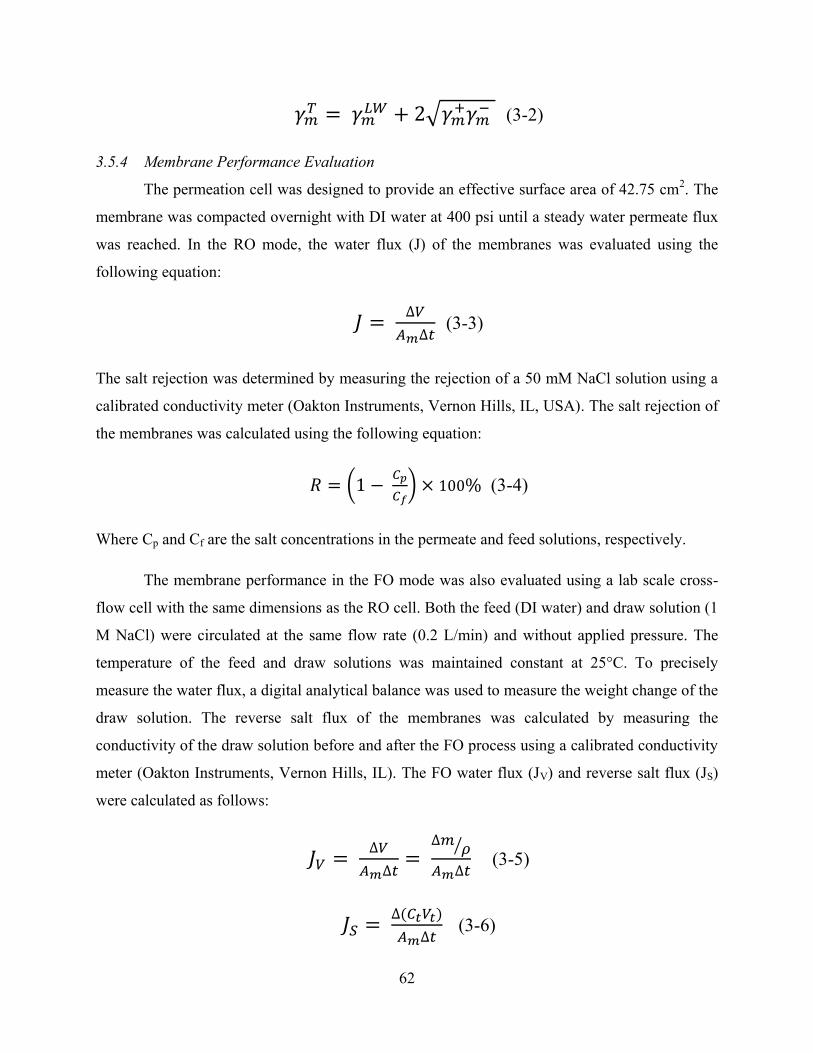
62
𝛾𝑚𝑇 = 𝛾𝑚
𝐿𝑊 + 2√𝛾𝑚+𝛾𝑚
− (3-2)
3.5.4 Membrane Performance Evaluation
The permeation cell was designed to provide an effective surface area of 42.75 cm2. The
membrane was compacted overnight with DI water at 400 psi until a steady water permeate flux
was reached. In the RO mode, the water flux (J) of the membranes was evaluated using the
following equation:
𝐽 = ∆𝑉
𝐴𝑚∆𝑡 (3-3)
The salt rejection was determined by measuring the rejection of a 50 mM NaCl solution using a
calibrated conductivity meter (Oakton Instruments, Vernon Hills, IL, USA). The salt rejection of
the membranes was calculated using the following equation:
𝑅 = (1 − 𝐶𝑝
𝐶𝑓) × 100% (3-4)
Where Cp and Cf are the salt concentrations in the permeate and feed solutions, respectively.
The membrane performance in the FO mode was also evaluated using a lab scale cross-
flow cell with the same dimensions as the RO cell. Both the feed (DI water) and draw solution (1
M NaCl) were circulated at the same flow rate (0.2 L/min) and without applied pressure. The
temperature of the feed and draw solutions was maintained constant at 25°C. To precisely
measure the water flux, a digital analytical balance was used to measure the weight change of the
draw solution. The reverse salt flux of the membranes was calculated by measuring the
conductivity of the draw solution before and after the FO process using a calibrated conductivity
meter (Oakton Instruments, Vernon Hills, IL). The FO water flux (JV) and reverse salt flux (JS)
were calculated as follows:
𝐽𝑉 = ∆𝑉
𝐴𝑚∆𝑡=
∆𝑚𝜌⁄
𝐴𝑚∆𝑡 (3-5)
𝐽𝑆 = ∆(𝐶𝑡𝑉𝑡)
𝐴𝑚∆𝑡 (3-6)

63
Where Δm is the weight change of the draw solution, Am is the effective surface area, and Ct and
Vt are the salt concentration and volume of the feed solution after the process, respectively.
3.5.5 Antimicrobial Evaluation of Membranes
Bacterial inactivation was evaluated by determining and comparing the number of viable
bacteria present on surfaces of virgin and functionalized membranes through a simple plate
counting method. Briefly, E. coli D21f2 (Gram negative and non-pathogenic) was grown
overnight at 37° C in Luria-Bertani (LB) broth medium. The bacterial solution was diluted and
cultured for 2 h to reach the log phase and was verified by an optical density measurement at 600
nm. The resulting bacterial solution was centrifuged and washed three times with 0.9% saline
solution before being diluted to 107 CFU mL
-1 in 0.9% saline solution. For the exposure phase,
1.5 cm2 membranes were punched and placed in a plastic holder with the active layer facing the
bacterial solution. The holders were maintained at room temperature for 1 h. After 1 h of
incubation, the excess solution was discarded, and the membranes were washed with a sterile
saline solution. To remove attached bacteria from the membrane surface, the membrane coupons
were bath sonicated for 7 min in a 10 mL isotonic solution. Finally, 100 µL serial dilutions
(representing over 6 orders of magnitude) of the bacterial solution were spread on LB agar plates
and incubated overnight at 37°C. The number of colonies was then counted.

64
Figure 27 Images of pristine, TFC-GO, TFC-Ag and TFC-GO-Ag-modified membranes.
TFC TFC-GO
TFC-Ag TFC-GO-Ag

65
Figure 28 FE-SEM images of pristine (A), GO-modified (B), Ag-modified (C) and GO-Ag-modified
membranes. White scale represents 100 nm.
(A) (B)
(C) (D)
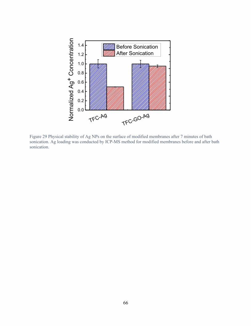
66
TFC-Ag
TFC-GO-Ag0.0
0.2
0.4
0.6
0.8
1.0
1.2
1.4
Norm
aliz
ed A
g+
Concentr
ation
Before Sonication
After Sonication
Figure 29 Physical stability of Ag NPs on the surface of modified membranes after 7 minutes of bath
sonication. Ag loading was conducted by ICP-MS method for modified membranes before and after bath
sonication.

67
Figure 30 XPS peak analysis for TFC, TFC-GO, and TFC-GO-Ag before and after regeneration. Results
show that after seven days of release, GO nanosheets are still present on the membrane surfaces.
280 285 290 295 300
B.E.(eV)
C=O (288.5)
C-O (286.4)
C-C (284.6)
Regenerated
280 285 290 295 300
B.E.(eV)
C=O (288.5)
C-O (286.4)
C-C (284.6)
TFC
280 285 290 295 300
C=O (288.5)
C-O (286.4)
C-C (284.6)
B.E.(eV)
TFC-GO
280 285 290 295 300
B.E.(eV)
C=O (288.5)
C-O (286.4)
C-C (284.6)
Released

68
Figure 31 SEM images of cells (E. coli D21f2) after contacting with pristine (A), GO-modified (B), Ag-
modified (C), and GO-Ag-modified (D) membranes for 1 h.
(A) (B)
(C) (D)

69
Table 3 Surface roughness properties of the pristine and functionalized TFC FO membranes.
Sample Rmax (nm) Ra (nm) Rq (nm) SAD (%)
TFC FO 486 ± 22 52.2 ± 0.5 65.5 ± 1.5 67.4 ± 2.1
TFC- Ag 483 ± 13 47.2 ± 2.8 59.1 ± 4.24 79.9 ± 2.2
TFC-GO-Ag 212±32 24.9±4.8 31.6±6 43.1±4.1

70
4 CONCLUSION and RECOMMENDATIONS
Biocidal Ag NPs and GO/Ag nanocomposite were synthesized and characterized.
Biocidal nanomaterials then applied in two different ways of ex situ and in situ onto the surface
of TFC FO membranes for preparing antimicrobial surfaces. Membrane characterization were
done and their performance evaluation were conducted were conducted in RO and FO mode of
operation. Results showed that making a composite of nanomaterials is more effective than each
one per se. biocidal nanocomposite can provide capture-killing mechanism and also will
inactivate bacteria in both media through releasing Ag+ ion and in contact through cell
membrane rupturing by GO nanosheets. GO nanosheets also could govern shape, size, and
distribution of Ag NPs and by decreasing the size and preventing aggregation will increase the
efficacy of biocidal properties. Covalent bonding of nanomaterials to the surface will increase
their stability. Although combination of nanomaterials has some advantages, it still suffering
from limited loading and fast depletion of Ag NPs through ion-release process without the
possibility of regeneration. To overcome those limitations, in situ formation of Ag NPs on the
surface of GO-treated TFC FO membranes were conducted to still enjoy the advantages of
combination of two different types of biocidal materials and increasing Ag loading content and
providing the regeneration possibility. In this approach, GO nanosheets were covalently bonded
onto the membrane surface and then Ag NPs formed in situ onto GO-modified surface through
wet chemical reduction of AgNO3 by NaBH4. Results showed new nanocomposite had the
similar biocidal properties with the former one but silver loading was greater and its release was
more controllable and longer lasted. Another advantage of new modification method was the
regeneration possibility. GO-Ag modified membranes were kept in DI water for seven days for
ion-release process then Ag NPs were regenerated in situ. Results showed after seven days GO
nanosheets remained on the surface but silver content decreased significantly. After regeneration
modified membranes regained their both hydrophilic and biocidal properties almost 80 percent.
New facile and quick regeneration method can be applied easily in real-world membrane systems
in different configurations such as hollow fiber and spiral wound modules.
Real biofouling tests for the future would be insightful for comprehensive understanding
of antibiofouling performance of modified membranes. Also investigation of toxicity and
bacterial inactivation mechanisms by the GO/Ag nanocomposite will provide more insights
about the synergetic effects of the combination of two biocidal nanomaterials. Combination of

71
polymer brushes with GO nanosheets also can be considered as an alternative of using biocidal
nanomaterials alone.

72
5 REFERENCES
1. Water for Sustainable World; United Nations Educational, Scientific and Cultural
Organization: France, 2015.
2. Patrick Gerland, A. E. R., Thomas Spoorenberg, Nevena Lalic, Leontine Alkema,
Guiomar Bay, Hana Ševčíková, Bailey K. Fosdick, Thomas Buettner, Nan Li, Danan Gu,
Jennifer Chunn, Gerhard K. Heilig, John Wilmoth, World population stabilization unlikely this
century. Science 2014, 346, 234-237.
3. C. J. Vör, A. Y. H., S. E. Bunn, D. Conway, J. Gupta Fresh Water Goes Global. Science
2015, 349, 478-479.
4. Elimelech, M.; Phillip, W. A., The future of seawater desalination: energy, technology,
and the environment. Science 2011, 333, (6043), 712-7.
5. Shannon, M. A.; Bohn, P. W.; Elimelech, M.; Georgiadis, J. G.; Marinas, B. J.; Mayes,
A. M., Science and technology for water purification in the coming decades. Nature 2008, 452,
(7185), 301-10.
6. Baker, R. W., Membrane Technology and Applications. 2nd ed.; John Wiley & Sons,
Ltd.: 2004.
7. Zhou, Y.; Tol, R. S. J., Evaluating the costs of desalination and water transport. Water
Resources Research 2005, 41, (3), n/a-n/a.
8. Veerapaneni, S. V. L., Bruce; Freeman, Scott; Bond, Rick, Reducing Energy
Consumption for Seawater Desalination. J. Am. Water Works Assoc. 2007, 99, (6), 95-106.
9. Shaffer, D. L.; Werber, J. R.; Jaramillo, H.; Lin, S.; Elimelech, M., Forward osmosis:
Where are we now? Desalination 2015, 356, 271-284.
10. Achilli, A.; Cath, T. Y.; Childress, A. E., Selection of inorganic-based draw solutions for
forward osmosis applications. Journal of Membrane Science 2010, 364, (1-2), 233-241.
11. Ge, Q.; Ling, M.; Chung, T.-S., Draw solutions for forward osmosis processes:
Developments, challenges, and prospects for the future. Journal of Membrane Science 2013,
442, 225-237.
12. Romero-Vargas Castrillón, S.; Lu, X.; Shaffer, D. L.; Elimelech, M., Amine enrichment
and poly(ethylene glycol) (PEG) surface modification of thin-film composite forward osmosis
membranes for organic fouling control. Journal of Membrane Science 2014, 450, 331-339.
13. Mi, B.; Elimelech, M., Chemical and physical aspects of organic fouling of forward
osmosis membranes. Journal of Membrane Science 2008, 320, (1-2), 292-302.
14. Mi, B.; Elimelech, M., Organic fouling of forward osmosis membranes: Fouling
reversibility and cleaning without chemical reagents. Journal of Membrane Science 2010, 348,
(1-2), 337-345.
15. Kim, Y.; Elimelech, M.; Shon, H. K.; Hong, S., Combined organic and colloidal fouling
in forward osmosis: Fouling reversibility and the role of applied pressure. Journal of Membrane
Science 2014, 460, 206-212.
16. Mi, B.; Elimelech, M., Silica scaling and scaling reversibility in forward osmosis.
Desalination 2013, 312, 75-81.

73
17. Boo, C.; Elimelech, M.; Hong, S., Fouling control in a forward osmosis process
integrating seawater desalination and wastewater reclamation. Journal of Membrane Science
2013, 444, 148-156.
18. D. Rana , T. M., Surface Modifications for Antifouling Membranes. Chem. Rev. 2010,
110, 2448–2471.
19. Rahaman, M. S.; Thérien-Aubin, H.; Ben-Sasson, M.; Ober, C. K.; Nielsen, M.;
Elimelech, M., Control of biofouling on reverse osmosis polyamide membranes modified with
biocidal nanoparticles and antifouling polymer brushes. Journal of Materials Chemistry B 2014,
2, (12), 1724.
20. Tiraferri, A.; Kang, Y.; Giannelis, E. P.; Elimelech, M., Highly hydrophilic thin-film
composite forward osmosis membranes functionalized with surface-tailored nanoparticles. ACS
Appl Mater Interfaces 2012, 4, (9), 5044-53.
21. Tiraferri, A.; Vecitis, C. D.; Elimelech, M., Covalent binding of single-walled carbon
nanotubes to polyamide membranes for antimicrobial surface properties. ACS Appl Mater
Interfaces 2011, 3, (8), 2869-77.
22. Mark R. Wiesner, J.-Y. B., Environmental nanotechnology. McGraw Hill: 2007.
23. Marambio-Jones, C.; Hoek, E. M. V., A review of the antibacterial effects of silver
nanomaterials and potential implications for human health and the environment. Journal of
Nanoparticle Research 2010, 12, (5), 1531-1551.
24. Halas, J. B. J. a. N. J., Silver Nanoshells: Variations in Morphologies and Optical
Properties. J. Phys. Chem. B 2001, 105, 2743-2746.
25. Sun, Y.; Xia, Y., Shape-controlled synthesis of gold and silver nanoparticles. Science
2002, 298, (5601), 2176-9.
26. Martínez-Castañón, G. A.; Niño-Martínez, N.; Loyola-Rodríguez, J. P.; Patiño-Marín, N.;
Martínez-Mendoza, J. R.; Ruiz, F., Synthesis of silver particles with different sizes and
morphologies. Materials Letters 2009, 63, (15), 1266-1268.
27. Neil Shirtcliffe, U. N., 1 and Siegfried Schneider, Reproducible Preparation of Silver
Sols with Small Particle Size Using Borohydride Reduction: For Use as Nuclei for Preparation of
Larger Particles. Journal of Colloid and Interface Science 1999, 211, 122–129.
28. Wiley, B.; Sun, Y.; Mayers, B.; Xia, Y., Shape-controlled synthesis of metal
nanostructures: the case of silver. Chemistry 2005, 11, (2), 454-63.
29. Jo¨ rg Polte, K. R., Xenia Tuaev, Maria Wuithschick, Ralph Kraehnert, Anna Fischer,
Andreas F. Thuenemann, and Franziska Emmerling, Formation Mechanism of Colloidal Silver
Nanoparticles: Analogies and Differences to the Growth of Gold Nanoparticles. ASC NANO
2012, 6, (7), 5791–5802
30. Arnim Henglein, M. G., Formation of Colloidal Silver Nanoparticles: Capping Action of
Citrate. J. Phys. Chem. B 1999, , 103, 9533-9539.
31. Keating, M.; Chen, Y.; Larmour, I. A.; Faulds, K.; Graham, D., Growth and surface-
enhanced Raman scattering of Ag nanoparticle assembly in agarose gel. Measurement Science
and Technology 2012, 23, (8), 084006.
32. C. Carlson, S. M. H., A. M. Schrand, L. K. Braydich-Stolle, K. L. Hess, R. L. Jones, and
J. J. Schlager, Unique Cellular Interaction of Silver Nanoparticles: Size-Dependent Generation of
Reactive Oxygen Species. J. Phys. Chem. B 13608–13619 2008, 112, 13608–13619.
33. Xiu, Z. M.; Zhang, Q. B.; Puppala, H. L.; Colvin, V. L.; Alvarez, P. J., Negligible
particle-specific antibacterial activity of silver nanoparticles. Nano Lett 2012, 12, (8), 4271-5.

74
34. Morones, J. R.; Elechiguerra, J. L.; Camacho, A.; Holt, K.; Kouri, J. B.; Ramirez, J. T.;
Yacaman, M. J., The bactericidal effect of silver nanoparticles. Nanotechnology 2005, 16, (10),
2346-53.
35. Pal, S.; Tak, Y. K.; Song, J. M., Does the antibacterial activity of silver nanoparticles
depend on the shape of the nanoparticle? A study of the Gram-negative bacterium Escherichia
coli. Appl Environ Microbiol 2007, 73, (6), 1712-20.
36. Libor Kvı´tek, A. P. c. e., Jana Soukupova´, Milan Kola´rˇ, Renata Vecˇerˇova´, Robert
Prucek, Mirka Holecova´, and Radek Zborˇil, Effect of Surfactants and Polymers on Stability
and Antibacterial Activity of Silver Nanoparticles (NPs). J. Phys. Chem. C 2008, 112, 5825-
5834.
37. Alexander B. Smetana, K. J. K., George R. Marchin, and Christopher M. Sorensen,
Biocidal Activity of Nanocrystalline Silver Powders and Particles. Langmuir 2008, 24, 7457-
7464.
38. Nel, A. E.; Madler, L.; Velegol, D.; Xia, T.; Hoek, E. M.; Somasundaran, P.; Klaessig,
F.; Castranova, V.; Thompson, M., Understanding biophysicochemical interactions at the nano-
bio interface. Nat Mater 2009, 8, (7), 543-57.
39. Zodrow, K.; Brunet, L.; Mahendra, S.; Li, D.; Zhang, A.; Li, Q.; Alvarez, P. J.,
Polysulfone ultrafiltration membranes impregnated with silver nanoparticles show improved
biofouling resistance and virus removal. Water Res 2009, 43, (3), 715-23.
40. Mauter, M. S.; Wang, Y.; Okemgbo, K. C.; Osuji, C. O.; Giannelis, E. P.; Elimelech, M.,
Antifouling ultrafiltration membranes via post-fabrication grafting of biocidal nanomaterials.
ACS Appl Mater Interfaces 2011, 3, (8), 2861-8.
41. Sawada, I.; Fachrul, R.; Ito, T.; Ohmukai, Y.; Maruyama, T.; Matsuyama, H.,
Development of a hydrophilic polymer membrane containing silver nanoparticles with both
organic antifouling and antibacterial properties. Journal of Membrane Science 2012, 387-388, 1-
6.
42. Kim, E.-S.; Hwang, G.; Gamal El-Din, M.; Liu, Y., Development of nanosilver and
multi-walled carbon nanotubes thin-film nanocomposite membrane for enhanced water
treatment. Journal of Membrane Science 2012, 394-395, 37-48.
43. Liu, X.; Qi, S.; Li, Y.; Yang, L.; Cao, B.; Tang, C. Y., Synthesis and characterization of
novel antibacterial silver nanocomposite nanofiltration and forward osmosis membranes based
on layer-by-layer assembly. Water Res 2013, 47, (9), 3081-92.
44. Madhavan, P.; Hong, P. Y.; Sougrat, R.; Nunes, S. P., Silver-enhanced block copolymer
membranes with biocidal activity. ACS Appl Mater Interfaces 2014, 6, (21), 18497-501.
45. Guidelines for drinking-water quality, 2nd ed. Vol. 2. Health criteria and other
supporting information. World Health Organization; World Health Organization: Geneva, 1996.
46. Yin, J.; Yang, Y.; Hu, Z.; Deng, B., Attachment of silver nanoparticles (AgNPs) onto
thin-film composite (TFC) membranes through covalent bonding to reduce membrane
biofouling. Journal of Membrane Science 2013, 441, 73-82.
47. Ben-Sasson, M.; Lu, X.; Bar-Zeev, E.; Zodrow, K. R.; Nejati, S.; Qi, G.; Giannelis, E. P.;
Elimelech, M., In situ formation of silver nanoparticles on thin-film composite reverse osmosis
membranes for biofouling mitigation. Water Res 2014, 62, 260-70.
48. Tang, L.; Livi, K. J. T.; Chen, K. L., Polysulfone Membranes Modified with Bioinspired
Polydopamine and Silver Nanoparticles Formedin SituTo Mitigate Biofouling. Environmental
Science & Technology Letters 2015, 2, (3), 59-65.

75
49. Tang, L.; Huynh, K. A.; Fleming, M. L.; Larronde-Larretche, M.; Chen, K. L., Imparting
antimicrobial and anti-adhesive properties to polysulfone membranes through modification with
silver nanoparticles and polyelectrolyte multilayers. J Colloid Interface Sci 2015, 451, 125-33.
50. K. S. Novoselov, A. K. G., S. V. Morozov, D. Jiang, Y. Zhang, S. V. Dubonos, I. V.
Grigorieva, A. A. Firsov, Electric Field Effect in Atomically Thin Carbon Films. Science 2004,
306 C, 666-669.
51. Dresselhaus, M. S.; Araujo, P. T., Perspectives on the 2010 Nobel Prize in Physics for
Graphene. ACS Nano 2010, 4, (11), 6297-6302.
52. Wee, A. T., Graphene: the game changer? ACS Nano 2012, 6, (7), 5739-41.
53. Compton, O. C.; Nguyen, S. T., Graphene oxide, highly reduced graphene oxide, and
graphene: versatile building blocks for carbon-based materials. Small 2010, 6, (6), 711-23.
54. Sreeprasad, T. S.; Berry, V., How do the electrical properties of graphene change with its
functionalization? Small 2013, 9, (3), 341-50.
55. Changgu Lee, X. W., Jeffrey W. Kysar, James Hone, Measurement of the Elastic
Properties and Intrinsic Strength of Monolayer Graphene. Science 2008, 321, 385-388.
56. Huang, X.; Qi, X.; Boey, F.; Zhang, H., Graphene-based composites. Chem Soc Rev
2012, 41, (2), 666-86.
57. Hummers, W. S.; Offeman, R. E., Preparation of Graphitic Oxide. Journal of the
American Chemical Society 1958, 80, (6), 1339-1339.
58. Sanchez, V. C.; Jachak, A.; Hurt, R. H.; Kane, A. B., Biological interactions of graphene-
family nanomaterials: an interdisciplinary review. Chem Res Toxicol 2012, 25, (1), 15-34.
59. Yang, K.; Li, Y.; Tan, X.; Peng, R.; Liu, Z., Behavior and toxicity of graphene and its
functionalized derivatives in biological systems. Small 2013, 9, (9-10), 1492-503.
60. Jastrzebska, A. M.; Kurtycz, P.; Olszyna, A. R., Recent advances in graphene family
materials toxicity investigations. J Nanopart Res 2012, 14, (12), 1320.
61. Zhou, X.; Huang, X.; Qi, X.; Wu, S.; Xue, C.; Boey, F. Y. C.; Yan, Q.; Chen, P.; Zhang,
H., In Situ Synthesis of Metal Nanoparticles on Single-Layer Graphene Oxide and Reduced
Graphene Oxide Surfaces. The Journal of Physical Chemistry C 2009, 113, (25), 10842-10846.
62. Muszynski, R.; Seger, B.; Kamat, P. V., Decorating Graphene Sheets with Gold
Nanoparticles. The Journal of Physical Chemistry C 2008, 112, (14), 5263-5266.
63. Zhu, Z.; Su, M.; Ma, L.; Ma, L.; Liu, D.; Wang, Z., Preparation of graphene oxide-silver
nanoparticle nanohybrids with highly antibacterial capability. Talanta 2013, 117, 449-55.
64. Li, J.; Kuang, D.; Feng, Y.; Zhang, F.; Xu, Z.; Liu, M.; Wang, D., Green synthesis of
silver nanoparticles-graphene oxide nanocomposite and its application in electrochemical
sensing of tryptophan. Biosens Bioelectron 2013, 42, 198-206.
65. Vijay Kumar, S.; Huang, N. M.; Lim, H. N.; Marlinda, A. R.; Harrison, I.; Chia, C. H.,
One-step size-controlled synthesis of functional graphene oxide/silver nanocomposites at room
temperature. Chemical Engineering Journal 2013, 219, 217-224.
66. Li, C.; Wang, X.; Chen, F.; Zhang, C.; Zhi, X.; Wang, K.; Cui, D., The antifungal activity
of graphene oxide-silver nanocomposites. Biomaterials 2013, 34, (15), 3882-90.
67. Hassan, H. M. A.; Abdelsayed, V.; Khder, A. E. R. S.; AbouZeid, K. M.; Terner, J.; El-
Shall, M. S.; Al-Resayes, S. I.; El-Azhary, A. A., Microwave synthesis of graphene sheets
supporting metal nanocrystals in aqueous and organic media. Journal of Materials Chemistry
2009, 19, (23), 3832.

76
68. Liu, J.; Fu, S.; Yuan, B.; Li, Y.; Deng, Z., Toward a universal "adhesive nanosheet" for
the assembly of multiple nanoparticles based on a protein-induced reduction/decoration of
graphene oxide. J Am Chem Soc 2010, 132, (21), 7279-81.
69. Du, J.; Lai, X.; Yang, N.; Zhai, J.; Kisailus, D.; Su, F.; Wang, D.; Jiang, L.,
Hierarchically ordered macro-mesoporous TiO(2)-graphene composite films: improved mass
transfer, reduced charge recombination, and their enhanced photocatalytic activities. ACS Nano
2011, 5, (1), 590-6.
70. Hwang, J. O.; Lee, D. H.; Kim, J. Y.; Han, T. H.; Kim, B. H.; Park, M.; No, K.; Kim, S.
O., Vertical ZnO nanowires/graphene hybrids for transparent and flexible field emission. J.
Mater. Chem. 2011, 21, (10), 3432-3437.
71. Perreault, F.; Fonseca de Faria, A.; Elimelech, M., Environmental applications of
graphene-based nanomaterials. Chem Soc Rev 2015.
72. Guo, F.; Silverberg, G.; Bowers, S.; Kim, S. P.; Datta, D.; Shenoy, V.; Hurt, R. H.,
Graphene-based environmental barriers. Environ Sci Technol 2012, 46, (14), 7717-24.
73. Cohen-Tanugi, D.; Grossman, J. C., Water desalination across nanoporous graphene.
Nano Lett 2012, 12, (7), 3602-8.
74. Hu, M.; Mi, B., Enabling graphene oxide nanosheets as water separation membranes.
Environ Sci Technol 2013, 47, (8), 3715-23.
75. Lee, J.; Chae, H.-R.; Won, Y. J.; Lee, K.; Lee, C.-H.; Lee, H. H.; Kim, I.-C.; Lee, J.-m.,
Graphene oxide nanoplatelets composite membrane with hydrophilic and antifouling properties
for wastewater treatment. Journal of Membrane Science 2013, 448, 223-230.
76. Ionita, M.; Pandele, A. M.; Crica, L.; Pilan, L., Improving the thermal and mechanical
properties of polysulfone by incorporation of graphene oxide. Composites Part B: Engineering
2014, 59, 133-139.
77. Choi, W.; Choi, J.; Bang, J.; Lee, J. H., Layer-by-layer assembly of graphene oxide
nanosheets on polyamide membranes for durable reverse-osmosis applications. ACS Appl Mater
Interfaces 2013, 5, (23), 12510-9.
78. Perreault, F.; Tousley, M. E.; Elimelech, M., Thin-Film Composite Polyamide
Membranes Functionalized with Biocidal Graphene Oxide Nanosheets. Environmental Science
& Technology Letters 2014, 1, (1), 71-76.
79. Goh, K.; Setiawan, L.; Wei, L.; Si, R.; Fane, A. G.; Wang, R.; Chen, Y., Graphene oxide
as effective selective barriers on a hollow fiber membrane for water treatment process. Journal
of Membrane Science 2015, 474, 244-253.
80. Hu, M.; Mi, B., Layer-by-layer assembly of graphene oxide membranes via electrostatic
interaction. Journal of Membrane Science 2014, 469, 80-87.
81. Huang, L.; Zhang, M.; Li, C.; Shi, G., Graphene-Based Membranes for Molecular
Separation. J Phys Chem Lett 2015, 6, (14), 2806-15.
82. McGinnis, R. L.; Elimelech, M., Energy requirements of ammonia–carbon dioxide
forward osmosis desalination. Desalination 2007, 207, (1-3), 370-382.
83. Matin, A.; Khan, Z.; Zaidi, S. M. J.; Boyce, M. C., Biofouling in reverse osmosis
membranes for seawater desalination: Phenomena and prevention. Desalination 2011, 281, 1-16.
84. Siddiqui, M. F.; Rzechowicz, M.; Oh, H.-S.; Saeidi, N.; Hui, L. J.; Winters, H.; Fane, A.
G.; Chong, T. H., The efficacy of tannic acid in controlling biofouling by Pseudomonas
aeruginosa is dependent on nutrient conditions and bacterial density. International
Biodeterioration & Biodegradation 2015, 104, 74-82.
77
85. Cristiani, P.; Perboni, G., Antifouling strategies and corrosion control in cooling circuits.
Bioelectrochemistry 2014, 97, 120-6.
86. D. Rana, T. M., Surface Modifications for Antifouling Membranes. Chem. Rev 2010,
110, 2448-2471.
87. Kang, G. D.; Cao, Y. M., Development of antifouling reverse osmosis membranes for
water treatment: A review. Water Res 2012, 46, (3), 584-600.
88. Lu, X.; Romero-Vargas Castrillon, S.; Shaffer, D. L.; Ma, J.; Elimelech, M., In situ
surface chemical modification of thin-film composite forward osmosis membranes for enhanced
organic fouling resistance. Environ Sci Technol 2013, 47, (21), 12219-28.
89. Asatekin, A.; Olivetti, E. A.; Mayes, A. M., Fouling resistant, high flux nanofiltration
membranes from polyacrylonitrile-graft-poly(ethylene oxide). Journal of Membrane Science
2009, 332, (1-2), 6-12.
90. Atar Adout , S. K., Ayse Asatekin, Anne M. Mayes and Menachem Elimelech
Ultrafiltration Membranes Incorporating Amphiphilic Comb Copolymer Additives Prevent
Irreversible Adhesion of Bacteria. environmental Science & Technology 2010, 44, (7), 2406–
2411.
91. Nguyen, A.; Zou, L.; Priest, C., Evaluating the antifouling effects of silver nanoparticles
regenerated by TiO2 on forward osmosis membrane. Journal of Membrane Science 2014, 454,
264-271.
92. Gao, Y.; Hu, M.; Mi, B., Membrane surface modification with TiO2–graphene oxide for
enhanced photocatalytic performance. Journal of Membrane Science 2014, 455, 349-356.
93. Vecitis, C. D.; Schnoor, M. H.; Rahaman, M. S.; Schiffman, J. D.; Elimelech, M.,
Electrochemical multiwalled carbon nanotube filter for viral and bacterial removal and
inactivation. Environ Sci Technol 2011, 45, (8), 3672-9.
94. P. Cristiani a, G. P. b., Antifouling strategies and corrosion control in cooling circuits.
Bioelectrochemistry 2014, 97, 120-126.
95. Zhu, Y.; Murali, S.; Cai, W.; Li, X.; Suk, J. W.; Potts, J. R.; Ruoff, R. S., Graphene and
graphene oxide: synthesis, properties, and applications. Adv Mater 2010, 22, (35), 3906-24.
96. Mi, B., Materials science. Graphene oxide membranes for ionic and molecular sieving.
Science 2014, 343, (6172), 740-2.
97. Joshi, R. K.; Carbone, P.; Wang, F. C.; Kravets, V. G.; Su, Y.; Grigorieva, I. V.; Wu, H.
A.; Geim, A. K.; Nair, R. R., Precise and ultrafast molecular sieving through graphene oxide
membranes. Science 2014, 343, (6172), 752-4.
98. Celebi, K.; Buchheim, J.; Wyss, R. M.; Droudian, A.; Gasser, P.; Shorubalko, I.; Kye, J.
I.; Lee, C.; Park, H. G., Ultimate permeation across atomically thin porous graphene. Science
2014, 344, (6181), 289-92.
99. Das, M. R.; Sarma, R. K.; Saikia, R.; Kale, V. S.; Shelke, M. V.; Sengupta, P., Synthesis
of silver nanoparticles in an aqueous suspension of graphene oxide sheets and its antimicrobial
activity. Colloids Surf B Biointerfaces 2011, 83, (1), 16-22.
100. de Faria, A. F.; Martinez, D. S.; Meira, S. M.; de Moraes, A. C.; Brandelli, A.; Filho, A.
G.; Alves, O. L., Anti-adhesion and antibacterial activity of silver nanoparticles supported on
graphene oxide sheets. Colloids Surf B Biointerfaces 2014, 113, 115-24.
101. Ocsoy, I.; Paret, M. L.; Ocsoy, M. A.; Kunwar, S.; Chen, T.; You, M.; Tan, W.,
Nanotechnology in Plant Disease Management: DNA-Directed Silver Nanoparticles on
Graphene Oxide as an Antibacterial against Xanthomonas perforans. ACS Nano 2013, 7, (10),
8972-8980.

78
102. Thierry Cassagneau, J. H. F., Preparation and Layer-by-Layer Self-Assembly of Silver
Nanoparticles Capped by Graphite Oxide Nanosheets. J. Phys. Chem. B 1999, 103, 1789-1793.
103. W.S. Hummers, R. E. O., Preparation of Graphitic Oxid. J. Am. Chem. Soc. 1958, 80,
1339.
104. Cath, T. Y.; Elimelech, M.; McCutcheon, J. R.; McGinnis, R. L.; Achilli, A.; Anastasio,
D.; Brady, A. R.; Childress, A. E.; Farr, I. V.; Hancock, N. T.; Lampi, J.; Nghiem, L. D.; Xie,
M.; Yip, N. Y., Standard Methodology for Evaluating Membrane Performance in Osmotically
Driven Membrane Processes. Desalination 2013, 312, 31-38.
105. Wenzel, R. N., SURFACE ROUGHNESS AND CONTACT ANGLE. J. Phys. Chem
1949, 53, 1466-1467.
106. Hurwitz, G.; Guillen, G. R.; Hoek, E. M. V., Probing polyamide membrane surface
charge, zeta potential, wettability, and hydrophilicity with contact angle measurements. Journal
of Membrane Science 2010, 349, (1-2), 349-357.
107. Sharon L. Walker, S. B., Eric M. V. Hoek, and; Elimelech, M., A Novel Asymmetric
Clamping Cell for Measuring Streaming Potential of Flat Surfaces. Langmuir 2002, 18, 2193-
2198.
108. Lee, J. U.; Lee, W.; Yoon, S. S.; Kim, J.; Byun, J. H., Site-selective immobilization of
gold nanoparticles on graphene sheets and its electrochemical properties. Applied Surface
Science 2014, 315, 73-80.
109. Tian, J.; Liu, S.; Zhang, Y.; Li, H.; Wang, L.; Luo, Y.; Asiri, A. M.; Al-Youbi, A. O.;
Sun, X., Environmentally friendly, one-pot synthesis of Ag nanoparticle-decorated reduced
graphene oxide composites and their application to photocurrent generation. Inorganic chemistry
2012, 51, (8), 4742-6.
110. Eric M. Vrijenhoek , S. H., Menachem Elimelech, Influence of membrane surface
properties on initial rate of colloidal fouling of reverse osmosis and nanofiltration membranes.
journal of Membrane Science 2001, 185, 115-128.
111. Xu, W.-P.; Zhang, L.-C.; Li, J.-P.; Lu, Y.; Li, H.-H.; Ma, Y.-N.; Wang, W.-D.; Yu, S.-H.,
Facile synthesis of silver@graphene oxide nanocomposites and their enhanced antibacterial
properties. Journal of Materials Chemistry 2011, 21, (12), 4593.
112. Li, Y.; Yuan, H.; von dem Bussche, A.; Creighton, M.; Hurt, R. H.; Kane, A. B.; Gao, H.,
Graphene microsheets enter cells through spontaneous membrane penetration at edge asperities
and corner sites. Proc Natl Acad Sci U S A 2013, 110, (30), 12295-300.
113. Li, W. R.; Xie, X. B.; Shi, Q. S.; Zeng, H. Y.; Ou-Yang, Y. S.; Chen, Y. B., Antibacterial
activity and mechanism of silver nanoparticles on Escherichia coli. Appl Microbiol Biotechnol
2010, 85, (4), 1115-22.
114. Ismail Ocsoy, M. L. P., Muserref Arslan Ocsoy, Sanju Kunwar, Tao Chen, Weihong Tan,
Mingxu You,, Nanotechnology in Plant Disease Management: DNA-Directed Silver
Nanoparticles on Graphene Oxide as an Antibacterial against Xanthomonas perforans. ACS Nano
2013, 7, (10), 8972-8990.
115. Romero-Vargas Castrillón, S.; Perreault, F.; de Faria, A. F.; Elimelech, M., Interaction of
Graphene Oxide with Bacterial Cell Membranes: Insights from Force Spectroscopy.
Environmental Science & Technology Letters 2015, 2, (4), 112-117.
116. MARK R. WIESNER, S. C., The promise of membrane technology. Environ Sci Technol
1999, 33, (17), 360A-366A.
117. Pendergast, M. M.; Hoek, E. M. V., A review of water treatment membrane
nanotechnologies. Energy & Environmental Science 2011, 4, (6), 1946.

79
118. Ben-Sasson, M.; Zodrow, K. R.; Genggeng, Q.; Kang, Y.; Giannelis, E. P.; Elimelech,
M., Surface functionalization of thin-film composite membranes with copper nanoparticles for
antimicrobial surface properties. Environ Sci Technol 2014, 48, (1), 384-93.
119. Zhou, Z.; Calabrese, D. R.; Taylor, W.; Finlay, J. A.; Callow, M. E.; Callow, J. A.;
Fischer, D.; Kramer, E. J.; Ober, C. K., Amphiphilic triblock copolymers with PEGylated
hydrocarbon structures as environmentally friendly marine antifouling and fouling-release
coatings. Biofouling 2014, 30, (5), 589-604.
120. Thanh, N. T.; Maclean, N.; Mahiddine, S., Mechanisms of nucleation and growth of
nanoparticles in solution. Chem Rev 2014, 114, (15), 7610-30.
121. Liao, H. G.; Niu, K.; Zheng, H., Observation of growth of metal nanoparticles. Chem
Commun (Camb) 2013, 49, (100), 11720-7.
122. Daer, S.; Kharraz, J.; Giwa, A.; Hasan, S. W., Recent applications of nanomaterials in
water desalination: A critical review and future opportunities. Desalination 2015, 367, 37-48.
123. Chao Xu, X. W., and Junwu Zhu, Graphene-Metal Particle Nanocomposites. J. Phys.
Chem. C 2008, 112, 19841–19845
124. Dreyer, D. R.; Park, S.; Bielawski, C. W.; Ruoff, R. S., The chemistry of graphene oxide.
Chem Soc Rev 2010, 39, (1), 228-40.
125. Shaobin Liu, J. K., Tingying Helen Zeng, Chen Mario Hofmann, Ehdi Burcombe, Jun
Wei, Rongrong Jiang, and Yuan, Antibacterial Activity of Graphite, Graphite Oxide, Graphene
Oxide, and Reduced Graphene Oxide: Membrane and Oxidative Stress. ASC NANO 2011, 5, (9),
6971–6980.
126. Chen, J.; Peng, H.; Wang, X.; Shao, F.; Yuan, Z.; Han, H., Graphene oxide exhibits
broad-spectrum antimicrobial activity against bacterial phytopathogens and fungal conidia by
intertwining and membrane perturbation. Nanoscale 2014, 6, (3), 1879-89.
127. Mejias Carpio, I. E.; Santos, C. M.; Wei, X.; Rodrigues, D. F., Toxicity of a polymer-
graphene oxide composite against bacterial planktonic cells, biofilms, and mammalian cells.
Nanoscale 2012, 4, (15), 4746-56.
128. Zhang, D.; Liu, X.; Wang, X., Green synthesis of graphene oxide sheets decorated by
silver nanoprisms and their anti-bacterial properties. J Inorg Biochem 2011, 105, (9), 1181-6.
129. de Faria, A. F.; Perreault, F.; Shaulsky, E.; Arias Chavez, L. H.; Elimelech, M.,
Antimicrobial Electrospun Biopolymer Nanofiber Mats Functionalized with Graphene Oxide-
Silver Nanocomposites. ACS Appl Mater Interfaces 2015, 7, (23), 12751-9.
130. Soroush, A.; Ma, W.; Silvino, Y.; Rahaman, M. S., Surface modification of thin film
composite forward osmosis membrane by silver-decorated graphene-oxide nanosheets. Environ.
Sci.: Nano 2015, 2, (4), 395-405.
131. Eric M. Vrijen Hoek, S. H., Menachem Elimelech, Influence of membrane surface
properties on initial rate of colloidal fouling of reverse osmosis and nanofiltration membranes.
Journal of Membrane Science 2001, 185, 115-128.
132. Oss, C. J. v., The Properties of Water and their Role in Colloidal and Biological Systems.
Academic Press: Amsterdam, 2008; Vol. vol. 16.
133. van Oss, C. J., Development and applications of the interfacial tension between water and
organic or biological surfaces. Colloids Surf B Biointerfaces 2007, 54, (1), 2-9.
134. Franc-ois Perreault, A. F. d. F., Siamak Nejati, Menachem Elimelech, Antimicrobial
Properties of Graphene Oxide Nanosheets: Why Size Matters. ACS Nano 2015.

80
135. Agnihotri, S.; Mukherji, S.; Mukherji, S., Size-controlled silver nanoparticles synthesized
over the range 5–100 nm using the same protocol and their antibacterial efficacy. RSC Adv.
2014, 4, (8), 3974-3983.