development of bolt-on low profile overflow / orifice pit tag antennas for john day dam adult...
TRANSCRIPT
Development of Bolt-on Low Profile Overflow / Orifice PIT Tag Antennas for John Day Dam Adult Ladders
PTAGIS Field OfficeKennewick, Washington
November 2014
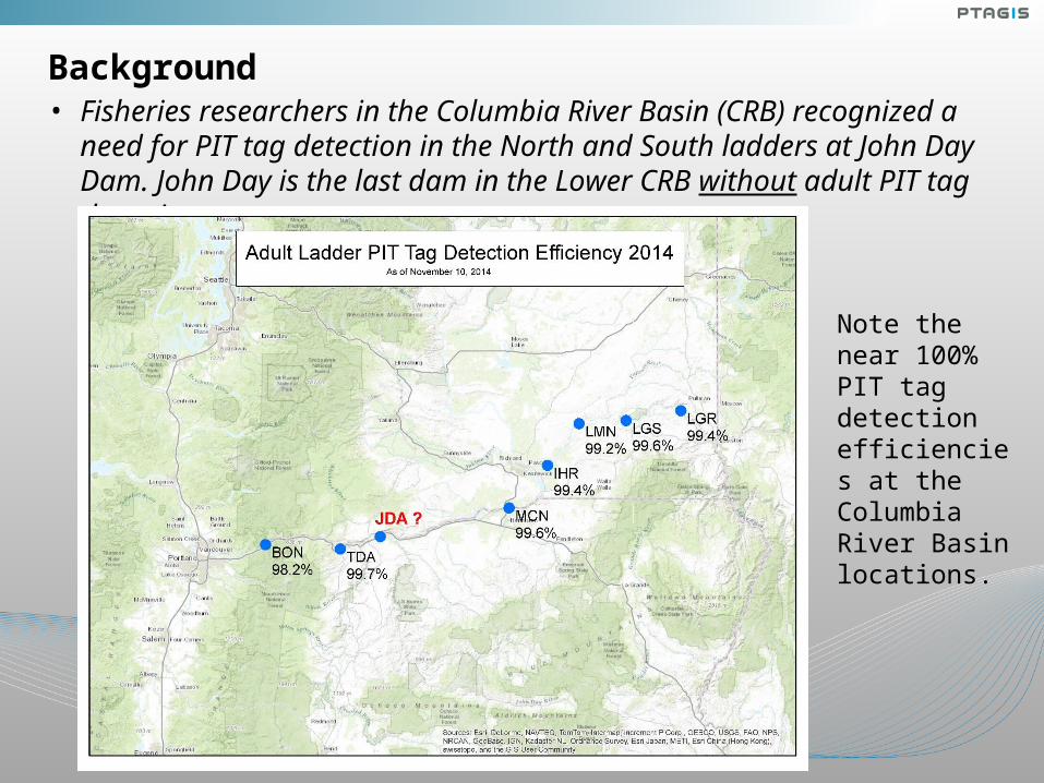
Background• Fisheries researchers in the Columbia River Basin (CRB) recognized a need for
PIT tag detection in the North and South ladders at John Day Dam. John Day is the last dam in the Lower CRB without adult PIT tag detection.
Note the near 100% PIT tag detection efficiencies at the Columbia River Basin locations.

Background• After several visits to John Day, it was determined the existing infrastructure
surrounding the North and South counting window locations would require extensive renovation and would not be cost effective to install PIT tag antennas.
John Day North Counting Window John Day South Counting Window

Vertical Slots were Examined in 2012.
In late winter of 2012, a proposal was sent to FFDRWG members. This proposal required concrete cutting to install the antennas at these locations.
It was then determined that the overflow weir sections would be a cost effective candidate. This option would meet the near 100% detection efficiency standards at all other PSMFC maintained adult fish ladders.

Background
• In 2012, PSMFC successfully developed a thin body ferrite tile antenna in the PSMFC Kennewick Lab.
• In 2013-14, these thin body style antennas were successfully installed in counting window locations at The Dalles, Little Goose and Lower Monumental dams.

Background
• After a complete review of all other installation options, the overflow and orifice weirs were chosen as the best target locations.
• Antenna development surrounding the overflow and orifice
weirs was initiated.
• The following slide contains the conceptual drawing demonstrating how four antennas would be installed on any existing overflow weir wall.
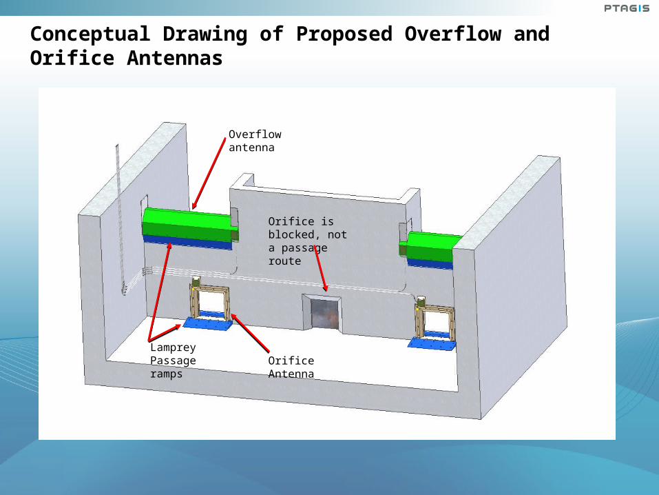
Conceptual Drawing of Proposed Overflow and Orifice Antennas
Overflow antenna
Lamprey Passage ramps Orifice Antenna
Orifice is blocked, not a passage route

In the Summer of 2014, A Thin Body Overflow Antenna was Developed by Kennewick PSMFC Staff and Tested at the Pasco NOAA Facility.
Antenna Benefits:
• Antenna is a Ferrite Tile Thin Body Flat-Plate design.
• The antenna is approximately 2 inches total thickness.
• Antenna is contoured to match the geometry of the weirs overflow notch.
• Designed to fit the entire width of the weir wall notch.
• Antenna design is effectively immune to ferrous materials that may be in the weir notch and adjacent walls.
• Minimal hydraulic disruption.
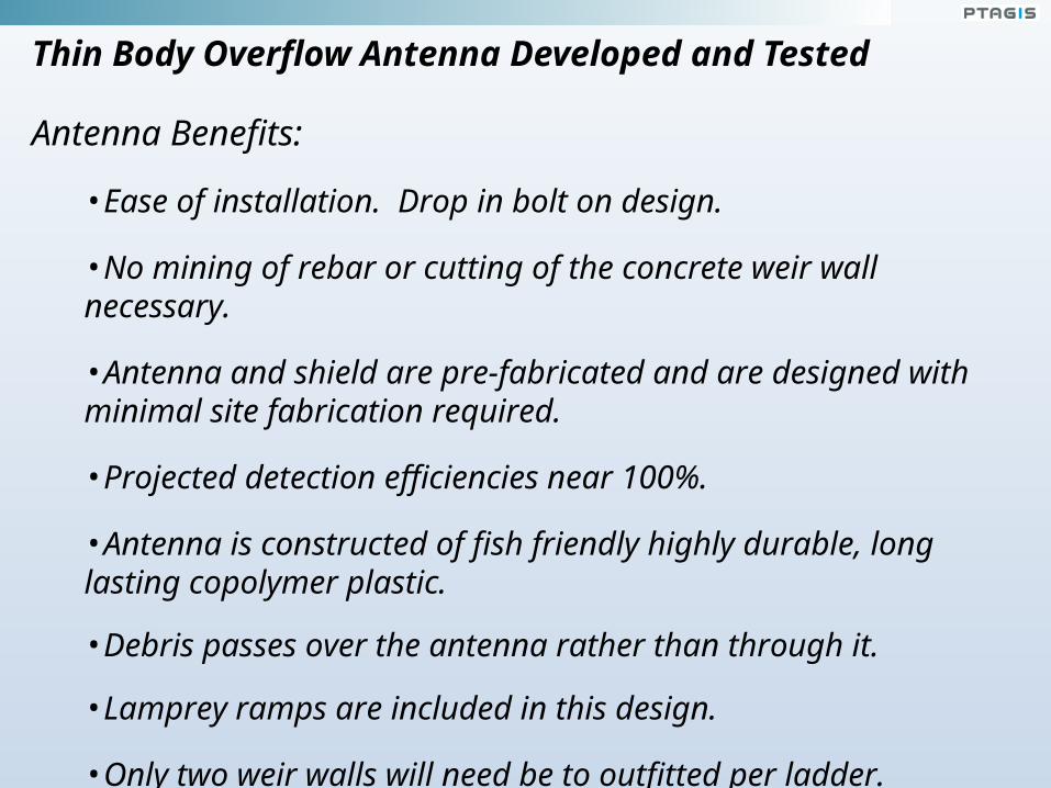
Thin Body Overflow Antenna Developed and Tested
Antenna Benefits:
•Ease of installation. Drop in bolt on design.
•No mining of rebar or cutting of the concrete weir wall necessary.
•Antenna and shield are pre-fabricated and are designed with minimal site fabrication required.
•Projected detection efficiencies near 100%.
•Antenna is constructed of fish friendly highly durable, long lasting copolymer plastic.
•Debris passes over the antenna rather than through it.
•Lamprey ramps are included in this design.
•Only two weir walls will need be to outfitted per ladder.

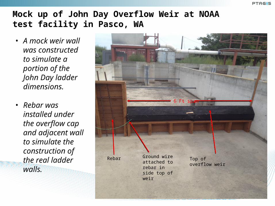
Mock up of John Day Overflow Weir at NOAA test facility in Pasco, WA
6 Ft span
Ground wire attached to rebar in side top of weir
Top of overflow weir
• A mock weir wall was constructed to simulate a portion of the John Day ladder dimensions.
• Rebar was installed under the overflow cap and adjacent wall to simulate the construction of the real ladder walls.
Rebar

Shield Assembly
As shown in the video, the shield is simply saddled over the top of the weir notch then anchored to the weir wall with standard concrete anchors.

Antenna Placement onto Shield
As with the shield, the antenna is designed to simply saddle the shield and anchor to the weir wall with standard concrete anchors.
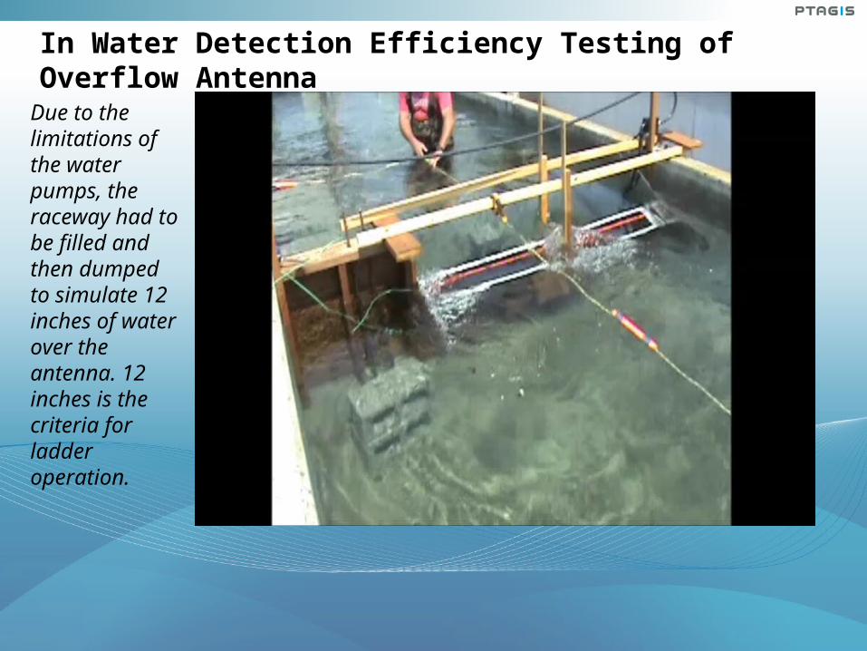
In Water Detection Efficiency Testing of Overflow Antenna
Due to the limitations of the water pumps, the raceway had to be filled and then dumped to simulate 12 inches of water over the antenna. 12 inches is the criteria for ladder operation.

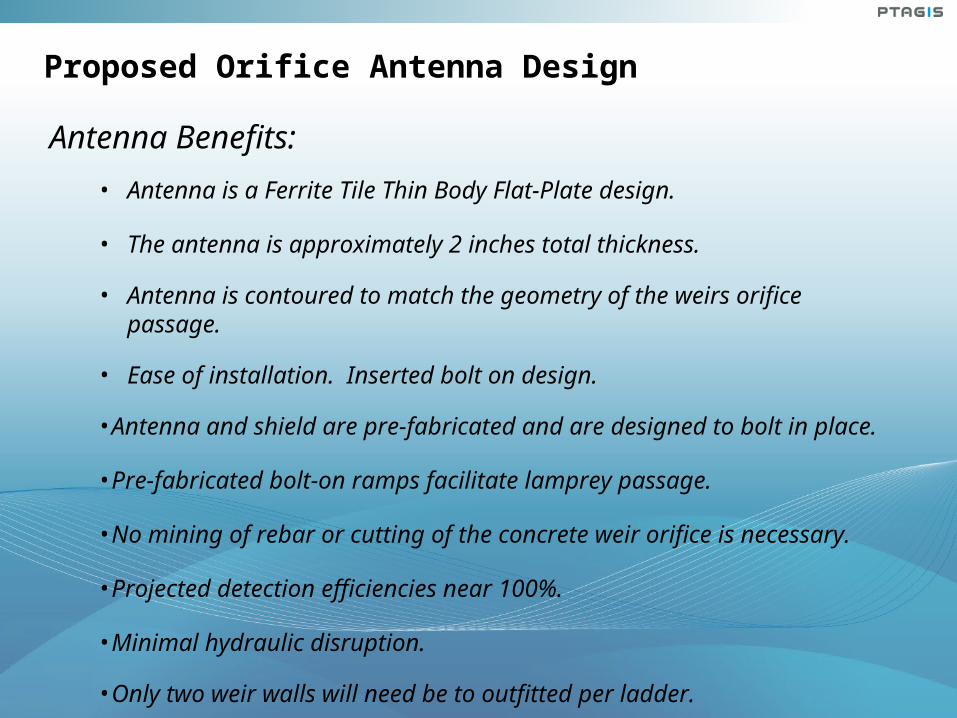
Proposed Orifice Antenna Design
Antenna Benefits:• Antenna is a Ferrite Tile Thin Body Flat-Plate design.
• The antenna is approximately 2 inches total thickness.
• Antenna is contoured to match the geometry of the weirs orifice passage.
• Ease of installation. Inserted bolt on design.
•Antenna and shield are pre-fabricated and are designed to bolt in place.
•Pre-fabricated bolt-on ramps facilitate lamprey passage.
•No mining of rebar or cutting of the concrete weir orifice is necessary.
•Projected detection efficiencies near 100%.
•Minimal hydraulic disruption.
•Only two weir walls will need be to outfitted per ladder.

PIT tag Installation and Equipment Costs for the John Day South Ladder
John Day South Ladder Estimated PIT Tag Bolt-On Antenna Construction Cost
ITEM QUANTITY COST EACH TOTAL
PIT Tag Electronics Room (New 8'x 10' Building)
1 $15,000.00 $15,000.00
Electrical Infrastructure 1 $25,000.00 $25,000.00
Orifice Antennas 4 $10,000.00 $40,000.00
Overflow Antennas 4 $8,000.00 $32,000.00
Contractor to Install Antennas 1 $24,000.00 $24,000.00
TOTAL: $ 136,000.00
Note: Estimate does not include any projected COE engineering support costs.
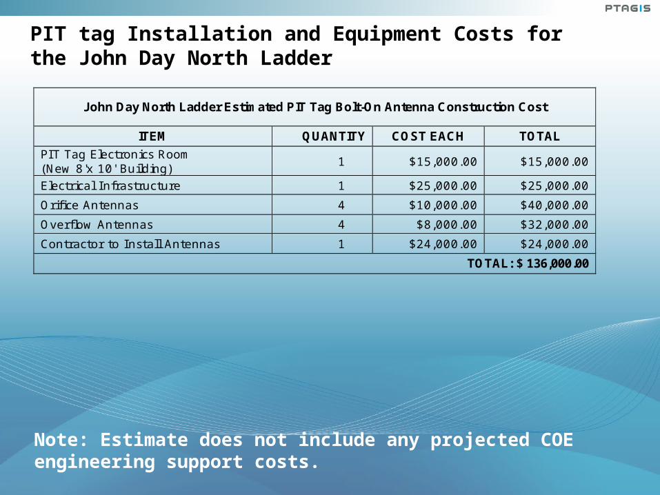
PIT tag Installation and Equipment Costs for the John Day North Ladder
John Day North Ladder Estimated PIT Tag Bolt-On Antenna Construction Cost
ITEM QUANTITY COST EACH TOTAL
PIT Tag Electronics Room (New 8'x 10' Building)
1 $15,000.00 $15,000.00
Electrical Infrastructure 1 $25,000.00 $25,000.00
Orifice Antennas 4 $10,000.00 $40,000.00
Overflow Antennas 4 $8,000.00 $32,000.00
Contractor to Install Antennas 1 $24,000.00 $24,000.00
TOTAL: $ 136,000.00
Note: Estimate does not include any projected COE engineering support costs.

Projected Total Cost of Installation
Combined Costs for Both Ladders
South Ladder with Electronics Installation Provided By PSMFC: $136,000.00
North Ladder with Electronics Installation Provided By PSMFC: $136,000.00
TOTAL: $272,000.00
Possible cost reductions based on several installation factors.
• If space within an existing facility can be allocated for PIT Tag Rooms the cost of purchasing free standing buildings would be eliminated.
• The electrical infrastructure estimate may vary considerably depending on the locations of the PIT Tag Rooms (in relation to the antennas) and the location of available power.
• Depending on the economic feasibility, installation of fiber optic cables from the ladders to the existing Juvenile Fish Facility PIT Tag Room would eliminate the cost of the two additional PIT Tag Rooms.

Questions or Comments?
Gordon Axel 509.547.7518 [email protected]
Scott Livingston 509.735.2773 Ext. 2 [email protected]
Darren Chase 509.735.2773 Ext. 3 [email protected]
Don Warf 509.735.2773 Ext. 1 [email protected]