development of delineator testing standard test
TRANSCRIPT
TTI: 0-6772-1
DEVELOPMENT OF DELINEATOR TESTING STANDARD
Test Report No. 0-6772-1 Cooperative Research Program
in cooperation with the Federal Highway Administration and the
Texas Department of Transportation http://tti.tamu.edu/documents/0-6772-1.pdf
TEXAS A&M TRANSPORTATION INSTITUTE COLLEGE STATION, TEXAS
TEXAS DEPARTMENT OF TRANSPORTATION


Technical Report Documentation Page 1. Report No. FHWA/TX-15/0-6772-1
2. Government Accession No.
3. Recipient's Catalog No.
4. Title and Subtitle DEVELOPMENT OF DELINEATOR TESTING STANDARD
5. Report Date Published: February 2015 6. Performing Organization Code
7. Author(s) Dusty R. Arrington, LuAnn Theiss, Richard A. Zimmer, and Wanda L. Menges
8. Performing Organization Report No. Test Report No. 0-6772-1
9. Performing Organization Name and Address Texas A&M Transportation Institute College Station, Texas 77843-3135
10. Work Unit No. (TRAIS) 11. Contract or Grant No. Project 0-6772
12. Sponsoring Agency Name and Address Texas Department of Transportation Research and Technology Implementation Office 125 E. 11th Street Austin, Texas 78701-2483
13. Type of Report and Period Covered Technical Report: September 2012–August 2014 14. Sponsoring Agency Code
15. Supplementary Notes Project performed in cooperation with the Texas Department of Transportation and the Federal Highway Administration. Project Title: Development of New Delineator Material and Impact Testing Standard to Prevent Premature Failures Specific to Installation Application URL: http://tti.tamu.edu/documents/0-6772-1.pdf 16. Abstract
The objective of this project was to develop a new test method for evaluating the impact performance of delineators for given applications. The researchers focused on developing a test method that was reproducible and attempted to reproduce failure modes witnessed through field observations. The researchers also attempted to optimize the testing standard to minimize the cost and effort to evaluate the products. The researchers feel that the process was successful, and a balanced testing standard meeting all requirements has been developed. 17. Key Words Delineators, Reflectivity, Testing Standards, Crash Testing, Roadside Safety
18. Distribution Statement No restrictions. This document is available to the public through NTIS: National Technical Information Service Alexandria, Virginia http://www.ntis.gov
19. Security Classif. (of this report) Unclassified
20. Security Classif. (of this page) Unclassified
21. No. of Pages 108
22. Price
Form DOT F 1700.7 (8-72) Reproduction of completed page authorized

DEVELOPMENT OF DELINEATOR TESTING STANDARD
by
Dusty R. Arrington Associate Transportation Researcher Texas A&M Transportation Institute
LuAnn Theiss, P.E.
Associate Research Engineer Texas A&M Transportation Institute
Richard A. Zimmer
Senior Research Specialist Texas A&M University
and
Wanda L. Menges Research Specialist
Texas A&M Transportation Institute
Test Report No. 0-6772-1 Project 0-6772
Project Title: Development of New Delineator Material and Impact Testing Standard to Prevent Premature Failures Specific to Installation Application
Performed in cooperation with the Texas Department of Transportation
and the Federal Highway Administration
Published: February 2015
TEXAS A&M TRANSPORTATION INSTITUTE College Station, Texas 77843-3135

TR No. 0-6772-1 vii 2014-10-27
DISCLAIMER
This research was performed in cooperation with the Texas Department of Transportation (TxDOT) and the Federal Highway Administration (FHWA). The contents of this report reflect the views of the authors, who are responsible for the facts and the accuracy of the data presented herein. The contents do not necessarily reflect the official view or policies of the FHWA or TxDOT. This report does not constitute a standard, specification, or regulation.
This report is not intended for construction, bidding, or permit purposes. The researcher in charge of the project was Dusty R. Arrington.
The United States Government and the State of Texas do not endorse products or manufacturers. Trade or manufacturers’ names appear herein solely because they are considered essential to the object of this report.
TTI PROVING GROUND DISCLAIMER
The results of the crash testing reported herein apply only to the article being tested.
_______________________________________ Wanda L. Menges, Research Specialist
Deputy Quality Manager
_______________________________________ Richard A. Zimmer, Senior Research Specialist
Test Facility Manager Quality Manager
Technical Manager
ISO 17025 Laboratory
Testing Certificate # 2821.01
Crash testing performed at: TTI Proving Ground 3100 SH 47, Building 7091 Bryan, TX 77807

TR No. 0-6772-1 viii 2014-10-27
ACKNOWLEDGMENTS
This project was conducted in cooperation with TxDOT and FHWA. The authors thank Darrin Jensen, the project director, and the members of the project panel, which include Michael Chacon, John Gianotti, Johnnie Miller, Robert Ornelas, and Arturo Perez.

TR No. 0-6772-1 ix 2014-10-27
TABLE OF CONTENTS
Page List of Figures ............................................................................................................................... xi List of Tables ............................................................................................................................... xii CHAPTER 1. INTRODUCTION ............................................................................................... 1
1.1 PROBLEM ...................................................................................................................... 1 1.2 BACKGROUND AND SIGNIFICANCE OF WORK................................................... 1
1.2.1 What Are Other States Doing? ............................................................................... 1 1.2.2 Previous Testing Performed at Texas A&M Transportation Institute (TTI) .......... 3 1.2.3 AASTHO National Transportation Product Evaluation Program Temporary Traffic Control Devices Committee ................................................................. 5
1.3 OBJECTIVE ................................................................................................................... 6 1.4 SCOPE OF WORK ......................................................................................................... 6
1.4.1 Task 1: Research to Understand the Problem and Establish Testing Standard Requirements and Constraints ............................................................................. 6 1.4.2 Task 2: Develop Preliminary Testing Standard and Test Vehicle Selection ......... 6 1.4.3 Task 3: Test Vehicle Preparation and Modifications ............................................. 8 1.4.4 Task 4: Perform Full-Scale Impact Testing Following Proposed Testing Procedures ........................................................................................................................... 9 1.4.5 Task 5: Re-evaluation of Testing Standard and Test Vehicle Modifications .................................................................................................................... 10 1.4.6 Task 6: Perform Delineator Impact Testing as Verification of Modifications to Procedures ............................................................................................. 10 1.4.7 Task 7: Prepare and Submit Deliverables ............................................................ 10
CHAPTER 2. RESEARCH TO UNDERSTAND PROBLEM AND ESTABLISH TESTING STANDARD REQUIREMENTS ............................................................................ 11 CHAPTER 3. DEVELOP PRELIMINARY TESTING STANDARD AND TEST VEHICLE SELECTION ............................................................................................................ 15
3.1 EVALUATION OF TASK 1 DATA ............................................................................ 15 3.2 CURRENT TESTING STANDARDS ......................................................................... 16
3.2.1 National Transportation Product Evaluation Programs Temporary Traffic Control Devices ................................................................................................................ 16 3.2.2 Florida High Performance Delineator Criteria (993-2.5) ..................................... 17 3.2.3 AASHTO Manual for Assessing Safety Hardware .............................................. 17
3.3 SELECTION AND PRELIMINARY DESCRIPTIONS OF EVALUATION CATEGORIES ........................................................................................................................ 17
3.3.1 Proposed Testing Procedures and Evaluation Categories ..................................... 17 3.4 SELECTION OF IMPACTING VEHICLES ............................................................... 22
3.4.1 Modified MASH 1100C ........................................................................................ 22 3.4.2 Modified MASH 2270P ......................................................................................... 23 3.4.3 Modified Transit Vehicle (School Bus) ................................................................ 24
3.5 EFFECTS OF TEXAS TEMPERATURES ON DELINEATOR TESTING ............... 24

TR No. 0-6772-1 x 2014-10-27
TABLE OF CONTENTS (CONTINUED)
Page CHAPTER 4. TEST VEHICLE PREPARATION AND MODIFICATION ....................... 29
4.1 MODIFIED 1100C ....................................................................................................... 29 4.2 MODIFIED 2270P ........................................................................................................ 32 4.3 HEAVY TRANSIT VEHICLE..................................................................................... 33
CHAPTER 5. FULL-SCALE IMPACT TESTING FOLLOWING TESTING PROCEDURES ........................................................................................................................... 35
5.1 HIGH SPEED HIGH DURABILITY ........................................................................... 35 5.2 LOW DURABILITY .................................................................................................... 40 5.3 LOW SPEED HIGH ANGLE ....................................................................................... 46 5.4 HEAVY VEHICLE TRAVERSALS ............................................................................ 50 5.5 WITNESSED FAILURE MODES ............................................................................... 54
CHAPTER 6. RE-EVALUATION OF TESTING STANDARD AND TEST VEHICLE MODIFICATIONS.................................................................................................. 57
6.1 EVALUATION OF PREVIOUSLY RECOMMENDED TESTING CATEGORIES ........................................................................................................................ 57 6.2 LIST AND LEAN ......................................................................................................... 58 6.3 EVALUATION OF TEST VEHICLE MODIFICATIONS AND PERFORMANCE ................................................................................................................... 60 6.4 POST DISCOLORATION AND REFLECTIVE SHEETING RETENTION ............. 62 6.5 SUMMARY OF UPDATED TESTING SPECIFICATION ........................................ 65
CHAPTER 7. DELINEATOR IMPACT TESTING AS VERIFICATION OF MODIFICATIONS TO PROCEDURES .................................................................................. 69
7.1 SUMMARY OF TESTING RESULTS FROM TESTING PERFORMED UNDER TASK 6 .................................................................................................................... 69 7.2 ANALYSIS OF TESTING RESULTS FROM TESTING PERFORMED UNDER TASK 6 .................................................................................................................... 73 7.3 IMPACT VEHICLE DAMAGE AND UPDATED VEHICLE MODIFICATIONS ................................................................................................................. 76
CHAPTER 8. SUMMARY AND CONCLUSIONS ................................................................ 81 8.1 IMPACT DURABILITY STANDARD CLASSES ..................................................... 81 8.2 IMPACT CONDITIONS .............................................................................................. 81 8.3 VEHICLE MODIFICATIONS ..................................................................................... 81 8.4 LIST AND LEAN ......................................................................................................... 82 8.4 TESTING FACILITIES................................................................................................ 82 8.5 RECOMMENDED TESTING SPECIFICATION ....................................................... 83
CHAPTER 9. IMPLEMENTATION ....................................................................................... 87 REFERENCES ............................................................................................................................ 89 APPENDIX A. DETAILS OF THE MODIFIED BUMPER SHELL FOR 1100C VEHICLE. ................................................................................................................................... 91 APPENDIX B. ROAD BASE DETAILS ................................................................................. 95
TR No. 0-6772-1 xi 2014-10-27
LIST OF FIGURES
Page Figure 1.1. NTPEP’s Summary Map of State Delineator Testing Requirements. .................... 2 Figure 1.2. Geo Metro (NCHRP Report 350 Test Vehicle) after Approximately 50
Impacts. ................................................................................................................... 4 Figure 1.3. Kia Rio (MASH Test Vehicle) after 100 Impacts. .................................................. 4 Figure 3.1. Average Temperature Comparison. ...................................................................... 26 Figure 3.2. Texas Average Temperature Comparison. ........................................................... 26 Figure 3.3. Climatological Division Chart. ............................................................................. 27 Figure 4.1. Modified 1100C. ................................................................................................... 29 Figure 4.2. Damage to Previous Test Vehicle. ........................................................................ 29 Figure 4.3. Modified 1100C. ................................................................................................... 30 Figure 4.4. Modified Bumper Ground Clearance.................................................................... 32 Figure 4.5. Modified 2270P. ................................................................................................... 33 Figure 4.6. 2270P Vehicle Modifications. .............................................................................. 33 Figure 4.7. Heavy Transit Vehicle. ......................................................................................... 34 Figure 4.8. Heavy Transit Vehicle Modifications. .................................................................. 34 Figure 4.9. Vehicle Ballast. ..................................................................................................... 34 Figure 5.1. 1100C Impact Position before Testing. ................................................................ 36 Figure 5.2. High Durability Test Sample Layout. ................................................................... 36 Figure 5.3. Diagram of Measurement Methods. ..................................................................... 37 Figure 5.4. 1100C after Being Repaired and before Low Durability Testing. ........................ 43 Figure 5.5. Low Durability Test Sample Layout. .................................................................... 44 Figure 5.6. Low Speed High Angle Test Sample Layout. ...................................................... 47 Figure 5.7. Modified Transit Vehicle prior to Impact. ............................................................ 51 Figure 5.8. Heavy Vehicle Traversal Test Sample Layout. .................................................... 52 Figure 6.1. Diagram of Measurement Methods. ..................................................................... 58 Figure 7.1. Bumper Shell Damage Comparison...................................................................... 77 Figure 7.2. Headlamp Damage. ............................................................................................... 77 Figure 7.3. Headlamp Modifications. ...................................................................................... 78 Figure 7.4. Hood Damage. ...................................................................................................... 79 Figure 7.5. Hood Modification. ............................................................................................... 79 Figure 8.1. Diagram of Measurement Methods. ..................................................................... 82

TR No. 0-6772-1 xii 2014-10-27
LIST OF TABLES
Page Table 3.1. Vehicle Specifications per MASH. ....................................................................... 23 Table 4.1. Vehicle Bumper Modifications. ............................................................................ 31 Table 5.1. Test Sample List/Lean and Curvature Offset Summary. ...................................... 38 Table 5.2. Modified Vehicle Impact Damage. ....................................................................... 38 Table 5.3. Post Damage Documentation – Sample Post # 5W. ............................................. 41 Table 5.4. Test Sample List/Lean and Curvature Offset Summary. ...................................... 45 Table 5.5. Modified Vehicle Impact Damage. ....................................................................... 45 Table 5.6. Test Sample List/Lean and Curvature Offset Summary. ...................................... 48 Table 5.7. Vehicle Impact Damage. ....................................................................................... 48 Table 5.8. Test Sample List/Lean and Curvature Offset Summary. ...................................... 53 Table 5.9. Modified Vehicle Impact Damage. ....................................................................... 53 Table 5.10. Witnessed Delineator Failure Modes. ................................................................... 54 Table 5.11. Post Discoloration and Reflective Sheeting Damage. .......................................... 55 Table 6.1. Test Sample List/Lean and Curvature Offset Summary. ...................................... 59 Table 6.2. Modified Vehicle Impact Damage. ....................................................................... 60 Table 6.3. Modified Vehicle Impact Damage (Low Temp Testing). .................................... 62 Table 6.4. Post Discoloration and Reflective Sheeting Damage. .......................................... 63 Table 6.5. Post Damage Documentation – Sample Post # 5W. ............................................. 64 Table 7.1. Test Sample List/Lean Summary for Test No. 467723-1 (Summer 2013). .......... 71 Table 7.2. Test Sample List/Lean Summary for Test No. 467724-1 (January 2014). ........... 71 Table 7.3. Test Sample List/Lean Summary for Test No. 467724-2 (June 2014 –
55 mph). ................................................................................................................ 72 Table 7.4. Test Sample List/Lean Summary for Test No. 467724-3 (June 2014 –
70 mph). ................................................................................................................ 73 Table 7.5. Average Number of Impacts Resisted. ................................................................. 74 Table 7.6. Test Sample Performance Comparison Chart. ...................................................... 75

TR No. 0-6772-1 1 2014-10-27
CHAPTER 1. INTRODUCTION
1.1 PROBLEM
Delineators have become popular across the state of Texas and are being used in several different applications with unique impact conditions and/or impact frequency. Currently, the Texas Department of Transportation (TxDOT) selects products based primarily on cost and only requires that delineators survive up to 10 impacts regardless of application. This testing requirement is effective in preventing some failures; however, it does not adequately evaluate the resilience of delineators used in high-durability impact applications, low speed angled impacts, or heavy vehicle impacts.
These applications have different impact conditions, impact frequency, and durability requirements. Some states such as Florida have moved to a specification that addresses different use conditions. While Florida has maintained the 10-impact standard for normal delineation, they have also instituted a high durability testing requirement (50 impacts) for instances such as lane separation on high-speed roadways. However, the Florida specification does not address the damage due to heavy vehicle traversals and left turn restrictions.
By developing a categorical testing specification, delineator products can be better evaluated for each use application. This enhanced evaluation will lead to the proper selection of the best delineator for a certain application. By pairing delineators with their proper application, one would expect a reduction of delineator failures and therefore a reduction in long-term maintenance costs.
1.2 BACKGROUND AND SIGNIFICANCE OF WORK
1.2.1 What Are Other States Doing?
There is not a federally mandated national standard for testing and evaluating delineators. The Manual on Uniform Traffic Control Devices (MUTCD) sets standards for color and retroreflective sheeting, but does not address testing and evaluation (1). The American Association of State Highway and Transportation Officials (AASHTO) Manual for the Assessment of Safety Hardware (MASH) requires that all delineators are crashworthy (2). There is a national standard developed by the AASHTO National Transportation Product Evaluation Program (NTPEP) Temporary Traffic Control Devices (TTCD) committee, however it is not a federally mandated standard.
For this reason, it is up to each state to either develop personalized evaluation criteria or to
adopt the NTPEP evaluation standard. As shown in Figure 1.1, taken from NTPEP’s TTCD website, many states have simply adopted the NTPEP testing standard (pink states). Many states such as Florida, adopted the NTPEP standard, however they have instituted additional evaluation criteria beyond the standard NTPEP testing standard criteria to fully evaluate the delineator projects. An example of this includes Section 993-2.5.5 of Florida Specification 993 Object Markers and Delineators, also known in the industry as the “High Durability Delineator Specification” (3).

TR No. 0-6772-1 2 2014-10-27
Many states who have additional requirements simply increase the number of impacts and keep the same testing protocol. As manufactures strengthen their designs to resist an increased number of impacts, it is expected that the likelihood of failures in the field would decrease. This method is not necessarily the most efficient solution to the problem. The standard may in fact be driving up the cost of delineators without actually addressing failures in the field. These testing standards may result in a delineator design that will perform well in a test, but may perform poorly in the field. An example of this may be a result of using the wrong test vehicle (different test vehicles result in different impact delineator performance). Some states, shown in red, have developed their own independent specifications, which can be less stringent than the NTPEP impact standard.
Figure 1.1. NTPEP’s Summary Map of State Delineator Testing Requirements.
A national scientific-based standard for testing delineators is needed. This standard should
be formulated to address failure modes witnessed in the field and should have a different testing specification for each specific application. For example, roadside delineators and object markers are subjected to different impacts than delineators used for high speed lane separation. The goal of this research was to develop a set of testing standards for different applications. The standard would be similar in format to ASTM testing standards and could serve as national standard for the evaluation of delineators in different applications.

TR No. 0-6772-1 3 2014-10-27
1.2.2 Previous Testing Performed at Texas A&M Transportation Institute (TTI)
The TTI Proving Ground at Texas A&M University’s Riverside Campus has performed multiple delineator impact tests for multiple manufacturers according to multiple impact testing standards. Some of the standard tests performed include:
• Florida high durability delineator testing standard (50 impacts at high temp with 48-inch
tall delineator).
• National Cooperative Highway Research Program (NCHRP) Report 350 (4).
• AASHTO MASH compliance testing of delineators mounted on curb systems.
• manufacturer-stipulated 100 impact durability tests.
• NTPEP standard 10 impact tests.
At the TTI Proving Ground, tested delineators ranged in height from 18 inches to 48 inches.
TTI’s facility has tested all of the following installation methods: butyl pads, epoxy, concrete anchors, concrete embedded anchors, soil anchors, and soil direct driven delineators. The TTI Proving Ground has tested products with various features, such as quick release pins and internal mechanical devices that right the delineator after impact.
The TTI Proving Ground is one of only a few facilities in the nation that has performed the
new Florida high durability testing standard and other durability tests with total number of impacts in excess of 100 impacts. From this testing, TTI researchers have gained a great deal of knowledge about the damage these delineators do to a test vehicle. The researchers found that after 20–30 impacts delineators over 36 inches begin to beat the hood of the vehicle into the engine compartment. Researchers at TTI have witnessed hoods so severely deformed that the delineators have contacted vital engine compartment components. This contact caused major mechanical problems that the onsite mechanical department was able to address in most cases. Sometimes, however, the vehicles were damaged beyond repair.
Over the years, TTI researchers have learned how the vehicle becomes damaged and have
been able to compensate to an extent. As an example, Figures 1.2 and 1.3 show the resulting damage to two different test vehicles after being impacted 50+ times. The vehicle in Figure 1.2 was from one of the first attempts at running the Florida high durability testing standard. That vehicle was damaged beyond repair and would not have been able to finish the testing; however, it did outlast the product being tested. The test vehicle shown in Figure 1.3 was from the latest set of tests, where the vehicle impacted a set of delineators 100 times.
Notice the significant difference in the damage between Figure 1.2 and Figure 1.3. Some of the reduced damage is due to a difference in delineator design, some is due to a difference in the vehicle design, and finally some is due to the proposed modifications to the testing procedure. This vehicle could be used in future testing with some minor modifications; however, there is some damage to the vehicle that changed the profile of the vehicle and therefore the impact characteristics of the vehicle. TTI researchers believe that the use of technology used in the racing industry, such

TR No. 0-6772-1 4 2014-10-27
as flexible body supports with rigid backup structures, would better maintain the front profile of the vehicle without sacrificing flexibility of the body paneling. By supporting the body panels in a flexible manner, the profile of the vehicle will be maintained without making the vehicle overly stiff, which could lead to a disproportionate number of failed delineators during testing.
Figure 1.2. Geo Metro (NCHRP Report 350 Test Vehicle) after Approximately 50 Impacts.
Figure 1.3. Kia Rio (MASH Test Vehicle) after 100 Impacts.

TR No. 0-6772-1 5 2014-10-27
Due to the TTI researchers’ business relationships with the manufacturing industry through crash testing, the researchers were invited to give a presentation at one of NTPEP’s meetings in San Antonio. The presentation provided background on how testing labs are coping with the extreme damage to test vehicles while performing new high durability (50+) delineator crash testing. The presentation was in response to NTPEP’s attempt to develop a national high durability delineator testing standard.
1.2.3 AASTHO National Transportation Product Evaluation Program Temporary Traffic Control Devices Committee
The NTPEP TTCD committee is composed of multiple state Department of Transportation (DOT) representatives. With insight from manufacturers that join in on many of the committee meetings, they collectively develop national testing standards for delineators and other temporary traffic control devices. When it comes to delineators, NTPEP has a single standard where ten (36-inch surface mounted or 48−inch soil embedded) delineators are installed such that five will be traversed by a non-standardized vehicle tire and the remaining five will impact the vehicle bumper near the centerline of the vehicle. Half (five) of the impacts are performed at a temperature of 32°F plus or minus 5°F. The other five impacts are at an ambient temperature of 85°F plus or minus 5°F. Certain data are measured and recorded after each impact, documented, and eventually placed in a report. This standard is a very good starting point; however, it is typically performed with different (non-standard) vehicles at a non-accredited test facility. Some researchers believe that this standard could be improved by using standard vehicles and more scientifically accepted approaches to measuring some of the recorded evaluation criteria.
Recently, NTPEP attempted to develop a high durability testing standard based on Florida’s
specification. In the initial testing, the front of the test vehicle was coated with a semi-rigid plastic to protect the vehicle from damage during the testing. Their facility does not have mechanics available to perform repairs on the vehicle in the event of a mechanical malfunction of the impact vehicle. Several different manufacturers submitted samples to NTPEP for testing. The results of the testing were astonishing. Many of the test samples failed after the first impact. Many believe the reason for the failures was caused by the properties of the modified vehicle. First, the plastic coating may have increased the friction between the vehicle and the test samples, possibly causing failures at the base. The second cause was due to the plastic being carried down near the ground creating a rigid air dam only inches off the ground. This rigid air dam created a profile not found in the standard vehicle fleet and may have caused an impact condition more extreme than should be reasonably expected in the vehicle fleet.
Due to the shortcomings of the vehicle modifications and the fact that NTPEP and many of
the states do not allow testing at third party testing sites such as the TTI Proving Ground, many of the manufacturers joined together in protest of the developing standard. Currently, the group is considering using a surrogate vehicle or a standardized stock/modified vehicle. The group is also debating the issue of allowing manufacturers to test at accredited third party testing facilities such as the TTI Proving Ground.
Many of the manufacturers are pushing to allow testing at third party testing facilities due to
time constraints. Third party testing facilities are much more expensive, however, manufacturers state that they can get a report in as little as three months from the time a contract is signed to

TR No. 0-6772-1 6 2014-10-27
perform testing. Manufacturers stated that it can take more than twelve months to get a report from the NTPEP testing facility. Manufacturers also stated that the lost revenue while waiting for reports is generally significant enough to offset the added cost of testing at third party testing facilities.
1.3 OBJECTIVE
The result of this research project is a complete impact testing standard for the evaluation of delineators for use on TxDOT highways. This testing standard provides an evaluation of the delineators based on the intended installation applications.
1.4 SCOPE OF WORK
1.4.1 Task 1: Research to Understand the Problem and Establish Testing Standard Requirements and Constraints
TTI researchers met with the project director and project advisory panel to review the expectations of the project and establish a firm direction for the proposed research. One of the objectives of the meeting was to establish expectations of the new design standard. This meeting also served as the first chance to discuss what problems TxDOT is currently experiencing with delineators. From this list of problems, TTI researchers generated a list of district locations to visit to discuss the problems in further detail.
TTI researchers then traveled to districts with known problems to inspect delineator
installations. They also scheduled meetings with district engineers and maintenance personnel to get further information on what failures were occurring in the field in an attempt to determine what may be causing them. This information was crucial in the development of the new standard to guarantee that failures in the field were being reproduced in the testing sequence. Researchers asked for samples of failed delineators for further analysis to determine the cause of the failures.
TTI researchers also contacted other states, such as Florida, who are currently
experiencing similar problems in an attempt to determine what they are doing to address the problem. Next, TTI researchers reviewed previous research dealing with delineator failures and placement applications for further insight. Researchers also reviewed previous delineator component testing that was available. Researchers contacted manufacturers to determine what problems they may have experienced with their products. Finally, the researchers contacted AASHTO NTPEP Temporary Traffic Control Devices Technical Committee to discuss what progress they have made toward the development of their new high durability testing standard.
1.4.2 Task 2: Develop Preliminary Testing Standard and Test Vehicle Selection
Researchers analyzed the information gathered in Task 1. From this information, the researchers began to categorize delineator usage into multiple generic applications. The researchers then evaluated each application to determine if any of the applications could be combined to reduce the overall complexity of the testing standard. Once a list of applications was generated, each application was evaluated to determine the primary cause of failures in each application. Once a list of primary causes of failures was formulated, the researchers then
TR No. 0-6772-1 7 2014-10-27
designed a test sequence for each application in an attempt to reproduce known failure modes seen in the field.
As part of this development process, the researchers looked at impact vehicle type,
installation method, ability of the delineator to right itself, permanent list and lean, impact angle, temperature effects, reflective sheeting retention and degradation, and methods for documentation of testing. This list was not exclusive. If other forms of evaluation become pertinent, these may be added to the list of criteria.
As for the test vehicle, the researchers completed an evaluation of the vehicle fleet to
determine what vehicle class (not specific vehicle) constitutes a reasonable worst case for each application. A vehicle class was chosen by its availability and its ability to reproduce failures seen in the field. This mirrors the basic methodology of other testing standards such as AASHTO MASH. An attempt was made to standardize using a vehicle class similar to those used by other testing standards. This would reduce the cost of testing by using vehicles that may already be stocked by testing labs. A secondary selection criterion dealt with the vehicles ability to complete the prescribed testing.
As part of the development of the standard, some time was spent developing reasonable
limits on the evaluation criterion. For instance, the researchers suggested upper limits on acceptable list and lean values. This may be based on driver perception or on the lab’s precision when measuring the criterion.
Since the impact performance of the current delineator products being produced can be
dependent on ambient temperature, the researchers evaluated temperature ranges at which the products may need to be tested. Researchers made recommendations based on historical temperature data. The temperature ranges are also influenced by the ability of testing labs to produce and test within the temperature ranges.
Once all criteria for each application were established, a preliminary testing standard was
generated. This was a full procedure similar in format to current American Society for Testing and Materials (ASTM) testing specifications. Once finalized, the preliminary testing standards were submitted to the project director and project advisory panel for review. The researchers then met with the project panel to discuss and modify the testing procedure before proceeding to Task 3.
Preliminary observations showed there were four possible applications that may require independent evaluations.
1. Low Durability – This would include roadside delineation and self-righting object markers.
2. High Durability – This would include lane separation of high speed travel lanes, including high occupancy vehicle (HOV) and tollways.
3. Heavy Vehicle Traversal – This would include lane separations and turn restrictions where there is an elevated risk of heavy vehicle traversals.
TR No. 0-6772-1 8 2014-10-27
4. Low Speed, High Angle Traversals – This would include urban left turn restrictions where there is an elevated risk of the delineators being traversed at angles greater than 25° from the longitudinal axis of the delineator installation.
1.4.3 Task 3: Test Vehicle Preparation and Modifications
Upon approval of the preliminarily testing procedure, the TTI Proving Ground located suitable test vehicles meeting the stipulated vehicle class requirements from Task 2. It was expected that as many as three vehicle classes would need to be procured for the testing under this project.
The preliminary expectation was that the following vehicle classes needed to be procured
as part of this process. The first was a small passenger car class. This class has been historically thought to be a worst case impact condition. This is due to the delineators wrapping around the bumper, causing them to cling to the hood upon impact, thereby putting high stresses on the delineator base and installation method.
The second class was a heavy vehicle class. This class included transit buses, heavy
goods vehicle, soil haulers, or even tractor trailers. These vehicles generally have high axle loads and turn across delineator installations at low speeds. The heavy axle loads and twisting action of turning across the delineators induce failures not previously seen in standard impact testing but witnessed in field installations. An evaluation of installation applications needed to be performed as part of Task 2 to determine which vehicle class would best represent the failures witnessed in the field.
Finally, a light truck vehicle class was thought to be needed to evaluate its interaction
with the delineators. Generally, light trucks have been thought to not cause significant damage to delineators in the past; however, as the vehicle fleet has evolved these vehicles have become larger and heavier. This may cause two different outcomes. First, because they are heavier they may be damaging bases or some of the mechanical devices within the delineators. Second, these larger trucks are less likely to be damaged by delineator impacts during traversals leading to an increase number of traversals over the intended life of a delineator installation. This problem is compounded by the advent of oversized and stiffened front and rear bumpers known as “Brush Guards.” These aftermarket upgrades almost completely mitigate any damage to the traversing vehicle. This removes any deterrent for the driver to avoid traversing the delineator installation. This has led, in some cases, to an increased number of impacts during the life of the delineator installation. For this reason, field evaluations may require the testing of delineator installations with this class of vehicle to determine impact performance.
Each class of vehicle was then evaluated to determine if any modifications needed to be
performed on the vehicle. Modifications would be required if it was believed that the vehicle would not be able to complete the testing sequence.
This testing is violent for both the test vehicle and test driver. Each individual delineator
impact generally caused only slight damage to the impacting vehicle, sometimes similar to a large hail impact. However, after 60+ individual impacts, the damage becomes compounded and

TR No. 0-6772-1 9 2014-10-27
can cause significant damage to the impacting vehicle. This damage not only puts the vehicle at risk, but it also begins to change the profile of the vehicle between impacts. During durability impact testing sequences (20+ traversals), the vehicle generally has a very different profile at the end of testing when compared to when the testing started.
For these reasons, the vehicle required modification to prevent excessive damage. This
modification accomplished two things. First, it protected the vital vehicle components from damage allowing the vehicle to complete the testing sequence. Second, it helped to prevent excessive profile changes during the testing. The modifications provided a more consistent test throughout all of the impacts. All modifications were completed in such a way that they would not adversely affect the performance of the delineator. Any modification to parts, such as the bumper and hood or other body panels, only served to support them from excessive damage. If panels are stiffened excessively, it can be detrimental to the impact performance of some delineators. For this reason, modifications were designed to give but also be supportive. A great example of this methodology is the racing industry. In the racing industry light and flexible panels are supported by stronger support structures that make up the frame and body of the vehicle.
During the process of modifying the vehicles, the TxDOT representatives were given
oversight and were given the chance to veto modification methods that they felt were not reasonable or acceptable. Upon completion of the modifications, a list of modifications and modification methodology was generated and submitted to TxDOT for approval before proceeding with crash testing. This methodology was written such that a future testing lab technician could use them as a guide in modifying future vehicle models.
1.4.4 Task 4: Perform Full-Scale Impact Testing Following Proposed Testing Procedures
Upon approval of the testing procedures (Task 2) and vehicle modifications (Task 3), manufacturers were contacted to obtain test samples to evaluate the validity of the testing procedure. Full-scale crash tests for each proposed application was performed to evaluate the testing procedure to determine if modifications needed to be made to either testing procedure or the test vehicle. The tests were performed at TTI’s Proving Ground located at the Texas A&M University Riverside Campus using available equipment and facilities. Due to low ambient temperature requirements for cold weather testing, some of the testing was performed at night to take advantage of naturally colder temperatures. Due to extreme temperature variances that may be required during testing, some tests were performed in two phases, separated by up to 6 months (winter and summer tests).
To obtain products for validation of testing protocols, manufacturers were contacted and asked if they would be willing to submit products for evaluation during the development of the new standard. All contacted manufacturers were given a preliminary copy of the testing procedure from Task 2 before proceeding with impact testing. The researchers attempted to contact all known manufacturers of delineator products to give each a reasonable chance to submit their products for preliminary evaluation. Any evaluation and testing performed under this research project is for evaluation of the testing standard and will not be sufficient to evaluate

TR No. 0-6772-1 10 2014-10-27
any specific product performance under the new standard. Of the manufacturers contacted only three manufacturers were willing to donate samples for testing.
The exact number and types of tests to be performed to verify the validity of the
procedure was determined based on the results of Tasks 1–3, analysis, engineering judgment, and interaction with the project advisory panel. The most discerning tests were performed first.
Multiple days of full-scale impact tests were budgeted for the proposed project. The testing was performed in accordance with the guidelines and procedures set forth in the proposed testing procedure. Care was taken to provide safety for the driver, support crew, and observers of the testing.
The results of the testing were summarized and sent to TxDOT for review. The researchers then met with TxDOT representatives to discuss the results and any problems that arose during the testing. 1.4.5 Task 5: Re-evaluation of Testing Standard and Test Vehicle Modifications
During this stage of the project, the TTI researchers evaluated the results of the preliminary testing. The researchers addressed any problems with the testing procedure or with the vehicle modifications that became evident during the preliminary testing. The researchers also addressed the question, “Did the proposed test procedure address the failures witnessed in the field?” Once all modifications were finalized, and researchers submitted an updated procedure to TxDOT for review and approval. This task was accomplished in parallel with Task 6 as some delineator testing application standards were addressed independently. 1.4.6 Task 6: Perform Delineator Impact Testing as Verification of Modifications to
Procedures
During this stage of the project, the TTI researchers performed testing on select samples of delineators. At this stage, the testing was performed as if the manufacturers had submitted the material for testing and approval. This provided information on the robustness of the standard and its ease to perform. This also served as verification that the modifications performed under Task 5 were successful. Again, the tests were performed at TTI’s Proving Ground located at the Texas A&M University Riverside Campus using available equipment and facilities. Due to low ambient temperature requirements, some of the testing was performed at night to take advantage of naturally colder temperatures. 1.4.7 Task 7: Prepare and Submit Deliverables
Details of the research performed in each year of this two-year project is documented in this research report, prepared, and submitted to TxDOT following department guidelines. A formalized testing procedure, including tests suggested and vehicle modification methodology, was prepared and submitted to TxDOT as part of the report.
TR No. 0-6772-1 11 2014-10-27
CHAPTER 2. RESEARCH TO UNDERSTAND PROBLEM AND ESTABLISH TESTING STANDARD REQUIREMENTS
At the project kickoff meeting, TTI researchers gave a presentation describing the proposed course of action for the project. The project panel concurred with the objectives described in the presentation and asked TTI to continue with the research as planned.
Over the next few months, TTI researchers sent out requests to maintenance groups in the four major metropolitan areas (Dallas/Fort Worth, Houston, Austin, and San Antonio). Only Houston and San Antonio metropolitan areas responded to the researchers’ requests. Many of the replies stated that they only utilized delineators in side-of-road applications as object markers. The primary complaint with this type of installation was that mowers frequently damaged the delineators. The ones that did indicate utilization of delineators for near-roadway applications indicated they were not seeing high numbers of failures, with the possible exceptions of near gore points in front of crash cushions. These reduced numbers of failures are likely due to increased offset distances from the roadway, a common practice in the responding areas, as indicated in TxDOT Report Number FHWA/TX-12/0-6643-1 (5). The gore areas are the exception as vehicles are repeatedly leaving the roadway and striking the delineators in these areas.
Currently, there is no standard for testing for mower impacts with delineators due to the severity of these incidents. It is also unlikely that a standard could be developed to make general polymer delineators resist the impact without severe damage being induced to either the delineator or the mower.
TTI researchers did not receive any responses from the Dallas/Fort Worth metro area; specifically the crews in charge of US 75 where the majority of failures have been noticed. In this particular installation, the delineators are being utilized as lane dividers to separate HOV lanes from normal travel lanes, with little to no offset distance from travel lanes. This limited offset distance leads to a more frequent impact occurrence rate. Since these roadways are limited on space, increasing offset distance between delineators and travel lanes to reduce the frequency of impacts is not feasible. The delineators would need to be designed to resist more impacts without failure to reduce their frequency of repair.
Currently, due to the elevated impact occurrence rate, there are sections of US 75, and other roadways, that cannot be repaired as frequently as delineators are failing, leading to sections where the roadway is void of delineators. Increasing the durability of the delineators should reduce the number of failures and allow the maintenance crews to keep up with repairs. This should increase safety by ensuring the installations are providing a proper barrier to separate traffic and by reducing exposure of maintenance crews to traffic by reducing the frequency of repairs.
TTI researchers have witnessed multiple failure modes in durability testing of delineators that should be addressed. Many of these failure modes have been witnessed across Texas, including the US 75 installation. Many of these failure modes were later witnessed in testing performed under this project.
TR No. 0-6772-1 12 2014-10-27
The first common failure mode is failure of the surface mounting method. This is a
failure of the material fastening the base of the delineators to the roadway. Most failures of this type have been attributed to the failure of a specific type of concrete anchor bolt. TTI researchers have witnessed this anchor bolt pulling out of the concrete test deck over a several-year period while testing different manufacturers’ delineator products. All manufacturers who come to TTI for testing have selected this particular brand of anchor bolt due to the relatively inexpensive cost of the product. For this reason, TTI researchers cannot definitively attribute the pullout failures to one anchor bolt manufacturer. This particular problem may be attributed to the fastening method itself, since most, if not all, of these anchors bolts are designed to carry static loads as opposed to the dynamic loads seen during vehicle impacts. These failures show the importance of the bolt itself in durability of the delineators. Another failure specific to mechanical anchorage includes the failure of the polymer base at the fastening location. This releases the base but leaves the anchor bolt in the roadway surface.
Next, in the limited experience with other surface mounting techniques, TTI researchers have witnessed that epoxies and other polymer glues are highly susceptible to roadway and delineator base surface conditions at the time of application, such as: temperature, cleanliness, and texture, to name a few. The bond is also susceptible to the chemical makeup of the delineator base itself. Finally, freeze/thaw cycles are a considerable issue in some climates. Water can collect between the base and roadway surface where it then freezes during cold weather. As the water swells while freezing, it pries the delineator base away from the roadway surface, breaking the bond.
Another failure mode frequently witnessed while testing delineators is a failure of the method for connecting the base to the delineator itself. This is generally the key feature that sets one delineator product apart from another competing product and is generally the patented portion of the product. These connections are designed to be quickly detachable to speed up maintenance and installation; however, by doing so, it creates a weak point were the delineator may fail when struck by an impacting vehicle. This method of attachment varies dramatically. A few examples include the passing of a retention pin through the base and the delineator to more complex connections that use a twist locking mechanism to secure the base. These quick release mechanisms generally result in stress risers that either fracture or tear the material around the connection location. This results in either a complete or partial failure of the connection, leaving the delineator leaning significantly.
The next most common failure mode is a failure of the delineator post itself. In some cases, generally with fiber composite materials, the delineator itself will fracture under impact load. This is usually the result of a brittle material being used to manufacture the delineator post, which is sometimes exaggerated by colder ambient temperatures. Some delineator designs develop a crease just above the base that prevents the delineator from returning to vertical. As this drastically reduces the effectiveness of the delineator, many manufacturers have developed methods of mechanically restoring the delineator to a vertical position; however, these mechanical connections introduce new failure modes. Some vertical cracking has been noticed during testing, usually in round tubular posts that get flattened during testing. This does not usually result in failure, but it does affect the aesthetics of the installation. Finally, many of the

TR No. 0-6772-1 13 2014-10-27
polymer delineator posts begin to curl during testing. This is often a function of the material used. As the delineator is struck multiple times, the material on the front face of the post begins to stretch, causing the delineator to list or lean. This generally does not result in a failure but does begin to diminish the aesthetics of the delineator over time.
Finally, while many delineators successfully resist a large number of impacts. they may either lose their reflective sheeting or become covered in black plastic and rubber from the impacting vehicles. This dramatically reduces the delineator’s aesthetic properties, and it can significantly reduce its nighttime visibility. As the delineator becomes less visible, it performs less of its intended purpose at night. For this reason, more emphasis in the future should be placed on designing delineators to retain their reflective sheeting and evaluating a delineator’s ability to retain the sheeting.
In future development, a balance will need to be struck between durability and cost. Products can be produced to last almost indefinitely, requiring little to no maintenance but would likely be too costly to install. On the other hand, very cheap products can be produced that may not even survive one impact, which in some applications could lead to very high maintenance costs. Currently, when a TxDOT project is bid, there is no categorization to separate the more durable delineators from the lower cost disposable delineators. For this reason, the higher cost delineators must compete against the lower cost delineators in all applications. This generally results in a cheaper disposable delineator being installed in a high durability application for which its designers never intended it to be used. This in turn results in increased maintenance costs. Testing categories would serve to verify that the proper delineator would be selected for the appropriate application.
As part of the background research process, a request for participation and input was submitted to many of the U.S. manufacturers of delineators. A similar request was submitted to NTPEP TTCD committee to gain input. Those that responded stated that they would be willing to help in whatever way possible. Three manufacturers were willing to submit of products for testing. TTI researchers have been informed that NTPEP is no longer pursuing a high durability testing standard due to the severe damage it inflicts on the vehicle. They have suggested continuing to perform testing at testing labs, such as the TTI Proving Ground, until a national standard is developed. TTI researchers have reviewed comments from the recipients on the proposed testing and have also contacted other states, such as Florida, for comments with reasonable success.


TR No. 0-6772-1 15 2014-10-27
CHAPTER 3. DEVELOP PRELIMINARY TESTING STANDARD AND TEST VEHICLE SELECTION
Under this task, the TTI researchers attempted to set a preliminary testing procedure for the durability testing of delineators. As part of this task, the researchers suggested different evaluation categories to better represent specific installation application requirements. The researchers also went through a process of selecting impact vehicles to be used for each evaluation category.
3.1 EVALUATION OF TASK 1 DATA
The responses from Task 1 were limited; however, the previous testing knowledge and review of other testing standards have given the TTI researchers an in-depth understanding of the problem. The failures in the field can be consolidated into four different installation types.
The first type is a low-durability, off-road object marker. This includes all polymer delineators placed with significant offset distance from the roadway to significantly reduce the likelihood of being impacted. These delineators are only rarely impacted making their ability to resist a high number of impacts of less concern. Since these delineators are offset significantly from the travel lane and are generally used to mark an obstacle, visibility of this delineator should be a top priority. By maintaining a high visibility, the delineator should also help prevent the highest risk to these installations (mower impacts). This category should be focused on providing a minimum reasonable durability while minimizing cost and maximizing visibility.
The second type includes a low-speed turn restriction. These installations are surface mounted on the roadway or they are placed on a plastic or concrete curb divider. These installations are generally placed in urban environments to delineate a concrete curb or as a retrofit to an undivided urban street to prevent left turns. These retrofit installations are a common, relatively inexpensive method of reducing accidents by controlling access to city streets. Many drivers understand that low speed delineator impacts will not cause significant damage to their vehicles, so they proceed to drive over the installations. These drive-overs cause the delineators to be impacted in an orientation that was not intended. Due to the severe forces absorbed by the delineator during a moderate to high-speed impact event, many manufacturers have opted to incorporate geometries and mechanisms to help resist the impact forces. The problem is that many of these features are directional in nature. So, many of these delineators may fail prematurely because they are being impacted in an orientation other than what they were designed for. Another issue is that since there is generally only minor damage to the impacting vehicle, it leads to repeat offenders, which increases the impact frequency. This category should focus on high durability when impacted at low speeds and high angles by a moderate weight vehicle.
The third installation type includes lane dividers in urban areas with moderate speeds and significant heavy vehicle traffic. In many urban areas, such as Houston, delineators are used to separate traffic, to delineate bike lanes, or delineate a travel path. In some cases, these installations are placed in such a way that heavy vehicle traffic regularly traverses the installation. This may be caused by insufficient offset distance for the heavy vehicle to make a

TR No. 0-6772-1 16 2014-10-27
traffic maneuver, or it may be caused by poor vehicle operator skills. In any case, this leads to a significant increase in low-speed heavy vehicle impacts. In the United States, the axle weights are limited to 20,000 lb. This weight is significantly higher than the current test vehicles being used. As many delineator designs use a mechanical device for connecting the delineator to the base to help right a delineator after an impact, there is a significant risk of the device being damaged after repeated heavy vehicle traversals. Associated categories should focus on repeated low-speed traversals by heavy vehicles while turning to apply a twisting action to the base.
The final type includes lane dividers for high-speed roadways with moderate to no offset distance from the travel lane. These installations are generally placed in high-volume and high-speed locations. The delineators are generally used to separate traffic lanes flowing in the same direction. Many times these delineators are used to separate HOV managed lanes from normal traffic lanes. This leads to an increased risk of a high number of high-speed impacts. There are some indications that many of these impacts are caused by single occupant vehicles going into and out of HOV lanes in an attempt to reduce travel times and avoiding detection. Previous TTI reports indicate that many of the impacts are due to small sedan and light truck impacts. Many of these impacts are caused by inattentive drivers drifting out of the travel lanes. Since there is little to no offset distance, a vehicle making only a slight deviation from the travel lane may impact the delineator installation. Associated evaluation categories should focus on a high number of impacts at a high impact velocity. As many of these installations are placed at very low offset distances, the testing should focus on retaining the delineators’ initial visibility in an attempt to reduce impacts and to better fulfill the delineators intended purpose.
These generic types of installations are not mutually exclusive. One real world application may have characteristics of more than one type listed above. For this reason, the testing criteria should not be mutually exclusive. The evaluation categories should address specific failure characteristics of a delineator. It will then be up to the maintenance crew or design engineer to select the correct minimum list of qualifications for the specific application.
3.2 CURRENT TESTING STANDARDS
3.2.1 National Transportation Product Evaluation Programs Temporary Traffic Control Devices
The only current national testing standard is the one developed by AASHTO NTPEP TTCD. A full list of requirements can be found in the TTCD’s “Project Work Plan for Laboratory Testing and Field Evaluation of Traffic Control Devices” (6). To summarize the testing specification, 10 delineators are submitted by a manufacturer for testing. Eight 36-inch delineators are installed in two parallel lines where half of the delineators are struck by the bumper near the center of the vehicle and the other half of the delineators are set to be overridden by the vehicle tire. Half of the bumper and tire impacts are oriented in the direction of the vehicle travel path, and the other half are rotated 25° clockwise from the path of the vehicle. A total of 10 impacts are performed. Five impacts are at an ambient temperature of 27–37°F. The remaining five impacts are performed at a temperature of 80–90°F. The same installation is utilized for all 10 impacts. The following data are recorded after each impact: list/lean; any cracks, splits, or breaks; percent retained reflective surfaces; any bonding failure; and problems

TR No. 0-6772-1 17 2014-10-27
associated with testing. All testing is performed at a speed of 53–57 mph. There is no indication as to how each of the criteria was selected for this testing. This standard does not specify a standard test vehicle class.
3.2.2 Florida High Performance Delineator Criteria (993-2.5)
The Florida standard is based upon the NTPEP TTCD standard. Florida has made a few changes to evaluate the long-term durability of delineators after repeated impacts. First, the number of impacts was increased from 10 to 50. Florida also removed the requirement for low temperature testing due to its warmer climate. All testing is performed at a temperature of 65°F or greater. The height of the delineator has been increased to 48 inches, making the testing significantly harder to pass. The delineator is also required to be mechanically anchored. Finally, a failure criterion was added in the specification. The specification requires that all delineators return to within 5° of vertical or it is considered a failure, with the exception that two may list between 5° and 10°. No post failures are allowed.
3.2.3 AASHTO Manual for Assessing Safety Hardware
MASH considers delineators as self-qualifying products with the exception of when they are attached to a molded polymer curb. The NTPEP or equivalent vehicle impact testing serves as a qualifying test in most cases, and therefore testing of these products is generally not addressed in MASH.
3.3 SELECTION AND PRELIMINARY DESCRIPTIONS OF EVALUATION CATEGORIES
3.3.1 Proposed Testing Procedures and Evaluation Categories
3.3.1.1 Low Durability (High or Low Temperature)
This testing is built on the successful testing standard developed by the NTPEP TTCD committee. Below is a list of requirements for this standard of testing. Some of the changes are to bring the standard in line with the current MASH standard for uniformity. This testing is specifically oriented toward the testing and evaluation of delineators with significant offset from travel lanes limiting the impact frequency rate. This evaluation focuses on impacts from a small sedan. The small sedan is recommended as a worst case due to the following design characteristics: low ground clearance, low hood height, and round bumper profile. Previous testing experience has shown that these characteristics result in a higher pullout force being applied to the base and base to delineator connection. This higher pullout force is a result of the delineator wrapping around the front of the vehicle, resulting in high friction forces between the impacting vehicle and delineator as the base attempts to pull the delineator under the impacting vehicle.
1. Generic Test Specifications. a. Impact Vehicle: Modified MASH 1100C (small sedan). b. Impact Velocity: 62 mph.

TR No. 0-6772-1 18 2014-10-27
c. Total Number of Test Samples: 16 delineator posts and 8 bases (8 hot and 8 cold).
d. Hot Test Temp: 82°F or greater. e. Cold Test Temp: 35°F or lower. f. Manufacturer-suggested maximum installed height of delineator shall be tested.
2. Test Installation. a. Two rows of four delineators. b. One row will be aligned with vehicle tire (wheel over impact). c. One row will be aligned with the opposing vehicle quarter point (bumper impact). d. Each delineator will be spaced 50 inches (or 2 inches greater than delineator
height) from a subsequent delineator to prevent interaction. e. Half of the bumper and wheel over impacts will be oriented parallel to the path of
the impacting vehicle. f. Half of the bumper and wheel over impacts will be oriented 25° from the path of
the impacting vehicle. 3. Surface Attachment Method.
a. All testing will be performed with the intended product (no substitutions). b. Material/technical specifications must be submitted with each product. c. At least two delineators must be attached with each type of proposed attachment
method. i. At least one of each method must be a bumper impact.
ii. At least one of each method must be a wheel over impact. iii. An equal number of bumper and wheel over impacts will be performed on
each method. d. If more than four attachment methods are proposed.
i. Number of samples tested at one time can be increased to either 10 or 12 at the testing facility’s discretion.
ii. Testing can be repeated with a new set of delineator samples. iii. Testing lab can evaluate methods for equivalency and/orworst case using
either small or large scale dynamic impact loading. 4. Documentation.
a. Material classification data shall be submitted with test samples (to be retained by testing lab).
b. Material/technical specifications shall be submitted with test samples (to be included in report).
c. Complete fabrication drawings shall be submitted with test samples (to be retained by testing lab).
d. General drawings shall be submitted with test samples (to be included in report). e. All tests will be videotaped using standard frame rate. f. List of minimum photos to be taken.
i. Photos of system. 1. Longitudinal. 2. Perpendicular.
ii. Delineator. 1. Frontal face of delineator. 2. Any damage to delineator.
TR No. 0-6772-1 19 2014-10-27
3. Close up shot of reflective sheeting to document damage. iii. Photo of impacting vehicle.
1. Frontal. 2. Perpendicular (Wheel over side).
iv. When to be taken. 1. Prior to testing. 2. After first impact. 3. After 5th impact. 4. After 10th impact.
g. Written documentation. i. Measure list and lean.
ii. Document any damage to delineator. iii. Document any failures and on what impact they occurred. iv. When to be documented.
1. Prior to testing. 2. After first impact. 3. After 5th impact. 4. After 10th impact.
5. Testing. a. All impacts will be in the same direction of travel. b. Hot temperature impacts.
i. Only fresh untested samples will be used. ii. Bases may be reused at manufacturer and testing lab discretion.
iii. All 10 impacts will be performed on the same samples. iv. All 10 impacts will occur at a temperature greater than 82°F. v. Hot temperature testing will be qualified separately than cold temperature
testing. c. Cold temperature impacts.
i. Only fresh untested samples will be used. ii. Bases may be reused at manufacturer and testing lab discretion.
iii. All 10 impacts will be performed on the same samples. iv. All 10 impacts will occur at a temperature less than 35°F. v. Cold temperature testing will be qualified separately than hot temperature
testing. 6. Evaluation of Testing.
a. If a representative attachment method fails prematurely. i. The attachment method can be reevaluated only once.
ii. A full installation of eight samples of the failed method must be tested. iii. None of the eight sample attachment methods can fail prematurely during
a reevaluation.
3.3.1.2 High Durability (High or Low Temperature)
This testing was also built on the successful testing standard developed by the NTPEP TTCD committee. It also takes into account some of the modifications used by Florida. The main objective of this evaluation category was to test durability of the delineator when impacted by a vehicle traveling at highway speeds. This evaluation category is meant to address

TR No. 0-6772-1 20 2014-10-27
delineators placed with little to no offset distance from a high-speed travel lane. As many of these situations occur in urban areas where delineators are used to separate HOV lanes from travel lanes, the risk of being impacted at greater speeds are increased. On some roadways in Texas, this speed can be as high as 85 mph. These speed zones only make up a small portion of Texas roadways. The 70 and 75 mph speed zones make up a much larger portion of the roadways where these delineators are placed. For this reason, the researchers have selected 70 mph as targeted impact velocity of the impact vehicle.
An increased number of impacts are expected during the design life of these delineators. The expected number of impacts significantly exceeds the current 10 impacts that NTPEP requires. For this reason, the testing must be extended to fully evaluate the durability of these products. As the practical limits of delineator design are unknown, it is unrealistic to apply a static number of impacts that must be sustained to be considered a pass. As described previously, the cost of the delineator must become a factor in selection of delineators for a particular project, not just for initial installation but also for future maintenance. The researchers suggest a cost per impact ratio to accomplish this. To provide data to support this ratio analysis, the researchers recommend that the maximum number of impacts be increased to 200 impacts. This should exceed the capacity of most current delineator designs. Testing should proceed until either all samples have failed (greater than 10 degree list or lean) or the delineators resist 200 impacts. An average number of impacts resisted may then be calculated from the number of resisted impacts. This number can then be used, along with the expected maintenance cost per delineator for replacement, to determine a maintenance cost per impact. The same can be done with the initial cost of the delineator. These two ratios combined will help design engineers or maintenance directors make a more informed decision on which product will provide the most cost-effective selection.
This category was based on the testing procedures described within the “Low Durability” evaluation category. To address the differences between the two procedures the following changes were applied:
1. Impact velocity: 70 mph. 2. Maximum number of impacts: 200. 3. No more than two samples may fail (greater than 15° list or lean) within the first 10
impacts. 4. Testing will be performed until all samples fail (greater than 15° list or lean) or the
maximum number of impacts (200) is reached. 5. Photos will be taken and documentation of list and lean.
a. Prior to testing. b. After first impact. c. After 5th impact. d. After 10th impact. e. After 50th impact. f. After 100th impact. g. After 150th impact. h. After 200th impact.
TR No. 0-6772-1 21 2014-10-27
3.3.1.3 Low-Speed, High-Angle Traversals (High or Low Temperature)
This testing will be paired with either the Low Durability or the High Durability testing standards. This means a delineator must first pass the Low Durability or the High Durability testing criteria before proceeding with the Low-Speed, High-Angle Traversals testing. The objective of this testing is to evaluate the ability of a delineator to restore itself to within 15° of vertical after repeated low-speed impacts by a moderate weight vehicle. This testing was designed to represent a passenger vehicle traveling at low speeds perpendicular to the delineator’s design impact direction. It is unlikely to see failures during this testing due to bumper impacts. For this reason, all impacts will be wheel over impacts. Below is a list of all changes that will be applied to the Low Durability standard specifications:
1. Impact velocity: 20 mph. 2. Impact vehicle: modified MASH 2270P (light truck). 3. All impacts will be wheel over impacts. 4. No more than two samples may fail (greater than 15° list or lean) within the first
10 impacts. 5. Testing will be performed until all samples fail (greater than 15° list or lean) or the
maximum number of impacts (200) is reached. 6. Photos will be taken and documentation of list and lean.
a. Prior to testing. b. After first impact. c. After 5th impact. d. After 10th impact. e. After 50th impact. f. After 100th impact. g. After 150th impact. h. After 200th impact.
3.3.1.4 Heavy Vehicle Traversals (High or Low Temperature)
This testing will be paired with either the Low Durability or the High Durability testing standards. This means a delineator must first pass the Low Durability or the High Durability testing criteria before proceeding with the Heavy Vehicle Traversals testing. The objective of this testing is to evaluate the ability of a delineator to restore itself to within 15° of vertical after repeated low-speed impacts by a turning heavy-weight vehicle. This testing was designed to represent a heavy vehicle traveling at low speeds performing a turn across a series of delineators. It is unlikely to see failures during this testing due to bumper impacts. For this reason, all impacts will be wheel over impacts. The United States Federal Highway System restricts axle weights to 20,000 lb. For this reason, the researchers are suggesting that a heavy transit-style vehicle be utilized for testing. A transit-style vehicle was chosen for its low ground clearance, which may impact delineator performance. Since the testing will be performed while turning, vehicle capability, stability and driver safety will need to be taken into account. For this reason, a specific impact speed cannot be determined without testing of the vehicle capabilities. Below is a list all of the changes that were applied to the Low Durability standard specifications:
TR No. 0-6772-1 22 2014-10-27
1. Impact velocity: to be determined (10–25 mph). 2. Impact vehicle: modified transit vehicle (school bus). 3. Impact vehicle axle weight: 10,000 lb. 4. All impacts will be wheel over impacts. 5. Delineators will be installed in an ark, such that a rear tire will traverse all of the samples
while the bus makes a constant rate turn. 6. No more than two samples may fail (greater than 15° list or lean) within the first
10 impacts. 7. Testing will be performed until all samples fail (greater than 15° list or lean) or the
maximum number of impacts (200) is reached. 8. Photos will be taken and documentation of list and lean.
a. Prior to testing. b. After first impact. c. After 5th impact. d. After 10th impact. e. After 50th impact. f. After 100th impact. g. After 150th impact. h. After 200th impact.
3.4 SELECTION OF IMPACTING VEHICLES
Previous testing standards, such as the NTPEP standard and the Florida specifications, do not use standardized vehicles for testing. Previous testing at TTI has shown the results of an impact durability test can be dramatically altered by the type of impact vehicle used. For instance, a delineator impacted by a light truck will react differently than the same delineator impacted by a small sedan. Much of the difference has to do with bumper profile, hood height, and axle weight. To make testing more objective and repeatable, the researchers have recommended MASH standard vehicles be utilized when possible. Since this testing will likely be performed at an accredited lab, it is likely that these vehicles will already be in the labs inventory of test vehicles. During the development of MASH in 2007–2008, the vehicle sales data available at that time were evaluated to determine which vehicles best represented the current vehicle fleet. This resulted in the specification found in Table 3.1 taken from Table 4-1 of the MASH document. This specification references a range of test vehicles that may be utilized instead of a specific make and model.
3.4.1 Modified MASH 1100C
In some instances, TTI researchers have recommended the use of a small sedan that meets MASH impact vehicle requirements. This small sedan provides the worst case when evaluating the resistance of a delineator to high-speed impact. This worst case is due to the rounded nose, low ground clearance, and low hood height, creating the greatest wrap-around potential that is a primary factor in delineator failure in high-speed impacts. TTI researchers have evaluated sales data for 2011 and have taken into account previous experience with vehicle selections and recommend the use of a Kia Rio sedan. This is in compliance with MASH specifications and represents the current model that all testing labs are using for MASH small car

TR No. 0-6772-1 23 2014-10-27
testing. With TxDOT approval, TTI researchers proceeded with the purchase of a 2009 Kia Rio sedan for the TTI Proving Ground to begin evaluating what modifications may be required to prolong the life of the vehicle due to the damaging nature of the impact tests. The modifications were performed under the next task of the work plan. TTI researchers also purchased and fabricated the required vehicle-specific safety equipment. TTI Proving Ground began upgrading its safety protocols such that the impact tests can be performed at the required higher speed to evaluate the effect of impact speed on the delineator performance. One modification recommended to the current MASH requirement is: extending the requirement of a vehicle year model being within 6 years to within 10 year models. This will allow for extended use of the vehicle and will reduce the cost of the vehicle per test while not significantly changing the performance of the delineator.
Table 3.1. Vehicle Specifications per MASH.
3.4.2 Modified MASH 2270P
In some instances, the researchers have recommended the use of a light truck that meets MASH impact vehicle requirements. This light truck provides the worst case when evaluating

TR No. 0-6772-1 24 2014-10-27
resistance of a delineator to low-speed impacts. In cases of left turn restriction, the primary vehicles involved are small sedans, light trucks, and SUVs. Of this list of vehicles, the light trucks and SUVs are considered to be the worst case. This worst case is due to the added mass of the vehicle, which is a primary factor in delineator failure in low-speed impacts at high angles. TTI researchers have taken into account previous experience with vehicle selections and recommend the use of a Dodge quad-cab pickup. This is in compliance with MASH specifications and represents the current model that all testing labs are using for MASH light truck testing. TTI researchers previously purchased an exemplar vehicle (2003 Dodge Ram 1500 quad cab pickup) that was used in an unrelated project. The damage to the vehicle was only minor and repairs to the vehicle were significantly lower in cost than purchasing a new vehicle. The vehicle was already in the TTI Proving Ground’s inventory and has since been designated for use on this project. The TTI Proving Ground began evaluating what modifications may be required to prolong the life of the vehicle due to the damaging nature of the impact tests. The modifications were performed under the next task of the work plan. TTI also began purchasing and fabricating the required vehicle specific safety equipment.
3.4.3 Modified Transit Vehicle (School Bus)
In some instances, TTI researchers have recommended the use of a modified transit vehicle. As MASH does not specify a test vehicle for this class of vehicle, one needed to be selected by the researchers. This modified transit vehicle provides the worst case when evaluating the resistance of a delineator in low-speed impacts. In cases where the primary vehicles involved are large transit and commercial vehicles. Of this list of vehicles, the transit vehicles are considered to be the worst case due to the added mass of the vehicle and low ground clearance, which are primary factors in delineator failure in low-speed traversals. The TTI Proving Ground previously purchased an exemplar vehicle (1996 Thomas School Bus) for an unrelated project. The damage to the vehicle was only minor and repairs to the vehicle will be significantly lower in cost than purchasing a new vehicle. That vehicle was already in the TTI Proving Ground’s inventory and has since been designated for use on this project. The TTI Proving Ground began evaluating what modifications may be required to prolong the life of the vehicle due to the damaging nature of the impact tests. The modifications were performed under the next task of the work plan. The TTI Proving Ground also began purchasing and fabricating the required vehicle specific safety equipment.
3.5 EFFECTS OF TEXAS TEMPERATURES ON DELINEATOR TESTING
There is a well-documented effect of temperature on the physical properties of viscoelastic polymers. For instance, all polymers have a glass transition temperature. Above the glass transition temperature, the polymers behave as a viscoelastic material. They can be stretched significantly and will return to near original dimensions. They can take shock loads without cracking. However, at or below the glass transition temperature of a polymer, the material becomes very brittle. When a polymer is impacted below the glass transition temperature, the polymer tends to shatter like glass, hence the name. This temperature is defined as a specific value by laboratory testing, however, temperature affects all polymers at all temperatures. In general, as the temperature of a polymer increases, the flexibility increases and vice versa.

TR No. 0-6772-1 25 2014-10-27
When it comes to delineator design, the objective is to select a polymer with a low
enough glass transition temperature to prevent the delineators from becoming brittle when impacted during a winter storm. This glass transition temperature should also be high enough to prevent the delineators from becoming too soft at high temperatures, preventing them from restoring themselves when impacted.
The NTPEP standard addresses this mechanism by defining two testing temperatures, one high (85°F) and one low (32°F). On the other hand, with its moderate climate, Florida has decided to perform all of its testing at 65°F. To evaluate the normal temperature fluctuations in the state of Texas, the researchers gathered temperature data from National Oceanic and Atmospheric Administration (NOAA) databases (7). Figure 3.1 shows a plot of the average monthly ambient temperature between 1895 and 2012. The blue line represents the average monthly temperature for the entire state of Texas. The maroon line represents the average monthly temperature for the contiguous United States. Notice that the average temperatures are approximately 10°F warmer than the overall United States average. This would lead one to believe that real-world results would more closely relate to the higher temperature tests.
Since Texas is such a large state, it contains many different sub-climates. For this reason, Figure 3.2 was generated to see the effect portions of Texas have on the temperature data. Two Texas divisions were chosen to bound the extremes of the temperature effects. The first division chosen was Division 1. Figure 3.3 shows that Division 1 has the highest latitude leading to the coldest expected temperatures. This division includes Amarillo, along with other smaller communities in the panhandle of Texas. The second division selected was Division 10, which is the most southern division in the state. It is expected that this division should represent one of the warmer portions of Texas. When plotted on the same axis, it shows that there are portions of Texas that regularly fall both above and below the recommended NTPEP testing temperatures. For this reason, the researchers determined that temperature effects cannot be simply ignored. The researchers recommend that testing be performed to determine if these temperature variations provide a significant difference in performance. If no substantial difference is noticed, then TTI researchers suggest following the example of Florida. If a substantial difference is noticed, then TTI researchers suggest that Texas follow the example set by NTPEP.
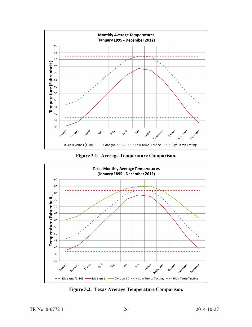
TR No. 0-6772-1 26 2014-10-27
Figure 3.1. Average Temperature Comparison.
Figure 3.2. Texas Average Temperature Comparison.

TR No. 0-6772-1 27 2014-10-27
Figure 3.3. Climatological Division Chart.

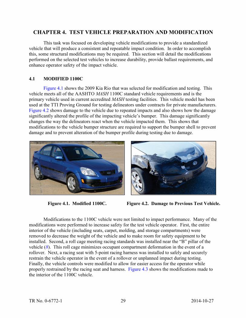
TR No. 0-6772-1 29 2014-10-27
CHAPTER 4. TEST VEHICLE PREPARATION AND MODIFICATION
This task was focused on developing vehicle modifications to provide a standardized vehicle that will produce a consistent and repeatable impact condition. In order to accomplish this, some structural modifications may be required. This section will detail the modifications performed on the selected test vehicles to increase durability, provide ballast requirements, and enhance operator safety of the impact vehicle.
4.1 MODIFIED 1100C
Figure 4.1 shows the 2009 Kia Rio that was selected for modification and testing. This vehicle meets all of the AASHTO MASH 1100C standard vehicle requirements and is the primary vehicle used in current accredited MASH testing facilities. This vehicle model has been used at the TTI Proving Ground for testing delineators under contracts for private manufacturers. Figure 4.2 shows damage to the vehicle due to repeated impacts and also shows how the damage significantly altered the profile of the impacting vehicle’s bumper. This damage significantly changes the way the delineators react when the vehicle impacted them. This shows that modifications to the vehicle bumper structure are required to support the bumper shell to prevent damage and to prevent alteration of the bumper profile during testing due to damage.
Figure 4.1. Modified 1100C. Figure 4.2. Damage to Previous Test Vehicle.
Modifications to the 1100C vehicle were not limited to impact performance. Many of the
modifications were performed to increase safety for the test vehicle operator. First, the entire interior of the vehicle (including seats, carpet, molding, and storage compartments) were removed to decrease the weight of the vehicle and to make room for safety equipment to be installed. Second, a roll cage meeting racing standards was installed near the “B” pillar of the vehicle (8). This roll cage minimizes occupant compartment deformation in the event of a rollover. Next, a racing seat with 5-point racing harness was installed to safely and securely restrain the vehicle operator in the event of a rollover or unplanned impact during testing. Finally, the vehicle controls were modified to allow for easier access for the operator while properly restrained by the racing seat and harness. Figure 4.3 shows the modifications made to the interior of the 1100C vehicle.
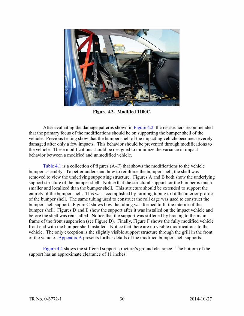
TR No. 0-6772-1 30 2014-10-27
Figure 4.3. Modified 1100C.
After evaluating the damage patterns shown in Figure 4.2, the researchers recommended
that the primary focus of the modifications should be on supporting the bumper shell of the vehicle. Previous testing show that the bumper shell of the impacting vehicle becomes severely damaged after only a few impacts. This behavior should be prevented through modifications to the vehicle. These modifications should be designed to minimize the variance in impact behavior between a modified and unmodified vehicle.
Table 4.1 is a collection of figures (A–F) that shows the modifications to the vehicle bumper assembly. To better understand how to reinforce the bumper shell, the shell was removed to view the underlying supporting structure. Figures A and B both show the underlying support structure of the bumper shell. Notice that the structural support for the bumper is much smaller and localized than the bumper shell. This structure should be extended to support the entirety of the bumper shell. This was accomplished by forming tubing to fit the interior profile of the bumper shell. The same tubing used to construct the roll cage was used to construct the bumper shell support. Figure C shows how the tubing was formed to fit the interior of the bumper shell. Figures D and E show the support after it was installed on the impact vehicle and before the shell was reinstalled. Notice that the support was stiffened by bracing to the main frame of the front suspension (see Figure D). Finally, Figure F shows the fully modified vehicle front end with the bumper shell installed. Notice that there are no visible modifications to the vehicle. The only exception is the slightly visible support structure through the grill in the front of the vehicle. Appendix A presents further details of the modified bumper shell supports.
Figure 4.4 shows the stiffened support structure’s ground clearance. The bottom of the
support has an approximate clearance of 11 inches.

TR No. 0-6772-1 31 2014-10-27
Table 4.1. Vehicle Bumper Modifications.
A: Unmodified Bumper (Side View) B: Unmodified Bumper (Front View)
C: Modified Bumper Inside Bumper Shell D: Modified Bumper (Front View)
E: Modified Bumper (Side View) F: Reassembled Modified Bumper

TR No. 0-6772-1 32 2014-10-27
Figure 4.4. Modified Bumper Ground Clearance.
4.2 MODIFIED 2270P
A 2003 Dodge Quad Cab, shown in Figure 4.5, was selected to represent the MASH 2270P impact vehicle. This vehicle had been used previously in MASH compliance testing of a curb mounted delineator system. The truck was selected to reduce the cost of the project while still meeting the requirements of MASH 2270P specifications. Notice that only cosmetic damage was induced during testing. This minimizes the list of modifications required to perform the proposed low-speed impact tests. However, similar to the modified 1100C impact vehicle, the interior of the pickup truck was removed and safety equipment was installed to protect the operator of the test vehicle. Figure 4.6 shows the interior of the modified vehicle.

TR No. 0-6772-1 33 2014-10-27
Figure 4.5. Modified 2270P.
Figure 4.6. 2270P Vehicle Modifications.
4.3 HEAVY TRANSIT VEHICLE
To replicate a transit class vehicle, a 1996 Thomas School Bus, shown in Figure 4.7, was selected. This vehicle was selected for its rear axle capacity and its low ground clearance (~14 inches). This low ground clearance and high axle weight produces a severe impact condition for delineators. To increase the rear axle weight to 20,000 lb (axle capacity) certain modifications were made to the impacting vehicle. First, all of the seats were removed from the interior of the passenger area of the bus (see Figure 4.8). This made it easier for our mechanic technicians to ballast the impacting vehicle. Another reason this vehicle was selected was due to the rigidity and safety requirements this class of vehicle must meet to transport passengers. Due to these added safety requirements and the low-impact speed, further safety equipment was not deemed necessary to protect the operator of the vehicle. Finally, to bring the rear axle weight up to 20,000 lb, eight barrels (shown in Figure 4.9) were installed in the bus near the rear axle. Each barrel was loaded with sand and weighted approximately 650 lb. The eight barrels were fastened together using two ratchet straps to prevent the ballast from shifting during testing. The final rear axle weight was measured to be 20,050 lb.

TR No. 0-6772-1 34 2014-10-27
Figure 4.7. Heavy Transit Vehicle.
Figure 4.8. Heavy Transit Vehicle Modifications.
Figure 4.9. Vehicle Ballast.
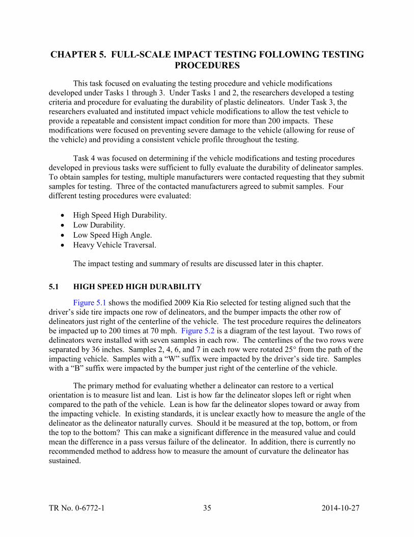
TR No. 0-6772-1 35 2014-10-27
CHAPTER 5. FULL-SCALE IMPACT TESTING FOLLOWING TESTING PROCEDURES
This task focused on evaluating the testing procedure and vehicle modifications developed under Tasks 1 through 3. Under Tasks 1 and 2, the researchers developed a testing criteria and procedure for evaluating the durability of plastic delineators. Under Task 3, the researchers evaluated and instituted impact vehicle modifications to allow the test vehicle to provide a repeatable and consistent impact condition for more than 200 impacts. These modifications were focused on preventing severe damage to the vehicle (allowing for reuse of the vehicle) and providing a consistent vehicle profile throughout the testing.
Task 4 was focused on determining if the vehicle modifications and testing procedures developed in previous tasks were sufficient to fully evaluate the durability of delineator samples. To obtain samples for testing, multiple manufacturers were contacted requesting that they submit samples for testing. Three of the contacted manufacturers agreed to submit samples. Four different testing procedures were evaluated:
• High Speed High Durability. • Low Durability. • Low Speed High Angle. • Heavy Vehicle Traversal.
The impact testing and summary of results are discussed later in this chapter.
5.1 HIGH SPEED HIGH DURABILITY
Figure 5.1 shows the modified 2009 Kia Rio selected for testing aligned such that the driver’s side tire impacts one row of delineators, and the bumper impacts the other row of delineators just right of the centerline of the vehicle. The test procedure requires the delineators be impacted up to 200 times at 70 mph. Figure 5.2 is a diagram of the test layout. Two rows of delineators were installed with seven samples in each row. The centerlines of the two rows were separated by 36 inches. Samples 2, 4, 6, and 7 in each row were rotated 25° from the path of the impacting vehicle. Samples with a “W” suffix were impacted by the driver’s side tire. Samples with a “B” suffix were impacted by the bumper just right of the centerline of the vehicle.
The primary method for evaluating whether a delineator can restore to a vertical orientation is to measure list and lean. List is how far the delineator slopes left or right when compared to the path of the vehicle. Lean is how far the delineator slopes toward or away from the impacting vehicle. In existing standards, it is unclear exactly how to measure the angle of the delineator as the delineator naturally curves. Should it be measured at the top, bottom, or from the top to the bottom? This can make a significant difference in the measured value and could mean the difference in a pass versus failure of the delineator. In addition, there is currently no recommended method to address how to measure the amount of curvature the delineator has sustained.

TR No. 0-6772-1 36 2014-10-27
Figure 5.1. 1100C Impact Position before Testing.
Figure 5.2. High Durability Test Sample Layout.
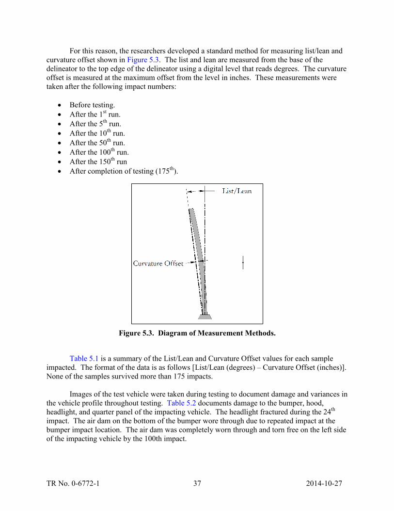
TR No. 0-6772-1 37 2014-10-27
For this reason, the researchers developed a standard method for measuring list/lean and curvature offset shown in Figure 5.3. The list and lean are measured from the base of the delineator to the top edge of the delineator using a digital level that reads degrees. The curvature offset is measured at the maximum offset from the level in inches. These measurements were taken after the following impact numbers:
• Before testing. • After the 1st run. • After the 5th run. • After the 10th run. • After the 50th run. • After the 100th run. • After the 150th run • After completion of testing (175th).
Figure 5.3. Diagram of Measurement Methods.
Table 5.1 is a summary of the List/Lean and Curvature Offset values for each sample
impacted. The format of the data is as follows [List/Lean (degrees) – Curvature Offset (inches)]. None of the samples survived more than 175 impacts.
Images of the test vehicle were taken during testing to document damage and variances in
the vehicle profile throughout testing. Table 5.2 documents damage to the bumper, hood, headlight, and quarter panel of the impacting vehicle. The headlight fractured during the 24th impact. The air dam on the bottom of the bumper wore through due to repeated impact at the bumper impact location. The air dam was completely worn through and torn free on the left side of the impacting vehicle by the 100th impact.

TR No. 0-6772-1 38 2014-10-27
Table 5.1. Test Sample List/Lean and Curvature Offset Summary.
Table 5.2. Modified Vehicle Impact Damage.
A: Before Testing B: After 1 Impact
Impact # List Lean List Lean List Lean List Lean List Lean List LeanBefore Testing 90 - 0 90 - 0 90 - 0 90 - 0 89 - 0 90 - 0 89-0 90-0 89-1/4 89-0 89-0 90-0
1 89 - 0 89 - 0 88 - 0 90 - 1/4 88 - 1/4 90 - 0 88-1/4 89-0 89-1/4 89-0 88-0 90-05 89 - 0 89 - 0 88 - 0 88 - 0 87 - 1/4 89 -0 87-1/4 88-0 89-1/4 88-0 87-1/4 88-0
10 90 - 0 90 - 0 87 - 0 86 - 0 86 - 1/4 88 - 0 88-1/4 88-1/8 88-1/4 87-0 89-1/4 87-050 87 - 0 88 - 1/8 86-1/4 86-1/4 89-1/4 86-0 87-1/8 86-3/8
100 86-1/4 86-1/4 87-1/8 86-1/4150 85-1/4 86-1/4 86-0 85-1/4200
Failure/Final # 92 46 17 56 175 175
List Lean List Lean List Lean List Lean List Lean List LeanBefore Testing 88 - 1/4 90 - 0 90 - 0 89 - 0 89 - 0 90 - 0 88-1/4 89-0 89-1/2 89-0 89-1/4 90-0
1 88 - 1/4 87 - 0 90 - 0 86 - 0 90 - 0 88 - 0 89-1/4 86-0 87-3/4 90-1/4 89-1/4 89-05 88 - 1/4 86 - 1/8 90 - 0 85 - 0 89 - 1/8 87 - 0 86-3/4 88-1/4 89-1/4 88-0
10 88 - 1/4 85 - 1/8 90 - 1/8 83 - 0 87-3/4 88-1/8 89-1/4 88-050 89 - 1/4 89 - 0 87-1/2 86-1/4
100150200
Failure/Final # 57 16 6 5 59 48
List Lean List Lean Driver's headlight failed @ 24Before Testing 89-0 90-0 89-0 90-0 1T - @7, 13, 15 lean righted
1 87-1/4 88-0 1T - @35, 38, 40, 475
1050
100150200
Failure/Final # 3 1
7T 7B
High Speed High Durability - Post # (2013-08-19)
1B 2B 3B 4B 5B 6B
1T 2T 3T 4T 5T 6T

TR No. 0-6772-1 39 2014-10-27
Table 5.2. Modified Vehicle Impact Damage (Continued).
C: After 5 Impacts D: After 10 Impacts
E: After 24 Impacts F: After 50 Impacts
G: Bumper After 50 Impacts H: After 100 Impacts
I: After 150 Impacts J: After 175 Impacts

TR No. 0-6772-1 40 2014-10-27
Images of reflective sheeting, post deformation, and post base or post failure mode were documented after the following impact numbers:
• Before testing. • After the 1st run. • After the 5th run. • After the 10th run. • After the 50th run. • After the 100th run. • After the 150th run. • After completion of testing (175th).
There are up to 24 pictures for each sample (in this case 14 sample posts). This project
was focused on evaluating the impact vehicle and test procedure and not evaluation of the test samples. For this reason, only one table of images for one post sample are included in this memo as an example of how the damage to the post and reflective sheeting was documented. Table 5.3 is an example table for sample post # 5W.
5.2 LOW DURABILITY
Figure 5.4 shows the modified 2009 Kia Rio selected for testing after it was repaired. The entire hood, driver’s side quarter panel, bumper shell assembly, and driver’s side headlight were replaced. None of the vehicle’s structural or powertrain components were damaged during previous testing. Again, the vehicle was aligned such that the driver’s side tire impacts one row of delineators, and the bumper impacts the other row of delineators just right of the centerline of the vehicle. The test procedure requires the delineators be impacted up to 10 times at 50 mph. Figure 5.5 is a diagram of the test layout. Two rows of delineators were installed with six samples installed in each row. The centerlines of the two rows were separated by 36 inches. Samples 2, 4, and 6 in each row were rotated 25° from the path of the impacting vehicle. Samples with a “W” suffix were impacted by the driver side tire. Samples with a “B” suffix were impacted by the bumper just right of the centerline of the vehicle. The first four samples in each row were installed in Georgetown road base, graded, and compacted to meet AASHTO MASH standards. See Appendix B for further details of the road base used in testing.
Again, the researchers used the standard method for measuring list/lean and curvature
offset shown in Figure 5.3. The list and lean was measured from the base of the delineator to the top edge of the delineator using a digital level that reads degrees. The curvature offset was measured at the maximum offset from the level in inches. These measurements were taken after the following impact numbers:
• Before testing. • After the 1st run. • After the 5th run. • After the 10th run.

TR No. 0-6772-1 41 2014-10-27
Table 5.3. Post Damage Documentation – Sample Post # 5W.
Run # Reflective Sheeting Full Post Base or DamageBe
fore
Tes
ting
15
1050
Photos - Post # 5W

TR No. 0-6772-1 42 2014-10-27
Table 5.3. Post Damage Documentation – Sample Post # 5W (Continued).
Run # Reflective Sheeting Full Post Base or Damage10
015
020
0Fa
ilure
/Fin
al 1
80
Photos - Post # 5W

TR No. 0-6772-1 43 2014-10-27
Figure 5.4. 1100C after Being Repaired and before Low Durability Testing.
Table 5.4 is a summary of the list/lean and curvature offset values for each sample
impacted. The format of the data is as follows: list/lean (degrees) – curvature offset (inches).
Images of the test vehicle were taken during testing to document damage and variances in the vehicle profile throughout testing. Table 5.5 documents damage to the bumper, hood, headlight, and quarter panel of the impacting vehicle.

TR No. 0-6772-1 44 2014-10-27
Fi
gure
5.5
. L
ow D
urab
ility
Tes
t Sam
ple
Lay
out.

TR No. 0-6772-1 45 2014-10-27
Table 5.4. Test Sample List/Lean and Curvature Offset Summary.
Table 5.5. Modified Vehicle Impact Damage.
A: Before Testing B: After 1 Impact
C: After 5 Impacts D: After 10 Impacts
Impact # List Lean List Lean List Lean List Lean List Lean List LeanBefore Testing 89-0 89-0 87-0 89-0 90-0 87-1/8 90-0 90-0 89-0 89-0 90-0 88-0
@ 8:55 1 89-0 88-0 90-0 86-1/4 90-0 87-0 90-0 90-0 89-0 89-05 89-0 90-1/8 89-0 88-1/4 87-1/2 85-1 89-1/2 89-0 88-1/4 83-3
10 90-0 90-1/4 89-0 86-1/4 86-1/2 83-2 87-1 89-1/2 86-2 76-4Failure/Final # 1 10 10 10 10 10
List Lean List Lean List Lean List Lean List Lean List LeanBefore Testing 88-1/8 90-0 87-0 89-0 90-0 88-1/8 87-1/4 87-1/4 88-0 90-0 89-0 90-0
1 88-1/8 86-0 88-0 88-0 89-0 90-1/8 87-1/4 89-1/8 89-0 90-0 90-0 90-05 88-0 84-1/8 87-0 86-1/4 89-0 90-1/4 86-1/2 89-1/4 89-0 89-0 89-0 90-0
10 88-0 83-1/4 87-0 85-1/2 89-1/8 90-1/2 86-1/2 89-1/4 89-0 89-0 90-0 89-0Failure/Final # 10 10 10 10 10 10
Post leaned to 35 deg after test 1 - Post returned to vertical after a few minutes (creased at gound level)
1B 2B 3B 4B 5B 6B
Low Durability - Post # (2013-08-21)1T 2T 3T 4T 5T 6T

TR No. 0-6772-1 46 2014-10-27
5.3 LOW SPEED HIGH ANGLE
A modified 1100C (2009 Kia Rio) and unmodified 2270P (Dodge Quad Cab ½-ton pickup) were selected for testing. Neither vehicle was repaired before the beginning of this phase of testing. None of the vehicles’ structural or powertrain components were damaged during previous testing. The previous testing had not significantly changed the bumper profile. Again, the vehicles were aligned such that the driver’s side tires impacted one row of delineators. Two rows of delineators were installed, one for each impact vehicle used. The test procedure required the delineators to be impacted up to 200 times at 20 mph. Figure 5.6 is a diagram of the test layout. Six samples were installed in each row. The centerlines of the two rows are separated by approximately 26 ft. All samples were rotated 90° from the path of the impacting vehicle. Samples with a “C” suffix were impacted by the driver’s side tire of the 1100C. Samples with a “T” suffix were impacted by the driver’s side tire of the 2270P.
Again, the researchers used the standard method for measuring list/lean and curvature offset shown in Figure 5.3. The list and lean were measured from the base of the delineator to the top edge of the delineator using a digital level that reads degrees. The curvature offset was measured at the maximum offset from level in inches. These measurements were taken after the following impact numbers:
• Before testing. • After the 1st run. • After the 5th run. • After the 10th run. • After the 50th run. • After the 100th run. • After the 150th run. • After completion of testing (180th).
Table 5.6 summarizes the list/lean and curvature offset values for each sample impacted.
The format of the data is as follows: List/lean (degrees) – curvature offset (inches).
Images of the test vehicles were taken during testing to document damage and variances in the vehicle profile throughout testing. Table 5.7 documents damage to the bumper, hood, headlight, and quarter panel of the impacting vehicles.

TR No. 0-6772-1 47 2014-10-27
Figu
re 5
.6.
Low
Spe
ed H
igh
Ang
le T
est S
ampl
e L
ayou
t.
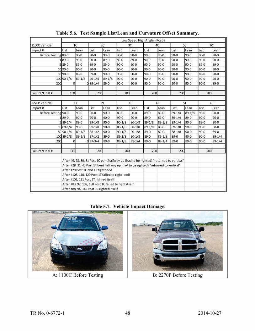
TR No. 0-6772-1 48 2014-10-27
Table 5.6. Test Sample List/Lean and Curvature Offset Summary.
Table 5.7. Vehicle Impact Damage.
A: 1100C Before Testing B: 2270P Before Testing
1100C VehicleImpact # List Lean List Lean List Lean List Lean List Lean List Lean
Before Testing 89-0 90-0 90-0 90-0 90-0 90-0 90-0 90-0 90-0 90-0 90-0 90-01 89-0 90-0 90-0 89-0 89-0 89-0 90-0 90-0 90-0 90-0 90-0 90-05 89-0 89-0 89-0 89-0 90-0 90-0 90-0 90-0 90-0 90-0 89-0 89-0
10 90-0 90-0 90-0 90-0 90-0 90-0 90-0 90-0 90-0 90-0 90-0 90-050 90-0 89-0 89-0 90-0 90-0 90-0 90-0 90-0 90-0 90-0 89-0 90-0
100 90-1/8 89-1/8 90-1/4 89-1/8 90-0 90-0 90-0 90-0 90-0 90-0 90-0 90-0200 0 0 89-1/4 89-0 90-0 90-0 90-0 90-0 90-0 90-0 90-0 89-0
Failure/Final # 150 200 200 200 200 200
2270P VehicleImpact # List Lean List Lean List Lean List Lean List Lean List Lean
Before Testing 90-0 90-0 90-0 90-0 89-0 90-0 89-0 89-0 89-1/4 89-1/8 90-0 90-01 89-0 90-0 90-0 90-0 90-0 90-0 89-0 89-0 89-1/4 89-0 90-0 90-05 89-1/4 89-0 89-1/8 90-0 90-1/8 90-1/8 89-1/8 89-1/8 89-1/4 90-0 89-0 90-0
10 89-1/4 90-0 89-1/8 90-0 89-1/8 90-1/8 89-1/8 89-0 89-1/8 90-0 90-0 90-050 90-1/4 89-1/8 88-1/2 90-0 90-1/8 90-1/8 89-0 89-0 88-1/8 90-0 90-0 89-0
100 89-1/8 89-1/8 87-1/2 89-0 89-1/8 90-1/8 89-0 89-1/8 89-0 90-0 90-0 89-1/4200 0 0 87-3/4 89-0 89-1/8 89-1/4 89-0 89-1/4 89-0 89-0 90-0 89-1/4
Failure/Final # 111 200 200 200 200 200
After #9, 78, 80, 81 Post 1C bent halfway up (had to be righted) "returned to vertical"After #28, 31, 43 Post 1T bent halfway up (had to be righted) "returned to vertical"After #29 Post 1C and 1T tightenedAfter #108, 110, 120 Post 1T failed to right itselfAfter #109, 111 Post 1T righted itselfAfter #83, 92, 109, 150 Post 1C failed to right itselfAfter #88, 94, 145 Post 1C righted itself
6T
Low Speed High Angle - Post # 1C 2C 3C 4C 5C 6C
1T 2T 3T 4T 5T
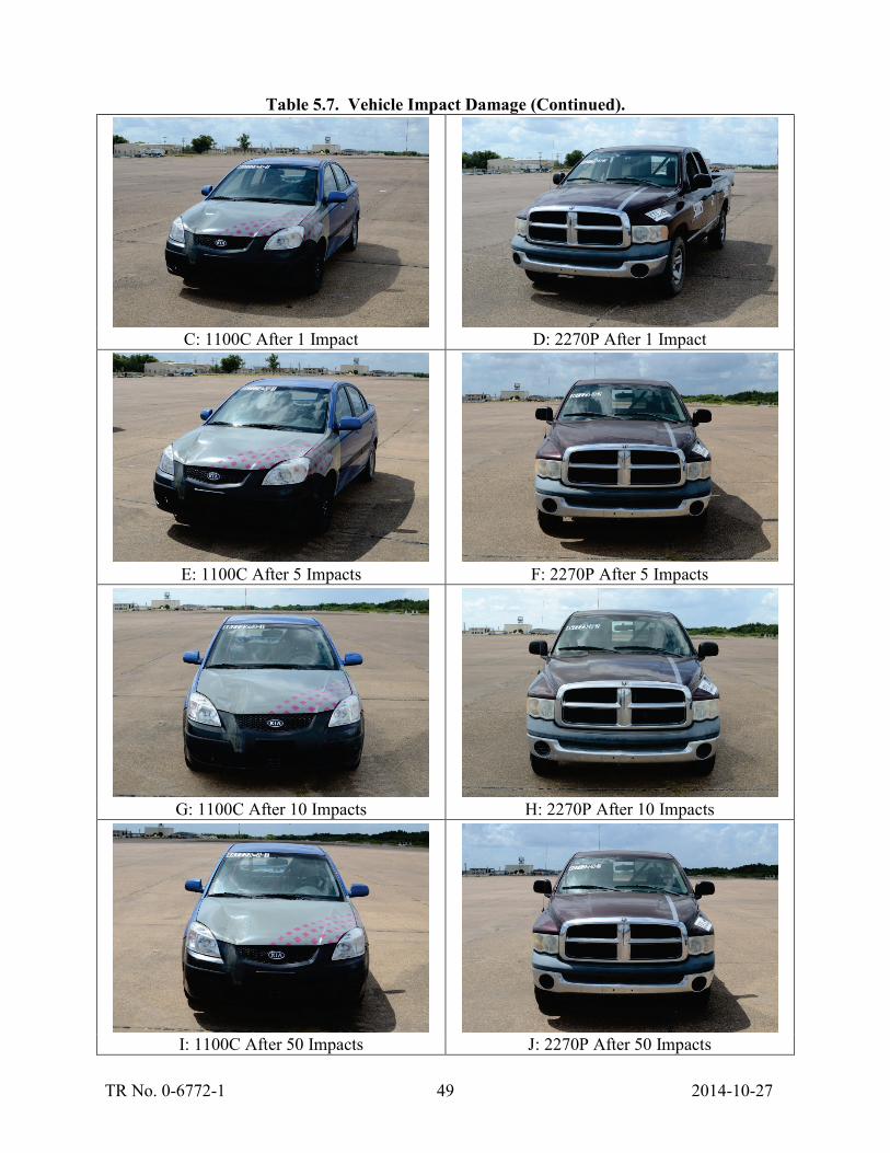
TR No. 0-6772-1 49 2014-10-27
Table 5.7. Vehicle Impact Damage (Continued).
C: 1100C After 1 Impact D: 2270P After 1 Impact
E: 1100C After 5 Impacts F: 2270P After 5 Impacts
G: 1100C After 10 Impacts H: 2270P After 10 Impacts
I: 1100C After 50 Impacts J: 2270P After 50 Impacts

TR No. 0-6772-1 50 2014-10-27
Table 5.7. Vehicle Impact Damage (Continued).
K: 1100C After 100 Impacts L: 2270P After 100 Impacts
M: 1100C After 200 Impacts N: 2270P After 200 Impacts
5.4 HEAVY VEHICLE TRAVERSALS
Figure 5.7 shows the modified transit vehicle selected for testing. This vehicle was previously used in a crash test on an unrelated project. None of the vehicle’s structural, powertrain, or body components were damaged during the previous testing. The vehicle was aligned such that the driver’s side rear tandem tires impacted one row of delineators installed on a 125-foot diameter arc. The test procedure required the delineators be impacted up to 200 times at a speed between 10 mph and 20 mph. Figure 5.8 is a diagram of the test layout. A total of 14 samples were installed in single row. All samples were rotated to align the delineators with the tangent of the circle.
Again, the researchers used the standard method for measuring list/lean and curvature offset shown in Figure 5.3. The list and lean was measured from the base of the delineator to the top edge of the delineator using a digital level that reads degrees. The curvature offset was measured at the maximum offset from the level in inches. These measurements were taken after the following impact numbers:
• Before testing. • After the 1st run. • After the 5th run. • After the 10th run.
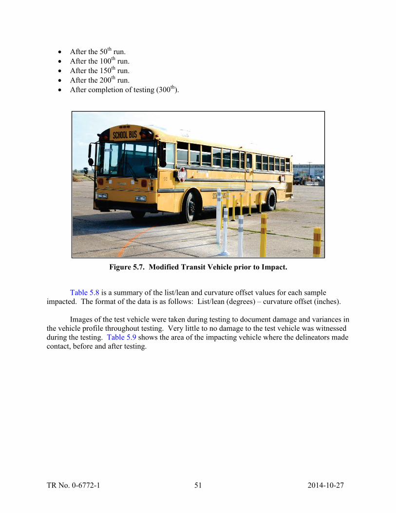
TR No. 0-6772-1 51 2014-10-27
• After the 50th run. • After the 100th run. • After the 150th run. • After the 200th run. • After completion of testing (300th).
Figure 5.7. Modified Transit Vehicle prior to Impact.
Table 5.8 is a summary of the list/lean and curvature offset values for each sample
impacted. The format of the data is as follows: List/lean (degrees) – curvature offset (inches).
Images of the test vehicle were taken during testing to document damage and variances in the vehicle profile throughout testing. Very little to no damage to the test vehicle was witnessed during the testing. Table 5.9 shows the area of the impacting vehicle where the delineators made contact, before and after testing.

TR No. 0-6772-1 52 2014-10-27
Fi
gure
5.8
. H
eavy
Veh
icle
Tra
vers
al T
est S
ampl
e L
ayou
t.

TR No. 0-6772-1 53 2014-10-27
Table 5.8. Test Sample List/Lean and Curvature Offset Summary.
Table 5.9. Modified Vehicle Impact Damage.
A: Before Testing (0 Impacts) B: After 300 Impacts
Impact # List Lean List Lean List Lean List Lean List Lean List LeanBefore Testing 90-0 90-0 90-0 90-0 90-0 90-0 90-0 89-0 90-0 90-0 90-0 90-0
1 90-0 90-0 90-0 90-0 90-0 90-0 90-0 90-0 89-0 90-0 90-0 90-05 90-0 89-0 90-1/8 89-1/8 90-1/8 90-0 90-1/8 90-0 90-0 90-0 90-1/8 90-1/8
10 90-0 89-0 90-1/4 89-0 90-1/8 89-0 90-1/8 90-1/8 90-1/8 90-1/8 90-1/8 90-1/850 90-0 89-0 90-1/8 89-0 90-1/8 89-1/8 90-1/8 90-1/8 89-1/8 89-1/8 90-0 90-1/8
100 89-1/4 89-1/8 90-1/8 89-1/8 89-1/8 89-1/8 90-1/8 90-1/8 89-1/8 90-1/8 90-1/8 90-1/4200 90-1/8 89-0 90-1/8 90-1/4 89-0 90-1/4 90-1/4 90-1/4 89-0 89-1/8 90-1/8 90-1/4300 89-1/8 89-1/8 90-1/4 90-1/4 89-1/8 89-1/4 90-1/4 90-1/8 89-0 89-1/8 89-0 89-1/2
Failure/Final # 300 300 300 300 300 300
List Lean List Lean List Lean List Lean List Lean List LeanBefore Testing 90-0 89-1/8 90-0 88-1/8 90-0 90-0 90-0 90-0 90-0 90-0 90-0 90-0
1 90-0 88-0 90-0 88-1/8 90-0 90-0 90-0 90-0 90-0 90-0 90-0 89-05 90-1/4 89-1/4 88-1/4 90-1/4 89-1/8 89-0 90-0 89-1/8 90-1/8 89-1/8 90-1/8 89-1/8
10 90-1/8 89-1/4 90-1/8 88-1/4 89-1/8 90-1/8 89-0 89-1/8 90-1/8 90-1/8 90-1/8 89-050 90-1/8 89-1/4 90-1/8 88-1/4 89-1/8 90-1/4 88-1/8 89-1/4 89-0 90-0 90-0 89-1/8
100 87-1/4 90-1/4 88-1/8 89-1/4 89-0 89-1/8 89-1/8 90-1/4200 87-1/4 90-3/8 88-1/8 89-3/8 89-0 89-1/4 89-1/8 89-1/4300 87-1/4 90-3/8 88-1/8 89-3/8 89-0 89-1/4 89-0 89-1/4
Failure/Final # 73 96 300 300 300 300
List Lean List Lean After 73 Post 7 layed Over - Failed to right itselfBefore Testing 90-0 90-0 90-0 88-1/8 After 79, 96 Post 8 layed Over - Failed to right itself
1 90-0 89-0 90-0 88-1/8 After 95 Post 8 righted itself5 90-0 90-0 90-0 88-1/4
10 90-0 90-0 90-1/8 88-1/850 90-0 90-0 89-0 88-1/8
100 90-0 90-0 90-0 88-1/8200 89-1/8 89-1/4 90-0 88-1/8300 90-0 89-1/4 89-1/8 88-1/8
Failure/Final # 300 300
13 14
7 8 9 10 11 12
Heavy Vehicle Traversal - Post # 1 2 3 4 5 6

TR No. 0-6772-1 54 2014-10-27
5.5 WITNESSED FAILURE MODES
Multiple failure modes were witnessed during testing of the delineator samples using the various testing procedures. Table 5.10 is a collection of photos showing common failure modes of delineators. In addition to these failure modes, the researchers have also witnessed, on multiple occasions while testing products on unrelated projects, the disengagement of the base and the roadway surface. This failure mode has also been witnessed in the field. This failure mode has been witnessed extensively with the use of epoxy, mechanical anchors, and heat sensitive polymer pads; however, this failure mode was not witnessed during this series of testing.
Table 5.10. Witnessed Delineator Failure Modes.
A: Failure to Restore to Upright Position B: Failure to Restore to Upright Position
C: Excessive List/Lean/Curvature D: Excessive List/Lean/Curvature
E: Post Rupture F: Post Rupture (at base)

TR No. 0-6772-1 55 2014-10-27
Table 5.10. Witnessed Delineator Failure Modes (Continued).
G: Post Rupture (at base) H: Post Rupture (at base)
I: Bolt Failure
The reflective sheeting and posts take a tremendous amount of abuse during impact testing. During the testing, the reflective sheeting becomes damaged and the posts become discolored. Some of this discoloration is due to tire impacts, but much of it is due to contact with vehicle components. Table 5.11 shows this abuse can lead to a significant loss in both visibility and reflectivity. Images of the reflective sheeting were taken to document the sheeting loss and the discoloration of the posts each time the posts are measured for list/lean and curvature offset.
Table 5.11. Post Discoloration and Reflective Sheeting Damage.
A: Before Testing B: After 175 Impacts


TR No. 0-6772-1 57 2014-10-27
CHAPTER 6. RE-EVALUATION OF TESTING STANDARD AND TEST VEHICLE MODIFICATIONS
This task was focused on re-evaluating the testing procedure and vehicle modifications developed under Tasks 1 through 3 and performed under Task 4. Under Tasks 1 and 2, the researchers developed a testing criteria and procedure for evaluating the durability of plastic delineators. Under Task 3, the researchers evaluated and instituted impact vehicle modifications to allow the test vehicle to provide a repeatable and consistent impact condition for more than 200 impacts. These modifications were focused on preventing severe damage to the vehicle (allowing for reuse of the vehicle), and providing a consistent vehicle profile throughout the testing.
Task 4 was focused on determining if the vehicle modifications and testing procedures developed in previous tasks were sufficient to fully evaluate the durability of delineator samples. To obtain samples for testing, multiple manufacturers were contacted requesting that they submit samples for testing. Three of the contacted manufacturers agreed to submit samples. Four different testing procedures were evaluated under this task:
• High Speed High Durability. • Low Durability. • Low Speed High Angle. • Heavy Vehicle Traversal.
6.1 EVALUATION OF PREVIOUSLY RECOMMENDED TESTING CATEGORIES
After evaluation of the results from testing performed under Task 3, it has been determined that Low Speed High Angle and Heavy Vehicle Traversal categories are not efficient methods of determining durability of the delineators submitted for testing. Researchers found that while the tests resulted in a proper evaluation of the products, it required a significantly higher number of impacts to come to the same results witnessed in the High Speed High Durability testing. These categories also require the use of multiple impact vehicle types, which would lead to increased testing costs for insignificantly different evaluation of the products. For these reason the researchers suggest that these two categories be replaced with a 5th category (High Durability Metropolitan Delineator).
Results of the cold weather test performed earlier this year, at a lower impact speed (55 mph) due to weather conditions, showed significantly different results then the previous summer’s High Temp testing at High Speed. It has not yet been determined whether the cold temperatures or the lower impact speed were the cause of the discrepancy in the results of the testing. The researchers suggested the creation of a “High Durability Metropolitan Delineator” testing standard. This testing would be identical to the High Speed High Durability standard with the exception of impact speed. This test would be performed at 55 mph instead of 70 mph to simulate impact speeds that are better represented by smaller metropolitan roadways. The cold weather testing performed in January 2014 was scheduled to be repeated later in summer 2014 at both 55 mph and 70 mph to determine if temperature and speed, or both, were the primary causes of the discrepancies in the results. If it is determined that speed is not a primary

TR No. 0-6772-1 58 2014-10-27
cause of the discrepancy, then the researchers suggest this category also be dropped from the standard.
6.2 LIST AND LEAN
Previously, the primary method for evaluating whether a delineator can restore to a vertical orientation was to measure list and lean. List is how far the delineator slopes left or right when compared to the path of the vehicle. Lean is how far the delineator slopes toward or away from the impacting vehicle. In existing standards, it is unclear exactly how to measure the angle of the delineator as the delineator naturally curves. Should it be measured at the top, bottom, or from the top to the bottom? This can make a significant difference in the measured value and could mean the difference in a pass versus failure of the delineator. In addition, should the angle to which a delineator lists/leans in a third axis (combination of list and lean) be considered when determining if a delineator has failed? Finally, there is currently no recommended method to address how to measure the amount of curvature the delineator has sustained.
For this reason, the researchers developed a standard method for measuring List/Lean and curvature offset, shown in Figure 6.1. Table 6.1 shows the list and lean measured from the base of the delineator to the top edge of the delineator using a digital level that reads degrees as an example. The Curvature Offset is measured at the maximum offset from the level in inches.
These measurements were taken after the following impact numbers:
• Before testing. • After the 1st run. • After the 5th run. • After the 10th run. • After the 50th run. • After the 100th run. • After the 150th run • After completion of testing (200th run).
Figure 6.1. Diagram of Measurement Methods.

TR No. 0-6772-1 59 2014-10-27
Table 6.1. Test Sample List/Lean and Curvature Offset Summary.
When analyzing the results of the List/Lean and Curvature Offset measurements, it was determined that the measurements did not really infer to the evaluator anything about the performance. The samples did not significantly deviate from vertical until right before failure. The addition of the Curvature Offset measurement showed even less correlation to the failure of the product. The only thing that was noted between all of the tests is that once a product listed more than 15°, it would soon fail. Due to the significant time it takes to take these measurements and the minimal amount of information gained from recording them, the researchers recommend that the number of measurements be reduced significantly and that Curvature Offset no longer be evaluated. It is recommended that List/Lean measurement only be taken at the following times:
• Before testing. • After the 1st run. • After the 10th run • After the 100th run. • After the 200th run.
Impact # List Lean List Lean List Lean List Lean List Lean List LeanBefore Testing 90 - 0 90 - 0 90 - 0 90 - 0 89 - 0 90 - 0 89-0 90-0 89-1/4 89-0 89-0 90-0
1 89 - 0 89 - 0 88 - 0 90 - 1/4 88 - 1/4 90 - 0 88-1/4 89-0 89-1/4 89-0 88-0 90-05 89 - 0 89 - 0 88 - 0 88 - 0 87 - 1/4 89 -0 87-1/4 88-0 89-1/4 88-0 87-1/4 88-0
10 90 - 0 90 - 0 87 - 0 86 - 0 86 - 1/4 88 - 0 88-1/4 88-1/8 88-1/4 87-0 89-1/4 87-050 87 - 0 88 - 1/8 86-1/4 86-1/4 89-1/4 86-0 87-1/8 86-3/8
100 86-1/4 86-1/4 87-1/8 86-1/4150 85-1/4 86-1/4 86-0 85-1/4200
Failure/Final # 92 46 17 56 175 175
List Lean List Lean List Lean List Lean List Lean List LeanBefore Testing 88 - 1/4 90 - 0 90 - 0 89 - 0 89 - 0 90 - 0 88-1/4 89-0 89-1/2 89-0 89-1/4 90-0
1 88 - 1/4 87 - 0 90 - 0 86 - 0 90 - 0 88 - 0 89-1/4 86-0 87-3/4 90-1/4 89-1/4 89-05 88 - 1/4 86 - 1/8 90 - 0 85 - 0 89 - 1/8 87 - 0 86-3/4 88-1/4 89-1/4 88-0
10 88 - 1/4 85 - 1/8 90 - 1/8 83 - 0 87-3/4 88-1/8 89-1/4 88-050 89 - 1/4 89 - 0 87-1/2 86-1/4
100150200
Failure/Final # 57 16 6 5 59 48
List Lean List Lean Driver's headlight failed @ 24Before Testing 89-0 90-0 89-0 90-0 1T - @7, 13, 15 lean righted
1 87-1/4 88-0 1T - @35, 38, 40, 475
1050
100150200
Failure/Final # 3 1
7T 7B
High Speed High Durability - Post # (2013-08-19)
1B 2B 3B 4B 5B 6B
1T 2T 3T 4T 5T 6T
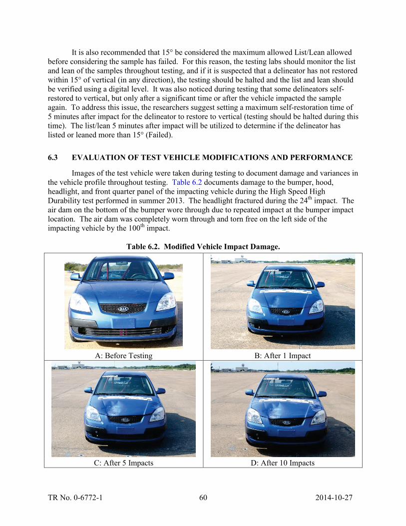
TR No. 0-6772-1 60 2014-10-27
It is also recommended that 15° be considered the maximum allowed List/Lean allowed before considering the sample has failed. For this reason, the testing labs should monitor the list and lean of the samples throughout testing, and if it is suspected that a delineator has not restored within 15° of vertical (in any direction), the testing should be halted and the list and lean should be verified using a digital level. It was also noticed during testing that some delineators self-restored to vertical, but only after a significant time or after the vehicle impacted the sample again. To address this issue, the researchers suggest setting a maximum self-restoration time of 5 minutes after impact for the delineator to restore to vertical (testing should be halted during this time). The list/lean 5 minutes after impact will be utilized to determine if the delineator has listed or leaned more than 15° (Failed).
6.3 EVALUATION OF TEST VEHICLE MODIFICATIONS AND PERFORMANCE
Images of the test vehicle were taken during testing to document damage and variances in the vehicle profile throughout testing. Table 6.2 documents damage to the bumper, hood, headlight, and front quarter panel of the impacting vehicle during the High Speed High Durability test performed in summer 2013. The headlight fractured during the 24th impact. The air dam on the bottom of the bumper wore through due to repeated impact at the bumper impact location. The air dam was completely worn through and torn free on the left side of the impacting vehicle by the 100th impact.
Table 6.2. Modified Vehicle Impact Damage.
A: Before Testing B: After 1 Impact
C: After 5 Impacts D: After 10 Impacts

TR No. 0-6772-1 61 2014-10-27
Table 6.2. Modified Vehicle Impact Damage (Continued).
E: After 24 Impacts F: After 50 Impacts
G: Bumper After 50 Impacts H: After 100 Impacts
I: After 150 Impacts J: After 175 Impacts
Table 6.3 documents damage to the bumper, hood, headlight, and quarter panel of the
impacting vehicle during the Low Temperature High Durability Metropolitan Delineator test performed in January 2014. Notice that the headlamps were purposefully filled with foam to prevent failure as witnessed in summer 2013. The air dam, hood, and quarter panel were almost completely intact. The only significant damage was to the hood where it was dented due to repeated impacts. There was also a short tear in the hood from low cycle fatigue of the sheet metal skin at the location where top of the delineator impacts the hood. The researchers consider the damage to the hood significant; however, they do not believe that it significantly affected the results of the tests. The researchers believe that any attempts to prevent this behavior would in

TR No. 0-6772-1 62 2014-10-27
and of themselves affect the testing and would likely lead to significant increases in the cost of testing. It is thought that the incurred cost would not be outweighed by the better performance of the hood. The researchers believe that the performance witnessed in these two tests are adequate and suggest maintaining the current configuration.
Table 6.3. Modified Vehicle Impact Damage (Low Temp Testing).
A: After 10 Impacts
B: After 200 Impacts
6.4 POST DISCOLORATION AND REFLECTIVE SHEETING RETENTION
The reflective sheeting and posts take a tremendous amount of abuse during impact testing. During the testing, the reflective sheeting becomes damaged and the posts become discolored. Some of this discoloration is due to tire impacts, but much of it is due to contact with vehicle components. Table 6.4 shows this abuse can lead to a significant loss in both visibility and reflectivity. Images of the reflective sheeting were taken to document the sheeting loss and the discoloration of the posts each time the posts are measured for list/lean and curvature offset.
Table 6.4 also shows the difference between cold weather testing at 55 mph and warm weather testing at 70 mph. All four images are of the same product. Notice the reflective sheeting damage is very similar, but the post discoloration is significantly different. It should be noted that it was sleeting during the cold weather testing and could have served to reduce the friction between the post and the vehicle. No ice buildup was noticed in the impact regions of the vehicle. The impact with the vehicle served to remove the ice before it had time to build up.

TR No. 0-6772-1 63 2014-10-27
Table 6.4. Post Discoloration and Reflective Sheeting Damage.
A: Before Testing (Warm Temp) B: After 180 Impacts (Warm Temp)
C: Before Testing (Cold Temp) D: After 150 Impacts (Cold Temp)
There are up to 24 pictures for each sample (generally 8 sample posts). This project was focused on evaluating the impact vehicle and test procedure and not evaluation of the test samples. For this reason, only one table of images for one post sample are included in this memo as an example of how the damage to the post and reflective sheeting was documented. Table 6.5 is an example table for sample post # 5W from warm weather testing in summer 2013. The researchers suggest continuing this method of analysis of sheeting and post damage.

TR No. 0-6772-1 64 2014-10-27
Table 6.5. Post Damage Documentation – Sample Post # 5W.
Run # Reflective Sheeting Full Post Base or DamageBe
fore
Tes
ting
15
1050
Photos - Post # 5W

TR No. 0-6772-1 65 2014-10-27
Table 6.5. Post Damage Documentation – Sample Post # 5W (Continued).
6.5 SUMMARY OF UPDATED TESTING SPECIFICATION
Given the results of testing performed under Task 4, it is recommended that the following test specification be utilized. Final evaluation (performed after completion of all testing) will determine if delineator performance differences noticed in Task 4 and Task 6 were attributed to temperature effects and impact speed effects or both.
Run # Reflective Sheeting Full Post Base or Damage10
015
020
0Fa
ilure
/Fin
al 1
80
Photos - Post # 5W

TR No. 0-6772-1 66 2014-10-27
1. Generic Test Specifications. a. Impact Vehicle: Modified MASH 1100C (small sedan). b. Impact Velocity: Varies.
i. Low Durability Side of Roadway Applications (55 mph) – Maximum of 10 impacts.
ii. High Durability Metropolitan Delineator Applications (55 mph). iii. High Speed High Durability Applications (70 mph).
c. Total Number of Test Samples: 16 delineator posts and 8 bases (8 hot and 8 cold).
d. Hot Test Temp: 82°F or greater. e. Cold Test Temp: 35°F or lower. f. Manufacturer- suggested maximum installed height of delineator shall be tested.
2. Test Installation. a. Two rows of four delineators. b. One row will be aligned with vehicle tire (wheel over impact). c. One row will be aligned with the opposing vehicle quarter point (bumper impact). d. Each delineator will be spaced a minimum of 50 inches (or 2 inches greater than
delineator height) from a subsequent delineator to prevent interaction. e. Half of the bumper and wheel over impacts will be oriented parallel to the path of
the impacting vehicle. f. Half of the bumper and wheel over impacts will be oriented 25° from the path of
the impacting vehicle. 3. Surface Attachment Method.
a. All testing will be performed with the intended product (no substitutions). b. Material/technical specifications must be submitted with each product. c. At least four delineators must be attached with each type of proposed attachment
method: i. At least two of each method must be a bumper impact.
ii. At least two of each method must be a wheel over impact. iii. An equal number of bumper and wheel over impacts will be performed on
each method. d. If more than two attachment methods are proposed:
i. Number of samples tested at one time can be increased at the testing facility’s discretion.
ii. Testing may be repeated with a new set of 4 or more delineator samples to qualify untested methods.
4. Documentation. a. Material classification data shall be submitted with test samples (to be retained by
testing lab). ASTM D5630 (Ash Testing) and Fourier Transform Infrared Spectrometry (FTIR) ASTM E168 and E1252 are preferred methods.
b. Material/technical specifications shall be submitted with test samples (to be included in report).
c. Complete fabrication drawings detailing all component dimensions and thicknesses shall be submitted with test samples (to be retained by testing lab).
d. General drawings shall be submitted with test samples (to be included in report).
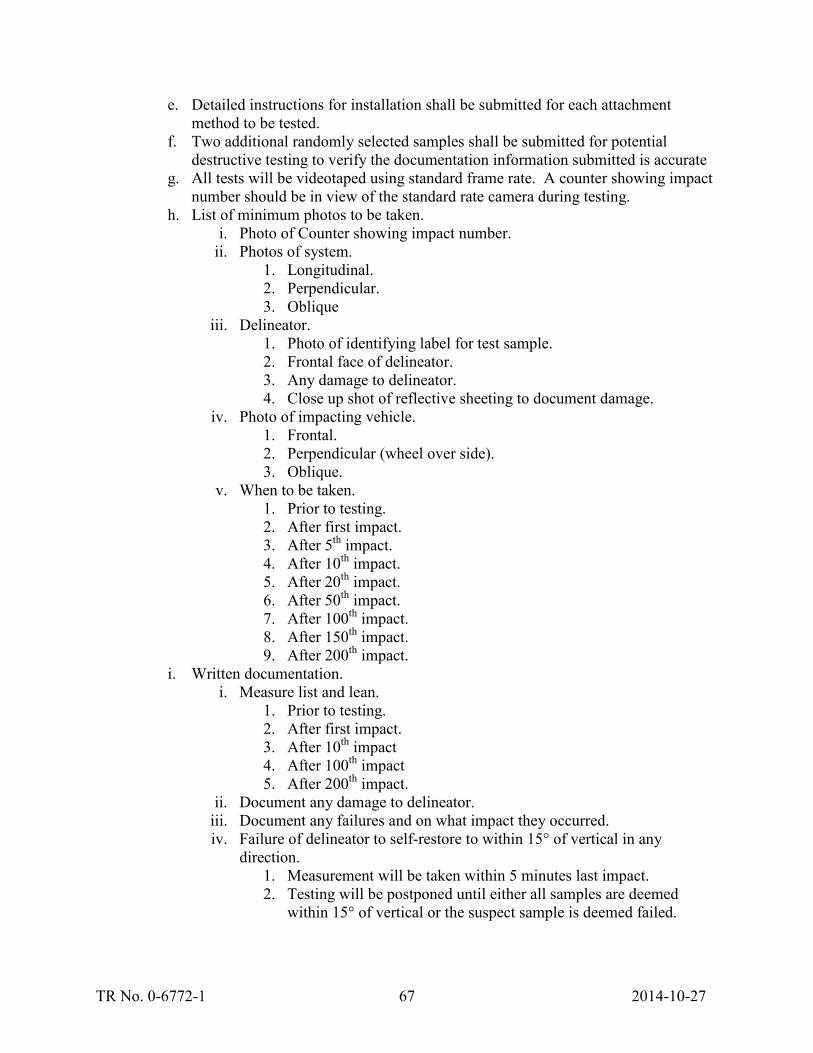
TR No. 0-6772-1 67 2014-10-27
e. Detailed instructions for installation shall be submitted for each attachment method to be tested.
f. Two additional randomly selected samples shall be submitted for potential destructive testing to verify the documentation information submitted is accurate
g. All tests will be videotaped using standard frame rate. A counter showing impact number should be in view of the standard rate camera during testing.
h. List of minimum photos to be taken. i. Photo of Counter showing impact number.
ii. Photos of system. 1. Longitudinal. 2. Perpendicular. 3. Oblique
iii. Delineator. 1. Photo of identifying label for test sample. 2. Frontal face of delineator. 3. Any damage to delineator. 4. Close up shot of reflective sheeting to document damage.
iv. Photo of impacting vehicle. 1. Frontal. 2. Perpendicular (wheel over side). 3. Oblique.
v. When to be taken. 1. Prior to testing. 2. After first impact. 3. After 5th impact. 4. After 10th impact. 5. After 20th impact. 6. After 50th impact. 7. After 100th impact. 8. After 150th impact. 9. After 200th impact.
i. Written documentation. i. Measure list and lean.
1. Prior to testing. 2. After first impact. 3. After 10th impact 4. After 100th impact 5. After 200th impact.
ii. Document any damage to delineator. iii. Document any failures and on what impact they occurred. iv. Failure of delineator to self-restore to within 15° of vertical in any
direction. 1. Measurement will be taken within 5 minutes last impact. 2. Testing will be postponed until either all samples are deemed
within 15° of vertical or the suspect sample is deemed failed.

TR No. 0-6772-1 68 2014-10-27
5. Testing. a. All impacts will be in the same direction of travel. b. Hot temperature impacts.
i. Only fresh untested samples will be used. ii. Bases may be reused at the discretion of manufacturer and testing lab.
iii. All 200 impacts will be performed on the same samples. iv. All 200 impacts will occur at a temperature greater than 82°F. v. Hot temp testing will be qualified separately than cold temp testing.
c. Cold temperature impacts. i. Only fresh untested samples will be used.
ii. Bases may be reused at the discretion of manufacturer and testing lab. iii. All 200 impacts will be performed on the same samples. iv. All 200 impacts will occur at a temperature less than 35°F. v. Cold temp testing will be qualified separately than hot temp testing.
6. Evaluation of Testing. a. If a representative attachment method fails prematurely.
i. The attachment method can be reevaluated only once. ii. A full installation of eight samples of the failed method must be tested.
iii. This method will be qualified separately from all other attachment methods.
b. Samples are considered to have failed if they do not self-restore to within 15° from vertical within a 5 minutes of being impacted.

TR No. 0-6772-1 69 2014-10-27
CHAPTER 7. DELINEATOR IMPACT TESTING AS VERIFICATION OF MODIFICATIONS TO PROCEDURES
This task was focused on testing the results of Task 5. Task 5 was focused on re-evaluating the testing procedure and vehicle modifications developed under Tasks 1 through 3 and performed under Task 4. Under Tasks 1 and 2, the researchers developed a testing criteria and procedure for evaluating the durability of plastic delineators. Under Task 3, the researchers evaluated and instituted impact vehicle modifications to allow the test vehicle to provide a repeatable and consistent impact condition for more than 200 impacts. These modifications were focused on preventing severe damage to the vehicle (allowing for reuse of the vehicle) and providing a consistent vehicle profile throughout the testing.
Task 4 was focused on determining if the vehicle modifications and testing procedures developed in previous tasks were sufficient to fully evaluate the durability of delineator samples. To obtain samples for testing, multiple manufacturers were contacted requesting that they submit samples for testing. Three of the manufacturers contacted agreed to submit samples.
Under Task 5, the procedures and vehicle modifications were revaluated. The results of Task 5 listed three testing procedures of which two were evaluated under this task:
• Low Durability Side of Roadway Applications (55 mph) – Not Evaluated. • High Durability Metropolitan Delineator Applications (55 mph). • High Speed High Durability Applications (70 mph).
7.1 SUMMARY OF TESTING RESULTS FROM TESTING PERFORMED UNDER TASK 6
Testing performed under Task 6 was solely focused on high durability testing standards (High Durability Metropolitan Delineator Applications and High Speed High Durability Applications). These two procedures induce the most damage to the test vehicle, so the researchers felt it necessary to focus on these standards to evaluate the performance of the impacting vehicle. The researchers also evaluated the vehicle and delineator performance under different temperatures, according to previously presented testing standard. A total of four impact tests were performed under Task 6:
1. Test No. 467723-1: a. Test Standard: High Speed High Durability Applications. b. Test Speed: 70 mph. c. Test Temperature: High. d. Test Date: Summer 2013.
2. Test No. 467724-1: a. Test Standard: High Durability Metropolitan Delineator Applications. b. Test Speed: 55 mph. c. Test Temperature: Low. d. Test Date: January 2014.
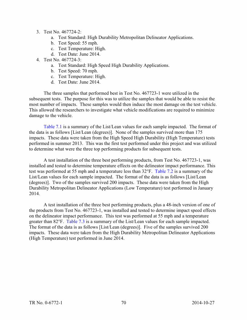
TR No. 0-6772-1 70 2014-10-27
3. Test No. 467724-2: a. Test Standard: High Durability Metropolitan Delineator Applications. b. Test Speed: 55 mph. c. Test Temperature: High. d. Test Date: June 2014.
4. Test No. 467724-3: a. Test Standard: High Speed High Durability Applications. b. Test Speed: 70 mph. c. Test Temperature: High. d. Test Date: June 2014.
The three samples that performed best in Test No. 467723-1 were utilized in the
subsequent tests. The purpose for this was to utilize the samples that would be able to resist the most number of impacts. These samples would then induce the most damage on the test vehicle. This allowed the researchers to investigate what vehicle modifications are required to minimize damage to the vehicle.
Table 7.1 is a summary of the List/Lean values for each sample impacted. The format of the data is as follows [List/Lean (degrees)]. None of the samples survived more than 175 impacts. These data were taken from the High Speed High Durability (High Temperature) tests performed in summer 2013. This was the first test performed under this project and was utilized to determine what were the three top performing products for subsequent tests.
A test installation of the three best performing products, from Test No. 467723-1, was installed and tested to determine temperature effects on the delineator impact performance. This test was performed at 55 mph and a temperature less than 32°F. Table 7.2 is a summary of the List/Lean values for each sample impacted. The format of the data is as follows [List/Lean (degrees)]. Two of the samples survived 200 impacts. These data were taken from the High Durability Metropolitan Delineator Applications (Low Temperature) test performed in January 2014.
A test installation of the three best performing products, plus a 48-inch version of one of the products from Test No. 467723-1, was installed and tested to determine impact speed effects on the delineator impact performance. This test was performed at 55 mph and a temperature greater than 82°F. Table 7.3 is a summary of the List/Lean values for each sample impacted. The format of the data is as follows [List/Lean (degrees)]. Five of the samples survived 200 impacts. These data were taken from the High Durability Metropolitan Delineator Applications (High Temperature) test performed in June 2014.

TR No. 0-6772-1 71 2014-10-27
Table 7.1. Test Sample List/Lean Summary for Test No. 467723-1 (Summer 2013).
Table 7.2. Test Sample List/Lean Summary for Test No. 467724-1 (January 2014).
Delineator #
List Lean List Lean List Lean List Lean List Lean List Lean
1T 90 90 89 89
1B 88 90 88 87 89 89
2T 90 90 88 90
2B 90 86 90 86
3T 89 90 88 90
3B 90 88 90 88
4T 89 90 88 89 86 86
4B 89 86 89 86
5T 89 89 89 89 89 86 86 86 85 86
5B 87 90 87 90 87 86
6T 89 89 88 90 87 86 87 86 86 85
6B 89 89 89 89
7T 89 90 87 88
7B 89 90
Before Run #1 Run #50 Run #100 Run #150 Run #200
Failed After Impact #1
Failed After Impact #16
Failed After Impact #5
Failed After Impact #48
Failed After Impact #3
Failed After #175
Failed After Impact #46
Failed After Impact #17
Failed After Impact #6
Failed After Impact #56
Failed After #175
Failed After Impact #59
Failed After Impact #57 - > 15 deg
Failed After Impact #57 - Bolt Pulled out of Delineator Base
Delineator #
List Lean List Lean List Lean List Lean List Lean List Lean
1T 89 89 87 87 86 86
1B 90 90 88 90 87 89 87 89 87 89
2T 90 89 87 87 85 86 83 87
2B 89 89 86 90 86 89 85 89 83 89
3T 90 87 87 87 85 87
3B 90 90 88 90 88 89 89 89
4T 89 89 89 87 87 86 84 85
4B 89 90 87 90 86 89 85 88
5T 89 89 89 87 88 88 89 86
5B 89 89 90 90 89 89 90 89 89 89 89 89
6T 89 90 90 88 89 88 89 87 89 89
6B 89 90 89 89 89 89 89 89 89 89 89 89
9T 87 88 88 88
9B 90 90 90 89
Before Run #10 Run #50 Run #100 Run #150 Run #200

TR No. 0-6772-1 72 2014-10-27
Table 7.3. Test Sample List/Lean Summary for Test No. 467724-2 (June 2014 – 55 mph).
A test installation identical to Test No. 467724-2 was installed and tested to determine impact speed effects on delineator performance. This test was also performed in an attempt to duplicate the results of the Test No. 467723-1, to help determine repeatability of the delineator performance. This test was performed at 70 mph and a temperature greater than 82°. Table 7.4 is a summary of the List/Lean values for each sample impacted. The format of the data is as follows [List/Lean (degrees)]. Two of the samples survived 200 impacts. These data were taken from the High Speed High Durability Delineator Applications (High Temperature) test performed in June 2014.
Delineator #
List Lean List Lean List Lean List Lean List Lean List Lean
1T 89 90 90 90 89 88 89 88 88 88 89 87
1B 89 90 90 89 89 87 89 87 89 87 89 86
2T 89 90 90 89 89 88 89 88 89 88 88 88
2B 90 90 90 90 89 87
3T 90 90 90 88 89 88 88 87 88 87 87 88
3B 90 90 89 89 89 88 90 87 90 87
4T 90 90 89 89 89 88 88 87 89 87 89 87
4B 90 90 90 88 89 87
5T 90 90 90 90
5B 90 90 89 88 89 86 89 85 89 85
6T 89 88 88 88
6B 89 89 89 89 88 81 89 87
7T 88 88 89 89
7B 89 90 89 89
8T 89 90 89 90
8B 89 88 89 88 90 86
9T 90 88 89 89 89 89 90 90 90 89
9B 90 88 89 90
Before Run #1 Run #50 Run #100 Run #150 Run #200
Failed on Impact #41 - > 15 deg
Failed on Impact #20 - > 15 deg
Failed on Impact #32 - > 15 deg
Failed on Impact #8 - Pulled Out of Base
Failed on Impact #17 - > 15 deg
Failed on Impact #8 - > 15 deg - Ruptured on Impact #40
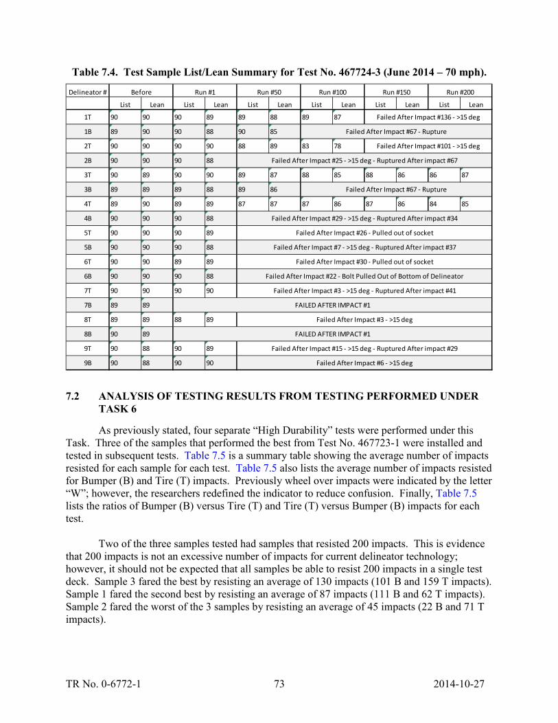
TR No. 0-6772-1 73 2014-10-27
Table 7.4. Test Sample List/Lean Summary for Test No. 467724-3 (June 2014 – 70 mph).
7.2 ANALYSIS OF TESTING RESULTS FROM TESTING PERFORMED UNDER TASK 6
As previously stated, four separate “High Durability” tests were performed under this Task. Three of the samples that performed the best from Test No. 467723-1 were installed and tested in subsequent tests. Table 7.5 is a summary table showing the average number of impacts resisted for each sample for each test. Table 7.5 also lists the average number of impacts resisted for Bumper (B) and Tire (T) impacts. Previously wheel over impacts were indicated by the letter “W”; however, the researchers redefined the indicator to reduce confusion. Finally, Table 7.5 lists the ratios of Bumper (B) versus Tire (T) and Tire (T) versus Bumper (B) impacts for each test.
Two of the three samples tested had samples that resisted 200 impacts. This is evidence that 200 impacts is not an excessive number of impacts for current delineator technology; however, it should not be expected that all samples be able to resist 200 impacts in a single test deck. Sample 3 fared the best by resisting an average of 130 impacts (101 B and 159 T impacts). Sample 1 fared the second best by resisting an average of 87 impacts (111 B and 62 T impacts). Sample 2 fared the worst of the 3 samples by resisting an average of 45 impacts (22 B and 71 T impacts).
Delineator #
List Lean List Lean List Lean List Lean List Lean List Lean
1T 90 90 90 89 89 88 89 87
1B 89 90 90 88 90 85
2T 90 90 90 90 88 89 83 78
2B 90 90 90 88
3T 90 89 90 90 89 87 88 85 88 86 86 87
3B 89 89 89 88 89 86
4T 89 90 89 89 87 87 87 86 87 86 84 85
4B 90 90 90 88
5T 90 90 90 89
5B 90 90 90 88
6T 90 90 89 89
6B 90 90 90 88
7T 90 90 90 90
7B 89 89
8T 89 89 88 89
8B 90 89
9T 90 88 90 89
9B 90 88 90 90
Failed After Impact #22 - Bolt Pulled Out of Bottom of Delineator
Failed After Impact #3 - >15 deg - Ruptured After impact #41
Failed After Impact #3 - >15 deg
Failed After Impact #25 - >15 deg - Ruptured After impact #67
Failed After Impact #29 - >15 deg - Ruptured After impact #34
Failed After Impact #26 - Pulled out of socket
Failed After Impact #7 - >15 deg - Ruptured After impact #37
Failed After Impact #30 - Pulled out of socket
Before Run #1 Run #50 Run #100 Run #150 Run #200
Failed After Impact #15 - >15 deg - Ruptured After impact #29
Failed After Impact #6 - >15 deg
Failed After Impact #67 - Rupture
Failed After Impact #67 - Rupture
Failed After Impact #136 - >15 deg
Failed After Impact #101 - >15 deg
FAILED AFTER IMPACT #1
FAILED AFTER IMPACT #1

TR No. 0-6772-1 74 2014-10-27
Table 7.5. Average Number of Impacts Resisted.
In almost all warm weather tests the delineators subjected to a tire impact fared better than the bumper impacts; however, in the cold weather testing, the bumper impacts fared better than tire impacts by 30 percent for all samples. This is evidence that both bumper and tire impacts are critical, depending on the impact and environmental conditions, and should be considered in future testing.
Table 7.6 is a summary table showing relationships between different test conditions for each sample. The first column is a comparison showing impact speed effects on delineator performance. This column shows that there is a significant and consistent increase in delineator performance as the impact speed is lowered; however, the relationship is not uniform. For this
2013 2014 2014 2014High Low High High
70 55 55 70
T and B 32 177.25 88.75 21.25
B 57 200 147 14.5
T 7 154.5 30.5 28
B/T - T/B 8.1 - 0.1 1.3 - 0.8 4.8 - 0.2 0.5 - 1.9
T and B 30.5 35.5 105 10.5
B 5 44 32 6
T 56 33 178 15
B/T - T/B 0.1 - 11.2 1.3 - 0.8 0.2 - 5.6 0.4 - 2.5
T and B 114.25 126.13 168 103.13
B 53.5 142.75 137.75 47
T 175 109.5 200 159.25
B/T - T/B 0.3 - 3.3 1.3 - 0.8 0.7 - 1.5 0.3 - 3.4
Year
Sam
ple
#3
TempSpeed (mph)
Sam
ple
#1Sa
mpl
e #2

TR No. 0-6772-1 75 2014-10-27
reason a high speed test can be considered conservative over a low speed test; however, there is no consistent way of predicting the results of one given the results of another.
Table 7.6. Test Sample Performance Comparison Chart.
Column two shows that there is an inconsistent relationship between temperature and delineator performance. This relationship is probably due to the different properties of the plastics used to manufacture the products. Some plastics will fare better in cold climates, while others will fare better in warmer climates.
Column three shows the repeatability of performance of delineators given a specific set of impact conditions. If Samples 1 and 2 are considered, there does not appear to be a clear relationship between the two test samples. That being said, Sample 3 shows a clear relationship between the consecutive tests. The researchers believe this variance can be described by a few different factors. First, the number of samples installed for #1 and #2 was significantly less than that of #3. Only 2 representative samples of #1 and #2 were installed in the 2013 test, where 4 samples of #3 were installed. Again, only 2 samples of #2, 4 samples of #1, and 8 samples of #3 were installed in the 2014 test. Second, the failure mode of sample #1 was inconsistent. Many times the failure mode was a failure of the product to right itself after an impact (list/lean > 15°). In this case, the delineator was in general undamaged; however, due to its specific construction,
2013 / 2014High Low / High High
55 / 70 55 70
T and B4.18 2.00 1.51
B10.14 1.36 3.93
T1.09 5.07 0.25
T and B10.00 0.34 2.90
B5.33 1.38 0.83
T11.87 0.19 3.73
T and B1.63 0.75 1.11
B2.93 1.04 1.14
T1.26 0.55 1.10
Year 2014Temp
Speed (mph)Sa
mpl
e #1
Sam
ple
#2Sa
mpl
e #3

TR No. 0-6772-1 76 2014-10-27
it could not right itself on occasion, only to later right itself after a few more impacts. This failure mode seems to be less consistent than observed failures in others and may explain some of the variance in test results. Finally, Sample #1 tended to unscrew randomly, which significantly varied the performance of the delineator.
For these primary reasons, it is believed that the comparison should be based primarily on Sample #3. Sample #3 shows that the performance of the delineator was repeated within 10-15 percent. The researchers believe this to be an acceptable variance in performance, given the small number of samples and slight variance in impact conditions. This is evidence that the impact vehicle modifications and the induced damage to the impacting vehicle present a reasonably repeatable impact condition that will produce repeatable delineator performance results.
7.3 IMPACT VEHICLE DAMAGE AND UPDATED VEHICLE MODIFICATIONS
Throughout testing, the damage to the lower bumper shell was found to be inconsistent. Under some conditions (cold weather 55 mph impact), the bumper shell was never damaged, even after 200 impacts. In other cases, the bottom shell of the bumper was damaged after the first impact. Some of this is believed to be due to variances in the plastic bumper itself. The performance of the pipe support bumper was however undamaged or unchanged throughout testing.
Figure 7.1 shows a series of images detailing a comparison of bumper shell damage after completion of each of the tests performed under this Task. Notice that with the exception of the cold weather testing (Test No. 467724-1), the damage to the bumper was comparable. Given the results shown in Table 7.4, it is the opinion of researchers that the failure of the bottom of the bumper shell was not a significant factor on delineator performance when a pipe bumper support is installed. It is the recommendation that this method of supporting the bumper become the standard method of bumper modifications in all future tests. This method provides a realistic and repeatable method for impacting delineators in excess of 200 times.
Two different failure modes of the headlamp were witnessed during the impact testing of delineators. The first was the failure of the lens itself due to repeated delineator impacts. The second was the failure of the mounting points for the headlamp. In this case, the intact headlamp was ripped from the vehicle by the repeated delineator impacts. Images of both failure modes can be found in Figure 7.2. The researchers felt this was a significant change in the geometry of the impacting vehicle and felt that this problem needed to be addressed to prevent it from occurring in future testing.
TR No. 0-6772-1 77 2014-10-27
467723-1 467724-1
467724-2 467724-3
Figure 7.1. Bumper Shell Damage Comparison.
Broken Headlight Missing Headlight
Figure 7.2. Headlamp Damage.
Two separate methods of headlamp modifications were utilized to prevent witnessed
failure modes. To address the lens failure mode, the headlamps were removed and filled with expanding foam as shown in Figure 7.3. This supported the lens from the inside preventing the

TR No. 0-6772-1 78 2014-10-27
lens from fracturing. This solved the fracture problem; however, in later testing the intact headlamp was knocked free of its supports by the impacting delineator. The headlamp was first replaced using its original mounting screws, but the failure mode repeated itself. To address this issue, the headlamp was secured to the body and bumper shell using a layer of black “Gorilla Tape®.” An image of the modification can be found in Figure 7.3. The use of the layer of “Gorilla Tape” did not seem to affect the performance of the delineator impacted by the tire. It is the recommendation that these two methods of modifications be utilized in all future testing to provide a consistent and repeatable impact test.
Foam Filled Secured With “Gorilla Tape®”
Figure 7.3. Headlamp Modifications.
During testing there seemed to be a varying degree of hood damage to the vehicle. Most of the damage was limited to some significant deformation where the delineators impacted. In some rare cases, the hood actually succumbs to low cycle fatigue at the end of the delineator impact zone. The damage to the hood seemed to be more severe in lower speed tests than in higher speed tests. The researchers believe this is because the vehicle was subjected to a greater number of impacts in the lower speed tests, because the delineators were resisting far more impacts. As delineator technology advances, it is expected that more damage will be witnessed in the higher speed impacts as delineator are able to resist more impacts. Figure 7.4 shows examples of the damages witnessed during impact testing under this task.
While the damage to the hood was significant, it did not seem to change the performance
of the delineator. The researchers did investigate possible methods of strengthening the hood. The researchers took the strict stance that they did not want to change the surface of the hood or change its deflection characteristics significantly. The researchers did not want to stiffen the hood too much for fear of making the simulated impact too severe when compared to a “real world” impact. Upon investigation, the researchers found that most of the supporting structure under the hood in the front of the vehicle was made from plastic. This, coupled with the tight spaces under the hood, makes creating a support structure (similar to the bumper modification) very problematic. One idea that was tested includes filling voids within the hood with expanding foam (fire resistant), as shown in Figure 7.5. While this did seem to help the performance of the hood, the researchers are not sure the minor added capacity is worth the cost of using the foam.

TR No. 0-6772-1 79 2014-10-27
Deformation of Hood Tear in Hood
Figure 7.4. Hood Damage.
Figure 7.5. Hood Modification.
At this time, the researchers suggest using the hood unmodified with the foam installation
being optional. The researchers believe that over time the testing labs will be able to find what will work best for them. The researchers still strongly believe that the impact vehicle hood deflection characteristics should be similar to an undamaged hood from the original equipment manufacturer (OEM). The researchers also believe that the hood should come in direct contact with the delineator since surface friction plays a key role in delineator performance (especially in bumper impact condition). A flat paint finish does not appear to have a different performance compared to a glossy finish according to the result comparison between Test No. 467723-1 and Test No. 467724-3 (High Speed/High Temperature).

TR No. 0-6772-1 81 2014-10-27
CHAPTER 8. SUMMARY AND CONCLUSIONS
The objective of this project was to develop a new test method for evaluating the impact performance of delineators for given applications. The researchers focused on developing a test method that was reproducible and attempted to reproduce failure modes witnessed through field observations. The researchers also attempted to optimize the testing standard to minimize the cost and effort to evaluate the products. The researchers feel that the process was successful and a balanced testing standard, meeting all requirements, has been developed.
8.1 IMPACT DURABILITY STANDARD CLASSES
Originally, four durability classes were suggested (Low Durability, High Durability, Low Speed Heavy Vehicle Traversals, and Low Speed High Angle). After preliminary testing and evaluation, it quickly became clear that the two low-speed test classes (Low Speed Heavy Vehicle Traversals and Low Speed High Angle) resulted in the same results; however, the low-speed tests required significantly more impacts to obtain the same failure modes. For this reason, the recommendation of the researchers was that the low-speed tests not be considered for future testing. Additionally, the researchers recommended that an additional testing class be added to the list of classes (High Durability Metropolitan Delineator Applications). This new standard was geared more toward evaluating delineators for lower speed, inner city applications.
8.2 IMPACT CONDITIONS
This project set out to extensively test and evaluate the effect of varying impact conditions, such as impact speed and ambient temperature. After completion of testing and evaluation, the researchers noted a significant effect of impact speed and ambient temperature. It was documented that an increase in impact speed would significantly decrease the durability of a delineator. Ambient temperature has a significant effect on the durability of a delineator; however, this effect does not have a consistent relationship between different products. Some products performed better at low temperatures, while others performed better at higher temperatures. Future testing standards should take this into account when evaluating delineator samples.
8.3 VEHICLE MODIFICATIONS
This project documented the impact of a single vehicle more times than any other vehicle has been impacted. This vehicle is still viable and will be utilized in the future testing of manufacturer-sponsored testing for TxDOT acceptance. This exceptional performance was mostly due to the moderate vehicle modifications that allow the vehicle such a high number of impacts without significant damage to the impacting vehicle. These modifications also allowed the vehicle profile to remain almost unchanged from the first impact to last.
The first recommended modification was the inclusion of the bumper support structure. This structure prevents major changes in the bumper profile from the first impact to the last. The second recommended modification included changes to the headlamp assembly. To prevent fracture of the headlamp assembly, the researchers recommended that the headlamp be filled

TR No. 0-6772-1 82 2014-10-27
with expanding foam. In addition, the researchers recommended that the headlamp be secured to the vehicle using Gorilla Tape.
8.4 LIST AND LEAN
Previously, the primary method for evaluating whether a delineator could restore to a vertical orientation was to measure list and lean. List is how far the delineator slopes left or right when compared to the path of the vehicle. Lean is how far the delineator slopes toward or away from the impacting vehicle. In existing standards, it is unclear exactly how to measure the angle of the delineator as the delineator naturally curves. Figure 8.1 shows a standard method for measuring List/Lean and curvature offset recommended by the researchers. The Curvature Offset is measured at the maximum offset in inches.
Testing and evaluation under this project showed that list and lean generally remained
unchanged throughout testing until just before failure. The researchers noted that a delineator would fail soon after reaching a list or lean greater than 15°. For this reason, the researchers recommend a maximum angle (in any direction) of 15°.
Figure 8.1. Diagram of Measurement Methods.
8.4 TESTING FACILITIES
The recommendation of the researchers is that the testing be performed by an International Standards Organization (ISO) 17025 accredited lab. This would follow the example set by FHWA in the implementation of AASHTO MASH. This would become a requirement should this standard be adapted into an ASTM standard.

TR No. 0-6772-1 83 2014-10-27
8.5 RECOMMENDED TESTING SPECIFICATION
1. Generic Test Specifications. a. Impact Vehicle: Modified MASH 1100C (small sedan – within 10 year models). b. Impact Velocity: Varies.
i. Low Durability Side of Roadway Applications (55 mph) – Maximum of 10 impacts.
ii. High Durability Metropolitan Delineator Applications (55 mph). iii. High Speed High Durability Applications (70 mph).
c. Total Number of Test Samples: 16 delineator posts and 8 bases (8 hot and 8 cold).
d. Hot Test Temp: 82°F or greater. e. Cold Test Temp: 35°F or lower. f. Manufacturer-suggested maximum installed height of delineator shall be tested.
2. Test Installation. a. Two rows of four delineators. b. One row will be aligned with vehicle tire (wheel over impact). c. One row will be aligned with the opposing vehicle quarter point (bumper impact). d. Each delineator will be spaced a minimum of 50 inches (or 2 inches greater than
delineator height) from a subsequent delineator to prevent interaction. e. Half of the bumper and wheel over impacts will be oriented parallel to the path of
the impacting vehicle. f. Half of the bumper and wheel over impacts will be oriented 25° from the path of
the impacting vehicle. 3. Surface Attachment Method.
a. All testing will be performed with the intended product (no substitutions). b. Material/technical specifications must be submitted with each product. c. At least four delineators must be attached with each type of proposed attachment
method: i. At least two of each method must be a bumper impact.
ii. At least two of each method must be a wheel over impact. iii. An equal number of bumper and wheel over impacts will be performed on
each method. d. If more than two attachment methods are proposed:
i. Number of samples tested at one time can be increased at the testing facility’s discretion.
ii. Testing may be repeated with a new set of 4 or more delineator samples to qualify untested methods.
4. Documentation. a. Material classification data shall be submitted with test samples (to be retained by
testing lab). ASTM D5630 (Ash Testing) and Fourier Transform Infrared Spectrometry (FTIR) ASTM E168 and E1252 are preferred methods.
b. Material/technical specifications shall be submitted with test samples (to be included in report).
c. Complete fabrication drawings detailing all component dimensions and thicknesses shall be submitted with test samples (to be retained by testing lab).
d. General drawings shall be submitted with test samples (to be included in report).

TR No. 0-6772-1 84 2014-10-27
e. Detailed instructions for installation shall be submitted for each attachment method to be tested.
f. Two additional randomly selected samples shall be submitted for potential destructive testing to verify the documentation information submitted is accurate.
g. All tests will be videotaped using standard frame rate. A counter showing impact number should be in view of the standard rate camera during testing.
h. List of minimum photos to be taken. i. Photo of Counter showing impact number.
ii. Photos of system. 1. Longitudinal. 2. Perpendicular. 3. Oblique.
iii. Delineator. 1. Photo of identifying label for test sample. 2. Frontal face of delineator. 3. Any damage to delineator. 4. Close up shot of reflective sheeting to document damage.
iv. Photo of impacting vehicle. 1. Frontal. 2. Perpendicular (wheel over side). 3. Oblique.
v. When to be taken. 1. Prior to testing. 2. After first impact. 3. After 5th impact. 4. After 10th impact. 5. After 20th impact. 6. After 50th impact. 7. After 100th impact. 8. After 150th impact. 9. After 200th impact.
i. Written documentation. i. Measure list and lean.
1. Prior to testing. 2. After first impact. 3. After 10th impact 4. After 100th impact 5. After 200th impact.
ii. Document any damage to delineator. iii. Document any failures and on what impact they occurred. iv. Failure of delineator to self-restore to within 15° of vertical in any
direction. 1. Measurement will be taken within 5 minutes last impact. 2. Testing will be postponed until either all samples are deemed
within 15° of vertical or the suspect sample is deemed failed.

TR No. 0-6772-1 85 2014-10-27
5. Testing. a. All impacts will be in the same direction of travel. b. Hot temperature impacts.
i. Only fresh untested samples will be used. ii. Bases may be reused at the discretion of manufacturer and testing lab.
iii. All 200 impacts will be performed on the same samples. iv. All 200 impacts will occur at a temperature greater than 82°F. v. Hot temp testing will be qualified separately than cold temp testing.
c. Cold temperature impacts. i. Only fresh untested samples will be used.
ii. Bases may be reused at the discretion of manufacturer and testing lab. iii. All 200 impacts will be performed on the same samples. iv. All 200 impacts will occur at a temperature less than 35°F. v. Cold temp testing will be qualified separately than hot temp testing.
6. Evaluation of Testing. a. If a representative attachment method fails prematurely.
i. The attachment method can be reevaluated only once. ii. A full installation of eight samples of the failed method must be tested.
iii. This method will be qualified separately from all other attachment methods.
b. Samples are considered to have failed if they do not self-restore to within 15° from vertical within 5 minutes of being impacted.
7. Reported Values. a. Number of impacts resisted by each sample. b. Average number of impacts resisted for each surface attachment method.
i. Average number of tire impacts resisted. ii. Average number of bumper impacts resisted.
iii. Average number of impacts resisted. c. Average number of impacts resisted (all samples).
i. Average number of tire impacts resisted. ii. Average number of bumper impacts resisted.
iii. Average number of impacts resisted. d. Table of images for each delineator as shown in Table 6.5.


TR No. 0-6772-1 87 2014-10-27
CHAPTER 9. IMPLEMENTATION
The implementation of this research should be staged. This would allow for the districts, manufacturers, and testing labs to make required adjustments.
The first stage should include developing the recommended test specification into a
TxDOT official specification. It is recommended that the Material and Testing Division or Traffic Division host this standard. TTI researchers could help with the writing of this standard. This would give an official testing standard for use by approved testing labs. Once the standard is implemented, the manufacturers could start testing. In addition to the development of a state specification, an ASTM specification should be pursued.
The second stage should include a sunset rule on the acceptance of products tested using
previously accepted methods. This would provide an incentive for manufacturers and districts to begin using the new standard.
The third stage should include the process of reevaluating current delineator installations
to determine if more suitable products should be installed to reduce current maintenance costs. This should be a gradual process.
In addition to the implementation of this standard, a research project should be funded to develop a standard design manual for the layout, testing, and selection of delineators. This was one of the consistent responses from the survey of the TxDOT districts. While this was a very valid concern, it did not fall under the scope of work for this project, and therefore was not addressed.
The proposed manual should combine this work with the work performed under Project
0-6643-1. Project 0-6643-1 was primarily focused on the layout of delineator systems to reduce impacts, while the current project was focused on evaluating the durability of a delineator system. This still leaves one part of the design process unanswered. The district engineers still need guidance on when delineators are needed, what the dimensions of the delineator should be, and how they should be installed (just to name a few). The manual would also give guidance as to which durability class described in this standard is applicable for the installation being designed. This research would utilize the work from both of the aforementioned projects and combine them with some additional research to give a comprehensive design manual for the selection and use of delineators.


TR No. 0-6772-1 89 2014-10-27
REFERENCES
1 Manual for Uniform Traffic Control Devices (MUTCD), Federal Highway
Administration, U. S. Department of Transportation, Washington, D.C., 2012. 2 Manual for Assessing Safety Hardware. American Association of State Highway and
Transportation Officials, Washington, D.C., 2009. 3 Section 993 Object Markers And Delineators, Florida Department of Transportation,
State Specifications Office, July 23, 2013. 4 Ross, H. E., D. L. Sicking, R. A. Zimmer, and J. D. Michie. Recommended
Procedures for the Safety Performance Evaluation. National Cooperative Highway Research Program Report 350. National Academy Press, Washington, D.C., 1993.
5 S.P. Kuchangi, R.J. Benz, A.A. Nelson, A.P. Voigt, R. Stevens, J.P. Wikander, L. Theiss, Guidance for Effective Use of Pylons for Lane Separation on Preferential Lanes and Freeway Ramps, Report No. 0-6643-1, Texas A&M Transportation Institute, College Station, TX, May 2013.
6 NTPEP TTCD Testing Plan: http://www.ntpep.org/Documents/Technical_Committee/TTCD/Work%20Plans/TTCD%20Work%20Plan.pdf, Last accessed 2014-08-13.
7 National Oceanic and Atmospheric Administration (NOAA), http://www.ncdc.noaa.gov/temp-and-precip/, last accessed 2013-02-05.
8 http://sports.racer.net/docs/rules/2002/sect_18_roll_cage_and_chassis_2002_gcr.pdf, last accessed 2013-03-07.


TR No. 0-6772-1 91 2014-10-27
APPENDIX A. DETAILS OF THE MODIFIED BUMPER SHELL FOR 1100C VEHICLE.

TR No. 0-6772-1 92 2014-10-27

TR No. 0-6772-1 93 2014-10-27

TR No. 0-6772-1 94 2014-10-27

TR No. 0-6772-12-1 95 2014-10-27
APPENDIX B. ROAD BASE DETAILS
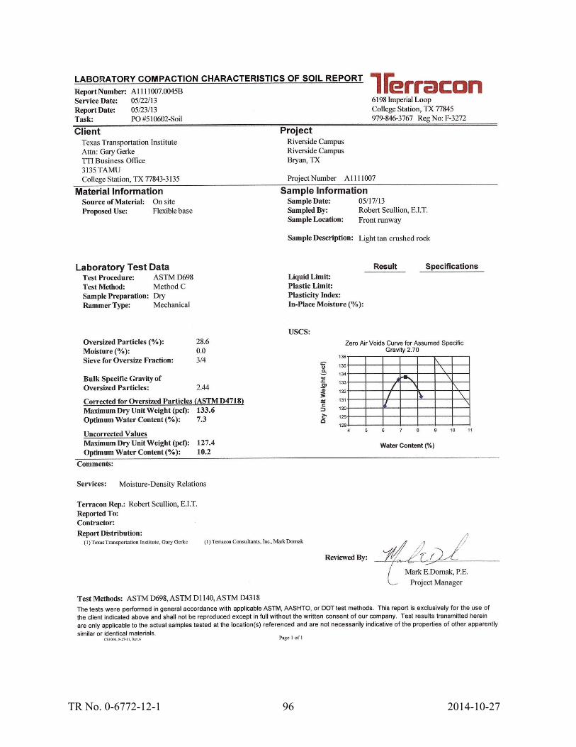
TR No. 0-6772-12-1 96 2014-10-27