development of guide for selection of …...development of guide for selection of substructure for...
TRANSCRIPT
DEVELOPMENT OF GUIDE FOR SELECTION OF
SUBSTRUCTURE FOR ABC PROJECTS
Submitted by:
PIs - Armin Mehrabi, Hesham Ali
Graduate Student - Mohamadtaqi Baqersad
Department of Civil and Environmental Engineering
Florida International University
Miami, FL
Submitted to:
ABC-UTC
Florida International University
Miami
August 2019

Table of Contents 1 Introduction ................................................................................................................. 1
1.1 Background .......................................................................................................... 1
1.2 Intended Users ...................................................................................................... 2
1.3 Guideline Organization ........................................................................................ 3
1.4 How to Use the Guideline .................................................................................... 4
2 ABC – Definitions and descriptions ........................................................................... 6
2.1 ABC Bridge Components .................................................................................... 6
2.1.1 Superstructure ............................................................................................... 6
2.1.1.1 Deck Panels ........................................................................................... 7
2.1.1.2 Girders ................................................................................................. 12
2.1.1.3 Barriers and railing .............................................................................. 14
2.1.1.4 Miscellaneous elements ....................................................................... 15
2.1.2 Substructure ................................................................................................ 16
2.1.2.1 Piers ..................................................................................................... 18
2.1.2.2 Abutments ............................................................................................ 19
2.1.2.3 Pier cap ................................................................................................ 22
2.1.3 Foundation .................................................................................................. 24
2.1.3.1 Precast Spread Footing ........................................................................ 24
2.1.3.2 Deep Foundations ................................................................................ 25
2.1.3.3 Pile Cap Footings................................................................................. 27
2.1.3.4 Precast Pier Box Cofferdams ............................................................... 28
2.1.3.5 Precast Sheet Piling ............................................................................. 29
2.1.3.6 Geofoam Rapid Embankment System ................................................. 30
2.1.3.7 Geosynthetic Reinforced Soil (GRS) Integrated Bridge System......... 31
2.1.3.8 Mechanically stabilized earth retaining walls ..................................... 32
2.1.4 Systems and Subsystems............................................................................. 33
2.1.4.1 Modular Superstructure Subsystems ................................................... 34
2.1.4.2 Buried Bridges (20 ft< Span < 70ft) .................................................... 38
2.1.4.3 Culverts ................................................................................................ 43
2.1.5 Joints and Connections ............................................................................... 45
2.1.5.1 Superstructure element connections .................................................... 46

2.1.5.2 Substructure element connections ....................................................... 50
2.1.5.3 Foundation connections ....................................................................... 62
2.1.5.4 Categorizing the bridge connections according to their seismic
performance .......................................................................................................... 68
2.2 Construction methods ......................................................................................... 70
2.3 Potential Issues with Design and Construction .................................................. 75
2.3.1 Superstructure ............................................................................................. 76
2.3.2 Substructure ................................................................................................ 76
2.3.3 Foundation .................................................................................................. 76
2.3.4 Joints and Connections ............................................................................... 76
3 New Bridge Construction ......................................................................................... 78
3.1 Major Parameters Affecting selection of bridge type in general ....................... 83
Environmental considerations ................................................................................... 83
Geometric Considerations ......................................................................................... 83
Site Condition and Accessibility ............................................................................... 84
Design Constraints and Considerations .................................................................... 84
Compatibility between Superstructure and Substructure, and between Substructure
and Foundation.......................................................................................................... 84
3.2 Selection of Construction Method and Type of Superstructure ......................... 85
3.3 Available Selection and Design Considerations for Substructure ..................... 89
3.3.1 Selection of Substructure Elements and Systems ....................................... 91
3.3.2 Parameters affecting the selection of bridge elements and construction
methods in general .................................................................................................... 92
Compatibility of Substructure with Superstructure and Bridge Configuration .... 92
Compatibility of Substructure with Foundation ................................................... 92
3.3.3 Parameters Specific to Substructure ........................................................... 93
3.3.4 Selection of Substructure based on Compatibility with Superstructure and
Substructure-specific Parameters .............................................................................. 93
3.3.5 Suitability of Substructure Types with Respect to Foundation .................. 94
3.4 Selection and Design Considerations for Foundation ...................................... 101
3.5 Design considerations for Connections ............................................................ 101
3.6 Categorization of Bridges based on Bridge Span............................................. 102
3.7 Considerations for superstructure system and elements selection ................... 102
3.8 Considerations for substructure system and elements selection ...................... 105
3.9 Considerations for foundation system and elements selection......................... 105
4 Existing Bridge Replacement ................................................................................. 106
4.1 Type and Design of Existing Foundations ....................................................... 110
4.2 Evaluation of Existing Substructure for Potential Reuse ................................. 110
4.2.1 Concrete Elements Field Testing .............................................................. 112
4.2.2 Field Testing for Steel Elements ............................................................... 114
4.2.3 Structural capacity .................................................................................... 115
4.2.3.1 Modeling and Analysis ...................................................................... 117
4.2.4 Functional adequacy ................................................................................. 118
4.2.5 Integrity and remaining service life .......................................................... 119
4.2.5.1 Integrity of concrete elements ........................................................... 120
4.2.5.2 Integrity of steel elements .................................................................. 122
4.2.6 Hydraulic issues ........................................................................................ 123
4.2.7 Seismic considerations .............................................................................. 124
4.2.8 Other Considerations ................................................................................ 124
4.2.9 Remaining Service Life Analysis ............................................................. 125
4.3 Evaluation of existing foundation for potential reuse ...................................... 125
4.3.1 Structural capacity .................................................................................... 125
NDE .................................................................................................................... 125
Field Testing ....................................................................................................... 125
Modeling and Analysis ....................................................................................... 125
4.3.2 Functional adequacy (width, height, traffic, etc.) ..................................... 125
4.3.3 Integrity and remaining service life .......................................................... 125
4.3.4 Hydraulic issues ........................................................................................ 125
4.3.5 Seismic considerations .............................................................................. 125
4.4 Suitability of Substructure Types with Respect To Superstructure and Bridge
Configuration .............................................................................................................. 125
4.5 Suitability of Foundation Types with Respect To Superstructure/Substructure and
Bridge Configuration .................................................................................................. 126
4.6 Decision Making for Replacement, Reuse, Or Retrofitting/ Strengthening of
Existing Foundations and Substructures ..................................................................... 127
4.6.1 Life Cycle Cost Analysis .......................................................................... 130

4.6.1.1 Basic steps in LCCA.......................................................................... 131
4.6.1.2 Bridge and its elements...................................................................... 131
4.6.1.3 Planning horizon, analysis scenario, and base case ........................... 131
4.6.1.4 Alternative bridge management strategies ........................................ 132
4.6.1.5 Deterioration models and parameters ................................................ 133
4.6.1.6 Cost estimates .................................................................................... 133
4.6.1.7 Present values .................................................................................... 134
4.6.1.8 Sensitivity analysis ............................................................................ 136
4.6.1.9 Preferred strategy ............................................................................... 138
4.6.2 Social Impacts ........................................................................................... 138
4.7 Methods of Retrofitting/ Strengthening ........................................................... 139
4.7.1 Substructure .............................................................................................. 139
4.7.2 Foundation ................................................................................................ 141
4.8 Extension or Amending to the Exiting Substructure and/or Foundation ......... 142
4.8.1 Substructure .............................................................................................. 142
4.8.2 Foundations ............................................................................................... 142
5 Survey ..................................................................................................................... 143
5.1 Survey Participants ........................................................................................... 144
5.2 Survey Results .................................................................................................. 146
5.2.1 ABC Construction Method ....................................................................... 147
5.2.2 Superstructure elements ............................................................................ 147
5.2.3 What is needed to prepare agencies to adopt the ABC Technique? ......... 148
5.2.4 Substructure elements ............................................................................... 148
5.2.5 Foundation Elements ................................................................................ 148
5.2.6 Factors in Selection of Substructure and Foundation Systems ................. 148
5.2.7 Guideline for selection of bridge components .......................................... 149
5.2.8 Interaction Between Superstructure, Substructure, and Foundation in the
Selection of Components ........................................................................................ 149
5.2.9 ABC technology in bridge foundation construction ................................. 149
5.2.10 Seismic Considerations in Design of Foundation and Substructure ......... 149
5.2.11 Issues in Using ABC Technology ............................................................. 150
5.2.12 Decision making procedure in selecting, replacement, reuse, .................. 150
5.2.13 Retrofitting/strengthening ......................................................................... 150

6 Schedule .................................................................................................................. 151
References ....................................................................................................................... 152
APENDIX A ................................................................................................................... 157
Survey Questionnaire .................................................................................................. 157
Note: Highlighted sections are under development by Oklahoma University
Table of Figures Figure 2-1: ABC bridge components .................................................................................. 8
Figure 2-2: ABC bridge elements ....................................................................................... 9
Figure 2-3: Prefabricated deck panel [1] .......................................................................... 10
Figure 2-4: Open grid deck panel [1] ................................................................................ 11
Figure 2-5: Timber deck panels [5] .................................................................................. 11
Figure 2-6: Exodermic deck panel [5] .............................................................................. 12
Figure 2-7: FRP deck panel [5] ......................................................................................... 12
Figure 2-8: Steel girder [9] ............................................................................................... 13
Figure 2-9: Different shape of precast girders [8] ............................................................ 14
Figure 2-10: Deck panel with a barrier [1] Figure 2-11: Deck panel with barrier
[11] .................................................................................................................................... 15
Figure 2-12: Bridge bearing [1] ........................................................................................ 16
Figure 2-13: Substructure elements .................................................................................. 16
Figure 2-14: Prefabricated pier bent [1] ............................................................................ 18
Figure 2-15: Wall Pier [1] ................................................................................................. 19
Figure 2-16: Semi-integral abutment [1] .......................................................................... 20
Figure 2-17: Prefabricated integral abutment [1] .............................................................. 21
Figure 2-18: Prefabricated cantilever abutment [1] .......................................................... 21
Figure 2-19: Prefabricated cantilever wing wall [1] ......................................................... 22
Figure 2-20: Typical type of pier cap [19] ........................................................................ 22
Figure 2-21: Rectangular pier cap [19] ............................................................................. 23
Figure 2-22: Inverted-tee pier cap [19] ............................................................................. 23
Figure 2-23: Inverted-tee pier cap [20] ............................................................................. 24
Figure 2-24 Precast spread footing as bridge foundation [1] ............................................ 25
Figure 2-25 Driven pile (prestressed concrete) as bridge foundation [21] ....................... 26
Figure 2-26 Drilled shaft piles as bridge foundation [26]................................................. 27
Figure 2-27 Continuous flight Auger pile as bridge foundation [1] ................................. 27
Figure 2-28: Prefabricated pile cap footing [1] ................................................................. 28
Figure 2-29: Precast concrete pier box cofferdam [1] ...................................................... 29
Figure 2-30: EPS Geofoam Embankment (Source ACH Foam Technologies) ................ 31
Figure 2-31: Typical Section of a GRS/IBS Bridge abutment [1] .................................... 32
Figure 2-32: Typical Mechanically Stabilized Earth Systems (MSE) Wall Details [1] ... 32
Figure 2-33: Modular steel superstructure system [1] ...................................................... 36
Figure 2-34: Modular steel girder; I-beams (left) [1], Folded plate (right) [29] ............... 36
Figure 2-35: Modular orthotropic superstructure system [1] ............................................ 37
Figure 2-36: Modular double tee superstructure system [1] ............................................. 37
Figure 2-37: Laminated timber deck system [1] ............................................................... 37
Figure 2-38; Buried Bridge Structure Geometry [31] ....................................................... 38
Figure 2-39: Rectangular (box) buried bridge [31] ........................................................... 40
Figure 2-40: Three-sided buried bridge [31] .................................................................... 40
Figure 2-41: Arch System[31] .......................................................................................... 41
Figure 2-42: Arch buried bridge[31]................................................................................. 41
Figure 2-43: Corrugated Metal Arch buried bridges [31] ................................................. 42
Figure 2-44: High Profile Arch buried bridges [31] ......................................................... 43
Figure 2-45: Example of metal corrugated box [31] ........................................................ 43
Figure 2-46: Precast box culvert section [12] ................................................................... 44
Figure 2-47: Arch culvert [1] ............................................................................................ 44
Figure 2-48: Prefabricated bridge connections [2] ........................................................... 45
Figure 2-49: Examples of deck closure joints [2] ............................................................. 47
Figure 2-50: Non-grouted panel to panel (male-to-female) joint [37, 5] .......................... 47
Figure 2-51: Various type of female-to-female joint [37] ................................................ 48
Figure 2-52: Longitudinal reinforcement [37] .................................................................. 48
Figure 2-53: Panel to girder connection detail [37] .......................................................... 49
Figure 2-54: Leveling bolt [3]........................................................................................... 50
Figure 2-55: Column to cap beam connection using grouted sleeve method [5] ............. 52
Figure 2-56: Precast cap beam and cast-in-place column using grouted pocket [2] ........ 53
Figure 2-57: a) Seismic and b) non-seismic detail of UHPC connection of precast column
and precast cap beam [40] ................................................................................................. 53
Figure 2-58: Grouted sleeve connection between footing and column [2] ....................... 55
Figure 2-59: Cast-in-place footing to precast column connection using mechanical couplers
[2] ...................................................................................................................................... 56
Figure 2-60: Pocket connection of footing and column [18] ............................................ 57
Figure 2-61: Column to column connection [2] ............................................................... 57
Figure 2-62: Closure pour connection in abutment [42] ................................................... 59
Figure 2-63: Precast abutment stem to precast footing connection [2, 42] ...................... 59
Figure 2-64: Grouted couplers connection in prefabricated abutment [42] ...................... 60
Figure 2-65: Abutment connection [2] ............................................................................. 60
Figure 2-66: Precast integral abutment connection to steel pile [2] ................................. 61
Figure 2-67: Precast integral abutment connection to steel pile [2] ................................. 61
Figure 2-68: Steel bar dowels connection in abutment ..................................................... 62
Figure 2-69: Adjacent abutment segments connection [2] ............................................... 62
Figure 2-70 Details of Precast footing to subgrade Connection [2] ................................. 63
Figure 2-71 Precast concrete footing to precast concrete footing connection [2] ............ 64
Figure 2-72 Installation of a precast concrete footing with grouted shear connection on
concrete sub-footing [2] .................................................................................................... 64
Figure 2-73 Connection between precast concrete footing and steel pile with uplift ....... 65
Figure 2-74 Connection details between concrete square pile and pile cap [2] ................ 66
Figure 2-75 Connection between concrete square piles using splice ............................... 67
Figure 2-76 Footing Reinforcing Placement in Providence River Bridge Pier Box......... 68
Figure 2-77: Connection locations based on prefabricated members plastic hinge zone [35]
........................................................................................................................................... 69
Figure 2-78: Connection locations based on their seismic performance [35] .................. 69
Figure 2-79: SPMTs configuration [1] ............................................................................. 71
Figure 2-80: SPMTs bridge move [1] ............................................................................... 71
Figure 2-81: Longitudinal launching construction method [1] ......................................... 72
Figure 2-82: Lateral bridge sliding [1] .............................................................................. 72
Figure 2-83: Jack lifting of the bridge [1] ......................................................................... 73
Figure 2-84: Vertical axis pivot [1] .................................................................................. 73
Figure 2-85: Transverse gantry bridge placement [1]....................................................... 74
Figure 2-86: Longitudinal gantry bridge placement [1] ................................................... 74
Figure 2-87: Bridge placement using conventional cranes ............................................... 75
Figure 3-1: Decision-making flowchart to use prefabricated elements in bridge
construction [52] ............................................................................................................... 80
Figure 3-2: WisDOT ABC decision-making matrix [53] ................................................. 81
Figure 3-3: WisDOT decision-making Flowchart [53] .................................................... 82
Figure 3-4: Parameters affecting selection of ABC components ...................................... 85
Figure 3-5: Decision flowchart for superstructure construction over the roadways [1] ... 87
Figure 3-6: Decision flowchart for superstructure construction over the railroads [1] .... 88
Figure 3-7: Decision flowchart for superstructure construction over the water [1] ......... 89
Figure 3-8: Decision flowchart for substructure construction [1] .................................... 91
Figure 3-9: Bridge substructure element selection parameters ......................................... 92
Figure 3-10a: Flowchart for selection of substructures .................................................... 95
Figure 3-11b: Flowchart for selection of substructure system.......................................... 96
Figure 3-12c: Flowchart for selection of substructure elements for pier and abutment
system ............................................................................................................................... 97
Figure 3-13c: Flowchart for selection of substructure elements for buried bridges ......... 98
Figure 3-14d: Flowchart for selection of substructure elements for culverts ................... 99
Figure 3-15: Flowchart for selection of substructures with respect to foundation type . 100
Figure 4-1: Example flowchart to evaluate the bridge condition [56] ............................ 107
Figure 4-2: Foundation replacement and reuse options [58] .......................................... 108
Figure 4-3: Modified SPeAR charts for reusing of building foundations in New York and
Houston [59] ................................................................................................................... 109
Figure 4-4: Modified SPeAR charts for reusing of bridge foundations [58] .................. 109
Figure 4-5: Motivations for bridge foundation reuse [58] .............................................. 110
Figure 4-6: Comparison among present value of total costs (agency+users) for various
strategies [76, 77] ............................................................................................................ 135
Figure 4-7: Health Index variation for Base Case Strategy ............................................ 135
Figure 4-8: Health Index variation for Repair Strategy .................................................. 136
Figure 4-9: Health Index variation for Replace Strategy ................................................ 136
Figure 4-10: Sensitivity of total combined costs to variation of discount rate ............... 137
Figure 4-11: The effect of variation of initial agency cost of Replace all strategy ........ 138
Figure 5-1: Survey sections ............................................................................................ 144
Figure 5-2: Distribution of participants in the survey ..................................................... 146
Figure 5-3: Application of ABC technique in bridge construction................................. 147
Figure 5-4: Implementation of ABC in the construction of new bridges or existing bridges
......................................................................................................................................... 147

Tables Table 2-1: Different ABC bridge superstructure elements ................................................. 7
Table 2-2: Prefabricated Deck panel systems [5] ............................................................... 9
Table 2-3: Different ABC bridge substructure elements .................................................. 17
Table 2-4 Bridge Foundation Systems, Equipment, and Ground Improvement Methods for
Accelerated Construction on Poor Subgrades................................................................... 30
Table 2-5: Different ABC bridge systems and subsystems .............................................. 34
Table 2-6: Buried Bridge Geometry [31].......................................................................... 39
Table 2-7: Different type of closure joints [38] ................................................................ 49
Table 2-8: Different connections of cap beam and column .............................................. 52
Table 2-9: Different connections of column and footing.................................................. 55
Table 2-10: Abutment systems connections ..................................................................... 59
Table 3-1: ABC methods .................................................................................................. 86
Table 3-2: Superstructure system selection considerations ............................................ 103
Table 3-3: Substructure system selection considerations ............................................... 105
Table 4-1: Preliminary assessment procedure [58] ......................................................... 111
Table 4-2: Field testing related to the concrete elements [58] ........................................ 112
Table 4-3: Durability tests of concrete elements ............................................................ 113
Table 4-4: NDT technology for concrete elements......................................................... 114
Table 4-5: NDT technology for steel elements ............................................................... 115
Table 4-6: Possible changes in the loading of a bridge for potential reusing [58] ......... 117
Table 4-7: Modeling methodologies for bridge structures [58] ..................................... 118
Table 4-8: Minimum width for existing bridges [64] ..................................................... 119
Table 4-9: Concrete elements integrity assessment ........................................................ 122
Table 4-10: Concrete elements integrity assessment ...................................................... 123
Table 4-11: Strengthening of concrete elements [58] ..................................................... 140
Table 4-12; Repair options for underwater steel elements [65] ...................................... 140
Table 4-13: Strengthening techniques for steel elements ............................................... 141
Table 4-14: Retrofitting of existing elements [58] ......................................................... 141
Table 5-1: Survey participants ........................................................................................ 144

1
1 Introduction Accelerated Bridge Construction (ABC) is a construction type that reduces the onsite
construction time mainly using prefabricated bridge elements and systems (PBES)
constructed offsite. To achieve the ABC mission, new and innovative materials, design,
and construction methods are implemented in designing and construction of new bridges
as well as in the replacement and rehabilitation of existing bridges. For prefabricated
elements, the construction of bridge components is in a high control environment which
leads to improving the quality, safety, and durability of bridge elements. Also,
prefabrication avoids typically weather-related delays and also have no or little impact on
traffic flow in comparing with conventional construction methods.
While much attention has been paid to means and methods of accelerated construction of
the bridge superstructure, little has been done to provide proper guidance to designers and
bridge owners on the selection of type, design and construction of the substructure and
foundation. For this purpose, a research study was initiated at the Accelerated Bridge
Construction University Transportation Center (ABC-UTC) to develop guidelines that can
be readily used by practitioners for the selection of substructures and foundations for
different accelerated bridge construction (ABC) projects. The primary objective was to
assist in decision making process for the selection of substructure and foundation for new
bridges and replacement of existing bridges using the ABC methods, including evaluation,
retrofitting, design, and construction. To accommodate this, it was necessary to review
current practice, available construction methods, prefabricated elements and systems,
factors influencing the selection process, and to develop tools to facilitate decision making
including tables, flowcharts, and life-cycle cost analysis. Efforts was divided into two
major categories: new bridge construction and existing bridge replacement. An attempt
was also made to identify issues and obstacles preventing the adoption of ABC
substructures and foundations for bridge projects, and exploring solutions for facilitating a
wider use of ABC substructure. Development of the Guidelines relied on information from
various sources including open literature, survey of experts and stakeholders, input of
ABC-UTC Advisory Board members, and other domain experts nationally and globally.
Information obtained from these sources were reviewed, analyzed, and synthesized
carefully and organized systematically. This research project is a collaborative project
between Florida International University and the Oklahoma University. FIU focused its
work on substructure and lead the development of the guideline, and OU focused its
activities on foundation related subjects and provide support to FIU on other tasks.
1.1 Background The aim of accelerated bridge construction (ABC) is to reduce the impact of bridge
construction on the public and bridge usage by reducing the construction time, especially
when replacement of an existing bridge is involved. In addition to reducing construction
time significantly, ABC has been found to enhance safety and reduce congestion. Although
much work has been done in the past to investigate the design, configuration, and erection
methods for bridge superstructure, very limited studies have addressed substructures and

2
foundations. For the purpose of this paper, “substructure” refers to all bridge elements
supporting the superstructure and transferring the load to the foundation, i.e., everything
below superstructure bearings and above foundation. “Foundation” refers to elements
connecting the structure to ground and transferring loads (normally below ground).
Often, it is assumed that the bridge substructure and foundation are ready to receive the
superstructure. Based on field experience, site-specific testing, design and construction of
foundations and substructures can be the most time-consuming part of bridge construction.
An informed and educated decision on the type of foundation and substructure may define
the viability and economic feasibility of the entire ABC project. In the current study, the
research team sought to develop guidelines for the selection of substructures and
foundations for different ABC projects. The Guidelines include review of factors
influencing design and construction of substructure and foundation including type,
geometry, location, superstructure and bridge configurations, design methodology,
accessibility and space availability, cost and risks, life-cycle performance, and
compatibility between sub- and super-structure as well as between substructure and
foundation. Questions related to construction of new bridges and replacement of existing
bridges was addressed through development of procedures and flowcharts, including
evaluation and strengthening of existing substructure and foundation for potential reuse.
The primary objective of this project therefore was to provide guidelines for decision
making by the designers and bridge owners for the selection of substructure and foundation
for new bridges and replacement of existing bridges using the ABC methods, including
evaluation, retrofitting, design, and construction. The decision depends strongly on the
type and configuration of the superstructure intended for the bridge and the construction
methods to accommodate them. From compatibility and conformity considerations, the
decision on the type and design of both substructure and superstructure needs to be done
concurrently. Geometric parameters such as span length, bridge width and bridge
clearance are also important parameters in the selection of substructure type. Hence, the
study had to cover not only the substructure and foundation, but also superstructure and
construction methods. The evaluation of substructure and foundation of existing bridges
for their structural capacity and functional adequacy and decision on reuse or replacement
is also an important part of this study.
The project team presented much of the information in the form of decision trees or
flowcharts that links the selection decisions to input parameters and assessment tools.
1.2 Intended Users This guideline will be of interest to highway officials, bridge construction, safety, design,
inspection, maintenance and research engineers. This guideline is directly applicable to the
selection, design, and construction of ABC projects, including new bridges and
replacement of existing bridges. In particular, designers, bridge owners, and other
stakeholders are able to use this guideline to determine the substructure and foundation that
best serves their purposes.
3
1.3 Guideline Organization The guideline is organized having in mind the flow of information and various level of
familiarity with the subject among the readers. The chapters are organized in the following
format;
Chapter 1- This chapter is to introduce the subject, to provide a snapshot of the material
to be expected by the readers, to describe briefly the content of each chapter, and to provide
a step-by-step procedure for facilitating the substructure and foundation selection process.
Chapter 2- This chapter covers definitions and descriptions for ABC bridges in general
and introduces prefabricated bridge elements and systems available for ABC bridge
construction. In addition to substructure and foundation, for completeness and
demonstrating the interrelation among various bridge segment, superstructure elements and
systems and construction methods are also discussed. Selection of substructure elements
for new bridges is discussed on Chapter 3 and for replacement of existing bridges is
included in Chapter 4.
Chapter 3- This chapter contains information and flowcharts for selection of substructure
and foundation elements and systems for construction of a new bridge. Many aspects of
substructure and foundation selection are dependent on the type of superstructure and
construction method. Hence, this chapter begins with identifying the parameters for
deciding to use ABC instead of conventional method, and those influencing the selection
of construction methods and bridge elements and systems. Available procedure, flowcharts
and guidance are provided first to assist the user in selection of construction methods and
the corresponding superstructure elements and systems. The chapter then describes
additional parameters that would influence substructure and foundation selection such as
compatibility issues, water/soil/salt exposure, and vessel and debris impact. It also includes
some considerations in the selection process including those related to design, geometry,
cost, safety, etc. Flowcharts are also provided to help the selection process taking into
account some of the major parameters and considerations identified in this study. These
include flowcharts for;
- Selection of substructure for new bridges according to the superstructure design and
geometry that in turn is determined by the type of construction method selected earlier.
- Selection of substructure based on the type of foundation.
- Selection of foundation for new bridges based on water level, soil resistance and design
loads.
- Selection of foundation based on the type of soil.
After selecting the substructure elements for new bridges using these flowcharts, the reader
can then go to Chapter 2 to obtain more detailed information on the selected elements.
Chapter 4- Replacement of the existing bridges with consideration of substructure and
foundation reuse is discussed in this chapter. Durability and integrity evaluation methods
4
for condition assessment, and structural analysis and capacity estimation for the existing
substructure and foundation is outlines. Suitability of substructure to receive the
superstructure is discussed based on design compatibility, capacity adequacy, and
geometric compatibility. Decision making for reuse or replacement of substructure and
foundation is then discussed. Bridge life-cycle-cost-analysis is introduced as a practical
and necessary tool to help in decision making by offering various strategies, accounting for
all costs, and identifying the preferred strategy. Finally, methods of geometric
modification, strengthening and repair/rehabilitation are described that can be utilized for
reuse of the substructures and foundations as an alternative to replacement. Several
flowcharts are provided to summarize the decision-making process including;
- Flowchart for the process of suitability check for substructure to receive the
superstructure.
- Available flowchart from FHWA substructure reuse.
- Newly developed extensive flowchart for decision making on reuse, strengthening,
modification, or replacement of substructure and foundation in projects dealing
with replacement of existing bridges.
After selecting the substructure and foundation elements for replacement bridges using
these flowcharts, the reader can then go to Chapter 2 to obtain more detailed information
on the selected elements.
Chapter 5- This chapter summarizes the results of a survey conducted among state DOTs
in relation with their experience with substructure and foundation selection for ABC
projects.
Chapter 6- Available design and construction guidelines for substructure and foundation
are reviewed in this chapter.
Chapter 7- This chapter describes some of the new concepts for improving existing
substructure elements, including utilization of new materials and systems.
1.4 How to Use the Guideline This report brings together a collection of vast information in general on ABC methods,
available prefabricated elements and systems, decision making for construction of new
bridges and repair/rehabilitation or replacement of existing bridges. It focuses however on
information and selection process for bridge substructure and foundation.
- Users who would like to review ABC construction methods and available
prefabricated bridge elements and systems for substructure and foundation will go
through Chapter 2.
- For construction of new bridges, the users will go to Chapter 3 to review the factors
influencing the selection process and use the flowcharts that guide them step-by-
step to selection of the appropriate elements and systems. The chapter provides
some available processes and flowcharts for decision making on the use of ABC in
first place, and the construction methods and superstructure type borrowed from
5
other literature. New procedures and flowcharts are however developed for
selection of substructure and foundation types and elements. These flowcharts
include;
o Flowchart in Figures 3-10a, 3-10b, 3-10c, and 3-10d for selection of type of
substructure and its elements/systems for construction of new bridges.
o Flowchart in Figure 3-11 for selection of substructure and its
elements/systems in regards with the type of foundation.
o Flowchart in Figure ?? (OU) for selection of foundation.
o Flowchart in Figure ?? OU for selection of foundation with respect to type
of soil.
After selecting the substructure elements for new bridges using these flowcharts, the reader
can then go to Chapter 2 to obtain more detailed information on the selected elements.
- For replacement or repair/rehabilitation of existing bridges, users will go to
Chapter 4 to learn about evaluation methods for existing substructure and
foundations, condition assessment and capacity estimation, and life-cycle cost
analysis for defining and decision making on strategies involving reuse, repair,
modification, or strengthening of substructure and foundations.
o Flowchart in Figure 4-8 will help the users to check for suitability regarding
geometric compatibility, adequacy of capacity, and design and detailing
match when considering the reuse of substructure.
o Flowchart in Figure 4-10 contains all steps necessary for evaluation,
condition assessment, and capacity calculation of substructure and
foundation, and decision making on reuse, modification, retrofitting or
replacement of substructure and foundation.
After selecting the substructure and foundation elements for replacement bridges using
these flowcharts, the reader can then go to Chapter 2 to obtain more detailed information
on the selected elements.
- To review design and construction guidelines available for substructure and
foundation, users will review Chapter 6.
- To review new development in relation with substructure and foundation, users will
read Chapter 7.

6
2 ABC – Definitions and descriptions Accelerated Bridge Construction (ABC) is a construction type that reduces onsite construction
time. To achieve the ABC mission, new and innovative materials, design, and construction
methods are implemented in designing and constructing new bridges as well as in the replacement
and rehabilitation of existing bridges. To reduce the onsite construction time, prefabricated bridge
elements and systems (PBES) are constructed offsite. For prefabricated elements, the construction
of bridge components is in a highly controlled environment which leads to improving the quality,
safety, and durability of bridge elements. Also, prefabrication avoids typically weather-related
delays and also have none or little impact on traffic flow compared with conventional construction
methods. The most prominent advantage of the ABC method is reducing construction effect on
the traffic flow and traffic interruptions.
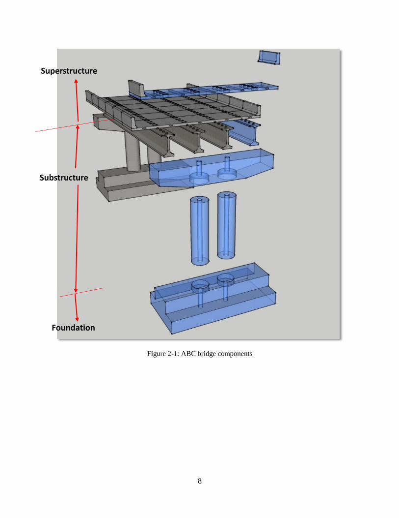
2.1 ABC Bridge Components ABC bridge components, in general, includes superstructure, substructure, and foundation
subsystems (Figure 2-1). The superstructure refers to deck and girders and everything above the
deck [1]. The substructure refers to elements that hold the superstructure like piers, abutments, and
wing walls, basically, everything below the superstructure bearing and above the foundation.
Foundation is a part of substructure that transfers loads from the bridge to the earth and strata. It
can be shallow or deep, and include footings, pile caps, piles, etc. The ABC bridge elements and
components are connected to each other using joints and connections which normally are
established in-situ [2, 3] (Figure 2-2). It should be noted that an alternative definition exists
referring to everything below deck bearing as substructure including the foundation. However,
this report subscribes to a definition of substructure that includes bridge components below the
deck bearing and above the foundation. This definition helps to distinguish better the role of
substructure and foundation as well as a better explanation for the scope of work by parties
performing the project.
2.1.1 Superstructure
The superstructure refers to all the parts that are above the bridge bearing and provide the
horizontal span. These elements carry loads from the deck span and provide the riding surface [4].
Superstructure includes girder and deck slab, miscellaneous elements, barriers, and railing. In
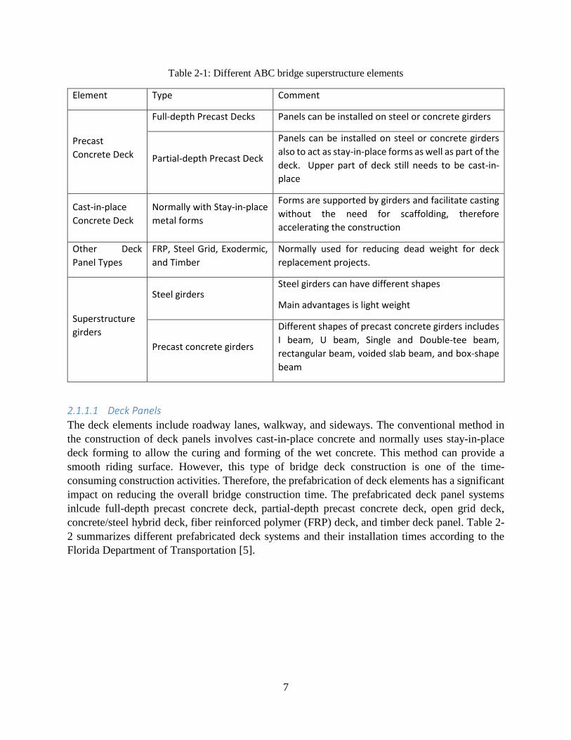
summary, the ABC bridges superstructure components are listed in Table 2-1.
7
Table 2-1: Different ABC bridge superstructure elements
Element Type Comment
Precast
Concrete Deck
Full-depth Precast Decks Panels can be installed on steel or concrete girders
Partial-depth Precast Deck
Panels can be installed on steel or concrete girders
also to act as stay-in-place forms as well as part of the
deck. Upper part of deck still needs to be cast-in-
place
Cast-in-place
Concrete Deck
Normally with Stay-in-place
metal forms
Forms are supported by girders and facilitate casting
without the need for scaffolding, therefore
accelerating the construction
Other Deck
Panel Types
FRP, Steel Grid, Exodermic,
and Timber
Normally used for reducing dead weight for deck
replacement projects.
Superstructure
girders
Steel girders Steel girders can have different shapes
Main advantages is light weight
Precast concrete girders
Different shapes of precast concrete girders includes
I beam, U beam, Single and Double-tee beam,
rectangular beam, voided slab beam, and box-shape
beam
2.1.1.1 Deck Panels
The deck elements include roadway lanes, walkway, and sideways. The conventional method in
the construction of deck panels involves cast-in-place concrete and normally uses stay-in-place
deck forming to allow the curing and forming of the wet concrete. This method can provide a
smooth riding surface. However, this type of bridge deck construction is one of the time-
consuming construction activities. Therefore, the prefabrication of deck elements has a significant
impact on reducing the overall bridge construction time. The prefabricated deck panel systems
inlcude full-depth precast concrete deck, partial-depth precast concrete deck, open grid deck,
concrete/steel hybrid deck, fiber reinforced polymer (FRP) deck, and timber deck panel. Table 2-
2 summarizes different prefabricated deck systems and their installation times according to the
Florida Department of Transportation [5].
8
Figure 2-1: ABC bridge components
Superstructure
Substructure
Foundation
9
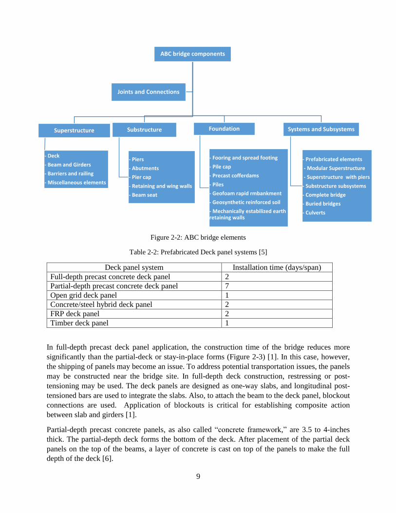
Figure 2-2: ABC bridge elements
Table 2-2: Prefabricated Deck panel systems [5]
Deck panel system Installation time (days/span)
Full-depth precast concrete deck panel 2
Partial-depth precast concrete deck panel 7
Open grid deck panel 1
Concrete/steel hybrid deck panel 2
FRP deck panel 2
Timber deck panel 1
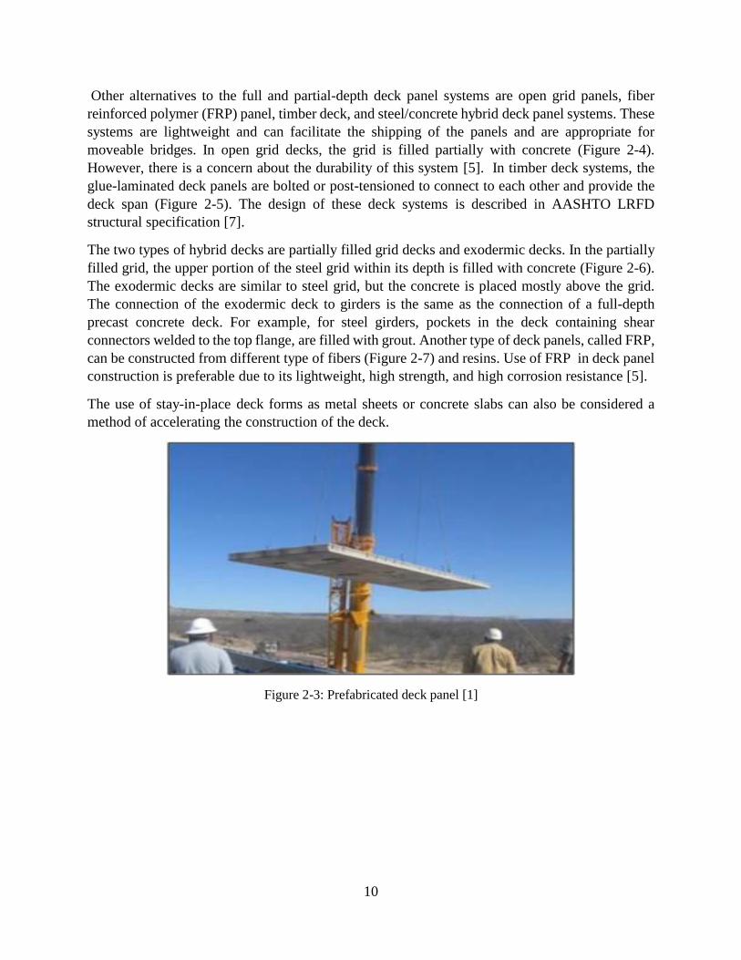
In full-depth precast deck panel application, the construction time of the bridge reduces more
significantly than the partial-deck or stay-in-place forms (Figure 2-3) [1]. In this case, however,
the shipping of panels may become an issue. To address potential transportation issues, the panels
may be constructed near the bridge site. In full-depth deck construction, restressing or post-
tensioning may be used. The deck panels are designed as one-way slabs, and longitudinal post-
tensioned bars are used to integrate the slabs. Also, to attach the beam to the deck panel, blockout
connections are used. Application of blockouts is critical for establishing composite action
between slab and girders [1].
Partial-depth precast concrete panels, as also called “concrete framework,” are 3.5 to 4-inches
thick. The partial-depth deck forms the bottom of the deck. After placement of the partial deck
panels on the top of the beams, a layer of concrete is cast on top of the panels to make the full
depth of the deck [6].
ABC bridge components
Superstructure
- Deck
- Beam and Girders
- Barriers and railing
- Miscellaneous elements
Substructure
- Piers
- Abutments
- Pier cap
- Retaining and wing walls
- Beam seat
Foundation
- Fooring and spread footing
- Pile cap
- Precast cofferdams
- Piles
- Geofoam rapid rmbankment
- Geosynthetic reinforced soil
- Mechanically estabilized earth retaining walls
Systems and Subsystems
- Prefabricated elements
- Modular Superstructure
- Superstructure with piers
- Substructure subsystems
- Complete bridge
- Buried bridges
- Culverts
Joints and Connections
10
Other alternatives to the full and partial-depth deck panel systems are open grid panels, fiber
reinforced polymer (FRP) panel, timber deck, and steel/concrete hybrid deck panel systems. These
systems are lightweight and can facilitate the shipping of the panels and are appropriate for
moveable bridges. In open grid decks, the grid is filled partially with concrete (Figure 2-4).
However, there is a concern about the durability of this system [5]. In timber deck systems, the
glue-laminated deck panels are bolted or post-tensioned to connect to each other and provide the
deck span (Figure 2-5). The design of these deck systems is described in AASHTO LRFD
structural specification [7].
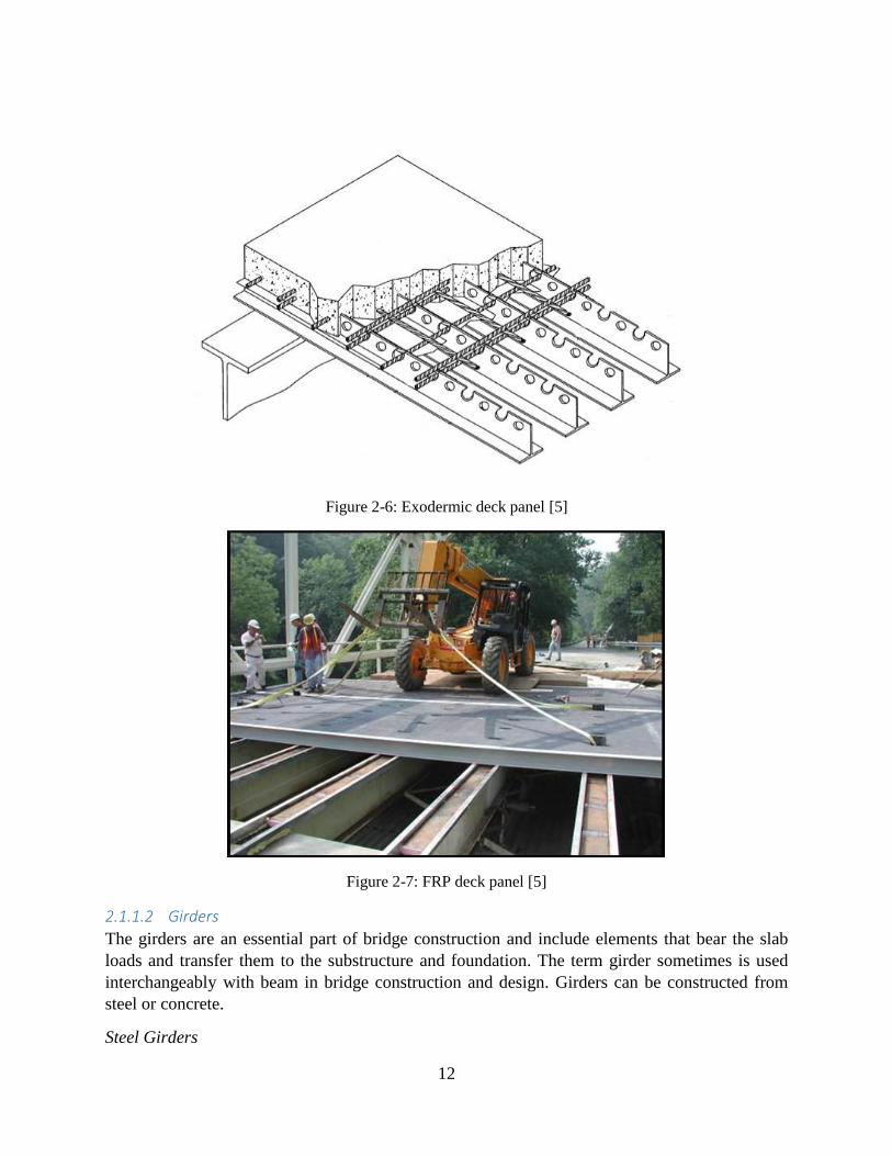
The two types of hybrid decks are partially filled grid decks and exodermic decks. In the partially
filled grid, the upper portion of the steel grid within its depth is filled with concrete (Figure 2-6).
The exodermic decks are similar to steel grid, but the concrete is placed mostly above the grid.
The connection of the exodermic deck to girders is the same as the connection of a full-depth
precast concrete deck. For example, for steel girders, pockets in the deck containing shear
connectors welded to the top flange, are filled with grout. Another type of deck panels, called FRP,
can be constructed from different type of fibers (Figure 2-7) and resins. Use of FRP in deck panel
construction is preferable due to its lightweight, high strength, and high corrosion resistance [5].
The use of stay-in-place deck forms as metal sheets or concrete slabs can also be considered a
method of accelerating the construction of the deck.
Figure 2-3: Prefabricated deck panel [1]

11
Figure 2-4: Open grid deck panel [1]
Figure 2-5: Timber deck panels [5]
12
Figure 2-6: Exodermic deck panel [5]
Figure 2-7: FRP deck panel [5]
2.1.1.2 Girders
The girders are an essential part of bridge construction and include elements that bear the slab
loads and transfer them to the substructure and foundation. The term girder sometimes is used
interchangeably with beam in bridge construction and design. Girders can be constructed from
steel or concrete.
Steel Girders

13
Steel girders can be configured in different shapes (Figure 2-8). The main advantage of using steel
girders is their lightweight that can make shipping of prefabricated steel girders easier. However,
the long-term maintenance and corrosion of steel girders are an issue. This issue, however, can be
addressed by introducing weathering steel girders that require no painting and therefore less
maintenance [1]. Also, it is possible to use steel beam with pre-topped concrete slab for
replacement and construction of superstructure, which is called modular superstructure.
Precast Concrete Beam
Another type of girders is precast prestressed concrete beam. The AASHTO and
precast/prestressed concrete institute (PCI) developed the standardized prefabricated girder shapes
[8]. Different types of precasst concrete girders include I beam, U beam, Single and Double-tee
beam, rectangular beam, voided slab beam, and box shape beam (Figure 2-9). Bulb-tee girders and
decked-girders are two of the most efficient types of girders for ABC construction because they
can eliminate the need for deck placement and decrease the bridge construction time.
Figure 2-8: Steel girder [9]

14
Voided slab beam
Box shape beam
I beam
Bulb-tee beam
Double-tee beam
Figure 2-9: Different shape of precast girders [8]
2.1.1.3 Barriers and railing
The barriers for ABC bridges can be designed and constructed with prefabricated deck, cast in
place, or attached to the deck using fasteners such as bolts (Figure 2-10). The FHWA provided a
manual that defines the barrier and railing requirements for bridges [10]. This manual requires
crash testing for barriers. To this date, no crash tested prefabricated barriers are available [1]. A
prefabricated railing system has been developed recently by Iowa State University researchers as
part of ABC-UTC projects that are verified with static/push-over testing. Next phase of this
research project, aims at verification through crash testing of the proposed prefabricated railing
system (Figure 2-11) [11].

15
Figure 2-10: Deck panel with a barrier [1] Figure 2-11: Deck panel with barrier [11]
2.1.1.4 Miscellaneous elements
Miscellaneous elements of the superstructure include the drainage assembly, lighting, expansion
joints, bridge bearing, and deck overlay or riding surface of the bridge. The deck overlay or
wearing surface can be surface of the bridge without any overlay or can be overlaid with
asphaltmixes. The drainage assembly can be preinstalled on the prefabricated deck elements or
established the same way as conventional bridges [12].
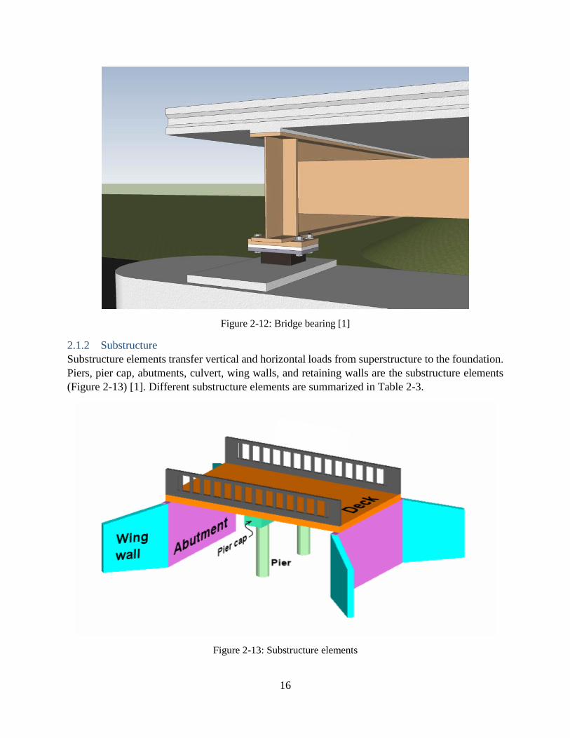
In conventional cast-in-place bridge deck construction, elevation adjustments to deck is performed
by the use of deck hunches between top of the girder and bottom of the deck. In ABC projects
with prefabricated girders and deck, bridge bearing is placed between girder and cap beam to
provide bearing and adjust the elevation of girder and deck to provide proper, durable and uniform
seating for the girders (Figure 2-12) [1].
The deck expansion joints are necessary for accommodating changes due to temperature variation
and preventing premature deterioration or overloading of the bridge [13]. Expansion joints are not
used for the case of integral abutments that become monolithic with the superstructure [1].
Expansion joints can be categorized into two groups [1]. The first group includes joints within the
deck overlay and consists of asphaltic plug material and epoxy header with glands or seals. The
second group includes joints embedded into the deck. The embedded joints experience large
movements. Different types of embedded joints include modular expansion joints, armored seals,
or finger joints. The issue with expansion joints is that they can deteriorate rapidly and need high
maintenance. To address this issue, link slab has been introduced to eliminate the use of expansion
joints in ABC projects [14]. Practical recommendation and guideline to use link slab in the ABC
projects is under development and will be available shortly.
16
Figure 2-12: Bridge bearing [1]
2.1.2 Substructure
Substructure elements transfer vertical and horizontal loads from superstructure to the foundation.
Piers, pier cap, abutments, culvert, wing walls, and retaining walls are the substructure elements
(Figure 2-13) [1]. Different substructure elements are summarized in Table 2-3.
Figure 2-13: Substructure elements
17
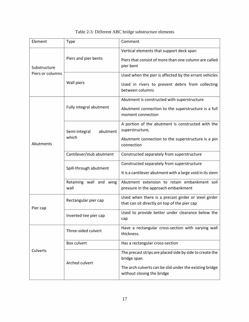
Table 2-3: Different ABC bridge substructure elements
Element Type Comment
Substructure
Piers or columns
Piers and pier bents
Vertical elements that support deck span
Piers that consist of more than one column are called
pier bent
Wall piers
Used when the pier is affected by the errant vehicles
Used in rivers to prevent debris from collecting
between columns
Abutments
Fully integral abutment
Abutment is constructed with superstructure
Abutment connection to the superstructure is a full
moment connection
Semi-integral abutment
which
A portion of the abutment is constructed with the
superstructure,
Abutment connection to the superstructure is a pin
connection
Cantilever/stub abutment Constructed separately from superstructure
Spill-through abutment Constructed separately from superstructure
It is a cantilever abutment with a large void in its stem
Retaining wall and wing
wall
Abutment extension to retain embankment soil
pressure in the approach embankment
Pier cap
Rectangular pier cap Used when there is a precast girder or steel girder
that can sit directly on top of the pier cap
Inverted-tee pier cap Used to provide better under clearance below the
cap
Culverts
Three-sided culvert Have a rectangular cross-section with varying wall
thickness.
Box culvert Has a rectangular cross-section
Arched culvert
The precast strips are placed side by side to create the
bridge span
The arch culverts can be slid under the existing bridge
without closing the bridge
18
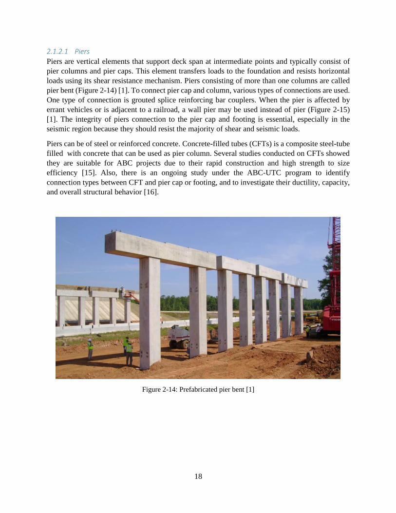
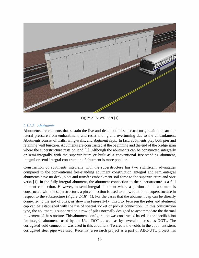
2.1.2.1 Piers
Piers are vertical elements that support deck span at intermediate points and typically consist of
pier columns and pier caps. This element transfers loads to the foundation and resists horizontal
loads using its shear resistance mechanism. Piers consisting of more than one columns are called
pier bent (Figure 2-14) [1]. To connect pier cap and column, various types of connections are used.
One type of connection is grouted splice reinforcing bar couplers. When the pier is affected by
errant vehicles or is adjacent to a railroad, a wall pier may be used instead of pier (Figure 2-15)
[1]. The integrity of piers connection to the pier cap and footing is essential, especially in the
seismic region because they should resist the majority of shear and seismic loads.
Piers can be of steel or reinforced concrete. Concrete-filled tubes (CFTs) is a composite steel-tube
filled with concrete that can be used as pier column. Several studies conducted on CFTs showed
they are suitable for ABC projects due to their rapid construction and high strength to size
efficiency [15]. Also, there is an ongoing study under the ABC-UTC program to identify
connection types between CFT and pier cap or footing, and to investigate their ductility, capacity,
and overall structural behavior [16].
Figure 2-14: Prefabricated pier bent [1]
19
Figure 2-15: Wall Pier [1]
2.1.2.2 Abutments
Abutments are elements that sustain the live and dead load of superstructure, retain the earth or
lateral pressure from embankment, and resist sliding and overturning due to the embankment.
Abutments consist of walls, wing-walls, and abutment caps. In fact, abutments play both pier and
retaining wall function. Abutments are constructed at the beginning and the end of the bridge span
where the superstructure rests on land [1]. Although the abutments can be constructed integrally
or semi-integrally with the superstructure or built as a conventional free-standing abutment,
integral or semi-integral construction of abutment is more popular.
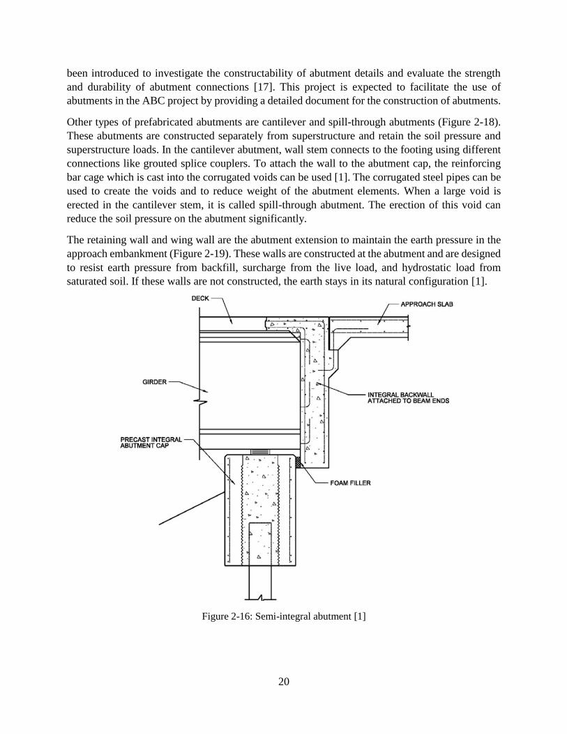
Construction of abutments integrally with the superstructure has two significant advantages
compared to the conventional free-standing abutment construction. Integral and semi-integral
abutments have no deck joints and transfer embankment soil force to the superstructure and vice
versa [1]. In the fully integral abutment, the abutment connection to the superstructure is a full
moment connection. However, in semi-integral abutment where a portion of the abutment is
constructed with the superstructure, a pin connection is used to allow rotation of superstructure in
respect to the substructure (Figure 2-16) [1]. For the cases that the abutment cap can be directly
connected to the end of piles, as shown in Figure 2-17, integrity between the piles and abutment
cap can be established with the use of special socket or pocket connection. In this construction
type, the abutment is supported on a row of piles normally designed to accommodate the thermal
movement of the structure. This abutment configuration was constructed based on the specification
for integral abutments used by the Utah DOT as well as by several other states DOTs. The
corrugated void connection was used in this abutment. To create the voids in the abutment stem,
corrugated steel pipe was used. Recently, a research project as a part of ABC-UTC project has
20
been introduced to investigate the constructability of abutment details and evaluate the strength
and durability of abutment connections [17]. This project is expected to facilitate the use of
abutments in the ABC project by providing a detailed document for the construction of abutments.
Other types of prefabricated abutments are cantilever and spill-through abutments (Figure 2-18).
These abutments are constructed separately from superstructure and retain the soil pressure and
superstructure loads. In the cantilever abutment, wall stem connects to the footing using different
connections like grouted splice couplers. To attach the wall to the abutment cap, the reinforcing
bar cage which is cast into the corrugated voids can be used [1]. The corrugated steel pipes can be
used to create the voids and to reduce weight of the abutment elements. When a large void is
erected in the cantilever stem, it is called spill-through abutment. The erection of this void can
reduce the soil pressure on the abutment significantly.
The retaining wall and wing wall are the abutment extension to maintain the earth pressure in the
approach embankment (Figure 2-19). These walls are constructed at the abutment and are designed
to resist earth pressure from backfill, surcharge from the live load, and hydrostatic load from
saturated soil. If these walls are not constructed, the earth stays in its natural configuration [1].
Figure 2-16: Semi-integral abutment [1]

21
Figure 2-17: Prefabricated integral abutment [1]
Figure 2-18: Prefabricated cantilever abutment [1]
22
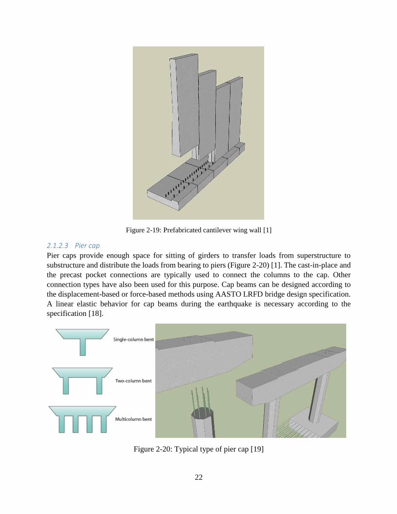
Figure 2-19: Prefabricated cantilever wing wall [1]
2.1.2.3 Pier cap
Pier caps provide enough space for sitting of girders to transfer loads from superstructure to
substructure and distribute the loads from bearing to piers (Figure 2-20) [1]. The cast-in-place and
the precast pocket connections are typically used to connect the columns to the cap. Other
connection types have also been used for this purpose. Cap beams can be designed according to
the displacement-based or force-based methods using AASTO LRFD bridge design specification.
A linear elastic behavior for cap beams during the earthquake is necessary according to the
specification [18].
Figure 2-20: Typical type of pier cap [19]
23
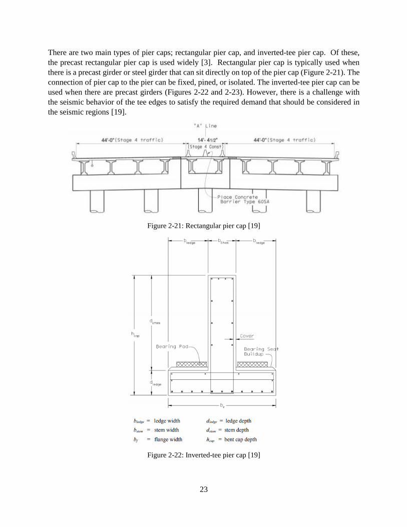
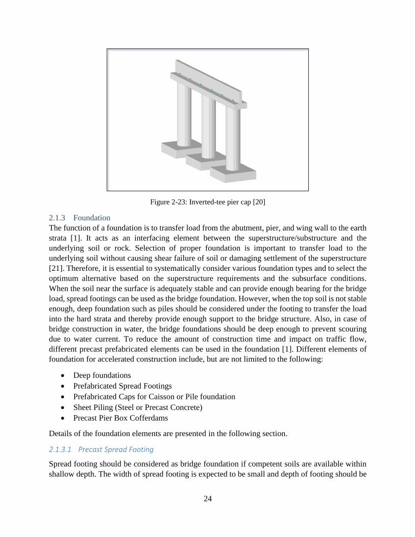
There are two main types of pier caps; rectangular pier cap, and inverted-tee pier cap. Of these,
the precast rectangular pier cap is used widely [3]. Rectangular pier cap is typically used when
there is a precast girder or steel girder that can sit directly on top of the pier cap (Figure 2-21). The
connection of pier cap to the pier can be fixed, pined, or isolated. The inverted-tee pier cap can be
used when there are precast girders (Figures 2-22 and 2-23). However, there is a challenge with
the seismic behavior of the tee edges to satisfy the required demand that should be considered in
the seismic regions [19].
Figure 2-21: Rectangular pier cap [19]
Figure 2-22: Inverted-tee pier cap [19]
24
Figure 2-23: Inverted-tee pier cap [20]
2.1.3 Foundation
The function of a foundation is to transfer load from the abutment, pier, and wing wall to the earth
strata [1]. It acts as an interfacing element between the superstructure/substructure and the
underlying soil or rock. Selection of proper foundation is important to transfer load to the
underlying soil without causing shear failure of soil or damaging settlement of the superstructure
[21]. Therefore, it is essential to systematically consider various foundation types and to select the
optimum alternative based on the superstructure requirements and the subsurface conditions.
When the soil near the surface is adequately stable and can provide enough bearing for the bridge
load, spread footings can be used as the bridge foundation. However, when the top soil is not stable
enough, deep foundation such as piles should be considered under the footing to transfer the load
into the hard strata and thereby provide enough support to the bridge structure. Also, in case of
bridge construction in water, the bridge foundations should be deep enough to prevent scouring
due to water current. To reduce the amount of construction time and impact on traffic flow,
different precast prefabricated elements can be used in the foundation [1]. Different elements of
foundation for accelerated construction include, but are not limited to the following:
Deep foundations
Prefabricated Spread Footings
Prefabricated Caps for Caisson or Pile foundation
Sheet Piling (Steel or Precast Concrete)
Precast Pier Box Cofferdams
Details of the foundation elements are presented in the following section.
2.1.3.1 Precast Spread Footing
Spread footing should be considered as bridge foundation if competent soils are available within
shallow depth. The width of spread footing is expected to be small and depth of footing should be

25
economically feasible [21]. Shallow spread footings require significantly less time to excavate and
place than deep foundations such as drilled or driven piles. If necessary, ground improvement
methods can be used to improve the subsurface conditions for shallow spread footing [21].
Generally, spread footings are constructed using cast-in-place methods. However, precast spread
footings are also available for bridge foundation. These footings are precast off-site, transported
to the construction site and placed on a prepared subgrade and then grouted in place [22]. However,
transporting precast concrete footings may be challenging as the size of footings can get quite large
for bridge loads [1]. A new hybrid system can be applied which allows the installation of the
footing at the speed of precast with the economy of cast-in-place. In such cases, a precast concrete
footing is used only under the columns. A continuous footing is then obtained by using a cast-in-
place closure pour on extended reinforcing bars from precast concrete footing during the erection
of the remaining portions of the bridge [1]. The completed continuous footing is designed to
support all other loads. Figure 2.24 presents a schematic of precast spread footing as bridge
foundation.
Figure 2-24 Precast spread footing as bridge foundation [1]
2.1.3.2 Deep Foundations
Deep foundations are selected when competent soils or rocks cannot be found on the top stratum
or if there is a possibility of extensive scour, liquefaction or lateral spread [23]. Deep foundations
are one of the most commonly used foundations for bridges by many state agencies [23-25].
Different types of deep foundations such as driven piles, micropiles, continuous flight auger (CFA)
piles, or drilled shafts are frequently used as bridge foundation [26, 1, 23-25, 21]. Generally, a cap
is built with the pile foundation to provide a stable platform for supporting substructure. Also, piles
can be directly connected to the bent cap for short span bridges. Pile bents are cost effective and
can be built quickly since there is no need for a footing. Most pile bents are constructed with
precast concrete piles [1].
26
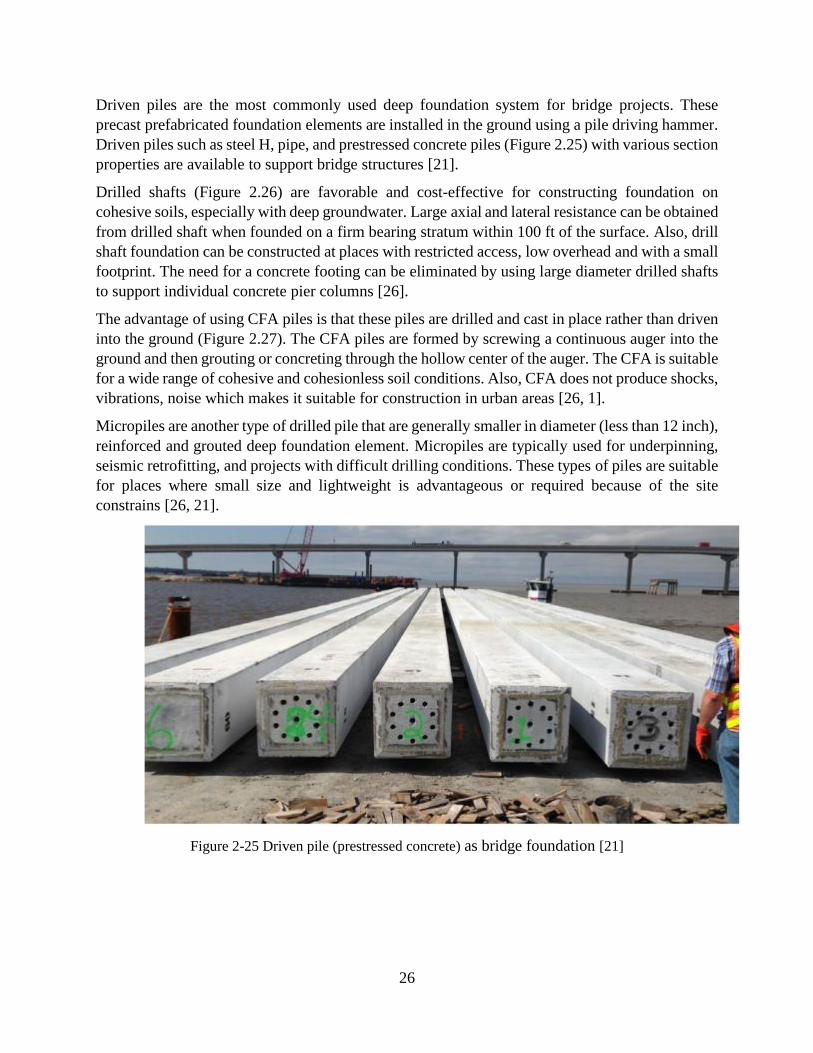
Driven piles are the most commonly used deep foundation system for bridge projects. These
precast prefabricated foundation elements are installed in the ground using a pile driving hammer.
Driven piles such as steel H, pipe, and prestressed concrete piles (Figure 2.25) with various section
properties are available to support bridge structures [21].
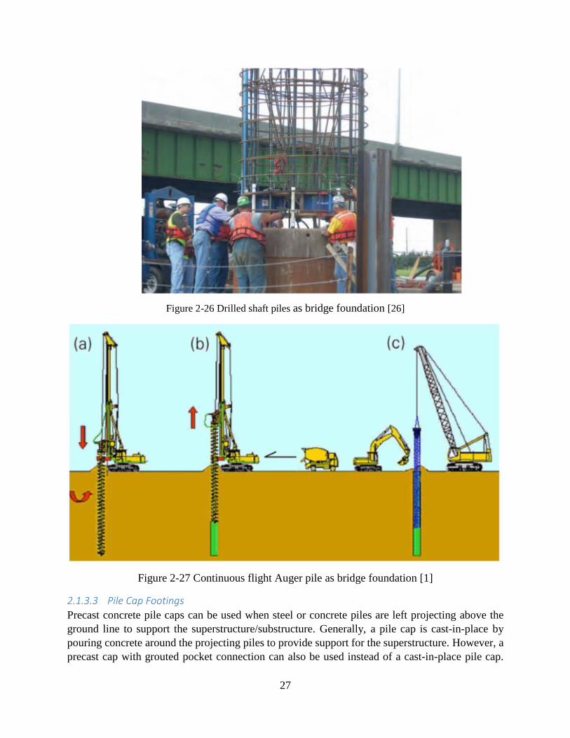
Drilled shafts (Figure 2.26) are favorable and cost-effective for constructing foundation on
cohesive soils, especially with deep groundwater. Large axial and lateral resistance can be obtained
from drilled shaft when founded on a firm bearing stratum within 100 ft of the surface. Also, drill
shaft foundation can be constructed at places with restricted access, low overhead and with a small
footprint. The need for a concrete footing can be eliminated by using large diameter drilled shafts
to support individual concrete pier columns [26].
The advantage of using CFA piles is that these piles are drilled and cast in place rather than driven
into the ground (Figure 2.27). The CFA piles are formed by screwing a continuous auger into the
ground and then grouting or concreting through the hollow center of the auger. The CFA is suitable
for a wide range of cohesive and cohesionless soil conditions. Also, CFA does not produce shocks,
vibrations, noise which makes it suitable for construction in urban areas [26, 1].
Micropiles are another type of drilled pile that are generally smaller in diameter (less than 12 inch),
reinforced and grouted deep foundation element. Micropiles are typically used for underpinning,
seismic retrofitting, and projects with difficult drilling conditions. These types of piles are suitable
for places where small size and lightweight is advantageous or required because of the site
constrains [26, 21].
Figure 2-25 Driven pile (prestressed concrete) as bridge foundation [21]
27
Figure 2-26 Drilled shaft piles as bridge foundation [26]
Figure 2-27 Continuous flight Auger pile as bridge foundation [1]
2.1.3.3 Pile Cap Footings
Precast concrete pile caps can be used when steel or concrete piles are left projecting above the
ground line to support the superstructure/substructure. Generally, a pile cap is cast-in-place by
pouring concrete around the projecting piles to provide support for the superstructure. However, a
precast cap with grouted pocket connection can also be used instead of a cast-in-place pile cap.

28
The connection between the cap and the piles is achieved by filling the grout pockets with an epoxy
grout [1, 22]. A number of different pile cap connections are detailed in the FHWA Connections
Manual [2] to ensure punching shear and moment resistance at the connections. Figure 2.28
presents a sketch of precast concrete pile cap placed on precast concrete piles.
Figure 2-28: Prefabricated pile cap footing [1]
2.1.3.4 Precast Pier Box Cofferdams
In case of bridge construction in water, a precast concrete pier box is used to dewater the area
where deep foundation connects to substructure. This structure can sit over the shaft and be sealed
to provide a dry condition during construction of footing. Also, the precast pier box systems can
eliminate the need for complicated cofferdams and dewatering systems. This prefabricating system
can be floated downstream from the place of cast and set into place to block off water flow for the
installation of the pile caps. Also, these can be used as an additional corrosion protection system
for the new pier footing when built with high performance concrete. Additionally, significant
savings in time and money in the construction of the foundations can be achieved by using the
precast concrete pier boxes [1, 22]. Figure 2.29 presents a precast concrete pier box that allows
construction of footings in a dry environment.

29
Figure 2-29: Precast concrete pier box cofferdam [1]
2.1.3.5 Precast Sheet Piling
Precast concrete sheet pile and cellular steel sheet piles are most commonly used sheet piling
systems for foundation construction and excavation support. Standards for precast concrete sheet
piling was developed by Florida DOT. Typically, two types of cellular sheet piles are available,
namely closed cell sheeting and open cell sheeting [1]. These precast prefabricated elements can
be used to accelerate construction of bridge piers and abutments.
A geotechnical engineering scan tour of Europe was organized by FHWA and AAASHTO in June
2002 to evaluate the use of different accelerated bridge construction technologies. Based on the
findings from that scan tour, Dumas et al. [27] presented a comparison (Table 2.4) between bridge
foundation systems, equipment, and ground improvement methods for poor subgrade. According
to Dumas et al. [27], the standard of practice for bridge foundation construction in the U.S. is
driven piles or drilled shafts as CFA piles were found to have problem with quality control/quality
assurance. An alternative for rapid construction could be the use of CFA piles with automated
computer control and automated QC/QA. Another alternate accelerated method suggested by the
scan team was bored cased secant (CSP) piles which can be used for both bridge support and
excavation support involving cut situations. Accelerated bridge construction technologies such as
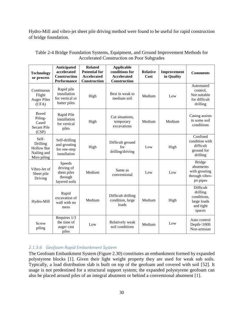
30
Hydro-Mill and vibro-jet sheet pile driving method were found to be useful for rapid construction
of bridge foundation.
Table 2-4 Bridge Foundation Systems, Equipment, and Ground Improvement Methods for
Accelerated Construction on Poor Subgrades
Technology
or process
Anticipated
accelerated
Construction
Performance
Related
Potential for
Accelerated
Construction
Applicable
conditions for
Accelerated
Construction
Relative
Cost
Improvement
in Quality Comments
Continuous
Flight
Auger Piles
(CFA)
Rapid pile
installation
for vertical or
batter piles
High Best in weak to
medium soil Medium Low
Automated
control,
Not suitable
for difficult
drilling
Bored
Piling-
Cased
Secant Pile
(CSP)
Rapid Pile
installation
for vertical
piles
High
Cut situations,
temporary
excavations
Medium Medium
Casing assists
in some soil
conditions
Self-
Drilling
Hollow Bar
Nailing and
Miro piling
Self-drilling
and grouting
for one-step
installation
High
Difficult ground
for
drilling/driving
Low High
Confined
condition with
difficult
ground for
drilling
Vibro-Jet of
Sheet pile
Driving
Speeds
driving of
sheet piles
through
layered soils
Medium Same as
conventional Low Low
Bridge
abutments
with grouting
through vibro-
jet pipes
Hydro-Mill
Rapid
excavation of
wall with no
mess
Medium
Difficult drilling
condition, large
loads
Medium High
Difficult
drilling
conditions,
large loads
and tight
spaces
Screw
piling
Requires 1/3
the time of
auger cast
piles
Low Relatively weak
soil conditions Medium Low
Auto control
Depth<100ft
Non-artesian
2.1.3.6 Geofoam Rapid Embankment System
The Geofoam Embankment System (Figure 2.30) constitutes an embankment formed by expanded
polystyrene blocks [1]. Given their light weight property they are used for weak sub soils.
Typically, a load distribution slab is built on top of the geofoam and covered with soil [52]. It
usage is not predestined for a structural support system; the expanded polystyrene geofoam can
also be placed around piles of an integral abutment or behind a conventional abutment [1].

31
Application of this technology is mainly for but not limited to reducing swell pressure of swell-
type soils, reduce lateral earth pressure and reduction of settlement in embankments [52].
Moreover, benefits of this system include the elimination of pre-load settlement times, extremely
lightweight material and fast construction [1].
The design considerations for this system is straightforward. Site is leveled, and layer of bedding
sand needs to be placed. Geofoam are then placed with bedding sand that will fill the gap between
backslope and geofoam. A load distribution slab is placed on top of the geofoam and then a layer
of fill over the slab, and finally covered by the pavement [53].
Figure 2-30: EPS Geofoam Embankment (Source ACH Foam Technologies)
2.1.3.7 Geosynthetic Reinforced Soil (GRS) Integrated Bridge System
GRS refers to an innovative geotechnical system that combines properties of granular soil and
geosynthetic material to improve strength and stiffness of a soil mass. GRS systems are somewhat
analogous to reinforced concrete. Both plain concrete and soil perform adequately in compression
and shear, but lack strength and ductility in tension. The addition of rebar in concrete and
geosynthetics in soil improves performance of both materials. GRS systems were shown to have a
beneficial application to short-span bridges in recent years [28]. The GRS needs to be finished
with a beam seat or cap to receive the superstructure. Figure 2.31 shows an example of GRS/IBS
Bridge abutment.
A recent form of abutment system is the Geosynthetic Reinforced Soil Integrated Bridge System
(GRSIBS), which is described in FHWA publication FHWA-HRT-11-027 (Adams et al. 2011).
This is a relatively new abutment system that has been used for accelerated bridge construction,
and typically for short spans up to about 140 feet. The abutment uses alternating thin layers of
compacted fill and geosynthetic reinforcement sheets that combine to form a reinforced soil mass
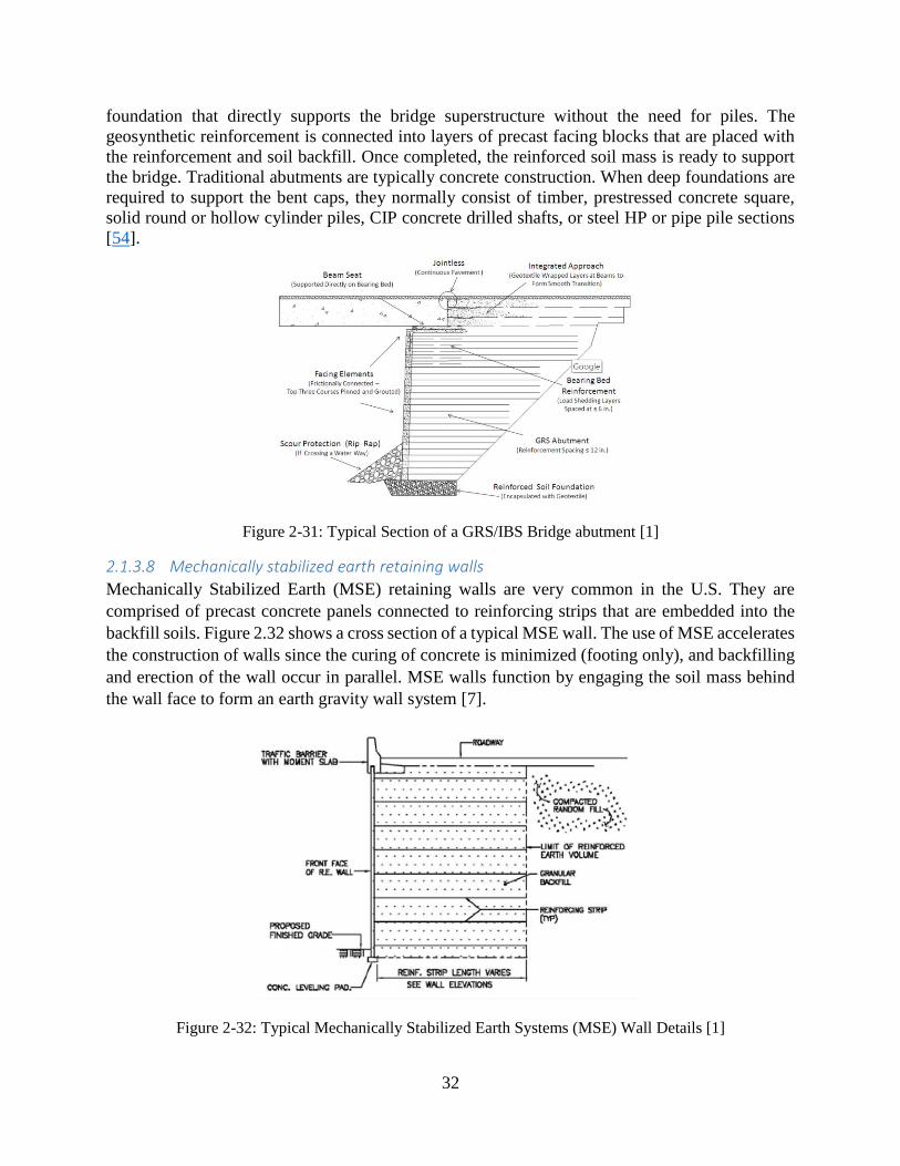
32
foundation that directly supports the bridge superstructure without the need for piles. The
geosynthetic reinforcement is connected into layers of precast facing blocks that are placed with
the reinforcement and soil backfill. Once completed, the reinforced soil mass is ready to support
the bridge. Traditional abutments are typically concrete construction. When deep foundations are
required to support the bent caps, they normally consist of timber, prestressed concrete square,
solid round or hollow cylinder piles, CIP concrete drilled shafts, or steel HP or pipe pile sections
[54].
Figure 2-31: Typical Section of a GRS/IBS Bridge abutment [1]
2.1.3.8 Mechanically stabilized earth retaining walls
Mechanically Stabilized Earth (MSE) retaining walls are very common in the U.S. They are
comprised of precast concrete panels connected to reinforcing strips that are embedded into the
backfill soils. Figure 2.32 shows a cross section of a typical MSE wall. The use of MSE accelerates
the construction of walls since the curing of concrete is minimized (footing only), and backfilling
and erection of the wall occur in parallel. MSE walls function by engaging the soil mass behind
the wall face to form an earth gravity wall system [7].
Figure 2-32: Typical Mechanically Stabilized Earth Systems (MSE) Wall Details [1]

33
There are also wall systems that use GRS fabric, wire mesh or natural vegetation in place of the
wall panel facings. The construction of these walls can progress rapidly because the system is built
while the soil is being placed behind the wall; thereby combining two processes into one [1].
Many states also use MSE walls for abutments; however, the walls typically do not support the
bridge. Piles or drilled shafts are installed prior to wall construction. The MSE wall is then typically
built in front of the piles with the reinforcing strips placed between the piles. Once complete, a
concrete footing is installed on top of the piles, creating two separate structures [7].
2.1.4 Systems and Subsystems
In construction of bridge, it is sometime more efficient to assemble prefabricated elements off-site
or combine several elements (e.g., deck with girder) to further reduce the time of construction and
provide a better quality. In some cases, structural elements and miscellaneous elements of a bridge
can be prefabricated together. These systems are summarized in Table 2-5 and described as follow.
In some cases, a larger portion of the superstructure is constructed normally near the site and
moved in place onto the substructure. Sometime, the entire length and width of the bridge
superstructure, with or without miscellaneous elements, is prefabricated and installed onto the
substructure using one of the installation methods such as lifting, SPMT, and sliding horizontally
or transversely. In some instances, entire superstructure is fabricated with part or all the
substructure and moved or placed on the footing. Prefabricated superstructure elements and
systems are summarized in Table 2-5.
As an alternative to traditional bridges, buried bridges can sometime offer economic solution,
especially for hydraulic and minor road crossings. A buried bridge is a buried structure supporting
a roadway that relies on the support from the soil-structure-interaction. The design and installation
of buried bridges have evolved over the years to accommodate longer spans inclusive of the range
for short-span bridges. Since major segments, sometimes the entire superstructure and
substructure, are prefabricated away from site and installed in place, they certainly qualify as ABC
bridges. Furthermore, it qualifies as ABC Systems or Subsystem in that it often combines
superstructure and substructure. Although culverts that are defined with spans of less than 20 ft
may not count ass bridges, but for completeness, culverts are also reviewed here briefly. They
certainly combine substructure, and for the case of boxes the foundation, with the superstructure
as a system.

34
Table 2-5: Different ABC bridge systems and subsystems
System Type Comment
Modular
superstructure
systems
Modular steel systems
Different modular steel systems include multi-beams
unit, modular steel folded plate girder system, and
orthotropic steel deck system
Precast concrete modular
systems
Different precast concrete modular systems include
double tees and decked bulb tees.
Modular timber system
All the elements are prefabricated. The laminated
girder deck system is installed on the top of timber or
steel beam.
Complete bridge
superstructure
subsystem
Entire width of
superstructure with or
without miscellenous
elements
The superstructure can be entirely fabricated off-site
and moved to be installed on site
Complete bridge
system
Superstructure with
integral piers
The entire width of superstructure can be
constructed along with part or entire substructure
and moved or slid on footing
Substructure
subsystem
Piers with column and
footing
The column piers and column can be constructed
together or along with footing
Buried bridges
In the form of three-sided
or full box, or arhc systems
covering spans larger than
20 ft
Their design accounts for support from surrounding
soil. They are normally used for remote site access,
aquatic crossings, pedestrian tunnels, temporary
detours, and it can support heavy live loading for
trucks, mine vehicles, etc.
Culverts Three-sided or box system
for spans smaller than 20 ft
Normally to accommodate the flow of stormwater
and sewage.
2.1.4.1 Modular Superstructure Subsystems
The modular superstructure system is an integral fabrication of deck panels, girders, and their
connections together. In this system, the panels are connected to each other at the edges using
grouted shear connector pockets (shear keys) [1]. To pour the closures and pockets, a low
shrinkage pour should be used to prevent transverse cracking. The limitation in the dimension of
the modular systems is controlled by their heavy weight and long length that can make their

35
shipping difficult. Therefore, the modular steel system is more desirable than modular precast
concrete systems due to its light weight.
Modular steel systems can be topped multi-beams unit, modular steel folded plate girder system,
or orthotropic steel deck system. Topped multi-beams system includes two or three steel beams
that are topped with reinforced concrete (Figure 2-33) [1]. Another system is the modular steel
folded plate girder that in its current form can be used for short span bridges with a maximum span
of 60 feet (Figure 2-34) because of camber limitation. This system has a tube section built by
bending of a flat plate. The advantage of this system is its stability. It does not require any external
or local frames [29]. A new folded plate girder is under investigation by Accelerated Bridge
Construction - University Transportation Center (ABC-UTC) that promises spans as long as 100
ft. or longer [30]. Orthotropic steel deck system is another modular steel system that can be
fabricated in the form of single span orthotropic with the running of ribs on the deck span or
orthotropic T beam. In orthotropic T beam system, steel girders and a portion of the orthotropic
deck are used together as shown in Figure 2-35. The disadvantage of the orthotropic system is its
high cost. The FHWA is developing a standardized method and technique for the construction of
modular orthotropic systems to reduce cost [1].
Modular precast concrete superstructure systems include double tees and decked bulb tees. A
double tee modular system includes two girders connected with a deck slab as shown in Figure 2-
36. In the double tee modular superstructure, the adjacent beams normally connect to each other
using the shear key connection. Bulb tee system consists of a girder with an extended top flange.
In the bulb tees systems, the connection of two adjacent bulb tees is normally established using
the welded tab connection. This type of connection limits the use of this system to low volume
roads due to the low durability of the connection [1].
Another modular superstructure system is the modular timber elements system (Figure 2-37). In
this system, all the elements are prefabricated, and the laminated girder deck system is then
installed on the top of timber or steel beam.
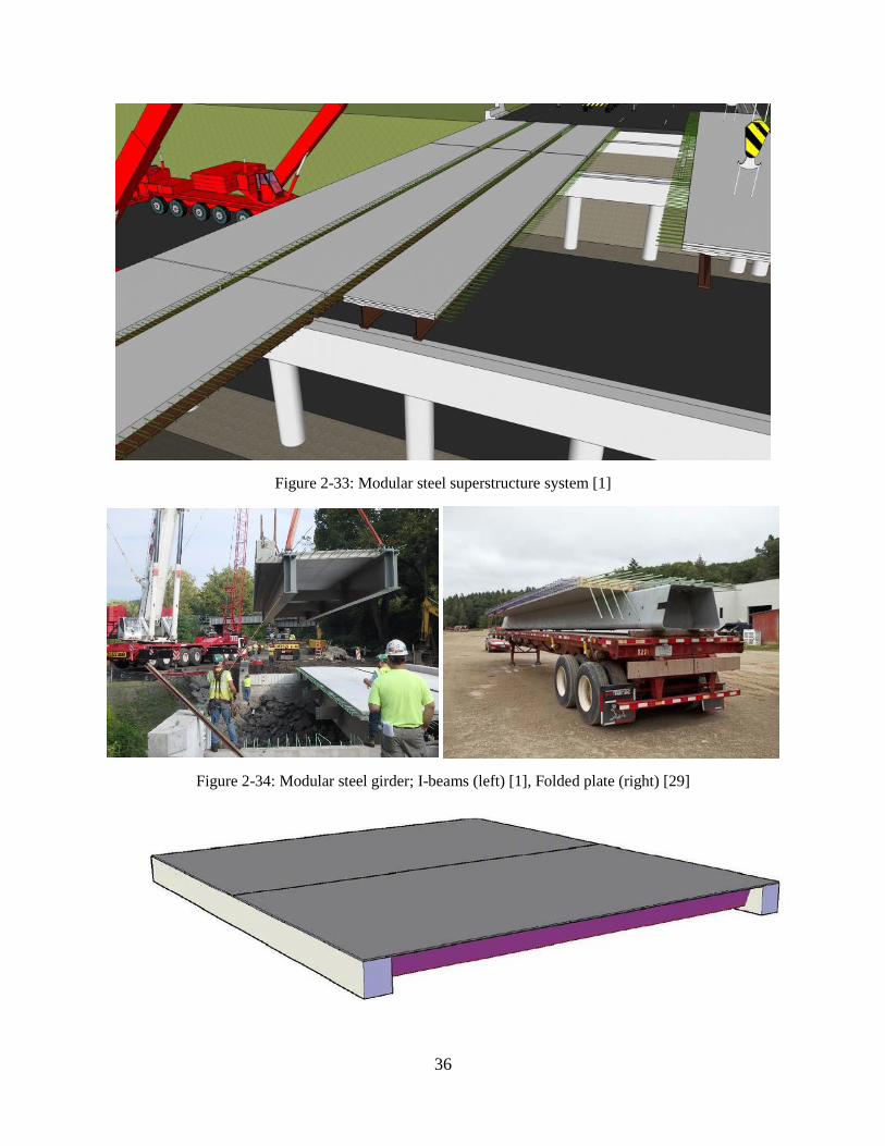
36
Figure 2-33: Modular steel superstructure system [1]
Figure 2-34: Modular steel girder; I-beams (left) [1], Folded plate (right) [29]
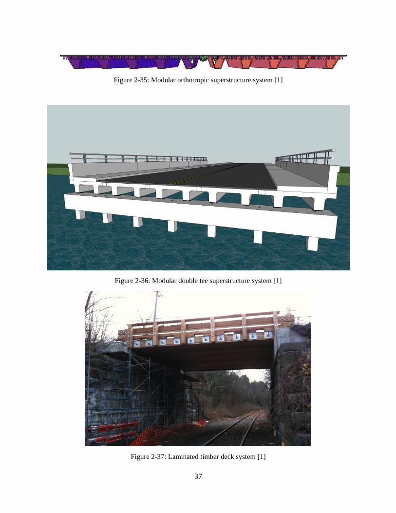
37
Figure 2-35: Modular orthotropic superstructure system [1]
Figure 2-36: Modular double tee superstructure system [1]
Figure 2-37: Laminated timber deck system [1]
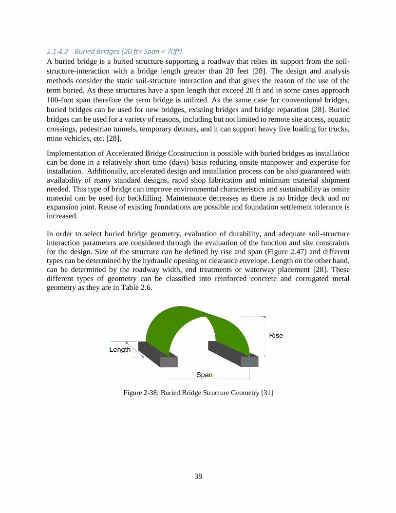
38
2.1.4.2 Buried Bridges (20 ft< Span < 70ft)
A buried bridge is a buried structure supporting a roadway that relies its support from the soil-
structure-interaction with a bridge length greater than 20 feet [28]. The design and analysis
methods consider the static soil-structure interaction and that gives the reason of the use of the
term buried. As these structures have a span length that exceed 20 ft and in some cases approach
100-foot span therefore the term bridge is utilized. As the same case for conventional bridges,
buried bridges can be used for new bridges, existing bridges and bridge reparation [28]. Buried
bridges can be used for a variety of reasons, including but not limited to remote site access, aquatic
crossings, pedestrian tunnels, temporary detours, and it can support heavy live loading for trucks,
mine vehicles, etc. [28].
Implementation of Accelerated Bridge Construction is possible with buried bridges as installation
can be done in a relatively short time (days) basis reducing onsite manpower and expertise for
installation. Additionally, accelerated design and installation process can be also guaranteed with
availability of many standard designs, rapid shop fabrication and minimum material shipment
needed. This type of bridge can improve environmental characteristics and sustainability as onsite
material can be used for backfilling. Maintenance decreases as there is no bridge deck and no
expansion joint. Reuse of existing foundations are possible and foundation settlement tolerance is
increased.
In order to select buried bridge geometry, evaluation of durability, and adequate soil-structure
interaction parameters are considered through the evaluation of the function and site constraints
for the design. Size of the structure can be defined by rise and span (Figure 2.47) and different
types can be determined by the hydraulic opening or clearance envelope. Length on the other hand,
can be determined by the roadway width, end treatments or waterway placement [28]. These
different types of geometry can be classified into reinforced concrete and corrugated metal
geometry as they are in Table 2.6.
Figure 2-38; Buried Bridge Structure Geometry [31]

39
Table 2-6: Buried Bridge Geometry [31]
2.1.4.2.1 Reinforced Concrete
Use of plant precasting of standardized sections is another way in which accelerated bridge
construction can be implemented. Several manufacturers have developed precast concrete box,
three-sided, and arch systems. These systems can be filled with onsite or granular backfill.
Sometimes, these structures can be slid under existing bridges without interrupting existing
roadway. Voids between both structures can then be filled with or without removal of existing
bridges [1].
2.1.4.2.1.1 Rectangular (Box):
- Span range of 8 ft to 48 ft,
- Common uses: culverts and short span bridges
A variety of sizes, depths and for different live loads are offered in precast concrete box buried
bridges. The speed of construction is one of the major advantages when using a precast concrete
box [32]. An example of a rectangular (box) buried bridge can be seen in Figure 2.39.

40
Figure 2-39: Rectangular (box) buried bridge [31]
2.1.4.2.1.2 Three-Sided:
- Span range of 8 ft to 48 ft,
- Common uses: culverts and short span bridges
Three-sided structure was created by a change in the design of the box culvert by removing the
floor slab, this was done so it could comply with some environmental restrictions. Therefore, this
type of design is used when there is limitation with hydraulic and environmental challenges in
some states [33]. Figure 2.40 is an example of three-sided buried bridges.
Figure 2-40: Three-sided buried bridge [31]

41
2.1.4.2.1.3 Arch:
- Span range of 15 ft to 102 ft,
- common uses: culverts and short span bridges. For low, wide waterway enclosures,
aesthetic bridges
Another environmentally friendly, bottomless option is the arch. Depending on the span length
arches can come in one or two pieces. As is the case in Figure 2.41 where a longer span is needed
the tow piece arch rebar from each element is tied together at midspan [33] (Figure 2-42).
Figure 2-41: Arch System[31]
Figure 2-42: Arch buried bridge[31]
2.1.4.2.2 Corrugated Metal
Several corrugated metal plates are bolted together to form these bridge systems [33]. Corrugated
Metal Buried bridges are defined below:
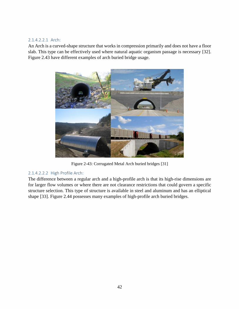
42
2.1.4.2.2.1 Arch:
An Arch is a curved-shape structure that works in compression primarily and does not have a floor
slab. This type can be effectively used where natural aquatic organism passage is necessary [32].
Figure 2.43 have different examples of arch buried bridge usage.
Figure 2-43: Corrugated Metal Arch buried bridges [31]
2.1.4.2.2.2 High Profile Arch:
The difference between a regular arch and a high-profile arch is that its high-rise dimensions are
for larger flow volumes or where there are not clearance restrictions that could govern a specific
structure selection. This type of structure is available in steel and aluminum and has an elliptical
shape [33]. Figure 2.44 possesses many examples of high-profile arch buried bridges.

43
Figure 2-44: High Profile Arch buried bridges [31]
2.1.4.2.2.3 Box Shapes
Figure 2.45 is an example of box shapes. It can be observed that is neither arch shaped nor
rectangular, but uses a flat top with rounded corners, allowing the metal plates to make the
geometric transition [33].
Figure 2-45: Example of metal corrugated box [31]
2.1.4.3 Culverts
Culvert is used to accommodate the flow of stormwater and sewage. Precast arch structures, box
culverts, and corrugated steel arch pipes are used commonly in the bridge construction with shorter
spans [1]. To design and construct a precast culvert, standard specification of ASTM C5177
entitled “Precast Reinforced Concrete Monolithic Box Sections for Culverts, Storm Drains, and
Sewers Designed According to AASHTO LRFD” can be used (Figure 2-46) [12]. Culverts can be
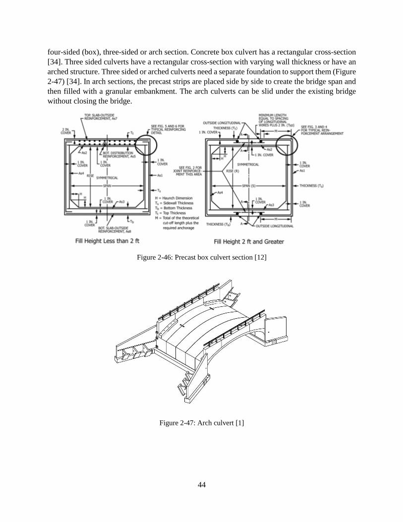
44
four-sided (box), three-sided or arch section. Concrete box culvert has a rectangular cross-section
[34]. Three sided culverts have a rectangular cross-section with varying wall thickness or have an
arched structure. Three sided or arched culverts need a separate foundation to support them (Figure
2-47) [34]. In arch sections, the precast strips are placed side by side to create the bridge span and
then filled with a granular embankment. The arch culverts can be slid under the existing bridge
without closing the bridge.
Figure 2-46: Precast box culvert section [12]
Figure 2-47: Arch culvert [1]
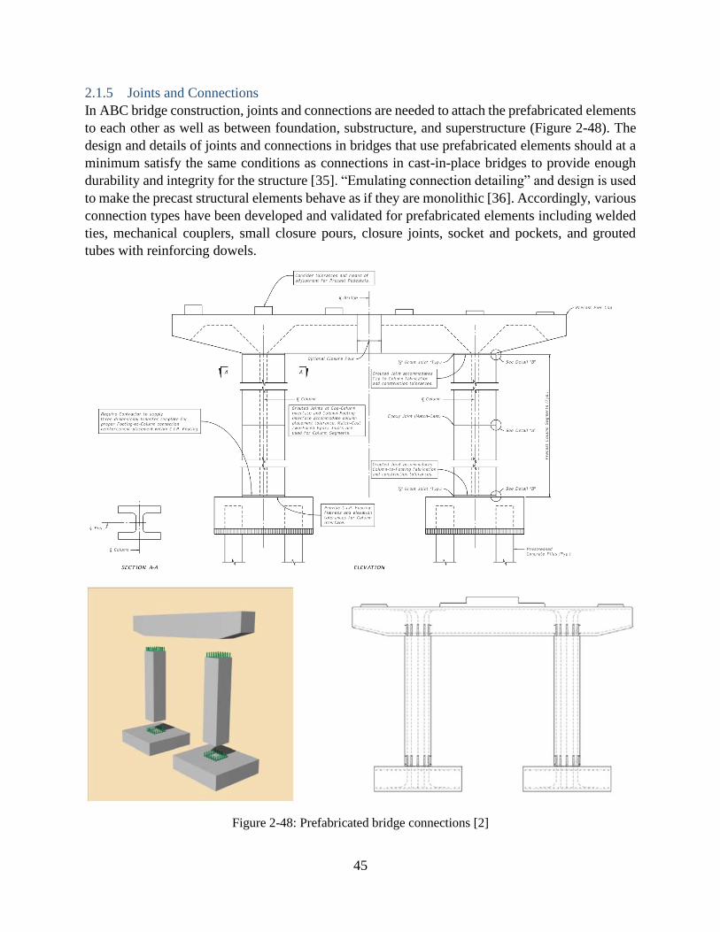
45
2.1.5 Joints and Connections
In ABC bridge construction, joints and connections are needed to attach the prefabricated elements
to each other as well as between foundation, substructure, and superstructure (Figure 2-48). The
design and details of joints and connections in bridges that use prefabricated elements should at a
minimum satisfy the same conditions as connections in cast-in-place bridges to provide enough
durability and integrity for the structure [35]. “Emulating connection detailing” and design is used
to make the precast structural elements behave as if they are monolithic [36]. Accordingly, various
connection types have been developed and validated for prefabricated elements including welded
ties, mechanical couplers, small closure pours, closure joints, socket and pockets, and grouted
tubes with reinforcing dowels.
Figure 2-48: Prefabricated bridge connections [2]
46
2.1.5.1 Superstructure element connections
Joints connecting deck elements to each other and deck to the piers or girders are generally referred
to as closure joints (Figure 2-49). The function of these joints is to prevent vertical movement of
panels and transfer traffic load [1]. This joint can experience normal load, shear load, and bending
moment.
Shear keys are used for connecting full-depth precast adjacent panels to each other. There are two
types of shear keys including non-grouted male-female and grouted female-to-female joint [2]. In
non-grouted joints, the longitudinal post-tensioning rebar is used to connect the panels and keep
them together (Figure 2-50). In this connection, some sealant or epoxy is used at the interface
before post-tensioning is applied. In grouted female to female joints, none-shrink grout is typically
used to fill the joint (Figure 2-51). This type of connection performs properly if no cracks occur in
the connection due to shrinkage and repeated service load, and if no water leakage occurs through
the joint [37]. Moreover, the longitudinal reinforcement in panels can be spliced or doweled within
the joints to distribute the live load from the traffic, and to resist shear and bending moment [2]
(Figure 2-52).
Pockets left in the precast panels, blockouts are used to connect the precast panel to concrete
girders. Reinforcement or shear studs extended out of the girder and embedded into the pockets
to transfer shear between two connected elements (Figure 2-53). This connection is easily
accessible. It can experience high shear and bending moment and little deformation. The
connection of precast deck panels to girders and piers can be established through linear closure
joints that also include headed steel studs [37]. Rectangular and V-shaped closure joint, with or
without reinforcement or post-tensioning are also used to connect deck panels to each other, girder,
and piers. Another type of connection that joins precast concrete girder and deck is with the use of
drilled holes. After placement of deck, a hole is drilled into the deck and girder to to provide a
conduit for dowel-type connection. This drilling is mostly not a problem for prestressed girders
because the girder bars are located at the bottom of girder [2].
In summary, according to the joints configuration, the most common closure joints are categorized
into five types [38]. These five categories are shown in Table 2-7. The first four shapes cover
“linear” joints, and the last shape covers “blockouts.” Linear joints refer to longitudinal and
transverse joints for connecting deck panels or decked beams to each other and to the girders, and
connecting deck panels to the abutment/piers. Blockouts are pocket-type joints mostly for
connecting deck panels to the girders [2].
In addition to the above common joints, other connecction types are also used for specific cases.
Welding is one type of connection that can be used to connect panels to steel girder. This
connection is preferable for ABC bridge construction because it can be erected quickly. Before
installation of the panel, a steel plate is placed in a specified location of the panel, and then the
steel girder and the panel are welded together in the field [2].
Prefabricated units can also be joined together using bolted connection. One use of the bolted
connection is for establishing transverse connection between modular double tee units. The
adjacent diaphragm plates are also bolted together [2].

47
One issue in the construction of superstructure is irregularity in the finished surface of panels due
to inconsistencies in the panels or their supporting members. One way to address this issue and
level the adjacent panels is to use a leveling device (Figure 2-54). In this case, a threaded socket
is cast in the corner of each panel. Then the bolt is threaded in the socket and wrench to adjust the
elevation of panels [5].
Figure 2-49: Examples of deck closure joints [2]
Figure 2-50: Non-grouted panel to panel (male-to-female) joint [37, 5]

48
Figure 2-51: Various type of female-to-female joint [37]
Figure 2-52: Longitudinal reinforcement [37]
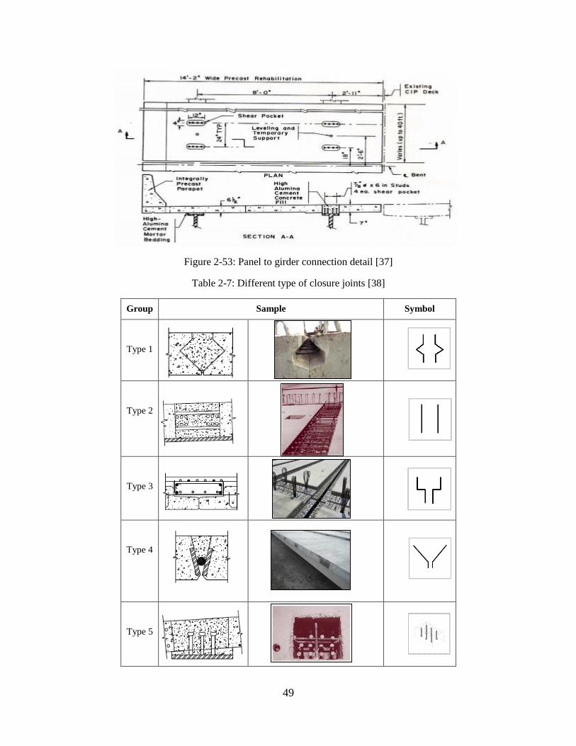
49
Figure 2-53: Panel to girder connection detail [37]
Table 2-7: Different type of closure joints [38]
Group Sample Symbol
Type 1
Type 2
Type 3
Type 4
Type 5

50
Figure 2-54: Leveling bolt [3]
2.1.5.2 Substructure element connections
Within a substructure, joints are used to connect columns, piers, or walls to a cap beam as well as
to the footing [2]. While it is easy to access the connections to the pier cap beam for inspection,
the connections to the footing can be covered. These connections can experience high shear and
bending moment, especially from lateral loading due to the earthquake. Additionally, in the
longitudinal direction, it may undergo considerable lateral loading due to high deformation from
thermal expansion of the deck slab [2].
Cap beam connection to column
Precast cap beam may connect to the cast-in-place column, a precast concrete column, steel pile,
or precast concrete pile. There are different methods to join the column to cap beam. The
connection of column to cap beam can form in the cap beam or along the column. In another
method, the cap beam can be welded to the column. A summary of different methods to connect
cap beam and columns are listed in Table 2-8.
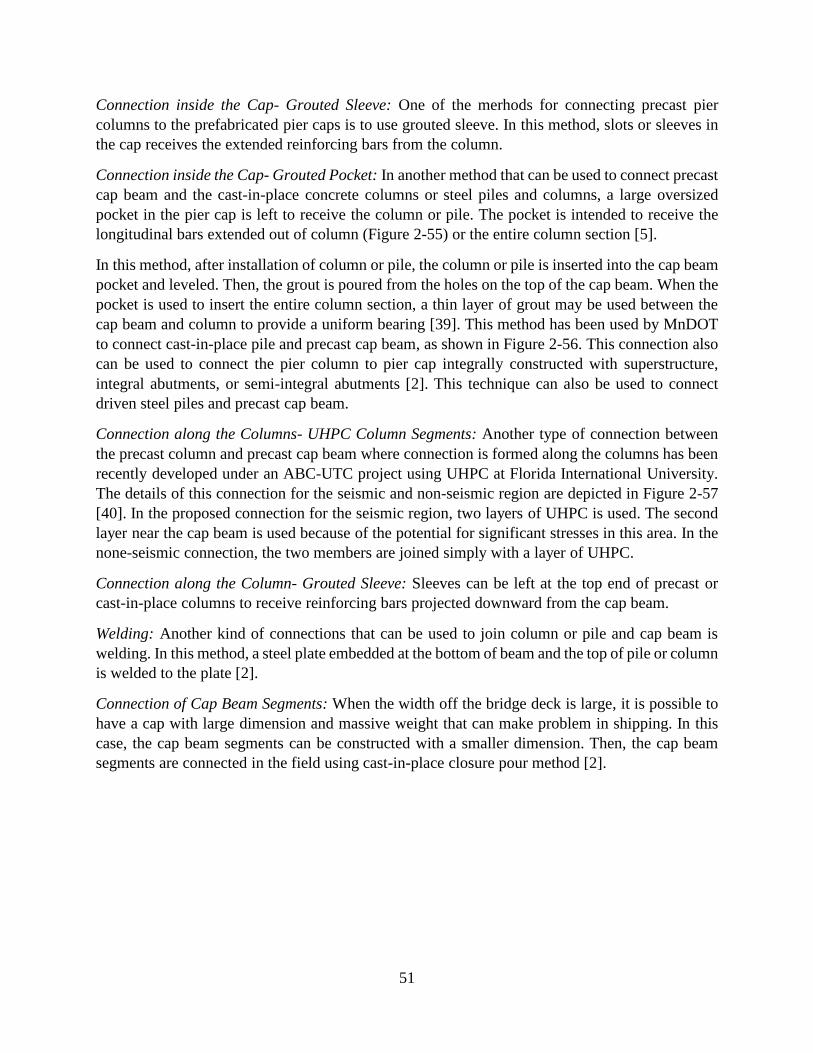
51
Connection inside the Cap- Grouted Sleeve: One of the merhods for connecting precast pier
columns to the prefabricated pier caps is to use grouted sleeve. In this method, slots or sleeves in
the cap receives the extended reinforcing bars from the column.
Connection inside the Cap- Grouted Pocket: In another method that can be used to connect precast
cap beam and the cast-in-place concrete columns or steel piles and columns, a large oversized
pocket in the pier cap is left to receive the column or pile. The pocket is intended to receive the
longitudinal bars extended out of column (Figure 2-55) or the entire column section [5].
In this method, after installation of column or pile, the column or pile is inserted into the cap beam
pocket and leveled. Then, the grout is poured from the holes on the top of the cap beam. When the
pocket is used to insert the entire column section, a thin layer of grout may be used between the
cap beam and column to provide a uniform bearing [39]. This method has been used by MnDOT
to connect cast-in-place pile and precast cap beam, as shown in Figure 2-56. This connection also
can be used to connect the pier column to pier cap integrally constructed with superstructure,
integral abutments, or semi-integral abutments [2]. This technique can also be used to connect
driven steel piles and precast cap beam.
Connection along the Columns- UHPC Column Segments: Another type of connection between
the precast column and precast cap beam where connection is formed along the columns has been
recently developed under an ABC-UTC project using UHPC at Florida International University.
The details of this connection for the seismic and non-seismic region are depicted in Figure 2-57
[40]. In the proposed connection for the seismic region, two layers of UHPC is used. The second
layer near the cap beam is used because of the potential for significant stresses in this area. In the
none-seismic connection, the two members are joined simply with a layer of UHPC.
Connection along the Column- Grouted Sleeve: Sleeves can be left at the top end of precast or
cast-in-place columns to receive reinforcing bars projected downward from the cap beam.
Welding: Another kind of connections that can be used to join column or pile and cap beam is
welding. In this method, a steel plate embedded at the bottom of beam and the top of pile or column
is welded to the plate [2].
Connection of Cap Beam Segments: When the width off the bridge deck is large, it is possible to
have a cap with large dimension and massive weight that can make problem in shipping. In this
case, the cap beam segments can be constructed with a smaller dimension. Then, the cap beam
segments are connected in the field using cast-in-place closure pour method [2].

52
Table 2-8: Different connections of cap beam and column
Type Connection method Usage
Formed in cap beam
Grouted sleeve -Connect precast cap beam to cast-
in-place or precast concrete column
Grouted pocket
-Connect precast cap beam and
precast or cast-in-place concrete
column
-Connect precast cap beam and steel
pile or column
Formed along the Columns
UHPC column
segment
-Connect precast cap beam and
precast concrete column
Grouted sleeve -Connect precast cap beam and
precast concrete column
Mechanical couplers -Connect precast column to to cap
beam
Other types Welding -Connect precast cap beam and steel
pile or column
Cap beam segments
Closure pour -Connect precast cap beam segments
Mechanical couplers -Connect precast cap beam segments
to create moment connection
Figure 2-55: Column to cap beam connection using grouted sleeve method [5]

53
Figure 2-56: Precast cap beam and cast-in-place column using grouted pocket [2]
Figure 2-57: a) Seismic and b) non-seismic detail of UHPC connection of precast column and precast cap
beam [40]
Footing connection to column
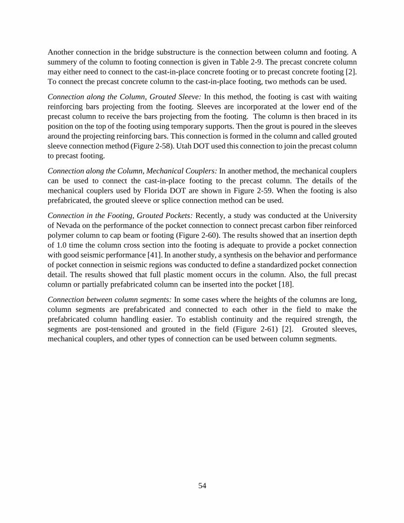
54
Another connection in the bridge substructure is the connection between column and footing. A
summery of the column to footing connection is given in Table 2-9. The precast concrete column
may either need to connect to the cast-in-place concrete footing or to precast concrete footing [2].
To connect the precast concrete column to the cast-in-place footing, two methods can be used.
Connection along the Column, Grouted Sleeve: In this method, the footing is cast with waiting
reinforcing bars projecting from the footing. Sleeves are incorporated at the lower end of the
precast column to receive the bars projecting from the footing. The column is then braced in its
position on the top of the footing using temporary supports. Then the grout is poured in the sleeves
around the projecting reinforcing bars. This connection is formed in the column and called grouted
sleeve connection method (Figure 2-58). Utah DOT used this connection to join the precast column
to precast footing.
Connection along the Column, Mechanical Couplers: In another method, the mechanical couplers
can be used to connect the cast-in-place footing to the precast column. The details of the
mechanical couplers used by Florida DOT are shown in Figure 2-59. When the footing is also
prefabricated, the grouted sleeve or splice connection method can be used.
Connection in the Footing, Grouted Pockets: Recently, a study was conducted at the University
of Nevada on the performance of the pocket connection to connect precast carbon fiber reinforced
polymer column to cap beam or footing (Figure 2-60). The results showed that an insertion depth
of 1.0 time the column cross section into the footing is adequate to provide a pocket connection
with good seismic performance [41]. In another study, a synthesis on the behavior and performance
of pocket connection in seismic regions was conducted to define a standardized pocket connection
detail. The results showed that full plastic moment occurs in the column. Also, the full precast
column or partially prefabricated column can be inserted into the pocket [18].
Connection between column segments: In some cases where the heights of the columns are long,
column segments are prefabricated and connected to each other in the field to make the
prefabricated column handling easier. To establish continuity and the required strength, the
segments are post-tensioned and grouted in the field (Figure 2-61) [2]. Grouted sleeves,
mechanical couplers, and other types of connection can be used between column segments.
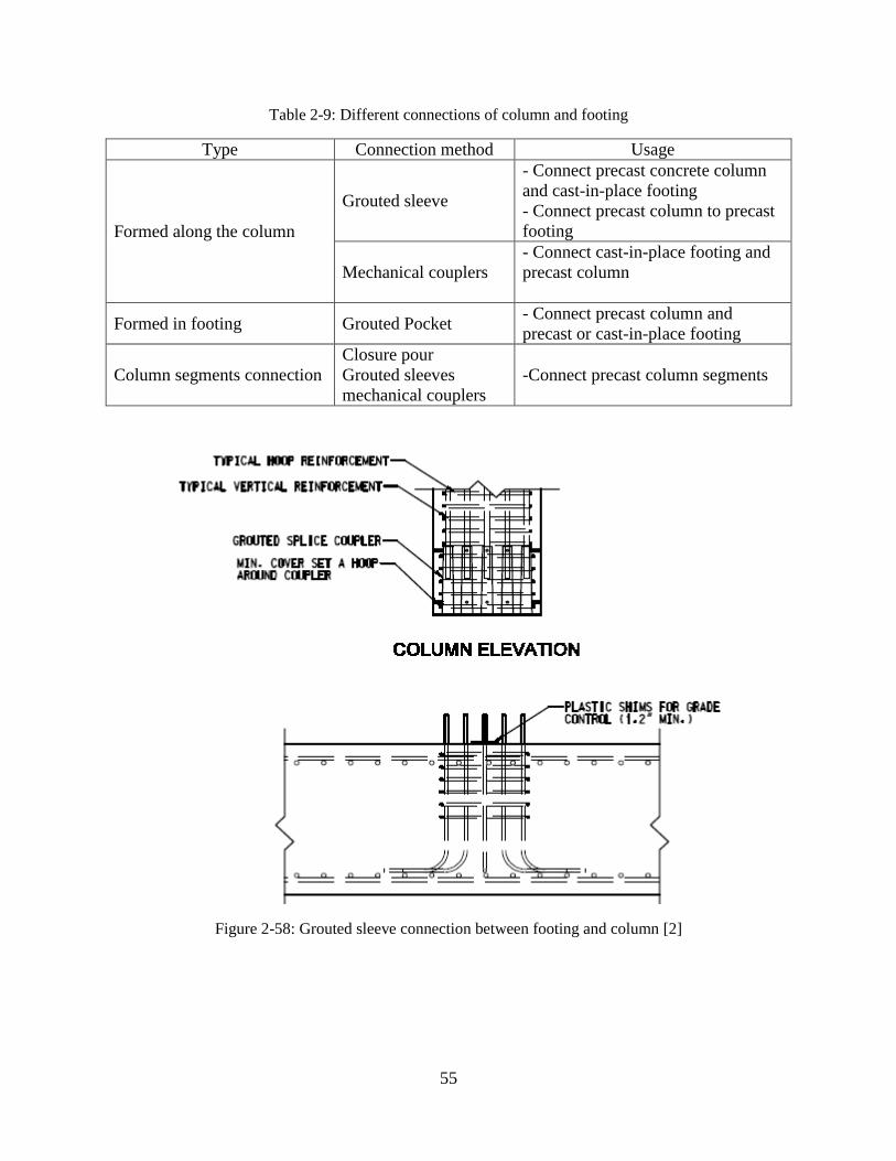
55
Table 2-9: Different connections of column and footing
Type Connection method Usage
Formed along the column
Grouted sleeve
- Connect precast concrete column
and cast-in-place footing
- Connect precast column to precast
footing
Mechanical couplers
- Connect cast-in-place footing and
precast column
Formed in footing Grouted Pocket - Connect precast column and
precast or cast-in-place footing
Column segments connection
Closure pour
Grouted sleeves
mechanical couplers
-Connect precast column segments
Figure 2-58: Grouted sleeve connection between footing and column [2]

56
Figure 2-59: Cast-in-place footing to precast column connection using mechanical couplers [2]
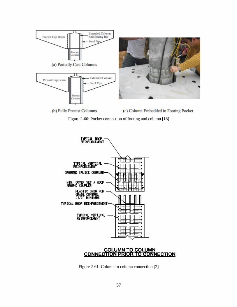
57
Figure 2-60: Pocket connection of footing and column [18]
Figure 2-61: Column to column connection [2]

58
Abutment and wall systems connections
Abutment systems including cantilever abutment, spill-through abutment, precast wall, integral
and semi-integral abutments are other components of the bridge that can be constructed off-site
and connected to each other in the field. The connections that can be used to join the abutment
components together are summarized in Table 2-10.
Closure pour: Cast-in-place closure pour is the connection method that can be used to connect the
integral abutments elements and join abutment to superstructure. The disadvantage of this method
is its high cost due to use of high performance concrete as a closure pour. Figure 2-62 depict this
connection details [42].
Grouted Sleeve/Splice couplers: Grouted splice couplers can be used to connect precast elements
like abutment stem and footing [2]. This connection type has been used by New Hampshire DOT
to connect all of the abutment elements and is shown in Figure 2-63. In the cantilever abutment
system, the connection of backwall to abutment stem is also needed (Figure 2-64, 2-65). Backwall
is used to support the soil behind the beam ends. To connect backwall to abutment stem, the
grouted splice couplers connection, same as abutment stem to footing connection, can be used.
Also, other types of connections based on the conditions can be used. Another connection in the
cantilever system is precast breastwall (checkwall) to abutment stem. Breastwall in this system is
used as a decorative element at the corner of the abutment to connect the end of the beams. To
attach precast breastwall to abutment stem, grouted splice couplers or other kind of connections
based on the conditions can be used. In another type of abutment system, spill-through abutment,
the same type of connections as that used for cantilever abutment can be used [2]. Other connecting
methods of the precast wall to the precast footing include grouted shear key and using mechanical
connectors. Recently, a study conducted by Iowa State University evaluated durability, strength,
and application of grouted couplers in the integral abutments. The grouted reinforcing bar and pile
couplers were evaluated, and this connection detail was established [17, 42].
Grouted Pocket Connection: In some cases, the abutment stem or cap connect directly to steel piles
or precast concrete piles. One way to establish this connection is by embedding piles into
prefabricated pockets in the abutment stem and grouting the space between (Figure 2-66, 2-67).
Welded Plate Connection: To connect the steel piles directly to abutment, steel plates can be
anchored in the abutment, and welded to the piles.
Steel bar dowels connection: To make the abutment integral with the superstructure, steel bar
dowels can be used between the abutment stem and abutment cap that is made integral with the
superstructure. Figure 2-68 shows a dowel connection.
Small closure pour: In some cases, because of the abutment dimensions and shipping limitations,
the abutment cap may be prefabricated in segments [2]. These segments can be attached to each
other in the field. To connect them, the match cast and post-tensioning method which is used by
Maine DOT or a small closure pour technique can be used (Figure 2-69).
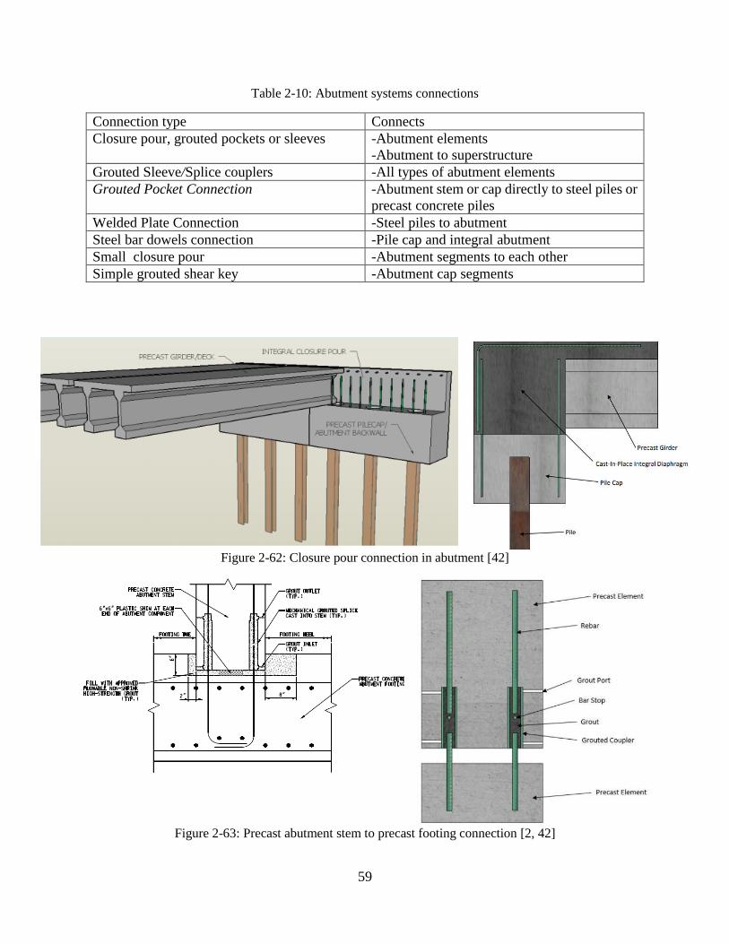
59
Table 2-10: Abutment systems connections
Connection type Connects
Closure pour, grouted pockets or sleeves -Abutment elements
-Abutment to superstructure
Grouted Sleeve/Splice couplers -All types of abutment elements
Grouted Pocket Connection -Abutment stem or cap directly to steel piles or
precast concrete piles
Welded Plate Connection -Steel piles to abutment
Steel bar dowels connection -Pile cap and integral abutment
Small closure pour -Abutment segments to each other
Simple grouted shear key -Abutment cap segments
Figure 2-62: Closure pour connection in abutment [42]
Figure 2-63: Precast abutment stem to precast footing connection [2, 42]
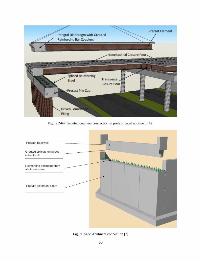
60
Figure 2-64: Grouted couplers connection in prefabricated abutment [42]
Figure 2-65: Abutment connection [2]

61
Figure 2-66: Precast integral abutment connection to steel pile [2]
Figure 2-67: Precast integral abutment connection to steel pile [2]
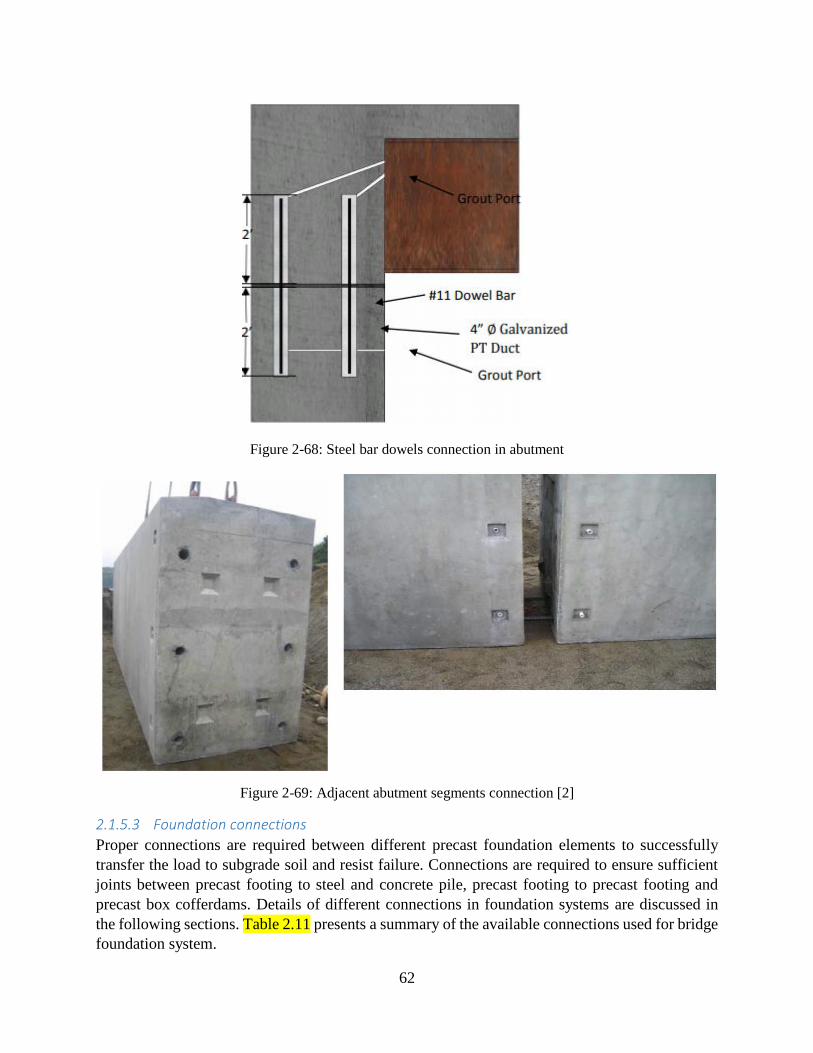
62
Figure 2-68: Steel bar dowels connection in abutment
Figure 2-69: Adjacent abutment segments connection [2]
2.1.5.3 Foundation connections
Proper connections are required between different precast foundation elements to successfully
transfer the load to subgrade soil and resist failure. Connections are required to ensure sufficient
joints between precast footing to steel and concrete pile, precast footing to precast footing and
precast box cofferdams. Details of different connections in foundation systems are discussed in
the following sections. Table 2.11 presents a summary of the available connections used for bridge
foundation system.

63
Footing and Pile Systems: Prefabricated piles are most commonly used for bridges by state DOTs
whereas the concept of prefabricated footings is comparatively new. The connection between the
footing and pile system is important to transfer the load successfully.
Precast Footing to Subgrade Connections: The primary problem with the use of precast concrete
footing is to properly seat the footing on the subgrade. Settlement or rocking of the foundation
may result from inadequate seating on the subgrade. It can be eliminated by placing a flowable
concrete or grout under the footing or by using leveling bolts on the corners to lift the footing
above the subgrade. In such cases, low grade concrete or flowable fill can be used as this is not a
structural element. A sub-footing can also be used to create a level area for footings construction
in bedrock [2]. Figure 2.70 presents the connections between precast footing and subgrade
materials.
Figure 2-70 Details of Precast footing to subgrade Connection [2]
Precast Footing to Precast Footing Connections: The connection between adjacent footings
elements may or may not need to be a structural connection, depending on the design. A simple
grouted shear key can be used if there is no structural requirement for the connection. However, a
small closure pour connection can be used if a moment connection is required (Figure 2.71). For
this purpose, reinforcing steels are extended from footing elements and grout is poured in the
formed area created by the two footing elements and the subgrade [2]. Figure 2.72 presents a
photograph of installation of a precast concrete footing with grouted shear connection on concrete
sub-footing.

64
Figure 2-71 Precast concrete footing to precast concrete footing connection [2]
Figure 2-72 Installation of a precast concrete footing with grouted shear connection on concrete sub-
footing [2]

65
Precast Footing to Steel Pile Connection: The connection details for precast concrete pier caps to
steel pile mentioned in Section 2.5.1.2 can be used for precast footing to steel pile connections.
However, uplift on the piles or moment capacity requirement may create problems for such
connections. The pile end reinforcing steel can be welded and embedded in a closure pour to
provide enough uplift capacity for this connection (Figure 2.73). Also, embedment of the pile top
by at least 12 inches into the footing will help to achieve adequate moment capacity for this
connection [2].
Figure 2-73 Connection between precast concrete footing and steel pile with uplift
Precast Footing to Precast Concrete Piles: Similar to steel pile connections, several states have
developed connection details for precast concrete piles connected to precast concrete pier bents.
There have also been concrete pile connection details developed for integral abutment bridges. For
example, Florida DOT has developed a connection for a hollow precast concrete pile to a precast
footing to develop full moment capacity of the pile (Figure 2.74). The connection consists of a
large blockout in the footing where a reinforcing steel cage is installed between the pile top and
the blockout [2].

66
Figure 2-74 Connection details between concrete square pile and pile cap [2]
Precast Footing to Cast-in-place Pile or Drilled Shaft Connections: Till now, no connections
between precast footing to cast-in-place piles or drilled shafts connected to precast concrete
footings have been developed by any state DOTs. However, the precast footing to concrete pile
connection details could be adapted for use with cast-in-place concrete piles or drilled shafts.
Precast Pile to Precast Pile Connection: To accommodate variations in subsurface conditions,
pile lengths for some pile types can be easily adjusted and spliced in the field. Many state DOTs
have developed standard details for connecting precast driven piles that need to be spliced. Precast
concrete pile industry has developed standard pile splicing details [43]. The Florida DOT has

67
developed a detail for splicing hollow square prestressed concrete piles (Figure 2.75). These details
consist of a reinforced concrete closure pour between pile elements.
Figure 2-75 Connection between concrete square piles using splice
Precast Pier Box Cofferdams: Construction of the pier footings on piles is one of the biggest
challenges during construction of piers over water. Precast concrete pier box is used to dewater
the area where the drilled shaft connects to the bridge footing. Figure 2.76 presents a photograph
of the new Providence River Bridge in Providence, Rhode Island where precast concrete pier boxes
were hung from the 8-foot diameter drilled shafts to create dry space. The connection between the
precast box and the drilled shaft was sealed with a small tremie pour around the drilled shaft.
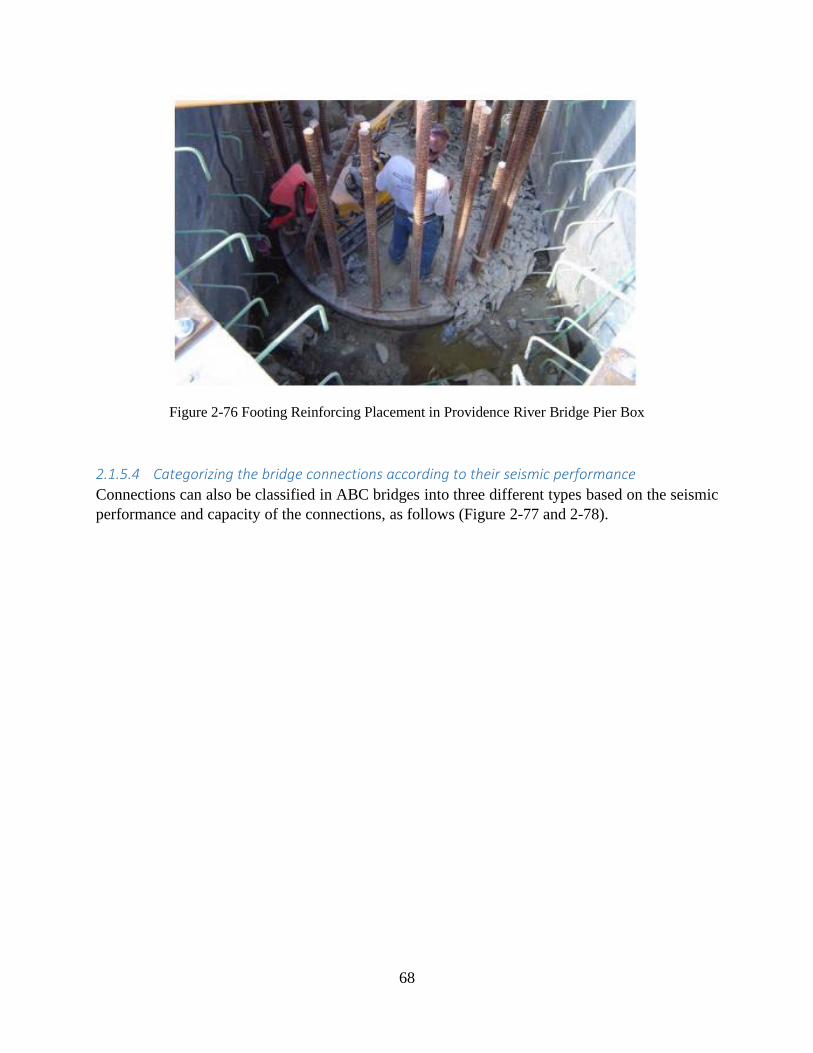
68
Figure 2-76 Footing Reinforcing Placement in Providence River Bridge Pier Box
2.1.5.4 Categorizing the bridge connections according to their seismic performance
Connections can also be classified in ABC bridges into three different types based on the seismic
performance and capacity of the connections, as follows (Figure 2-77 and 2-78).

69
Figure 2-77: Connection locations based on prefabricated members plastic hinge zone [35]
Figure 2-78: Connection locations based on their seismic performance [35]
Capacity-protected (CP) connection: This kind of connection has a cyclic strength higher
than the strength of the members that are connected. In this case, the inelastic deformation
occurs in the members that are connected.
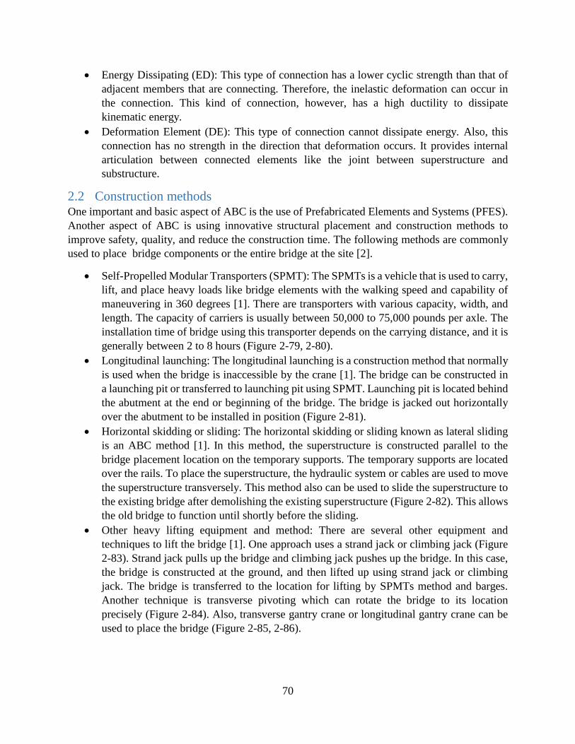
70
Energy Dissipating (ED): This type of connection has a lower cyclic strength than that of
adjacent members that are connecting. Therefore, the inelastic deformation can occur in
the connection. This kind of connection, however, has a high ductility to dissipate
kinematic energy.
Deformation Element (DE): This type of connection cannot dissipate energy. Also, this
connection has no strength in the direction that deformation occurs. It provides internal
articulation between connected elements like the joint between superstructure and
substructure.
2.2 Construction methods One important and basic aspect of ABC is the use of Prefabricated Elements and Systems (PFES).
Another aspect of ABC is using innovative structural placement and construction methods to
improve safety, quality, and reduce the construction time. The following methods are commonly
used to place bridge components or the entire bridge at the site [2].
Self-Propelled Modular Transporters (SPMT): The SPMTs is a vehicle that is used to carry,
lift, and place heavy loads like bridge elements with the walking speed and capability of
maneuvering in 360 degrees [1]. There are transporters with various capacity, width, and
length. The capacity of carriers is usually between 50,000 to 75,000 pounds per axle. The
installation time of bridge using this transporter depends on the carrying distance, and it is
generally between 2 to 8 hours (Figure 2-79, 2-80).
Longitudinal launching: The longitudinal launching is a construction method that normally
is used when the bridge is inaccessible by the crane [1]. The bridge can be constructed in
a launching pit or transferred to launching pit using SPMT. Launching pit is located behind
the abutment at the end or beginning of the bridge. The bridge is jacked out horizontally
over the abutment to be installed in position (Figure 2-81).
Horizontal skidding or sliding: The horizontal skidding or sliding known as lateral sliding
is an ABC method [1]. In this method, the superstructure is constructed parallel to the
bridge placement location on the temporary supports. The temporary supports are located
over the rails. To place the superstructure, the hydraulic system or cables are used to move
the superstructure transversely. This method also can be used to slide the superstructure to
the existing bridge after demolishing the existing superstructure (Figure 2-82). This allows
the old bridge to function until shortly before the sliding.
Other heavy lifting equipment and method: There are several other equipment and
techniques to lift the bridge [1]. One approach uses a strand jack or climbing jack (Figure
2-83). Strand jack pulls up the bridge and climbing jack pushes up the bridge. In this case,
the bridge is constructed at the ground, and then lifted up using strand jack or climbing
jack. The bridge is transferred to the location for lifting by SPMTs method and barges.
Another technique is transverse pivoting which can rotate the bridge to its location
precisely (Figure 2-84). Also, transverse gantry crane or longitudinal gantry crane can be
used to place the bridge (Figure 2-85, 2-86).

71
Conventional cranes: The conventional crane can be used to install and place the
prefabricated bridge elements including footings, pier columns, pier cap, girders, and deck
panels (Figure 2-87) [1].
Figure 2-79: SPMTs configuration [1]
Figure 2-80: SPMTs bridge move [1]
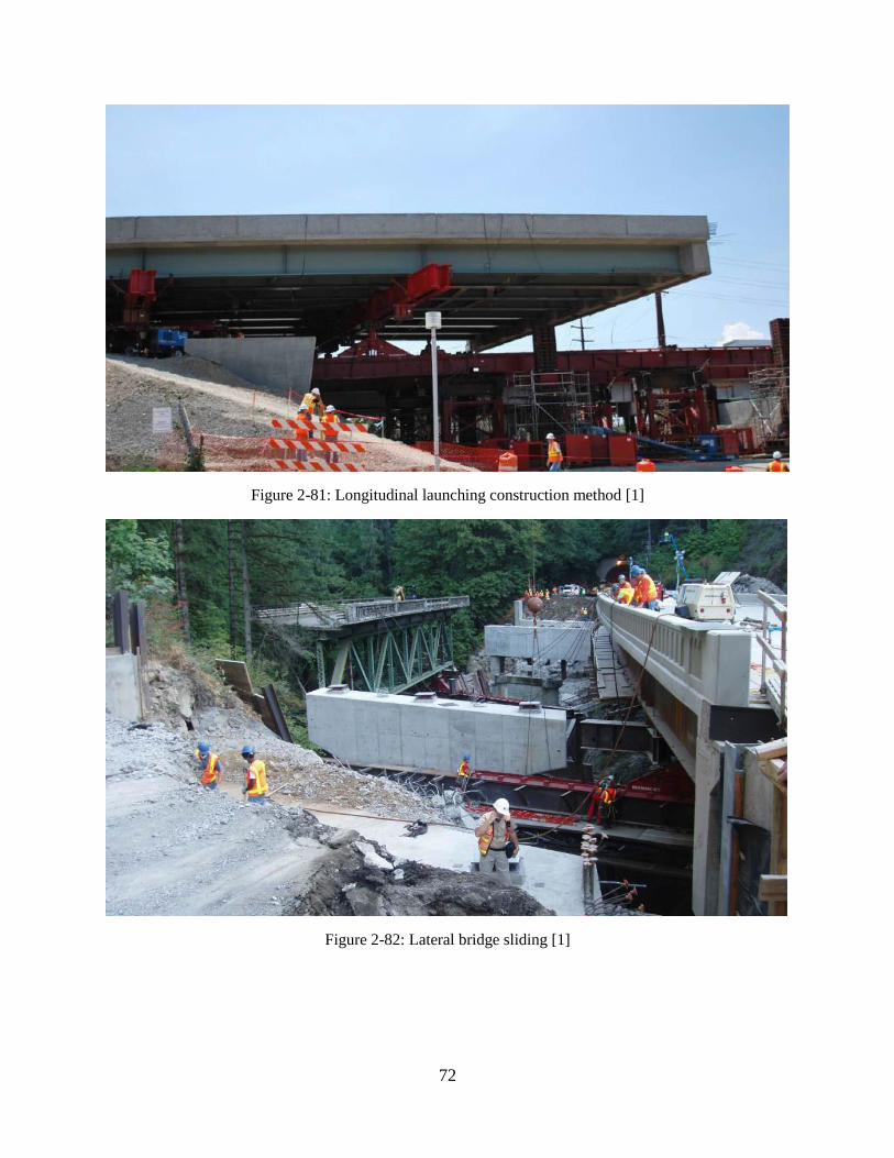
72
Figure 2-81: Longitudinal launching construction method [1]
Figure 2-82: Lateral bridge sliding [1]

73
Figure 2-83: Jack lifting of the bridge [1]
Figure 2-84: Vertical axis pivot [1]
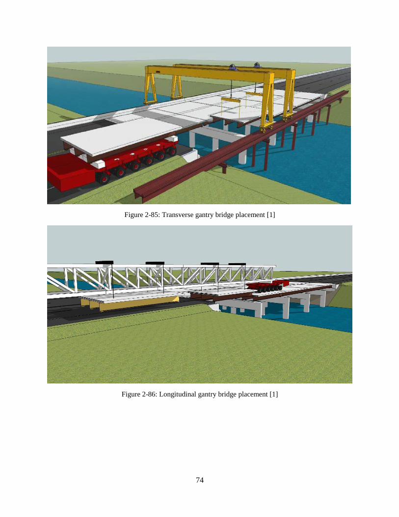
74
Figure 2-85: Transverse gantry bridge placement [1]
Figure 2-86: Longitudinal gantry bridge placement [1]

75
Figure 2-87: Bridge placement using conventional cranes
2.3 Potential Issues with Design and Construction At a minimum, the bridge design and construction should emulate the conventional bridge
construction and design [2]. To design the ABC elements, the AASHTO LRFD structural
specification design should be followed. The design and analysis of ABC connections are also
according to the AASHTO specification design for mechanical reinforcing devices. It requires that
the device resist 125% of yield strength of the reinforcing bar [44]. However, the AASHTO
specification does not cover all the aspects of ABC design and construction. Another critical issue
in ABC is lifting and moving of large-scale elements. In this case, the location of supports and
stiffness of supports used in moving and lifting of elements in the prefabricated elements should
be defined. However, the AASHTO specification does not cover this issue. Utah DOT studied the
effect of dynamic load due to movement of prefabricated elements. Although that study was
limited, it was concluded that the dead load of members should be considered 15% more than their
actual weight due to the effect of the dynamic load from elements movement [2]. According to a
survey, the most common concern of states is lack of standard in the construction and design of
ABC bridges [45], the high cost of ABC, inexperienced contractors, and staging of ABC elements.
Exceptions also exist. The Hawaii DOT demonstrated that ABC has a lower cost than cast-in-place
projects. Also, there is ongoing research to define the total construction cost of ABC including
users cost and long-term maintenance costs [46]. The issues in the construction and design of ABC
elements and connections are summarized below.
Another issue that needs to be addressed is related to the structural analysis method of the bridge.
It is critical to determine if there is any changes in the type of analysis method and load distribution
of the structure because of or as a consequence of implementing method of accelerated bridge
construction. This issue should be considered for different prefabricated elements and
76
configuration. Also, the loads associated with the lifting and supporting point of prefabricated
elements during their erection including dynamic effects should be defined [47].
2.3.1 Superstructure
New Mexico DOT used the full depth precast deck in a project. The problem that DOT encountered
was that fabricators, contractors, and designers did not have enough experience. Due to this
problem, the fabrication, designing, and placement of the project took very long [45]. There is an
ongoing research about the performance of full-depth precast deck concrete to address the full-
depth deck construction concerns [48]. In this study, the actual in-service performance of full-
depth precast panel will be compared to the cast-in-place deck method in addition to provide a
successful construction detail for this member.
2.3.2 Substructure
According to a survey, pier cap durability and behavior in seismic condition is one of the crucial
issues that has limited the use of ABC. California DOT described this issue as the one needs to be
addressed [45]. TX-DOT assessed different connections of grout pocket, grouted vertical ducts,
grouted sleeve couplers, and bolted connections that can be used for the cap beams [49].
Nevertheless, the performance of these connections was not investigated in the seismic regions.
Therefore, use of these connections in seismic areas needs to be investigated. Moreover, the
sufficient tolerance of cap beam duct and its diameter is one of the primary concerns in the
placement of cap beam [49]. Another issue mentioned in the study was the durability of grout that
is poured in the pockets. The grout should have sulfate and freeze-thaw resistance.
2.3.3 Foundation
Selection of proper foundation is always a challenge for bridge structure. It was found that some
states often select deep foundation even though spread footings are technically feasible and cost
effective [50]. However, Virginia DOT suggested not to use deep foundations indiscriminately for
all subsurface conditions [24]. A survey conducted by Georgia Southern University indicate that
few DOTs are reluctant to use precast footings because of concerns about connection durability
[45]. Therefore, more research is needed for designing durable connections between precast
footing elements. Also, concerns about the quality control and quality assurance as well as pile
integrity of CFA piles limit their’ use [27]. Some other challenges in foundation construction are
retention of excavated earth, construction in deep water, etc. [1].
2.3.4 Joints and Connections
One type of joint used for connecting columns to the footing or connect the column to pier cap is
mechanical reinforcing splice or couplers (splice couplers connection method). AASHTO
structural specification does not allow the use of this connection in the plastic hinge zone of the
column in seismic regions. However, the ACI building code allows the use of this connection in
seismic areas. Therefore, this connection needs more research so that it can be permitted by
AASHTO for use in seismic regions [35].
Corrugated voids in the prefabricated elements are used to connect the elements to each other.
These voids can reduce the weight of elements during shipping and transfer shear and moment
between connected elements. AASHTO specification does not define the required cover for this

77
connection. This question needs some more research to define the required cover in the
construction of prefabricated elements in different conditions [1].
A survey was conducted by Georgia Southern University about the implementation of ABC and
the issues encountered by state DOTs [45]. In that survey, most of the state DOTs had concern
about the durability and long-term performance of UHPC closure pours. There is ongoing research
at ABC-UTC to study the long-term corrosion protection provided by UHPC used in joints and
substructure elements [51].
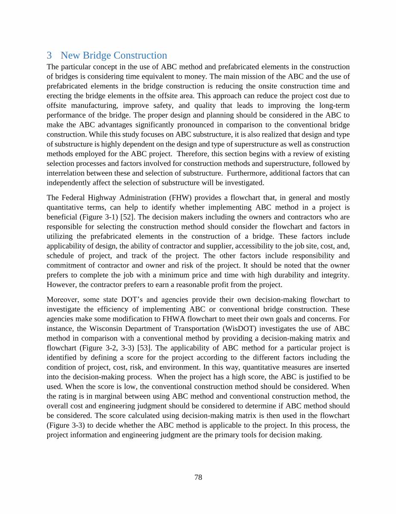
78
3 New Bridge Construction The particular concept in the use of ABC method and prefabricated elements in the construction
of bridges is considering time equivalent to money. The main mission of the ABC and the use of
prefabricated elements in the bridge construction is reducing the onsite construction time and
erecting the bridge elements in the offsite area. This approach can reduce the project cost due to
offsite manufacturing, improve safety, and quality that leads to improving the long-term
performance of the bridge. The proper design and planning should be considered in the ABC to
make the ABC advantages significantly pronounced in comparison to the conventional bridge
construction. While this study focuses on ABC substructure, it is also realized that design and type
of substructure is highly dependent on the design and type of superstructure as well as construction
methods employed for the ABC project. Therefore, this section begins with a review of existing
selection processes and factors involved for construction methods and superstructure, followed by
interrelation between these and selection of substructure. Furthermore, additional factors that can
independently affect the selection of substructure will be investigated.
The Federal Highway Administration (FHW) provides a flowchart that, in general and mostly
quantitative terms, can help to identify whether implementing ABC method in a project is
beneficial (Figure 3-1) [52]. The decision makers including the owners and contractors who are
responsible for selecting the construction method should consider the flowchart and factors in
utilizing the prefabricated elements in the construction of a bridge. These factors include
applicability of design, the ability of contractor and supplier, accessibility to the job site, cost, and,
schedule of project, and track of the project. The other factors include responsibility and
commitment of contractor and owner and risk of the project. It should be noted that the owner
prefers to complete the job with a minimum price and time with high durability and integrity.
However, the contractor prefers to earn a reasonable profit from the project.
Moreover, some state DOT’s and agencies provide their own decision-making flowchart to
investigate the efficiency of implementing ABC or conventional bridge construction. These
agencies make some modification to FHWA flowchart to meet their own goals and concerns. For
instance, the Wisconsin Department of Transportation (WisDOT) investigates the use of ABC
method in comparison with a conventional method by providing a decision-making matrix and
flowchart (Figure 3-2, 3-3) [53]. The applicability of ABC method for a particular project is
identified by defining a score for the project according to the different factors including the
condition of project, cost, risk, and environment. In this way, quantitative measures are inserted
into the decision-making process. When the project has a high score, the ABC is justified to be
used. When the score is low, the conventional construction method should be considered. When
the rating is in marginal between using ABC method and conventional construction method, the
overall cost and engineering judgment should be considered to determine if ABC method should
be considered. The score calculated using decision-making matrix is then used in the flowchart
(Figure 3-3) to decide whether the ABC method is applicable to the project. In this process, the
project information and engineering judgment are the primary tools for decision making.

79
In summary, in the case of new bridge construction, the designer has the freedom to select the most
appropriate system for implementation. Accordingly, the designer is not constrained by an existing
substructure.
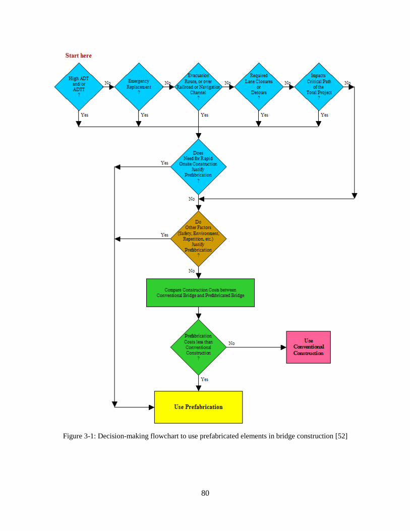
80
Figure 3-1: Decision-making flowchart to use prefabricated elements in bridge construction [52]
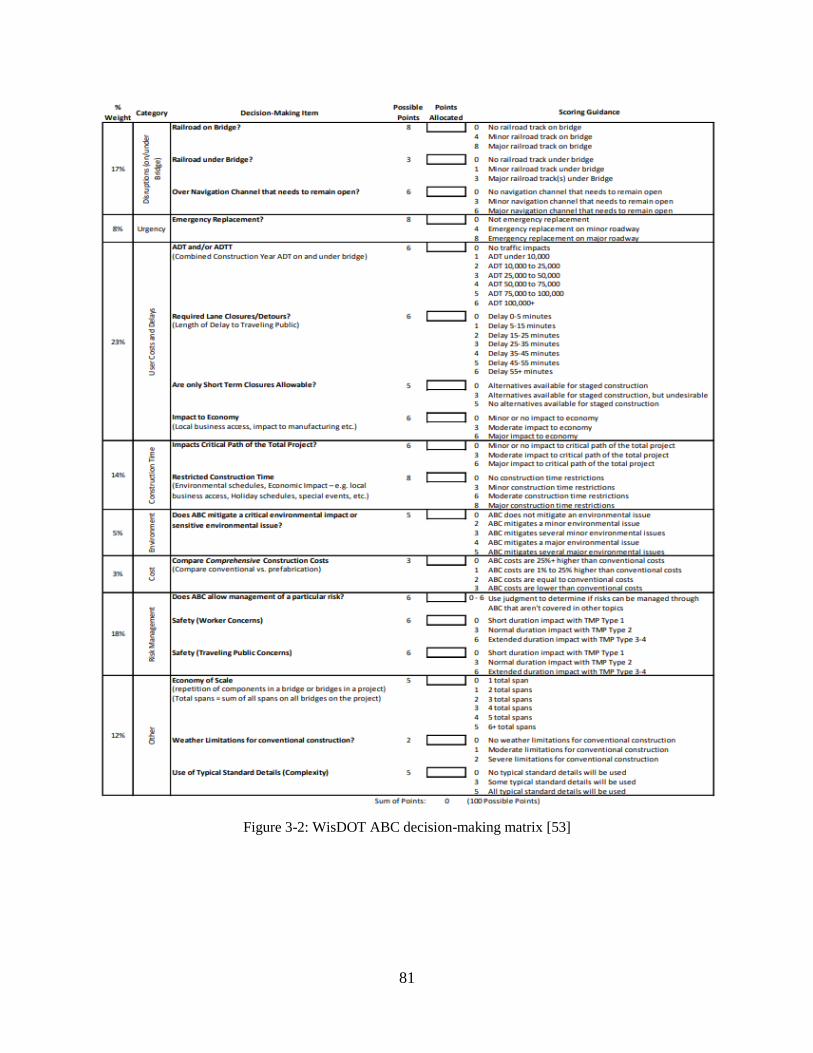
81
Figure 3-2: WisDOT ABC decision-making matrix [53]
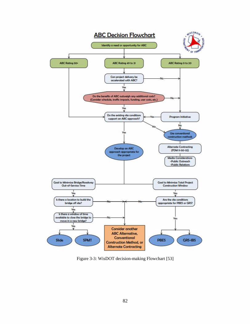
82
Figure 3-3: WisDOT decision-making Flowchart [53]
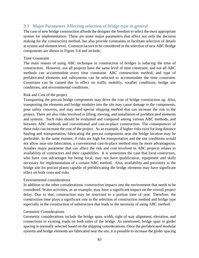
83
3.1 Major Parameters Affecting selection of bridge type in general The case of new bridge construction affords the designer the freedom to select the most appropriate
system for implementation. There are some major parameters that affect not only the decision
making for the construction method, but also provide constraints or facilitate selection of details
at system and element level. Common factors to be considered in the selection of new ABC Bridge
components are shown in Figure 3-4 and include;
Time Constraint
The main reason of using ABC technique in construction of bridges is reducing the time of
construction. However, not all projects have the same level of time constraint, and not all ABC
methods can accommodate every time constraint. ABC construction method, and type of
prefabricated elements and subsystems can be selected to accommodate the time constraint.
Constrains can be caused due to effect on traffic mobility, weather conditions, bridge site
conditions, and environmental conditions.
Risk and Cost of the project
Transporting the precast bridge components may drive the cost of bridge construction up. Also,
transporting the elements and bridge modules into the site may cause damage to the components,
pose safety concerns, and may need special shipping method that can increase the risk to the
project. There are also risks involved in lifting, moving, and installation of prefabricated elements
and systems. Such risks should be evaluated and compared among various ABC methods, and
between ABC methods and conventional and cast-in-place construction. The consequences of
these risks can increase the cost of the project. As an example, if higher risks exist for long distance
hauling and transportation, fabricating the precast components near the bridge location may be
preferable. In the same manner, if risks are high for transportation and the site conditions would
not allow near-site fabrication, a conventional cast-in-place method may be more advantageous.
Another major parameter that can affect the risk and cost involved in ABC projects relates to
availability of contractors and their capabilities. It is sometimes the case that local contractors,
who have cost advantages for being local, may not have qualification, equipment and skills
necessary for implementation of a certain ABC method. Also, availability and proximity to the
bridge site for precast plants capable of prefabricating the bridge elements may have significant
effect on both costs and risks.
Environmental considerations
In addition to the other considerations, construction impacts into the environment that needs to be
considered. Water activities, as an example, may have a significant impact on the overall project
delay. Due to that, construction may be restricted to a portion time of year. Therefore, the
construction time plays a significant role in the selection of construction method and bridge type
especially in the construction of substructure that leads to the necessity of using ABC method.
Geometric Considerations
Geometric considerations include the bridge span, width, right of way alignment, elevation, and
connections to existing roads on both sides of the bridge. As mentioned, bridge span or girder
spacing is normally selected based on the shipping considerations. Once the prefabricated modular
systems and bridge elements are fabricated near the site, it is possible to increase the girder spacing

84
over 130 ft. For bridge span up to 130 ft. the pre-tensioning method without the post-tensioning
method is used in the site. Once the bridge span is over 130 ft., the post-tensioning technique needs
to be used to extend the bridge span length [47]. In the case of substructure elements, when the
weight of elements and their shipping is in concern, using element segments and connecting them
on the site is the option.
Site Condition and Accessibility
In addition to the geometric and structural requirements that come to play in conventional bridge
design, additional consideration must be given to the space needed to manufacture large parts of
the bridge on-site or nearby the bridge final position and the space necessary to maneuver such
large elements to their final position. Site considerations also include the specifics of the bridge
site, such as local space available for erection and assembly of bridge components, existence of
deep water or rapid currents, adjacent property use and setbacks, width and vertical clearance of
roads leading to the project site. If water navigation is used to transport bridge elements, the width
and depth of water in the area are important site conditions. It also includes human activities,
driving habits, and availability of alternative transportation facility in the area. Such factors impact
the space available for the project and may favor specific construction types. For instance, the
existence of steep slopes may limit the feasibility of transportation of large bridge segments or
may require special equipment to allow bridge transportation and erection. When there is a
limitation in site accessibility, using the systems with smaller sizes elements are preferable.
Design Constraints and Considerations
In the case of new bridge construction, the design considerations include the number of spans,
span length, type of support, type of bridge structure, connection type, seismicity of the bridge
location, foundation, and layout of bridge roadway connection with other roads. In some instances
for example, implementing a joint less bridge design, full moment connection between bridge
members, integral abutments or similar considerations can provide higher integrity and durability
for the bridge when compared to other designs.
Compatibility between Superstructure and Substructure, and between Substructure and Foundation
In addition to geometric compatibility, the bridge elements and units are expected to be compatible
in design and construction with each other. For instance, the performance anticipated for
connection between super- and substructure may favor or limit the use of one or another type of
substructure.
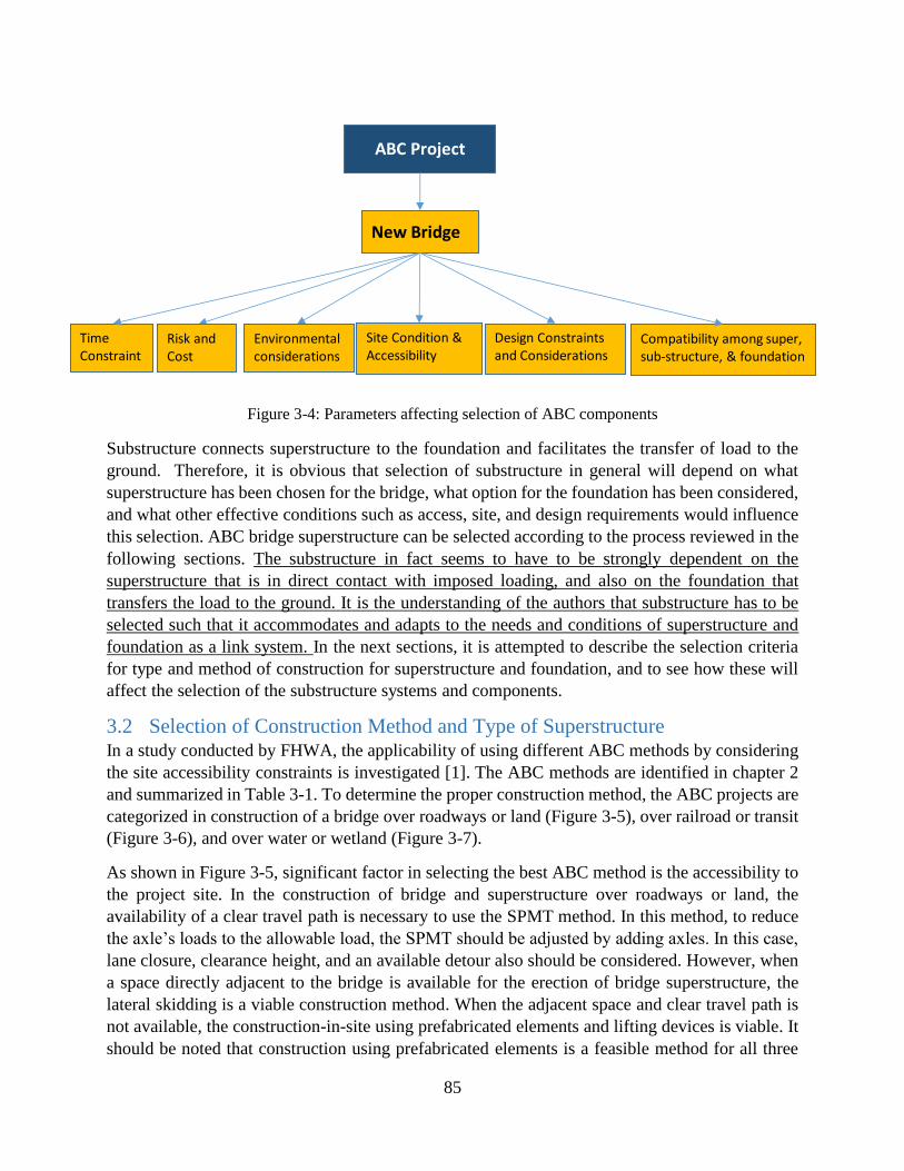
85
Figure 3-4: Parameters affecting selection of ABC components
Substructure connects superstructure to the foundation and facilitates the transfer of load to the
ground. Therefore, it is obvious that selection of substructure in general will depend on what
superstructure has been chosen for the bridge, what option for the foundation has been considered,
and what other effective conditions such as access, site, and design requirements would influence
this selection. ABC bridge superstructure can be selected according to the process reviewed in the
following sections. The substructure in fact seems to have to be strongly dependent on the
superstructure that is in direct contact with imposed loading, and also on the foundation that
transfers the load to the ground. It is the understanding of the authors that substructure has to be
selected such that it accommodates and adapts to the needs and conditions of superstructure and
foundation as a link system. In the next sections, it is attempted to describe the selection criteria
for type and method of construction for superstructure and foundation, and to see how these will
affect the selection of the substructure systems and components.
3.2 Selection of Construction Method and Type of Superstructure In a study conducted by FHWA, the applicability of using different ABC methods by considering
the site accessibility constraints is investigated [1]. The ABC methods are identified in chapter 2
and summarized in Table 3-1. To determine the proper construction method, the ABC projects are
categorized in construction of a bridge over roadways or land (Figure 3-5), over railroad or transit
(Figure 3-6), and over water or wetland (Figure 3-7).
As shown in Figure 3-5, significant factor in selecting the best ABC method is the accessibility to
the project site. In the construction of bridge and superstructure over roadways or land, the
availability of a clear travel path is necessary to use the SPMT method. In this method, to reduce
the axle’s loads to the allowable load, the SPMT should be adjusted by adding axles. In this case,
lane closure, clearance height, and an available detour also should be considered. However, when
a space directly adjacent to the bridge is available for the erection of bridge superstructure, the
lateral skidding is a viable construction method. When the adjacent space and clear travel path is
not available, the construction-in-site using prefabricated elements and lifting devices is viable. It
should be noted that construction using prefabricated elements is a feasible method for all three
New Bridge
ABC Project
Design Constraints and Considerations
Compatibility among super, sub-structure, & foundation
Site Condition &Accessibility
Environmental considerations
Risk and Cost
Time Constraint

86
site conditions [1]. When the bridge is crossing a body of water, it can provide an obstacle or
opportunity to use ABC methods [52]. In this situation, the prefabricated elements may be
delivered to the site using barges if navigation constriants allow.
In constructions over the railroad or transit, the railroad same as water crossing can provide
obstacle or opportunity in the bridge construction [1]. It might be possible that heavier bridge
components are transferred using the railroad. However, the clearance height and closure period
should be considered. Another potential factor is geotechnical constraints relating to the stability,
settlement, and capacity of the soil. When a crane is used at the site that normally is accompanied
with heavy concentrated load, its effect on the settlement and capacity of soil needs to be
considered as well.
Table 3-1: ABC methods
ABC method Comment
Self-Propelled Modular Transporters (SPMT) SPMTs is a vehicle that is used to carry, lift,
and place heavy loads like bridge elements.
The installation time of bridge using this
transporter depends on the carrying distance.
Longitudinal launching The bridge can be constructed in the launching
pit or transferred to launching pit using SPMT.
The bridge is jacked out horizontally over the
abutment to be installed in position.
Horizontal skidding or sliding Superstructure is constructed parallel to the
bridge placement location on the temporary
supports.
The hydraulic system or cables are using to
move the superstructure transversely and place
the superstructure.
This method also can be used to slide the
superstructure to the existing bridge after
demolishing the existing superstructure
Conventional cranes Can be used to install and place the
prefabricated bridge elements
Other heavy lifting equipment and method Strand jack lifting pulls up the bridge.
Climbing jack lifting push up the bridge.
Another technique is transverse pivoting
which can rotate the bridge to its location
precisely.
87
Figure 3-5: Decision flowchart for superstructure construction over the roadways [1]

88
Figure 3-6: Decision flowchart for superstructure construction over the railroads [1]
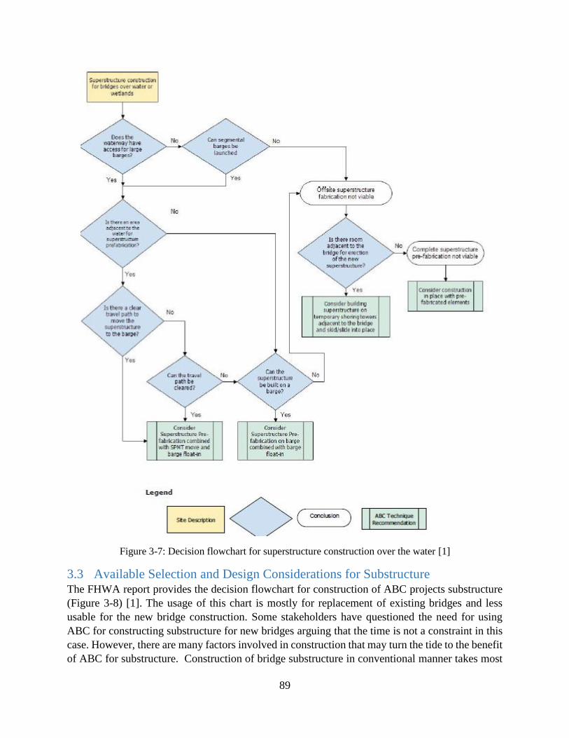
89
Figure 3-7: Decision flowchart for superstructure construction over the water [1]
3.3 Available Selection and Design Considerations for Substructure The FHWA report provides the decision flowchart for construction of ABC projects substructure
(Figure 3-8) [1]. The usage of this chart is mostly for replacement of existing bridges and less
usable for the new bridge construction. Some stakeholders have questioned the need for using
ABC for constructing substructure for new bridges arguing that the time is not a constraint in this
case. However, there are many factors involved in construction that may turn the tide to the benefit
of ABC for substructure. Construction of bridge substructure in conventional manner takes most
90
of the bridge construction time. To reduce construction time, the use of prefabricated elements and
modular systems are beneficial and very effective. The prefabricated elements and modular
systems are normally built in the shop or near the site and assembled at the site. In addition to time
saving, this provides for better quality, safety, and control on project schedule and cost. The
substructure can be placed over deep or shallow foundation according to the soil and site conditions
[47]. This study attempts to provide guidelines for selection of substructure for ABC projects not
only for the case of replacement of existing bridges, but also for construction of new bridges.
Similar considerations may result in viable options for the use of ABC foundations.
The use of modular abutment that can accommodate a joint-free and maintenance-free substructure
element is preferable when targeting to reduce the construction time. The modular abutment can
be designed and constructed integrally or semi-integrally with the superstructure. In that point, the
use of integral abutment is preferable for providing joint-free riding surface at abutment and full
moment connection between substructure elements that can emulate the cast-in-place construction
[47]. Another factor should be considered in the construction of substructure over the water is the
water activity. Water activity timing and navigation restrictions may affect the design, construction
method, and selection of type of the substructure.

91
Figure 3-8: Decision flowchart for substructure construction [1]
3.3.1 Selection of Substructure Elements and Systems
The type of substructure elements and systems depends on; a) parameters affecting selection of
ABC methods and elements in general as described in Figure 3-4, b) compatibility of substructure
with superstructure and foundation, and c) parameters specific to the substructure (Figure 3-9).

92
Figure 3-9: Bridge substructure element selection parameters
3.3.2 Parameters affecting the selection of bridge elements and construction methods in general
As discussed in the previous section related to selection of construction methods and superstructure
element and system type, a set of general parameters discussed on Figure 2 influence the selection
process with accessibility and availability of space having the major impact. Apparently, these
parameters will affect in the same way the selection of substructure as well. For example, if there
is no accessibility to transport large systems to the site, individual elements installed by
conventional crane have to be used also for the substructure, the same way as for the superstructure.
Therefore, for the substructure, the type of elements and methods selected for superstructure
should be followed in general. Accordingly, there is no need to repeat the selection process for
substructure as far as general parameters are concerned. In the same manner, this also applies to
the construction method to be used for substructure, and the size of elements or subsystems.
Beyond these preliminary decisions that will follow those of the superstructure, following
describes the specifics on substructure in accordance with compatibility with superstructure and
foundation, as well as parameters specific to substructure.
Compatibility of Substructure with Superstructure and Bridge Configuration
In addition to geometric compatibility, the bridge elements and units are expected to be compatible
in design and construction with each other. For instance, the performance anticipated for
connection between super- and substructure may favor or limit the use of one or another type of
substructure. For fully-integral, semi-integral, or siding connection with the superstructure, the
abutment or pier cap shall accommodate the transfer of moment and shear as per design and
therefore these conditions will become defining parameters for the type of the pier or abutment.
Compatibility of Substructure with Foundation
Substructure is a component of the bridge that connects superstructure and substructure together
and transfer loads from superstructure to foundation. Therefore, the compatibility of substructure
with superstructure as well as foundation in design and construction is necessary for integrity and
unity of bridge. For instance, the seismic condition of soil may constrain the use of some types of
connections between foundation and substructure, causing limitation in selection of substructure
element, design, and construction type.
General Parameters
Bridge Substructure Elements Selection
Design Constraints and Considerations
Site Condition &Accessibility
Environmental considerations
Risk and Cost
Time Constraint
Compatibility with superstructure
Compatibility with foundation
Substructure specific parameters
Impact by Debris
Exposure to Water/Salt/Splash
Impact of Vehiclesand vessels
93
3.3.3 Parameters Specific to Substructure
There are some factors that may only affect the selection of substructure. One of them is exposure
of substructure to water, salt, or splash. In this case, special considerations should be considered
to select the materials and elements of the bridge substructure that provide for more durability in
the related harsh and corrosive environment. Additionally, in some cases the bridge substructure
may be impacted by vehicles for the case of bridge over roadway, or in the case of bridge across
waterways by debris and vessels. This may result in the use of protective elements around the
piers or the use of pier wall in the substructure.
3.3.4 Selection of Substructure based on Compatibility with Superstructure and Substructure-
specific Parameters
In this section, a flowchart for selection of substructure for ABC projects is developed based on
the superstructure system and ABC method considering interrelations and other parameters
involved. Similar to the selection of ABC method flowcharts, the substructure selection can be
divided into three flowcharts based on the construction of a bridge over roads (Figure 3-4), over
railroads (Figure 3-5), and over wetlands (Figure 3-6). By use of these flowcharts, it is possible to
define the ABC method and subsequently identify the superstructure systems. It should be noted
that the use of prefabricated elements is viable for all types of ABC methods. Nevertheless,
prioritization for the use of ABC method should be applied based on all factors involved in
selection process including but not limited to cost, safety, quality, and onsite construction time.
Consequently, the substructure system can be selected according to the ABC method and the
parameters listed in the previous section. A flowchart that can be used to select the substructure
types and components is shown in Figure 3-10a. As shown in this flowchart, the substructure
includes pier and abutment system, buried bridges and modular culverts. The flowchart is divided
to its main segments, and for clarity the segments are presented in Figures 3-10b through 3-1-e.
The flowchart in Fig. 3-10b will lead to the type of substructure system based on span length and
other constraints. As the type of substructure is selected, the substructure elements and systems
can be selected using Figs. 3-10c to 3-10e for pier and abutment system, buried bridges, and
culverts, respectively.
When using pier and abutment system, to select the pier elements, it should be considered if piers
are affected by the errant vehicle or there is a possibility to collect derbies between piers when the
bridge passes over the wetland. In these cases, the wall piers should be used instead of piers. In
other cases, the piers and pier columns can be used. In this case, the integration of pier cap or pier
wall cap with the superstructure should be considered to determine the connection and
accommodation require to join the pier cap and superstructure. Also, this should be considered that
cap may be placed directly over the pile or it may be placed over the pier column. Consequently,
the pier column should be supported by footing. As shown in Figure 3-10c, abutment system
includes wing wall and abutment wall. Wing wall can be constructed using precast elements or as
a modular unit. In abutment wall, the integrity of abutment with the superstructure is important.
When the integration of abutment with superstructure is vital, the use of fully or semi-integral
abutment is needed. When the integrity of abutment with superstructure is not important, the
cantilever, spill-through, or stub abutment can be used. It should be noted that the use of fully
94
integral abutment that is constructed with the superstructure is preferable due to its full moment
connection with the superstructure as well as increasing the speed of construction.
The type of buried bridges can be narrowed down based on availability, environmental effects and
span as shown in Fig. 3-10d. Similar process can be applied for selection of culvert elements from
Fig. 3-10-e.
3.3.5 Suitability of Substructure Types with Respect to Foundation
In this section, considering interrelations and other parameters involved, a flowchart for selection
of substructure for ABC projects is developed based on the foundation system and the ABC
method. As shown in Figure 3-10, the selection of substructure for new bridges can be based on
whether the bridge foundation is deep or shallow. The selection of deep or shallow foundation can
be based on the site conditions, existence of river, soil conditions, etc., which are discussed in the
next sections. However, in this section, a flowchart that can be used to select the substructure types
and components based on the foundation is presented (Figure 3-11).
When a deep foundation such as pile foundation is used for the bridge, it may also serve as a bridge
pier and connect directly to pier cap (also serve as pile cap). In this case, the bridge does not need
a separate pier. When the deep foundation cannot be used as a pier, a pile cap is needed. Pile cap
function as it relates to connection to substructure would be like a shallow foundation. Therefore,
a pier column or pier wall is required in order to transfer superstructure loads to the foundation.
The type of substructure elements will have to satisfy the flowchart presented earlier in Figure 3-
10. After selecting the pier wall or pier column, the type of pier cap can be determined by
considering the compatibility with the superstructure and connectivity design between substructure
and superstructure.
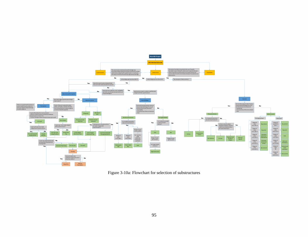
95
Figure 3-10a: Flowchart for selection of substructures
New ABC Project
ABC Method Selected
Superstructure Substructure
-Is pier affected by the errant vehicles? -Is there a need to prevent collection of debries between piers in rivers? Or,- Is there a design or other reason to have a pier wall?
-Is abutment or a portion of it to be made integral with superstructure?
Pier wall
Concrete Filled Tubes
Simple PierCap
Fully Integral Abutment/ Cap
Culverts
No
Yes
NoYes
Abument system
Pier system
Is pier cap to be made integral with superstructure?
Is pier cap supported directly by deep pile extended from finish grade?
Pier Column
Yes
Yes
No
Cantiliver/stub/spill-through abutment
Precast concrete contiliver
Modular precast wing wall
Abutment wall
Wing wall
Semi Integral Abutment/ CapPier wall Cap with
integrity detailSimple
wall pier
Is pier wall cap to be made integral with superstructure?
Yes No
Footing
Deep PileShallow
foundation
Pier Cap with integrity detail
No
Pier Column
Pier wall
Foundation
If part of the pier exposed to water splash, salt water, variation of water level, the protective measures against corrosion should be applied
If there is a potential for vehicle or vessel impact to pier, protective measures against impact damage should be applied
Does the superstructure design dictatethe use of pier and/or abutment system?
Is the bridge span less than 20 ft?
Yes
YesNo
Buried Bridges
No
RectangularBox
Three-Sided Box
Arch
Reinforced Concrete Corrugated Metal
Arch
High Profile Arch
Box
Range of span
8 ft to 48 ft
Range of span
8 ft to 48 ft
Range of span15 ft to 102 ft
Range of span20 ft to 82 ft
Range of span20 ft to 53 ft
For low rise, wide
waterwayenclosures,
aesthetic
For larger height clearance
Is it needed to provide a natural stream bottom? No
Yes
Circular
Is it needed to provide a natural stream bottom?
Pipe Arch and Elliptical Shapes
Arches
Box Sections
No
Yes No
Multiple Barrels
3-sided frame culvert
Precast Concrete
Is there a need to obtain adequate hydraulic capacity under low embankments or for wide waterways?
Metal Culverts
Is it needed to provide a natural stream bottom?
NoYes
Yes
Corrugated Steel Aluminum
Range of sizes
12 to 144 inRound Arch
Range of sizes
15 to 120 inPipe Arch
Range of sizes
5 ft to 20 ft
Structural plate steel
underpasses
Range of sizes
6 ft to 25 ft
Structural plate steel
arches
Range of sizes
9 ft to 20 ftBox Culverts
Range of span 60 to
156 inRound Arch
Range of span
6 ft to 21 ftPipe Arch
Range of span
5 ft to 28 ftArch
Range of span
12 ft to 20 ft
Vehicular Underpass
Range of span6ft
Pedestrian/animal
underpass
Range of span
8 ft to 25 ft Box Culverts
Is the bridge span less than 100 ft?
Yes
No
Does the site conditions, cost, availability, and other considerations warrant the use of buried bridges?
YesNo Substructure in part or whole is prefbricated
integral with the superstructure
The construction method selected for bridge may prescribe prefabrication/construction of portion or all the substructure integral with superstructure. In such case, the steps to follow will need to be adjusted accordingly.
Site and soil condition may lead to the use of sepcific foundation type limiting the substructure types and designs. Other flowcharts are presented in this report that can be used to determine the interrelation between foundation and substructure..
The structure is likely a culvert.
Abument and Pier System
Does soil and/or site condition require the use of deep fouindation?
NoYes
Does the bridge superstructure design require piers?
Yes No
Do the following and other facrtors necessitate/advantage the use of reinforced concrete elements? - Availability- Corrosiveness of the environment- Cost
Yes No
Do the following and other facrtors necessitate/advantage the use of reinforced concrete elements? - Availability- Corrosiveness of the environment- Cost
Yes No

96
Figure 3-11b: Flowchart for selection of substructure system
New ABC
ABC Method Selected
Superstructure Substructure Foundation
Does the superstructure design dictatethe use of pier and/or abutment system?
Is the bridge span less than 20 ft?
Yes
YesNo
Buried Bridges
No Is the bridge span less than 100
Yes
No
Does the site conditions, cost, availability, and other considerations warrant the use of buried bridges?
Yes
No
Substructure in part or whole is prefbricated integral with the superstructure
The construction method selected for bridge may prescribe prefabrication/construction of portion or all the substructure integral with superstructure. In such case, the steps to follow will need to be adjusted accordingly.
Site and soil condition may lead to the use of sepcific foundation type limiting the substructure types and designs. Other flowcharts are presented in this report that can be used to determine the interrelation between foundation and substructure..
The structure is likely a culvert.
Abument and Pier SystemCulverts
Continue on Abutment-Pier System Section
Continue on Buried Bridges Section
Continue on CulvertsSection

97
Figure 3-12c: Flowchart for selection of substructure elements for pier and abutment system
-Is pier affected by the errant vehicles? -Is there a need to prevent collection of debries between piers in rivers? Or,- Is there a design or other reason to have a pier wall?
-Is abutment or a portion of it to be made integral with superstructure?
Pier wall
Concrete Filled Tubes
Simple PierCap
Fully Integral Abutment/ Cap
No
Yes
No
Yes
Abument system
Pier system
Is pier cap to be made integral with superstructure?
Is pier cap supported directly by deep pile extended from finish grade?
Pier Column
Yes
Yes
No
Cantiliver/stub/spill-through abutment
Precast concrete contiliver
Modular precast wing wall
Abutment wall
Wing wall
Semi Integral Abutment/ CapPier wall Cap with
integrity detailSimple wall
pier cap
Is pier wall cap to be made integral with superstructure?
Yes No
Footing
Deep PileShallow
foundation
Pier Cap with integrity detail
No
Pier Column
Pier wall
If part of the pier exposed to water splash, salt water, variation of water level, the protective measures against corrosion should be applied
If there is a potential for vehicle or vessel impact to pier, protective measures against impact damage should be applied
Abument and Pier System
Does soil and/or site condition require the use of deep fouindation?
NoYes
Does the bridge superstructure design require piers?
Yes No

98
Figure 3-13c: Flowchart for selection of substructure elements for buried bridges
Buried Bridges
RectangularBox
Three-Sided Box
Arch
Reinforced Concrete Corrugated Metal
Arch
High Profile Arch
Box
Range of span
8 ft to 48 ft
Range of span
8 ft to 48 ft
Range of span15 ft to 102 ft
Range of span
Range of span20 ft to 53 ft
For low rise, wide
waterwayenclosures,
aesthetic
For larger height
clearance
Is it needed to provide a natural stream bottom? No
Yes
Is it needed to provide a natural stream bottom?
NoYes
Do the following and other facrtors necessitate/advantage the use of reinforced concrete elements? - Availability- Corrosiveness of the
Yes No
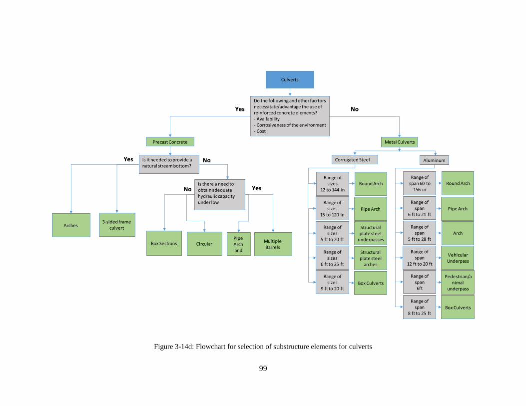
99
Figure 3-14d: Flowchart for selection of substructure elements for culverts
Culverts
Circular
Is it needed to provide a natural stream bottom?
Pipe Arch and
Arches
Box Sections
No
Yes No
Multiple Barrels
3-sided frame culvert
Precast Concrete
Is there a need to obtain adequate hydraulic capacity under low
Metal Culverts
Yes
Corrugated Steel Aluminum
Range of sizes
12 to 144 inRound Arch
Range of sizes
15 to 120 inPipe Arch
Range of sizes
5 ft to 20 ft
Structural plate steel
underpasses
Range of sizes
6 ft to 25 ft
Structural plate steel
arches
Range of sizes
9 ft to 20 ftBox Culverts
Range of span 60 to
156 inRound Arch
Range of span
6 ft to 21 ftPipe Arch
Range of span
5 ft to 28 ftArch
Range of span
12 ft to 20 ft
Vehicular Underpass
Range of span6ft
Pedestrian/animal
underpass
Range of span
8 ft to 25 ft Box Culverts
Do the following and other facrtors necessitate/advantage the use of reinforced concrete elements? - Availability- Corrosiveness of the environment- Cost
Yes No
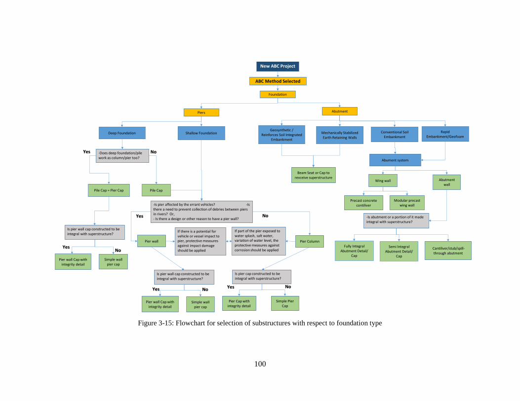
100
Figure 3-15: Flowchart for selection of substructures with respect to foundation type
New ABC Project
ABC Method Selected
Piers
Deep Foundation Shallow Foundation
-Does deep foundation/pile work as column/pier too?
Pile Cap = Pier Cap Pile Cap
-Is pier affected by the errant vehicles? -Is there a need to prevent collection of debries between piers in rivers? Or,- Is there a design or other reason to have a pier wall?
Pier wall
Simple PierCap
NoYes
Is pier cap constructed to be integral with superstructure?
Yes
Pier wall Cap with integrity detail
Simple wall pier cap
Is pier wall cap constructed to be integral with superstructure?
Yes No
Pier Cap with integrity detail
No
Pier Column
Pier wall Cap with integrity detail
Simple wall pier cap
Is pier wall cap constructed to be integral with superstructure?
YesNo
Geosynthetic / Reinforces Soil Integrated
Embankment
Mechanically Stabilized Earth Retaining Walls
Rapid Embankment/Geofoam
Foundation
Abutment
Beam Seat or Cap to revceive superstructure
If there is a potential for vehicle or vessel impact to pier, protective measuresagainst impact damage should be applied
If part of the pier exposed to water splash, salt water, variation of water level, the protective measures against corrosion should be applied
Conventional Soil Embankment
-Is abutment or a portion of it made integral with superstructure?
Fully Integral Abutment Detail/
Cap
Abument system
Cantiliver/stub/spill-through abutment
Precast concrete contiliver
Modular precast wing wall
Abutment wall
Wing wall
Semi Integral Abutment Detail/
Cap
NoYes
101
3.4 Selection and Design Considerations for Foundation OU TO PROVIDE THEIR WORK FOR THIS SECTION
3.5 Design considerations for Connections Design and type of joints and connections between the bridge elements and modular systems
influence the ABC speed and integrity. The type of connection can affect live load distribution,
seismic performance, rideability, and durability of the bridge. In addition, connection type plays a
prominent role to achieve a desirable structural performance and bridge construction time. The
designer needs to develop the bridge structure type and ABC method according to the site and time
restrictions. In this case, the connections between modular elements, superstructure and
substructure, and superstructure elements play an essential role to drive a desirable performance
and construction timing. Connections can define how easily the modular units and bridge elements
connect and assemble together as well as emulating the cast-in-place construction. Therefore, the
construction time of connections depends on curing time of the closure pour, type of connection,
and number of connections [47].
In superstructure, to improve joint performance, post-tensioning technique can help to close
shrinkage cracks in the joints, prevent cracking and improve load transfer between connected
elements. Post-tensioning technique can be used in female-female shear key joints or match cast
with epoxy joints. Post-tensioning technique can also be used with closure pour [47]. The
following are the considerations for superstructure connections:
-Providing full moment connection, shear transfer, or free rotation or sliding resulted from design
and practical consideration
-Providing a durable connection equal to or surpassing precast deck
-Suitability of connection for heavy truck traffic
-Provide quality for riding surface
-Eliminating the need for overlays despite overlays increasing the construction tolerance
-Eliminating the need for post-tensioning in the field if possible
-Providing for fast setting and rapid strength gain
By considering the above factors for the superstructure connection construction, the use of Ultra-
High-Performance Concrete (UHPC) in the modular and other prefabricated superstructure
element connection as a closure pour is highly recommended. This concrete can provide a highly
durable and rapid construction. Due to its high strength, a small width connection is enough to
connect modular units and members. However, the bridge owner may hesitate using the UHPC
due to its high cost, proprietary nature, and other restrictions.
In the connection between superstructure and substructure, sometimes the use of full moment
connections to emulate the cast-in-place connections is preferable. In this case, closure pour

102
connection should be used that provides high quality, rapid construction, and better riding surface.
If self-compacting concrete is used as closure pour, it can provide high homogeneity, uniformity
and no need for vibration [47].
3.6 Categorization of Bridges based on Bridge Span ABC aims to reduce the onsite construction time and activity. To that point, the use of modular
systems in the bridge construction is preferable. Typically bridge designers categorize bride super-
and substructures into 4 groups based on the bridge span as follow [47].
40 ft. < bridge span< 70 ft.
70 ft. < bridge span< 100 ft.
100 ft. < bridge span< 130 ft.
bridge span> 130 ft.
In a particular ABC project, the bridge span or girder spacing is normally selected based on the
fabrication and shipping considerations, and vice-versa. For bridge span up to 130 ft., pre-
tensioning method (without the need for post-tensioning) can be used in the site. If girders or
superstructure modules are shipped to the site, and bridge span over 130 ft., post-tensioning
technique needs to be used to extend the bridge span. However, it may be economical to add more
piers to reduce the dead load in each pier, and to reduce the shipping weight of the bridge
components. Also, it should be noted that facilitating the bridge construction with the use of lifting
and crane-based fabrication has been reported normally to be the most cost-effective method [47].
However, this assessment may be valid if the time and speed of construction are not prohibiting
factors. When prefabricated modular systems and bridge elements are fabricated near the site, it is
possible to increase the girder spans over 130 ft.
3.7 Considerations for superstructure system and elements selection There are different viable systems available to be considered as superstructure for the ABC
projects. However, each system has its own advantages and disadvantages. Therefore, a
superstructure system should be selected in such a way to meet the project goals, provide higher
safety, and be constructed in minimum time. Also, a value analysis is needed to select the best
economic system [31, 54]. The factors that should be considered in the selection of each
superstructure system is summarized in Table 3-2 provides alternatives for superstructure element
types and related considerations.
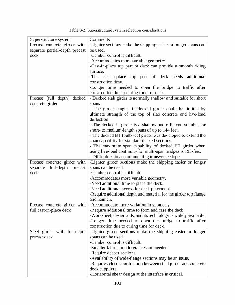
103
Table 3-2: Superstructure system selection considerations
Superstructure system Comments
Precast concrete girder with
separate partial-depth precast
deck
-Lighter sections make the shipping easier or longer spans can
be used.
-Camber control is difficult.
-Accommodates more variable geometry.
-Cast-in-place top part of deck can provide a smooth riding
surface.
-The cast-in-place top part of deck needs additional
construction time.
-Longer time needed to open the bridge to traffic after
construction due to curing time for deck.
Precast (full depth) decked
concrete girder
- Decked slab girder is normally shallow and suitable for short
spans
- The girder lengths in decked girder could be limited by
ultimate strength of the top of slab concrete and live-load
deflection
- The decked U-girder is a shallow and efficient, suitable for
short- to medium-length spans of up to 144 feet.
- The decked BT (bulb-tee) girder was developed to extend the
span capability for standard decked sections.
- The maximum span capability of decked BT girder when
using live-load continuity for multi-span bridges is 195-feet.
- Difficulties in accommodating transverse slope.
Precast concrete girder with
separate full-depth precast
deck
-Lighter girder sections make the shipping easier or longer
spans can be used.
-Camber control is difficult.
-Accommodates more variable geometry.
-Need additional time to place the deck.
-Need additional access for deck placement.
-Require additional depth and material for the girder top flange
and haunch.
Precast concrete girder with
full cast-in-place deck
-Accommodate more variation in geometry
-Require additional time to form and case the deck
-Worksheet, design aids, and its technology is widely available.
-Longer time needed to open the bridge to traffic after
construction due to curing time for deck.
Steel girder with full-depth
precast deck
-Lighter girder sections make the shipping easier or longer
spans can be used.
-Camber control is difficult.
-Smaller fabrication tolerances are needed.
-Require deeper sections.
-Availability of wide-flange sections may be an issue.
-Requires close coordination between steel girder and concrete
deck suppliers.
-Horizontal shear design at the interface is critical.
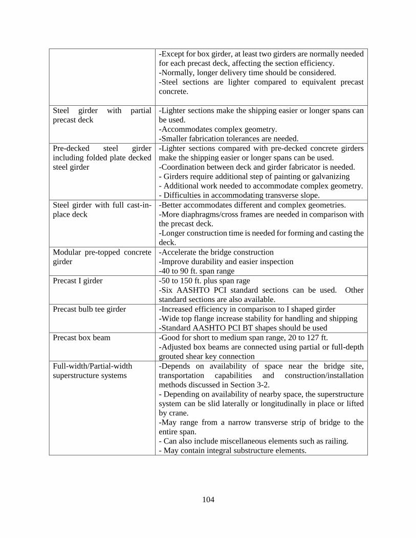
104
-Except for box girder, at least two girders are normally needed
for each precast deck, affecting the section efficiency.
-Normally, longer delivery time should be considered.
-Steel sections are lighter compared to equivalent precast
concrete.
Steel girder with partial
precast deck
-Lighter sections make the shipping easier or longer spans can
be used.
-Accommodates complex geometry.
-Smaller fabrication tolerances are needed.
Pre-decked steel girder
including folded plate decked
steel girder
-Lighter sections compared with pre-decked concrete girders
make the shipping easier or longer spans can be used.
-Coordination between deck and girder fabricator is needed.
- Girders require additional step of painting or galvanizing
- Additional work needed to accommodate complex geometry.
- Difficulties in accommodating transverse slope.
Steel girder with full cast-in-
place deck
-Better accommodates different and complex geometries.
-More diaphragms/cross frames are needed in comparison with
the precast deck.
-Longer construction time is needed for forming and casting the
deck.
Modular pre-topped concrete
girder
-Accelerate the bridge construction
-Improve durability and easier inspection
-40 to 90 ft. span range
Precast I girder -50 to 150 ft. plus span rage
-Six AASHTO PCI standard sections can be used. Other
standard sections are also available.
Precast bulb tee girder -Increased efficiency in comparison to I shaped girder
-Wide top flange increase stability for handling and shipping
-Standard AASHTO PCI BT shapes should be used
Precast box beam -Good for short to medium span range, 20 to 127 ft.
-Adjusted box beams are connected using partial or full-depth
grouted shear key connection
Full-width/Partial-width
superstructure systems
-Depends on availability of space near the bridge site,
transportation capabilities and construction/installation
methods discussed in Section 3-2.
- Depending on availability of nearby space, the superstructure
system can be slid laterally or longitudinally in place or lifted
by crane.
-May range from a narrow transverse strip of bridge to the
entire span.
- Can also include miscellaneous elements such as railing.
- May contain integral substructure elements.
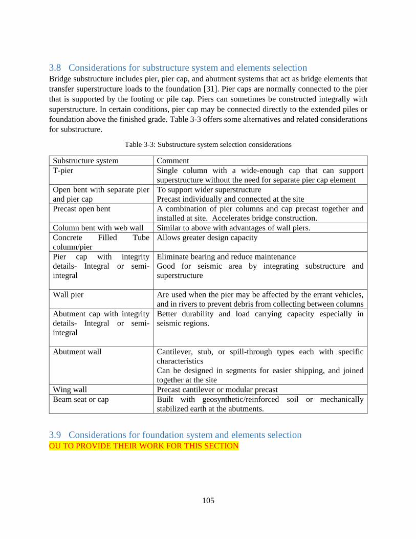
105
3.8 Considerations for substructure system and elements selection Bridge substructure includes pier, pier cap, and abutment systems that act as bridge elements that
transfer superstructure loads to the foundation [31]. Pier caps are normally connected to the pier
that is supported by the footing or pile cap. Piers can sometimes be constructed integrally with
superstructure. In certain conditions, pier cap may be connected directly to the extended piles or
foundation above the finished grade. Table 3-3 offers some alternatives and related considerations
for substructure.
Table 3-3: Substructure system selection considerations
Substructure system Comment
T-pier
Single column with a wide-enough cap that can support
superstructure without the need for separate pier cap element
Open bent with separate pier
and pier cap
To support wider superstructure
Precast individually and connected at the site
Precast open bent A combination of pier columns and cap precast together and
installed at site. Accelerates bridge construction.
Column bent with web wall Similar to above with advantages of wall piers.
Concrete Filled Tube
column/pier
Allows greater design capacity
Pier cap with integrity
details- Integral or semi-
integral
Eliminate bearing and reduce maintenance
Good for seismic area by integrating substructure and
superstructure
Wall pier Are used when the pier may be affected by the errant vehicles,
and in rivers to prevent debris from collecting between columns
Abutment cap with integrity
details- Integral or semi-
integral
Better durability and load carrying capacity especially in
seismic regions.
Abutment wall Cantilever, stub, or spill-through types each with specific
characteristics
Can be designed in segments for easier shipping, and joined
together at the site
Wing wall Precast cantilever or modular precast
Beam seat or cap Built with geosynthetic/reinforced soil or mechanically
stabilized earth at the abutments.
3.9 Considerations for foundation system and elements selection OU TO PROVIDE THEIR WORK FOR THIS SECTION
106
4 Existing Bridge Replacement According to the National Bridge Inventory data for bridges in the US in 2016, 9% of the bridges
were in poor condition, 15% had service life older than average design life of the bridge, and 9%
of them needed urgent strengthening or rehabilitation [55]. These data is indicative of the necessity
of bridge maintenance, construction, and rehabilitation. One common method in improving the
bridge performance is demolishing the existing bridge and construction of a new bridge. However,
this method is expensive and is not a favorable option in urban areas where there is high
congestion. New bridge construction can cause significant mobility and traffic problems. To
address this issue, other options become more attractive that include retrofitting or strengthening
of existing bridges, reuse, or partial replacement of existing bridges. To select the proper method
to improve the life and performance of an existing bridge, a precise and comprehensive evaluation
of existing bridges is needed. The bridge evaluation may well discover that some parts or
subsystems of the bridge, such as foundation and/or substructure, are in good condition and only
replacement of superstructure is necessary. The benefit of foundation and substructure reuse is the
time and cost saving especially in urban and populated areas.
To accelerate the bridge construction, the reuse of substructures, let it be with some repair or
modification, is favorable. In this case, the existing substructure must be inspected thoroughly and
the best method to reuse the existing substructures is determined. The assessment of the existing
foundation is a multidisciplinary task that needs geotechnical, construction, structural, and
hydraulic expertise. The purpose of substructures assessment therefore is to provide enough
information for decision making on the reuse of substructure.
An FHWA workshop in 2013 laid the foundation for evaluation means and methods for reuse of
substructure and foundation for bridge replacement [2]. Figure 4-1 is an example guide for
evaluation of the condition of substructure and foundation reported by this workshop [56].
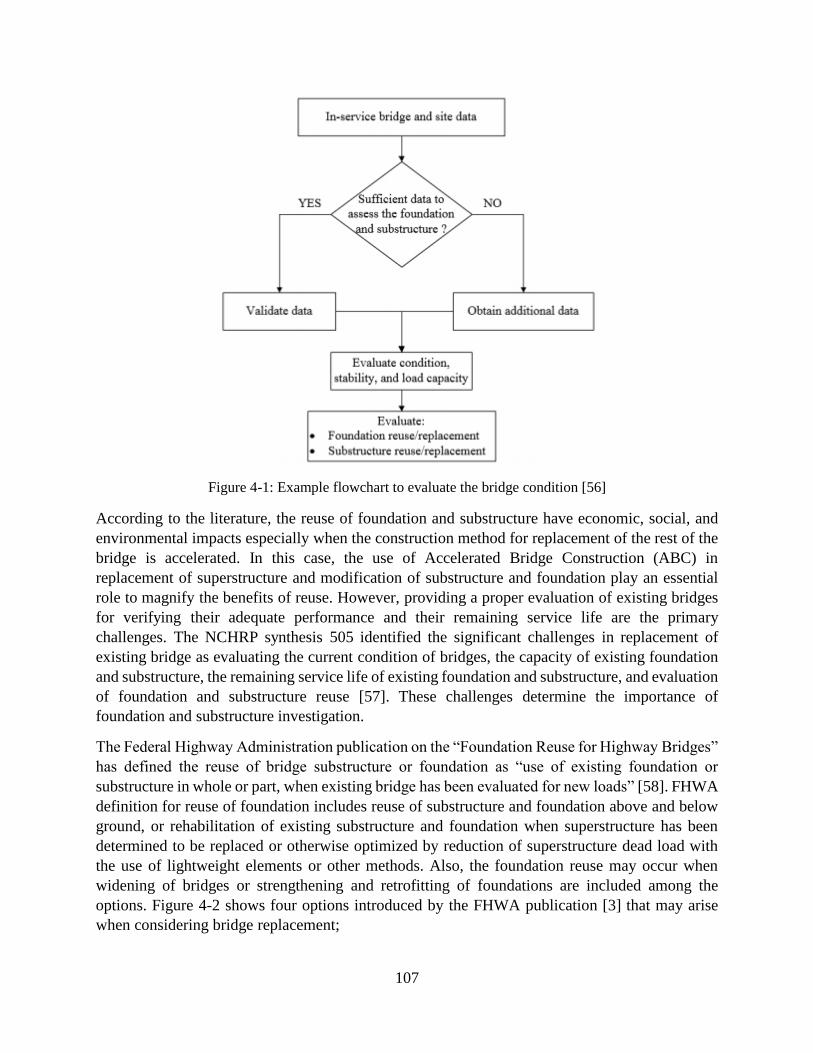
107
Figure 4-1: Example flowchart to evaluate the bridge condition [56]
According to the literature, the reuse of foundation and substructure have economic, social, and
environmental impacts especially when the construction method for replacement of the rest of the
bridge is accelerated. In this case, the use of Accelerated Bridge Construction (ABC) in
replacement of superstructure and modification of substructure and foundation play an essential
role to magnify the benefits of reuse. However, providing a proper evaluation of existing bridges
for verifying their adequate performance and their remaining service life are the primary
challenges. The NCHRP synthesis 505 identified the significant challenges in replacement of
existing bridge as evaluating the current condition of bridges, the capacity of existing foundation
and substructure, the remaining service life of existing foundation and substructure, and evaluation
of foundation and substructure reuse [57]. These challenges determine the importance of
foundation and substructure investigation.
The Federal Highway Administration publication on the “Foundation Reuse for Highway Bridges”
has defined the reuse of bridge substructure or foundation as “use of existing foundation or
substructure in whole or part, when existing bridge has been evaluated for new loads” [58]. FHWA
definition for reuse of foundation includes reuse of substructure and foundation above and below
ground, or rehabilitation of existing substructure and foundation when superstructure has been
determined to be replaced or otherwise optimized by reduction of superstructure dead load with
the use of lightweight elements or other methods. Also, the foundation reuse may occur when
widening of bridges or strengthening and retrofitting of foundations are included among the
options. Figure 4-2 shows four options introduced by the FHWA publication [3] that may arise
when considering bridge replacement;
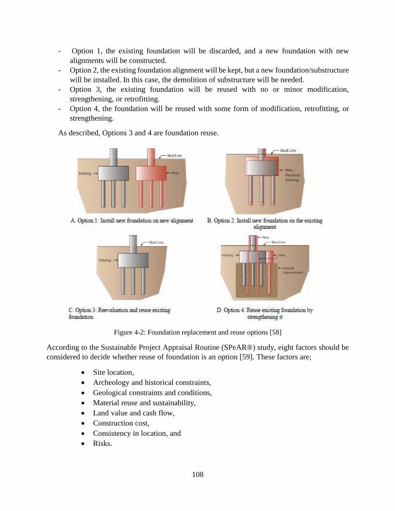
108
- Option 1, the existing foundation will be discarded, and a new foundation with new
alignments will be constructed.
- Option 2, the existing foundation alignment will be kept, but a new foundation/substructure
will be installed. In this case, the demolition of substructure will be needed.
- Option 3, the existing foundation will be reused with no or minor modification,
strengthening, or retrofitting.
- Option 4, the foundation will be reused with some form of modification, retrofitting, or
strengthening.
As described, Options 3 and 4 are foundation reuse.
Figure 4-2: Foundation replacement and reuse options [58]
According to the Sustainable Project Appraisal Routine (SPeAR®) study, eight factors should be
considered to decide whether reuse of foundation is an option [59]. These factors are;
Site location,
Archeology and historical constraints,
Geological constraints and conditions,
Material reuse and sustainability,
Land value and cash flow,
Construction cost,
Consistency in location, and
Risks.
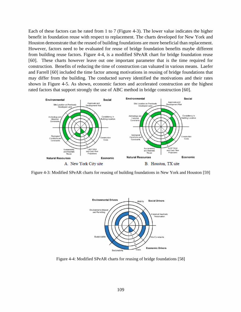
109
Each of these factors can be rated from 1 to 7 (Figure 4-3). The lower value indicates the higher
benefit in foundation reuse with respect to replacement. The charts developed for New York and
Houston demonstrate that the reused of building foundations are more beneficial than replacement.
However, factors need to be evaluated for reuse of bridge foundation benefits maybe different
from building reuse factors. Figure 4-4, is a modified SPeAR chart for bridge foundation reuse
[60]. These charts however leave out one important parameter that is the time required for
construction. Benefits of reducing the time of construction can valuated in various means. Laefer
and Farrell [60] included the time factor among motivations in reusing of bridge foundations that
may differ from the building. The conducted survey identified the motivations and their rates
shown in Figure 4-5. As shown, economic factors and accelerated construction are the highest
rated factors that support strongly the use of ABC method in bridge construction [60].
Figure 4-3: Modified SPeAR charts for reusing of building foundations in New York and Houston [59]
Figure 4-4: Modified SPeAR charts for reusing of bridge foundations [58]

110
Figure 4-5: Motivations for bridge foundation reuse [58]
4.1 Type and Design of Existing Foundations OU TO PROVIDE THEIR WORK FOR THIS SECTION
4.2 Evaluation of Existing Substructure for Potential Reuse The critical issue in the reuse of bridge substructure and foundation is defining the remaining
service life (durability) of the bridge components. Accordingly, to find if the reusing of bridge
components are economical, one needs to perform a life-cycle cost analysis based on the remaining
service life of the bridge elements. Therefore, an exhaustive bridge evaluation should be
conducted to first determine the remaining service life of bridge components. The substructure
components of bridges are wall piers, columns, abutments, wing walls, and pier caps. These
elements can be constructed from reinforced concrete or steel.
During its service life, steel can be corroded if not protected properly. This corrosion can cause
reduction in the cross-section of steel and consequently decrease the strength of steel elements. In
the reinforced concrete elements, the reinforcements can be corroded or/and the concrete cover
may be degraded. The corrosion of reinforcements and degradation of concrete cover are normally
interrelated. For example, the concrete cover may initially cracks due to the loads, causing the
penetration of corrosive agents into the concrete, and leading to corrosion of reinforcements, that
in turn because of volume increase will damage the concrete cover further.
The durability and remaining service life assessment of bridge components is categorized in three
stages as shown in Figure 4-6.

111
Figure 4-6: Durability and residual service life assessment of bridge substructure [58]
In the preliminary assessment, the previous performance issues, environmental conditions, and
concerns related to the durability of a bridge are investigated. This assessment is playing an
essential role in providing an appropriate plan for further inspections and tests as well as repair
type and extent. The preliminary assessment and procedure are summarized in Table 4-1.
Table 4-1: Preliminary assessment procedure [58]
As shown in Table 4-1, a comprehensive review of previous records and a visual inspection is
required in the preliminary assessment. Then, a plan is developed for further investigation through
inspection and testing to provide the information required for determining the condition of bridges.
Finally, a life-cycle cost analysis needs to evaluate the benefit of reusing of foundation and
substructure.
According to the preliminary evaluation by considering observations and inspections, local
experiences and conditions, and environmental conditions, a test plan can be developed to define
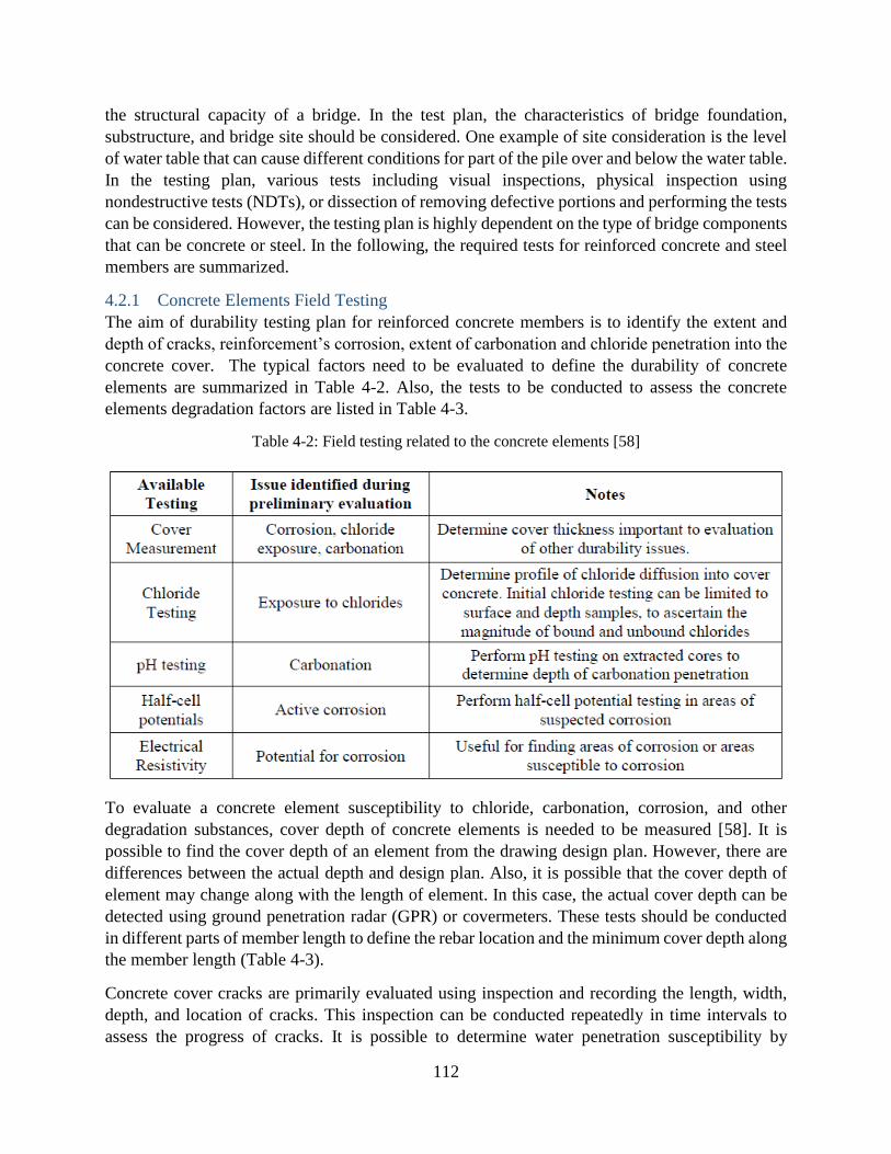
112
the structural capacity of a bridge. In the test plan, the characteristics of bridge foundation,
substructure, and bridge site should be considered. One example of site consideration is the level
of water table that can cause different conditions for part of the pile over and below the water table.
In the testing plan, various tests including visual inspections, physical inspection using
nondestructive tests (NDTs), or dissection of removing defective portions and performing the tests
can be considered. However, the testing plan is highly dependent on the type of bridge components
that can be concrete or steel. In the following, the required tests for reinforced concrete and steel
members are summarized.
4.2.1 Concrete Elements Field Testing
The aim of durability testing plan for reinforced concrete members is to identify the extent and
depth of cracks, reinforcement’s corrosion, extent of carbonation and chloride penetration into the
concrete cover. The typical factors need to be evaluated to define the durability of concrete
elements are summarized in Table 4-2. Also, the tests to be conducted to assess the concrete
elements degradation factors are listed in Table 4-3.
Table 4-2: Field testing related to the concrete elements [58]
To evaluate a concrete element susceptibility to chloride, carbonation, corrosion, and other
degradation substances, cover depth of concrete elements is needed to be measured [58]. It is
possible to find the cover depth of an element from the drawing design plan. However, there are
differences between the actual depth and design plan. Also, it is possible that the cover depth of
element may change along with the length of element. In this case, the actual cover depth can be
detected using ground penetration radar (GPR) or covermeters. These tests should be conducted
in different parts of member length to define the rebar location and the minimum cover depth along
the member length (Table 4-3).
Concrete cover cracks are primarily evaluated using inspection and recording the length, width,
depth, and location of cracks. This inspection can be conducted repeatedly in time intervals to
assess the progress of cracks. It is possible to determine water penetration susceptibility by
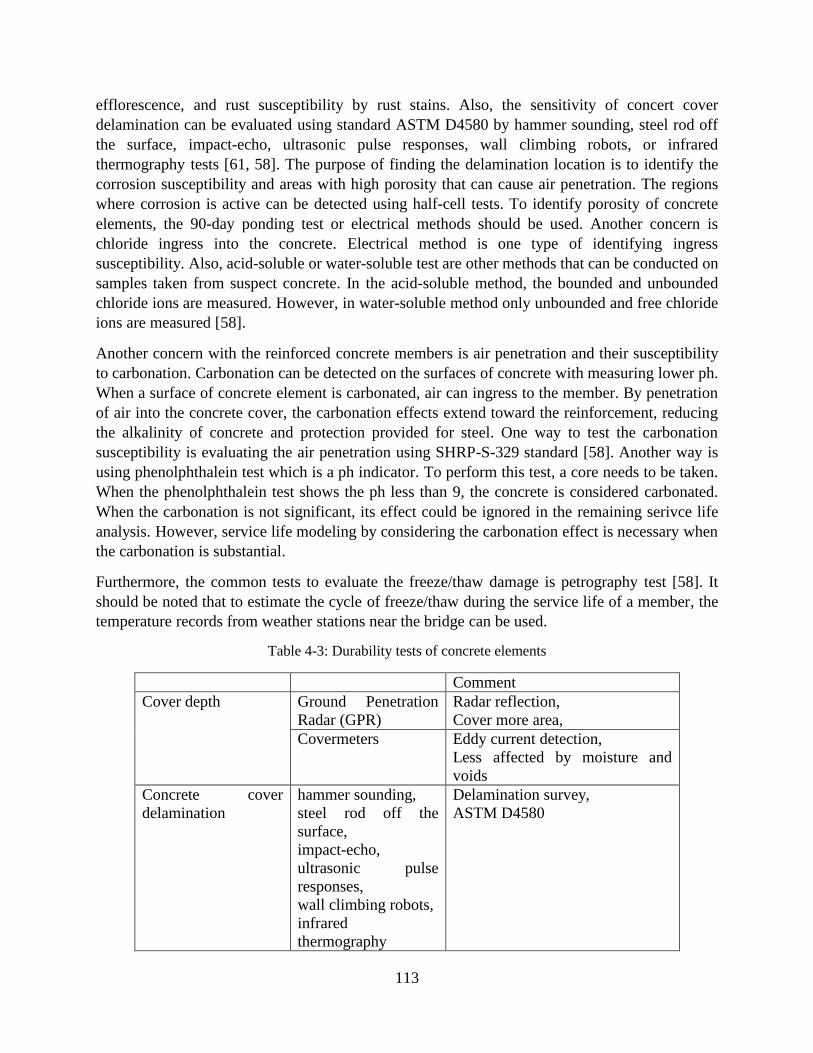
113
efflorescence, and rust susceptibility by rust stains. Also, the sensitivity of concert cover
delamination can be evaluated using standard ASTM D4580 by hammer sounding, steel rod off
the surface, impact-echo, ultrasonic pulse responses, wall climbing robots, or infrared
thermography tests [61, 58]. The purpose of finding the delamination location is to identify the
corrosion susceptibility and areas with high porosity that can cause air penetration. The regions
where corrosion is active can be detected using half-cell tests. To identify porosity of concrete
elements, the 90-day ponding test or electrical methods should be used. Another concern is
chloride ingress into the concrete. Electrical method is one type of identifying ingress
susceptibility. Also, acid-soluble or water-soluble test are other methods that can be conducted on
samples taken from suspect concrete. In the acid-soluble method, the bounded and unbounded
chloride ions are measured. However, in water-soluble method only unbounded and free chloride
ions are measured [58].
Another concern with the reinforced concrete members is air penetration and their susceptibility
to carbonation. Carbonation can be detected on the surfaces of concrete with measuring lower ph.
When a surface of concrete element is carbonated, air can ingress to the member. By penetration
of air into the concrete cover, the carbonation effects extend toward the reinforcement, reducing
the alkalinity of concrete and protection provided for steel. One way to test the carbonation
susceptibility is evaluating the air penetration using SHRP-S-329 standard [58]. Another way is
using phenolphthalein test which is a ph indicator. To perform this test, a core needs to be taken.
When the phenolphthalein test shows the ph less than 9, the concrete is considered carbonated.
When the carbonation is not significant, its effect could be ignored in the remaining serivce life
analysis. However, service life modeling by considering the carbonation effect is necessary when
the carbonation is substantial.
Furthermore, the common tests to evaluate the freeze/thaw damage is petrography test [58]. It
should be noted that to estimate the cycle of freeze/thaw during the service life of a member, the
temperature records from weather stations near the bridge can be used.
Table 4-3: Durability tests of concrete elements
Comment
Cover depth Ground Penetration
Radar (GPR)
Radar reflection,
Cover more area,
Covermeters Eddy current detection,
Less affected by moisture and
voids
Concrete cover
delamination
hammer sounding,
steel rod off the
surface,
impact-echo,
ultrasonic pulse
responses,
wall climbing robots,
infrared
thermography
Delamination survey,
ASTM D4580
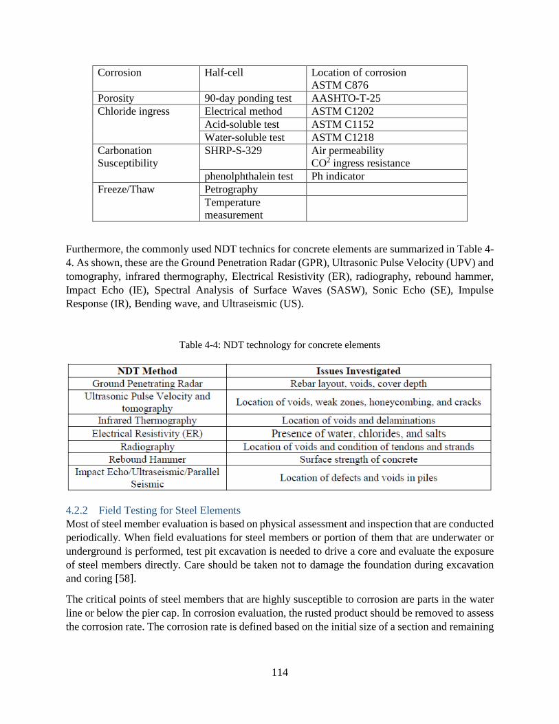
114
Corrosion Half-cell Location of corrosion
ASTM C876
Porosity 90-day ponding test AASHTO-T-25
Chloride ingress Electrical method ASTM C1202
Acid-soluble test ASTM C1152
Water-soluble test ASTM C1218
Carbonation
Susceptibility
SHRP-S-329 Air permeability
CO2 ingress resistance
phenolphthalein test Ph indicator
Freeze/Thaw Petrography
Temperature
measurement
Furthermore, the commonly used NDT technics for concrete elements are summarized in Table 4-
4. As shown, these are the Ground Penetration Radar (GPR), Ultrasonic Pulse Velocity (UPV) and
tomography, infrared thermography, Electrical Resistivity (ER), radiography, rebound hammer,
Impact Echo (IE), Spectral Analysis of Surface Waves (SASW), Sonic Echo (SE), Impulse
Response (IR), Bending wave, and Ultraseismic (US).
Table 4-4: NDT technology for concrete elements
4.2.2 Field Testing for Steel Elements
Most of steel member evaluation is based on physical assessment and inspection that are conducted
periodically. When field evaluations for steel members or portion of them that are underwater or
underground is performed, test pit excavation is needed to drive a core and evaluate the exposure
of steel members directly. Care should be taken not to damage the foundation during excavation
and coring [58].
The critical points of steel members that are highly susceptible to corrosion are parts in the water
line or below the pier cap. In corrosion evaluation, the rusted product should be removed to assess
the corrosion rate. The corrosion rate is defined based on the initial size of a section and remaining
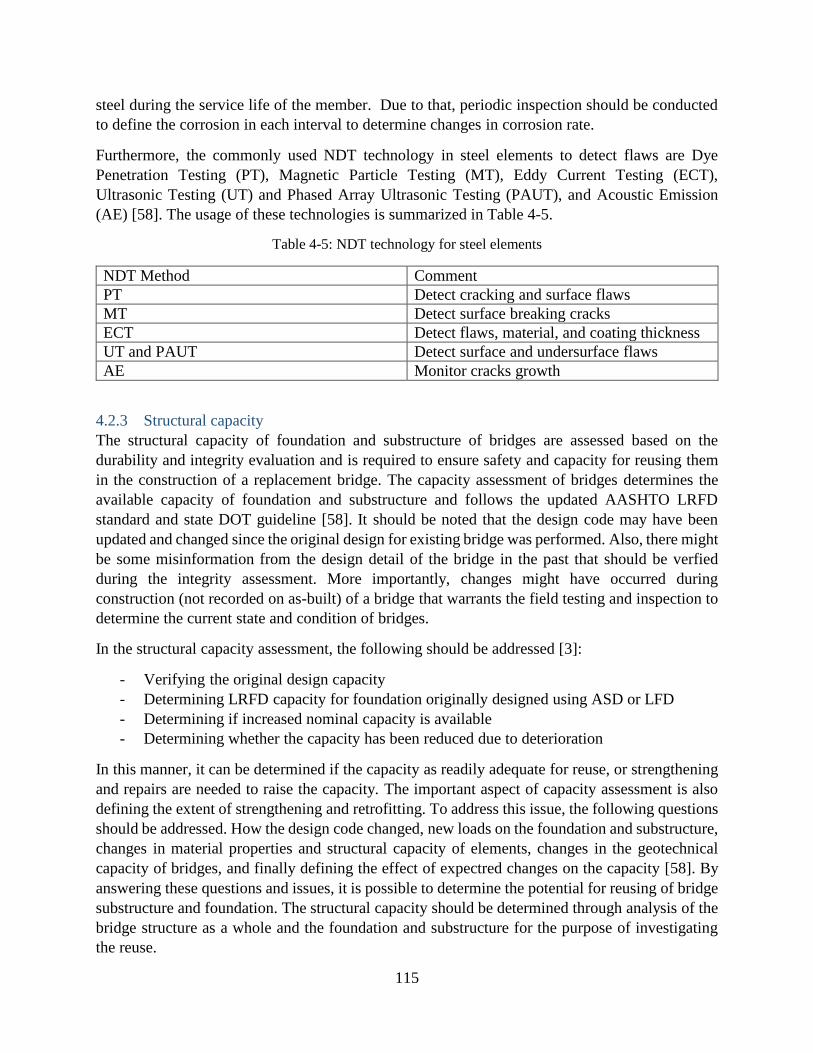
115
steel during the service life of the member. Due to that, periodic inspection should be conducted
to define the corrosion in each interval to determine changes in corrosion rate.
Furthermore, the commonly used NDT technology in steel elements to detect flaws are Dye
Penetration Testing (PT), Magnetic Particle Testing (MT), Eddy Current Testing (ECT),
Ultrasonic Testing (UT) and Phased Array Ultrasonic Testing (PAUT), and Acoustic Emission
(AE) [58]. The usage of these technologies is summarized in Table 4-5.
Table 4-5: NDT technology for steel elements
NDT Method Comment
PT Detect cracking and surface flaws
MT Detect surface breaking cracks
ECT Detect flaws, material, and coating thickness
UT and PAUT Detect surface and undersurface flaws
AE Monitor cracks growth
4.2.3 Structural capacity
The structural capacity of foundation and substructure of bridges are assessed based on the
durability and integrity evaluation and is required to ensure safety and capacity for reusing them
in the construction of a replacement bridge. The capacity assessment of bridges determines the
available capacity of foundation and substructure and follows the updated AASHTO LRFD
standard and state DOT guideline [58]. It should be noted that the design code may have been
updated and changed since the original design for existing bridge was performed. Also, there might
be some misinformation from the design detail of the bridge in the past that should be verfied
during the integrity assessment. More importantly, changes might have occurred during
construction (not recorded on as-built) of a bridge that warrants the field testing and inspection to
determine the current state and condition of bridges.
In the structural capacity assessment, the following should be addressed [3]:
- Verifying the original design capacity
- Determining LRFD capacity for foundation originally designed using ASD or LFD
- Determining if increased nominal capacity is available
- Determining whether the capacity has been reduced due to deterioration
In this manner, it can be determined if the capacity as readily adequate for reuse, or strengthening
and repairs are needed to raise the capacity. The important aspect of capacity assessment is also
defining the extent of strengthening and retrofitting. To address this issue, the following questions
should be addressed. How the design code changed, new loads on the foundation and substructure,
changes in material properties and structural capacity of elements, changes in the geotechnical
capacity of bridges, and finally defining the effect of expectred changes on the capacity [58]. By
answering these questions and issues, it is possible to determine the potential for reusing of bridge
substructure and foundation. The structural capacity should be determined through analysis of the
bridge structure as a whole and the foundation and substructure for the purpose of investigating
the reuse.

116
An important aspect of performing analysis and capacity assessment is defining the future loads
on bridges. The future loading of bridges may change or stay the same. The changes in live and
dead loads of bridges can occur due to a widening of a bridge, the use of a new superstructure, the
potential of extreme hazards, or use of new materials. The summary of possible changes in the
bridge loads is listed in Table 4-6.
In the modeling and analysis of bridge to evaluate the potential for reusing the existing bridge
components, the structural capacity of the bridge elements should be assessed. The pier column,
wall piers, pier cap, and abutments are the elements in the substructure of bridges, and their
capacity and functionality should be evaluated for their reuse.
In addition to vertical loading, a critical loading for the pier column and pier wall is the lateral
loading that creates moments in the element. According to the AASHTO design specification, the
lateral loading can be induced from a seismic event, vessel or traffic collision, ice or debris, wind,
or construction consequences [62]. Thermal variation can also generate lateral loading on
substructure. These loads can make tensile stress in the elements and create cracks in the portion
of elements that are in tension. Another reason for cracks could be corrosion of rebar in the
elements. According to the Service Limit states of AASHTO standard specification section 5.4.2.6,
in the capacity evaluation, the emphasis should be to prevent the occurrence of tensile stress instead
of providing for a higher modulus of rupture [62]. In Strength Limit states evaluation for extreme
event limit case, the rupture modulus should be used when there are no significant cracks in the
tensile portion of the elements. Other loads due to the construction like traffic rerouting, bridge
sliding, demolition, ground movement, and construction equipment loads also need to be
considered.

117
Table 4-6: Possible changes in the loading of a bridge for potential reusing [58]
Abutment and wingwall can experience settlement, horizontal movement, rotation, and slope
stability problem. The excessive movement of walls can make the wall unable to support the soil
and surcharge loads at rest condition of the wall. When the wall moves, the wall is in an active
state that causes a reduction in the lateral pressure coefficient. This reduction causes reduction in
pressure loads to the wall. However, to reach the active state of a wall, a minimum amount of wall
movement is necessary. The required amount of movements are specified in section C3.11.1-1 of
AASHTO standard specifications [62]. Conversely, by movement of walls, the soil in front of wall
is in the passive state. In passive state, the coefficient of earth pressure increases compared to the
at rest state and prevents movement of the wall. Since in the active state of the wall the coefficient
of earth pressure decrease, a safety factor higher than 1.5 should be considered. When the wall is
in the at rest state, a safety factor of 1.35 should be used. It should be noted that to define the state
of a wall, a proper estimation of wall movement is needed to determine actual pressure to the wall.
Pier caps generally experience shear and flexural demands. The transverse and longitudinal
reinforcement of these elements should be evaluated prior to performing capacity analysis due to
their essential function in the element capacity. The transverse (shear) rebar are more prone to
corrosion because they are closer to the face of the elements. To perform capacity analysis, the
strut and tie analysis should be conducted according to the section 5.6.3 of AASHTO LRFD design
specification [62]. Flexural and shear reinforcements simulate as ties in the strain and concrete
simulate as struts.
4.2.3.1 Modeling and Analysis
Different approaches of modeling and numerical simulation is used to determine the forces,
moment, and stresses that a bridge structure experience, including determination of loads that the
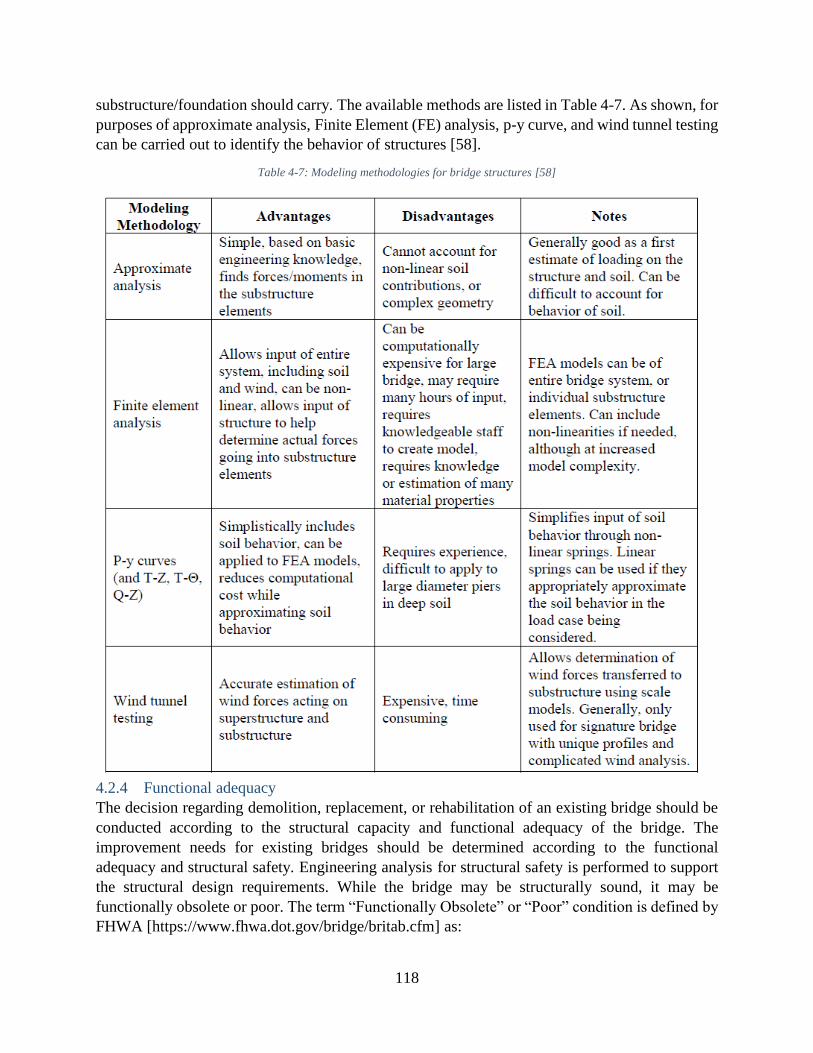
118
substructure/foundation should carry. The available methods are listed in Table 4-7. As shown, for
purposes of approximate analysis, Finite Element (FE) analysis, p-y curve, and wind tunnel testing
can be carried out to identify the behavior of structures [58].
Table 4-7: Modeling methodologies for bridge structures [58]
4.2.4 Functional adequacy
The decision regarding demolition, replacement, or rehabilitation of an existing bridge should be
conducted according to the structural capacity and functional adequacy of the bridge. The
improvement needs for existing bridges should be determined according to the functional
adequacy and structural safety. Engineering analysis for structural safety is performed to support
the structural design requirements. While the bridge may be structurally sound, it may be
functionally obsolete or poor. The term “Functionally Obsolete” or “Poor” condition is defined by
FHWA [https://www.fhwa.dot.gov/bridge/britab.cfm] as:

119
This term was previously defined in https://www.fhwa.dot.gov/bridge/0650dsup.cfm as having an
appraisal rating of 3 or less for Item 68 (Deck Geometry), Item 69 (Underclearances), or Item 72
(Approach Roadway Alignment), OR having an appraisal rating of 3 for Item 67 (Structural Condition)
or Item 71 (Waterway Adequacy). Functionally obsolete is a legacy classification that was used to
implement the Highway Bridge Program, which was discontinued with the enactment of MAP-21. As
such, we encourage the use of the Good-Fair-Poor bridge condition measures outlined in the Pavement
and Bridge Condition Performance Measures final rule, published in January of 2017.
In such cases (i.e., functionally obsolete or poor), improvements and modifications may be
required to upgrade the bridge functionality including elevating or widening by considering current
and future needs. Factors to be considered for bridge functionality includes roadway width, clear
height (over and under-clearance), and waterway adequacy.
FHWA has provided other guidelines to determine bridge dimension and geometry, functional
description, and evaluating bridges conditions [63]. State DOTs have their own guidelines for
evaluation of bridge conditions. As an example, Florida DOT provides its structural design
guideline and the requirements for bridge widths and geometry. An example is shown in Table 4-
8.
Table 4-8: Minimum width for existing bridges [64]
4.2.5 Integrity and remaining service life
The geotechnical and structural stability and integrity check for bridge components are required to
assess for potential reuse. The assessment and evaluation can be conducted using visual
inspections, testing on the samples, performing NDT tests, and taking cores from the existing
components and conditions. The main issue in the integrity of a bridge is deterioration of
components due to their exposing to the environment during their service life. This issue can cause
decrease in the capacity of components.

120
The bridge components were generally designed based on the day the bridge was constructed using
the predicted conditions and loads through the Load and Resistance Factor Design (LRFD)
standard method or the applicable code at the time of design. Also, in the construction of bridges,
proper QA/QC may not have been applied. Additionally, changes in design code might have
occurred compared to the time when bridge was originally designed. In fact, in redesigning the
existing bridge, the confidence in initial construction and design quality in addition to the current
condition should be considered. Therefore, a comprehensive and precise integrity evaluation of
bridge is essential with the use of the material properties, deterioration effect in the capacity of
components, damages occurred to the components, and changes in the soil system and stability.
To address these factors, all members of the bridge should be evaluated along with the geotechnical
issues [58]. Figure 4-7 illustrates the required integrity assessment steps for components of bridges
constructed from concrete or steel [58]. The integrity assessment of steel and concrete components
are reviewed in this section.
Figure 4-7: Aspects of Integrity assessment [58]
4.2.5.1 Integrity of concrete elements
The reinforced concrete is commonly used in the construction of pier wall, abutment wall, column,
pier cap, piles, and shafts. Since concrete can bear very low tensile strength, the reinforcing bars
are used in the concrete elements to increase the tensile strength of the elements. Concrete can
provide compressive strength and cover for rebar to prevent corrosion. Cracks in concrete can
expose the rebar and cause corrosion. In fact, the rebar corrosion is the main control factor for the
service life of the concrete elements. This factor was discussed in the evaluation of service life of
reinforced concrete. Another aspect of concrete elements is integrity evaluation. Concrete elements

121
integrity assessment is summarized in Table 4-9 and includes, initial design, construction defects,
degradation, damage, and cracking of concrete elements.
In the initial design assessment, the mix properties, reinforcement layout, compressive strength,
and reinforcement strength are evaluated. Mix properties of concrete elements include
water/cement ratio, aggregate classifications and properties, entrained air in the concrete, etc. To
assess the compressive strength of concrete elements, generally, the unconfined compressive tests
should be conducted. However, the NDT technology can be used to verify the properties, detect
defects or ensure the integrity of the concrete element. In reinforcement layout assessment, the
size of rebar, lap splice length, and all the aspects of reinforcement placement are evaluated using
ground penetration radar (GPR), radiography, or covermeter test. The reinforcement strength can
also be determined using design drawing details and tests on the samples taken from the members.
Defects and issues left during construction may include honeycombing, forming of weak zones,
cold joints, and voids in concrete elements. In honeycombing, the improper mixing of aggregate
with cement due to insufficient or poorly sized aggregates causes lower strength in member and
formation of paste bonding. Weak zones are also initiated due to improper mixing of aggregates
and higher w/c ration that leads to lower compressive strength. In large elements like pier caps,
the pouring of concrete may be performed in several steps that normally results in cold joints and
discontinuities plane between sections. The other problem is in formation of voids around rebar
due to insufficient fluidity of concrete resulting in decrease in capacity of members.
The concrete degradation and damage that affects long-term concrete quality and durability
include freeze-thaw damage, alkali-silica reactivity (ASR), delayed ettringite formation (DEF),
external sulfate attack, paste erosion, calcium leaching, and fire damage [58]. In freeze-thaw
damage, the trapped water due to improper mix design freeze and expand. The existence of high
level of ASR can cause durability and integrity problems for concrete elements. This damage can
be detected using photographic analysis in the form of gel formed in concrete. DEF which is due
to poor construction technique can cause expansion and cracks in concrete. This issue also can be
detected by photography. The dissolved sulfate in water can damage the submerged concrete
elements. Paste erosion is another damage that occurs in the exterior face of elements and cause
declares in load caring capacity of elements. Calcium leaching is due to infiltration of water into
cracks and causes loss of paste inside the element. Fire also can damage the concrete elements by
creating large cracks and buckling of rebar. This damage can be detected by evaluating the rebar
layout using covermeter or GPR method.
Cracking that is one of important factors in the integrity assessment of bridges can be caused by
shrinkage, change in temperature, flexural and shear forces, ASR, DEF, foundation movement,
seismic effects, and corrosion [58]. Cracking due to shrinkage, ASR, DEF, and freeze-thaw are
representative of problems in mix design of concrete. Structural cracks due to flexural and shear
loads forms in tensile areas. Substantial structural cracks are representative of elements overload.
Foundation movement can also cause tensile stress in concrete element and cracking. Seismic
loads can also cause cracks. Corrosion of rebar accompanies increase in volume of rust product
and creates cracks in concrete cover.
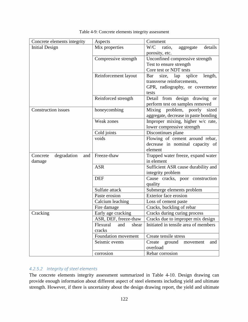
122
Table 4-9: Concrete elements integrity assessment
Concrete elements integrity Aspects Comment
Initial Design Mix properties W/C ratio, aggregate details
porosity, etc.
Compressive strength Unconfined compressive strength
Test to ensure strength
Core test or NDT tests
Reinforcement layout Bar size, lap splice length,
transverse reinforcements,
GPR, radiography, or covermeter
tests
Reinforced strength Detail from design drawing or
perform test on samples removed
Construction issues honeycombing Mixing problem, poorly sized
aggregate, decrease in paste bonding
Weak zones Improper mixing, higher w/c rate,
lower compressive strength
Cold joints Discontinues plane
voids Flowing of cement around rebar,
decrease in nominal capacity of
element
Concrete degradation and
damage
Freeze-thaw Trapped water freeze, expand water
in element
ASR Sufficient ASR cause durability and
integrity problem
DEF Cause cracks, poor construction
quality
Sulfate attack Submerge elements problem
Paste erosion Exterior face erosion
Calcium leaching Loss of cement paste
Fire damage Cracks, buckling of rebar
Cracking Early age cracking Cracks during curing process
ASR, DEF, freeze-thaw Cracks due to improper mix design
Flexural and shear
cracks
Initiated in tensile area of members
Foundation movement Create tensile stress
Seismic events Create ground movement and
overload
corrosion Rebar corrosion
4.2.5.2 Integrity of steel elements
The concrete elements integrity assessment summarized in Table 4-10. Design drawing can
provide enough information about different aspect of steel elements including yield and ultimate
strength. However, if there is uncertainty about the design drawing report, the yield and ultimate
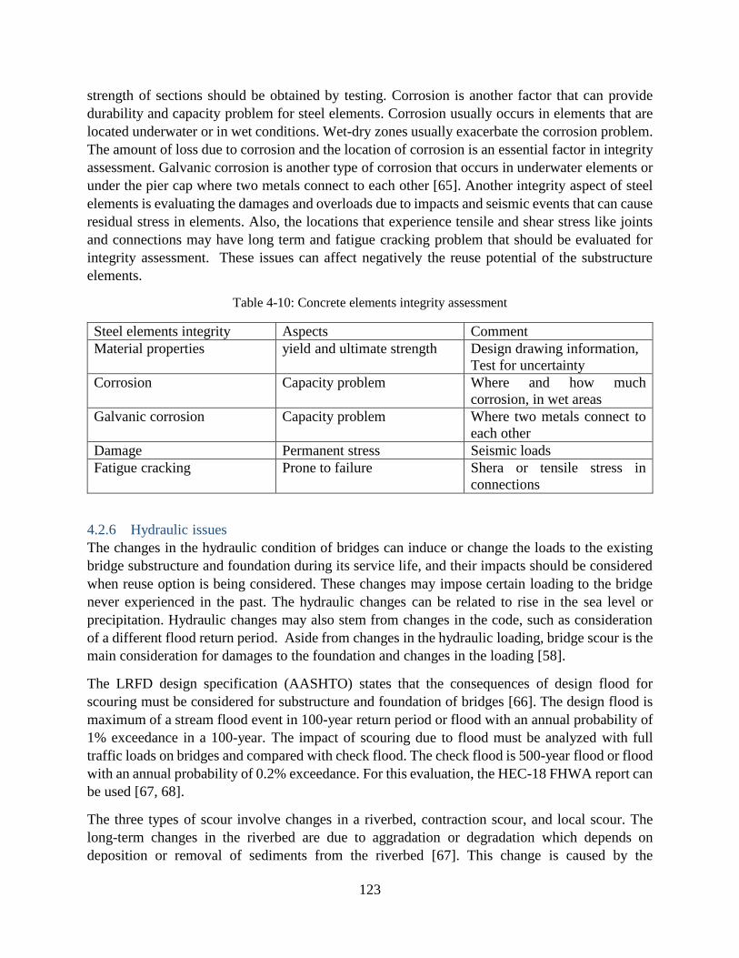
123
strength of sections should be obtained by testing. Corrosion is another factor that can provide
durability and capacity problem for steel elements. Corrosion usually occurs in elements that are
located underwater or in wet conditions. Wet-dry zones usually exacerbate the corrosion problem.
The amount of loss due to corrosion and the location of corrosion is an essential factor in integrity
assessment. Galvanic corrosion is another type of corrosion that occurs in underwater elements or
under the pier cap where two metals connect to each other [65]. Another integrity aspect of steel
elements is evaluating the damages and overloads due to impacts and seismic events that can cause
residual stress in elements. Also, the locations that experience tensile and shear stress like joints
and connections may have long term and fatigue cracking problem that should be evaluated for
integrity assessment. These issues can affect negatively the reuse potential of the substructure
elements.
Table 4-10: Concrete elements integrity assessment
Steel elements integrity Aspects Comment
Material properties yield and ultimate strength Design drawing information,
Test for uncertainty
Corrosion Capacity problem Where and how much
corrosion, in wet areas
Galvanic corrosion Capacity problem Where two metals connect to
each other
Damage Permanent stress Seismic loads
Fatigue cracking Prone to failure Shera or tensile stress in
connections
4.2.6 Hydraulic issues
The changes in the hydraulic condition of bridges can induce or change the loads to the existing
bridge substructure and foundation during its service life, and their impacts should be considered
when reuse option is being considered. These changes may impose certain loading to the bridge
never experienced in the past. The hydraulic changes can be related to rise in the sea level or
precipitation. Hydraulic changes may also stem from changes in the code, such as consideration
of a different flood return period. Aside from changes in the hydraulic loading, bridge scour is the
main consideration for damages to the foundation and changes in the loading [58].
The LRFD design specification (AASHTO) states that the consequences of design flood for
scouring must be considered for substructure and foundation of bridges [66]. The design flood is
maximum of a stream flood event in 100-year return period or flood with an annual probability of
1% exceedance in a 100-year. The impact of scouring due to flood must be analyzed with full
traffic loads on bridges and compared with check flood. The check flood is 500-year flood or flood
with an annual probability of 0.2% exceedance. For this evaluation, the HEC-18 FHWA report can
be used [67, 68].
The three types of scour involve changes in a riverbed, contraction scour, and local scour. The
long-term changes in the riverbed are due to aggradation or degradation which depends on
deposition or removal of sediments from the riverbed [67]. This change is caused by the
124
hydrological condition of the river and not related to the bridge. Contraction scour occurs when
the water velocity increases due to decrease in the channel width. The local scour occur near
foundation where the stream causes vortices. The vortices occur when the regular stream is
obstructed. This obstruction creates a high-velocity stream that can run the sediment [58].
4.2.7 Seismic considerations
The seismic evaluation of a bridge structure is conducted using C/D (capacity/demands) ratio.
When this ratio is over or equal to 1, it shows that the element and structure have sufficient seismic
capacity to resists seismic displacement and force [58]. The demands consist of displacement
demand and force/moment demand. The displacement demand is evaluated using pushover
analysis by considering the nonlinear behavior of materials and elements to define the ductility of
bridges and elements. The force/moment demand estimates the actual forces and loading that the
bridges and elements experience.
In a seismic event, the bridge element should be allowed to deform to absorb energy and prevent
collapse. Allowing the plastic hinges to develop in a member controls the level of load applied to
the structure. To evaluate this nonlinear behavior of elements, the pushover analysis is normally
performed [58].
In the case of reusing the bridge components, the maximum considered event (MCE) should be
used to define the maximum damage to the bridge. There are different methods to perform seismic
demand analysis which depends on the bridge detail, magnitude of a seismic event, and importance
of bridge. The detail of demand and seismic capacity evaluation of bridges can be found in the
AASHTO standard specifications for LRFD seismic bridge design [66].
4.2.8 Other Considerations
Other consideration and hazards that should be considered in evaluation of existing bridges for
potential reusing include wind loads, impacts loads, fire damages, ice and debris flow, and blasts.
These potential hazards need to be considered depending on the condition and location of the
bridge.
Wind load generally impact the superstructure and pier and cause lateral and moment loads in the
foundation of bridges. Wind loads have two levels of operational and extreme impact. In operation
impact level, the wind speed is considered to be 55 mph and impacts to the bridge with regular
traffic. In an extreme level, the speed of wind depends on the location of bridge. Also, the change
in climate should be considered during the time that the bridge designed and the time that it is
evaluated for potential reuse. The climate change may make changes in maximum wind speed and
return period. The required evaluation to assess wind impact to the bridge can be conducted using
AASTO specification provision through LRFD standard specification [62].
The effect of impacts from vehicles and marine vessels collision on the bridge foundation and
substructure has been considered in new design code. For this analysis, the performance-based
analysis can be used to evaluate the truck collision impact on the piers [69]. In the case of marine
vessel collision impacts, the AASHTO LRFD standard specification can be used to assess the
vessel collision impact on bridge columns and foundation [62].
125
Burning underneath a bridge overpass can have adverse effects on the bridge component strength.
The burning may cause weakness of steel rebar in the concrete elements. This weakening can
produce cracks in the elements. To evaluate the effect of burning on the bridge components and
identify the repair methods, the NCHRP report 12-85 can be implemented [70].
In case of considering the effect of ice and debris flow impact on the bridge piers and abutments
that can produce lateral loads to the foundation, The NCHRP 445 can be used [71]. Also, to
perform an analysis to assess the capacity of members due to the debris impact, the standard
AASHTO specification can be used [62].
The loading due to the potential blasts and explosion are new and need to be evaluated. To evaluate
the blasts effects and induced loads to bridges, the bridge design security manual provided by
FHWA can be used [72]. Also, NCHRP report 645 provides a guideline to perform an analysis
and identify the blast hazard into the bridges [73].
4.2.9 Remaining Service Life Analysis
Current condition and “State” of the substructure and foundation can be evaluated using the
durability and integrity assessment as described above. Next step is to determine how the condition
will be changed during the anticipated service life. This determination is critical in life-cycle-cost
analysis and decision making on reuse, repair or replacement strategies for substructure and
foundation. There have been several models developed to predict deterioration of construction
material and geotechnical formation. More detailed discussion is included later in the section titled
“Life-Cycle-Cost Analysis.”
4.3 Evaluation of existing foundation for potential reuse
4.3.1 Structural capacity
NDE Field Testing Modeling and Analysis
4.3.2 Functional adequacy (width, height, traffic, etc.)
4.3.3 Integrity and remaining service life
4.3.4 Hydraulic issues
4.3.5 Seismic considerations
OU TO PROVIDE THEIR WORK FOR THESE SECTIONS
4.4 Suitability of Substructure Types with Respect To Superstructure and Bridge
Configuration Suitability can be defined as having the structural load bearing capacity and at the same being
compatible. Compatibility refers to geometric and design consistency. For example, for the
substructure to be suitable for receiving the superstructure, it has to have adequate structural load
bearing capacity to transfer the loads from superstructure to the foundation. At the same time, the
substructure must be able to accommodate the superstructure geometry by width, height and

126
alignment. For example, the width of superstructure, at the minimum by its bearing footprint, shall
be enveloped by the substructure. Furthermore, the substructure design and detailing shall
accommodate as designed connection to superstructure. For example, if the superstructure design
prescribes an integral abutment or pier connection, the substructure shall be able to provide for the
establishment of such connection in its detail. If any suitability requirements is not satisfied by
the current condition of the substructure, modifications, rehabilitation, and/or retrofitting shall be
performed on the substructure to make it suitable for superstructure. Another way to provide for
suitability is to revise the design of the superstructure to be able to make it suitable for the existing
substructure (e.g., use lighter deck elements). The decision on which of the two approaches are
chosen to provide for suitability should be made with economical (time-cost) and structural
considerations.
Flowchart in Figure 4-8 shows the process with which the substructure suitability can be checked
against the superstructure.
Figure 4-8: Factors effecting in the selection of existing bridge components
4.5 Suitability of Foundation Types with Respect To Superstructure/Substructure
and Bridge Configuration
OU TO PROVIDE THEIR WORK FOR THIS SECTION
Suitability of Bridge Substructure To Receive Superstructure
Adequate Capacity
Geometric Compatibility
Design/DetailsCompatibiity
Adequate Width Adequate Height Exact Alignment
Protect against adverse effects to
prevent
Design and Implement strengthening to increase
substructure capacity
Yes Yes
No
No
And/Or
Revise superstructure design to reduce the
demandon substructure
Extend/Modify the substructure to
accommodate alignment
Increase height to accommodate superstructure
Extend/Modify the substructure to
accommodate alignment
No
No YesYes
Modify substructure to accommodate the
superstructure detail
No
Yes
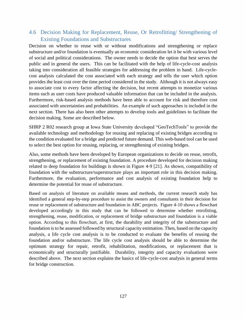
127
4.6 Decision Making for Replacement, Reuse, Or Retrofitting/ Strengthening of
Existing Foundations and Substructures Decision on whether to reuse with or without modifications and strengthening or replace
substructure and/or foundation is eventually an economic consideration let it be with various level
of social and political considerations. The owner needs to decide the option that best serves the
public and in general the users. This can be facilitated with the help of life-cycle-cost analysis
taking into consideration all feasible strategies for addressing the problem in hand. Life-cycle-
cost analysis calculated the cost associated with each strategy and tells the user which option
provides the least cost over the time period considered in the study. Although it is not always easy
to associate cost to every factor affecting the decision, but recent attempts to monetize various
items such as user costs have produced valuable information that can be included in the analysis.
Furthermore, risk-based analysis methods have been able to account for risk and therefore cost
associated with uncertainties and probabilities. An example of such approaches is included in the
next section. There has also been other attempts to develop tools and guidelines to facilitate the
decision making. Some are described below.
SHRP 2 R02 research group at Iowa State University developed “GeoTechTools” to provide the
available technology and methodology for reusing and replacing of existing bridges according to
the condition evaluated for a bridge and predicted future demand. This web-based tool can be used
to select the best option for reusing, replacing, or strengthening of existing bridges.
Also, some methods have been developed by European organizations to decide on reuse, retrofit,
strengthening, or replacement of existing foundation. A procedure developed for decision making
related to deep foundation for buildings is shown in Figure 4-9 [21]. As shown, compatibility of
foundation with the substructure/superstructure plays an important role in this decision making.
Furthermore, the evaluation, performance and cost analysis of existing foundation help to
determine the potential for reuse of substructure.
Based on analysis of literature on available means and methods, the current research study has
identified a general step-by-step procedure to assist the owners and consultants in their decision for
reuse or replacement of substructure and foundation in ABC projects. Figure 4-10 shows a flowchart
developed accordingly in this study that can be followed to determine whether retrofitting,
strengthening, reuse, modification, or replacement of bridge substructure and foundation is a viable
option. According to this flowchart, at first, the durability and integrity of the substructure and
foundation is to be assessed followed by structural capacity estimation. Then, based on the capacity
analysis, a life cycle cost analysis is to be conducted to evaluate the benefits of reusing the
foundation and/or substructure. The life cycle cost analysis should be able to determine the
optimum strategy for repair, retrofit, rehabilitation, modifications, or replacement that is
economically and structurally justifiable. Durability, integrity and capacity evaluations were
described above. The next section explains the basics of life-cycle-cost analysis in general terms
for bridge construction.
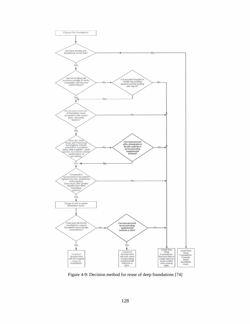
128
Figure 4-9: Decision method for reuse of deep foundations [74]
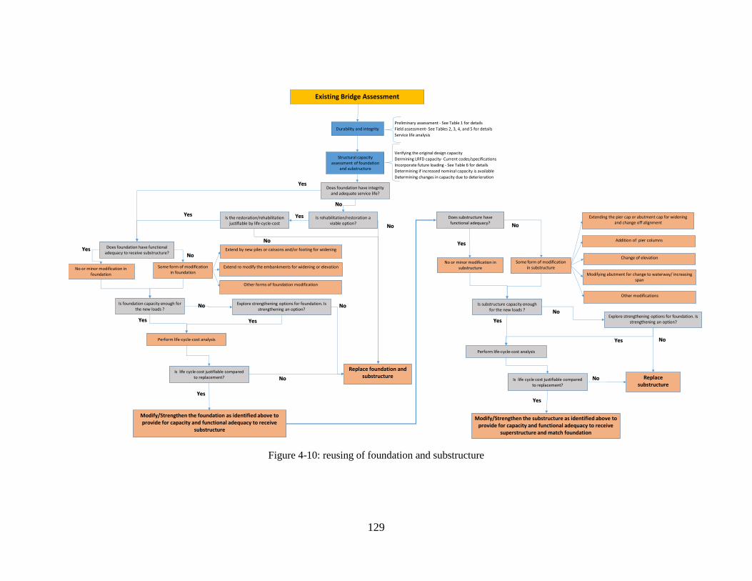
129
Figure 4-10: reusing of foundation and substructure
Preliminary assessment - See Table 1 for details
Field assessment- See Tables 2, 3, 4, and 5 for details
Service life analysis
Verifying the original design capacity
Dermining LRFD capacity- Current codes/specifications
Incorporate future loading - See Table 6 for details
Determining if increased nominal capacity is available
Determining changes in capacity due to deterioration
Existing Bridge Assessment
Durability and integrity
No or minor modification in foundation
Structural capacity assessment of foundation
and substructure
Some form of modification in foundation
Is foundation capacity enough for the new loads ?
No
Yes Does foundation have functional adequacy to receive substructure? No
Is life cycle cost justifiable compared to replacement?
Yes
Yes
Extend by new piles or caissons and/or footing for widening
Extend ro modify the embankments for widening or elevation
Other forms of foundation modification
Explore strengthening options for foundation. Is strengthening an option?
Perform life-cycle-cost analysis
Modify/Strengthen the foundation as identified above to provide for capacity and functional adequacy to receive
substructure
No or minor modification in substructure
Some form of modification in substructure
Is substructure capacity enough for the new loads ? No
Yes
Does substructure have functional adequacy? No
Is life cycle cost justifiable compared to replacement?
No
Yes
Yes
Extending the pier cap or abutment cap for widening and change off alignment
Addition of pier columns
Change of elevation
Perform life-cycle-cost analysis
Modify/Strengthen the substructure as identified above to provide for capacity and functional adequacy to receive
superstructure and match foundation
Does foundation have integrity and adequate service life?
Is the restoration/rehabilitation justifiable by life-cycle-cost
Is rehabilitation/restoration a viable option?
No
Yes
Yes
Replace foundation and substructure
Yes
No
No
Yes
No
No
Modifying abutment for change to waterway/ increasing span
Other modifications
Explore strengthening options for foundation. Is strengthening an option?
Replacesubstructure
Yes No
130
4.6.1 Life Cycle Cost Analysis
Maintenance, repair/rehabilitation, and retrofitting/modification costs for bridges or components
including the substructure are affected by age and desired remaining service life, the level and
suitability of use, and the quality and level of preventive maintenance received as well as the extent
of retrofitting and modifications to the existing structure. Other factors such as the ease of
maintenance, availability of material and service, and need to limit downtime should also be
considered. Accurate analysis requires accurate data. The Life Cycle Cost Analysis (LCCA) of
maintenance, repair, and retrofitting applications should be based on the best operating experience
and cost data available for the system being evaluated.
A common problem faced in structural maintenance is whether an existing system or component
should receive major repairs to extend its useful life, retrofitted, modified, or whether it should be
replaced with a new one. The problem may apparently contain more than two alternatives of repair
or replacement. On the bridge component level, in addition to the repair and replacement options,
several strategies comprised of various levels of repair, retrofitting/modifications and replacement
can be studied. This may arise from the fact that not all elements of bridge under consideration
are at the same condition or need the same repair/maintenance levels.
In any case, the problem can be evaluated using modified form of the TLCC (Total Life Cycle
Cost) method of LCCA for inclusion of various alternatives. If the alternatives have unequal useful
lives, the comparison should be made on an annual worth (or equivalent annual cost) basis. While
the cost of maintenance may run at higher levels for the repair and maintain option, there is no
economic advantage to pursuing replacement unless the annual value or cost is significantly less.
Costs included in the analysis should include expenses associated with the acquisition and
installation; construction that must be performed to accommodate the new components;
maintenance and future upgrades.
If a system or component is performing satisfactorily, routine maintenance should be provided to
ensure it continues to perform. On the other hand, the bridge or components may deteriorate
unexpectedly due to environmental or other causes to a level that routine maintenance would not
be able to assure their service life. In this case, special maintenance or repair activities could
become necessary. The additional cost of such special activities may justify consideration of
replacement option. When replacement is clearly required, the total life cycle cost method can
also be used to select between alternative replacement systems or components. To this, the option
of retrofitting or modifications to the structure for conforming to its desired function should be
added. The latter may involve a combination of repair/retrofitting and addition and changes to
physical and geometric envelop of the structural components. Typically, the choice is between a
replacement with a higher initial cost and a lower ongoing maintenance cost or one with a lower
initial cost and a higher maintenance cost.
Another maintenance question that might be addressed using LCCA is what level of maintenance
should be provided to produce the lowest total life-cycle cost over the service life of the system or
component? Different levels of maintenance will increase or decrease the total life cycle cost. The
analysis involves determining operating costs and benefits associated with alternative levels of
maintenance, calculating the total life cycle cost over the remaining service life, then comparing
131
results and selecting the optimum level of maintenance. Because there is limited funding available
for repair and replacement work, it is vital that agencies provide a level of preventive maintenance
which will prevent premature failures and allow the most cost-effective use of maintenance funds.
However, it is realized that cost efficiency may not be the only parameter to be considered in a
decision-making process. Position and role of a bridge structure in a highway network is one
parameter that may significantly affect the decision making. In other words, interruption in the
traffic at local and network level and importance of the road in which the bridge is located plays
also a significant role. A life cycle cost analysis of a bridge isolated from the system, though
effective and useful, would not be able to quantify all the existing factors. The LCCA results
should be evaluated in conjunction with global or system strategic considerations. These may
include events related to bridge closure and delays that may have consequences above and beyond
monetarily measurable costs.
4.6.1.1 Basic steps in LCCA
In general, steps and procedure for an overall LCCA related to bridge structures can be listed as
below:
- Characterize bridge, bridge subsystems, and its elements
- Define planning horizon, analysis scenario, and base case
- Define alternative bridge management strategies
- Specify/select appropriate deterioration models and parameters
- Estimate costs
- Calculate net present values
- Run a sensitivity analysis
- Review results (if not acceptable, modify the strategies and repeat calculations)
- Select preferred strategy
4.6.1.2 Bridge and its elements
The life cycle cost analysis in this study focuses on substructure and foundation, assuming that the
superstructure has been identified as deficient and requires replacement. The evaluation of
durability, integrity, and capacity of the existing substructure should be performed prior to the life-
cycle cost analysis to provide the necessary information.
4.6.1.3 Planning horizon, analysis scenario, and base case
Planning horizon is the service life expected from the bridge as a whole from this point on.
A wide variety of factors may influence the analysis scenarios. This include the current state of
the bridge substructure and foundation, the importance of the bridge in the transportation network,
susceptibility of the existing bridge substructure to damages causes by extraordinary events
defining the vulnerability costs are among these parameters. Adverse environmental effects

132
including sea water rise, storms, flood, earthquakes will add to the vulnerability of bridge
subsystems.
Existing traffic volume and its trend also influences the results. This will influence the current and
future cost of interruption to operation of the bridge.
Calculation of present value for various repair/replacement strategies rely heavily on the discount
rate. The discount rate should be determined based on comparable long-term projects, the real
discount rate (inflation incorporated) for this analysis.
The base case for life cycle cost analysis is normally defined as “do nothing” option and generally
includes only normal maintenance and vulnerability costs. This scenario will only be valid if the
substructure and foundation capacity at its current state is acceptable and it provides for the
functionality of the bridge without any modifications. However, depending on the results of
durability and integrity evaluation, this case, the “do nothing” option may require extensive
inspection to assure safety and is expected to impose additional costs due to potential for failures
and higher risks for extraordinary events.
4.6.1.4 Alternative bridge management strategies
Based on the current condition evaluated for substructure and foundation, and available methods
for repair, retrofit, modifications, or replacement, following strategies, similar variations or
combination of individual strategies can be selected for inclusion in the LCCA:
Base case- The case of “do nothing” that may involve some minimal repair and should include
some monitoring and inspection regimen prescribed based on the current condition. Ongoing
maintenance activities should be considered during service life to prevent significant degradation
in the condition. Potential for failure and vulnerability to natural hazard should be evaluated
accordingly.
Repair- Apply the necessary repairs to elevate the current state to a desirable level. This option
will also require certain monitoring and inspection regimen, as well as maintenance required for
upkeep. Potential for failure and vulnerability to natural hazard should be evaluated accordingly.
Repair-Strengthening- This may be a combination of some repair and also strengthening activities.
Repairs are assumed to be repeated at certain intervals due to limited durability and potential for
new damages. Strengthening shall be designed to address the capacity requirements. Potential
for failure and vulnerability need to be evaluated accordingly.
Structural and/or geometric modifications- This may involve major strengthening using additional
components and extensions for geometric compatibility. Monitoring and inspection regimen
should be prescribed according to the condition of existing components and type of the new
additions. Potential for failure and vulnerability needs to be evaluate based on the condition of the
existing substructure and expected behavior of the amended subsystem.
Replace- This strategy includes removal of existing substructure/foundation and replacing with
new. Accordingly, potential failure and vulnerability reduces or disappears. Routine inspection
can be prescribed at long intervals.
133
The strategies described above need to be customized and modified based on the state of
substructure and foundation on case-by-case basis. For example, in some cases, the foundation
may be adequate when the substructure requires repair, strengthening, or modification. In other
cases, the substructure may be adequate and only foundation requires strengthening and
modification.
4.6.1.5 Deterioration models and parameters
In one approach (BLCCA, NCHRP 483, Bridge Life Cycle Cost Analysis), the condition of the
elements is characterized in terms of a distinct set of possible “states” and possible transitions from
one state to another [75]. Element’s aging can be presented as successive transitions from state to
state based on anticipated environmental conditions, repair actions, and other parameters that can
in some cases be estimated using models similar to decay, wear, or fatigue functions. The
condition (state) of substructure and foundation elements shall be determined through evaluation
procedure described earlier. Deterioration models for concrete and steel need to be identified from
those available, or develop new models according to the need and conditions observed for the
existing substructure and foundation. Procedure or software available for life cycle condition
analysis can incorporate such deterioration model to reflect the degradation of structural health in
time, transition from one to another state, and recovery of health index resulting from repair
activities.
A health index is also introduced that indicates the need for repair/replacement. For example,
reducing the health index from its original value of 100 to threshold index of 50, signals the need
for replacement.
4.6.1.6 Cost estimates
The costs associated with the various options are divided into three groups; initial,
distributed/periodic, and vulnerability costs. The initial costs are related to installation of any
monitoring systems, repair, strengthening/modifications, or replacement. Distributed/periodic
costs are related to inspection, maintenance of the monitoring system, and future periodic repairs.
Vulnerability costs are related to the potential cost of repair/replacement to the bridge substructure
and foundation due to loss of load carrying capacity from ongoing damages such as corrosion-
fatigue and extraordinary events (hurricanes, earthquakes, flooding, etc.).
Depending whether the bridge is in the zones that are prone to natural hazards, there could be
significant probability for various structural damages, therefore, resulting in significant agency
and users’ costs. To associate costs to extraordinary events, return period and damage scenarios
need to be considered for each category and bridge vulnerability level.
With the exception of periodic future repairs, the costs in distributed/periodic and vulnerability
cost groups are estimated for the time they occur and are divided by the return interval to obtain
annual equivalent distributed costs.
Costs in each category have two elements, agency cost and users’ cost. Agency cost refers to the
actual cost of implementing an event such as contract cost for repair or inspection. Users’ cost
134
refers to cost born by the users of the bridge, i.e., drivers and cars/trucks, for delays or detours
related to activities on the bridge. Cost to businesses around the bridge can also be included.
Costs related to each strategy should be calculated using available data for every category of initial,
periodic/distributed, and vulnerability. Some research and deductions may be needed to estimate
some of the costs that are not readily available or properly formulated.
4.6.1.7 Present values
Among the costs, the initial costs for various strategies can be assumed to occur at the end of the
first year or distributed along the anticipated time required for the actions related to initial cost.
Distributed annual costs and vulnerability annual costs can be assumed to start at the end of the
first year and span over the analysis horizon. To account for the time value of the costs, present
value of all costs related to each strategy is calculated at the beginning of the first year.
Present value calculations and analysis of results can be performed using available software, or
simply use computer spreadsheets supplemented by the available formulation [75]. The analysis
software, BLCCA, that accompanies the NCHRP Report 483, Bridge Life Cycle Cost Analysis
has additional analysis and report capabilities that are very useful for presentation of the results
[75]. It accepts information on deterioration models and calculates the health index for various
strategies. Present values calculated using any of these tools for various groups of costs can be
tabulated and illustrated through charts for clarity. A sample calculation results for a
repair/replacement project related to the Luling Bridge in Louisiana, is shown in Figure 4-11 [76,
77]. Although, the repair/replacement considerations in this project was not related to
substructure, the LCCA procedure, assumption, deterioration models, cost calculation and other
estimations can be used as model for any bridge project where strategies such as repair,
replacement, and combination of repair/replacement needs to be considered.
To demonstrate the deterioration trends and the effect of corrective actions, planned or unplanned,
BLCCA software can be used to generate the variation of the health index during the planning
horizon of the project. Sample results from the sample LCCA [76, 77] is presented here for
visualization of analysis and results. For example, for the Base Case, Figure 12, deterioration is
expected to be faster and corrective actions at intervals are assumed to represent the unplanned
repair and cable replacement dictated by the vulnerability due to corrosion and fatigue process. A
health index of near 50 is when the replacements are dictated. Deterioration trend reduces with
strategies involving repair and replacement (Figure 4-13), and trend improves significantly with
Replace strategies (Figure 4-14).

135
Figure 4-6: Comparison among present value of total costs (agency+users) for various strategies [76, 77]
Figure 4-7: Health Index variation for Base Case Strategy
(a) Initial Agency and Users' Costs
1
6
10
14
19
0
5
10
15
20
25
30
35
40
Base Case Repair all Repair-Replace 1 Repair-Replace 2 Replace all
Pre
se
nt
Va
lue
($
Mil
lio
ns
)(b) Initial and Distributed Agency and Users' Costs
26
15
17
19 20
0
5
10
15
20
25
30
35
40
Base Case Repair all Repair-Replace 1 Repair-Replace 2 Replace all
Pre
se
nt
Va
lue
($
Mil
lio
ns
)
(c) Initial,Distributed, and Periodic Agency and Users' Costs
26
1719
20 20
0
5
10
15
20
25
30
35
40
Base Case Repair all Repair-Replace 1 Repair-Replace 2 Replace all
Pre
se
nt
Va
lue
($
Mil
lio
ns
)
(d) All Agency and Users' Costs
36
20 20 21 20
0
5
10
15
20
25
30
35
40
Base Case Repair all Repair-Replace 1 Repair-Replace 2 Replace all
Pre
se
nt
Va
lue
($
Mil
lio
ns
)

136
Figure 4-8: Health Index variation for Repair Strategy
Figure 4-9: Health Index variation for Replace Strategy
4.6.1.8 Sensitivity analysis
The present values of costs estimated for each strategy are sensitive to variation of several
parameters. Among those, perhaps the most influential are the discount rate and estimated event
costs. The effect of discount rate variation is pronounced for strategies that have higher
proportions of distributed, periodic and vulnerability costs. These costs are spread over the
planning horizon and therefore have been discounted for present value calculation. If the actual
discount rate is lower than that considered in this study, the present value of these costs will be

137
greater than that reported here, and vice versa. To demonstrate this effect, a sensitivity analysis
can be performed. Here, sample sensitivity analysis results for the Luling Bridge project using the
BLCCA software for variation of discount rate between 2 and 8 percent is presented (the original
rate considered for present value estimation was 3.8 percent). Figure 4-15 shows the result of
sensitivity analysis for total combined (users+agency) costs. Results show the trend described
above. The present value estimated for the Base Case which has the greatest distributed costs is
the most sensitive to discount rate variation.
Figure 4-10: Sensitivity of total combined costs to variation of discount rate
The variation of event costs also affects the total combined present values for various strategies.
For example, the initial cost variation, cost in year-1, will not affect significantly the Base Case
costs because of the very low initial cost associated with that strategy. On the other hand, variation
of initial costs will significantly affect the relationship and order of the remaining strategies
because the initial cost is a large portion of the total cost for those strategies and total combined
costs are in very close range from each other. This effect is more pronounced for the case of
variation of initial cost for the Replace strategy that has the highest initial cost. Figure 4-16 shows
a sample relationship among total combined costs of various strategies when the initial agency
cost of the Replace option varies between minus and plus 20 percent of the cost originally
considered for estimations [76, 77]. Similar trends exist when variation of initial costs of other
strategies involving repair and replacement is considered.
Variation of distributed and future cost will on the other hand affect more noticeably the strategies
that these costs form a major part of the total present value. For example variation of the inspection
costs will affect most the Base Case strategy.

138
Figure 4-11: The effect of variation of initial agency cost of Replace all strategy
4.6.1.9 Preferred strategy
With the information generated using LCCA, the bridge owner can decide on the strategy fits best
the purpose of the project. In addition to the factors considered in LCCA analysis, the bridge
owner may want to consider other socio-economic or political parameters in their decision. The
logistical importance of the bridge also may present as a strong factor. For example, bridge in the
hurricane (or other natural or manmade hazard) evacuation routes may warrant speedy strategies
even though they offer costlier option.
4.6.2 Social Impacts
Accelerated bridge construction technology can decrease the construction time for bridge
replacement projects. The impact of decreasing construction time and limiting onsite work zone
activities can ultimately decrease delay in traveling, vehicle operation costs, and risks associated
with delays and construction zone safety. This can help to prevent further depletion of natural
resources and help toward providing for a sustainable environment. These factors have been
recognized by FHWA in relation with highways and roadways construction societal impacts [78].
The main social impact of highway and bridge construction is increasing the safety in work zone
and nearby areas. The adverse effect of prolonged construction can decrease travel speed, reduce
traffic mobility, increase probability of accidents, and cause detours, that in turn would result in
extending the traffic interruptions to a larger zone within the network. These holistic impacts of
work zone can be considered as social cost of construction and should be taken into account when
selecting the construction method and type of elements and subsystems for substructure and
foundation [79]. Considering monetary value for the time of travelers, vehicle depreciation,
increasing carbon footprint, cost to businesses affected by traffic interruptions, etc., in the life cycle
cost analysis as users’ cost can incorporate most if not all societal impact in the decision making
process.

139
4.7 Methods of Retrofitting/ Strengthening Durability, integrity, and capacity evaluation may determine deficiencies in the existing bridge.
To address the deficiencies and improve bridge capacity, strengthening and retrofitting of
foundation and substructure can be designed and implemented. It should be considered that
strengthening or retrofitting to address one issue may impact other aspects of the construction.
Additionally, minor or major modifications may need to be applied to the existing foundation and
substructure to provide suitability to superstructure regarding alignment, widening, and elevation.
Some of the strengthening, retrofitting, and modification options for substructure and above
ground elements identified by the NCHRP Synthesis 505 includes increasing capacity using pier
stem widening, adding tiebacks, decrease loading on abutment with replacement of lightweight
backfill, improve soil stability using soil nail, and wall encasement of piers bent [57].
Addition of deep foundation or micro piles to increase capacity of foundation, and implementation
of global and local ground improving techniques including grouting on the tip of foundation can
increase foundation capacity.
4.7.1 Substructure
The strengthening and retrofitting methods for concrete elements as per FHWA Report [58] are
summarized in Table 4-11. As shown in this table, different methods can be used to protect the
elements from carbonation, chloride, and other harmful chemical substances. Each method extend
element life in a different way. As described in this table, cover enhancement can also be used to
enhance the strength of the elements.
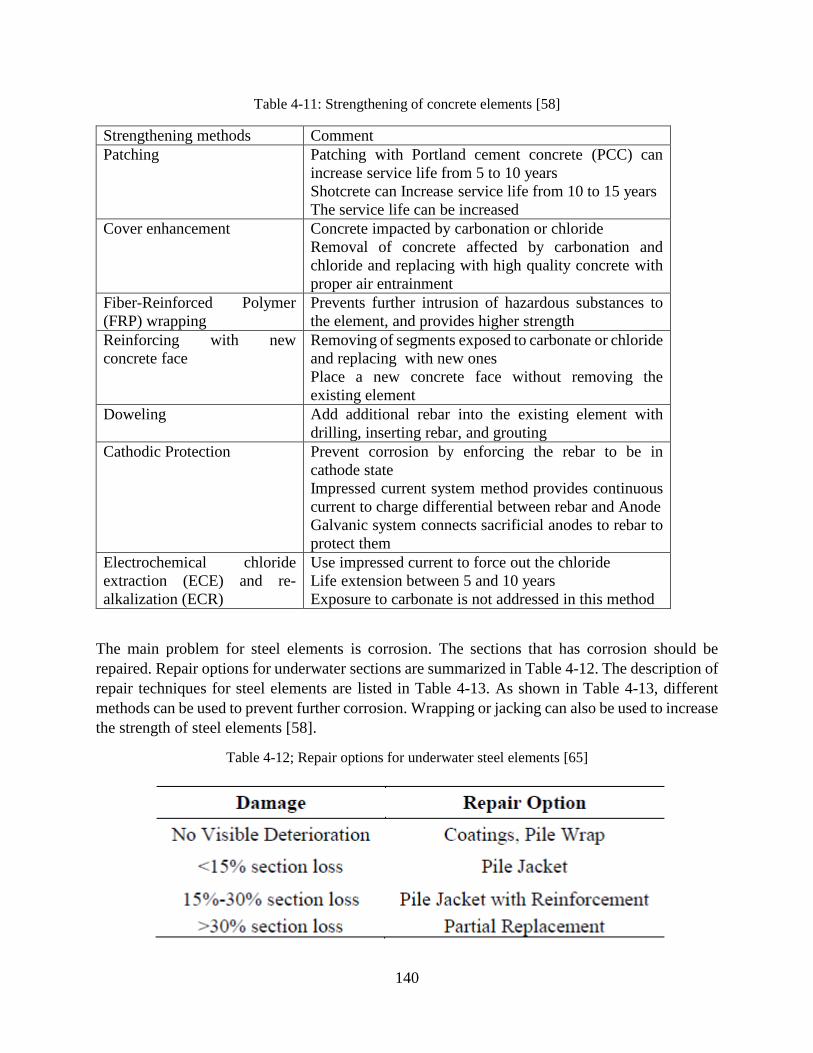
140
Table 4-11: Strengthening of concrete elements [58]
Strengthening methods Comment
Patching Patching with Portland cement concrete (PCC) can
increase service life from 5 to 10 years
Shotcrete can Increase service life from 10 to 15 years
The service life can be increased
Cover enhancement Concrete impacted by carbonation or chloride
Removal of concrete affected by carbonation and
chloride and replacing with high quality concrete with
proper air entrainment
Fiber-Reinforced Polymer
(FRP) wrapping
Prevents further intrusion of hazardous substances to
the element, and provides higher strength
Reinforcing with new
concrete face
Removing of segments exposed to carbonate or chloride
and replacing with new ones
Place a new concrete face without removing the
existing element
Doweling Add additional rebar into the existing element with
drilling, inserting rebar, and grouting
Cathodic Protection Prevent corrosion by enforcing the rebar to be in
cathode state
Impressed current system method provides continuous
current to charge differential between rebar and Anode
Galvanic system connects sacrificial anodes to rebar to
protect them
Electrochemical chloride
extraction (ECE) and re-
alkalization (ECR)
Use impressed current to force out the chloride
Life extension between 5 and 10 years
Exposure to carbonate is not addressed in this method
The main problem for steel elements is corrosion. The sections that has corrosion should be
repaired. Repair options for underwater sections are summarized in Table 4-12. The description of
repair techniques for steel elements are listed in Table 4-13. As shown in Table 4-13, different
methods can be used to prevent further corrosion. Wrapping or jacking can also be used to increase
the strength of steel elements [58].
Table 4-12; Repair options for underwater steel elements [65]

141
Table 4-13: Strengthening techniques for steel elements
Strengthening methods Comment
Encasement, jacketing, and
wrapping
Steel member can be encased in concrete or
wrapped in waterproof membrane
Prevent further corrosion
Can provide additional strength for element
Paint and coating Usually used when the element is in good
condition and original coat is not as effective as
it should be
Cathodic protection For underground or underwater elements
Impressed current or galvanic system can be
used
Furthermore, it should be noted that the existing foundation and substructure designed based on
the older design code may require new considerations per the updated design code such as seismic
and other hazard considerations [58]. Therefore, the existing foundation or substructure may face
higher load demands for which they are not designed for. For example, the columns may not have
enough confinement and shear strength to resist extreme hazard events. The following table lists
the retrofitting options to improve and increase the capacity of existing elements.
Table 4-14: Retrofitting of existing elements [58]
Retrofitting method Comment
Strengthening Increase elastic and ultimate strength of elements depending on the
extreme event loads
Improvement in
displacement
capacity
Increase inelastic behavior of element to improve displacement capacity
of the element
Force limitation Define deliberate yield points to prevent member overloading
Response
modification
Change in members load transmission by providing additional stiffness
to selected members
Site remediation by
ground
improvement
Limit liquefaction potential, site amplification, or other hazards using
ground improvement techniques
Acceptance of
damage to some
elements
Allow damage to some specific elements during hazard to prevent
structural instability of the bridge
Partial replacement Replace elements that cannot resist extreme hazards
4.7.2 Foundation
OU TO PROVIDE THEIR WORK FOR THIS SECTION
142
4.8 Extension or Amending to the Exiting Substructure and/or Foundation Usually, the use of additional elements and modification in the existing foundation and
substructure is needed to prepare required functional adequacy and suitability to the superstructure,
or to increase the capacity to address changes in the loading.
Possible options for modification and extension of substructure and foundations are described in
the next sections. Based on the selected options and modification in the substructure and
foundation, an analysis should be conducted to account for changes in loading and bridge elements.
In performing these analyses, the effect of superstructure removal, construction sequence, and
changes to the existing elements should be considered. When the existing bridge superstructure is
removed, the loading on the existing substructure and foundation will reduce or change.
Accordingly, the deformation and settlement occurred in the existing substructure and foundation
will not be completely recovered. This will make the existing substructure and foundation
elements stiffer than the new added elements constructed on new foundation, therefore causing
uneven distribution of loads between elements that needs to be considered in the analysis.
4.8.1 Substructure
The extension and modification options for the bridge substructure and foundation are:
Adding new line of column, pier, and wall between existing lines of substructures.
Extending pier cap and abutment cap to accommodate the wider superstructure or new
alignment
Pouring additional concrete adjacent to pier or extending the pier wall
Extending the footings to accommodate the new substructure elements
Addition to foundation (deep or shallow) to accommodate larger/modified footing
New pier construction to accommodate new superstructure and new configuration.
Extension, modification, and strengthening of bridge substructure is conducted to increase capacity
of substructure and/or to provide for its functional adequacy according to the predicted future
demand. One method of increasing functional adequacy is widening of existing bridges. In this
case, new substructure elements are needed to provide required capacity and new geometry. This
may require increasing the size of piers and pier caps (both by length and width) to accommodate
the new superstructure. Consequently, the footing size for the existing bridge may need be
extended as well.
4.8.2 Foundations
OU TO PROVIDE THEIR WORK FOR THIS SECTION

143
5 Survey To investigate and identify the current issues and procedures in the selection, construction, and
design of ABC bridge foundation and substructure, an online survey was distributed among the
stakeholders. The stakeholders included, but not limited to state DOTs through AASHTO
Committee on Bridge and Structures. To distribute and perform analysis on the survey results, the
online Qualtrics instrument was used. The survey had 3 following sections (Figure 5-1). Appendix
A also provides survey questionnaire.
Section 1: Administrative questionnaire
Section 2: Type of bridge construction questionnaire
Section 3: New bridge construction questionnaire
Section 4: Existing bridge construction questionnaire
In section 1, general questions were asked about the agency and the position of the person who
filled the survey. This information was saved to contact the participant in case of requiring further
details.
After filling the first sections, the participants were directed to Section 2. In this section,
participants were asked if their agency had experience in implementing ABC technique in the
construction of bridges. They were also asked if they used the ABC technique in the construction
of new bridges or/and existing bridges.
Section 3 questions were asked of participants who had experience in implementing ABC
technique in the construction of new bridges. Some detail of agency experience in implementing
ABC technique in the construction of new bridges, strategies in selecting the bridge components,
and issues in the design and construction of bridges were asked.
Finally, if the participant had experience in implementation of the ABC technique in relation with
existing bridges, section 4 questions were asked. Questions dealt with the agency’s experience in
the use of the ABC technique in the replacement, reuse, retrofitting or extension of existing
bridges. In this section, questions about the method they used to select the bridge components, the
decision-making procedure in replacement or reuse of bridges were included.

144
Figure 5-1: Survey sections
5.1 Survey Participants 20 agencies participated in filling the survey questionnaire (Figure 5-2). All of them were state
Department of transportations. The list of participants is summarized in Table 5-1. These
departments were located in different part of the United States. Figure 5-2 shows the distribution
of agencies in the United States.
Table 5-1: Survey participants
Item Agency Title
1 Rhode Island Department of Transportation Managing Engineer
2 Oklahoma DOT Director of Bridge Design
3 Indiana Department of Transportation Structures Program Manager
4 Vermont Agency of Transportation Asst. State Structures Engineer
ABC Survey
Section 1 Administrative Questionnaire
Section 2 Bridge Construction Method
Section 3New Bridge Construction
Questionnaire
Section 4 Existing Bridge Construction
Questionnaire
- Name- Agency- Title- Email- Tel.
- Experience in ABC tehnique- ABC technique used in superstructure and/or substructure- Type of superstructure system
- Factors in evaluation of existing bridge - Decision making procedure- Factors in selection of components
- Type of substructure system- Factors in selection of components- Issues in ABC technique

145
5 New Hampshire Department of Transportation Administrator Bridge Design
6 Missouri Department of Transportation State Bridge Engineer
7 Ohio Department of Transportation Administrator
8 Florida Department of Transportation Assistant State Structures Design Engineer
9 North Dakota Department of Transportation Engineer
10 Montana Department of Transportation Bridge Design Engineer
11 Nebraska Department of Transportation Assistant State Bridge Engineer
12 Michigan Department of Transportation Chief Bridge Engineer
13 Iowa Department of Transportation Chief Structural Engineer
14 North Dakota Department of Transportation Assistant Bridge Engineer
15 Wisconsin Department of Transportation Structures Development Supervisor
16 Kansas Department of Transportation Design Leader
17 Michigan Department of Transportation Foundation Analysis Engineer
18 Washington State Department of Transportation State Bridge Design Engineer
19 State of Alaska Department of Transportation Technical Engineer II
20 Texas Department of Transportation State Bridge Engineer

146
Figure 5-2: Distribution of participants in the survey
5.2 Survey Results Ninety percent of the survey participants who had experience in the application of ABC technique,
had their experience in the construction of bridge superstructure, substructure, or foundation
(Figure 5-3). 10% of respondents implemented the ABC technique only in construction of bridge
superstructure.
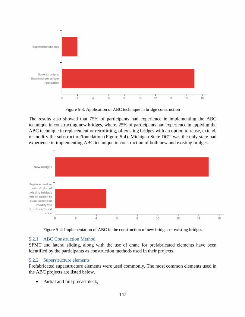
147
Figure 5-3: Application of ABC technique in bridge construction
The results also showed that 75% of participants had experience in implementing the ABC
technique in constructing new bridges, where, 25% of participants had experience in applying the
ABC technique in replacement or retrofitting, of existing bridges with an option to reuse, extend,
or modify the substructure/foundation (Figure 5-4). Michigan State DOT was the only state had
experience in implementing ABC technique in construction of both new and existing bridges.
Figure 5-4: Implementation of ABC in the construction of new bridges or existing bridges
5.2.1 ABC Construction Method
SPMT and lateral sliding, along with the use of crane for prefabricated elements have been
identified by the participants as construction methods used in their projects.
5.2.2 Superstructure elements
Prefabricated superstructure elements were used commonly. The most common elements used in
the ABC projects are listed below.
Partial and full precast deck,

148
Butted box beams,
Precast and prestressed beams with topping slab and modified shear key,
Side-by-side box beams or cored slab superstructures,
Spliced curved, U-beams,
Voided slab superstructures
5.2.3 What is needed to prepare agencies to adopt the ABC Technique?
In this section, participants were asked to describe what the agency needed to better implement
ABC. Their response is summarized below:
1. Training of contractors, agencies and DOT staff about ABC. There is a lack of knowledge
about how, where and why ABC technology can be implemented.
2. Designers need to be educated about the type of elements, connections and shapes they
can fabricate to support ABC type construction.
3. Having a guideline for designers and agencies that help them to select the best method in
the construction of a bridge based of construction duration, construction cost, and the
reason for choosing a specific method can help to facilitate the use of ABC technology.
4. Case study details are required to quantify the road user cost and ABC benefits to give
ideas on how to implement ABC. This can also can address the unfamiliarity of owners
and agencies to address this issue.
5.2.4 Substructure elements
The common substructure elements used by the participants included:
Precast caps on precast piles supporting precast superstructure elements (side-by-side box
beams/or cored/hollow slabs)
Precast concrete pier cap
Precast concrete columns
Precast concrete backwalls
Precast concrete approach slabs
Approach slabs with integrated concrete rail, concrete-filled steel pipe, and
Pile extension bents that can be constructed without a cofferdam and the pipe pile serves
as a permanent
5.2.5 Foundation Elements The most common foundation elements indicated by the participants are:
Steel piles,
Spread footings,
Drilled shafts,
Precast grade beams
Precast abutment
Pile caps
5.2.6 Factors in Selection of Substructure and Foundation Systems
The most important factors affecting the selection of substructure and foundation bridge systems
and components are:
149
Cost and speed,
Bridge span
Soil condition and location of rock under the surface of ground
Stream crossing
Critical path of bridge that determines amount of precast substructure need
Equipment
Traffic restrictions
Precast elements transfer issues
Risk mitigation
Contractor familiarity
Constructability
Design compatibility
Seismic performance
Long-term durability
Quality and safety of work
5.2.7 Guideline for selection of bridge components
Participants did not mention a particular written guideline for selection of parts for ABC projects.
However, Florida DOT stated that it is often useful to know the traffic restrictions and consider
what operations are restricted to night-work and what operations can be constructed during day-
time that usually gives the best clues of where to target the precast elements, specialized
equipment, etc. Alaska DOT also stated that Alaska Bridges and Structures Manual addresses the
design of concrete-filled steel pipe pile bents including the cold climate effects. They added that
updates are forthcoming that provide additional design guidance on this type of substructure.
5.2.8 Interaction Between Superstructure, Substructure, and Foundation in the Selection of
Components
The following restrictions were reported by the participants.
In some cases, the superstructure type may lend itself to working well with certain substructure
types. For example, prestressed tri-deck beams can be cast with integral backwalls. Or, the
foundation type will drive whether the abutments are semi-integral or integral. It was reported that
the use of semi-integral abutment complicated the details since it was required to pour the abutment
diagrams in place. The precast backwall was used to connect the abutment to the end of floor and
the approach slab.
5.2.9 ABC technology in bridge foundation construction
OU TO PROVIDE THEIR WORK FOR THIS SECTION
5.2.10 Seismic Considerations in Design of Foundation and Substructure
Most agencies reported that seismic issues were not their concern because they are not located in
seismic potential regions. However, seismic considerations were considered for substructures and
connections in states that are located in seismic region. Montana DOT stated Seismic effects were
considered for the substructures and connections, but most of our ABC structures are relatively
small, single span bridges. As a result, the seismic considerations are typically not significant.

150
Washington State DOT used integral connections at intermediate piers for seismic applications.
Also, Alaska reported that pushover analyses of the pier were conducted according to the AASTO
LRFD and Alaska DOT manual to consider seismic effects.
5.2.11 Issues in Using ABC Technology
The reported issues and concerns from agencies are summarized here.
Ohio DOT stated they need to make sure that the details allow the roadway drainage to get where
it is supposed to go. If a closed drainage system is required, details have to be consistent with
obtaining the drainage to the catch basin. Example - precast concrete elements have joints between
the elements. If these joints open up, will the roadway drainage go to places not intended. This
applies to the bridge and immediately off the bridge. Too many times, roadway drainage is an
afterthought. Where the roadway drainage does not function as designed and the drainage ends up
in a place not intended, there will be deteriorated components. Also, Montana DOT stated seal the
joints between precast elements such as backwalls to prevent water or soil intrusion is in concern.
PBES connections and demonstrations through full-scale mock-ups was another reported concern.
TX DOT stated that “incorporates provisions meant to minimize the need for maintenance into our
prefabricated elements. In particular, TxDOT relies heavily on the use of High-Performance
Concrete in precast elements. Although there are several options for achieving the HPC
requirements, in almost all cases that are accomplished by replacing some portion of the Portland
cement with Class F fly ash.”
5.2.12 Decision making procedure in selecting, replacement, reuse,
Participants reported that there was no procedure to decide whether to replace or reuse the existing
substructure/foundation. There were some rare and specific exceptions. For example, it was stated
by Rhode Island that retrofit of or replacing a column is an option if there is 60% spalled, cracked
or hollow areas. It was reported that bridges are evaluated on a case-by-case basis.
5.2.13 Retrofitting/strengthening
Few responses to this question indicated that for majority, each bridge is considered and evaluated
separately. TxDOT frequently extends existing caps on bridge widening projects.

151
6 Schedule The bar-chart below shows the schedule and work progress.
Item % Completed
Percentage of Completion of this project to Date 80
PHASE RESEARCH TASK
M A M J J A S O N D J F M A M J J A S O N D
100 100 100 100 100 100 100 100 100 100 100 100 # 100 100 100 100 100 100 100 100 100
100 100 100 100 100 100 100 100 100 100 100 100 # 100 100 100 100 100 100 100 100 100
100 100 100 100 100 100 100 100 100 100 100 100 # 100 100 100 100 100 100 100 100 100
100 100 100 100 100 100 100 100 100 100 100 100 # 100 100 100 100 100 100 100 100 100
100 100 100 100 100 100 100 100 100 100 100 100 # 100 100 100 100 100 100 100 100 100
Work completed
Work remaining
20192018
I
Task 1 - Revise Draft Outline
Task 2 - Conduct Literature Search on Topics
Identified in the Draft Outline
Task 3 - Identify Stakeholders and Conduct Survey
Task 4 -Analysis of Literature Search and Survey
Results
Task 5 - IdentificationDetermination of Issues and
Potential Solutions
Task 6 - Development of Draft Final Guide
Task 7 - Final Report
152
References 1. Culmo, M.P., Accelerated bridge construction-experience in design, fabrication and
erection of prefabricated bridge elements and systems. 2011(FHWA-HIF-12-013).
2. Culmo, M.P., Connection details for prefabricated bridge elements and systems. 2009.
Federal Highway Administration, McLean, VA(FHWA-IF-09-010).
3. Kapur, J., W.P. Yen, W. Dekelbab, A. Bardow, M. Keever, J. Sletten, D. Tobias, and M.S.
Saiidi, Best practices regarding performance of ABC connections in bridges subjected to
multihazard and extreme events. 2012(NCHRP Project 20-68A).
4. Aktan, H. and U. Attanayake, Improving Bridges with Prefabricated Precast Concrete
Systems. 2013. Michigan. Dept. of Transportation. Office of Research Administration(No.
RC-1602).
5. Roddenberry, M., Prefabricated/Precast Bridge Elements and Systems (PBES) for Off-
System Bridges:[Summary]. 2012. Florida Department of Transportation.
6. Bieschke, L. and R. Klingner, The Effect of Transverse Strand Extensions on the Behavior
of Precast Prestressed Panel Bridges. 1982. No. FHWA/TX-82/18-303-1F Final Rpt, The
Center,.
7. Culmo, M., H. Boyle, S. Nettleton, V. Chandra, M. Tadros, and J. Mallela, Engineering
Design, Fabrication and Erection of Prefabricated Bridge Elements and Systems.
2013(FHWA-HIF-17-019).
8. Precast/Prestressed Concrete Institute (PCI), Bridge Design Manual. 2001.
9. BEDILLION, N.M. A traveling relief. 2015; Available from: www.roadsbridges.com.
10. Ross, Sickling, Zimmer, and Michie, Recommended Procedure for the Safety Performance
Evaluation of Highway Features. 1993. National Cooperative Highway Research Program,
NCHRP Washington, D.C.,.
11. Sritharan, S., T. Wipf, and A. Ecklund. Development of Prefabricated Bridge Railings.
2017; Available from: https://abc-utc.fiu.edu.
12. Standard Specification for Precast Reinforced Concrete Box Sections for Culverts, Storm
Drains, and Sewers Designed According to AASHTO LRFD. C1577, A. 2017.
13. Farhangdoust, S., S.F.A. Mosawi, and A. Mehrabi, NDT METHODS APPLICABLE TO
HEALTH MONITORING OF ABC CLOSURE JOINTS. 2017. Available from: www.abc-
utc.fiu.edu.
14. Dopko, M. and B. Shafei, MATERIAL DESIGN AND STRUCTURAL CONFIGURATION
OF LINK SLABS FOR ABC APPLICATIONS. 2018. Available from: www.abc-utc.fiu.edu.
15. Moon, J., D.E. Lehman, C.W. Roeder, and H.-E. Lee, Evaluation of embedded concrete-
filled tube (CFT) column-to-foundation connections. Engineering Structures, 2013. 56: p.
22-35.
16. Lehman, D. and C. Roeder, NEW SESIMIC-RESISTING CONNECTIONS FOR
CONCRETE-FILLED TUBE COMPONENTS IN HIGH-SPEED RAIL SYSTEMS. 2018.
Available from: www.abc-utc.fiu.edu.
17. DeJong, A. and T. Hosteng, STRENGTH AND DURABILITY OF INTEGRAL ABUTMENT
CONNECTION DETAILS FOR ABC – PHASE II. 2018. Available from: www.abc-
utc.fiu.edu.
18. Tazarv, M. and S. Saiidi, DESIGN AND CONSTRUCTION OF PRECAST BENT CAPS
WITH POCKET CONNECTIONS FOR HIGH SEISMIC REGIONS. 2015. Available from:
www.abc-utc.fiu.edu.
19. Caltrans - California Department of Transportation, Bridge Design Practice. 2018.

153
20. Bentley. Inverted T beam Stem Width Calculation and Verification. 2018; Available from:
https://communities.bentley.com/.
21. Hannigan, P.J., F. Rausche, G. Likins, B. Robinson, M. Becker, and R.R. Berg, Design and
construction of driven pile foundations–Volume I. 2016. National Highway Institute (US).
22. Pei, S., N.I. Wehbe, and M. McMullen, Implementation Guidance for Accelerated Bridge
Construction in South Dakota: Research Brief. 2017. Mountain Plains Consortium.
23. DOT, O., ODOT Geotechnical Design Manual (GDM). 2018. GEO-ENVIRONMENTAL
SECTION, OREGON DEPARTMENT OF TRANSPORTATION. Available from:
https://www.oregon.gov/ODOT/GeoEnvironmental/Docs_GeologyGeotech/GDM-
08_2018.pdf.
24. DOT, V., Manual of the Structure and Bridge Division. Virginia Department of
TransportationV. Available from:
http://www.virginiadot.org/business/resources/bridge/Manuals/Part11/Chapter9.pdf.
25. DOT, W., Wisconsin Bridge Manual. 2019. Wisconsin Department of Transportation,
Wisconsin1 & 2. Available from:
https://wisconsindot.gov/dtsdManuals/strct/manuals/bridge/ch11.pdf.
26. Brown, D.A., J.P. Turner, and R.J. Castelli, Drilled shafts: Construction procedures and
LRFD design methods. 2010: US Department of Transportation, Federal Highway
Administration.
27. Dumas, C., R. Cannon, M. Lwin, S. Mansukhani, K. McLain, T. Pelnik III, A. Porbaha, S.
Putcha, D. Brown, and R. Short, Innovative Technology for Accelerated Construction of
Bridge and Embankment Foundations. 2003. FHWA-PL-03-014, Federal Highway
Administration, US Department of ….
28. Handke, J.M., Developing short-span alternatives to reinforced concrete box culvert
structures in Kansas. 2013, Kansas State University.
29. Azizinamini, A., FOLDED PLATE GIRDER BRIDGESYSTEM: A NEW HORIZON FOR
SHORT SPAN BRIDGES. 2014: American Institute of Steel Construction.
30. Azizinamini, A., Extending Maximum Length of the Folded Steel Plate Girder Bridge
System (FSPGBS), exceeding 100 ft. with capability to Incorporate Camber. 2018.
Available from: www.abc-utc.fiu.edu.
31. Azizinamini, A., E.H. Power, G.F. Myers, H.C. Ozyildirim, E.S. Kline, D.W. Whitmore,
and D.R. Mertz, Design guide for bridges for service life. 2014.
32. Umashankar, B., S.S. Mouli, and C. Hariprasad, Settlement of embankment constructed
with geofoam, in IFCEE 2015. 2015. p. 161-170.
33. Farnsworth, C., S.F. Bartlett, D. Negussey, and A.W. Stuedlein, Rapid construction and
settlement behavior of embankment systems on soft foundation soils. Journal of
geotechnical and geoenvironmental engineering, 2008. 134(3): p. 289-301.
34. FDOT STRUCTURES MANUAL. Florida Department of Transportation. 2018.
35. Marsh, M.L., Application of accelerated bridge construction connections in moderate-to-
high seismic regions. Vol. 698. 2011: Transportation Research Board.
36. Hansen, K.R. and A. Copeland, Annual asphalt pavement industry survey on recycled
materials and warm-mix asphalt usage: 2009–2012. 2013: National Asphalt Pavement
Association, 5100 Forbes Blvd., Lanham, MD 20706, (No. IS-138).
37. Badie, S.S. and M.K. Tadros, Full-depth Precast Concrete Bridge Deck Panel Systems.
Vol. 584. 2008: Transportation Research Board.

154
38. Farhangdoust, S., A.B. Mehrabi, and S.F.A. Mowsavi, NDT Methods Applicable to Health
Monitoring of ABC Closure Joints, in 27th Research Symposium - The American Society
for Non-destructive Testing (ASNT), . 2018: Orlando, Fl.
39. Hieber, D.G., J.M. Wacker, M.O. Eberhard, and J.F. Stanton, Precast concrete pier systems
for rapid construction of bridges in seismic regions. 2005. University of Washington
Seattle, Washington, USA.
40. Shafieifar, M. and A. Azizinamini, Alternative ABC Connection for Connecting Precast
Column to Cap Beam Using UHPC 2018. Available from: www.abc-utc.fiu.edu.
41. Mohebbi, A., M.S. Saiidi, and A. Itani, DEVELOPMENT AND SEISMIC EVALUATION
OF PIER SYSTEMS W/POCKET CONNECTIONS, CFRP TENDONS, AND ECC/UHPC
COLUMNS. 2017. Available from: www.abc-utc.com.
42. Hosteng, T., B. Phares, and S. Redd, Strength, durability, and application of grouted
couplers for integral abutments in accelerated bridge construction projects. 2016: Federal
Highway Administration.
43. (PCI), P.P.C.I., Precast Prestressed Concrete Piles, BM-20-04. Precast Prestressed
Concrete Institute (PCI), Chicago, IL.
44. American Association of State Highway and Transportation Officials, AASHTO LRFD
Bridge Design Specifications,. 2007: Washington, D.C.,.
45. Ofili, M., State of Accelerated Bridge Construction (ABC) in the United States. 2015.
46. Jia, J., M. Hadi, W. Orabi, and Y. Xiao. Estimating Total Cost of Bridge Construction using
Accelerated Bridge Construction (ABC) and Conventional Methods of Construction. 2016;
Available from: www.abc-utc.fiu.edu.
47. National Research Council, Innovative Bridge Designs for Rapid Renewal: ABC Toolkit.
2013: Transportation Research Board.
48. Shahrokhinasab, E., J. Ricardo, and D. Garber. PERFORMANCE COMPARISON OF IN-
SERVICE, FULL-DEPTH PRECAST CONCRETE DECK PANELS TO CAST-IN-PLACE
DECKS. 2018; Available from: www.abc-utc.fiu.edu.
49. Matsumoto, E.E., M.C. Waggoner, G. Sumen, M.E. Kreger, S.L. Wood, and J.E. Breen,
Development of a precast bent cap system. 2001(No. FHWA/TX-0-1748-2).
50. Samtani, N.C., E.A. Nowatzki, and D.R. Mertz, Selection of Spread Footings on Soils to
Support Highway Bridge Structures. 2010.
51. Farzad, M., K. Lau, D. Garber, and A. Azizinamini, CORROSION DURABILITY OF
REINFORCED CONCRETE UTILIZING UHPC FOR ABC APPLICATIONS. 2017.
Available from: www.abc-utc.fiu.edu.
52. Tang, B., Framework for prefabricated bridge elements and systems (PBES) decision-
making. 2006FHWA-IF-06-30.
53. WisDOT Bridge Manual, in Chapter 7 - Accelerated Bridge Construction. 2018, Wisconsin
Department of Transportation
54. McMullen, M. and C. Li, Feasibility Study of Developing and Creating a Standardized
Subset of Bridge Plans. 2015. Colorado Department of Transportation, Applied Research
and Innovation Branch.
55. AASHTO, Manual for Bridge Evaluation, in American Association of State Highway and
Transportation Officials. 2016: Washington, D.C.
56. Schaefer, V.R. and F. Jalinoos, Characterization of bridge foundations workshop report.
2013. United States. Federal Highway Administration. Office of Infrastructure ….
155
57. Boeckmann, A.Z. and J.E. Loehr, Current Practices and Guidelines for the Reuse of Bridge
Foundations. 2017.
58. FHWA, Foundation Reuse for Highway Bridges, in Infrastructure Office of Bridges and
Structures. 2018, Federal Highway Administration, FHWA-HIF-18-055,.
59. Strauss, J., R. Nicholls, T. Chapman, and S. Anderson, Drivers Affecting the Frequency of
Foundation Reuse and Relevance to US Cities, in Contemporary Issues In Deep
Foundations. 2007. p. 1-10.
60. Laefer, D.F. and K.-A. Farrell, A hybrid method for foundation reuse evaluation.
Environmental Geotechnics, 2014. 2(4): p. 224-236.
61. ASTM D4580/D4580M-12, Standard Practice for Measuring Delaminations in Concrete
Bridge Decks by Sounding. 2018.
62. AASHTO, LRFD Bridge design specifications. 2014, American Association of State
Highway and Transportation Officials: Washington, D.C.
63. FHWA, Recording and Coding Guide for the Structure Inventory and Appraisal of the
Nation's Bridges. 1995.
64. Florida Department of Transportation, FDOT Design Manual in 260 Bridge Structures.
2018.
65. Browne, T.M., T.J. Collins, M.J. Garlich, J.E. O’Leary, D.G. Stromberg, and K.C.
Heringhaus, Underwater Bridge Inspections. 2010. Federal Highway
Administration,(FHWA-NHI-10-027,).
66. AASHTO, Guide Specifications for LRFD Seismic Bridge Design. 2011, American
Association of State Highway and Transportation Officials,: Washington, D.C.
67. Arneson, L., L. Zevenbergen, P. Lagasse, and P. Clopper, Evaluating scour at bridges.
2012.
68. Richardson, E.V., L.J. Harrison, J. Richardson, and S. Davis, Evaluating scour at bridges.
1993.
69. Agrawal, A.K., S. El-Tawil, R. Cao, X. Xu, X. Chen, and W. Wong, A Performance-Based
Approach for Loading Definition of Heavy Vehicle Impact Events. 2018. United States.
Federal Highway Administration. Office of Research ….
70. Wright, W., B. Lattimer, M. Woodworth, M. Nahid, and E. Sotelino, Highway Bridge Fire
Hazard Assessment Draft Final Report. Virginia Polytechnic Institute and State University,
Blacksburg, VA, 2013: p. 12-85.
71. Parola, A.C., C.J. Apelt, and M.A. Jempson, Debris forces on highway bridges. 2000:
Transportation Research Board.
72. Davis, C., Sammarco, E., Williamson, E., Bridge Design Security Manual. Federal
Highway Administration, HWA-HIF-17-032. , 2017.
73. Williamson, E.B., Blast-resistant highway bridges: Design and detailing guidelines. Vol.
645. 2010: Transportation Research Board.
74. Butcher, A., J.J. Powell, and H. Skinner, Reuse of foundations for urban sites: a best
practice handbook. 2006: IHS BRE Press.
75. Hawk, H., Bridge life-cycle cost analysis. Vol. 483. 2003: Transportation Research Board.
76. Mehrabi, A., The Luling Bridge—Categorization of damages and comparison among
repair strategies. Rep. to the Louisiana Dept. of Transportation and Development, State
Project 700-45, 2007. 107.
77. Mehrabi, A. Stay cables of the Luling Bridge are to be replaced. in Proc., Int. Bridge Conf.,
Engineering Society of Western Pennsylvania, Pittsburgh. 2008.

156
78. Mallela, J. and S. Sadavisam, Work Zone Road User Costs: Concepts and Applications.
2011: US Department of Transportation, Federal Highway Administration.
79. Tabrizi, A., A. Clarke-Sather, and T. Schumacher, Bridge Retrofit or Replacement
Decisions: Tools to Assess Sustainability and Aid Decision-Making. 2016. Rutgers
University. Center for Advanced Infrastructure and Transportation.

157
APENDIX A
Survey Questionnaire
158
DEVELOPMENT OF GUIDELINES FOR SELECTION OF SUBSTRUCTURE AND FOUNDATION FOR ABC PROJECTS
Section 1
Administrative Information
▢ Name (4) ________________________________________________
▢ Agency (5) ________________________________________________
▢ Title (6) ________________________________________________
▢ Email (9) ________________________________________________
▢ Tel. (10) ________________________________________________
▢ Address (7) ________________________________________________
End of Block: DEVELOPMENT OF GUIDELINES FOR SELECTION OF SUBSTRUCTURE AND FOUNDATION FOR ABC P
Section 2
Start of Block: Type of construction

159
Q2.1 Has your agency had any experience in application of ABC technique in the construction of
a bridge?
o Yes (5)
o No (6)
Q2.2 For which of the bridge components the ABC method has been used?
o Superstructure only (1)
o Superstructure, Substructure, or foundation (2)
Q2.3 What type of superstructure system and elements and construction method have you used?
________________________________________________________________
Q2.4 What is necessary, in your opinion, for preparing your or other agencies to adopt and fully
utilize ABC?
________________________________________________________________
Q2.5 which of the following options your experience is related to? (please select all that applies).
Subsequent questions will be based on the options you select here.
▢ New bridges (1)
▢ Replacement, reuse, retrofitting, or extension of existing bridges (2)
End of Block: Type of construction
Section 3
Start of Block: New Bridges

160
Q3.2 Please describe/identify the specific system(s) or elements you have used for substructure
and foundation.
________________________________________________________________
Q3.3 Please provide input for the following questions;
▢ a) What factors have you considered in selection of substructure and foundation
systems and elements? (1) ________________________________________________
▢ b) What guideline or procedure, if any, have you used to select the substructure and
foundation systems and elements? please upload any applicable file at the end of the survey
(e.g. written guideline, procedure, etc.). (2)
________________________________________________
▢ c) Has there been any interrelation between superstructure, substructure, and foundation
that effected or limited your selection of the type of bridge elements? please explain. (4)
________________________________________________
Q3.4 Please describe if you have used any type of ABC technology in the construction of the
bridge foundation (eg. continuous flight auger piles, Micro-piling, Screw piling, Geosynthetic
reinforcement soil-integrated bridge system, etc.).
________________________________________________________________
Q3.5 What type of superstructure system and elements and construction method have you used?
________________________________________________________________
Q3.6 Did you consider the seismic effect for designing prefabricated substructure and foundation
elements and connections? Please specify.
________________________________________________________________
161
Q3.7 Do you know of any maintenance problems or other issues that impact the life-cycle
performance of the prefabricated substructure and foundation elements or ABC technology? Please
specify.
________________________________________________________________
Q3.8
What is necessary, in your opinion, for preparing your or other agencies to adopt and fully utilize
ABC?
________________________________________________________________ Q3.9 If you have a supporting file, please upload it.
End of Block: New Bridges
Section 4
Start of Block: Existing Bridge Replacement
Q4.2
a) For evaluation of existing substructure and foundation for potential reuse, retrofitting,
modification, or replacement, what factors do you consider?
b) Do you follow an established procedure to decide whether to replace or reuse the existing
substructure/foundation? Please explain methods used for the evaluation of capacity and service
life of existing substructure/foundation.
please upload any applicable file at the end of the survey (e.g. written guideline, procedure, etc.).
________________________________________________________________
Q4.3 If you used retrofitting, modification, or extension of existing substructure/foundation, please
explain the used methods.
________________________________________________________________

162
Q4.4 If substructure/foundation reuse/replacement was not an option,
▢ a) What factors do you consider to select the substructure and foundation elements and
systems? (3) ________________________________________________
▢ b) Please describe/identify the specific systems or elements you have used for
substructure and foundation system(s). (4)
________________________________________________
▢ c) Did any interrelation between superstructure, substructure, and foundation affect or
limit your selection of the type of bridge elements? please explain. (5)
________________________________________________
Q4.5 What type of superstructure system and elements and construction method have you used?
________________________________________________________________
Q4.6 Did you consider the seismic effect for designing prefabricated substructure and
foundation elements and connections? please specify.
________________________________________________________________
Q4.7 Do you know of any maintenance problems or other issues that impact the life-cycle
performance of the prefabricated substructure and foundation elements or ABC technology? please
specify.
________________________________________________________________
Q4.8 What is necessary, in your opinion, for preparing your or other agencies to adopt and fully
utilize ABC?
________________________________________________________________
Q4.9 If you have a supporting file, please upload it.
End of Block: Existing Bridge Replacement