development of magnetic gears: a review
TRANSCRIPT

Jurnal Kejuruteraan SI 1(7) 2018: 49-56https://doi.org/10.17576/jkukm-2018-si1(7)-06
Development of Magnetic Gears: A Review
(Pembangunan Gear Magentik: Satu Ulasan)
Abdullah Al Faysal*, Sallehuddin Mohamed HarisCentre for Integrated Design of Advanced Mechanical System (PRISMA),
Faculty of Engineering and Built Environment, Universiti Kebangsaan Malaysia, Bangi, Selangor, Malaysia
ABSTRACT
A gear is an essential component of most mechanical or electromechanical systems. Mechanical gears are readily used in automobile and industrial applications for torque transmission and speed variation purposes. Recent significant increase in research and development activities on magnetic gears (MG) indicates its potential in effectively replacing mechanical gears from industrial and other applications. Thus, the gradual developments of MG and magnetically geared machines have opened up innumerable opportunities for engineers and researchers. However, being a relatively new technology, the concept of MG is still unclear to many potential researchers. This paper is aimed at presenting an overview of the state of the art in MG technology, the gradual development of MG topologies, its design characteristics, optimization techniques, and a guideline for selecting suitable materials for gear construction. The MG technology is still in its early stage of development but has a huge opportunity for further improvement. The MG not only promises an ability to replace the mechanical gear, but also offers many other added advantages including increased lifespan of the machine, maintenance cost reduction, and reliable operation. Although intensive research works are being done on MGs, it is presently still unable to replace mechanical gears in industrial applications due to the holdback from the industry-readiness of MGs. The limitations and future possibilities discussed at the end of this paper could benefit readers interested in developing innovative ideas for an industry-ready version of MG.
Keywords: Magnetic gear; Axial flux; Reluctance network analysis; Finite element method; Variable gear ratio
ABSTRAK
Gear merupakan komponen penting dalam kebanyakan sistem mekanikal atau elektromekanikal. Gear mekanikal mudah digunakan dalam aplikasi kenderaan dan perindustrian untuk transmisi tork dan tujuan variasi kelajuan. Peningkatan dalam aktiviti penyelidikan dan pembangunan terkini berkaitan gear magnet (MG) menunjukkan potensinya untuk menggantikan gear mekanikal secara berkesan daripada aplikasi industri dan lain-lain. Oleh itu, perkembangan beransur-ansur MG dan mesin-mesin magnetik telah membuka peluang yang banyak untuk jurutera dan penyelidik. Walau bagaimanapun, sebagai teknologi yang agak baru, konsep MG masih belum jelas kepada penyelidik. Artikel ini bertujuan untuk membentangkan gambaran keseluruhan keadaan dalam teknologi MG, pembangunan bertahap topologi MG, ciri reka bentuk, teknik pengoptimuman, dan garis panduan untuk memilih bahan yang sesuai untuk pembinaan gear. Teknologi MG masih dalam peringkat awal pembangunan tetapi mempunyai peluang besar untuk penambahbaikan. MG bukan sahaja menjanjikan kemampuan untuk menggantikan gear mekanik, tetapi juga menawarkan banyak kelebihan tambahan lain termasuk peningkatan umur mesin, pengurangan kos penyelenggaraan, dan operasi yang boleh dipercayai. Walaupun kerja-kerja penyelidikan intensif sedang dilakukan berkaitan MG, pada masa ini masih tidak dapat menggantikan roda mekanikal dalam aplikasi perindustrian kerana penangguhan dari kesediaan industri MG. Keterbatasan dan ramalam masa depan yang dibincangkan di akhir artikel ini dapat memberi manfaat kepada pembaca yang berminat untuk mengembangkan idea-idea inovatif untuk MG versi industri yang siap sedia.
Kata kunci: Gear magnet;Fluks aksial; Analisis rangkaian engganan; Kaedah elemen terhingga; Nisbah gear boleh ubah
INTRODUCTION
Mechanical gears are extensively used in automobile and industrial machines for torque transmission in between rotational parts. Typically, a mechanical gear system comprises of a toothed wheel which meshes with another toothed wheel to transfer torque. Torque amplification or reduction from one wheel to the other occurs, depending on
the relative diameters (and hence, the number of teeth) of the meshed wheels. The ratio of the number of teeth of the driven wheel to that of the driving wheel gives the torque amplification or reduction value of the gear pair.
The meshed teeth of the gear wheels need to be in physical contact for the system to work. This results in some unwelcome problems such as vibration, noise and fatigue failure. In applications such as automobiles, such problems
JK 30 SI1(7) Bab 6.indd 49 1/24/2019 5:01:00 PM
50
are compounded as they are also contributed by other components of the vehicle. Overcoming or attenuating them is very critical as they may lead to catastrophic failure, or may undermine vehicle drivability and passenger comfort. In view of this, much research work has been done, for example, one may refer to the works of Abdullah et al. (2005), Asi (2006), Abu Bakar et al. (2008), Lukasiewicz et al. (2014) and Zhong et al. (2015).
In order to overcome the disadvantages arising from mechanical gears due to direct mechanical contacts between the rotating shafts, magnetic gears (MG) and magnetically geared machines have evolved as a realistic and practical alternative to the typical mechanical gearboxes in recent times. MGs offer lighter weight, reduced maintenance, high reliability, no wear & tear, contact free operation, no noise and higher efficiency. A study comparing the efficiencies of different types of gears showed that MGs can have efficiencies of more than 95% in terms of torque transmission from a drive gear to the driven gear (Fukuoka et al. 2013).
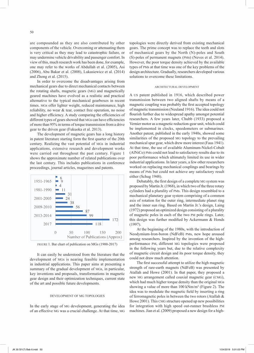
The development of magnetic gears has a long history in patent literature starting form the first quarter of the 20th century. Realizing the vast potential of MGs in industrial applications, extensive research and development works were carried out throughout the past century. Figure 1 shows the approximate number of related publications over the last century. This includes publications in conference proceedings, journal articles, magazines and patents.
topologies were directly derived from existing mechanical gears. The prime concept was to replace the teeth and slots of mechanical gears by the North (N)-poles and South (S)-poles of permanent magnets (PMs) (Neves et al. 2014). However, the poor torque density achieved by the available types of PMs at that time was one of the key problems of the design architecture. Gradually, researchers developed various solutions to overcome these limitations.
ARCHITeCTURAL DeveLOPMeNT
A US patent published in 1916, which described power transmission between two aligned shafts by means of a magnetic coupling was probably the first accepted topology of magnetic transmission (Neuland 1916). The idea could not flourish further due to widespread apathy amongst potential researchers. A few years later, Chubb (1933) proposed a vernier motor as a magnetic reduction-gear unit, which could be implemented in clocks, speedometers or submarines. Another patent, published in the early 1940s, showed some similarities of the proposed MG topology to the prevailing mechanical spur gear, which drew more interest (Faus 1941). At that time, the use of available Aluminum-Nickel-Cobalt (AlNiCo) PMs could not lead to satisfactory results due to its poor performance which ultimately limited its use in wider industrial applications. In later years, a few other researchers worked on replacing mechanical couplings and bearings by means of PMs but could not achieve any satisfactory result either (Schug 1948).
Debatably, the first design of a complete MG system was proposed by Martin Jr. (1968), in which two of the three rotary cylinders had a plurality of PMs. This design resembled to a mechanical planetary gear system comprising of a common axis of rotation for the outer ring, intermediate planet ring and the inner sun ring. Based on Martin Jr.’s design, Laing (1972) proposed an optimized design consisting of a plurality of magnetic poles in each of the two PM pole rings. Later, this design was further modified by Ackermann & Honds (1997).
At the beginning of the 1980s, with the introduction of Neodymium-Iron-boron (NdFeB) PMs, new hope aroused among researchers. Inspired by the invention of the high-performance PM, different MG topologies were proposed in the following years but, due to the relative complexity of magnetic circuit design and its poor torque density, they could not draw much attention.
The first successful attempt to utilize the high magnetic strength of rare-earth magnets (NdFeB) was presented by Atallah and Howe (2001). In that paper, they proposed a new MG arrangement called coaxial magnetic gear (CMG), which had much higher torque density than the original MGs showing a value of more than 100 kNm/m³ (Figure 2). The idea was to modulate the magnetic field by inserting a ring of ferromagnetic poles in between the two rotors (Atallah & Howe 2001). This CMG structure opened up new possibilities for integration with high speed out-runner brushless PM machines. Jian et al. (2009) proposed a new design for a high-
FIGURe 1. Bar chart of publication on MGs (1900-2017)
It can easily be understood from the literature that the development of MGs is nearing feasible implementation in industrial applications. This paper aims at presenting a summary of the gradual development of MGs, in particular, key inventions and proposals, transformations in magnetic gear design and their optimization techniques, current state of the art and possible future developments.
DeveLOPMeNT OF MG TOPOLOGIeS
In the early stage of MG development, generating the idea of an effective MG was a crucial challenge. At that time, MG
JK 30 SI1(7) Bab 6.indd 50 1/24/2019 5:01:03 PM

51
speed PM brushless generator by integrating it with a coaxial magnetic gear (CMG), which offered high torque density while driving in a low-speed and high-torque configuration. Many improved CMG topologies were invented further, based on the field modulation principle to achieve better efficiency (Li et al. 2013).
eddy currents. In recent years, emphasis has been given to the improvement of torque density in AFMGs, considering the fact that, AFMGs are capable of providing greater torque density than CMGs. This is due to the surface for magnetic field interaction being larger in AFMGs compared to CMGs (Acharya et al. 2013; Dolisy et al. 2015; Lubin et al. 2013, 2014).
In the recent past, several promising energy conversion technologies were reviewed and tested for hybrid electric vehicle (Hev) applications (Liu & Chau 2014). electronic continuously variable transmission (e-CvT) is among the most notable proposals, which offers distinct possibilities to efficiently improve the characteristics of the vehicle and the different electrical issues (Chau & Chan 2007; Liu et al. 2010). Niu et al. (2013), on the basis of harmonic spectra analysis of magnetic fields, proposed a new e-CvT system which offered a compact and brushless structure, but suffered from proper flux transmission efficiency. Liu & Chau’s (2014) proposal of an electromagnetic design for electrically controlled magnetic variable-speed gearing machine greatly improved the flux transmission efficiency. The proposed machine showed provisions for varying the gear ratios for torque and speed control along with a gear shifting mechanism for torque and speed transmission.
STRUCTURAL DeSIGN vARIATION
Analyzing the literature over the past century, several MG topologies have been found to be promising. Considering poor efficiency and complexityz in construction some of the ideas could not be developed further. Modern day MG topologies which are accepted by the researchers can be divided into three categories based on gear structure namely, concentric, harmonic and planetary MGs as shown in Figure 3.
FIGURe 2. Proposed coaxial magnetic gear (CMG)Adapted from the design of Atallah & Howe (2001)
Along with the intensive research on emerging CMGs, attention was also given to the development of axial field magnetic gears (AFMG). Mezani et al. (2006) proposed a high-performance AFMG topology for use in applications where isolation between the input and output shafts is necessary. In that paper, they showed that a torque density of more than 70 kNm/m³ can be achieved by using a gear ratio of 5.75:1 (Mezani et al. 2006). Later, Niguchi et al. (2010) published a paper on AFMG concerning the effects of eddy currents in torque transmission. The study highlighted a limitation in that transmission torque efficiency of an AFMG deteriorates while increasing the rotational speed due to the increase of
FIGURe 3. (a) Concentric, (b) harmonic and (c) planetary MGs Adapted from the design of Tlali et al. (2014)
JK 30 SI1(7) Bab 6.indd 51 1/24/2019 5:01:08 PM
52
vARIATION BASeD ON FLUx ORIeNTATION
Based on the orientation of magnetic flux, MGs can also be divided into three categories namely, radial flux magnetic gear (RFMG) or coaxial magnetic gear (CMG), disc type or axial flux magnetic gear (AFMG) and linear or transverse flux magnetic gear (TFMG) (Niguchi et al. 2010).
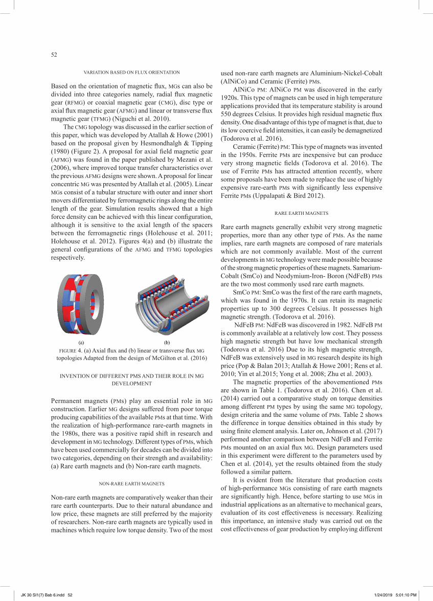
The CMG topology was discussed in the earlier section of this paper, which was developed by Atallah & Howe (2001) based on the proposal given by Hesmondhalgh & Tipping (1980) (Figure 2). A proposal for axial field magnetic gear (AFMG) was found in the paper published by Mezani et al. (2006), where improved torque transfer characteristics over the previous AFMG designs were shown. A proposal for linear concentric MG was presented by Atallah et al. (2005). Linear MGs consist of a tubular structure with outer and inner short movers differentiated by ferromagnetic rings along the entire length of the gear. Simulation results showed that a high force density can be achieved with this linear configuration, although it is sensitive to the axial length of the spacers between the ferromagnetic rings (Holehouse et al. 2011; Holehouse et al. 2012). Figures 4(a) and (b) illustrate the general configurations of the AFMG and TFMG topologies respectively.
used non-rare earth magnets are Aluminium-Nickel-Cobalt (AlNiCo) and Ceramic (Ferrite) PMs.
AlNiCo PM: AlNiCo PM was discovered in the early 1920s. This type of magnets can be used in high temperature applications provided that its temperature stability is around 550 degrees Celsius. It provides high residual magnetic flux density. One disadvantage of this type of magnet is that, due to its low coercive field intensities, it can easily be demagnetized (Todorova et al. 2016).
Ceramic (Ferrite) PM: This type of magnets was invented in the 1950s. Ferrite PMs are inexpensive but can produce very strong magnetic fields (Todorova et al. 2016). The use of Ferrite PMs has attracted attention recently, where some proposals have been made to replace the use of highly expensive rare-earth PMs with significantly less expensive Ferrite PMs (Uppalapati & Bird 2012).
RARe eARTH MAGNeTS
Rare earth magnets generally exhibit very strong magnetic properties, more than any other type of PMs. As the name implies, rare earth magnets are composed of rare materials which are not commonly available. Most of the current developments in MG technology were made possible because of the strong magnetic properties of these magnets. Samarium-Cobalt (SmCo) and Neodymium-Iron- Boron (NdFeB) PMs are the two most commonly used rare earth magnets.
SmCo PM: SmCo was the first of the rare earth magnets, which was found in the 1970s. It can retain its magnetic properties up to 300 degrees Celsius. It possesses high magnetic strength. (Todorova et al. 2016).
NdFeB PM: NdFeB was discovered in 1982. NdFeB PM is commonly available at a relatively low cost. They possess high magnetic strength but have low mechanical strength (Todorova et al. 2016) Due to its high magnetic strength, NdFeB was extensively used in MG research despite its high price (Pop & Balan 2013; Atallah & Howe 2001; Rens et al. 2010; Yin et al.2015; Yong et al. 2008; Zhu et al. 2003).
The magnetic properties of the abovementioned PMs are shown in Table 1. (Todorova et al. 2016). Chen et al. (2014) carried out a comparative study on torque densities among different PM types by using the same MG topology, design criteria and the same volume of PMs. Table 2 shows the difference in torque densities obtained in this study by using finite element analysis. Later on, Johnson et al. (2017) performed another comparison between NdFeB and Ferrite PMs mounted on an axial flux MG. Design parameters used in this experiment were different to the parameters used by Chen et al. (2014), yet the results obtained from the study followed a similar pattern.
It is evident from the literature that production costs of high-performance MGs consisting of rare earth magnets are significantly high. Hence, before starting to use MGs in industrial applications as an alternative to mechanical gears, evaluation of its cost effectiveness is necessary. Realizing this importance, an intensive study was carried out on the cost effectiveness of gear production by employing different
FIGURe 4. (a) Axial flux and (b) linear or transverse flux MG topologies Adapted from the design of McGilton et al. (2016)
INveNTION OF DIFFeReNT PMS AND THeIR ROLe IN MG DeveLOPMeNT
Permanent magnets (PMs) play an essential role in MG construction. earlier MG designs suffered from poor torque producing capabilities of the available PMs at that time. With the realization of high-performance rare-earth magnets in the 1980s, there was a positive rapid shift in research and development in MG technology. Different types of PMs, which have been used commercially for decades can be divided into two categories, depending on their strength and availability: (a) Rare earth magnets and (b) Non-rare earth magnets.
NON-RARe eARTH MAGNeTS
Non-rare earth magnets are comparatively weaker than their rare earth counterparts. Due to their natural abundance and low price, these magnets are still preferred by the majority of researchers. Non-rare earth magnets are typically used in machines which require low torque density. Two of the most
JK 30 SI1(7) Bab 6.indd 52 1/24/2019 5:01:10 PM

53
PMs in the same gear configuration (Chen et al. 2014). The objective was to find the optimum balance between the cost and performance. The per unit prices of these PMs are ever changing, so it was difficult to calculate the exact values from this study. The motive of the study was to demonstrate an idea of how this price difference affects the overall situation. Table 3 shows the findings from the work done by Chen et al. (2014).
TABLe 1. Magnetic properties of PMs (Todorova et al. 2016)
Type of PMs Br (T) Hc (KA/m) µr (BH)max (KJ/m^3) Max operating temp. (ºC)
AlNiCo 9 (LNGT8) 1.08 120 7.162 80 550
TABLe 2. Torque density comparison of different PMs (Chen et al. 2014)
Ferrite (F4450) 0.43 330.247 1.036 35 450SmCo (S3410) 1.13 795.775 1.21 231 300NdFeB 1.17-1.21 890 1.1 263-270 80 Permanent Magnet Outer rotor torque Inner rotor torque Torque densityAlNiCo 62.15 Nm 8.45 Nm 9.29 kN/m³Ferrite 31.85 Nm 4.35 Nm 4.49 kN/m³SmCo 389 Nm 53 Nm 56 kN/m³NdFeB 456 Nm 62 Nm 67 kN/m³
TABLe 3. Cost effectiveness of different PMs (Chen et al. 2014)
Permanent Magnet AlNiCo Ferrite SmCo NdFeB
Cost effectiveness 1.197 1.415 2.09 1.5(USD/Nm)
From the table it is seen that, AlNiCo is the most cost effective type to use in industrial applications. Considering the available reserves of elements required to produce AlNiCo, it is also preferred over the rare earth SmCo and NdFeB PMs. On the other hand, Ferrite PMs, although having a lower cost, is not preferred due to its poor performance when compared to AlNiCo. From Table 2, it is seen that, for the same volume of PM, AlNiCo is capable of producing almost double the torque density of Ferrite PM.
DeSIGN OPTIMIZATION TeCHNIQUeS
Design and analysis of MGs require the optimization of both, the mechanical and electro-magnetic characteristics. early researches on MGs were focused on improving the physical design rather than the performance. Also, due to the unavailability of construction materials, mechanical performance analysis was not a viable option. Due to these facts, most of the publications emphasized on the electro-mechanical characteristics for MG design. Some of the preferred optimization techniques that have been developed over time are as follows:
1. Numerical analysis based on the finite element method (FeM) (Jian & Chau 2010; Zhang & Ding 2016).
2. Analytical solution based on the sub-domain method (Lubin et al. 2013).
3. Classical electrical machine theory (Abdel-Khalik et al. 2010).
4. Reluctance network analysis (RNA) (Fukuoka et al. 2012; Lehikoinen et al. 2016; Tajima et al. 1999).
5. Harmonic spectra analysis of magnetic fields(Niu et al. 2013).
Before selecting an analysis technique, one must first consider the required computational time and the accuracy of results that can be obtained using that particular technique. The literature suggests that analytical calculations, which is based on some simplifying assumptions, require less computational time compared to numerical methods. As a result, some researchers prefer analytical calculations over numerical computations, although numerical computations like the FeM can predict more realistic results by taking into account the real geometry of the model. In other cases where the accuracy of the calculation is more important than the time involved in performing that calculation, FeM is highly preferred. Not only for electromagnetic calculations, FeM is vastly used in different mechanical and electrical systems to predict the behavior and life expectancy of a system (Rahman et al. 2008).
Aside from numerical and analytical calculations, other analysis techniques, such as RNA and harmonic spectra analysis have also been developed as they exhibit some distinct merits over other methods. RNA has emerged as one of the most practical solutions in electromagnetic calculations due to its simple analysis approach, high accuracy and relatively less computational time compared to FeA (Fukuoka et al. 2011).
In the RNA model, by implementing the idea of a network model, magnetic flux is specified by a circuit consisting of different magnetic resistance elements with lumped parameters. Using this model, the effects of eddy current and stray flux in a magnetic circuit can be predicted quite
JK 30 SI1(7) Bab 6.indd 53 1/24/2019 5:01:10 PM

54
accurately. The realistic approach used in this model helps to obtain the dynamic magnetic effects in an efficient way (Wehner et al. 2010).
FE-models for finite element analysis is the most commonly used approach for electromagnetic calculations. The dynamic and static characteristics of the electromagnetic field is calculated by employing Maxwell’s equations. The main advantage of using 3D FeA is that the exact geometry of the model can be simulated without having to make any simplifying assumptions. As a result, highly accurate results closely similar to the actual values can be obtained through this method.
Recently, the development of 2D analytical models for axial field MGs has attracted the attention of researchers. In order to analyze the performance of an AFMG, a clear understanding of the magnetic field distribution in the air gap region between the rotor and the stator is necessary. Lubin et al. (2013) developed an analytical model for computation of AFMGs which shows close agreement with results obtained from FeA. The results obtained through this method was slightly inaccurate compared to the actual result, but its simplicity means that computations can be executed much more quickly. Hence, this model can be used as a first step in design optimization.
LIMITATIONS OF CURReNT DeSIGNS AND FUTURe POSSIBILITIeS
Recently, with the improvements in MG topologies and their performances, attempts have been made to replace the mechanical gearboxes with fixed gearing ratios in wind energy production and ev applications (Chau et al. 2007; Jian et al. 2009). A direct replacement of mechanical gearboxes with magnetic gearing sets is still a complex procedure due to the lack of controllable gear ratios. At present, available MGs for commercial applications make use of PMs, where the gear ratio depends on the number of stator and rotor poles. Hence the gear ratio is fixed by the physical design of the gear. Due to the lack of variable geared MGs, it is still unsure whether MGs can replace the mechanical gears for full scale industrial applications or not. Some researchers are putting their efforts to develop industry-ready versions of variable geared magnetic machines. Development of a MG capable of replacing mechanical gears with controllable gear ratios might be the future of MG technologies.
The application of MG is not only limited to the automobile industry, but also expands to other fields of engineering. Studies are being carried out to use MGs in marine and ocean energy conversion systems (McGilton et al. 2018). MGs are also suited to a variety of applications including renewable energy and mining systems (Holm et al. 2013; Shah et al. 2007), marine propulsion systems and aerospace technology (Chau & Chan 2007; Liu et al. 2010). Further development of MGs is necessary to make them practically adaptable with other challenging environments so that it can be used in more industrial applications.
CONCLUSION
In this paper, the development of MG topologies has been discussed from the beginning of its journey. The unique characteristics, advantages and disadvantages of different gear topologies have been presented, along with the cost-effectiveness of using different PM materials. Several analysis techniques for gear design and their optimization procedures have been briefly discussed. From the current stage of development, it is clear that MGs have distinct advantages over typical mechanical gears. However, practical use of MGs in industrial applications still requires validation of readiness in the respective operations. Despite the high cost of MG production, if a viable solution can be obtained for its industrial readiness, significant changes for future development can be foreseen.
ACKNOWLeDGeMeNT
This work was supported by Universiti Kebangsaan Malaysia through the research grant number DIP-2014-038, for which the authors express their most sincere gratitude.
ReFeReNCeS
Abdel-Khalik, A. S., elshebeny, A. S. & Ahmed, S. 2010. Design and evaluation of a magnetic planetary gearbox for compact harsh environments. SPEEDAM 2010 - International Symposium on Power Electronics, Electrical Drives, Automation and Motion 1178-1182.
Abdullah, S., Yates, J.R. & Giacomin, J.A. 2005. Fatigue data editing algorithm for automotive applications. Jurnal Kejuruteraan 17: 71-84.
Abu Bakar, A.R., Ouyang, H. & Abdul Hamid, M.K. 2005. Modelling and simulation of disc brake contact analysis and squeal. Jurnal Kejuruteraan 20: 163-173.
Acharya, V. M., Bird, J. Z. & Calvin, M. 2013. A flux focusing axial magnetic gear. IEEE Transactions on Magnetics 49(7): 4092-4095.
Ackermann, B. & Honds, L. 1997. Magnetic drive arrangement comprising a plurality of magnetically cooperating parts which are movable relative to one another. U.S. Patent 5633555.
Asi, O. 2006. Fatigue failure of a helical gear in a gearbox. Engineering Failure Analysis 13(7): 1116-1125.
Atallah, K. & Howe, D. 2001. A novel high-performance magnetic gear. IEEE Transactions on Magnetics 37(4): 2844-2846.
Atallah, K., Wang, J. & Howe, D. 2005. A high-performance linear magnetic gear. Journal of Applied Physics 97(10): 26-29.
Chau, K. T. & Chan, C. C. 2007. Emerging energy-efficient technologies for hybrid electric vehicles. Proceedings of the IEEE 95(4): 821-835.
Chau, K. T., Zhang, D., Jiang, J. Z., Liu, C. & Zhang, Y. 2007. Design of a magnetic-geared outer-rotor permanent-
JK 30 SI1(7) Bab 6.indd 54 1/24/2019 5:01:11 PM

55
magnet brushless motor for electric vehicles. IEEE Transactions on Magnetics 43(6): 2504-2506.
Chen, M., Chau, K. T., Li, W. & Liu, C. 2014. Cost-effectiveness comparison of coaxial magnetic gears with different magnet materials. IEEE Transactions on Magnetics 50(2): 821-824.
Chubb, L.W. 1933. vernier motor. U.S. Patent 1894979.Dolisy, B., Mezani, S., Lubin, T. & Leveque, J. 2015. A
new analytical torque formula for axial field permanent magnets coupling. IEEE Transactions on Energy Conversion 30(3): 892-899.
Faus, H. T. 1941. Magnetic gearing. U.S. Patent 2 243 555.Fukuoka, M., Nakamura, K. & Ichinokura, O. 2011. Dynamic
analysis of planetary type magnetic gear based on reluctance network analysis. IEEE Transactions on Magnetics 47(10): 2414-2417.
Fukuoka, M., Nakamura, K. & Ichinokura, O. 2012. A method for optimizing the design of SPM type magnetic gear based on reluctance network analysis. Proceedings - 2012 20th International Conference on Electrical Machines, ICEM 2012, 30-35.
Fukuoka, M., Nakamura, K. & Ichinokura, O. 2013. Loss analysis and performance improvement of trial SPM type magnetic gear. 2013 15th European Conference on Power Electronics and Applications, EPE 2013, 1-8.
Hesmondhalgh, D. e. & Tipping, D. 1980. A multielement magnetic gear. IEE Proceedings B Electric Power Applications, 127(3): 129-138.
Holehouse, R. C., Atallah, K. & Wang, J. 2011. Design and Realization of a Linear Magnetic Gear. IEEE Transactions on Magnetics 47(10): 4171-4174.
Holehouse, R. C., Atallah, K. & Wang, J. 2012. A linear magnetic gear. Proceedings – 2012 20th International Conference on Electrical Machines, ICEM 2012, 563-569.
Holm, R. K., Berg, N. I., Walkusch, M., Rasmussen, P. O. & Hansen, R. H. 2013. Design of a magnetic lead screw for wave energy conversion. IEEE Transactions on Industry Applications, 49(6): 2699-2708.
Jian, L. & Chau, K. T. 2010. Design and analysis of a magnetic-geared electronic-continuously variable transmission system using finite element method. Progress In Electromagnetics Research 107(July): 47-61.
Jian, L., Chau, K. T. & Jiang, J. Z. 2009. A magnetic-geared outer-rotor permanent-magnet brushless machine for wind power generation. IEEE Transactions on Industry Applications 45(3): 954-962.
Johnson, M., Gardner, M. C. & Toliyat, H. A. 2017. Design comparison of ndfeb and ferrite radial flux surface permanent magnet coaxial magnetic gears. IEEE Transactions on Industry Applications 9994(c): 1-1.
Laing, N. 1972. Magnetic transmission. U.S. Patent 3645650.
Lehikoinen, A., Shah, S. B. & Arkkio, A. 2016. Time-stepping 3d-reluctance network analysis of an axial flux permanent magnet machine. Proceedings of EPNC 2016, 67-68.
Li, x., Chau, K.-T., Cheng, M. & Hua, W. 2013. Comparison of magnetic-geared permanent magnet machines. Progress In Electromagnetics Research 133(2013): 177-198.
Liu, C. & Chau, K. T. 2014. electromagnetic design of a new electrically controlled magnetic variable-speed gearing machine. Energies 7(3): 1539-1554.
Liu, C., Chau, K. T. & Jiang, J. Z. 2010. A permanent-magnet hybrid brushless integrated starter-generator for hybrid electric vehicles. IEEE Transactions on Industrial Electronics 57(12): 4055-4064.
Lubin, T., Mezani, S. & Rezzoug, A. 2013. Development of a 2-D analytical model for the electromagnetic computation of axial-field magnetic gears. IEEE Transactions on Magnetics 49(11): 5507-5521.
Lubin, T., Mezani, S. & Rezzoug, A. 2014. experimental and theoretical analyses of axial magnetic coupling under steady-state and transient operations. IEEE Transactions on Industrial Electronics 61(8): 4356-4365.
Lukasiewicz, M., Kalaczynski, T., Musial, J. & Shalapko, J.I. 2014. Diagnostics of buggy vehicle transmission gearbox technical state based on modal vibrations. Journal of Vibroengineering 16(6): 3137-3145.
Martin Jr, T.B. 1968. Magnetic transmission. U.S. Patent 3378710.
McGilton, B., Crozier, R., McDonald, A. & Mueller, M. 2018. Review of magnetic gear technologies and their applications in marine energy. IET Renewable Power Generation 12(2): 174-181.
McGilton, B., Mueller, M. & McDonald, A. 2016. Review of magnetic gear technologies and their applications in marine energy. 5th IET International Conference on Renewable Power Generation (RPG) 2016, 1-6.
Mezani, S., Atallah, K. & Howe, D. 2006. A high-performance axial-field magnetic gear. Journal of Applied Physics 99(8): 97-100.
Neuland, A. H. 1916. Apparatus for transmitting power. U.S. Patent 1 171 351. Retrieved from https://www.google.com/patents/US1171351.
Neves, C. G. C., Flores, A. F., Figueiredo, D. L. & Nunes, A. S. 2014. Magnetic gear: A review. 2014 11th IEEE/IAS International Conference on Industry Applications, 1-6.
Niguchi, N., Hirata, K., Muramatsu, M. & Hayakawa, Y. 2010. Dynamic analysis of axial-type magnetic gear employing 3-D FeM. Digests of the 2010 14th Biennial IEEE Conference on Electromagnetic Field Computation, CEFC 2010, 1-1.
Niu, S., Ho, S. L. & Fu, W. N. 2013. Design of a novel electrical continuously variable transmission system based on harmonic spectra analysis of magnetic field. IEEE Transactions on Magnetics 49(5): 2161-2164.
Pop, A.A. & Balan, H. 2013. Flux-density space-harmonics minimization for an axial-flux permanent-magnet machine. 4th International Symposium on Electrical and Electronics Engineering (ISEEE), 1-5.
JK 30 SI1(7) Bab 6.indd 55 1/24/2019 5:01:11 PM
56
Rahman, M. M., Ariffin, A. K., Jamaludin, N. & Haron, C. H. C. 2008. Finite element based life prediction of a new free piston linear generator engine mounting. Jurnal Kejuruteraan 20: 57-73.
Rens, J., Atallah, K., Calverley, S. D. & Howe, D. 2010. A Novel Magnetic Harmonic Gear. IEEE Transactions on Industry Applications 46(1): 206-212.
Schug, H. L. 1948. Magnetic coupling and bearing. U.S. Patent 2436939.
Shah, L., Cruden, A. & Williams, B. W. 2007. A magnetic gear box for application with a contra-rotating tidal turbine. Proceedings of the International Conference on Power Electronics and Drive Systems, 989-993.
Tajima, K., Sato, K., Komukai, T. & Ichinokura, O. 1999. Reluctance network analysis of an orthogonal-core type parametric induction motor. IEEE Transactions on Magnetics 35(5): 3706-3708.
Todorova, M., Mateev, v. & Marinova, I. 2016. Permanent magnets for a magnetic gear. 19th International Symposium on Electrical Apparatus and Technologies (SIELA), 1-4.
Uppalapati, K. & Bird, J. 2012. A flux focusing ferrite magnetic gear. 6th IET International Conference on Power Electronics, Machines and Drives (PEMD 2012), 1-6.
Wehner, D., Helduser, S., Weber, J. & Schoppel, G. 2010. Reluctance networks for simulation of proportional solenoids in fluid power valve systems. Fluid Power and Motion Control: FPMC 2010, 129-144.
Yin, X., Pfister, P. & Fang, Y. 2015. A Novel Magnetic Gear: Towards a Higher Torque Density. INTERMAG (2013): 4095.
Yong, L., Jingwei, x., Kerong, P. & Yongping, L. 2008. Principle and simulation analysis of a novel structure magnetic gear. 2008 International Conference on Electrical Machines and Systems 3845-3849.
Zhang, L. & Ding, Q. 2016. Design and 2D finite element analysis for a novel magnetic gear integrated brushless permanent machine. Proceedings of the World Congress on Intelligent Control and Automation (WCICA), 1726-1730.
Zhong, Z., Jiang, Z., Long, Y. & Zhan, x. 2015. Analysis on the noise for the different gearboxes of the heavy truck. Shock and Vibration, Article ID 476460.
Zhu, Z. Q., Ruangsinchaiwanich, S., Schofield, N. & Howe, D. 2003. Reduction of cogging torque in interior-magnet brushless machines. IEEE Transactions on Magnetics 39(5): 3238-3240.
*Abdullah Al FaysalSallehuddin Mohamed HarisCentre for Integrated Design of Advanced Mechanical System (PRISMA),Faculty of engineering & Built environment, Universiti Kebangsaan Malaysia, Bangi, Malaysia.
*Corresponding author; email: [email protected]
Received date: 14th March 2018Accepted date: 11th May 2018Online First date: 1st October 2018Published date: 30st November 2018
JK 30 SI1(7) Bab 6.indd 56 1/24/2019 5:01:11 PM