development of one cycle current controller using raspberry pi for 3
TRANSCRIPT

DEVELOPMENT OF ONE CYCLE CURRENT CONTROLLER USING
RASPBERRY PI FOR 3 PHASE ACTIVE POWER FILTER FOR NONLINEAR
LOAD IMPROVEMENT
MOHD HAFIZ BIN MOHAMAD SHARI
A project report submitted in partial
fulfilment of the requirement for the award of the
Master Electrical Engineering
Faculty of Electrical and Electronics Engineering
Universiti Tun Hussien Onn Malaysia
FEBRUARY 2015
V
ABSTRACT
Nowadays, Power distribution systems are faces more challenging problems of
nonlinear load form commercial building and domestic use. The problem occurs
when every single electronic appliances or electronic power supply used rectifier as a
new conversion technologies such as Switch Mode Power Supply (SMPS) and it can
be found virtually in every power electronic devices. The effect of nonlinear loads
are create harmonic current in additional to the fundamental AC current waveform
and transform the shape of the current from sine wave to some other form such as
“double-hump”, and it can affect both the distribution system equipment and the
loads connected to it. Therefore this study is proposing a solution by development of
one cycle current control (OCC) using Raspberry Pi for 3 phases Active Power Filter
where the main objective are to harmonic elimination and power quality
improvement. The model was perform in MATLAB/Simulink and also implements
the hardware by using Raspberry Pi as a digital signal processing system. The result
and analysis of the performance were explained in this report in terms of the output
current waveform and the effect of nonlinear load through the 3 phase power supply.
Finally, the harmonic compensating efficiency to the typical non-linear loads of the
approach presented is further verified by implementation of the One Cycle Current
Controller (OCC) is designed by simulation and hardware experimental results are
presented.

VI
ABSTRAK
Pada masa kini, sistem pengagihan kuasa berhadapan dengan masalah yang lebih
mencabar iaitu beban tidak linear untuk bangunan komersil dan penggunaan
domestik . Masalah ini berlaku apabila setiap perkakasan elektronik atau sumber
bekalan kuasa elektronik mengaplikasikan penerus sebagai penukaran arus ulang alik
(AU) kepada arus terus (AT) seperti Mod suis bekalan kuasa (SMPS) dan ia boleh
didapati di hampir setiap peranti elektronik kuasa. Kesan beban tidak linear telah
mewujudkan harmonik kepada bentuk asas arus ulang alik (AU) dengan mengubah
bentuk semasa daripada gelombang sinus ke bentuk lain seperti dua bonggol , dan ia
memberi kesan kepada peralatan bagi sistem agihan dan beban yang menghubungkan
dengannya. Oleh itu kajian ini mencadangkan penyelesaian dengan pembangunan
satu kitaran kawalan arus (OCC) menggunakan Raspberry Pi untuk 3 fasa penapis
kuasa aktif (APF) dengan matlamat utama adalah untuk penghapusan harmonik dan
peningkatan kualiti kuasa. Model ini dilaksanakan dengan menggunakan
MATLAB/Simulink dan juga mengaplikasikan sistem pemprosesan isyarat digital
dengan menggunakan Raspberry Pi. Keputusan dan analisis prestasi yang telah
dijelaskan dalam laporan ini dari segi bentuk gelombang keluaran arus dan kesan
terhadap beban tidak linear kepada sumber kuasa 3 fasa. Akhir sekali, kecekapan
pampasan harmonic untuk tipikal beban tidak linear melalui pendekatan satu kitaran
kawalan arus (OCC) telah dibentangkan serta disahkan keputusannya dengan
pelaksanaan simulasi dan perkakasan serta keputusan eksperimen dibentangkan.
VII
TABLE OF CONTENTS
TITLE I
DECLARATION II
DEDICATION III
ACKNOWLEDGEMENTS IV
ABSTRACT V
ABSTRAK VI
TABLE OF CONTENTS VII
LIST OF TABLES X
LIST OF FIGURES XI
LIST OF SYMBOLS AND ABBREVIATIONS XIII
CHAPTER 1 INTRODUCTION 1
1.0 Introduction 1
1.1 Project Background 1
1.2 Problem statement 2
1.3 Aim and Objectives 3
1.4 Limitation / Scope of Project 3
1.5 Thesis Outline 4
CHAPTER 2 LITERATURE REVIEW 5
2.1 Introduction 5
2.2 Nonlinear load 5
2.3 Active Power Filter (APF) 7
2.3.1 Harmonics in Power System Due to
Nonlinear Loads: 8
2.3.2 Brief Introduction to Active Power Filter: 8
2.3.3 Control techniques used for Active Power Filter 9
2.3.4 Digital Controller for Active Power Filter: 9
2.3.5 Three Phase Inverter 9
VIII
2.4 Controller Approaches for Active Power Filter 11
2.4.1 PID controller 12
2.4.2 Fuzzy logic controller 13
2.4.3 Hysteresis control 14
2.4.4 One-Cycle Control 16
2.5 Raspberry Pi 19
CHAPTER 3 METHODOLOGY 23
3.1 Introduction 23
3.2 Block Diagram 24
3.3 Linear and Nonlinear Load Design 26
3.3.1 Linear Loads 26
3.3.2 Nonlinear Loads 26
3.4 Gate Driver Design 27
3.5 Controller Design 30
3.6 Current sensor 34
3.7 Inverter Circuit Design 34
3.8 Analogue to Digital converter (ADC) 36
CHAPTER 4 DATA ANALYSIS AND RESULT 38
4.1 Introduction 38
4.1.1 Simulation analysis 38
4.1.2 Nonlinear Load Result 39
4.1.3 One-Cycle Current Control (OCC) 41
4.1.4 Active Power Filter Simulation (Inverter) 44
4.2 Open loop Analysis of hardware 46
4.2.1 Hardware testing analysis 48
4.2.2 Raspberry Pi output analysis 48
4.2.3 Gate Driver analysis 49
4.2.4 Active Power Filter circuit analysis 51
4.2.5 Linear load Analysis 53
4.2.6 Nonlinear load analysis 56
4.2.7 Input sensor for linear load and nonlinear load 58
4.2.8 Output Inverter for linear load and
Nonlinear Load 61
4.2.9 Close loop analysis 64

IX
CHAPTER 5 CONCLUSION AND RECOMMENDATIONS 67
5.1 Introduction 67
5.2 Conclusion and Discussion 67
5.3 Recommendation 69
REFERENCES 71
APPENDIX 1 74
APPENDIX 2 77

X
LIST OF TABLES
2.1 Switching State for three phase inverter. 11
2.2 Raspberry Pi’s specifications 21
3. 1 Comparison of linear and nonlinear loads. 7
3. 2 List of the components for gate driver circuit 27
3. 3 List of components for three phase inverter 35
3. 4 Calculation result for sensor and ADC 37

XI
LIST OF FIGURES
2. 1 Active Power Filter 7
2. 2 Schematic diagram for three phase switching 10
2. 3 One-Cycle Controlled Constant Frequency Switch [10] 16
2. 4 Switch Input x(t), Output and Switch Signal y(t)= X(t)K(t) [10] 17
2. 6 Raspberry Pi Controller 19
2. 7 Raspberry Pi’s hardware 20
3. 1 Block diagram of the project 24
3. 2 Circuit diagram of nonlinear load design 27
3. 3 The schematic diagram of the gate driver circuit 29
3. 4 Three-phase three-wire shunt active power filter 30
3. 5 One Cycle Current Controller (OCC) model for Phase A 32
3. 6 ACS712 Current sensor 34
3. 7 Circuit diagram of inverter (Active Power Filter) 35
3. 8 Communication Matlab and Raspberry Pi 36
4. 1 The Simulink model for One Cycle Current Controller (OCC) 39
4. 2 The Simulink diagram for Linear and Nonlinear load 40
4. 3 Current comparison waveform for linear and nonlinear load 40
4. 4 The Simulink model for One Cycle Current Controller (OCC) 41
4. 5 Current compensate result between current load harmonic, I_a and
current reference, Ia_ref. 42
4. 6 Tuning Controller result for I, PI and comparator block for I and PI 43
4. 7 PWM generator result 44
4. 8 The Simulink result for 3phase inverter circuit 45
4. 9 The OCC result for Voltage & Current Phase A (Before inject) 45
4. 10 The Simulink result for Voltage & Current Phase APF (After Inject) 46

XII
4. 11 Diagram for open loop analysis (hardware) 47
4. 12 Matlab/Simulink reference model for open loop test 47
4. 13 Diagram for Raspberry Pi output 48
4. 14 Result for Raspberry Pi output 49
4. 15 Diagram for gate driver output 49
4. 16 Result for gate driver output pulses (6 pulses) 51
4. 17 Diagram for APF output 51
4. 18 Result for APF circuit output for line to line voltage, VAB, 52
4. 19 Diagram for linear load 53
4. 20 Voltage Vs Current for linear load 54
4. 21 Three phase current for linear load 55
4. 22 Diagram for nonlinear load 56
4. 23 Result for analysis single phase current nonlinear load 57
4. 24 Result for analysis 3 phase current for nonlinear load 57
4.25 Diagram input sensor for linear load, 59
4.26 Diagram input sensor for nonlinear load 59
4. 27 Result ADC input sensor for linear load, 60
4. 28 Result ADC input sensor for nonlinear load 61
4. 29 Diagram for 3 phase current output inverter with linear load 62
4. 30 Diagram for 3 phase current output inverter with nonlinear load 62
4. 31 Result for 3 phase current output inverter for linear load, 63
4. 32 Result for 3 phase current output inverter for: Nonlinear load 63
4. 33 Closed loop diagram with one-cycle current controller for 3
phase APF with nonlinear load 64
4. 34 Result for closed loop diagram with One Cycle Current Controller
(OCC) controller for phase-AB of APF before injected to
power supply. 65
4. 35 APF current after inject current main supply 66

XIII
LIST OF SYMBOLS AND ABBREVIATIONS
APF - Active Power Filter
PID - Proportional Integral Derivative
PI - Proportional Integral
I - Integral
VFD - Variable Frequency Drives
SMPS - Switch-mode Power Supply
SPWM - Sinusoidal Pulse Width Modulation
UPS - Un-interruptible Power Supply
MOSFET - Metal Oxide Semiconductor Field Effect Transistor
IGBT - Insulated-Gate Bipolar Transistor
VSI - Voltage Source Inverter
CSI - Current Source Inverter
VSAFs - Voltage Source Active Filter
CSAFs - Current Source Active Filter
DC - Direct Current
AC - Alternative Current
VDC - Voltage DC
VAC - Voltage AC
THD - Total Harmonic Distortion
PWM - Pulse Width Modulation
FLC - Fuzzy Logic Controller
1
CHAPTER 1
INTRODUCTION
1.0 Introduction
This chapter will introduce about project background, problem statement, aim,
objectives and scopes of the development of One Cycle Current Controller (OCC)
using Raspberry Pi for 3 phase Active Power Filter (APF) for nonlinear load
improvement
1.1 Project Background
Power distribution system are faces a more challenging problem for nonlinear
load, rectifier is a nonlinear load device which generates harmonics and the major
problem in commercial building or domestic usage. [1][2] This is due primarily to
new power conversion technologies, the Switch-mode Power Supply (SMPS) is an
excellent power supply and also a highly contribution to nonlinear load, which can
be found in almost every power electronic device such as computers, servers,
telecom systems, broadcasting equipment, banking machines and other thing [1][2].
These harmonics cause an increase in level of RMS supply current, which results an
increase of power loss, heating of equipment and voltage sags [1]. APF is designed
to eliminate the majority of the harmonic current orders. IEEE 512-1992, harmonic
voltage is formed when harmonic current travels through the impedance of the
electrical system toward the lowest impedance point [3].
Nowadays the controllers that had been widely used to overcome this
problem are from adaptive and passive controller [9][12]. For an example,
2
Proportional Integral Derivatives (PID), Fuzzy Logic, Artificial Neural Network
(ANN), Sliding Mode Control (SMC), Hysteresis and One cycle current controller.
The current regulation has played an important role in current controlled pulse-
width-modulated (PWM) APF that is widely applied in high performance ac drives
[6][7]. Beside that there are several parameters that must be considered, such as the
current control technique to the nonlinear load and for this situation the One Cycle
Current Control methods is to be used. Recently, an embedded microcontroller
system such as Raspberry pi is quickly developed in many applications because it is
an open source, the price is reasonable and performs as microcomputer. The other
characteristic of Raspberry Pi it is directly interfaces to the MATLAB / Simulink by
using the Target Installer. The model will perform in MATLAB / Simulink and also
implements the simulation and hardware of one cycle Current Control method by
using Raspberry Pi as a digital signal processing system. As a result the performance
characteristics will be observed in terms of output current and effect to the nonlinear
load.
1.2 Problem statement
Rectifier in a every single electronic appliance or electronic power supply
typically one example of nonlinear load on a power system, arc discharge device
such as florescent lamp, electric welding machine or heater it will cause current in
the power system is interrupted by a switching action and the current contains
frequency component that are multiples of the power system frequency [2][5].
Distortion power factor is a measure of how much the harmonic distortion of a load
current decreases the average power transferred to the load. The effect of nonlinear
loads are create harmonic current in additional to the fundamental AC current
waveform and change the shape of the current from sine wave to some other form
such as “double-hump”, and it can affect both the distribution system equipment and
the loads connected to it.
If these scenarios happen it will create a problem to the power distribution
and consumer such as overheating of electrical distribution equipment and rotating
equipment, such as cables, transformers, standby generators and electric motors,

3
High voltages and circulating currents caused by harmonic resonance, Equipment
malfunctions due to excessive voltage distortion, Increased internal losses in
connected equipment resulting in component failure and shortened lifespan, False
operation of protection equipment and metering errors, Lower system power factor
preventing effective utilization, Voltage regulator problems on diesel generators,
Inability of automatic transfer switches to operate in closed transition [4].
1.3 Aim and Objectives
The main objective in this project is to implement a Active Power Filter (APF) based
One Cycle Current Controller (OCC) in order to reduce harmonic distortions for the
system with nonlinear load. Other proposed objectives of this project are listed
below:
1. Develop and implement an One Cycle Current Controller (OCC) method to
solve the nonlinear load affect to three phase supply.
2. Interface the MATLAB Simulink and the Raspberry Pi.
3. To control the current that supply into the three phase nonlinear load.
4. To built a low cost controller for three phase nonlinear load by using
Raspberry Pi.
1.4 Limitation / Scope of Project
The limitation and scope of this project is to study the characteristic and effect of the
harmonic of 3 phase nonlinear load and to evaluate the performance of Active Power
Filter (APF) based One Cycle Current Controller (OCC). In this project the other
scope of this project are:
1. Study of the one cylce current control technique by using Matlab/Simulink
software for the simulation and hardware development.
2. Construct the 600W APF circuit, where the maximum Voltage 60Vdc and the
maximum current 10A, in order to reduce the harmonic distortion.
3. Interface the Active Power Filter (APF) by using Matlab/simulink using
Raspberry Pi board as main controller.

4
4. Applied 3 phase rectifier as prototype of Nonlinear load with 10 Ω 50W
(Wire Wound resistor).
5. Maximum Voltage and current supply able to handle by APF are 60 V and
5A.
6. Test the APF circuit and Analysis the result.
1.5 Thesis Outline
This thesis is organized into 5 chapters which are introduction, literature reviews,
methodology, result and analysis, conclusion and recommendation.
This chapter is only the introduction of this proposed project; the chapter covers the
brief idea about problem area, aim, objective and limitation to solve the problem.
Chapter 2 will cover all the literature review about the principles of technique
implemented in the Active Power Filter (APF) methods, the brief control strategy
used in the proposed filter, commercial product and project that have been done
before.
Chapter 3 will cover the methodology of this project. The methodology is on the
work that must be done and focus in order to achieve the aim and objective specified
before.
Chapter 4 covers the simulation and experiment result using Matlab/Simulink and
Raspberry Pi and analyse the compensation performance of the proposed filter
subject to rectifier of nonlinear load. The simulation and experiments result of the
system performance have been observed.
The last chapter will summarize all the works that has been done in this project. This
chapter will summarize the problems faced during the project as well as the solution
found to handle the problems occurred for future works that can be done to improve
the system.

5
CHAPTER 2
LITERATURE REVIEW
2.1 Introduction
This chapter will introduce about the previous project or research done before about
nonlinear load, Active Power Filter, Three phase inverter Design, Raspberry Pi as
controller. The research covers the usage of Matlab and Raspberry Pi for testing and
the acquire result. This chapter will emphasize the importance of this project and the
differences between it with other projects.
2.2 Nonlinear load
Nonlinear load are the biggest problem to solve because it create harmonic
currents in addition to the fundamental frequency (original) AC current [2][4]. The
current waveform does not conform to that the applied voltage or where a change is
not proportional to change in applied voltage and it considered nonlinear load if its
impedance changes with the applied voltage. The changing impedance that means
the current drawn by the nonlinear load will not be sinusoidal even when it is
connected to sinusoidal voltage. These non-sinusoidal currents contain harmonic
currents that interact with the impedance of the power distribution system to create
voltage distortion that can affect both the distribution system equipment and the
loads connected to it exactly consumer [4].
The most common form of distorted current is a pulse waveform with a high
crest factor inside fundamental frequency. The SMPS is one such load since it
consists of a 2-pulse rectifier bridge to convert AC to DC and a large filter capacitor
6
on its DC bus. The SMPS draws current in short, high-amplitude pulses that occur
right at the positive and negative peaks of the voltage. Typically these high current
pulses will cause clipping or flat-topping of the 230VAC supply voltage. The
“double-hump” current waveform of the 6-pulse rectifier in a VFD also will cause
clipping or flat-topping of the 415V distribution system.[4]
Harmonics produce an increase in the resistance of the conductor and in turn,
an abnormal common mode (neutral-ground) voltage difference and this will cause
undesirable ground loops to occur. The electronic power supply is to transform an
AC into a DC, their power source takes its current as portions of the 50 Hz sine wave
to become deformed and multiple frequencies of 50 Hz are formed. Often, single
phase loads produce triplets (3rd, 9th, etc.), while three phase loads produce 5th and
7th harmonics. Therefore, electric equipment and installations which are designed to
operate at 50 Hz, can become damaged or unbalanced due to these harmonic
frequencies which are different than the fundamental (50 Hz). The principal problem
that arises is the overheating of equipment or conductors.[4]
In an electric circuit, a nonlinear element or nonlinear load device is an
electrical element which does not have a linear relationship between current, i and
voltage, V. Diode is a simple example, the current i through a diode is a nonlinear
function of the voltage, V across of its terminal. Nonlinear elements are avoided in
some electronic circuits, called linear load circuit, because they have the potential to
distort electrical signal. Other examples of nonlinear elements are transistor and
other semiconductor devices, vacuums tube and iron core inductors and transformers
when operated above their saturation current. Examples of nonlinear loads devices
are rectifiers (power supplies, UPS units, discharge lighting); adjustable speed motor
drives, ferromagnetic devices, DC motor drives and arcing equipment.
7
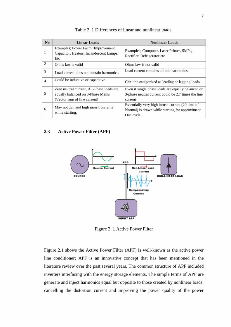
Table 2. 1 Differences of linear and nonlinear loads.
No Linear Loads Nonlinear Loads
1 Examples; Power Factor Improvement
Capacitor, Heaters, Incandescent Lamps.
Etc
Examples; Computer, Laser Printer, SMPs,
Rectifier, Refrigerator etc
2 Ohms law is valid Ohms law is not valid
3 Load current does not contain harmonics. Load current contains all odd harmonics
4 Could be inductive or capacitive. Can’t be categorized as leading or lagging loads.
5 Zero neutral current, if 1-Phase loads are
equally balanced on 3-Phase Mains
(Vector sum of line current)
Even if single phase loads are equally balanced on
3-phase neutral current could be 2.7 times the line
current
6 May not demand high inrush currents
while starting.
Essentially very high inrush current (20 time of
Normal) is drawn while starting for approximant
One cycle.
2.3 Active Power Filter (APF)
Figure 2. 1 Active Power Filter
Figure 2.1 shows the Active Power Filter (APF) is well-known as the active power
line conditioner; APF is an innovative concept that has been mentioned in the
literature review over the past several years. The common structure of APF included
inverters interfacing with the energy storage elements. The simple terms of APF are
generate and inject harmonics equal but opposite to those created by nonlinear loads,
cancelling the distortion current and improving the power quality of the power
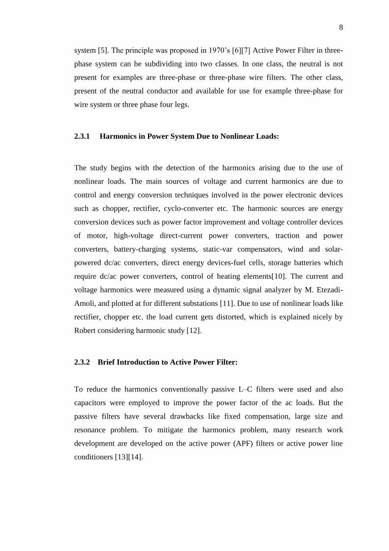
8
system [5]. The principle was proposed in 1970’s [6][7] Active Power Filter in three-
phase system can be subdividing into two classes. In one class, the neutral is not
present for examples are three-phase or three-phase wire filters. The other class,
present of the neutral conductor and available for use for example three-phase for
wire system or three phase four legs.
2.3.1 Harmonics in Power System Due to Nonlinear Loads:
The study begins with the detection of the harmonics arising due to the use of
nonlinear loads. The main sources of voltage and current harmonics are due to
control and energy conversion techniques involved in the power electronic devices
such as chopper, rectifier, cyclo-converter etc. The harmonic sources are energy
conversion devices such as power factor improvement and voltage controller devices
of motor, high-voltage direct-current power converters, traction and power
converters, battery-charging systems, static-var compensators, wind and solar-
powered dc/ac converters, direct energy devices-fuel cells, storage batteries which
require dc/ac power converters, control of heating elements[10]. The current and
voltage harmonics were measured using a dynamic signal analyzer by M. Etezadi-
Amoli, and plotted at for different substations [11]. Due to use of nonlinear loads like
rectifier, chopper etc. the load current gets distorted, which is explained nicely by
Robert considering harmonic study [12].
2.3.2 Brief Introduction to Active Power Filter:
To reduce the harmonics conventionally passive L–C filters were used and also
capacitors were employed to improve the power factor of the ac loads. But the
passive filters have several drawbacks like fixed compensation, large size and
resonance problem. To mitigate the harmonics problem, many research work
development are developed on the active power (APF) filters or active power line
conditioners [13][14].
9
2.3.3 Control techniques used for Active Power Filter
Designing a suitable controller for an APF is very important. A number control
strategies such as instantaneous reactive power theory initially developed by Akagi et
al. [15], synchronous frame d–q theory [16], synchronous detection method [17],
notch filter and fuzzy logic controller method are used in the development of three-
phase AFs and the gate pulses are generated by current control technique like
sinusoidal pulse width modulation (SPWM), triangular PWM, hysteresis current
control technique [18].
2.3.4 Digital Controller for Active Power Filter:
Advancement in microelectronics has motivated new directions for APF design
starting from the use of analogue and digital components to microprocessors,
microcontrollers, digital signal processors (DSP’s) [17][18] and FPGA
implementation [19][20]. Further, these developments have made it possible to use
different control algorithm such as proportional integral (P-I), fuzzy logic etc. for
improving the steady state and dynamic performance of APFs. By implementing this
performance, response as well as the cost is efficient compare to the analogue one.
2.3.5 Three Phase Inverter
Inverter is a device that transforms Direct Current (DC) to Alternating Current (AC),
by switching the DC input supply (voltage or current).in predetermined sequences to
generate AC (voltage or current). Inverters function as electrical controller
equipment from the power produced by a renewable energy source such as solar
panel, wind turbine, hydroelectric, tidal wave turbine and etc. The typical
applications of an inverter are un-interruptible power supply (UPS), tractions and
VHDC, industrial (induction motor) drives. There are 3 major circuit or components
to complete inverter as a device; DC supply is storage energy, Gate circuit is an
isolated circuit to protect controller being damage from surge, overload voltage or
10
current and switching circuit is to perform a DC supply switching follow controller
output form.
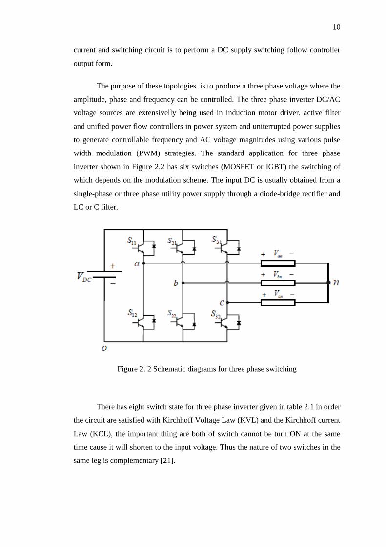
The purpose of these topologies is to produce a three phase voltage where the
amplitude, phase and frequency can be controlled. The three phase inverter DC/AC
voltage sources are extensivelly being used in induction motor driver, active filter
and unified power flow controllers in power system and uniterrupted power supplies
to generate controllable frequency and AC voltage magnitudes using various pulse
width modulation (PWM) strategies. The standard application for three phase
inverter shown in Figure 2.2 has six switches (MOSFET or IGBT) the switching of
which depends on the modulation scheme. The input DC is usually obtained from a
single-phase or three phase utility power supply through a diode-bridge rectifier and
LC or C filter.
Figure 2. 2 Schematic diagrams for three phase switching
There has eight switch state for three phase inverter given in table 2.1 in order
the circuit are satisfied with Kirchhoff Voltage Law (KVL) and the Kirchhoff current
Law (KCL), the important thing are both of switch cannot be turn ON at the same
time cause it will shorten to the input voltage. Thus the nature of two switches in the
same leg is complementary [21].
11
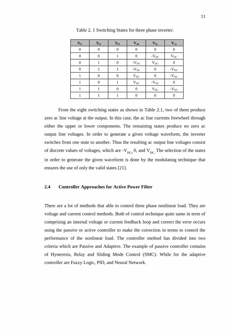
Table 2. 1 Switching States for three phase inverter.
S11 S12 S13 Vab Vbc Vca
0 0 0 0 0 0
0 0 1 0 -VDC VDC
0 1 0 -VDC VDC 0
0 1 1 -VDC 0 -VDC
1 0 0 VDC 0 -VDC
1 0 1 VDC -VDC 0
1 1 0 0 VDC -VDC
1 1 1 0 0 0
From the eight switching states as shown in Table 2.1, two of them produce
zero ac line voltage at the output. In this case, the ac line currents freewheel through
either the upper or lower components. The remaining states produce no zero ac
output line voltages. In order to generate a given voltage waveform, the inverter
switches from one state to another. Thus the resulting ac output line voltages consist
of discrete values of voltages, which are -VDC, 0, and V
DC. The selection of the states
in order to generate the given waveform is done by the modulating technique that
ensures the use of only the valid states [21].
2.4 Controller Approaches for Active Power Filter
There are a lot of methods that able to control three phase nonlinear load. They are
voltage and current control methods. Both of control technique quite same in term of
comprising an internal voltage or current feedback loop and correct the error occurs
using the passive or active controller to make the correction in terms to control the
performance of the nonlinear load. The controller method has divided into two
criteria which are Passive and Adaptive. The example of passive controller contains
of Hysteresis, Relay and Sliding Mode Control (SMC). While for the adaptive
controller are Fuzzy Logic, PID, and Neural Network.
12
2.4.1 PID controller
PID controller can be attributed partly to their robust performance in a wide range of
operating conditions and partly for their practicality engineers can operate them in a
simple and straightforward manner. Proportional-Integral-Derivative (PID) controller
is prominent for its simplicity. [29]. A PI controller is a common mechanism used in
industrial control applications. A PID controller is capable used for regulation of
temperature, pressure, flow, speed and other process variables. PID controlled
system is a combination of three elements which are proportional, integral and
derivative. Equation 2.1, describing u(t) as the controller output, the final form of the
PID algorithm is:
𝑢(𝑡) = 𝑀𝑉(𝑡) = 𝐾𝑝𝑒(𝑡) + 𝐾𝑖 ∫ 𝑒(𝜏)𝑑𝜏 + 𝐾𝑑𝑑
𝑑𝑡
𝑡
0𝑒(𝑡) (2.1)
WHERE,
𝑒 = 𝑒𝑟𝑟𝑜𝑟
𝜏 = 𝑡𝑖𝑚𝑒 𝑜𝑟 𝑖𝑛𝑠𝑡𝑎𝑛𝑡𝑎𝑛𝑒𝑜𝑢𝑠 𝑡𝑖𝑚𝑒
Tuning parameter
𝐾𝑝 = 𝑝𝑟𝑜𝑝𝑜𝑟𝑡𝑖𝑜𝑛𝑎𝑙 𝑔𝑎𝑖𝑛
𝐾𝑖 = integral gain
𝐾𝑑 = 𝑑𝑒𝑟𝑖𝑣𝑎𝑡𝑖𝑣𝑒 𝑔𝑎𝑖𝑛
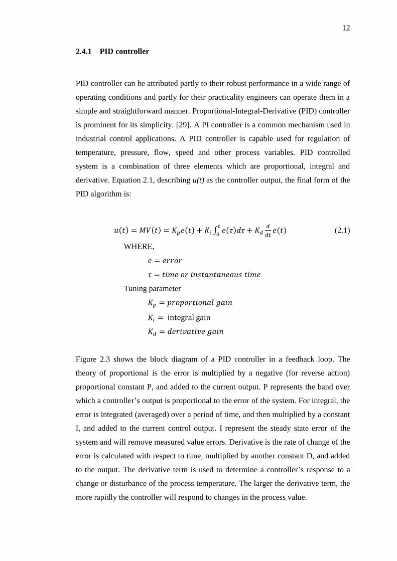
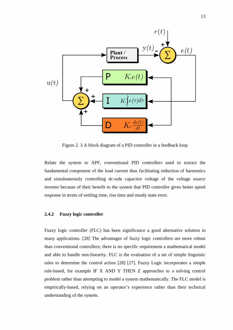
Figure 2.3 shows the block diagram of a PID controller in a feedback loop. The
theory of proportional is the error is multiplied by a negative (for reverse action)
proportional constant P, and added to the current output. P represents the band over
which a controller’s output is proportional to the error of the system. For integral, the
error is integrated (averaged) over a period of time, and then multiplied by a constant
I, and added to the current control output. I represent the steady state error of the
system and will remove measured value errors. Derivative is the rate of change of the
error is calculated with respect to time, multiplied by another constant D, and added
to the output. The derivative term is used to determine a controller’s response to a
change or disturbance of the process temperature. The larger the derivative term, the
more rapidly the controller will respond to changes in the process value.
13
Figure 2. 3 A block diagram of a PID controller in a feedback loop
Relate the system to APF, conventional PID controllers used to extract the
fundamental component of the load current thus facilitating reduction of harmonics
and simultaneously controlling dc-side capacitor voltage of the voltage source
inverter because of their benefit to the system that PID controller gives better speed
response in terms of settling time, rise time and steady state error.
2.4.2 Fuzzy logic controller
Fuzzy logic controller (FLC) has been significance a good alternative solution in
many applications. [28] The advantages of fuzzy logic controllers are more robust
than conventional controllers; there is no specific requirement a mathematical model
and able to handle non-linearity. FLC is the evaluation of a set of simple linguistic
rules to determine the control action [28] [27]. Fuzzy Logic incorporates a simple
rule-based, for example IF X AND Y THEN Z approaches to a solving control
problem rather than attempting to model a system mathematically. The FLC model is
empirically-based, relying on an operator’s experience rather than their technical
understanding of the system.
14
The desired inverter switching signals of the shunt active filter are determined
according the error between the compensate currents and reference currents.
According [27] produced a paper on Fuzzy Logic controller for shunt Active Power
Filter; the paper presents Active Power Filter based in detection load current and
harmonic voltage at the point of installation by using the fuzzy logic method and to
improve compensation capability of APF. The shunt APF is implemented with PWM
current controlled voltage source inverter and switching patterns are generated
through a fuzzy logic control. A fuzzy logic-based PWM control technique is used to
generate the gating signals. Switching signal obtained [27] after proper amplification
and isolation are given to the switching devices of the PWM converter. The DC link
capacitor voltage is maintained constant by a fuzzy logic controller. Fuzzy logic is
characterized by seven sets of membership function for each input and output
variable by using Mamdani-type min operator and defuzzification using the centroid
method. The performance of fuzzy logic controller is found to be excellent, total
harmonic distortion is (THD) reduced and improve by tuning the fuzzy rule based
using an expert view to produce more effectiveness and accuracy of controller.
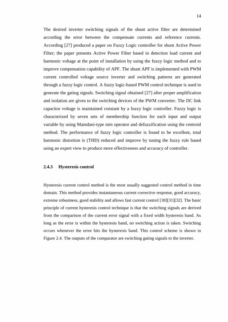
2.4.3 Hysteresis control
Hysteresis current control method is the most usually suggested control method in time
domain. This method provides instantaneous current corrective response, good accuracy,
extreme robustness, good stability and allows fast current control [30][31][32]. The basic
principle of current hysteresis control technique is that the switching signals are derived
from the comparison of the current error signal with a fixed width hysteresis band. As
long as the error is within the hysteresis band, no switching action is taken. Switching
occurs whenever the error hits the hysteresis band. This control scheme is shown in
Figure 2.4. The outputs of the comparator are switching gating signals to the inverter.
15
Figure 2. 4 Hysteresis Control Techniques
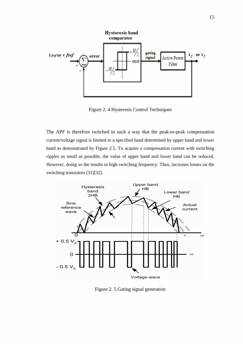
The APF is therefore switched in such a way that the peak-to-peak compensation
current/voltage signal is limited to a specified band determined by upper band and lower
band as demonstrated by Figure 2.5. To acquire a compensation current with switching
ripples as small as possible, the value of upper band and lower band can be reduced.
However, doing so the results in high switching frequency. Thus, increases losses on the
switching transistors [31][32].
Figure 2. 5 Gating signal generation
16
2.4.4 One-Cycle Control
One Cycle Control (OCC) is the term used to describe a nonlinear control technique
invented by Keyue Smedley and Slobodan Cuk because switches are nonlinear
systems, the idea is that a pulsed nonlinear control should provide faster dynamic
response and reject input perturbations better than linear control since the nonlinear
control matches the system [23][24]. One Cycle Current Controller (OCC) technique
able to be implemented under constant off time, constant on time, constant-
frequency, or variable by adjustable time on and time off switches, constant-
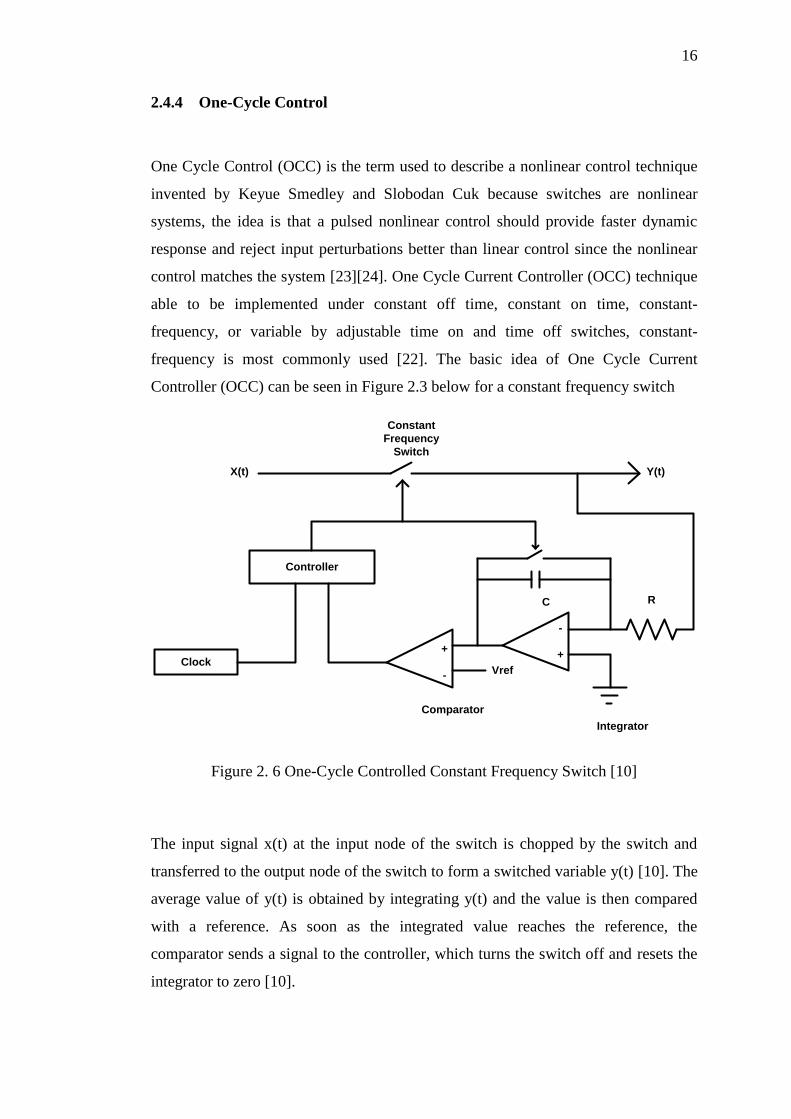
frequency is most commonly used [22]. The basic idea of One Cycle Current
Controller (OCC) can be seen in Figure 2.3 below for a constant frequency switch
Controller
Clock
Constant
Frequency
Switch
X(t) Y(t)
Vref
Comparator
Integrator
RC
-
++
-
Figure 2. 6 One-Cycle Controlled Constant Frequency Switch [10]
The input signal x(t) at the input node of the switch is chopped by the switch and
transferred to the output node of the switch to form a switched variable y(t) [10]. The
average value of y(t) is obtained by integrating y(t) and the value is then compared
with a reference. As soon as the integrated value reaches the reference, the
comparator sends a signal to the controller, which turns the switch off and resets the
integrator to zero [10].

17
A switch, constant frequency, constant ON time, constant OFF time or variable as is
defined as operating under a function k (t) at frequency 𝑓𝑠 =1
𝑇𝑠 [23]:
𝑘(𝑡) = {1 0 < 𝑡 < 𝑇𝑂𝑁 0 𝑇𝑂𝑁 < 𝑡 < 𝑇𝑠
(2.2)
In each cycle, the switch is on for a time duration TON and is OFF for a time duration
TOFF, where TON + TOFF = Ts. The duty-ratio d = 𝑇𝑂𝑁
𝑇𝑠 is modulated by an analogue
control reference Vref(t). The input signal to the switch is x(t) to produce an output
y(t) with the same frequency and pulse width as k(t), with x(t) as the envelope of y(t)
as seen in Figure 2.4
t
k(t)
x(t) Switch Y(t) = k(t) X(t)
Ts
Ton Toff
t
t
t
Figure 2. 7 Switch Input x(t), Output and Switch Signal y(t)= X(t)K(t) [10]
Assuming that the switch frequency fs is much higher than the frequency bandwidth
of x(t) or Vref(t), the effective output value y(t) is equal to the average value over a
switch cycle:
𝑦(t) =1
𝑇𝑠∫ 𝑥(𝑡)𝑑𝑡 ≈𝑇𝑠
0𝑥(𝑡)
1
𝑇𝑠∫ 𝑑𝑡 = 𝑥(𝑡)𝑇𝑂𝑛
0𝑑𝑡 = 𝑥(𝑡)𝑉𝑟𝑒𝑓(𝑡) (2. 3)
Thus, the output signal y(t) is a product of the input signal x(t) and the control Vref(t)
making the switch nonlinear. If the control signal is constant, for example Vref(t) =
18
D, then the output becomes Dx(t), as is the case in digital signal processing. For
power processing applications, x(t) usually represents the power, while Vref(t) is the
signal to be amplified. Ideally, the input power x(t) is constant, but in reality there are
perturbations causing disturbances to the output y(t) also. If the switch duty ratio is
modulated such that in each cycle the integration of the chopped waveform at the
switch output is exactly equal to the integration of the control signal, i.e.:
∫ 𝑥(𝑡)𝑑𝑡 =𝑇𝑜𝑛
0∫ 𝑉𝑟𝑒𝑓(𝑡)𝑑𝑡𝑇𝑂𝑛
0 ( 2. 4)
Then the output signal becomes instantaneously controlled within one cycle:
𝑦(t) =1
𝑇𝑠∫ 𝑥(𝑡)𝑑𝑡𝑇𝑜𝑛
0=
1
𝑇𝑠∫ 𝑉𝑟𝑒𝑓(𝑡)𝑑𝑡 = 𝑉𝑟𝑒𝑓(𝑡) 𝑇𝑠
0 (2. 5)
Since the switching frequency fs, is much higher than the time-varying reference
voltage, the reference can be seen as constant in one period, thus simplifying the
above equation to:
𝑦(𝑡) = 𝑉𝑟𝑒𝑓 (2. 6)
Thus, the switch is able to reject any input disturbances since it does not depend on
x(t) and is able to linearly pass Vref, turning a nonlinear switch into a linear
switch.[23]

19
2.5 Raspberry Pi
A Raspberry Pi is a small, credit-card sized microcomputer developed by Raspberry
Pi Foundation, UK. This single boarded computer was developed with aim of
teaching the basics of computer science and programming to school students all
around the world. Although a microcontroller, like Arduino, is trendy for prototyping
projects, a Raspberry Pi is quite different from the popular microcontroller. Actually,
it is more like a computer than an Arduino.
Figure 2. 8 Raspberry Pi’s Controller
2.5.1 Hardware and specifications
Raspberry Pi is found in two versions. Model A and Model B. Although Model A is
cheaper than Model B, there are some other differences in these two versions of
Raspberry Pi. Model A has a 256MB memory, comes with a single USB port and
20
does not have any Ethernet port whereas model B has a 512MB memory, 2 USB
ports, and an Ethernet port as well.
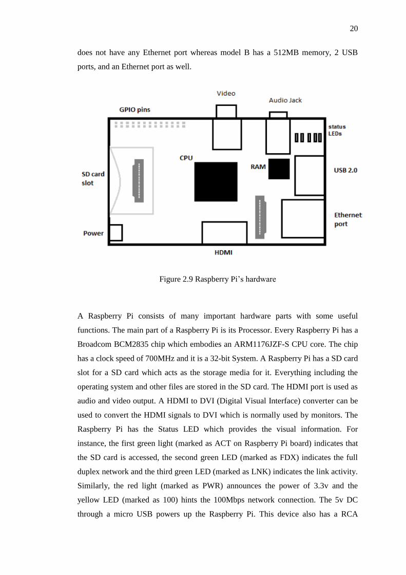
Figure 2.9 Raspberry Pi’s hardware
A Raspberry Pi consists of many important hardware parts with some useful
functions. The main part of a Raspberry Pi is its Processor. Every Raspberry Pi has a
Broadcom BCM2835 chip which embodies an ARM1176JZF-S CPU core. The chip
has a clock speed of 700MHz and it is a 32-bit System. A Raspberry Pi has a SD card
slot for a SD card which acts as the storage media for it. Everything including the
operating system and other files are stored in the SD card. The HDMI port is used as
audio and video output. A HDMI to DVI (Digital Visual Interface) converter can be
used to convert the HDMI signals to DVI which is normally used by monitors. The
Raspberry Pi has the Status LED which provides the visual information. For
instance, the first green light (marked as ACT on Raspberry Pi board) indicates that
the SD card is accessed, the second green LED (marked as FDX) indicates the full
duplex network and the third green LED (marked as LNK) indicates the link activity.
Similarly, the red light (marked as PWR) announces the power of 3.3v and the
yellow LED (marked as 100) hints the 100Mbps network connection. The 5v DC
through a micro USB powers up the Raspberry Pi. This device also has a RCA
21
composite video connector for video output as well as a 3.5mm stereo jack for audio
output. The Raspberry Pi has 26 GPIO pins which help to connect to low level
peripherals and expansion boards.
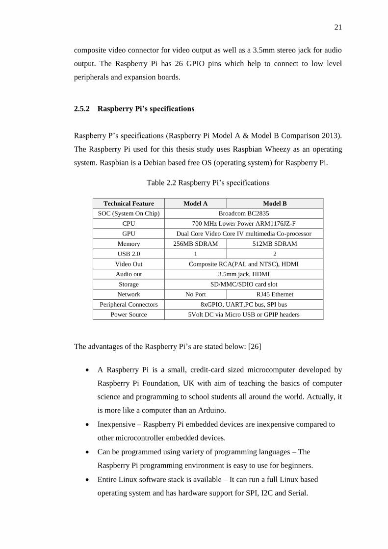
2.5.2 Raspberry Pi’s specifications
Raspberry P’s specifications (Raspberry Pi Model A & Model B Comparison 2013).
The Raspberry Pi used for this thesis study uses Raspbian Wheezy as an operating
system. Raspbian is a Debian based free OS (operating system) for Raspberry Pi.
Table 2.2 Raspberry Pi’s specifications
Technical Feature Model A Model B
SOC (System On Chip) Broadcom BC2835
CPU 700 MHz Lower Power ARM1176JZ-F
GPU Dual Core Video Core IV multimedia Co-processor
Memory 256MB SDRAM 512MB SDRAM
USB 2.0 1 2
Video Out Composite RCA(PAL and NTSC), HDMI
Audio out 3.5mm jack, HDMI
Storage SD/MMC/SDIO card slot
Network No Port RJ45 Ethernet
Peripheral Connectors 8xGPIO, UART,PC bus, SPI bus
Power Source 5Volt DC via Micro USB or GPIP headers
The advantages of the Raspberry Pi’s are stated below: [26]
A Raspberry Pi is a small, credit-card sized microcomputer developed by
Raspberry Pi Foundation, UK with aim of teaching the basics of computer
science and programming to school students all around the world. Actually, it
is more like a computer than an Arduino.
Inexpensive – Raspberry Pi embedded devices are inexpensive compared to
other microcontroller embedded devices.
Can be programmed using variety of programming languages – The
Raspberry Pi programming environment is easy to use for beginners.
Entire Linux software stack is available – It can run a full Linux based
operating system and has hardware support for SPI, I2C and Serial.

22
It is very easy to connect to internet
Open source – The Raspberry Pi software is published as open source tools,
so the user easy to get the information experienced programmers.
23
CHAPTER 3
METHODOLOGY
3.1 Introduction
This chapter will introduce about methodology of the doing this project has been
outlined so that the satisfied result will acquired. This methodology divide into FIVE
basic research, nonlinear load problem, One Cycle Current Controller (OCC) Design,
Gate Driver circuit design, current sensor design and Active Power Filter Design.
This project research diving into two task, which are simulation and hardware
analysis. For simulation analysis, whole simulations are using software called Matlab
/ Simulink and all the five basic research are constructed, simulated and verify the
result thru basic concept of One Cycle Current Controller. For the hardware
implementation, the model has been developing based on five basic research
prototypes due to apply the controller method and analysis the performance of each
part.

24
3.2 Block Diagram
Phase C
Phase B
Phase A
UNBALANCED LOAD
CURRENT
SENSOR
ONE-CYCLE
CURENT
CONTROLLER
GATE DRIVER
CIRCUIT
DC POWER
SUPPLY
3 PHASE
INVERTER
ACTIVE POWER FILTER
Figure 3. 1 Block diagram of the project
Figure 3.1 shows the block diagram of the whole project of development of One
Cycle Current Controller OCC using Raspberry Pi. This development of Active
Power Filter (APF) consists of FIVE main parts which are the DC power supply as
the input, gate driver circuit as an isolator circuit and PWM signal generator, three
phase inverter, and current sensor as a feedback input current to the controller and
One Cycle Current Controller (OCC). The power supply is generated by dropping the
voltage from 3 phases 415V to 3 phases 24V and connects it to the three phase
nonlinear load. For the load component consist of six power diode and power resistor
with the rating of load 10Ω, 50 W and the diode characteristic will interrupt the
fundamental waveform of current from supply and form “double hump” waveform to
the load.
The first part is an input which is the DC voltage that fed to a three phase
inverter and performs as Active Power Filter (APF). The gate drivers use a 5 Vdc
while the inverter input voltage depends on the loads that need to be powered.
Second part is the gate driver circuit which has a function that to double up the PWM
signal from the Raspberry Pi and also perform as isolator circuit. The gate driver will
71
REFERENCES
[1] N. A. Rahim Member, IEEE, S. Mekhilef, and Z. Islam. “A New Approach
for Harmonic Compensation Using Single- phase Shunt Active Power
Filter A New Approach for Harmonic Compensation Using Single- phase
Shunt Active Power Filter”. Institute of Research Management and
Consultancy, University of Malaya. April 30, 2005.
[2] H. Zhang, “Research and design of three-phase six-switch high power factor
rectifier with one cycle control,” 2009 IEEE 6th Int. Power Electron. Motion
Control Conf., vol. 3, pp. 1704–1707, May 2009.
[3] Raymond E. Beighley, Charles A. Gougler, James R. Johnson. “Application
of Active Harmonic Filters for Power Quality Improvement”. IEEE 519-
1992.
[4] H. M. Transformers and H. B. Filters, “MIRUS International Inc .,” 2010.
[5] H. R. Riverfront, S. Louis, S. Leng, W. Liu, I. Chung, and D. Cartes, “Active
Power Filter for Three-Phase Current Harmonic Cancellation and Reactive
Power Compensation,” pp. 2140–2147, 2009.
[6] Gyugyi L., Strycula E.C., “Active AC Power Filters”, IEEE IAS Annual
Meeting, pp.529, 1976.
[7] Mohan N.,Peterson H.A., Long W.F., “Active Filters For AC Harmonic
Suppression”, Proceeding of the IEEE-PES Winter Meeting, Paper A77026-
8,1977.
[8] Madhavi L. Mhaisgawali, Mrs S.P.Muley “Speed Control of Induction Motor
using PI and PID controller” IOSR Journal of Engineering (IOSRJEN), vol.3,
Issue 5 (May2013
[9] Algreer, Maher; Armstrong, Matthew; Giaouris, D., "Predictive PID controller
for DC-DC converters using an adaptive prediction error filter," Power
72
Electronics, Machines and Drives (PEMD 2012), 6th IET International
Conference on , vol., no., pp.1,6, 27-29 March 2012
[10] Robert D Henderson, Patrick J. Rose “Harmonics: The effect on power quality
and transformer” IEEE Trans. Industry Applications, vol. 30, no.3, (1994):pp.
528-532.
[11] Singh B., Haddad K. A., and Chandra A.,”A review of Active Power Filter
for power quality improvement”, IEEE Trans. Industrial Electronics, vol.46.
no.5, (1999):pp. 960-971.
[12] Peng F. Z., Akagi H., Nabae A., “A new approach to harmonic compensation
in power system- a combined system of shunt passive and series active filters
” IEEE Trans. Industry Applications, vol. 26, (1990):pp.983-990.
[13] Akagi H., Kanazawa Y., and Nabae A., “Instantaneous reactive power
compensators comprising switching devices without energy storage
components,” IEEE Trans. Ind. Applicat., vol. IA-20, (1984):pp. 625–630.
[14] Bhattacharya S. and Divan D., “Synchronous frame based controller
implementation for a hybrid series active filter system,” IEEE Conf. On
Industry applications, vol.4,(1995):pp. 2531–2540.National Institute of
Technology, Rourkela Page 64
[15] Lin C. E., Su W. F., Lu S. L, Chen C. L., and Huang C. L., “Operation
strategy of hybrid harmonic filter in demand-side system,” IEEE-IAS
Annul. Meeting, Industry applications, (1995):pp. 1862–1866.
[16] Dahono P.A, “New hysteresis current controller for single-phase bridge
inverters” IETjournal on Power electronics, vol.2 (2009):pp. 585-594.
[17] Hongyu Li., Fang Zhuo, Zhaoan Wang, Lei W. and Wu L., “A novel time
domain current detection algorithm for shunt Active Power Filter s” IEEE
Trans. power systems, vol.20,(2005):pp. 644–651.
[18] Buso S., Malesani L., Mattavelli P. and Veronese R., “Design and fully digital
control of parallel active filters for thyristor rectifier to comply with ICE
1000-3-2 standard” IEEE Trans.Ind. Applicat., vol. 34, (1998):pp. 508–517.
[19] B.O. Slim, Braha A. and Ben saoud s. “Hardware design and Implementation
of digital controller for Parallel Active Filters” IEEE Conf. Design and test of
integrated systems in nanoscale technology, (2006): pp. 331-334.
[20] Y.F.Chan, Moallem M., and Wei Wang “Design and implementation of
modular FPGAbased PID controllers” IEEE Trans. Indus. Elect. vol. 54,
(2007):pp. 1898-1906.
[21] Power Electronics: Circuits, Devices, and Applications. Pearson Education,
2004.

73
[24] Chongming Qiao and Keyue.M Smedley, "Three-Phase Active Power Filter
with Unified Constant-frequency Integration Control," in Proceedings of IEEE
In!. Conference on Power Electronics and Motion Control, PIEMC, vo!.2,
pp.698--70S, 2000.
[25] K. M. Smedley and S. Cuk, “One-cycle control of switching converters,”
IEEE Trans. Power Electron., vol. 10, no. 6, pp. 625–633, 1995.
[26] Fung Po Tso; White, D.R.; Jouet, S.; Singer, J.; Pezaros, D.P., "The Glasgow
Raspberry Pi Cloud: A Scale Model for Cloud Computing
Infrastructures," Distributed Computing Systems Workshops (ICDCSW), 2013
IEEE 33rd International Conference on , vol., no., pp.108,112, 8-11 July 2013
[27] A. A. Salam, N. Azran, and A. Hadi, “Fuzzy Logic Controller for Shunt
Active Power Filter,” pp. 256–259, 2014.
[28] L. Xinyang, W. Jie, Y. Gang, and A. T. Structure, “Application of Fuzzy
Control in Harmonic Detecting and Current Control of APF,” 2012.
[29] Jingwei Xu; Xin Feng; Mirafzal, B.; Demerdash, Nabeel A., "Application of
Optimal Fuzzy PID Controller Design: PI Control for Nonlinear Induction
Motor," Intelligent Control and Automation, 2006. WCICA 2006. The Sixth
World Congress on, vol.1, no., pp.3953, 3957, 0-0 0.
[30] P. Rathika, D. Devaraj. “Fuzzy Logic-Based Approach for Adaptive
Hysteresis Band and Dc Voltage Control in Shunt Active Filter”. International
Journal of Computer and Electrical Engineering , Vol. 2, No. 3, June, 2010.
[31] Zainal Salam, Tan Perng Cheng and Awang Jusoh. “Harmonics Mitigation
Using Active Power Filter: A Technological Review”, Elektrika, VOL. 8, NO.
2, 2006, 17‐26
[32] H. Doğan, R. Akkaya, “A Simple Control Scheme for Single-Phase Shunt
Active Power Filter with Fuzzy Logic Based DC Bus Voltage Controller,”
Proceedings of the International MultiConference of Engineers and Computer
Scientists 2009 Vol II IMECS 2009, Hong Kong, March 18 - 20, 2009