development of palm oil-based fly ash powder-binder … · 2013-07-18 · development of palm...
TRANSCRIPT
DEVELOPMENT OF PALM OIL-BASED FLY ASH
POWDER-BINDER SYSTEM FOR THREE-DIMENSIONAL PRINTING
NORHIDAYAH BINTI MOHD ZAIN
A thesis submitted in
fulfillment of the requirement for the award of the
Degree of Master of Mechanical Engineering
Faculty of Mechanical and Manufacturing Engineering
Universiti Tun Hussein Onn Malaysia
JUNE, 2010
v
ABSTRACT
Three-dimensional printing (3DP) is one of the techniques in rapid prototyping (RP)
technology which creates parts directly from graphical data computer and it is being
widely used in diverse areas. However, the cost of the 3DP material is high and
limited to a number of choices that can be used due to the restricted capabilities of
the existing binder. This research aims to investigate the potential of the new
powder-binder system for palm oil-based fly ash (POFA) for 3DP applications. The
newly proposed material is a type of powder-binder system containing POFA
powder, maltodextrin and polyvinyl alcohol (PVA) which was prepared thoroughly
by three different techniques; mechanical mixing, ball milling and solution blending
process. Certain mass percentage of POFA powder-binder system was successfully
fabricated as a product of the 3DP of which distilled water was used as the binding
material and followed by post-treatment with the Z Max solution in order to further
improve their mechanical properties. The experimental results show that, by using
solution blending process during material preparation of the POFA powder-binder
system is able to achieve good tensile strength and surface quality with mean values
of 6.65MPa and 12.05μm, respectively. However, the preparation of POFA powder-
binder system by using the mechanical mixing method show good flexural strength
results with mean value of 44.7MPa. Both results of mechanical properties are
allegedly due to the bimodal powder in the POFA powder-binder system which
contains various particle sizes. Further studies are required to improve the quality of
the product printed using the POFA powder-binder system particularly regarding of
the dimensional accuracy. This study believes that the POFA powder-binder system
has the potential to be used as an optional material for 3DP applications.

vi
ABSTRAK
Pencetak tiga dimensi (3DP) merupakan salah satu teknik yang terdapat dalam
teknologi pembuatan deras (RP) dimana produk dihasilkan adalah melalui data
grafik berkomputer dan teknologi ini telah digunakan secara meluas dalam pelbagai
sektor. Walaubagaimanapun, kos bahan mentah bagi 3DP adalah tinggi dan tidak
mempunyai banyak pilihan disebabkan oleh keupayaan bahan pengikat yang sedia
ada adalah terhad. Penyelidikan ini dijalankan bertujuan untuk mengkaji potensi
sistem serbuk-pengikat yang baru bagi palm-oil based-fly ash (POFA) untuk
digunakan sebagai bahan mentah dalam aplikasi 3DP. Bahan baru yang dicadangkan
ini adalah merupakan sistem serbuk-pengikat yang mengandungi serbuk POFA,
maltodextrin dan polyvinyl alcohol, dimana bahan-bahan ini disediakan melalui tiga
proses yang berlainan iaitu mechanical mixing, ball milling dan solution blending
processes. Beberapa peratusan campuran serbuk-pengikat telah berjaya dihasilkan
sebagai satu produk 3DP yang menggunakan air suling sebagai cecair pengikat dan
seterusnya diikuti oleh proses rawatan dengan menggunakan larutan Z Max bagi
penambahbaikan sifat mekanikal produk yang dihasilkan. Hasil ujikaji menunjukkan
bahawa dengan menggunakan proses solution blending adalah dicadangkan bagi
mencapai kekuatan tegangan dan kualiti permukaan yang baik dengan purata bacaan
masing-masing adalah 6.65MPa dan 12.05μm. Walaubagaimanapun, penyediaan
serbuk-pengikat POFA menggunakan proses mechanical mixing adalah disyorkan
untuk mencapai kekuatan lenturan yang lebih baik dengan purata bacaan 44.7MPa.
Kedua-dua keputusan sifat mekanikal ini dipercayai disebabkan oleh serbuk bimodal
yang terdapat dalam sistem serbuk-pengikat POFA yang mengandungi pelbagai saiz
zarah. Kajian lanjut perlu dilakukan bagi memperbaiki kualiti produk yang
dihasilkan melalui 3DP menggunakan sistem serbuk-pengikat POFA terutamanya
dalam ketepatan ukuran dimensi. Kajian ini berpendapat bahawa sistem serbuk-
pengikat POFA mempunyai potensi untuk digunakan sebagai bahan altenatif untuk
aplikasi dalam 3DP.
vii
TABLE OF CONTENTS
TITLE PAGE
TITLE
DECLARATION
DEDICATION
ACKNOWLEDGEMENT
ABSTRACT
TABLE OF CONTENTS
LIST OF TABLES
LIST OF FIGURES
LIST OF SYMBOLS AND ABBREVIATIONS
LIST OF APPENDICES
i
ii
iii
iv
v
vii
xi
xii
xv
xvii
CHAPTER 1
INTRODUCTION
1.1 Background of study
1.2 Statement of problem
1.3 Objectives of study
1.4 Scope of study
1.5 Significant of study
1.6 Expected results
1.7 Organization of thesis
1
1
2
3
4
4
4
5
viii
CHAPTER 2 LITERATURE REVIEW
2.1 Introduction
2.2 Overview of rapid prototyping technology
2.2.1 Rapid prototyping techniques
2.2.2 Rapid prototyping process
2.3 Three-dimensional printing (3DP)
2.3.1 3DP basic operation
2.3.2 3DP process parameters
2.3.3 3DP powder materials
2.3.4 3DP binder materials
2.4 Canon desktop printer
2.5 Palm oil-based fly ash (POFA)
2.6 Previous study on the development of new
material for 3DP
2.7 Summary of literature review
6
6
6
7
7
10
10
14
17
17
19
20
21
27
CHAPTER 3
METHODOLOGY
3.1 Introduction
3.2 Material used in this study
3.2.1 POFA
3.2.2 Maltodextrin
3.2.3 Polyvinyl Alcohol (PVA)
3.3 Material characteristics
3.3.1 Microscopy physical characteristics
3.3.2 Particle size distribution
3.4 Material preparation
3.4.1 Powder preparation
3.4.1.1 Pulverizing process
3.4.1.2 Sieving process
3.4.2 Optimization of material composition
3.4.3 Powder mixing techniques
3.4.3.1 Mechanical mixing process
3.4.3.2 Ball milling process
3.4.3.3 Solution blending process
29
29
31
31
32
33
34
34
36
37
37
38
39
39
41
41
41
43
ix
3.5 Experimental work on 3DP machine
3.5.1 Sample preparation
3.5.2 Sample infiltration
3.6 Sample testing and analysis
3.6.1 Mechanical properties
3.6.1.1 Tensile test
3.6.1.2 Flexural test
3.6.2 Dimensional accuracy
3.6.3 Surface roughness measurement
3.7 Summary
44
45
46
46
46
47
48
49
50
52
CHAPTER 4
RESULTS & DISCUSSION
4.1 Introduction
4.2 Material characteristics
4.2.1. Microscopy physical characteristics
4.2.2. Particle size distribution
4.3 Optimization of material composition
4.4 Powder mixing techniques
4.4.1. Mechanical mixing process
4.4.2. Ball milling process
4.4.3. Solution blending process
4.5 3DP characteristics
4.6 Mechanical properties
4.6.1 Tensile strength
4.6.2 Flexural strength
4.6.3 Fracture surface morphology
4.7 Dimensional accuracy
4.8 Surface quality
53
53
53
54
57
58
59
59
62
63
64
66
66
68
70
72
75

x
CHAPTER 5 CONCLUSIONS
5.1 Conclusion
5.2 Recommendation for future work
5.2.1 Determination of the optimum printing
parameters
5.2.2 Improve the material preparation
78
78
79
79
80
REFERENCES
81
APPENDICES 87
xi
LIST OF TABLES
2.1 The percentage weight chemical composition of 18
ZCorp binders
2.2 Influence of binder content on dimensional error, 23
strength and modulus
2.3 The control factors and levels recommended from 25
ZCorp Inc.
2.4 Summary of research on development new material 28
for 3DP process
3.1 Percentage of powder mixture 40
3.2 Material formulation with distilled water 43
4.1 Mean size of particle distribution for raw materials 57
4.2 Material formulation results 59
4.3 Tensile strength of all mixing methods 67
4.4 Flexural strength of all mixing methods 69
4.5 Data of dimensional error 72
4.6 Value of roughness (Ra) 75
xii
LIST OF FIGURES
2.1 (a) Surface are presented by triangles, 8
(b) Faceted stl file translated with coarse tolerance,
(c) File translated with fine tolerance
2.2 Five steps of rapid prototyping 9
2.3 Z310 3DP machine 11
2.4 Schematic diagram of Z310 3DP machine 11
2.5 The printing process 12
2.6 Comparing the strong and weak axis for print heads 13
2.7 3DP process parameters 14
2.8 Binder setting saturation value description 15
2.9 Definition of shell and core 16
2.10 Canon IP1880 printer 19
2.11 Thermal inkjet schematic diagram 20
2.12 Scaffolds (a) compressive stiffness and (b) initial 22
yield strength
2.13 Influence of (a) ratio of maltodextrin to water on 24
green strength (b) green strength on sintered strength
and (c) pre-coated particle size on green strength
2.14 Effect of different composition ZP102/ wood materials 27
at (a) maximum stress, (b) surface quality,
(c) dimensional accuracy and (d) SEM image of wood
powder at 150x magnification
3.1 Methodology flow chart 30
3.2 Photograph images of (a) A sight of POFA being 31
discarded from the Kluang Palm Oil Factory and
(b) POFA
3.3 Photograph image of maltodextrin 32
xiii
3.4 Photograph image of PVA 33
3.5 Schematic operation of SEM 35
3.6 Fison sputter coater 35
3.7 Schematic setup of particle size analyzer, Cilas1180 36
3.8 Photograph images of (a) Auto Mortar Grinder 38
(b) Pulverissete 6 machine (c) Pulverized POFA
(d) Pulverized PVA
3.9 Photograph image of Sieve-shaker machine 39
3.10 Modified Canon desktop printer IP1880 40
3.11 Labkorea, ball mill machine 42
3.12 (a) Ceramic beaker (b) Ceramic balls used in 42
ball milling
3.13 3DP setup for default setting 44
3.14 Photograph images of 3D components produced 45
for samples testing and analysis
3.15 Universal testing machine (AG-1, Shimadzu) 47
3.16 Tensile test sample 47
3.17 Tensile test experiment setup 48
3.18 Three-point bending test sample 48
3.19 Three-point bending test experiment setup 49
3.20 Mitutoyo digital calliper 50
3.21 Direction of x, y and z-axis 50
3.22 (a) Mitutoyo SJ-400 surface roughness test machine and 51
(b) Measurement placement
4.1 SEM images of raw materials at 100x of magnification 54
4.2 Element distribution map of raw materials for (a) POFA, 56
(b) maltodextrin and (c) PVA
4.3 Particle size distribution of POFA material 57
4.4 Samples of each formulation 58
4.5 SEM images of raw material prepared using 60
mechanical mixing process
4.6 Elements distribution map of raw material of 61
mechanical mixing process
xiv
4.7 SEM images of raw material prepared using ball 62
milling process
4.8 SEM images of raw material prepared using solution 64
blending process
4.9 Single samples printing 65
4.10 Slippage error in multiple samples printing 65
4.11 Stress-stroke graphs for tensile strength 66
4.12 Mean and SD values of tensile strength 67
4.13 Stress-stroke graphs for flexural strength 68
4.14 Mean and SD values of flexural strength 70
4.15 Image of fracture surface 70
4.16 SEM images of fracture surface of (a) mechanical 71
mixing process, (b) ball milling process, (c) solution
blending method and (d) ZP102 materials
4.17 Mean dimension for all specimen at (a) length 74
(b) width and (c) thickness
4.18 Mean roughness value (Ra) at (a) left, (b) middle and 76
(c) right side
4.19 SEM image of (a) mechanical mixing process 77
(b) ball milling process and (c) solution blending
process and (d) ZP102 materials

xv
LIST OF SYMBOLS AND ABBREVIATIONS
cm Centimeter
kg Kilogram
kV kiloVolts
mm Millimeter
μm Micrometer
% Percentage oC Degree Celcius
ASTM American Society for Testing and Materials
BSE Backscattered Electron
CAD Computer Aided Design
CIM Computer Integrated Manufacturing
CMM Coordinate Measurement Machine
CT Computerised Tomography
DM Desktop Manufacturing
EDX Energy Dispersive X-ray
2D Two Dimensional
3D Three Dimensional
3DP Three Dimensional Printing
FDM Fused Deposition Modeling
FFF Freeform Fabrication
IGES Initial Graphics Exchange Standard
Inc Incorporated
ISO International Organization for Standardization
IT International Tolerance
LM Layered Manufacturing

xvi
LOM Laminated Object Manufacturing
MIT Massachusetts Institute of Technology
MJM Multi Jet Modeling
PMMA Polymethyl Methacrylate
POFA Palm Oil-based Fly Ash
PVA Polyvinyl Alcohol
RT Rapid Tooling
RP Rapid Prototyping
SE Secondary Electrons
SEM Scanning Electron Microscope
SFF Solid Freeform Fabrication
SLA Stereolithography Apparatus
SLS Selective Laser Sintering
STL Stereolithography
Z Corp Z Corporation
xvii
LIST OF APPENDICES
APPENDIX TITLE PAGE
A Work progress for research project 87
B Particle measurement data 89
C Tensile strength profile 96
D Flexural strength profile 99
E Surface roughness profile 102
F Patent Application 105
CHAPTER I
INTRODUCTION
1.1 Background of study
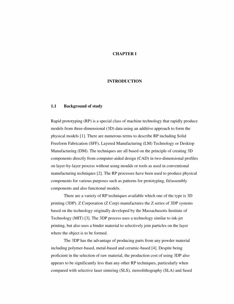
Rapid prototyping (RP) is a special class of machine technology that rapidly produce
models from three-dimensional (3D) data using an additive approach to form the
physical models [1]. There are numerous terms to describe RP including Solid
Freeform Fabrication (SFF), Layered Manufacturing (LM) Technology or Desktop
Manufacturing (DM). The techniques are all based on the principle of creating 3D
components directly from computer-aided design (CAD) in two-dimensional profiles
on layer-by-layer process without using moulds or tools as used in conventional
manufacturing techniques [2]. The RP processes have been used to produce physical
components for various purposes such as patterns for prototyping, fit/assembly
components and also functional models.
There are a variety of RP techniques available which one of the type is 3D
printing (3DP). Z Corporation (Z Corp) manufactures the Z series of 3DP systems
based on the technology originally developed by the Massachusetts Institute of
Technology (MIT) [3]. The 3DP process uses a technology similar to ink-jet
printing, but also uses a binder material to selectively join particles on the layer
where the object is to be formed.
The 3DP has the advantage of producing parts from any powder material
including polymer-based, metal-based and ceramic-based [4]. Despite being
proficient in the selection of raw material, the production cost of using 3DP also
appears to be significantly less than any other RP techniques, particularly when
compared with selective laser sintering (SLS), stereolithography (SLA) and fused
2��
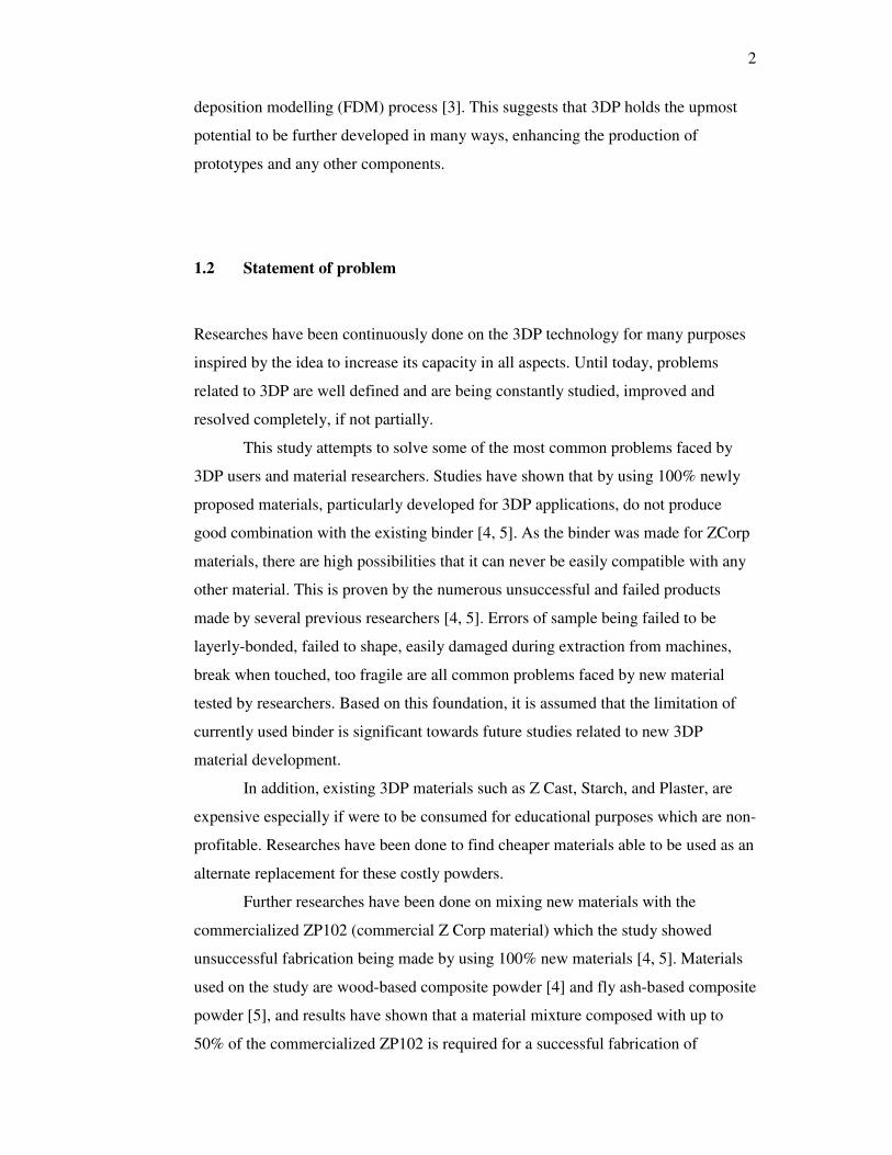
deposition modelling (FDM) process [3]. This suggests that 3DP holds the upmost
potential to be further developed in many ways, enhancing the production of
prototypes and any other components.
1.2 Statement of problem
Researches have been continuously done on the 3DP technology for many purposes
inspired by the idea to increase its capacity in all aspects. Until today, problems
related to 3DP are well defined and are being constantly studied, improved and
resolved completely, if not partially.
This study attempts to solve some of the most common problems faced by
3DP users and material researchers. Studies have shown that by using 100% newly
proposed materials, particularly developed for 3DP applications, do not produce
good combination with the existing binder [4, 5]. As the binder was made for ZCorp
materials, there are high possibilities that it can never be easily compatible with any
other material. This is proven by the numerous unsuccessful and failed products
made by several previous researchers [4, 5]. Errors of sample being failed to be
layerly-bonded, failed to shape, easily damaged during extraction from machines,
break when touched, too fragile are all common problems faced by new material
tested by researchers. Based on this foundation, it is assumed that the limitation of
currently used binder is significant towards future studies related to new 3DP
material development.
In addition, existing 3DP materials such as Z Cast, Starch, and Plaster, are
expensive especially if were to be consumed for educational purposes which are non-
profitable. Researches have been done to find cheaper materials able to be used as an
alternate replacement for these costly powders.
Further researches have been done on mixing new materials with the
commercialized ZP102 (commercial Z Corp material) which the study showed
unsuccessful fabrication being made by using 100% new materials [4, 5]. Materials
used on the study are wood-based composite powder [4] and fly ash-based composite
powder [5], and results have shown that a material mixture composed with up to
50% of the commercialized ZP102 is required for a successful fabrication of

3��
samples. It has been assumed that the cause of this requirement is because of the
usage of the original liquid binder, ZB56 which was made to suit the ZP102 in
particular. Therefore a study to find a suitable binder for this newly developed
material is needed to maximize cost reduction by fully eliminating the use of the
high cost ZP102. In this study, palm oil-based fly ash (POFA) is used as the raw
material since POFA has an encouragingly good prospect in terms of hardness,
surface quality and dimensional accuracy [5]. POFA is produced as waste products
by palm oil processing factories making it easily obtainable, unwanted and therefore,
currently, can always be acquired at no cost at all.
Furthermore, previous studies have shown that the polyvinyl alcohol (PVA)
and maltodextrin are able to form good binding ability with the parent material when
distilled water is added [6]. As it is easily available and cheap, it will be used for this
study to replace the original binder to further test its potential.
Therefore, this research is made as a platform to study the potential of the
new POFA powder-binder system for 3DP applications. As suggested above, since
the cost of the existing material is high and the choice of the material powder is
limited due to the restricted capabilities of the existing binder, this study was done to
further analyze the potential of POFA usage with the proposed PVA and
maltodextrin.
1.3 Objectives of study
The objectives of this research were focused on:
(i). to identify the characteristics of POFA and binder material.
(ii). to develop new material based on powder-binder system which can be used
as a raw material for 3DP process.
(iii). to analyze and compare the new material based on powder-binder system
with the existing material, ZP102 in terms of mechanical properties,
dimensional accuracy and surface quality.

4��
1.4 Scope of study
The scopes of this study were focused on:
(i) Materials studied were POFA, maltodextrin and PVA.
(ii) Distilled water was used as an optional binder for the existing binder.
(iii) Studies were made on dimensional accuracy and surface quality of the
sample.
(iv) Studies were made on mechanical properties of tensile strength, flexural
strength and structure morphology.
1.5 Significant of study
The significant of this research is to identify the potential of the new powder-binder
system in respect towards the binding ability of the new system itself with distilled
water for 3DP applications. This study will provide information and results on
mechanical properties of tensile strength, flexural strength, structure morphology,
dimensional accuracy and surface quality of the new material produced by the 3DP.
With this in order, hopefully it can be used to establish a ground on the new
material’s potential and capabilities and thus be further improved or identified to its
suitable application in the RP process.
1.6 Expected result
This research will reveal the knowledge on the potential of using the new powder-
binder system in 3DP applications. Comparison analysis can be successfully made
between the new material and the existing ZP102 material when their mechanical

5��
properties of tensile strength, flexural strength, dimensional accuracy and surface
quality are directly compared. Hopefully at the end of this research, good results can
be achieved and compared at its best quality in order to achieve the study objectives.
1.7 Organization of thesis
This thesis was organized into five chapters. Chapter one is the introduction to this
study which includes background of the study, objective, scope, and purpose of the
study. Chapter two is where the literature review and the case study of the related
works were discussed. Chapter three covers the experimental equipment and
procedures used in conducting the study. While, chapter four presents the results and
discussion of the study. Lastly, chapter five presents the conclusion and
recommendations for future work.

CHAPTER II
LITERATURE REVIEW
2.1 Introduction
Understanding previous researches are important because it can be made as a guide
to help this study move on. This chapter reviews the literature on existing RP
technologies, POFA and powder-binder materials. A basic RP operation and
processing technique are discussed herein. More detailed information on the 3DP
process was also presented, as the technique has been used in this research.
2.2 Overview of rapid prototyping technology
RP technology is a process of rapidly fabricating a model by using CAD data. RP
was largely used for clarifying Three-Dimensional (3D) CAD data during the
1980’s, but has been through a lot of evolutions since then [1]. This technology is
used to evaluate a design before expensive mass production takes place, also known
as the entry-level. The process of verifying and evaluating a successful design
contains several aspects which include: correct shape, correct size and adequate
strength [7]. These aspects are often referred to as form, fit and function. Form deals
with those aesthetics of the part that are essential to capturing the design’s intent. Fit
deals with the shape and dimensional accuracy of the part to ensure proper mating of
surfaces or features. Function is the ability of the part to be used and function as well
as a production part [8, 9].

7��
2.2.1 Rapid prototyping techniques
RP technologies are also often referred to as layered manufacturing technologies
[10]. The technique is also known by other names such as freeform fabrication
(FFF), solid freeform fabrication (SFF) and additive processes.
Generally, there are five most common RP technique that are commercially
available in the market [11] which are SLA, SLS, FDM, laminated object
manufacturing (LOM) and 3DP.
According to Kruth et al. [2], the RP process can be divided by the state of
the part material before part formation (type of raw material). It also can be
described by the building strategies [12, 13]; photopolymer, sintering,
gluing/lamination, and deposition (filament and inkjet). The basic operation of these
processes can be found from various publications including [14, 15, 16, 17].
2.2.2 Rapid prototyping process
Basically, the RP techniques are divided by the type of raw material including solid,
liquid and powder materials. Although several RP technologies exist, the systems
have same basic process which is the procedure can be divided into five steps [18].
(i) Create a CAD model of the design
First, a 3D representation of the part is created by a solid modelling computer
software package such as IDEAS, Unigraphics, ProEngineer, SolidWorks, etc. In
some cases, the 3D model can be created from 3D digitizer devices such as
coordinate measuring machine (CMM) and scanning devices such as 3D scanner or
computerised tomography (CT) scan. This allows the model to be created from a
physical object by collecting data from it’s original shape.

8��
(ii) Conversion to STL format
The second step is to convert the CAD file into STL format. This format represents a
3D surface as an assembly of planar triangles. The file contains the coordinates of
the vertices and the direction of the outward normal of each triangle [18]. The
various CAD packages use a number of different algorithms to represent solid
objects. To establish consistency, the STL (stereolithography) format, developed by
the Albert Consulting Group, has been adopted as the standard of the rapid
prototyping industry.
Because STL files use planar elements, they cannot represent curved surfaces
exactly. Often the STL file can be termed "bad" because of translation issues [19]. In
many CAD systems, the number of triangles that represent the model can be defined
by the user. If too many triangles are created, the STL file size can become
unmanageable. If too few triangles are created, curved areas are not properly
defined, as shown in Figure 2.1.
(a) (b) (c)
Figure 2.1: (a) Surface are presented by triangles, (b) Faceted stl file translated with
coarse tolerance, (c) File translated with fine tolerance [19]
(iii) Slicing STL file
In the third step, a pre-processing program prepares the STL file to be built. Several
programs are available, and most allow the user to adjust the size, location and
orientation of the model. The pre-processing software slices the STL model into a
number of layers from 0.1 mm to 0.25 mm thick, depending on the build technique.

�
The program m
during the build, depe
processing program i
Further review on slic
(iv) Layer-by-lay
The fourth step is the
The machines build o
needing little human
(v) Cleaning/ po
The final step is post-
and detaching any sup
materials need to be f
cleaning and surface t
Briefly, these steps ca
may also generate an auxiliary structure to su
ending on the requirements of the RP system.
s normally associated with a particular type o
cing procedures can be found from [20].
yer construction
actual construction of the part, using one of
one layer at a time, and most machines are fai
intervention.
st-processing
-processing. This involves removing the part
pports (applied only for certain processes). So
fully cured before use [12]. The part may also
treatment, depending on the specific fabricati
an be demonstrated by Figure 2.2 below:
Figure 2.2: Five steps of RP
Create a CAD model of the design
Conversion to STL format
Slicing STL file
Layer-by-layer construction
Cleaning/ post-processing
9�
upport the model
. The pre-
of RP machine.
several techniques.
irly autonomous,
from the machine
ome photosensitive
o require minor
ion process.

10��
2.3 Three-dimensional printing (3DP)
3DP is one of the RP process which falls under powder based categories [11]. The
3DP technology was developed at the MIT [14]. Z Corporation (Z Corp)
manufactures the Z series of 3DP systems, based upon technology originally
developed by the MIT [11]. These technology refers to a range of techniques
characterized by the method of delivering build material or build adhesive a series of
nozzle that are translated across the build platform. The basic build process is the
laying down of a layer of powder 0.1 to 0.25 mm of thickness. As the powder
supports the part, no support structure is required therefore allowing complex parts
to be built [21].
The ability of 3DP includes it’s potential in quickly produce a part and
evaluate it for form, fit and function which can reduce manufacturing lead time of
product up to 30-50% [20]. Yet, 3DP has limitations including size envelopes,
limited material properties, varying accuracies between x, y and z-axis and poor
surface finish [22]. These limitations are less significant when using 3DP to evaluate
a design particularly on form or aesthetics of a part. However it could be vital when
evaluating designs on fit and function or application for end-use products [23].
2.3.1 3DP basic operation
There are several models of 3DP machine available in the market such as Z310,
Z406 and Z810 which are manufactured by Z Corp. Basically, 3DP machine used
drop-on-demand jetting (thermal inkjet), which is one of an inkjet printing
technology [24].
The Z310 3DP machine as shown in Figure 2.3 is the entry-level concept
modelling solution that delivers great models quickly and inexpensively by using a
variety of materials. This model operates as mono device referring to single print-
head that can be used to print models with single colour [25]. Instead of feeding
paper under the print-heads like a 2D printer, a 3DP moves the print-heads over the
bed of powder upon which it prints the cross-sectional data from the CAD file which
has been slice into appropriate build layers.

11��
Figure 2.3: Z310 3DP machine [25]
Figure 2.4 shows the schematic diagram of Z310 3DP machine. The process
of model fabrication started with the addition of powder into the powder feed box.
Water based binder/resin is then poured into the resin reservoir to complete the
machine preparation for the model production run. Through the computer connected
to the machine, the CAD file is opened using the ZPRINT software. The software is
used to make final set-ups to the model before being printed by the machine. Using
the same software, the machine can be controlled and activated causing the printer to
build the model one layer at a time, gluing together the cross sections of the model
being built.
Figure 2.4: Schematic diagram of Z310 3DP machine [26]
Powder feed box
Print head
Powder overflow bin
Resin waste bottle
Resin Reservoir
Model tray

12��
Figure 2.5: The printing process [20]
Figure 2.5: The printing process [27]
Figure 2.5 explains the printing process of models. There are several
important characteristics of the 3DP system that help to print the best parts for
intended purpose which are [27]:
Step 1: As the gantry traverses left to right, the roller collects powder.
Step 2: The roller spreads a thin layer of powder over the build piston
Step 3: The roller discharges excess powder down the powder overflow chute
Step 4: As the gantry traverses right to left, the print head prints the part cross-section
Step 5: The feed piston moves up one layer, the build piston moves down one
layer, and the process is repeated
13��
(i). Part placement: The software automatically places the parts within the build
box to maximize build speed which is the most important criteria. The software
positions the parts with the smallest dimension in the Z (vertical) axis. In addition to
part placement, the following other characteristics should be considered.
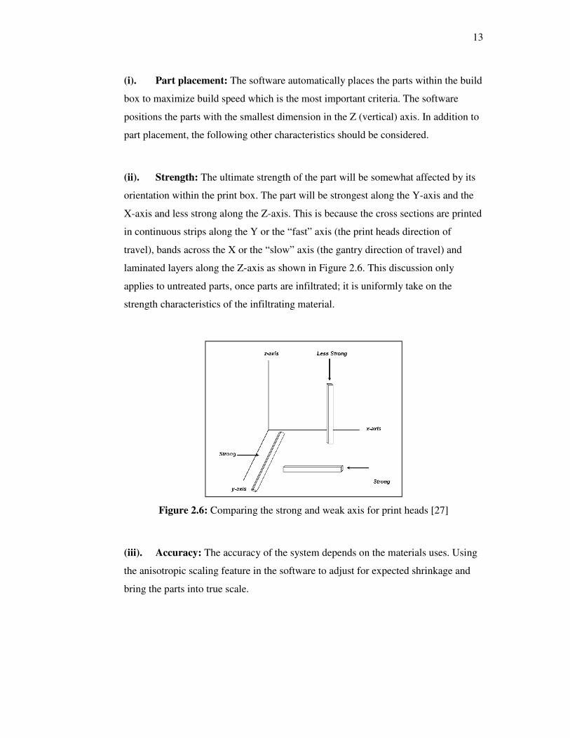
(ii). Strength: The ultimate strength of the part will be somewhat affected by its
orientation within the print box. The part will be strongest along the Y-axis and the
X-axis and less strong along the Z-axis. This is because the cross sections are printed
in continuous strips along the Y or the “fast” axis (the print heads direction of
travel), bands across the X or the “slow” axis (the gantry direction of travel) and
laminated layers along the Z-axis as shown in Figure 2.6. This discussion only
applies to untreated parts, once parts are infiltrated; it is uniformly take on the
strength characteristics of the infiltrating material.
Figure 2.6: Comparing the strong and weak axis for print heads [27]
(iii). Accuracy: The accuracy of the system depends on the materials uses. Using
the anisotropic scaling feature in the software to adjust for expected shrinkage and
bring the parts into true scale.

�
2.3.2 3DP process
The quality of buildin
its process parameter
& core), anisotropic s
prototyping machine
part and the build tim
prototypes with poor
manufacturing proces
2.7
Location omade-up par
parameters
ng parts and building performance of 3DP are
s including layer thickness, binder setting satu
scaling value, and location of made-up parts o
[27]. Each process parameter may affect the
me. Unsuitable process parameters setting may
quality and may waste materials and building
ss parameters of Z310 3DP system can be illu
Figure 2.7: 3DP process parameters
3DP Process Parameters
Binder setting saturation value
Layer
Anisotropic scalling value
f rts
14�
e strongly related to
uration value (shell
of the rapid
quality of a RP
y make RP
g time. The
ustrated as Figure
r thickness

15��
(i) Layer thickness: The layer thickness means the height of the powder bed
that dropped down along Z-axis in processing. It can be set within the range
of 0.0035” – 0.008”. The quality of the RP parts in terms of dimensional
accuracy may decrease as the number of layers increase.
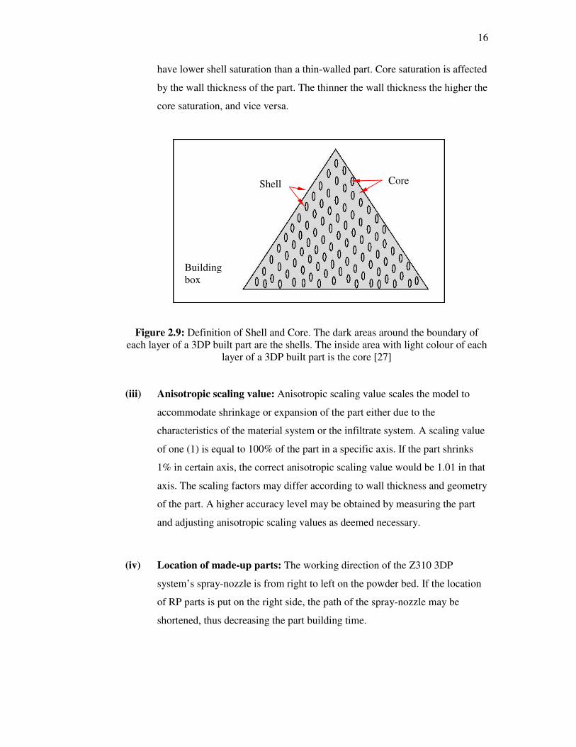
(ii) Binder setting saturation value (shell & core): The saturation values
(Figure 2.8) are referring to the determination of quantity of the binder placed
on the powder to print parts.
Figure 2.8: Binder setting saturation value description [27]
The building method of the Z310 3DP system uses a powder bound with
binder to shape RP parts. From 2D sectional layers that are sliced by slicing
algorithm system software, each 2D section is composed of shells and cores,
as shown in Figure 2.9. In general, the shell saturation is higher than the core
saturation. However, the saturation values are depended on the material used
in the 3DP process. For plaster material, the shell and core saturation values
are commonly consists of constant values, meaning that there is only one
value for all geometry types. While, the shell and core saturation values for
the starch material depends on the part geometry. A thick-walled part will
Binder setting saturation
value
16��
have lower shell saturation than a thin-walled part. Core saturation is affected
by the wall thickness of the part. The thinner the wall thickness the higher the
core saturation, and vice versa.
Figure 2.9: Definition of Shell and Core. The dark areas around the boundary of each layer of a 3DP built part are the shells. The inside area with light colour of each
layer of a 3DP built part is the core [27]
(iii) Anisotropic scaling value: Anisotropic scaling value scales the model to
accommodate shrinkage or expansion of the part either due to the
characteristics of the material system or the infiltrate system. A scaling value
of one (1) is equal to 100% of the part in a specific axis. If the part shrinks
1% in certain axis, the correct anisotropic scaling value would be 1.01 in that
axis. The scaling factors may differ according to wall thickness and geometry
of the part. A higher accuracy level may be obtained by measuring the part
and adjusting anisotropic scaling values as deemed necessary.
(iv) Location of made-up parts: The working direction of the Z310 3DP
system’s spray-nozzle is from right to left on the powder bed. If the location
of RP parts is put on the right side, the path of the spray-nozzle may be
shortened, thus decreasing the part building time.
Shell Core
Building box
17��
2.3.3 3DP powder materials
Materials used in 3DP machine are powder-based. Current offerings include two
cellulose (starch) materials (ZP14 and ZP15E) and a plaster material (ZP102) [27].
Without further processing, these materials lack the desired mechanical properties
for advanced application [24]. The particle size of the powder is in range 0.089mm-
0.203mm which is not more than the layer thickness of the machine [11].
In addition, the particle size of the powder influences the surface smoothness
and feature definition of the 3DP part. Fine powders have the potential advantages of
lower surface roughness, smaller minimum features, and thinner layers. Larger
particles are easier to spread, have lower surface area per volume and the larger
pores facilitate fluid migration through the bed to aid in the production of more
homogeneous parts [24]
Moreover, if the particles size becomes too fine (less than 10μm for
example), the static charges on the surface of the particles cause the powder to
become ‘fluffy’, and spreading the powder with the roller mechanism becomes
increasingly difficult [24, 28].
2.3.4 3DP binder materials
There are a number of different ways of binding the powder, but the common
selection criterion is based on the binder location which is in-liquid or in-bed. A
liquid binder contains all of the binding components in the printed liquid, but liquid
binders tend to have the occurrence of print-head nozzle clogs. An in-bed component
of a binder system is mixed with the powder and binding occurs where it interacts
with the deposited liquid.
Fundamentally, 3DP by ZCorp. uses the in-liquid type. These liquid binders are
different for each powder material of starch and plaster material. The properties of
the liquid binder are as shown in Table 2.1.

18��
Table 2.1: The percentage weight chemical composition of ZCorp binders [29]
Liquid binder for plaster material: ZB56 binder Chemical composition Approximate % by weight
Glycerol 1-10%
Preservative (Sorbic acid salt) 1-5%
Surfactant <1%
Salt <1%
Pigment 1-10%
Water 75-95%
Liquid binder for starch material: ZB51 binder Alcohol <1%
Fatty Acid Compound 0-20%
Humectant 0-20%
Preservative 0-1%
Surfactant 0-1%
Dye 0-1%
Pigment 0-1%
Water 75-98%
In the development of new binder for 3DP system, there are several binder
selections including organic binder, inorganic binder and metal salts [24]. Organic
binders are compatible with almost any powder material and can thermally
decomposed to leave small residue [24]. Possible organic binders include butyral
resins, polwmeric resins, and various polyvinyls. Other types of organic binder are
maltodextrin and sucrose which are usually used as in-bed binder.
A common selection of inorganic binder is colloidal silica due its variety of
uses and ease of manipulation [24]. When a stabilized colloidal silica solution (pH 9-
9.5) is printed into a powder bed containing acid or is exposed to gaseous CO2, the
pH drops and the colloid gels and the powder will bind together. Other inorganic
binder is aluminium nitrate where the method involves depositing solid material into
the bed by printing precursors or solid dispersion; the aluminium nitrate decomposes
into alumina and can be dissolved in deionized water. Solids can be deposited
directly in dispersions with oxides such as alumina which can be surface-treated to
form stable aqueous suspensions that are printable. The deposited solids may not act
as a binder immediately after deposition, but the entire bed can be heated after
printing to convert, melt or sinter the deposited material to bind the part within the

19��
bed before depowdering [24]. These types of binder are not commonly used in 3DP
machine because it requires gaseous exposure and a heater element to act as a binder.
Metal salts are binders that are particularly useful for metal powders which may be
utilized as both in-liquid and in-bed binders [24].
2.4 Canon desktop printers
Canon is one of the manufacturers in business and consumer imaging products
which includes computer printers, scanner, compact digital cameras, film and digital
SLR cameras, and lenses. Canon printing technology includes the development of
the bubble jet technology [30]. An example of Canon’s bubble jet technology printer
is IP1880 as shown in Figure 2.10.
Figure 2.10: Canon IP1880 printer [30]
Bubble jet, also known as thermal inkjet, is a drop-on-demand technology
that uses electrical pulses applied to heating elements in contact with the fluid near
the ejection aperture nozzle in order to vaporize a small amount of liquid to produce
pressure impulses by the formation and collapse of gas bubbles [31]. Essentially,
this technology is similar to the concept used for 3DP machine of which the 3DP

20��
machine was developed from the very basic concept of a conventional desktop
printer. Basically, the two forms in common use are classified by their fabrication
technology as roof shooters and edge shooters (Figure 2.11). Roof shooters are
fabricated by bonding an ejection orifice plate structure over the top of a wafer on
which the fluid flow and heating elements are fabricated. Edge shooters, in contrast,
form their ejection apertures from channel etched longitudinally into the wafer [31].
Figure 2.11: Thermal inkjet schematic diagram [31]
2.5 Palm oil-based fly ash (POFA)
In this study, POFA which is one of the biomass fly ash was chosen as a material to
make comparison with existing material for reducing the cost of material. Ashes can
be classified into two types which is bottom ash and fly ash. But, in this study it is
focusing on fly ash from palm oil. The term for “Biomass” is a material that derived
from living or recently living biological organisms, but in the energy context, it is
often used to refer to plant material, however by product and waste from livestock
forming, food processing and preparation and domestic organic waste that can be
formed as a source of biomass [32]. While for the term “Ash” is refer to the non-
combustible mineral content of biomass [32]. During combustion, bottom ash is the
ash that is left behind in or under the grate or combustion region, or at the bottom of

21��
a gasifier. “Fly Ash” consists of very small particles of ash that are carried out of
the system along with the flue gases. Various types of biomass produces ash that has
similar pozzolonic activity as coal fly ash, which include palm, rice husk, wheat
straw, sugar cane straw and wood [32].
With the growing general concern about the pollution by fly ash (FA), there
has been global interest in its utilization. Biomass Fly Ash is prohibits of ASTM
C618, precludes the use of any material not derived from coal combustion.
Typically, fly ash from neat biomass combustion has more alkali (Na and K) and less
alumina (Al2O3) than coal fly ash [33]. As a class, biomass fuels exhibit more
variation in both composition and amount of inorganic material than is typical of
coal. A purified fly ash (FA) containing 90% globular particle with a reasonable size
distribution is low in density, good shape with good dispersity and fluidity is suitable
as a polymer filling material [34].
POFA is heterogeneous fine powder consisting mostly of rounded or
spherical particles variable silica, alumina, and iron content. The major chemical
constituents of POFA are SiO2, Al2O3, Fe2O3 and CaO [35].
2.6 Previous study on the development of new material for 3DP
This section is to present previous studies done by other researchers on the
development new material of 3DP processing. Aimed to help making this research
successful, these studies were well considered throughout the development of the
project. There are numbers of studies reported in the literature related to
development of new material for 3DP.
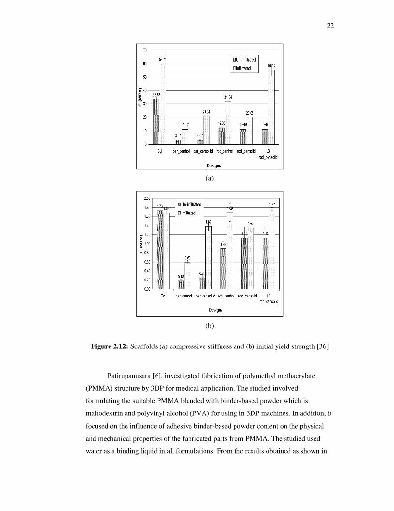
Lam et al. [36], studied scaffold development using 3DP with a blended
starch-based polymer. These scaffold development are referring to an artificial
structure capable of supporting three-dimensional tissue formation. The aim of the
research is to explore the feasibility of using 3D printing in combination with natural
polymers and water-based binders. From the result presented as in Figure 2.12, there
was a significant increase in the compressive stiffness and yield strength after
infiltration. This reinforced the theory that infiltration improved the mechanical
properties of the scaffolds.
22��
(a)
(b)
Figure 2.12: Scaffolds (a) compressive stiffness and (b) initial yield strength [36]
Patirupanusara [6], investigated fabrication of polymethyl methacrylate
(PMMA) structure by 3DP for medical application. The studied involved
formulating the suitable PMMA blended with binder-based powder which is
maltodextrin and polyvinyl alcohol (PVA) for using in 3DP machines. In addition, it
focused on the influence of adhesive binder-based powder content on the physical
and mechanical properties of the fabricated parts from PMMA. The studied used
water as a binding liquid in all formulations. From the results obtained as shown in
23��
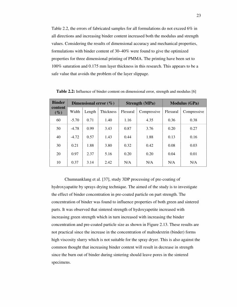
Table 2.2, the errors of fabricated samples for all formulations do not exceed 6% in
all directions and increasing binder content increased both the modulus and strength
values. Considering the results of dimensional accuracy and mechanical properties,
formulations with binder content of 30–40% were found to give the optimized
properties for three dimensional printing of PMMA. The printing have been set to
100% saturation and 0.175 mm layer thickness in this research. This appears to be a
safe value that avoids the problem of the layer slippage.
Table 2.2: Influence of binder content on dimensional error, strength and modulus [6]
Binder content
(%)
Dimensional error (%) Strength (MPa) Modulus (GPa)
Width Length Thickness Flexural Compressive Flexural Compressive
60 -5.70 0.71 1.40 1.16 4.35 0.36 0.38
50 -4.78 0.99 3.43 0.87 3.76 0.20 0.27
40 -4.72 0.57 1.43 0.44 1.88 0.13 0.16
30 0.21 1.88 3.80 0.32 0.42 0.08 0.03
20 0.97 2.37 5.16 0.20 0.20 0.04 0.01
10 0.37 3.14 2.42 N/A N/A N/A N/A
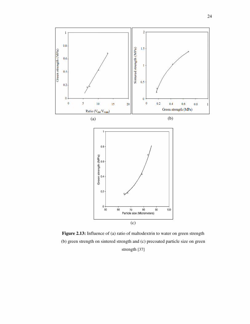
Chumnanklang et al. [37], study 3DP processing of pre-coating of
hydroxyapatite by sprays drying technique. The aimed of the study is to investigate
the effect of binder concentration in pre-coated particle on part strength. The
concentration of binder was found to influence properties of both green and sintered
parts. It was observed that sintered strength of hydoxyapetite increased with
increasing green strength which in turn increased with increasing the binder
concentration and pre-coated particle size as shown in Figure 2.13. These results are
not practical since the increase in the concentration of maltodextrin (binder) forms
high viscosity slurry which is not suitable for the spray dryer. This is also against the
common thought that increasing binder content will result in decrease in strength
since the burn out of binder during sintering should leave pores in the sintered
specimens.
24��
(b)
(c)
Figure 2.13: Influence of (a) ratio of maltodextrin to water on green strength
(b) green strength on sintered strength and (c) precoated particle size on green
strength [37]
(a)
REFERENCES
[1] Wohlers, T. (2004). Past, present and future of rapid prototyping.
International Journal of Product Development, 1(2), 147-154.
[2] Kruth, J. P., Leu, M. C., and Nakagawa, T. (1998). Progress in additive
manufacturing and rapid prototyping. CIRP Annals - Manufacturing
Technology, 47(2), 525-540.
[3] Grimm, T. (2004). “User’s guide to rapid prototyping”. USA.: SME.
[4] Wahab, M. S., Wagiman, A., and Zuki, N. M. (2009). Rapid prototyping of
wood-based material. Proceeding of the Conference on Malaysian Technical
Universities Conference on Engineering and Technology, pp. 31-35.
[5] Ibrahim, M., Saude, N., Ghafir, M.F.A., and Zain, N.M. (2009). Palm oil-
based fly ash for freeform fabrication of prototypes using 3D printers.
Proceedings of the International Symposium on Advanced Engineering,
Korea.
[6] Patirupanusara, P. (2006). Fabrication of polymethyl methacrylate structure
by 3DP for medical application. University of Mahidol, Thailand: Master’s
Thesis.
[7] Kietzman, J. (1999). Rapid prototyping polymer parts via shape deposition
manufacturing. Dissertation Abstracts International, 60 (4), 1815.
[8] Mackie, M. (2006). How are RP processes alike and how do they differ?
Time-compress (6), 7-9.

82��
[9] Raquet, J. (2005). An investigation into material properties and precision of
rapid prototyping technology. Dissertation Abstracts International, 66 (1),
513.
[10] Levy, G. N., Schindel, R., and Kruth, J. P. (2003). Rapid manufacturing and
rapid tooling with layer manufacturing (LM) technologies, state of the art
and future perspectives. CIRP Annals - Manufacturing Technology, 52(2),
589-609.
[11] Rafiq, N. (2006). Rapid Prototyping. USA. : John Wiley & Sons, Inc.2
[12] Beaman, Joseph J., Barlow, Joel W., Bourell, David L., Crawfordd, Richard
H.,Marcus, Harris., and McAlea, Kevin P. (1997) Solid freeform fabrication:
A new direction in manufacturing. Dordrecht, London: Kluwer Academic
Publishers.
[13] Beaman J. J., Atwood C., Bergman T. L., Bourell D., Hollister S., Rosen D.,
(2004). WTEC panel report on: Additive/Subtractive Manufacturing
Research and Development in Europe, World Technology Evaluation Centre
Inc Baltimore MD.
[14] Pham, D. T., and Gault, R. S. (1998). A comparison of rapid prototyping
technologies. International Journal of Machine Tools and Manufacture,
38(10-11), pp. 1257-1287.
[15] Chua, C.K., Chou, S.M. and Wong, T.S., (1998), A study of the state-of-the-
art rapid prototyping technologies, International Journal of Advanced
Manufacturing Technology, 14, pp. 146-152.
[16] Yan, X. and Gu, P., (1996), A review of rapid prototyping technologies and
systems, Computer-Aided Design, 28(4), pp. 307-318.
[17] Kulkarni, P., Marsan A. and Dutta, D., (2000), A Review of Process Planning
Techniques in Layered Manufacturing, Rapid Prototyping Journal, 6(1), pp.
18-35.
83��
[18] Pham, D. T., (2002). Learning factory rapid prototyping. Available from
www.me.psu.edu/lamancusa/rapidpro/primer/chapter2.htm. [Accessed
26/12/04].
[19] Kumar, V. and Dutta, D., (1997), An assessment of data formats for layered
manufacturing, Advances in Engineering Software, 28(3), pp. 151-164.
[20] Pandey, P.M., Reddy, N.V. and Dhande, S.G., (2003), Slicing procedures in
layered manufacturing: a review, Rapid Prototyping Journal, 9(5), pp. 274-
288
[21] Bocking, C.E. (2003), Rapid and Virtual prototyping and Applications. U.K:
Professional Engineering Publisher Limited.
[22] Huxley, M. and Weisberg, S. (2002). Rapid prototyping cuts time to market.
Cadalyst. Available from
http://www.cadalyst.com/cadalyst/articleDetail.jsp?id=97261 [Accessed
27/01/2007]
[23] Curtis, W. (2006). Additive prototype material properties: A well kept secret.
Time Compress Technologies, 11 (3). Available from
http://www.timecompress.com/magazine//archives.cfm [Accessed
27/01/2007]
[24] Utela, B. (2008). Development and Application of New Material Systems for
Three Dimensional Printing (3DP). University of Washington, USA: Ph. D.
Thesis.
[25] Z Corp. (2005). 3D Printer, Available from www.zcorp.com/ [Accessed
2/5/07].
[26] Ryan, V. (2006). Rapid Prototyping- The 3D Printer- Manufacturing
Sequence. Available from
http://www.technologystudent.com/cam/prn3d2.htm. [Accessed 23/07/2009]
[27] Z Corp. (2002). 3D Printer system user manual.
84��
[28] Nelson, J.C. (1993) Selective laser sintering: A definition of the process and
a empirical sintering model. University of Texas at Austin, USA: Ph. D.
Thesis.
[29] Z Corp. (2002). Material safety data sheet for ZB51 and ZB56 binder.
[30] Canon. (1981). Technology. Available from
http://www.bubblejet.canon.com.my/technolog/techno.htm [Accessed
23/05/2010].
[31] Lee, E. R. (2003). Microdrop generation. USA. : CRC Press LLC.
[32] Shuangzhen, W., Miller, A., Llamazos, E., Fonseca, F., and Baxter, L.
(2007). Biomass fly ash in concrete: Mixture Proportioning and Mechanical
Properties, Fuel, 8, pp. 365-371.
[33] Powell, P.C. (1999). Kejuruteraan dengan Polimer. Universiti Teknologi
Malaysia Skudai. 1-407.
[34] Yang, Yu-Fen. (2006). Surface modification of pulverized fly ash and
application in polymer. Fuel. 1-6.
[35] Osan, J., Alfoldy, B., Torokand, S., Grieken, R.V., (2002), Characterisation
of Wood Combustion particles Using Probe Microanalysis, 36, pp. 2207-
2214.
[36] Lam, C. X. F., Mo, X. M., Teoh, S. H. and Hutmacher, D. W. (2002).
Scaffold Development using 3D Printing with a Starch-based Polymer.
Material Science and Engineering, 20, pp. 49-56.
[37] Chumnanklang, R., Panyathanmaporn, T., Sitthiseripratip, K., and
Suwanprateeb, J. (2007). 3D printing of hydroxyapatite: Effect of binder
concentration in pre-coated particle on part strength, Journal Material,
Science and Engineering, 27, pp. 914-921.
[38] Rhodes, M. (2008). Introduction to Particle Technology. 2nd Ed. USA.: John
Wiley & Son, Ltd.
85��
[39] Carvalho, J.M., Gama, F.M., Hydrogels of Enzymatically Modified Dextrin.
Centro de Engenharia Biolagica, Universidade do Minho. Campus de
Gualtra, 4710-057 Braga, Portugal.p.1.
[40] Erickson A. Corn Strach. Con Refiners Asociation, Inc. 10th Edition: 2004;
14-15.
[41] Benton R. Determination of Maltodextrin in Pharmateceutical and Food
Products. Food and Beverage Methrom-Peak, Inc. The Application
Notebook. June 2004; 40.
[42] Hassan, C., Peppas, N. (2000). Structure and Applications of Poly (vinyl
alcohol) Hydrogels Produced by Conventional Crosslinking or by Freezing/
Thawing Methods, 153, pp. 37-62.
[43] Laurence, M., and Sharp, D.W.A. A New Dictionary of Chemistry, 4the
Edition. Wiley, New York. 1998.
[44] Finch, C.A. Poly (vinyl alcohol): Properties and Applications. Wiley, New
York.
[45] Scanning Electron Microscope (SEM), Available from
http://www.unl.edu/CMRAcfem/semoptic.htm [Accessed 01/01/10]
[46] Simon, G. P. (2003). Polymer characterization techniques and their
application to blends. Washington, D.C. American Chemical Society.
[47] Cilas 1180. (2000), Available from www.particle-size-
analyser.com/cilas_1180_particle.htm [Accessed 01/11/09].
[48] ISO 527 (1993) Plastic – Determination of tensile properties
[49] ISO 178 (2001) Plastic – Determination of flexural properties
[50] Lanzetta, M. and Sachs, E. (2003). Improved surface finish in 3D printing
using bimodal powder distribution. Rapid Prototyping Journal, 9 (3), pp. 157-
166.
86��
[51] Cooper, K. G. (2001). Rapid Prototyping Technology. USA, Marcel Dekker.
Inc.
[52] Dimitrov, D. and Wijck, W.V. (2006). Investigating the Achievable Accuracy
of Three Dimensional Printing. Rapid Prototyping Journal, 12, pp. 42-52.
[53] Pilipović, A., Raos, P., and Šercer, M.(2009). Experimental analysis of
properties of materials for rapid prototyping. International Journal
Advanced Manufacturing Technology, 40, pp. 105-115.
�