development of wall-pressed in-pipe robot...
TRANSCRIPT

DEVELOPMENT OF WALL-PRESSED IN-PIPE
ROBOT FOR CLEANING AND INSPECTION
TASKS
A THESIS SUBMITTED IN PARTIAL FULFILLMENT
OF THE REQUIREMENTS FOR THE DEGREE OF
Master of Technology
In
Industrial Design
By
Korra Dileep Kumar (Roll: 213ID1364)
Department of Industrial Design
National Institute of Technology
Rourkela-769008, Orissa, India
May 2015

DEVELOPMENT OF WALL-PRESSED IN-PIPE
ROBOT FOR CLEANING AND INSPECTION
TASKS
A THESIS SUBMITTED IN PARTIAL FULFILLMENT
OF THE REQUIREMENTS FOR THE DEGREE OF
Master of Technology
In
Industrial Design
By
Korra Dileep Kumar (213ID1364)
Under the supervision of
Prof. B.B.V.L. Deepak
Department of Industrial Design
National Institute of Technology
Rourkela-769008, Orissa, India
May 2015

Department of Industrial Design
NATIONAL INSTITUTE OF TECHNOLOGY, ROURKELA
ORISSA, INDIA – 769008
This is to certify that the thesis entitled “Development Of Wall-Pressed In-Pipe Robot For
Cleaning and Inspection tasks ”, being submitted by KORRA DILEEP KUMAR, Roll No.
213ID1364, to the National Institute of Technology, Rourkela for the award of the degree of
Master of Technology in Industrial Design, is a bona fide record of research work carried out
by him under my supervision and guidance.
The candidate has fulfilled all the prescribed requirements.
The thesis, which is based on candidate’s own work, has not been submitted elsewhere for the
award of a degree.
In my opinion, the thesis is of the standard required for the award of degree of Master of
Technology in Industrial Design.
To the best of my knowledge, he bears a good moral character and decent behavior.
Supervisor
Prof. (Dr).B.B.V.L. DEEPAK,
Assistant Professor, Department of Industrial Design
NATIONAL INSTITUTE OF TECHNOLOGY
Rourkela-769 008 (INDIA)
CERTIFICATE

i
ACKNOWLEDGEMENT
For each and every new activity in the world, the human being needs to learn or observe from
somewhere else. The capacity of learning is the gift of GOD. To increase the capacity of
learning and gaining the knowledge is the gift of GURU or Mentor. That is why we chanted
in Sanskrit “Guru Brahma Guru Vishnu Guru Devo Maheswara, Guru Sakshat Param
Brahma Tashmey Shree Guruve Namoh”. That means the Guru or Mentor is the path to your
destination.
The author first expresses his heartiest gratitude to his guide and supervisor Prof. (Dr.)
B.B.V.L Deepak, Assistant Professor of Industrial Design Department for his valuable and
enthusiastic guidance, help and encouragement during the course of the present research work.
The successful and timely completion of the research work is due to his constant inspiration
and extraordinary vision. The author fails to express his appreciation to him.
The author is thankful to Prof. (Dr.) Bibhuti Bhusan Biswal, Professor and Head of the
Department of Industrial Design and Prof. Mohammed Rajik Khan, Assistant Professor of
Industrial Design, NIT Rourkela, for their support during the research period.
The help and cooperation received from the author’s friend-circle, staff of the Department of
Training and Placement, staff of Department of Industrial Design is thankfully acknowledged.
Last but not the least, the author has been forever indebted to his parents' understanding and
moral support during the tenure of his research work.
Korra Dileep Kumar

ii
ABSTRACT
The aim of the project is to design a pipe cleaning and inspection robot for industrial
applications. This is going to use very simple mechanism for cleaning the internal area of the
pipe with changing diameters. The design is focusing on developing a bevel gear mechanism
which can able to clean and translate the robot body into the pipe effectively. Here we are going
to use only single DC motor for both cleaning and locomotion in the pipe. The inspection of
the pipe is by using the ultrasonic sensor. The ultrasonic sensor is going to give the distance
between the obstacle and the robot. According to the distance measured we are going to know
about the bends and joints. The ultrasonic sensor is also going to give information regarding
the waste materials accumulated in the pipe.

iii
TABLE OF CONTENTS
TITLE PAGE
ACKNOWLEDGEMENT…………………………………………………………. (i)
ABSTRACT…………………………………………………………………….. (ii)
TABLE OF CONTENTS………………………………………………………. (iii)
LIST OF FIGURES…………………………………………………………… (v)
LIST OF TABLES……………………………………………………………… (viii)
CHAPTER
1. INTRODUCTION…………………………………………………………. 1
1.1 Origin of work…………………………………………………………….. 2
1.2 Problem statement………………………………………………………… 2
1.3 Objective…………………………………………………………………… 2
1.4 Thesis overview……………………………………………………………. 3
2. LITERATURE REVIEW…………………………………………………. 4
2.1 Overview…………………………………………………………………… 4
2.2 Classification of in-pipe robots…………………………………………….. 4
2.3 Review on sensors used for in-pipe inspection…………………………….. 7
2.4 Review on Actuators used for motion control……………………………… 12
2.5 In-pipe robotic system and their architecture ……………………………… 14
2.6 In-pipe Cleaning techniques………………………………………………... 30
3 CONCEPT DEVELOPMENT ......................................................................... 35
3.1 Overview……………………………………………………………………. 35
3.2 Concept 1 primary model………………………………………………….... 36
3.3 Concept 2 final model ……………………………………………………… 39

iv
3.4 Summary…………………………………………………………………….. 41
4 DEVELOPMENT OF IN-PIPE ROBOT……………………………………. 42
4.1 Overview………………………………………………………………….... 42
4.2 Fabrication of prototype……………………………………………………. 42
4.3 Control circuit of in-pipe robot……………………………………………… 43
4.4 In-pipe inspection using ultrasonic sensor…………………………………… 46
4.5 Motion control of the in-pipe robot…………………………………………. 48
4.6 Actuation and control of cleaning task………………………………………. 49
4.7 Summary…………………………………………………………………….. 53
5 RESULTS & DISCUSSION………………………………………………... 54
5.1 overview…………………………………………………………………….. 54
5.2 In-pipe robot for Inspection and cleaning…………………………………… 54
5.3 discussion…………………………………………………………………….. 57
5.4 Summary……………………………………………………………………... 57
6 CONCLUSION AND FUTURE WORK …………………………………… 58
6.1 Conclusion …………………………………………………………………… 58
6.2 Future work…………………………………………………………………... 58
REFERENCE…………………………………………………………………… 59

v
LIST OF FIGURES
FIGURE PAGE
Fig 1 A typical wheeled type in-pipe robot 4
Fig. 2 A typical caterpillar type robot 5
Fig.3 A typical wall pressed type robot 5
Fig 4 A typical walking type robot 5
Fig.5A typical inchworm type robot 6
Fig.6 A typical PIG type robot 6
Fig.7 Representation of triangulation for measuring distance 7
Fig.8 Representation of Structured Lighting Approach for measuring distance 8
Fig.9 Time of flight ranger finder 8
Fig.10Working principle ultrasonic sensor 9
Fig.11Working principle magnetic sensor 9
Fig.12Working principle infrared sensor 10
Fig.13A typical vision 10
Fig. 14Working principle touch sensor 11
Fig.15Working principle of ruby laser 11
Fig.16 Electrical actuators (DC motor and servo motor) 13
Fig.17 A typical hydraulic actuator 13
Fig 18 Pneumatic Actuator 14
Fig.19 Autonomous sewer inspection robot with multi modules 15
Fig 20 laser NDT for detecting flaws in the pipe 15
Fig .21 Air conditioner duct inspection robot 16

vi
Fig.22 Sewer cleaning and inspection robot 16
Fig.23 Redundant painting manipulator 17
Fig 24 In-pipe inspection robot 19
Fig. 25Modelling of sewage pipe cleaning and inspection robot 20
Fig.26 Modified duct cleaning robot 20
Fig.27 Tracing and localization system for in-pipe robot 21
Fig 28 Pipe diameter adaptive mechanism 22
Fig 29 In-pipe robot with universal joints for better steering 22
Fig.30Sewage cleaning mobile manipulator 23
Fig.31 Auto adaptive in-pipe robot 24
Fig.32 Pipe cleaning robot for air conditioning system 24
Fig 33Simple design of in-pipe cleaning robot 25
Fig 34 Walking type In-Pipe Robot 26
Fig.35 Inch worm prototype robot 26
Fig.36Autonomous system for pipe line inspection 27
Fig.37Robot for inspection and obstacle avoidance 28
Fig.38 Structure diagram of inspection device 28
Fig. 39Measurement and friction dynamic characteristics of pipe inspection robot 29
Fig.40Water jet cleaning technique 30
Fig.41Brush type cleaning device 30
Fig 42 In-pipe cleaning robot 35
Fig 43 cleaning portion 35
Fig 44 piston- cylinder mechanism 45

vii
Fig 45 testing the prototype-1 46
Fig 46 winding problem in prototype 36
Fig 47 prototype testing 46
Fig 48 final in-pipe model 38
Fig 49 3D printer & fabricated model 41
Fig 50 Pipeline cleaning robot control circuit 42
Fig 51 interfacing of ultrasonic sensor with Arduino controller 45
Fig 52 showing distance measured on the LCD screen 46
Fig 53 motion control using the ultrasonic sensor 47
Fig 54 actuation part 48
Fig 55 transmission shaft developed & CATIA models 49
Fig 56 wheels for transmission fabricated and CATIA model 49
Fig 57 wheel support 50
Fig 58 main shaft CATIA & fabricated model 50
Fig 59 cleaning portion 51
Fig 60 testing of bevel gear mechanism 53
Fig 61 fully expanded robot in pipe 54
Fig 62 fully compressed robot in pipe 55
Fig 63 robot inside a pipe 55
Fig 64 Showing the body-cover of the robot. 55

viii
LIST OF TABLES
TITLE PAGE
Table 1 Sensors used by robots for performing inspection operation………………………12
Table 2 Reviews on various types of in-pipe robot architectures…………………………...32

1
1 INTRODUCTION
Pipes are one of the most important components that are being used for the transportation of
the raw materials in many industries. They are the integral part of oil and gas industries.
Pipelines are used to carry materials like water, crude oil, gases, petroleum and industrial
waste. Due to over usage the pipes will damage very less time. So we have to monitor the
pipes continuously and clean the pipes on a regular basis. But inspection and cleaning the
pipes is not an easy task it requires a lot of effort and time.
In olden days, large size pipes like drainages are cleaned manually by labors. Because of the
size of the pipes and shapes involved with them we can’t use men for all occasions.
Especially the industrial pipes vary in size from millimeters to meters and contain many types
of harmful substances inside the pipe. The shapes are also very complicated, and branches
like T-shape, Y-shape, increaser, decreaser and elbow are making the locomotion even more
difficult. Because of the harmful substances it is necessary to use devices that can do the
inspection and cleaning operations in the pipe.
Because of the above reasons the only option we left with is the robots. The robots can come
handy for pipeline inspection and cleaning. Now a day’s many researchers are working on the
development of in-pipe robots. There are many robots designed for inspection and cleaning
some of them are given below
1. Wheeled type
2. Caterpillar type
3. Wall-pressed type
4. Walking type
5. Inchworm type
6. Pig type (Pipe Inspection Gauges)

2
1.1 Origin of Work
In olden days pipes were cleaned using the human labors. The labor used to enter into the
pipe and he used to clean the pipe by putting lot of efforts and consuming much time.
Sometimes he even risks his life by entering into the pipe. Pipes used in industries contain
many types of chemicals and harmful substances. Because of harsh environment we can’t use
human labors in the pipes. Now-a-days the human labors are replaced by the in-pipe robots.
In industries the many types of in-pipe robots are being used for the purpose of cleaning and
inspection.
Cleaning is not an easy task to perform, it requires lot of efforts. Because of the shapes and
size variations in the pipes, a simple robot cannot fulfill all the requirements. Hence we need
to accommodate different techniques needed for cleaning the pipe in single robot. So many
researchers are studying about the best mechanism that is going to be used for pipe cleaning
and inspection. Because of these reasons we need to develop a better pipe cleaning and
inspection robot to save time, men and money.
1.2 Problem Statement
Pipe cleaning is very important for the proper transportation of raw materials from one place
to other in industries. But cleaning is not an easy task. Harmful substances which are
accumulated in the pipe make it very difficult for humans to work in the pipes. The changing
diameter of pipes from few millimeters to several meters also a major factor. To overcome
the size variation problem and to prevent human intervention in pipe cleaning an in-pipe
robot with suitable features has to be developed in this project.
1.3 Objective
1. The objective of the project is to design a pipe cleaning and inspection robot for industrial
applications.
2. To develop an in-pipe robot for pipes with changing diameters.
3. To develop a single mechanism for both locomotion and cleaning.
4. To implement low-cost inspection system with good accuracy.
5. To develop better cleaning device.

3
1.4 Thesis Overview
This dissertation is organized as follows
Chapter 2 provides the information regarding the work done so far in developing an in-pipe
robot for cleaning and inspection. It also contains literature review on in-pipe robots and
provides information about the existing models of in-pipe robot.
Chapter 3 devotes to concept development. It will give data about various components used
in the in-pipe robot. It is also going to give information about various stages in developing
the final model of in-pipe robot.
Chapter 4 deals with the development of in-pipe robot. It will provide information about
robot fabrication. Motion control and inspection of pipe using the in-pipe robot is also
discussed in this chapter.
Chapter 5 outlines the experimental results of the work. It is going to provide information
regarding the inspection and cleaning. It talks about the performance of the in-pipe robot in a
real environment.
Chapter 6 deals with the conclusion and future work.

4
2 LITERATURE REVIEW
2.1 Overview
Lot of work has been done on the pipe cleaning robot up to now. Many types of robots had
been invented. In this a lot of literature study is done to understand the mechanism of various
types of in-pipe robots. Literature work is also done on various sensors that are used for
inspection of in-pipe environment for detecting the flaws in the pipe.
2.2 Classification of In-Pipe Robots
Generally, in-pipe robots configured into the following six types:
i. Wheeled type
ii. Caterpillar type
iii. Wall-pressed type
iv. Walking type
v. Inchworm type
vi. PIG type(Pipe Inspection Gauges)
Wheeled type in-pipe robots are very simple in design. They will appear just like a regular
robot. They can only use for pipes with horizontal sections. The main problem with this type
of robots is that they can’t give enough support to the robot structure while the robot is in
motion inside the pipe line. Enough support can be provided to the body by maintaining more
wheel track [1]. Fig.1 represents a typical wheeled type in-pipe robot for inspection purpose.
Fig 1 A typical wheeled type in-pipe robot [1]
Caterpillar type in-pipe robots will provide more gripping nature to the interior of the as
compared to that of a standard wheeled type in-pipe robots. They are used in places where we
require large grip with the pipe walls. Moreover, these robots are suitable for varying
diameter pipes [1]. Fig.2 represents a typical caterpillar type in-pipe robot for inspection
purpose.

5
Fig. 2 A typical caterpillar type robot [1]
Wall pressed type of pipe cleaning and inspection robots were very useful for the locomotion
in the vertical pipes. This type of robot contains flexible links that can provide sufficient
amount of force which will help the body to move in vertical pipes without slipping [2]. Fig.3
represents a typical wall pressed type in-pipe robot for inspection & cleaning purpose.
Fig.3 A typical wall pressed type robot [2]
Walking type in-pipe robots are rarely used in the industries due to its mechanical
complexity. Its design is very sophisticated so it can’t be used in all the time unless the
situation demands [3].Fig.4 represents a typical walking type in-pipe robot for inspection &
cleaning purpose.
Fig 4 A typical walking type robot [3]

6
Inchworm type in-pipe robots are very rarely used for pipes with long distances. They are
preferred using the pipes with small diameters of range in millimetres. Fig.5 represents a
typical inchworm type in-pipe robot for inspection & cleaning purpose.
Fig.5A typical inchworm type robot [4]
PIG type in-pipe robots are very famous for inspecting pipes with large diameters. It is one of
the most commonly used pipe cleaning robot when there is a good amount of flow in the
pipeline. By making small changes like adding a propeller, the motion of the robot can be
controlled [38] as shown in Fig.6.
Fig.6 A typical PIG type robot [5]
This investigation has been focussed on the implemented methodologies on the categorised
in-pipe robots for performing in-pipe cleaning and inspection tasks. Moreover, this work has
been concentrated on review of various sensors used in robots to perform in-pipes inspection
operation for determining flaws/cracks, corrosion affected areas, blocks and coated paint
thickness. Various actuators like dc motors, servo motors, pneumatic operated and hydraulic
operated are discussed in this review analysis to control the motion of various mechanical
components of the robot.
This paper is organised as follows: Section-2 provides review on various in-pipe inspection
techniques using sensor fusion data. Section-3 addresses review on various actuators using to
control the motion of the robots. Section-4 deals with the review analysis on various in-pipe
robots mechanical structures. Section-5 concludes the paper.

7
2.3 Review on Sensors used for Inspection
There are several sensors are equipped to the robot for the inspection purpose. Inspection task
includes detection of corrosion, blocks, flaws, cracks, tracing, locating, etc. in the pipe. Some
of the sensors used for this purpose are:
a. Ultrasonic sensor
b. Magnetic sensor
c. Infrared sensor
d. Vision sensor(camera)
e. Tactile sensor
f. LASER (Light Amplification by Stimulated Emission of Radiation).
Most of the above mentioned sensors are range sensors and are used to measure the distance a
point to the objects. The several range sensing techniques are
Triangulation This is the simplest method for measuring range. The light is emitted from the
source to the object at an unknown distance ‘D’. The object reflects the light back to the
detector at an angle ‘β’ as shown in Fig.7. The distance between the source and the detector is
already known and it is B.
Therefore the unknown distance D = B * tan β (1)
Fig.7 Representation of triangulation for measuring distance
Structured Lighting Approach This method uses light for calculating the range. In this
method a light pattern is projected on to a set of objects as shown in Fig.8. Then according to
the distortion caused by objects, the range is calculated from Eq. (2).
D = λ tan β (2)
Where λ is the focal length of the lens
8
Fig.8 Representation of Structured Lighting Approach for measuring distance
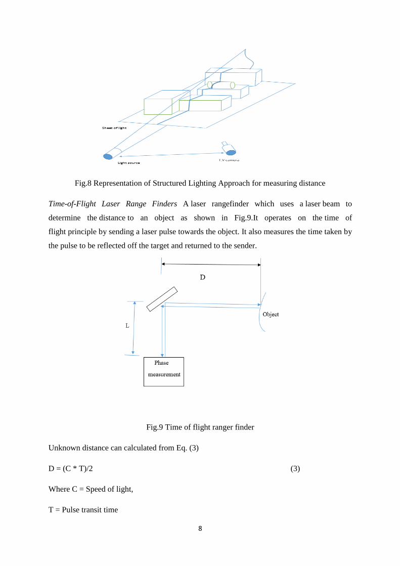
Time-of-Flight Laser Range Finders A laser rangefinder which uses a laser beam to
determine the distance to an object as shown in Fig.9.It operates on the time of
flight principle by sending a laser pulse towards the object. It also measures the time taken by
the pulse to be reflected off the target and returned to the sender.
Fig.9 Time of flight ranger finder
Unknown distance can calculated from Eq. (3)
D = (C * T)/2 (3)
Where C = Speed of light,
T = Pulse transit time

9
In-pipe inspection using ultrasonic sensor
Ultrasonic sensor is one of the commonly used sensors that is being used for the distance
measurement and can also be used for the inspection of the pipe. The sensor uses the
ultrasonic waves for finding the obstacles in the pipe. The working principle of a typical
ultrasonic sensor is represented in Fig.10. In order to inspect the in-pipe environment and
detect the flaws in the pipe, ultrasonic sensor has been used inpast research work [1],[6],[7],
[8], [9], [10], [11].
Fig.10Working principle ultrasonic sensor
In-pipe inspection using magnetic sensors
Magnetic sensors are commonly used to communication (between the user & robot) in the
pipe. These sensors reduce the shielding effect in the metallic pipes. Many experimental
results gave useful output in communication when magnetic sensors are used in the robot.
The working principle of a typical magnetic sensor is represented in Fig.11. A magnetic
sensor has been used by Choi et al. [9], Qi et al. [10] for tracing and locating the robot in the
underground pipes.
Fig.11Working principle magnetic sensor

10
In-pipe inspection using infrared sensors
Infrared sensors are just like the ultrasonic sensors. They use infrared waves for detecting
motion of robot inside the pipe on the basis of temperature. This kind of sensors can be used
for detecting the path of robot in the pipeline. The working principle of a typical infrared
sensor is represented in Fig.12. In order to inspect the inside area of the pipe infrared sensors
have been used in [8]
Fig.12Working principle infrared sensor
In-pipe inspection using vision sensors
Vision sensors (cameras) are very useful for performing inspection tasks in pipe lines. The
vision sensor is a charged coupled device. This sensor gives the most accurate information
about the interior of pipes. It is very useful for monitoring the pipe with the help of a display
device. In order to inspect the inside pipe environment [1], [7], [8], [11], [12], [13], [14],
[15], [16], [17], [18], visual sensor (camera) has been.
Fig.13A typical vision sensor [8]

11
In-pipe inspection using tactile sensors
Tactile sensors give information about the inside environment of the pipe by staying in
continuous contact with the pipe. This sensor can be very helpful in detecting the pipe
structure and roughness caused by the corrosion and wastes accumulated in the pipe. The
working principle of a typical tactile sensor is represented in Fig.11. There are different types
of touch sensors those uses principle of capacitance, inductance, resistance etc. In order to
detect paint thickness and flaws the pipe capacitive sensor has been used [2], [19].
Fig. 14Working principle touch sensor
In-pipe inspection using LASER sensors
LASER (Light Amplification by Stimulated Emission of Radiation) is an electronic device
that produces electromagnetic radiations. The working principle of a typical laser sensor is
represented in Fig.12. It produces light by the method of optical amplification. For the
purpose of inspection LASER has been used in [1], [8], [18].
Fig.15Working principle of ruby laser
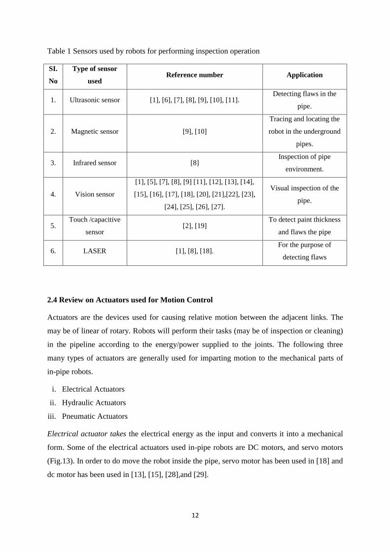
Table 1 illustrates the utilization of various sensors equipped to the in-pipe robots for
performing inspection task. The type of sensor used by the previous researchers for acquiring
the in-pipe information is tabulated below.
12
Table 1 Sensors used by robots for performing inspection operation
SI.
No
Type of sensor
used Reference number Application
1. Ultrasonic sensor [1], [6], [7], [8], [9], [10], [11]. Detecting flaws in the
pipe.
2. Magnetic sensor [9], [10]
Tracing and locating the
robot in the underground
pipes.
3. Infrared sensor [8] Inspection of pipe
environment.
4. Vision sensor
[1], [5], [7], [8], [9] [11], [12], [13], [14],
[15], [16], [17], [18], [20], [21],[22], [23],
[24], [25], [26], [27].
Visual inspection of the
pipe.
5. Touch /capacitive
sensor [2], [19]
To detect paint thickness
and flaws the pipe
6. LASER [1], [8], [18]. For the purpose of
detecting flaws
2.4 Review on Actuators used for Motion Control
Actuators are the devices used for causing relative motion between the adjacent links. The
may be of linear of rotary. Robots will perform their tasks (may be of inspection or cleaning)
in the pipeline according to the energy/power supplied to the joints. The following three
many types of actuators are generally used for imparting motion to the mechanical parts of
in-pipe robots.
i. Electrical Actuators
ii. Hydraulic Actuators
iii. Pneumatic Actuators
Electrical actuator takes the electrical energy as the input and converts it into a mechanical
form. Some of the electrical actuators used in-pipe robots are DC motors, and servo motors
(Fig.13). In order to do move the robot inside the pipe, servo motor has been used in [18] and
dc motor has been used in [13], [15], [28],and [29].

13
Fig.16 Electrical actuators (DC motor and servo motor)
Hydraulic actuators use fluids and hydraulic power to cause the motion in the system as
shown in Fig.14. The hydraulic actuators are very helpful in lifting heavy loads. It works with
piston and cylinder mechanism. For actuating the painting manipulator hydraulic actuator has
been used in [6].
Fig.17 A typical hydraulic actuator
Pneumatic actuator works on the principle of compressed air at high pressure as shown in
Fig.15. They are used to provide both linear and rotary motion. These actuators can produce
large force with fewer pressure changes. To actuate the devices pneumatic actuator has been
used in [21], [24], and [30].

14
Fig 18 Pneumatic Actuator
2.5 In-Pipe Robotic Systems and their Mechanical Architecture
Based on the mechanical architecture, in-pipe robotic systems have been classified into the
following six categories:
i). Wheeled type
ii). Caterpillar type
iii). Wall-pressed type
iv). Walking type
v). Inchworm type
vi). PIG type( Pipe Inspection Gauges)
Wheeled type in-pipe robots
Wheeled type in-pipe robots are very simple in design. They will appear just like a regular
robot. They can only be used for pipes with horizontal sections. The main problem with this
type of robots is that they can’t give enough support to the robot structure while the robot is
in motion inside the pipe line. Enough support can be provided to the body by maintaining
more wheel track.
Cordes et al.[12]developed an autonomous robot for operating in a sewage system. This robot
uses wheels for the locomotion. The body of the robot was divided into many modules for
better locomotion. Because of its structure as shown in Fig.16, the robot can carry large
number of devices which are helpful for doing certain tasks such as inspection, cleaning and
detecting flaws in the pipe. The developed in-pipe robot was able to move in the pipe
autonomously and can able take turns and move over the steps of heights of 300mm. The

15
control architecture of the hardware was very flexible and able to perform several tasks
intelligently. They used both the full force control and the kinematic control methodologies
for better sustainability.
Fig.19 Autonomous sewer inspection robot with multi modules [12]
Balaguer et al. [1] discussed the development of tunnel inspection with the help of robots.
The developed robotic system aimed to collect the data from the tunnel environment as
shown in Fig.17. The in-pipe robot can work in the environments of dark, toxic and very
dangerous for the human beings to inspect and collect the data. Their research work focussed
on surveying the environment of the tunnel by using the robots. They discussed various types
of robotic systems with devices like ultrasonic sensors, laser sensors, detecting cameras, 3-D
lasers for finding the cracks, etc. in the tunnel. All these robotic systems are employing
humans for assisting them. The studies finally come up to the conclusion, that to develop a
fully autonomous robotic inspection and survey system will be much helpful.
Fig 20 laser NDT for detecting flaws in the pipe [1]

16
Yusoff et al. [31] addressed the development of wireless inspection robot for air conditioner
ducts. The speed and motion of the robot were controlled by using the joystick. The robot
also helps in detecting the leaks by heat detecting technique using a temperature sensor and
cleans the duct of the air conditioner. The user is able to monitor the pipe with the help of
video captured by the camera. The robot used PIC16F877A and visual basic 6.0 for
interfacing with the computer. They used servo motors for the forward and backward motion
of the robot inside the pipe. Finally, they come to a conclusion that the robot was reducing
the number of human workers and can access the areas that can’t be reached by humans. The
complete structure and working principle of the developed robot is shown in Fig.18.
Fig .21 Air conditioner duct inspection robot developed by Yusoff et al. [31]
Elkmann et al. [18] developed a cleaning and inspection robot for sewer filled with water
partially. They used many kinds of sensors like ultrasonic scanner, laser ranging sensor and
camera as shown in Fig.19. The ultrasonic sensor used for detecting cracks and flaws in the
concrete structure. A camera used to gather information about the inside environment of the
pipe. The ultrasonic scanner was for detecting sewer gases and water spaces. The robot can
be used for concrete pipes with large diameters ranging from 1400 to 2800 mm. Deepak et al.
[42] discussed the type of wheels that can be used in the mobile robot. They gave information
about castor, Swedish, fixed standard, spherical type wheels. It also gave information of
degree of freedom of different types of wheels that can be used in mobile robot.

17
Fig.22 Sewer cleaning and inspection robot [18]
Chen et al. [6] presented a robotic system which was used for coating the S-shaped pipes. The
proposed robotic system was able to paint the inner area of the pipe without wasting the
paint. There are three components in the robotic system they are: 1) Chassis, 2) Positioning
base and 3) Painting manipulator. The chassis consists of wheels, hydraulic and gasbags as
shown in Fig.20. The robotic system was made to move in and out of the pipe system with
the help of wheels. The positioning base used for pointing the painting manipulator to the
desired location. The painting manipulator used to paint the interior of the pipe .To get the
information regarding the spray distance, they sued various sensors technologies are used.
The airless spray technology is for the distance between 30cm to 50cm. The air-assisted
airless technology is used for 25 to 30cm. The air spray technology is for distances ranging
between 15 to 25cm.
Fig.23 Redundant painting manipulator [6]

18
Saenz et al. [7] developed an in-pipe robot for performing inspection and cleaning tasks. The
robot is wheel driven and used for the pipes with diameter ranges from 1600 to 2600 mm.
The cleaning unit consists of a nozzle, with the help of it very high-pressure liquid is pumped
onto walls to remove the waste. The sensor system consists of various types of sensors like
ultrasonic scanners, multi-camera unit to determine the cracks, inclinometer for position
measurement, infiltration sensor and underwater camera system for underwater inspection
and crack detection purposes. La [28] invented a sewer cleaning apparatus. Here the frame
was displaced on the wheels and can be adjustable to the pipe. The toothed wheels are driven
by the motors and will give support to the body of the apparatus. The sharp toothed wheels
may cause damage to the pipe and it will cause problems while withdrawing the device
through the pipe. In case of the jamming, the propeller wheels help in moving without
touching the walls of pipe just like a torpedo or vessel. Lynch [32] invented the device for
gutter cleaning robot. This device contains a debris auger that will remove the debris. There
may be many types of augers like bristle, flap, twisting, plough type, etc. These can be
exchanged according to the use. They used fluids for cleaning the pipe. In this manner by
using the auger and the pressurized fluid the device can clean the pipe.
Atwood et al. [8] invented the device for inspection of the pipelines. The design of the robot
system is like a wheeled type. There are two portions of the body which are the track 1 and
track 2. They used various sensors inspecting the interior of pipelines. Langley et al. [19]
invented the pipe inspection robot. The pipe inspection was made possible with the
conductive brush and capacitive pads. When there is a change in the capacitance or
conductance, the flaws in the pipe can be identified. The conductive brush used in this system
is rotatable through an arc of 360. This developed system is mainly used for girth welds.
Langley et al. [30] gave information of a device was used for cleaning, inspection and coating
the pipeline. The device uses wireless grounding for all the components. The communication
between modules is by means of CAN bus which is a serial communication. The coating is
performed by means of fusion bonded epoxy and cleaning by vacuum.
Langley et al. [13] invented the device for pipe coating and inspection. The conductive
brushes and mil gauge are used for detecting the thickness of the coating. Cameras in the
front used for inspection and continuous feedback of visual data to the operator. The
controlling is wireless that is remote control. They used motorized wheels for moving the
robot. Huxiong [33] invented a swing-type pipe cleaning robot that comprises a rack, a
sweeping mechanism and a rotation driving mechanism. Sweeping mechanism is arranged on
the rack and includes a sweeping brush and a sweeping driving mechanism. Sweeping driving

19
mechanism is for driving the sweeping brush to rotate in the direction of the first axis.
According to the swing-type pipe cleaning robot, automatic large-breadth-swing cleaning and
clearing can be carried out on the interior of an air conditioner pipe. The swing-type pipe
cleaning robot has the advantages of being rapid in cleaning operation, convenient to use,
high in cleaning efficiency.
Liu [34] described a pipe cleaning device that uses a camera for inspection and wheels for
moving in and out of the pipe. There is a removable suction provided for cleaning the pipe.
There are two driving wheels for the travel. Tong et al [35] invented an air conditioning duct
cleaning robot. There are various units like the cleaning module, arms driving module,
walking driving modules, and control modules. There also provided a camera and lamp for
the inspection of the pipe. Chiu et al. [36] invented the pipe cleaning robot. This device is
mainly focused on how to change the directions quickly in a narrow pipe and how to drive
the mobile pipe cleaning robot into the pipe.
Caterpillar type in-pipe robots
The caterpillar type robots provide more gripping abilities than a standard wheel type. These
robots are used in places where we require large grip with the interior walls of the pipe. They
can also adjust the size according to the pipe diameter.
Kim et al. [15] designed a single-module fully autonomous mobile pipeline exploration robot
called FAMPER. It can be used for the inspection of 150mm pipe. It contains four caterpillar
based motion system as shown in Fig.21, for superior performance in all types of complex
networks of pipes. FAMPER also provides excellent mobility in vertical as well as horizontal
pipes. It is equipped with small and very powerful computing system various sensing and
actuating various components of the devices.

20
Fig 24 In-pipe inspection robot [15]
Truong-Thinh et al. [14] proposed an in-pipe inspection and cleaning robot. The robot mostly
used for the inspection of a pipe. The robot was able to move in the pipe with diameter 30 cm
to 40 cm. The locomotion of the robot in the pipe was performed with the help of toothed
wheels as shown in Fig. 22. The robot contains a cutting plate at the front part of the robot
that is used for removing waste accumulated in the pipe. They used CCD camera for the
inspection of the pipe.
Fig. 25Modelling of sewage pipe cleaning and inspection robot [14]
Meng et al. [20] discussed the experimental studies on motion and cleaning effect of a duct
cleaning robot. The developed robotic worked in efficient way in cleaning the ducts with
round shapes. After cleaning the duct a pre-run of 3-4 hours required. The experimental

21
results showed that the developed robot was inefficient in cleaning the ducts at elbows and
corners. Moreover, the robot failed in cleaning the bacteria near the rectangular ducts. All
these drawbacks were taken into consideration and some changes made in the robot design.
The modified robot is shown in Fig.22.
Fig.26 Modified duct cleaning robot [20]
Wall pressed type in-pipe robot
Wall pressed type of pipe cleaning and inspection robots were very useful for vertical pipes.
This type of robot contains flexible links that can provide sufficient amount of force which
will help the body to move in vertical pipes without slipping
Qi et al. [10] gave information regarding tracing and locating a pipe cleaning and inspection
robot for underground pipelines. They used a magnetic sensor and electromagnetic emitter
for tracing the robot. They simulated the entire setup to find the suitable coil for better
transmission of signals between outside and inside the pipe. Simulation results are useful to
refine the structure and thereby error between the magnetic dipole and emitting coil can be
reduced. Finally this gives a better design of coil structure. They also focused on tracking the
robot with an error of less than 20cm and 6-degree orientation. They overcome the shielding
effect by using the electromagnetic signals inside the pipeline.
Fig.27 Tracing and localization system for in-pipe robot [10]

22
Zhang et al. [16] developed in-pipe robotic system for performing inspection task. Their
primary concern was to develop the robot for underground pipes with changing diameters.
The robot is containing three sets of locomotion wheels which are at 120 degrees symmetric
to each other. They developed the models based on the adaptability to change according to
the pipe diameters. They come with a prototype that can able move in pipes with the diameter
ranging from 400-650mm. The designed prototype is also excellent at providing a sufficient
tractive force that is very necessary to anchor the device in the pipe. There are right amount
of tools that are helpful for visual inspection and some non- destructive testing tools are used
to monitor the blocks, cracks, corrosions, etc. inside the pipe. The experimental results
showed the robot can easily pass through slopes and Z-shaped joints. Moreover, the
developed system can be used for very long distance inspection beyond 1000 meters.
Fig 28 Pipe diameter adaptive mechanism [16]
Choi et al. [9] discussed about a mobile platform that was used for the inspection of pipes
with a diameter ranging from 160mm-240mm. The mobile platform is used for inspection
and Non-Destructive Testing (NDT) tasks in the pipe. The mobile platform is a snake-like
structure that uses a tether cable for communication and it consists of two active drive
systems one at the front and other at the rare portion of the system. Some other modules like
inspection, NDT module and control module are attached in between the two driving
modules. In this system, many features are facilitated like flexible leg mechanism for
adjusting to the diameters of the pipe and excellent steering system (Double Active Universal
Joint) which prevents the body to roll inside the pipe. All these facilities provide superb
mobility of the robot inside the pipe. They successfully used some non-destructive sensors
like the ultrasonic sensor and magnetic flux linkages. The major disadvantage of this in-pipe
robot is that, it is to be controlled manually at the branches for choosing the directions.

23
Fig 29 In-pipe robot with universal joints for better steering [9]
Nance et al. [37] invented the mechanism that will help in moving the pipeline robot in the
vertical direction. The system is consisting of grippers that help in holding the pipe very
efficiently. Ghorbel et al. [22] invented the in-pipe device in which there are various things
like turbine system, suspension system, pitched wheels and non-pitched wheels. It also
includes different sensors, various types of actuators and various types of communication
modules in the robot. The wheels are 120deg apart from each other and the size of the robot
is not more than 6 inches. There are two modules and an additional module can be attached to
it contains a fluid driven screw - drive propulsion system. Dhananchezhiyan et al. [29]
proposed a design of autonomous mobile manipulator. Here the mobile manipulator is used
for the sewage cleaning. Primary focus was given to the development of mobile manipulator
that is adaptable to the change in the pipe diameters to prevent the human intervention. The
model of the developed robotic system is shown in Fig.24. The developed robotic system is
driven with the help of motors. The high torque dc motor is providing the necessary power to
the end effecter for cleaning. The prototype was designed in solid works. The developed
model is tested for the pipes with a diameter of 0.03 to 0.05 meters and found adequate
cleaning was being performed by the robot.

24
Fig.30Sewage cleaning mobile manipulator [29]
Li et al. [2] presented a wall pressed type in-pipe robot for performing pipe cleaning and
inspection operations. The pipe cleaning robot is adaptive to change in size of the pipe
diameter. The range of the pipe diameter varies from 150mm to 450mm. The adaptive system
contains umbrella like open and close mechanism as shown in Fig.28. The robot includes
various types of devices like touch sensors for detecting the surface condition. The cleaning
brush is used for cleaning the pipe inner surface. The robot can be used for long length pipes
with varying diameters. They used ATmega64 controller for to achieve better motion
controlling of the robot.RS485 module used in order to make the robot work automate and
remote controlled in real time environment.
Fig.31 Auto adaptive in-pipe robot [2]
Ye et al. [38] proposed a robot used for air conditioner cleaning. The robot is movable with
the help of the wheels. The robot contains three parts they are 1. Front portion 2. Middle

25
portion 3.Back portion. The middle part is the driving unit with wheels and synchronization
mechanism for adjusting to the direction changes inside the pipe. The cleaning unit is placed
at the back portion of the robot. The robot is designed for both the horizontal and vertical
pipes as shown in Fig.29. They made the robot pass through branches, elbows and in the
vertical pipes with excellent precision.
Fig.32 Pipe cleaning robot for air conditioning system [38]
Bauer [17] discussed a device that is used to clean the inner pipe with a milling tool. The
milling tool is attached to the milling arm of the robot which is deflectable in only one plane
of the pipe. All the power cables and camera cables are passed through a pressurized chamber
of the milling robotic arm in a pressure tight way. Jung et al. [21] discussed the in pipe
inspection robot. The in-pipe inspection robot consists of 6 links that form a sliding
mechanism. All the links are adjustable to the pipe size. They used a pneumatic system to
change in the size instead of the springs. The operating range of the robot is from 300mm to
400mm pipes. They used the rotating brush for the cleaning the pipe. They did force analysis
in ANSYS Workbench.
Fig 33Simple design of in-pipe cleaning robot [21]
Kim et al. [39] discussed the robot for cleaning and has two units that are foldable at 180 deg
.the cleaning unit is mounted on the groove. This robot can’t perform cleaning when the robot
is at standing position. The wheels will prevent the robot from fall over by exerting suitable

26
force on the walls of the pipe. Zhou et al. [40] invented a device contains a simple module
with a cleaning unit is designed here. The cleaning unit consists of a brush rod that is attached
to the impeller. The gripper will provide necessary support while the cleaning is being
performed. There is an inbuilt generator that is providing power to the components.
Walking type in-pipe robot
Walking type robots are very rarely used in the industries due to its complexity. Its design is
very sophisticated so it can’t be used in all the time unless the situation demands.
Yang et al. [41] invented a robot for performing in-pipe inspection task. There are two
operating units with many arms which can be individually adjustable. The arm contains
slider-crank mechanism and an elastic unit that provides elastic pressure to the walls.
Landsberger et al. [3] presented a robot for pipe cleaning. It contains adjustable fins and
retraceable legs for anchoring the body. The generator used to provide power to electronic
equipment. Driven pulley and drive cable used to transfer materials. V-shaped legs are
provided for better grip at the curves and bends of the pipes. Cleaning is performed with a
high-pressure jet arrangement.
Huxiong [23] designed round pipe cleaning robot with an adjustable mechanism for the
change in the pipe. There is a monitoring unit, which consists of a camera of visualizing the
inside of the pipe. They also mentioned that the diameter of the cleaning device is slightly
greater than the diameter of the pipe for better cleaning.
Fig 34 Walking type In-Pipe Robot [41]

27
Inch worm type In-pipe robot
Inchworm type of robot is rarely used for performing in-pipe operations. These type of robots
are preferred for long pipes with small diameters range in millimetres.
Lim et al. [24] developed an inch-worm like pipe inspection micro robot that uses only
pneumatic actuation for its locomotion. In this robot there are three units as shown in
Fig.32.They are the front clamp, rear clamp and the elongated module. By varying the
pressurised air in different modules, they achieved inch-worm like motion inside the pipe.
The performance of the robot is dependent on the hole between the rear clamp and elongated
module. The speed of the robot depends on the cycle time of pressure that is being supplied.
The design is very simple and is able to fabricate this robot even for the pipes less than 10mm
in diameter. Here they achieved good adaptability to changing pipe sizes and velocity of
50mm/s in a pipe with 16 mm diameter by applying pressure of 2.0 bar and cycle time 0.6
sec.
Fig.35 Inch worm prototype robot [24]
PIG type in-pipe robot
PIG type is very famous one used for large pipe diameters. It is one of the most commonly
used pipe cleaning robot. These robots are used when there is a good amount of flow in the
pipeline. By making small changes like adding a propeller, the speed of the robot inside the
pipe can control. The PIGs are used for many functions like dewatering, inspection and
cleaning the pipe on a regular basis. The PIGs are the crucial tools for the contact testing in
gas and oil pipes.
Okamoto et al. [11] presented a PIG type in-pipe robot for inspection operations as shown in
Fig.33. They focused primarily on the inspection of interior of the pipe for detecting the
corrosion affected areas. They used various techniques like magnetic detection, ultrasonic
detection, visual inspection, eddy current detection, X-ray and acoustics, for performing

28
pipeline inspections. Initially inspection task has been done with the help of magnetic
method. But, they found it is not suitable for this task and came up with ultrasonic inspection
for detecting corrosion effected parts in the pipe caused due to the corrosive materials. They
used 16 ultrasonic sensors and got results very accurately even the area covered in mm2. They
are able to detect the corrosive parts with 10mm diameter and 1mm depth.
Fig.36Autonomous system for pipe line inspection [36]
Canavese et al. [5] discussed about the development of an automated pipe inspection device
called smart PIG. They mainly concentrated on the design of the device in such a way that it
has to pass through the pipe easily. The design is also aimed at cost reduction and making the
robot as a multi-functional. So that the device can detect, locate and can change its size
according to the pipe diameter. It has been given some additional features of sensing the
corrosion affected areas in the pipeline by detecting the pH or salinity of the material. The
additional sensors were making the device very powerful so that it gives the thickness of the
corrosion in the pipe. It also provided with special devices for data acquisition and storage.
Ramella et al. [25] was giving information regarding the smart foam PIG for pipe cleaning.
The primary focus has been given to the development of a low-cost pipe cleaning device. The
device is also so designed such that is going to face very less amount of obstacle avoidance
problem as shown in Fig.34. They used the ad-hoc software for data visualization and
interpretation. The developed prototype has been tested and the results were in good
agreement. The results were showing that the device gave very accurate data of the pipe and
is also very sensitive to small flaws and capable of large applications. Finally, its low-cost
and flexibility makes it a reliable device to use in the pipelines very often.

29
Fig.37Robot for inspection and obstacle avoidance [25]
Li et al. [26] developed a PIG type in-pipe robot as shown in Fig.35 for performing cleaning
and inspection operations. Here the probe dynamics tested for convex defects and
investigated using a home built inspection system. They concluded that the probe dynamics
changed with the uphill and the downhill sections and when the pipe is asymmetric. The
asymmetric behaviour is due the inspection device design. The experimental results proved
the speed and tightening elastic force were the main causes of the inspection precision loss.
Fig.38 Structure diagram of inspection device
Zhang et al.[27]discussed the Pipe Inspection Gauges (PIGs). Here the priority is given to
study the dynamic and frictional characteristics of the PIGs when it is passed through the
girth weld by the help of the custom built experimental setup. The complete analysis is shown
in Fig.36. The contact behaviour is studied between the girth weld and sealing disc using the
finite element analysis. The simulation results showing the sealing disc can be separated into
three stages 1 start-up stage 2 climbing stage 3 slop stage. In the stage 1 the PIG decelerates
and after that it accelerates. The reduction and increase of speed are causing the axial
vibration in the PIG.

30
Fig. 39Measurement and friction dynamic characteristics of pipe inspection robot [27]
2.6 In-Pipe Cleaning Techniques
Previous chapter addresses various inspection and cleaning techniques used for in-pipes.
There are various ways of cleaning the interior of the pipes. Among them most common
methods of pipe cleaning are:
Water jet technique.
Cleaning with help of some type brush.
Water jet technique
In water jet technique, the cleaning is performed by using pressurized water. The high-
pressurised water is passing through the nozzle hit the walls of the pipe.Fig.37 shows a
typical water jet technique for performing cleaning task in order to remove debris
accumulated on the pipe inner walls [7].
Fig.40Water jet cleaning technique [7]

31
Cleaning Brush Device
In brush type, cleaning is performed by using a cleaning brush. A cleaning brush/ rollers are
equipped to the in-pipe robot as separate module. This cleaning module is actuated by a high
torque DC motor [29] to performing cleaning operation.
Fig.41Brush type cleaning device [29]
Table 2 summarises the various types of in-pipe robot architectures, inspection and cleaning
task. Moreover, advantages and limitation of in-pipe robot architectures are mentioned

32
Table 2 Reviews on various types of in-pipe robot architectures
configuration Ref.
#
Inspection application
Type of
Cleaning Advantages Disadvantages
Flaws Corrosion Paint
thickness
Visual
inspection
Wheel type
[1] X X Brushes
The design of the
robot is very
simple.
The use of sensors
and cleaning
devices makes the
robot to inspect
and clean the pipe
in a better way.
The wheels may not be able to
give the sufficient friction to
move inside the pipe.
The wheels may dislocate its
position when cleaning operation
performing.
The robot cannot able to pass
through vertical pipes.
[6] X X X X
[7] X X High pressure
liquid
[8] X X X
[12] X X X
[13] X X X
[18] X X
[19] X X X
[28] X X X X X
[30] X X X Vacuum
[31] X X X Brushes
[32] X X X X High pressure
liquid
[33] X X X X Sweeping
[34] X X X Vacuum
[35] X X X Brush
[36] X X X X X
Caterpillar type
[14] X X X Cutting Plate The use of
caterpillar wheels
will give the robot
better grip to pass
through the
The design is complicated. [15] X X X X
[20] X X X X

33
vertical and
horizontal pipes.
Wall pressed
type
[2] X X X Brush The main
advantage of
the wall
pressed robot
is to give very
good grip
while climbing
the vertical
pipes, joints,
elbows etc.
It is used for
pipes with
varying
diameters.
There are some limitations like it
can work only for certain range
of pipe diameter.
[9] X X X
[10] X X X X
[16] X X
[17] X X X Vacuum
cleaner
[21] X X X Cleaning
portion
[22] X
[29] X X X X Brush
[37] X X X X Cleaning rod
[38] X X X X Brush
[39] X X X X Milling tool
[40] X X X X Brush
Walking type
[3] X X X X X They can also
travel in both
horizontal as well
as vertical pipes.
The use of V-
shaped legs makes
it to pass through
curves and bends
easily.
The motion is much
complicated. The leg has to
move in synchronized manner
for better locomotion.
[23] X X X X
[41] X X X X High
pressure jet
Inch worm type [24] X X X X
They are very good
in adaptability to
change in pipe
sizes.
The performance of the robot is
dependent on the hole between
the rear clamp and elongated
module.
PIG type
[5] X X Brush Low-cost and
flexibility makes it
a reliable device to
use in the pipe
lines very often.
We cannot use the PIG type
robot in vertical pipes.
They cannot provide much grip
in vertical pipes.
[11] X X X
[25] X X X
[26] X X X X
[27] X X X X

34
2.6 Summary
This section described the work performed on the in-pipe cleaning and inspection robot. This
study is on the mechanisms that were used for the pipe cleaning and inspection. Because of
various types and sizes of pipe, many researchers have developed various types of techniques
and methods for cleaning, inspection and locomotion. The literature study is on various
techniques that were used successfully in motion control of the robot. In this various inspection
methods are also discussed, that are going to be used for detection of flaws in pipe

35
3 CONCEPT DEVELOPMENT
Concept development is developing various types of concepts related to our work. After
developing various concepts, we have to select the best concept among them.
3.1 Overview
Concept development is a very important stage in building a product. This stage includes various
steps like
1. Research
2. Concept development and refining
3. Designing the computer model
4. Developing the prototype
5. Testing the prototype
The research stage is to study the various types of works that already performed on the related
field. From this research we are going to understand the existing models and what has to be
done.
When we are clear with the concept the next step is to design a computer model using CAD
tools. It includes phases like material selection and analysis.
Developing a prototype is the very important stage. One can develop prototype using techniques
like machining or 3D printing.
Testing the prototype in real environment is very important because we have to make sure the
product is working properly.
This chapter will give information regarding the developed concepts and steps followed in
achieving the final concept.

36
3.2 Concept 1-Primary Model
Many concepts have been developed but the first idea is to design an in-pipe robot which can
perform cleaning with help of three dc motors and locomotion by using a two high torque dc
motors. For automatic adjusting to pipe size we planned to use a piston cylinder mechanism. To
inspect the in-pipe environment we planned to use a camera at the front portion of the in-pipe
cleaning robot.
Fig 42 In-pipe cleaning robot
Fig 43 cleaning portion Fig 44 piston- cylinder mechanism

37
Fig 45 testing the prototype-1
Fig 46 winding problem in prototype Fig 47 prototype testing
The above figures 45,46&47 showing prototype testing. It is also giving information about the
defects in the design which are mention in the following points.

38
The designed model has many drawbacks like
1. Complex design
2. Single module
3. Too many electronic devices
4. Piston cylinder mechanism
5. Drag due to cleaning portion
6. Direction changes
Complex design
The above model is very complex in structure. Due to the complex structure the motors may not
provide sufficient torque to the body to move forward and backward.
Single module
There are no separate modules for cleaning and locomotion. This is one of the major drawbacks
in the model. Because of the single module while the cleaning is being performed there are
chances in the power cables to get detached from the robot. Since my design is a wired one.
Many electronic devices
Many electronic devices are there in the robot. They are control circuit, DC motors and camera.
As we know there are many types of corrosive substances in the pipe that is going to damage the
electronic components.
Piston and cylinder mechanism
The piston and cylinder mechanism used for automatic adjustment to pipe size. The mechanism
may not work properly because of the compressed gas used in it. The structure is also can’t
provide enough strength.
Drag caused by cleaning portion
Since the cleaning wheels are in the same axis to the pipe diameter, while cleaning they can do
better cleaning. Coming to the locomotion of the robot in the pipe the cleaning wheels are going

39
to cause lot of drag to the robot. Because of it the robot may require high amount of torque to
move in and out.
Direction change
There are many types of joints like T-joint, Y-joint, etc. and shapes like elbows in a pipe
structure. Because we used a single module there is no such mechanism for direction changing
which is very crucial in the pipe.
3.3 Concept 2-Final Model
This is the finally developed concept. In this the model is developed in such a way that it
overcomes all most each and aspect of the previous design. The design is focused to use only one
DC motor for both transmission and cleaning. There is a mechanism which uses a bevel gear to
provide both locomotion and cleaning simultaneously. The piston cylinder mechanism is also
used here but in a different manner.
Fig 48 final in-pipe model
The above figure is the refined model of in-pipe cleaning robot. This model has the following
advantages compared to the previous design.

40
Separate modules
The first and foremost advantage of this design is, here there are two separate modules for
transmissions and cleaning. They are so called body and the cleaning portion. In the body
module there will be high torque DC motor. By using the motor we can give power to the wheels
and cleaning portion. Because of these two separate modules the body portion will provide
enough anchoring point to the whole robot. There won’t be any problem regarding the power
supply cables because the body will not rotate while cleaning.
Electronic devices
We are using only one DC motor instead of 5 DC motors. This is saving a lot of space and
money. Since the space is very limited in the pipe the new design is much beneficiary.
Shielding
We provided shielding to the motor in the body cover so there won’t be problem regarding
corrosion. The wet conditions in the pipe can’t damage the motor.
Single mechanism for cleaning and moving
We used single mechanism for both cleaning and moving. The bevel gear mechanism is
performing both cleaning and moving operations.
Drag problem
There is very less amount of drag caused by the cleaning portion. Instead of circular cleaning
surface we used wipers. There is line contact in the wipers where as the contact is surface type in
a circular brush.
Piston-cylinder mechanism
Piston-cylinder mechanism consists of springs instead of compressed gas. Because we used
springs in the piston cylinder mechanism, there will better compression and expansion to the
changes in the pipe size.

41
Inspection module
In place of a camera we are using the ultrasonic sensor for inspection. The ultrasonic sensor is
comparatively cheap and it will give better inspection among all the sensors.
Universal joint
Direction change is very important in the pipes. The pipe will have various bends and joints for
all this we need some mechanism in the robot. So for direction changes we can use a universal
joint between the body and the cleaning portion. The universal joint is going to adjust to the pipe
bends and provide very good locomotion.
3.4 Summary
This chapter is focused on the concept development. There are two concepts discussed in this
chapter. The first concept is having some problems like the design, complexity, dragging, many
electronic devices, lacking direction changing mechanism, cost, piston-cylinder mechanism, and
power supply problem. To overcome the problems, the new model is focused on reducing the
problems and various types of mechanisms have been included in the robot.
The new model contains two modules for cleaning and moving. The cleaning portion has less
friction wipers. There is a universal joint in between the body and cleaning portion so that there
will be automatic direction change in the robot. The robot will move according to the direction of
the pipe.
In the new design a low-cost inspection system has been included for detecting the flaws. The
new model contains only one DC motor for both locomotion and cleaning. The piston cylinder
mechanism has spring in it for automatic adjustment to the pipe diameter.

42
4 EXPERIMENTAL ANALYSIS OF IN-PIPE ROBOT
4.1 Overview
Development of in pipe robot has been divided into several parts, they are
1. Computer aided design
2. Analyzing the design
3. Fabrication of prototype
4. Testing the prototype
Here we are going to discuss the prototype development. How it is made and controlled using the
latest controllers are going to be discussed in this chapter.
4.2 Fabrication of Prototype
After the CATIA model is ready, the CATIA file is exported to the 3D printer. The printer is
going to generate the 3D model of the design.
Fig 49 3D printer & fabricated model

43
4.3 Control Circuit of In-Pipe Robot
Fig 50 Pipeline cleaning robot control circuit
Figure 8 is showing the control circuit used for the in-pipe robot. The control is very simple and
easy to operate. Even person with little knowledge in electronics can easily control the in-pipe
robot. The control circuit has various components like
1. Controller
2. Ultrasonic sensor
3. DC motor
4. Motor driver
5. Potentiometer
6. Power supply
7. Switches
Power supply
Controller
Motor
Driver
Switch 1
Motor for
both
locomotion
and cleaning Switch 2
P1
Ultrasonic sensor

44
Controller
Controller is the major component in any control circuit. It is like brain of the body. The main
concern in design is to provide a very simple controller. There are many types of controllers in
the market but according to our need it should be compatible to all the components. When we are
going to write the code for controlling the robot, it supposed to be easy. Hence we decided to use
the arduino mega 2560 controller for the in-pipe robot.
The control is very is to handle. There are predefined slots for power supply, PWM, etc. so it will
be very easy for us to make connection with the remaining components. The size of the
controller is also very small and it can easily accommodate large number of devices. Coming to
the coding part, it is open source to everyone. One can go through the site and can get the code.
What we have to do is to make modification in the code according to our needs.
Ultrasonic sensor
The ultrasonic sensor is a simple device that is generally used for distance measurement. The
working principle of the ultrasonic sensor is just like a bat. There are two portions in an
ultrasonic sensor 1 trigger 2 echo. The trigger portion will emit the ultrasonic waves. When the
ultrasonic waves hit some object in front of it, it will be reflected back to sensor.
The echo portion is going to receive the reflected ultrasonic waves. The time gap between the
trigger signal and received signal is calculated and according that the distance between the sensor
and obstacle is measured. The same principle has been used here to detect the obstacles in the
pipe.
The main reason behind using the ultrasonic sensor in this in-pipe robot is the cost of the device
is very less. The sensor is also very accurate compared to other devices.
DC motor
The motor is one of the major components in the control circuit. It is used to provide both
transmission and cleaning. For performing the tasks it has to provide high amount torque. Since
we require very high torque there is need to use a geared motor with low RPM. For this we are

45
using a 300 RPM geared motor. The motor is tested and is giving very good amount of torque. It
can able provide cleaning and transmission.
Motor driver
Motor driver play a prominent role in controlling the DC motor. The motor driver helps in
changing the direction of rotation of the DC motor. The driver is going to receive the signals
from controller. According to control signal the driver is going to change direction of rotation.
There will be H-Bridge in the motor driver which is making the task possible.
The working principle of the H-bridge is very simple. The construction is showed below. The
direction of rotation of the motor depends on the flow of current in the motor. The motor driver
is the main component that changes the flow of current according to the control signal.
Potentiometer
Speed is another important parameter in the in-pipe robot. The speed has to be controlled in
order to achieve better cleaning and locomotion. It depends on the speed of rotation of the DC
motor. So we have to control the speed of the motor in order to control the speed of robot
transmission and cleaning. To control the speed we are using the potentiometer in our control
circuit. The potentiometer is going to vary the resistance in the circuit. When there is change in
resistance, according to that the amount of voltage or current changes. Depending upon the
amount of current flow in the motor the speed of rotation will vary.
Power supply
Power supply is very important for electronic devices to function. In this all the components are
of electronic background. So we are using the 5 volts DC power supply to all the components
except the motor. The motor ratings are different compared to the other devices in the circuit.
The motor requires 12 volts DC supply.
Switches
The switches S1 and S2 are used to give control signal to the robot. By using the switches we can
make the robot to move in and out.
46
4.4 In-Pipe Inspection Using the Ultrasonic Sensor
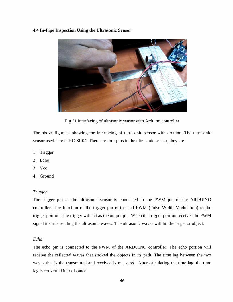
Fig 51 interfacing of ultrasonic sensor with Arduino controller
The above figure is showing the interfacing of ultrasonic sensor with arduino. The ultrasonic
sensor used here is HC-SR04. There are four pins in the ultrasonic sensor, they are
1. Trigger
2. Echo
3. Vcc
4. Ground
Trigger
The trigger pin of the ultrasonic sensor is connected to the PWM pin of the ARDUINO
controller. The function of the trigger pin is to send PWM (Pulse Width Modulation) to the
trigger portion. The trigger will act as the output pin. When the trigger portion receives the PWM
signal it starts sending the ultrasonic waves. The ultrasonic waves will hit the target or object.
Echo
The echo pin is connected to the PWM of the ARDUINO controller. The echo portion will
receive the reflected waves that stroked the objects in its path. The time lag between the two
waves that is the transmitted and received is measured. After calculating the time lag, the time
lag is converted into distance.

47
Vcc (power)
The Vcc pin of the sensor is connected to the 5volts pin of the controller. The function of the Vcc
pin is to supply 5volts DC supply to the ultrasonic sensor.
Ground
The ground pin is connected to the ground pin of the controller. Its function is to provide ground
to the sensor.
Fig 52 showing distance measured on the LCD screen
After all the data is processed the next step is to visualize the data on the display device. For that
we are using the LCD (Liquid Crystal Display). This is very common display using now-a-days.
The LCD is small in size and very easy to use. After calculating distance the controller is going
to send the data to LCD from where the user can see the distance between the sensor and the
object in front of it.
The maximum range of the sensor used in this project is 4 meters. So we can have better
inspection in the range of 4 meters in the pipe. So the user can get information about obstacles,
flaws, bends and joints in the pipe.

48
4.5 Motion Control of the In-Pipe Robot
Motion control is very important in the pipe cleaning robot. There are two ways adopted to
control the motion of the in-pipe robot.
1. Fully automated motion control
2. Semi- automated motion control
Fully automated motion control
Fig 53 motion control using the ultrasonic sensor
The above figure is showing the motion control using the automated motion control. In the
automated motion control, we are going to use a ultrasonic sensor. We are going to set a pre-
defined distance vale between the sensor and obstacle. According to that the motor will rotate in
clockwise or anti clockwise according to the priority given. For suppose the user has wrote the
code like, if the distance value is less than the set distance, the motor should stop else move
forward. Like that we can give our own priority. This method is useful to the fully automated in-
pipe robot.
The major disadvantage using this method is the robot can’t able to differentiate between the
accumulated waste materials and the bends or joints in the pipe. This leads to miscommunication
and the robot can’t clean the pipe properly.

49
Semi-automated motion control:
The semi-automated motion control is the best way to control the motion of an in-pipe cleaning
robot. The semi-automated way of motion control is a type of manual control. After seeing the
distance between the obstacle and the robot, the user is going to control the motion of the robot
in the pipe. According to the distance the user will make the robot to move forward, backward or
stop. In the semi-automated control there are components like LCD device, Switches, DC motor
and ultrasonic sensor. The user will give control action required through the switches S1 and S2.
4.6 Actuation and Control of Cleaning Task
Actuation
Actuator in this robot is a DC motor. The DC motor is actuating both the wheels and the cleaning
portion.
Fig 54 actuation part
The fig 54 is showing the whole setup of actuator. The dc motor is providing power to the bevel
gear. The bevel gear is transmitting that power to both cleaning portion and to the wheels. The
bevel gear is attaches to the main shaft that is connecting body and the cleaning portion.

50
Fig 55 transmission shaft developed & CATIA models
The transmission shaft is to transmit the power to the wheels. There are two transmission shafts
used in this model, one to upper wheels and second for the lower. The yellow portion of the
transmission shaft is a sub-division of the shaft. That portion will be mounted on the spring
provided in the shaft. That will compress and expand according to the pipe diameter. There is
spur gear on the top of the movable portion which is to transform power to the wheels.
Fig 56 wheels for transmission fabricated and CATIA model
𝑁1
𝑁2=
𝑇2
𝑇1=
𝐷2
𝐷1 (4)
N1&N2 are speed of rotation of each gear
T1&T2 are number of tooth in each gear
D1&D2 are diameter of each gear

51
Fig 56 is showing the wheels for moving the robot in and out of the pipe. The main part of the
wheel is the gear. The gear is connecting the wheels to the main body.
Fig 57 wheel support
The wheel support is used to keep the wheel in position. The wheel support has key that is
designed to hold the main body. When the pipe diameter changes the wheel support also moves
along with moving part of the driving shaft.
Fig 58 main shaft CATIA & fabricated model
The main shaft is the part that connects the cleaning portion and body. One end to the main shaft
there is bevel gear. The other end has the cleaning portion. The main shaft has a slot for the
motor spindle. It showed in figure 12 clearly. The main shaft is used to transfer power to
cleaning portion.

52
Cleaning mechanism control
Fig 59 cleaning portion
The above figures are showing the cleaning portion of the in-pipe robot. The cleaning portion is
fabricated in two modules for assembling purpose. There are four slots provided in the cleaning
module. Inside each slot there is a spring which is used as a suspension mechanism.
The main part of the cleaning body is the cleaning wipers. We are using four cleaning wiper for
better cleaning. The wipers will make a line contact with the inner surface of the pipe. The
reason for using the wipers is that we can minimize the drag while robot is moving in the pipe.
We can replace the wipers with new one when it got damaged. Depending on the type of pipe,
the wipers can be replaced with other type of cleaning brush.

53
4.7 Summary
In this chapter various stages of development of in-pipe robot has been discussed. This unit is
giving information about fabrication, motion control, inspection using the sensor and actuation
and cleaning control. The use of 3D printer made the fabrication vary easy. Because the parts are
complex structures it is very difficult to made using the other machining methods. The 3D printer
reduced the cost of material and time. Not only the cost and time but also the printed parts by the
3D printer are very accurate. The only problem with the printer is with the small parts fabricated
using it. Since the parts are small it is very difficult to remove the support material used while
printing.
Coming to the motion and the cleaning task control we used a single high torque DC motor. The
motor is able provide good amount of power to wheels as well as the cleaning unit. The in-pipe
inspection is possible with the help of ultrasonic sensor. The sensor is able to provide very
accurate readings of distance between the robot and the obstacle. The used ultrasonic sensor is
able provide accurate readings up to the range of 4 meters.
Actuation to the robots cleaning and moving parts are provided by motor using bevel gear
mechanism. It is the most important mechanism used for the in-pipe robot. The mechanism is
very simple in working and also it is very accurate.
The suspension system used here is piston-cylinder mechanism. The cylinder is provided with a
spring of suitable force. The piston contains the cleaning portion as well as the moving portion.
The end portion of the piston in the cleaning portion contains the end effecter. The end effecter
will be in continuous contact with the inner pipe walls because of the springs. Due to this system
there will be ample force provided to the cleaning and moving parts of the robot. Due this there
won’t be backlash in the wheels and also on the cleaning part.

54
5 RESULTAS & DISCUSSION
5.1 Overview
In this chapter we are going to discuss the results obtained. It includes contribution of robot in
better cleaning and inspection. We are also going to discuss the reason and drawbacks in the
fabricated model.
5.2 In-Pipe Robot for Cleaning and Inspection
1. The robot is designed for pipe with diameters ranging from 70mm to 80mm.The designed
model is going to perform the cleaning and inspection tasks in the pipes with diameter in that
range only. We the design is very flexible that we can able to perform tasks with minimum of
70mm to a large size pipes. By increasing the spring slot and the cleaning wiper length we can
able clean the large pipes. To increase the wheel length the same procedure has to be followed.
2. Inspection by using ultrasonic sensor is giving accurate distance between robot and the
obstacles. The ultrasonic sensor is able calculate the distance between the bends and joints in the
pipe. It is also able to detect the flaws in the pipe. The ultrasonic sensor is able detect the flaws
up to 2.3 meters only in the pipe environment. The minimum operating flaw diameter is 10 mm.
3. The bevel gear mechanisms is working for both transmission and cleaning when compared
with sun gear mechanism. The gear mechanism designed here is able lock the tooth better. The
speed of wheel is 122 RPM for maximum input of 360 RPM.
Fig 60 testing of bevel gear mechanism

55
4. Simulation is performed in CATIA workbench.
Fig 61 fully expanded robot in pipe
Fig 62 fully compressed robot in pipe
6. The cleaning mechanism is working properly showed in the figures 64 & 65. It is able to
adjust and clean the pipe with changing diameters.

56
Fig 63 robot inside a pipe
Fig 64 showing the body cover of the robot.

57
5.3 Discussion
The use of ultrasonic sensor of inspection is providing better results compared to the other
sensors. The sensor used is also very cheap. We can able replace the sensor easily when got
damaged. It was very good at detecting the cracks in the pipes.
The designed prototype is one of the best models for all types of pipes. It can able to clean the
pipes with diameters ranging from few millimeters to several meters. The only thing we have to
do is just scale the design according to the need.
The suspension mechanism used in the cleaning portion is very simple mechanism. It contains
simple springs for compression and extension. But coming to the suspension system used in the
wheel portion is a very genius design. The system was able move and make adjustment to the
change in the pipe sizes simultaneously.
The cleaning wipers used are able provide very less drag while moving. They are so designed
that it can able clean a large portion in very less time. The bevel gear mechanism is the best
suitable mechanism used for this robot. The mechanism is very accurate in providing cleaning
and moving.
5.4 Summary
This chapter provided discussed the results obtained. The design model can easily pipes from
70mm to 80 mm in diameter. There are various mechanisms used but the final suitable
mechanism for actuation is the bevel gear mechanism. The ultrasonic sensor is very accurate in
detecting the flaws in the pipe. It can easily give information of inner surface of with up to
distance of 3.6 meters.
The 300RPM DC motor used in this robot is good enough to provide high torque. The body
cover is providing excellent insulation to the motor. It makes the robot to sustain for long time.
The wall-pressed in-pipe robot can provide better anchoring robot to keep in position.

58
6 CONCLUSION AND FUTURE WORK
6.1 Conclusion
The work performed in this project is to develop a wall-pressed in-pipe robot for cleaning and
inspection. In developing the wall-pressed in-pipe robot we require various mechanisms for
cleaning, moving, actuation and inspection. For cleaning there are four cleaning wipers mounted
on the cleaning portion. The wipers are self-adjustable according to the size of the pipe. The
cleaning portion contains springs for automatic adjustment. There are two wheels in the system
for moving the robot in and out of the pipe. The wheels are mounted on the wheel support. The
wheel support is placed on the body. The suspension spindle in the drive shaft makes the wheels
to self-adjust according to the pipe diameter.
The actuation part of the robot has two actuators. One is an electronic actuator that is a DC
motor. The second one is a mechanical actuator that is a bevel gear. The motor is connected to
the bevel gear. The bevel gear is actuating both the wheels and the cleaning device of the robot.
For the inspection there is an ultrasonic sensor included in the robot. The main reason behind
using the ultrasonic sensor is its accuracy in detecting the flaws in the pipe. The device is also
very small so we can easily use the ultrasonic sensor for small size pipes.
6.2 Future Work
This project focused on developing a wall-pressed semi-automated robot for in-pipe inspection
and cleaning. The future work has to focus on other suspension mechanism which uses actuators
like hydraulic, or pneumatic for large diameter pipes. The cleaning wiper has to be exchanged
with some other cleaning device.
The user may confuse with the distance given by the ultrasonic sensor. So we should use other
indicating device along with the sensor. Gear like worm gears should be used for changing the
ratio of cleaning and moving in the pipe. Since both are simultaneous sometimes we can’t able to
clean some portions due to more speed of wheels.

59
REFERENCES
[1] Balaguer, C., Montero, R., Victores, J. G., Martínez, S., & Jardón, A. Past, Present and
Future of Robotic Tunnel Inspection, Automation in Construction, In Press,
doi:10.1016/j.autcon.2015.02.003.
[2] Li, Z., Zhu, J., He, C., & Wang, W. (2009, August). A new pipe cleaning and inspection
robot with active pipe-diameter adaptability based on ATmega64. In Electronic
Measurement & Instruments, 2009. ICEMI'09. 9th International Conference on (pp. 2-616).
IEEE.
[3] Landsberger, S. E., Sundra, R., Short, D. B., & Martin, B. F. (1993).Cable crawling
underwater inspection and cleaning robot. U.S. Patent No. 5,203,646. Washington, DC: U.S.
Patent and Trademark Office.
[4] Virgala, I., Gmiterko, A., & Kelemen, M. (2013). Motion Analysis of In-pipe Robot Based
on SMA Spring Actuator. Journal of Automation and Control, 1(1), 21-25.
[5] Canavese, G., Scaltrito, L., Ferrero, S., Pirri, C. F., Cocuzza, M., Pirola, M.,& Di Lullo, A.
(2015). A novel smart caliper foam PIG for low-cost pipeline inspection—Part A: Design
and laboratory characterization. Journal of Petroleum Science and Engineering, 127, 311-
317.
[6] Chen, Y., Shao, J., Zhang, C., Fu, C., & Chen, K. (2009, June). Redundant-robot-based
painting system for variable cross-section S-shape pipe. In Reconfigurable Mechanisms and
Robots, 2009. ReMAR 2009. ASME/IFToMM International Conference on (pp. 743-749).
IEEE.
[7] Saenz, J., Elkmann, N., Stuerze, T., Kutzner, S., & Althoff, H. (2010, October). Robotic
systems for cleaning and inspection of large concrete pipes. In Applied Robotics for the
Power Industry (CARPI), 2010 1st International Conference on (pp. 1-7).
[8] Atwood, C. C., Juchniewicz, R. P., Kratzer, E., Slifko, A., & Johns, P. J. (2013).Device for
pipe inspection and method of using same. U.S. Patent No. 8,525,124. Washington, DC:
U.S. Patent and Trademark Office.
[9] Choi, H. R., & Ryew, S. M. (2002). Robotic system with active steering capability for
internal inspection of urban gas pipelines. Mechatronics, 12(5), 713-736.
[10] Qi, H., Zhang, X., Chen, H., & Ye, J. (2009). Tracing and localization system for pipeline
robot. Mechatronics, 19(1), 76-84.

60
[11] Okamoto, J., Adamowski, J. C., Tsuzuki, M. S., Buiochi, F., & Camerini, C. S. (1999).
Autonomous system for oil pipelines inspection. Mechatronics, 9(7), 731-743.
[12] Cordes, S., Berns, K., Eberl, M., Ilg, W., & Suna, R. (1997). Autonomous sewer inspection
with a wheeled, multiarticulated robot. Robotics and Autonomous Systems, 21(1), 123-
135.
[13] Langley, R. M., Carmichael, J. D., Paulley, D., Haworth, C. F., Carter, J. D., Huggins, J. A.,
& Roberts, K. (2006).Internal field joint inspection robot. U.S. Patent No. 7,077,020.
Washington, DC: U.S. Patent and Trademark Office.
[14] Truong-Thinh, N., Ngoc-Phuong, N., & Phuoc-Tho, T. (2011, December). A study of pipe-
cleaning and inspection robot. In Robotics and Biomimetics (ROBIO), 2011 IEEE
International Conference on (pp. 2593-2598). IEEE.
[15] Kim, J. H., Sharma, G., & Iyengar, S. S. (2010, March). FAMPER: A fully autonomous
mobile robot for pipeline exploration. In Industrial Technology (ICIT), 2010 IEEE
International Conference on (pp. 517-523). IEEE.
[16] Zhang, Y., & Yan, G. (2007). In-pipe inspection robot with active pipe-diameter
adaptability and automatic tractive force adjusting. Mechanism and Machine Theory,
42(12), 1618-1631.
[17] Bauer, J. (2013).Milling robot for processing the internal walls of inaccessible pipelines.
U.S. Patent No. 8,573,889. Washington, DC: U.S. Patent and Trademark Office.
[18] Elkmann, N., Althoff, H., Kutzner, S., Stürze, T., Saenz, J., & Reimann, B. (2007, April).
Development of fully automatic inspection systems for large underground concrete pipes
partially filled with wastewater. In Robotics and Automation, 2007 IEEE International
Conference on (pp. 130-135). IEEE.
[19] Langley, R., Huggins, J. A., Carter, J. D., Paulley, D., Roberts, K. R., Davis, D. L., ... &
Lindemann, J. D. (2014).Internal pipe coating inspection robot. U.S. Patent No. 8,633,713.
Washington, DC: U.S. Patent and Trademark Office.
[20] Meng, C., Wang, Q., Song, Y., Cao, Y., Zhao, N., & Shi, Y. (2015). Experimental study on
both cleaning effect and motion performance of the duct-cleaning robot. Sustainable Cities
and Society, 14, 64-69.

61
[21] Jung, C. D., Chung, W. J., Ahn, J. S., Kim, M. S., Shin, G. S., & Kwon, S. J. (2011,
August). Optimal mechanism design of in-pipe cleaning robot. In Mechatronics and
Automation (ICMA), 2011 International Conference on (pp. 1327-1332). IEEE.
[22] Ghorbel, F. H., Dabney, J. B., Steger, J. R., Thomas, C. A., Spanos, D. P., Lowry, N. C., &
Seto, B. W. (2007).Autonomous robotic crawler for in-pipe inspection. U.S. Patent No.
7,210,364. Washington, DC: U.S. Patent and Trademark Office.
[23]Huxiong, H. (2014).Round pipeline cleaning robot. Patent publication number
CN203380158U.
[24] Lim, J., Park, H., An, J., Hong, Y. S., Kim, B., & Yi, B. J. (2008). One pneumatic line based
inchworm-like micro robot for half-inch pipe inspection. Mechatronics, 18(7), 315-322.
[25] Ramella, C., Canavese, G., Corbellini, S., Pirola, M., Cocuzza, M., Scaltrito, L., & DiLullo,
A. (2014). A novel smart caliper foam PIG for low-cost pipeline inspection–Part B: Field
test and data processing. Journal of Petroleum Science and Engineering. Chicago.
[26] Li, X., Zhang, S., Liu, S., Jiao, Q., & Dai, L. (2015). An experimental evaluation of the
probe dynamics as a probe PIG inspects internal convex defects in oil and gas pipelines.
Measurement, 63, 49-60.
[27] Zhang, H., Zhang, S., Liu, S., Wang, Y., & Lin, L. (2015). Measurement and analysis of
friction and dynamic characteristics of PIG’s sealing disc passing through girth weld in oil
and gas pipeline. Measurement, 64, 112-122.
[28] La, J. H. H. Self-propelled sewer pipe cleaning apparatus.Self-propelled sewer pipe cleaning
apparatus. U.S. Patent 2,858,556, issued November 4, 1958.
[29] Dhananchezhiyan, P., Hiremath, S. S., Singaperumal, M., & Ramakrishnan, R. (2013).
Design and Development of a Reconfigurable Type Autonomous Sewage Cleaning Mobile
Manipulator. Procedia Engineering, 64, 1464-1473.
[30] Langley, R., Huggins, J. A., Carter, J. D., Paulley, D., Roberts, K. R., Davis, D. L., ... &
Lindemann, J. D. (2014).Pipeline internal field joint cleaning, coating, and inspection robot.
U.S. Patent No. 8,800,396. Washington, DC: U.S. Patent and Trademark Office.
[31] Yusoff, M. F., Ibrahim, B. S. K. K., Hamzah, H., & Kadir, H. A. (2012). Development of
Air Conditional Route Wireless Inspection Robot. Procedia Engineering, 41, 874-880.
[32] Lynch, J. (2013).Gutter cleaning robot. U.S. Patent No. 8,453,289. Washington, DC: U.S.
Patent and Trademark Office.

62
[33] Huxiong, H. (2013).Swing-type pipe cleaning robot. Patent publication number
CN203426112U.
[34] Liu, B. (2008).Robot for cleaning pipeline.Patent publication number CN201159364 Y.
[35] Tong, D. & Feng, Q. L. (2013).Concentrated air conditioner pipeline cleaning robot.
Patent publication number CN203108891U.
[36] Chiu, Y. Li. A.,& Wei, Bin-Bin. (2013).Driving device for pipeline cleaning robot.
Patent publication number CN203227646U.
[37] Nance, T. A., Vrettos, N. J., Krementz, D., & Marzolf, A. D. (2011). Robotic platform for
travelling on vertical piping network. U.S. Patent publication number US20130025947
[38] Ye, C., Ma, S., Li, H., & Yang, J. (2010, December). Development of a pipe cleaning robot
for air conditioning system. In Robotics and Biomimetics (ROBIO), 2010 IEEE
International Conference on (pp. 1525-1529). IEEE.
[39] Kim, Y. W., Kim, E. Y., Jang, B. T., & Jeong, S. Y. (2013).Pipe cleaning robot. U.S. Patent
Application 14/066,026.
[40] Zhou, Y. S., Lin, S.T., & Lam, R. (2012).Water pipe cleaning robot. Patent publication
number CN102784771A
[41] Yang, H. S., & Jeon, W. S. (2012).In-pipe inspection robot. U.S. Patent Application
13/605,667.
[42] Deepak, B. B. V. L., Parhi, D. R., & Jha, A. K. (2011). Kinematic Model of Wheeled
Mobile Robots. International Journal on Recent Trends in Engineering & Technology, 5(4).