developments in the utd ray method for solving em … in the utd ray method for solving em wave...
TRANSCRIPT

Developments in the UTD Ray Method for
Solving EM Wave Problems – Past and
Present
Prabhakar H. Pathak ([email protected])
The Ohio State University, ElectroScience Laboratory
1320 Kinnear Road, Columbus Ohio, 43212, USA

• Two Basic Asymptotic High Frequency (HF)
Methodologies can be Categorized as follows:
1. RAY OPTICAL METHODS
a) Geometrical Optics (GO)
b) Geometrical Theory of Diffraction (GTD)
[GTD = GO + Diffraction]
c) Uniform Version of the GTD
2. WAVE OPTICAL METHODS
a) Physical Optics (PO)
b) Physical Theory of Diffraction (PTD)
[PTD = PO + Diffraction Correction]
c) Incremental Theory of Diffraction (ITD) and Equivalent Current Method (ECM)
UTD UAT
2

ON THE LOCALIZATION OF THE
WAVE PROPAGATION AT HF • The HF localization principle can be demonstrated via
asymptotic evaluation of the radiation integral as depicted below:
a) Radiation integral for the scattered field in the spatial domain.
QE, QR and QS are critical points corresp. to end, stationary and confluence of two stationary points, respectively of the integrand. For other values of Q’ the integral is negligible due to destructive interference in the asymptotic HF regime.
2
from from from
( ) ( ) ( )
( ) ( | ) ( )
( | ) ,
( ) ( ) ( ) ( )
R E S
i s
s
ee S
S
jkR
ee
s r d sd
Q Q Q Q Q Q
E P E P E P
E P P Q J Q dS
er r j I R r r
k R
E P E P E P E P
3

b) Radiation integral for the scattered field in the spectral
domain.
QE, QR and QS transform into critical within the spectrum as
poles, saddle points, branch points, etc. Only those plane
waves reaching P from the nbhd of QE, QR and QS
contribute significantly; all others interfere destructively.
( ) ( , )
( ) ( )
( ) ( ) ( ) ( )
s j k r
x y x y
jk rS
S
s r d sd
E P dk dk f k k e
f j C J Q e dS
E P E P E P E P
2 2 2 2 2 2 ; assumed
x y z
z x y x y
k k x k y k z
k k k k j k k k z z
4

5
RAY METHODS & SOME APPLICATIONS • Unlike most other computational electromagnetic (CEM) techniques, asymptotic high frequency
(HF) ray methods offer a simple picture for describing EM antenna/scattering phenomena.
Examples of EM antenna radiation and coupling problems of interest and some typical UTD rays.
• Rays wave effects are highly LOCALIZED at HF.
• Primary focus here will be on the uniform geometrical theory of
diffraction (UTD) type ray solutions.
• The need for UTD arises because classical geometrical optics (GO)
ray method fails to predict diffraction !
ISB: Incident Shadow Boundary, RSB: Reflection Shadow Boundary, SSB: Surface Shadow Boundary
,0
,1
,0
,1
~
~
r
i
r
jksr
RR
ir
ii
jks
O
i
U
U
UesfQRQEPE
Us
ePCPE
r
i
Lit side of RSB
Shadow side of RSB
Lit side of ISB
Shadow side of ISB * depends only on
surface and wavefront
geometry at & near
rsf
RQ
LOCAL
PLANE WAVE
P
RAYS
WAVEFRONT
0rE
0&0 ri EE
rE
iE
PiE
is
rs
QR
QE
Localized
Source
RSB
SSB
ISB
Impenetrable
Object

6
• Keller and coworkers (1958; 1962) introduced a new class of rays, i.e. diffracted rays, to
describe diffraction in his geometrical theory of diffraction (GTD).
• Diffracted rays exist in addition to geometrical optics (GO) rays.
• Diffracted rays are produced at structural and material discontinuities, as well as at
grazing incidence on a smooth convex surface.
0rE
0&0 ri EE
rE
iE
PiE
is
rs
QR
QE
Localized
Source
RSB
SSB
ISBGO
(GO + Diffraction)
RAY METHODS & SOME APPLICATIONS (cont.)
dD
de
jksd
DDSS
id
S
jksd
eEE
id
e
esfQQTQEPE
esfDQEPPE
,~
~,
4
42
Examples of diffraction
ISB
0rE
0&0 ri EE
rEP1
iE
is
rs
QR
QE
Localized
Source
RSB
SSB
QS
d
es
d
Ds
P4
P3
P2
d
SE
d
EE d
es
DQ

7
RAY METHODS & SOME APPLICATIONS (cont.)
• To find and , etc, in diffraction problems, one may:
(a) Solve appropriate, simpler canonical problems which model the LOCAL
geometrical and electrical properties of the original surface in the
neighborhood of diffraction points.
(b) An exact (or sometimes approximate) solution to a canonical problem is
first expressed as an integral containing an exponent
(c) Canonical integral is then evaluated asymptotically, generally in closed
form, as parameter becomes large (i.e. at HF).
(d) and are then typically found from (c) by inspection.
(e) Canonical and generalized to arbitrary shapes by invoking
principle of locality of HF waves.
D
D T
dimensionsticcharacteri
2number wave
D
D T
D
• Keller’s original GTD is not valid at and near ISB, RSB, SSB (i.e. in SB transition
regions).
• UTD developed to patch Keller’s original theory within the SB transition regions.
• GTD corrects GO, and GTD = GO + diffraction
• UTD corrects GTD, but usually UTD GTD outside SB transition regions.
D T

8
RAY METHODS & SOME APPLICATIONS (cont.)
• Additional Comments :
(a)Ufimtsev’s Physical Theory of Diffraction (PTD) (1950s) corrects
Physical Optics (PO). PO contains incomplete diffraction.
(b)PTD generally requires numerical integration on the
radiating/scattering objects, hence, loses efficiency as
frequency increases.
(c) PTD does not describe creeping/surface wave diffraction on
smooth convex objects; hence, does not accurately predict
patterns in shadow zone of antennas on such complex objects.
(d)Conventional numerical CEM methods become rapidly
inefficient with increase in frequency.
(e) In contrast, UTD ray paths remain independent of frequency.
(f) UTD offers an analytical (generally closed form) solution to
many complex problems that can not otherwise be solved in an
analytical fashion.

9
RAY METHODS & SOME APPLICATIONS (cont.) • In many practical applications of UTD, the following diffraction ray mechanisms dominate
[1] R. G. Kouyoumjian and P. H. Pathak,
“A uniform geometrical theory of
diffraction for an edge in a perfectly
conducting surface,” Proc. EEE, vol. 62,
pp. 1448-1461, Nov. 1974.
Alternative ray solutions (UAT) [2] S. W. Lee and G. A. Deschamps, “A
Uniform Asymptotic theory of EM
diffraction by a curved wedge,”lEEE
Trans. Antennas Propagat., vol. AP-24,
pp. 25-34, Jan. 1976.
[3] Borovikov, V.A.and Kinber B.Ye,
“Some problems in the asymptotic theory
of diffraction”, IEEE Proceeding, volume
62, pp. 1416-1437, Nov. 1974.
[1] P.H Pathak, “An asymptotic analysis of the scattering
of plane waves by a smooth convex cylinder,” Radio
Science, Vol 14 pp419-435, 1979
[2] P.H Pathak et al, “A uniform GTD analysis of the
diffraction of EM waves by a smooth convex surface,”
IEEE Trans Ant and Propa. Vol 8 Sept 1980.
[1] P.H Pathak et al,”A uniform GTD solution for the
radiation from sources on a convex surface,” IEEE
Trans Ant and Propa. Vol 29 July 1981.
[1] P.H Pathak and N. Wang,”Ray analysis of mutual
coupling between antennas on a convex surface,”
IEEE Trans Ant and Propa. Vol 29 Nov 1981.
[1] K.C Hill and P.H Pathak, “A UTD
solution for EM diffraction by a corner in
a plane angular sector,” IEEE Ant. Prop.
Symp. June 1991.
[2] K. C. Hill, “A UTD solution to the EM
scattering by the vertex of a perfectly
conducting plane angular sector,” Ph.D
dissertation, The Ohio State University,
1990.
(c) PEC Corner Diffraction
[1] G. Carluccio, “A UTD Diffraction
Coefficient for a Corner Formed by
Truncation of Edges in an Otherwise
Smooth Curved Surface,” IEEE Ant.
Prop. Symp. June 2009.
(a) PEC Wedge Diffraction (b) PEC Convex Surface Diffraction
(Alt. Soln. by S.W. Lee in IEEE AP-S)

10
The Ohio State Univ. (OSU) ElectroScience
Lab. (ESL) UTD based codes:
(a)OSU-ESL NEWAIR code
(b)OSU-ESL BSC code
• Complex radiating and scattering objects
modeled by simpler shapes consisting of
ellipsoids, spheroids, cylinders, cone frustrums,
flat plates, etc.
Some UTD code developments in USA during 1980’s – 1990’s

[1] R. G. Kouyoumjian and P. H. Pathak,
“A uniform geometrical theory of
diffraction for an edge in a perfectly
conducting surface,” Proc. EEE, vol. 62,
pp. 1448-1461, Nov. 1974.
Alternative ray solutions (UAT) [2] S. W. Lee and G. A. Deschamps, “A
Uniform Asymptotic theory of EM
diffraction by a curved wedge,”lEEE
Trans. Antennas Propagat., vol. AP-24,
pp. 25-34, Jan. 1976.
[3] Borovikov, V.A.and Kinber B.Ye,
“Some problems in the asymptotic theory
of diffraction”, IEEE Proceeding, volume
62, pp. 1416-1437, Nov. 1974.
(a) PEC Wedge Diffraction
• In many practical applications of UTD, the following diffraction ray
mechanisms dominate
0
0
1
1 20
1 0 2 0
0 0
2
0 1
00
0 0 0 0
( ) ( )
lim ( ) ( ) ;
, , , ,
( ) ( )
d
Ed
d
d dd d jks
d d d d
d
d dd id
E e d dP Q
e es eh
jksd dd i
E e d d d
E P E P es s
s P P
E P E Q Ds s
D D D
s eE P E Q D
s s
contains 4 terms which are a product of cot 2
and
eDn
F kLa
2
UTD EDGE
2 TRANSITION
FUNCTION
jx j
x
F x j xe d e
11

where is the
equivalent magnetic current in terms of the transmiting electric field in the slot aperture of area Sa; this replaces the aperture Sa which is now short circuited. Likewise, the radiation from a short thin monopole of height h and transmiting current fed at the base Q’ on a convex surface can be found as
The UTD solution can
predict complex surface
dependent polarization
effects resulting form
surface ray torsion (see
terms T1, T2, T3, T4, T5, T6).
( ) ( )S aM Q E Q n
[1] P.H Pathak et al,”A uniform GTD solution for the
radiation from sources on a convex surface,” IEEE Trans
Ant and Propa. Vol 29 July 1981.
( )aE Q
SM
( )I l
12
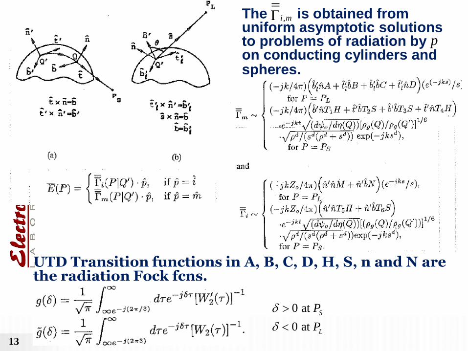
The is obtained from
uniform asymptotic solutions to problems of radiation by on conducting cylinders and spheres.
UTD Transition functions in A, B, C, D, H, S, n and N are
the radiation Fock fcns.
,i m
p
0 at
0 at
S
L
P
P
13

14
80

15

16
Geodesic
surface ray
cylindercircular afor offunction a as )T(Q' a'
75 spheroid. prolate aon apart) 90 (phased
antennaslot crossed Lindberg a of patternsRadiation
'
't
'b
'Q 'ˆ2
'ˆ1
't
'b
'Q
'n
t
b
n
curvature.
of radii principal are R and R
Q'.at directions
surface principal denote 'ˆ and'ˆ
21
21
'at ;11
2
'2sin'
Torsion ; '''
12
12
QRRRR
QT
TQQTQT gO

[1] P.H Pathak and N. Wang,”Ray analysis of mutual
coupling between antennas on a convex surface,”
IEEE Trans Ant and Propa. Vol 29 Nov 1981.
(Alt. Soln. by S.W. Lee in IEEE AP-S)
contain the UTD transition functions corresponding to surface Fock fcns.
, , and ee he eh hh
17

18
Calculated Measured
Modeling of Boeing
737 aircraft
C. L. Yu, W. D. Burnside, and M. C. Gilreath, “Volumetric pattern analysis of airborne antennas,” IEEE Trans. AP, Sep. 1978.

19
• J. J. Kim and W. D. Burnside, “Simulation and Analysis of Antennas Radiating in a Complex
Environment”, IEEE Trans. AP, April 1986.

20
-110
-100
-90
-80
-70
-60
0 4 8 12 16 20 24 28 32 36
Receive Antenna Distance from Nose (in.)
Co
up
lin
g (
dB
)
12 GHz (meas)
12 GHz (calc)
wings not present
includes double diffraction
Computed by Dr. R. J.
Marhefka at OSU-ESL
Comparison of Measured (NRL) and Calculated (NEC-BSC)
Antenna Isolation with Receiver Moving above Center of Fuselage

21
Limitations of Existing UTD Codes
• Existing UTD codes such as NEC-BSC and NEW-AIR have proven to
be successful over the past two decades.
• However, these codes are based on the approximation of the
electrically large airborne platform in terms of canonical shapes, which
is a complicated task.
• Moreover, a canonical shape representation may lead to
inaccuracies.
• Very limited capability to analyze material coatings
Canonical representation for NEC-BSC Canonical representation for NEW-AIR

22
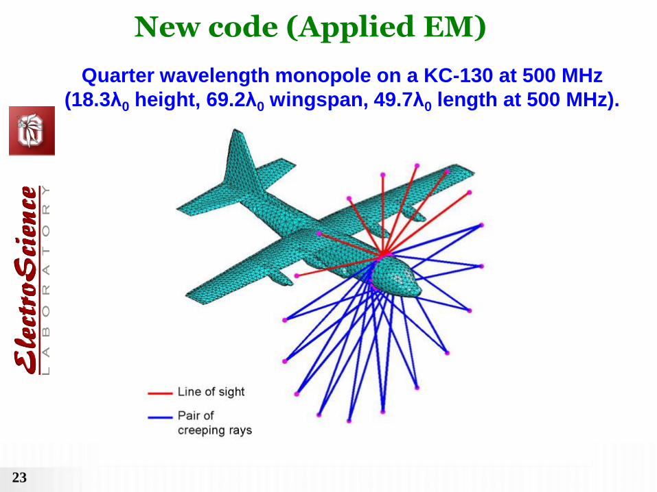
New UTD code development
•Radiating object modeled with better fidelity via
facets based on CAD geometry data.
•UTD rays tracked in presence of facets. UTD
ray parameters obtained by mapping facets back
to the original geometry (via bi-quadratic
surfaces or splines, etc).
•Does not require an expert user.
•Will eventually incorporate thin material coating
on metallic (or PEC) platform.
23
Quarter wavelength monopole on a KC-130 at 500 MHz
(18.3λ0 height, 69.2λ0 wingspan, 49.7λ0 length at 500 MHz).
New code (Applied EM)

24
Quarter wavelength monopole on a KC-130 at 500 MHz
(18.3λ0 height, 69.2λ0 wingspan, 49.7λ0 length at 500 MHz).
Mesh
Geometry
Frequency
(GHz)
# of facets
for UTD
CPU time
for UTD
# of facets for
MLFMM
CPU time for
MLFMM
KC-135 0.500 6,496 3.57 sec 420,466 1 h 28 min
Preliminary Validation
Near Field Far Field

25

26

27
Preliminary Validation

28

29
New UTD analytical development
•UTD + slope for PEC planar faced wedges with thin
material coating in form useful and accurate for
engineering applications.
•UTD + slope for curved PEC wedges with thin material
coating.
•UTD for PEC corners in curved edges and surfaces with
thin material coating.
•UTD for PEC edge excited surface (or creeping) rays
(and its reciprocal problem) in a form useful for
engineering applications.

• Material coatings are generally replaced by approximate boundary conditions (e.g. Impedance Boundary Condition [IBC])
• Solutions to canonical problems with “approx.” boundary conditions formulated exactly via Wiener-Hopf (W-H) or Maliuzhinets (MZ) methods for surfaces made up of planar structures. Ray solutions extracted analytically from them via asymptotic procedures.
• W-H method:
– J. L. Volakis and T. B. A. Senior, “Diffraction by a Thin Dielectric Half-Plane”, IEEE Trans. AP, Dec.1987
– R. G. Rojas, “Wiener-Hopf Analysis of the EM Diffraction by an Impedance Discontinuity in a Planar Surface and by an Impedance Half-Plane”, IEEE Trans. AP, Jan. 1988.
– R. G. Rojas and P. H. Pathak, “Diffraction of EM Waves by a Dielectric/Ferrite Half-Plane and Related Configurations”, IEEE Trans. AP, June 1989.
– J. L. Volakis and T. B. A. Senior, "Application of a Class of Generalized Boundary Conditions to Scattering by a Metal-Backed Dielectric Half Plane”, Proc. IEEE, May 1989.
– V. G. Daniele and G. Lombardi, “Wiener-Hopf Solution for Impedance Wedges at Skew Incidence”, IEEE Trans. AP, Sep. 2006 .
• MZ method:
– G. D. Maliuzhinets, “Excitation, Reflection and Emission of Surface Waves from a Wedge with Given Face Impedance”, Sov. Phys.-Dokl., 1958.
– R. G. Rojas, “Electromagnetic Diffraction of an Obliquely Incident Plane Wave Field by a Wedge with Impedance Faces”, IEEE AP, July 1988.
– R. Tiberio and G. Pelosi and G. Manara and P. H. Pathak, “High-Frequency Scattering from a Wedge with Impedance Faces Illuminating by a Line Source, Part I: Diffraction”, IEEE Trans. AP, Feb. 1989, see also IEEE Trans. AP, July 1993.
– M. A. Lyalinov and N.Y. Zhu, “Diffraction of a Skew Incident Plane Electromagnetic Wave by an Impedance Wedge”, Wave Motion, 2006.
• Approx. skew incidence solution (MZ) for imp. wedges based on modifying the HP solution:
– H. Syed and J. L. Volakis, “Skew incidence diffraction by an impedance wedge with arbitrary face impedances”, Electromagnetics, Vol. 15, No.3, 1995.
Previous Work on Thin Material Coated Metallic Wedge Structures
30

An Approximate UTD Ray Solution for Skew Incidence Diffraction
by Material Coated Wedges of Arbitrary Angle
T Lertwiriyaprapa, P. H. Pathak and J. L. Volakis
ElectroScience Laboratory
Department of Electrical and Computer Engineering
The Ohio State University
URSI, Chicago 2008
• Present solution based on spectral synthesis.
• Solution useful and accurate for engineering applications.
32
32
0
30
60
90
120
150
180
210
240
270
300
330
-40
-20
0dB
Grounded Material Junction
UTD-MZ
UTD
MZ
0
30
60
90
120
150
180
210
240
270
300
330
-40
-20
0dB
Grounded Material Junction
UTD-MZ
UTD
MZ
0
30
60
90
120
150
180
210
240
270
300
330
-20
-10
0dB
Grounded Material Junction
UTD-MZ
UTD
MZ
0
30
60
90
120
150
180
210
240
270
300
330
-20
-10
0dB
Grounded Material Junction
UTD-MZ
UTD
MZ
y
x
0
0
0
ˆ 0
ds
is
Semi infinite
Material Slab
Diffracted
Field
ro ,ro
z
rn ,rn
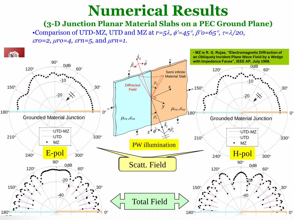
Scatt. Field
Total Field
E-pol H-pol
• MZ is R. G. Rojas, “Electromagnetic Diffraction of
an Obliquely Incident Plane Wave Field by a Wedge
with Impedance Faces”, IEEE AP, July 1988.
PW illumination
Numerical Results (3-D Junction Planar Material Slabs on a PEC Ground Plane)
•Comparison of UTD-MZ, UTD and MZ at r=5, =45, o=65, =/20, ro=2, ro=4, rn=5, and rn=1.

33
0
30
60
90
120
150
180
210
240
270
300
330
-40
-20
0dB
Coated PEC Wedge
PEC
UTD-MZ
MZ
0
30
60
90
120
150
180
210
240
270
300
330
-40
-20
0dB
Coated PEC Wedge
PEC
UTD-MZ
MZ
0
30
60
90
120
150
180
210
240
270
300
330
-40
-20
0dB
Coated PEC Wedge
UTD-MZ
MZ
0
30
60
90
120
150
180
210
240
270
300
330
-40
-20
0dB
Coated PEC Wedge
UTD-MZ
MZ
33
Scatt. Field
Total Field
z
o-face
n-face
y
x
r
P
PECo
rn ,rn
• MZ is R. G. Rojas, “Electromagnetic Diffraction of
an Obliquely Incident Plane Wave Field by a Wedge
with Impedance Faces”, IEEE AP, July 1988.
E-pol H-pol
PW o-face illumination
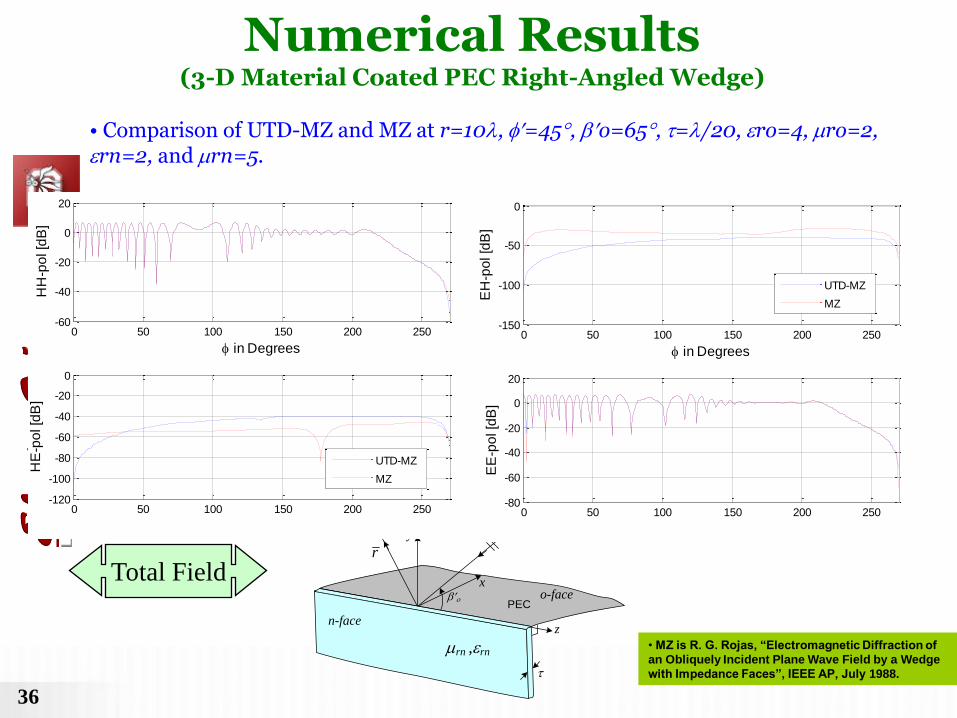
Numerical Results (3-D Material Coated PEC Right-Angled Wedge)
•Comparison of UTD-MZ and MZ at r=10, =45, o=65, =/20, rn=2, and rn=5.

34
34
Total Field
• MZ is R. G. Rojas, “Electromagnetic Diffraction of
an Obliquely Incident Plane Wave Field by a Wedge
with Impedance Faces”, IEEE AP, July 1988.
0 20 40 60 80 100 120 140 160 180-40
-20
0
20
HH
-po
l [d
B]
in Degrees
in Degrees0 20 40 60 80 100 120 140 160 180
-15
-14
-13
-12
-11
-10
HE
-po
l [d
B]
UTD-MZ
MZ
0 20 40 60 80 100 120 140 160 180-16
-14
-12
-10
EH
-po
l [d
B]
in Degrees
0 20 40 60 80 100 120 140 160 180-30
-20
-10
0
10
in Degrees
EE
-po
l [d
B]
UTD-MZ
MZ
y
x
0
0
0
ˆ 0
ds
is
Semi infinite
Material Slab
Diffracted
Field
ro ,ro
z
rn ,rn
Numerical Results (3-D Junction Planar Material Slabs on a PEC Ground Plane)
•Comparison of UTD-MZ and MZ at r=10, =45, o=65, =/20, ro=4, ro=2, rn=2, and rn=5.
35
35
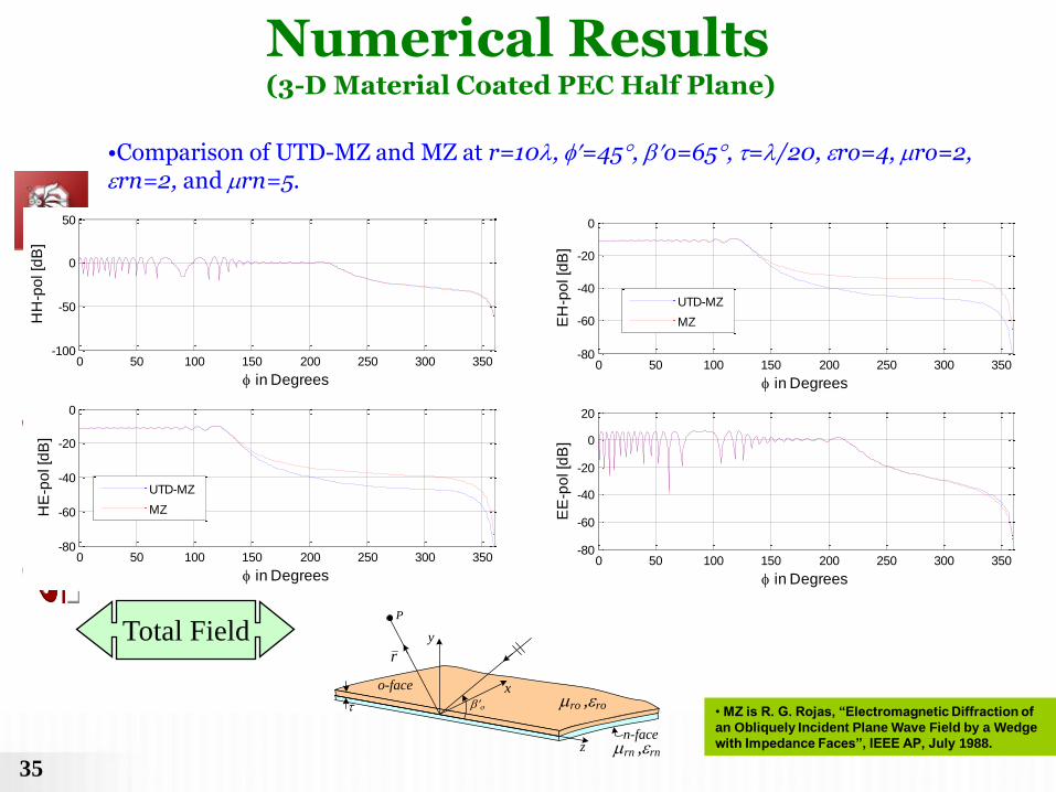
Total Field
• MZ is R. G. Rojas, “Electromagnetic Diffraction of
an Obliquely Incident Plane Wave Field by a Wedge
with Impedance Faces”, IEEE AP, July 1988. z
o-face
y
x
r
P
n-face
o ro ,ro
rn ,rn
0 50 100 150 200 250 300 350-100
-50
0
50
HH
-po
l [d
B]
in Degrees
0 50 100 150 200 250 300 350-80
-60
-40
-20
0
in Degrees
HE
-po
l [d
B]
UTD-MZ
MZ
0 50 100 150 200 250 300 350-80
-60
-40
-20
0
EH
-po
l [d
B]
in Degrees
0 50 100 150 200 250 300 350-80
-60
-40
-20
0
20
in DegreesE
E-p
ol [d
B]
UTD-MZ
MZ
Numerical Results (3-D Material Coated PEC Half Plane)
•Comparison of UTD-MZ and MZ at r=10, =45, o=65, =/20, ro=4, ro=2, rn=2, and rn=5.
36
36
Total Field
z
o-face
n-face
y
x
r
P
PECo
rn ,rn• MZ is R. G. Rojas, “Electromagnetic Diffraction of
an Obliquely Incident Plane Wave Field by a Wedge
with Impedance Faces”, IEEE AP, July 1988.
0 50 100 150 200 250-150
-100
-50
0
EH
-po
l [d
B]
in Degrees
0 50 100 150 200 250-80
-60
-40
-20
0
20
EE
-po
l [d
B]
UTD-MZ
MZ
0 50 100 150 200 250-60
-40
-20
0
20
HH
-po
l [d
B]
in Degrees
0 50 100 150 200 250-120
-100
-80
-60
-40
-20
0
HE
-po
l [d
B]
UTD-MZ
MZ
Numerical Results (3-D Material Coated PEC Right-Angled Wedge)
• Comparison of UTD-MZ and MZ at r=10, =45, o=65, =/20, ro=4, ro=2, rn=2, and rn=5.

0
30
60
90
120
150
180
210
240
270
300
330
-40
-20
0
Coated PEC Wedge
TE
TM
37
Scatt. Field Total Field
0
30
60
90
120
150
180
210
240
270
300
330
-40
-20
0
Coated PEC Wedge
TE
TM
Numerical Results (3-D Material Coated PEC Wedge, WA = 54o)
• r=5, =117, =66, r=5,=/20,rn=2.4, and rn=8.
Slope diffraction
is included
z-directed current
moment excitation

ANTENNAS ON CONVEX COATED
STRUCTURES • A Uniform Geometrical Theory of Diffraction (UTD) Ray Solution is developed to predict the radiation by antennas on smooth convex metallic surfaces with thin material coating.
• Metallic surface is assumed to be a perfect electric conductor (PEC).
• Thin coating ; ; = surface radii of curvature
Also,
• For sufficiently thin material coating, one can approximate the actual boundary on the external surface by a surface impedance Zs
gkd k2
k
g
)( , rr
ˆ ˆ sn n E Z n H1
21 ( )1 (1 )
2o
r rr r
r
s jZ kdkd
Z
sZ
n
Arbitrarily oriented electric or magnetic point current at Q’ on external boundary
d (coating thickness)
PL
Q’
Q
Ps PEC
Direct Ray
Surface diffracted Ray
Geodesic surface ray
Thin uniform material coating
1kd
38

MOTIVATION
•UTD Ray Analysis can be applied to analyze radiation by conformal antennas and antenna arrays in the presence of a smooth PEC convex surface with thin material coating.
Single printed patch Printed patch array
Printed cross dipole element
d PEC
Single slot
Slot array
d PEC
Single monopole
39

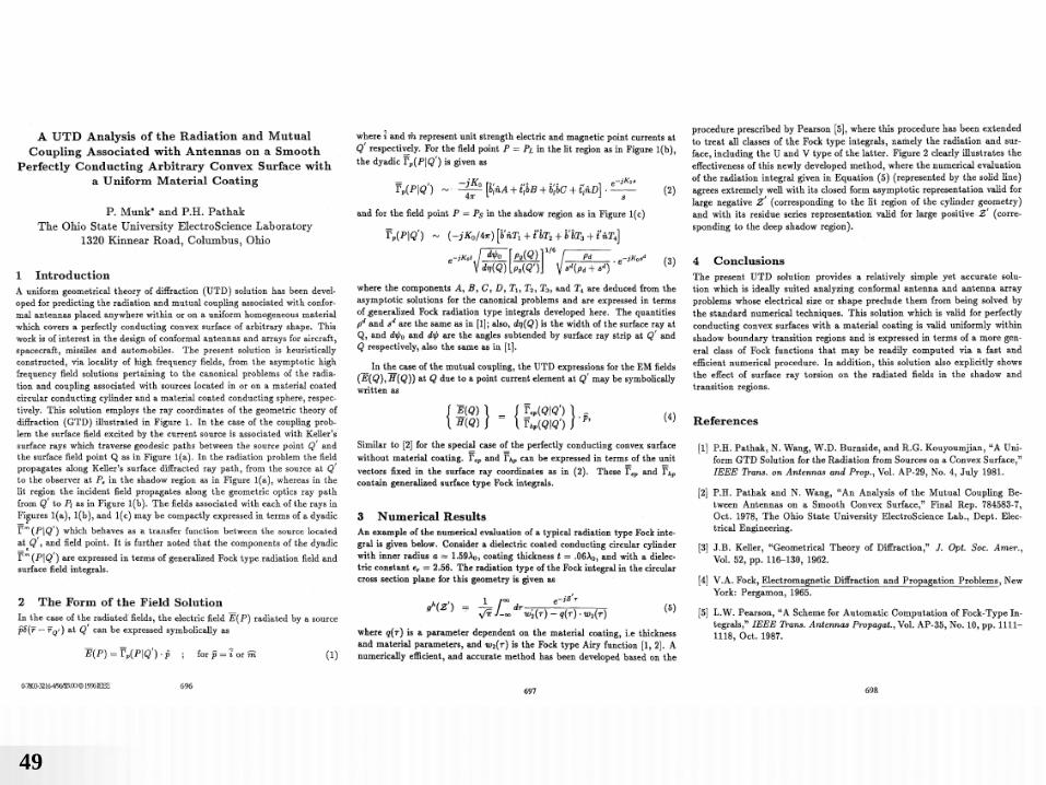
SOME PREVIOUS RELATED WORK
[1] P. Munk and P. H. Pathak, "A UTD Analysis of the Radiation and Mutual Coupling Associated with Antennas on a Smooth Perfectly Conducting Arbitrary Convex Surface with a Uniform Material Coating," Antennas and Propagation Society International Symposium, vol. 1, pp. 696 - 699, Jul. 1996.
- UTD ray solution not in form convenient for applications. Also, not all UTD transition functions computed.
[2] N. A. Logan and K. S. Lee, "A Mathematical Model for Diffraction by Convex Surface," In Electromagnetic waves. R. ranger, Ed, Univ. Wisconsin Press, 1962.
- No specific ray solution for radiation available.
[3] Wait, J. R., Electromagnetic Waves in Stratified Media, A Pergamon Press Book, McMillan Co., New York, 1962.
- Propagation of waves around the earth, spherical surface analyzed. No UTD ray solution presented
- Similar to work by V. A. Fock, Electromagnetic Diffraction and Propagation Problems, New York, Pergamon Press, 1965 (Original work in Russian was published in 1940s)
[4] L. W. Pearson, “A scheme for automatic computation of Fock-type integrals,” IEEE Trans. Antennas Propagat.,vol. AP-35, pp. 1111–1118, Oct. 1987.
- Solution presented for only the scattering into shadow region of a coated circular cylinder.
[5] C. Tokgöz, P. H. Pathak and R. J. Marhefka," An Asymptotic Solution for the Surface Magnetic Field Within the Paraxial Region of a Circular Cylinder With an Impedance Boundary Condition", IEEE Trans. Antennas Propagat., vol. 53, no. 4, April 2005.
- Mostly restricted to surface fields on cylinders due to point magnetic currents on the same surface.
[6] P. H. Pathak, N. Wang, W. D. Burnside and R. G. Kouyoumjian, “A uniform GTD solution for the radiation from sources on a convex surface”, IEEE Trans. Antennas Propagat., vol. AP-29, no. 4, pp. 609-622, July 1981.
- UTD analysis restricted to smooth convex PEC surfaces.
[7] P. H. Pathak, R. J. Burkholder, Y. Kim and J. Lee, "A Hybrid Numerical-Ray Based Analysis of Large Convex Conformal Antenna Array on Large Platforms," Presented at ACES conference in Finland, April, 2010.
- Hybrid numerical UTD solution restricted to complex antennas on locally smooth convex PEC surfaces.
40

ANALYTICAL FORMULATION • A UTD solution for radiation by an arbitrarily oriented or on an arbitrary
smooth convex surface with a uniform surface impedance boundary condition (IBC) is developed from canonical solutions.
(Prabhakar Pathak & Kittisak Phaebua)
• Canonical problems to be solved pertain to (or ) with arbitrary orientation on circular cylinders and spheres with IBC.
• Generalization of canonical solutions to arbitrary convex surface performed heuristically based on the principal of locality of HF wave phenomena
edp mdp
( )edp Q ( )mdp Q
(a) Canonical circular cylinder problem geometry (b) Canonical spherical problem geometry
41

10 20 30 40
30
210
60
240
90270
120
300
150
330
180
0
Ray Solution
CST-Microwave Studio
NUMERICAL RESULTS (CYL)
Radius of cylinder 4
Thickness of dielectric coating 0.02
Length of cylinder 50
2.1 (Teflon)r
1r
at 80oE at 60oE
at 90oE
Frequency of operation = 10 GHz
10 20 30 40
30
210
60
240
90270
120
300
150
330
180
0
Ray Solution
CST-Microwave Studio
10 20 30 40
30
210
60
240
90270
120
300
150
330
180
0
Ray Solution
CST-Microwave Studio
ˆNormal electric current source, ( . )J J n
42

NUMERICAL RESULTS (CYL)
at 90oE
ˆTangential magnetic current source, M ( . )t M b
Radius of cylinder 4
Thickness of dielectric coating 0.02
Length of cylinder 50
2.1 (Teflon)r
1r
Frequency of operation = 10 GHz
10 20 30 40
30
210
60
240
90270
120
300
150
330
180
0
Ray Solution
CST-Microwave Studio
43

NUMERICAL RESULTS (SPH)
nE E
ˆNormal electric current source, ( . )rJ J n ˆTangential magnetic current source, M ( . )t M b
Radius of sphere 4
Thickness of dielectric coating 0.02 2.1 (Teflon) ; r 1r
Frequency of operation = 10 GHz
10 20 30 40 50
30
210
60
240
90270
120
300
150
330
180
0
Ray Solution
CST-Microwave Studio
10 20 30 40
30
210
60
240
90270
120
300
150
330
180
0
Ray Solution
CST-Microwave Studio
nE E
44

45
A UTD Diffraction Coefficient for a
Corner Formed by Truncation of Edges
in an Otherwise Smooth Curved Surface
Giorgio Carluccio(1), Matteo Albani(1), and Prabhakar H. Pathak(2)
(1) Department of Information Engineering, University of Siena
Via Roma 56, 53100 Siena, Italy, http://www.dii.unisi.it
(2) ElectroScience Laboratory, The Ohio State University
1320 Kinnear Road, 43212 Columbus – OH, USA,
http://electroscience.osu.edu
IEEE International Symposium on Antennas and Propagation
and USNC/URSI NationalRadio Science Meeting
June 01-05, 2009

46
UTD Vertex Diffraction Coefficient
Shadow Boundary Cones (SBCs) and Shadow Boundary Planes (SBPs):

47 -180 -150 -120 -90 -60 -30 05
10
15
20
25
30
[dB
]
Tot UTD
Tot Uniform Asym PO
-180 -150 -120 -90 -60 -30 0-10
-5
0
5
10
15
20
25
30
[dB
]
GO
D-UTD-AB
D-UTD-DA
V-UTD-A
Tot
-4 -2 0 2-4-202
-3
-2
-1
0
1
2
3
4
5
BC
Geometria
x
A
D
z
y
III Example: Vertex Double Transition
Scan Center on the Vertex A
Field E
3 , 45 , 180 0r
We consider a smooth convex parabolic surface
illuminated by an electric point source
Field E
48
Remarks
• A UTD diffraction coefficient for a corner formed by truncation of edges in a
smooth curved surface was presented.
• A PO diffraction coefficient is derived by asymptotical evaluation of the PO
integral, to understand how the surface curvature affects the diffracted field
transitional behavior.
• The UTD diffraction coefficient was obtained by heuristically modifying the
UTD diffraction coefficient for a corner in a flat surface, on the basis of the
previous PO result.
• Numerical examples show how the proposed diffracted coefficient smoothly
compensates for the abrupt discontinuity occurring when the GO field or the
singly diffracted at edges abruptly vanish.
• Valid for astigmatic ray tube illumination.
• Can be extended to include thin material coating.
49

50
o-facen-face
SSB
direction
PS
PL
QE Qi t
o
'Pi
e
PEC
Edge excited surface rays
• Presently UTD solution has been obtained for ISB and SSB far
apart.
• Work is in progress to obtain an asymptotic solution useful for
engineering applications when ISB and SSB regions overlap.

51
Comments
• Keller’s original GTD is not valid at and near ISB, RSB, SSB (i.e. in
SB transition regions).
• UTD developed to patch Keller’s original theory within the SB
transition regions.
• GTD corrects GO, and GTD = GO + diffraction
• UTD corrects GTD, but usually UTD GTD outside SB transition
regions.
• UTD ray paths remain independent of frequency.
• UTD offers an analytical (generally closed form) solution to many
complex problems that can not otherwise be solved in an analytical
fashion.
• UTD in some cases must be augmented by PO/PTD or ECM

• PO/PTD can give rise to spurious contributions from the shadow boundary line in a smooth body.
• PO/PTD does not incorporate creeping wave effects.
•PO can correct for UTD transport singularities at and near the confluence of edge induced GO ray shadow boundaries and GO/diffracted ray caustics (e.g. forward radiation from parabolic reflector antennas).
RSB + diffracted caustic
offset paraboloidal reflector
reflected ray caustic
feed
52

SPECTRAL THEORY OF DIFFRACTION (STD)
• UTD/GTD requires a RAY OPTICAL incident field
• If the incident field is NON-RAY OPTICAL, then it must be represented by: a) continuous set of PLANE WAVES (e.g. Plane Wave
Spectrum) b) discrete set of RAY OPTICAL fields
• Each constituent RAY OPTICAL field in the SPECTRAL
DECOMPOSITION of a NON-RAY OPTICAL incident wave can be treated by UTD.
• The total UTD solution is then a summation of the UTD response to each constituent RAY OPTICAL incident field
R. Tiberio, G. Manara, G. Pelosi, R. KouyoumJian: ‘’HF EM scattering of plane waves from
double wedges,” IEEE Trans AP-37, pp. 1172-1180, Sept. 1989
Y. Rahmat-Samii, R. Mittra ‘’A spectral domain interpretation of HF phenomena,” IEEE
Trans AP-25 pp. 676-687, Sept. 1977
53

54

55
ECM for Interior Waveguide
Discontinuities

Previous related work
56

ADDITIONAL COMMENTS ON ASYMPTOTIC HF
METHODS
• Asymptotic HF methods are powerful for analyzing a wide variety of electrically large EM problems.
• Conventional CEM numerical solution methods based on self consistent wave formulations become rapidly inefficient, or even intractable, for solving large ‘’EM problems’’.
• UTD is more developed, especially for handling smooth convex boundary diffraction.
• HF wave optical methods (PO, PTD, ITD, SBR) have not directly incorporated creeping waves.
• Ray optical methods require ray tracing. More efficient but less robust. Ray paths independent of frequency.
• Wave optical methods require numerical integration on the large object. Less efficient but more robust. Does not scale with frequency.
57

58
59
Caustic
Parabolic
Reflector
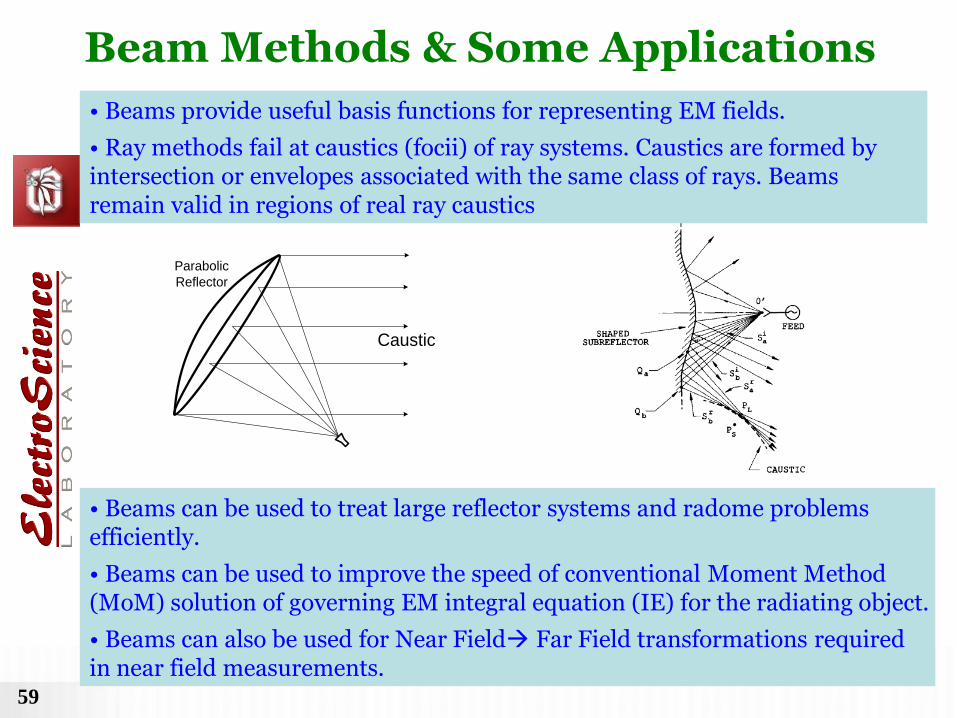
Beam Methods & Some Applications
• Beams provide useful basis functions for representing EM fields.
• Ray methods fail at caustics (focii) of ray systems. Caustics are formed by intersection or envelopes associated with the same class of rays. Beams remain valid in regions of real ray caustics
• Beams can be used to treat large reflector systems and radome problems efficiently.
• Beams can be used to improve the speed of conventional Moment Method (MoM) solution of governing EM integral equation (IE) for the radiating object.
• Beams can also be used for Near Field Far Field transformations required in near field measurements.

60
• UTD for real source excitation of wedge developed
via first order Pauli-Clemmow method (PCM) [1-4] for
asymptotic solution of canonical wedge diffraction
integral along a steepest descent path (SDP)
•First order PCM not strictly valid (for poles crossing
the SDP away from saddle point); hence analytic
continuation of UTD for complex source location
without further study is questionable!
•First order Van der Waerden method (VWM) [1-4] is
valid even where PCM fails.
y
x
EQ~O
z
)2(
n
WA
,,r
'~,'
~,'~ r
Complex Source Beam (CSB) Diffraction by a Wedge
• However, one can show that the first order VWM method, upon using a key rearrangement
(and combination) of terms, yields:
PCM) (Extended EPCMΔPCMVWM Key Step
• Next, for the special wedge case of interest, it is shown analytically (and verified numerically)
that . 0
)negligible is (since UTD UTD EUTD
for wedge EUTD EPCM VWM
for wedge UTD PCM :Note
For a wedge
Therefore, analytic continuation
of UTD for a wedge is OK for
complex waves
1. T. B. A. Senior and J. L. Volakis, “Approximate Boundary Conditions in Electromagnetics,” The Institute of Electrical Engineerings, London, 1995.
2. L. B. Felsen and N. Marcuvitz, “Radiation and Scattering of Waves,” Englewood Cliffs, NJ: Prentice-Hall, 1973.
3. C. Gennarelli and L. Palumbo, “A uniform asymptotic expansion of typical diffraction integrals with many coalescing simple pole singularities and a
first-order saddle point,” IEEE Trans. Antennas and Propagat., vol. AP-32, pp. 1122-1124, Oct. 1984.
4. R. G. Rojas, “Comparison between two asymptotic methods,” IEEE Trans. Antenn- as and Propagation, vol. 35, no. 12, pp 1492-1493, Dec 1987.
61
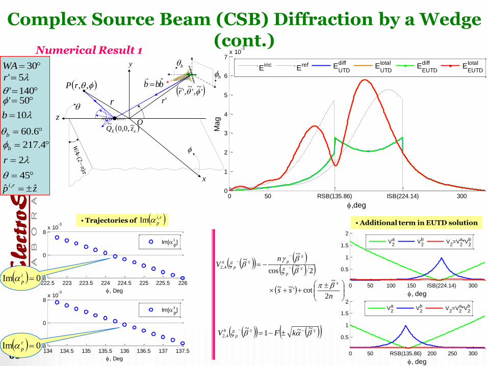
Numerical Result 1
bbb ˆ
y
x
eE zQ ~,0,0~ O
z
'~,'
~,'~ r
)2(
n
WA
b
b
,,rP
r 'r
0 50 RSB(135.86) ISB(224.14) 3000
1
2
3
4
5
6
7x 10
-3
,deg
Ma
g
Einc
Eref E
UTD
diffE
UTD
totalE
EUTD
diffE
EUTD
total
0 50 100 150 ISB(224.14) 300
0.5
1
1.5
2
, deg
0 50 RSB(135.86) 200 250 300
0.5
1
1.5
2
, deg
V2a V
2b V
2=V
2a*V
2b
V2a V
2b V
2=V
2a*V
2b
222.5 223 223.5 224 224.5 225 225.5 226-8
0
8x 10
-3
, Deg
Im[pi ]
134 134.5 135 135.5 136 136.5 137 137.5-8
0
8x 10
-3
, Deg
Im[pr ]
• Additional term in EUTD solution • Trajectories of
0Im r
p
0Im i
p
nss
nV
p
p
p
a
2
~
cot'~~
2~
cos
~~
4,2
~~1
~4,2
kFV p
b
ri
p
,Im
30WA
10b
6.60b
4.217b
2r
45
zp ri ˆˆ ,
5'r
140' 50'
Complex Source Beam (CSB) Diffraction by a Wedge (cont.)

62
0 50 RSB(112.37) 150 200 ISB(247.67) 3000
0.2
0.4
0.6
0.8
1
1.2
1.4
1.6
x 10-3
, degM
ag
Einc
Eref E
UTD
diffE
UTD
totalE
EUTD
diffE
EUTD
total
Numerical Result 2
246.5 247 247.5 248 248.5 249-0.015
0
0.015
, Deg
Im[pi ]
111 111.5 112 112.5 113 113.5-0.015
0
0.015
, Deg
Im[pr ]
0 50 100 150 200 ISB(247.67) 300
0.5
1
1.5
2
, deg
0 50 RSB(112.37)150 200 250 300
0.5
1
1.5
2
2.5
, deg
V2a V
2b V
2=V
2a*V
2b
V2a V
2a V
2=V
2a*V
2b
bbb ˆ
y
x
eE zQ ~,0,0~O
z
'~,'
~,'~ r
)2(
n
WA
bb
,,rP
r 'r
• Additional term in EUTD solution • Trajectories of
0Im r
p
0Im i
p
nss
nV
p
p
p
a
2
~
cot'~~
2~
cos
~~
4,2
~~1
~4,2
kFV p
b
ri
p
,Im
45WA
10b
57.78b
57.258b
12r
40
zp ri ˆˆ ,
20'r
100' 70'
Complex Source Beam (CSB) Diffraction by a Wedge (cont.)

63 SB1(5.3) 40 60 80 100 120 140 SB2(174.7)0
0.01
0.02
0.03
0.04
0.05
0.06
0.07
0.08
0.09
0.1
, deg
Ma
g
HzPCM H
zEPCM
Surface Wave 58.35jZS
0 20 SB1(54.7) 80 100 SB2(125.3) 160 1800
0.1
0.2
0.3
0.4
0.5
0.6
0.7
0.8
0.9
, deg
Ma
g
HzPCM H
zEPCM
Leaky Wave 79.1794.327 jZS
2sin2
2,142,1
pp
j
pp e
M
y
x
jXRZ s Shadow boundaries are determined when
0Im 2,1 pp
Other Complex Waves

64
SHARP BLADE
“Bright” Keller Cone of
Diffraction
Laser beam incident in the
plane of the sharp blade
LASERBEAM
Keller Cone of Edge Diffraction

65
Sequence
of CSP
beamsFeed
Antenna
Reflected &
Diffracted Fields of
each CSP beam
Feed
Radiation
Pattern
Fast analysis of the reflector antennas.
Radome
AntennaCSP beams
Antenna radiation in the presence of radomes.
• A GB -UTD (PO based) method was previously
reported in [1].
• With the CSP method, feed pattern is expanded
into a set of CSBs.
• Each CSP beam field is scattered from the
reflector by using complex extension of UTD.
• A 2-D case for a single beam illumination was
reported in [2].
• This new fully 3-D CSP-UTD approach (UTD for
beams) is expected to be more accurate then [1].
• The field of the antenna is first expanded into
a set of CSP beams.
• Each beam is next tracked through the
radome.
• The transmitted beams are summed up at
the observer location.
• Complex ray tracing can be employed for
beam tracking through the radome [3,4].
[1] H. T. Chou, P. H. Pathak and R. J. Burkholder, “Novel Gaussian Beam Method for the Rapid Analysis of Large Reflector Antennas”, IEEE Trans. Antennas
Propagat., 2001
[2] G.A.Suedan and E.V. Jull, ”Beam diffraction by planar and parabolic reflectors,” IEEE Trans. Antennas Propagat., 1991.
[3] X. J. Gao and L. B. Felsen, “Complex ray analysis of beam transmission through two-dimensional radomes”, IEEE Trans. Antennas Propagat., 1985
[4] J. J. Maciel and L. B. Felsen, “Gaussian beam analysis of propagation from an extended plane aperture distribution through dielectric layers, part 1 - plane
layer,” IEEE Trans. Antennas Propagat., 1990.
Large Antenna Applications
66
fm
x
y
z
QB
'~r
b
O
Finite
Parabolic Reflector
Infinite
Parabolic Reflector
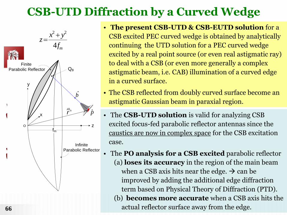
p • The CSB-UTD solution is valid for analyzing CSB
excited focus-fed parabolic reflector antennas since the
caustics are now in complex space for the CSB excitation
case.
• The PO analysis for a CSB excited parabolic reflector
(a) loses its accuracy in the region of the main beam
when a CSB axis hits near the edge. can be
improved by adding the additional edge diffraction
term based on Physical Theory of Diffraction (PTD).
(b) becomes more accurate when a CSB axis hits the
actual reflector surface away from the edge.
• The present CSB-UTD & CSB-EUTD solution for a
CSB excited PEC curved wedge is obtained by analytically
continuing the UTD solution for a PEC curved wedge
excited by a real point source (or even real astigmatic ray)
to deal with a CSB (or even more generally a complex
astigmatic beam, i.e. CAB) illumination of a curved edge
in a curved surface.
• The CSB reflected from doubly curved surface become an
astigmatic Gaussian beam in paraxial region.
mf
yxz
4
22
CSB-UTD Diffraction by a Curved Wedge

67 -50 0 50 100 150 200 250
0.2
0.4
0.6
0.8
1
1.2
, deg
MA
G
EPO
ECSB-EUTD
ECSB-UTD
Numerical Result : Finite parabolic reflector illuminated by a CSB
-50 0 50 100 150 200 250
0.2
0.4
0.6
0.8
1
1.2
1.4
, deg
MA
G
EPO
ECSB-EUTD
ECSB-UTD Mf
yxz
4
22
y
z
b
5000r
QB
SfM
y
xOO
QB
S
dM
h
)270,100,40(),50,10(,ˆˆ,10,35,5,60 SQbpbfhd BMM
Symmetry Plane
Transverse Plane
CSB-UTD Diffraction by a Curved Wedge (cont.)

68
Numerical Result : Finite parabolic reflector illuminated by a CSB
-50 0 50 100 150 200 250
0.1
0.2
0.3
0.4
0.5
, deg
MA
G
EPO
ECSB-EUTD
ECSB-UTD
-50 0 50 100 150 200 250
0.1
0.2
0.3
0.4
0.5
0.6
0.7
, deg
MA
G
EPO
ECSB-EUTD
ECSB-UTD Mf
yxz
4
22
y
z
b
5000r
QB
SfM
y
xOO
QB
S
dM
h
)270,100,40(),60,20(,ˆˆ,10,35,5,60 SQbpbfhd BMM
Symmetry Plane
Transverse Plane
CSB-UTD Diffraction by a Curved Wedge (cont.)

69
Numerical Result : Finite parabolic reflector illuminated by a CSB
-50 0 50 100 150 200 250
0.05
0.1
0.15
0.2
0.25
, deg
MA
G
EPO
ECSB-EUTD
ECSB-UTD
-50 0 50 100 150 200 250
0.05
0.1
0.15
0.2
, deg
MA
G
EPO
ECSB-EUTD
ECSB-UTD
Mf
yxz
4
22
y
z
b
5000r
QB
SfM
y
xOO
QB
S
dM
)90,0,40(),10,17(ˆˆ,10,30,50 SQxpbfd BMM
Symmetry Plane
Transverse Plane
CSB-UTD Diffraction by a Curved Wedge (cont.)

70
Numerical Result : Finite parabolic reflector illuminated by a CSB
-50 0 50 100 150 200 250
0.5
1
1.5
2
, deg
MA
G
EPO
ECSB-EUTD
ECSB-UTD
-50 0 50 100 150 200 250
5
10
15
20
, deg
MA
G
EPO
ECSB-EUTD
ECSB-UTD
Mf
yxz
4
22
y
z
b
200r
QB
SfM
y
xOO
QB
S
dM
)0,10,40(),35,20(ˆˆ,15,30,50 SQbpbfd BMM
Symmetry Plane
Transverse Plane
CSB-UTD Diffraction by a Curved Wedge (cont.)

71
Sequence of
CSBs/GBsFeed
Antenna
Reflected &
Diffracted Fields
of Each CSB/GB
Feed
Radiation
Pattern
Feed
Radiation
GB
Expansion
n = launching points in feed plane
m = number of GBs from each n
CSBs/GBs Illuminating a reflector

72
< 200 GBs
NUM-PO
Time < 5 min/iter
Time = 5 or 6 hrs/iter
Approx. 30 iter’s*
Offset Shaped Reflector for CONUS Contour Beam Using GBs
85D
* Rahmat-Samii’s paper
Normalized co-polarized contours based on the GB approach CONUS
coverage by a shaped concave reflector with a feed pattern at 12 GHz
with l =18.51. Approximately 200GBs were used.
Normalized co-polarized gain contours based on the numerical PO
integration approach for the same shaped reflector case as above. ?

73
Conclusions
• CSB expansion methods for EM radiation are
presented employing three different variants of the
surface equivalence theorem.
• The analytical properties (validity region, truncation,
etc.) of the approach are investigated.
• It is shown that accurate and efficient field
representations can be obtained by conveniently
truncating the beam expansion.
• It is demonstrated that the expansion idea is applicable
to a class of EM radiation/scattering problems.

74
Band Width/Complexity Materials
Ele
ctr
ica
l S
ize
UTD
PO/GO
MOM
FEM
MLFMM
Hybrid Methods are
required for in-situ
analysis
Source:
http://www.feko.info/feko-
product-info/technical
Computational Methods

75
Hybrid Method & Some Applications
• In many applications, large antennas (arrays) and large antenna platforms contain both large and small features in terms of wavelength.
•For electrically large parts on radiating object, UTD ray method is useful but not valid for electrically small portions.
•For highly inhomogeneous and electrically small region (e.g. complex antenna elements/arrays) the FE-BI or numerical methods are useful, and UTD is not applicable here.
•A hybrid combination of FE-BI (or other suitable numerical methods) and UTD could handle the entire problem not otherwise tractable by each single approach by itself.
76
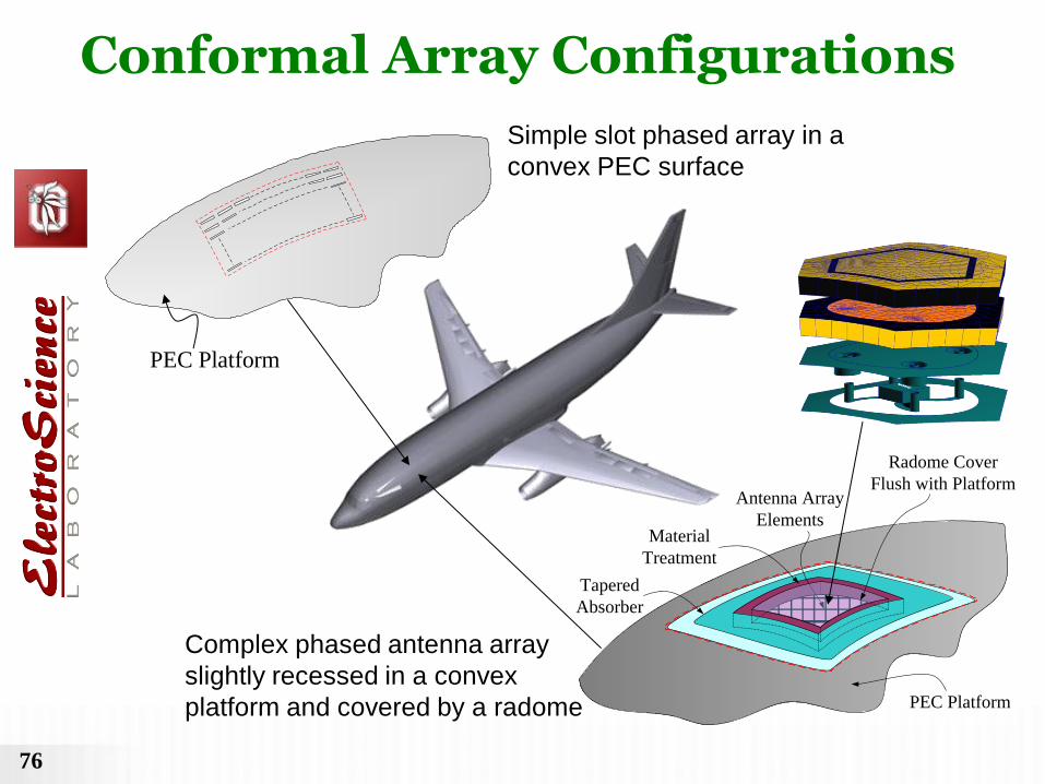
Simple slot phased array in a
convex PEC surface
Material
Treatment
Tapered
Absorber
Antenna Array
Elements
Radome Cover
Flush with Platform
PEC Platform
PEC Platform
Complex phased antenna array
slightly recessed in a convex
platform and covered by a radome
Conformal Array Configurations

77
Local Array Part
treated by full wave
numerical methods.
Present Collective
UTD Solution
converts numerical
array solution into
rays launched from
array aperture.
External Platform Part
Collective UTD rays launched
from aperture efficiently
excite external platform which
is analyzed by UTD.
Proposed Hybrid Numerical-UTD Approach

78
Actual problem
A local array modeling
for FEM
Complex Array
Platform (e.g. part of aircraft)
Array+Radome
Combination
PEC
Local UTD Ray
eq
sM
Structure outside the local
aperture region is ignored
A local array modeling
for FE-BI
ABC
Local Array Part Treated by FEM, FE-BI

79
• Collective UTD rays launched by array
aperture distribution obtained via numerical
solution to local array part.
• Collective UTD rays launched from a few flash
points in the array aperture.
PEC smooth
convex surface
Observation
point
Collective UTD Rays

80
Array
Aperture
Part of
Hypothetical
Airborne Platform
Direct
Multipath
• Collective UTD rays efficiently launched from array aperture interact with external platform.
• Rays from platform could interact back with the array and so on. These effects can be included if desired.
• Collective UTD surface rays provide direct coupling between two arrays located on the same platform.
Convex Surface
Observation
point
External Platform Interaction Part
81
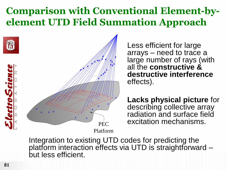
Less efficient for large arrays – need to trace a large number of rays (with all the constructive & destructive interference effects).
Lacks physical picture for describing collective array radiation and surface field excitation mechanisms.
Integration to existing UTD codes for predicting the platform interaction effects via UTD is straightforward – but less efficient.
PEC
Platform
Comparison with Conventional Element-by-element UTD Field Summation Approach
82
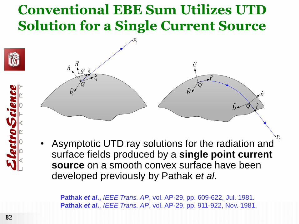
• Asymptotic UTD ray solutions for the radiation and surface fields produced by a single point current source on a smooth convex surface have been developed previously by Pathak et al.
Pathak et al., IEEE Trans. AP, vol. AP-29, pp. 609-622, Jul. 1981.
Pathak et al., IEEE Trans. AP, vol. AP-29, pp. 911-922, Nov. 1981.
.
.
nn
lt
ˆlb
s
Q
LP
i
.
n
n
t
b
t
Q
SP
.Q
.
b
Conventional EBE Sum Utilizes UTD Solution for a Single Current Source

83
• Antenna array operated at 25 GHz (K-band); = 1.2 cm
• Aperture size = 1 ft. × 1 ft. = 25.4 × 25.4
• If sampling at every /4, one needs 102×102 (10,404) sample points and needs to trace such large number of rays.
• Conventional UTD approach becomes less efficient than collective UTD approach.
Hypothetical Example
Material
Treatment
Tapered
Absorber
Antenna Array
Elements
Radome Cover
Flush with Platform
PEC PlatformPEC
Platform
Example of a LARGE Array

84
Describes fields produced by the whole array aperture at once in terms of only a few UTD rays arising from specific points in the interior, and on the boundary of the array aperture – highly efficient.
Provides physical picture for describing collective array radiation and surface field excitation mechanisms.
Integration to most existing UTD codes for predicting the platform interaction effects via UTD is not direct because it requires some code modifications to allow for a new input description.
PEC smooth
convex surface
Observation
point
Present Collective UTD Ray Approach

85
• A scanning phased array on a slowly varying
convex platform can be modeled by a parametric
surface patch, such as a bi-quadratic surface, etc.
uv
x
y
z
11r
12r
13r
21r
31r
32r
33r
22r
23r
u
v
0 1
1
1/2
1/2
uv-plane
Curved Surface Modeling

86
( )
1
( ( , ))i iu v
Kj u v
i
i
A r u v C e
* Fields produced by each TW can be represented in terms of a set of UTD rays.
Found numerically by matching to the actual distribution
• A traveling wave (TW) expansion for realistic aperture
distributions obtained from FEM, FE-BI, etc.
u v
uv-space
Traveling Wave Expansion

87
• DFT (Discrete Fourier Transform)
• CLEAN (or “Extract and Subtract”)
• Prony’s Method
• Other Available Methods
TW Extraction Methods

88
PEC smooth
convex surface
Observation
point
u v
Each TW current radiates a small set of collective UTD rays.
1
( )K
l
UTD
l
E P E
4 4 4
1 1 1
GO ed cd GO ed
UTD GO i ei j i
i j i
E E U E U E E E
Transition fields
Collective UTD Ray Fields

89
A
ssQ
ie
je
x
y
z
ˆssn
ssQ .
.Pˆ
sss
ˆ ( )u sst Q
ˆ ( )v sst Q
ss
u
ss
v
1 2
1 2( )( )ss
ss ssjksGO
ss ss ss
ss ss
E A es s
Astigmatic Ray Field
ˆ( | )ss L ss ssA T P Q L
( ' )( 2 ) ( )ssjk Qss
ss
ss
j J QL e
k
Geometrical Optics or Local Floquet Wave

90
A
ie
je
,s eiQ
x
y
z ,ˆ ( )u s eit Q
,ˆ
s ein
,s eiQ
ˆeis
.P
.,s ei
u
ie
( )eijksd ei
ei ei
ei ei ei
E A es s
Conical Wave Lit Region
,ˆ( | ) d
ei L s ei eiA T P Q D
,/ 4 ( )
,
2
2 ( )
ˆ[ ] | |
s eij jk Q
ei s eid
ei
ei v v ei u
j e J Q eD
k s r k E
Edge Diffracted Fields

91
A
ie
je
,s eiQ
( )
dei
djksds s ei
ei ei d d d
ei ei ei
E A es s
Shadow Region
x
y
z
eiQ.
.SP
eiQ.
d
eis
ie
1/ 6
,,
,
, ,
( )( )ˆ( | )
( ) ( )ei g s eis eijkts ds
ei S s ei ei
s ei g s ei
Qd QA T P Q D e
d Q Q
,/ 4 ( )
,
2
2 ( )
ˆ[ ] | |
s eij jk Q
ei s eids
ei
ei v v ei u
j e J Q eD
k t r k E
Edge-Excited Surface Diffracted Fields

92
x
y
z
ˆcin
ciQ.
.P ˆ
cisSpherical Wave
ijjks
c
ij ij
ij
eE A
s
Lit Region
A
ie
je
ijQ
ˆ( | ) c
ij L ij ijA T P Q D
( )
2
( )
ˆ ˆ[ ][ ]
ijjk Q
ei ej ijc
ij
ij u u ij v v
J Q eD
k s r s r
Corner Diffracted Fields

93
( )
dij
d
jksijcs s
ij ij d d d
ij ij ij
E A es s
Shadow Region
x
y
z
ciQ.
.SP
ciQ.
d
cis
A
ie
je
ijQ
1/ 6
0( )
ˆ( | )( ) ( )
ijjkt g ijs cs
ij S s ij ij
ij g ij
QdA T P Q D e
d Q Q
( )
2
( )
ˆ ˆ[ ][ ]
ijjk Q
ei ej ijcs
ij
ij u u ij v v
J Q eD
k t r t r
Corner-Excited Surface Diffracted Fields

94
2( )2 4 4
, ,21 3
( , , , )4
ijj k
GO GO
ci j ei cj i ej ei ej
i j ij
eE E W k k k k
k
2( )
2 42
1
1 ( )2
eij k
ei ei ei
i ei
eF k U
k
2( )
4 42
3
1 ( )2
ejj k
ej ej ej
j ej
eF k U
k
2,( )
4 42
,
3 ,
1 ( )2
ci jj k
d d
ei ei ci j ej
j ci j
eE E F k
k
2 2 2 2
1 1 2 22 21 21 1 2 2 1 2
1 2 1 1 2 2
( , , , ) ( ) ( )x y x yx x
W x y x y F x F xy y x y x y
1 21 1 2 2
1 2
( , , , )y y
T x y x yx x
Fields in Transition Regions
95
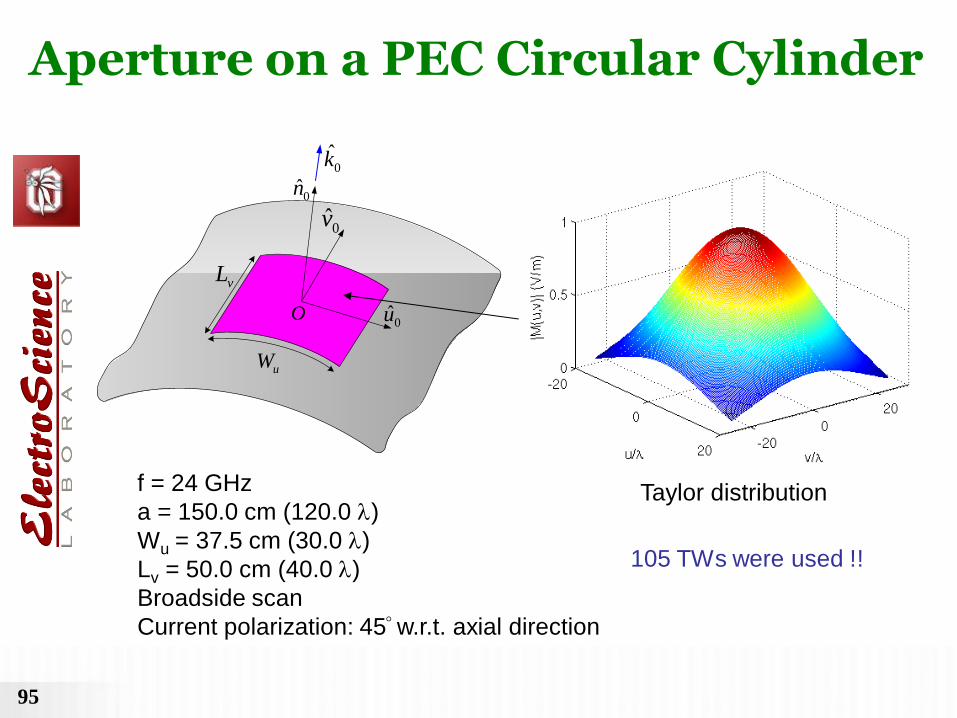
Taylor distribution
vL
uW
0n
0u
0v
O
0k
f = 24 GHz
a = 150.0 cm (120.0 )
Wu = 37.5 cm (30.0 )
Lv = 50.0 cm (40.0 )
Broadside scan
Current polarization: 45 w.r.t. axial direction
105 TWs were used !!
Aperture on a PEC Circular Cylinder

96
vL
uW
0n
0u
0v
r
O
Circumferential plane cut
r = 40 (near zone)
REF: 25.36 sec.
TW-UTD: 3.78 sec.
Aperture on a PEC Circular Cylinder (cont.)
97
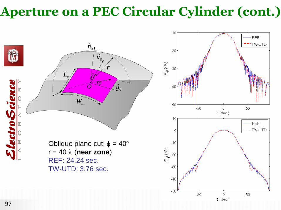
Oblique plane cut: = 40
r = 40 (near zone)
REF: 24.24 sec.
TW-UTD: 3.76 sec.
vL
uW
0n
0u
0v
r
O
Aperture on a PEC Circular Cylinder (cont.)

98
Circumferential plane cut
r = 9600 (far zone)
REF: 31.25 sec.
TW-UTD: 4.18 sec.
0v
0u
0n
vLuW
a O
r
Aperture on a PEC Circular Cylinder (cont.)
99
0v
0u
0n
a
0k
0
0O
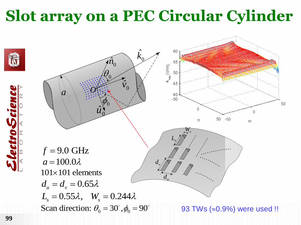
0 0Scan direction: 30 , 90
0.55 , 0.244s sL W
9.0 GHzf
100.0a
0.65u vd d
101 101 elements
93 TWs (0.9%) were used !!
sW
vd
ud
sL
Slot array on a PEC Circular Cylinder

100
Axial plane cut (scan plane) r = 100 (near zone)
REF: 34.57 sec.
TW-UTD: 5.47 sec.
0n
0u
0vr
O
Slot array on a PEC Circular Cylinder (cont.)

101
Oblique plane cut: = 60
r = 100 (near zone)
REF: 38.40 sec.
TW-UTD: 6.12 sec.
0n
0u
0v
r
O
Slot array on a PEC Circular Cylinder (cont.)
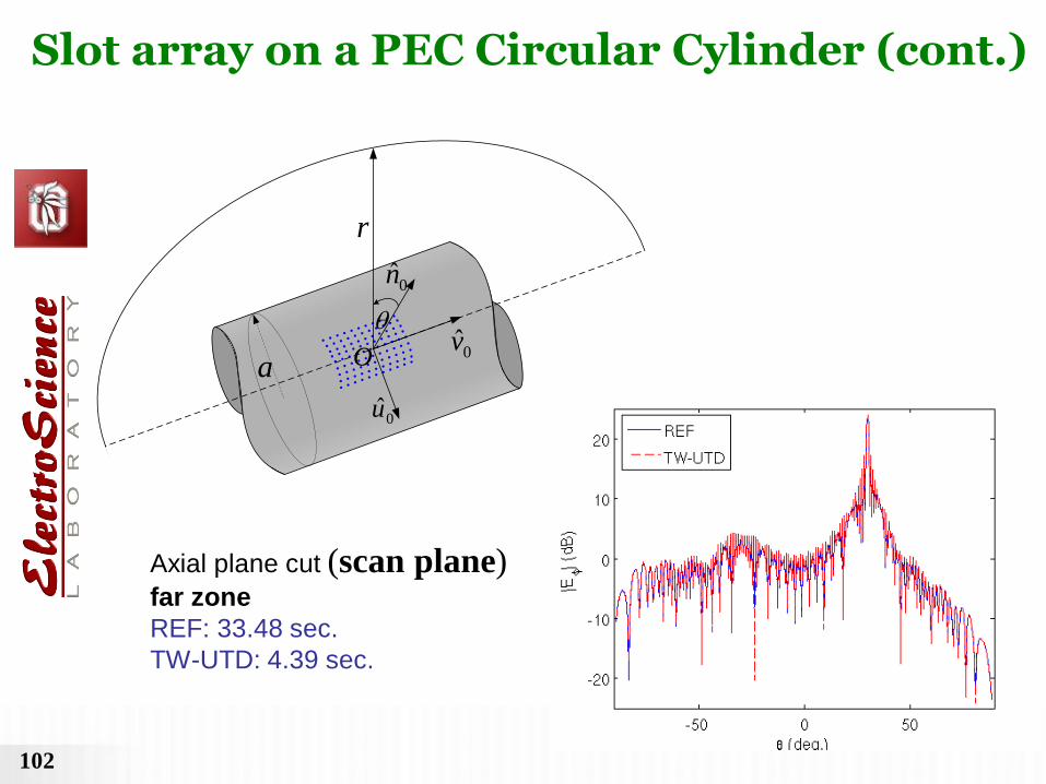
102
0v
0u
0n
r
a
O
Axial plane cut (scan plane) far zone
REF: 33.48 sec.
TW-UTD: 4.39 sec.
Slot array on a PEC Circular Cylinder (cont.)

103
Oblique plane cut: = 45
far zone
REF: 51.39 sec.
TW-UTD: 6.08 sec.
0v
0u
0n
a
O
r
Slot array on a PEC Circular Cylinder (cont.)

104
Interface between Full-Wave solver and High Frequency method
J-F. Lee’s DD FEBI code.

105
Solution of 7 by 7 Vivaldi array mounted on F16 Platform

106
Solution of 7 by 7 Vivaldi array mounted on F16 Platform

107
20 by 20 Vibaldi array mounted on larger platform
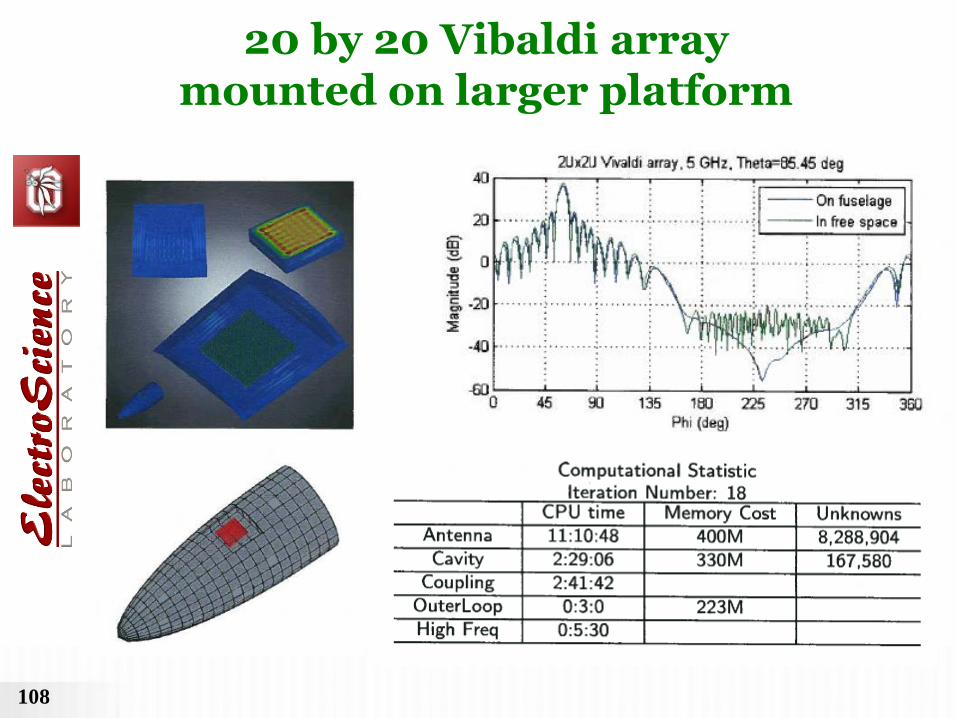
108
20 by 20 Vibaldi array mounted on larger platform

109
Conclusions
• An asymptotic UTD ray solution has been developed for describing, in a collective fashion, the fields radiated by large conformal antenna arrays on a doubly curved, smooth convex surface. • The present solution will provide an efficient link between the local array part to be analyzed numerically and the full external platform part to be analyzed by UTD, in a hybrid method for analyzing large complex antenna phased arrays integrated into a realistic complex platform. • The present collective UTD ray solution shows a good agreement with the conventional element-by-element UTD field summation solution.

110
The Ohio State Univ. (OSU), ElectroScience Lab.(ESL),
Columbus, Ohio, USA (1)Prof. Robert J.Burkholder
(2)Dr. Youngchel Kim
(3)Dr. His-Tseng Chou (now Prof. at Yuan-Ze Univ. Taiwan ROC)
(4)Dr. Titipong Lertwriyaprapa
(5)Dr. Pawuwat Janpugdee (Now member of research staff at
TEMASEK Labs. NUS, Singapore)
(6)Dr. Koray Tap (Now at ASELSAN, Ankara, Turkey)
(7)Prof. W.D. Burnside
(8)Dr. R.J. Marhefka
(9)Dr. Nan Wang
(10)Prof. Jin-Fa Lee
The work presented is done in conjunction with the following researchers
Univ. of Siena, Italy (1)Giorgio Carluccio
(2)Prof. Matteo Albani
(3)Prof. Stefano Maci
Applied EM (1)Dr. Cagatay Tokgoz
(2)Dr. C. J. Reddy