device management. so far… we have covered cpu and memory management computing is not interesting...
TRANSCRIPT

Device Management

So far…
We have covered CPU and memory management
Computing is not interesting without I/OsDevice management: the OS
component that manages hardware devicesProvides a uniform interface to access devices
with different physical characteristicsOptimize the performance of individual devices
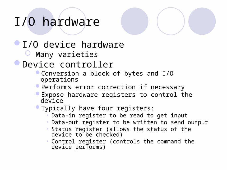
I/O hardware
I/O device hardware Many varieties
Device controllerConversion a block of bytes and I/O operationsPerforms error correction if necessaryExpose hardware registers to control the deviceTypically have four registers:
• Data-in register to be read to get input• Data-out register to be written to send output• Status register (allows the status of the device to be
checked)• Control register (controls the command the device performs)

Device Addressing
How the CPU addresses the device registers?
Two approachesDedicated range of device addresses in the
physical memoryRequires special hardware instructions associated with
individual devicesMemory-mapped I/O: makes no distinction
between device addresses and memory addressesDevices can be accessed the same way as normal
memory, with the same set of hardware instructions

Device Addressing Illustrated
Primarymemory
Device 1
Device 2
Memoryaddresses
Memory-mapped I/Os
Primary memory
Deviceaddresses
Separate deviceaddresses
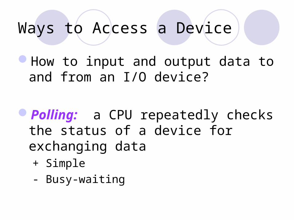
Ways to Access a Device
How to input and output data to and from an I/O device?
Polling: a CPU repeatedly checks the status of a device for exchanging data+ Simple
- Busy-waiting

Ways to Access a Device
Interrupt-driven I/Os: A device controller notifies the corresponding device driver when the device is available+ More efficient use of CPU cycles
- Data copying and movements
- Slow for character devices (i.e., one interrupt per keyboard input)
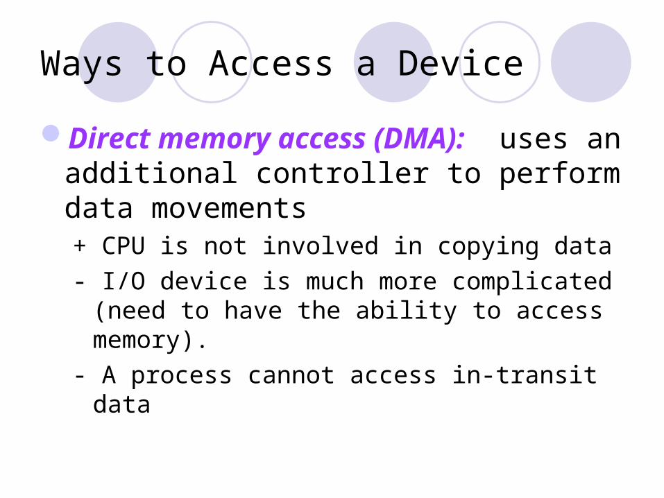
Ways to Access a Device
Direct memory access (DMA): uses an additional controller to perform data movements+ CPU is not involved in copying data
- I/O device is much more complicated (need to have the ability to access memory).
- A process cannot access in-transit data

Ways to Access a Device
Double buffering: uses two buffers. While one is being used, the other is being filled.Analogy: pipeliningExtensively used for graphics and animation
So a viewer does not see the line-by-line scanning

Device Driver
An OS component that is responsible for hiding the complexity of an I/O device
So that the OS can access various devices in a uniform manner

Types of IO devices
Two categories A block device stores information in fixed-size blocks, each
one with its own addresse.g., disks
A character device delivers or accepts a stream of characters, and individual characters are not addressable
e.g., keyboards, printers, network cards
Device driver provides interface for these two types of devices Other OS components see block devices and character
devices, but not the details of the devices. How to effectively utilize the device is the responsibility of the
device driver
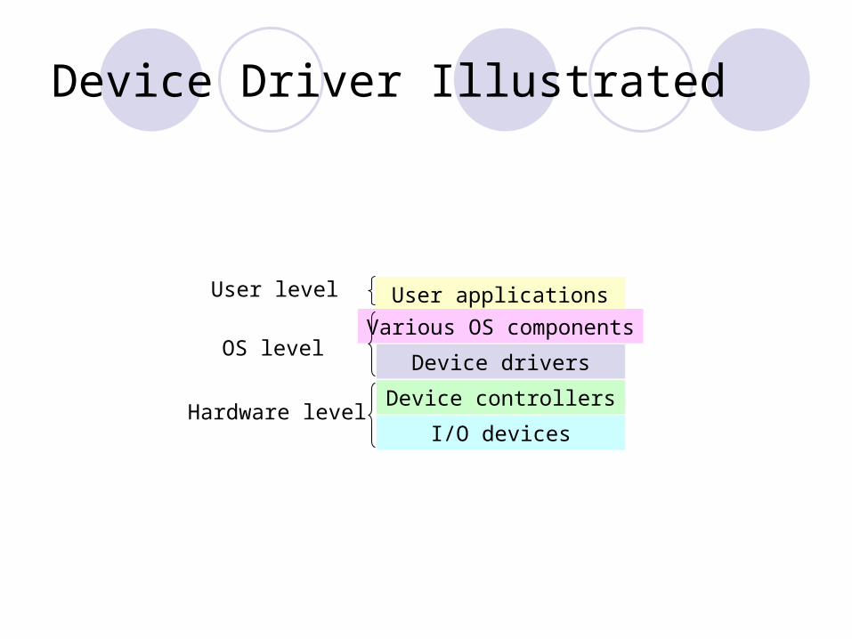
Device Driver Illustrated
User applications
Various OS components
Device drivers
Device controllers
I/O devices
User level
OS level
Hardware level

Disk as An Example Device
30-year-old storage technologyIncredibly complicatedA modern drive
250,000 lines of micro code
Disk Characteristics
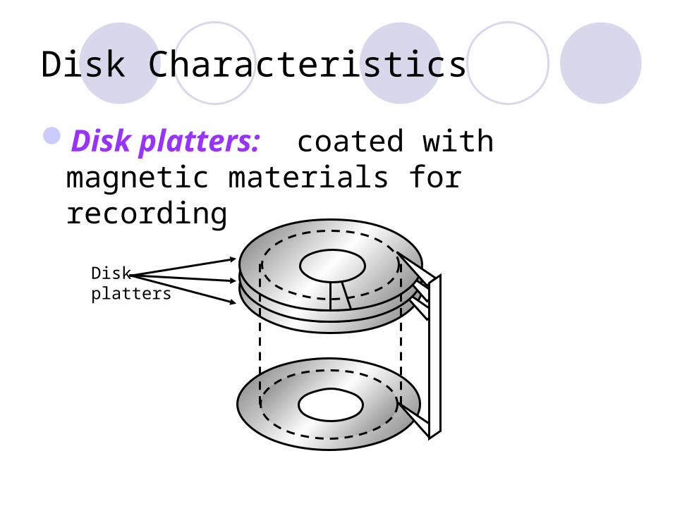
Disk platters: coated with magnetic materials for recording
Disk platters

Disk Characteristics
Disk arm: moves a comb of disk headsOnly one disk head is active for reading/writing
Disk platters
Disk arm
Disk heads

Hard Disk Trivia…
Aerodynamically designed to flyAs close to the surface as possibleNo room for air molecules
Therefore, hard drives are filled with special inert gas
If head touches the surfaceHead crashScrapes off magnetic information

Disk Characteristics
Each disk platter is divided into concentric tracks
Disk platters
Disk arm
Disk heads
Track
Disk Characteristics
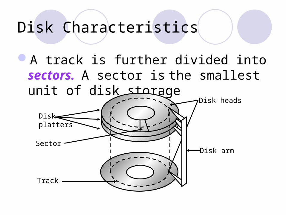
A track is further divided into sectors. A sector is the smallest unit of disk storage
Disk platters
Disk arm
Disk heads
Track
Sector

Disk Characteristics
A cylinder consists of all tracks with a given disk arm position
Disk platters
Disk arm
Disk heads
Track
Sector
Cylinder

Disk Characteristics
Cylinders are further divided into zones
Disk platters
Disk arm
Disk heads
Track
Sector
Cylinder
Zones
Disk Characteristics
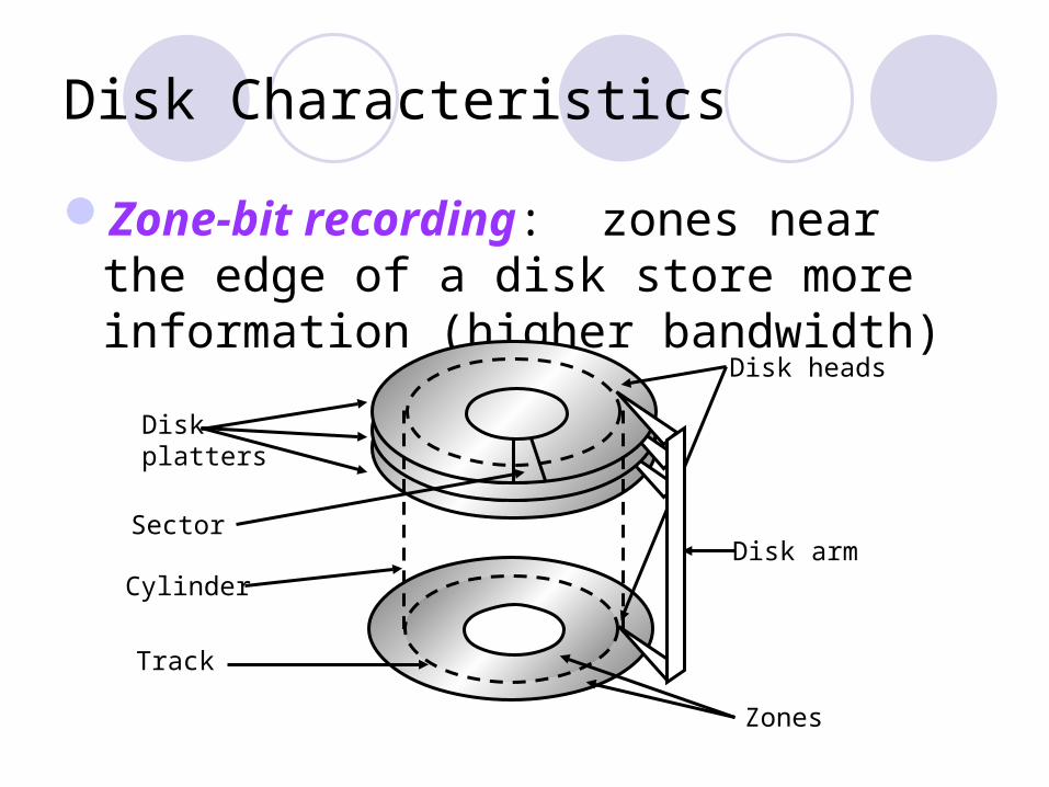
Zone-bit recording: zones near the edge of a disk store more information (higher bandwidth)
Disk platters
Disk arm
Disk heads
Track
Sector
Cylinder
Zones
More About Hard Drives Than You Ever Want to Know
Track skew: starting position of each track is slightly skewedMinimize rotational delay when sequentially transferring
bytes across tracks
Thermo-calibrations: periodically performed to account for changes of disk radius due to temperature changes
Typically 100 to 1,000 bits are inserted between sectors to account for minor inaccuracies

Disk Access Time
Seek time: the time to position disk heads (~8 msec on average)
Rotational latency: the time to rotate the target sector to underneath the headAssume 7,200 rotations per minute (RPM)7,200 / 60 = 120 rotations per second1/120 = ~8 msec per rotationAverage rotational delay is ~4 msec

Disk Access Time
Transfer time: the time to transfer bytesAssumptions:
58 Mbytes/sec4-Kbyte disk blocks
Time to transfer a block takes 0.07 msec
Disk access time Seek time + rotational delay + transfer time
Disk Performance Metrics
Latency Seek time + rotational delay
BandwidthBytes transferred / disk access time

Examples of Disk Access Times
If disk blocks are randomly accessedAverage disk access time = ~12 msecAssume 4-Kbyte blocks4 Kbyte / 12 msec = ~340 Kbyte/sec
If disk blocks of the same cylinder are randomly accessed without disk seeksAverage disk access time = ~4 msec4 Kbyte / 4 msec = ~ 1 Mbyte/sec
Examples of Disk Access Times
If disk blocks are accessed sequentiallyWithout seeks and rotational delaysBandwidth: 58 Mbytes/sec
Key to good disk performanceMinimize seek time and rotational latency

Disk Tradeoffs
Larger sector size better bandwidthWasteful if only 1 byte out of 1 Mbyte is
needed
Sector size Space utilization Transfer rate
1 byte 8 bits/1008 bits (0.8%) 80 bytes/sec (1 byte / 12 msec)
4 Kbytes 4096 bytes/4221 bytes (97%) 340 Kbytes/sec (4 Kbytes / 12 msec)
1 Mbyte (~100%) 58 Mbytes/sec (peak bandwidth)

Disk Controller
Few popular standardsIDE (integrated device electronics)ATA (AT attachment interface)SCSI (small computer systems interface)
DifferencesPerformanceParallelism
Disk Device Driver
Major goal: reduce seek time for disk accessesSchedule disk request to minimize disk arm
movements
Disk Arm Scheduling Policies
First come, first serve (FCFS): requests are served in the order of arrival+ Fair among requesters- Poor for accesses to random disk blocks
Shortest seek time first (SSTF): picks the request that is closest to the current disk arm position+ Good at reducing seeks- May result in starvation

Disk Arm Scheduling Policies
SCAN: takes the closest request in the direction of travel (an example of elevator algorithm)
+ no starvation
- a new request can wait for almost two full scans of the disk
Disk Arm Scheduling Policies
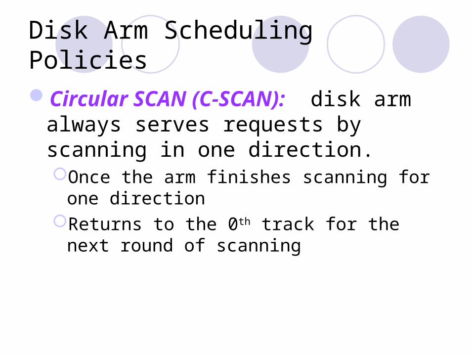
Circular SCAN (C-SCAN): disk arm always serves requests by scanning in one direction. Once the arm finishes scanning for one
directionReturns to the 0th track for the next round of
scanning

First Come, First Serve
Request queue: 3, 6, 1, 0, 7Head start position: 2Total seek distance: 1 + 3 + 5 + 1 + 7 =
17
Tracks
0
5
4
3
2
1
6
7
Time

Shortest Seek Distance First
Request queue: 3, 6, 1, 0, 7Head start position: 2Total seek distance: 1 + 2 + 1 + 6 + 1 =
10
Tracks
0
5
4
3
2
1
6
7
Time

SCAN
Request queue: 3, 6, 1, 0, 7Head start position: 2Total seek distance: 1 + 1 + 3 + 3 + 1 = 9
Time
Tracks
0
5
4
3
2
1
6
7
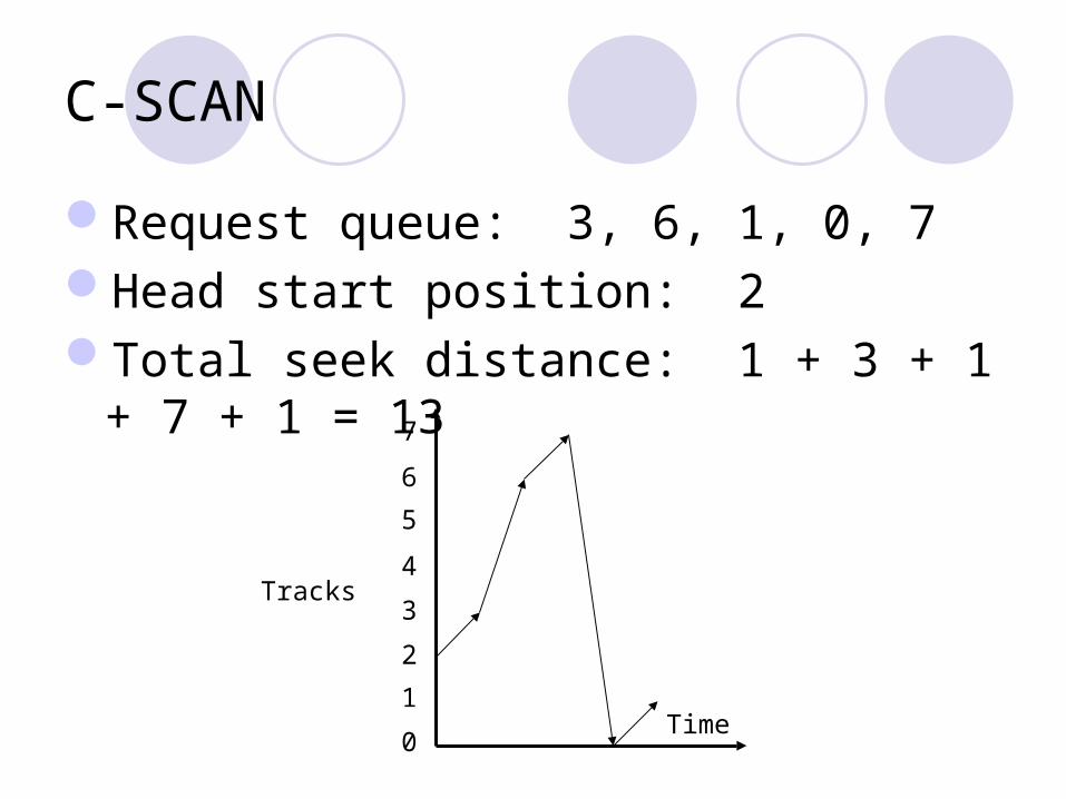
C-SCAN
Request queue: 3, 6, 1, 0, 7Head start position: 2Total seek distance: 1 + 3 + 1 + 7 + 1 =
13
Time
Tracks
0
5
4
3
2
1
6
7
Look and C-Look
Similar to SCAN and C-SCAN the arm goes only as far as the final request in
each direction, then turns around Look for a request before continuing to move in a
given direction.