dft test point insertion
TRANSCRIPT

8/10/2019 DFT Test Point Insertion
http://slidepdf.com/reader/full/dft-test-point-insertion 1/21
8/10/2019 DFT Test Point Insertion
http://slidepdf.com/reader/full/dft-test-point-insertion 2/21
ASIC_TEST D Q
F2SE
. . .
D Q
F3SE
0
1
Reset
Synchronizer
D Q
SEF0
D Q
SE
RSTn
F1
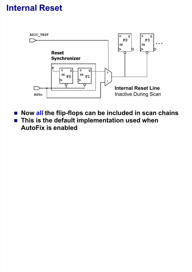
Internal Reset
Now all the flip-flops can be included in scan chains This is the default implementation used when
AutoFix is enabled
Internal Reset Line
Inactive During Scan

8/10/2019 DFT Test Point Insertion
http://slidepdf.com/reader/full/dft-test-point-insertion 3/21
ASIC_TEST D Q
F2SE
. . .
D Q
F3SE
Reset
Synchronizer
D Q
SEF0
D Q
SE
RSTn
F1
2nd solution
Now all the flip-flops can be included in scan chains SA1 fault on internal reset line is still untestable
Internal Reset Line
Inactive During Scan
1-Injector

8/10/2019 DFT Test Point Insertion
http://slidepdf.com/reader/full/dft-test-point-insertion 4/21
ASIC_TEST D Q
F2SE
. . .
D Q
F3SE
Reset
Synchronizer
D Q
SEF0
D Q
SE
RSTn
F1
Another Internal-Reset Solution
All the flip-flops can be included in scan chains Full test coverage on the internal reset line Internal reset line is controlled by the Reset
Synchronizer output during scan capture
Network N 9
Internal Reset Line
Inactive During Shift
TEST_SE
Reset Line gated
with a ScanEnable
signal (TEST_SE)

8/10/2019 DFT Test Point Insertion
http://slidepdf.com/reader/full/dft-test-point-insertion 5/21
Autofix
The AutoFix feature can automatically fix DFT ruleviolations associated with:
Uncontrollable clocks
Uncontrollable asynchronous set/reset signals
Three-state signals
Bidirectional signals

8/10/2019 DFT Test Point Insertion
http://slidepdf.com/reader/full/dft-test-point-insertion 6/21
Logic Added by AutoFix
AutoFix adds a configurable test-point architecture Exact implementation can vary during optimization
Test Point
Gate View
DataIn
Data
Out
Test Mode
Test
Data
0
1
Test- Pt
Enable
Test
Mode

8/10/2019 DFT Test Point Insertion
http://slidepdf.com/reader/full/dft-test-point-insertion 7/21
ASIC_TEST
DIV_CLK
INT_CLK
0
1 ATE_CLK
Examples of AutoFix Test Points
AutoFix MUXing
for Divided Clockor Asynch
AutoFix Reset MUX
for Uncontrolled Reset
(default option)
ASIC_TEST
INT_RSTn
SYNC_RSTn 0
1PI_RSTn
INT_RSTn
ScanEnableINT_RST_GATED
AutoFix Reset Gate-method gate

8/10/2019 DFT Test Point Insertion
http://slidepdf.com/reader/full/dft-test-point-insertion 8/21
General Test Point Insertion
The AutoFix client can be used for specific types oflogic fixing
Other logic fixing requirements can be handled by
User Defined Test Points

8/10/2019 DFT Test Point Insertion
http://slidepdf.com/reader/full/dft-test-point-insertion 9/21
User Defined Test Points (UDTP)

8/10/2019 DFT Test Point Insertion
http://slidepdf.com/reader/full/dft-test-point-insertion 10/21
User Defined Test Points
UDTPs direct DFTC to insert control and observepoints at user specified locations in the design
Why use UDTP? Fix uncontrollable clocks and/or asynch pins
Increase the test coverage of the design
Reduce the pattern count

8/10/2019 DFT Test Point Insertion
http://slidepdf.com/reader/full/dft-test-point-insertion 11/21
Types of User Defined Test Points
The following types of user defined test points aresupported in DFT Compiler
Force
force_0, force_1, force_01, force_z0,
force_z1, force_z01 Control
control_0, control_1, control_01,control_z0, control_z1, control_z01
Observe
observe

8/10/2019 DFT Test Point Insertion
http://slidepdf.com/reader/full/dft-test-point-insertion 12/21
Specifying a Test Point Element
Use the command:set_test_point_element
This command allows the users to specify the
location and the type of test points along with a set
of options in order to achieve their test pointrequirements

8/10/2019 DFT Test Point Insertion
http://slidepdf.com/reader/full/dft-test-point-insertion 13/21
Test Point Types
The type of test point to be inserted can bespecified as follows:
set_test_point_element [pin list]
–type <test_point_type>
Pin list specifies the location at which UDTP will be
inserted. It is a required argument
The type of test points can be force, control or
observe
Remember: Only one “type” of test point
can be specified with each invocation ofthe set_test_point_element command

8/10/2019 DFT Test Point Insertion
http://slidepdf.com/reader/full/dft-test-point-insertion 14/21
UDTP Types
Force_01
test_mode
0 or 1
DinDout
Force_0 or Force_1
test_point_clock
Q
SI
0
test_mode
scan_inscan_out
DoutDin
CTR
scan_enable
D
Control_01Control_0 or Control_1
D Q
SI
0scan_in
scan_out
test_mode
D Q
SI
0
test_point_clock
DinDout
CTR
TPE
scan_enabletest_mode0 or 1
D Q
SI
0
test_point_clock
scan_out
DinDout
scan_in
TPE
scan_enable
D Q
SI scan_inscan_out
test_point_clock
Din
scan_enableOBS
Observe

8/10/2019 DFT Test Point Insertion
http://slidepdf.com/reader/full/dft-test-point-insertion 15/21
How to specify Control and Clock signals
Control Signal:Must have been previously defined as a
TestMode or
ScanEnable
set_test_point_element pin_list –type control_01 \–control_signal port_name|pin_name
Clock Signal:Must have been previously defined as a ScanClock
set_test_point_element pin_list –type control_01 \–clock_signal port_name|pin_name
D
Q SI
0scan_in
scan_out
test_modeport_namepin_name D
Q
SI
0
test_point_clockport_namepin_name
DinDout
CTR
TPE
scan_enable
Control_01

8/10/2019 DFT Test Point Insertion
http://slidepdf.com/reader/full/dft-test-point-insertion 16/21
D Q
SI 0
test_mode
scan_inscan_out
Dout
Din
CTR
scan_enable
Enabling Control or Observe Registers
Enables or disables the insertion ofcontrol, force, or observe scan registers
set_test_point_element
[-scan_source_or_sink enable | disable]
Default is “enable”
D
Q
SI scan_inscan_out
test_point_clock
Din
scan_enableOBS
Control/ObserveRegister

8/10/2019 DFT Test Point Insertion
http://slidepdf.com/reader/full/dft-test-point-insertion 17/21
Specifying a Control Source or Observe Sink
The user can specify the name of the source signal
(for control or force points) or sink signal (forobserve points)
set_test_point_element
[-source_or_sink existing_pin_or_port] This option is valid only for control or observe test
point types, when register insertion is disabled
test_mode
source_pinDout
Din
sink_pin
Din
Control Source Pin or Port Observe Sink Pin or Port

8/10/2019 DFT Test Point Insertion
http://slidepdf.com/reader/full/dft-test-point-insertion 18/21

8/10/2019 DFT Test Point Insertion
http://slidepdf.com/reader/full/dft-test-point-insertion 19/21
Specifying a Test Point Enable
User can optionally specify a test point enable pin or port for
control points with the–test_point_enable option
set_test_point_element pin_list –type test_point_type
[-test_point_enable existing_pin_or_port]
If the name of the enable point is not supplied then DFTC
creates a new port called test_point_enable
This option is valid only for control test points
Must supply an unconnected pin
D Q
SI
0scan_in
scan_out
test_mode
test_point_clock
DinDout
CTR
scan_enable
test_point_enable

8/10/2019 DFT Test Point Insertion
http://slidepdf.com/reader/full/dft-test-point-insertion 20/21
Test Point Register Sharing
D
Q SI 0scan_in
test_mode
D Q
SI
0
test_point_clock
Din1Dout1
CTR
TPE
scan_enable
Din2Dout2
D Q
SI 0
TPE
scan_out
D Q
SI
OBS
scan_in
scan_out
test_point_clock
Din1
scan_enable
Din2
Control_01
Observe
Sharing Control or Observe scan registers
set_test_point_element pin_list–type test_point_type \
–test_points_per_scan_source_or_sink 2 (default: 8)

8/10/2019 DFT Test Point Insertion
http://slidepdf.com/reader/full/dft-test-point-insertion 21/21
Test Point Enable Register Sharing
Control_01
Sharing Control Test Point Enable Registers
This option is valid only for the control test point types
set_test_point_element pin_list –type test_point_type \
–test_points_per_test_point_enable 2 (default: 1)
D Q
SI
0scan_in
test_mode
D
Q SI
0
test_point_clock
Din1Dout1
CTR
TPE
scan_enable
Din2Dout2
scan_out