dhp-r &dp - danfoss heatingheating.danfoss.com/pcmpdf/df_dhp-r eco_ig_vmilf102... · ⚠⚠the...
TRANSCRIPT
VMILF102
DHP-R
InstallatIon InstRuctIonsExPansIon moDulE, HPc Em
coolIng moDulE, HPc cm

VMILF1022 – Danfoss VMBQI102
VMBQI102 VMILF102 Danfoss – 3
table of contentsInstallation for WCS function (warm water loading) . . . 4
Installation for TWC function (tap water control) . . . . . . 6
Installation for Shunt function . . . . . . . . . . . . . . . . . . . . . . . 8
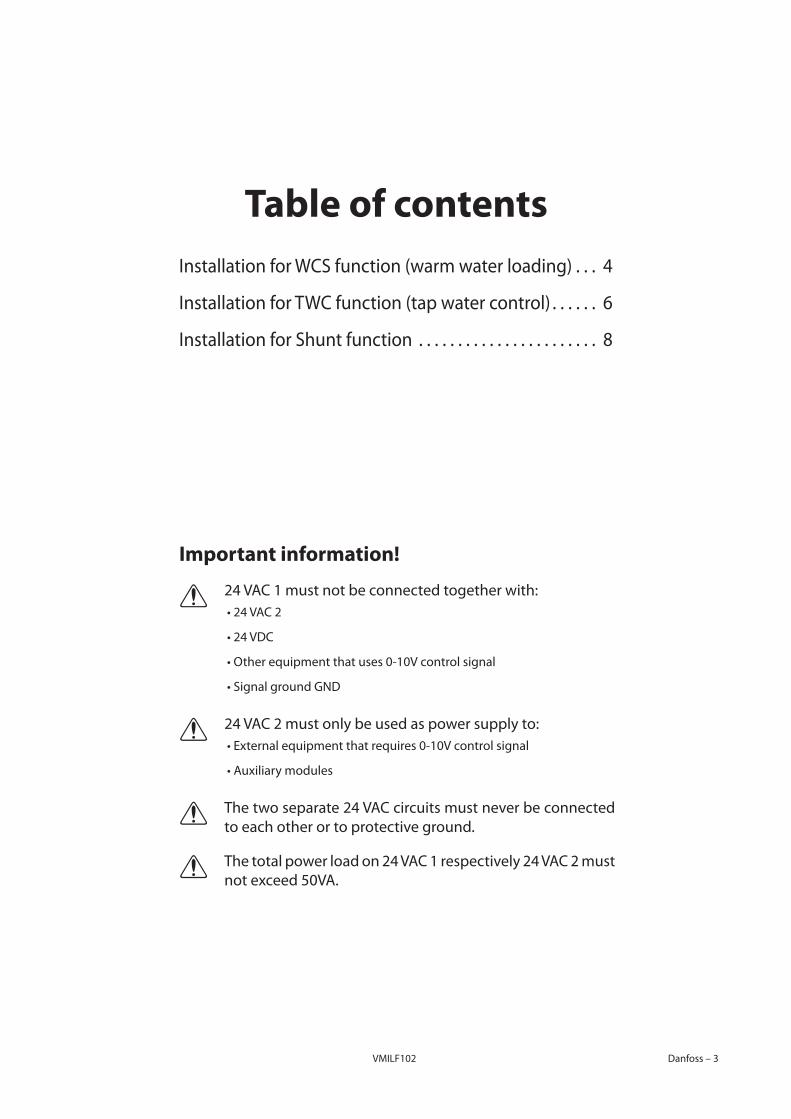
Important information!
24 VAC 1 must not be connected together with:⚠⚠ •24VAC2
•24VDC
•Otherequipmentthatuses0-10Vcontrolsignal
•SignalgroundGND
24 VAC 2 must only be used as power supply to:⚠⚠ •Externalequipmentthatrequires0-10Vcontrolsignal
•Auxiliarymodules
The two separate 24 VAC circuits must never be connected ⚠⚠to each other or to protective ground .
The total power load on 24 VAC 1 respectively 24 VAC 2 must ⚠⚠notexceed50VA.
VMILF1024 – Danfoss VMBQI102
Expansion module, HPC EMTheoperationaldescriptionfortheexpansionmoduleisavailableinthecontrollermanual.
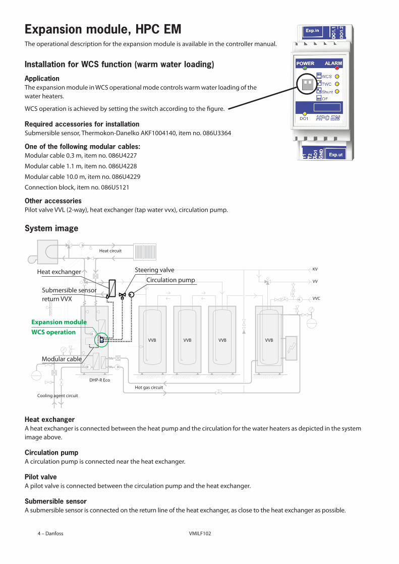
Installation for WCS function (warm water loading)
ApplicationTheexpansionmoduleinWCSoperationalmodecontrolswarmwaterloadingofthewater heaters .
WCS operation is achieved by setting the switch according to the figure .
Required accessories for installationSubmersiblesensor,Thermokon-DanelkoAKF1004140,itemno.086U3364
One of the following modular cables:Modularcable0.3m,itemno.086U4227
Modularcable1.1m,itemno.086U4228
Modularcable10.0m,itemno.086U4229
Connectionblock,itemno.086U5121
Other accessoriesPilotvalveVVL(2-way),heatexchanger(tapwatervvx),circulationpump.
System image
Heat exchangerAheatexchangerisconnectedbetweentheheatpumpandthecirculationforthewaterheatersasdepictedinthesystemimage above .
Circulation pumpAcirculationpumpisconnectedneartheheatexchanger.
Pilot valveApilotvalveisconnectedbetweenthecirculationpumpandtheheatexchanger.
Submersible sensorAsubmersiblesensorisconnectedonthereturnlineoftheheatexchanger,asclosetotheheatexchangeraspossible.
Heat circuit
Hot gas circuit
Cooling agent circuit
VVB VVB VVB VVB
Heatexchanger
Modular cable
Steering valve
Circulation pump
Expansion module
Wcs operation
Submersible sensorreturn VVX
KV
VV
VVC
DHP-R Eco
VMBQI102 VMILF102 Danfoss–5
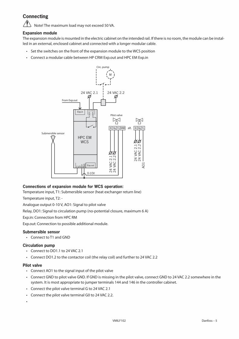
Connecting
⚠⚠⚠ Note!Themaximumloadmaynotexceed50VA.
Expansion moduleTheexpansionmoduleismountedintheelectriccabinetontheintendedrail.Ifthereisnoroom,themodulecanbeinstal-ledinanexternal,enclosedcabinetandconnectedwithalongermodularcable.
• SettheswitchesonthefrontoftheexpansionmoduletotheWCSposition
⚠• ConnectamodularcablebetweenHPCRMExp.outandHPCEMExp.in
Connections of expansion module for WCS operation:Temperatureinput,T1:Submersiblesensor(heatexchangerreturnline)
Temperatureinput,T2:-
Analogueoutput0-10V,AO1:Signaltopilotvalve
Relay,DO1:Signaltocirculationpump(no-potentialclosure,maximum6A)
Exp.in:ConnectionfromHPCRM
Exp.out:Connectiontopossibleadditionalmodule.
Submersible sensor⚠• ConnecttoT1andGND
Circulation pump⚠• ConnecttoDO1.1to24VAC2.1
⚠• ConnectDO1.2tothecontactorcoil(therelaycoil)andfurtherto24VAC2.2
Pilot valve⚠• ConnectAO1tothesignalinputofthepilotvalve
⚠• ConnectGNDtopilotvalveGND.IfGNDismissinginthepilotvalve,connectGNDto24VAC2.2somewhereinthesystem . It is most appropriate to jumper terminals 144 and 146 in the controller cabinet .
⚠• ConnectthepilotvalveterminalGto24VAC2.1
⚠• ConnectthepilotvalveterminalG0to24VAC2.2.
•
Exp.in
G GNDG0 Y1
Exp.out
DO1.
1
T1 T2 AO1
GND
DO1.
2
HPC EMWCS
24 VAC 2.1
24 V
AC 2
.1
24 VAC 2.2
24 V
AC 2
.2
M
alt. G G0 Y1
24 V
AC 2
.124
VAC
2.2
AO1
0-10V
Circ . pump
FromExp.out
Submersible sensor
Pilot valve
VMILF1026 – Danfoss VMBQI102
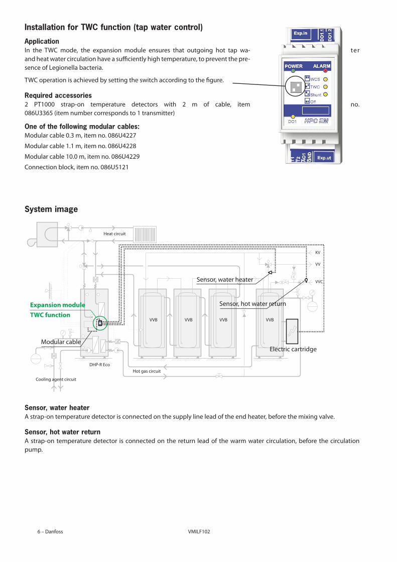
Installation for TWC function (tap water control)
ApplicationIn the TWC mode, the expansion module ensures that outgoing hot tap wa- ter and heat water circulation have a sufficiently high temperature, to prevent the pre-sence of Legionella bacteria .
TWC operation is achieved by setting the switch according to the figure .
Required accessories2 PT1000 strap-on temperature detectors with 2 m of cable, item no . 086U3365(itemnumbercorrespondsto1transmitter)
One of the following modular cables:Modularcable0.3m,itemno.086U4227
Modularcable1.1m,itemno.086U4228
Modularcable10.0m,itemno.086U4229
Connectionblock,itemno.086U5121
System image
Sensor, water heaterAstrap-ontemperaturedetectorisconnectedonthesupplylineleadoftheendheater,beforethemixingvalve.
Sensor, hot water returnAstrap-ontemperaturedetector isconnectedonthereturn leadof thewarmwatercirculation,beforethecirculationpump .
Heat circuit
Hot gas circuit
Cooling agent circuit
VVB VVB VVB VVB
Modular cable
Sensor, water heater
Electriccartridge
Sensor, hot water returnExpansion module
tWc function
KV
VV
VVC
DHP-R Eco
VMBQI102 VMILF102 Danfoss–7
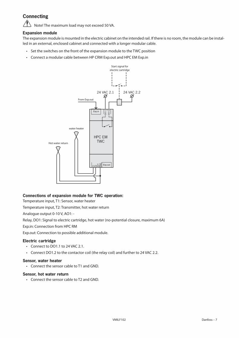
Connecting
⚠⚠⚠ Note!Themaximumloadmaynotexceed50VA.
Expansion moduleTheexpansionmoduleismountedintheelectriccabinetontheintendedrail.Ifthereisnoroom,themodulecanbeinstal-ledinanexternal,enclosedcabinetandconnectedwithalongermodularcable.
• SettheswitchesonthefrontoftheexpansionmoduletotheTWCposition
⚠• ConnectamodularcablebetweenHPCRMExp.outandHPCEMExp.in
Connections of expansion module for TWC operation:Temperature input, T1: Sensor, water heater
Temperature input, T2: Transmitter, hot water return
Analogueoutput0-10V,AO1:-
Relay,DO1:Signaltoelectriccartridge,hotwater(no-potentialclosure,maximum6A)
Exp.in:ConnectionfromHPCRM
Exp.out:Connectiontopossibleadditionalmodule.
Electric cartridge⚠• ConnecttoDO1.1to24VAC2.1.
⚠• ConnectDO1.2tothecontactorcoil(therelaycoil)andfurtherto24VAC2.2.
Sensor, water heater⚠• ConnectthesensorcabletoT1andGND.
Sensor, hot water return⚠• ConnectthesensorcabletoT2andGND.
Exp.in
Exp.out
DO1.
1
T1 T2 AO1
GND
DO1.
2
HPC EMTWC
24 VAC 2.1 24 VAC 2.2
Start signal for electric cartridge
water heater
Hot water return
FromExp.out
VMILF1028 – Danfoss VMBQI102
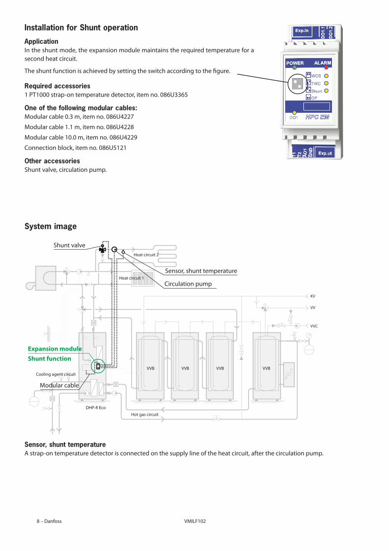
Installation for Shunt operation
ApplicationIntheshuntmode,theexpansionmodulemaintainstherequiredtemperatureforasecond heat circuit .
The shunt function is achieved by setting the switch according to the figure .
Required accessories1PT1000strap-ontemperaturedetector,itemno.086U3365
One of the following modular cables:Modularcable0.3m,itemno.086U4227
Modularcable1.1m,itemno.086U4228
Modularcable10.0m,itemno.086U4229
Connectionblock,itemno.086U5121
Other accessoriesShunt valve, circulation pump .
System image
Sensor, shunt temperatureAstrap-ontemperaturedetectorisconnectedonthesupplylineoftheheatcircuit,afterthecirculationpump.
Heat circuit 1
Heat circuit 2
Hot gas circuit
Cooling agent circuitVVB VVB VVB VVB
Shunt valve
Sensor, shunt temperature
Circulation pump
Modular cable
Expansion module
shunt function
KV
VV
VVC
DHP-R Eco
VMBQI102 VMILF102 Danfoss–9
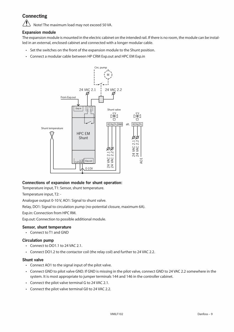
Connecting
⚠⚠⚠ Note!Themaximumloadmaynotexceed50VA.
Expansion moduleTheexpansionmoduleismountedintheelectriccabinetontheintendedrail.Ifthereisnoroom,themodulecanbeinstal-ledinanexternal,enclosedcabinetandconnectedwithalongermodularcable.
• SettheswitchesonthefrontoftheexpansionmoduletotheShuntposition.
⚠• ConnectamodularcablebetweenHPCRMExp.outandHPCEMExp.in
Connections of expansion module for shunt operation:Temperature input, T1: Sensor, shunt temperature .
Temperatureinput,T2:-
Analogueoutput0-10V,AO1:Signaltoshuntvalve.
Relay,DO1:Signaltocirculationpump(no-potentialclosure,maximum6A).
Exp.in:ConnectionfromHPCRM.
Exp.out:Connectiontopossibleadditionalmodule.
Sensor, shunt temperature⚠• ConnecttoT1andGND
Circulation pump⚠• ConnecttoDO1.1to24VAC2.1.
⚠• ConnectDO1.2tothecontactorcoil(therelaycoil)andfurtherto24VAC2.2.
Shunt valve⚠• ConnectAO1tothesignalinputofthepilotvalve.
⚠• ConnectGNDtopilotvalveGND.IfGNDismissinginthepilotvalve,connectGNDto24VAC2.2somewhereinthesystem . It is most appropriate to jumper terminals 144 and 146 in the controller cabinet .
⚠• ConnectthepilotvalveterminalGto24VAC2.1.
⚠• ConnectthepilotvalveterminalG0to24VAC2.2.
Exp.in
G GNDG0 Y1
Exp.out
DO1.
1
T1 T2 AO1
GND
DO1.
2
HPC EMShunt
24 VAC 2.1
24 V
AC 2
.1
24 VAC 2.2
24 V
AC 2
.2
0-10V
alt.
M
G G0 Y1
24 V
AC 2
.124
VAC
2.2
AO1
Circ . pump
FromExp.out
Shunt temperature
Shunt valve
VMILF10210 – Danfoss VMBQI102
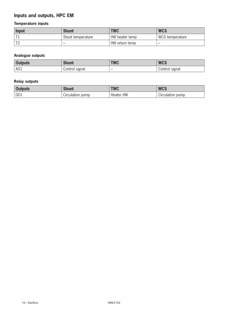
Inputs and outputs, HPC EM
Temperature inputs
Input Shunt TWC WCST1 Shunt temperature HW heater temp WCS temperatureT2 – HW return temp –
Analogue outputs
Outputs Shunt TWC WCSAO1 Control signal – Control signal
Relay outputs
Outputs Shunt TWC WCSDO1 Circulation pump Heater HW Circulation pump
VMBQI102 VMILF102 Danfoss – 11
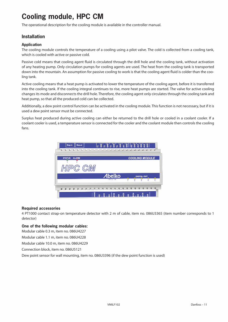
Cooling module, HPC CMThe operational description for the cooling module is available in the controller manual .
Installation
ApplicationThe cooling module controls the temperature of a cooling using a pilot valve . The cold is collected from a cooling tank, which is cooled with active or passive cold .
Passive cold means that cooling agent fluid is circulated through the drill hole and the cooling tank, without activation ofanyheatingpump.Onlycirculationpumpsforcoolingagentsareused.Theheatfromthecoolingtankistransporteddown into the mountain . An assumption for passive cooling to work is that the cooling agent fluid is colder than the coo-ling tank .
Active cooling means that a heat pump is activated to lower the temperature of the cooling agent, before it is transferred into the cooling tank . If the cooling integral continues to rise, more heat pumps are started . The valve for active cooling changes its mode and disconnects the drill hole . Therefore, the cooling agent only circulates through the cooling tank and heat pump, so that all the produced cold can be collected .
Additionally, a dew point control function can be activated in the cooling module . This function is not necessary, but if it is used a dew point sensor must be connected .
Surplus heat produced during active cooling can either be returned to the drill hole or cooled in a coolant cooler . If a coolant cooler is used, a temperature sensor is connected for the cooler and the coolant module then controls the cooling fans .
Required accessories 4PT1000contactstrap-ontemperaturedetectorwith2mofcable,itemno.086U3365(itemnumbercorrespondsto1detector)
One of the following modular cables:Modularcable0.3m,itemno.086U4227
Modularcable1.1m,itemno.086U4228
Modularcable10.0m,itemno.086U4229
Connectionblock,itemno.086U5121
Dewpointsensorforwallmounting,itemno.086U3396(ifthedewpointfunctionisused)
VMILF10212 – Danfoss VMBQI102
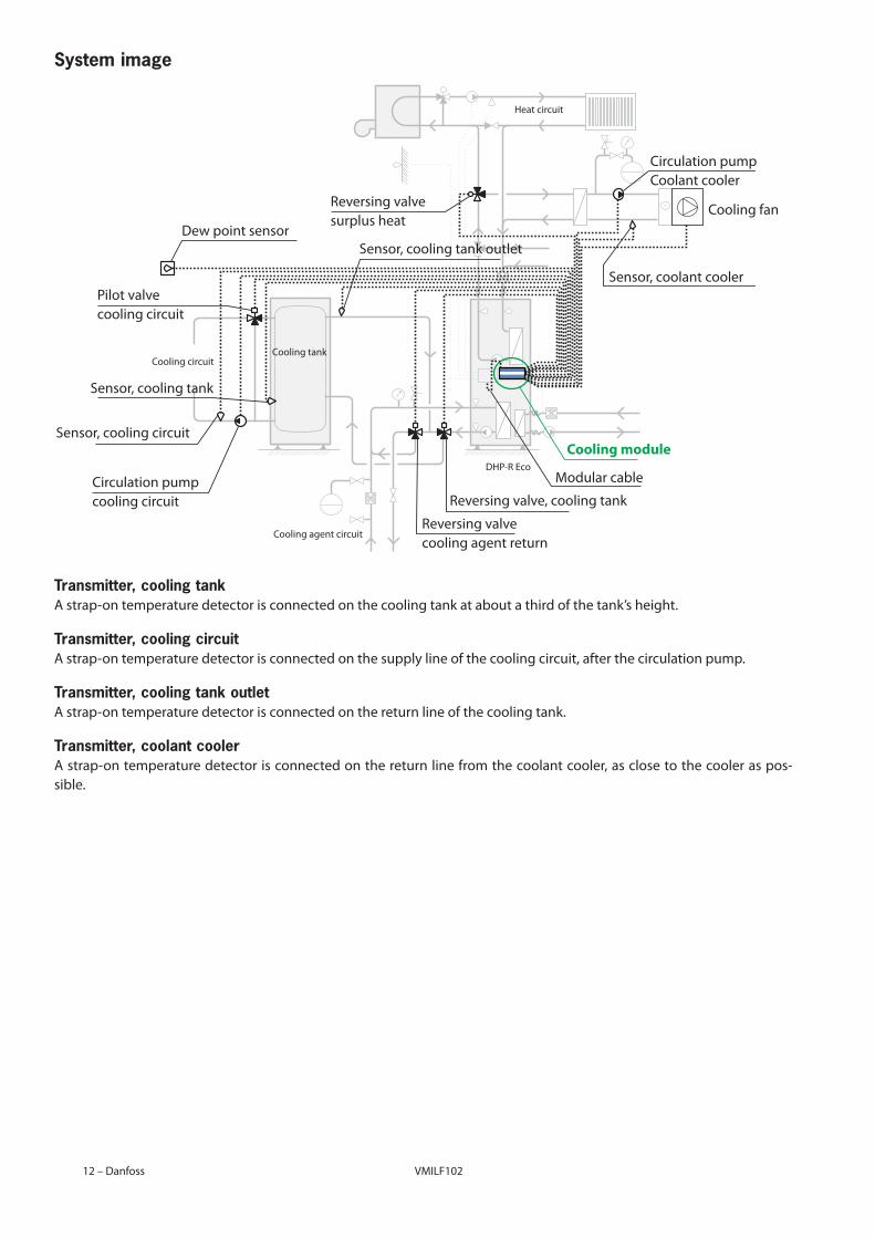
System image
Transmitter, cooling tankAstrap-ontemperaturedetectorisconnectedonthecoolingtankataboutathirdofthetank’sheight.
Transmitter, cooling circuitAstrap-ontemperaturedetectorisconnectedonthesupplylineofthecoolingcircuit,afterthecirculationpump.
Transmitter, cooling tank outletAstrap-ontemperaturedetectorisconnectedonthereturnlineofthecoolingtank.
Transmitter, coolant coolerAstrap-ontemperaturedetectorisconnectedonthereturnlinefromthecoolantcooler,asclosetothecooleraspos-sible .
Heat circuit
Cooling agent circuit
Cooling circuitCooling tank
DHP-R EcoModular cable
Cooling fan
Sensor, coolant cooler
Sensor, cooling tank outlet
Sensor, cooling tank
Dew point sensor
Sensor, cooling circuit
Circulation pumpCoolant cooler
Circulation pumpcooling circuit
Pilot valvecooling circuit
Reversingvalve,coolingtank
Reversingvalvecooling agent return
Reversingvalvesurplus heat
cooling module
VMBQI102 VMILF102 Danfoss – 13
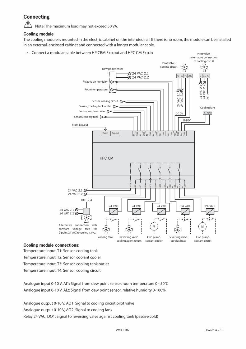
Connecting
⚠⚠⚠ Note!Themaximumloadmaynotexceed50VA.
Cooling moduleThe cooling module is mounted in the electric cabinet on the intended rail . If there is no room, the module can be installed inanexternal,enclosedcabinetandconnectedwithalongermodularcable.
⚠• ConnectamodularcablebetweenHPCRMExp.outandHPCCMExp.in
Cooling module connections:Temperature input, T1: Sensor, cooling tank
Temperature input, T2: Sensor, coolant cooler
Temperature input, T3: Sensor, cooling tank outlet
Temperature input, T4: Sensor, cooling circuit
Analogueinput0-10V,AI1:Signalfromdewpointsensor,roomtemperature0-50°C
Analogueinput0-10V,AI2:Signalfromdewpointsensor,relativehumidity0-100%
Analogueoutput0-10V,AO1:Signaltocoolingcircuitpilotvalve
Analogueoutput0-10V,AO2:Signaltocoolingfans
Relay24VAC,DO1:Signaltoreversingvalveagainstcoolingtank(passivecold)
Exp.in Exp.out
G GNDG0 Y1
DO1
G0
G0
DO2
G0
DO3
G0
DO4
G0
DO5
G0
24VA
C
T1 AO1
AI2
GND
T2 GND
T3 GND
T4 GND
AI1
GND
GND
GND
AO2
GND
HPC CM
24 VAC
0-10V
0-10V
M
24 VAC
M
24 VAC24 VAC 24 VAC
24 V
AC 2
.124
VAC
2.2
24 VAC 2.124 VAC 2.2
G G0 Y1
GNDY1
24 VAC 2.1
24 V
AC 2
.124
VAC
2.2
AO1
24 VAC 2.2
24 VAC 2.1
DO1,2,4
24 VAC 2.2
Pilot valve, cooling circuit
Pilot valve, alternative connection
of cooling circuit
Circ . pump, coolant cooler
Reversingvalve,surplus heat
Reversingvalve, cooling agent return
cooling tank
Alternative connection with constant voltage feed for 2-point24VACreversingvalve.
Circ . pump, coolant circuit
Dew point sensor
Cooling fans
FromExp.out
Sensor, cooling tank
Sensor, surplus cooler
Sensor, cooling tank outlet
Sensor, cooling circuit
Roomtemperature
Relativeairhumidity
VMILF10214 – Danfoss VMBQI102
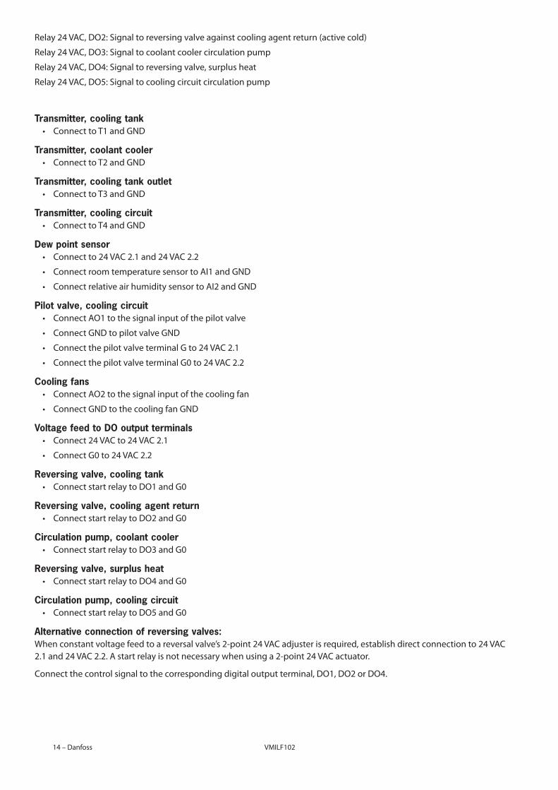
Relay24VAC,DO2:Signaltoreversingvalveagainstcoolingagentreturn(activecold)
Relay24VAC,DO3:Signaltocoolantcoolercirculationpump
Relay24VAC,DO4:Signaltoreversingvalve,surplusheat
Relay24VAC,DO5:Signaltocoolingcircuitcirculationpump
Transmitter, cooling tank⚠• ConnecttoT1andGND
Transmitter, coolant cooler⚠• ConnecttoT2andGND
Transmitter, cooling tank outlet⚠• ConnecttoT3andGND
Transmitter, cooling circuit⚠• ConnecttoT4andGND
Dew point sensor⚠• Connect to 24 VAC 2 .1 and 24 VAC 2 .2
⚠• ConnectroomtemperaturesensortoAI1andGND
⚠• ConnectrelativeairhumiditysensortoAI2andGND
Pilot valve, cooling circuit⚠• ConnectAO1tothesignalinputofthepilotvalve
⚠• ConnectGNDtopilotvalveGND
⚠• ConnectthepilotvalveterminalGto24VAC2.1
⚠• ConnectthepilotvalveterminalG0to24VAC2.2
Cooling fans⚠• ConnectAO2tothesignalinputofthecoolingfan
⚠• ConnectGNDtothecoolingfanGND
Voltage feed to DO output terminals⚠• Connect 24 VAC to 24 VAC 2 .1
⚠• ConnectG0to24VAC2.2
Reversing valve, cooling tank⚠• ConnectstartrelaytoDO1andG0
Reversing valve, cooling agent return⚠• ConnectstartrelaytoDO2andG0
Circulation pump, coolant cooler⚠• ConnectstartrelaytoDO3andG0
Reversing valve, surplus heat⚠• ConnectstartrelaytoDO4andG0
Circulation pump, cooling circuit⚠• ConnectstartrelaytoDO5andG0
Alternative connection of reversing valves:Whenconstantvoltagefeedtoareversalvalve’s2-point24VACadjusterisrequired,establishdirectconnectionto24VAC2.1and24VAC2.2.Astartrelayisnotnecessarywhenusinga2-point24VACactuator.
Connectthecontrolsignaltothecorrespondingdigitaloutputterminal,DO1,DO2orDO4.
VMBQI102 VMILF102 Danfoss–15
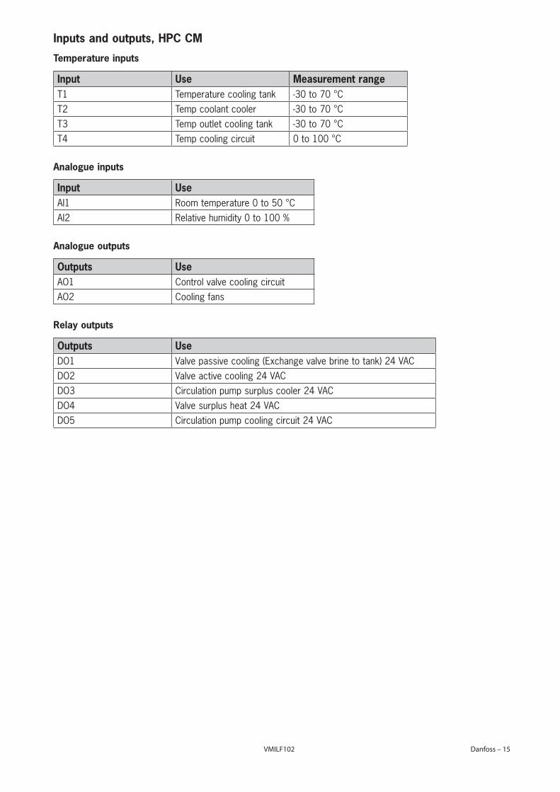
Inputs and outputs, HPC CM
Temperature inputs
Input Use Measurement rangeT1 Temperature cooling tank -30 to 70 °CT2 Temp coolant cooler -30 to 70 °CT3 Temp outlet cooling tank -30 to 70 °CT4 Temp cooling circuit 0 to 100 °C
Analogue inputs
Input UseAI1 Room temperature 0 to 50 °CAI2 Relative humidity 0 to 100 %
Analogue outputs
Outputs UseAO1 Control valve cooling circuitAO2 Cooling fans
Relay outputs
Outputs UseDO1 Valve passive cooling (Exchange valve brine to tank) 24 VACDO2 Valve active cooling 24 VACDO3 Circulation pump surplus cooler 24 VACDO4 Valve surplus heat 24 VACDO5 Circulation pump cooling circuit 24 VAC

VMILF102