di-plot user english - digital information automatic mode front / back mode scenario on cip3 input...
TRANSCRIPT

DI-Plot
Instructions manual

Digital Information Ltd. Technoparkstrasse 1 CH-8005 Zürich
© Copyright by Digital Information Ltd. 2006
The copyright for this technical documentation remains with Digital Information Ltd.
All rights, including reproduction and distribution rights as well as translation rights, are reserved. No part of the documentation may be reproduced in any form (printing, photocopying, microfilm or other process) without written per mission, nor may it be stored, processed, reproduced or distributed using electronic systems.
Every misuse is punishable and requires restitution of damages.
Identifier Instructions manual - EN
Target group User
Product DI-Plot
Version V5.10
Article code DI-Plot HB03-009 EN

Table of contents
DI-Plot – Instructions manual I
DI-
Plo
t HB
03-0
09 E
N
Table of contents
1 Semi Automatic Mode ................................................................................................... 1-1 1.1 The user interface............................................................................................................................. 1-1
1.1.1 Job list .............................................................................................................................. 1-2 1.1.2 Sorting jobs by date/time or name.................................................................................... 1-2 1.1.3 Searching jobs.................................................................................................................. 1-3 1.1.4 Refreshing the job list........................................................................................................ 1-3 1.1.5 Adding jobs to the queue list............................................................................................. 1-3
1.2 Front / Back mode scenario on CIP3 Input – JDF Output................................................................. 1-4 1.2.1 Scenario 1 – Front/Back mode enabled – CIP3 with Front/Back....................................... 1-5 1.2.2 Scenario 2 – Front/Back mode enabled – CIP3 single sided............................................. 1-6 1.2.3 Adding jobs to the queue list – Front/Back mode disabled ............................................... 1-7
1.3 Converting a selected job................................................................................................................. 1-7 1.3.1 No success in converting.................................................................................................. 1-8 1.3.2 Reloading the source directory ......................................................................................... 1-8
1.4 Missing spot colors .......................................................................................................................... 1-8 1.4.1 Setting the software’s reaction to missing spot colors....................................................... 1-9
1.5 Changing the source directory ......................................................................................................... 1-9 1.6 Where are the files stored after converting to CIP4/JDF or Inkzone formats? ................................. 1-10 1.7 Where are the files stored after converting to formats other than CIP4 or Inkzone?........................ 1-11 1.8 Combining jobs in 1 Bit or 8 Bit TIFF format ................................................................................... 1-12
2 Hotfolder Mode ........................................................................................................... 2-1 2.1 The user interface............................................................................................................................. 2-1 2.2 Start the hotfolder ............................................................................................................................ 2-1 2.3 Starting the hotfolder mode automatically ........................................................................................ 2-2 2.4 Quitting the hotfolder mode.............................................................................................................. 2-2 2.5 Stopping a conversion in hotfolder mode ......................................................................................... 2-3 2.6 Changing the start time and timing................................................................................................... 2-3
3 Spot Color Editor ......................................................................................................... 3-1 3.1 Selecting a spot color....................................................................................................................... 3-1 3.2 Using the spot color editor ............................................................................................................... 3-1
3.2.1 Overview........................................................................................................................... 3-2 3.2.2 Adding a spot color .......................................................................................................... 3-2 3.2.3 Changing a spot color ...................................................................................................... 3-2 3.2.4 Deleting a color................................................................................................................. 3-3


Semi Automatic ModeThe user interface 1
DI-Plot – Instructions manual 1-1
DI-
Plo
t HB
03-0
09 E
N
1 Semi Automatic Mode
The semi automatic mode offers greater flexibility in selecting one or multiple jobs from the input directory for conversion. The selected jobs are converted to the target format and then copied to the destination directory, or sent directly to the attached printer.
1.1 The user interface
Activate the semi automatic mode by opening this entry.
1

1 Semi Automatic Mode The user interface
1-2 DI-Plot – Instructions manual
DI-
Plo
t HB
03-0
09 E
N
The user interface is divided into three main sections:
(1) Job list area: all jobs from the source directory are displayed here.
(2) Queued job area: all jobs selected manually are displayed in this section. These jobs are ready for conversion.
(3) Converted job area: all finished jobs are listed here.
1.1.1 Job list
Following information is displayed in the job list:
(1) Job name
(2) Colors
(3) Input path and source directory
(4) Input and output formats
Spot color handling: The software can support up to 12 spot colors. Each spot color is displayed with a number, starting from 1.
Example 1
A job with CMYK plus the spot colors HKS1 and CocaColaRed would look like this: CMYK12
Example 2
A job containing Black plus the spot colors HKS15, CocaColaRed and RolexGold would look like this:
K123
1.1.2 Sorting jobs by date/time or name
The input data can be sorted with this button (1):
a) by ascending name
b) by descending name
c) by ascending date/time
d) by descending date/time
1
1 1
1
1
1
1
1

Semi Automatic ModeThe user interface 1
DI-Plot – Instructions manual 1-3
DI-
Plo
t HB
03-0
09 E
N
1.1.3 Searching jobs
Search a job by entering its name here (1). The job list will automatically update itself with the search results.
1.1.4 Refreshing the job list
When the counter (1) reaches 0, the job list will update itself automatically. Press this button (2) for updating the job list manually. The counter value can be defined in the software’s configuration section.
1.1.5 Adding jobs to the queue list
Jobs are selected from the job list (1) by clicking on them once with the left mouse button. They will appear in the job queue (2) and remain displayed in the job list (1). Remove them from the job queue (2) by clicking on them again with the left mouse button. When adding a job to the job queue (2), detailed information is given in the space below (3): the job’s dimension in pixels, in millimeters or inches, its resolution in dpi, and the number of color separations.
1
1
1
1
11
1 Semi Automatic Mode Front / Back mode scenario on CIP3 Input – JDF Output
1-4 DI-Plot – Instructions manual
DI-
Plo
t HB
03-0
09 E
N
CIP3 CIP3
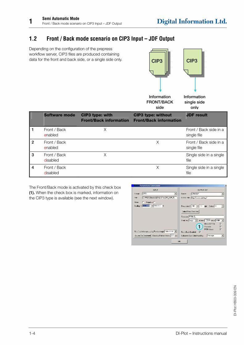
1.2 Front / Back mode scenario on CIP3 Input – JDF Output
Depending on the configuration of the prepress workflow server, CIP3 files are produced containing data for the front and back side, or a single side only.
Software mode
CIP3 type: with Front/Back information
CIP3 type: without Front/Back information
JDF result
1 Front / Back enabled
X Front / Back side in a single file
2 Front / Back enabled
X Front / Back side in a single file
3 Front / Back disabled
X Single side in a single file
4 Front / Back disabled
X Single side in a single file
The Front/Back mode is activated by this check box (1). When the check box is marked, information on the CIP3 type is available (see the next window).
Information FRONT/BACK
side
Information single side
only
1
CIP3 CIP3

Semi Automatic ModeFront / Back mode scenario on CIP3 Input – JDF Output 1
DI-Plot – Instructions manual 1-5
DI-
Plo
t HB
03-0
09 E
N
In the job list, a CIP3 type identification code is displayed at the end of each job name (2) + (3).
Indicator
D Information on Front / Back is available
(2)
S Information on Front / Back is not available
(3)
In the job queue, a job side indicator (4) shows up at the beginning of each job name:
Indicator
DF / Df Double sided Front (4)
DB / Db Double sided Back
sF / sf Single Front
sB / sb Single Back
1.2.1 Scenario 1 – Front/Back mode enabled – CIP3 with Front/Back
Each CIP3 job containing a front and back side is displayed as one job in the job list (1): the D indicator (3) attached to the end of its name.
When a job is added to the job queue, the front side and back sides appear as separate jobs (2): the front side is indicated as DF, the back side as DB (4).
The software will produce one combined JDF file containing front and back.
1
1
1
1
1
1
1

1 Semi Automatic Mode Front / Back mode scenario on CIP3 Input – JDF Output
1-6 DI-Plot – Instructions manual
DI-
Plo
t HB
03-0
09 E
N
1.2.2 Scenario 2 – Front/Back mode enabled – CIP3 single sided
All CIP3 jobs are displayed in the job list (1). If a job contains a single side only, the S indicator is attached to the end of the job name (3).
When a single sided job is added to the job queue (2), it will be indicated as DF (4) in the front of its name.
When the back of a job (4) shows up in the job list on its own, click on it to add it to the job queue. It will automatically be marked with DB (5).
The software alternates between DF / DB when importing single jobs to the job queue.
When a job (4) shall be processed as single sided, click on it with the right mouse button (6). The DF marker will change to sF. For changing back to the DF indicator, click on it with the right mouse button several times until DF shows up again.
1
11
1
1
1
1
1

Semi Automatic ModeConverting a selected job 1
DI-Plot – Instructions manual 1-7
DI-
Plo
t HB
03-0
09 E
N
1.2.3 Adding jobs to the queue list – Front/Back mode disabled
If the Front/Back mode in the setup is disabled, the software will create output files without any indication of which is the front or back side.
A CIP3 job containing both a front and back side is thus displayed as two jobs. The appropriate “_Front” or “_Back” indicators are attached to their names (1).
If there is no information available if a single sided job is a front or back side, the job will be display without a side indicator (2).
Click on a job in the job list to add it to the queue list. The indicators (1) and (2) will inform if the job is Front/Back or Single Side.
Note It is recommended to disable the Front/Back mode if the prepress workflow produces single sided CIP3 files only.
1.3 Converting a selected job
When jobs are selected from the job list (1), they are instantly available in the queue list (2). Click on this button (3) to start the conversion. A progress bar will show up. All finished jobs will appear in the converted job list (4).
To abort a running conversion, press this button (5).
1
1
1 1
1
1
1
1
1

1 Semi Automatic Mode Missing spot colors
1-8 DI-Plot – Instructions manual
DI-
Plo
t HB
03-0
09 E
N
1.3.1 No success in converting
If the user aborts a job conversion, or when a problem has occurred during processing, the “-” indicator (1) is attached to the front of the job’s name in the converted jobs list.
1.3.2 Reloading the source directory
To update the job list manually with the source directory’s content, select the “Refresh” button (1).
Note: the software will update the job list automatically when the timer (2) has reached 0.
1.4 Missing spot colors
The software can be configured so that the user is informed when spot colors are missing.
When such a job is selected from the job list, an alert window will come up (1).
Press this button (2) to continue.
You can either add the missing spot color to the spot color table or start the conversion without.
If converting the job without the missing spot color, the CMYK values of the so-called “DefaultColor” will be used instead.
1
11
1
1
Semi Automatic ModeChanging the source directory 1
DI-Plot – Instructions manual 1-9
DI-
Plo
t HB
03-0
09 E
N
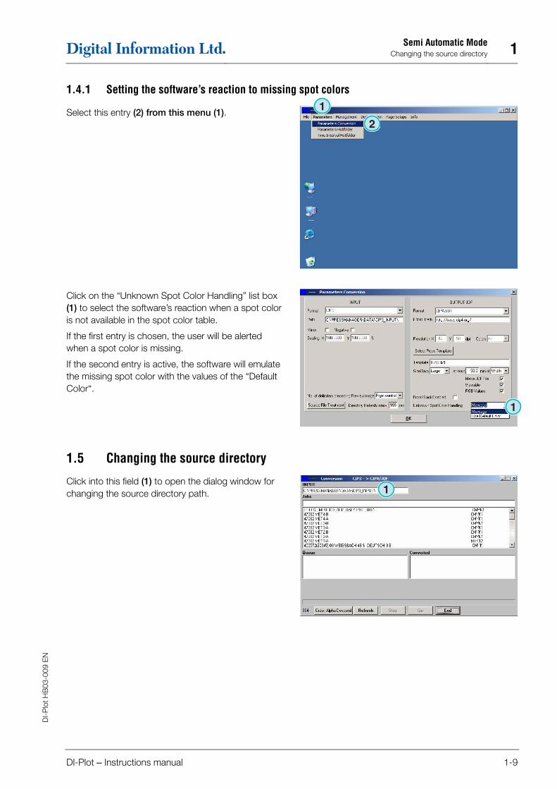
1.4.1 Setting the software’s reaction to missing spot colors
Select this entry (2) from this menu (1).
Click on the “Unknown Spot Color Handling” list box (1) to select the software’s reaction when a spot color is not available in the spot color table.
If the first entry is chosen, the user will be alerted when a spot color is missing.
If the second entry is active, the software will emulate the missing spot color with the values of the “Default Color“.
1.5 Changing the source directory
Click into this field (1) to open the dialog window for changing the source directory path.
1
1
11
1

1 Semi Automatic Mode Where are the files stored after converting to CIP4/JDF or Inkzone formats?
1-10 DI-Plot – Instructions manual
DI-
Plo
t HB
03-0
09 E
N
Select the source directory here (1).
1.6 Where are the files stored after converting to CIP4/JDF or Inkzone formats?
If the software is set to convert the input files to the CIP4/JDF or Inkzone format, the destination path can be chosen in the Press/Inkzone template. In order to do so, open this menu (1) and select the first entry (2).
Open the Press/Inkzone template by clicking on its button (1).
1
1
1
1

Semi Automatic ModeWhere are the files stored after converting to formats other than CIP4 or Inkzone? 1
DI-Plot – Instructions manual 1-11
DI-
Plo
t HB
03-0
09 E
N
The destination directory for the converted files is selected here (1). Click on the current path (1) to change this directory.
A new dialog window (2) will open where the path can be selected.
1.7 Where are the files stored after converting to formats other than CIP4 or Inkzone?
If the software is set to convert the input files to a format other than CIP4/JDF or Inkzone, the destination path is set directly in the software configuration window. To view the destination path, open this menu (1) and select the first entry (2).
1
1
1
1

1 Semi Automatic Mode Combining jobs in 1 Bit or 8 Bit TIFF format
1-12 DI-Plot – Instructions manual
DI-
Plo
t HB
03-0
09 E
N
The destination path is set here (1). Change it by clicking into the current path (1).
A new dialog window (2) will open where the path can be selected
1.8 Combining jobs in 1 Bit or 8 Bit TIFF format
The software offers the possibility to combine separations from two different jobs into one job. This feature is mainly used when a product is printed in different languages. The varying black plates carrying the different language versions can be combined with the corresponding CMY plates.
Press “Shift” on the keyboard and select a job from the job list (1).
1
1
1

Semi Automatic ModeCombining jobs in 1 Bit or 8 Bit TIFF format 1
DI-Plot – Instructions manual 1-13
DI-
Plo
t HB
03-0
09 E
N
The selected job will show up (3) in a new control panel (2). The job’s color separations (4) are listed in the lower left area.
Select the second job used for combination (1). Its separations show up in the lower right area (2).
Select the separations from the separation lists of the two jobs shown at (1) and (2). Press this button (3) to save the current combination to the queue list. If necessary, add an additional combination by selecting the separations you need. Press here for closing the control panel (4).
All combinations show up in the queue list (1). Start the conversion with this button (2).
1
1
1
1
1
1 1
1 1
1
1


Hotfolder ModeThe user interface 2
DI-Plot – Instructions manual 2-1
DI-
Plo
t HB
03-0
09 E
N
2 Hotfolder Mode
2.1 The user interface
Activate the fully automatic hotfolder mode from this menu (1).
The user interface is divided into four main sections:
(1) The job in progress
(2) Upcoming jobs
(3) Finished jobs
(4) The progress bar / hotfolder indicator
2.2 Start the hotfolder
Activate the hotfolder mode by clicking on this check box (1).
1
1
1
1
1
1

2 Hotfolder Mode Starting the hotfolder mode automatically
2-2 DI-Plot – Instructions manual
DI-
Plo
t HB
03-0
09 E
N
When the hotfolder mode is active, the indicator (1) moves constantly back and forth. All jobs younger by date and time than the start time (2) will be converted automatically.
2.3 Starting the hotfolder mode automatically
By marking this check box (1) the software will go directly into hotfolder mode when being launched.
2.4 Quitting the hotfolder mode
Deactivate the automatic hotfolder mode by disabling this check box (1). Leave the hotfolder mode by pressing this button (2).
1
1
1
1 1

Hotfolder ModeStopping a conversion in hotfolder mode 2
DI-Plot – Instructions manual 2-3
DI-
Plo
t HB
03-0
09 E
N
2.5 Stopping a conversion in hotfolder mode
Press this button (1) for aborting a conversion.
2.6 Changing the start time and timing
To change the start time, open this menu (1) and select the third entry (2). The corresponding window will open (see the next illustration (3).
Set the start time and date here (4). By setting a time lapse (5) the software will start processing the youngest job with a delay. This prevents that the conversion starts before the job is fully transmitted by the prepress workflow server.
Note on 1 Bit TIFF input:
Increase the Time Lapse value (5) to make sure that all 1 Bit TIFF separations will be used in conversion.
1
1
1
1
1
1


Spot Color EditorSelecting a spot color 3
DI-Plot – Instructions manual 3-1
DI-
Plo
t HB
03-0
09 E
N
3 Spot Color Editor
3.1 Selecting a spot color
From the third menu (1) open this window (2).
The program directory is the standard location for the Spot Color Table file.
If you are running multiple instances of the software, it is recommended to use one spot color table for all installed copies. Select the Spot Color Table in the dialog window (1).
3.2 Using the spot color editor
From this menu (1) open the Spot Color Editor (2).
1
1
1
1
1

3 Spot Color Editor Using the spot color editor
3-2 DI-Plot – Instructions manual
DI-
Plo
t HB
03-0
09 E
N
3.2.1 Overview
The title bar of the Spot Color Editor window displays the path to the Spot Color Table (1).
The table contains around 8000 colors. Each spot color has its CMYK values for emulation (2).
3.2.2 Adding a spot color
To add a new spot color, enter its name and values here (1) then press this button (2).
3.2.3 Changing a spot color
To change a spot color, select it from the Spot Color Table list (1). Change its name or its CMYK values or both here (2). Then press this button (3) to save it.
1
1
1
1
1
1
1

Spot Color EditorUsing the spot color editor 3
DI-Plot – Instructions manual 3-3
DI-
Plo
t HB
03-0
09 E
N
3.2.4 Deleting a color
To delete a color entry, select it from the list (1) and press this button (2).
1
1