diagnosis of electrical performance and aging behavior of ... · power factor test or tan delta...
TRANSCRIPT
Diagnosis of Electrical Performance
and Aging Behavior of
Transformer Dielectrics
CIGRE Thailand
29th November 2013, Bangkok
Supatra A. Bhumiwat
Independent HV Diagnostics Consultant
www.kea-consultant.com

2
Agenda
• The Nature of Electrical Insulation or Dielectrics
• Classification of problems in transformer dielectrics
• Identification of aging in transformer dielectrics by
oil analysis
• Identification of aging in transformer dielectrics by
electrical tests
3
The Nature of Electrical Insulation
Electrical Insulation is sometimes called
“Dielectrics”
due to its 2 basic electrical properties:
• Ability to persist in electrostatic field for a long time
(High Resistance or Low Conduction)
• Ability to be polarized
(Polarization)
“Conduction” and “Polarization” Phenomena
occur in every dielectric material, more or less.
4
Polarization
“Every kind of insulating materials consists, at an
atomic level, of negative and positive charges
balancing each other…..
As soon as a material is exposed to an electric field,
the positive and negative charges become oriented
thus forming different kinds of dipoles….”
From Walter S. Zaengl; “Dielectric spectroscopy in time and frequency domains for HV power
equipment, Part I: Theoretical Considerations”, IEEE Electrical Insulation Magazine,
vol. 19 no. 5, pp. 5-19, September/October 2003.

5
Polarization
Arrangement of charges during “Polarisation”
6
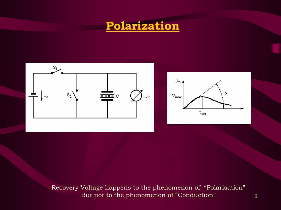
Polarization
Recovery Voltage happens to the phenomenon of “Polarisation”
But not to the phenomenon of “Conduction”
7
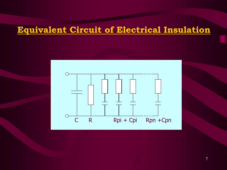
Equivalent Circuit of Electrical Insulation
C R Rpi + Cpi Rpn +Cpn

8
Polarization Conduction
1 The charges linked with
definite molecules of matter are
brought into motion. These
charges cannot leave the
confines of a given molecule.
1 The free charges (carriers) can
move through the entire thickness
of a dielectric from one electrode
to the other.
2 “Polarization” takes place in all
the molecules of a dielectric
and causes chemical change or
deterioration
2 “Conduction” is often determined
by the presence of impurities or
contaminants. It is not attributed
to its basic substance
3 When the voltage applied to a
dielectric is discontinued, the
displaced charges may tend to
return to their initial positions
3 The return (or recovery) voltage
never happens to the phenomenon
of electrical conduction.
4 The absorption current due to
polarization decays to zero
slowly under a direct voltage.
4 The conduction current exists and
keeps constant so long as a direct
voltage is applied to a dielectric.
From B. Tareev “Physics of Dielectric Materials”, MIR Publishers, Moscow, 1975

9
Each problem in a dielectric is produced by
the mechanism of
either “Conduction” or “Polarization” or both.
An ability to diagnose and identify
one from the other
allows problem in a dielectric
to be solved correctly.

10
Classification of problems
in Transformer Insulation
CLASSIFICATION OF PROBLEMS IN TRANSFORMER INSULATION
Polarization Conduction
Moisture in paper / pressboard Free water in oil
Oxidation by-products (acid & non-acid type) Surface humidity
Polar molecules in oil
(polar aromatics, polar compounds, etc)
Surface contaminants
Sludges at oil-paper interface Tracking
Thermal aging by-products Carbon dust
By products from Partial discharges Metal particles in oil
Arcing by-products Debris from fault
Corrosive products in oil Copper sulphide
11
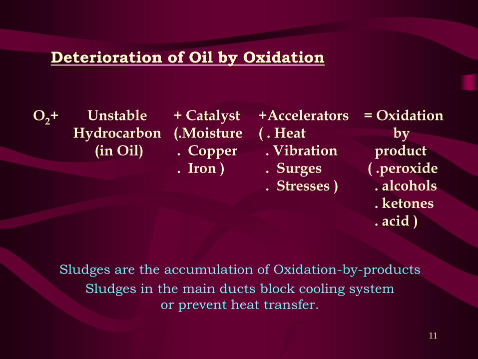
O2+ Unstable Hydrocarbon
(in Oil)
+ Catalyst(.Moisture. Copper. Iron )
+Accelerators( . Heat. Vibration. Surges. Stresses )
= Oxidationby
product ( .peroxide. alcohols. ketones. acid )
Deterioration of Oil by Oxidation
Sludges are the accumulation of Oxidation-by-products
Sludges in the main ducts block cooling system
or prevent heat transfer.
12
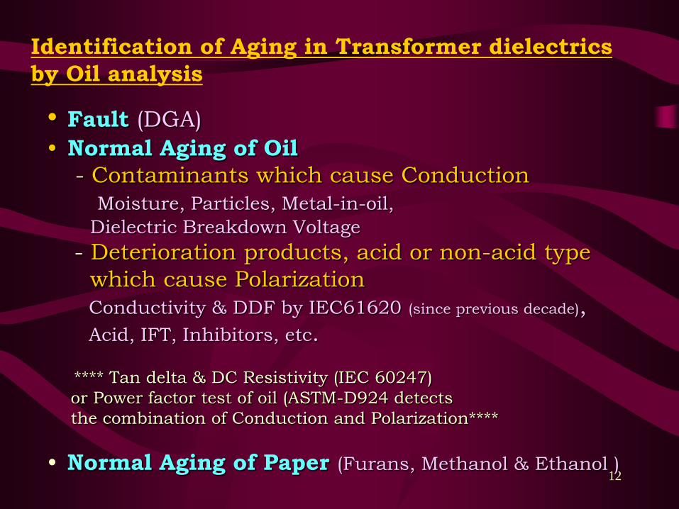
Identification of Aging in Transformer dielectrics
by Oil analysis
• Fault (DGA)
• Normal Aging of Oil
- Contaminants which cause Conduction
Moisture, Particles, Metal-in-oil,
Dielectric Breakdown Voltage
- Deterioration products, acid or non-acid type
which cause Polarization
Conductivity & DDF by IEC61620 (since previous decade),
Acid, IFT, Inhibitors, etc.
**** Tan delta & DC Resistivity (IEC 60247)
or Power factor test of oil (ASTM-D924 detects
the combination of Conduction and Polarization****
• Normal Aging of Paper (Furans, Methanol & Ethanol )

13
Performance of Oil
based on IEC61620
14
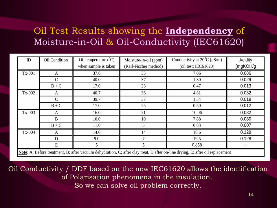
Oil Test Results showing the Independency of
Moisture-in-Oil & Oil-Conductivity (IEC61620)
ID Oil Condition Oil temperature (oC) Moisture-in-oil (ppm) Conductivity at 20
oC (pS/m) Acidity
when sample is taken (Karl-Fischer method) (oil test: IEC61620) (mgKOH/g
Tx-001 A 37.6 35 7.06 0.086
C 40.0 37 1.30 0.029
B + C 17.0 23 0.47 0.013
Tx-002 A 40.7 36 4.81 0.082
C 39.7 37 1.54 0.019
B + C 17.0 25 0.50 0.012
Tx-003 A 16.0 21 10.06 0.082
B 10.0 10 7.88 0.080
B + C 11.0 5 0.83 0.007
Tx-004 A 14.0 14 18.6 0.129
D 9.0 7 19.5 0.128
E 5 5 0.858 -
Note: A: Before treatment, B: after vacuum dehydration, C; after clay treat, D after on-line drying, E: after oil replacement
Oil Conductivity / DDF based on the new IEC61620 allows the identification
of Polarisation phenomena in the insulation.
So we can solve oil problem correctly.

15
Moisture-in-oil VS
Conductivity based on IEC61620
(Data from 1,207 oil samples)
Moisture VS Conductivity at 20oC
(Data from 1,207 oil samples)
1.E+00
1.E+01
1.E+02
1.E-02 1.E-01 1.E+00 1.E+01 1.E+02Conductivity (pS/m)
Mo
istu
re (
pp
m)

16
DDF (IEC60247) VS
Conductivity based on IEC61620
(Data from 1,066 oil samples)
DDF (60247) at 90oC VS Conductivity (61620) at 20
oC
(Data from 1,066 oil samples
1.E-03
1.E-02
1.E-01
1.E+00
1.E-01 1.E+00 1.E+01 1.E+02 1.E+03
s at 20oC (pS/m)
DD
F (
60
24
7)
at 9
0oC
17
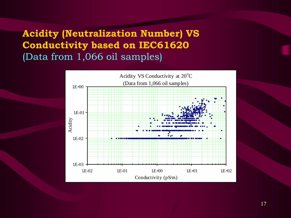
Acidity (Neutralization Number) VS
Conductivity based on IEC61620
(Data from 1,066 oil samples)
Acidity VS Conductivity at 20oC
(Data from 1,066 oil samples)
1.E-03
1.E-02
1.E-01
1.E+00
1.E-02 1.E-01 1.E+00 1.E+01 1.E+02
Conductivity (pS/m)
Aci
dit
y
18
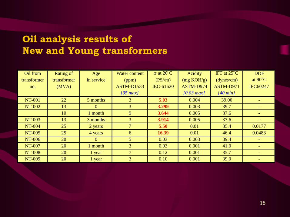
Oil analysis results of
New and Young transformers
Oil from Rating of Age Water content s at 20oC Acidity IFT at 25
oC DDF
transformer transformer in service (ppm) (PS//m) (mg KOH/g) (dynes/cm) at 90oC
no. (MVA) ASTM-D1533 IEC-61620 ASTM-D974 ASTM-D971 IEC60247
[35 max] [0.03 max] [40 min]
NT-001 22 5 months 3 5.03 0.004 39.00 -
NT-002 13 0 3 3.299 0.003 39.7 -
10 1 month 9 3.644 0.005 37.6 -
NT-003 13 3 months 3 3.914 0.005 37.6 -
NT-004 25 2 years 7 5.50 0.01 35.4 0.0177
NT-005 25 4 years 6 16.39 0.01 46.4 0.0483
NT-006 20 0 5 0.03 0.003 39.4 -
NT-007 20 1 month 3 0.03 0.001 41.0 -
NT-008 20 1 year 7 0.12 0.001 35.7 -
NT-009 20 1 year 3 0.10 0.001 39.0 -
19
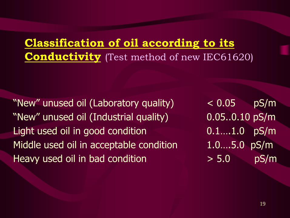
Classification of oil according to its
Conductivity (Test method of new IEC61620)
“New” unused oil (Laboratory quality) < 0.05 pS/m
“New” unused oil (Industrial quality) 0.05..0.10 pS/m
Light used oil in good condition 0.1….1.0 pS/m
Middle used oil in acceptable condition 1.0….5.0 pS/m
Heavy used oil in bad condition > 5.0 pS/m
20
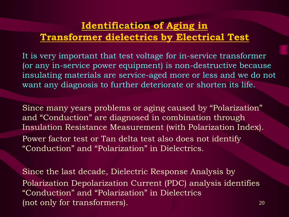
Identification of Aging in
Transformer dielectrics by Electrical Test
It is very important that test voltage for in-service transformer
(or any in-service power equipment) is non-destructive because
insulating materials are service-aged more or less and we do not
want any diagnosis to further deteriorate or shorten its life.
Since many years problems or aging caused by “Polarization”
and “Conduction” are diagnosed in combination through
Insulation Resistance Measurement (with Polarization Index).
Power factor test or Tan delta test also does not identify
“Conduction” and “Polarization” in Dielectrics.
Since the last decade, Dielectric Response Analysis by
Polarization Depolarization Current (PDC) analysis identifies
“Conduction” and “Polarization” in Dielectrics
(not only for transformers).
21
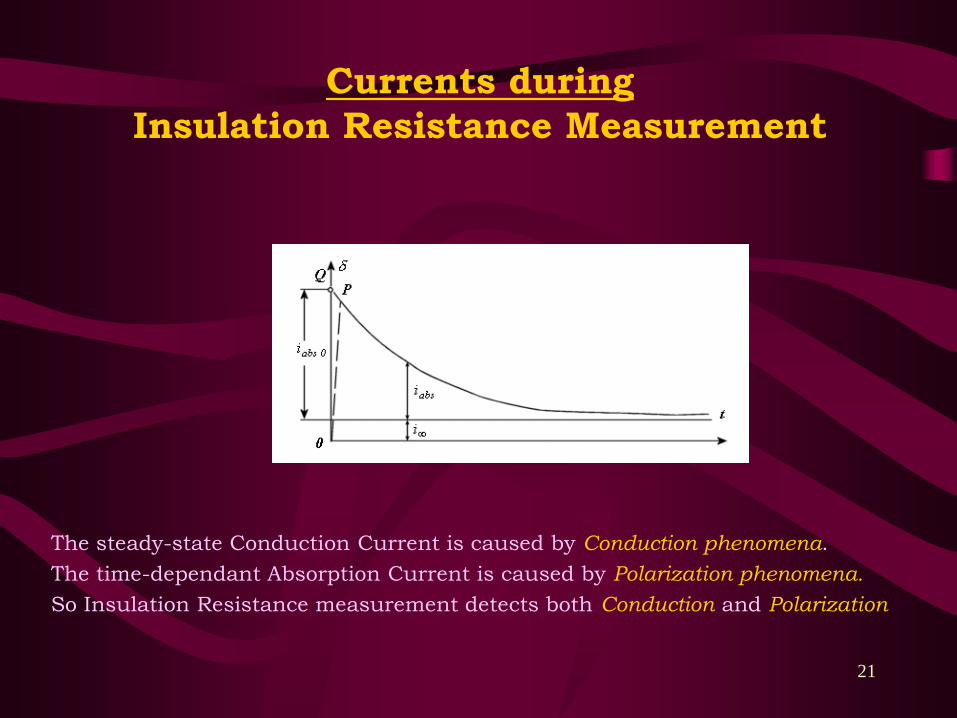
Currents during
Insulation Resistance Measurement
The steady-state Conduction Current is caused by Conduction phenomena.
The time-dependant Absorption Current is caused by Polarization phenomena.
So Insulation Resistance measurement detects both Conduction and Polarization

22
Principle of Test arrangement
for PDC measurement
Current measurement: from 1 pA
HV equipment can be tested at low voltage (e.g. 50V)

23
Insulation between windings
a New Power Transformer
Measurement results of Polarisation Depolarisation Currents
1.E-11
1.E-10
1.E-09
1.E-08
1.E-07
1 10 100 1,000 10,000
Time (s)
Cu
rren
t (A
)
Test Voltage 100V
Polarisation Current
Depolarisation Current
24
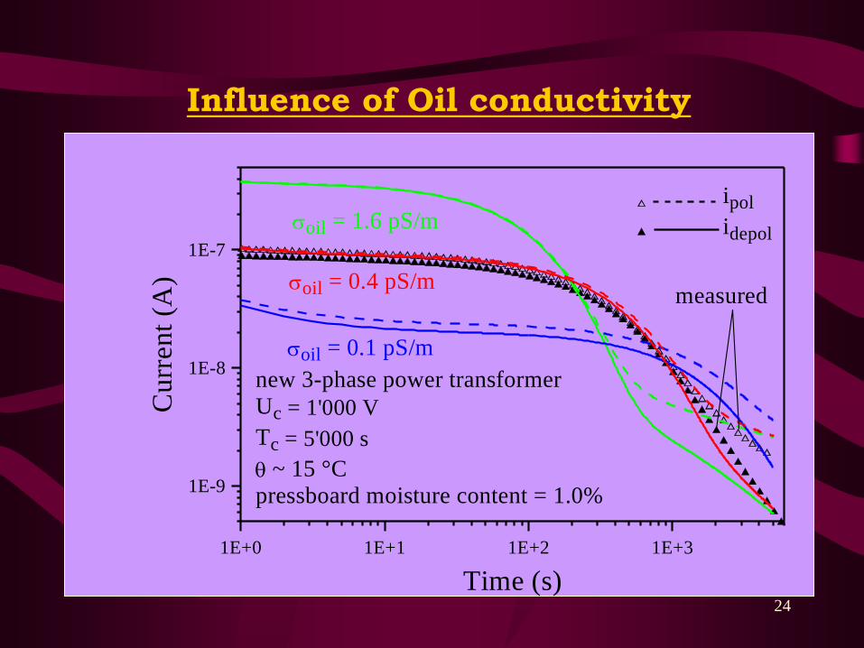
Influence of Oil conductivity
1E+0 1E+1 1E+2 1E+3
Time (s)
1E-9
1E-8
1E-7
Cu
rren
t (A
)ipol
idepol
new 3-phase power transformer
Uc = 1'000 V
Tc = 5'000 s
q ~ 15 °C
pressboard moisture content = 1.0%.
measured
soil = 0.1 pS/m
soil = 0.4 pS/m
soil = 1.6 pS/m
25
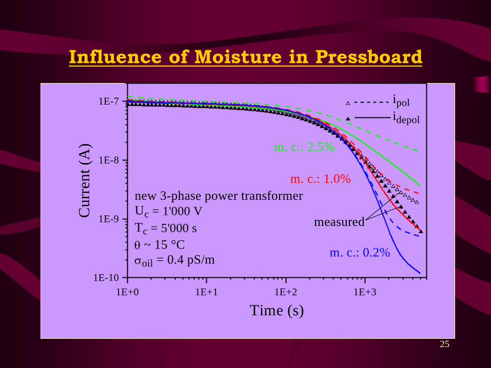
Influence of Moisture in Pressboard
1E+0 1E+1 1E+2 1E+3
Time (s)
1E-10
1E-9
1E-8
1E-7
Cu
rren
t (A
)ipol
idepol
new 3-phase power transformer
Uc = 1'000 V
Tc = 5'000 s
q ~ 15 °C
soil = 0.4 pS/m
.
measured
m. c.: 0.2%
m. c.: 1.0%
m. c.: 2.5%

26
Insulation between windings
Power Transformers
Measurement results of Polarisation Depolarisation Currents

27
Insulation between windings3f, 20 MVA, 33/11 kV Transformer
PDC Test on Transformer without oil
(Teat Voltage 100 V)
Measurement results of Polarisation Depolarisation Currents

28
Some PDC Measurement results
1.E-11
1.E-10
1.E-09
1.E-08
1 10 100 1,000 10 ,000
Time (s)
Cu
rren
t (A
)
T4
T5(5.7)
PDC at 50V, 20oC
(no oil)
1.E-11
1.E-10
1.E-09
1.E-08
1.E-07
1 10 100 1,000 10 ,000
Time (s)
Cu
rren
t (A
)
I pol.
I depol.
PDC at 50V, 30oC
(no oil)
(5.9)1.E-11
1.E-10
1.E-09
1.E-08
1.E-07
1 10 100 1,000 10 ,000
Time (s)
Cu
rren
t (A
)
I pol.
I depol.
PDC at 50V, 24oC
(no oil)
(5.8)
1.E-09
1.E-08
1.E-07
1 10 100 1,000 10 ,000
Time (s)
Cu
rren
t (A
)
(5.2)I pol.
I depol.
PDC at 500V, 5oC
1.E-11
1.E-10
1.E-09
1.E-08
1.E-07
1 10 100 1,000 10 ,000
Time (s)
Cu
rren
t (A
)
(5.1)I pol.
I depol.
PDC at 100V, 18oC
1.E-10
1.E-09
1.E-08
1 10 100 1,000 10 ,000
Time (s)
Cu
rren
t (A
)
I pol.
I depol.
PDC at 100V, 25oC
(5.3)
1.E-10
1.E-09
1.E-08
1.E-07
1.E-06
1 10 100 1,000 10 ,000
Time (s)
Cu
rren
t (A
)
I pol.
I depol.
(5.4)
PDC at 100V, 15oC
1.E-10
1.E-09
1.E-08
1.E-07
1.E-06
1 10 100 1,000 10 ,000
Time (s)
Cu
rren
t (A
)
I pol.
I depol.
(5.5)
PDC at 100V, 23oC
1.E-10
1.E-09
1.E-08
1.E-07
1.E-06
1 10 100 1,000 10 ,000
Time (s)
Cu
rren
t (A
)
I pol.
I depol.
PDC at 100V, 26oC
(5.6)
From: S. Bhumiwat, S. Lowe, P. Nething, J. Perera, P. Wickramasuriya, P. Kuansatit,
“Performance of oil and paper in transformers based on IEC61620 and dielectric
response techniques.” IEEE EI Magazine, vol. 26 no. 3, May/June 2010, pp. 16-23.
(can be downloaded from www.kea-consultant.com)

29
PDC Measurement Resultsof a Transformer which has
Overheating in the Solid Insulation between windings
From a case study in “Identification of overheating in transformer solid insulation
by Polarization Depolarization Current Analysis” by Supatra A. Bhumiwat,
in 2013 Electrical Insulation Conference, Ottawa, Canada, 2-5 June 2013
(can be downloaded from www.kea-consultant.com)
30
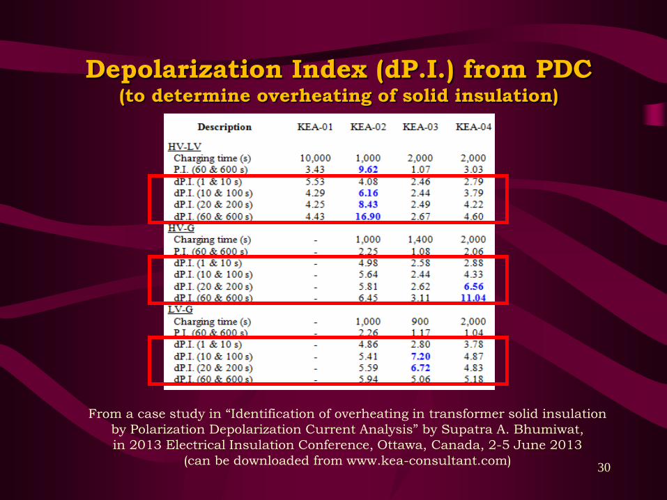
Depolarization Index (dP.I.) from PDC(to determine overheating of solid insulation)
From a case study in “Identification of overheating in transformer solid insulation
by Polarization Depolarization Current Analysis” by Supatra A. Bhumiwat,
in 2013 Electrical Insulation Conference, Ottawa, Canada, 2-5 June 2013
(can be downloaded from www.kea-consultant.com)

31
Evaluation of
PDC Measurement Results
• Oil Conductivity (only oil-paper transformer)
• Moisture in paper (any oil-paper equipment)
• Insulation Resistance and Polarisation Index
• Frequency scan of Capacitance
• Frequency scan of DDF (tan d)
• Recovery Voltage Polarisation Spectrum

32
Evaluation of
Insulation Resistance between windings and P.I.
Polarisation Current
1.E+10
1.E+11
1.E+12
1 10 100 1,000 10,000
Time (s)
Resi
sta
nce (
W)

33
Insulation between windings
Power Transformers
R 1 min. 72.1 GW
R 10 min. 99.8 GW
PI 1.38
tan d at 1 Hz 0.09%
Moisture in pressboard 1.0%
Oil conductivity at 20oC 0.32 pS/m
R 1 min. 63.5 GW
R 10 min. 78.6 GW
PI 1.24
tan d at 1 Hz 0.09%
Moisture in pressboard 1.5%
Oil conductivity at 20oC 0.12 pS/m
Polarisation Index is not a key to judge the wetness of Transformer insulation.

34
PDC Evaluation of
Capacitance and DDF

35
Capacitance and DDF
1E-4 1E-3 1E-2 1E-1 1E+0 1E+1 1E+2 1E+3 1E+4
Frequency (Hz)
1E-3
1E-2
1E-1
1E+0
tan
d
tand
.
unaged (m.c.: 4.0%)
unaged (m.c.: 2.5%)
2mm pressboard, q = 20 °C
unaged (m.c.: 1.0%)
unaged (m.c.: 0.2%)
1E-4 1E-3 1E-2 1E-1 1E+0 1E+1 1E+2 1E+3 1E+4
Frequency (Hz)
200
300
400
C' (p
F)
C'
.
unaged (m.c.: 4.0%)
unaged (m.c.: 2.5%)
2mm pressboard, q = 20 °C
unaged (m.c.: 1.0%)
unaged (m.c.: 0.2%)
C & tan delta is more sensitive at lower frequencies than at 50 Hz for the diagnosis
of aging in dielectrics. Tan delta tells you good / bad but does not tell you why.
Deterioration in insulating materials increase Capacitance at low frequencies.
Since previous decade (at the same time of PDC), there has been a diagnostic tool
which determines moisture in paper/pressboard based on frequency domain.
36
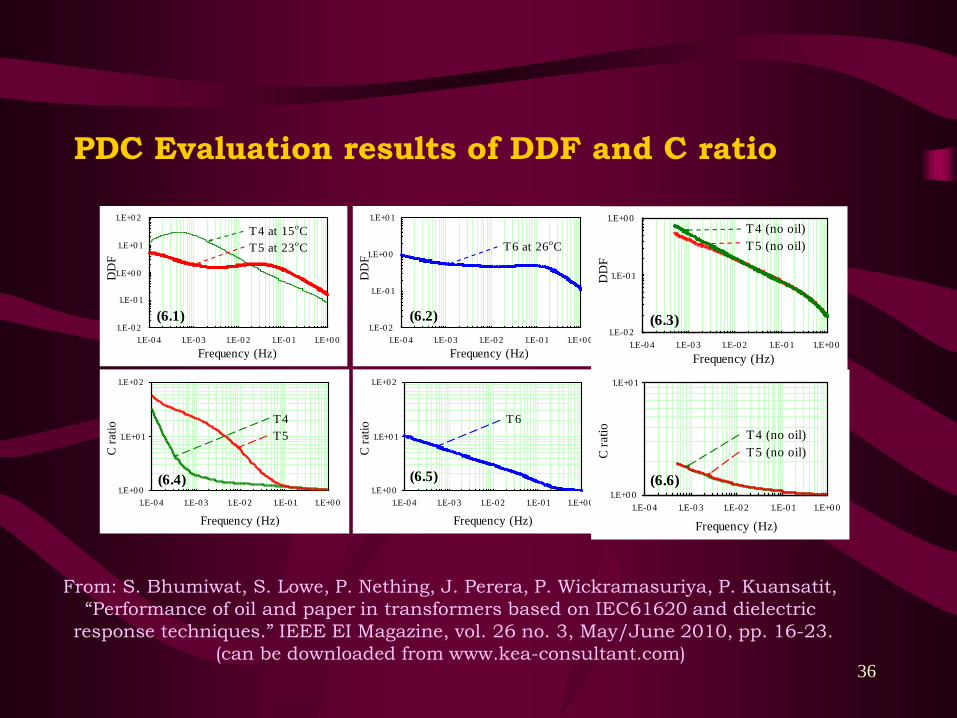
PDC Evaluation results of DDF and C ratio
1.E-02
1.E-01
1.E+00
1.E+01
1.E-04 1.E-03 1.E-02 1.E-01 1.E+00
Frequency (Hz)D
DF
T6 at 26oC
(6.2)1.E-02
1.E-01
1.E+00
1.E+01
1.E+02
1.E-04 1.E-03 1.E-02 1.E-01 1.E+00
Frequency (Hz)
DD
F
T4 at 15oC
T5 at 23oC
(6.1)
1.E+00
1.E+01
1.E+02
1.E-04 1.E-03 1.E-02 1.E-01 1.E+00
Frequency (Hz)
C r
atio
T6
(6.5)1.E+00
1.E+01
1.E+02
1.E-04 1.E-03 1.E-02 1.E-01 1.E+00
Frequency (Hz)
C r
atio
T4
T5
(6.4)1.E+00
1.E+01
1.E-04 1.E-03 1.E-02 1.E-01 1.E+00
Frequency (Hz)
C r
atio T4 (no oil)
T5 (no oil)
(6.6)
1.E-02
1.E-01
1.E+00
1.E-04 1.E-03 1.E-02 1.E-01 1.E+00
Frequency (Hz)
DD
F
(6.3)
T4 (no oil)
T5 (no oil)
From: S. Bhumiwat, S. Lowe, P. Nething, J. Perera, P. Wickramasuriya, P. Kuansatit,
“Performance of oil and paper in transformers based on IEC61620 and dielectric
response techniques.” IEEE EI Magazine, vol. 26 no. 3, May/June 2010, pp. 16-23.
(can be downloaded from www.kea-consultant.com)
37
Conclusion
1. Every problem in a dielectric is produced by
mechanism of “Conduction” or “Polarization” or
both. Aging behavior of transformer dielectric can
be classified by its nature.
2. It is important to choose diagnostic tool which
can identify problem or identify the aging type of
the dielectric, in order to solve the problem
correctly so insulation life can be prolonged.
3. The use of non-destructive technique or low
voltage methods ensures that the trouble or fault
is not modified or worsen by the tests.
38
THANK YOU
Publications can be downloaded from:
www.kea-consultant.com
More questions? Please contact