diagnostic manual (ems)
TRANSCRIPT

© 2010 Mahindra & Mahindra Ltd. All rights reserved. This book may not be reproduced or copied, in whole or in part, without the written permission of Mahindra & Mahindra Ltd.
DIAGNOSTIC MANUAL (EMS)
mDi CRDe
www.teknetmahindra.com
RELEASED BY - TECHNICAL PUBLICATION CELL MAHINDRA & MAHINDRA LTD. Rev1 – JANUARY 2010
All information contained in this manual is most up-to-date at the time of publication. However, specifications and procedures are subject to change without notice. This manual is strictly meant for restricted internal circulation within M&M Authorized dealer service centers.
MAN-00080
© 2010 Mahindra & Mahindra Ltd. All rights reserved. This book may not be reproduced or copied, in whole or in part, without the written permission of Mahindra & Mahindra Ltd.
ABOUT THE EMS DIAGNOSTIC MANUAL
The EMS(Engine Management System) diagnostic manual outlines the detailed procedures to troubleshoot complaints related to the Common Rail Diesel Engine and its controller (EMS ECU – EDC 17) fitted on XYLO mDi CRDe vehicle. Procedures to treat each DTC retrieved from the EMS ECU is given in a step by step , trouble-shooting tree structure.
This manual covers –
• EMS ECU re-programming/Re-flashing procedures, including micro-hybrid related parameters.
• Trouble shooting and diagnosis of DTCs (Defect Trouble Codes)
• Actuator tests
• Symptom Based diagnosis
The EMS ECU is linked to Engine immobilizer ECU(ICU) system and hence it is recommended that only trained CoTEKs carryout re-programming operations in the system, if required. XYLO mDi CRDe diagnostics are CAN based and hence certain procedures might differ from the earlier versions.
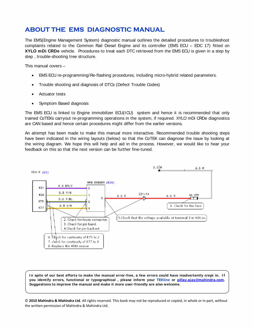
An attempt has been made to make this manual more interactive. Recommended trouble shooting steps have been indicated in the wiring layouts (below) so that the CoTEK can diagnose the issue by looking at the wiring diagram. We hope this will help and aid in the process. However, we would like to hear your feedback on this so that the next version can be further fine-tuned.
In spite of our best efforts to make the manual error-free, a few errors could have inadvertently crept in. If you identify errors, functional or typographical , please inform your TEKline or [email protected]. Suggestions to improve the manual and make it more user-friendly are also welcome.
Diagnostic Manual (EMS) MAN-00080-1 Xylo mDI CRDe January 2010/Rev 1
All copyrights reserved by The repair methods given by the manufacturer in this document are based on the technical specifications, current at the time of release. The methods may be modified as a result of changes introduced by the manufacturer in the production of the various component units and accessories from which the vehicles are manufactured. The reproduction, translation, transmission, in part of or whole of the present document, are prohibited without the prior written consent of Mahindra & Mahindra Ltd. The use of this document by any person other than the trained personnel, at the Authorized Service Centre of Mahindra & Mahindra Ltd., will amount to unauthorized use and shall be liable for penalty/prosecution© 2010 Mahindra & Mahindra Ltd.
Contents How to use this manual
Overview of the in‐vehicle communication network
Recommended Trouble shooting Process
Warranty & Other Information IQA/IMA code Programming
EMS ECU Re‐Programming/Flashing
List of DTC codes
Symptom Based Diagnosis
Conformity Check‐Resistance Values
Wiring Diagram
Diagnostic Manual (EMS) MAN-00080-2 Xylo mDI CRDe January 2010/Rev 1
All copyrights reserved by The repair methods given by the manufacturer in this document are based on the technical specifications, current at the time of release. The methods may be modified as a result of changes introduced by the manufacturer in the production of the various component units and accessories from which the vehicles are manufactured. The reproduction, translation, transmission, in part of or whole of the present document, are prohibited without the prior written consent of Mahindra & Mahindra Ltd. The use of this document by any person other than the trained personnel, at the Authorized Service Centre of Mahindra & Mahindra Ltd., will amount to unauthorized use and shall be liable for penalty/prosecution© 2010 Mahindra & Mahindra Ltd.
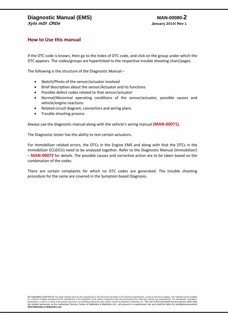
How to Use this manual If the DTC code is known, then go to the Index of DTC code, and click on the group under which the DTC appears. The codes/groups are hyperlinked to the respective trouble shooting chart/pages. The following is the structure of the Diagnostic Manual –
• Sketch/Photo of the sensor/actuator involved • Brief description about the sensor/Actuator and its functions • Possible defect codes related to that sensor/actuator • Normal/Abnormal operating conditions of the sensor/actuator, possible causes and
vehicle/engine reactions • Related circuit diagram, connectors and wiring plans • Trouble shooting process
Always use the diagnostic manual along with the vehicle’s wiring manual (MAN‐00071). The Diagnostic tester has the ability to test certain actuators. For Immobilizer related errors, the DTCs in the Engine EMS and along with that the DTCs in the Immobilizer ECU(ICU) need to be analyzed together. Refer to the Diagnostic Manual (Immobilizer) – MAN‐00072 for details. The possible causes and corrective action are to be taken based on the combination of the codes. There are certain complaints for which no DTC codes are generated. The trouble shooting procedure for the same are covered in the Symptom based Diagnosis.
Diagnostic Manual (EMS) MAN-00080-3 Xylo mDI CRDe January 2010/Rev 1
All copyrights reserved by The repair methods given by the manufacturer in this document are based on the technical specifications, current at the time of release. The methods may be modified as a result of changes introduced by the manufacturer in the production of the various component units and accessories from which the vehicles are manufactured. The reproduction, translation, transmission, in part of or whole of the present document, are prohibited without the prior written consent of Mahindra & Mahindra Ltd. The use of this document by any person other than the trained personnel, at the Authorized Service Centre of Mahindra & Mahindra Ltd., will amount to unauthorized use and shall be liable for penalty/prosecution© 2010 Mahindra & Mahindra Ltd.
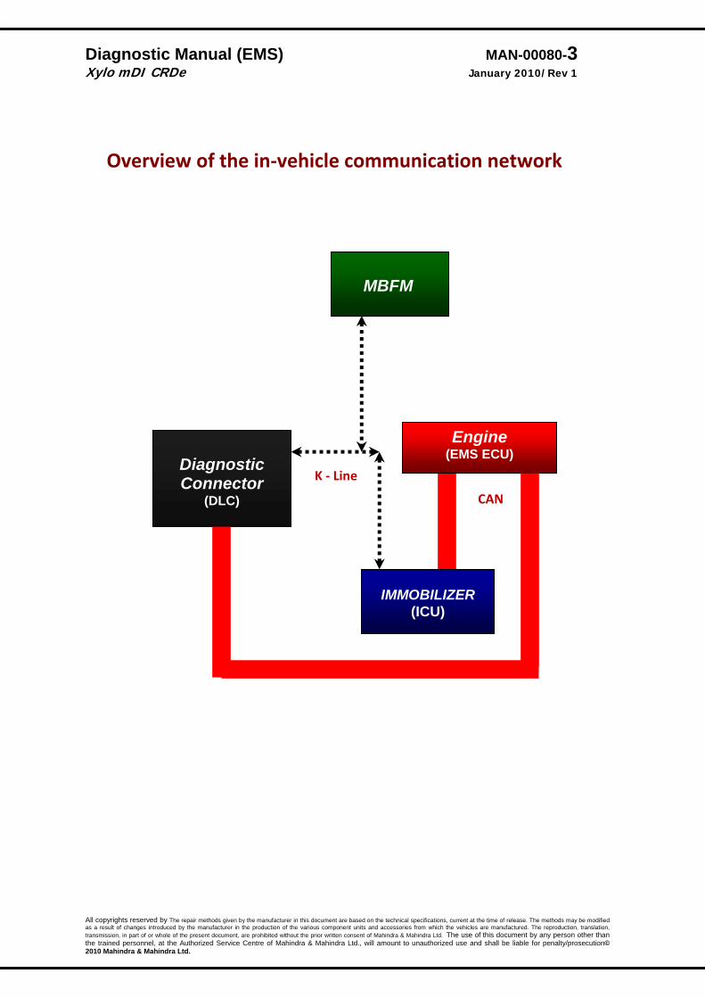
Overview of the in‐vehicle communication network
CAN
K ‐ Line
MBFM
Engine (EMS ECU)
Diagnostic Connector
(DLC)
IMMOBILIZER (ICU)
Diagnostic Manual (EMS) MAN-00080-4 Xylo mDI CRDe January 2010/Rev 1
All copyrights reserved by The repair methods given by the manufacturer in this document are based on the technical specifications, current at the time of release. The methods may be modified as a result of changes introduced by the manufacturer in the production of the various component units and accessories from which the vehicles are manufactured. The reproduction, translation, transmission, in part of or whole of the present document, are prohibited without the prior written consent of Mahindra & Mahindra Ltd. The use of this document by any person other than the trained personnel, at the Authorized Service Centre of Mahindra & Mahindra Ltd., will amount to unauthorized use and shall be liable for penalty/prosecution© 2010 Mahindra & Mahindra Ltd.
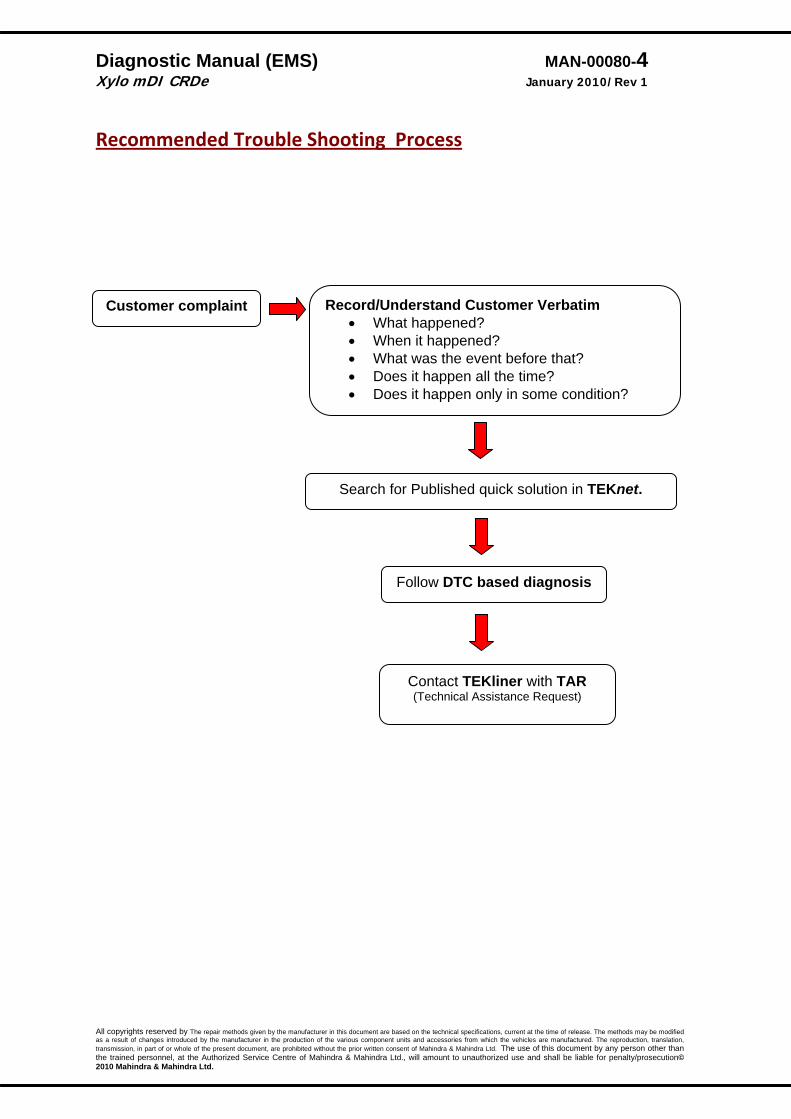
Recommended Trouble Shooting Process
Customer complaint Record/Understand Customer Verbatim • What happened? • When it happened? • What was the event before that? • Does it happen all the time? • Does it happen only in some condition?
Search for Published quick solution in TEKnet.
Follow DTC based diagnosis
Contact TEKliner with TAR (Technical Assistance Request)
Diagnostic Manual (EMS) MAN-00080-5 Xylo mDI CRDe January 2010/Rev 1
All copyrights reserved by The repair methods given by the manufacturer in this document are based on the technical specifications, current at the time of release. The methods may be modified as a result of changes introduced by the manufacturer in the production of the various component units and accessories from which the vehicles are manufactured. The reproduction, translation, transmission, in part of or whole of the present document, are prohibited without the prior written consent of Mahindra & Mahindra Ltd. The use of this document by any person other than the trained personnel, at the Authorized Service Centre of Mahindra & Mahindra Ltd., will amount to unauthorized use and shall be liable for penalty/prosecution© 2010 Mahindra & Mahindra Ltd.
Warranty & Other Information All failures/complaints encountered on EMS ECU and/or ICU controllers should be repo rted through a Common Rail Failure Report (CrFR)/Service Complaint Report (SCR). Replacement of any of the EMS ECU or ICU controller requires approval of the TEKline. Ensure that a TAR is raised# in the TEKnet website for approval, attaching the CrFR/SCR. While raising a warranty claim, the TAR no should be quoted on the warranty claim. # Only a trained and certified CoTEK can raise a TAR (in TEKnet website)
IQA/IMA Code Programming An ECU controlled engine needs precise metering of fuel. Due to manufacturing tolerances, each injector deviates slightly from its idealized behavior. Thus, each injector has a correction factor, which is engraved on top of it, in the form of a 6‐character alphanumeric code. This is known as an IQA code/IMA code. For optimal performance of the engine, the ECU needs to know the IQA code/IMA code of each injector. This information is programmed into the ECU when the vehicle is manufactured. However, if you need to replace an injector(s), then the IQA code/IMA code for that new injector has to be updated in the ECU. The cylinder number is with respect fan. As a first step, you need to select the cylinder number of the injector being replaced. After the cylinder number is selected by clicking on the check‐button next to the number, the IQA code/IMA code should be entered in the box provided. Click the button to the right of the text box. If the Injector code is valid and accepted by the ECU, a message is displayed, indicating that the operation is performed successfully. A message “Invalid IQA code” will be displayed , if an incorrect IQA/IMA code is keyed in. IQA codes are case sensitive. Programming IQA codes is an extremely important activity. In order to ensure that the correct code is entered and that it has been entered in the correct cylinder, SMART tester allows you to verify the codes that you have entered. Select an injector, and click the button below the ”Verify” line in figure. The IQA codes present in the ECU will be read back and displayed in the text box before this button. It is recommended that you carry out the verification activity whenever you change an IQA code. PLEASE ENSURE TO PROGRAM IQA/IMA CODES WHEN YOU REPLACE AN INJECTOR, ECU or ENGINE.
Diagnostic Manual (EMS) MAN-00080-6 Xylo mDI CRDe January 2010/Rev 1
All copyrights reserved by The repair methods given by the manufacturer in this document are based on the technical specifications, current at the time of release. The methods may be modified as a result of changes introduced by the manufacturer in the production of the various component units and accessories from which the vehicles are manufactured. The reproduction, translation, transmission, in part of or whole of the present document, are prohibited without the prior written consent of Mahindra & Mahindra Ltd. The use of this document by any person other than the trained personnel, at the Authorized Service Centre of Mahindra & Mahindra Ltd., will amount to unauthorized use and shall be liable for penalty/prosecution© 2010 Mahindra & Mahindra Ltd.
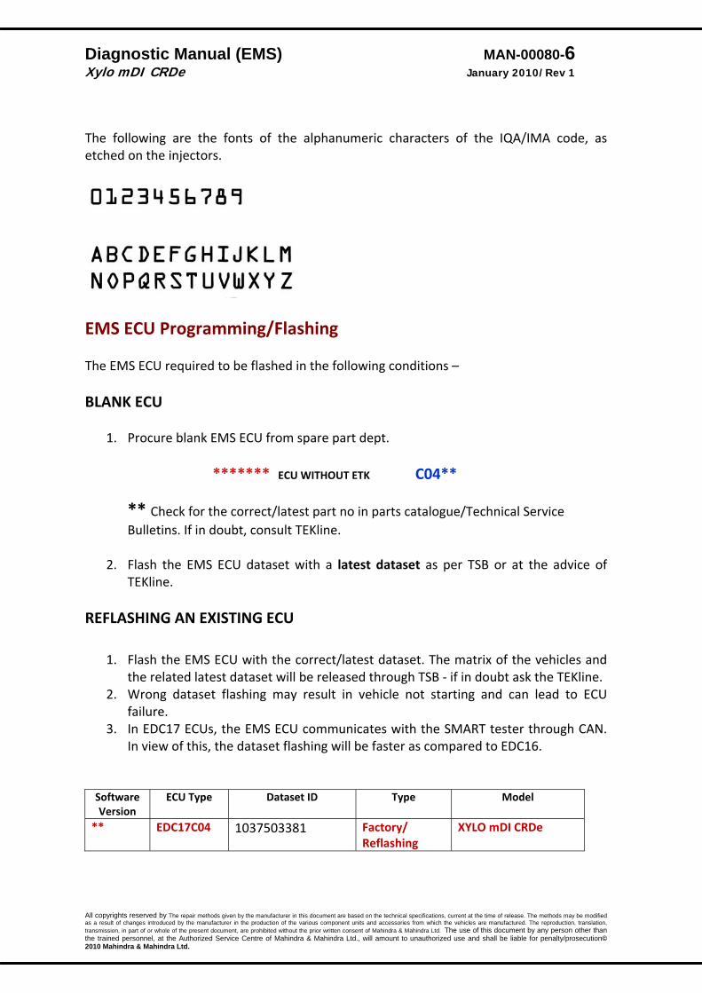
The following are the fonts of the alphanumeric characters of the IQA/IMA code, as etched on the injectors.
EMS ECU Programming/Flashing The EMS ECU required to be flashed in the following conditions – BLANK ECU
1. Procure blank EMS ECU from spare part dept.
******* ECU WITHOUT ETK C04**
** Check for the correct/latest part no in parts catalogue/Technical Service Bulletins. If in doubt, consult TEKline.
2. Flash the EMS ECU dataset with a latest dataset as per TSB or at the advice of
TEKline. REFLASHING AN EXISTING ECU
1. Flash the EMS ECU with the correct/latest dataset. The matrix of the vehicles and the related latest dataset will be released through TSB ‐ if in doubt ask the TEKline.
2. Wrong dataset flashing may result in vehicle not starting and can lead to ECU failure.
3. In EDC17 ECUs, the EMS ECU communicates with the SMART tester through CAN. In view of this, the dataset flashing will be faster as compared to EDC16.
Software Version
ECU Type Dataset ID Type Model
** EDC17C04 1037503381 Factory/ Reflashing
XYLO mDI CRDe
Diagnostic Manual (EMS) MAN-00080-7 Xylo mDI CRDe January 2010/Rev 1
All copyrights reserved by The repair methods given by the manufacturer in this document are based on the technical specifications, current at the time of release. The methods may be modified as a result of changes introduced by the manufacturer in the production of the various component units and accessories from which the vehicles are manufactured. The reproduction, translation, transmission, in part of or whole of the present document, are prohibited without the prior written consent of Mahindra & Mahindra Ltd. The use of this document by any person other than the trained personnel, at the Authorized Service Centre of Mahindra & Mahindra Ltd., will amount to unauthorized use and shall be liable for penalty/prosecution© 2010 Mahindra & Mahindra Ltd.
Notes –
1. Ensure that the there is no communication breakdown once the flashing begins. Check Python connections are secure.
2. Ensure that the SMART tester has ‐ • Enough battery reserve/Connected to AC power • Screen saver/Battery saver mode turned off, • Vehicle’s ignition is ON • Battery terminals connected securely. • Battery earth connection is good.
3. Never touch the ECU pins by hand/finger.
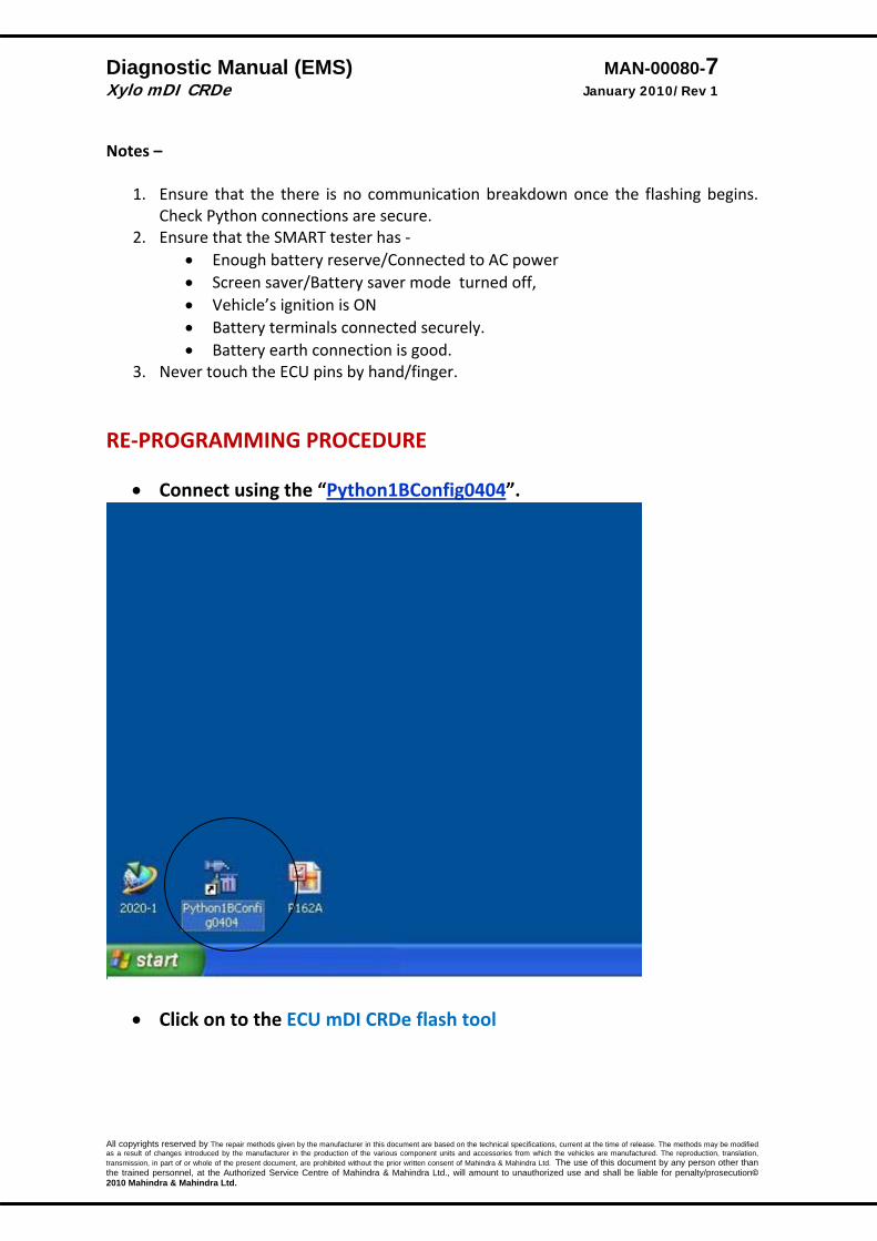
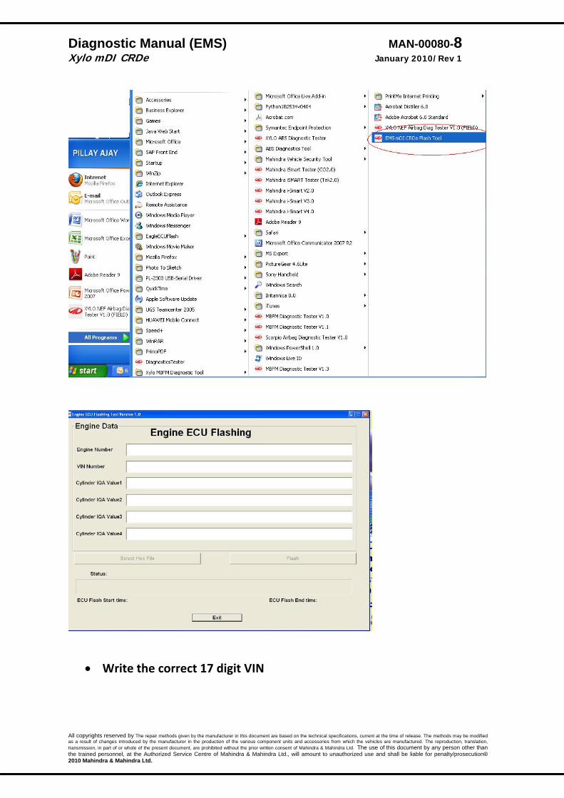
RE‐PROGRAMMING PROCEDURE
• Connect using the “Python1BConfig0404”.
• Click on to the ECU mDI CRDe flash tool
Diagnostic Manual (EMS) MAN-00080-8 Xylo mDI CRDe January 2010/Rev 1
All copyrights reserved by The repair methods given by the manufacturer in this document are based on the technical specifications, current at the time of release. The methods may be modified as a result of changes introduced by the manufacturer in the production of the various component units and accessories from which the vehicles are manufactured. The reproduction, translation, transmission, in part of or whole of the present document, are prohibited without the prior written consent of Mahindra & Mahindra Ltd. The use of this document by any person other than the trained personnel, at the Authorized Service Centre of Mahindra & Mahindra Ltd., will amount to unauthorized use and shall be liable for penalty/prosecution© 2010 Mahindra & Mahindra Ltd.
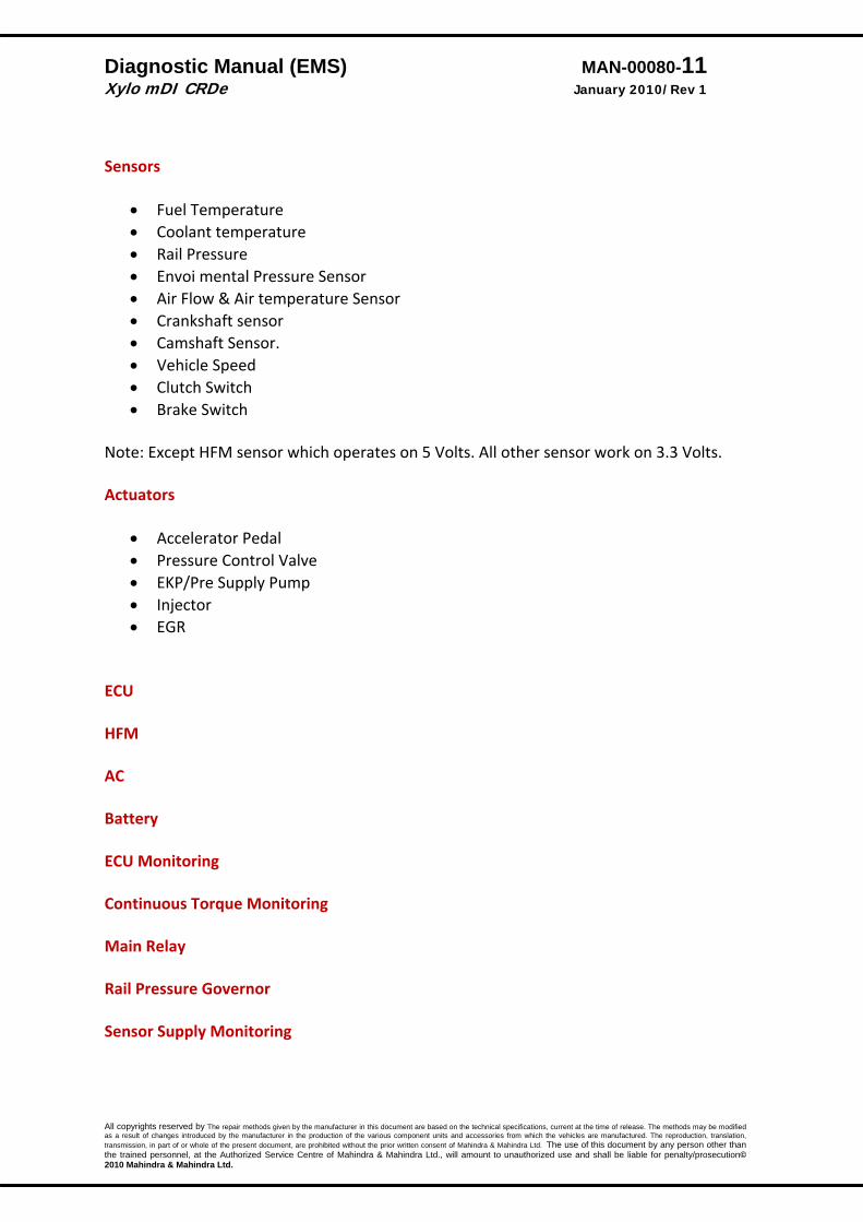
• Write the correct 17 digit VIN

Diagnostic Manual (EMS) MAN-00080-9 Xylo mDI CRDe January 2010/Rev 1
All copyrights reserved by The repair methods given by the manufacturer in this document are based on the technical specifications, current at the time of release. The methods may be modified as a result of changes introduced by the manufacturer in the production of the various component units and accessories from which the vehicles are manufactured. The reproduction, translation, transmission, in part of or whole of the present document, are prohibited without the prior written consent of Mahindra & Mahindra Ltd. The use of this document by any person other than the trained personnel, at the Authorized Service Centre of Mahindra & Mahindra Ltd., will amount to unauthorized use and shall be liable for penalty/prosecution© 2010 Mahindra & Mahindra Ltd.
• Click on “Browse • Select the applicable dataset and click “open”

Diagnostic Manual (EMS) MAN-00080-10 Xylo mDI CRDe January 2010/Rev 1
All copyrights reserved by The repair methods given by the manufacturer in this document are based on the technical specifications, current at the time of release. The methods may be modified as a result of changes introduced by the manufacturer in the production of the various component units and accessories from which the vehicles are manufactured. The reproduction, translation, transmission, in part of or whole of the present document, are prohibited without the prior written consent of Mahindra & Mahindra Ltd. The use of this document by any person other than the trained personnel, at the Authorized Service Centre of Mahindra & Mahindra Ltd., will amount to unauthorized use and shall be liable for penalty/prosecution© 2010 Mahindra & Mahindra Ltd.
• Click “Flash”
• After completion of flashing , switch OFF the ignition for 1 minute and switch it ON
• Learn the EMS with Immobilizer ECU (ICU) – Refer to diagnostic manual (immobilizer).
Diagnostic Manual (EMS) MAN-00080-11 Xylo mDI CRDe January 2010/Rev 1
All copyrights reserved by The repair methods given by the manufacturer in this document are based on the technical specifications, current at the time of release. The methods may be modified as a result of changes introduced by the manufacturer in the production of the various component units and accessories from which the vehicles are manufactured. The reproduction, translation, transmission, in part of or whole of the present document, are prohibited without the prior written consent of Mahindra & Mahindra Ltd. The use of this document by any person other than the trained personnel, at the Authorized Service Centre of Mahindra & Mahindra Ltd., will amount to unauthorized use and shall be liable for penalty/prosecution© 2010 Mahindra & Mahindra Ltd.
Sensors
• Fuel Temperature • Coolant temperature • Rail Pressure • Envoi mental Pressure Sensor • Air Flow & Air temperature Sensor • Crankshaft sensor • Camshaft Sensor. • Vehicle Speed • Clutch Switch • Brake Switch
Note: Except HFM sensor which operates on 5 Volts. All other sensor work on 3.3 Volts. Actuators
• Accelerator Pedal • Pressure Control Valve • EKP/Pre Supply Pump • Injector • EGR
ECU HFM AC Battery ECU Monitoring Continuous Torque Monitoring Main Relay Rail Pressure Governor Sensor Supply Monitoring
Diagnostic Manual (EMS) MAN-00080-12 Xylo mDI CRDe January 2010/Rev 1
All copyrights reserved by The repair methods given by the manufacturer in this document are based on the technical specifications, current at the time of release. The methods may be modified as a result of changes introduced by the manufacturer in the production of the various component units and accessories from which the vehicles are manufactured. The reproduction, translation, transmission, in part of or whole of the present document, are prohibited without the prior written consent of Mahindra & Mahindra Ltd. The use of this document by any person other than the trained personnel, at the Authorized Service Centre of Mahindra & Mahindra Ltd., will amount to unauthorized use and shall be liable for penalty/prosecution© 2010 Mahindra & Mahindra Ltd.
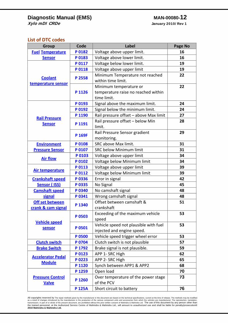
List of DTC codes Group Code Label Page No
Fuel Temperature Sensor
P 0182 Voltage above upper limit. 16 P 0183 Voltage above lower limit. 16
Coolant temperature sensor
P 0117 Voltage below lower limit. 19 P 0118 Voltage above upper limit 19
P 2558 Minimum Temperature not reached within time limit.
22
P 1126 Minimum temperature or temperature raise no reached within time limit.
22
Rail Pressure Sensor
P 0193 Signal above the maximum limit. 24 P 0192 Signal below the minimum limit. 24 P 1190 Rail pressure offset – above Max limit 27
P 1191 Rail pressure offset – below Min limit.
28
P 169F Rail Pressure Sensor gradient monitoring.
29
Environment Pressure Sensor
P 0108 SRC above Max limit. 31 P 0107 SRC below Minimum limit 31
Air flow P 0103 Voltage above upper limit 34 P 0102 Voltage below Minimum limit 34
Air temperature P 0113 Voltage above upper limit 39 P 0112 Voltage below Minimum limit 39
Crankshaft speed Sensor ( ISS)
P 0336 Error in signal 42 P 0335 No Signal 45
Camshaft speed signal
P 0340 No camshaft signal 48 P 0341 Wrong camshaft signal 48
Off set between crank & cam signal P 1340
Offset between camshaft & crankshaft
51
Vehicle speed sensor
P 0503 Exceeding of the maximum vehicle speed
53
P 0501 Vehicle speed not plausible with fuel injected and engine speed.
53
P 0500 Vehicle speed trigger wheel error 53 Clutch switch P 0704 Clutch switch is not plausible 57 Brake Switch P 1792 Brake signal is not plausible. 59
Accelerator Pedal Module
P 0123 APP 1‐ SRC High 62 P 0223 APP 2‐ SRC High 65 P 1120 Synch between APP1 & APP2 68
Pressure Control Valve
P 1259 Open load 70
P 1260 Over temperature of the power stage of the PCV
73
P 125A Short circuit to battery 76

Diagnostic Manual (EMS) MAN-00080-13 Xylo mDI CRDe January 2010/Rev 1
All copyrights reserved by The repair methods given by the manufacturer in this document are based on the technical specifications, current at the time of release. The methods may be modified as a result of changes introduced by the manufacturer in the production of the various component units and accessories from which the vehicles are manufactured. The reproduction, translation, transmission, in part of or whole of the present document, are prohibited without the prior written consent of Mahindra & Mahindra Ltd. The use of this document by any person other than the trained personnel, at the Authorized Service Centre of Mahindra & Mahindra Ltd., will amount to unauthorized use and shall be liable for penalty/prosecution© 2010 Mahindra & Mahindra Ltd.
P 125B Short circuit to Ground 79
Pre supply Pump (EPK)
P 163F Open load 82
P 1640 Over temperature of the ECU power stage for the Pre Supply Pump
85
P 163 E Short circuit to Ground 88 P 163D Short circuit to Battery 91
Injectors
P 0202 Injector bank failure. 94
P 1210 Chip error in the CY33x power stage component
97
P126C Injector valve, 1st Cylinder, Open Load
98
P127C Injector valve, 2nd Cylinder, Open Load
98
P128C Injector valve, 3rd Cylinder, Open Load
98
P129C Injector valve, 4th Cylinder, Open Load
98
P0261 Short circuit for injector 1 101P0264 Short circuit for injector 2 101 P0267 Short circuit for injector 3 101 P0270 Short circuit for injector 4 101
P0262 Short circuit high side to low side.‐injector 1
104
P0265 Short circuit high side to low side.‐injector 2
104
P0268 Short circuit high side to low side.‐injector 3
104
P0271 Short circuit high side to low side.‐ injector 4.
104
EGR
P0403 Open load 107
P0404 Over temperature in the power stage of the ECU
110
P0406 Short circuit to battery 113 P0405 Short circuit to ground. 116
ADC monitoring P 1700 Calibration time out error 119 P 1701 ADC conversion time out error 119
AC power stage P 1532 No load 120 P1533 Over temperature. 123 P1530 Short circuit to battery. 126 P1531 Short circuit to ground. 126
Battery P0563 SRC Max 129 P0562 SRC Min 129
Communication monitoring P 162A
Communication error of CJ940 130
Diagnostic Manual (EMS) MAN-00080-14 Xylo mDI CRDe January 2010/Rev 1
All copyrights reserved by The repair methods given by the manufacturer in this document are based on the technical specifications, current at the time of release. The methods may be modified as a result of changes introduced by the manufacturer in the production of the various component units and accessories from which the vehicles are manufactured. The reproduction, translation, transmission, in part of or whole of the present document, are prohibited without the prior written consent of Mahindra & Mahindra Ltd. The use of this document by any person other than the trained personnel, at the Authorized Service Centre of Mahindra & Mahindra Ltd., will amount to unauthorized use and shall be liable for penalty/prosecution© 2010 Mahindra & Mahindra Ltd.
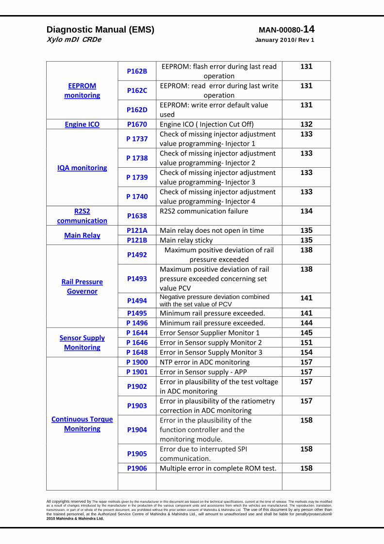
EEPROM monitoring
P162B EEPROM: flash error during last read
operation 131
P162C EEPROM: read error during last write
operation 131
P162D EEPROM: write error default value used
131
Engine ICO P1670 Engine ICO ( Injection Cut Off) 132
IQA monitoring
P 1737 Check of missing injector adjustment value programming‐ Injector 1
133
P 1738 Check of missing injector adjustment value programming‐ Injector 2
133
P 1739 Check of missing injector adjustment value programming‐ Injector 3
133
P 1740 Check of missing injector adjustment value programming‐ Injector 4
133
R2S2 communication P1638
R2S2 communication failure 134
Main Relay P121A Main relay does not open in time 135P121B Main relay sticky 135
Rail Pressure Governor
P1492 Maximum positive deviation of rail
pressure exceeded 138
P1493 Maximum positive deviation of rail pressure exceeded concerning set value PCV
138
P1494 Negative pressure deviation combined with the set value of PCV
141
P1495 Minimum rail pressure exceeded. 141P 1496 Minimum rail pressure exceeded. 144
Sensor Supply Monitoring
P 1644 Error Sensor Supplier Monitor 1 145 P 1646 Error in Sensor supply Monitor 2 151P 1648 Error in Sensor Supply Monitor 3 154
Continuous Torque Monitoring
P 1900 NTP error in ADC monitoring 157P 1901 Error in Sensor supply ‐ APP 157
P1902 Error in plausibility of the test voltage in ADC monitoring
157
P1903 Error in plausibility of the ratiometry correction in ADC monitoring
157
P1904 Error in the plausibility of the function controller and the monitoring module.
158
P1905 Error due to interrupted SPI communication.
158
P1906 Multiple error in complete ROM test. 158
Diagnostic Manual (EMS) MAN-00080-15 Xylo mDI CRDe January 2010/Rev 1
All copyrights reserved by The repair methods given by the manufacturer in this document are based on the technical specifications, current at the time of release. The methods may be modified as a result of changes introduced by the manufacturer in the production of the various component units and accessories from which the vehicles are manufactured. The reproduction, translation, transmission, in part of or whole of the present document, are prohibited without the prior written consent of Mahindra & Mahindra Ltd. The use of this document by any person other than the trained personnel, at the Authorized Service Centre of Mahindra & Mahindra Ltd., will amount to unauthorized use and shall be liable for penalty/prosecution© 2010 Mahindra & Mahindra Ltd.
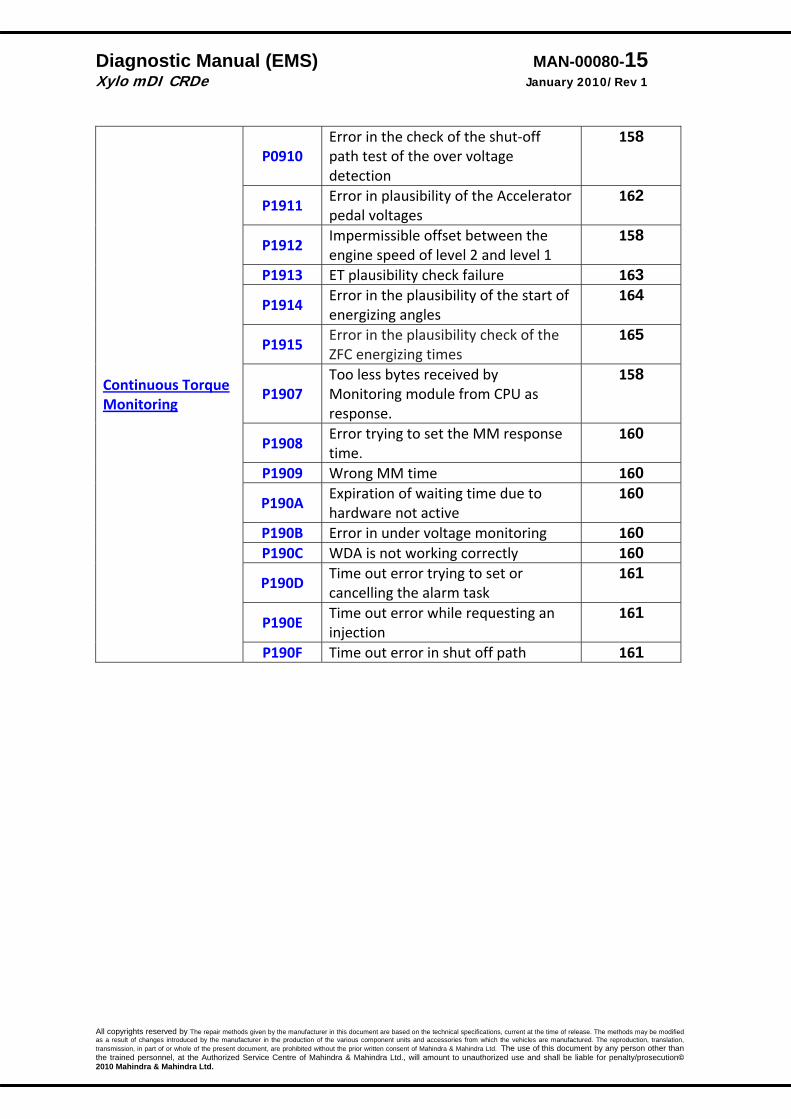
Continuous Torque Monitoring
P0910 Error in the check of the shut‐off path test of the over voltage detection
158
P1911 Error in plausibility of the Accelerator pedal voltages
162
P1912 Impermissible offset between the engine speed of level 2 and level 1
158
P1913 ET plausibility check failure 163
P1914 Error in the plausibility of the start of energizing angles
164
P1915 Error in the plausibility check of the ZFC energizing times
165
P1907 Too less bytes received by Monitoring module from CPU as response.
158
P1908 Error trying to set the MM response time.
160
P1909 Wrong MM time 160
P190A Expiration of waiting time due to hardware not active
160
P190B Error in under voltage monitoring 160P190C WDA is not working correctly 160
P190D Time out error trying to set or cancelling the alarm task
161
P190E Time out error while requesting an injection
161
P190F Time out error in shut off path 161
Diagnostic Manual (EMS) MAN-00080-16 Xylo mDI CRDe January 2010/Rev 1
All copyrights reserved by The repair methods given by the manufacturer in this document are based on the technical specifications, current at the time of release. The methods may be modified as a result of changes introduced by the manufacturer in the production of the various component units and accessories from which the vehicles are manufactured. The reproduction, translation, transmission, in part of or whole of the present document, are prohibited without the prior written consent of Mahindra & Mahindra Ltd. The use of this document by any person other than the trained personnel, at the Authorized Service Centre of Mahindra & Mahindra Ltd., will amount to unauthorized use and shall be liable for penalty/prosecution© 2010 Mahindra & Mahindra Ltd.
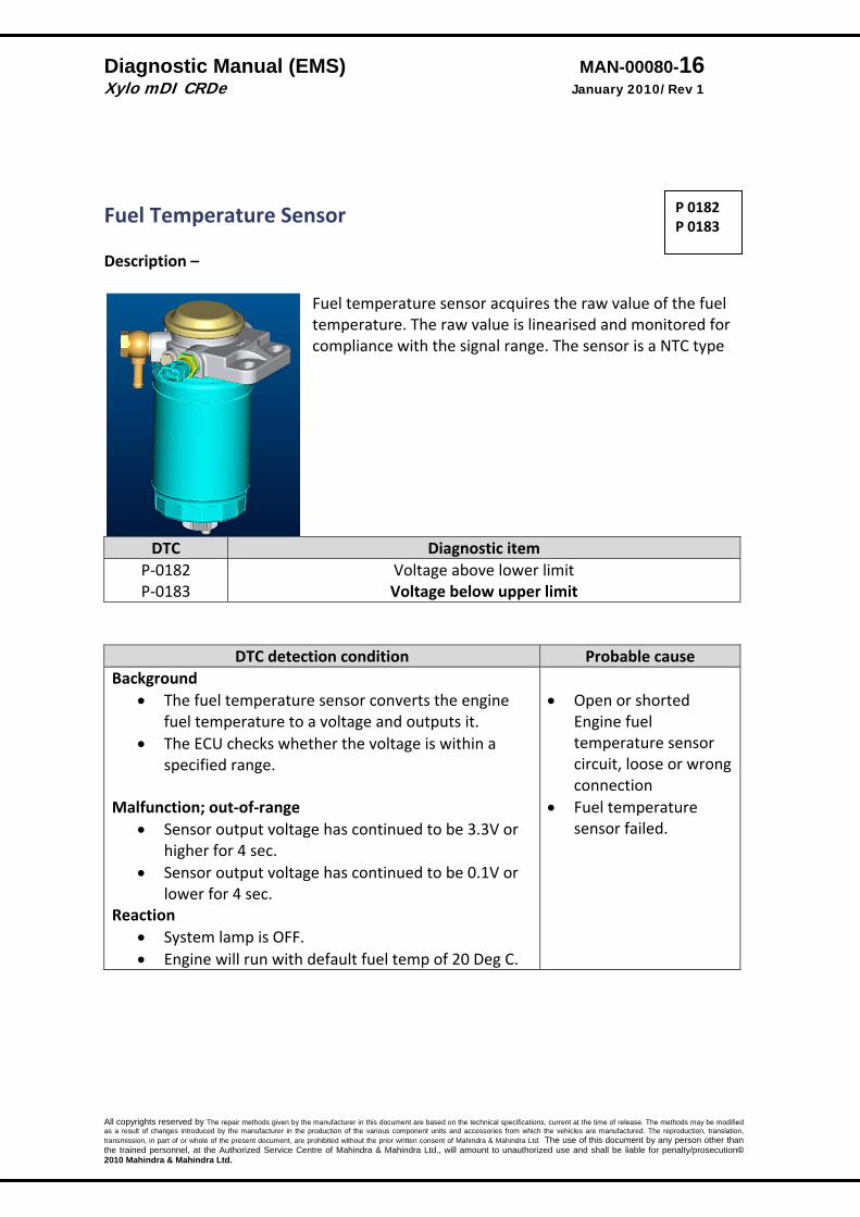
Fuel Temperature Sensor Description –
Fuel temperature sensor acquires the raw value of the fuel temperature. The raw value is linearised and monitored for compliance with the signal range. The sensor is a NTC type
DTC Diagnostic item P‐0182 P‐0183
Voltage above lower limit Voltage below upper limit
DTC detection condition Probable cause Background
• The fuel temperature sensor converts the engine fuel temperature to a voltage and outputs it.
• The ECU checks whether the voltage is within a specified range.
Malfunction; out‐of‐range
• Sensor output voltage has continued to be 3.3V or higher for 4 sec.
• Sensor output voltage has continued to be 0.1V or lower for 4 sec.
Reaction • System lamp is OFF. • Engine will run with default fuel temp of 20 Deg C.
• Open or shorted
Engine fuel temperature sensor circuit, loose or wrong connection
• Fuel temperature sensor failed.
P 0182 P 0183

Diagnostic Manual (EMS) MAN-00080-17 Xylo mDI CRDe January 2010/Rev 1
All copyrights reserved by The repair methods given by the manufacturer in this document are based on the technical specifications, current at the time of release. The methods may be modified as a result of changes introduced by the manufacturer in the production of the various component units and accessories from which the vehicles are manufactured. The reproduction, translation, transmission, in part of or whole of the present document, are prohibited without the prior written consent of Mahindra & Mahindra Ltd. The use of this document by any person other than the trained personnel, at the Authorized Service Centre of Mahindra & Mahindra Ltd., will amount to unauthorized use and shall be liable for penalty/prosecution© 2010 Mahindra & Mahindra Ltd.
P 0182 P 0183
Diagnostic Manual (EMS) MAN-00080-18 Xylo mDI CRDe January 2010/Rev 1
All copyrights reserved by The repair methods given by the manufacturer in this document are based on the technical specifications, current at the time of release. The methods may be modified as a result of changes introduced by the manufacturer in the production of the various component units and accessories from which the vehicles are manufactured. The reproduction, translation, transmission, in part of or whole of the present document, are prohibited without the prior written consent of Mahindra & Mahindra Ltd. The use of this document by any person other than the trained personnel, at the Authorized Service Centre of Mahindra & Mahindra Ltd., will amount to unauthorized use and shall be liable for penalty/prosecution© 2010 Mahindra & Mahindra Ltd.
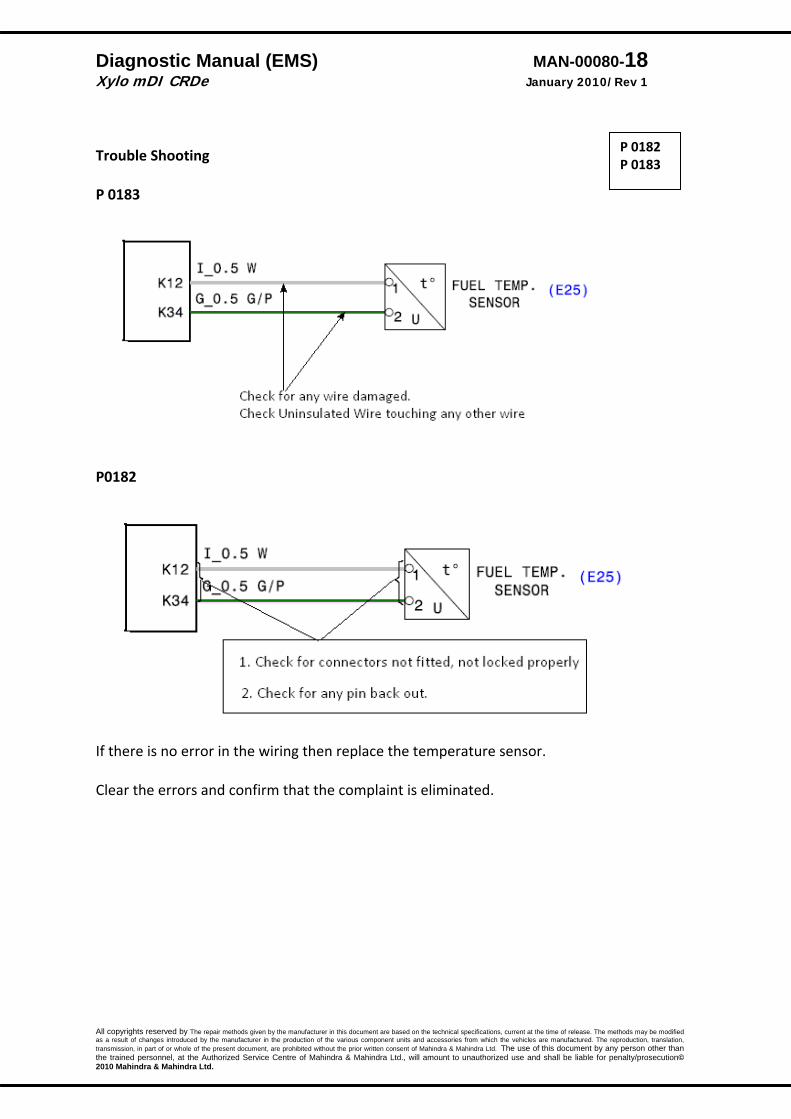
Trouble Shooting P 0183
P0182
If there is no error in the wiring then replace the temperature sensor. Clear the errors and confirm that the complaint is eliminated.
P 0182 P 0183

Diagnostic Manual (EMS) MAN-00080-19 Xylo mDI CRDe January 2010/Rev 1
All copyrights reserved by The repair methods given by the manufacturer in this document are based on the technical specifications, current at the time of release. The methods may be modified as a result of changes introduced by the manufacturer in the production of the various component units and accessories from which the vehicles are manufactured. The reproduction, translation, transmission, in part of or whole of the present document, are prohibited without the prior written consent of Mahindra & Mahindra Ltd. The use of this document by any person other than the trained personnel, at the Authorized Service Centre of Mahindra & Mahindra Ltd., will amount to unauthorized use and shall be liable for penalty/prosecution© 2010 Mahindra & Mahindra Ltd.
Coolant Temperature Sensor
Description: The Coolant temperature sensor (CTS) is located in the cylinder head near the thermostat. The CTS sensor is a variable resistor whose resistance changes as the temperature of the engine coolant flowing past the sensor changes.(NTC resistor) When the coolant temperature is low, the sensor resistance is high; when the coolant temperature is high, the sensor resistance is low. The ECU checks CTS voltage and uses the information to help smoothen the engine operation.
DTC Diagnostic item P‐0118 P‐0117
Voltage above upper limit Voltage below lower limit
DTC detection condition Probable cause
Background • The engine coolant temperature sensor converts
the engine coolant temperature to a voltage and outputs it.
• The ECU checks whether the voltage is within a specified range. In addition, it checks that the engine coolant temperature (signal) does not drop while the engine is warming up.
Malfunction; out‐of‐range
• Sensor output voltage has continued to be 3.3V or higher for 4 sec.
• Sensor output voltage has continued to be 0.1V or lower for 4 sec.
Reaction:
• System lamp will be on. • Power will be reduced • EGR will not work. • Temperature indication will not work.
• Open or shorted
Engine Coolant Temperature sensor circuit, or loose or wrong connection
• Engine Coolant Temperature sensor failed.
P‐0118 P‐0117

Diagnostic Manual (EMS) MAN-00080-20 Xylo mDI CRDe January 2010/Rev 1
All copyrights reserved by The repair methods given by the manufacturer in this document are based on the technical specifications, current at the time of release. The methods may be modified as a result of changes introduced by the manufacturer in the production of the various component units and accessories from which the vehicles are manufactured. The reproduction, translation, transmission, in part of or whole of the present document, are prohibited without the prior written consent of Mahindra & Mahindra Ltd. The use of this document by any person other than the trained personnel, at the Authorized Service Centre of Mahindra & Mahindra Ltd., will amount to unauthorized use and shall be liable for penalty/prosecution© 2010 Mahindra & Mahindra Ltd.

Diagnostic Manual (EMS) MAN-00080-21 Xylo mDI CRDe January 2010/Rev 1
All copyrights reserved by The repair methods given by the manufacturer in this document are based on the technical specifications, current at the time of release. The methods may be modified as a result of changes introduced by the manufacturer in the production of the various component units and accessories from which the vehicles are manufactured. The reproduction, translation, transmission, in part of or whole of the present document, are prohibited without the prior written consent of Mahindra & Mahindra Ltd. The use of this document by any person other than the trained personnel, at the Authorized Service Centre of Mahindra & Mahindra Ltd., will amount to unauthorized use and shall be liable for penalty/prosecution© 2010 Mahindra & Mahindra Ltd.
P 0118
P 0117
Diagnostic Manual (EMS) MAN-00080-22 Xylo mDI CRDe January 2010/Rev 1
All copyrights reserved by The repair methods given by the manufacturer in this document are based on the technical specifications, current at the time of release. The methods may be modified as a result of changes introduced by the manufacturer in the production of the various component units and accessories from which the vehicles are manufactured. The reproduction, translation, transmission, in part of or whole of the present document, are prohibited without the prior written consent of Mahindra & Mahindra Ltd. The use of this document by any person other than the trained personnel, at the Authorized Service Centre of Mahindra & Mahindra Ltd., will amount to unauthorized use and shall be liable for penalty/prosecution© 2010 Mahindra & Mahindra Ltd.
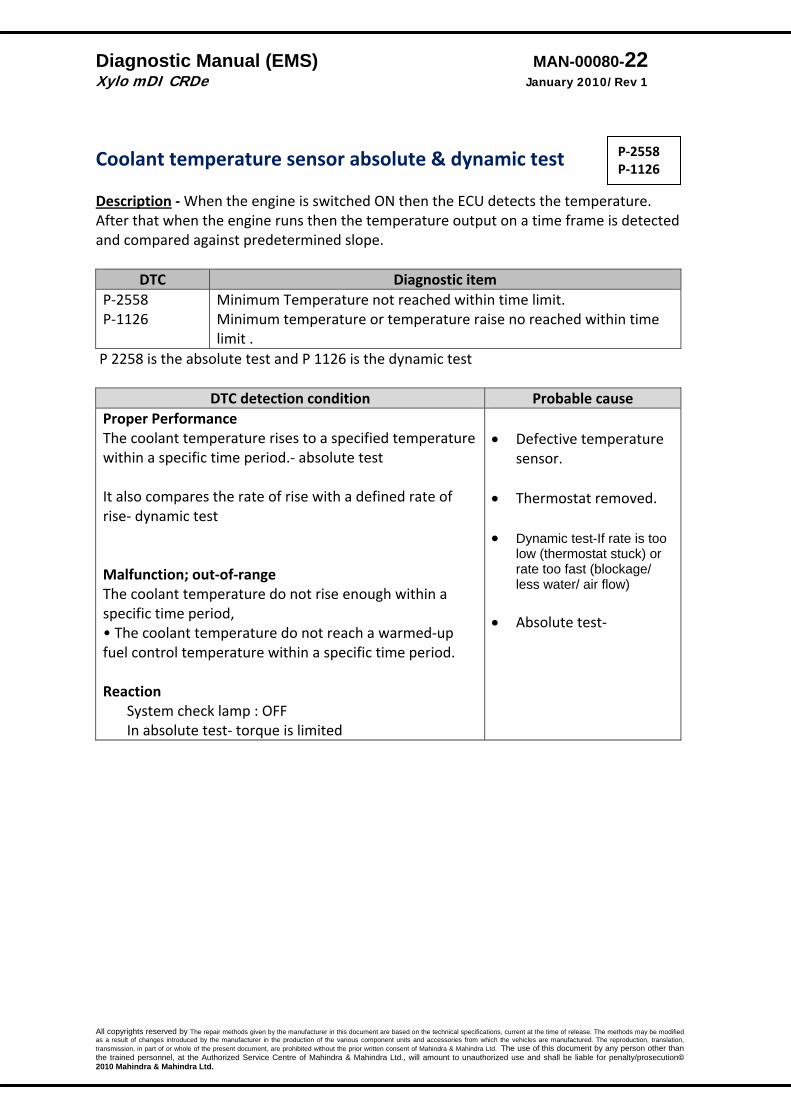
Coolant temperature sensor absolute & dynamic test Description ‐ When the engine is switched ON then the ECU detects the temperature. After that when the engine runs then the temperature output on a time frame is detected and compared against predetermined slope.
DTC Diagnostic item P‐2558 P‐1126
Minimum Temperature not reached within time limit. Minimum temperature or temperature raise no reached within time limit .
P 2258 is the absolute test and P 1126 is the dynamic test
DTC detection condition Probable cause Proper Performance The coolant temperature rises to a specified temperature within a specific time period.‐ absolute test It also compares the rate of rise with a defined rate of rise‐ dynamic test Malfunction; out‐of‐range The coolant temperature do not rise enough within a specific time period, • The coolant temperature do not reach a warmed‐up fuel control temperature within a specific time period. Reaction
System check lamp : OFF In absolute test‐ torque is limited
• Defective temperature
sensor. • Thermostat removed.
• Dynamic test-If rate is too
low (thermostat stuck) or rate too fast (blockage/ less water/ air flow)
• Absolute test‐
P‐2558 P‐1126

Diagnostic Manual (EMS) MAN-00080-23 Xylo mDI CRDe January 2010/Rev 1
All copyrights reserved by The repair methods given by the manufacturer in this document are based on the technical specifications, current at the time of release. The methods may be modified as a result of changes introduced by the manufacturer in the production of the various component units and accessories from which the vehicles are manufactured. The reproduction, translation, transmission, in part of or whole of the present document, are prohibited without the prior written consent of Mahindra & Mahindra Ltd. The use of this document by any person other than the trained personnel, at the Authorized Service Centre of Mahindra & Mahindra Ltd., will amount to unauthorized use and shall be liable for penalty/prosecution© 2010 Mahindra & Mahindra Ltd.
Test Procedure ‐
P‐2558 P‐1126
OK
Fit a new good thermostat
Check if thermostat opening is OK Not Ok Replace
Present
Remove the connector of the temperature sensor
Not Ok
Replace the temperature sensor
Not Present
Check if the thermostat present
Ok
Check for any airflow blockage/ water level less, water pump seizure, water line blockage
Rectify
Diagnostic Manual (EMS) MAN-00080-24 Xylo mDI CRDe January 2010/Rev 1
All copyrights reserved by The repair methods given by the manufacturer in this document are based on the technical specifications, current at the time of release. The methods may be modified as a result of changes introduced by the manufacturer in the production of the various component units and accessories from which the vehicles are manufactured. The reproduction, translation, transmission, in part of or whole of the present document, are prohibited without the prior written consent of Mahindra & Mahindra Ltd. The use of this document by any person other than the trained personnel, at the Authorized Service Centre of Mahindra & Mahindra Ltd., will amount to unauthorized use and shall be liable for penalty/prosecution© 2010 Mahindra & Mahindra Ltd.
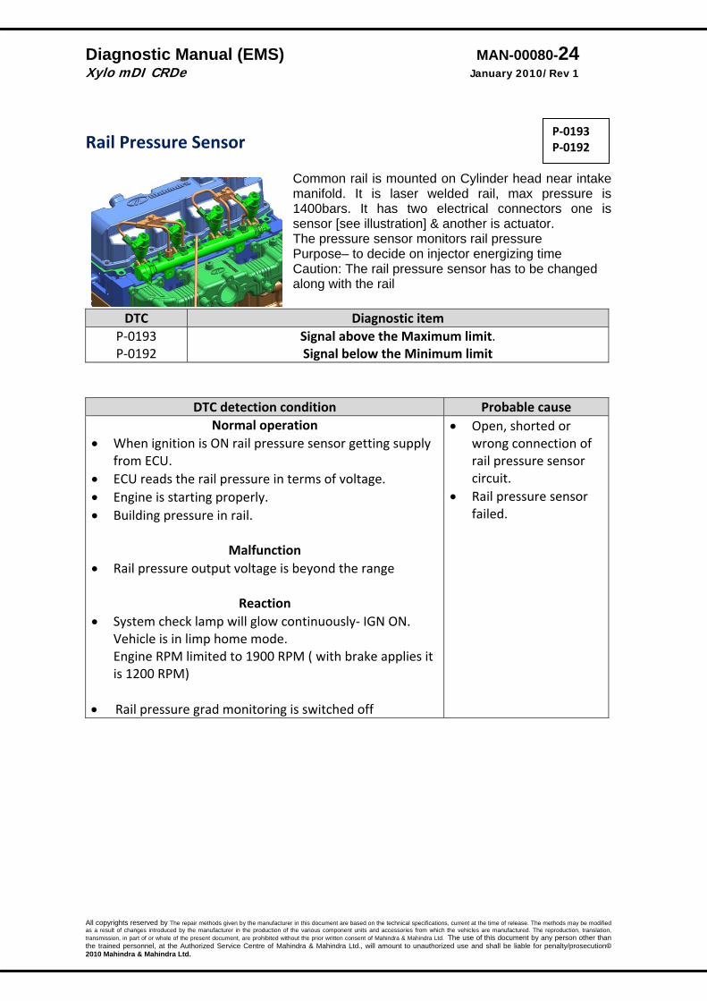
Rail Pressure Sensor
Common rail is mounted on Cylinder head near intake manifold. It is laser welded rail, max pressure is 1400bars. It has two electrical connectors one is sensor [see illustration] & another is actuator. The pressure sensor monitors rail pressure Purpose– to decide on injector energizing time Caution: The rail pressure sensor has to be changed along with the rail
DTC Diagnostic item P‐0193 P‐0192
Signal above the Maximum limit. Signal below the Minimum limit
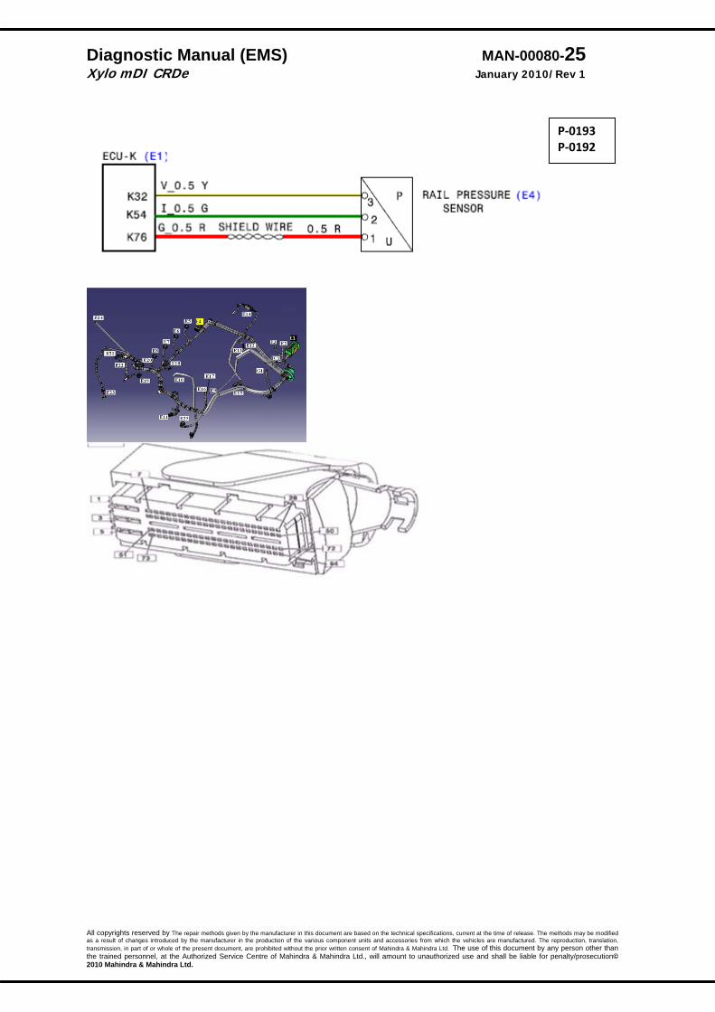
DTC detection condition Probable cause Normal operation
• When ignition is ON rail pressure sensor getting supply from ECU.
• ECU reads the rail pressure in terms of voltage. • Engine is starting properly. • Building pressure in rail.
Malfunction
• Rail pressure output voltage is beyond the range
Reaction • System check lamp will glow continuously‐ IGN ON.
Vehicle is in limp home mode. Engine RPM limited to 1900 RPM ( with brake applies it is 1200 RPM)
• Rail pressure grad monitoring is switched off
• Open, shorted or wrong connection of rail pressure sensor circuit.
• Rail pressure sensor failed.
P‐0193 P‐0192
Diagnostic Manual (EMS) MAN-00080-25 Xylo mDI CRDe January 2010/Rev 1
All copyrights reserved by The repair methods given by the manufacturer in this document are based on the technical specifications, current at the time of release. The methods may be modified as a result of changes introduced by the manufacturer in the production of the various component units and accessories from which the vehicles are manufactured. The reproduction, translation, transmission, in part of or whole of the present document, are prohibited without the prior written consent of Mahindra & Mahindra Ltd. The use of this document by any person other than the trained personnel, at the Authorized Service Centre of Mahindra & Mahindra Ltd., will amount to unauthorized use and shall be liable for penalty/prosecution© 2010 Mahindra & Mahindra Ltd.
P‐0193 P‐0192
Diagnostic Manual (EMS) MAN-00080-26 Xylo mDI CRDe January 2010/Rev 1
All copyrights reserved by The repair methods given by the manufacturer in this document are based on the technical specifications, current at the time of release. The methods may be modified as a result of changes introduced by the manufacturer in the production of the various component units and accessories from which the vehicles are manufactured. The reproduction, translation, transmission, in part of or whole of the present document, are prohibited without the prior written consent of Mahindra & Mahindra Ltd. The use of this document by any person other than the trained personnel, at the Authorized Service Centre of Mahindra & Mahindra Ltd., will amount to unauthorized use and shall be liable for penalty/prosecution© 2010 Mahindra & Mahindra Ltd.
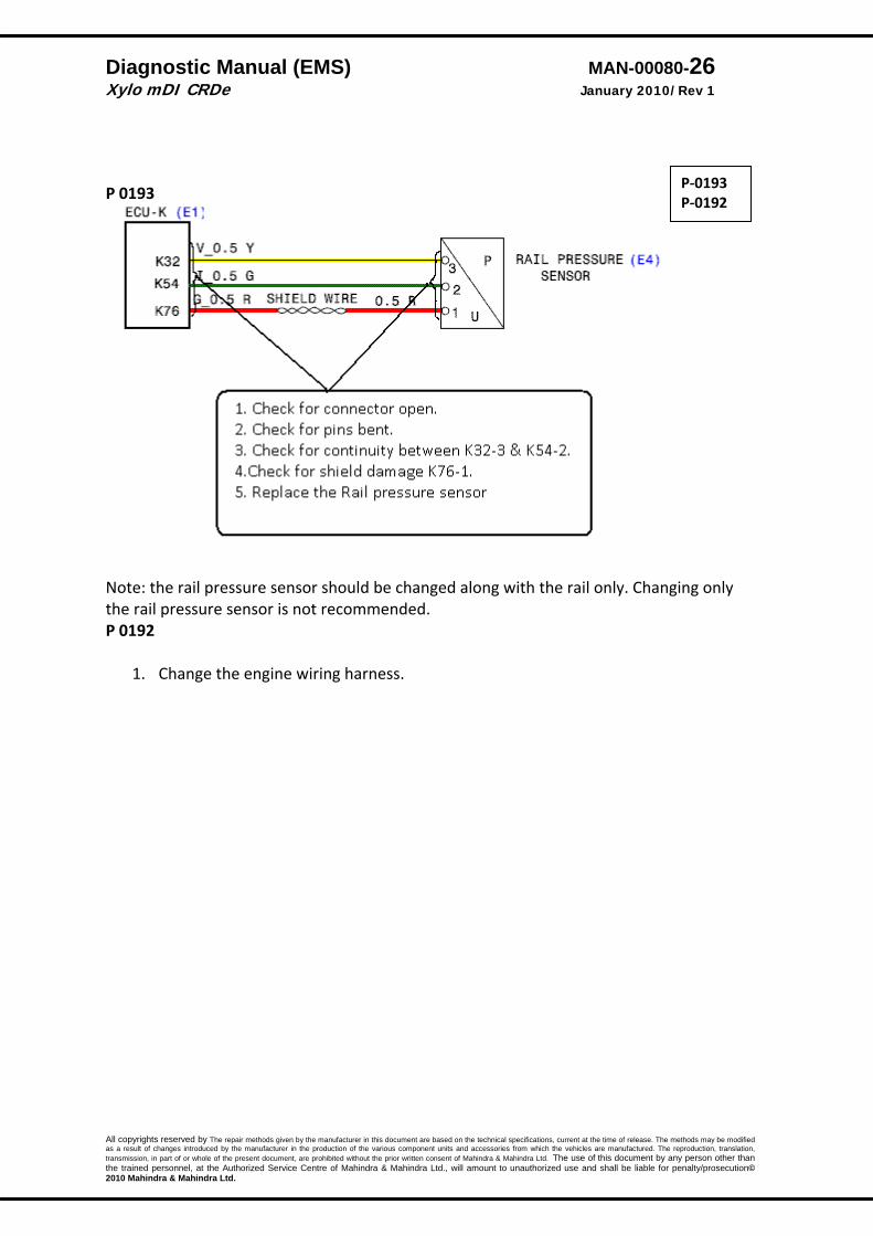
P 0193
Note: the rail pressure sensor should be changed along with the rail only. Changing only the rail pressure sensor is not recommended. P 0192
1. Change the engine wiring harness.
P‐0193 P‐0192

Diagnostic Manual (EMS) MAN-00080-27 Xylo mDI CRDe January 2010/Rev 1
All copyrights reserved by The repair methods given by the manufacturer in this document are based on the technical specifications, current at the time of release. The methods may be modified as a result of changes introduced by the manufacturer in the production of the various component units and accessories from which the vehicles are manufactured. The reproduction, translation, transmission, in part of or whole of the present document, are prohibited without the prior written consent of Mahindra & Mahindra Ltd. The use of this document by any person other than the trained personnel, at the Authorized Service Centre of Mahindra & Mahindra Ltd., will amount to unauthorized use and shall be liable for penalty/prosecution© 2010 Mahindra & Mahindra Ltd.
Rail pressure sensor offset monitoring
DTC Diagnostic item P‐1190 Rail pressure offset – above Max limit
DTC detection condition Probable cause Normal operation
• The offset is monitored during after run • The raw value of the rail pressure is within the limits in
the predefined time
Malfunction • Rail pressure raw voltage value during the overrun
period is above the max set point.
Reaction • Check lamp will glow continuously. • Engine will be in the limp home from the next driving
cycle and can be driven at 1200 RPM only
• Blocked or kinked return line.
• Rail pressure sensor failed.
1. Check and rectify the fuel return line for any kinks, blockages. 2. Change the rail assembly along with the RPS. 3. Clear the errors and verify.
P‐1190
Diagnostic Manual (EMS) MAN-00080-28 Xylo mDI CRDe January 2010/Rev 1
All copyrights reserved by The repair methods given by the manufacturer in this document are based on the technical specifications, current at the time of release. The methods may be modified as a result of changes introduced by the manufacturer in the production of the various component units and accessories from which the vehicles are manufactured. The reproduction, translation, transmission, in part of or whole of the present document, are prohibited without the prior written consent of Mahindra & Mahindra Ltd. The use of this document by any person other than the trained personnel, at the Authorized Service Centre of Mahindra & Mahindra Ltd., will amount to unauthorized use and shall be liable for penalty/prosecution© 2010 Mahindra & Mahindra Ltd.
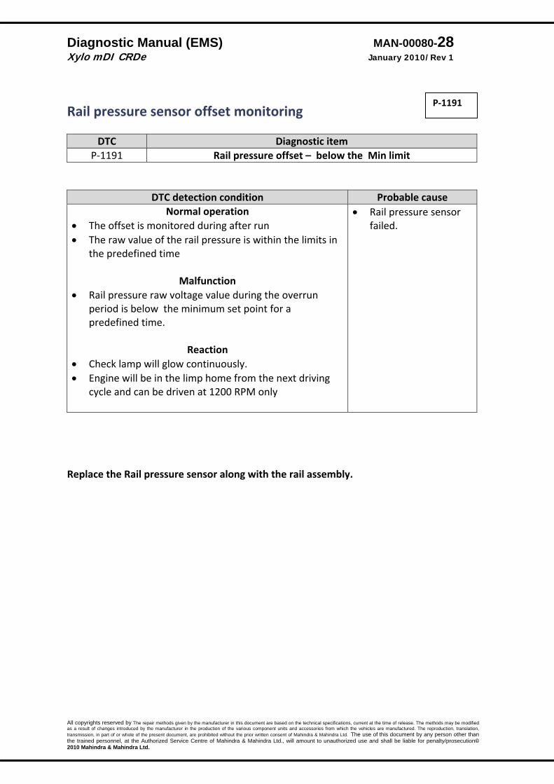
Rail pressure sensor offset monitoring
DTC Diagnostic item P‐1191 Rail pressure offset – below the Min limit
DTC detection condition Probable cause Normal operation
• The offset is monitored during after run • The raw value of the rail pressure is within the limits in
the predefined time
Malfunction • Rail pressure raw voltage value during the overrun
period is below the minimum set point for a predefined time.
Reaction • Check lamp will glow continuously. • Engine will be in the limp home from the next driving
cycle and can be driven at 1200 RPM only
• Rail pressure sensor failed.
Replace the Rail pressure sensor along with the rail assembly.
P‐1191
Diagnostic Manual (EMS) MAN-00080-29 Xylo mDI CRDe January 2010/Rev 1
All copyrights reserved by The repair methods given by the manufacturer in this document are based on the technical specifications, current at the time of release. The methods may be modified as a result of changes introduced by the manufacturer in the production of the various component units and accessories from which the vehicles are manufactured. The reproduction, translation, transmission, in part of or whole of the present document, are prohibited without the prior written consent of Mahindra & Mahindra Ltd. The use of this document by any person other than the trained personnel, at the Authorized Service Centre of Mahindra & Mahindra Ltd., will amount to unauthorized use and shall be liable for penalty/prosecution© 2010 Mahindra & Mahindra Ltd.
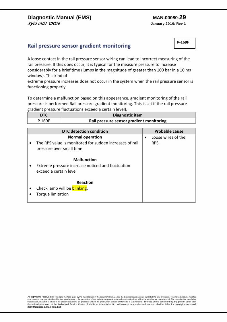
Rail pressure sensor gradient monitoring A loose contact in the rail pressure sensor wiring can lead to incorrect measuring of the rail pressure. If this does occur, it is typical for the measure pressure to increase considerably for a brief time (jumps in the magnitude of greater than 100 bar in a 10 ms window). This kind of extreme pressure increases does not occur in the system when the rail pressure sensor is functioning properly. To determine a malfunction based on this appearance, gradient monitoring of the rail pressure is performed Rail pressure gradient monitoring. This is set if the rail pressure gradient pressure fluctuations exceed a certain level).
DTC Diagnostic item P 169F Rail pressure sensor gradient monitoring
DTC detection condition Probable cause
Normal operation • The RPS value is monitored for sudden increases of rail
pressure over small time
Malfunction • Extreme pressure increase noticed and fluctuation
exceed a certain level
Reaction • Check lamp will be blinking. • Torque limitation
• Loose wires of the RPS.
P‐169F

Diagnostic Manual (EMS) MAN-00080-30 Xylo mDI CRDe January 2010/Rev 1
All copyrights reserved by The repair methods given by the manufacturer in this document are based on the technical specifications, current at the time of release. The methods may be modified as a result of changes introduced by the manufacturer in the production of the various component units and accessories from which the vehicles are manufactured. The reproduction, translation, transmission, in part of or whole of the present document, are prohibited without the prior written consent of Mahindra & Mahindra Ltd. The use of this document by any person other than the trained personnel, at the Authorized Service Centre of Mahindra & Mahindra Ltd., will amount to unauthorized use and shall be liable for penalty/prosecution© 2010 Mahindra & Mahindra Ltd.
Trouble Shooting
Diagnostic Manual (EMS) MAN-00080-31 Xylo mDI CRDe January 2010/Rev 1
All copyrights reserved by The repair methods given by the manufacturer in this document are based on the technical specifications, current at the time of release. The methods may be modified as a result of changes introduced by the manufacturer in the production of the various component units and accessories from which the vehicles are manufactured. The reproduction, translation, transmission, in part of or whole of the present document, are prohibited without the prior written consent of Mahindra & Mahindra Ltd. The use of this document by any person other than the trained personnel, at the Authorized Service Centre of Mahindra & Mahindra Ltd., will amount to unauthorized use and shall be liable for penalty/prosecution© 2010 Mahindra & Mahindra Ltd.
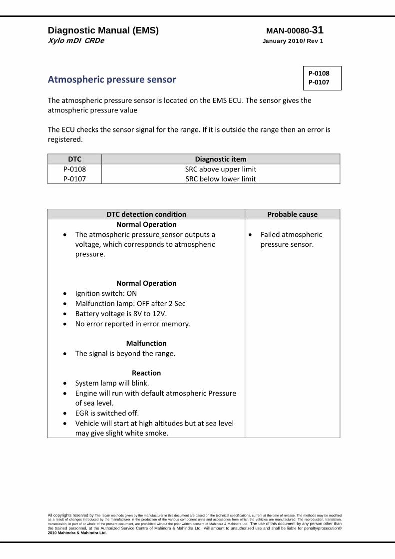
Atmospheric pressure sensor The atmospheric pressure sensor is located on the EMS ECU. The sensor gives the atmospheric pressure value The ECU checks the sensor signal for the range. If it is outside the range then an error is registered.
DTC Diagnostic item P‐0108 P‐0107
SRC above upper limit SRC below lower limit
DTC detection condition Probable cause Normal Operation
• The atmospheric pressure sensor outputs a voltage, which corresponds to atmospheric pressure.
Normal Operation • Ignition switch: ON • Malfunction lamp: OFF after 2 Sec • Battery voltage is 8V to 12V. • No error reported in error memory.
Malfunction • The signal is beyond the range.
Reaction
• System lamp will blink. • Engine will run with default atmospheric Pressure
of sea level. • EGR is switched off. • Vehicle will start at high altitudes but at sea level
may give slight white smoke.
• Failed atmospheric
pressure sensor.
P‐0108 P‐0107
Diagnostic Manual (EMS) MAN-00080-32 Xylo mDI CRDe January 2010/Rev 1
All copyrights reserved by The repair methods given by the manufacturer in this document are based on the technical specifications, current at the time of release. The methods may be modified as a result of changes introduced by the manufacturer in the production of the various component units and accessories from which the vehicles are manufactured. The reproduction, translation, transmission, in part of or whole of the present document, are prohibited without the prior written consent of Mahindra & Mahindra Ltd. The use of this document by any person other than the trained personnel, at the Authorized Service Centre of Mahindra & Mahindra Ltd., will amount to unauthorized use and shall be liable for penalty/prosecution© 2010 Mahindra & Mahindra Ltd.
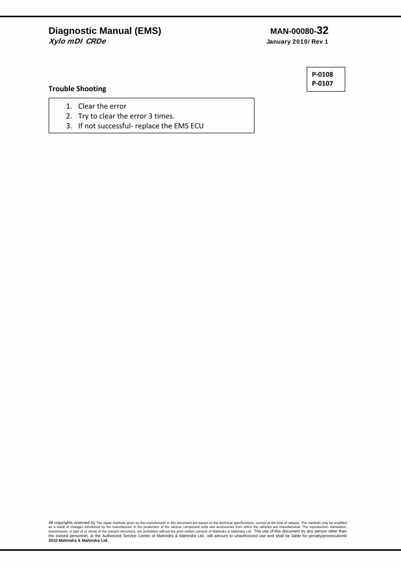
Trouble Shooting
P‐0108 P‐0107
1. Clear the error 2. Try to clear the error 3 times. 3. If not successful‐ replace the EMS ECU

Diagnostic Manual (EMS) MAN-00080-33 Xylo mDI CRDe January 2010/Rev 1
All copyrights reserved by The repair methods given by the manufacturer in this document are based on the technical specifications, current at the time of release. The methods may be modified as a result of changes introduced by the manufacturer in the production of the various component units and accessories from which the vehicles are manufactured. The reproduction, translation, transmission, in part of or whole of the present document, are prohibited without the prior written consent of Mahindra & Mahindra Ltd. The use of this document by any person other than the trained personnel, at the Authorized Service Centre of Mahindra & Mahindra Ltd., will amount to unauthorized use and shall be liable for penalty/prosecution© 2010 Mahindra & Mahindra Ltd.
Air Flow
P‐0335 P‐0336

Diagnostic Manual (EMS) MAN-00080-34 Xylo mDI CRDe January 2010/Rev 1
All copyrights reserved by The repair methods given by the manufacturer in this document are based on the technical specifications, current at the time of release. The methods may be modified as a result of changes introduced by the manufacturer in the production of the various component units and accessories from which the vehicles are manufactured. The reproduction, translation, transmission, in part of or whole of the present document, are prohibited without the prior written consent of Mahindra & Mahindra Ltd. The use of this document by any person other than the trained personnel, at the Authorized Service Centre of Mahindra & Mahindra Ltd., will amount to unauthorized use and shall be liable for penalty/prosecution© 2010 Mahindra & Mahindra Ltd.
Air Flow Description ‐ Mass air flow rate is measured by detection of heat transfer from a hot film probe because the change of the mass air flow rate causes change in the amount of heat being transferred from the hot film probe surface to the air flow. The airflow sensor generates a pulse so it repeatedly opens and closes between the 5V voltage supplied from the engine control module. This results in the change of the temperature of the hot film probe and in the change of resistance.
DTC Diagnostic item P‐0103 P‐0102
Voltage above upper Limit Voltage below lower Limit
DTC detection condition Probable cause
Normal Operation • The HFM sensor outputs a voltage, which
corresponds to the intake airflow. • The ECU checks whether this voltage is within a
specified range. Normal Operating Requirements
• Ignition switch: ON • Malfunction lamp: OFF after 2 Sec • Battery voltage is 8V‐16V or more.
Malfunction • The sensor output voltage has continued to be 5V
or higher. • The sensor output voltage has continued to be
0.5V or lower. Reactions:
• System lamp will continuously blink. Engine will continue to run with default air flow (depending on Speed & Fuelling)
• Open or shorted HFM
sensor circuit, loose or wrong connections.
• Failed HFM sensor.
P‐0103 P‐0102
Diagnostic Manual (EMS) MAN-00080-35 Xylo mDI CRDe January 2010/Rev 1
All copyrights reserved by The repair methods given by the manufacturer in this document are based on the technical specifications, current at the time of release. The methods may be modified as a result of changes introduced by the manufacturer in the production of the various component units and accessories from which the vehicles are manufactured. The reproduction, translation, transmission, in part of or whole of the present document, are prohibited without the prior written consent of Mahindra & Mahindra Ltd. The use of this document by any person other than the trained personnel, at the Authorized Service Centre of Mahindra & Mahindra Ltd., will amount to unauthorized use and shall be liable for penalty/prosecution© 2010 Mahindra & Mahindra Ltd.
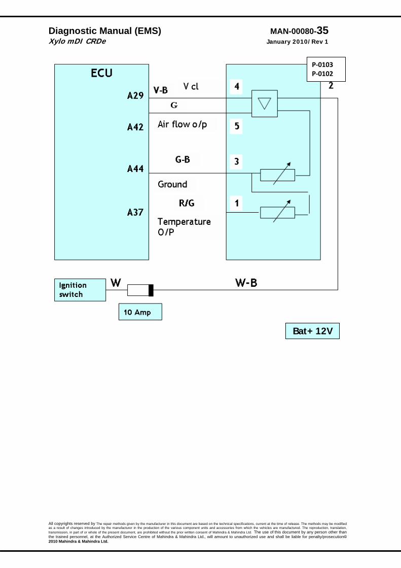
Bat+ 12V
P‐0103 P‐0102

Diagnostic Manual (EMS) MAN-00080-36 Xylo mDI CRDe January 2010/Rev 1
All copyrights reserved by The repair methods given by the manufacturer in this document are based on the technical specifications, current at the time of release. The methods may be modified as a result of changes introduced by the manufacturer in the production of the various component units and accessories from which the vehicles are manufactured. The reproduction, translation, transmission, in part of or whole of the present document, are prohibited without the prior written consent of Mahindra & Mahindra Ltd. The use of this document by any person other than the trained personnel, at the Authorized Service Centre of Mahindra & Mahindra Ltd., will amount to unauthorized use and shall be liable for penalty/prosecution© 2010 Mahindra & Mahindra Ltd.
IC 1
P‐0103 P‐0102
Diagnostic Manual (EMS) MAN-00080-37 Xylo mDI CRDe January 2010/Rev 1
All copyrights reserved by The repair methods given by the manufacturer in this document are based on the technical specifications, current at the time of release. The methods may be modified as a result of changes introduced by the manufacturer in the production of the various component units and accessories from which the vehicles are manufactured. The reproduction, translation, transmission, in part of or whole of the present document, are prohibited without the prior written consent of Mahindra & Mahindra Ltd. The use of this document by any person other than the trained personnel, at the Authorized Service Centre of Mahindra & Mahindra Ltd., will amount to unauthorized use and shall be liable for penalty/prosecution© 2010 Mahindra & Mahindra Ltd.
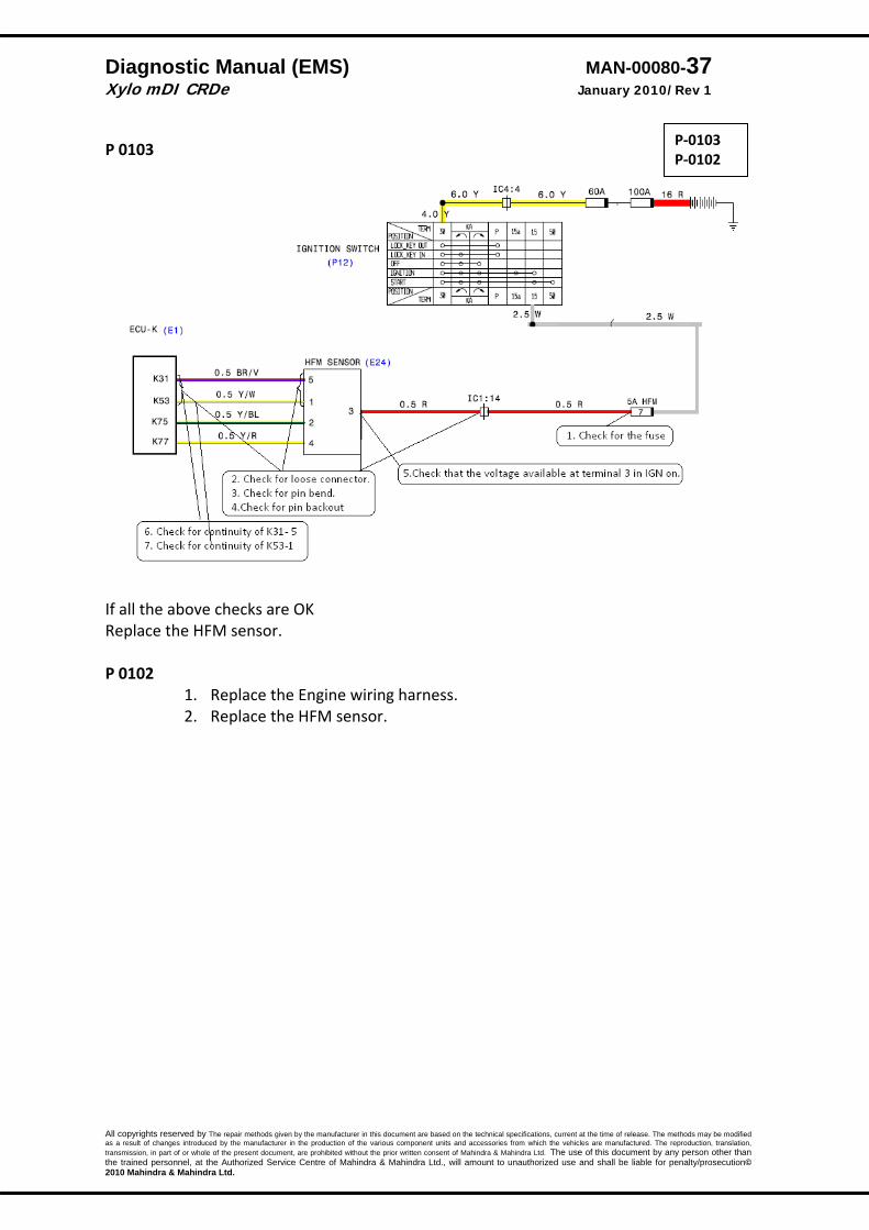
P 0103
If all the above checks are OK Replace the HFM sensor. P 0102
1. Replace the Engine wiring harness. 2. Replace the HFM sensor.
P‐0103 P‐0102
Diagnostic Manual (EMS) MAN-00080-38 Xylo mDI CRDe January 2010/Rev 1
All copyrights reserved by The repair methods given by the manufacturer in this document are based on the technical specifications, current at the time of release. The methods may be modified as a result of changes introduced by the manufacturer in the production of the various component units and accessories from which the vehicles are manufactured. The reproduction, translation, transmission, in part of or whole of the present document, are prohibited without the prior written consent of Mahindra & Mahindra Ltd. The use of this document by any person other than the trained personnel, at the Authorized Service Centre of Mahindra & Mahindra Ltd., will amount to unauthorized use and shall be liable for penalty/prosecution© 2010 Mahindra & Mahindra Ltd.
Air Temperature
P‐0113 P‐0112

Diagnostic Manual (EMS) MAN-00080-39 Xylo mDI CRDe January 2010/Rev 1
All copyrights reserved by The repair methods given by the manufacturer in this document are based on the technical specifications, current at the time of release. The methods may be modified as a result of changes introduced by the manufacturer in the production of the various component units and accessories from which the vehicles are manufactured. The reproduction, translation, transmission, in part of or whole of the present document, are prohibited without the prior written consent of Mahindra & Mahindra Ltd. The use of this document by any person other than the trained personnel, at the Authorized Service Centre of Mahindra & Mahindra Ltd., will amount to unauthorized use and shall be liable for penalty/prosecution© 2010 Mahindra & Mahindra Ltd.
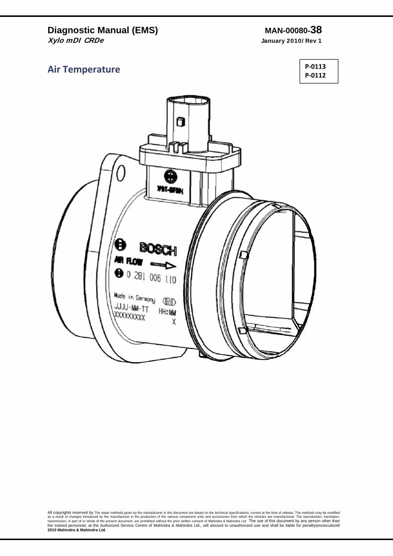
Air Temperature
DTC Diagnostic item P‐0113 P‐0112
Voltage above upper limit. Voltage below lower limit.
Description: The function acquires the raw voltage of the induction air temperature. The raw value is linearised and monitored for compliance with the signal range. The sensor is mounted in HFM.
DTC detection condition Probable cause Normal Operation
• The HFM temperature sensor outputs a voltage, which corresponds to the temperature of intake airflow.
• The ECU checks whether this voltage is within a specified range.
Normal Operating Requirements
• Ignition switch: ON • Malfunction lamp: OFF after 2 Sec • Battery voltage is 8V –16 V.
Malfunction • The sensor output voltage has continued to be 5V
or higher. • The sensor output voltage has continued to be 0.2
V or lower. Reactions
• Engine will run with default air temp of 20 Degrees Centigrade
• System lamp status for this error is blinking.
• Open or shorted HFM
temperature sensor circuit, loose or wrong connections.
• Failed HFM
temperature sensor.
P‐0113 P‐0112
Diagnostic Manual (EMS) MAN-00080-40 Xylo mDI CRDe January 2010/Rev 1
All copyrights reserved by The repair methods given by the manufacturer in this document are based on the technical specifications, current at the time of release. The methods may be modified as a result of changes introduced by the manufacturer in the production of the various component units and accessories from which the vehicles are manufactured. The reproduction, translation, transmission, in part of or whole of the present document, are prohibited without the prior written consent of Mahindra & Mahindra Ltd. The use of this document by any person other than the trained personnel, at the Authorized Service Centre of Mahindra & Mahindra Ltd., will amount to unauthorized use and shall be liable for penalty/prosecution© 2010 Mahindra & Mahindra Ltd.
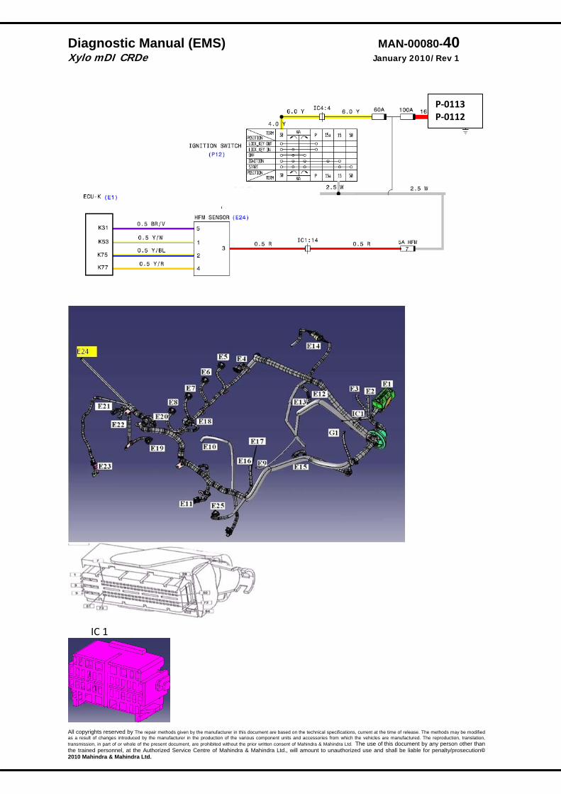
IC 1
P‐0113 P‐0112

Diagnostic Manual (EMS) MAN-00080-41 Xylo mDI CRDe January 2010/Rev 1
All copyrights reserved by The repair methods given by the manufacturer in this document are based on the technical specifications, current at the time of release. The methods may be modified as a result of changes introduced by the manufacturer in the production of the various component units and accessories from which the vehicles are manufactured. The reproduction, translation, transmission, in part of or whole of the present document, are prohibited without the prior written consent of Mahindra & Mahindra Ltd. The use of this document by any person other than the trained personnel, at the Authorized Service Centre of Mahindra & Mahindra Ltd., will amount to unauthorized use and shall be liable for penalty/prosecution© 2010 Mahindra & Mahindra Ltd.
P 0113
P 0112
1. Replace the Engine wiring harness. 2. Replace the HFM sensor.
P‐0113 P‐0112
Diagnostic Manual (EMS) MAN-00080-42 Xylo mDI CRDe January 2010/Rev 1
All copyrights reserved by The repair methods given by the manufacturer in this document are based on the technical specifications, current at the time of release. The methods may be modified as a result of changes introduced by the manufacturer in the production of the various component units and accessories from which the vehicles are manufactured. The reproduction, translation, transmission, in part of or whole of the present document, are prohibited without the prior written consent of Mahindra & Mahindra Ltd. The use of this document by any person other than the trained personnel, at the Authorized Service Centre of Mahindra & Mahindra Ltd., will amount to unauthorized use and shall be liable for penalty/prosecution© 2010 Mahindra & Mahindra Ltd.
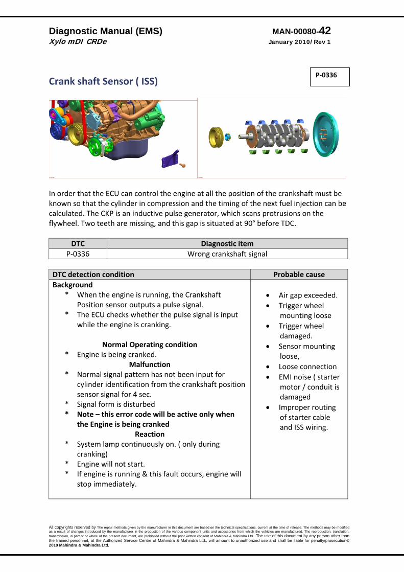
Crank shaft Sensor ( ISS)
In order that the ECU can control the engine at all the position of the crankshaft must be known so that the cylinder in compression and the timing of the next fuel injection can be calculated. The CKP is an inductive pulse generator, which scans protrusions on the flywheel. Two teeth are missing, and this gap is situated at 90° before TDC.
DTC Diagnostic item P‐0336 Wrong crankshaft signal
DTC detection condition Probable cause Background
* When the engine is running, the Crankshaft Position sensor outputs a pulse signal.
* The ECU checks whether the pulse signal is input while the engine is cranking.
Normal Operating condition
* Engine is being cranked. Malfunction
* Normal signal pattern has not been input for cylinder identification from the crankshaft position sensor signal for 4 sec.
* Signal form is disturbed * Note – this error code will be active only when
the Engine is being cranked Reaction
* System lamp continuously on. ( only during cranking)
* Engine will not start. * If engine is running & this fault occurs, engine will
stop immediately.
• Air gap exceeded. • Trigger wheel
mounting loose • Trigger wheel
damaged. • Sensor mounting
loose, • Loose connection • EMI noise ( starter
motor / conduit is damaged
• Improper routing of starter cable and ISS wiring.
P‐0336

Diagnostic Manual (EMS) MAN-00080-43 Xylo mDI CRDe January 2010/Rev 1
All copyrights reserved by The repair methods given by the manufacturer in this document are based on the technical specifications, current at the time of release. The methods may be modified as a result of changes introduced by the manufacturer in the production of the various component units and accessories from which the vehicles are manufactured. The reproduction, translation, transmission, in part of or whole of the present document, are prohibited without the prior written consent of Mahindra & Mahindra Ltd. The use of this document by any person other than the trained personnel, at the Authorized Service Centre of Mahindra & Mahindra Ltd., will amount to unauthorized use and shall be liable for penalty/prosecution© 2010 Mahindra & Mahindra Ltd.
P‐0336

Diagnostic Manual (EMS) MAN-00080-44 Xylo mDI CRDe January 2010/Rev 1
All copyrights reserved by The repair methods given by the manufacturer in this document are based on the technical specifications, current at the time of release. The methods may be modified as a result of changes introduced by the manufacturer in the production of the various component units and accessories from which the vehicles are manufactured. The reproduction, translation, transmission, in part of or whole of the present document, are prohibited without the prior written consent of Mahindra & Mahindra Ltd. The use of this document by any person other than the trained personnel, at the Authorized Service Centre of Mahindra & Mahindra Ltd., will amount to unauthorized use and shall be liable for penalty/prosecution© 2010 Mahindra & Mahindra Ltd.
If electrically all OK then look at mechanical parts.
P‐0336
Diagnostic Manual (EMS) MAN-00080-45 Xylo mDI CRDe January 2010/Rev 1
All copyrights reserved by The repair methods given by the manufacturer in this document are based on the technical specifications, current at the time of release. The methods may be modified as a result of changes introduced by the manufacturer in the production of the various component units and accessories from which the vehicles are manufactured. The reproduction, translation, transmission, in part of or whole of the present document, are prohibited without the prior written consent of Mahindra & Mahindra Ltd. The use of this document by any person other than the trained personnel, at the Authorized Service Centre of Mahindra & Mahindra Ltd., will amount to unauthorized use and shall be liable for penalty/prosecution© 2010 Mahindra & Mahindra Ltd.
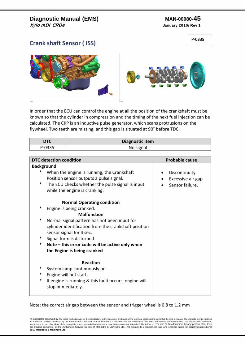
Crank shaft Sensor ( ISS)
In order that the ECU can control the engine at all the position of the crankshaft must be known so that the cylinder in compression and the timing of the next fuel injection can be calculated. The CKP is an inductive pulse generator, which scans protrusions on the flywheel. Two teeth are missing, and this gap is situated at 90° before TDC.
DTC Diagnostic item P‐0335 No signal
DTC detection condition Probable cause Background
* When the engine is running, the Crankshaft Position sensor outputs a pulse signal.
* The ECU checks whether the pulse signal is input while the engine is cranking.
Normal Operating condition
* Engine is being cranked. Malfunction
* Normal signal pattern has not been input for cylinder identification from the crankshaft position sensor signal for 4 sec.
* Signal form is disturbed * Note – this error code will be active only when
the Engine is being cranked
Reaction * System lamp continuously on. * Engine will not start. * If engine is running & this fault occurs, engine will
stop immediately.
• Discontinuity • Excessive air gap • Sensor failure.
Note: the correct air gap between the sensor and trigger wheel is 0.8 to 1.2 mm
P‐0335

Diagnostic Manual (EMS) MAN-00080-46 Xylo mDI CRDe January 2010/Rev 1
All copyrights reserved by The repair methods given by the manufacturer in this document are based on the technical specifications, current at the time of release. The methods may be modified as a result of changes introduced by the manufacturer in the production of the various component units and accessories from which the vehicles are manufactured. The reproduction, translation, transmission, in part of or whole of the present document, are prohibited without the prior written consent of Mahindra & Mahindra Ltd. The use of this document by any person other than the trained personnel, at the Authorized Service Centre of Mahindra & Mahindra Ltd., will amount to unauthorized use and shall be liable for penalty/prosecution© 2010 Mahindra & Mahindra Ltd.
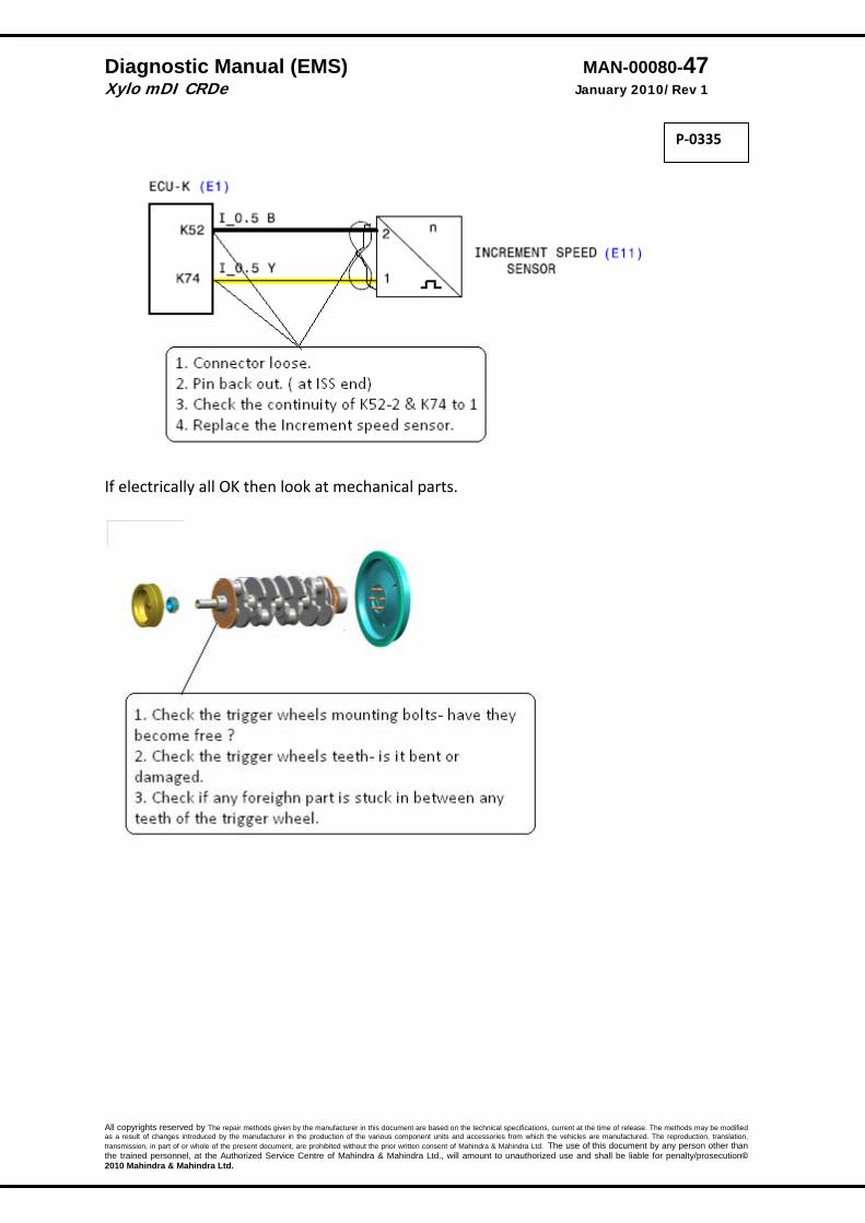
P‐0335
Diagnostic Manual (EMS) MAN-00080-47 Xylo mDI CRDe January 2010/Rev 1
All copyrights reserved by The repair methods given by the manufacturer in this document are based on the technical specifications, current at the time of release. The methods may be modified as a result of changes introduced by the manufacturer in the production of the various component units and accessories from which the vehicles are manufactured. The reproduction, translation, transmission, in part of or whole of the present document, are prohibited without the prior written consent of Mahindra & Mahindra Ltd. The use of this document by any person other than the trained personnel, at the Authorized Service Centre of Mahindra & Mahindra Ltd., will amount to unauthorized use and shall be liable for penalty/prosecution© 2010 Mahindra & Mahindra Ltd.
If electrically all OK then look at mechanical parts.
P‐0335

Diagnostic Manual (EMS) MAN-00080-48 Xylo mDI CRDe January 2010/Rev 1
All copyrights reserved by The repair methods given by the manufacturer in this document are based on the technical specifications, current at the time of release. The methods may be modified as a result of changes introduced by the manufacturer in the production of the various component units and accessories from which the vehicles are manufactured. The reproduction, translation, transmission, in part of or whole of the present document, are prohibited without the prior written consent of Mahindra & Mahindra Ltd. The use of this document by any person other than the trained personnel, at the Authorized Service Centre of Mahindra & Mahindra Ltd., will amount to unauthorized use and shall be liable for penalty/prosecution© 2010 Mahindra & Mahindra Ltd.
Camshaft speed sensor
DTC Diagnostic item P‐0340 P‐0341
No camshaft signal Wrong camshaft signal
The Hall effect camshaft position sensor senses the Top dead center (TDC) point of the # 1 cylinder in the compression stroke. Which allows the ECU to determine when to start the injection. The trigger is mounted in the camshaft
DTC detection condition Probable cause
Normal Operation * When the engine is running, the Camshaft Position
sensor outputs a pulse signal. * The ECU checks whether the pulse signal is input.
Malfunction * Normal signal pattern has not been input for
cylinder identification from the camshaft position sensor signal for 4 sec. (Engine should be cranked to check this error).
* Note – this error code will be active only when the Engine is being cranked
Reaction
* Engine will not start * System lamp will be continuously on. * If this failure occurs when the engine is running
then engine will keep on running. It will not allow the engine to start.
* Open or shorted
camshaft position sensor circuit, loose or wrong connection.
* Camshaft Position sensor malfunction.
Note: the correct air gap between the sensor and trigger wheel is 0.8 to 1.2 mm
P‐0340 P‐0341

Diagnostic Manual (EMS) MAN-00080-49 Xylo mDI CRDe January 2010/Rev 1
All copyrights reserved by The repair methods given by the manufacturer in this document are based on the technical specifications, current at the time of release. The methods may be modified as a result of changes introduced by the manufacturer in the production of the various component units and accessories from which the vehicles are manufactured. The reproduction, translation, transmission, in part of or whole of the present document, are prohibited without the prior written consent of Mahindra & Mahindra Ltd. The use of this document by any person other than the trained personnel, at the Authorized Service Centre of Mahindra & Mahindra Ltd., will amount to unauthorized use and shall be liable for penalty/prosecution© 2010 Mahindra & Mahindra Ltd.

Diagnostic Manual (EMS) MAN-00080-50 Xylo mDI CRDe January 2010/Rev 1
All copyrights reserved by The repair methods given by the manufacturer in this document are based on the technical specifications, current at the time of release. The methods may be modified as a result of changes introduced by the manufacturer in the production of the various component units and accessories from which the vehicles are manufactured. The reproduction, translation, transmission, in part of or whole of the present document, are prohibited without the prior written consent of Mahindra & Mahindra Ltd. The use of this document by any person other than the trained personnel, at the Authorized Service Centre of Mahindra & Mahindra Ltd., will amount to unauthorized use and shall be liable for penalty/prosecution© 2010 Mahindra & Mahindra Ltd.
P 0340‐ No signal
P 0341
P‐0340 P‐0341
Diagnostic Manual (EMS) MAN-00080-51 Xylo mDI CRDe January 2010/Rev 1
All copyrights reserved by The repair methods given by the manufacturer in this document are based on the technical specifications, current at the time of release. The methods may be modified as a result of changes introduced by the manufacturer in the production of the various component units and accessories from which the vehicles are manufactured. The reproduction, translation, transmission, in part of or whole of the present document, are prohibited without the prior written consent of Mahindra & Mahindra Ltd. The use of this document by any person other than the trained personnel, at the Authorized Service Centre of Mahindra & Mahindra Ltd., will amount to unauthorized use and shall be liable for penalty/prosecution© 2010 Mahindra & Mahindra Ltd.
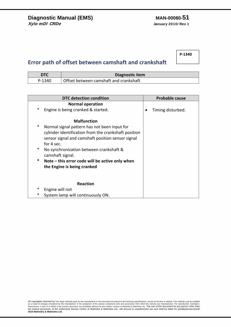
Error path of offset between camshaft and crankshaft
DTC Diagnostic item P‐1340 Offset between camshaft and crankshaft
DTC detection condition Probable cause Normal operation
* Engine is being cranked & started.
Malfunction * Normal signal pattern has not been input for
cylinder identification from the crankshaft position sensor signal and camshaft position sensor signal for 4 sec.
* No synchronization between crankshaft & camshaft signal.
* Note – this error code will be active only when the Engine is being cranked
Reaction
* Engine will not * System lamp will continuously ON.
• Timing disturbed.
P‐1340

Diagnostic Manual (EMS) MAN-00080-52 Xylo mDI CRDe January 2010/Rev 1
All copyrights reserved by The repair methods given by the manufacturer in this document are based on the technical specifications, current at the time of release. The methods may be modified as a result of changes introduced by the manufacturer in the production of the various component units and accessories from which the vehicles are manufactured. The reproduction, translation, transmission, in part of or whole of the present document, are prohibited without the prior written consent of Mahindra & Mahindra Ltd. The use of this document by any person other than the trained personnel, at the Authorized Service Centre of Mahindra & Mahindra Ltd., will amount to unauthorized use and shall be liable for penalty/prosecution© 2010 Mahindra & Mahindra Ltd.
6. Check the flywheel mounting bolts is it loose.. 7. Has flywheel been fitted wrongly? 8. Toner wheel rotated. 9. Toner wheel teeth damaged.

Diagnostic Manual (EMS) MAN-00080-53 Xylo mDI CRDe January 2010/Rev 1
All copyrights reserved by The repair methods given by the manufacturer in this document are based on the technical specifications, current at the time of release. The methods may be modified as a result of changes introduced by the manufacturer in the production of the various component units and accessories from which the vehicles are manufactured. The reproduction, translation, transmission, in part of or whole of the present document, are prohibited without the prior written consent of Mahindra & Mahindra Ltd. The use of this document by any person other than the trained personnel, at the Authorized Service Centre of Mahindra & Mahindra Ltd., will amount to unauthorized use and shall be liable for penalty/prosecution© 2010 Mahindra & Mahindra Ltd.
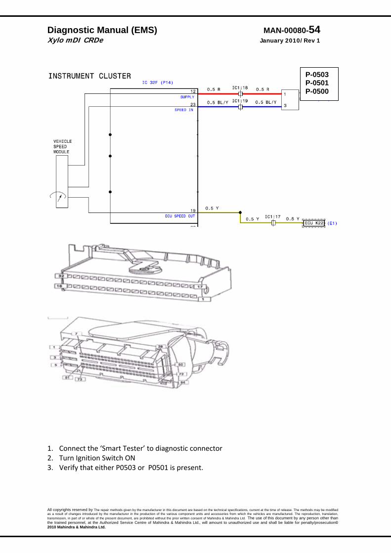
Vehicle Speed Sensor:
DTC Diagnostic item P‐0503 P‐0501 P‐0500
Exceeding of the maximum vehicle speed Vehicle speed not plausible with injection mass and engine speed
Vehicle speed trigger wheel error
DTC detection condition Probable cause Normal Operation
* The vehicle speed sensor outputs a pulse signal while the vehicle is driven.
* The ECU checks whether the pulse signal is present.
Malfunction
* Sensor output voltage has not changed (No pulse signal) for 4 sec.
* This error will not be generated if the clutch signal is not there .
Reaction
∗ All the load dependent function e.g. FBC, ZFC are switched off.
∗ Vehicle may feel jerky while driving.
• Failed vehicle speed
sensor. • Open shorted vehicle‐
speed sensor circuit, loose or wrong connection.
P-0503 P-0501
Diagnostic Manual (EMS) MAN-00080-54 Xylo mDI CRDe January 2010/Rev 1
All copyrights reserved by The repair methods given by the manufacturer in this document are based on the technical specifications, current at the time of release. The methods may be modified as a result of changes introduced by the manufacturer in the production of the various component units and accessories from which the vehicles are manufactured. The reproduction, translation, transmission, in part of or whole of the present document, are prohibited without the prior written consent of Mahindra & Mahindra Ltd. The use of this document by any person other than the trained personnel, at the Authorized Service Centre of Mahindra & Mahindra Ltd., will amount to unauthorized use and shall be liable for penalty/prosecution© 2010 Mahindra & Mahindra Ltd.
1. Connect the ‘Smart Tester’ to diagnostic connector 2. Turn Ignition Switch ON 3. Verify that either P0503 or P0501 is present.
P-0503 P-0501 P-0500

Diagnostic Manual (EMS) MAN-00080-55 Xylo mDI CRDe January 2010/Rev 1
All copyrights reserved by The repair methods given by the manufacturer in this document are based on the technical specifications, current at the time of release. The methods may be modified as a result of changes introduced by the manufacturer in the production of the various component units and accessories from which the vehicles are manufactured. The reproduction, translation, transmission, in part of or whole of the present document, are prohibited without the prior written consent of Mahindra & Mahindra Ltd. The use of this document by any person other than the trained personnel, at the Authorized Service Centre of Mahindra & Mahindra Ltd., will amount to unauthorized use and shall be liable for penalty/prosecution© 2010 Mahindra & Mahindra Ltd.
P 0503
1. Replace the vehicle speed sensor. P 0501
P-0503 P-0501 P-0500
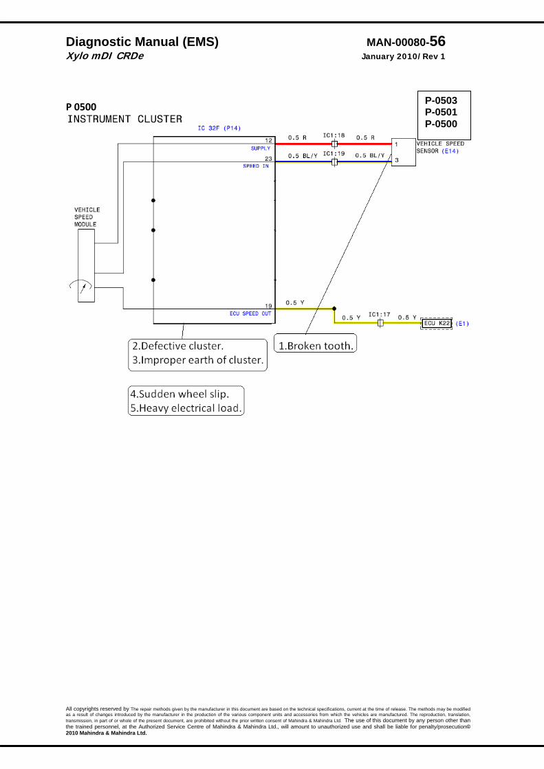
Diagnostic Manual (EMS) MAN-00080-56 Xylo mDI CRDe January 2010/Rev 1
All copyrights reserved by The repair methods given by the manufacturer in this document are based on the technical specifications, current at the time of release. The methods may be modified as a result of changes introduced by the manufacturer in the production of the various component units and accessories from which the vehicles are manufactured. The reproduction, translation, transmission, in part of or whole of the present document, are prohibited without the prior written consent of Mahindra & Mahindra Ltd. The use of this document by any person other than the trained personnel, at the Authorized Service Centre of Mahindra & Mahindra Ltd., will amount to unauthorized use and shall be liable for penalty/prosecution© 2010 Mahindra & Mahindra Ltd.
P 0500
P-0503 P-0501 P-0500
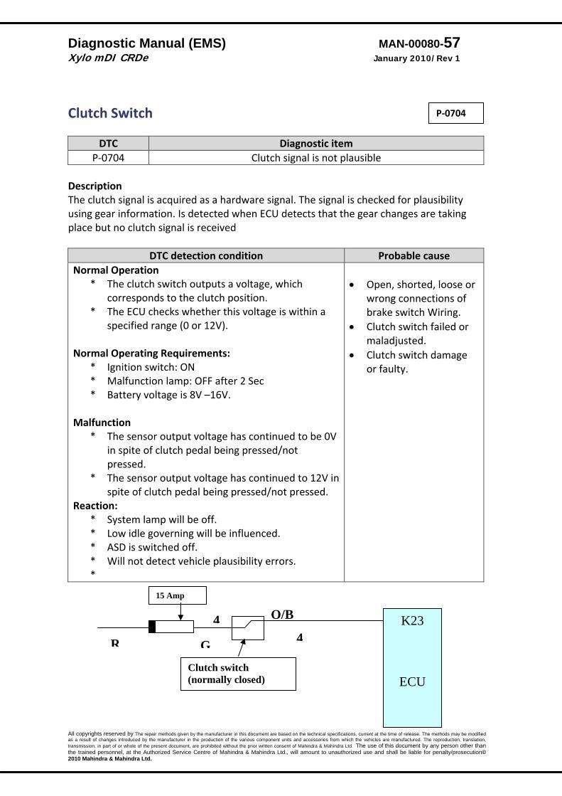
Diagnostic Manual (EMS) MAN-00080-57 Xylo mDI CRDe January 2010/Rev 1
All copyrights reserved by The repair methods given by the manufacturer in this document are based on the technical specifications, current at the time of release. The methods may be modified as a result of changes introduced by the manufacturer in the production of the various component units and accessories from which the vehicles are manufactured. The reproduction, translation, transmission, in part of or whole of the present document, are prohibited without the prior written consent of Mahindra & Mahindra Ltd. The use of this document by any person other than the trained personnel, at the Authorized Service Centre of Mahindra & Mahindra Ltd., will amount to unauthorized use and shall be liable for penalty/prosecution© 2010 Mahindra & Mahindra Ltd.
Clutch Switch
DTC Diagnostic item P‐0704 Clutch signal is not plausible
Description The clutch signal is acquired as a hardware signal. The signal is checked for plausibility using gear information. Is detected when ECU detects that the gear changes are taking place but no clutch signal is received
DTC detection condition Probable cause Normal Operation
* The clutch switch outputs a voltage, which corresponds to the clutch position.
* The ECU checks whether this voltage is within a specified range (0 or 12V).
Normal Operating Requirements:
* Ignition switch: ON * Malfunction lamp: OFF after 2 Sec * Battery voltage is 8V –16V.
Malfunction * The sensor output voltage has continued to be 0V
in spite of clutch pedal being pressed/not pressed.
* The sensor output voltage has continued to 12V in spite of clutch pedal being pressed/not pressed.
Reaction: * System lamp will be off. * Low idle governing will be influenced. * ASD is switched off. * Will not detect vehicle plausibility errors. *
• Open, shorted, loose or
wrong connections of brake switch Wiring.
• Clutch switch failed or maladjusted.
• Clutch switch damage or faulty.
G
O/B 4 K23
ECU
15 Amp
Clutch switch (normally closed)
R 4
P‐0704
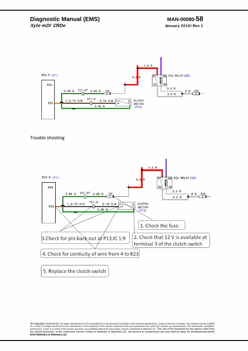
Diagnostic Manual (EMS) MAN-00080-58 Xylo mDI CRDe January 2010/Rev 1
All copyrights reserved by The repair methods given by the manufacturer in this document are based on the technical specifications, current at the time of release. The methods may be modified as a result of changes introduced by the manufacturer in the production of the various component units and accessories from which the vehicles are manufactured. The reproduction, translation, transmission, in part of or whole of the present document, are prohibited without the prior written consent of Mahindra & Mahindra Ltd. The use of this document by any person other than the trained personnel, at the Authorized Service Centre of Mahindra & Mahindra Ltd., will amount to unauthorized use and shall be liable for penalty/prosecution© 2010 Mahindra & Mahindra Ltd.
Trouble shooting
Diagnostic Manual (EMS) MAN-00080-59 Xylo mDI CRDe January 2010/Rev 1
All copyrights reserved by The repair methods given by the manufacturer in this document are based on the technical specifications, current at the time of release. The methods may be modified as a result of changes introduced by the manufacturer in the production of the various component units and accessories from which the vehicles are manufactured. The reproduction, translation, transmission, in part of or whole of the present document, are prohibited without the prior written consent of Mahindra & Mahindra Ltd. The use of this document by any person other than the trained personnel, at the Authorized Service Centre of Mahindra & Mahindra Ltd., will amount to unauthorized use and shall be liable for penalty/prosecution© 2010 Mahindra & Mahindra Ltd.
Brake Switch The function acquires and processes the information via the brake contact and the redundant brake contact. The status message of the brake position is the output.
DTC Diagnostic item P‐1792 Brake signals not plausible
DTC detection condition Probable cause Principle
* The brake switch outputs a voltage, which corresponds to the brake position.
* The ECU checks whether this voltage is within a specified range (0 or 12V).
Normal Operation
* Ignition switch: ON * System lamp: OFF after 2 Sec * Battery voltage is 8V –16V. * In normal condition one brake signal is ON and
other is OFF.
Malfunction * The sensor output voltage has continued to be 0V
in spite of brake pedal being pressed/not pressed * The sensor output voltage has continued to 12V in
spite of brake pedal being pressed/not pressed * Main or redundant switch is not working. * If both the main and redundant signals are the
same then it is taken as plausibility defect. Reaction
* System lamp will be off * Accelerator plausibility error detection stopped. * Under braking condition detection stopped.
• Open, shorted, loose or
wrong connections of brake switch Wiring.
• Brake switch damage or faulty
• Brake switch failed or maladjusted.
.
P‐1792
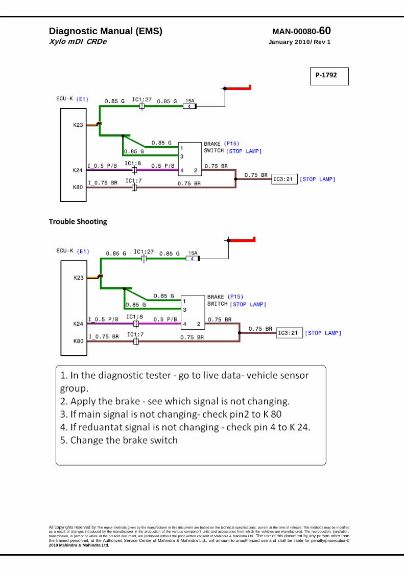
Diagnostic Manual (EMS) MAN-00080-60 Xylo mDI CRDe January 2010/Rev 1
All copyrights reserved by The repair methods given by the manufacturer in this document are based on the technical specifications, current at the time of release. The methods may be modified as a result of changes introduced by the manufacturer in the production of the various component units and accessories from which the vehicles are manufactured. The reproduction, translation, transmission, in part of or whole of the present document, are prohibited without the prior written consent of Mahindra & Mahindra Ltd. The use of this document by any person other than the trained personnel, at the Authorized Service Centre of Mahindra & Mahindra Ltd., will amount to unauthorized use and shall be liable for penalty/prosecution© 2010 Mahindra & Mahindra Ltd.
Trouble Shooting
P‐1792
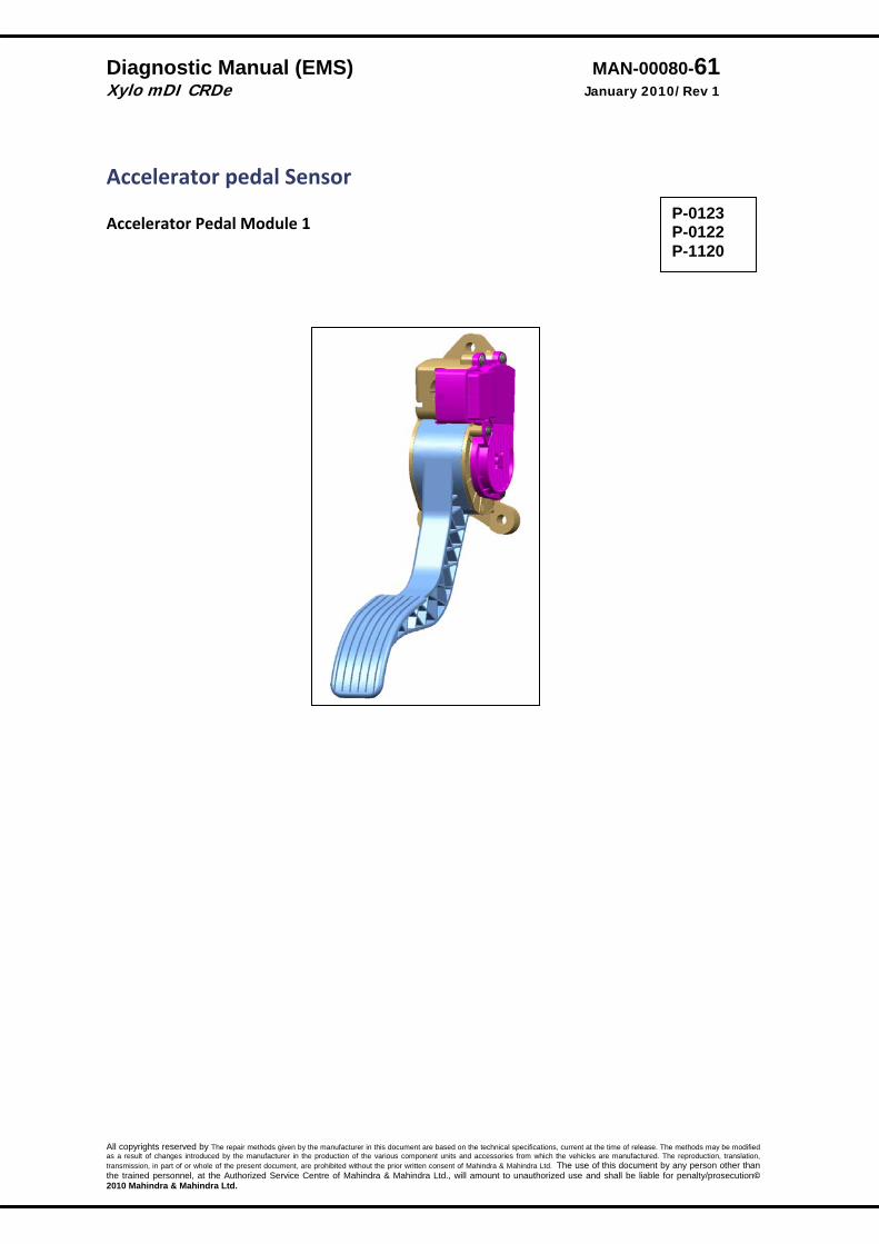
Diagnostic Manual (EMS) MAN-00080-61 Xylo mDI CRDe January 2010/Rev 1
All copyrights reserved by The repair methods given by the manufacturer in this document are based on the technical specifications, current at the time of release. The methods may be modified as a result of changes introduced by the manufacturer in the production of the various component units and accessories from which the vehicles are manufactured. The reproduction, translation, transmission, in part of or whole of the present document, are prohibited without the prior written consent of Mahindra & Mahindra Ltd. The use of this document by any person other than the trained personnel, at the Authorized Service Centre of Mahindra & Mahindra Ltd., will amount to unauthorized use and shall be liable for penalty/prosecution© 2010 Mahindra & Mahindra Ltd.
Accelerator pedal Sensor Accelerator Pedal Module 1
P-0123 P-0122 P-1120

Diagnostic Manual (EMS) MAN-00080-62 Xylo mDI CRDe January 2010/Rev 1
All copyrights reserved by The repair methods given by the manufacturer in this document are based on the technical specifications, current at the time of release. The methods may be modified as a result of changes introduced by the manufacturer in the production of the various component units and accessories from which the vehicles are manufactured. The reproduction, translation, transmission, in part of or whole of the present document, are prohibited without the prior written consent of Mahindra & Mahindra Ltd. The use of this document by any person other than the trained personnel, at the Authorized Service Centre of Mahindra & Mahindra Ltd., will amount to unauthorized use and shall be liable for penalty/prosecution© 2010 Mahindra & Mahindra Ltd.
Accelerator Pedal Module 1 Description: The Accelerator pedal module (APM) mounts in place of accelerator pedal and is connected to the ECU by wires. The APM sensor is a variable resistor (potentiometer) whose resistance changes according to the pedal position. ECU applies a reference voltage to the APM sensor and then measures the voltage that is present on the APM sensor signal circuit. The ECU uses the APM sensor signal for further calculation of fuelling & other engine operational parameters.
DTC Diagnostic item P‐0123 SRC High.
DTC detection condition Probable cause Normal Operation
* The Accelerator pedal module (APM) outputs a voltage, which is proportional to the Position of accelerator pedal.
* The ECU checks whether the voltage output by the Accelerator pedal module is within a specified range. In addition, it checks that the voltage output does not become too large while the engine is in idling.
Proper Performance Sensor output voltage has continued to between 0 to 3.3V, varying accelerator pedal position. Malfunction; out‐of‐range
* With the changing Accelerator pedal position, the sensor output voltage has continued to be 3.3V or 0V.
Reaction:
* Fuelling is controlled‐ pedal travel is more. * The system lamp is continuously on. * Torque Limitation is active.
• Short circuit to ground ( power side or at signal)
P‐0123
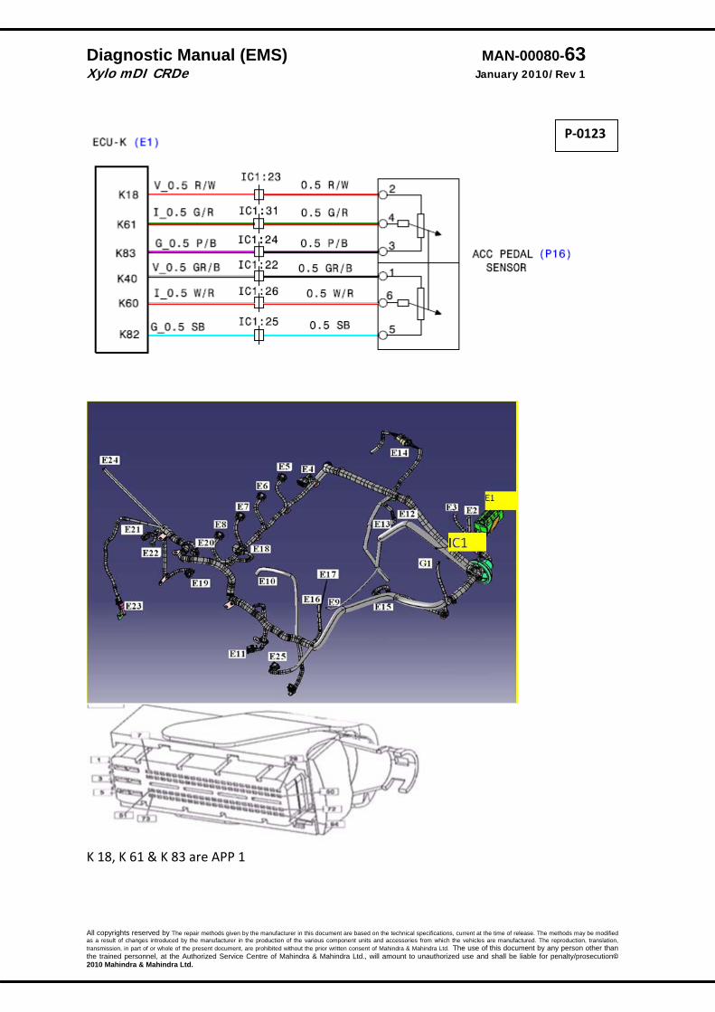
Diagnostic Manual (EMS) MAN-00080-63 Xylo mDI CRDe January 2010/Rev 1
All copyrights reserved by The repair methods given by the manufacturer in this document are based on the technical specifications, current at the time of release. The methods may be modified as a result of changes introduced by the manufacturer in the production of the various component units and accessories from which the vehicles are manufactured. The reproduction, translation, transmission, in part of or whole of the present document, are prohibited without the prior written consent of Mahindra & Mahindra Ltd. The use of this document by any person other than the trained personnel, at the Authorized Service Centre of Mahindra & Mahindra Ltd., will amount to unauthorized use and shall be liable for penalty/prosecution© 2010 Mahindra & Mahindra Ltd.
K 18, K 61 & K 83 are APP 1
P‐0123
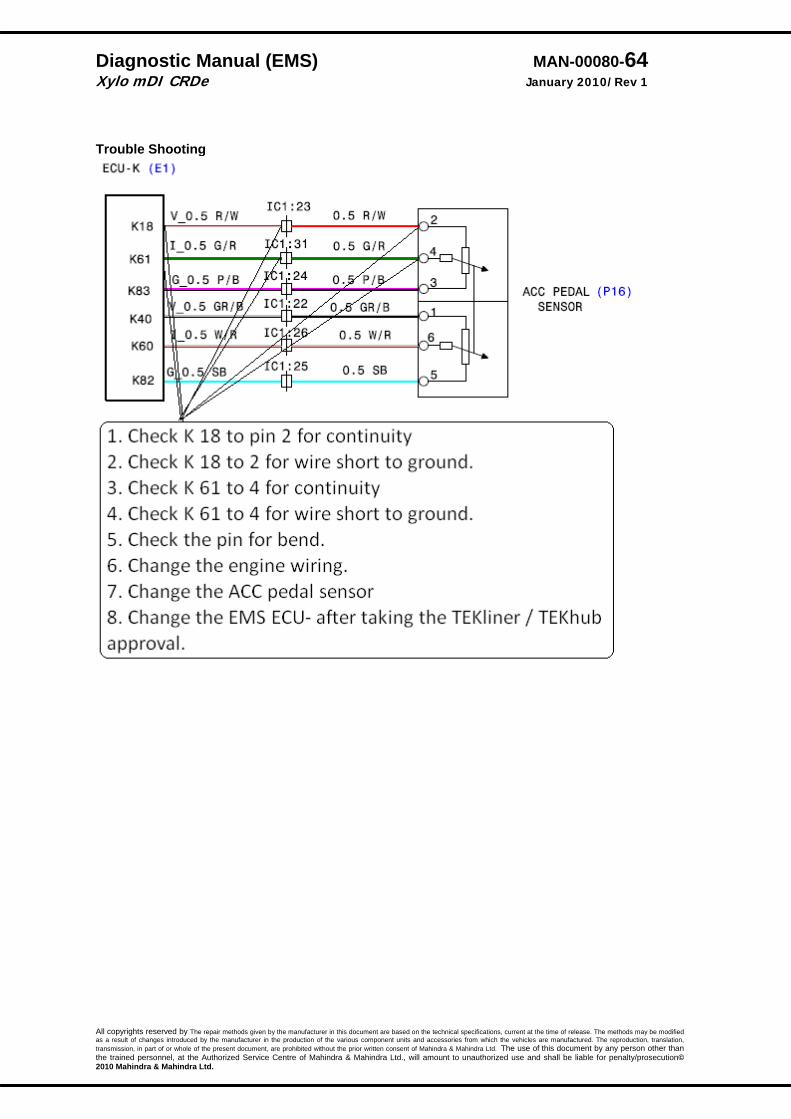
Diagnostic Manual (EMS) MAN-00080-64 Xylo mDI CRDe January 2010/Rev 1
All copyrights reserved by The repair methods given by the manufacturer in this document are based on the technical specifications, current at the time of release. The methods may be modified as a result of changes introduced by the manufacturer in the production of the various component units and accessories from which the vehicles are manufactured. The reproduction, translation, transmission, in part of or whole of the present document, are prohibited without the prior written consent of Mahindra & Mahindra Ltd. The use of this document by any person other than the trained personnel, at the Authorized Service Centre of Mahindra & Mahindra Ltd., will amount to unauthorized use and shall be liable for penalty/prosecution© 2010 Mahindra & Mahindra Ltd.
Trouble Shooting

Diagnostic Manual (EMS) MAN-00080-65 Xylo mDI CRDe January 2010/Rev 1
All copyrights reserved by The repair methods given by the manufacturer in this document are based on the technical specifications, current at the time of release. The methods may be modified as a result of changes introduced by the manufacturer in the production of the various component units and accessories from which the vehicles are manufactured. The reproduction, translation, transmission, in part of or whole of the present document, are prohibited without the prior written consent of Mahindra & Mahindra Ltd. The use of this document by any person other than the trained personnel, at the Authorized Service Centre of Mahindra & Mahindra Ltd., will amount to unauthorized use and shall be liable for penalty/prosecution© 2010 Mahindra & Mahindra Ltd.
Accelerator Pedal (APP2) Description: The Accelerator pedal module (APM) mounts in place of accelerator pedal and is connected to the ECU by wires. The APM sensor is a variable resistor (potentiometer) whose resistance changes according to the pedal position. ECU applies a reference voltage to the APM sensor and then measures the voltage that is present on the APM sensor signal circuit. The ECU uses the APM sensor signal for further calculation of fuelling & other engine operational parameters.
DTC Diagnostic item P‐0223 APP 2‐SRC high
DTC detection condition Probable cause . Proper Performance Sensor output voltage has continued to between 0 to 1.65V, varying accelerator pedal position. Malfunction; out‐of‐range
* With the changing Accelerator pedal position, the sensor output voltage has continued to be 1.65V or 0V.
Reaction:
* Fuelling is controlled‐ pedal travel is more. * The system lamp is continuously on.
Torque Limitation is active.
• Open or shorted
Accelerator pedal module circuits, loose or wrong connections.
P‐0223
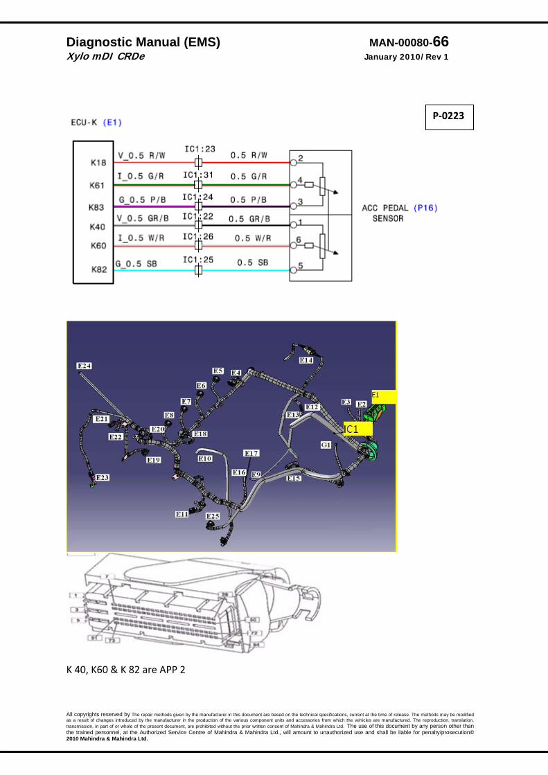
Diagnostic Manual (EMS) MAN-00080-66 Xylo mDI CRDe January 2010/Rev 1
All copyrights reserved by The repair methods given by the manufacturer in this document are based on the technical specifications, current at the time of release. The methods may be modified as a result of changes introduced by the manufacturer in the production of the various component units and accessories from which the vehicles are manufactured. The reproduction, translation, transmission, in part of or whole of the present document, are prohibited without the prior written consent of Mahindra & Mahindra Ltd. The use of this document by any person other than the trained personnel, at the Authorized Service Centre of Mahindra & Mahindra Ltd., will amount to unauthorized use and shall be liable for penalty/prosecution© 2010 Mahindra & Mahindra Ltd.
K 40, K60 & K 82 are APP 2
P‐0223
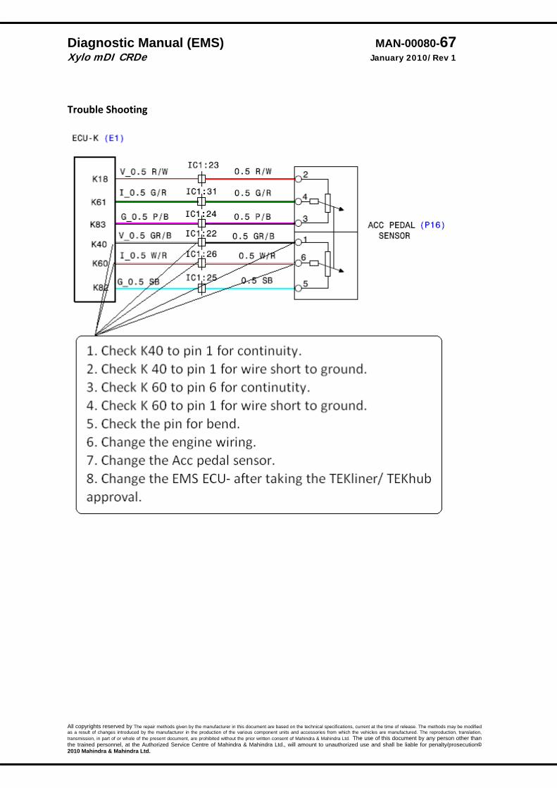
Diagnostic Manual (EMS) MAN-00080-67 Xylo mDI CRDe January 2010/Rev 1
All copyrights reserved by The repair methods given by the manufacturer in this document are based on the technical specifications, current at the time of release. The methods may be modified as a result of changes introduced by the manufacturer in the production of the various component units and accessories from which the vehicles are manufactured. The reproduction, translation, transmission, in part of or whole of the present document, are prohibited without the prior written consent of Mahindra & Mahindra Ltd. The use of this document by any person other than the trained personnel, at the Authorized Service Centre of Mahindra & Mahindra Ltd., will amount to unauthorized use and shall be liable for penalty/prosecution© 2010 Mahindra & Mahindra Ltd.
Trouble Shooting
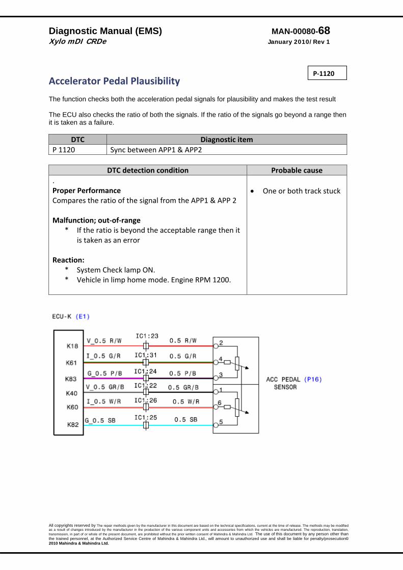
Diagnostic Manual (EMS) MAN-00080-68 Xylo mDI CRDe January 2010/Rev 1
All copyrights reserved by The repair methods given by the manufacturer in this document are based on the technical specifications, current at the time of release. The methods may be modified as a result of changes introduced by the manufacturer in the production of the various component units and accessories from which the vehicles are manufactured. The reproduction, translation, transmission, in part of or whole of the present document, are prohibited without the prior written consent of Mahindra & Mahindra Ltd. The use of this document by any person other than the trained personnel, at the Authorized Service Centre of Mahindra & Mahindra Ltd., will amount to unauthorized use and shall be liable for penalty/prosecution© 2010 Mahindra & Mahindra Ltd.
Accelerator Pedal Plausibility The function checks both the acceleration pedal signals for plausibility and makes the test result The ECU also checks the ratio of both the signals. If the ratio of the signals go beyond a range then it is taken as a failure.
DTC Diagnostic item P 1120 Sync between APP1 & APP2
DTC detection condition Probable cause . Proper Performance Compares the ratio of the signal from the APP1 & APP 2 Malfunction; out‐of‐range
* If the ratio is beyond the acceptable range then it is taken as an error
Reaction:
* System Check lamp ON. * Vehicle in limp home mode. Engine RPM 1200.
• One or both track stuck
P‐1120
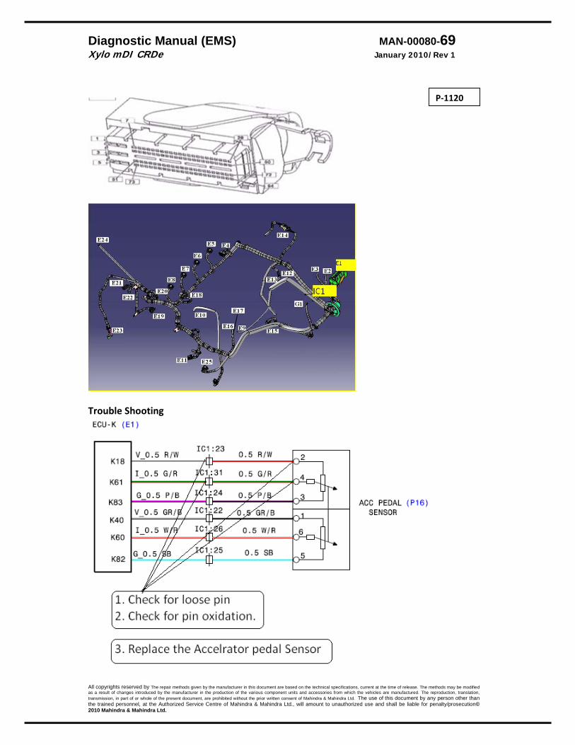
Diagnostic Manual (EMS) MAN-00080-69 Xylo mDI CRDe January 2010/Rev 1
All copyrights reserved by The repair methods given by the manufacturer in this document are based on the technical specifications, current at the time of release. The methods may be modified as a result of changes introduced by the manufacturer in the production of the various component units and accessories from which the vehicles are manufactured. The reproduction, translation, transmission, in part of or whole of the present document, are prohibited without the prior written consent of Mahindra & Mahindra Ltd. The use of this document by any person other than the trained personnel, at the Authorized Service Centre of Mahindra & Mahindra Ltd., will amount to unauthorized use and shall be liable for penalty/prosecution© 2010 Mahindra & Mahindra Ltd.
Trouble Shooting
P‐1120
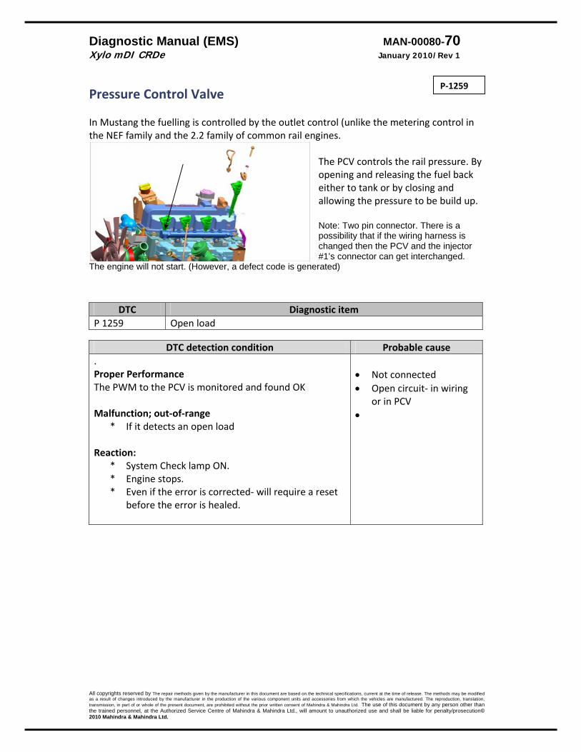
Diagnostic Manual (EMS) MAN-00080-70 Xylo mDI CRDe January 2010/Rev 1
All copyrights reserved by The repair methods given by the manufacturer in this document are based on the technical specifications, current at the time of release. The methods may be modified as a result of changes introduced by the manufacturer in the production of the various component units and accessories from which the vehicles are manufactured. The reproduction, translation, transmission, in part of or whole of the present document, are prohibited without the prior written consent of Mahindra & Mahindra Ltd. The use of this document by any person other than the trained personnel, at the Authorized Service Centre of Mahindra & Mahindra Ltd., will amount to unauthorized use and shall be liable for penalty/prosecution© 2010 Mahindra & Mahindra Ltd.
Pressure Control Valve In Mustang the fuelling is controlled by the outlet control (unlike the metering control in the NEF family and the 2.2 family of common rail engines.
The PCV controls the rail pressure. By opening and releasing the fuel back either to tank or by closing and allowing the pressure to be build up. Note: Two pin connector. There is a possibility that if the wiring harness is changed then the PCV and the injector #1’s connector can get interchanged.
The engine will not start. (However, a defect code is generated)
DTC Diagnostic itemP 1259 Open load
DTC detection condition Probable cause
. Proper Performance The PWM to the PCV is monitored and found OK Malfunction; out‐of‐range
* If it detects an open load Reaction:
* System Check lamp ON. * Engine stops. * Even if the error is corrected‐ will require a reset
before the error is healed.
• Not connected • Open circuit‐ in wiring
or in PCV •
P‐1259

Diagnostic Manual (EMS) MAN-00080-71 Xylo mDI CRDe January 2010/Rev 1
All copyrights reserved by The repair methods given by the manufacturer in this document are based on the technical specifications, current at the time of release. The methods may be modified as a result of changes introduced by the manufacturer in the production of the various component units and accessories from which the vehicles are manufactured. The reproduction, translation, transmission, in part of or whole of the present document, are prohibited without the prior written consent of Mahindra & Mahindra Ltd. The use of this document by any person other than the trained personnel, at the Authorized Service Centre of Mahindra & Mahindra Ltd., will amount to unauthorized use and shall be liable for penalty/prosecution© 2010 Mahindra & Mahindra Ltd.
P‐1259

Diagnostic Manual (EMS) MAN-00080-72 Xylo mDI CRDe January 2010/Rev 1
All copyrights reserved by The repair methods given by the manufacturer in this document are based on the technical specifications, current at the time of release. The methods may be modified as a result of changes introduced by the manufacturer in the production of the various component units and accessories from which the vehicles are manufactured. The reproduction, translation, transmission, in part of or whole of the present document, are prohibited without the prior written consent of Mahindra & Mahindra Ltd. The use of this document by any person other than the trained personnel, at the Authorized Service Centre of Mahindra & Mahindra Ltd., will amount to unauthorized use and shall be liable for penalty/prosecution© 2010 Mahindra & Mahindra Ltd.
Trouble Shooting
P‐1259
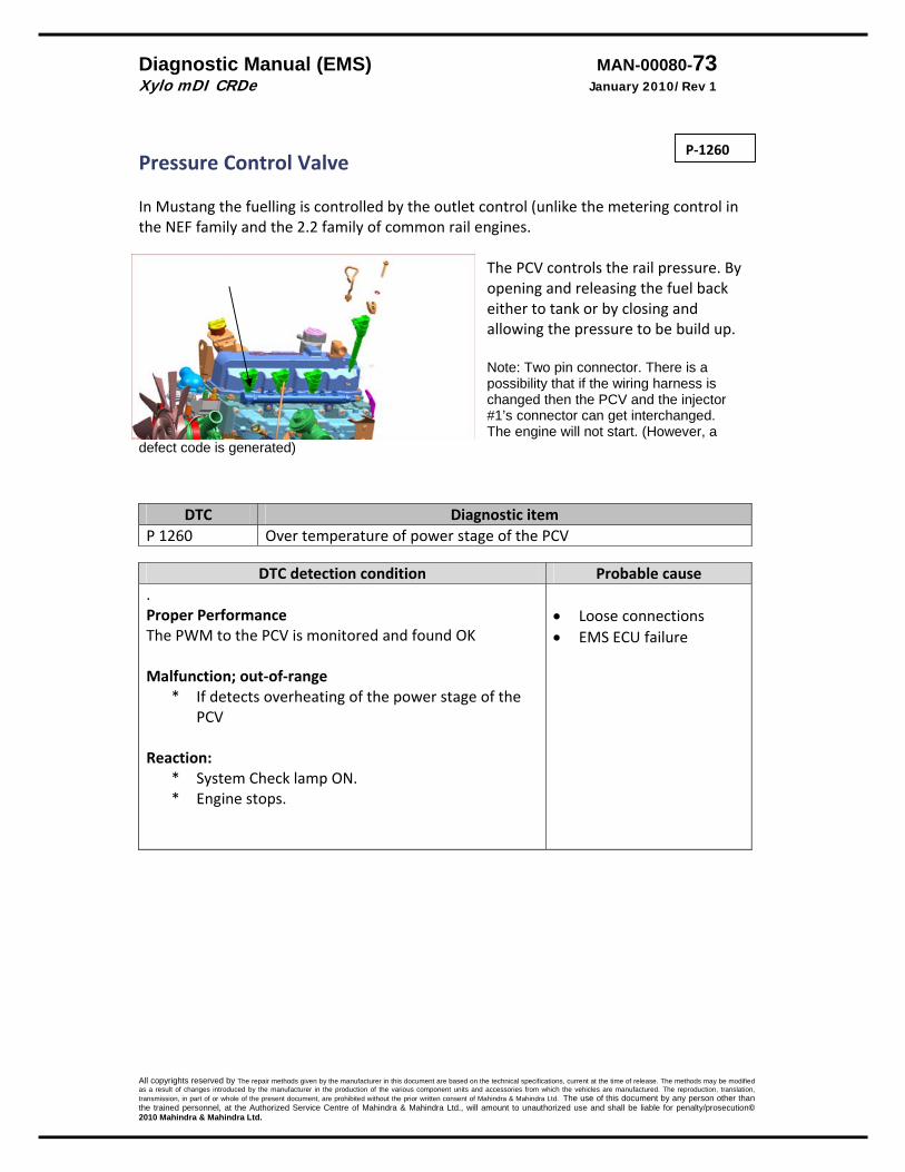
Diagnostic Manual (EMS) MAN-00080-73 Xylo mDI CRDe January 2010/Rev 1
All copyrights reserved by The repair methods given by the manufacturer in this document are based on the technical specifications, current at the time of release. The methods may be modified as a result of changes introduced by the manufacturer in the production of the various component units and accessories from which the vehicles are manufactured. The reproduction, translation, transmission, in part of or whole of the present document, are prohibited without the prior written consent of Mahindra & Mahindra Ltd. The use of this document by any person other than the trained personnel, at the Authorized Service Centre of Mahindra & Mahindra Ltd., will amount to unauthorized use and shall be liable for penalty/prosecution© 2010 Mahindra & Mahindra Ltd.
Pressure Control Valve In Mustang the fuelling is controlled by the outlet control (unlike the metering control in the NEF family and the 2.2 family of common rail engines.
The PCV controls the rail pressure. By opening and releasing the fuel back either to tank or by closing and allowing the pressure to be build up. Note: Two pin connector. There is a possibility that if the wiring harness is changed then the PCV and the injector #1’s connector can get interchanged. The engine will not start. (However, a
defect code is generated)
DTC Diagnostic itemP 1260 Over temperature of power stage of the PCV
DTC detection condition Probable cause
. Proper Performance The PWM to the PCV is monitored and found OK Malfunction; out‐of‐range
* If detects overheating of the power stage of the PCV
Reaction:
* System Check lamp ON. * Engine stops.
• Loose connections • EMS ECU failure
P‐1260
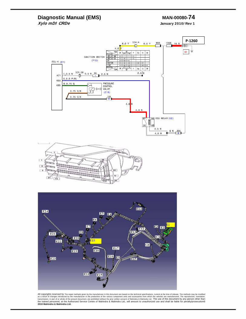
Diagnostic Manual (EMS) MAN-00080-74 Xylo mDI CRDe January 2010/Rev 1
All copyrights reserved by The repair methods given by the manufacturer in this document are based on the technical specifications, current at the time of release. The methods may be modified as a result of changes introduced by the manufacturer in the production of the various component units and accessories from which the vehicles are manufactured. The reproduction, translation, transmission, in part of or whole of the present document, are prohibited without the prior written consent of Mahindra & Mahindra Ltd. The use of this document by any person other than the trained personnel, at the Authorized Service Centre of Mahindra & Mahindra Ltd., will amount to unauthorized use and shall be liable for penalty/prosecution© 2010 Mahindra & Mahindra Ltd.
P‐1260
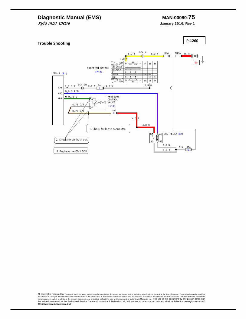
Diagnostic Manual (EMS) MAN-00080-75 Xylo mDI CRDe January 2010/Rev 1
All copyrights reserved by The repair methods given by the manufacturer in this document are based on the technical specifications, current at the time of release. The methods may be modified as a result of changes introduced by the manufacturer in the production of the various component units and accessories from which the vehicles are manufactured. The reproduction, translation, transmission, in part of or whole of the present document, are prohibited without the prior written consent of Mahindra & Mahindra Ltd. The use of this document by any person other than the trained personnel, at the Authorized Service Centre of Mahindra & Mahindra Ltd., will amount to unauthorized use and shall be liable for penalty/prosecution© 2010 Mahindra & Mahindra Ltd.
Trouble Shooting
P‐1260

Diagnostic Manual (EMS) MAN-00080-76 Xylo mDI CRDe January 2010/Rev 1
All copyrights reserved by The repair methods given by the manufacturer in this document are based on the technical specifications, current at the time of release. The methods may be modified as a result of changes introduced by the manufacturer in the production of the various component units and accessories from which the vehicles are manufactured. The reproduction, translation, transmission, in part of or whole of the present document, are prohibited without the prior written consent of Mahindra & Mahindra Ltd. The use of this document by any person other than the trained personnel, at the Authorized Service Centre of Mahindra & Mahindra Ltd., will amount to unauthorized use and shall be liable for penalty/prosecution© 2010 Mahindra & Mahindra Ltd.
Pressure Control Valve In Mustang the fuelling is controlled by the outlet control (unlike the metering control in the NEF family and the 2.2 family of common rail engines.
The PCV controls the rail pressure. By opening and releasing the fuel back either to tank or by closing and allowing the pressure to be build up. Note: Two pin connector. There is a possibility that if the wiring harness is changed then the PCV and the injector #1’s connector can get interchanged. The engine will not start. (However, a defect code is generated)
DTC Diagnostic item
P 125A Short circuit to Battery
DTC detection condition Probable cause . Proper Performance The PWM to the PCV is monitored and found OK Malfunction; out‐of‐range
* When it detects a short circuit to battery in the PCV.
Reaction:
* System Check lamp ON. * Engine stops.
• PCV • Engine w/h • EMS ECU
P‐125A

Diagnostic Manual (EMS) MAN-00080-77 Xylo mDI CRDe January 2010/Rev 1
All copyrights reserved by The repair methods given by the manufacturer in this document are based on the technical specifications, current at the time of release. The methods may be modified as a result of changes introduced by the manufacturer in the production of the various component units and accessories from which the vehicles are manufactured. The reproduction, translation, transmission, in part of or whole of the present document, are prohibited without the prior written consent of Mahindra & Mahindra Ltd. The use of this document by any person other than the trained personnel, at the Authorized Service Centre of Mahindra & Mahindra Ltd., will amount to unauthorized use and shall be liable for penalty/prosecution© 2010 Mahindra & Mahindra Ltd.
P‐125A

Diagnostic Manual (EMS) MAN-00080-78 Xylo mDI CRDe January 2010/Rev 1
All copyrights reserved by The repair methods given by the manufacturer in this document are based on the technical specifications, current at the time of release. The methods may be modified as a result of changes introduced by the manufacturer in the production of the various component units and accessories from which the vehicles are manufactured. The reproduction, translation, transmission, in part of or whole of the present document, are prohibited without the prior written consent of Mahindra & Mahindra Ltd. The use of this document by any person other than the trained personnel, at the Authorized Service Centre of Mahindra & Mahindra Ltd., will amount to unauthorized use and shall be liable for penalty/prosecution© 2010 Mahindra & Mahindra Ltd.
Trouble Shooting
P‐125A
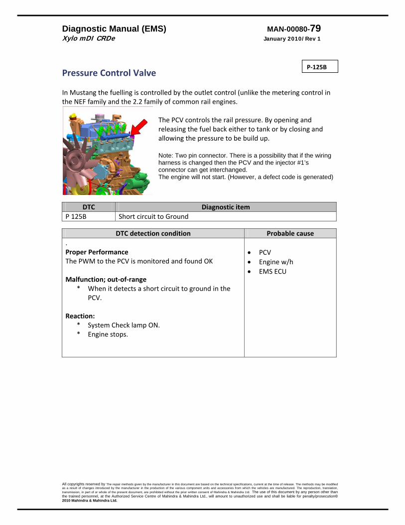
Diagnostic Manual (EMS) MAN-00080-79 Xylo mDI CRDe January 2010/Rev 1
All copyrights reserved by The repair methods given by the manufacturer in this document are based on the technical specifications, current at the time of release. The methods may be modified as a result of changes introduced by the manufacturer in the production of the various component units and accessories from which the vehicles are manufactured. The reproduction, translation, transmission, in part of or whole of the present document, are prohibited without the prior written consent of Mahindra & Mahindra Ltd. The use of this document by any person other than the trained personnel, at the Authorized Service Centre of Mahindra & Mahindra Ltd., will amount to unauthorized use and shall be liable for penalty/prosecution© 2010 Mahindra & Mahindra Ltd.
Pressure Control Valve In Mustang the fuelling is controlled by the outlet control (unlike the metering control in the NEF family and the 2.2 family of common rail engines.
The PCV controls the rail pressure. By opening and releasing the fuel back either to tank or by closing and allowing the pressure to be build up. Note: Two pin connector. There is a possibility that if the wiring harness is changed then the PCV and the injector #1’s connector can get interchanged. The engine will not start. (However, a defect code is generated)
DTC Diagnostic item
P 125B Short circuit to Ground
DTC detection condition Probable cause . Proper Performance The PWM to the PCV is monitored and found OK Malfunction; out‐of‐range
* When it detects a short circuit to ground in the PCV.
Reaction:
* System Check lamp ON. * Engine stops.
• PCV • Engine w/h • EMS ECU
P‐125B

Diagnostic Manual (EMS) MAN-00080-80 Xylo mDI CRDe January 2010/Rev 1
All copyrights reserved by The repair methods given by the manufacturer in this document are based on the technical specifications, current at the time of release. The methods may be modified as a result of changes introduced by the manufacturer in the production of the various component units and accessories from which the vehicles are manufactured. The reproduction, translation, transmission, in part of or whole of the present document, are prohibited without the prior written consent of Mahindra & Mahindra Ltd. The use of this document by any person other than the trained personnel, at the Authorized Service Centre of Mahindra & Mahindra Ltd., will amount to unauthorized use and shall be liable for penalty/prosecution© 2010 Mahindra & Mahindra Ltd.
P‐125B

Diagnostic Manual (EMS) MAN-00080-81 Xylo mDI CRDe January 2010/Rev 1
All copyrights reserved by The repair methods given by the manufacturer in this document are based on the technical specifications, current at the time of release. The methods may be modified as a result of changes introduced by the manufacturer in the production of the various component units and accessories from which the vehicles are manufactured. The reproduction, translation, transmission, in part of or whole of the present document, are prohibited without the prior written consent of Mahindra & Mahindra Ltd. The use of this document by any person other than the trained personnel, at the Authorized Service Centre of Mahindra & Mahindra Ltd., will amount to unauthorized use and shall be liable for penalty/prosecution© 2010 Mahindra & Mahindra Ltd.
Trouble Shooting
P‐125B

Diagnostic Manual (EMS) MAN-00080-82 Xylo mDI CRDe January 2010/Rev 1
All copyrights reserved by The repair methods given by the manufacturer in this document are based on the technical specifications, current at the time of release. The methods may be modified as a result of changes introduced by the manufacturer in the production of the various component units and accessories from which the vehicles are manufactured. The reproduction, translation, transmission, in part of or whole of the present document, are prohibited without the prior written consent of Mahindra & Mahindra Ltd. The use of this document by any person other than the trained personnel, at the Authorized Service Centre of Mahindra & Mahindra Ltd., will amount to unauthorized use and shall be liable for penalty/prosecution© 2010 Mahindra & Mahindra Ltd.
EKP / Pre Supply Pump
The Pre supply pump/ EPK is mounted in the fuel tank. The ECU controls the supply to the PSP. Note: The connector for this is common with the level indicator. If the EPK is switched off it will not make the noise for the first 30 seconds. In normal conditions the EPK is energized for 30 seconds. If no RPM is detected then the EPK is switched off
DTC Diagnostic item P 163F Open load
DTC detection condition Probable cause
. Proper Performance The PWM to the PCV is monitored and found OK Malfunction; out‐of‐range
* The power stage detects a open load Reaction:
* System Check lamp ON. * Engine cannot be started. * Rail pressure governing stopped. * Low pressure system is switched OFF. * Energizing time is 0
• Connectors not connected
• Oxidised pins • Pin backout
P‐163F
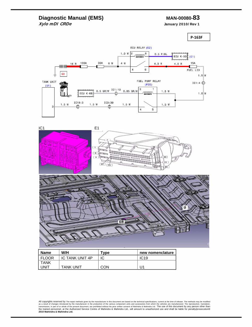
Diagnostic Manual (EMS) MAN-00080-83 Xylo mDI CRDe January 2010/Rev 1
All copyrights reserved by The repair methods given by the manufacturer in this document are based on the technical specifications, current at the time of release. The methods may be modified as a result of changes introduced by the manufacturer in the production of the various component units and accessories from which the vehicles are manufactured. The reproduction, translation, transmission, in part of or whole of the present document, are prohibited without the prior written consent of Mahindra & Mahindra Ltd. The use of this document by any person other than the trained personnel, at the Authorized Service Centre of Mahindra & Mahindra Ltd., will amount to unauthorized use and shall be liable for penalty/prosecution© 2010 Mahindra & Mahindra Ltd.
IC1 E1
Name W/H Type new nomenclatureFLOOR IC TANK UNIT 4P IC IC19 TANK UNIT TANK UNIT CON U1
P‐163F
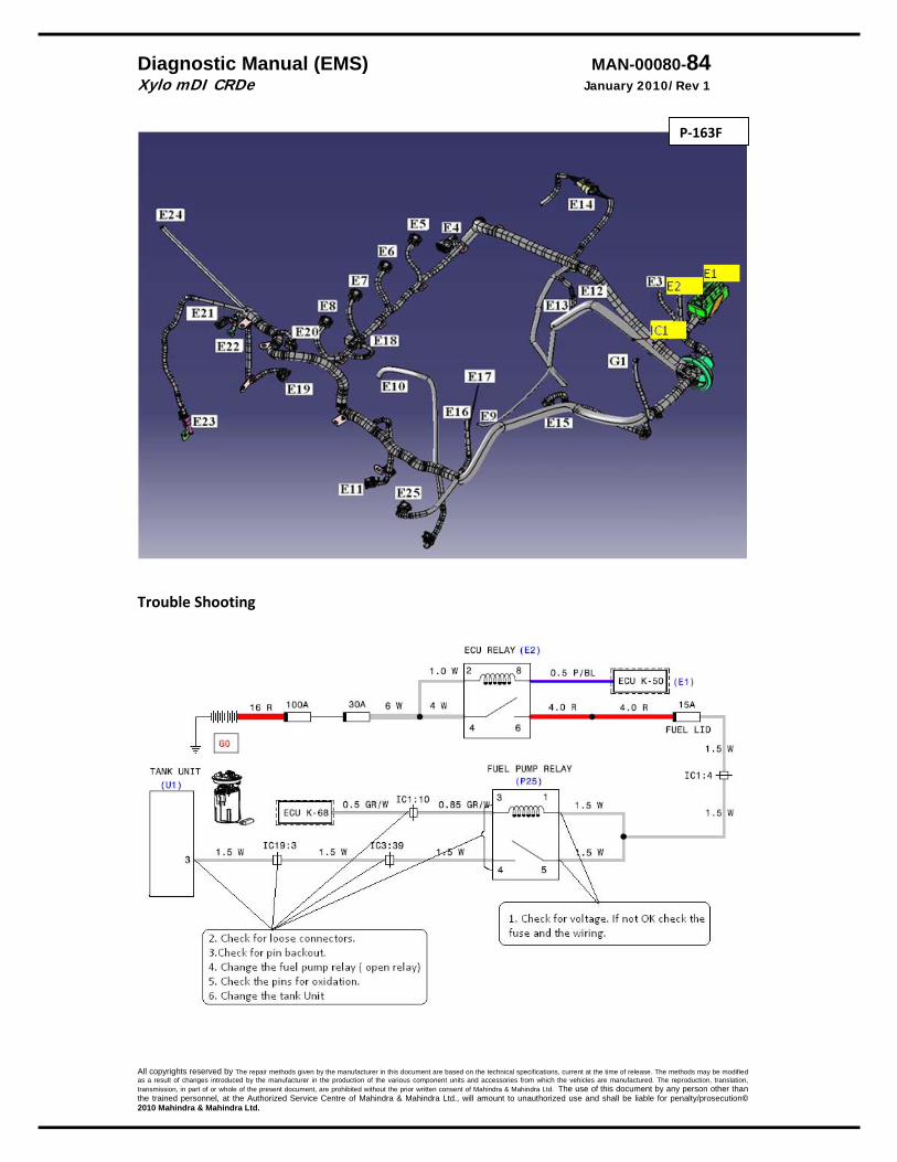
Diagnostic Manual (EMS) MAN-00080-84 Xylo mDI CRDe January 2010/Rev 1
All copyrights reserved by The repair methods given by the manufacturer in this document are based on the technical specifications, current at the time of release. The methods may be modified as a result of changes introduced by the manufacturer in the production of the various component units and accessories from which the vehicles are manufactured. The reproduction, translation, transmission, in part of or whole of the present document, are prohibited without the prior written consent of Mahindra & Mahindra Ltd. The use of this document by any person other than the trained personnel, at the Authorized Service Centre of Mahindra & Mahindra Ltd., will amount to unauthorized use and shall be liable for penalty/prosecution© 2010 Mahindra & Mahindra Ltd.
Trouble Shooting
P‐163F
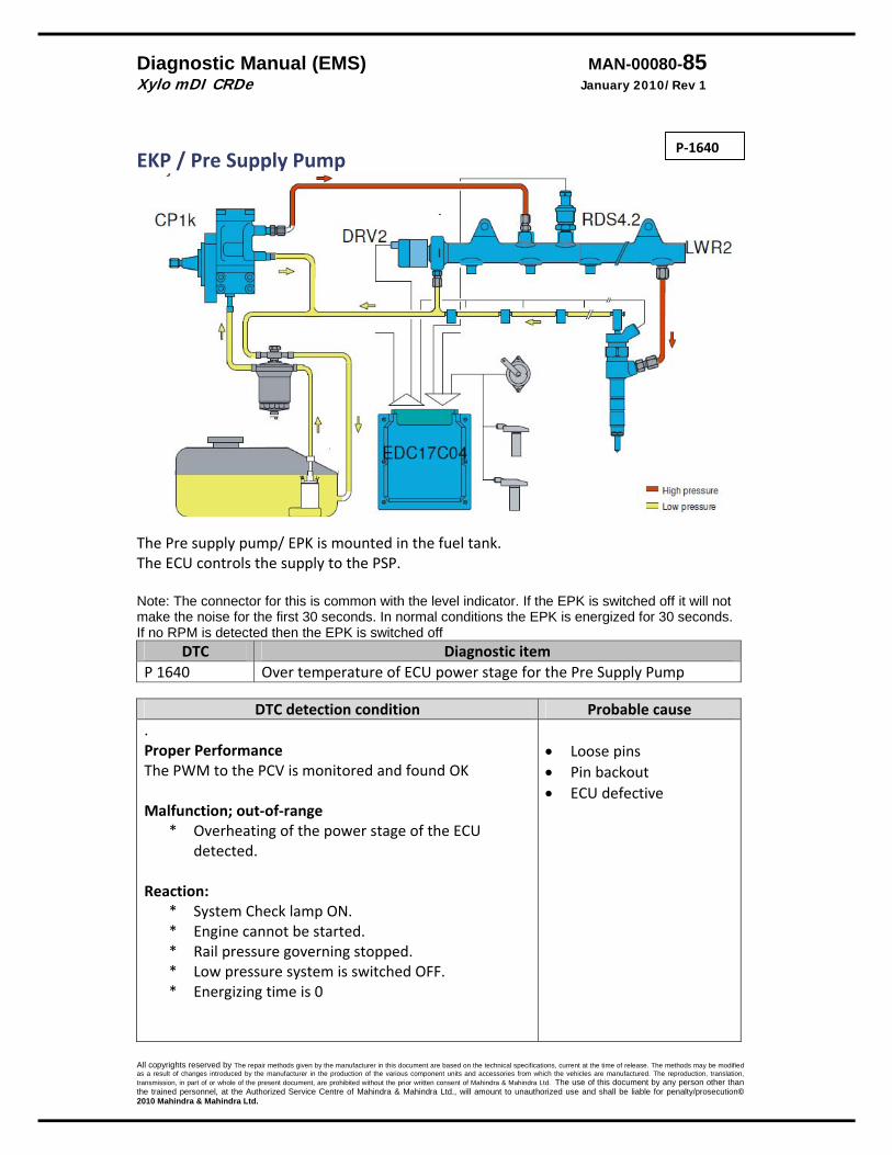
Diagnostic Manual (EMS) MAN-00080-85 Xylo mDI CRDe January 2010/Rev 1
All copyrights reserved by The repair methods given by the manufacturer in this document are based on the technical specifications, current at the time of release. The methods may be modified as a result of changes introduced by the manufacturer in the production of the various component units and accessories from which the vehicles are manufactured. The reproduction, translation, transmission, in part of or whole of the present document, are prohibited without the prior written consent of Mahindra & Mahindra Ltd. The use of this document by any person other than the trained personnel, at the Authorized Service Centre of Mahindra & Mahindra Ltd., will amount to unauthorized use and shall be liable for penalty/prosecution© 2010 Mahindra & Mahindra Ltd.
EKP / Pre Supply Pump
The Pre supply pump/ EPK is mounted in the fuel tank. The ECU controls the supply to the PSP. Note: The connector for this is common with the level indicator. If the EPK is switched off it will not make the noise for the first 30 seconds. In normal conditions the EPK is energized for 30 seconds. If no RPM is detected then the EPK is switched off
DTC Diagnostic item P 1640 Over temperature of ECU power stage for the Pre Supply Pump
DTC detection condition Probable cause
. Proper Performance The PWM to the PCV is monitored and found OK Malfunction; out‐of‐range
* Overheating of the power stage of the ECU detected.
Reaction:
* System Check lamp ON. * Engine cannot be started. * Rail pressure governing stopped. * Low pressure system is switched OFF. * Energizing time is 0
• Loose pins • Pin backout • ECU defective
P‐1640

Diagnostic Manual (EMS) MAN-00080-86 Xylo mDI CRDe January 2010/Rev 1
All copyrights reserved by The repair methods given by the manufacturer in this document are based on the technical specifications, current at the time of release. The methods may be modified as a result of changes introduced by the manufacturer in the production of the various component units and accessories from which the vehicles are manufactured. The reproduction, translation, transmission, in part of or whole of the present document, are prohibited without the prior written consent of Mahindra & Mahindra Ltd. The use of this document by any person other than the trained personnel, at the Authorized Service Centre of Mahindra & Mahindra Ltd., will amount to unauthorized use and shall be liable for penalty/prosecution© 2010 Mahindra & Mahindra Ltd.
IC1 E1
Name W/H Type new nomenclatureFLOOR IC TANK UNIT 4P IC IC19 TANK UNIT TANK UNIT CON U1
P‐1640
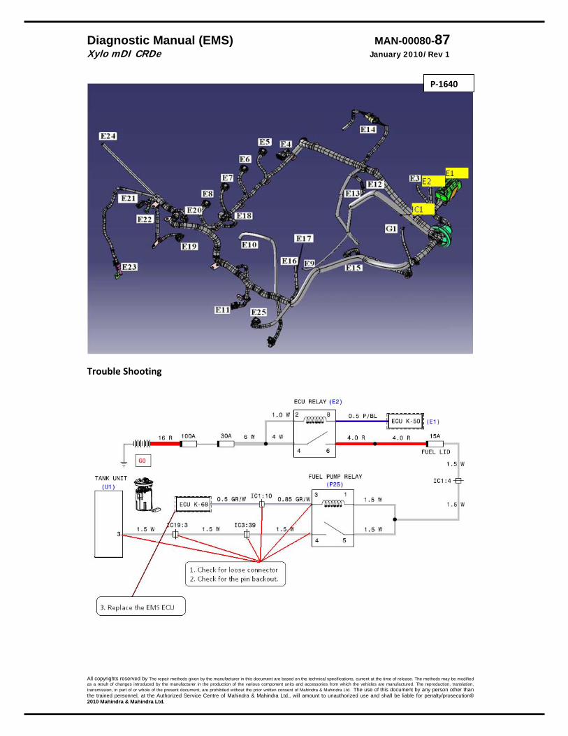
Diagnostic Manual (EMS) MAN-00080-87 Xylo mDI CRDe January 2010/Rev 1
All copyrights reserved by The repair methods given by the manufacturer in this document are based on the technical specifications, current at the time of release. The methods may be modified as a result of changes introduced by the manufacturer in the production of the various component units and accessories from which the vehicles are manufactured. The reproduction, translation, transmission, in part of or whole of the present document, are prohibited without the prior written consent of Mahindra & Mahindra Ltd. The use of this document by any person other than the trained personnel, at the Authorized Service Centre of Mahindra & Mahindra Ltd., will amount to unauthorized use and shall be liable for penalty/prosecution© 2010 Mahindra & Mahindra Ltd.
Trouble Shooting
P‐1640
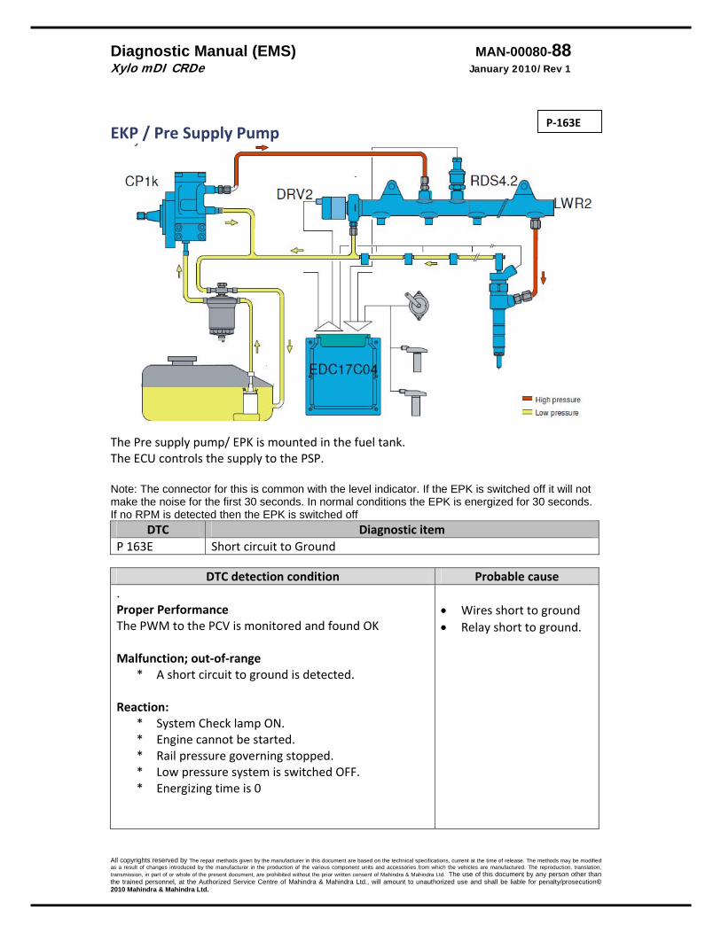
Diagnostic Manual (EMS) MAN-00080-88 Xylo mDI CRDe January 2010/Rev 1
All copyrights reserved by The repair methods given by the manufacturer in this document are based on the technical specifications, current at the time of release. The methods may be modified as a result of changes introduced by the manufacturer in the production of the various component units and accessories from which the vehicles are manufactured. The reproduction, translation, transmission, in part of or whole of the present document, are prohibited without the prior written consent of Mahindra & Mahindra Ltd. The use of this document by any person other than the trained personnel, at the Authorized Service Centre of Mahindra & Mahindra Ltd., will amount to unauthorized use and shall be liable for penalty/prosecution© 2010 Mahindra & Mahindra Ltd.
EKP / Pre Supply Pump
The Pre supply pump/ EPK is mounted in the fuel tank. The ECU controls the supply to the PSP. Note: The connector for this is common with the level indicator. If the EPK is switched off it will not make the noise for the first 30 seconds. In normal conditions the EPK is energized for 30 seconds. If no RPM is detected then the EPK is switched off
DTC Diagnostic item P 163E Short circuit to Ground
DTC detection condition Probable cause
. Proper Performance The PWM to the PCV is monitored and found OK Malfunction; out‐of‐range
* A short circuit to ground is detected. Reaction:
* System Check lamp ON. * Engine cannot be started. * Rail pressure governing stopped. * Low pressure system is switched OFF. * Energizing time is 0
• Wires short to ground • Relay short to ground.
P‐163E
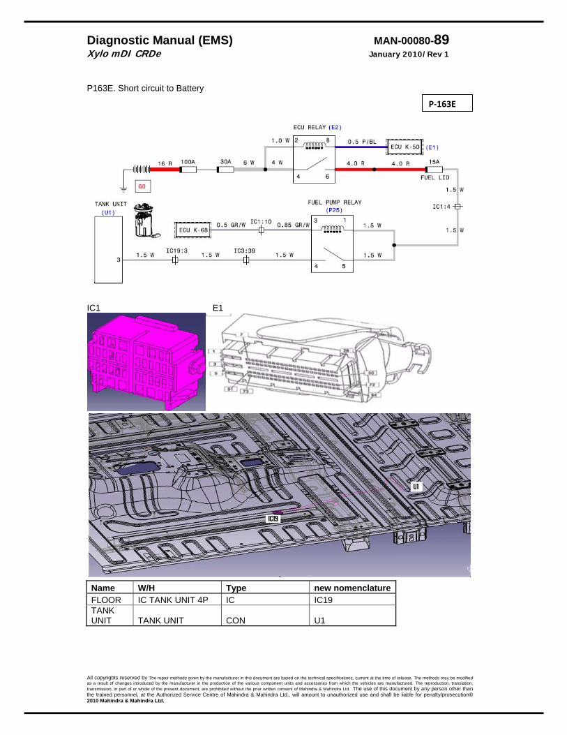
Diagnostic Manual (EMS) MAN-00080-89 Xylo mDI CRDe January 2010/Rev 1
All copyrights reserved by The repair methods given by the manufacturer in this document are based on the technical specifications, current at the time of release. The methods may be modified as a result of changes introduced by the manufacturer in the production of the various component units and accessories from which the vehicles are manufactured. The reproduction, translation, transmission, in part of or whole of the present document, are prohibited without the prior written consent of Mahindra & Mahindra Ltd. The use of this document by any person other than the trained personnel, at the Authorized Service Centre of Mahindra & Mahindra Ltd., will amount to unauthorized use and shall be liable for penalty/prosecution© 2010 Mahindra & Mahindra Ltd.
P163E. Short circuit to Battery
IC1 E1
Name W/H Type new nomenclatureFLOOR IC TANK UNIT 4P IC IC19 TANK UNIT TANK UNIT CON U1
P‐163E
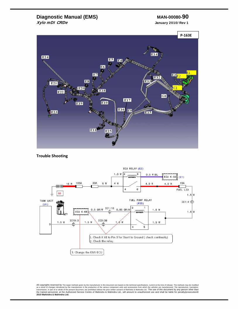
Diagnostic Manual (EMS) MAN-00080-90 Xylo mDI CRDe January 2010/Rev 1
All copyrights reserved by The repair methods given by the manufacturer in this document are based on the technical specifications, current at the time of release. The methods may be modified as a result of changes introduced by the manufacturer in the production of the various component units and accessories from which the vehicles are manufactured. The reproduction, translation, transmission, in part of or whole of the present document, are prohibited without the prior written consent of Mahindra & Mahindra Ltd. The use of this document by any person other than the trained personnel, at the Authorized Service Centre of Mahindra & Mahindra Ltd., will amount to unauthorized use and shall be liable for penalty/prosecution© 2010 Mahindra & Mahindra Ltd.
Trouble Shooting
P‐163E

Diagnostic Manual (EMS) MAN-00080-91 Xylo mDI CRDe January 2010/Rev 1
All copyrights reserved by The repair methods given by the manufacturer in this document are based on the technical specifications, current at the time of release. The methods may be modified as a result of changes introduced by the manufacturer in the production of the various component units and accessories from which the vehicles are manufactured. The reproduction, translation, transmission, in part of or whole of the present document, are prohibited without the prior written consent of Mahindra & Mahindra Ltd. The use of this document by any person other than the trained personnel, at the Authorized Service Centre of Mahindra & Mahindra Ltd., will amount to unauthorized use and shall be liable for penalty/prosecution© 2010 Mahindra & Mahindra Ltd.
EKP / Pre Supply Pump
The Pre supply pump/ EPK is mounted in the fuel tank. The ECU controls the supply to the PSP. Note: The connector for this is common with the level indicator. If the EPK is switched off it will not make the noise for the first 30 seconds. In normal conditions the EPK is energized for 30 seconds. If no RPM is detected then the EPK is switched off
DTC Diagnostic item P 163D Short circuit to Battery
DTC detection condition Probable cause
. Proper Performance The PWM to the PCV is monitored and found OK Malfunction; out‐of‐range
* A short circuit to ground is detected. Reaction:
* System Check lamp ON. * Engine cannot be started. * Rail pressure governing stopped. * Low pressure system is switched OFF. * Energizing time is 0
• Wires short to Battery • Relay short to Battery. • EMS ECU short to Batt.
P163E. Short circuit to Battery
P‐163D
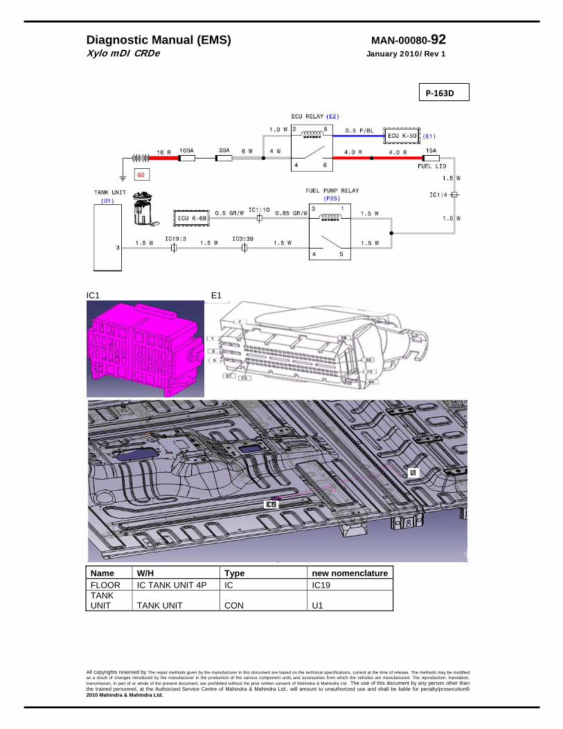
Diagnostic Manual (EMS) MAN-00080-92 Xylo mDI CRDe January 2010/Rev 1
All copyrights reserved by The repair methods given by the manufacturer in this document are based on the technical specifications, current at the time of release. The methods may be modified as a result of changes introduced by the manufacturer in the production of the various component units and accessories from which the vehicles are manufactured. The reproduction, translation, transmission, in part of or whole of the present document, are prohibited without the prior written consent of Mahindra & Mahindra Ltd. The use of this document by any person other than the trained personnel, at the Authorized Service Centre of Mahindra & Mahindra Ltd., will amount to unauthorized use and shall be liable for penalty/prosecution© 2010 Mahindra & Mahindra Ltd.
IC1 E1
Name W/H Type new nomenclatureFLOOR IC TANK UNIT 4P IC IC19 TANK UNIT TANK UNIT CON U1
P‐163D

Diagnostic Manual (EMS) MAN-00080-93 Xylo mDI CRDe January 2010/Rev 1
All copyrights reserved by The repair methods given by the manufacturer in this document are based on the technical specifications, current at the time of release. The methods may be modified as a result of changes introduced by the manufacturer in the production of the various component units and accessories from which the vehicles are manufactured. The reproduction, translation, transmission, in part of or whole of the present document, are prohibited without the prior written consent of Mahindra & Mahindra Ltd. The use of this document by any person other than the trained personnel, at the Authorized Service Centre of Mahindra & Mahindra Ltd., will amount to unauthorized use and shall be liable for penalty/prosecution© 2010 Mahindra & Mahindra Ltd.
Trouble Shooting
P‐163D
Diagnostic Manual (EMS) MAN-00080-94 Xylo mDI CRDe January 2010/Rev 1
All copyrights reserved by The repair methods given by the manufacturer in this document are based on the technical specifications, current at the time of release. The methods may be modified as a result of changes introduced by the manufacturer in the production of the various component units and accessories from which the vehicles are manufactured. The reproduction, translation, transmission, in part of or whole of the present document, are prohibited without the prior written consent of Mahindra & Mahindra Ltd. The use of this document by any person other than the trained personnel, at the Authorized Service Centre of Mahindra & Mahindra Ltd., will amount to unauthorized use and shall be liable for penalty/prosecution© 2010 Mahindra & Mahindra Ltd.
Injector The injectors are solenoid controlled. EMS ECU does the control of the solenoids.
DTC Diagnostic item P 0202 Injector Bank Failure
DTC detection condition Probable cause
. Proper Performance The injector bank is checked during initialization and while running and found OK. Malfunction; out‐of‐range
* Short circuit in injection bank Reaction:
* Injection bank will not work ( since there is only 1 injection bank in this case‐ all the 4 injectors will not work)
• Wiring short. • Wiring short + EMS ECU
failure
P‐0202

Diagnostic Manual (EMS) MAN-00080-95 Xylo mDI CRDe January 2010/Rev 1
All copyrights reserved by The repair methods given by the manufacturer in this document are based on the technical specifications, current at the time of release. The methods may be modified as a result of changes introduced by the manufacturer in the production of the various component units and accessories from which the vehicles are manufactured. The reproduction, translation, transmission, in part of or whole of the present document, are prohibited without the prior written consent of Mahindra & Mahindra Ltd. The use of this document by any person other than the trained personnel, at the Authorized Service Centre of Mahindra & Mahindra Ltd., will amount to unauthorized use and shall be liable for penalty/prosecution© 2010 Mahindra & Mahindra Ltd.
Note: Injector No are counted from fan
P‐0202

Diagnostic Manual (EMS) MAN-00080-96 Xylo mDI CRDe January 2010/Rev 1
All copyrights reserved by The repair methods given by the manufacturer in this document are based on the technical specifications, current at the time of release. The methods may be modified as a result of changes introduced by the manufacturer in the production of the various component units and accessories from which the vehicles are manufactured. The reproduction, translation, transmission, in part of or whole of the present document, are prohibited without the prior written consent of Mahindra & Mahindra Ltd. The use of this document by any person other than the trained personnel, at the Authorized Service Centre of Mahindra & Mahindra Ltd., will amount to unauthorized use and shall be liable for penalty/prosecution© 2010 Mahindra & Mahindra Ltd.
Trouble Shooting
Note: Injector No are counted from fan
P‐0202
Diagnostic Manual (EMS) MAN-00080-97 Xylo mDI CRDe January 2010/Rev 1
All copyrights reserved by The repair methods given by the manufacturer in this document are based on the technical specifications, current at the time of release. The methods may be modified as a result of changes introduced by the manufacturer in the production of the various component units and accessories from which the vehicles are manufactured. The reproduction, translation, transmission, in part of or whole of the present document, are prohibited without the prior written consent of Mahindra & Mahindra Ltd. The use of this document by any person other than the trained personnel, at the Authorized Service Centre of Mahindra & Mahindra Ltd., will amount to unauthorized use and shall be liable for penalty/prosecution© 2010 Mahindra & Mahindra Ltd.
Injector The injectors are solenoid controlled. EMS ECU does the control of the solenoids.
DTC Diagnostic itemP 1210 Chip error in the CY33x power stage component
DTC detection condition Probable cause
. Proper Performance The PWM to the injector is monitored and found OK Malfunction; out‐of‐range
* Short circuit in injection bank Reaction:
* System check lamp will glow. * Engine will not start
• EMS ECU failure.
Trouble Shooting Replace the EMS ECU‐ after taking the approval of the TEKliner/TEKhub.
P‐1210
Diagnostic Manual (EMS) MAN-00080-98 Xylo mDI CRDe January 2010/Rev 1
All copyrights reserved by The repair methods given by the manufacturer in this document are based on the technical specifications, current at the time of release. The methods may be modified as a result of changes introduced by the manufacturer in the production of the various component units and accessories from which the vehicles are manufactured. The reproduction, translation, transmission, in part of or whole of the present document, are prohibited without the prior written consent of Mahindra & Mahindra Ltd. The use of this document by any person other than the trained personnel, at the Authorized Service Centre of Mahindra & Mahindra Ltd., will amount to unauthorized use and shall be liable for penalty/prosecution© 2010 Mahindra & Mahindra Ltd.
Injector The injectors are solenoid controlled. EMS ECU does the control of the solenoids.
DTC Diagnostic item P 126C Injector valve, 1st Cylinder, Open Load P 127C Injector valve, 2nd Cylinder, Open Load P128C Injector valve, 3rd Cylinder, Open Load P129C Injector valve, 4th Cylinder, Open Load
DTC detection condition Probable cause
. Proper Performance The PWM to the injectors is monitored and found OK Malfunction; out‐of‐range
* When it detects open load of the injector ( interruption of the electrical connection)
Reaction:
* System check lamp will glow. * Engine will not start
• Connectors open • Open ciruit • Pin back out
P126C P127C P128C P129C
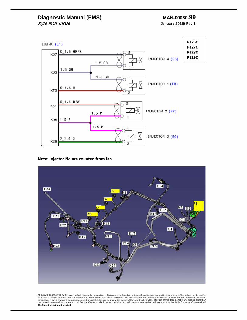
Diagnostic Manual (EMS) MAN-00080-99 Xylo mDI CRDe January 2010/Rev 1
All copyrights reserved by The repair methods given by the manufacturer in this document are based on the technical specifications, current at the time of release. The methods may be modified as a result of changes introduced by the manufacturer in the production of the various component units and accessories from which the vehicles are manufactured. The reproduction, translation, transmission, in part of or whole of the present document, are prohibited without the prior written consent of Mahindra & Mahindra Ltd. The use of this document by any person other than the trained personnel, at the Authorized Service Centre of Mahindra & Mahindra Ltd., will amount to unauthorized use and shall be liable for penalty/prosecution© 2010 Mahindra & Mahindra Ltd.
Note: Injector No are counted from fan
P126C P127C P128C P129C

Diagnostic Manual (EMS) MAN-00080-100 Xylo mDI CRDe January 2010/Rev 1
All copyrights reserved by The repair methods given by the manufacturer in this document are based on the technical specifications, current at the time of release. The methods may be modified as a result of changes introduced by the manufacturer in the production of the various component units and accessories from which the vehicles are manufactured. The reproduction, translation, transmission, in part of or whole of the present document, are prohibited without the prior written consent of Mahindra & Mahindra Ltd. The use of this document by any person other than the trained personnel, at the Authorized Service Centre of Mahindra & Mahindra Ltd., will amount to unauthorized use and shall be liable for penalty/prosecution© 2010 Mahindra & Mahindra Ltd.
Trouble Shooting
Note: Injector No are counted from fan
P126C P127C P128C P129C
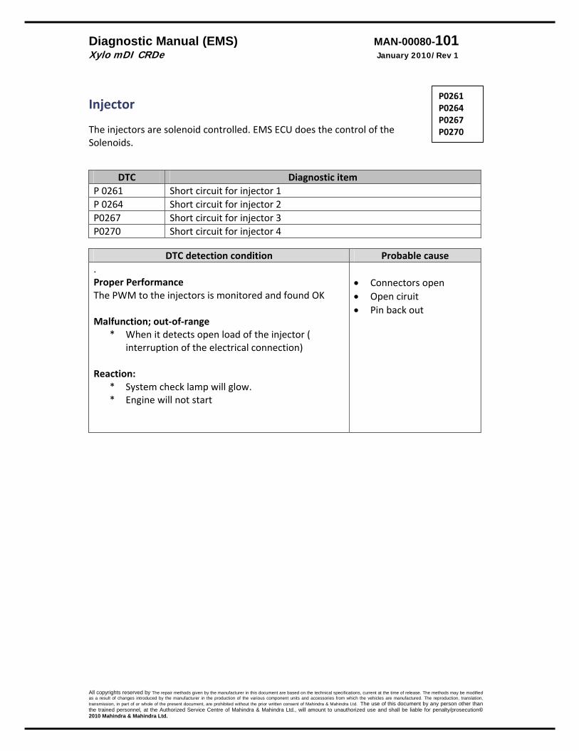
Diagnostic Manual (EMS) MAN-00080-101 Xylo mDI CRDe January 2010/Rev 1
All copyrights reserved by The repair methods given by the manufacturer in this document are based on the technical specifications, current at the time of release. The methods may be modified as a result of changes introduced by the manufacturer in the production of the various component units and accessories from which the vehicles are manufactured. The reproduction, translation, transmission, in part of or whole of the present document, are prohibited without the prior written consent of Mahindra & Mahindra Ltd. The use of this document by any person other than the trained personnel, at the Authorized Service Centre of Mahindra & Mahindra Ltd., will amount to unauthorized use and shall be liable for penalty/prosecution© 2010 Mahindra & Mahindra Ltd.
Injector The injectors are solenoid controlled. EMS ECU does the control of the Solenoids.
DTC Diagnostic item P 0261 Short circuit for injector 1 P 0264 Short circuit for injector 2P0267 Short circuit for injector 3P0270 Short circuit for injector 4
DTC detection condition Probable cause
. Proper Performance The PWM to the injectors is monitored and found OK Malfunction; out‐of‐range
* When it detects open load of the injector ( interruption of the electrical connection)
Reaction:
* System check lamp will glow. * Engine will not start
• Connectors open • Open ciruit • Pin back out
P0261 P0264 P0267 P0270

Diagnostic Manual (EMS) MAN-00080-102 Xylo mDI CRDe January 2010/Rev 1
All copyrights reserved by The repair methods given by the manufacturer in this document are based on the technical specifications, current at the time of release. The methods may be modified as a result of changes introduced by the manufacturer in the production of the various component units and accessories from which the vehicles are manufactured. The reproduction, translation, transmission, in part of or whole of the present document, are prohibited without the prior written consent of Mahindra & Mahindra Ltd. The use of this document by any person other than the trained personnel, at the Authorized Service Centre of Mahindra & Mahindra Ltd., will amount to unauthorized use and shall be liable for penalty/prosecution© 2010 Mahindra & Mahindra Ltd.
Note: Injector No are counted from fan
P0261 P0264 P0267 P0270
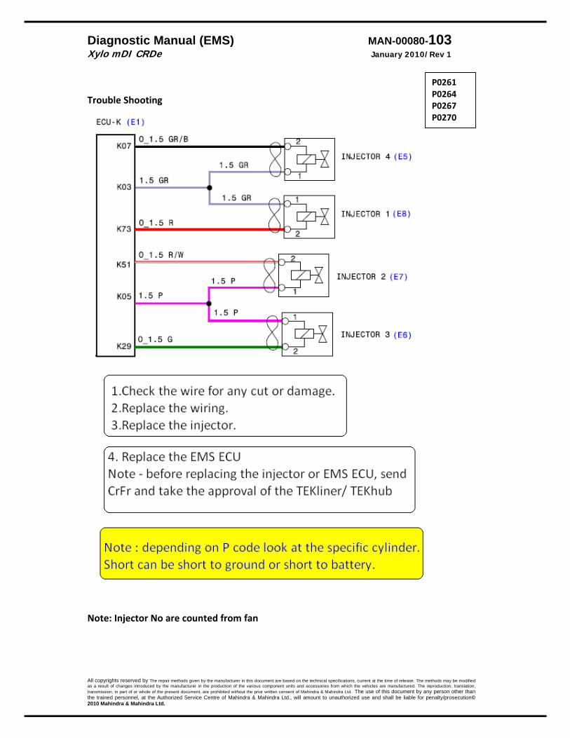
Diagnostic Manual (EMS) MAN-00080-103 Xylo mDI CRDe January 2010/Rev 1
All copyrights reserved by The repair methods given by the manufacturer in this document are based on the technical specifications, current at the time of release. The methods may be modified as a result of changes introduced by the manufacturer in the production of the various component units and accessories from which the vehicles are manufactured. The reproduction, translation, transmission, in part of or whole of the present document, are prohibited without the prior written consent of Mahindra & Mahindra Ltd. The use of this document by any person other than the trained personnel, at the Authorized Service Centre of Mahindra & Mahindra Ltd., will amount to unauthorized use and shall be liable for penalty/prosecution© 2010 Mahindra & Mahindra Ltd.
Trouble Shooting
Note: Injector No are counted from fan
P0261 P0264 P0267 P0270
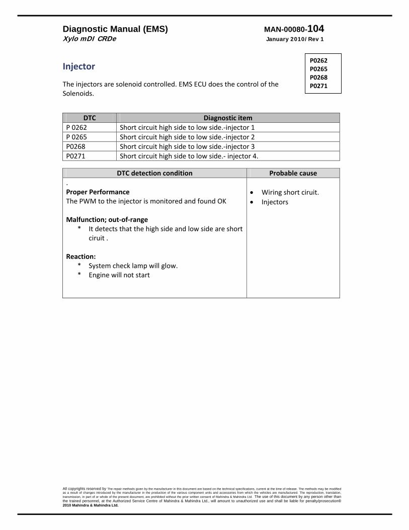
Diagnostic Manual (EMS) MAN-00080-104 Xylo mDI CRDe January 2010/Rev 1
All copyrights reserved by The repair methods given by the manufacturer in this document are based on the technical specifications, current at the time of release. The methods may be modified as a result of changes introduced by the manufacturer in the production of the various component units and accessories from which the vehicles are manufactured. The reproduction, translation, transmission, in part of or whole of the present document, are prohibited without the prior written consent of Mahindra & Mahindra Ltd. The use of this document by any person other than the trained personnel, at the Authorized Service Centre of Mahindra & Mahindra Ltd., will amount to unauthorized use and shall be liable for penalty/prosecution© 2010 Mahindra & Mahindra Ltd.
Injector The injectors are solenoid controlled. EMS ECU does the control of the Solenoids.
DTC Diagnostic itemP 0262 Short circuit high side to low side.‐injector 1P 0265 Short circuit high side to low side.‐injector 2P0268 Short circuit high side to low side.‐injector 3P0271 Short circuit high side to low side.‐ injector 4.
DTC detection condition Probable cause
. Proper Performance The PWM to the injector is monitored and found OK Malfunction; out‐of‐range
* It detects that the high side and low side are short ciruit .
Reaction:
* System check lamp will glow. * Engine will not start
• Wiring short ciruit. • Injectors
P0262 P0265 P0268 P0271
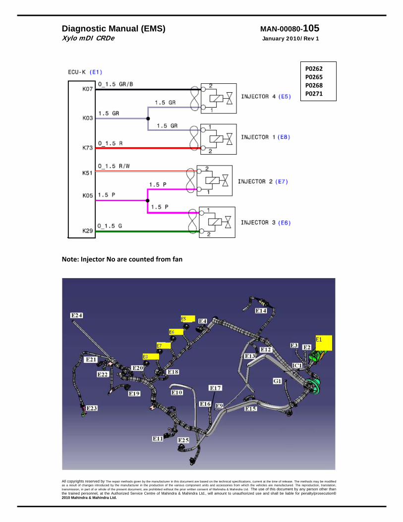
Diagnostic Manual (EMS) MAN-00080-105 Xylo mDI CRDe January 2010/Rev 1
All copyrights reserved by The repair methods given by the manufacturer in this document are based on the technical specifications, current at the time of release. The methods may be modified as a result of changes introduced by the manufacturer in the production of the various component units and accessories from which the vehicles are manufactured. The reproduction, translation, transmission, in part of or whole of the present document, are prohibited without the prior written consent of Mahindra & Mahindra Ltd. The use of this document by any person other than the trained personnel, at the Authorized Service Centre of Mahindra & Mahindra Ltd., will amount to unauthorized use and shall be liable for penalty/prosecution© 2010 Mahindra & Mahindra Ltd.
Note: Injector No are counted from fan
P0262 P0265 P0268 P0271
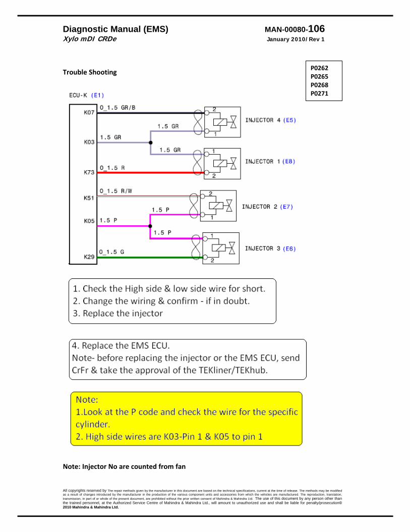
Diagnostic Manual (EMS) MAN-00080-106 Xylo mDI CRDe January 2010/Rev 1
All copyrights reserved by The repair methods given by the manufacturer in this document are based on the technical specifications, current at the time of release. The methods may be modified as a result of changes introduced by the manufacturer in the production of the various component units and accessories from which the vehicles are manufactured. The reproduction, translation, transmission, in part of or whole of the present document, are prohibited without the prior written consent of Mahindra & Mahindra Ltd. The use of this document by any person other than the trained personnel, at the Authorized Service Centre of Mahindra & Mahindra Ltd., will amount to unauthorized use and shall be liable for penalty/prosecution© 2010 Mahindra & Mahindra Ltd.
Trouble Shooting
Note: Injector No are counted from fan
P0262 P0265 P0268 P0271

Diagnostic Manual (EMS) MAN-00080-107 Xylo mDI CRDe January 2010/Rev 1
All copyrights reserved by The repair methods given by the manufacturer in this document are based on the technical specifications, current at the time of release. The methods may be modified as a result of changes introduced by the manufacturer in the production of the various component units and accessories from which the vehicles are manufactured. The reproduction, translation, transmission, in part of or whole of the present document, are prohibited without the prior written consent of Mahindra & Mahindra Ltd. The use of this document by any person other than the trained personnel, at the Authorized Service Centre of Mahindra & Mahindra Ltd., will amount to unauthorized use and shall be liable for penalty/prosecution© 2010 Mahindra & Mahindra Ltd.
EGR Description A pulse‐width‐modulated signal is output for the Exhaust Gas Recirculation actuator control. Converting the air control output into duty cycle carries this out. The possible defects are short circuit to battery, ground & no load.
DTC Diagnostic item P‐0403 Open load
DTC detection condition Probable cause
Background * The ECU checks current flows in the EGR solenoid
drive circuit when the solenoid is ON and OFF. Range of check, set conditions.
* When the EGR solenoid is turned OFF, no surge voltage is detected.
Normal operation When engine is running per the EGR mapping. • System lamp off after 2 sec. Malfunction • EGR valve will remain open in case of short circuit to
ground fault & remain closed for other fault conditions. Reaction • System lamp will blink. • EGR switched off
* Connector not connected.
* Fuse failure * Wire open * Pin backout * Pins oxidation
.
P0403
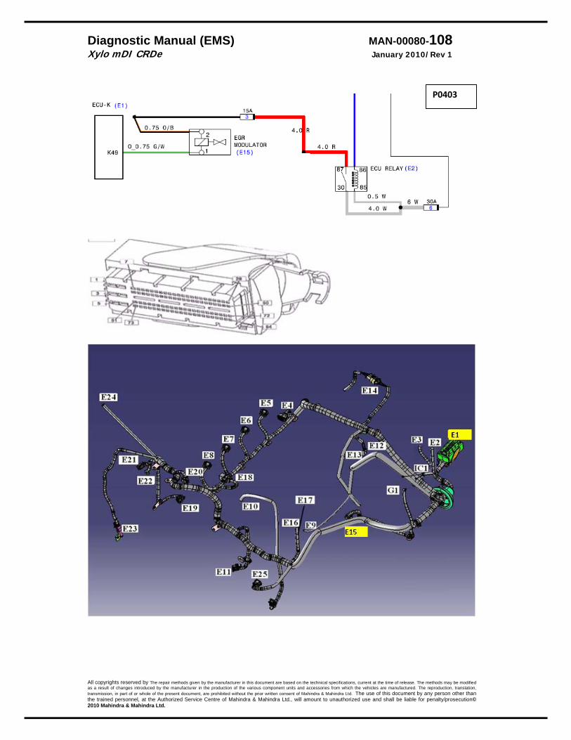
Diagnostic Manual (EMS) MAN-00080-108 Xylo mDI CRDe January 2010/Rev 1
All copyrights reserved by The repair methods given by the manufacturer in this document are based on the technical specifications, current at the time of release. The methods may be modified as a result of changes introduced by the manufacturer in the production of the various component units and accessories from which the vehicles are manufactured. The reproduction, translation, transmission, in part of or whole of the present document, are prohibited without the prior written consent of Mahindra & Mahindra Ltd. The use of this document by any person other than the trained personnel, at the Authorized Service Centre of Mahindra & Mahindra Ltd., will amount to unauthorized use and shall be liable for penalty/prosecution© 2010 Mahindra & Mahindra Ltd.
P0403
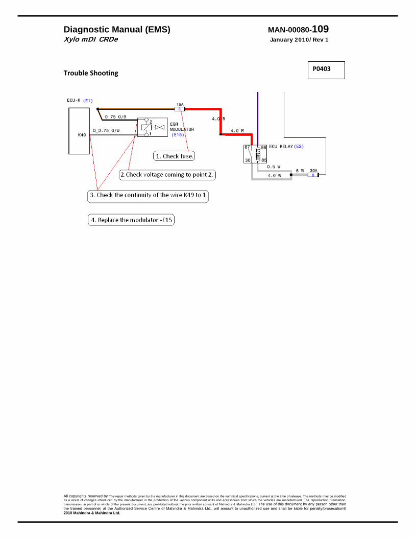
Diagnostic Manual (EMS) MAN-00080-109 Xylo mDI CRDe January 2010/Rev 1
All copyrights reserved by The repair methods given by the manufacturer in this document are based on the technical specifications, current at the time of release. The methods may be modified as a result of changes introduced by the manufacturer in the production of the various component units and accessories from which the vehicles are manufactured. The reproduction, translation, transmission, in part of or whole of the present document, are prohibited without the prior written consent of Mahindra & Mahindra Ltd. The use of this document by any person other than the trained personnel, at the Authorized Service Centre of Mahindra & Mahindra Ltd., will amount to unauthorized use and shall be liable for penalty/prosecution© 2010 Mahindra & Mahindra Ltd.
Trouble Shooting
P0403
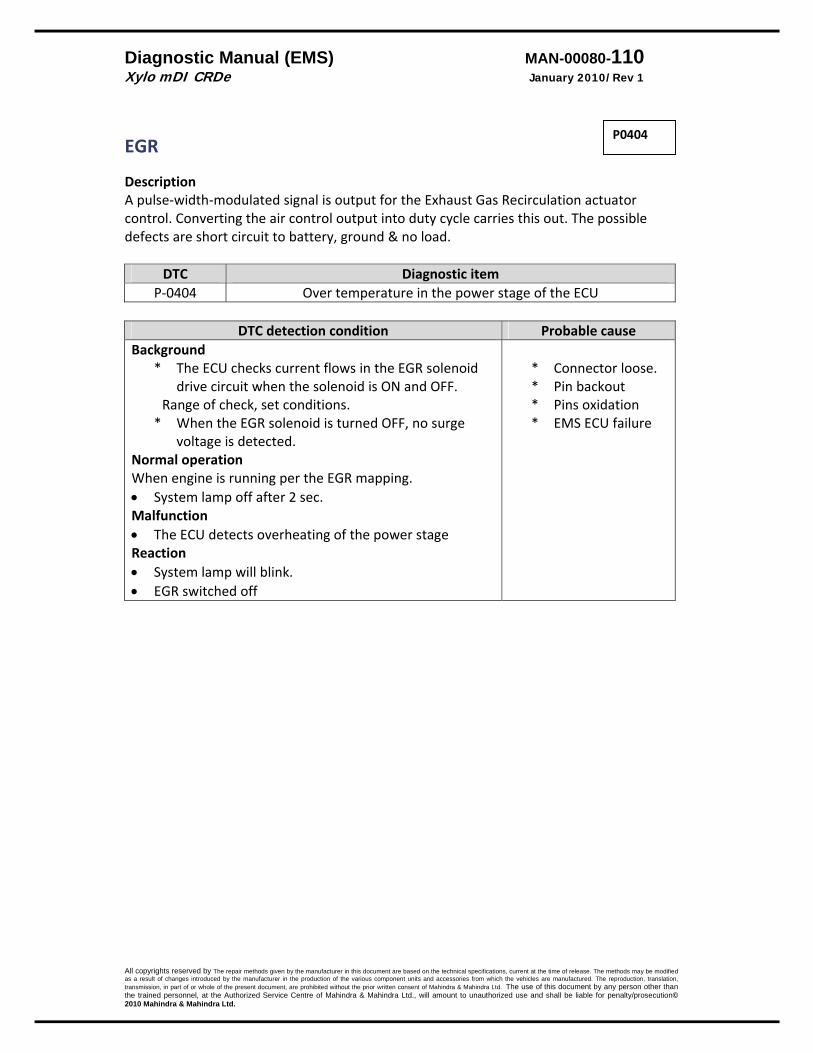
Diagnostic Manual (EMS) MAN-00080-110 Xylo mDI CRDe January 2010/Rev 1
All copyrights reserved by The repair methods given by the manufacturer in this document are based on the technical specifications, current at the time of release. The methods may be modified as a result of changes introduced by the manufacturer in the production of the various component units and accessories from which the vehicles are manufactured. The reproduction, translation, transmission, in part of or whole of the present document, are prohibited without the prior written consent of Mahindra & Mahindra Ltd. The use of this document by any person other than the trained personnel, at the Authorized Service Centre of Mahindra & Mahindra Ltd., will amount to unauthorized use and shall be liable for penalty/prosecution© 2010 Mahindra & Mahindra Ltd.
EGR Description A pulse‐width‐modulated signal is output for the Exhaust Gas Recirculation actuator control. Converting the air control output into duty cycle carries this out. The possible defects are short circuit to battery, ground & no load.
DTC Diagnostic item P‐0404 Over temperature in the power stage of the ECU
DTC detection condition Probable cause
Background * The ECU checks current flows in the EGR solenoid
drive circuit when the solenoid is ON and OFF. Range of check, set conditions.
* When the EGR solenoid is turned OFF, no surge voltage is detected.
Normal operation When engine is running per the EGR mapping. • System lamp off after 2 sec. Malfunction • The ECU detects overheating of the power stage Reaction • System lamp will blink. • EGR switched off
* Connector loose. * Pin backout * Pins oxidation * EMS ECU failure
P0404
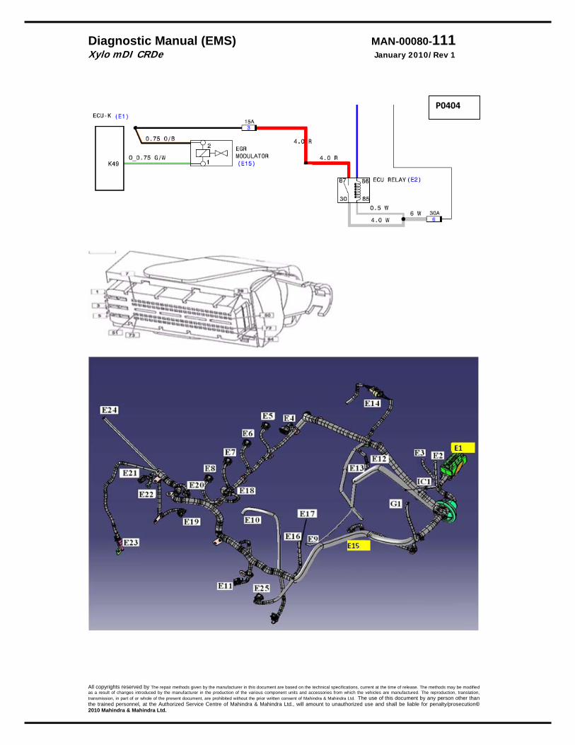
Diagnostic Manual (EMS) MAN-00080-111 Xylo mDI CRDe January 2010/Rev 1
All copyrights reserved by The repair methods given by the manufacturer in this document are based on the technical specifications, current at the time of release. The methods may be modified as a result of changes introduced by the manufacturer in the production of the various component units and accessories from which the vehicles are manufactured. The reproduction, translation, transmission, in part of or whole of the present document, are prohibited without the prior written consent of Mahindra & Mahindra Ltd. The use of this document by any person other than the trained personnel, at the Authorized Service Centre of Mahindra & Mahindra Ltd., will amount to unauthorized use and shall be liable for penalty/prosecution© 2010 Mahindra & Mahindra Ltd.
P0404
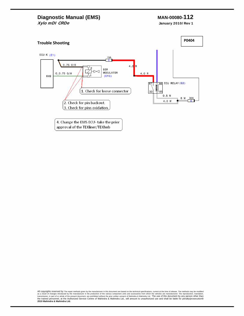
Diagnostic Manual (EMS) MAN-00080-112 Xylo mDI CRDe January 2010/Rev 1
All copyrights reserved by The repair methods given by the manufacturer in this document are based on the technical specifications, current at the time of release. The methods may be modified as a result of changes introduced by the manufacturer in the production of the various component units and accessories from which the vehicles are manufactured. The reproduction, translation, transmission, in part of or whole of the present document, are prohibited without the prior written consent of Mahindra & Mahindra Ltd. The use of this document by any person other than the trained personnel, at the Authorized Service Centre of Mahindra & Mahindra Ltd., will amount to unauthorized use and shall be liable for penalty/prosecution© 2010 Mahindra & Mahindra Ltd.
Trouble Shooting
P0404

Diagnostic Manual (EMS) MAN-00080-113 Xylo mDI CRDe January 2010/Rev 1
All copyrights reserved by The repair methods given by the manufacturer in this document are based on the technical specifications, current at the time of release. The methods may be modified as a result of changes introduced by the manufacturer in the production of the various component units and accessories from which the vehicles are manufactured. The reproduction, translation, transmission, in part of or whole of the present document, are prohibited without the prior written consent of Mahindra & Mahindra Ltd. The use of this document by any person other than the trained personnel, at the Authorized Service Centre of Mahindra & Mahindra Ltd., will amount to unauthorized use and shall be liable for penalty/prosecution© 2010 Mahindra & Mahindra Ltd.
EGR Description A pulse‐width‐modulated signal is output for the Exhaust Gas Recirculation actuator control. Converting the air control output into duty cycle carries this out. The possible defects are short circuit to battery, ground & no load.
DTC Diagnostic item P‐0406 Short circuit to battery
DTC detection condition Probable cause
Background * The ECU checks current flows in the EGR solenoid
drive circuit when the solenoid is ON and OFF. Range of check, set conditions.
* When the EGR solenoid is turned OFF, no surge voltage is detected.
Normal operation When engine is running per the EGR mapping. • System lamp off after 2 sec. Malfunction • The ECU detects short to battery. Reaction • System lamp will blink. • EGR switched off
* Line is short circuit to battery.
* Modulator short to battery.
P0406

Diagnostic Manual (EMS) MAN-00080-114 Xylo mDI CRDe January 2010/Rev 1
All copyrights reserved by The repair methods given by the manufacturer in this document are based on the technical specifications, current at the time of release. The methods may be modified as a result of changes introduced by the manufacturer in the production of the various component units and accessories from which the vehicles are manufactured. The reproduction, translation, transmission, in part of or whole of the present document, are prohibited without the prior written consent of Mahindra & Mahindra Ltd. The use of this document by any person other than the trained personnel, at the Authorized Service Centre of Mahindra & Mahindra Ltd., will amount to unauthorized use and shall be liable for penalty/prosecution© 2010 Mahindra & Mahindra Ltd.
P0406
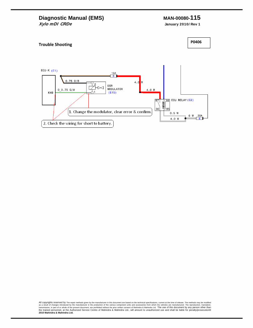
Diagnostic Manual (EMS) MAN-00080-115 Xylo mDI CRDe January 2010/Rev 1
All copyrights reserved by The repair methods given by the manufacturer in this document are based on the technical specifications, current at the time of release. The methods may be modified as a result of changes introduced by the manufacturer in the production of the various component units and accessories from which the vehicles are manufactured. The reproduction, translation, transmission, in part of or whole of the present document, are prohibited without the prior written consent of Mahindra & Mahindra Ltd. The use of this document by any person other than the trained personnel, at the Authorized Service Centre of Mahindra & Mahindra Ltd., will amount to unauthorized use and shall be liable for penalty/prosecution© 2010 Mahindra & Mahindra Ltd.
Trouble Shooting
P0406

Diagnostic Manual (EMS) MAN-00080-116 Xylo mDI CRDe January 2010/Rev 1
All copyrights reserved by The repair methods given by the manufacturer in this document are based on the technical specifications, current at the time of release. The methods may be modified as a result of changes introduced by the manufacturer in the production of the various component units and accessories from which the vehicles are manufactured. The reproduction, translation, transmission, in part of or whole of the present document, are prohibited without the prior written consent of Mahindra & Mahindra Ltd. The use of this document by any person other than the trained personnel, at the Authorized Service Centre of Mahindra & Mahindra Ltd., will amount to unauthorized use and shall be liable for penalty/prosecution© 2010 Mahindra & Mahindra Ltd.
EGR Description A pulse‐width‐modulated signal is output for the Exhaust Gas Recirculation actuator control. Converting the air control output into duty cycle carries this out. The possible defects are short circuit to battery, ground & no load.
DTC Diagnostic item P‐0405 Short circuit to ground
DTC detection condition Probable cause
Background * The ECU checks current flows in the EGR solenoid
drive circuit when the solenoid is ON and OFF. Range of check, set conditions.
* When the EGR solenoid is turned OFF, no surge voltage is detected.
Normal operation When engine is running per the EGR mapping. • System lamp off after 2 sec. Malfunction • The ECU detects short to ground in signal. Reaction • System lamp will blink. • EGR switched off
* Line is short circuit to ground. .
P0405. Short circuit to ground Class: 4. Light blink Reaction: EGR switched off Possible cause: Signal line short to ground
P0405

Diagnostic Manual (EMS) MAN-00080-117 Xylo mDI CRDe January 2010/Rev 1
All copyrights reserved by The repair methods given by the manufacturer in this document are based on the technical specifications, current at the time of release. The methods may be modified as a result of changes introduced by the manufacturer in the production of the various component units and accessories from which the vehicles are manufactured. The reproduction, translation, transmission, in part of or whole of the present document, are prohibited without the prior written consent of Mahindra & Mahindra Ltd. The use of this document by any person other than the trained personnel, at the Authorized Service Centre of Mahindra & Mahindra Ltd., will amount to unauthorized use and shall be liable for penalty/prosecution© 2010 Mahindra & Mahindra Ltd.
P0405
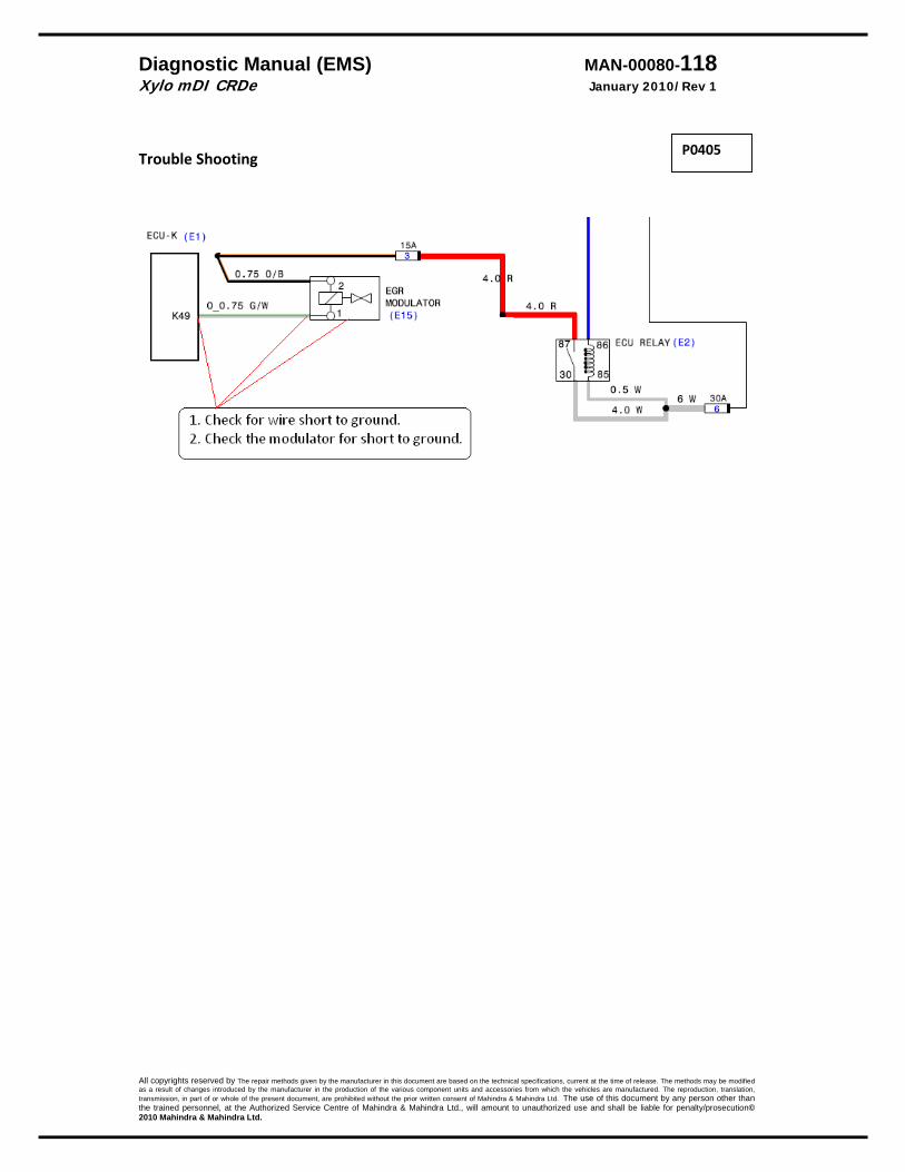
Diagnostic Manual (EMS) MAN-00080-118 Xylo mDI CRDe January 2010/Rev 1
All copyrights reserved by The repair methods given by the manufacturer in this document are based on the technical specifications, current at the time of release. The methods may be modified as a result of changes introduced by the manufacturer in the production of the various component units and accessories from which the vehicles are manufactured. The reproduction, translation, transmission, in part of or whole of the present document, are prohibited without the prior written consent of Mahindra & Mahindra Ltd. The use of this document by any person other than the trained personnel, at the Authorized Service Centre of Mahindra & Mahindra Ltd., will amount to unauthorized use and shall be liable for penalty/prosecution© 2010 Mahindra & Mahindra Ltd.
Trouble Shooting
P0405
Diagnostic Manual (EMS) MAN-00080-119 Xylo mDI CRDe January 2010/Rev 1
All copyrights reserved by The repair methods given by the manufacturer in this document are based on the technical specifications, current at the time of release. The methods may be modified as a result of changes introduced by the manufacturer in the production of the various component units and accessories from which the vehicles are manufactured. The reproduction, translation, transmission, in part of or whole of the present document, are prohibited without the prior written consent of Mahindra & Mahindra Ltd. The use of this document by any person other than the trained personnel, at the Authorized Service Centre of Mahindra & Mahindra Ltd., will amount to unauthorized use and shall be liable for penalty/prosecution© 2010 Mahindra & Mahindra Ltd.
ADC Monitoring Description After the start up, the ECU does the calibration for the ADC. If the calibration can not be done within a predefined time, then it is taken as error. After the ADC calibration the conversion time is checked. If that is taking too long then the conversion time out error is registered
DTC Diagnostic item P‐1700 Calibration time out error P 1701 ADC conversion time out error
DTC detection condition Probable cause
Background * The EMS ECU has a ADC. The same is checked
during start up Normal operation The calibration and the conversions are done within a predefined tim • System lamp off after 2 sec. Malfunction • There is delay in either the calibration or the
conversion time Reaction • System lamp will be continuously ON. • Engine can not be started
* EMS ECU
.
Trouble Shooting Clear the error. Not clearing‐ attempt 3 times. If still present‐ replace the EMS ECU
P1700 P1701
Diagnostic Manual (EMS) MAN-00080-120 Xylo mDI CRDe January 2010/Rev 1
All copyrights reserved by The repair methods given by the manufacturer in this document are based on the technical specifications, current at the time of release. The methods may be modified as a result of changes introduced by the manufacturer in the production of the various component units and accessories from which the vehicles are manufactured. The reproduction, translation, transmission, in part of or whole of the present document, are prohibited without the prior written consent of Mahindra & Mahindra Ltd. The use of this document by any person other than the trained personnel, at the Authorized Service Centre of Mahindra & Mahindra Ltd., will amount to unauthorized use and shall be liable for penalty/prosecution© 2010 Mahindra & Mahindra Ltd.
Fault path of air condition power stage Description – The A/C compressor routes the A/C compressor control signal to the digital power stage output. The power stage is monitored. An error such as short circuit, open circuit or excess temperature, occurring at the power stage is reported. The function routes the control signal for the A/C compressor to the power stage.
DTC Diagnostic item P‐1532 No load
DTC detection condition Probable cause for
malfunction Normal Operation
* AC relay is OFF when the AC switch & blower switch is OFF.
* The ECU checks whether AC switch is ON then it will try to switch ON the AC relay provided blower is ON.
* When AC relay is energized then it will switch ON the AC compressor.
Normal Operation * Ignition switch: ON * Engine is ON * System lamp: OFF after 2Sec * Battery voltage is 8V –16V. * AC switch & blower switches are ON.
Malfunction * ECU not recognizing 12V when AC switch is ON. * ECU output to AC relay has continued to 0.5V or
more. Reaction
* System check lamp will be OFF. * AC will not work.
• Fuse blown. • AC relay • Loose connectors • Open circuit in wire • EMS ECU failure
P-1532

Diagnostic Manual (EMS) MAN-00080-121 Xylo mDI CRDe January 2010/Rev 1
All copyrights reserved by The repair methods given by the manufacturer in this document are based on the technical specifications, current at the time of release. The methods may be modified as a result of changes introduced by the manufacturer in the production of the various component units and accessories from which the vehicles are manufactured. The reproduction, translation, transmission, in part of or whole of the present document, are prohibited without the prior written consent of Mahindra & Mahindra Ltd. The use of this document by any person other than the trained personnel, at the Authorized Service Centre of Mahindra & Mahindra Ltd., will amount to unauthorized use and shall be liable for penalty/prosecution© 2010 Mahindra & Mahindra Ltd.
P-1532 P-1532
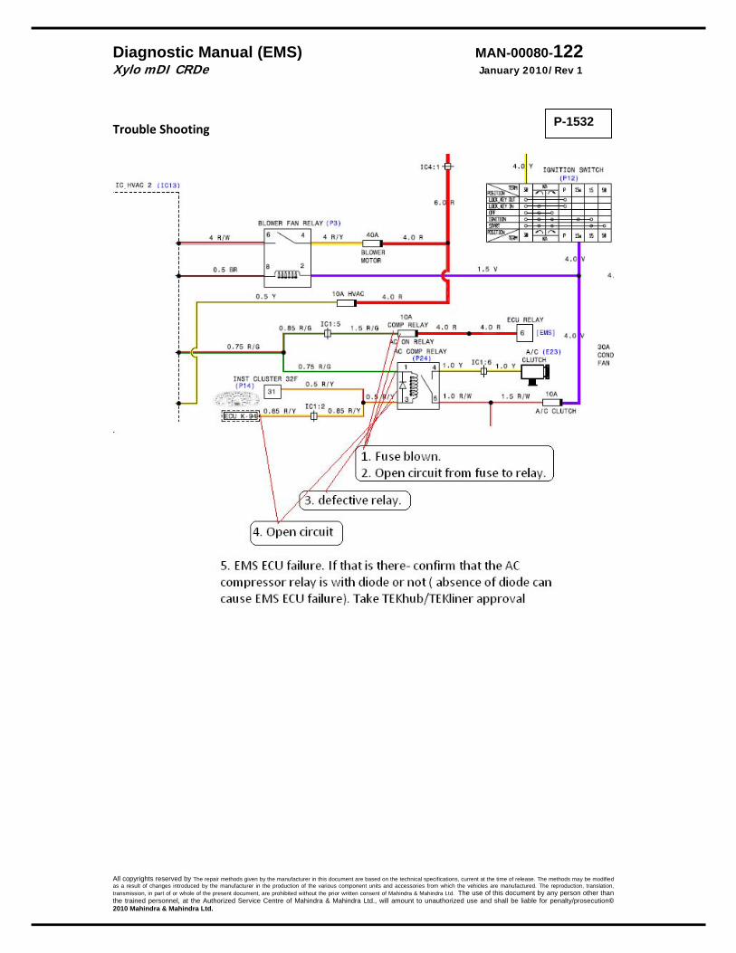
Diagnostic Manual (EMS) MAN-00080-122 Xylo mDI CRDe January 2010/Rev 1
All copyrights reserved by The repair methods given by the manufacturer in this document are based on the technical specifications, current at the time of release. The methods may be modified as a result of changes introduced by the manufacturer in the production of the various component units and accessories from which the vehicles are manufactured. The reproduction, translation, transmission, in part of or whole of the present document, are prohibited without the prior written consent of Mahindra & Mahindra Ltd. The use of this document by any person other than the trained personnel, at the Authorized Service Centre of Mahindra & Mahindra Ltd., will amount to unauthorized use and shall be liable for penalty/prosecution© 2010 Mahindra & Mahindra Ltd.
Trouble Shooting
P-1532
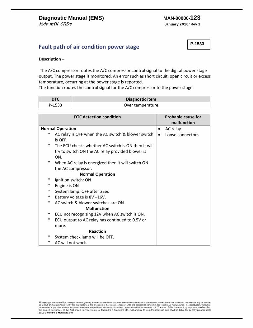
Diagnostic Manual (EMS) MAN-00080-123 Xylo mDI CRDe January 2010/Rev 1
All copyrights reserved by The repair methods given by the manufacturer in this document are based on the technical specifications, current at the time of release. The methods may be modified as a result of changes introduced by the manufacturer in the production of the various component units and accessories from which the vehicles are manufactured. The reproduction, translation, transmission, in part of or whole of the present document, are prohibited without the prior written consent of Mahindra & Mahindra Ltd. The use of this document by any person other than the trained personnel, at the Authorized Service Centre of Mahindra & Mahindra Ltd., will amount to unauthorized use and shall be liable for penalty/prosecution© 2010 Mahindra & Mahindra Ltd.
Fault path of air condition power stage Description – The A/C compressor routes the A/C compressor control signal to the digital power stage output. The power stage is monitored. An error such as short circuit, open circuit or excess temperature, occurring at the power stage is reported. The function routes the control signal for the A/C compressor to the power stage.
DTC Diagnostic item P‐1533 Over temperature
DTC detection condition Probable cause for
malfunction Normal Operation
* AC relay is OFF when the AC switch & blower switch is OFF.
* The ECU checks whether AC switch is ON then it will try to switch ON the AC relay provided blower is ON.
* When AC relay is energized then it will switch ON the AC compressor.
Normal Operation * Ignition switch: ON * Engine is ON * System lamp: OFF after 2Sec * Battery voltage is 8V –16V. * AC switch & blower switches are ON.
Malfunction * ECU not recognizing 12V when AC switch is ON. * ECU output to AC relay has continued to 0.5V or
more. Reaction
* System check lamp will be OFF. * AC will not work.
• AC relay • Loose connectors
P-1533
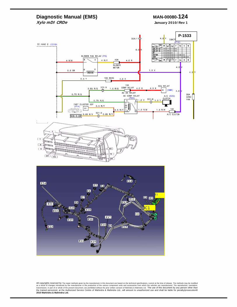
Diagnostic Manual (EMS) MAN-00080-124 Xylo mDI CRDe January 2010/Rev 1
All copyrights reserved by The repair methods given by the manufacturer in this document are based on the technical specifications, current at the time of release. The methods may be modified as a result of changes introduced by the manufacturer in the production of the various component units and accessories from which the vehicles are manufactured. The reproduction, translation, transmission, in part of or whole of the present document, are prohibited without the prior written consent of Mahindra & Mahindra Ltd. The use of this document by any person other than the trained personnel, at the Authorized Service Centre of Mahindra & Mahindra Ltd., will amount to unauthorized use and shall be liable for penalty/prosecution© 2010 Mahindra & Mahindra Ltd.
P-1533
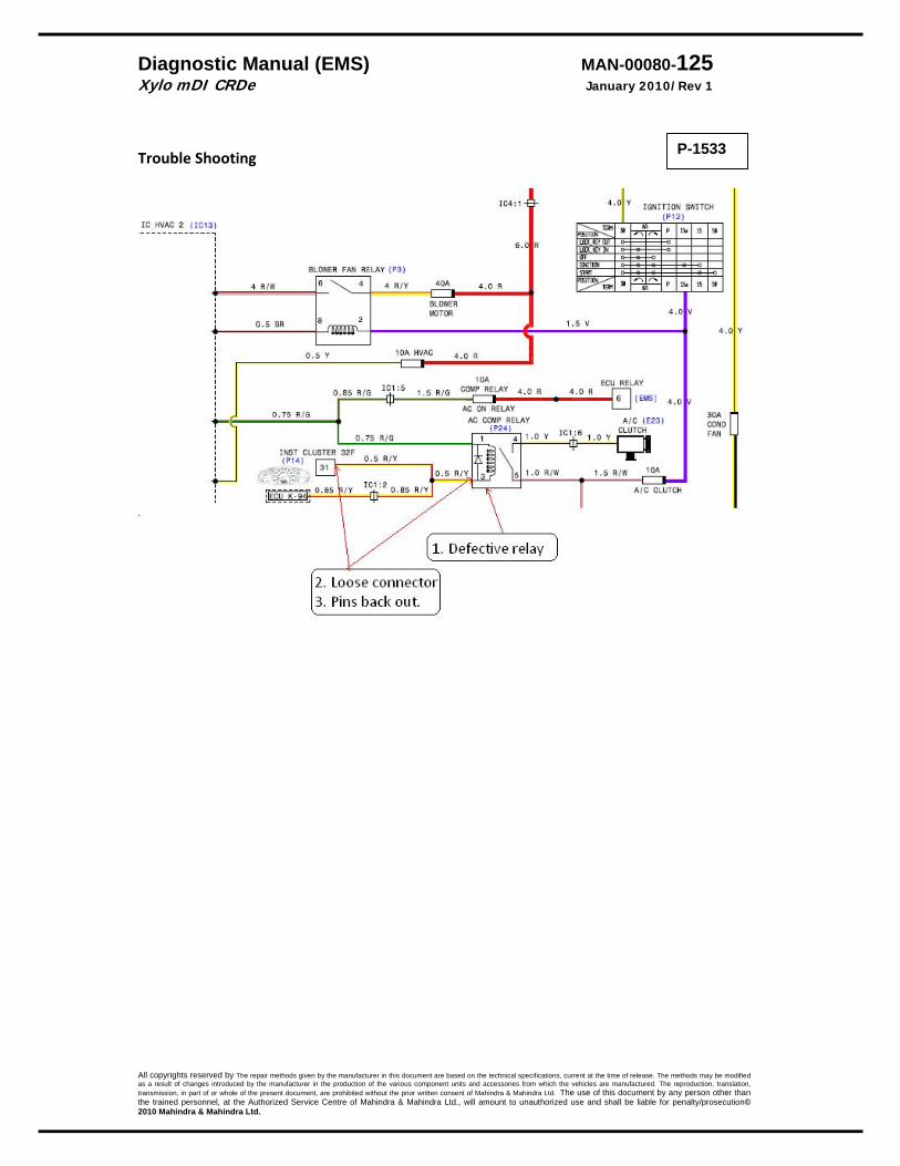
Diagnostic Manual (EMS) MAN-00080-125 Xylo mDI CRDe January 2010/Rev 1
All copyrights reserved by The repair methods given by the manufacturer in this document are based on the technical specifications, current at the time of release. The methods may be modified as a result of changes introduced by the manufacturer in the production of the various component units and accessories from which the vehicles are manufactured. The reproduction, translation, transmission, in part of or whole of the present document, are prohibited without the prior written consent of Mahindra & Mahindra Ltd. The use of this document by any person other than the trained personnel, at the Authorized Service Centre of Mahindra & Mahindra Ltd., will amount to unauthorized use and shall be liable for penalty/prosecution© 2010 Mahindra & Mahindra Ltd.
Trouble Shooting
P-1533

Diagnostic Manual (EMS) MAN-00080-126 Xylo mDI CRDe January 2010/Rev 1
All copyrights reserved by The repair methods given by the manufacturer in this document are based on the technical specifications, current at the time of release. The methods may be modified as a result of changes introduced by the manufacturer in the production of the various component units and accessories from which the vehicles are manufactured. The reproduction, translation, transmission, in part of or whole of the present document, are prohibited without the prior written consent of Mahindra & Mahindra Ltd. The use of this document by any person other than the trained personnel, at the Authorized Service Centre of Mahindra & Mahindra Ltd., will amount to unauthorized use and shall be liable for penalty/prosecution© 2010 Mahindra & Mahindra Ltd.
Fault path of air condition power stage Description – The A/C compressor routes the A/C compressor control signal to the digital power stage output. The power stage is monitored. An error such as short circuit, open circuit or excess temperature, occurring at the power stage is reported. The function routes the control signal for the A/C compressor to the power stage.
DTC Diagnostic item P‐1530 Short circuit to battery. P 1531 Short circuit to ground.
DTC detection condition Probable cause for
malfunction Normal Operation
* AC relay is OFF when the AC switch & blower switch is OFF.
* The ECU checks whether AC switch is ON then it will try to switch ON the AC relay provided blower is ON.
* When AC relay is energized then it will switch ON the AC compressor.
Normal Operation * Ignition switch: ON * Engine is ON * System lamp: OFF after 2Sec * Battery voltage is 8V –16V. * AC switch & blower switches are ON.
Malfunction * ECU recognizes that the power stage is short to
battery or short to ground Reaction
* System check lamp will be OFF. * AC will not work.
• Short to Battery − Output from relay
shorted to Batt − Relay
• Short to ground
P-1530 P 1531

Diagnostic Manual (EMS) MAN-00080-127 Xylo mDI CRDe January 2010/Rev 1
All copyrights reserved by The repair methods given by the manufacturer in this document are based on the technical specifications, current at the time of release. The methods may be modified as a result of changes introduced by the manufacturer in the production of the various component units and accessories from which the vehicles are manufactured. The reproduction, translation, transmission, in part of or whole of the present document, are prohibited without the prior written consent of Mahindra & Mahindra Ltd. The use of this document by any person other than the trained personnel, at the Authorized Service Centre of Mahindra & Mahindra Ltd., will amount to unauthorized use and shall be liable for penalty/prosecution© 2010 Mahindra & Mahindra Ltd.
P-1530 P 1531

Diagnostic Manual (EMS) MAN-00080-128 Xylo mDI CRDe January 2010/Rev 1
All copyrights reserved by The repair methods given by the manufacturer in this document are based on the technical specifications, current at the time of release. The methods may be modified as a result of changes introduced by the manufacturer in the production of the various component units and accessories from which the vehicles are manufactured. The reproduction, translation, transmission, in part of or whole of the present document, are prohibited without the prior written consent of Mahindra & Mahindra Ltd. The use of this document by any person other than the trained personnel, at the Authorized Service Centre of Mahindra & Mahindra Ltd., will amount to unauthorized use and shall be liable for penalty/prosecution© 2010 Mahindra & Mahindra Ltd.
Trouble Shooting P 1530
P 1531
P-1530 P 1531

Diagnostic Manual (EMS) MAN-00080-129 Xylo mDI CRDe January 2010/Rev 1
All copyrights reserved by The repair methods given by the manufacturer in this document are based on the technical specifications, current at the time of release. The methods may be modified as a result of changes introduced by the manufacturer in the production of the various component units and accessories from which the vehicles are manufactured. The reproduction, translation, transmission, in part of or whole of the present document, are prohibited without the prior written consent of Mahindra & Mahindra Ltd. The use of this document by any person other than the trained personnel, at the Authorized Service Centre of Mahindra & Mahindra Ltd., will amount to unauthorized use and shall be liable for penalty/prosecution© 2010 Mahindra & Mahindra Ltd.
Battery Description: The system voltage has to guarantee to perform diagnosis functions. The Electronic Control Unit (ECU) monitors battery voltage..
DTC Diagnostic itemP‐0563 P‐0562
SRC Max SRC Min
DTC detection condition Probable cause Detecting Condition
P 0563 P 0562
If Battery Voltage >16.5 Battery Voltage < 8 Volts
Reaction
P 0563 P 0562
Check lamp glows
All Actuators switched off.
EMS ECU switches off
Check lamp glows
Below 10 V‐ EGR off,
Below 11 V‐ ZFC off
Below 10.5 V‐ AC off.
Below 10.5 V‐ Low idle speed is 900 RPM
Below 8 V‐ EMS ECU switches off
P0563 • High charging
circuit. • Loose
connection in charging circuit.
• Wrong battery P0562 • Charging circuit • Leakage current • Battery
condition • Earthing
Test Procedure Battery –
1. Check charging system ( including alternator). 2. Check charging system (including battery) for proper operation. 3. Check if the battery is of the correct specification 4. Refer the charging system section in the Electrical. 5. Charging system OK. ( Voltage during cranking should be at least 9 volts) 6. Check earthing ( near the battery‐ clean the contact and fender for excess
paint/rust
P‐0563 P‐0562

Diagnostic Manual (EMS) MAN-00080-130 Xylo mDI CRDe January 2010/Rev 1
All copyrights reserved by The repair methods given by the manufacturer in this document are based on the technical specifications, current at the time of release. The methods may be modified as a result of changes introduced by the manufacturer in the production of the various component units and accessories from which the vehicles are manufactured. The reproduction, translation, transmission, in part of or whole of the present document, are prohibited without the prior written consent of Mahindra & Mahindra Ltd. The use of this document by any person other than the trained personnel, at the Authorized Service Centre of Mahindra & Mahindra Ltd., will amount to unauthorized use and shall be liable for penalty/prosecution© 2010 Mahindra & Mahindra Ltd.
ECU Communication Monitoring Description: Communication between controller and power stage inside the ECU is not OK
DTC Diagnostic item P‐162A Communication error of CJ940
DTC detection condition Probable cause for
malfunction Normal Operation
The SPI‐communication is monitored by the CY320 driver.And the chceck sum data is correct.
* . Malfunction
A fault is detected if the received data has incorrect check‐bytes or a data transfer is not possible.
Reaction * System check lamp will be OFF. * ECU off‐ which means engine is OFF. * Restart not possible
• Chip failure.
Reaction: The System Check lamp will be continuously ON. Test Procedure: 1. Switch ON Ignition 2. Using smart tester, clear the ECU faults. 3. Switch OFF Ignition key and wait for 2 minutes. 4. Switch ON Ignition. 5. Using smart tester check whether any of the above mentioned fault is present. 6. If fault is still present, switch OFF ignition. 7. Replace the ECU with a new one and repeat steps 4 & 5. 8. If fault is not present in the new ECU, then the old ECU is defective and has to be sent
back to M&M. 9. Note : Please send CrFr and get approval before step 8
P‐162A

Diagnostic Manual (EMS) MAN-00080-131 Xylo mDI CRDe January 2010/Rev 1
All copyrights reserved by The repair methods given by the manufacturer in this document are based on the technical specifications, current at the time of release. The methods may be modified as a result of changes introduced by the manufacturer in the production of the various component units and accessories from which the vehicles are manufactured. The reproduction, translation, transmission, in part of or whole of the present document, are prohibited without the prior written consent of Mahindra & Mahindra Ltd. The use of this document by any person other than the trained personnel, at the Authorized Service Centre of Mahindra & Mahindra Ltd., will amount to unauthorized use and shall be liable for penalty/prosecution© 2010 Mahindra & Mahindra Ltd.
ECU EEPROM Monitoring Description: EEPROM storage device inside ECU is not OK
DTC Diagnostic itemP‐162B P‐162C P‐162D
EEPROM: flash error during last read operation EEPROM: read error during last write operation
EEPROM: write error default value used
DTC detection condition Probable cause for malfunction
Normal Operation During normal operation during shut down the EEPROM can be flashed, read & written‐ this happens during the overrun period.
. Malfunction
P 162B If any sector erase can not happen. P 162C If at least 3 sector can not be read . P 162D If one block can not be written at
least – 3 attempt
Reaction * System check lamp will be OFF. * ECU off‐ which means engine is OFF. * Restart not possible
• EEPROM failure
Reaction: The System Check lamp will be continuously ON. Test Procedure: 1. Switch ON Ignition. 2. Using ‘Smart Tester’, clear the ECU faults. 3. Switch OFF Ignition key and wait for 2 minutes. 4. Switch ON Ignition. 5. Using smart tester check whether any of the above mentioned fault is present. 6. If fault is still present, switch OFF ignition. 7. Replace the ECU with a new one and repeat steps 4 & 5. 8. If fault is not present in the new ECU, then the old ECU is defective and has to be sent
back to M&M. 9. Note : Please send CrFr and get approval before step 8
P‐162B P‐162C P‐162D

Diagnostic Manual (EMS) MAN-00080-132 Xylo mDI CRDe January 2010/Rev 1
All copyrights reserved by The repair methods given by the manufacturer in this document are based on the technical specifications, current at the time of release. The methods may be modified as a result of changes introduced by the manufacturer in the production of the various component units and accessories from which the vehicles are manufactured. The reproduction, translation, transmission, in part of or whole of the present document, are prohibited without the prior written consent of Mahindra & Mahindra Ltd. The use of this document by any person other than the trained personnel, at the Authorized Service Centre of Mahindra & Mahindra Ltd., will amount to unauthorized use and shall be liable for penalty/prosecution© 2010 Mahindra & Mahindra Ltd.
ECU ICO Monitoring Description: Communication between controller and power stage inside the ECU is not OK
DTC Diagnostic item P‐1670 Engine ICO ( Injection Cut Off)
DTC detection condition Probable cause for
malfunction Normal Operation
During the ICO no injection is taking place Malfunction
* during the overrun monitoring it observes that the injection is taking place (when it is not supposed to do so, it takes cognisance of the injections which are supposed to take place due to ZFC and FBC, this is above that). If it is more than 8 times then the reaction is injection cut off..
Reaction * System check lamp will be ON. * ECU off‐ which means engine is OFF. * Restart not possible
• ECU failure.
Reaction: The System Check lamp will be continuously ON. Test Procedure:
1. Switch ON Ignition 2. Using smart tester, clear the ECU faults. 3. Switch OFF Ignition key and wait for 2 minutes. 4. Switch ON Ignition. 5. Using smart tester check whether any of the above mentioned fault is present. 6. If fault is still present, switch OFF ignition. 7. Replace the ECU with a new one and repeat steps 4 & 5. 8. If fault is not present in the new ECU, then the old ECU is defective and has to be
sent back to M&M. 9. Note : Please send CrFr and get approval before step 8
.
P‐1670
Diagnostic Manual (EMS) MAN-00080-133 Xylo mDI CRDe January 2010/Rev 1
All copyrights reserved by The repair methods given by the manufacturer in this document are based on the technical specifications, current at the time of release. The methods may be modified as a result of changes introduced by the manufacturer in the production of the various component units and accessories from which the vehicles are manufactured. The reproduction, translation, transmission, in part of or whole of the present document, are prohibited without the prior written consent of Mahindra & Mahindra Ltd. The use of this document by any person other than the trained personnel, at the Authorized Service Centre of Mahindra & Mahindra Ltd., will amount to unauthorized use and shall be liable for penalty/prosecution© 2010 Mahindra & Mahindra Ltd.
ECU IQA Monitoring Description: Communication between controller and power stage inside the ECU is not OK
DTC Diagnostic item P1737 Check of missing injector adjustment value programming‐ Injector 1 P1738 Check of missing injector adjustment value programming‐ Injector 2 P1739 Check of missing injector adjustment value programming‐ Injector 3 P1740 Check of missing injector adjustment value programming‐ Injector 4
DTC detection condition Probable cause for
malfunction Normal Operation
During the ICO no injection is taking place Malfunction
* during the overrun monitoring it observes that the injection is taking place (when it is not supposed to do so, it takes cognisance of the injections which are supposed to take place due to ZFC and FBC, this is above that). If it is more than 8 times then the reaction is injection cut off..
Reaction * System check lamp will be ON. *
• If the IQA code is not entered.
• ECU defective
Trouble Shooting
1. If ECU replaced and not able to enter the IQA values. If the same IQA values can be entered in any other ECU then the complaint is ECU. Replace the ECU. However approval of the TEKliner / TEKhub is compulsory. Submit report in CrFR
Note : The IQA code is a 6 digit code.
P 1737 P 1738 P 1739 P 1740
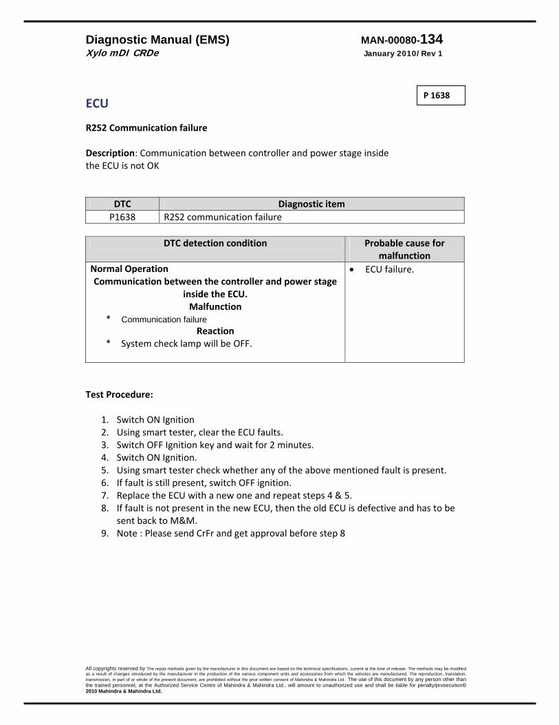
Diagnostic Manual (EMS) MAN-00080-134 Xylo mDI CRDe January 2010/Rev 1
All copyrights reserved by The repair methods given by the manufacturer in this document are based on the technical specifications, current at the time of release. The methods may be modified as a result of changes introduced by the manufacturer in the production of the various component units and accessories from which the vehicles are manufactured. The reproduction, translation, transmission, in part of or whole of the present document, are prohibited without the prior written consent of Mahindra & Mahindra Ltd. The use of this document by any person other than the trained personnel, at the Authorized Service Centre of Mahindra & Mahindra Ltd., will amount to unauthorized use and shall be liable for penalty/prosecution© 2010 Mahindra & Mahindra Ltd.
ECU R2S2 Communication failure Description: Communication between controller and power stage inside the ECU is not OK
DTC Diagnostic item P1638 R2S2 communication failure
DTC detection condition Probable cause for
malfunction Normal Operation Communication between the controller and power stage
inside the ECU. Malfunction
* Communication failure Reaction
* System check lamp will be OFF.
• ECU failure.
Test Procedure:
1. Switch ON Ignition 2. Using smart tester, clear the ECU faults. 3. Switch OFF Ignition key and wait for 2 minutes. 4. Switch ON Ignition. 5. Using smart tester check whether any of the above mentioned fault is present. 6. If fault is still present, switch OFF ignition. 7. Replace the ECU with a new one and repeat steps 4 & 5. 8. If fault is not present in the new ECU, then the old ECU is defective and has to be
sent back to M&M. 9. Note : Please send CrFr and get approval before step 8
P 1638
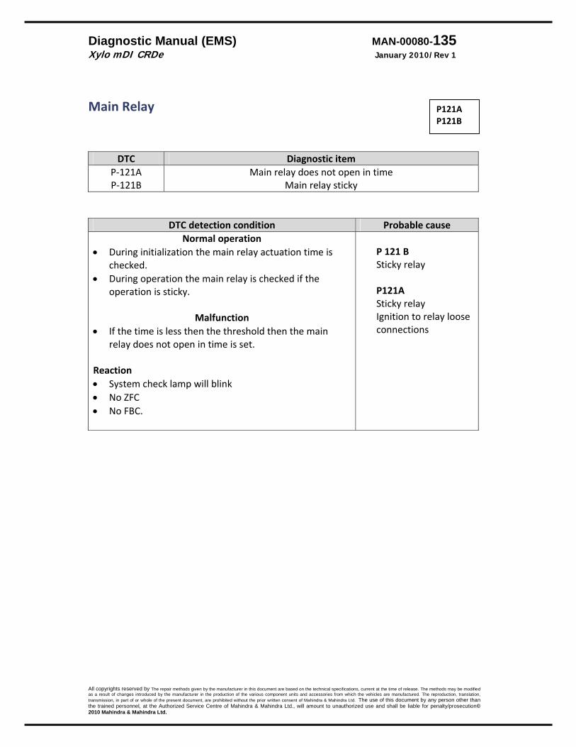
Diagnostic Manual (EMS) MAN-00080-135 Xylo mDI CRDe January 2010/Rev 1
All copyrights reserved by The repair methods given by the manufacturer in this document are based on the technical specifications, current at the time of release. The methods may be modified as a result of changes introduced by the manufacturer in the production of the various component units and accessories from which the vehicles are manufactured. The reproduction, translation, transmission, in part of or whole of the present document, are prohibited without the prior written consent of Mahindra & Mahindra Ltd. The use of this document by any person other than the trained personnel, at the Authorized Service Centre of Mahindra & Mahindra Ltd., will amount to unauthorized use and shall be liable for penalty/prosecution© 2010 Mahindra & Mahindra Ltd.
Main Relay
DTC Diagnostic itemP‐121A P‐121B
Main relay does not open in time Main relay sticky
DTC detection condition Probable cause Normal operation
• During initialization the main relay actuation time is checked.
• During operation the main relay is checked if the operation is sticky.
Malfunction • If the time is less then the threshold then the main
relay does not open in time is set. Reaction • System check lamp will blink • No ZFC • No FBC.
P 121 B Sticky relay P121A Sticky relay Ignition to relay loose connections
P121A P121B
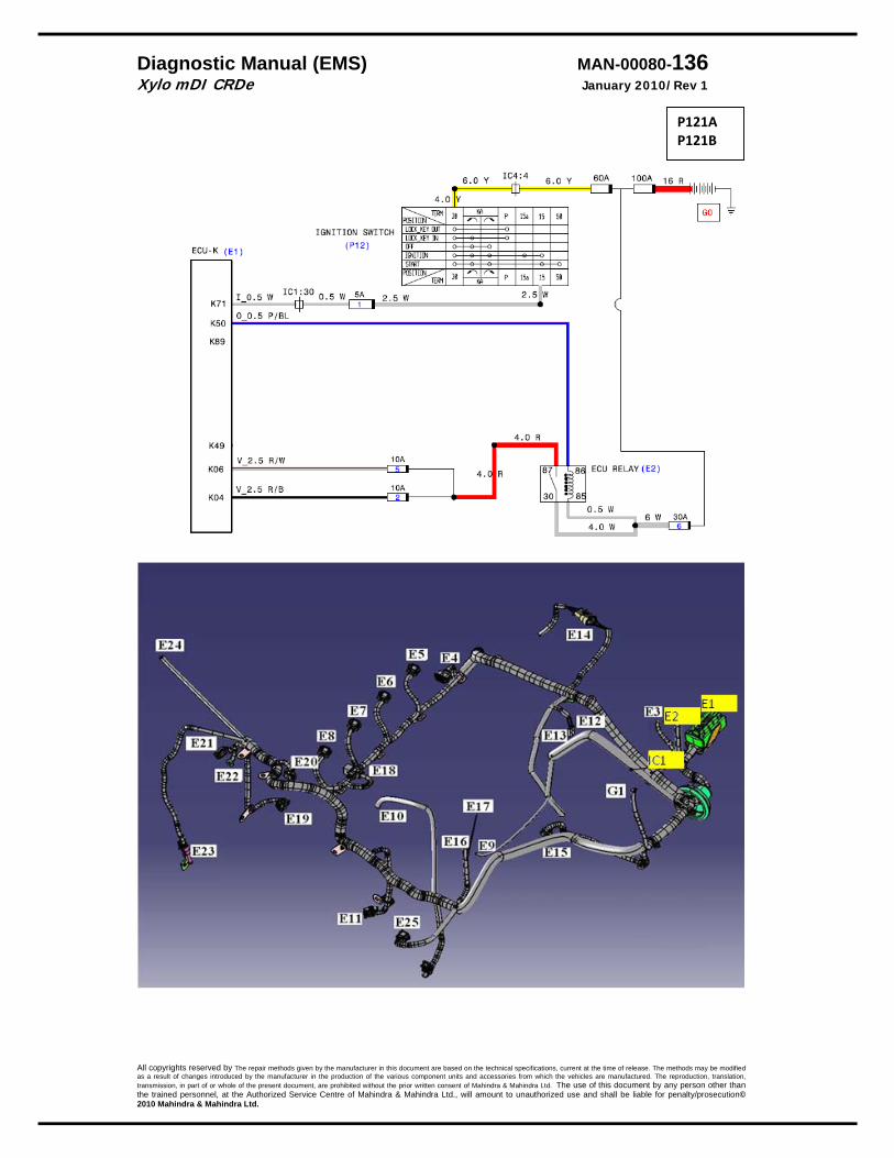
Diagnostic Manual (EMS) MAN-00080-136 Xylo mDI CRDe January 2010/Rev 1
All copyrights reserved by The repair methods given by the manufacturer in this document are based on the technical specifications, current at the time of release. The methods may be modified as a result of changes introduced by the manufacturer in the production of the various component units and accessories from which the vehicles are manufactured. The reproduction, translation, transmission, in part of or whole of the present document, are prohibited without the prior written consent of Mahindra & Mahindra Ltd. The use of this document by any person other than the trained personnel, at the Authorized Service Centre of Mahindra & Mahindra Ltd., will amount to unauthorized use and shall be liable for penalty/prosecution© 2010 Mahindra & Mahindra Ltd.
P121A P121B
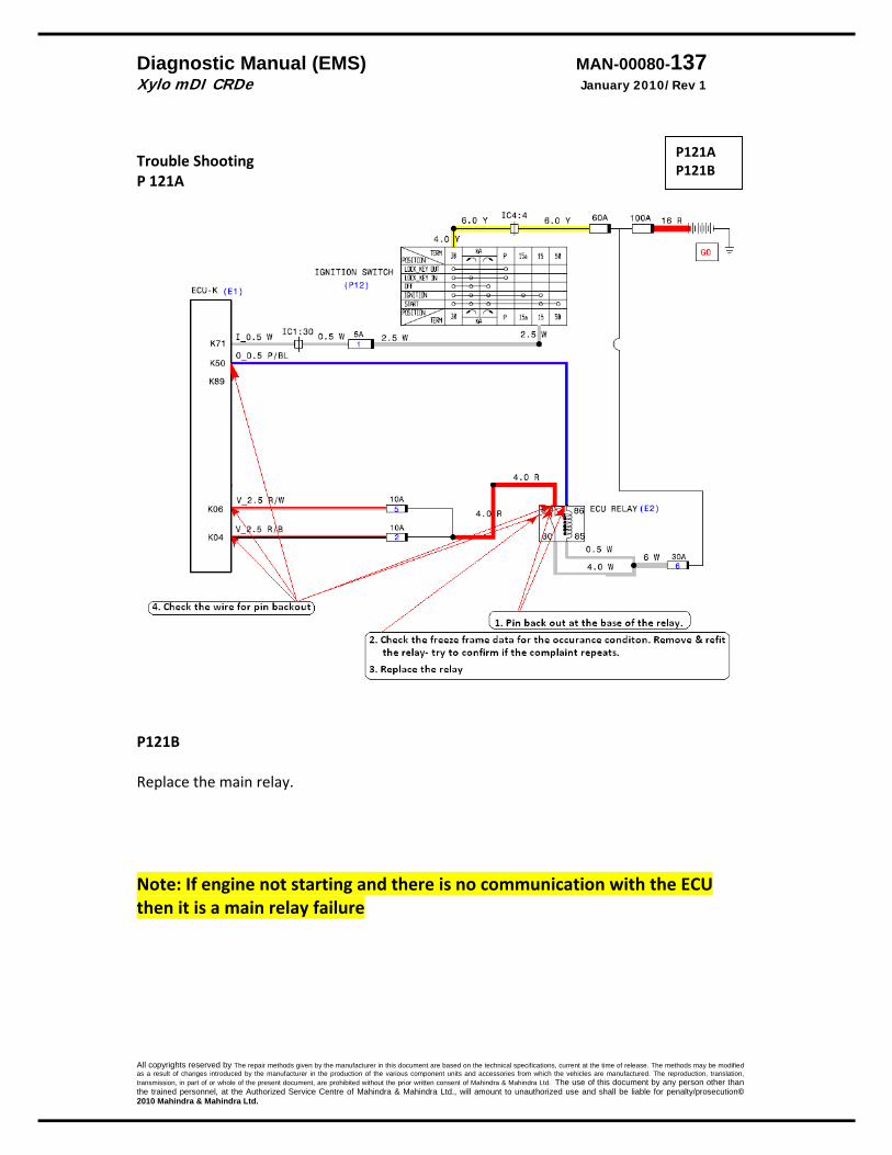
Diagnostic Manual (EMS) MAN-00080-137 Xylo mDI CRDe January 2010/Rev 1
All copyrights reserved by The repair methods given by the manufacturer in this document are based on the technical specifications, current at the time of release. The methods may be modified as a result of changes introduced by the manufacturer in the production of the various component units and accessories from which the vehicles are manufactured. The reproduction, translation, transmission, in part of or whole of the present document, are prohibited without the prior written consent of Mahindra & Mahindra Ltd. The use of this document by any person other than the trained personnel, at the Authorized Service Centre of Mahindra & Mahindra Ltd., will amount to unauthorized use and shall be liable for penalty/prosecution© 2010 Mahindra & Mahindra Ltd.
Trouble Shooting P 121A
P121B Replace the main relay. Note: If engine not starting and there is no communication with the ECU then it is a main relay failure
P121A P121B
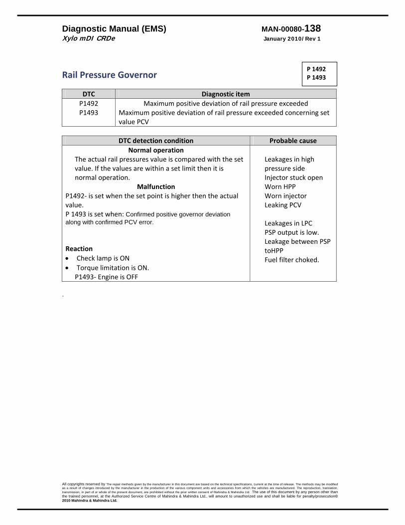
Diagnostic Manual (EMS) MAN-00080-138 Xylo mDI CRDe January 2010/Rev 1
All copyrights reserved by The repair methods given by the manufacturer in this document are based on the technical specifications, current at the time of release. The methods may be modified as a result of changes introduced by the manufacturer in the production of the various component units and accessories from which the vehicles are manufactured. The reproduction, translation, transmission, in part of or whole of the present document, are prohibited without the prior written consent of Mahindra & Mahindra Ltd. The use of this document by any person other than the trained personnel, at the Authorized Service Centre of Mahindra & Mahindra Ltd., will amount to unauthorized use and shall be liable for penalty/prosecution© 2010 Mahindra & Mahindra Ltd.
Rail Pressure Governor
DTC Diagnostic itemP1492 P1493
Maximum positive deviation of rail pressure exceeded Maximum positive deviation of rail pressure exceeded concerning set value PCV
DTC detection condition Probable cause
Normal operation The actual rail pressures value is compared with the set value. If the values are within a set limit then it is normal operation.
Malfunction P1492‐ is set when the set point is higher then the actual value. P 1493 is set when: Confirmed positive governor deviation along with confirmed PCV error. Reaction • Check lamp is ON • Torque limitation is ON.
P1493‐ Engine is OFF
Leakages in high pressure side Injector stuck open Worn HPP Worn injector Leaking PCV Leakages in LPC PSP output is low. Leakage between PSP toHPP Fuel filter choked.
.
P 1492 P 1493
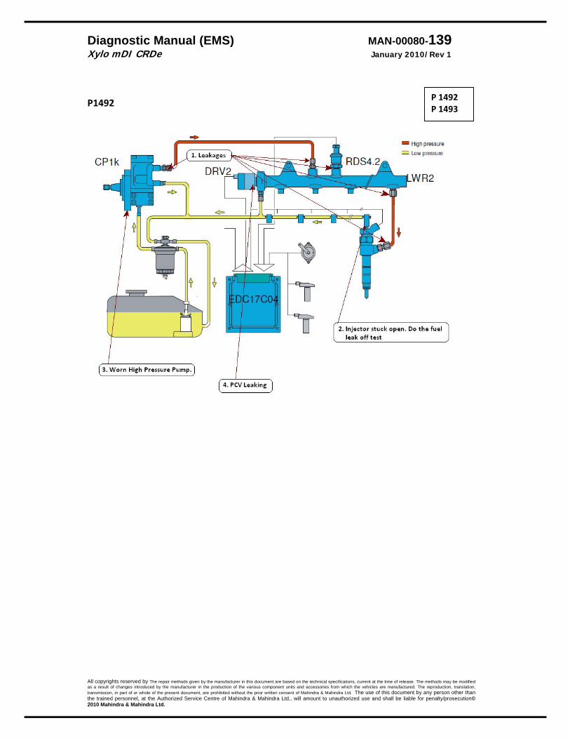
Diagnostic Manual (EMS) MAN-00080-139 Xylo mDI CRDe January 2010/Rev 1
All copyrights reserved by The repair methods given by the manufacturer in this document are based on the technical specifications, current at the time of release. The methods may be modified as a result of changes introduced by the manufacturer in the production of the various component units and accessories from which the vehicles are manufactured. The reproduction, translation, transmission, in part of or whole of the present document, are prohibited without the prior written consent of Mahindra & Mahindra Ltd. The use of this document by any person other than the trained personnel, at the Authorized Service Centre of Mahindra & Mahindra Ltd., will amount to unauthorized use and shall be liable for penalty/prosecution© 2010 Mahindra & Mahindra Ltd.
P1492
P 1492 P 1493

Diagnostic Manual (EMS) MAN-00080-140 Xylo mDI CRDe January 2010/Rev 1
All copyrights reserved by The repair methods given by the manufacturer in this document are based on the technical specifications, current at the time of release. The methods may be modified as a result of changes introduced by the manufacturer in the production of the various component units and accessories from which the vehicles are manufactured. The reproduction, translation, transmission, in part of or whole of the present document, are prohibited without the prior written consent of Mahindra & Mahindra Ltd. The use of this document by any person other than the trained personnel, at the Authorized Service Centre of Mahindra & Mahindra Ltd., will amount to unauthorized use and shall be liable for penalty/prosecution© 2010 Mahindra & Mahindra Ltd.
P 1493
P 1492 P 1493
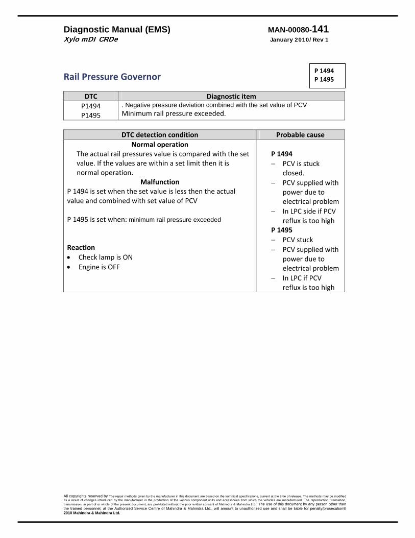
Diagnostic Manual (EMS) MAN-00080-141 Xylo mDI CRDe January 2010/Rev 1
All copyrights reserved by The repair methods given by the manufacturer in this document are based on the technical specifications, current at the time of release. The methods may be modified as a result of changes introduced by the manufacturer in the production of the various component units and accessories from which the vehicles are manufactured. The reproduction, translation, transmission, in part of or whole of the present document, are prohibited without the prior written consent of Mahindra & Mahindra Ltd. The use of this document by any person other than the trained personnel, at the Authorized Service Centre of Mahindra & Mahindra Ltd., will amount to unauthorized use and shall be liable for penalty/prosecution© 2010 Mahindra & Mahindra Ltd.
Rail Pressure Governor
DTC Diagnostic itemP1494 P1495
. Negative pressure deviation combined with the set value of PCV Minimum rail pressure exceeded.
DTC detection condition Probable cause
Normal operation The actual rail pressures value is compared with the set value. If the values are within a set limit then it is normal operation.
Malfunction P 1494 is set when the set value is less then the actual value and combined with set value of PCV P 1495 is set when: minimum rail pressure exceeded Reaction • Check lamp is ON • Engine is OFF
P 1494 − PCV is stuck
closed. − PCV supplied with
power due to electrical problem
− In LPC side if PCV reflux is too high
P 1495 − PCV stuck − PCV supplied with
power due to electrical problem
− In LPC if PCV reflux is too high
P 1494 P 1495
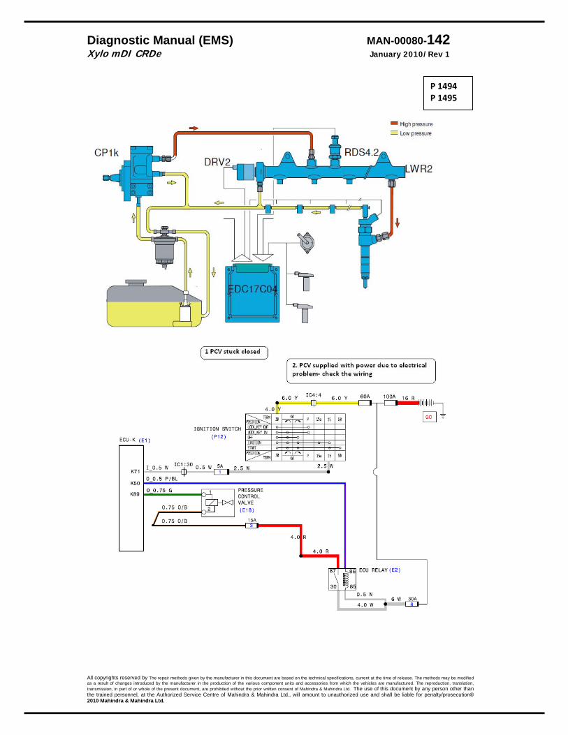
Diagnostic Manual (EMS) MAN-00080-142 Xylo mDI CRDe January 2010/Rev 1
All copyrights reserved by The repair methods given by the manufacturer in this document are based on the technical specifications, current at the time of release. The methods may be modified as a result of changes introduced by the manufacturer in the production of the various component units and accessories from which the vehicles are manufactured. The reproduction, translation, transmission, in part of or whole of the present document, are prohibited without the prior written consent of Mahindra & Mahindra Ltd. The use of this document by any person other than the trained personnel, at the Authorized Service Centre of Mahindra & Mahindra Ltd., will amount to unauthorized use and shall be liable for penalty/prosecution© 2010 Mahindra & Mahindra Ltd.
P 1494 P 1495
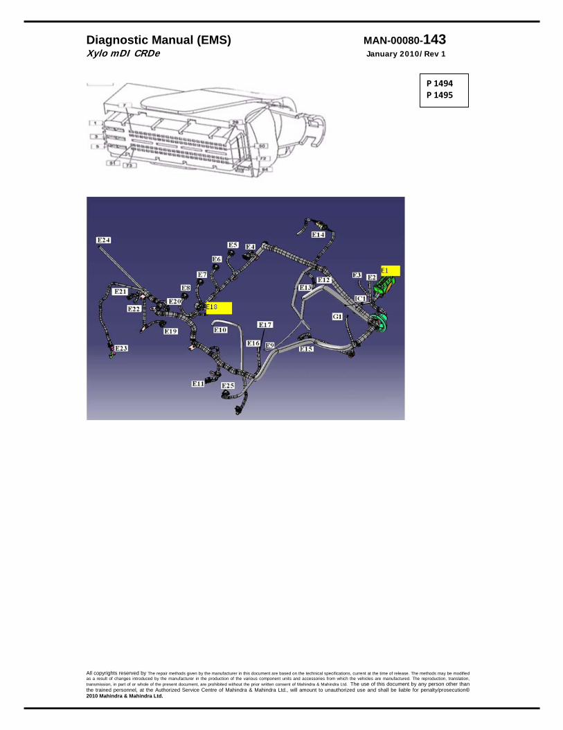
Diagnostic Manual (EMS) MAN-00080-143 Xylo mDI CRDe January 2010/Rev 1
All copyrights reserved by The repair methods given by the manufacturer in this document are based on the technical specifications, current at the time of release. The methods may be modified as a result of changes introduced by the manufacturer in the production of the various component units and accessories from which the vehicles are manufactured. The reproduction, translation, transmission, in part of or whole of the present document, are prohibited without the prior written consent of Mahindra & Mahindra Ltd. The use of this document by any person other than the trained personnel, at the Authorized Service Centre of Mahindra & Mahindra Ltd., will amount to unauthorized use and shall be liable for penalty/prosecution© 2010 Mahindra & Mahindra Ltd.
P 1494 P 1495

Diagnostic Manual (EMS) MAN-00080-144 Xylo mDI CRDe January 2010/Rev 1
All copyrights reserved by The repair methods given by the manufacturer in this document are based on the technical specifications, current at the time of release. The methods may be modified as a result of changes introduced by the manufacturer in the production of the various component units and accessories from which the vehicles are manufactured. The reproduction, translation, transmission, in part of or whole of the present document, are prohibited without the prior written consent of Mahindra & Mahindra Ltd. The use of this document by any person other than the trained personnel, at the Authorized Service Centre of Mahindra & Mahindra Ltd., will amount to unauthorized use and shall be liable for penalty/prosecution© 2010 Mahindra & Mahindra Ltd.
Rail Pressure Governor
DTC Diagnostic itemP 1496 Minimum rail pressure exceeded.
DTC detection condition Probable cause
Normal operation The rail pressure is normal based on the engine speed.
Malfunction If the rail pressure falls below the threshold based on the engine speed then this error is set. Reaction • Check lamp is ON • Engine is OFF
High Pressure Side Leakages Injection nozzle stuck in open Worn HPP Worn injector Leaking PCV Low Pressure Side Leakage EPK pump output less Filter clogged
Trouble Shooting
P 1496
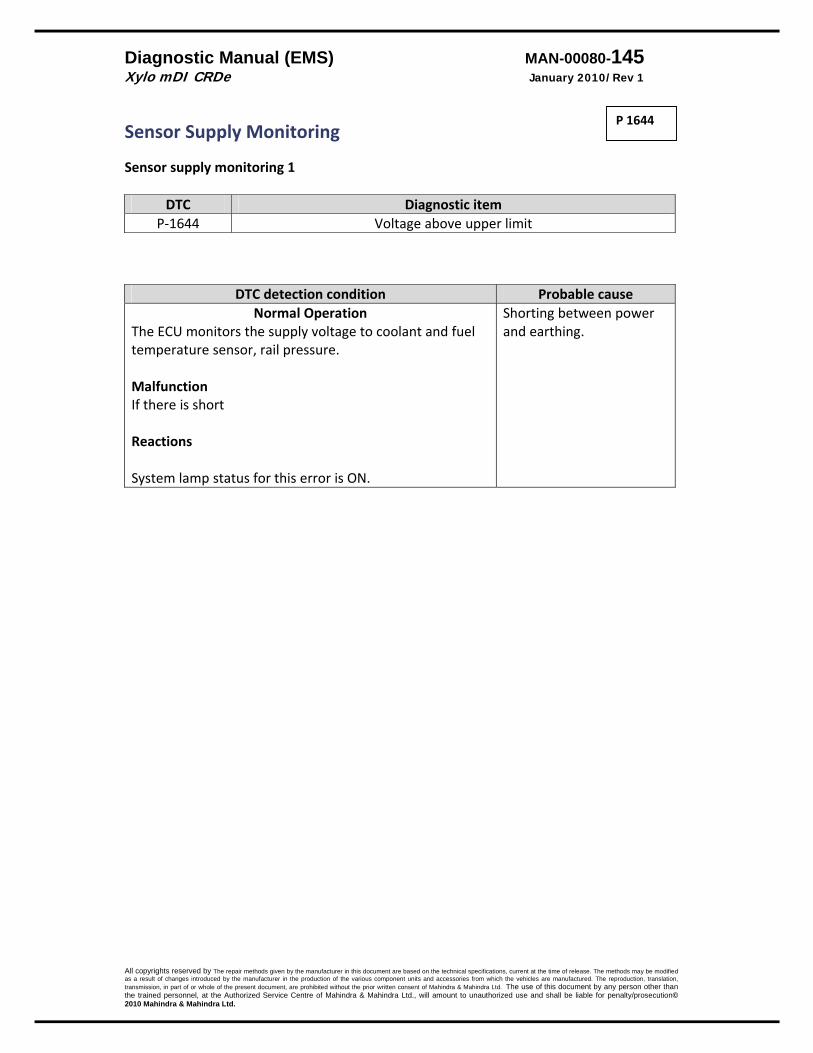
Diagnostic Manual (EMS) MAN-00080-145 Xylo mDI CRDe January 2010/Rev 1
All copyrights reserved by The repair methods given by the manufacturer in this document are based on the technical specifications, current at the time of release. The methods may be modified as a result of changes introduced by the manufacturer in the production of the various component units and accessories from which the vehicles are manufactured. The reproduction, translation, transmission, in part of or whole of the present document, are prohibited without the prior written consent of Mahindra & Mahindra Ltd. The use of this document by any person other than the trained personnel, at the Authorized Service Centre of Mahindra & Mahindra Ltd., will amount to unauthorized use and shall be liable for penalty/prosecution© 2010 Mahindra & Mahindra Ltd.
Sensor Supply Monitoring Sensor supply monitoring 1
DTC Diagnostic item P‐1644 Voltage above upper limit
DTC detection condition Probable cause Normal Operation
The ECU monitors the supply voltage to coolant and fuel temperature sensor, rail pressure. Malfunction If there is short Reactions System lamp status for this error is ON.
Shorting between power and earthing.
P 1644
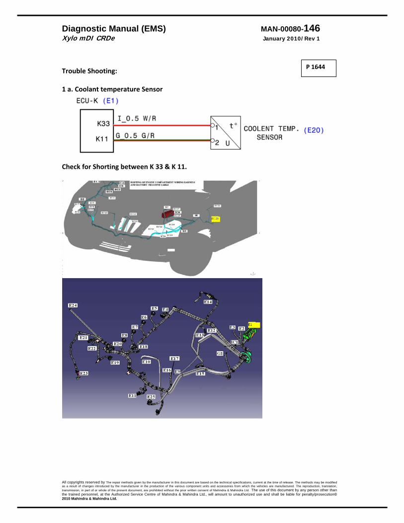
Diagnostic Manual (EMS) MAN-00080-146 Xylo mDI CRDe January 2010/Rev 1
All copyrights reserved by The repair methods given by the manufacturer in this document are based on the technical specifications, current at the time of release. The methods may be modified as a result of changes introduced by the manufacturer in the production of the various component units and accessories from which the vehicles are manufactured. The reproduction, translation, transmission, in part of or whole of the present document, are prohibited without the prior written consent of Mahindra & Mahindra Ltd. The use of this document by any person other than the trained personnel, at the Authorized Service Centre of Mahindra & Mahindra Ltd., will amount to unauthorized use and shall be liable for penalty/prosecution© 2010 Mahindra & Mahindra Ltd.
Trouble Shooting: 1 a. Coolant temperature Sensor
Check for Shorting between K 33 & K 11.
P 1644
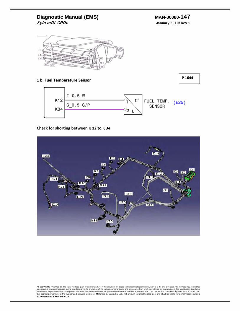
Diagnostic Manual (EMS) MAN-00080-147 Xylo mDI CRDe January 2010/Rev 1
All copyrights reserved by The repair methods given by the manufacturer in this document are based on the technical specifications, current at the time of release. The methods may be modified as a result of changes introduced by the manufacturer in the production of the various component units and accessories from which the vehicles are manufactured. The reproduction, translation, transmission, in part of or whole of the present document, are prohibited without the prior written consent of Mahindra & Mahindra Ltd. The use of this document by any person other than the trained personnel, at the Authorized Service Centre of Mahindra & Mahindra Ltd., will amount to unauthorized use and shall be liable for penalty/prosecution© 2010 Mahindra & Mahindra Ltd.
1 b. Fuel Temperature Sensor
Check for shorting between K 12 to K 34
P 1644

Diagnostic Manual (EMS) MAN-00080-148 Xylo mDI CRDe January 2010/Rev 1
All copyrights reserved by The repair methods given by the manufacturer in this document are based on the technical specifications, current at the time of release. The methods may be modified as a result of changes introduced by the manufacturer in the production of the various component units and accessories from which the vehicles are manufactured. The reproduction, translation, transmission, in part of or whole of the present document, are prohibited without the prior written consent of Mahindra & Mahindra Ltd. The use of this document by any person other than the trained personnel, at the Authorized Service Centre of Mahindra & Mahindra Ltd., will amount to unauthorized use and shall be liable for penalty/prosecution© 2010 Mahindra & Mahindra Ltd.
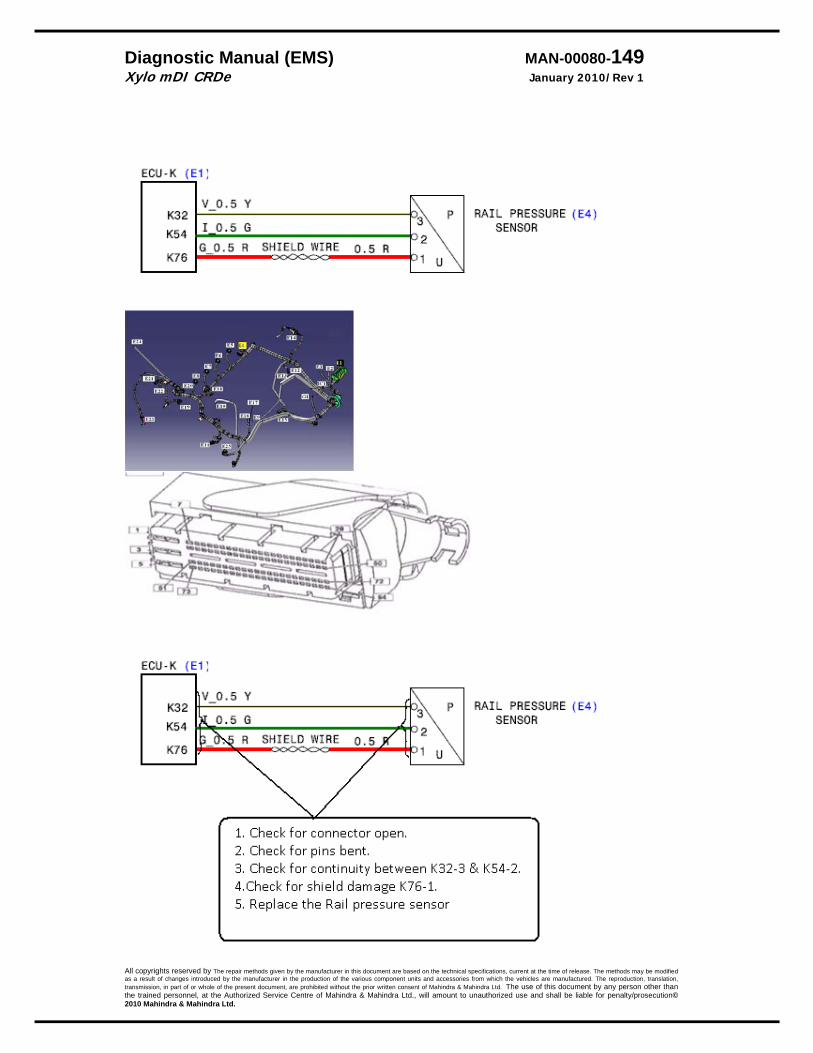
Diagnostic Manual (EMS) MAN-00080-149 Xylo mDI CRDe January 2010/Rev 1
All copyrights reserved by The repair methods given by the manufacturer in this document are based on the technical specifications, current at the time of release. The methods may be modified as a result of changes introduced by the manufacturer in the production of the various component units and accessories from which the vehicles are manufactured. The reproduction, translation, transmission, in part of or whole of the present document, are prohibited without the prior written consent of Mahindra & Mahindra Ltd. The use of this document by any person other than the trained personnel, at the Authorized Service Centre of Mahindra & Mahindra Ltd., will amount to unauthorized use and shall be liable for penalty/prosecution© 2010 Mahindra & Mahindra Ltd.

Diagnostic Manual (EMS) MAN-00080-150 Xylo mDI CRDe January 2010/Rev 1
All copyrights reserved by The repair methods given by the manufacturer in this document are based on the technical specifications, current at the time of release. The methods may be modified as a result of changes introduced by the manufacturer in the production of the various component units and accessories from which the vehicles are manufactured. The reproduction, translation, transmission, in part of or whole of the present document, are prohibited without the prior written consent of Mahindra & Mahindra Ltd. The use of this document by any person other than the trained personnel, at the Authorized Service Centre of Mahindra & Mahindra Ltd., will amount to unauthorized use and shall be liable for penalty/prosecution© 2010 Mahindra & Mahindra Ltd.
Note: the rail pressure sensor should be changed along with the rail only. Changing only the rail pressure sensor is not recommended.
1. If any wiring is found short then correct / replace the wiring
2. After correcting‐ clear the error code and then confirm if the complaint is still present.
3. If yes, then replace the EMS ECU. Before sending that send the CrFr and take the tekhub/tekliner approval. ( In any case if the ECU is being replaced‐ replace the wiring – even if no visible short to battery or ground is visible.)
P 1644

Diagnostic Manual (EMS) MAN-00080-151 Xylo mDI CRDe January 2010/Rev 1
All copyrights reserved by The repair methods given by the manufacturer in this document are based on the technical specifications, current at the time of release. The methods may be modified as a result of changes introduced by the manufacturer in the production of the various component units and accessories from which the vehicles are manufactured. The reproduction, translation, transmission, in part of or whole of the present document, are prohibited without the prior written consent of Mahindra & Mahindra Ltd. The use of this document by any person other than the trained personnel, at the Authorized Service Centre of Mahindra & Mahindra Ltd., will amount to unauthorized use and shall be liable for penalty/prosecution© 2010 Mahindra & Mahindra Ltd.
Sensor Supply Monitoring Sensor supply monitoring 2
DTC Diagnostic item P‐1646 Error is sensor supply Monitor 2
DTC detection condition Probable cause Normal Operation
The Sensor supplier monitor 2 monitors the supply to APP 2 Malfunction If the monitored voltage is outside the limits then this fault is registered Reactions Check lamp is ON. Vehicle in limp home @ 1200 RPM
Supply wire short to battery.
P 1646
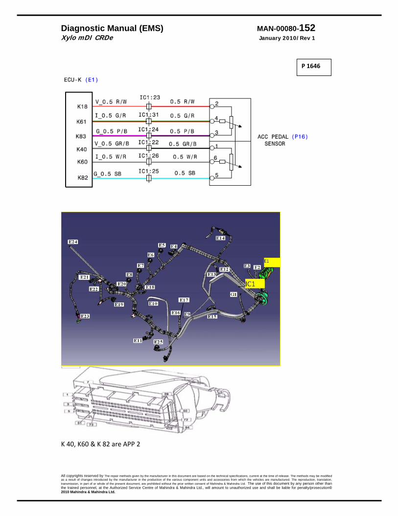
Diagnostic Manual (EMS) MAN-00080-152 Xylo mDI CRDe January 2010/Rev 1
All copyrights reserved by The repair methods given by the manufacturer in this document are based on the technical specifications, current at the time of release. The methods may be modified as a result of changes introduced by the manufacturer in the production of the various component units and accessories from which the vehicles are manufactured. The reproduction, translation, transmission, in part of or whole of the present document, are prohibited without the prior written consent of Mahindra & Mahindra Ltd. The use of this document by any person other than the trained personnel, at the Authorized Service Centre of Mahindra & Mahindra Ltd., will amount to unauthorized use and shall be liable for penalty/prosecution© 2010 Mahindra & Mahindra Ltd.
K 40, K60 & K 82 are APP 2
P 1646
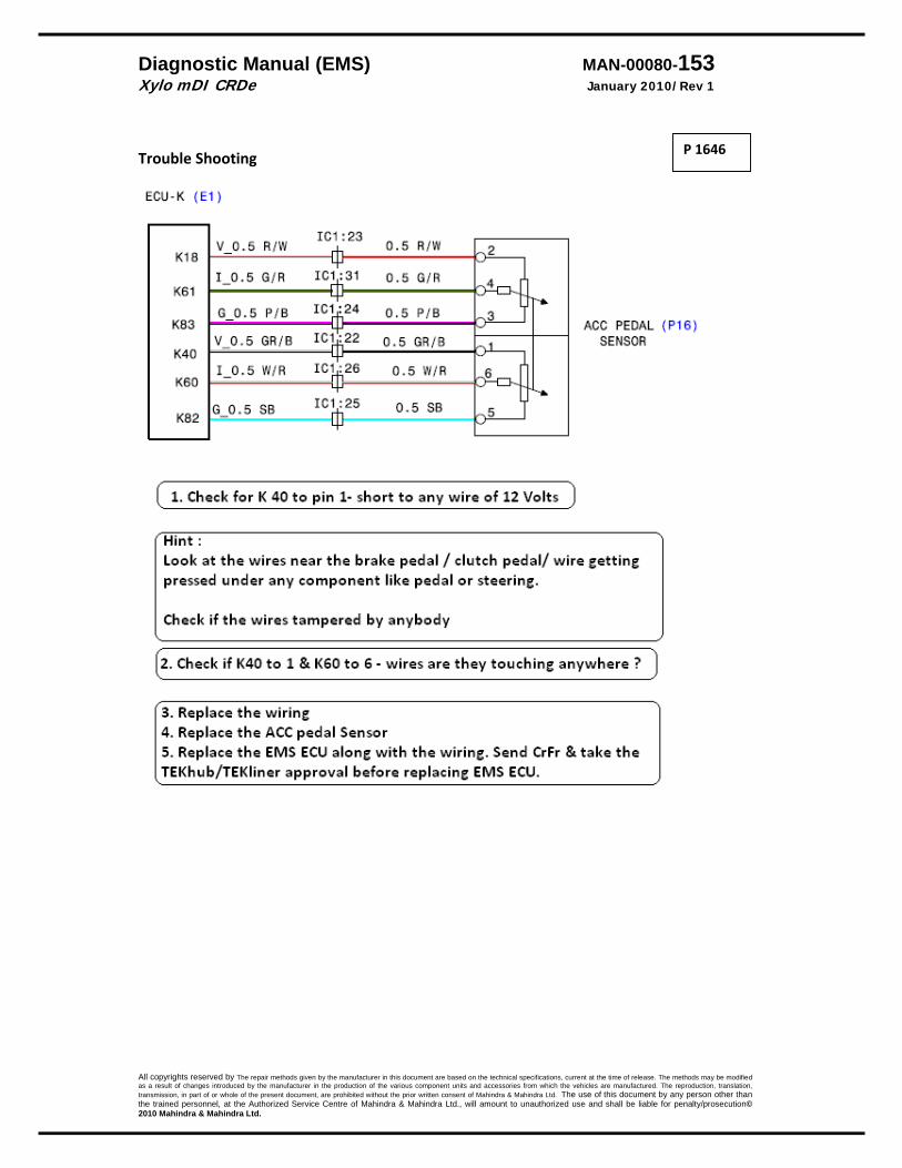
Diagnostic Manual (EMS) MAN-00080-153 Xylo mDI CRDe January 2010/Rev 1
All copyrights reserved by The repair methods given by the manufacturer in this document are based on the technical specifications, current at the time of release. The methods may be modified as a result of changes introduced by the manufacturer in the production of the various component units and accessories from which the vehicles are manufactured. The reproduction, translation, transmission, in part of or whole of the present document, are prohibited without the prior written consent of Mahindra & Mahindra Ltd. The use of this document by any person other than the trained personnel, at the Authorized Service Centre of Mahindra & Mahindra Ltd., will amount to unauthorized use and shall be liable for penalty/prosecution© 2010 Mahindra & Mahindra Ltd.
Trouble Shooting
P 1646
Diagnostic Manual (EMS) MAN-00080-154 Xylo mDI CRDe January 2010/Rev 1
All copyrights reserved by The repair methods given by the manufacturer in this document are based on the technical specifications, current at the time of release. The methods may be modified as a result of changes introduced by the manufacturer in the production of the various component units and accessories from which the vehicles are manufactured. The reproduction, translation, transmission, in part of or whole of the present document, are prohibited without the prior written consent of Mahindra & Mahindra Ltd. The use of this document by any person other than the trained personnel, at the Authorized Service Centre of Mahindra & Mahindra Ltd., will amount to unauthorized use and shall be liable for penalty/prosecution© 2010 Mahindra & Mahindra Ltd.
Sensor Supply Monitoring Sensor supply monitoring 3
DTC Diagnostic item P‐1648 Error is sensor supply Monitor 3
DTC detection condition Probable cause Normal Operation
The Sensor supplier monitor 2 monitors the supply to APP 1 Malfunction If the monitored voltage is outside the limits then this fault is registered Reactions Check lamp is ON. Vehicle in limp home@ 1200 RPM
Supply wire short to battery.
P 1648

Diagnostic Manual (EMS) MAN-00080-155 Xylo mDI CRDe January 2010/Rev 1
All copyrights reserved by The repair methods given by the manufacturer in this document are based on the technical specifications, current at the time of release. The methods may be modified as a result of changes introduced by the manufacturer in the production of the various component units and accessories from which the vehicles are manufactured. The reproduction, translation, transmission, in part of or whole of the present document, are prohibited without the prior written consent of Mahindra & Mahindra Ltd. The use of this document by any person other than the trained personnel, at the Authorized Service Centre of Mahindra & Mahindra Ltd., will amount to unauthorized use and shall be liable for penalty/prosecution© 2010 Mahindra & Mahindra Ltd.
K 40, K60 & K 82 are APP 2
P 1648
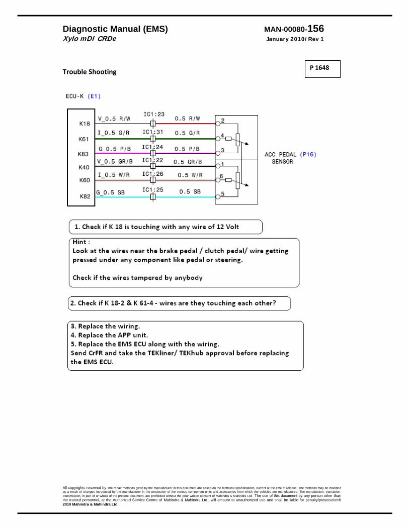
Diagnostic Manual (EMS) MAN-00080-156 Xylo mDI CRDe January 2010/Rev 1
All copyrights reserved by The repair methods given by the manufacturer in this document are based on the technical specifications, current at the time of release. The methods may be modified as a result of changes introduced by the manufacturer in the production of the various component units and accessories from which the vehicles are manufactured. The reproduction, translation, transmission, in part of or whole of the present document, are prohibited without the prior written consent of Mahindra & Mahindra Ltd. The use of this document by any person other than the trained personnel, at the Authorized Service Centre of Mahindra & Mahindra Ltd., will amount to unauthorized use and shall be liable for penalty/prosecution© 2010 Mahindra & Mahindra Ltd.
Trouble Shooting
P 1648

Diagnostic Manual (EMS) MAN-00080-157 Xylo mDI CRDe January 2010/Rev 1
All copyrights reserved by The repair methods given by the manufacturer in this document are based on the technical specifications, current at the time of release. The methods may be modified as a result of changes introduced by the manufacturer in the production of the various component units and accessories from which the vehicles are manufactured. The reproduction, translation, transmission, in part of or whole of the present document, are prohibited without the prior written consent of Mahindra & Mahindra Ltd. The use of this document by any person other than the trained personnel, at the Authorized Service Centre of Mahindra & Mahindra Ltd., will amount to unauthorized use and shall be liable for penalty/prosecution© 2010 Mahindra & Mahindra Ltd.
Continous Torque Monitoring
DTC Diagnostic item P1900 NTP error in ADC monitoring P1901 Sensor supply error for APP P1902 Error in plausibility of the test voltage in ADC monitoring P1903 Error in plausibility of the ratiometry correction in ADC monitoring
DTC Monitored Component P1900 The ADC ( Analog to Digital Controller ) of the micro controller is
monitored P1901 The ADC ( Analog to Digital Controller ) of the micro controller is
monitored This error is registered when the Sensor supply monitoring operation notes an error in sensor supply for the APP
P1902 The ADC ( Analog to Digital Controller ) of the micro controller is monitored Malfunction If the test voltage converted by the ADC does not lie within the limit then it is registered as an error.
P1903 The ADC ( Analog to Digital Controller ) of the micro controller is monitored Malfunction If the ratiometry correction is not plausible then this error is set.
Reaction: Check lamp is ON Engine OFF.
Probable Cause Corrective Action ECU failure 1. Clear the error.
2. IS the error still present 3. If yes, try for at least 3 times. 4. Change the EMS ECU. Submit CrFr and take the TEKhub
approval.
P1900 P1901 P1902 P1903
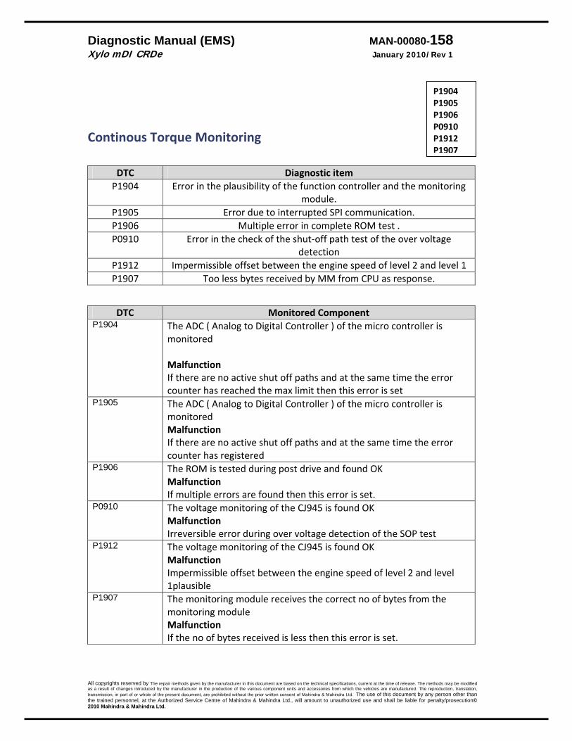
Diagnostic Manual (EMS) MAN-00080-158 Xylo mDI CRDe January 2010/Rev 1
All copyrights reserved by The repair methods given by the manufacturer in this document are based on the technical specifications, current at the time of release. The methods may be modified as a result of changes introduced by the manufacturer in the production of the various component units and accessories from which the vehicles are manufactured. The reproduction, translation, transmission, in part of or whole of the present document, are prohibited without the prior written consent of Mahindra & Mahindra Ltd. The use of this document by any person other than the trained personnel, at the Authorized Service Centre of Mahindra & Mahindra Ltd., will amount to unauthorized use and shall be liable for penalty/prosecution© 2010 Mahindra & Mahindra Ltd.
Continous Torque Monitoring
DTC Diagnostic itemP1904 Error in the plausibility of the function controller and the monitoring
module. P1905 Error due to interrupted SPI communication. P1906 Multiple error in complete ROM test .P0910 Error in the check of the shut‐off path test of the over voltage
detection P1912 Impermissible offset between the engine speed of level 2 and level 1 P1907 Too less bytes received by MM from CPU as response.
DTC Monitored Component P1904 The ADC ( Analog to Digital Controller ) of the micro controller is
monitored Malfunction If there are no active shut off paths and at the same time the error counter has reached the max limit then this error is set
P1905 The ADC ( Analog to Digital Controller ) of the micro controller is monitored Malfunction If there are no active shut off paths and at the same time the error counter has registered
P1906 The ROM is tested during post drive and found OK Malfunction If multiple errors are found then this error is set.
P0910 The voltage monitoring of the CJ945 is found OKMalfunction Irreversible error during over voltage detection of the SOP test
P1912 The voltage monitoring of the CJ945 is found OKMalfunction Impermissible offset between the engine speed of level 2 and level 1plausible
P1907 The monitoring module receives the correct no of bytes from the monitoring module Malfunction If the no of bytes received is less then this error is set.
P1904 P1905 P1906 P0910 P1912 P1907
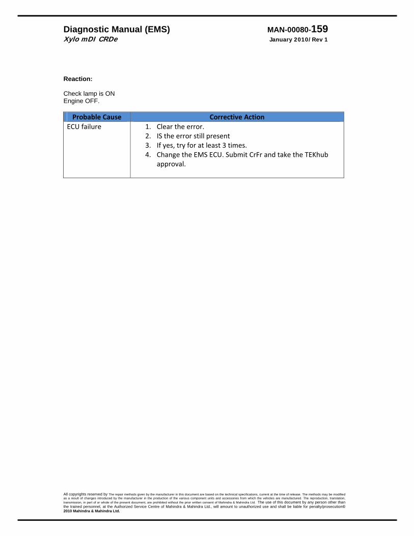
Diagnostic Manual (EMS) MAN-00080-159 Xylo mDI CRDe January 2010/Rev 1
All copyrights reserved by The repair methods given by the manufacturer in this document are based on the technical specifications, current at the time of release. The methods may be modified as a result of changes introduced by the manufacturer in the production of the various component units and accessories from which the vehicles are manufactured. The reproduction, translation, transmission, in part of or whole of the present document, are prohibited without the prior written consent of Mahindra & Mahindra Ltd. The use of this document by any person other than the trained personnel, at the Authorized Service Centre of Mahindra & Mahindra Ltd., will amount to unauthorized use and shall be liable for penalty/prosecution© 2010 Mahindra & Mahindra Ltd.
Reaction: Check lamp is ON Engine OFF.
Probable Cause Corrective Action ECU failure 1. Clear the error.
2. IS the error still present 3. If yes, try for at least 3 times. 4. Change the EMS ECU. Submit CrFr and take the TEKhub
approval.
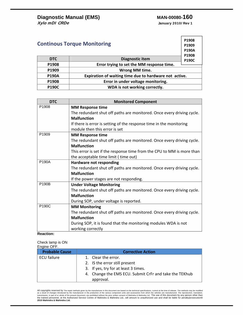
Diagnostic Manual (EMS) MAN-00080-160 Xylo mDI CRDe January 2010/Rev 1
All copyrights reserved by The repair methods given by the manufacturer in this document are based on the technical specifications, current at the time of release. The methods may be modified as a result of changes introduced by the manufacturer in the production of the various component units and accessories from which the vehicles are manufactured. The reproduction, translation, transmission, in part of or whole of the present document, are prohibited without the prior written consent of Mahindra & Mahindra Ltd. The use of this document by any person other than the trained personnel, at the Authorized Service Centre of Mahindra & Mahindra Ltd., will amount to unauthorized use and shall be liable for penalty/prosecution© 2010 Mahindra & Mahindra Ltd.
Continous Torque Monitoring
DTC Diagnostic item P1908 Error trying to set the MM response time. P1909 Wrong MM time. P190A Expiration of waiting time due to hardware not active. P190B Error in under voltage monitoring.P190C WDA is not working correctly.
DTC Monitored ComponentP1908 MM Response time
The redundant shut off paths are monitored. Once every driving cycle.Malfunction If there is error is setting of the response time in the monitoring module then this error is set
P1909 MM Response time The redundant shut off paths are monitored. Once every driving cycle.Malfunction This error is set if the response time from the CPU to MM is more than the acceptable time limit ( time out)
P190A Hardware not responding The redundant shut off paths are monitored. Once every driving cycle. Malfunction If the power stages are not responding.
P190B Under Voltage Monitoring The redundant shut off paths are monitored. Once every driving cycle. Malfunction During SOP, under voltage is reported.
P190C MM MonitoringThe redundant shut off paths are monitored. Once every driving cycle. Malfunction During SOP, it is found that the monitoring modules WDA is not working correctly
Reaction: Check lamp is ON Engine OFF.
Probable Cause Corrective Action ECU failure 1. Clear the error.
2. IS the error still present 3. If yes, try for at least 3 times. 4. Change the EMS ECU. Submit CrFr and take the TEKhub
approval.
P1908 P1909 P190A P190B P190C
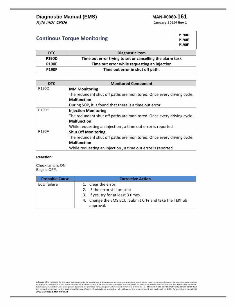
Diagnostic Manual (EMS) MAN-00080-161 Xylo mDI CRDe January 2010/Rev 1
All copyrights reserved by The repair methods given by the manufacturer in this document are based on the technical specifications, current at the time of release. The methods may be modified as a result of changes introduced by the manufacturer in the production of the various component units and accessories from which the vehicles are manufactured. The reproduction, translation, transmission, in part of or whole of the present document, are prohibited without the prior written consent of Mahindra & Mahindra Ltd. The use of this document by any person other than the trained personnel, at the Authorized Service Centre of Mahindra & Mahindra Ltd., will amount to unauthorized use and shall be liable for penalty/prosecution© 2010 Mahindra & Mahindra Ltd.
Continous Torque Monitoring
DTC Diagnostic itemP190D Time out error trying to set or cancelling the alarm task P190E Time out error while requesting an injection P190F Time out error in shut off path.
DTC Monitored ComponentP190D MM Monitoring
The redundant shut off paths are monitored. Once every driving cycle. Malfunction During SOP, it is found that there is a time out error
P190E Injection MonitoringThe redundant shut off paths are monitored. Once every driving cycle. Malfunction While requesting an injection , a time out error is reported
P190F Shut Off Monitoring The redundant shut off paths are monitored. Once every driving cycle. Malfunction While requesting an injection , a time out error is reported
Reaction: Check lamp is ON Engine OFF.
Probable Cause Corrective Action ECU failure 1. Clear the error.
2. IS the error still present 3. If yes, try for at least 3 times. 4. Change the EMS ECU. Submit CrFr and take the TEKhub
approval.
P190D P190E P190F
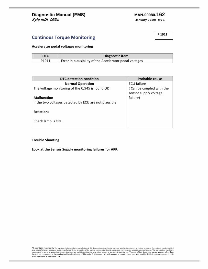
Diagnostic Manual (EMS) MAN-00080-162 Xylo mDI CRDe January 2010/Rev 1
All copyrights reserved by The repair methods given by the manufacturer in this document are based on the technical specifications, current at the time of release. The methods may be modified as a result of changes introduced by the manufacturer in the production of the various component units and accessories from which the vehicles are manufactured. The reproduction, translation, transmission, in part of or whole of the present document, are prohibited without the prior written consent of Mahindra & Mahindra Ltd. The use of this document by any person other than the trained personnel, at the Authorized Service Centre of Mahindra & Mahindra Ltd., will amount to unauthorized use and shall be liable for penalty/prosecution© 2010 Mahindra & Mahindra Ltd.
Continous Torque Monitoring Accelerator pedal voltages monitoring
DTC Diagnostic itemP1911 Error in plausibility of the Accelerator pedal voltages
DTC detection condition Probable cause Normal Operation
The voltage monitoring of the CJ945 is found OK Malfunction If the two voltages detected by ECU are not plausible Reactions Check lamp is ON.
ECU failure ( Can be coupled with the sensor supply voltage failure)
Trouble Shooting Look at the Sensor Supply monitoring failures for APP.
P 1911

Diagnostic Manual (EMS) MAN-00080-163 Xylo mDI CRDe January 2010/Rev 1
All copyrights reserved by The repair methods given by the manufacturer in this document are based on the technical specifications, current at the time of release. The methods may be modified as a result of changes introduced by the manufacturer in the production of the various component units and accessories from which the vehicles are manufactured. The reproduction, translation, transmission, in part of or whole of the present document, are prohibited without the prior written consent of Mahindra & Mahindra Ltd. The use of this document by any person other than the trained personnel, at the Authorized Service Centre of Mahindra & Mahindra Ltd., will amount to unauthorized use and shall be liable for penalty/prosecution© 2010 Mahindra & Mahindra Ltd.
Continous Torque Monitoring ET plausibility check
DTC Diagnostic itemP1913 ET plausibility check failure
DTC detection condition Probable cause Normal Operation
The voltage monitoring of the CJ945 is found OK Malfunction If the difference between the programmed energizing time and the measured energizing time exceeds a limit then this error will be registerd Reactions Check lamp is ON. Engine switches OFF
1. Wiring from ECU to injector changed.
2. Wrong dataset. 3. ECU failure.
Trouble Shooting
1. Check the wires from the injector to ECU for any fitment ? Change the wiring if suspect.
2.Check the dataset‐ reflash the correct dataset. 3. Change the EMS ECU‐ take the TEKliner/ TEKhub approval before replacing . A CrFr is compulsory.
P 1913

Diagnostic Manual (EMS) MAN-00080-164 Xylo mDI CRDe January 2010/Rev 1
All copyrights reserved by The repair methods given by the manufacturer in this document are based on the technical specifications, current at the time of release. The methods may be modified as a result of changes introduced by the manufacturer in the production of the various component units and accessories from which the vehicles are manufactured. The reproduction, translation, transmission, in part of or whole of the present document, are prohibited without the prior written consent of Mahindra & Mahindra Ltd. The use of this document by any person other than the trained personnel, at the Authorized Service Centre of Mahindra & Mahindra Ltd., will amount to unauthorized use and shall be liable for penalty/prosecution© 2010 Mahindra & Mahindra Ltd.
Continous Torque Monitoring ET plausibility check
DTC Diagnostic itemP1914 Error in the plausibility of the start of energising angles
DTC detection condition Probable cause Normal Operation
The start of the energizing time is monitored Malfunction If the start of the energizing time is outside the plausible valid range then this error is registered Reactions Check lamp is ON. Engine switches OFF
1. Wiring from ECU to injector changed.
2. Wrong dataset. 3. EMI interference in
the signal from the Engine speed sensor ( look at the starter motor cable & starter motor condition.)
4. ECU failure. Trouble Shooting
1. Check the wires from the injector to ECU for any fitment ? Change the wiring if suspect.
2.Check the dataset‐ reflash the correct dataset. 3. Look for possible EMI interference in signal from the Engine sensor ( possible cause can be starter motor cable or starter motor taking extra load )
4. Change the EMS ECU‐ take the TEKliner/ TEKhub approval before replacing . A CrFr is compulsory.
P 1914
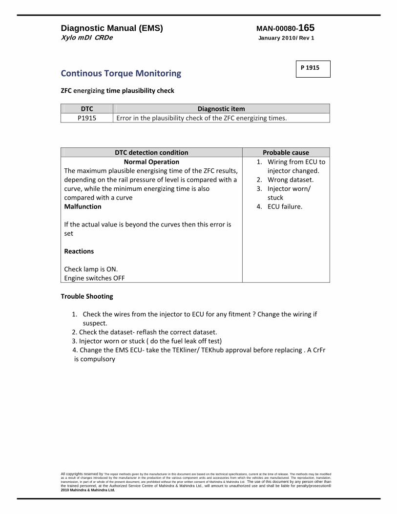
Diagnostic Manual (EMS) MAN-00080-165 Xylo mDI CRDe January 2010/Rev 1
All copyrights reserved by The repair methods given by the manufacturer in this document are based on the technical specifications, current at the time of release. The methods may be modified as a result of changes introduced by the manufacturer in the production of the various component units and accessories from which the vehicles are manufactured. The reproduction, translation, transmission, in part of or whole of the present document, are prohibited without the prior written consent of Mahindra & Mahindra Ltd. The use of this document by any person other than the trained personnel, at the Authorized Service Centre of Mahindra & Mahindra Ltd., will amount to unauthorized use and shall be liable for penalty/prosecution© 2010 Mahindra & Mahindra Ltd.
Continous Torque Monitoring ZFC energizing time plausibility check
DTC Diagnostic itemP1915 Error in the plausibility check of the ZFC energizing times.
DTC detection condition Probable cause Normal Operation
The maximum plausible energising time of the ZFC results, depending on the rail pressure of level is compared with a curve, while the minimum energizing time is also compared with a curve Malfunction If the actual value is beyond the curves then this error is set Reactions Check lamp is ON. Engine switches OFF
1. Wiring from ECU to injector changed.
2. Wrong dataset. 3. Injector worn/
stuck 4. ECU failure.
Trouble Shooting
1. Check the wires from the injector to ECU for any fitment ? Change the wiring if suspect.
2. Check the dataset‐ reflash the correct dataset. 3. Injector worn or stuck ( do the fuel leak off test)
4. Change the EMS ECU‐ take the TEKliner/ TEKhub approval before replacing . A CrFr is compulsory
P 1915
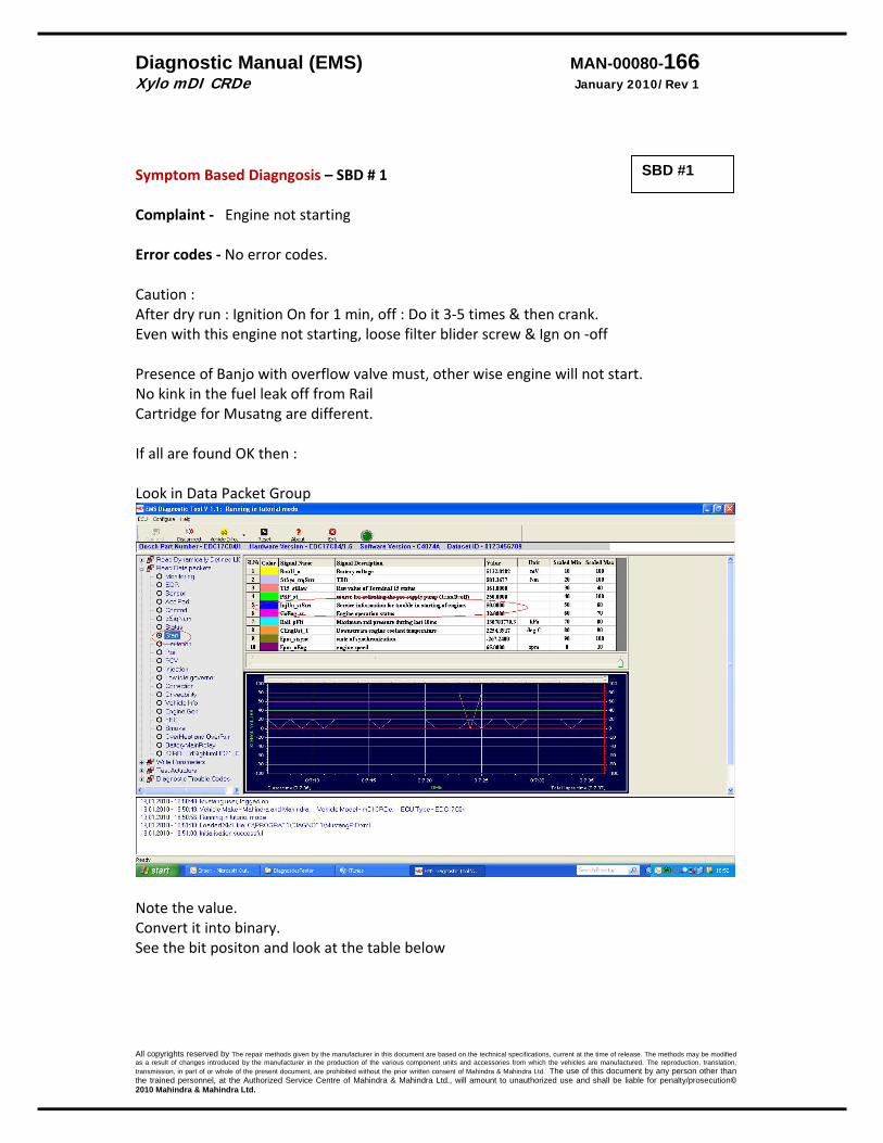
Diagnostic Manual (EMS) MAN-00080-166 Xylo mDI CRDe January 2010/Rev 1
All copyrights reserved by The repair methods given by the manufacturer in this document are based on the technical specifications, current at the time of release. The methods may be modified as a result of changes introduced by the manufacturer in the production of the various component units and accessories from which the vehicles are manufactured. The reproduction, translation, transmission, in part of or whole of the present document, are prohibited without the prior written consent of Mahindra & Mahindra Ltd. The use of this document by any person other than the trained personnel, at the Authorized Service Centre of Mahindra & Mahindra Ltd., will amount to unauthorized use and shall be liable for penalty/prosecution© 2010 Mahindra & Mahindra Ltd.
Symptom Based Diagngosis – SBD # 1 Complaint ‐ Engine not starting Error codes ‐ No error codes. Caution : After dry run : Ignition On for 1 min, off : Do it 3‐5 times & then crank. Even with this engine not starting, loose filter blider screw & Ign on ‐off Presence of Banjo with overflow valve must, other wise engine will not start. No kink in the fuel leak off from Rail Cartridge for Musatng are different. If all are found OK then : Look in Data Packet Group
Note the value. Convert it into binary. See the bit positon and look at the table below
SBD #1
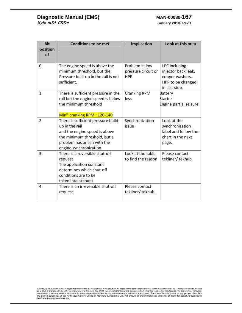
Diagnostic Manual (EMS) MAN-00080-167 Xylo mDI CRDe January 2010/Rev 1
All copyrights reserved by The repair methods given by the manufacturer in this document are based on the technical specifications, current at the time of release. The methods may be modified as a result of changes introduced by the manufacturer in the production of the various component units and accessories from which the vehicles are manufactured. The reproduction, translation, transmission, in part of or whole of the present document, are prohibited without the prior written consent of Mahindra & Mahindra Ltd. The use of this document by any person other than the trained personnel, at the Authorized Service Centre of Mahindra & Mahindra Ltd., will amount to unauthorized use and shall be liable for penalty/prosecution© 2010 Mahindra & Mahindra Ltd.
Bit
position of
Conditions to be met
Implication Look at this area
0 The engine speed is above the minimum threshold, but the Pressure built up in the rail is not sufficient.
Problem in low pressure circuit or HPP
LPC including injector back leak, copper washers. HPP to be changed in last step.
1 There is sufficient pressure in the rail but the engine speed is below the minimum threshold Minm cranking RPM : 120‐140
Cranking RPM less
Battery Starter Engine partial seizure
2 There is sufficient pressure build‐up in the rail and the engine speed is above the minimum threshold, but a problem has arisen with the engine synchronization
Synchronization issue
Look at the synchronization label and follow the chart in the next page.
3 There is a reversible shut‐off request The application constant determines which shut‐off conditions are to be taken into account.
Look at the table to find the reason
Please contact tekliner/ tekhub.
4 There is an irreversible shut‐off request
Please contact tekliner/ tekhub.
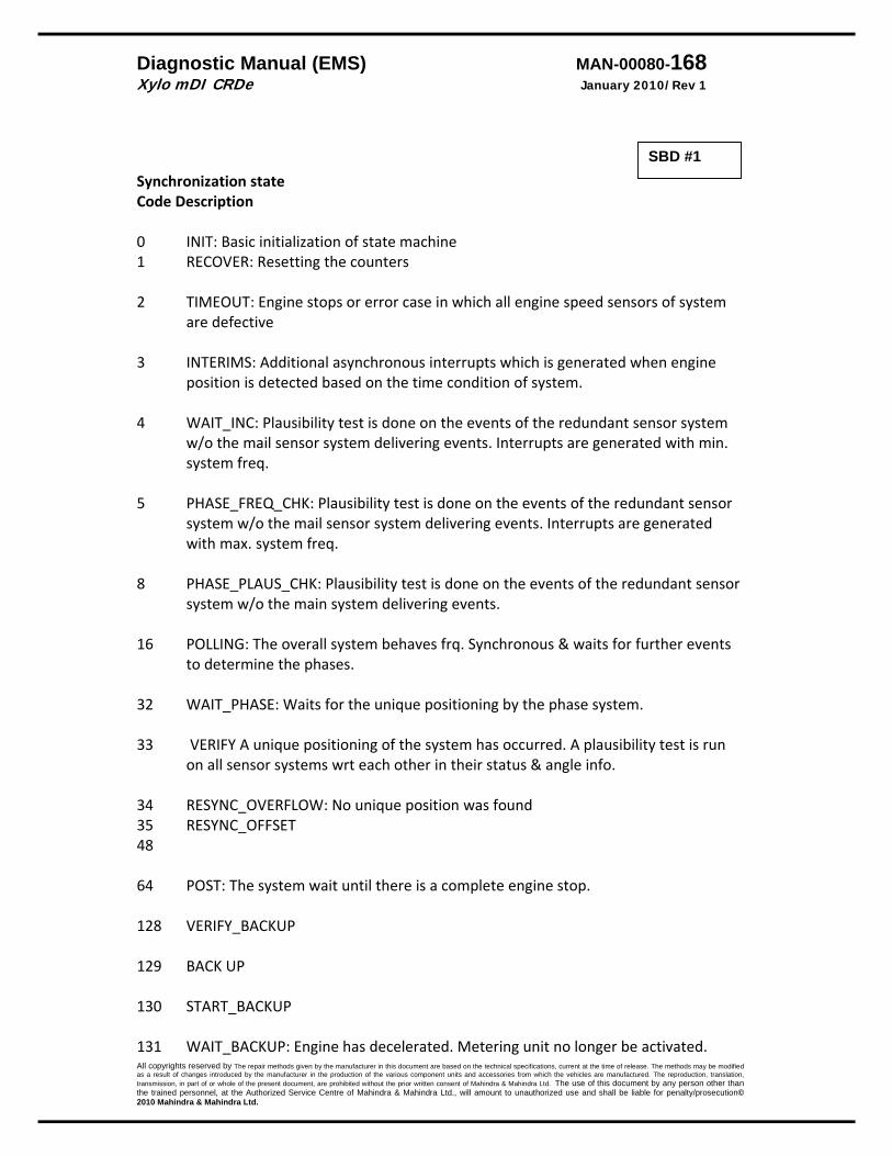
Diagnostic Manual (EMS) MAN-00080-168 Xylo mDI CRDe January 2010/Rev 1
All copyrights reserved by The repair methods given by the manufacturer in this document are based on the technical specifications, current at the time of release. The methods may be modified as a result of changes introduced by the manufacturer in the production of the various component units and accessories from which the vehicles are manufactured. The reproduction, translation, transmission, in part of or whole of the present document, are prohibited without the prior written consent of Mahindra & Mahindra Ltd. The use of this document by any person other than the trained personnel, at the Authorized Service Centre of Mahindra & Mahindra Ltd., will amount to unauthorized use and shall be liable for penalty/prosecution© 2010 Mahindra & Mahindra Ltd.
Synchronization state Code Description 0 INIT: Basic initialization of state machine 1 RECOVER: Resetting the counters 2 TIMEOUT: Engine stops or error case in which all engine speed sensors of system
are defective 3 INTERIMS: Additional asynchronous interrupts which is generated when engine
position is detected based on the time condition of system. 4 WAIT_INC: Plausibility test is done on the events of the redundant sensor system
w/o the mail sensor system delivering events. Interrupts are generated with min. system freq.
5 PHASE_FREQ_CHK: Plausibility test is done on the events of the redundant sensor
system w/o the mail sensor system delivering events. Interrupts are generated with max. system freq.
8 PHASE_PLAUS_CHK: Plausibility test is done on the events of the redundant sensor
system w/o the main system delivering events. 16 POLLING: The overall system behaves frq. Synchronous & waits for further events
to determine the phases. 32 WAIT_PHASE: Waits for the unique positioning by the phase system. 33 VERIFY A unique positioning of the system has occurred. A plausibility test is run
on all sensor systems wrt each other in their status & angle info. 34 RESYNC_OVERFLOW: No unique position was found 35 RESYNC_OFFSET 48 64 POST: The system wait until there is a complete engine stop. 128 VERIFY_BACKUP 129 BACK UP 130 START_BACKUP 131 WAIT_BACKUP: Engine has decelerated. Metering unit no longer be activated.
SBD #1
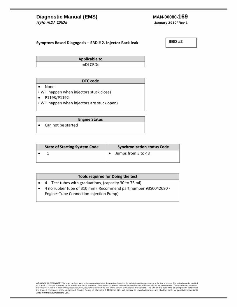
Diagnostic Manual (EMS) MAN-00080-169 Xylo mDI CRDe January 2010/Rev 1
All copyrights reserved by The repair methods given by the manufacturer in this document are based on the technical specifications, current at the time of release. The methods may be modified as a result of changes introduced by the manufacturer in the production of the various component units and accessories from which the vehicles are manufactured. The reproduction, translation, transmission, in part of or whole of the present document, are prohibited without the prior written consent of Mahindra & Mahindra Ltd. The use of this document by any person other than the trained personnel, at the Authorized Service Centre of Mahindra & Mahindra Ltd., will amount to unauthorized use and shall be liable for penalty/prosecution© 2010 Mahindra & Mahindra Ltd.
Symptom Based Diagngosis – SBD # 2. Injector Back leak
Applicable to mDI CRDe
DTC code• None ( Will happen when injectors stuck close) • P1193/P1192 ( Will happen when injectors are stuck open)
Engine Status• Can not be started
State of Starting System Code Synchronization status Code
• 1
• Jumps from 3 to 48
Tools required for Doing the test
• 4 Test tubes with graduations, (capacity 30 to 75 ml) • 4 no rubber tube of 310 mm ( Recommend part number 9350042680 ‐
Engine–Tube Connection Injection Pump)
SBD #2
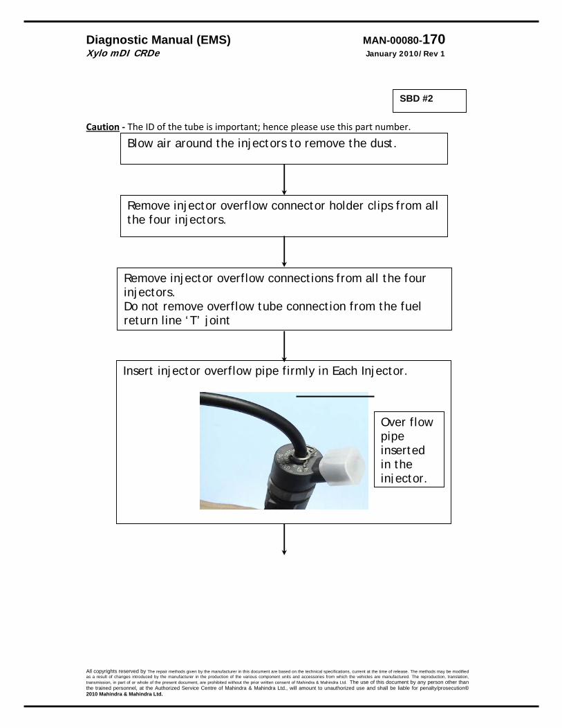
Diagnostic Manual (EMS) MAN-00080-170 Xylo mDI CRDe January 2010/Rev 1
All copyrights reserved by The repair methods given by the manufacturer in this document are based on the technical specifications, current at the time of release. The methods may be modified as a result of changes introduced by the manufacturer in the production of the various component units and accessories from which the vehicles are manufactured. The reproduction, translation, transmission, in part of or whole of the present document, are prohibited without the prior written consent of Mahindra & Mahindra Ltd. The use of this document by any person other than the trained personnel, at the Authorized Service Centre of Mahindra & Mahindra Ltd., will amount to unauthorized use and shall be liable for penalty/prosecution© 2010 Mahindra & Mahindra Ltd.
Caution ‐ The ID of the tube is important; hence please use this part number.
Blow air around the injectors to remove the dust.
Remove injector overflow connector holder clips from all the four injectors.
Remove injector overflow connections from all the four injectors. Do not remove overflow tube connection from the fuel return line ‘T’ joint
Insert injector overflow pipe firmly in Each Injector.
Over flow pipe inserted in the injector.
SBD #2
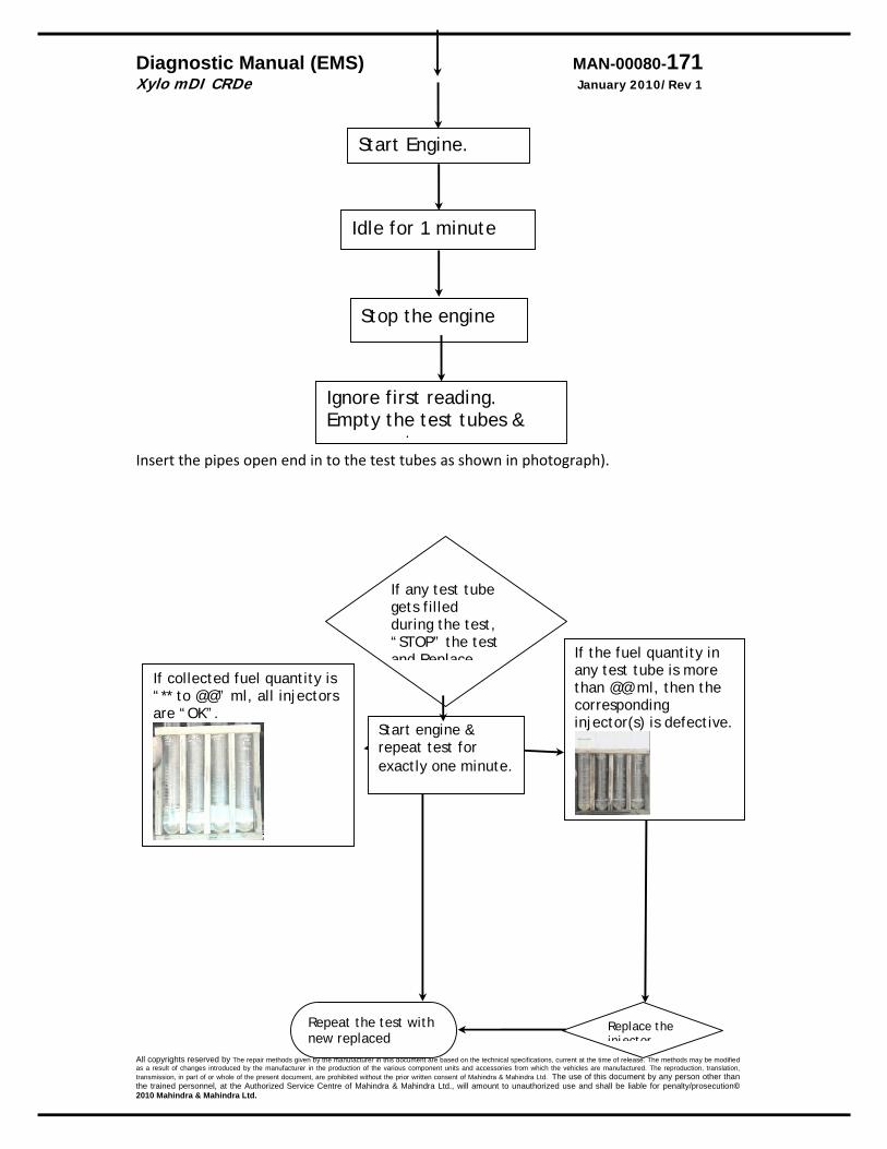
Diagnostic Manual (EMS) MAN-00080-171 Xylo mDI CRDe January 2010/Rev 1
All copyrights reserved by The repair methods given by the manufacturer in this document are based on the technical specifications, current at the time of release. The methods may be modified as a result of changes introduced by the manufacturer in the production of the various component units and accessories from which the vehicles are manufactured. The reproduction, translation, transmission, in part of or whole of the present document, are prohibited without the prior written consent of Mahindra & Mahindra Ltd. The use of this document by any person other than the trained personnel, at the Authorized Service Centre of Mahindra & Mahindra Ltd., will amount to unauthorized use and shall be liable for penalty/prosecution© 2010 Mahindra & Mahindra Ltd.
Insert the pipes open end in to the test tubes as shown in photograph).
If any test tube gets filled during the test, “STOP” the test and Replace
Start engine & repeat test for exactly one minute.
If collected fuel quantity is “** to @@” ml, all injectors are “OK”.
If the fuel quantity in any test tube is more than @@ ml, then the corresponding injector(s) is defective.
Replace the injector
Repeat the test with new replaced
Start Engine.
Idle for 1 minute
Stop the engine
Ignore first reading. Empty the test tubes &
t
Diagnostic Manual (EMS) MAN-00080-172 Xylo mDI CRDe January 2010/Rev 1
All copyrights reserved by The repair methods given by the manufacturer in this document are based on the technical specifications, current at the time of release. The methods may be modified as a result of changes introduced by the manufacturer in the production of the various component units and accessories from which the vehicles are manufactured. The reproduction, translation, transmission, in part of or whole of the present document, are prohibited without the prior written consent of Mahindra & Mahindra Ltd. The use of this document by any person other than the trained personnel, at the Authorized Service Centre of Mahindra & Mahindra Ltd., will amount to unauthorized use and shall be liable for penalty/prosecution© 2010 Mahindra & Mahindra Ltd.
The root cause for the injectors stuck open or close is the presence of water in the fuel or poor fuel quality. Investigate & advice the customer accordingly to avoid repeat failure. In case of water – please advise the customer how to drain water when the indicator comes ON. If it is suspected due to poor fuel quality‐ please advise accordingly.
SBD #2

Diagnostic Manual (EMS) MAN-00080-173 Xylo mDI CRDe January 2010/Rev 1
All copyrights reserved by The repair methods given by the manufacturer in this document are based on the technical specifications, current at the time of release. The methods may be modified as a result of changes introduced by the manufacturer in the production of the various component units and accessories from which the vehicles are manufactured. The reproduction, translation, transmission, in part of or whole of the present document, are prohibited without the prior written consent of Mahindra & Mahindra Ltd. The use of this document by any person other than the trained personnel, at the Authorized Service Centre of Mahindra & Mahindra Ltd., will amount to unauthorized use and shall be liable for penalty/prosecution© 2010 Mahindra & Mahindra Ltd.
Conformity Check Resistance Values Coolant temperature Sensor/ Fuel Temperature sensor
Temperature Resistance Min kΏ Resistance Max kΏ 10 8.244 10.661 20 2.262 2.76 80 0.304 0.342 100 0.178 0.196
Accelerator pedal Poti 1 Poti 2 Accelerator pedal:‐ 0% 2.160KOhm, 2.672KOhm Accelerator pedal :‐100% 1.321KOhm 2.112KOhm Poti 1 1.2 kΏ ± 0.4 1.7 kΏ ± 0.4
HFM (Air flow)
Air flow R Min(Kohm) R Max (Kohm) ‐10 7.942 9.3 0 5.119 5.892 30 1.573 1.752 60 0.565 0.654 90 0.238 0.285 100 0.184 0.222
Injector Solenoid coil Nominal value: 0.255 Ohm Min: 0.215 Ohm, Max: 0.295 Ohm Measured at 20‐70 degrees centigrade.
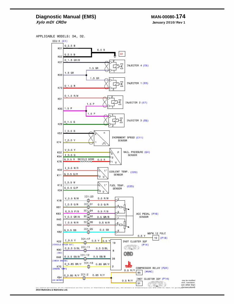
Diagnostic Manual (EMS) MAN-00080-174 Xylo mDI CRDe January 2010/Rev 1
All copyrights reserved by The repair methods given by the manufacturer in this document are based on the technical specifications, current at the time of release. The methods may be modified as a result of changes introduced by the manufacturer in the production of the various component units and accessories from which the vehicles are manufactured. The reproduction, translation, transmission, in part of or whole of the present document, are prohibited without the prior written consent of Mahindra & Mahindra Ltd. The use of this document by any person other than the trained personnel, at the Authorized Service Centre of Mahindra & Mahindra Ltd., will amount to unauthorized use and shall be liable for penalty/prosecution© 2010 Mahindra & Mahindra Ltd.

Diagnostic Manual (EMS) MAN-00080-175 Xylo mDI CRDe January 2010/Rev 1
All copyrights reserved by The repair methods given by the manufacturer in this document are based on the technical specifications, current at the time of release. The methods may be modified as a result of changes introduced by the manufacturer in the production of the various component units and accessories from which the vehicles are manufactured. The reproduction, translation, transmission, in part of or whole of the present document, are prohibited without the prior written consent of Mahindra & Mahindra Ltd. The use of this document by any person other than the trained personnel, at the Authorized Service Centre of Mahindra & Mahindra Ltd., will amount to unauthorized use and shall be liable for penalty/prosecution© 2010 Mahindra & Mahindra Ltd.