diagnostic tester suzuki sdt-ii handouts for...
TRANSCRIPT
Diagnostic Tester
Suzuki SDT-II
Handouts for Training
CONTENTS
1
1. INTRODUCTION
5. SCAN LOG
6. COMMON DIAGNOSIS FUNCTIONS
2. INSTALLATION OF SOFTWARE
4. HOME SCREEN
3. INITIAL SETUP
Suzuki SDT-II Handouts for Training
7. VEHICLE HEALTH
8. COMMUNICATION BUS CHECK
12. DATA LIST (GRAPH FUNCTION)
13. ACTIVE TEST
9. DTC
11. DATA LIST (GENERAL FUNCTIONS)
10. REVIEW SAVED DATA
14. UTILITY
15. DIAGNOSTIC REPORT
16. IMMOBILIZER
1. INTRODUCTION
2
1.1 SDT-II Development schedule
1.2 SDT-II Setup
1.3 SDT-II Functional characteristics
Suzuki SDT-II Handouts for Training
1. Introduction (1)
3
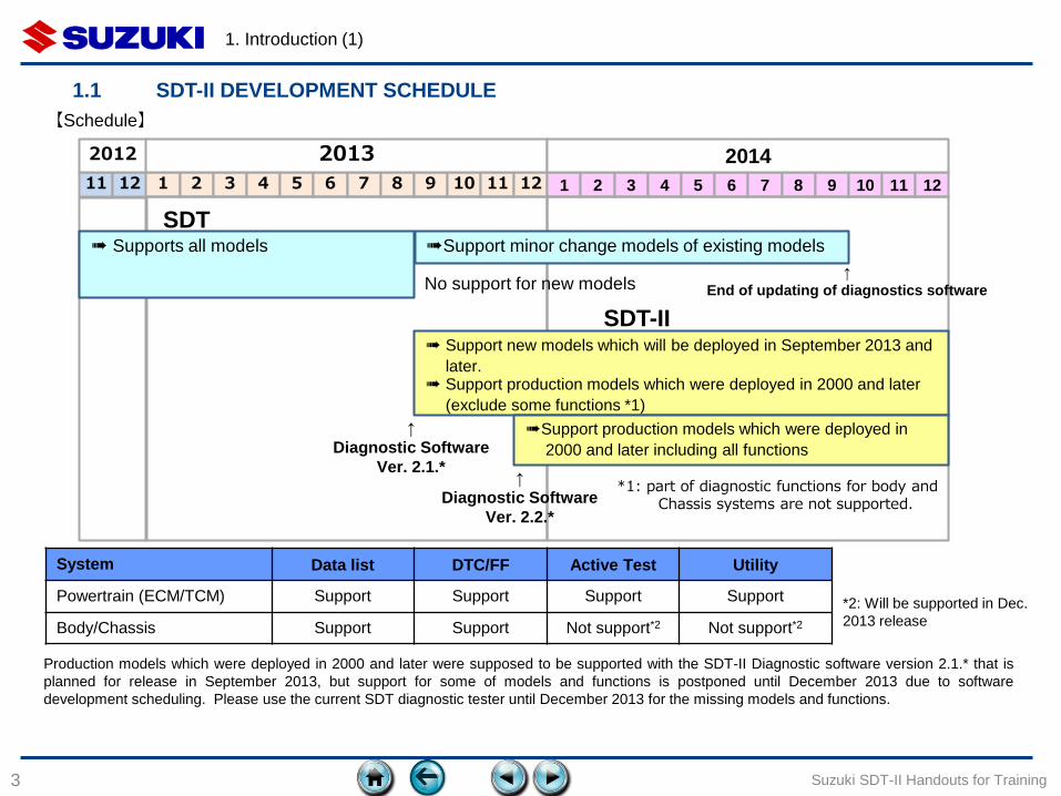
1.1 SDT-II DEVELOPMENT SCHEDULE
Suzuki SDT-II Handouts for Training
Production models which were deployed in 2000 and later were supposed to be supported with the SDT-II Diagnostic software version 2.1.* that is
planned for release in September 2013, but support for some of models and functions is postponed until December 2013 due to software
development scheduling. Please use the current SDT diagnostic tester until December 2013 for the missing models and functions.
【Schedule】
System Data list DTC/FF Active Test Utility
Powertrain (ECM/TCM) Support Support Support Support
Body/Chassis Support Support Not support*2 Not support*2
*2: Will be supported in Dec.
2013 release
11 12
2012
1 2 3 4 5 6 7 8 9 10 11 12
2013
1 2 3 4 5 6 7 8 9 10 11 12
2014
SDT
No support for new models
➠ Supports all models ➠Support minor change models of existing models
*1: part of diagnostic functions for body and Chassis systems are not supported.
↑
End of updating of diagnostics software
SDT-II ➠ Support new models which will be deployed in September 2013 and
later. ➠ Support production models which were deployed in 2000 and later
(exclude some functions *1)
↑
Diagnostic Software
Ver. 2.1.*
➠Support production models which were deployed in
2000 and later including all functions
↑
Diagnostic Software
Ver. 2.2.*
1. Introduction (2)
4
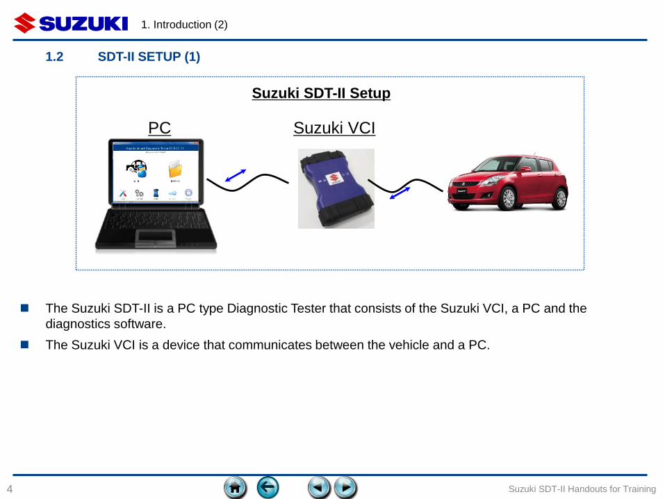
1.2 SDT-II SETUP (1)
Suzuki SDT-II Handouts for Training
PC Suzuki VCI
Suzuki SDT-II Setup
The Suzuki SDT-II is a PC type Diagnostic Tester that consists of the Suzuki VCI, a PC and the
diagnostics software.
The Suzuki VCI is a device that communicates between the vehicle and a PC.
1. Introduction (3)
5
1.2 SDT-II SETUP (2)
Suzuki SDT-II Handouts for Training
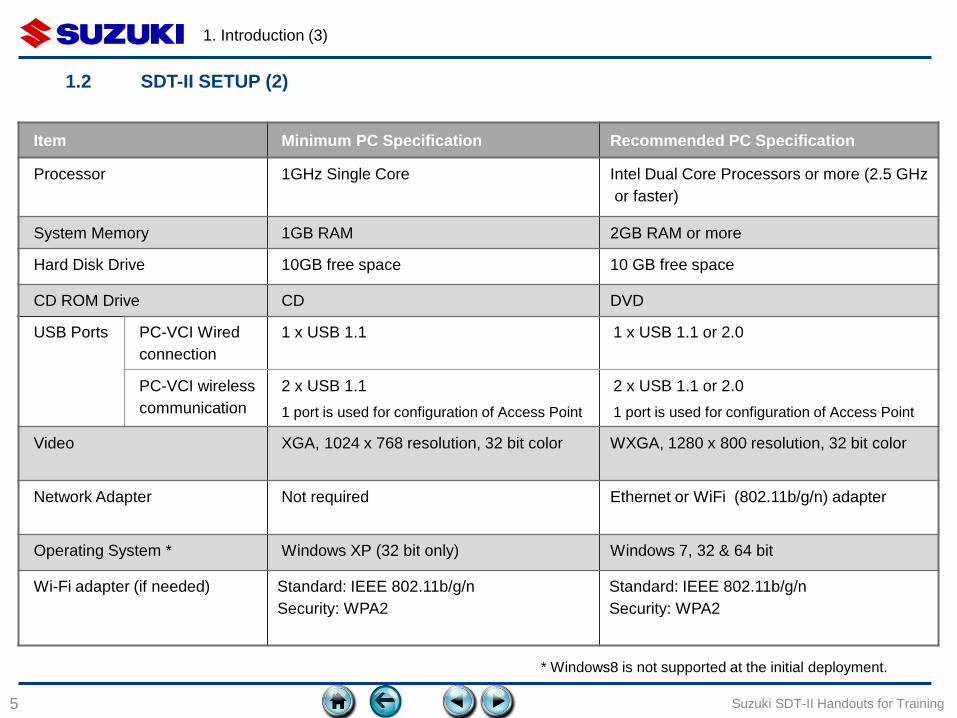
* Windows8 is not supported at the initial deployment.
Item Minimum PC Specification Recommended PC Specification
Processor 1GHz Single Core Intel Dual Core Processors or more (2.5 GHz
or faster)
System Memory 1GB RAM 2GB RAM or more
Hard Disk Drive 10GB free space 10 GB free space
CD ROM Drive CD DVD
USB Ports PC-VCI Wired
connection
1 x USB 1.1 1 x USB 1.1 or 2.0
PC-VCI wireless
communication
2 x USB 1.1
1 port is used for configuration of Access Point
2 x USB 1.1 or 2.0
1 port is used for configuration of Access Point
Video XGA, 1024 x 768 resolution, 32 bit color WXGA, 1280 x 800 resolution, 32 bit color
Network Adapter Not required Ethernet or WiFi (802.11b/g/n) adapter
Operating System * Windows XP (32 bit only) Windows 7, 32 & 64 bit
Wi-Fi adapter (if needed) Standard: IEEE 802.11b/g/n
Security: WPA2
Standard: IEEE 802.11b/g/n
Security: WPA2
1. Introduction (4)
6
1.2 SDT-II SETUP (3)
Suzuki SDT-II Handouts for Training
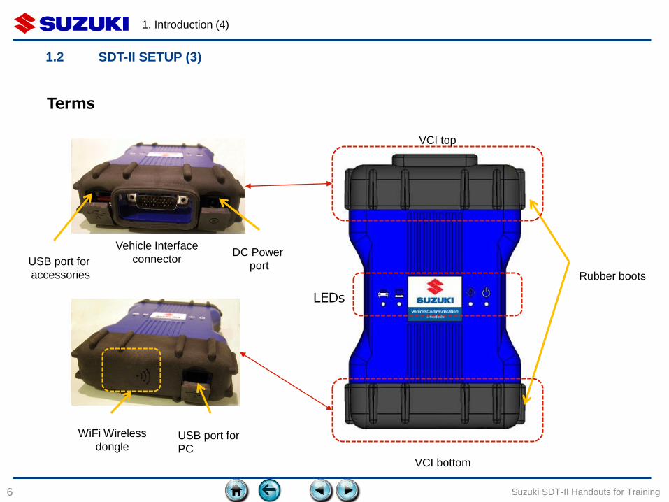
LEDs
Terms
Rubber boots
Vehicle Interface
connector USB port for
accessories
DC Power
port
USB port for
PC
WiFi Wireless
dongle
VCI bottom
VCI top
1. Introduction (5)
7
1.2 SDT-II SETUP (4)
Suzuki SDT-II Handouts for Training
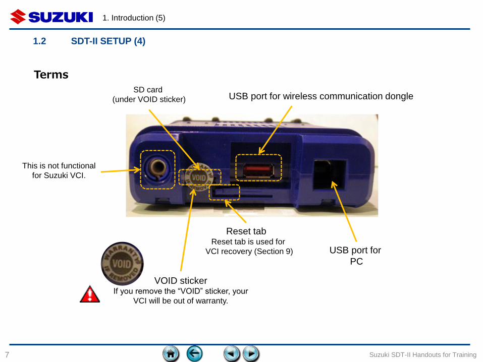
USB port for
PC
VOID sticker If you remove the “VOID” sticker, your
VCI will be out of warranty.
Reset tab
SD card
(under VOID sticker)
This is not functional
for Suzuki VCI.
USB port for wireless communication dongle
Reset tab is used for
VCI recovery (Section 9)
Terms
1. Introduction (6)
8
1.2 SDT-II SETUP (5)
Suzuki SDT-II Handouts for Training
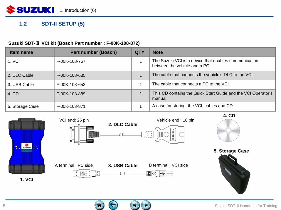
3. USB Cable
2. DLC Cable
1. VCI
5. Storage Case
4. CD
Item name Part number (Bosch) QTY Note
1. VCI F-00K-108-767 1 The Suzuki VCI is a device that enables communication
between the vehicle and a PC.
2. DLC Cable F-00K-108-635 1 The cable that connects the vehicle’s DLC to the VCI.
3. USB Cable F-00K-108-653 1 The cable that connects a PC to the VCI.
4. CD F-00K-108-889 1 This CD contains the Quick Start Guide and the VCI Operator’s
manual.
5. Storage Case F-00K-108-871 1 A case for storing the VCI, cables and CD.
A terminal : PC side
Vehicle end : 16 pin VCI end: 26 pin
Suzuki SDT-Ⅱ VCI kit (Bosch Part number : F-00K-108-872)
B terminal : VCI side
1. Introduction (7)
9
1.2 SDT-II SETUP (6)
Suzuki SDT-II Handouts for Training
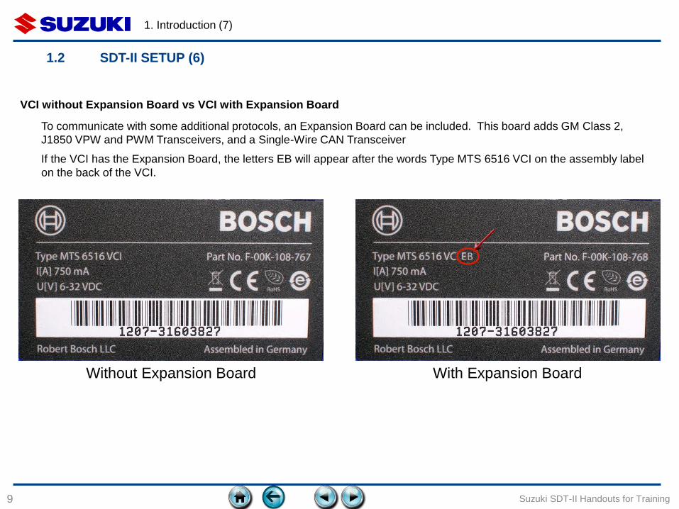
To communicate with some additional protocols, an Expansion Board can be included. This board adds GM Class 2,
J1850 VPW and PWM Transceivers, and a Single-Wire CAN Transceiver
If the VCI has the Expansion Board, the letters EB will appear after the words Type MTS 6516 VCI on the assembly label
on the back of the VCI.
Without Expansion Board With Expansion Board
VCI without Expansion Board vs VCI with Expansion Board
1. Introduction (8)
10
1.2 SDT-II SETUP (7)
Suzuki SDT-II Handouts for Training
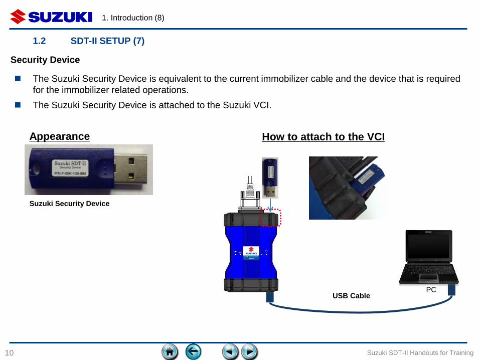
Suzuki Security Device
USB Cable PC
The Suzuki Security Device is equivalent to the current immobilizer cable and the device that is required
for the immobilizer related operations.
The Suzuki Security Device is attached to the Suzuki VCI.
Appearance How to attach to the VCI
Security Device

Item name Part number
(Bosch) Note
1. Wireless
communication dongle
F-00K-108-665 The wireless communication (WiFi) dongle is plugged into the USB port of
the Suzuki VCI and is used in conjunction with an Access point for
communication between the Suzuki VCI and PC.
When you place an order for the Wireless communication dongle, make sure
the product is certified in your country.
To install an Access Point in your work area, you should consult a wireless
communication professional. Note: WPA2 level security equipment is a
mandatory requirement for the Access Point.
2. DC Power supply F-00K-108-843 The DC Power supply will be used to supply power to VCI at the office when
wireless communication is set up and power from vehicle to the VCI is not
available.
3. Trigger switch F-00K-108-330 The trigger switch is plugged into the accessory USB port of the VCI. When
you use the Suzuki VCI as a Data Recorder, the trigger switch will be used to
initiate data saving at any time.
1. Introduction (9)
11
1.2 SDT-II SETUP (8)
Suzuki SDT-II Handouts for Training
Optional purchase items
1. Introduction (10)
12
1.3 SDT-II FUNCTIONAL CHARACTERISTICS
Suzuki SDT-II Handouts for Training
1. PC-type high performance diagnostic tester
The display of PC can show more detailed information on the screen at once since it has a wider display than handheld-type
diagnostic testers.
It is possible to handle large volumes of data by using the high processing capability of a PC.
2. Automatic vehicle identification and automatic DTC reading from all systems
Automatic vehicle identification and automatic DTC reading at the beginning of a diagnostic session removes the possibility
of a technician forgetting to check DTCs.
3. Diagnostic Report
Presenting a diagnostic results report to the customer will help to increase CS and profitability.
4. Easy to manage diagnostic records
All diagnostic data (ie: DTC and data monitor) will be recorded with VIN (Vehicle Identification Number). It makes it
easy to manage diagnostic history data.
5. Wireless LAN (Wi-Fi)
Wireless communication between VCI and PC via an access point is supported.
2. INSTALLATION OF SOFTWARE
13
2.1 Preparation
2.2 Installing SDT-II software on the PC
2.3 Write software to the VCI
2.4 VCI software recovery procedure
Suzuki SDT-II Handouts for Training
2. Installation of Software (1)
14
2.1 PREPARATION (1)
Suzuki SDT-II Handouts for Training
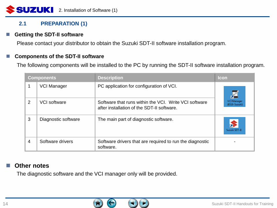
Getting the SDT-II software
Please contact your distributor to obtain the Suzuki SDT-II software installation program.
Components of the SDT-II software
The following components will be installed to the PC by running the SDT-II software installation program.
Components Description Icon
1 VCI Manager PC application for configuration of VCI.
2 VCI software Software that runs within the VCI. Write VCI software
after installation of the SDT-II software.
3 Diagnostic software The main part of diagnostic software.
4 Software drivers Software drivers that are required to run the diagnostic
software.
-
The diagnostic software and the VCI manager only will be provided.
Other notes
2. Installation of Software (2)
15
2.2 INSTALLING SDT-II SOFTWARE ON THE PC (1)
Suzuki SDT-II Handouts for Training
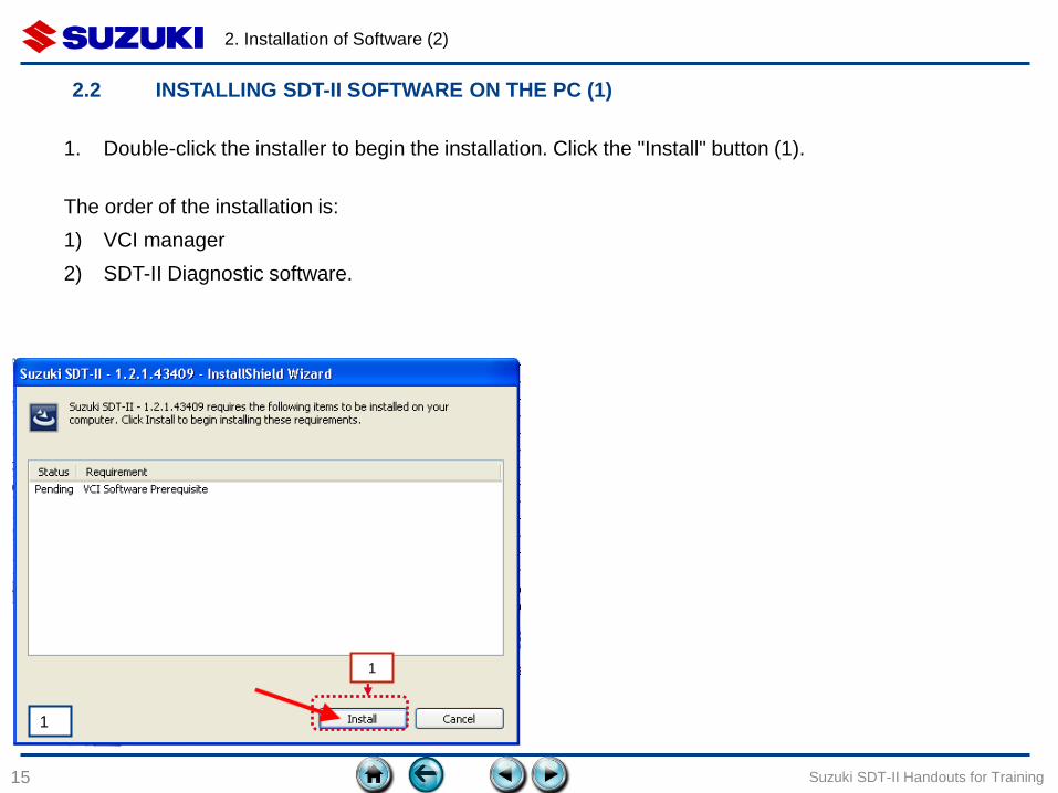
1. Double-click the installer to begin the installation. Click the "Install" button (1).
The order of the installation is:
1) VCI manager
2) SDT-II Diagnostic software.
1
1
2. Installation of Software (3)
16 Suzuki SDT-II Handouts for Training
3 2
2 3
2.2 INSTALLING SDT-II SOFTWARE ON THE PC (2)
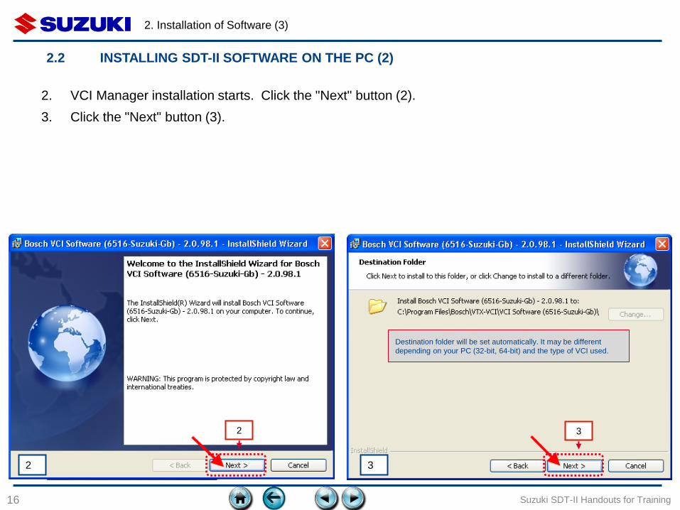
2. VCI Manager installation starts. Click the "Next" button (2).
3. Click the "Next" button (3).
Destination folder will be set automatically. It may be different
depending on your PC (32-bit, 64-bit) and the type of VCI used.
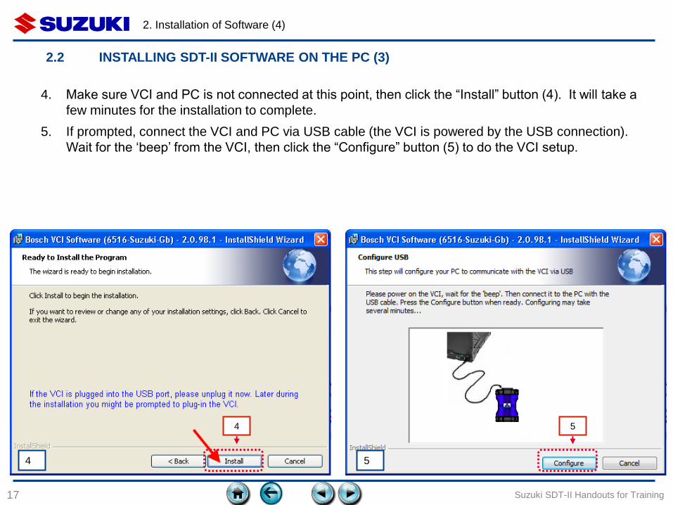
4. Make sure VCI and PC is not connected at this point, then click the “Install” button (4). It will take a
few minutes for the installation to complete.
5. If prompted, connect the VCI and PC via USB cable (the VCI is powered by the USB connection).
Wait for the ‘beep’ from the VCI, then click the “Configure” button (5) to do the VCI setup.
2. Installation of Software (4)
17 Suzuki SDT-II Handouts for Training
4 5
2.2 INSTALLING SDT-II SOFTWARE ON THE PC (3)
5 4
2. Installation of Software (5)
18 Suzuki SDT-II Handouts for Training
6
7
2.2 INSTALLING SDT-II SOFTWARE ON THE PC (4)
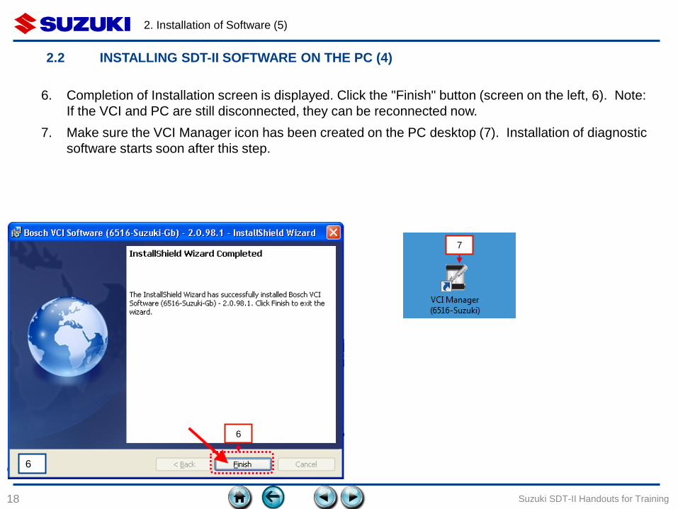
6. Completion of Installation screen is displayed. Click the "Finish" button (screen on the left, 6). Note:
If the VCI and PC are still disconnected, they can be reconnected now.
7. Make sure the VCI Manager icon has been created on the PC desktop (7). Installation of diagnostic
software starts soon after this step.
6
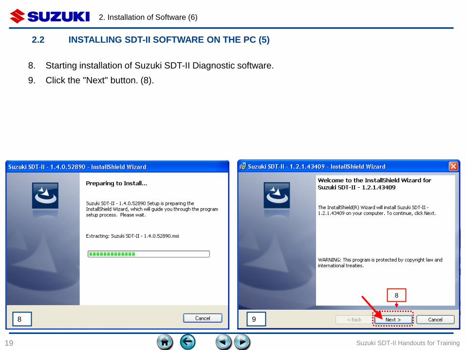
8. Starting installation of Suzuki SDT-II Diagnostic software.
9. Click the "Next" button. (8).
2. Installation of Software (6)
19 Suzuki SDT-II Handouts for Training
8
2.2 INSTALLING SDT-II SOFTWARE ON THE PC (5)
9 8
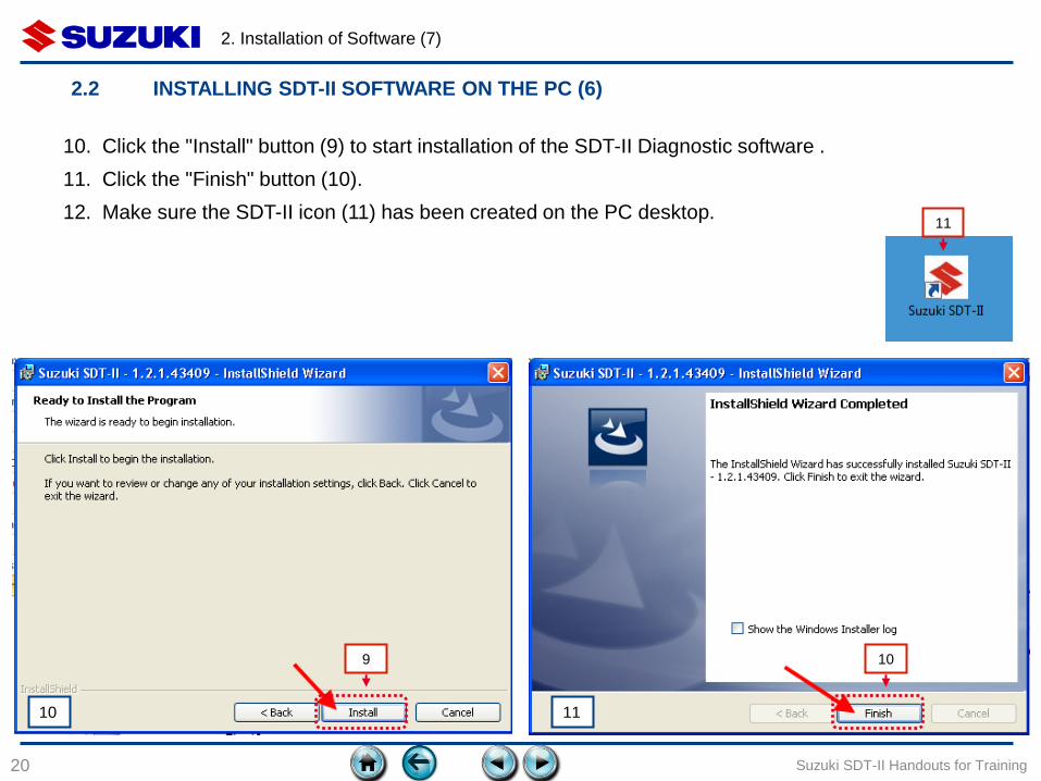
10. Click the "Install" button (9) to start installation of the SDT-II Diagnostic software .
11. Click the "Finish" button (10).
12. Make sure the SDT-II icon (11) has been created on the PC desktop.
2. Installation of Software (7)
20 Suzuki SDT-II Handouts for Training
9 10
11
2.2 INSTALLING SDT-II SOFTWARE ON THE PC (6)
11 10
2. Installation of Software (8)
21 Suzuki SDT-II Handouts for Training
☞ The VCI is shipped without software (firmware) programmed inside. Before the VCI can be used, the
first configuration step is writing software to the VCI via the PC. This section provides the procedure. It
should be noted that the software is for VCI setup (it is not diagnostic software).
If you are using a notebook PC, connect the AC adapter to the PC so power does not to drop due to
low battery while programming.
Before writing software to the VCI, exit all the applications on your PC.
Before writing software to the VCI, remove USB devices other than the keyboard and mouse from the
PC.
A warning will be shown to not disconnect the USB cable in the middle of a procedure. This
instruction must be followed. Disconnecting the USB cable or turning off the PC while programming
the VCI can damage the VCI.
If writing software to the VCI fails, follow the instructions in "Chapter 2.4: “Recovery”.
2.3 WRITE SOFTWARE TO THE VCI (1)
Notes for writing software to the VCI
2. Installation of Software (9)
22 Suzuki SDT-II Handouts for Training
USB cable
PC
1
2
3
4
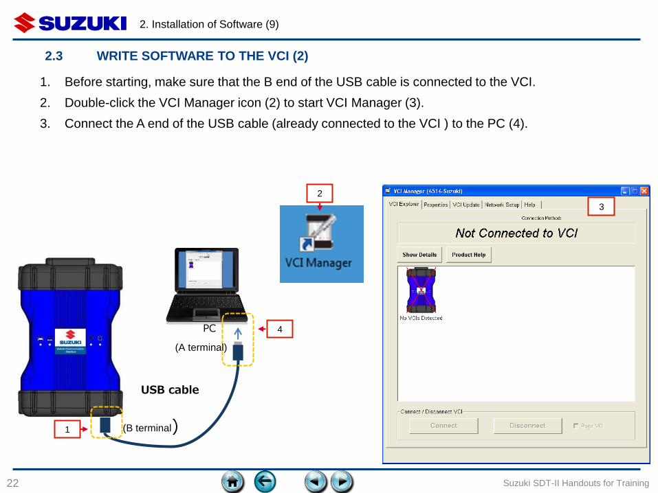
2.3 WRITE SOFTWARE TO THE VCI (2)
(A terminal)
(B terminal)
1. Before starting, make sure that the B end of the USB cable is connected to the VCI.
2. Double-click the VCI Manager icon (2) to start VCI Manager (3).
3. Connect the A end of the USB cable (already connected to the VCI ) to the PC (4).
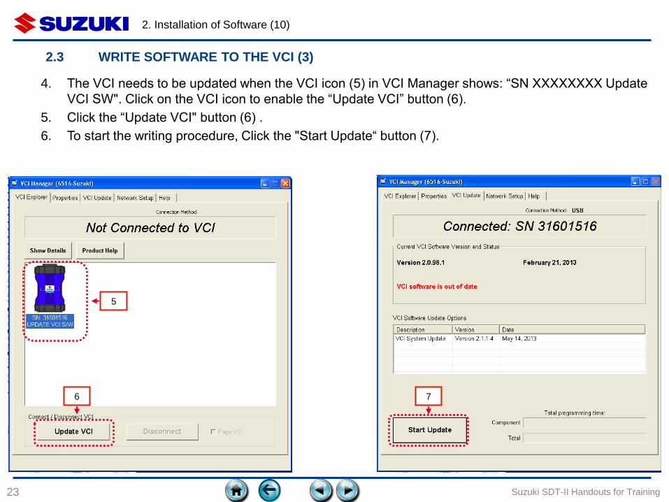
4. The VCI needs to be updated when the VCI icon (5) in VCI Manager shows: “SN XXXXXXXX Update
VCI SW". Click on the VCI icon to enable the “Update VCI” button (6).
5. Click the “Update VCI" button (6) .
6. To start the writing procedure, Click the "Start Update“ button (7).
2. Installation of Software (10)
23 Suzuki SDT-II Handouts for Training
6
5
7
2.3 WRITE SOFTWARE TO THE VCI (3)
2. Installation of Software (11)
24 Suzuki SDT-II Handouts for Training
8 9
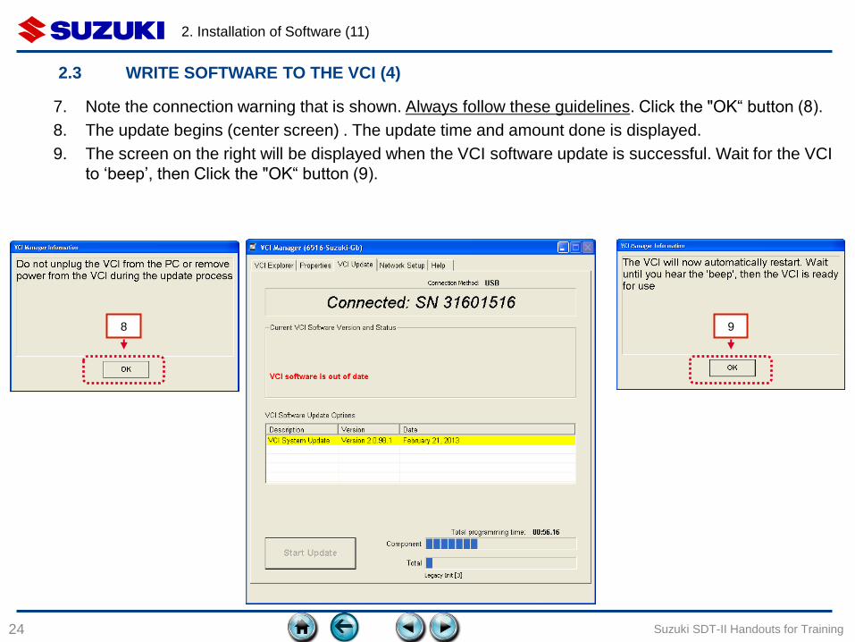
2.3 WRITE SOFTWARE TO THE VCI (4)
7. Note the connection warning that is shown. Always follow these guidelines. Click the "OK“ button (8).
8. The update begins (center screen) . The update time and amount done is displayed.
9. The screen on the right will be displayed when the VCI software update is successful. Wait for the VCI
to ‘beep’, then Click the "OK“ button (9).
2. Installation of Software (12)
25 Suzuki SDT-II Handouts for Training
11
10 12
13
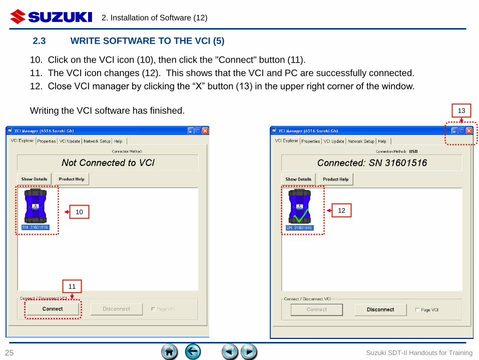
2.3 WRITE SOFTWARE TO THE VCI (5)
10. Click on the VCI icon (10), then click the "Connect" button (11).
11. The VCI icon changes (12). This shows that the VCI and PC are successfully connected.
12. Close VCI manager by clicking the “X” button (13) in the upper right corner of the window.
Writing the VCI software has finished.
2. Installation of Software (13)
26
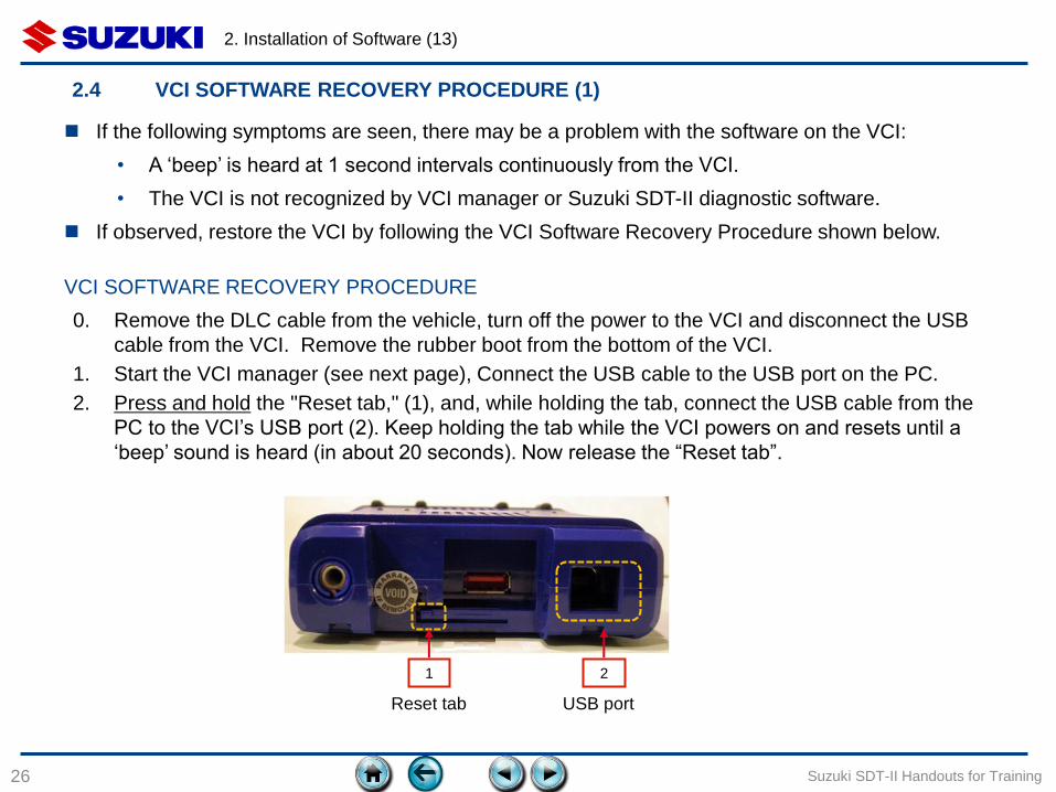
2.4 VCI SOFTWARE RECOVERY PROCEDURE (1)
Suzuki SDT-II Handouts for Training
1 2
0. Remove the DLC cable from the vehicle, turn off the power to the VCI and disconnect the USB
cable from the VCI. Remove the rubber boot from the bottom of the VCI.
1. Start the VCI manager (see next page), Connect the USB cable to the USB port on the PC.
2. Press and hold the "Reset tab," (1), and, while holding the tab, connect the USB cable from the
PC to the VCI’s USB port (2). Keep holding the tab while the VCI powers on and resets until a
‘beep’ sound is heard (in about 20 seconds). Now release the “Reset tab”.
If the following symptoms are seen, there may be a problem with the software on the VCI:
• A ‘beep’ is heard at 1 second intervals continuously from the VCI.
• The VCI is not recognized by VCI manager or Suzuki SDT-II diagnostic software.
If observed, restore the VCI by following the VCI Software Recovery Procedure shown below.
VCI SOFTWARE RECOVERY PROCEDURE
USB port Reset tab

2. Installation of Software (14)
27 Suzuki SDT-II Handouts for Training
3. The VCI is ready to be recovered when the VCI manager screen says “SN: XXXXXXXX Recover” (4).
Click the VCI icon to enable the “Recover” button (4). If you do not see this screen, then you may not
be in recovery mode. Retry step 2 again (be sure to hold the “Reset tab” long enough after connecting
the USB cable).
4. Click the “Recover” button (5) to start the recovery process. The “Start Update” screen (shown on the
left side of the next page) will be displayed.
SN XXXXXXXX represents the last 8 digits of the serial number of the VCI.
3
5
4
2.4 VCI SOFTWARE RECOVERY PROCEDURE (2)

2. Installation of Software (15)
28 Suzuki SDT-II Handouts for Training
6
7
2.4 VCI SOFTWARE RECOVERY PROCEDURE (3)
5. To start the update, Click the "Start Update" button (6).
6. Note the connection warning that is shown. Always follow these guidelines. Click the "OK“ button (7).
The update begins.
2. Installation of Software (16)
29 Suzuki SDT-II Handouts for Training
8
2.4 VCI SOFTWARE RECOVERY PROCEDURE (3)
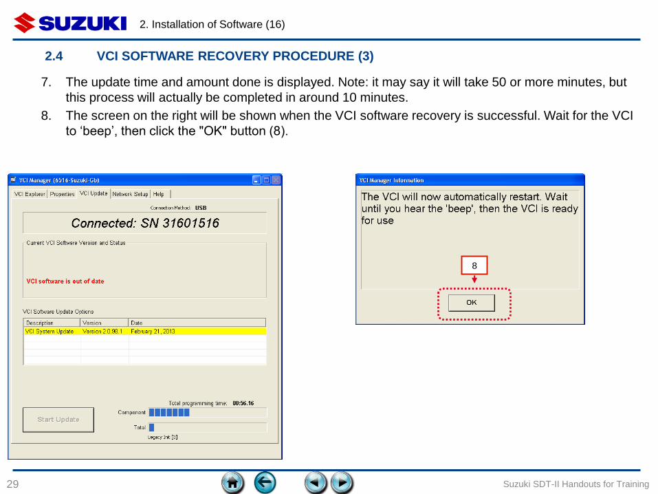
7. The update time and amount done is displayed. Note: it may say it will take 50 or more minutes, but
this process will actually be completed in around 10 minutes.
8. The screen on the right will be shown when the VCI software recovery is successful. Wait for the VCI
to ‘beep’, then click the "OK" button (8).

2. Installation of Software (17)
30 Suzuki SDT-II Handouts for Training
9. Click on the VCI icon (9), then click the "Connect" button (10).
10. The VCI icon changes (11), showing that the VCI and PC are successfully connected.
11. Close VCI manager by clicking the “X” button (12) in the upper right corner of the window.
Writing the VCI software has finished.
10
9 11
12
2.4 VCI SOFTWARE RECOVERY PROCEDURE (5)
3. INITIAL SETUP
31
3.1 Setup VCI and components
3.2 Connection between PC and VCI
3.3 Start SDT-II diagnostic software
3.4 Connection between vehicle and VCI
Suzuki SDT-II Handouts for Training
3. Initial setup (1)
32 Suzuki SDT-II Handouts for Training
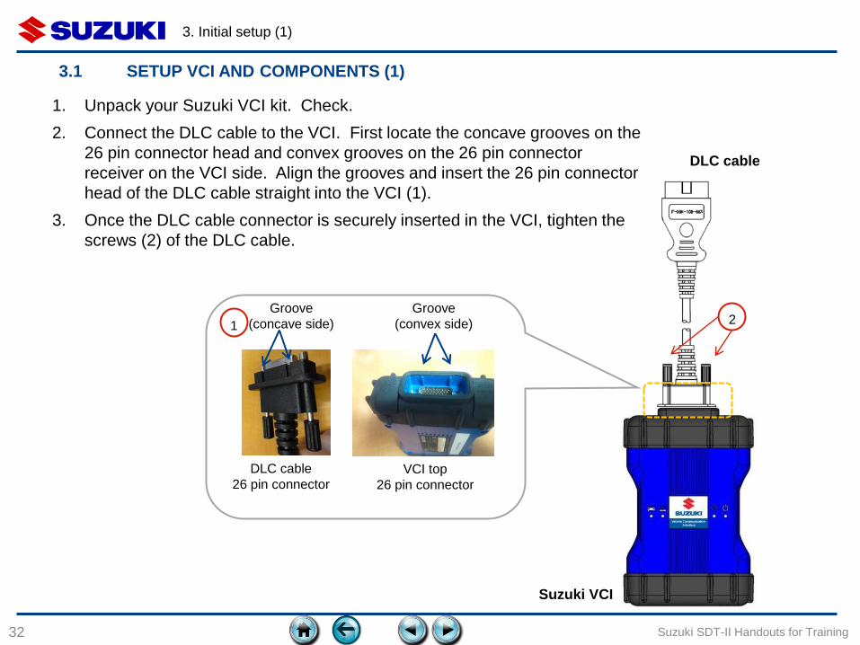
3.1 SETUP VCI AND COMPONENTS (1)
2 1
VCI top
26 pin connector
Groove
(convex side)
Groove
(concave side)
DLC cable
26 pin connector
DLC cable
Suzuki VCI
1. Unpack your Suzuki VCI kit. Check.
2. Connect the DLC cable to the VCI. First locate the concave grooves on the
26 pin connector head and convex grooves on the 26 pin connector
receiver on the VCI side. Align the grooves and insert the 26 pin connector
head of the DLC cable straight into the VCI (1).
3. Once the DLC cable connector is securely inserted in the VCI, tighten the
screws (2) of the DLC cable.
3. Initial setup (2)
33 Suzuki SDT-II Handouts for Training
3.1 SETUP VCI AND COMPONENTS (2)
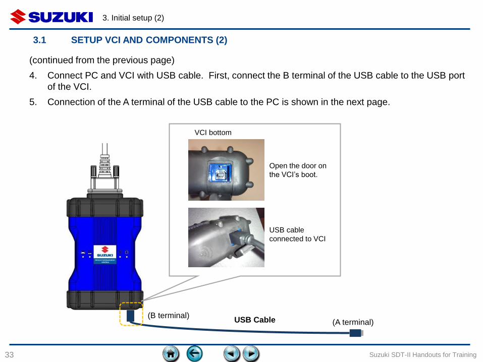
(continued from the previous page)
4. Connect PC and VCI with USB cable. First, connect the B terminal of the USB cable to the USB port
of the VCI.
5. Connection of the A terminal of the USB cable to the PC is shown in the next page.
VCI bottom
Open the door on
the VCI’s boot.
USB cable
connected to VCI
(A terminal) (B terminal)
USB Cable
3. Initial setup (3)
34 Suzuki SDT-II Handouts for Training
3.2 CONNECTION BETWEEN PC AND VCI
PC
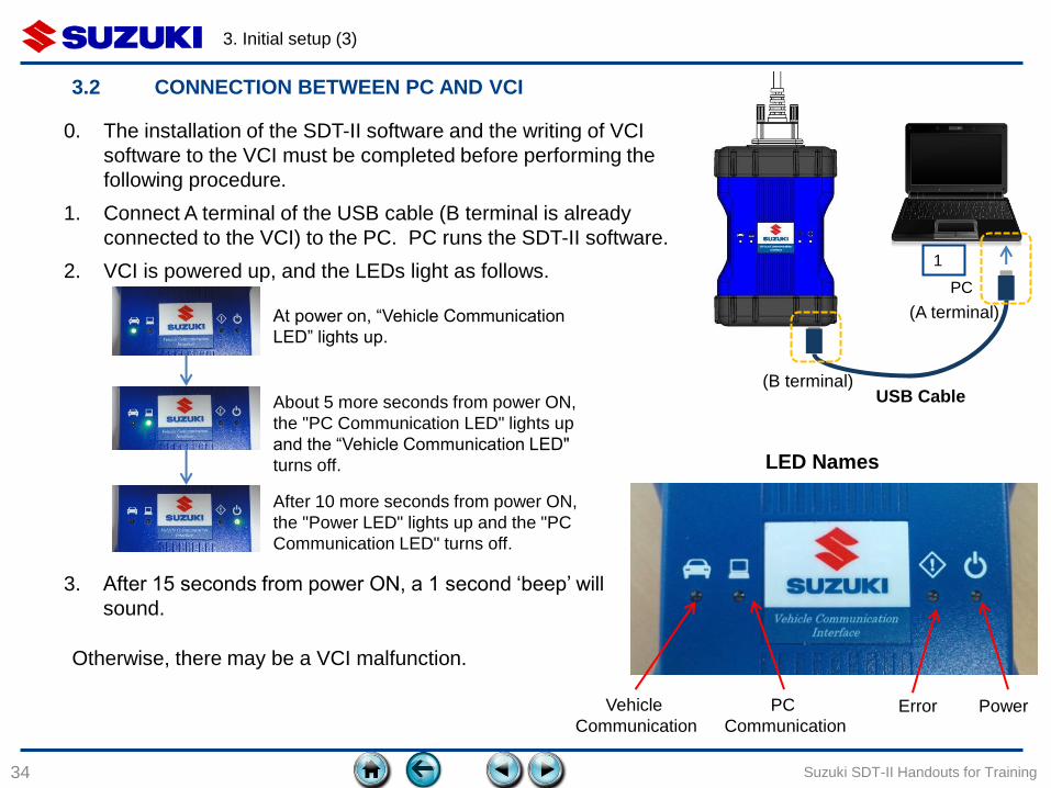
0. The installation of the SDT-II software and the writing of VCI
software to the VCI must be completed before performing the
following procedure.
1. Connect A terminal of the USB cable (B terminal is already
connected to the VCI) to the PC. PC runs the SDT-II software.
2. VCI is powered up, and the LEDs light as follows.
3. After 15 seconds from power ON, a 1 second ‘beep’ will
sound.
At power on, “Vehicle Communication
LED” lights up.
About 5 more seconds from power ON,
the "PC Communication LED" lights up
and the “Vehicle Communication LED"
turns off.
After 10 more seconds from power ON,
the "Power LED" lights up and the "PC
Communication LED" turns off.
1
Otherwise, there may be a VCI malfunction.
(A terminal)
(B terminal) USB Cable
Vehicle
Communication
PC
Communication Error Power
LED Names
3. Initial setup (4)
35 Suzuki SDT-II Handouts for Training
3.3 START THE SDT-II DIAGNOSTIC SOFTWARE
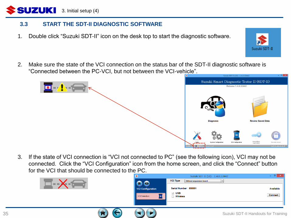
1. Double click “Suzuki SDT-II” icon on the desk top to start the diagnostic software.
2. Make sure the state of the VCI connection on the status bar of the SDT-II diagnostic software is
“Connected between the PC-VCI, but not between the VCI-vehicle”.
3. If the state of VCI connection is “VCI not connected to PC” (see the following icon), VCI may not be
connected. Click the “VCI Configuration” icon from the home screen, and click the “Connect” button
for the VCI that should be connected to the PC.
3. Initial setup (5)
36 Suzuki SDT-II Handouts for Training
3.4 CONNECTION BETWEEN VEHICLE AND VCI
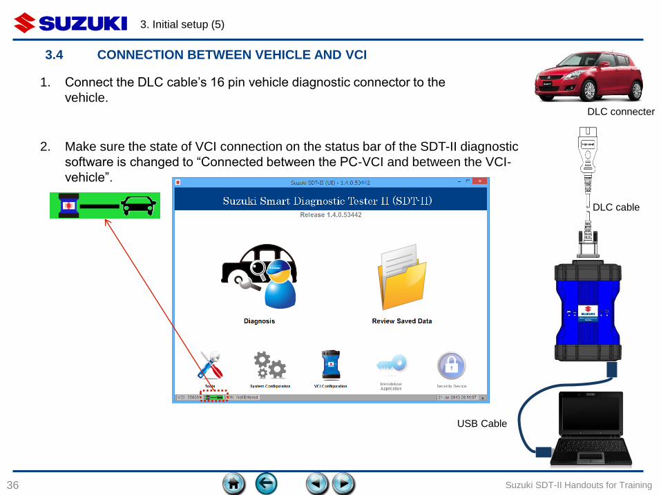
1. Connect the DLC cable’s 16 pin vehicle diagnostic connector to the
vehicle.
2. Make sure the state of VCI connection on the status bar of the SDT-II diagnostic
software is changed to “Connected between the PC-VCI and between the VCI-
vehicle”.
DLC cable
DLC connecter
USB Cable
4. THE HOME SCREEN
37
4.1 Home screen description
4.2 Icon description
4.3 System configuration
4.4 Setting dealer and technician name
4.5 Setting the VCI type
4.6 Status Bar description
Suzuki SDT-II Handouts for Training
4. The Home screen (1)
38 Suzuki SDT-II Handouts for Training
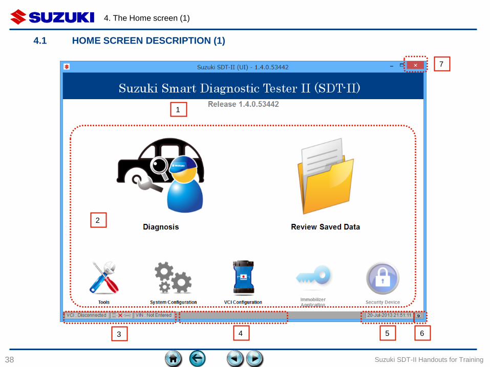
4.1 HOME SCREEN DESCRIPTION (1)
1
3 4 5 6
2
7
4. The Home screen (2)
39 Suzuki SDT-II Handouts for Training
Item Description
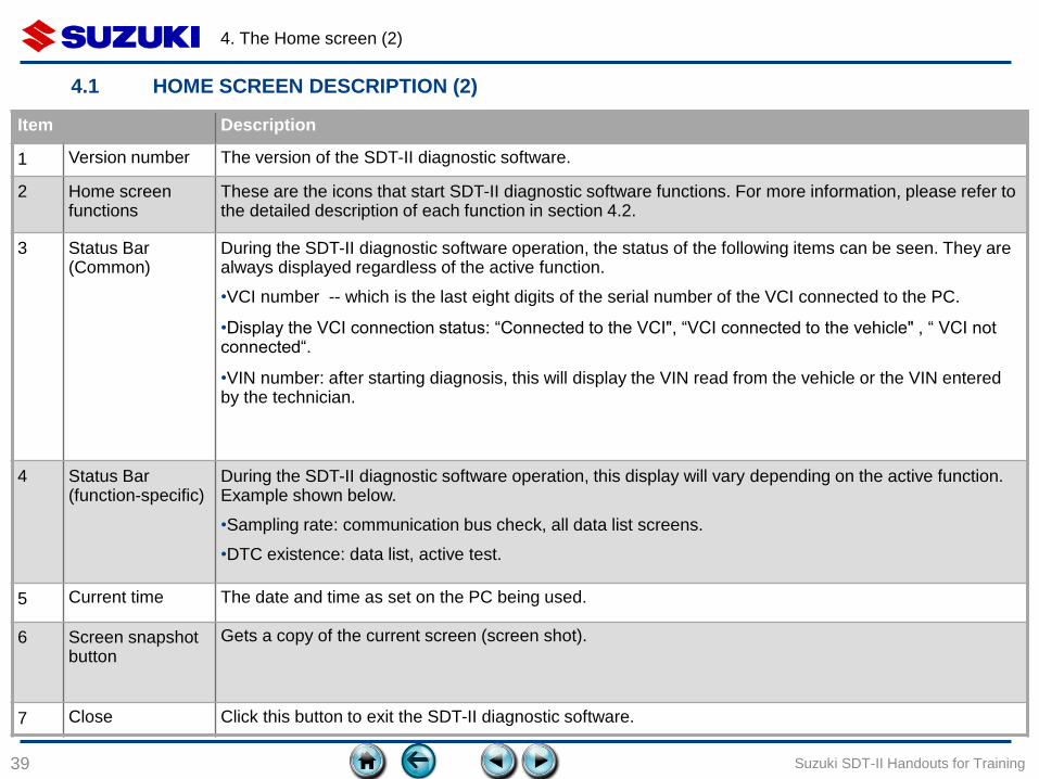
1 Version number The version of the SDT-II diagnostic software.
2 Home screen functions
These are the icons that start SDT-II diagnostic software functions. For more information, please refer to the detailed description of each function in section 4.2.
3 Status Bar (Common)
During the SDT-II diagnostic software operation, the status of the following items can be seen. They are always displayed regardless of the active function.
•VCI number -- which is the last eight digits of the serial number of the VCI connected to the PC.
•Display the VCI connection status: “Connected to the VCI", “VCI connected to the vehicle" , “ VCI not connected“.
•VIN number: after starting diagnosis, this will display the VIN read from the vehicle or the VIN entered by the technician.
4 Status Bar (function-specific)
During the SDT-II diagnostic software operation, this display will vary depending on the active function. Example shown below.
•Sampling rate: communication bus check, all data list screens.
•DTC existence: data list, active test.
5 Current time The date and time as set on the PC being used.
6 Screen snapshot button
Gets a copy of the current screen (screen shot).
7 Close Click this button to exit the SDT-II diagnostic software.
4.1 HOME SCREEN DESCRIPTION (2)

4. The Home screen (3)
40 Suzuki SDT-II Handouts for Training
4.2 ICON DESCRIPTIONS
Item Icon Description
1 Diagnosis
• Functions that perform vehicle diagnostics.
• Start communication with the vehicle by clicking this icon.
2 Save data
• Allows re-display of the collected diagnostic data.
• It has a search function by VIN number.
* More functions will be added in future SDT-II releases.
3 Tool
• Some functions like Error reporting will be added in future SDT-II
releases.
4 Configuration
• Language settings
• Units setting
• Shop and technician name setting
5 VCI setup
• Connect and disconnect the VCI.
• Configuration of VCI type.
6 Immobilizer
• This function is related to the Immobilizer.
7 Security device
• This function is related to the Security device.

4. The Home screen (4)
41 Suzuki SDT-II Handouts for Training
4.3 SYSTEM CONFIGURATION (1)
☞ Setting the units and the language of Suzuki SDT-II diagnostic software is done in System Configuration.
1
2 3
1. The default display language of SDT-II diagnostic software after installation is based on the Windows
OS default display language (in the case of English OS, the default setting is English). The default
units are set as "SI system" (km/h, km, kPa, ℃, etc.).
2. If you want to change the default setup, click the System Configuration icon on the Home screen to
see the system configuration screen. Select the desired language from the Languages & Destinations
drop-down list (1).
3. Once the language is selected, click the "OK" button (2) to be effective the change. The screen will
change to the selected language, and will return to the Home screen. If you click the "Cancel" button
(3) instead, the last language confirmed will be restored.
4. The Home screen (5)
42 Suzuki SDT-II Handouts for Training
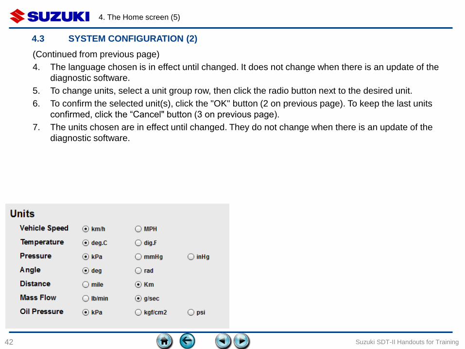
4.3 SYSTEM CONFIGURATION (2)
(Continued from previous page)
4. The language chosen is in effect until changed. It does not change when there is an update of the
diagnostic software.
5. To change units, select a unit group row, then click the radio button next to the desired unit.
6. To confirm the selected unit(s), click the "OK" button (2 on previous page). To keep the last units
confirmed, click the “Cancel" button (3 on previous page).
7. The units chosen are in effect until changed. They do not change when there is an update of the
diagnostic software.
4. The Home screen (7)
43
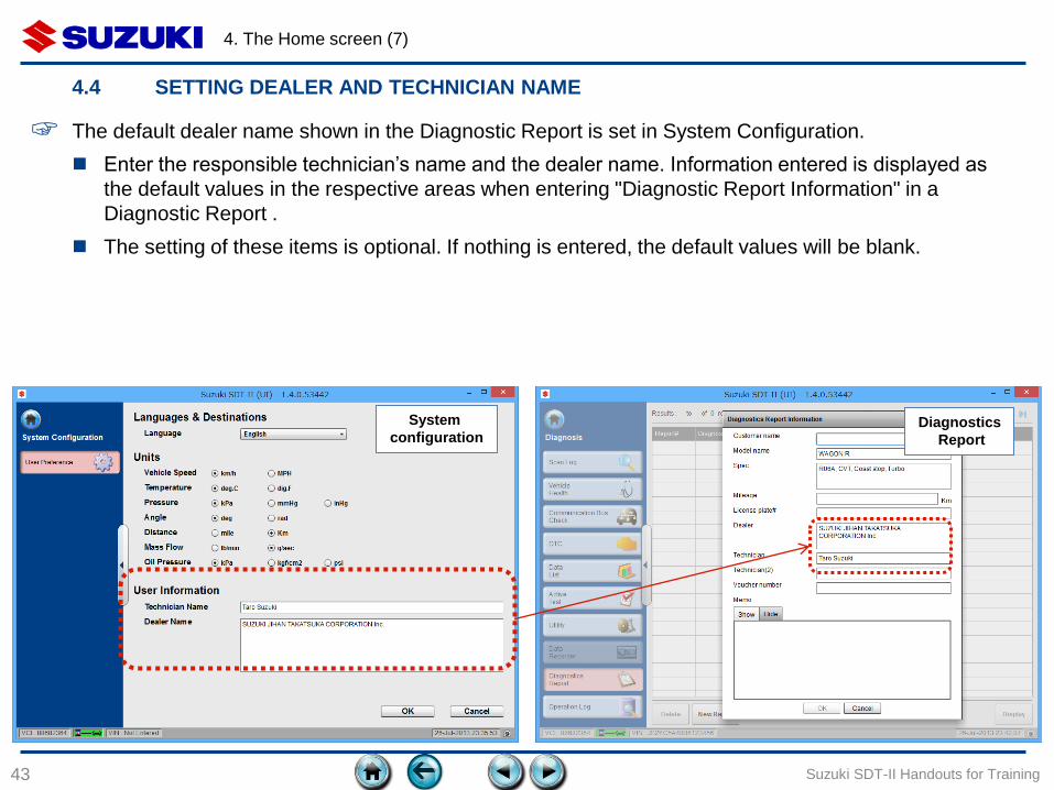
4.4 SETTING DEALER AND TECHNICIAN NAME
Suzuki SDT-II Handouts for Training
System
configuration
☞ The default dealer name shown in the Diagnostic Report is set in System Configuration.
Enter the responsible technician’s name and the dealer name. Information entered is displayed as
the default values in the respective areas when entering "Diagnostic Report Information" in a
Diagnostic Report .
The setting of these items is optional. If nothing is entered, the default values will be blank.
Diagnostics
Report
4. The Home screen (8)
44
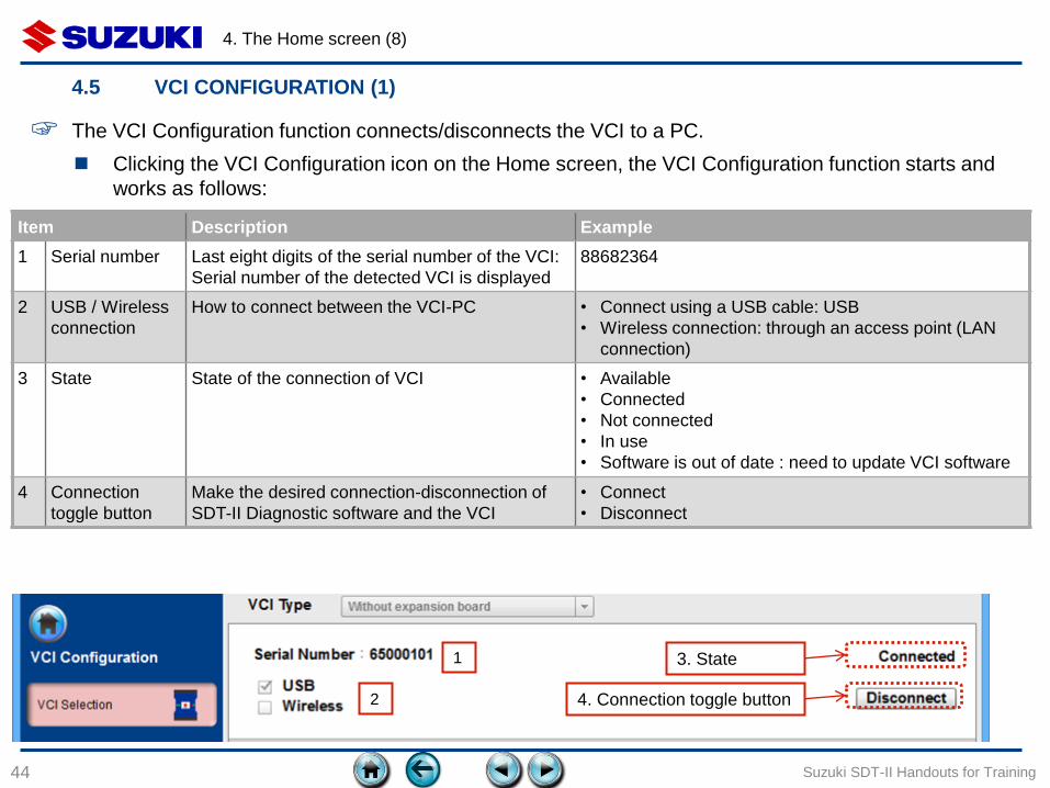
4.5 VCI CONFIGURATION (1)
Suzuki SDT-II Handouts for Training
3. State 1
2 4. Connection toggle button
Item Description Example
1 Serial number Last eight digits of the serial number of the VCI:
Serial number of the detected VCI is displayed
88682364
2 USB / Wireless
connection
How to connect between the VCI-PC • Connect using a USB cable: USB
• Wireless connection: through an access point (LAN
connection)
3 State State of the connection of VCI • Available
• Connected
• Not connected
• In use
• Software is out of date : need to update VCI software
4 Connection
toggle button
Make the desired connection-disconnection of
SDT-II Diagnostic software and the VCI
• Connect
• Disconnect
☞ The VCI Configuration function connects/disconnects the VCI to a PC.
Clicking the VCI Configuration icon on the Home screen, the VCI Configuration function starts and
works as follows:
4. The Home screen (9)
45 Suzuki SDT-II Handouts for Training
4.5 VCI CONFIGURATION (2)
Notes on VCI connecting and disconnecting.
To switch from USB to Wireless or vice-versa, click the “Disconnect” button (4), select the
method of selection (2), then click the “Connect” button (4). Wait a few seconds to be sure the
connection worked, then return to the Home screen.
4. The Home screen (10)
46 Suzuki SDT-II Handouts for Training
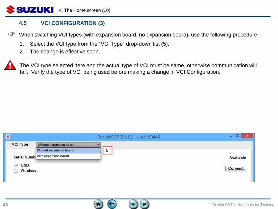
4.5 VCI CONFIGURATION (3)
☞ When switching VCI types (with expansion board, no expansion board), use the following procedure:
1. Select the VCI type from the “VCI Type” drop-down list (5).
2. The change is effective soon.
The VCI type selected here and the actual type of VCI must be same, otherwise communication will
fail. Verify the type of VCI being used before making a change in VCI Configuration.
5

Item Icon / Display Description
1 VCI serial number
Not connected to VCI
When connected, shows the last eight digits (88682364) of
the serial number.
2
VCI connection
state
Connected between the PC-VCI and between the VCI-
vehicle. Diagnosis can be started.
Connected between the PC-VCI, but not between the VCI-
vehicle. Cannot start diagnosis.
VCI not connected to PC. Cannot start diagnosis.
3 VIN VIN was not read from the ECU and was not entered into
the SDT-II Diagnostic program.
VCI is connected to a vehicle with VIN
JS2YC5A73A6300011.
4. The Home screen (11)
47 Suzuki SDT-II Handouts for Training
4.6 STATUS BAR DESCRIPTION

5. SCAN LOG
48 Suzuki SDT-II Handouts for Training
5.1 Overview of the Scan Log function
5.2 Buttons
5.3 VIN input/Confirmation
5.4 Option selection
5.5 VIN Registration
5. Scan log (1)
49
5.1 OVERVIEW OF THE SCAN LOG FUNCTION
Suzuki SDT-II Handouts for Training
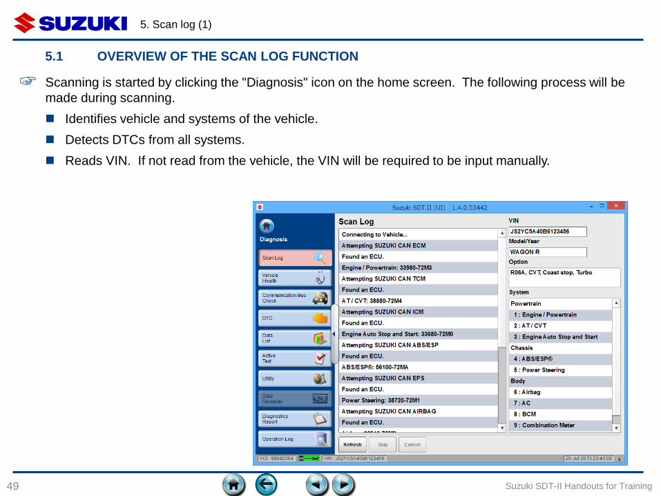
☞ Scanning is started by clicking the "Diagnosis" icon on the home screen. The following process will be
made during scanning.
Identifies vehicle and systems of the vehicle.
Detects DTCs from all systems.
Reads VIN. If not read from the vehicle, the VIN will be required to be input manually.

5. Scan log (2)
50
5.2 BUTTONS
Suzuki SDT-II Handouts for Training
Name of button Description
1 Refresh Redo scan log function again.
2 Skip Cancel the scanning to the system that
is now in progress, then start scanning
to the next system.
3 Cancel Cancel the scanning, and return to the
home screen.
1 2 3
5. Scan log (3)
51
5.3 VIN INPUT/CONFIRMATION (1)
Suzuki SDT-II Handouts for Training
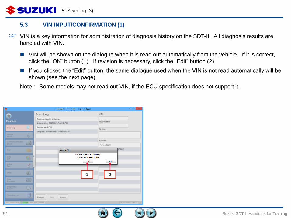
☞ VIN is a key information for administration of diagnosis history on the SDT-II. All diagnosis results are
handled with VIN.
VIN will be shown on the dialogue when it is read out automatically from the vehicle. If it is correct,
click the “OK” button (1). If revision is necessary, click the “Edit” button (2).
If you clicked the “Edit” button, the same dialogue used when the VIN is not read automatically will be
shown (see the next page).
Note : Some models may not read out VIN, if the ECU specification does not support it.
1 2
5. Scan log (4)
52
5.3 VIN INPUT/CONFIRMATION (2)
Suzuki SDT-II Handouts for Training
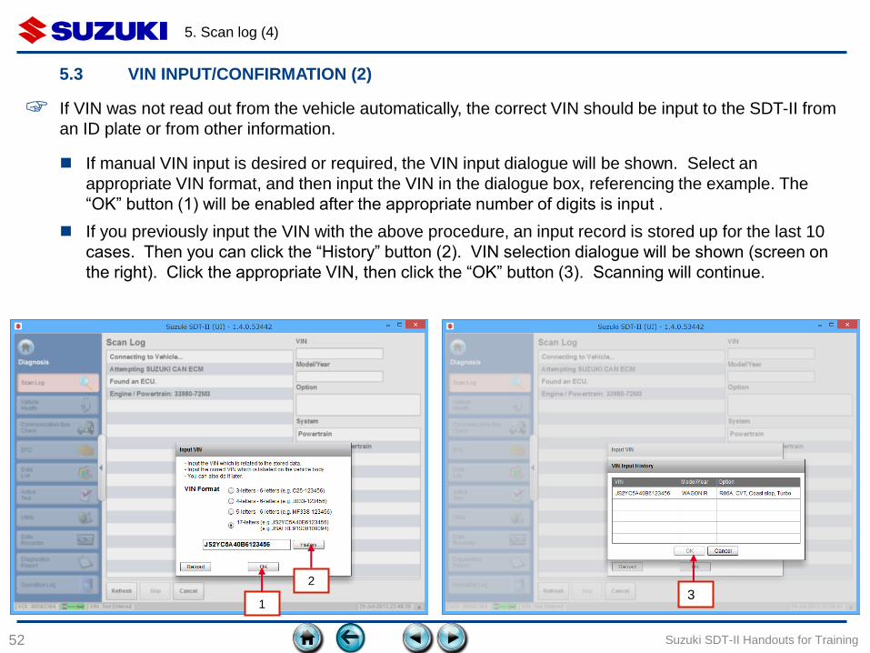
If manual VIN input is desired or required, the VIN input dialogue will be shown. Select an
appropriate VIN format, and then input the VIN in the dialogue box, referencing the example. The
“OK” button (1) will be enabled after the appropriate number of digits is input .
If you previously input the VIN with the above procedure, an input record is stored up for the last 10
cases. Then you can click the “History” button (2). VIN selection dialogue will be shown (screen on
the right). Click the appropriate VIN, then click the “OK” button (3). Scanning will continue.
☞ If VIN was not read out from the vehicle automatically, the correct VIN should be input to the SDT-II from
an ID plate or from other information.
3 1
2
5. Scan log (5)
53
5.4 OPTION SELECTION
Suzuki SDT-II Handouts for Training
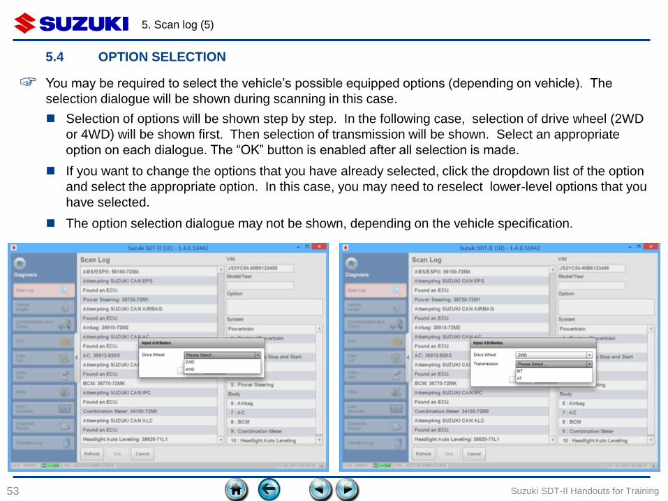
☞ You may be required to select the vehicle’s possible equipped options (depending on vehicle). The
selection dialogue will be shown during scanning in this case.
Selection of options will be shown step by step. In the following case, selection of drive wheel (2WD
or 4WD) will be shown first. Then selection of transmission will be shown. Select an appropriate
option on each dialogue. The “OK” button is enabled after all selection is made.
If you want to change the options that you have already selected, click the dropdown list of the option
and select the appropriate option. In this case, you may need to reselect lower-level options that you
have selected.
The option selection dialogue may not be shown, depending on the vehicle specification.
5. Scan log (6)
54
5.5 VIN REGISTRATION
Suzuki SDT-II Handouts for Training
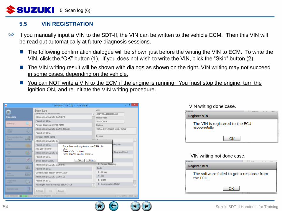
☞ If you manually input a VIN to the SDT-II, the VIN can be written to the vehicle ECM. Then this VIN will
be read out automatically at future diagnosis sessions.
The following confirmation dialogue will be shown just before the writing the VIN to ECM. To write the
VIN, click the “OK” button (1). If you does not wish to write the VIN, click the “Skip” button (2).
The VIN writing result will be shown with dialogs as shown on the right. VIN writing may not succeed
in some cases, depending on the vehicle.
You can NOT write a VIN to the ECM if the engine is running. You must stop the engine, turn the
ignition ON, and re-initiate the VIN writing procedure.
VIN writing done case.
1 2
VIN writing not done case.
6. COMMON DIAGNOSIS FUNCTIONS
55
6.1 Common diagnosis functions
6.2 Folding of the menu bar
Suzuki SDT-II Handouts for Training

6. Common diagnosis functions (1)
56
6.1 COMMON DIAGNOSIS FUNCTIONS
Suzuki SDT-II Handouts for Training
Link Buttons
Menu buttons
Move to the Home screen
6. Common diagnosis functions (2)
57
6.2 FOLDING OF THE MENU BAR
Suzuki SDT-II Handouts for Training
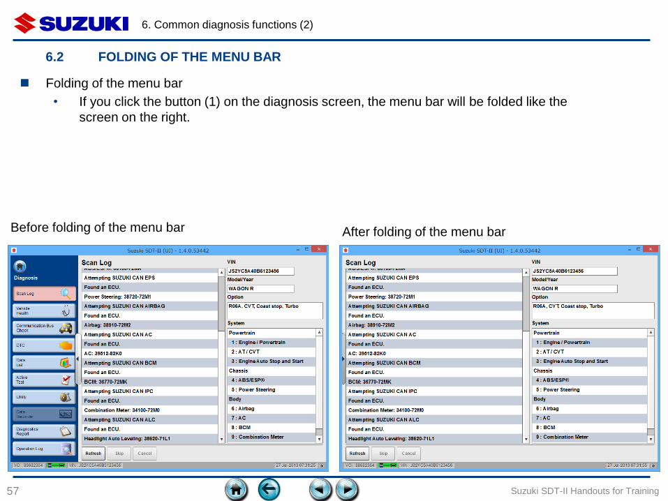
Folding of the menu bar
• If you click the button (1) on the diagnosis screen, the menu bar will be folded like the
screen on the right.
1
Before folding of the menu bar After folding of the menu bar
7. VEHICLE HEALTH
58
7.1 Items on Vehicle Health function
7.2 Buttons
Suzuki SDT-II Handouts for Training
7. Vehicle health (1)
59
7.1 ITEMS ON VEHICLE HEALTH FUNCTION (1)
Suzuki SDT-II Handouts for Training
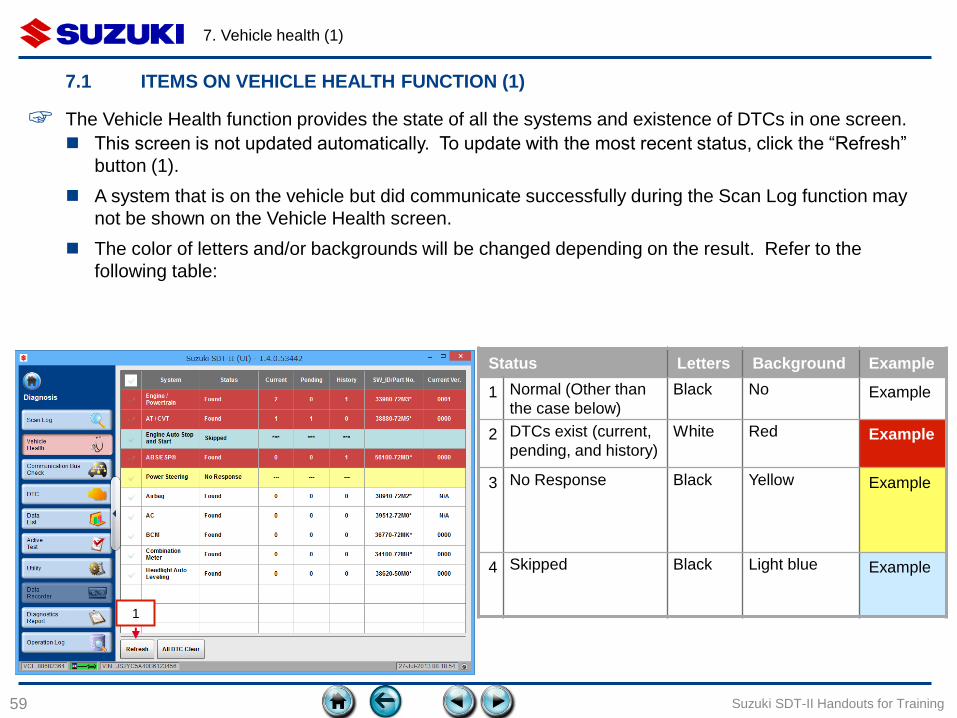
☞ The Vehicle Health function provides the state of all the systems and existence of DTCs in one screen.
Status Letters Background Example
1 Normal (Other than
the case below)
Black No Example
2 DTCs exist (current,
pending, and history)
White Red Example
3 No Response Black Yellow Example
4 Skipped Black Light blue Example
This screen is not updated automatically. To update with the most recent status, click the “Refresh”
button (1).
A system that is on the vehicle but did communicate successfully during the Scan Log function may
not be shown on the Vehicle Health screen.
The color of letters and/or backgrounds will be changed depending on the result. Refer to the
following table:
1
7. Vehicle health (2)
60
7.1 ITEMS ON VEHICLE HEALTH FUNCTION (2) – SYSTEM SELECTION
Suzuki SDT-II Handouts for Training
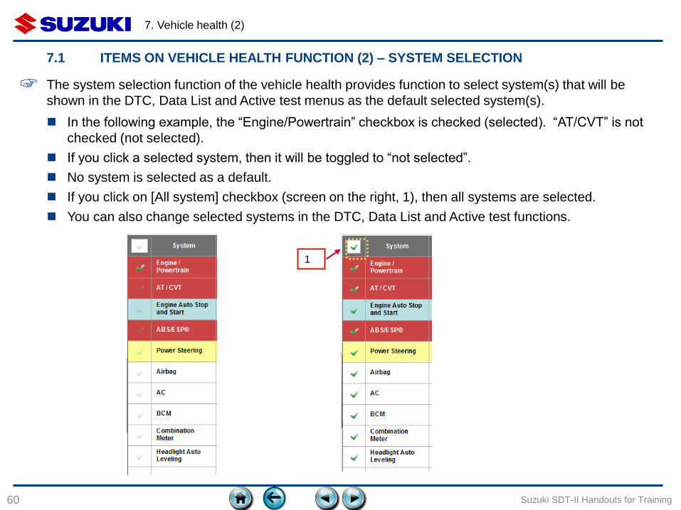
☞ The system selection function of the vehicle health provides function to select system(s) that will be
shown in the DTC, Data List and Active test menus as the default selected system(s).
1
In the following example, the “Engine/Powertrain” checkbox is checked (selected). “AT/CVT” is not
checked (not selected).
If you click a selected system, then it will be toggled to “not selected”.
No system is selected as a default.
If you click on [All system] checkbox (screen on the right, 1), then all systems are selected.
You can also change selected systems in the DTC, Data List and Active test functions.
7. Vehicle health (3)
61
7.1 ITEMS ON VEHICLE HEALTH FUNCTION (3) – STATUS
Suzuki SDT-II Handouts for Training
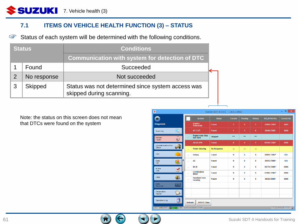
Status Conditions
Communication with system for detection of DTC
1 Found Succeeded
2 No response Not succeeded
3 Skipped Status was not determined since system access was
skipped during scanning.
☞ Status of each system will be determined with the following conditions.
Note: the status on this screen does not mean
that DTCs were found on the system
7. Vehicle health (4)
62
7.1 ITEMS ON VEHICLE HEALTH FUNCTION (3) – DTC AND SOFTWARE ID/VERSION
Suzuki SDT-II Handouts for Training
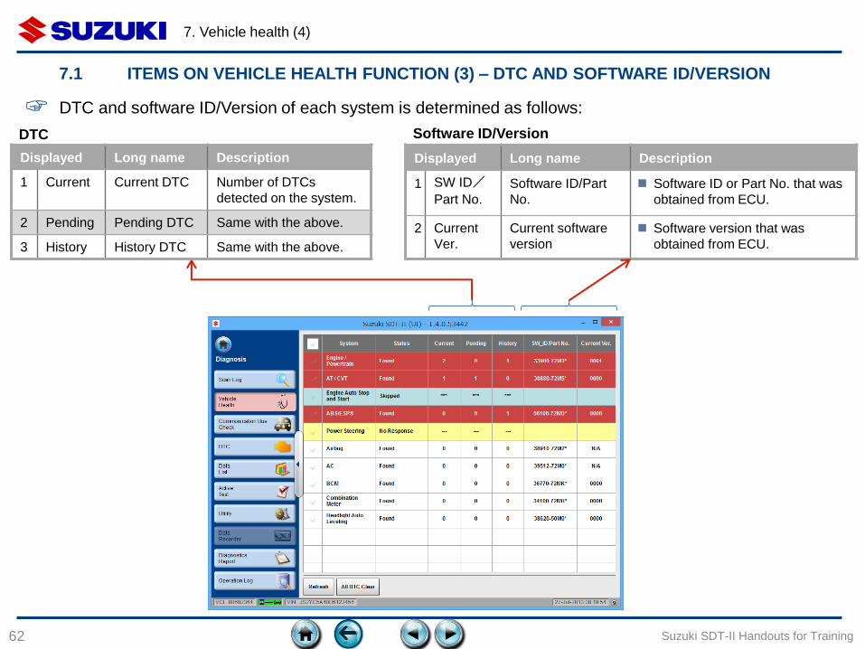
Displayed Long name Description
1 Current Current DTC Number of DTCs
detected on the system.
2 Pending Pending DTC Same with the above.
3 History History DTC Same with the above.
Displayed Long name Description
1 SW ID/
Part No.
Software ID/Part
No.
Software ID or Part No. that was
obtained from ECU.
2 Current
Ver.
Current software
version
Software version that was
obtained from ECU.
DTC Software ID/Version
☞ DTC and software ID/Version of each system is determined as follows:
7. Vehicle health (5)
63
7.2 BUTTONS (1)
Suzuki SDT-II Handouts for Training
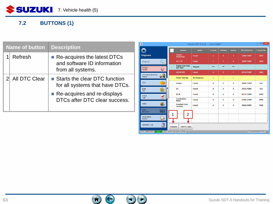
Name of button Description
1 Refresh Re-acquires the latest DTCs
and software ID information
from all systems.
2 All DTC Clear Starts the clear DTC function
for all systems that have DTCs.
Re-acquires and re-displays
DTCs after DTC clear success.
1 2
7. Vehicle health (6)
64
7.2 BUTTONS (2) – ALL DTC CLEAR
Suzuki SDT-II Handouts for Training
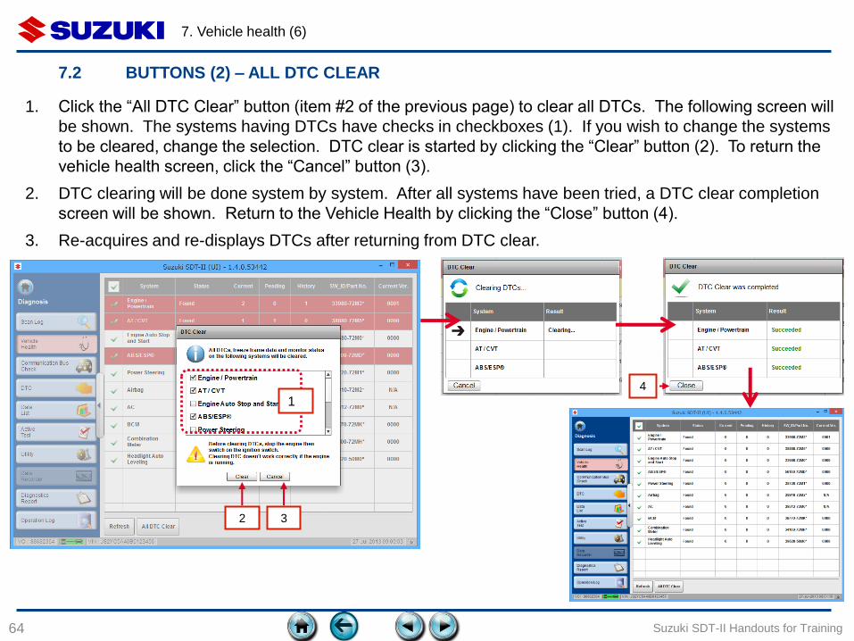
1. Click the “All DTC Clear” button (item #2 of the previous page) to clear all DTCs. The following screen will
be shown. The systems having DTCs have checks in checkboxes (1). If you wish to change the systems
to be cleared, change the selection. DTC clear is started by clicking the “Clear” button (2). To return the
vehicle health screen, click the “Cancel” button (3).
2. DTC clearing will be done system by system. After all systems have been tried, a DTC clear completion
screen will be shown. Return to the Vehicle Health by clicking the “Close” button (4).
3. Re-acquires and re-displays DTCs after returning from DTC clear.
1
4
2 3
8. COMMUNICATION BUS CHECK
65
8.1 Items on Communication Bus Check function
Suzuki SDT-II Handouts for Training
8. Communication Bus check (1)
66
8.1 ITEMS ON COMMUNICATION BUS CHECK FUNCTION
Suzuki SDT-II Handouts for Training
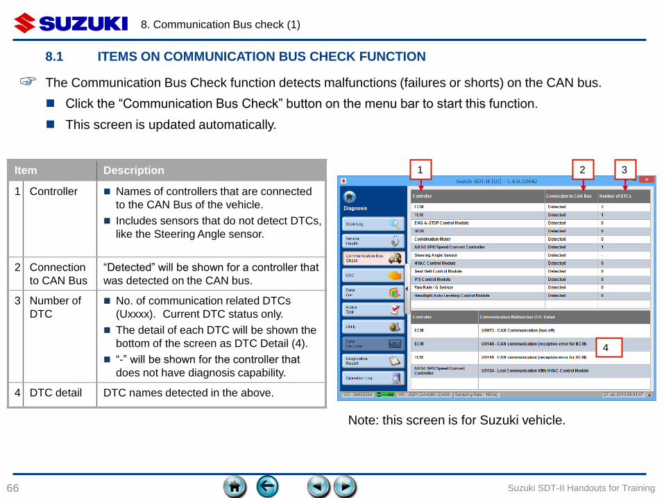
Item Description
1 Controller Names of controllers that are connected
to the CAN Bus of the vehicle.
Includes sensors that do not detect DTCs,
like the Steering Angle sensor.
2 Connection
to CAN Bus
“Detected” will be shown for a controller that
was detected on the CAN bus.
3 Number of
DTC
No. of communication related DTCs
(Uxxxx). Current DTC status only.
The detail of each DTC will be shown the
bottom of the screen as DTC Detail (4).
“-” will be shown for the controller that
does not have diagnosis capability.
4 DTC detail DTC names detected in the above.
4
Note: this screen is for Suzuki vehicle.
1 2 3
☞ The Communication Bus Check function detects malfunctions (failures or shorts) on the CAN bus.
Click the “Communication Bus Check” button on the menu bar to start this function.
This screen is updated automatically.

9. DTC
67
9.1 Items on DTC function
9.2 Buttons
Suzuki SDT-II Handouts for Training

9. DTC (1)
68
9.1 ITEMS ON DTC FUNCTION (1)
Suzuki SDT-II Handouts for Training
☞ The DTC function provides detection, display and clear functions for DTC and Freeze Frame data.
2 3 4 5 6 7
1
8 9
Click the “DTC” button on the menu bar to start this function.
See the following page for the description of each item.
This screen is updated automatically.
9. DTC (2)
69
9.1 ITEMS ON DTC FUNCTION (2)
Suzuki SDT-II Handouts for Training
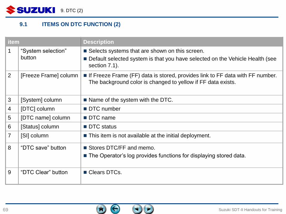
item Description
1 “System selection”
button
Selects systems that are shown on this screen.
Default selected system is that you have selected on the Vehicle Health (see
section 7.1).
2 [Freeze Frame] column If Freeze Frame (FF) data is stored, provides link to FF data with FF number.
The background color is changed to yellow if FF data exists.
3 [System] column Name of the system with the DTC.
4 [DTC] column DTC number
5 [DTC name] column DTC name
6 [Status] column DTC status
7 [SI] column This item is not available at the initial deployment.
8 “DTC save” button Stores DTC/FF and memo.
The Operator’s log provides functions for displaying stored data.
9 “DTC Clear” button Clears DTCs.

9. DTC (3)
70 Suzuki SDT-II Handouts for Training
If no DTCs exist on the systems that are selected on the Vehicle Health or DTC function, a message
“No DTCs Found” will be shown.
If DTCs were found on any systems that were not selected, the same message will be shown.
If no systems were selected on the Vehicle Health or DTC function, ‘No Systems Selected’ will be
displayed. Select a system to display DTCs (see next page).
9.1 ITEMS ON DTC FUNCTION (3)
9. DTC (4)
71
9.2 BUTTONS (1) – SYSTEM SELECTION
Suzuki SDT-II Handouts for Training
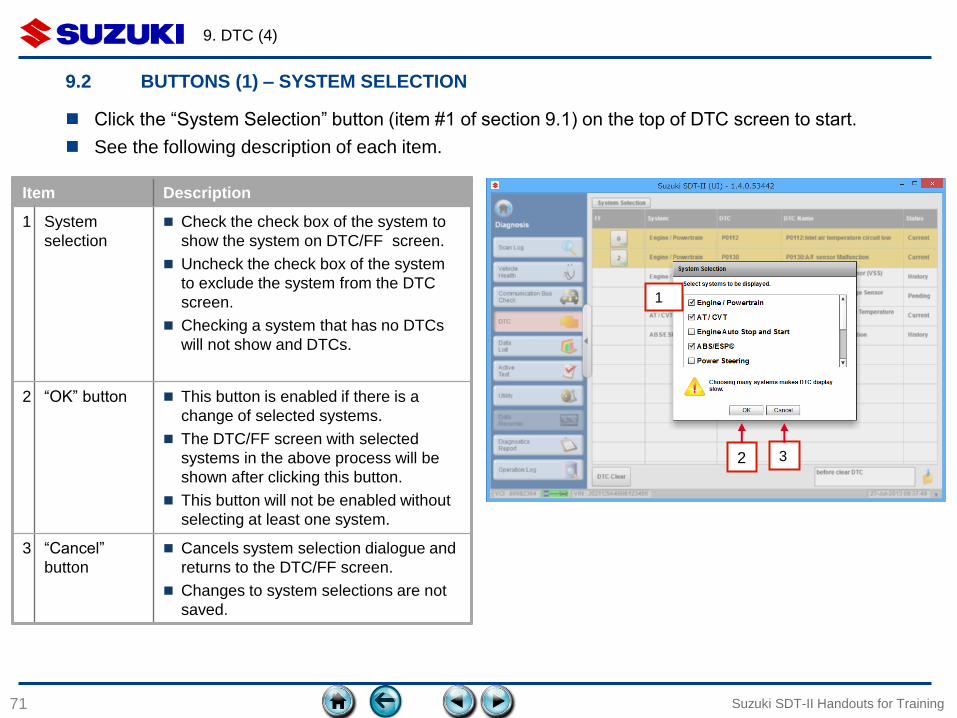
Item Description
1 System
selection
Check the check box of the system to
show the system on DTC/FF screen.
Uncheck the check box of the system
to exclude the system from the DTC
screen.
Checking a system that has no DTCs
will not show and DTCs.
2 “OK” button This button is enabled if there is a
change of selected systems.
The DTC/FF screen with selected
systems in the above process will be
shown after clicking this button.
This button will not be enabled without
selecting at least one system.
3 “Cancel”
button
Cancels system selection dialogue and
returns to the DTC/FF screen.
Changes to system selections are not
saved.
1
2 3
Click the “System Selection” button (item #1 of section 9.1) on the top of DTC screen to start.
See the following description of each item.

9. DTC (5)
72
9.2 BUTTONS (2) – FREEZE FRAME
Suzuki SDT-II Handouts for Training
4 5 6
7
2 1
3
Item Description
1 System Name of system for which FF
data was recorded.
2 Frame ID Frame ID of the FF data.
3 DTC/DTC name DTC number and name for which
FF data was recorded.
4 [Parameter]
column
Name of parameters that were
recorded as FF data.
5 [value] column Value of parameters that were
recorded as FF data.
6 [unit] column Unit of parameter values that
were recorded as FF data.
7 “Close” button Close the window.
Click “FF” button (item #2 of section 9.1) to start this function.
Each FF Data will be shown in the each separate window. One or more FF screens can be shown at a
time.
This screen is static and is not updated automatically or manually.
9. DTC (6)
73
9.2 BUTTONS (3) – DTC SAVE
Suzuki SDT-II Handouts for Training
1
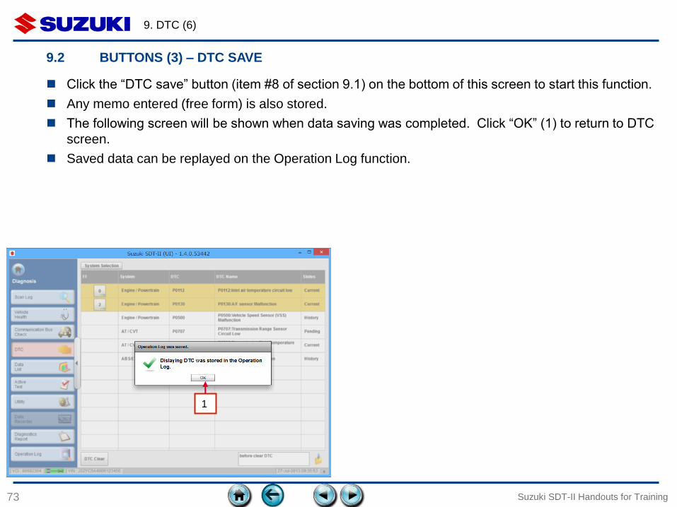
Click the “DTC save” button (item #8 of section 9.1) on the bottom of this screen to start this function.
Any memo entered (free form) is also stored.
The following screen will be shown when data saving was completed. Click “OK” (1) to return to DTC
screen.
Saved data can be replayed on the Operation Log function.
9. DTC (7)
74 Suzuki SDT-II Handouts for Training
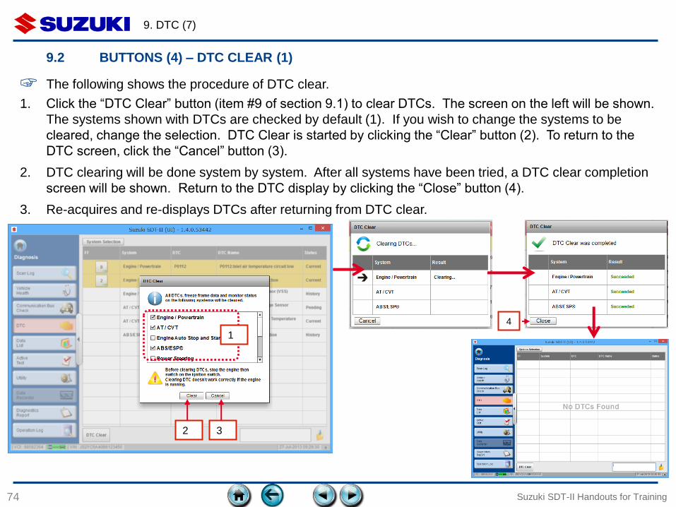
☞ The following shows the procedure of DTC clear.
1
2 3
4
9.2 BUTTONS (4) – DTC CLEAR (1)
1. Click the “DTC Clear” button (item #9 of section 9.1) to clear DTCs. The screen on the left will be shown.
The systems shown with DTCs are checked by default (1). If you wish to change the systems to be
cleared, change the selection. DTC Clear is started by clicking the “Clear” button (2). To return to the
DTC screen, click the “Cancel” button (3).
2. DTC clearing will be done system by system. After all systems have been tried, a DTC clear completion
screen will be shown. Return to the DTC display by clicking the “Close” button (4).
3. Re-acquires and re-displays DTCs after returning from DTC clear.
9. DTC (8)
75 Suzuki SDT-II Handouts for Training
3
1 2
4 5
9.2 BUTTONS (4) – DTC CLEAR (2)
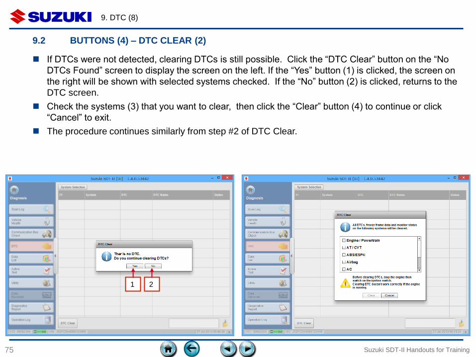
If DTCs were not detected, clearing DTCs is still possible. Click the “DTC Clear” button on the “No
DTCs Found” screen to display the screen on the left. If the “Yes” button (1) is clicked, the screen on
the right will be shown with selected systems checked. If the “No” button (2) is clicked, returns to the
DTC screen.
Check the systems (3) that you want to clear, then click the “Clear” button (4) to continue or click
“Cancel” to exit.
The procedure continues similarly from step #2 of DTC Clear.
10. SAVED DATA
76
10.1 Overview
10.2 Items of saved data
10.3 Basic Operation
Suzuki SDT-II Handouts for Training

10. Saved data (1)
77 Suzuki SDT-II Handouts for Training
10.1 OVERVIEW
The following shows the scope of saved data at initial deployment of the SDT-II application.
Type Description Note
a. DTC/Freeze Frame
data
• DTC data, when the “DTC Save” button
is clicked.
See section 9.2 (3) for data
saving procedure.
b. Snapshot data • Snapshot data that was stored by the
function automatically or manually.
See section 11.5 for data
saving procedure.
☞ The SDT-II provides an “Operation Log” function that handles various saved data stored during diagnosis.
Type Menu Scope of data
a. Operation Log
during
diagnosis
Diagnosis >
Operation Log
• Operation log for the current vehicle in diagnosis. Includes
currently and previously saved data for this vehicle.
b. Operation Log
of saved data
Review Saved
Data >
Operation Log
• Operation log that was stored on the PC currently in use.
• Operation log that was stored on another PC and was imported
to the PC currently in use.
This function is provided through the following two menus due to their difference of the scope.
10. Saved data (2)
78 Suzuki SDT-II Handouts for Training
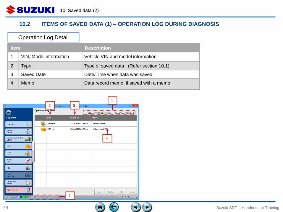
10.2 ITEMS OF SAVED DATA (1) – OPERATION LOG DURING DIAGNOSIS
Item Description
1 VIN, Model information Vehicle VIN and model information.
2 Type Type of saved data. (Refer section 10.1)
3 Saved Date Date/Time when data was saved.
4 Memo Data record memo, if saved with a memo.
1
2
1
3
4
Operation Log Detail
10. Saved data (3)
79 Suzuki SDT-II Handouts for Training
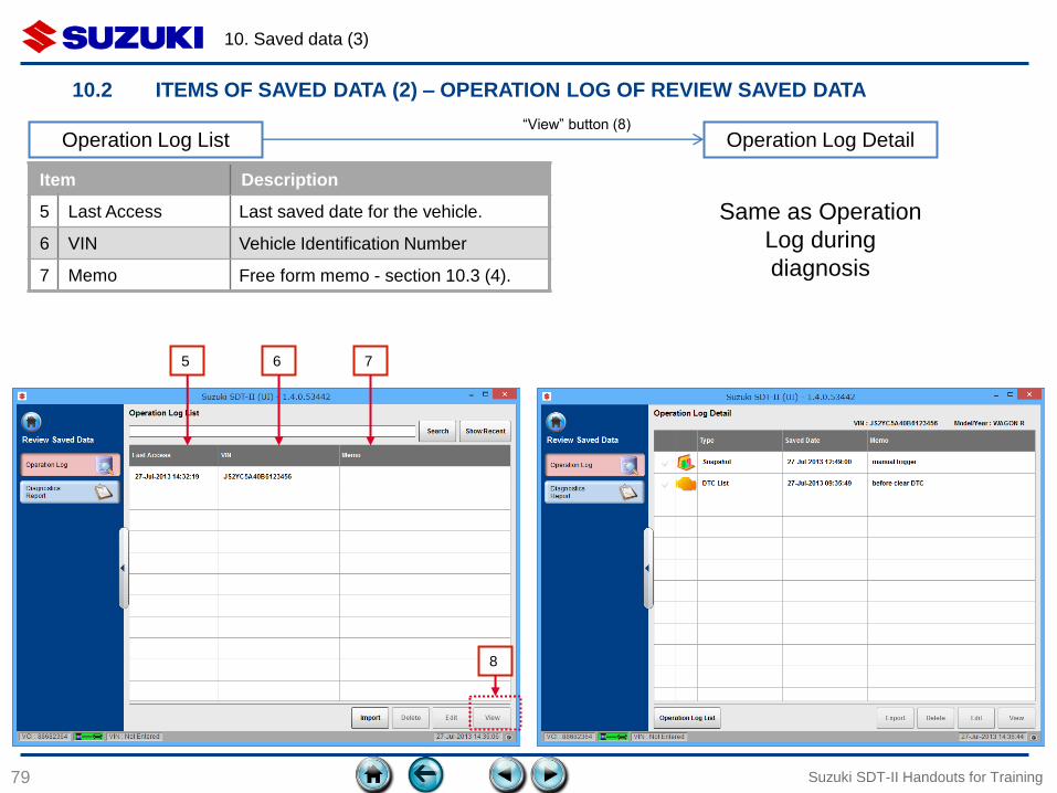
10.2 ITEMS OF SAVED DATA (2) – OPERATION LOG OF REVIEW SAVED DATA
Item Description
5 Last Access Last saved date for the vehicle.
6 VIN Vehicle Identification Number
7 Memo Free form memo - section 10.3 (4).
Operation Log List
7
Operation Log Detail
5 6
Same as Operation
Log during
diagnosis
“View” button (8)
8
10. Saved data (4)
80 Suzuki SDT-II Handouts for Training
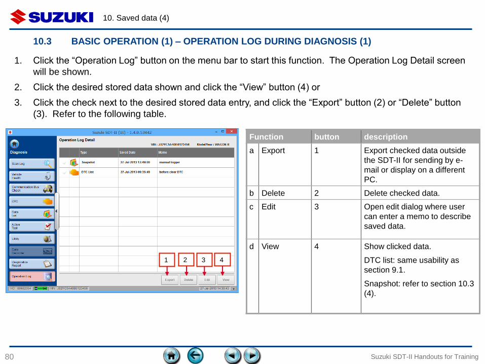
10.3 BASIC OPERATION (1) – OPERATION LOG DURING DIAGNOSIS (1)
3 1 2
Function button description
a Export 1 Export checked data outside
the SDT-II for sending by e-
mail or display on a different
PC.
b Delete 2 Delete checked data.
c Edit 3 Open edit dialog where user
can enter a memo to describe
saved data.
d View 4 Show clicked data.
DTC list: same usability as
section 9.1.
Snapshot: refer to section 10.3
(4).
1. Click the “Operation Log” button on the menu bar to start this function. The Operation Log Detail screen
will be shown.
2. Click the desired stored data shown and click the “View” button (4) or
3. Click the check next to the desired stored data entry, and click the “Export” button (2) or “Delete” button
(3). Refer to the following table.
4
10. Saved data (5)
81 Suzuki SDT-II Handouts for Training
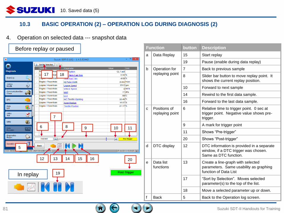
4. Operation on selected data --- snapshot data
12
5
6 8 10
7
9 11
13 14 15 16
Function button Description
a Data Replay 15 Start replay
19 Pause (enable during data replay)
b Operation for
replaying point
7 Back to previous sample
8 Slider bar button to move replay point. It
shows the current replay position.
10 Forward to next sample
14 Rewind to the first data sample.
16 Forward to the last data sample.
c Positions of
replaying point
6 Relative time to trigger point. 0 sec at
trigger point. Negative value shows pre-
trigger.
9 A mark for trigger point
11 Shows “Pre-trigger”
20 Shows “Post-trigger”
d DTC display 12 DTC information is provided in a separate
window, if a DTC trigger was chosen.
Same as DTC function.
e Data list
functions
13 Create a line-graph with selected
parameters. Same usability as graphing
function of Data List
17 “Sort by Selection”. Moves selected
parameter(s) to the top of the list.
18 Move a selected parameter up or down.
f Back 5 Back to the Operation log screen.
17 18
19 In replay
Before replay or paused
20
10.3 BASIC OPERATION (2) – OPERATION LOG DURING DIAGNOSIS (2)
10. Saved data (6)
82 Suzuki SDT-II Handouts for Training
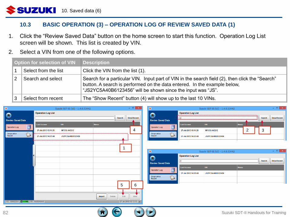
1
2 3 4
Option for selection of VIN Description
1 Select from the list Click the VIN from the list (1).
2 Search and select Search for a particular VIN. Input part of VIN in the search field (2), then click the “Search”
button. A search is performed on the data entered. In the example below,
“JS2YC5A40B6123456” will be shown since the input was “JS”.
3 Select from recent The “Show Recent” button (4) will show up to the last 10 VINs.
5 6
10.3 BASIC OPERATION (3) – OPERATION LOG OF REVIEW SAVED DATA (1)
1. Click the “Review Saved Data” button on the home screen to start this function. Operation Log List
screen will be shown. This list is created by VIN.
2. Select a VIN from one of the following options.
10. Saved data (7)
83 Suzuki SDT-II Handouts for Training
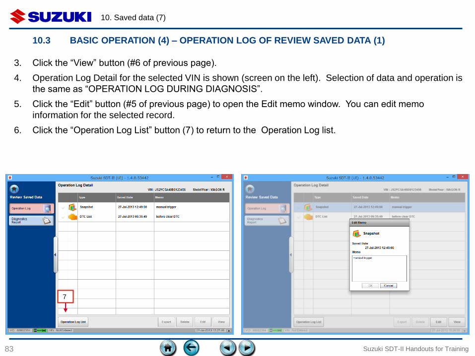
3. Click the “View” button (#6 of previous page).
4. Operation Log Detail for the selected VIN is shown (screen on the left). Selection of data and operation is
the same as “OPERATION LOG DURING DIAGNOSIS”.
5. Click the “Edit” button (#5 of previous page) to open the Edit memo window. You can edit memo
information for the selected record.
6. Click the “Operation Log List” button (7) to return to the Operation Log list.
7
10.3 BASIC OPERATION (4) – OPERATION LOG OF REVIEW SAVED DATA (1)
10. Saved data (8)
84 Suzuki SDT-II Handouts for Training
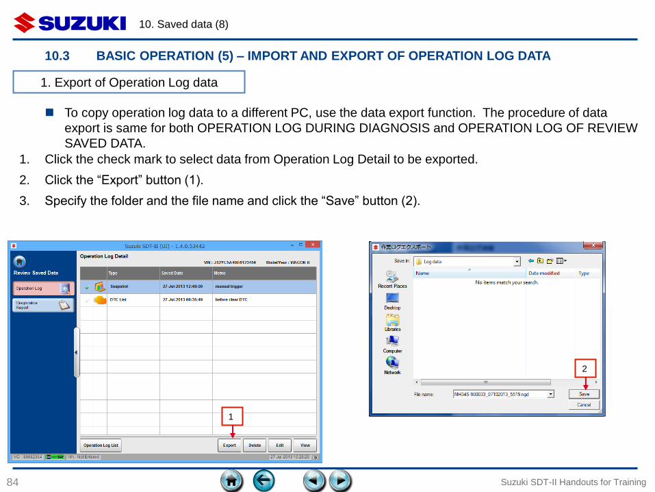
1. Export of Operation Log data
1
2
10.3 BASIC OPERATION (5) – IMPORT AND EXPORT OF OPERATION LOG DATA
To copy operation log data to a different PC, use the data export function. The procedure of data
export is same for both OPERATION LOG DURING DIAGNOSIS and OPERATION LOG OF REVIEW
SAVED DATA.
1. Click the check mark to select data from Operation Log Detail to be exported.
2. Click the “Export” button (1).
3. Specify the folder and the file name and click the “Save” button (2).
10. Saved data (9)
85 Suzuki SDT-II Handouts for Training
3
4
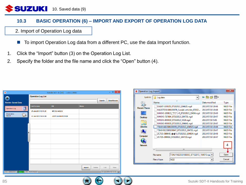
10.3 BASIC OPERATION (6) – IMPORT AND EXPORT OF OPERATION LOG DATA
2. Import of Operation Log data
To import Operation Log data from a different PC, use the data Import function.
1. Click the “Import” button (3) on the Operation Log List.
2. Specify the folder and the file name and click the “Open” button (4).
10. Saved data (10)
86 Suzuki SDT-II Handouts for Training
5
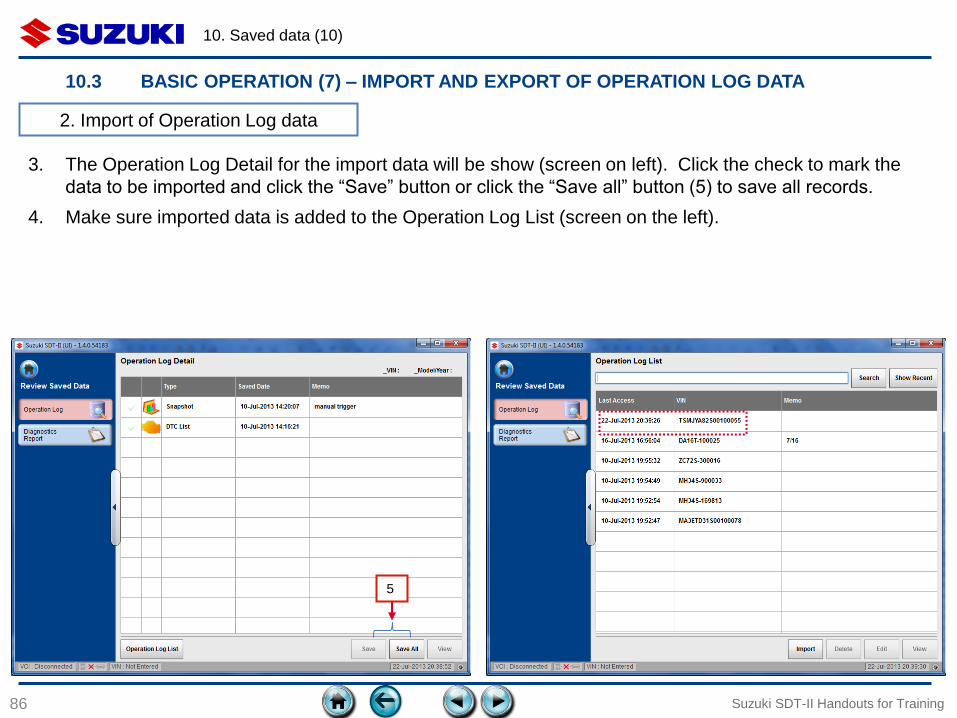
10.3 BASIC OPERATION (7) – IMPORT AND EXPORT OF OPERATION LOG DATA
2. Import of Operation Log data
3. The Operation Log Detail for the import data will be show (screen on left). Click the check to mark the
data to be imported and click the “Save” button or click the “Save all” button (5) to save all records.
4. Make sure imported data is added to the Operation Log List (screen on the left).

11. DATA LIST
(GENERAL FUNCTIONS)
87
11.1 Items of Data List
11.2 Buttons
11.3 Predefined List
11.4 Custom List
11.5 Snapshot
Suzuki SDT-II Handouts for Training
11. Data list (General functions) (1)
88
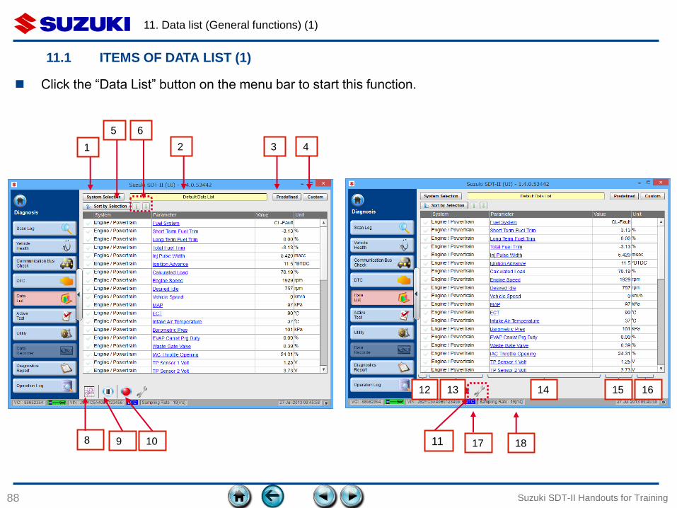
11.1 ITEMS OF DATA LIST (1)
Suzuki SDT-II Handouts for Training
1 3 4
5 6
2
8 9 10
Click the “Data List” button on the menu bar to start this function.
12 13 14 15 16
17 18 11
11. Data list (General functions) (2)
89 Suzuki SDT-II Handouts for Training
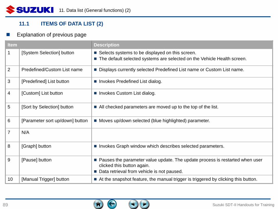
Item Description
1 [System Selection] button Selects systems to be displayed on this screen.
The default selected systems are selected on the Vehicle Health screen.
2 Predefined/Custom List name Displays currently selected Predefined List name or Custom List name.
3 [Predefined] List button Invokes Predefined List dialog.
4 [Custom] List button Invokes Custom List dialog.
5 [Sort by Selection] button All checked parameters are moved up to the top of the list.
6 [Parameter sort up/down] button Moves up/down selected (blue highlighted) parameter.
7 N/A
8 [Graph] button Invokes Graph window which describes selected parameters.
9 [Pause] button Pauses the parameter value update. The update process is restarted when user
clicked this button again.
Data retrieval from vehicle is not paused.
10 [Manual Trigger] button At the snapshot feature, the manual trigger is triggered by clicking this button.
Explanation of previous page
11.1 ITEMS OF DATA LIST (2)
11. Data list (General functions) (3)
90
11.1 ITEMS OF DATA LIST (3)
Suzuki SDT-II Handouts for Training
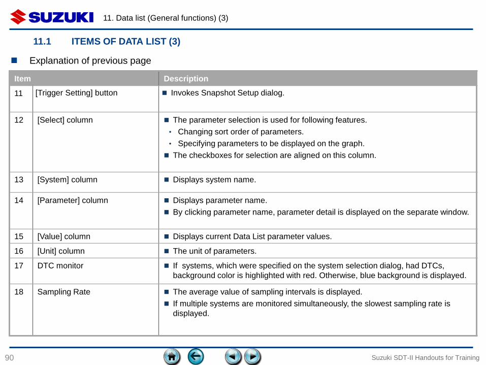
Item Description
11 [Trigger Setting] button Invokes Snapshot Setup dialog.
12 [Select] column The parameter selection is used for following features.
• Changing sort order of parameters.
• Specifying parameters to be displayed on the graph.
The checkboxes for selection are aligned on this column.
13 [System] column Displays system name.
14 [Parameter] column Displays parameter name.
By clicking parameter name, parameter detail is displayed on the separate window.
15 [Value] column Displays current Data List parameter values.
16 [Unit] column The unit of parameters.
17 DTC monitor If systems, which were specified on the system selection dialog, had DTCs,
background color is highlighted with red. Otherwise, blue background is displayed.
18 Sampling Rate The average value of sampling intervals is displayed.
If multiple systems are monitored simultaneously, the slowest sampling rate is
displayed.
Explanation of previous page
11. Data list (General functions) (4)
91 Suzuki SDT-II Handouts for Training
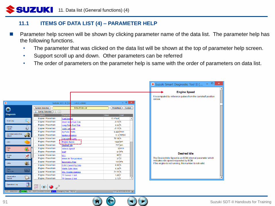
Parameter help screen will be shown by clicking parameter name of the data list. The parameter help has
the following functions.
• The parameter that was clicked on the data list will be shown at the top of parameter help screen.
• Support scroll up and down. Other parameters can be referred
• The order of parameters on the parameter help is same with the order of parameters on data list.
11.1 ITEMS OF DATA LIST (4) – PARAMETER HELP
11. Data list (General functions) (5)
92
11.2 BUTTONS (1) – SYSTEM SELECTION
Suzuki SDT-II Handouts for Training
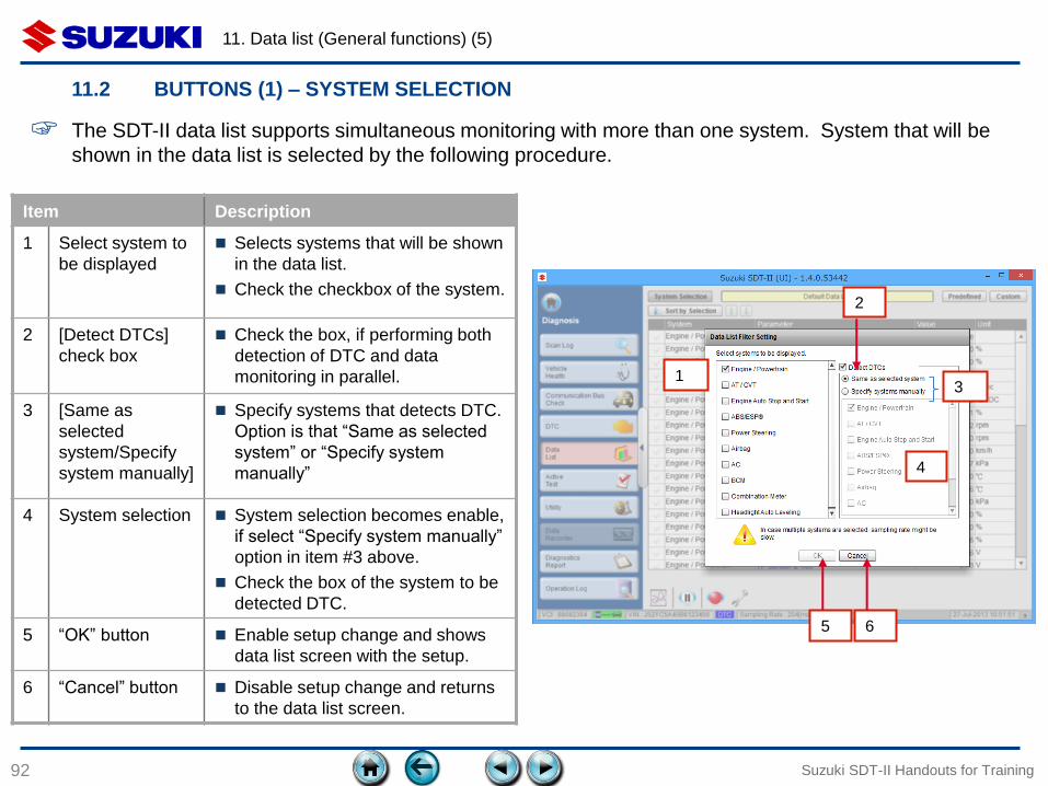
Item Description
1 Select system to
be displayed
Selects systems that will be shown
in the data list.
Check the checkbox of the system.
2 [Detect DTCs]
check box
Check the box, if performing both
detection of DTC and data
monitoring in parallel.
3 [Same as
selected
system/Specify
system manually]
Specify systems that detects DTC.
Option is that “Same as selected
system” or “Specify system
manually”
4 System selection System selection becomes enable,
if select “Specify system manually”
option in item #3 above.
Check the box of the system to be
detected DTC.
5 “OK” button Enable setup change and shows
data list screen with the setup.
6 “Cancel” button Disable setup change and returns
to the data list screen.
1 3
4
2
5 6
☞ The SDT-II data list supports simultaneous monitoring with more than one system. System that will be
shown in the data list is selected by the following procedure.
11. Data list (General functions) (6)
93
11.2 BUTTONS (2) – PARAMETER SORTING (1)
Suzuki SDT-II Handouts for Training
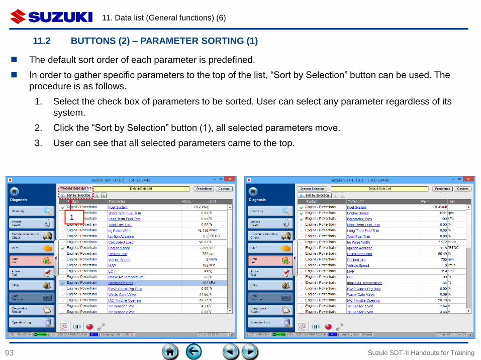
The default sort order of each parameter is predefined.
In order to gather specific parameters to the top of the list, “Sort by Selection” button can be used. The
procedure is as follows.
1. Select the check box of parameters to be sorted. User can select any parameter regardless of its
system.
2. Click the “Sort by Selection” button (1), all selected parameters move.
3. User can see that all selected parameters came to the top.
1
11. Data list (General functions) (7)
94
11.2 BUTTONS (3) – PARAMETER SORTING (2)
Suzuki SDT-II Handouts for Training
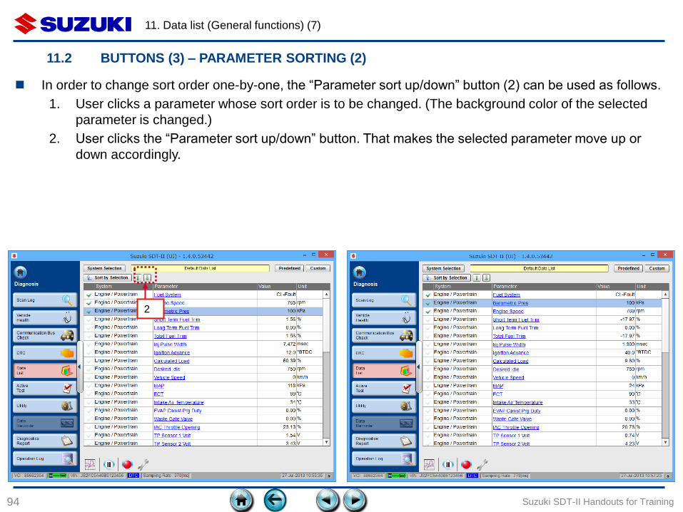
In order to change sort order one-by-one, the “Parameter sort up/down” button (2) can be used as follows.
1. User clicks a parameter whose sort order is to be changed. (The background color of the selected
parameter is changed.)
2. User clicks the “Parameter sort up/down” button. That makes the selected parameter move up or
down accordingly.
2
11. Data list (General functions) (8)
95
11.3 PREDEFINED LIST
Suzuki SDT-II Handouts for Training
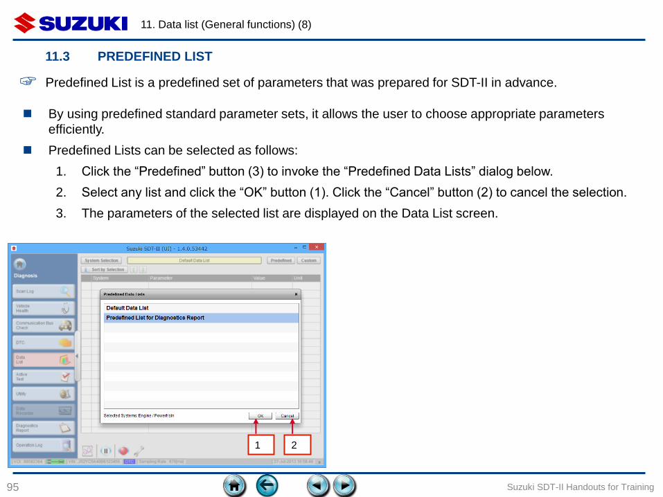
By using predefined standard parameter sets, it allows the user to choose appropriate parameters
efficiently.
Predefined Lists can be selected as follows:
1. Click the “Predefined” button (3) to invoke the “Predefined Data Lists” dialog below.
2. Select any list and click the “OK” button (1). Click the “Cancel” button (2) to cancel the selection.
3. The parameters of the selected list are displayed on the Data List screen.
☞ Predefined List is a predefined set of parameters that was prepared for SDT-II in advance.
1 2
11. Data list (General functions) (9)
96
11.4 CUSTOM LIST (1)
Suzuki SDT-II Handouts for Training
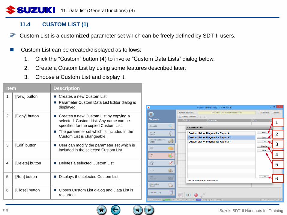
Custom List can be created/displayed as follows:
1. Click the “Custom” button (4) to invoke “Custom Data Lists” dialog below.
2. Create a Custom List by using some features described later.
3. Choose a Custom List and display it.
☞ Custom List is a customized parameter set which can be freely defined by SDT-II users.
1
Item Description
1 [New] button Creates a new Custom List
Parameter Custom Data List Editor dialog is
displayed.
2 [Copy] button Creates a new Custom List by copying a
selected Custom List. Any name can be
specified for the copied Custom List.
The parameter set which is included in the
Custom List is changeable.
3 [Edit] button User can modify the parameter set which is
included in the selected Custom List .
4 [Delete] button Deletes a selected Custom List.
5 [Run] button Displays the selected Custom List.
6 [Close] button Closes Custom List dialog and Data List is
restarted.
2
3
4
5
6
11. Data list (General functions) (10)
97
11.4 CUSTOM LIST (2)
Suzuki SDT-II Handouts for Training
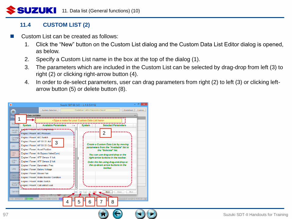
Custom List can be created as follows:
1. Click the “New” button on the Custom List dialog and the Custom Data List Editor dialog is opened,
as below.
2. Specify a Custom List name in the box at the top of the dialog (1).
3. The parameters which are included in the Custom List can be selected by drag-drop from left (3) to
right (2) or clicking right-arrow button (4).
4. In order to de-select parameters, user can drag parameters from right (2) to left (3) or clicking left-
arrow button (5) or delete button (8).
4 5
1
7
2
3
6 8
11. Data list (General functions) (11)
98
11.4 CUSTOM LIST (3)
Suzuki SDT-II Handouts for Training
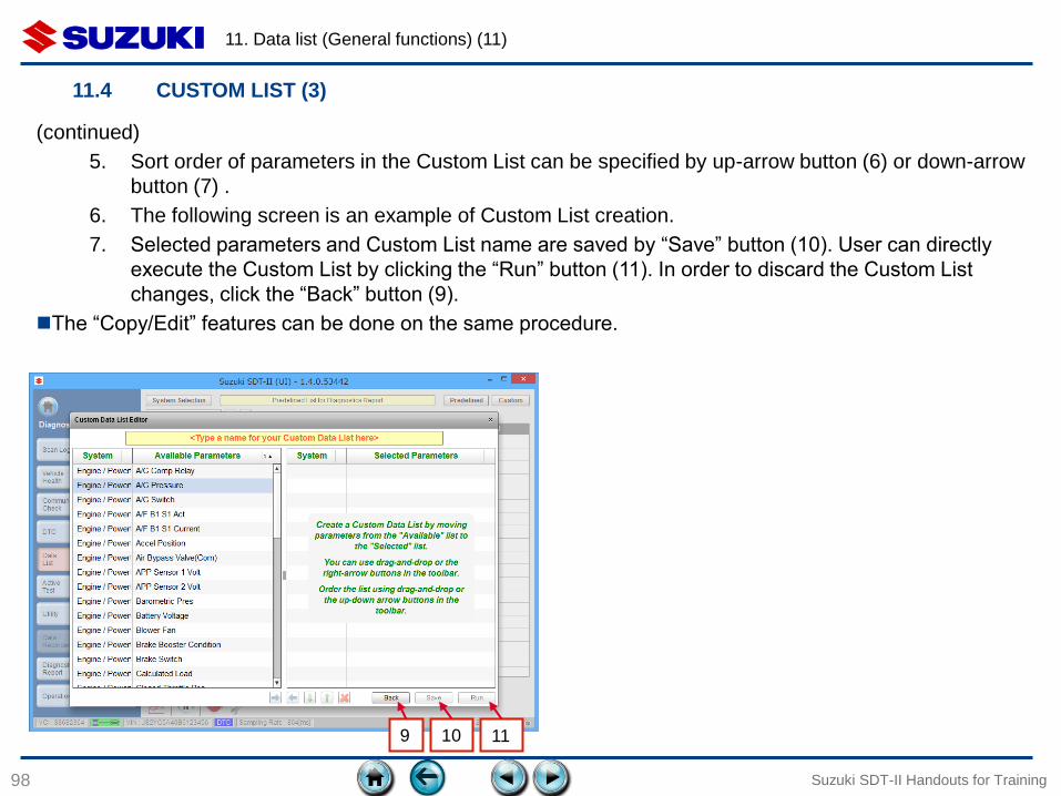
(continued)
5. Sort order of parameters in the Custom List can be specified by up-arrow button (6) or down-arrow
button (7) .
6. The following screen is an example of Custom List creation.
7. Selected parameters and Custom List name are saved by “Save” button (10). User can directly
execute the Custom List by clicking the “Run” button (11). In order to discard the Custom List
changes, click the “Back” button (9).
The “Copy/Edit” features can be done on the same procedure.
10 9 11
11. Data list (General functions) (12)
99
11.5 SNAPSHOT – OVERVIEW
Suzuki SDT-II Handouts for Training
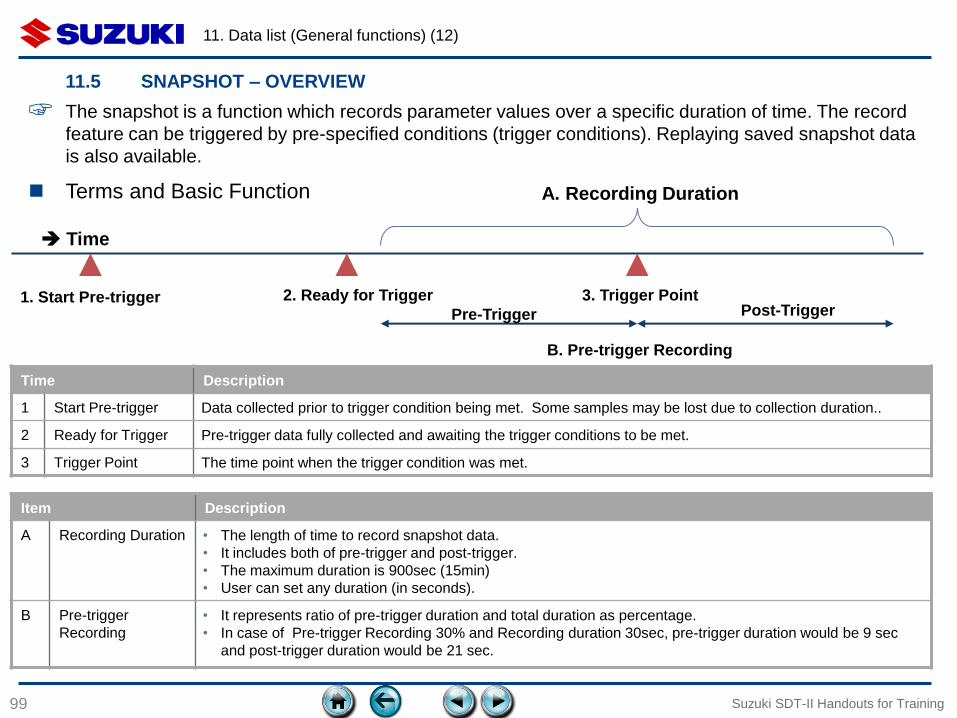
☞ The snapshot is a function which records parameter values over a specific duration of time. The record
feature can be triggered by pre-specified conditions (trigger conditions). Replaying saved snapshot data
is also available.
Terms and Basic Function
B. Pre-trigger Recording
A. Recording Duration
Time Description
1 Start Pre-trigger Data collected prior to trigger condition being met. Some samples may be lost due to collection duration..
2 Ready for Trigger Pre-trigger data fully collected and awaiting the trigger conditions to be met.
3 Trigger Point The time point when the trigger condition was met.
2. Ready for Trigger Post-Trigger
Time
1. Start Pre-trigger 3. Trigger Point
Pre-Trigger
Item Description
A Recording Duration • The length of time to record snapshot data.
• It includes both of pre-trigger and post-trigger.
• The maximum duration is 900sec (15min)
• User can set any duration (in seconds).
B Pre-trigger
Recording
• It represents ratio of pre-trigger duration and total duration as percentage.
• In case of Pre-trigger Recording 30% and Recording duration 30sec, pre-trigger duration would be 9 sec
and post-trigger duration would be 21 sec.
11. Data list (General functions) (13)
100
11.5 SNAPSHOT – BASIC OPERATION (Trigger Type : Manual) (1)
Suzuki SDT-II Handouts for Training
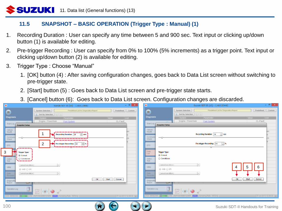
1. Recording Duration : User can specify any time between 5 and 900 sec. Text input or clicking up/down
button (1) is available for editing.
2. Pre-trigger Recording : User can specify from 0% to 100% (5% increments) as a trigger point. Text input or
clicking up/down button (2) is available for editing.
3. Trigger Type : Choose “Manual”
1. [OK] button (4) : After saving configuration changes, goes back to Data List screen without switching to
pre-trigger state.
2. [Start] button (5) : Goes back to Data List screen and pre-trigger state starts.
3. [Cancel] button (6): Goes back to Data List screen. Configuration changes are discarded.
1
2
3
4 5 6

11. Data list (General functions) (14)
101
11.5 SNAPSHOT – BASIC OPERATION (Trigger Type : Manual) (2)
Suzuki SDT-II Handouts for Training
8
4. By clicking the “Start” button ((3) above) or clicking the “Trigger” button on Data List screen, the pre-
trigger state starts (7). Notice: Snapshot recording can be started by just clicking “Trigger” button on the
Data List screen.
5. After pre-trigger duration is fulfilled, the status is changed to “Waiting trigger” (9). The progress bar
values (8) increases before “Waiting trigger” and stops until the trigger condition is met.
7 9
11. Data list (General functions) (15)
102
11.5 SNAPSHOT – BASIC OPERATION (Trigger Type : Manual) (3)
Suzuki SDT-II Handouts for Training
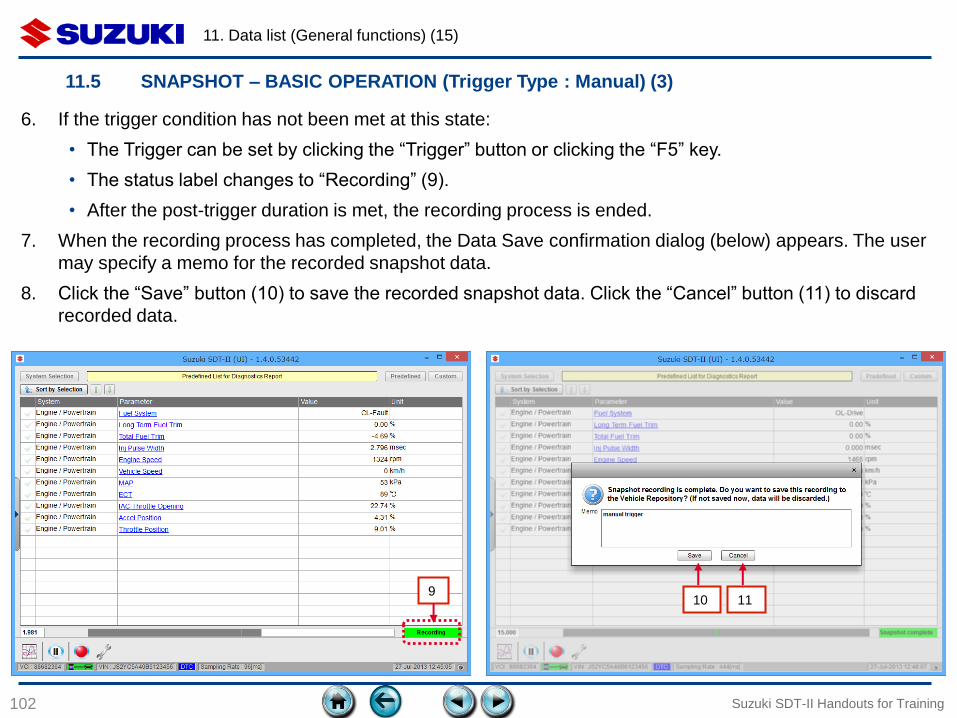
6. If the trigger condition has not been met at this state:
• The Trigger can be set by clicking the “Trigger” button or clicking the “F5” key.
• The status label changes to “Recording” (9).
• After the post-trigger duration is met, the recording process is ended.
7. When the recording process has completed, the Data Save confirmation dialog (below) appears. The user
may specify a memo for the recorded snapshot data.
8. Click the “Save” button (10) to save the recorded snapshot data. Click the “Cancel” button (11) to discard
recorded data.
9 10 11
11. Data list (General functions) (16)
103
11.5 SNAPSHOT – BASIC OPERATION (Trigger Type : Manual) (4)
Suzuki SDT-II Handouts for Training
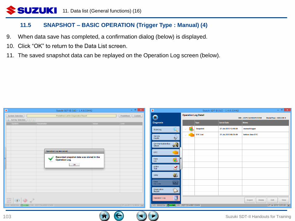
9. When data save has completed, a confirmation dialog (below) is displayed.
10. Click “OK” to return to the Data List screen.
11. The saved snapshot data can be replayed on the Operation Log screen (below).
11. Data list (General functions) (17)
104
11.5 SNAPSHOT – BASIC OPERATION (Trigger Type : Conditional) (1)
Suzuki SDT-II Handouts for Training
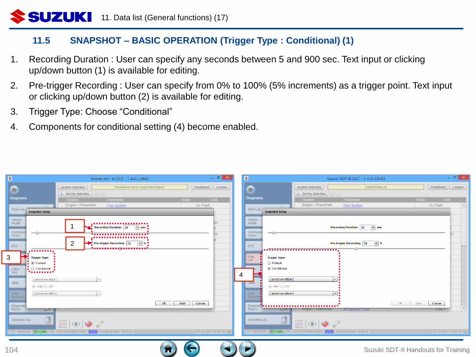
1. Recording Duration : User can specify any seconds between 5 and 900 sec. Text input or clicking
up/down button (1) is available for editing.
2. Pre-trigger Recording : User can specify from 0% to 100% (5% increments) as a trigger point. Text input
or clicking up/down button (2) is available for editing.
3. Trigger Type: Choose “Conditional”
4. Components for conditional setting (4) become enabled.
4
1
2
3
11. Data list (General functions) (18)
105
11.5 SNAPSHOT – BASIC OPERATION (Trigger Type : Conditional) (2)
Suzuki SDT-II Handouts for Training
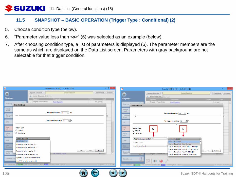
5. Choose condition type (below).
6. “Parameter value less than <x>” (5) was selected as an example (below).
7. After choosing condition type, a list of parameters is displayed (6). The parameter members are the
same as which are displayed on the Data List screen. Parameters with gray background are not
selectable for that trigger condition.
5 6
11. Data list (General functions) (19)
106
11.5 SNAPSHOT – BASIC OPERATION (Trigger Type : Conditional) (3)
Suzuki SDT-II Handouts for Training
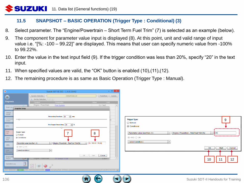
8. Select parameter. The “Engine/Powertrain – Short Term Fuel Trim” (7) is selected as an example (below).
9. The component for parameter value input is displayed (8). At this point, unit and valid range of input
value i.e. “[%: -100 – 99.22]” are displayed. This means that user can specify numeric value from -100%
to 99.22%.
10. Enter the value in the text input field (9). If the trigger condition was less than 20%, specify “20” in the text
input.
11. When specified values are valid, the “OK” button is enabled (10),(11),(12).
12. The remaining procedure is as same as Basic Operation (Trigger Type : Manual).
7 8
9
10 11 12
11. Data list (General functions) (20)
107
11.5 SNAPSHOT – BASIC OPERATION (Trigger Type : Conditional) (4)
Suzuki SDT-II Handouts for Training
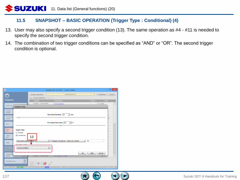
13. User may also specify a second trigger condition (13). The same operation as #4 - #11 is needed to
specify the second trigger condition.
14. The combination of two trigger conditions can be specified as “AND” or “OR”. The second trigger
condition is optional.
13
11. Data list (General functions) (21)
108
11.5 SNAPSHOT – TRIGGER SETTINGS (1)
Suzuki SDT-II Handouts for Training
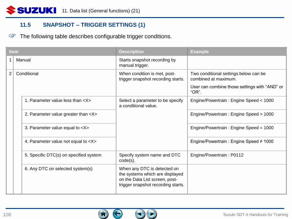
Item Description Example
1 Manual Starts snapshot recording by
manual trigger.
2 Conditional When condition is met, post-
trigger snapshot recording starts.
Two conditional settings below can be
combined at maximum.
User can combine those settings with “AND” or
“OR”.
1. Parameter value less than <X> Select a parameter to be specify
a conditional value.
Engine/Powertrain : Engine Speed < 1000
2. Parameter value greater than <X> Engine/Powertrain : Engine Speed > 1000
3. Parameter value equal to <X> Engine/Powertrain : Engine Speed = 1000
4. Parameter value not equal to <X> Engine/Powertrain : Engine Speed ≠ 1000
5. Specific DTC(s) on specified system Specify system name and DTC
code(s).
Engine/Powertrain : P0112
6. Any DTC on selected system(s) When any DTC is detected on
the systems which are displayed
on the Data List screen, post-
trigger snapshot recording starts.
☞ The following table describes configurable trigger conditions.
11. Data list (General functions) (22)
109
11.5 SNAPSHOT – TRIGGER SETTINGS (2)
Suzuki SDT-II Handouts for Training
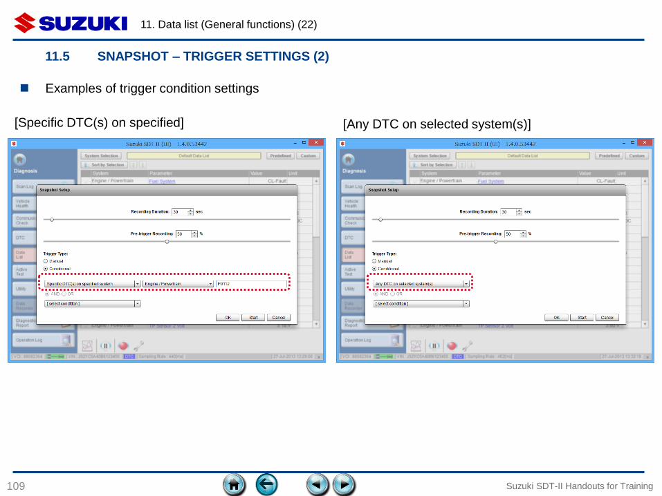
[Specific DTC(s) on specified]
Examples of trigger condition settings
[Any DTC on selected system(s)]
12. DATA LIST
(GRAPH FUNCTION)
110
12.1 Items of Graph Window
12.2 Buttons
Suzuki SDT-II Handouts for Training
12. Data List (Graph function) (1)
111
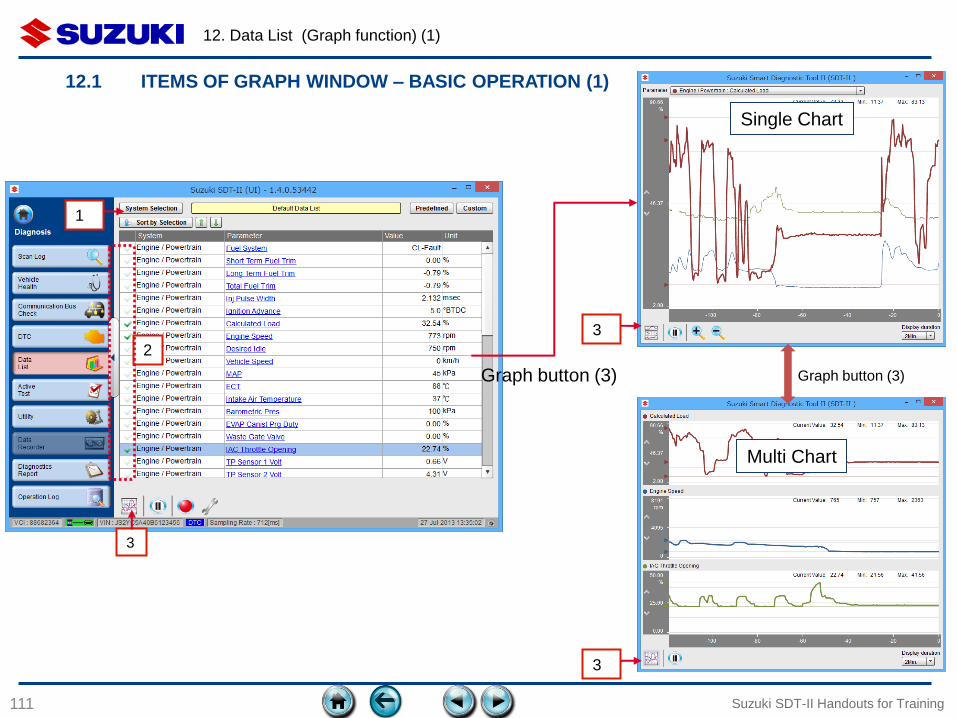
12.1 ITEMS OF GRAPH WINDOW – BASIC OPERATION (1)
Suzuki SDT-II Handouts for Training
2
Graph button (3)
Single Chart
Multi Chart
Graph button (3)
1
3
3
3
12. Data List (Graph function) (2)
112
12.1 ITEMS OF GRAPH WINDOW – BASIC OPERATION (2)
Suzuki SDT-II Handouts for Training
Process Description
1 Display Data
List
Display Data List screen and show appropriate parameters by using Predefined/Custom List feature.
Or choose system to be displayed on the graph by clicking “System Selection” button (1).
2 Select
Parameters
Select parameters (2), to be displayed on the graph.
Selecting over 20 parameters is not recommended.
3 Click [Graph]
button
Click the “Graph” button (3).
The graph window with a single chart graph is displayed. The window size is resizable.
Refer to later (ch 12.2) for items of Graph window.
4 Graph type
switch and
configuration
User can switch Graph type (Single chart Multi chart) by clicking Graph button (3) or change graph
settings based on their needs.
Refer to later (ch 12.2) for Graph settings.
12. Data List (Graph function) (3)
113
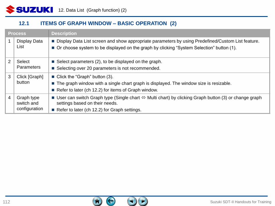
12.1 ITEMS OF GRAPH WINDOW – GRAPH TYPES (1)
Suzuki SDT-II Handouts for Training
Item Description
1 Common 3 triangle markers on vertical axis
represent Min, Max and current value of
the selected parameter. Those values are
displayed at the top-right corner on the
graph also.
The Min. Max. values are based on the
whole sampling time points, not currently
displaying time points.
Clicking the move Up/Down buttons (1)
shifts the current vertical display range
up or down.
Clicking the vertical axis area (2) invokes
Parameter Range setting dialog.
2 Multi Chart All parameters which are selected on the
Data List screen are displayed in a single
line chart (Refer to Basic Operation for
the parameter selection). A line of
selected parameter is highlighted (with
bold). The vertical axis represents the
display range of the selected parameter.
Maximum
Minimum
Current Value 1
Single Chart
2
12. Data List (Graph function) (4)
114
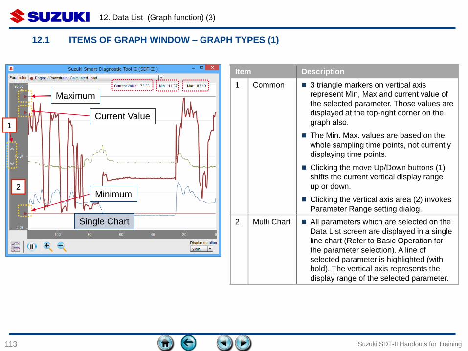
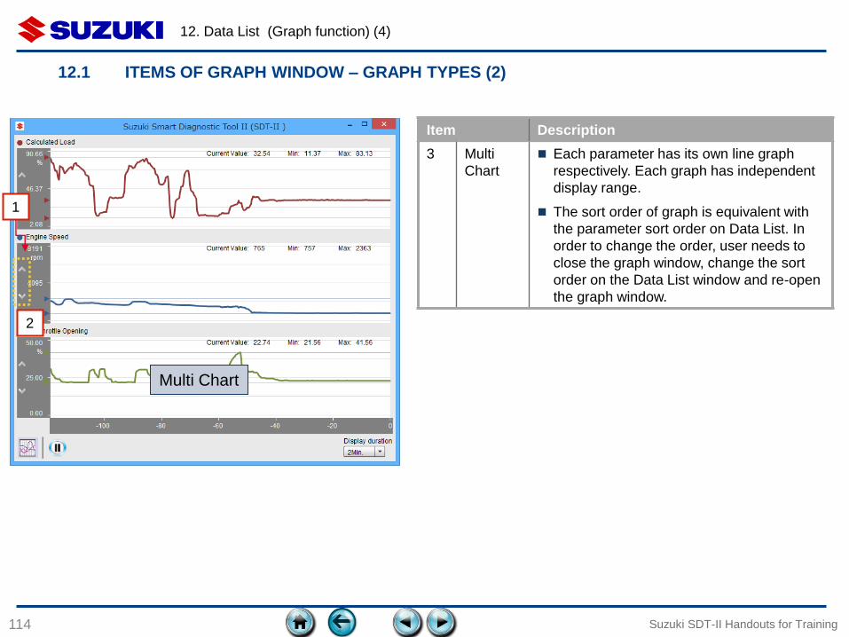
12.1 ITEMS OF GRAPH WINDOW – GRAPH TYPES (2)
Suzuki SDT-II Handouts for Training
Item Description
3 Multi
Chart
Each parameter has its own line graph
respectively. Each graph has independent
display range.
The sort order of graph is equivalent with
the parameter sort order on Data List. In
order to change the order, user needs to
close the graph window, change the sort
order on the Data List window and re-open
the graph window.
Multi Chart
1
2
12. Data List (Graph function) (5)
115
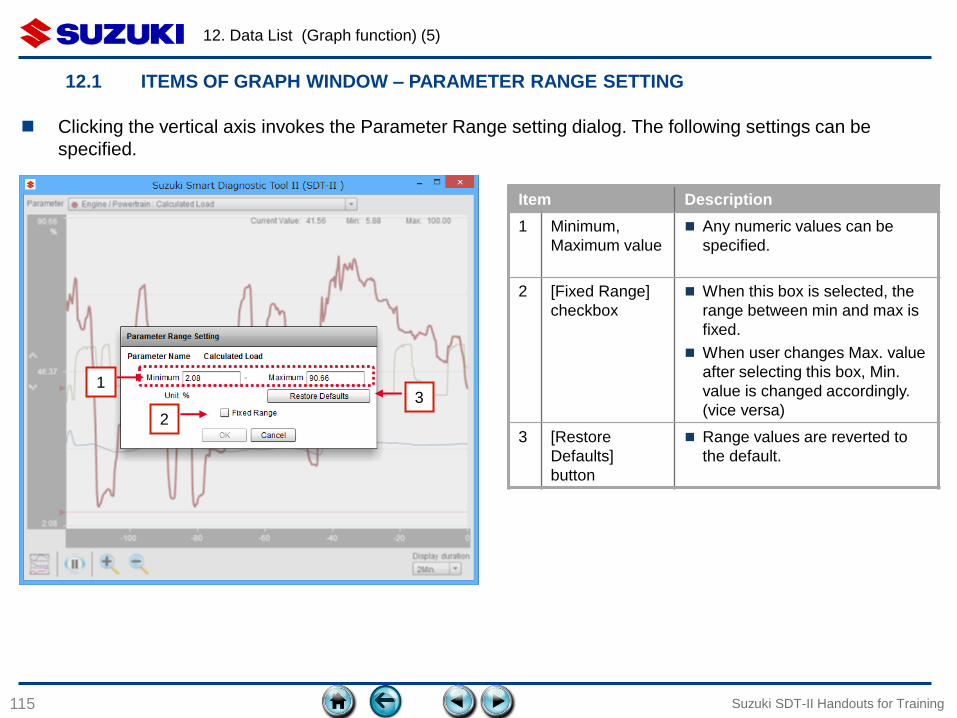
12.1 ITEMS OF GRAPH WINDOW – PARAMETER RANGE SETTING
Suzuki SDT-II Handouts for Training
Clicking the vertical axis invokes the Parameter Range setting dialog. The following settings can be
specified.
Item Description
1 Minimum,
Maximum value
Any numeric values can be
specified.
2 [Fixed Range]
checkbox
When this box is selected, the
range between min and max is
fixed.
When user changes Max. value
after selecting this box, Min.
value is changed accordingly.
(vice versa)
3 [Restore
Defaults]
button
Range values are reverted to
the default.
1
2
3
12. Data List (Graph function) (6)
116
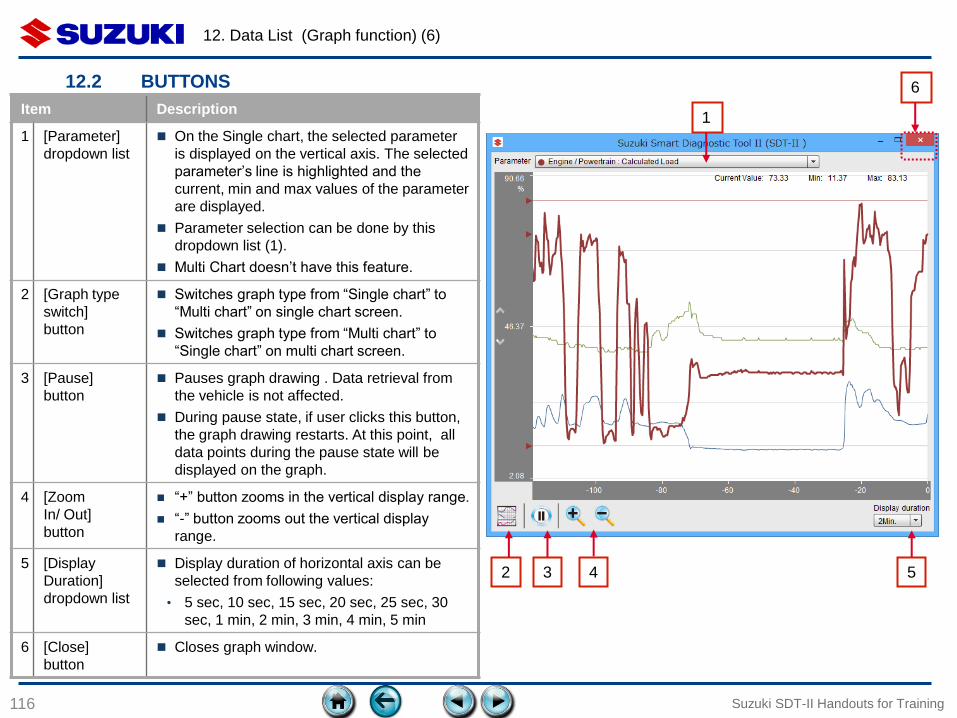
12.2 BUTTONS
Suzuki SDT-II Handouts for Training
Item Description
1 [Parameter]
dropdown list
On the Single chart, the selected parameter
is displayed on the vertical axis. The selected
parameter’s line is highlighted and the
current, min and max values of the parameter
are displayed.
Parameter selection can be done by this
dropdown list (1).
Multi Chart doesn’t have this feature.
2 [Graph type
switch]
button
Switches graph type from “Single chart” to
“Multi chart” on single chart screen.
Switches graph type from “Multi chart” to
“Single chart” on multi chart screen.
3 [Pause]
button
Pauses graph drawing . Data retrieval from
the vehicle is not affected.
During pause state, if user clicks this button,
the graph drawing restarts. At this point, all
data points during the pause state will be
displayed on the graph.
4 [Zoom
In/ Out]
button
“+” button zooms in the vertical display range.
“-” button zooms out the vertical display
range.
5 [Display
Duration]
dropdown list
Display duration of horizontal axis can be
selected from following values:
• 5 sec, 10 sec, 15 sec, 20 sec, 25 sec, 30
sec, 1 min, 2 min, 3 min, 4 min, 5 min
6 [Close]
button
Closes graph window.
1
2 3 4 5
6
13. ACTIVE TEST
117
13.1 Overview
13.2 Basic Operation
Suzuki SDT-II Handouts for Training
13. Active Test (1)
118
13.1 OVERVIEW
Suzuki SDT-II Handouts for Training
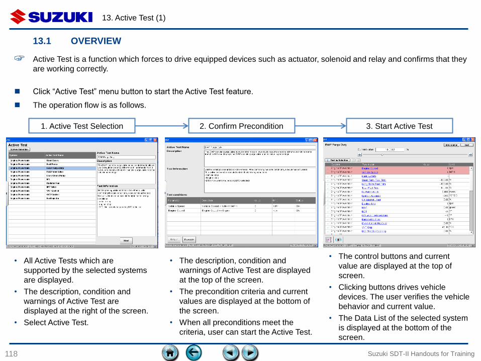
☞ Active Test is a function which forces to drive equipped devices such as actuator, solenoid and relay and confirms that they
are working correctly.
Click “Active Test” menu button to start the Active Test feature.
The operation flow is as follows.
1. Active Test Selection 2. Confirm Precondition 3. Start Active Test
• All Active Tests which are
supported by the selected systems
are displayed.
• The description, condition and
warnings of Active Test are
displayed at the right of the screen.
• Select Active Test.
• The description, condition and
warnings of Active Test are displayed
at the top of the screen.
• The precondition criteria and current
values are displayed at the bottom of
the screen.
• When all preconditions meet the
criteria, user can start the Active Test.
• The control buttons and current
value are displayed at the top of
screen.
• Clicking buttons drives vehicle
devices. The user verifies the vehicle
behavior and current value.
• The Data List of the selected system
is displayed at the bottom of the
screen.
13. Active Test (2)
119
13.2 BASIC OPERATION
Suzuki SDT-II Handouts for Training
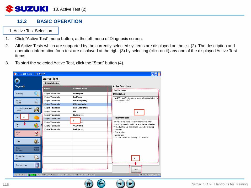
1. Click “Active Test” menu button, at the left menu of Diagnosis screen.
2. All Active Tests which are supported by the currently selected systems are displayed on the list (2). The description and
operation information for a test are displayed at the right (3) by selecting (click on it) any one of the displayed Active Test
items.
3. To start the selected Active Test, click the “Start” button (4).
1. Active Test Selection
1
2
3
4

13. Active Test (3)
120
13.2 BASIC OPERATION
Suzuki SDT-II Handouts for Training
1. The description and test information of the selected Active Test at 1.3 (above) is displayed at the top (1).
2. Precondition criteria and current values are displayed on a list (2). If the status is “NG” (with red background), the value does
not meet the criteria. When all preconditions meet the criteria, the “Execute” button (4) is enabled.
3. Click the “Execute” button (4) to start the Active Test, or the “Return” button (3) to go back to the Active Test selection screen.
1
3
2. Confirm Precondition
2
4
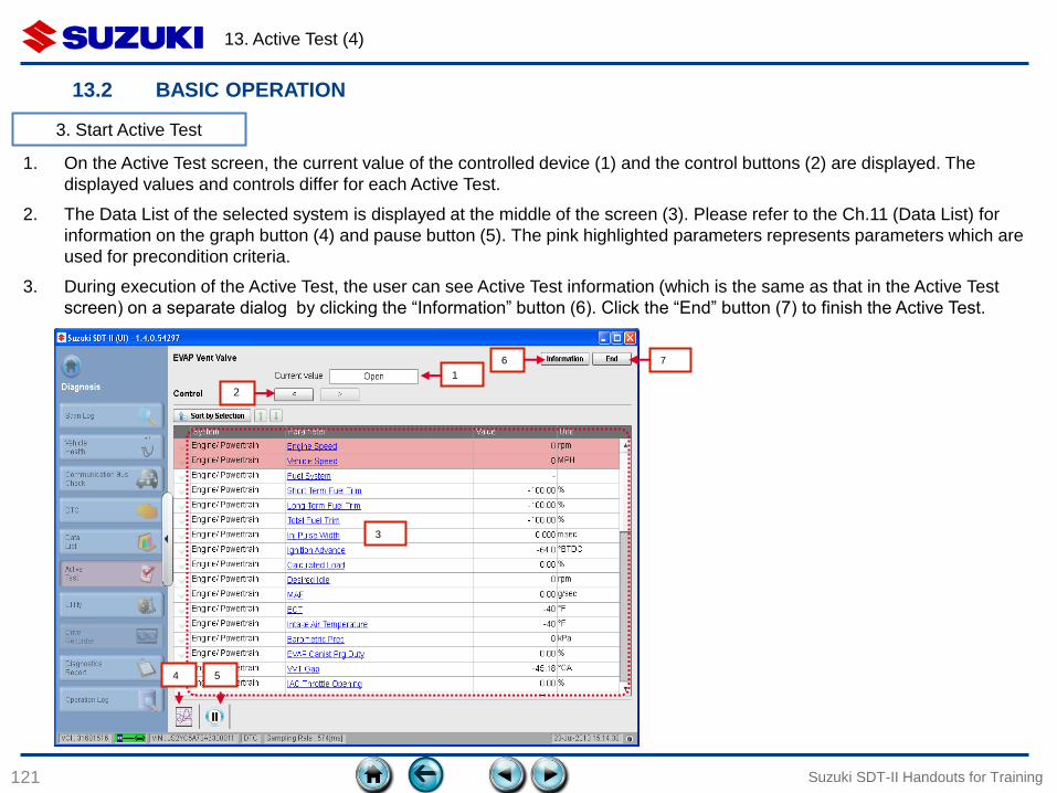
13. Active Test (4)
121
13.2 BASIC OPERATION
Suzuki SDT-II Handouts for Training
1. On the Active Test screen, the current value of the controlled device (1) and the control buttons (2) are displayed. The
displayed values and controls differ for each Active Test.
2. The Data List of the selected system is displayed at the middle of the screen (3). Please refer to the Ch.11 (Data List) for
information on the graph button (4) and pause button (5). The pink highlighted parameters represents parameters which are
used for precondition criteria.
3. During execution of the Active Test, the user can see Active Test information (which is the same as that in the Active Test
screen) on a separate dialog by clicking the “Information” button (6). Click the “End” button (7) to finish the Active Test.
3
3. Start Active Test
1
6 7
2
4 5

13. Active Test (5)
122
13.2 BASIC OPERATION
Suzuki SDT-II Handouts for Training
(continue)
4. During an Active Test, if a precondition parameter value exceeds the criteria range, the Active Test is aborted and an error
dialog is displayed.
5. Click “OK” to go back to the Active Test Selection screen.
3. Start Active Test
14. UTILITY
123
14.1 Overview
14.2 Basic Operation
Suzuki SDT-II Handouts for Training
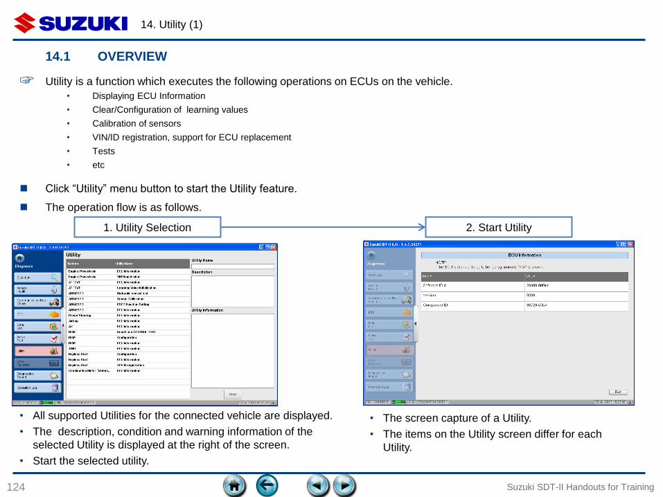
14. Utility (1)
124
14.1 OVERVIEW
Suzuki SDT-II Handouts for Training
☞ Utility is a function which executes the following operations on ECUs on the vehicle.
• Displaying ECU Information
• Clear/Configuration of learning values
• Calibration of sensors
• VIN/ID registration, support for ECU replacement
• Tests
• etc
1. Utility Selection 2. Start Utility
• All supported Utilities for the connected vehicle are displayed.
• The description, condition and warning information of the
selected Utility is displayed at the right of the screen.
• Start the selected utility.
• The screen capture of a Utility.
• The items on the Utility screen differ for each
Utility.
Click “Utility” menu button to start the Utility feature.
The operation flow is as follows.
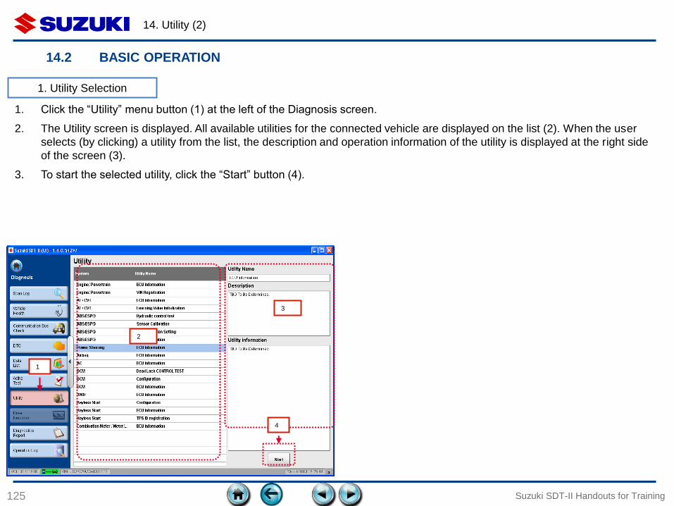
14. Utility (2)
125
14.2 BASIC OPERATION
Suzuki SDT-II Handouts for Training
1. Click the “Utility” menu button (1) at the left of the Diagnosis screen.
2. The Utility screen is displayed. All available utilities for the connected vehicle are displayed on the list (2). When the user
selects (by clicking) a utility from the list, the description and operation information of the utility is displayed at the right side
of the screen (3).
3. To start the selected utility, click the “Start” button (4).
1. Utility Selection
1
2
3
4

14. Utility (3)
126
14.2 BASIC OPERATION
Suzuki SDT-II Handouts for Training
1. The Utility which has been selected at 1.3 (above) is executed.
2. The example below is the “ECU Information” utility. Displayed items and controls are differ for each utility.
2. Start Utility
15. DIAGNOSTICS REPORT
127
15.1 Overview
15.2 Basic Operation
15.3 Items of Diagnostics Report
Suzuki SDT-II Handouts for Training
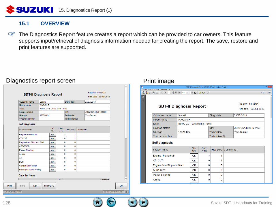
15. Diagnostics Report (1)
128 Suzuki SDT-II Handouts for Training
15.1 OVERVIEW
Diagnostics report screen Print image
☞ The Diagnostics Report feature creates a report which can be provided to car owners. This feature
supports input/retrieval of diagnosis information needed for creating the report. The save, restore and
print features are supported.
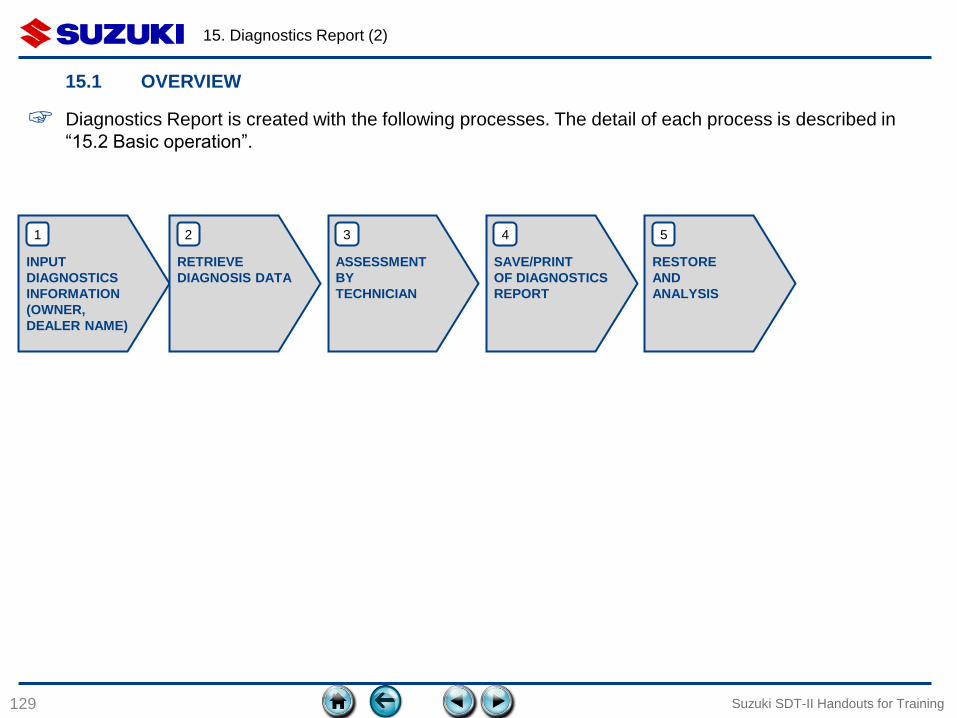
15. Diagnostics Report (2)
129 Suzuki SDT-II Handouts for Training
15.1 OVERVIEW
☞ Diagnostics Report is created with the following processes. The detail of each process is described in
“15.2 Basic operation”.
INPUT
DIAGNOSTICS
INFORMATION
(OWNER,
DEALER NAME)
RETRIEVE
DIAGNOSIS DATA
ASSESSMENT
BY
TECHNICIAN
SAVE/PRINT
OF DIAGNOSTICS
REPORT
RESTORE
AND
ANALYSIS
1 2 3 4 5
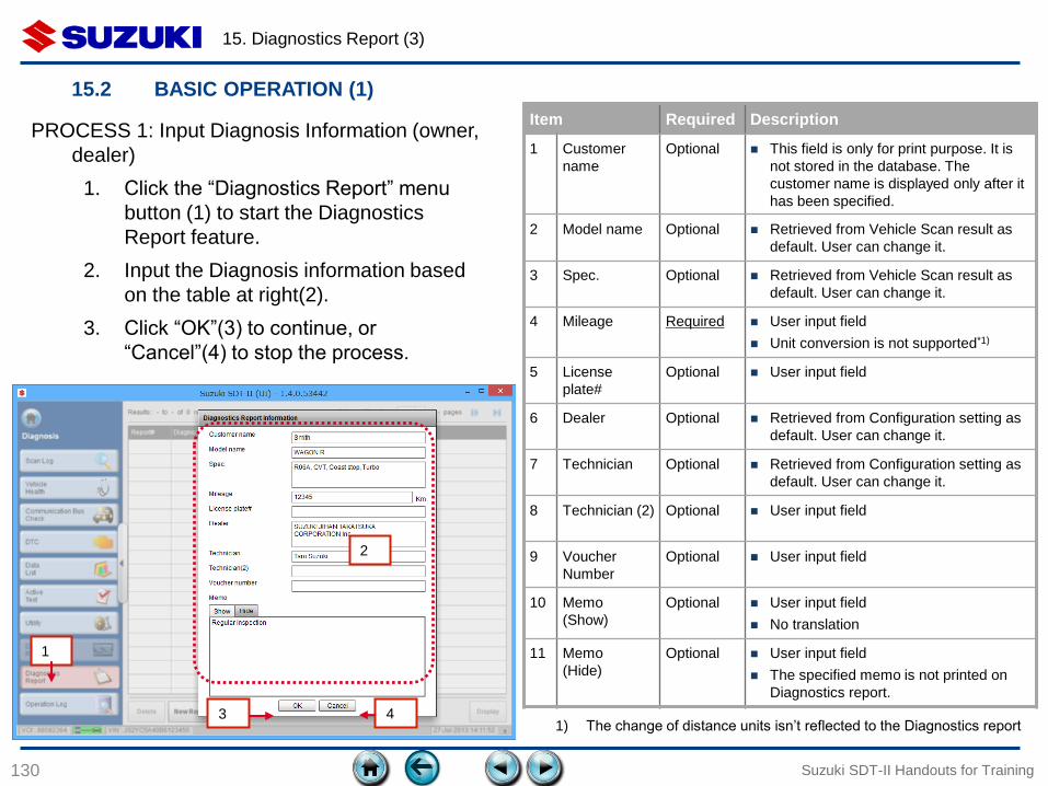
15. Diagnostics Report (3)
130 Suzuki SDT-II Handouts for Training
15.2 BASIC OPERATION (1)
PROCESS 1: Input Diagnosis Information (owner,
dealer)
1. Click the “Diagnostics Report” menu
button (1) to start the Diagnostics
Report feature.
2. Input the Diagnosis information based
on the table at right(2).
3. Click “OK”(3) to continue, or
“Cancel”(4) to stop the process.
1
2
Item Required Description
1 Customer
name
Optional This field is only for print purpose. It is
not stored in the database. The
customer name is displayed only after it
has been specified.
2 Model name Optional Retrieved from Vehicle Scan result as
default. User can change it.
3 Spec. Optional Retrieved from Vehicle Scan result as
default. User can change it.
4 Mileage Required User input field
Unit conversion is not supported*1)
5 License
plate#
Optional User input field
6 Dealer Optional Retrieved from Configuration setting as
default. User can change it.
7 Technician Optional Retrieved from Configuration setting as
default. User can change it.
8 Technician (2) Optional User input field
9 Voucher
Number
Optional User input field
10 Memo
(Show)
Optional User input field
No translation
11 Memo
(Hide)
Optional User input field
The specified memo is not printed on
Diagnostics report.
1) The change of distance units isn’t reflected to the Diagnostics report 3 4
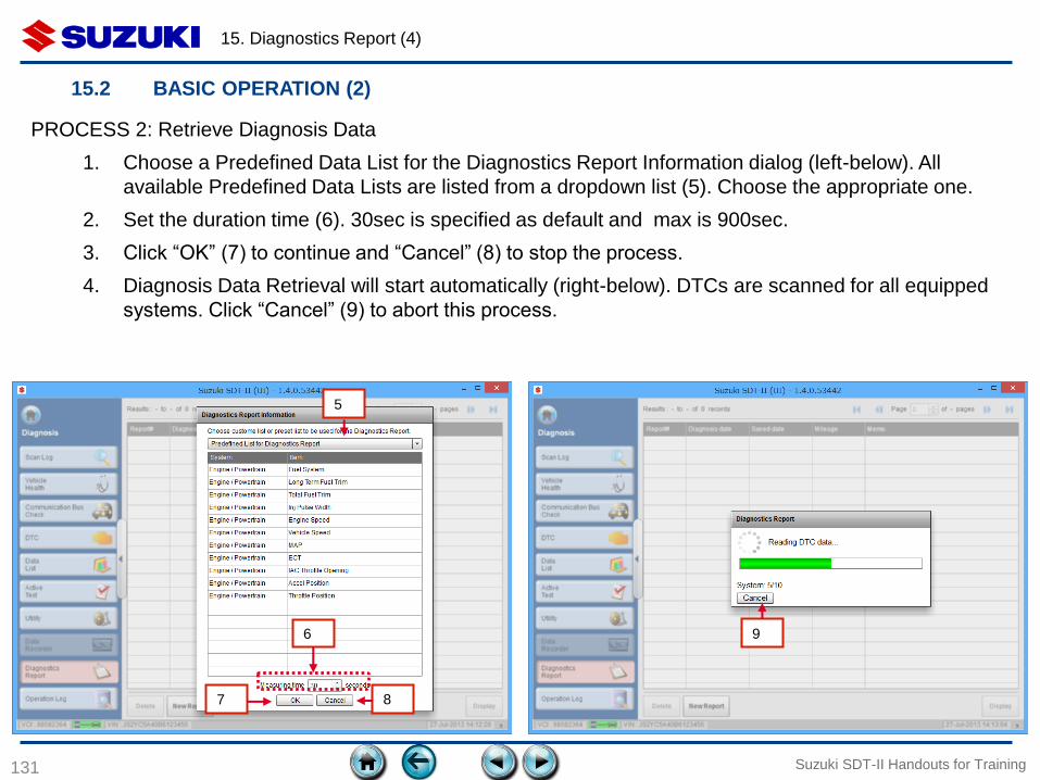
15. Diagnostics Report (4)
131 Suzuki SDT-II Handouts for Training
15.2 BASIC OPERATION (2)
PROCESS 2: Retrieve Diagnosis Data
1. Choose a Predefined Data List for the Diagnostics Report Information dialog (left-below). All
available Predefined Data Lists are listed from a dropdown list (5). Choose the appropriate one.
2. Set the duration time (6). 30sec is specified as default and max is 900sec.
3. Click “OK” (7) to continue and “Cancel” (8) to stop the process.
4. Diagnosis Data Retrieval will start automatically (right-below). DTCs are scanned for all equipped
systems. Click “Cancel” (9) to abort this process.
5
6
7 8
9
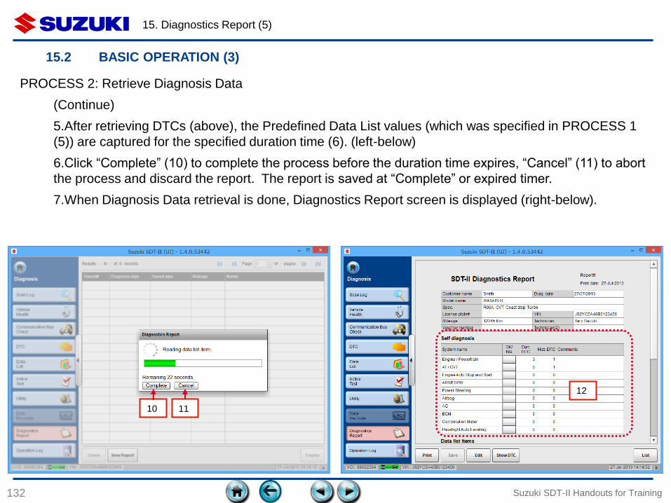
15. Diagnostics Report (5)
132 Suzuki SDT-II Handouts for Training
15.2 BASIC OPERATION (3)
PROCESS 2: Retrieve Diagnosis Data
(Continue)
5.After retrieving DTCs (above), the Predefined Data List values (which was specified in PROCESS 1
(5)) are captured for the specified duration time (6). (left-below)
6.Click “Complete” (10) to complete the process before the duration time expires, “Cancel” (11) to abort
the process and discard the report. The report is saved at “Complete” or expired timer.
7.When Diagnosis Data retrieval is done, Diagnostics Report screen is displayed (right-below).
10 11
12
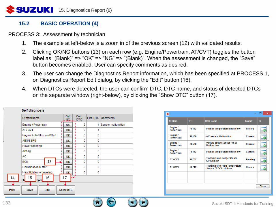
15. Diagnostics Report (6)
133 Suzuki SDT-II Handouts for Training
15.2 BASIC OPERATION (4)
PROCESS 3: Assessment by technician
1. The example at left-below is a zoom in of the previous screen (12) with validated results.
2. Clicking OK/NG buttons (13) on each row (e.g. Engine/Powertrain, AT/CVT) toggles the button
label as “(Blank)” => “OK” => “NG” => ”(Blank)”. When the assessment is changed, the “Save”
button becomes enabled. User can specify comments as desired.
3. The user can change the Diagnostics Report information, which has been specified at PROCESS 1,
on Diagnostics Report Edit dialog, by clicking the “Edit” button (16).
4. When DTCs were detected, the user can confirm DTC, DTC name, and status of detected DTCs
on the separate window (right-below), by clicking the “Show DTC” button (17).
14
13
15 16 17
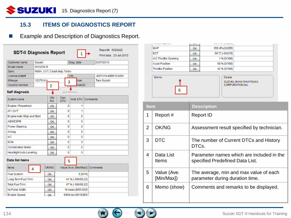
15. Diagnostics Report (7)
134 Suzuki SDT-II Handouts for Training
15.3 ITEMS OF DIAGNOSTICS REPORT
1
2 3
4
5
6
Item Description
1 Report # Report ID
2 OK/NG Assessment result specified by technician.
3 DTC The number of Current DTCs and History
DTCs.
4 Data List
Items
Parameter names which are included in the
specified Predefined Data List.
5 Value (Ave.
[Min/Max])
The average, min and max value of each
parameter during duration time.
6 Memo (show) Comments and remarks to be displayed.
Example and Description of Diagnostics Report.
16. IMMOBILIZER
135 Suzuki SDT-II Handouts for Training
16.1 PREPARATION
136
16.1.1 Difference between the SDT and the SDT-II
16.1.2 Equipment and codes for using immobilizer function
16.1.3 Obtain Activation code
16.1.4 Precautions for Security Device
Suzuki SDT-II Handouts for Training
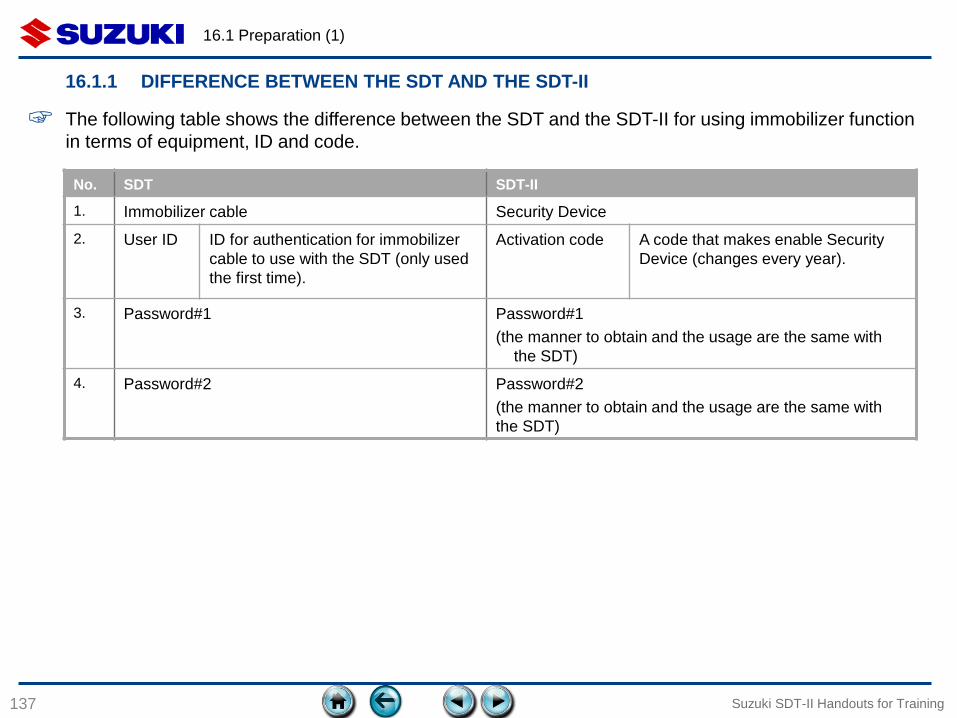
16.1 Preparation (1)
137
16.1.1 DIFFERENCE BETWEEN THE SDT AND THE SDT-II
Suzuki SDT-II Handouts for Training
☞ The following table shows the difference between the SDT and the SDT-II for using immobilizer function
in terms of equipment, ID and code.
No. SDT SDT-II
1. Immobilizer cable Security Device
2. User ID
ID for authentication for immobilizer
cable to use with the SDT (only used
the first time).
Activation code A code that makes enable Security
Device (changes every year).
3. Password#1 Password#1
(the manner to obtain and the usage are the same with
the SDT)
4. Password#2 Password#2
(the manner to obtain and the usage are the same with
the SDT)
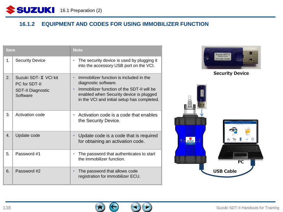
16.1 Preparation (2)
138
16.1.2 EQUIPMENT AND CODES FOR USING IMMOBILIZER FUNCTION
Suzuki SDT-II Handouts for Training
Item Note
1. Security Device • The security device is used by plugging it
into the accessory USB port on the VCI.
2. Suzuki SDT-Ⅱ VCI kit
PC for SDT-II
SDT-II Diagnostic
Software
• Immobilizer function is included in the
diagnostic software.
• Immobilizer function of the SDT-II will be
enabled when Security device is plugged
in the VCI and initial setup has completed.
3. Activation code • Activation code is a code that enables
the Security Device.
4. Update code • Update code is a code that is required
for obtaining an activation code.
5. Password #1 • The password that authenticates to start
the immobilizer function.
6. Password #2 • The password that allows code
registration for immobilizer ECU.
Security Device
USB Cable
PC
16.1 Preparation (3)
139
16.1.3 OBTAIN ACTIVATION CODE
Suzuki SDT-II Handouts for Training 139
Please ask your Suzuki distributor for instructions on how to obtain an
Activation Code.
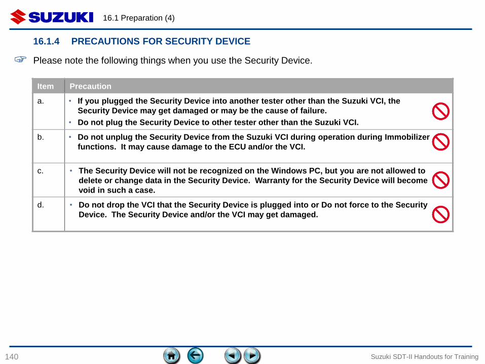
Item Precaution
a. • If you plugged the Security Device into another tester other than the Suzuki VCI, the
Security Device may get damaged or may be the cause of failure.
• Do not plug the Security Device to other tester other than the Suzuki VCI.
b. • Do not unplug the Security Device from the Suzuki VCI during operation during Immobilizer
functions. It may cause damage to the ECU and/or the VCI.
c. • The Security Device will not be recognized on the Windows PC, but you are not allowed to
delete or change data in the Security Device. Warranty for the Security Device will become
void in such a case.
d. • Do not drop the VCI that the Security Device is plugged into or Do not force to the Security
Device. The Security Device and/or the VCI may get damaged.
16.1 Preparation (4)
140
16.1.4 PRECAUTIONS FOR SECURITY DEVICE
Suzuki SDT-II Handouts for Training
☞ Please note the following things when you use the Security Device.
16.2 SETUP OF SECURITY DEVICE
141
16.2.1 Setup procedure
16.2.2 Initial configuration notes
Suzuki SDT-II Handouts for Training
16.2 Setup of Security Device (1)
142
16.2.1 INITIAL SETUP PROCEDURE (1)
Suzuki SDT-II Handouts for Training
☞ Prior to starting the initial setup, please note the following points
• Initial setup for the VCI must be completed before initiate to setup for the Security Device.
• Connection between PC and VCI must be wired. Use the USB cable. Do not use wireless
communication between PC and VCI when using the Security Device.
• Confirm the date of the PC is correct. Initial setup may not be done correctly if the date was not
correct.
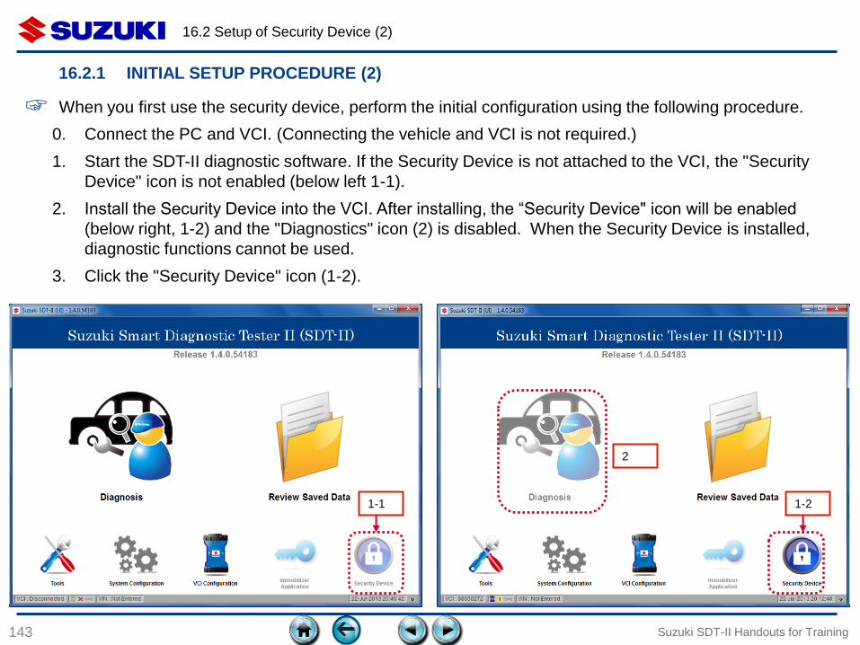
16.2 Setup of Security Device (2)
143
16.2.1 INITIAL SETUP PROCEDURE (2)
0. Connect the PC and VCI. (Connecting the vehicle and VCI is not required.)
1. Start the SDT-II diagnostic software. If the Security Device is not attached to the VCI, the "Security
Device" icon is not enabled (below left 1-1).
2. Install the Security Device into the VCI. After installing, the “Security Device" icon will be enabled
(below right, 1-2) and the "Diagnostics" icon (2) is disabled. When the Security Device is installed,
diagnostic functions cannot be used.
3. Click the "Security Device" icon (1-2).
☞ When you first use the security device, perform the initial configuration using the following procedure.
1-1 1-2
2
Suzuki SDT-II Handouts for Training
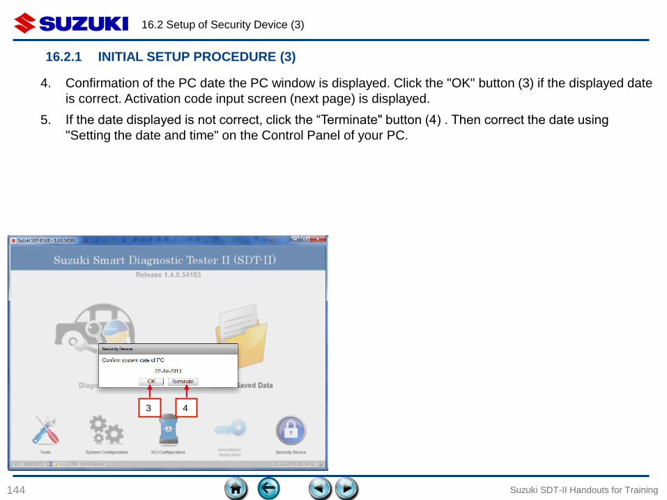
16.2 Setup of Security Device (3)
144 Suzuki SDT-II Handouts for Training
4. Confirmation of the PC date the PC window is displayed. Click the "OK" button (3) if the displayed date
is correct. Activation code input screen (next page) is displayed.
5. If the date displayed is not correct, click the “Terminate" button (4) . Then correct the date using
"Setting the date and time" on the Control Panel of your PC.
16.2.1 INITIAL SETUP PROCEDURE (3)
3 4
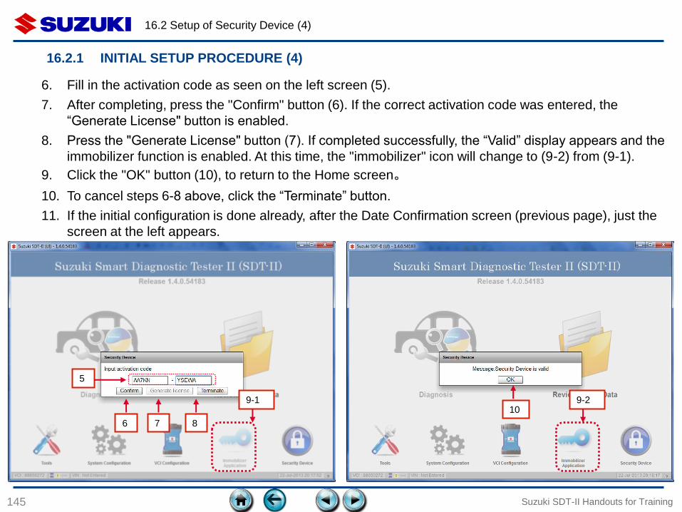
16.2 Setup of Security Device (4)
145 Suzuki SDT-II Handouts for Training
6. Fill in the activation code as seen on the left screen (5).
7. After completing, press the "Confirm" button (6). If the correct activation code was entered, the
“Generate License" button is enabled.
8. Press the "Generate License" button (7). If completed successfully, the “Valid” display appears and the
immobilizer function is enabled. At this time, the "immobilizer" icon will change to (9-2) from (9-1).
9. Click the "OK" button (10), to return to the Home screen。
10. To cancel steps 6-8 above, click the “Terminate” button.
11. If the initial configuration is done already, after the Date Confirmation screen (previous page), just the
screen at the left appears.
16.2.1 INITIAL SETUP PROCEDURE (4)
6 7 8
5
10 9-1 9-2
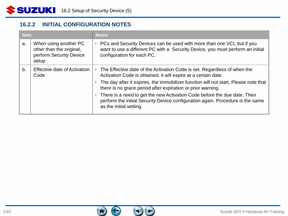
16.2 Setup of Security Device (5)
146
16.2.2 INITIAL CONFIGURATION NOTES
Suzuki SDT-II Handouts for Training
Item Notes
a. When using another PC
other than the original,
perform Security Device
setup
• PCs and Security Devices can be used with more than one VCI, but if you
want to use a different PC with a Security Device, you must perform an initial
configuration for each PC.
b. Effective date of Activation
Code
• The Effective date of the Activation Code is set. Regardless of when the
Activation Code is obtained, it will expire at a certain date.
• The day after it expires, the immobilizer function will not start. Please note that
there is no grace period after expiration or prior warning.
• There is a need to get the new Activation Code before the due date. Then
perform the initial Security Device configuration again. Procedure is the same
as the initial setting.

16.3 STARTING THE IMMOBILIZER
FUNCTION
147 Suzuki SDT-II Handouts for Training
16.3.1 Starting the Immobilizer function
16.3.2 Menu of Immobilizer function
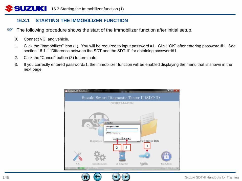
16.3 Starting the Immobilizer function (1)
148
16.3.1 STARTING THE IMMOBILIZER FUNCTION
Suzuki SDT-II Handouts for Training
☞ The following procedure shows the start of the Immobilizer function after initial setup.
0. Connect VCI and vehicle.
1. Click the “Immobilizer” icon (1). You will be required to input password #1. Click “OK” after entering password #1. See
section 16.1.1 “Difference between the SDT and the SDT-II” for obtaining password#1.
2. Click the “Cancel” button (3) to terminate.
3. If you correctly entered password#1, the immobilizer function will be enabled displaying the menu that is shown in the
next page.
1 2 3
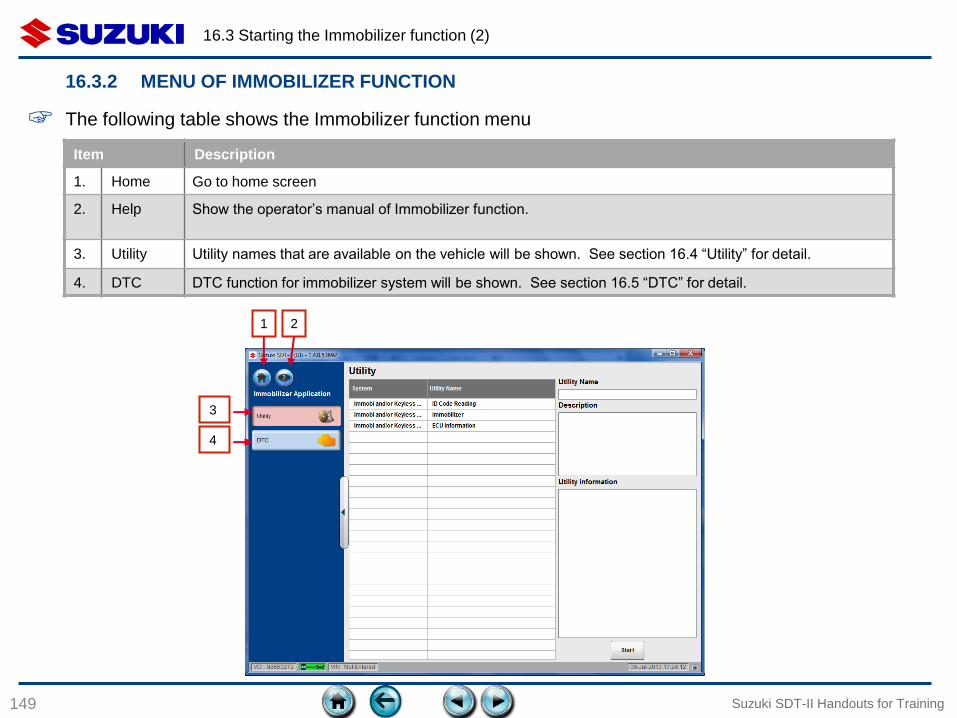
16.3 Starting the Immobilizer function (2)
149 Suzuki SDT-II Handouts for Training
16.3.2 MENU OF IMMOBILIZER FUNCTION
1
3
4
Item Description
1. Home Go to home screen
2. Help Show the operator’s manual of Immobilizer function.
3. Utility Utility names that are available on the vehicle will be shown. See section 16.4 “Utility” for detail.
4. DTC DTC function for immobilizer system will be shown. See section 16.5 “DTC” for detail.
☞ The following table shows the Immobilizer function menu
2
16.4 UTILITY
150
16.4.1 ID code read
16.4.2 Immobilizer registration
Suzuki SDT-II Handouts for Training
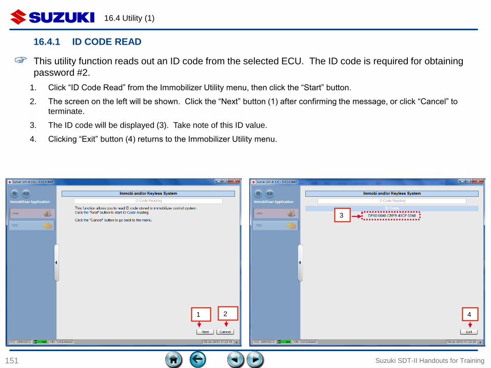
16.4 Utility (1)
151
16.4.1 ID CODE READ
Suzuki SDT-II Handouts for Training
3
4 1
☞ This utility function reads out an ID code from the selected ECU. The ID code is required for obtaining
password #2.
2
1. Click “ID Code Read” from the Immobilizer Utility menu, then click the “Start” button.
2. The screen on the left will be shown. Click the “Next” button (1) after confirming the message, or click “Cancel” to
terminate.
3. The ID code will be displayed (3). Take note of this ID value.
4. Clicking “Exit” button (4) returns to the Immobilizer Utility menu.
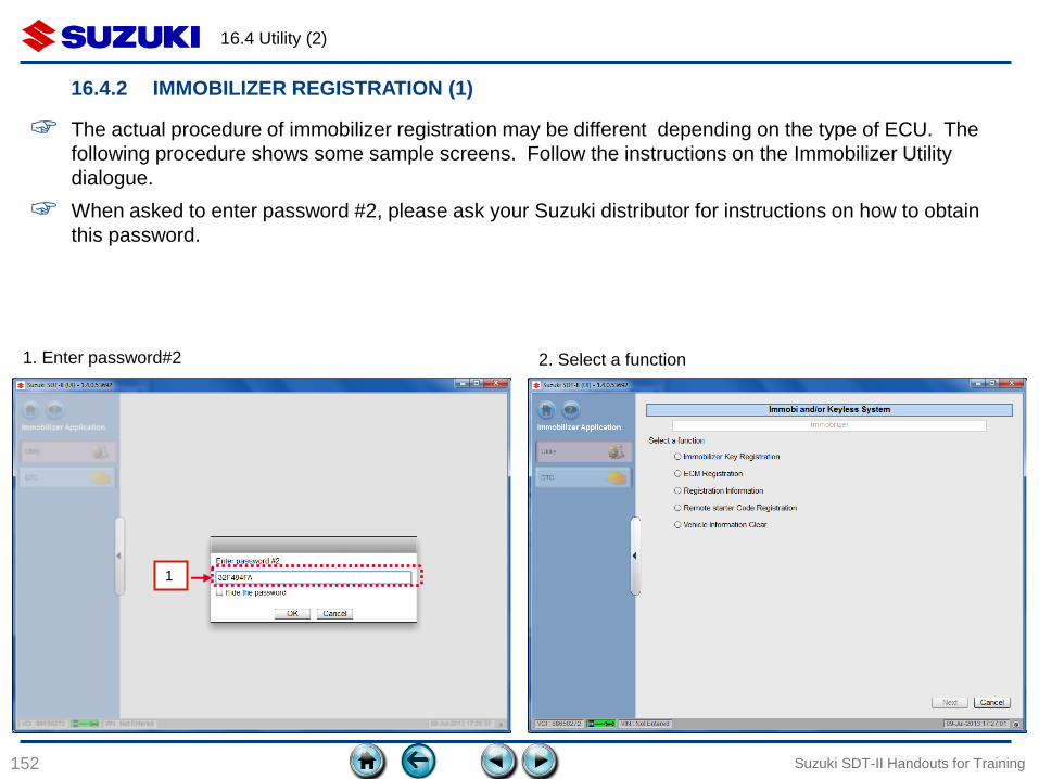
16.4 Utility (2)
152
16.4.2 IMMOBILIZER REGISTRATION (1)
Suzuki SDT-II Handouts for Training
☞ The actual procedure of immobilizer registration may be different depending on the type of ECU. The
following procedure shows some sample screens. Follow the instructions on the Immobilizer Utility
dialogue.
☞ When asked to enter password #2, please ask your Suzuki distributor for instructions on how to obtain
this password.
1
1. Enter password#2 2. Select a function
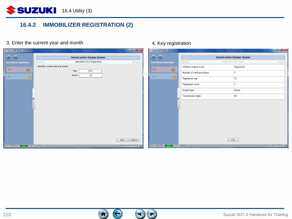
16.4 Utility (3)
153 Suzuki SDT-II Handouts for Training
3. Enter the current year and month 4. Key registration
16.4.2 IMMOBILIZER REGISTRATION (2)
16.5 DTC
154
16.5.1 DTC display
Suzuki SDT-II Handouts for Training
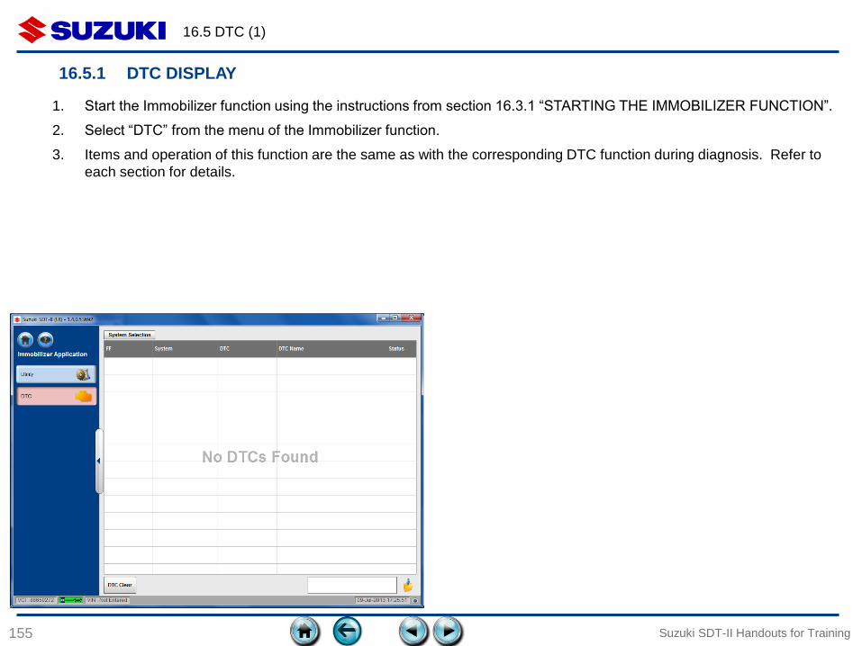
16.5 DTC (1)
155
16.5.1 DTC DISPLAY
Suzuki SDT-II Handouts for Training
1. Start the Immobilizer function using the instructions from section 16.3.1 “STARTING THE IMMOBILIZER FUNCTION”.
2. Select “DTC” from the menu of the Immobilizer function.
3. Items and operation of this function are the same as with the corresponding DTC function during diagnosis. Refer to
each section for details.
156
Diagnostic Tester
Suzuki SDT-II
Handouts for Training
version 1.0
issued on July 17th 2013
End of document.
Suzuki SDT-II Handouts for Training