diagnostic trouble code diagnosis · system check. is the system check complete? – go to step 2...
TRANSCRIPT

ENGINE CONTROLS 1F – 55
DAEWOO M-150 BL2
DIAGNOSTIC TROUBLE CODE DIAGNOSISCLEARING TROUBLE CODESNotice: To prevent Engine Control Module (ECM) dam-age, the key must be OFF when disconnecting or recon-necting the power to the ECM (for example batterycable, ECM pigtail connector, ECM fuse, jumper cables,etc.).When the ECM sets a Diagnostic Trouble Code(DTC), the Malfunction Indicator Lamp (MIL) lamp willbe turned on only for type A, B and E but a DTC will bestored in the ECM’s memory for all types of DTC. If the
problem is intermittent, the MIL will go out after 10 sec-onds if the fault is no longer present. The DTC will stayin the ECM’s memory until cleared by scan tool. Remov-ing battery voltage for 10 seconds will clear some storedDTCs.DTCs should be cleared after repairs have been com-pleted. Some diagnostic tables will tell you to clear thecodes before using the chart. This allows the ECM to setthe DTC while going through the chart, which will help tofind the cause of the problem more quickly.
DIAGNOSTIC TROUBLE CODES
DTC Function Error Type Illuminate MIL
P0107 Manifold Absolute Pressure Sensor Low Voltage A YES
P0108 Manifold Absolute Pressure Sensor High voltage A YES
P0112 Intake Air Temperature Sensor Low Voltage E YES
P0113 Intake Air Temperature Sensor High voltage E YES
P0117 Engine Coolant Temperature Sensor Low Voltage A YES
P0118 Engine Coolant Temperature Sensor High voltage A YES
P0122 Throttle Position Sensor Low Voltage A YES
P0123 Throttle Position Sensor Hig voltage A YES
P0131 Oxygen Sensor Low Voltage A YES
P0132 Oxygen Sensor High Voltage A YES
P0133 Oxygen Sensor No Activity E YES
P0137 Heated Oxygen Sensor Low Voltage E YES
P0138 Heated Oxygen Sensor high voltage E YES
P0140 Heated Oxygen Sensor No Activity E YES
P0141 Heated Oxygen Sensor Heater Malfuction E YES
P0171 Fuel Trim System Too Lean E YES
P0172 Fuel Trim System Too Rich E YES
P1230 Fuel Pump Relay Low Voltage A YES
P1231 Fuel Pump Relay High Voltage A YES
P0261 Injector 1 Low Voltage A YES
P0262 Injector 1 high voltage A YES
P0264 Injector 2 Low Voltage A YES
P0265 Injector 2 high voltage A YES
P0267 Injector 3 Low Voltage A YES
P0268 Injector 3 high voltage A YES
P0300 Multifle Cylinder Misfire A/E BLINKING/ON
P1320 Crankshatft Segment Period Segment Adaptation At Limit E YES
P1321 Crankshatft Segment Period Tooth Error E YES
P0327 Knock Sensor Circuit Fault E YES
P0335 Magnetic Crankshaft Position Sensor Electrical Error E YES

1F – 56 ENGINE CONTROLS
DAEWOO M-150 BL2
Diagnostic Trouble Codes (Cont’d)
DTC Function Error Type Illuminate MIL
P0336 58X Crankshaft Position Sensor Extra/missing Pulse E YES
P0337 58X Crankshaft Sensor No Signal E YES
P0341 Camshaft Position Sensor Rationality E YES
P0342 Camshaft Position Sensor No Signal E YES
P0351 Ignition Signal Coil A Fault A YES
P0352 Ignition Signal Coil B Fault A YES
P0353 Ignition Signal Coil C Fault A YES
P1382 Rough Road Data Invalid (Non ABS) Cnl NO
P1382 Rrough Road Data Invalid (ABS) Cnl NO
P1385 Rough Road Sensor Circuit Fault (Non ABS) Cnl NO
P1385 Rough Road Sensor Circuit Fault (ABS) Cnl NO
P0400 Exhaust Gas Recirculation Out of Limit E YES
P1402 Exhaust Gas Recirculation Blocked E YES
P1403 Exhaust Gas Recirculation Valve Failure E YES
P0404 Electric Exhaust Gas Recirculation (EEGR) Opend E YES
P1404 Electric Exhaust Gas Recirculation (EEGR) Closed E YES
P0405 EEGR Pintle Position Sensor Low Voltage E YES
P0406 EEGR Pintle Position Sensor High voltage E YES
P0420 Catalyst Low Efficiency E YES
P0444 EVAP Purge Control Circuit No Signal E YES
P0445 EVAP Purge Control Circuit Fault E YES
P0462 Fuel Level Sensor Low Voltage Cnl NO
P0463 Fuel Level Sensor High voltage Cnl NO
P0480 Low Speed Cooling Fan Relay Circuit Fault (Without A/C) Cnl NO
P0480 Low Speed Cooling Fan Relay Circuit Fault (With A/C) Cnl NO
P0481 High Speed Cooling Fan Relay High Voltage (Without A/C) Cnl NO
P0481 High Speed Cooling Fan Relay High Voltage (With A/C) Cnl NO
P0501 Vehicle Speed No Signal (M/T Only) A YES
P0505 Idle Air Control Valve (IACV) Error E YES
P1535 Evaporator Temperature Sensor High Voltage Cnl NO
P1536 Evaporator Temperature Sensor Low Voltage Cnl NO
P1537 A/C Compressor Relay High Voltage Cnl NO
P1538 A/C Compressor Relay Low Voltage Cnl NO
P0562 System Voltage (Engine Side) Too Low Cnl NO
P0563 System Voltage (Engine Side) Too High Cnl NO
P0601 Engine Control Module Checksum Error E YES
P0604 Engine Control Module RAM Error E YES
P0605 Engine Control Module NMVY Write Error E YES
P1610 Main Relay High Voltage A YES
P1611 Main Relay Low Voltage A YES
P1628 Immobilizer No Successful Communication Cnl NO
P1629 Immobilizer Wrong Computation Cnl NO
P0656 Fuel Level Gauge High Circuit Fault Cnl NO

ENGINE CONTROLS 1F – 57
DAEWOO M-150 BL2
Diagnostic Trouble Codes (Cont’d)
DTC Function Error Type Illuminate MIL
P1660 Malfunction Indicator Lamp(MIL) High Voltage E YES
P1661 Malfunction Indicator Lamp(MIL) Low Voltage E YES
1F – 58 ENGINE CONTROLS
DAEWOO M-150 BL2
MAA1F060
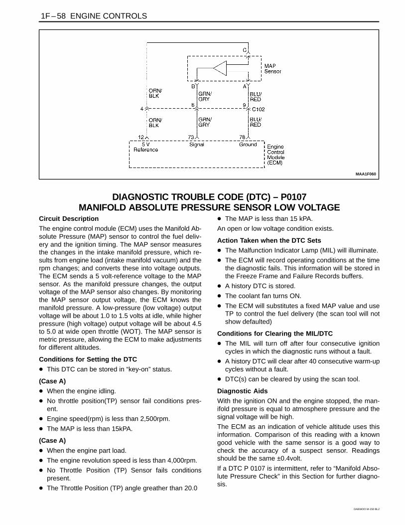
DIAGNOSTIC TROUBLE CODE (DTC) – P0107MANIFOLD ABSOLUTE PRESSURE SENSOR LOW VOLTAGE
Circuit Description
The engine control module (ECM) uses the Manifold Ab-solute Pressure (MAP) sensor to control the fuel deliv-ery and the ignition timing. The MAP sensor measuresthe changes in the intake manifold pressure, which re-sults from engine load (intake manifold vacuum) and therpm changes; and converts these into voltage outputs.The ECM sends a 5 volt-reference voltage to the MAPsensor. As the manifold pressure changes, the outputvoltage of the MAP sensor also changes. By monitoringthe MAP sensor output voltage, the ECM knows themanifold pressure. A low-pressure (low voltage) outputvoltage will be about 1.0 to 1.5 volts at idle, while higherpressure (high voltage) output voltage will be about 4.5to 5.0 at wide open throttle (WOT). The MAP sensor ismetric pressure, allowing the ECM to make adjustmentsfor different altitudes.
Conditions for Setting the DTC
This DTC can be stored in “key-on” status.
(Case A)
When the engine idling.
No throttle position(TP) sensor fail conditions pres-ent.
Engine speed(rpm) is less than 2,500rpm.
The MAP is less than 15kPA.
(Case A)
When the engine part load.
The engine revolution speed is less than 4,000rpm.
No Throttle Position (TP) Sensor fails conditionspresent.
The Throttle Position (TP) angle greather than 20.0
The MAP is less than 15 kPA.
An open or low voltage condition exists.
Action Taken when the DTC Sets
The Malfunction Indicator Lamp (MIL) will illuminate.
The ECM will record operating conditions at the timethe diagnostic fails. This information will be stored inthe Freeze Frame and Failure Records buffers.
A history DTC is stored.
The coolant fan turns ON.
The ECM will substitutes a fixed MAP value and useTP to control the fuel delivery (the scan tool will notshow defaulted)
Conditions for Clearing the MIL/DTC
The MIL will turn off after four consecutive ignitioncycles in which the diagnostic runs without a fault.
A history DTC will clear after 40 consecutive warm-upcycles without a fault.
DTC(s) can be cleared by using the scan tool.
Diagnostic Aids
With the ignition ON and the engine stopped, the man-ifold pressure is equal to atmosphere pressure and thesignal voltage will be high.
The ECM as an indication of vehicle altitude uses thisinformation. Comparison of this reading with a knowngood vehicle with the same sensor is a good way tocheck the accuracy of a suspect sensor. Readingsshould be the same ±0.4volt.
If a DTC P 0107 is intermittent, refer to “Manifold Abso-lute Pressure Check” in this Section for further diagno-sis.
ENGINE CONTROLS 1F– 59
DAEWOO M-150 BL2
If the connections are OK monitor the manifold absolutepressure (MAP) sensor signal voltage while moving re-lated connectors and the wiring harness. If the failure is
induced, the display on the scan tool will change. Thismay help to isolate the location of an intermittent mal-function.
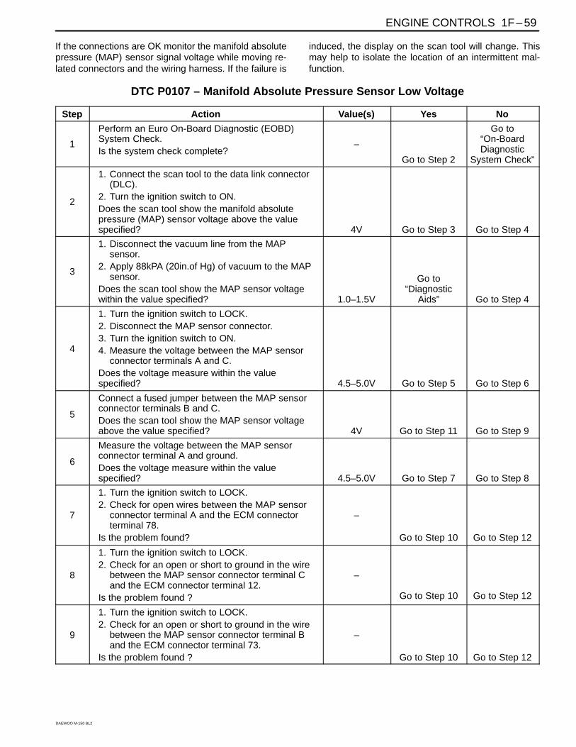
DTC P0107 – Manifold Absolute Pressure Sensor Low Voltage
Step Action Value(s) Yes No
1
Perform an Euro On-Board Diagnostic (EOBD)System Check.Is the system check complete?
–
Go to Step 2
Go to“On-BoardDiagnostic
System Check”
2
1. Connect the scan tool to the data link connector(DLC).
2. Turn the ignition switch to ON.Does the scan tool show the manifold absolutepressure (MAP) sensor voltage above the valuespecified? 4V Go to Step 3 Go to Step 4
3
1. Disconnect the vacuum line from the MAPsensor.
2. Apply 88kPA (20in.of Hg) of vacuum to the MAPsensor.
Does the scan tool show the MAP sensor voltagewithin the value specified? 1.0–1.5V
Go to“Diagnostic
Aids” Go to Step 4
4
1. Turn the ignition switch to LOCK.2. Disconnect the MAP sensor connector.3. Turn the ignition switch to ON.4. Measure the voltage between the MAP sensor
connector terminals A and C.Does the voltage measure within the valuespecified? 4.5–5.0V Go to Step 5 Go to Step 6
5
Connect a fused jumper between the MAP sensorconnector terminals B and C.Does the scan tool show the MAP sensor voltageabove the value specified? 4V Go to Step 11 Go to Step 9
6
Measure the voltage between the MAP sensorconnector terminal A and ground.Does the voltage measure within the valuespecified? 4.5–5.0V Go to Step 7 Go to Step 8
7
1. Turn the ignition switch to LOCK.2. Check for open wires between the MAP sensor
connector terminal A and the ECM connectorterminal 78.
Is the problem found?
–
Go to Step 10 Go to Step 12
8
1. Turn the ignition switch to LOCK.2. Check for an open or short to ground in the wire
between the MAP sensor connector terminal Cand the ECM connector terminal 12.
Is the problem found ?
–
Go to Step 10 Go to Step 12
9
1. Turn the ignition switch to LOCK.2. Check for an open or short to ground in the wire
between the MAP sensor connector terminal Band the ECM connector terminal 73.
Is the problem found ?
–
Go to Step 10 Go to Step 12

1F – 60 ENGINE CONTROLS
DAEWOO M-150 BL2
DTC P0107 – Manifold Absolute Pressure Sensor Low Voltage (Cont’d)
Step Action Value(s) Yes No
10
1. Repair the wire or the connector terminal asneeded.
2. Clear any DTCs from the ECM.3. Perform the diagnostic system check.Is the repair complete?
–
System OK
–
11
1. Replace the manifold absolute pressure sensor.2. Clear any DTCs from the ECM.3. Perform the diagnostic system check.Is the replacement complete?
–
System OK
–
12Replace the ECM.Is the replacement complete?
–Go to Step 13 Go to Step 2
13Check if any additional DTCs are set.Are any DTCs displaced that have not beendiagnosed?
–Go to
applicable DTCtable System OK

ENGINE CONTROLS 1F – 61
DAEWOO M-150 BL2
BLANK

1F – 62 ENGINE CONTROLS
DAEWOO M-150 BL2
MAA1F060
DIAGNOSTIC TROUBLE CODE (DTC) – P0108 MANIFOLD ABSOLUTEPRESSURE SENSOR HIGH VOLTAGE
Circuit Description
The engine control module (ECM) uses the Manifold Ab-solute Pressure (MAP) sensor to control the fuel deliv-ery and the ignition timing. The MAP sensor measuresthe changes in the intake manifold pressure, which re-sults from engine load (intake manifold vacuum) and therpm changes; and converts these into voltage outputs.The ECM sends a 5 volt-reference voltage to the MAPsensor. As the manifold pressure changes, the outputvoltage of the MAP sensor also changes. By monitoringthe MAP sensor output voltage, the ECM knows themanifold pressure. A low-pressure (low voltage) outputvoltage will be about 1.0 to 1.5 volts at idle, while higherpressure (high voltage) output voltage will be about 4.5to 4.8 at wide open throttle (WOT). The MAP sensor ismetric pressure, allowing the ECM to make adjustmentsfor different altitudes.
Conditions for Setting the DTC
This DTC can be stored in “key-on” status.
Engine speed is greater than 2,000rpm.
No throttle position sensor (TPS) fail conditions pres-ent.
The MAP is greater than 600m bar.
A high voltage condition exists.
Action Taken when the DTC Sets
The Malfunction Indicator Lamp (MIL) will illuminate.
The ECM will record operating conditions at the timethe diagnostic fails. This information will be stored inthe Freeze Frame and Failure Records buffers.
A history DTC is stored.
The ECM will substitutes a fixed MAP value and useTP to control the fuel delivery (the scan tool will notshow defaulted)
Conditions for Clearing the MIL/DTC
The MIL will turn off after four consecutive ignitioncycles in which the diagnostic runs without a fault.
A history DTC will clear after 40 consecutive warm-upcycles without a fault.
DTC(s) can be cleared by using the scan tool.
Diagnostic Aids
With the ignition ON and the engine stopped, the man-ifold pressure is equal to atmosphere pressure and thesignal voltage will be high.
The ECM as an indication of vehicle altitude uses thisinformation. Comparison of this reading with a knowngood vehicle with the same sensor is a good way tocheck the accuracy of a suspect sensor. Readingsshould be the same ±0.4volt.
If a DTC P 0108 is intermittent, refer to “manifold abso-lute pressure check” in this Section for further diagnosis.
If the connections are OK monitor the manifold absolutepressure(MAP) sensor signal voltage while moving re-lated connectors and the wiring harness. If the failure isinduced, the display on the scan tool will change. Thismay help to isolate the location of an intermittent mal-function.

ENGINE CONTROLS 1F – 63
DAEWOO M-150 BL2
DTC P0108 – Manifold Absolute Pressure Sensor High Voltage
Step Action Value(s) Yes No
1
Perform an Euro On-Board Diagnostic (EOBD)System Check.Is the system check complete?
–
Go to Step 2
Go to“On-BoardDiagnostic
System Check”
2
1. Connect the scan tool to the data link connector(DLC).
2. Turn the ignition switch to ON.Does the scan tool show the manifold absolutepressure (MAP) sensor voltage above the valuespecified? 4V Go to Step 3 Go to Step 4
3
1. Disconnect the vacuum line from the MAPsensor.
2. Apply 66kPA (20in.of Hg) of vacuum to the MAPsensor.
Does the scan tool show the MAP sensor voltagewithin the value specified? 1.0–1.5V
Go to“Diagnostic
Aids” Go to Step 4
4
1. Turn the ignition switch to LOCK.2. Disconnect the MAP sensor connector.3. Turn the ignition switch to ON.4. Measure the voltage between the MAP sensor
connector terminals A and C.Does the voltage measure within the valuespecified? 4.5–5.0V Go to Step 5 Go to Step 6
5
Connect a fused jumper between the MAP sensorconnector terminals B and C.Does the scan tool show the MAP sensor voltageabove the value specified? 4V Go to Step 11 Go to Step 9
6
Measure the voltage between the MAP sensorconnector terminal A and ground.Does the voltage measure within the valuespecified? 4.5–5.0V Go to Step 7 Go to Step 8
7
1. Turn the ignition switch to LOCK.2. Check for open wires between the MAP sensor
connector terminal A and the ECM connectorterminal 78.
Is the problem found?
–
Go to Step 10 Go to Step 12
8
1. Turn the ignition switch to LOCK.2. Check for an open or short to ground in the wire
between the MAP sensor connector terminal Cand the ECM connector terminal 12.
Is the problem found ?
–
Go to Step 10 Go to Step 12
9
1. Turn the ignition switch to LOCK.2. Check for an open or short to ground in the wire
between the MAP sensor connector terminal Band the ECM connector terminal 73.
Is the problem found ?
–
Go to Step 10 Go to Step 12
10
1. Repair the wire or the connector terminal asneeded.
2. Clear any DTCs from the ECM.3. Perform the diagnostic system check.Is the repair complete?
–
System OK
–

1F – 64 ENGINE CONTROLS
DAEWOO M-150 BL2
DTC P0108 – Manifold Absolute Pressure Sensor High Voltage (Cont’d)
Step Action Value(s) Yes No
11
1. Replace the manifold absolute pressure sensor.2. Clear any DTCs from the ECM.3. Perform the diagnostic system check.Is the replacement complete?
–
System OK
–
12Replace the ECM.Is the replacement complete?
–Go to Step 13 Go to Step 2
13Check if any additional DTCs are set.Are any DTCs displaced that have not beendiagnosed?
–Go to
applicable DTCtable System OK

ENGINE CONTROLS 1F – 65
DAEWOO M-150 BL2
BLANK

1F – 66 ENGINE CONTROLS
DAEWOO M-150 BL2
MAA1F100
DIAGNOSTIC TROUBLE CODE (DTC) – P0112 INTAKE AIR TEMPERATURESENSOR LOW VOLTAGE
Circuit Description
The Intake Air Temperature (IAT) Sensor uses a therm-istor to control the signal voltage to the engine controlmodule (ECM). The ECM supplies a 5 volt referencevoltage and a ground to the sensor. When the air is cold,the resistance is high ; therefore IAT sensor signal volt-age will be high. If the intake air is warm, resistance islow ; therefore the IAT sensor signal voltage will be low.
Conditions for Setting the DTC
The engine rum time is greater than 3 seconds.
IAT voltage is less than 0.01V
Action Taken when the DTC Sets
Emission related.
“Armed” after two trip with a fail.
“Disarmed” after one trip with a pass.
MIL on if failure is detected in three consecutive trips.
Stores a History DTC on the third consecutive with afail (The DTC will be armed after the second fail).
Stores a Freeze Frame on the third consecutive tripwith a fail (if empty).
The ECM will default to 60°C(140°F)for intake airtemperature. The scan tool will not show the de-faulted value.
Conditions for Clearing the MIL/DTC
The MIL will turn off after four consecutive ignitioncycles in which the diagnostic runs without a fault.
A history DTC will clear after 40 consecutive warm upcycles without a fault.
DTC(s) can be cleared by using the scan tool.
Diagnostic aids
If the vehicle is at ambient temperature, compare theIAT sensor to the engine coolant temperature(ECT) sen-sor. The IAT sensor and the ECT sensor should be rela-tively close to each other. Use the temperature vs.Resistance Values table to evaluate the possibility of askewed sensor. Refer to “Temperature vs. Resistance”in this Section.

ENGINE CONTROLS 1F – 67
DAEWOO M-150 BL2
DTC P0112 – Intake Air Temperature Sensor Low Voltage
Step Action Value(s) Yes No
1
Perform an Euro On-Board Diagnostic (EOBD)System Check.Is the system check complete?
–
Go to Step 2
Go to“On-BoardDiagnostic
System Check”
2
1. Connect the scan tool to the data linkconnector(DLC).
2. Run the engine until it reaches operatingtemperature.
Does the scan tool show the IAT sensor readingwithin the value specified? 15–80°C
Go to“Diagnostic
Aids” Go to Step 3
3
1. Turn the ignition switch to LOCK.2. Disconnect the IAT sensor connector.3. Turn the ignition switch to ON.Does the scan tool show the IAT sensor readingwithin the value specified? ≤ -30°C Go to Step 4 Go to Step 5
4Check for a faulty connector or terminals at the IATsensor connector.Is the problem found?
–Go to Step 7 Go to Step 6
5
Check for wire for a short to ground between the IATconnector terminal 1 and the ECM connectorterminal 79.Is the problem found?
–
Go to Step 7 Go to Step 6
6
Check for wire for a short to ECM reference voltagebetween the IAT sensor connector terminal 2 andthe ECM connector terminal 47.Is the problem found? 4.5–5.0V Go to Step 7 Go to Step 9
7
1. Turn the ignition switch to LOCK.2. Repair the wire or the connector terminal as
needed.3. Clear any DTCs from the ECM.4. Run the engine until it reaches operating
temperature.5. Perform the diagnostic system check.Is the repair complete?
–
System OK
–
8
1. Turn the ignition switch to LOCK.2. Replace the IAT sensor.3. Clear any DTCs from the ECM.4. Run the engine until it reaches operating
temperature.5. Perform the diagnostic system check.Is the repair complete?
–
System OK
–
9
1. Turn the ignition switch to LOCK.2. Replace the engine control module(ECM).3. Run the engine until it reaches operating
temperature.4. Perform the diagnostic system check.Is the repair complete?
–
Go to Step 10
–
10Check if any additional DTCs are set.Are any DTCs displaced that have not beendiagnosed?
–Go to
applicable DTCtable System OK

1F – 68 ENGINE CONTROLS
DAEWOO M-150 BL2
MAA1F100
DIAGNOSTIC TROUBLE CODE (DTC) – P0113 INTAKE AIR TEMPERATURESENSOR HIGH VOLTAGE
Circuit Description
The Intake Air Temperature (IAT) Sensor uses a therm-istor to control the signal voltage to the engine controlmodule (ECM). The ECM supplies a 5 volt referencevoltage and a ground to the sensor . when the air is cold,the resistance is high ; therefore IAT sensor signal volt-age will be high. If the intake air is warm, resistance islow ; therefore the IAT sensor signal voltage will be low.
Conditions for Setting the DTC
The engine rum time is greater than 3 seconds.
IAT voltage is greater than 4.99V.
Action Taken when the DTC Sets
Emission related.
“Armed” after two trip with a fail.
“Disarmed” after one trip with a pass.
MIL on if failure is detected in three consecutive trips.
Stores a History DTC on the third consecutive with afail (The DTC will be armed after the second fail).
Stores a Freeze Frame on the third consecutive tripwith a fail (if empty).
The ECM will default to last valid value for intake airtemperature. The scan tool will not show the de-faulted value.
Conditions for Clearing the MIL/DTC
The MIL will turn off after four consecutive ignitioncycles in which the diagnostic runs without a fault.
A history DTC will clear after 40 consecutive warm upcycles without a fault.
DTC(s) can be cleared by using the scan tool.
Diagnostic Aids
If the vehicle is at ambient temperature, compare theIAT sensor to the engine coolant temperature (ECT)sensor. The IAT sensor and the ECT sensor should berelatively close to each other.
Use the temperature vs. Resistance Values table toevaluate the possibility of a skewed sensor. Refer to“Temperature vs. Resistance” in this Section.

ENGINE CONTROLS 1F – 69
DAEWOO M-150 BL2
DTC P0113 – Intake Air Temperature Sensor High Voltage
Step Action Value(s) Yes No
1
Perform an Euro On-Board Diagnostic (EOBD)System Check.Is the system check complete?
–
Go to Step 2
Go to“On-BoardDiagnostic
System Check”
2
1. Connect the scan tool to the data link connector(DLC).
2. Run the engine unit it reaches operatingtemperature.
Does the scan tool show the intake air temperature(IAT) sensor reading within the value specified?
15~80°C(10~176°F)
Go to“Diagnostic
Aids” Go to Step 3
3
1. Turn the ignition switch to LOCK.2. Disconnect the IAT sensor connector.3. Jumper to IAT sensor connector terminals.4. Turn the ignition switch to ON.Does the scan tool show the IAT sensor reading thevalue specified?
180°C(356°F) Go to Step 4 Go to Step 5
4Check for a faulty connector or terminals 1 and 2 ofthe IAT sensor connector.Is the problem found?
–Go to Step 10 Go to Step 9
5
Measure the voltage between terminals 1 and 2 ofIAT sensor connector.Does the voltage measure within the valuespecified? 4.5~5.5V Go to Step 11 Go to Step 6
6
Measure the voltage between the IAT sensorconnector terminal 2 and the batteryground(negative) post.Does the voltage measure within the valuespecified? 4.5~5.5V Go to Step 7 Go to Step 8
7
1. Turn the ignition switch to LOCK.2. Check for an open or short to battery voltage in
the wire between the IAT sensor connectorterminal 2 and the engine control module(ECM)connector terminal 47.
Is the problem found?
–
Go to Step 10 Go to Step 11
8
1. Turn the ignition switch to LOCK.2. Check for an open or short to battery voltage in
the wire between the IAT sensor connectorterminal 1 and the ECM connector terminal 79.
Is the problem found?
–
Go to Step 10 Go to Step 11
9
1. Turn the ignition switch to LOCK2. Replace the IAT sensor.3. Clear any DTCs from the ECM.4. Perform the diagnostic system check.Is the repair complete?
–
System OK
–
10
1. Turn the ignition switch to LOCK.2.Repair the wire of the connector terminals as
needed.3. Clear any DTCs from the ECM.4. Perform the diagnostic system check.Is the repair complete?
–
System OK
–

1F – 70 ENGINE CONTROLS
DAEWOO M-150 BL2
DTC P0113 – Intake Air Temperature Sensor High Voltage (Cont’d)
Step Action Value(s) Yes No
111. Replace the ECM2. Perform the diagnostic system check.Is the repair complete?
–Go to Step 12
–
12Check if any additional DTCs are set.Are any DTCs displaced that have not beendiagnosed?
– Go to applicableDTC table System OK

ENGINE CONTROLS 1F – 71
DAEWOO M-150 BL2
BLANK

1F – 72 ENGINE CONTROLS
DAEWOO M-150 BL2
MAA1F110
DIAGNOSTIC TROUBLE CODE (DTC) – P0117 ENGINE COOLANTTEMPERATURE SENSOR LOW VOLTAGE
Circuit Description
The Engine Coolant Temperature sensor (ECT) uses athermistor to control the signal voltage to the enginecontrol module (ECM).
The ECM supplies a voltage on the signal circuit to thesensor. When the engine coolant is cold, the resistanceis high; therefore the ECT signal voltage will be high.
As the engine warms, the sensor resistance becomesless, and the voltage drops. At normal engine operatingtemperature, the voltage will be between 1.5 and 2.0volts at the ECT signal terminal.
The ECT sensor is used to the following items:
Fuel delivery.
Lock Up Clutch (LUC).
Ignition.
Evaporator Emission (EVAP) Canister Purge Valve.
Electric cooling fan.
Conditions for Setting the DTC
This DTC can be stored in “key-on” status.
The engine rum time is greater than 3 seconds.
A low voltage condition exits.
ECT voltage is less than 0.03V.
Action Taken when the DTC Sets
The Malfunction Indicator Lamp (MIL) will illuminate.
The ECM will record operating conditions at the timethe diagnostic fails. This information will be stored inthe Freeze Frame and Failure Records buffers.
A history DTC is stored.
The coolant fan turns ON.
The ECM will default to 20°C(68°F)for the first 60seconds of the engine run time, and then92°C(198°F).
the scan ttol will not show the defaulted value.
Conditions for Clearing the MIL/DTC
The MIL will turn off after four consecutive ignitioncycles in which the diagnostic runs without a fault.
A history DTC will clear after 40 consecutive warm-upcycles without a fault.
DTC(s) can be cleared by using the scan tool.
Diagnostic Aids
After the engine has started, the ECT should rise steadi-ly to about 90°C(194°F) then stabilize when the thermo-stat opens.
Use the temperature vs. resistance values table to eval-uate the possibility of a skewed sensor. Refer to “Tem-perature vs. Resistance” in this Section.

ENGINE CONTROLS 1F – 73
DAEWOO M-150 BL2
DTC P0117 – Engine Coolant Temperature Sensor Low Voltage
Step Action Value(s) Yes No
1
Perform an Euro On-Board Diagnostic (EOBD)System Check.Is the system check complete?
–
Go to Step 2
Go to“On-BoardDiagnostic
System Check”
2
1. Connect the scan tool to the data link connector(DLC).
2. Run the engine until it reaches operatingtemperature.
Does the scan tool show the ECT sensor readingwithin the value specified?
80~110°C(176~230°F)
Go to“Diagnostic
Aids” Go to Step 3
3
1. Turn the ignition switch to LOCK.2. Disconnect the ECT sensor connector.3. Turn the ignition switch to ON.Does the scan tool show the IAT sensor readingwithin the value specified? ≥-30°C(-22°F) Go to Step 4 Go to Step 6
4
1. Jumper the ECT sensor signal circuits at terminalA and B.
2. Turn the ignition switch to ON.Does the scan tool show the ECT sensor readingwithin the value specified? ≥ 120°C Go to Step 5 Go to Step 6
5
1. Replace the ECT sensor.2. Clear any DTCs from the ECM.3. Perform the diagnostic system check.Is the replacement complete?
–
System OK
–
6
Measure the voltage between ECT terminal A andground.Does the voltage measure within the valuespecified? 4.5–5.0V Go to Step 7 Go to Step 8
7
1. Turn the ignition switch to LOCK.2. Disconnect the ECM wiring connector.3. Check for a faulty connector or terminals at the
ECT sensor connectors and ECM connectors forshort to ECM reference voltage.
Is the problem found?
–
Go to Step 9 Go to Step 8
8
1. Turn the ignition switch to LOCK.2. Repair the wire of the connector terminals as
needed.3. Clear any DTCs from the ECM.4. Run the engine until it reaches operating
temperature.5. Perform the diagnostic system check.Is the repair complete?
–
System OK
–
9
1. Replace the ECM.2. Run the engine until it reaches operating
temperature.3. Perform the diagnostic system check.Is the repair complete?
–
Go to Step 10
–
10Check if any additional DTCs are set.Are any DTCs displaced that have not beendiagnosed?
–Go to
applicable DTCtable System OK
1F – 74 ENGINE CONTROLS
DAEWOO M-150 BL2
MAA1F110
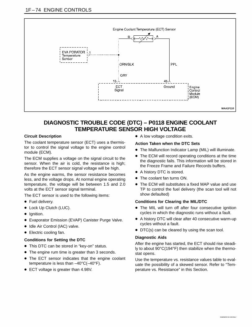
DIAGNOSTIC TROUBLE CODE (DTC) – P0118 ENGINE COOLANTTEMPERATURE SENSOR HIGH VOLTAGE
Circuit Description
The coolant temperature sensor (ECT) uses a thermis-tor to control the signal voltage to the engine controlmodule (ECM).
The ECM supplies a voltage on the signal circuit to thesensor. When the air is cold, the resistance is high;therefore the ECT sensor signal voltage will be high.
As the engine warms, the sensor resistance becomesless, and the voltage drops. At normal engine operatingtemperature, the voltage will be between 1.5 and 2.0volts at the ECT sensor signal terminal.
The ECT sensor is used to the following items:
Fuel delivery.
Lock Up Clutch (LUC).
Ignition.
Evaporator Emission (EVAP) Canister Purge Valve.
Idle Air Control (IAC) valve.
Electric cooling fan.
Conditions for Setting the DTC
This DTC can be stored in “key-on” status.
The engine rum time is greater than 3 seconds.
The ECT sensor indicates that the engine coolanttemperature is less than –40°C(–40°F).
ECT voltage is greater than 4.98V.
A low voltage condition exits.
Action Taken when the DTC Sets
The Malfunction Indicator Lamp (MIL) will illuminate.
The ECM will record operating conditions at the timethe diagnostic fails. This information will be stored inthe Freeze Frame and Failure Records buffers.
A history DTC is stored.
The coolant fan turns ON.
The ECM will substitutes a fixed MAP value and useTP to control the fuel delivery (the scan tool will notshow defaulted)
Conditions for Clearing the MIL/DTC
The MIL will turn off after four consecutive ignitioncycles in which the diagnostic runs without a fault.
A history DTC will clear after 40 consecutive warm-upcycles without a fault.
DTC(s) can be cleared by using the scan tool.
Diagnostic Aids
After the engine has started, the ECT should rise steadi-ly to about 90°C(194°F) then stabilize when the thermo-stat opens.
Use the temperature vs. resistance values table to eval-uate the possibility of a skewed sensor. Refer to “Tem-perature vs. Resistance” in this Section.

ENGINE CONTROLS 1F – 75
DAEWOO M-150 BL2
DTC P0118 – Engine Coolant Temperature Sensor High Voltage
Step Action Value(s) Yes No
1
Perform an Euro On-Board Diagnostic (EOBD)System Check.Is the system check complete?
–
Go to Step 2
Go to“On-BoardDiagnostic
System Check”
2
1. Connect the scan tool to the data link connector(DLC).
2. Run the engine until it reaches operatingtemperature.
Does the scan tool show the ECT sensor readingwithin the value specified?
80~110°C(176~230°F)
Go to“Diagnostic
Aids” Go to Step 3
3
1. Turn the ignition switch to LOCK.2. Disconnect the ECT sensor connector.3. Turn the ignition switch to ON.Does the scan tool show the ECT sensor readingwithin the value specified? ≥ -30°C Go to Step 4 Go to Step 6
4
1. Jumper the ECT sensor signal circuits at terminalB and A.
2. Turn the ignition switch to ON.Does the scan tool show the ECT sensor readingwithin the value specified?
≥180°C(356°F) Go to Step 5 Go to Step 6
5
1. Replace the ECT sensor.2. Clear any DTCs from the ECM.3. Perform the diagnostic system check.Is the replacement complete?
–
System OK
–
6
Measure the voltage between ECT terminal B andground.Does the voltage measure within the valuespecified? 4.5–5.0V Go to Step 7 Go to Step 8
7
1. Turn the ignition switch to LOCK.2. Disconnect the ECM wiring connector.3. Check for a faulty connector or terminals at the
ECT sensor connector terminal A and the ECMconnector terminal 45 for an open or short tobattery voltage.
Is the problem found?
–
Go to Step 8 Go to Step 9
8
1. Turn the ignition switch to LOCK.2. Repair the wire of the connector terminals as
needed.3. Clear any DTCs from the ECM.4. Run the engine until it reaches operating
temperature.5. Perform the diagnostic system check.Is the repair complete?
–
System OK
–
9
1. Replace the ECM.2. Run the engine until it reaches operating
temperature.3. Perform the diagnostic system check.Is the repair complete?
–
Go to Step 10
–
10Check if any additional DTCs are set.Are any DTCs displaced that have not beendiagnosed?
–Go to
applicable DTCtable System OK

1F – 76 ENGINE CONTROLS
DAEWOO M-150 BL2
MAA1F120
DIAGNOSTIC TROUBLE CODE (DTC) P0122THROTTLE POSITION SENSOR LOW VOLTAGE
Circuit Description
The Engine Control Module (ECM) supplies a 5 volt ref-erence voltage signal and a ground to the Throttle Posi-tion (TP) sensor. The TP sensor sends a voltage signalback to the ECM relative to the throttle plate opening.The voltage signal will vary from approximately 0.33volts at closed throttle, to over 4.3 volts at Wide OpenThrottle (WOT).
The TP signal is used by the ECM for fuel control and formost of the ECM controlled outputs. The TP signal isone of the most important inputs used by the ECM forfuel control and most of the ECM controlled outputs.
Conditions for Setting the DTC
TP sensor voltage indicates a throttle voltage lessthan 0.14 volts.
Action Taken When the DTC Sets
The Malfunction Indicator Lamp (MIL) will illuminate.
The ECM will record operating conditions at the timethe diagnostic fails. This information will be stored inthe Freeze Frame and Failure Records buffers.
A history DTC is stored.
The TP angle will default to 0% when the vehiclespeed is less than 3 km/h (2 mph) and 10% when thevehicle speed is greater than 3 km/h (2 mph). Thescan tool will not display the default value.
Conditions for Clearing the MIL/DTC
The MIL will turn off after four consecutive ignitioncycles in which the diagnostic runs without a fault.
A history DTC will clear after 40 consecutive warm-upcycles without a fault.
DTC(s) can be cleared by using the scan tool.
Disconnecting the ECM battery feed for more than 10seconds.
Diagnostic Aids
If the DTC P0122 cannot be duplicated, the informationincluded in the Freeze Frame data can be useful. Use ascan tool information data to determine the status of theDTC. If the dc occurs intermittently, using the Diagnostictable may help isolate the problem.

ENGINE CONTROLS 1F – 77
DAEWOO M-150 BL2
DTC P0122 – Throttle Position Sensor Low Voltage
Step Action Value(s) Yes No
1
Perform an On-Board Diagnostic (EOBD) SystemCheck.Was the check performed?
–
Go to Step 2
Go to“On-BoardDiagnostic
System Check”
2
1. Install a scan tool to the Data Link Connector(DLC).
2. Turn the ignition ON.Is the Throttle Position (TP) sensor voltage belowthe specified value? 0.20 V Go to Step 4 Go to Step 3
3
1. Turn the ignition ON.2. Review the Freeze Frame data and note the
parameters.3. Operate the vehicle within the Freeze Frame
conditions and Conditions for Setting the DTC asnoted.
Is the TP sensor voltage below the specified value? 0.20 V Go to Step 4 Go to Step 12
4
1. Turn the ignition OFF.2. Disconnect the TP sensor connector.3. Turn the ignition ON.4. Jump the 5 volt reference circuit terminal B and
the TP signal circuit terminal C at the TP sensorconnector.
Is the TP sensor voltage over the specified value? 4.0 V Go to Step 10 Go to Step 5
5
Connect a test light between B+ and the TP sensorsignal circuit terminal C.Is the TP sensor voltage greater than the specifiedvalue? 4.0 V Go to Step 6 Go to Step 8
6Check the TP sensor 5 volt reference circuit for anopen or short to ground and repair as needed.Is the repair complete?
–Go to Step 12 Go to Step 7
7
Check the 5 volt reference circuit for a poorconnection at terminal 75 of the Engine ControlModule (ECM) and repair as needed.Is the repair complete?
–
Go to Step 12 Go to Step 11
8
Check the TP sensor signal circuit between terminalC of the TP sensor and terminal 44 of the ECM foran open or a short to ground and repair as needed.Is the repair complete?
–
Go to Step 12 Go to Step 9
9
Check the TP sensor signal circuit, terminal 44 ofthe ECM for a poor connection and repair asneeded.Is the repair complete?
–
Go to Step 12 Go to Step 11
10Replace the throttle body assembly.Is the action complete?
–Go to Step 12
–
111. Turn the ignition switch OFF.2. Replace the ECM.Is the action complete?
–Go to Step 12
–

1F – 78 ENGINE CONTROLS
DAEWOO M-150 BL2
DTC P0122 – Throttle Position Sensor Low Voltage (Cont’d)
Step Action Value(s) Yes No
12
1. Using the scan tool, clear the Diagnostic TroubleCodes (DTCs).
2. Start the engine and idle at normal operatingtemperature.
3. Operate the vehicle within the Conditions forsetting this DTC as specified in the supportingtext.
Does the scan tool indicate that this diagnostic hasrun and passed?
–
Go to Step 13 Go to Step 2
13Check if any additional DTCs are set.Are any DTCs displayed that have not beendiagnosed?
–Go to
Applicable DTCTable System OK

ENGINE CONTROLS 1F – 79
DAEWOO M-150 BL2
BLANK

1F – 80 ENGINE CONTROLS
DAEWOO M-150 BL2
MAA1F120
DIAGNOSTIC TROUBLE CODE (DTC) P0123THROTTLE POSITION SENSOR HIGH VOLTAGE
Circuit Description
The Engine Control Module (ECM) supplies a 5 volt ref-erence voltage signal and a ground to the Throttle Posi-tion (TP) sensor. The TP sensor sends a voltage signalback to the ECM relative to the throttle plate opening.The voltage signal will vary from approximately 0.33volts at closed throttle, to over 4.3 volts at Wide OpenThrottle (WOT).
The TP signal is used by the ECM for fuel control and formost of the ECM controlled outputs. The TP signal isone of the most important inputs used by the ECM forfuel control and most of the ECM controlled outputs.
Conditions for Setting the DTC
TP sensor voltage indicates a throttle voltage greaterthan 4.9 volts.
Action Taken When the DTC Sets
The Malfunction Indicator Lamp (MIL) will illuminate.
The ECM will record operating conditions at the timethe diagnostic fails. This information will be stored inthe Freeze Frame and Failure Records buffers.
A history DTC is stored.
The TP angle will default to 0% when the vehiclespeed is less than 3 km/h (2 mph) and 10% when the
vehicle speed is greater than 3 km/h (2 mph). Thescan tool will not display the default value.
Conditions for Clearing the MIL/DTC
The MIL will turn off after four consecutive ignitioncycles in which the diagnostic runs without a fault.
A history DTC will clear after 40 consecutive warm-upcycles without a fault.
DTC(s) can be cleared by using the scan tool.
Disconnecting the ECM battery feed for more than 10seconds.
Diagnostic Aids
If the DTC P0123 cannot be duplicated, the informationincluded in the Freeze Frame data can be useful. Use ascan tool information data to determine the status of theDTC. If the dc occurs intermittently, using the Diagnostictable may help isolate the problem.
With ignition ON and the throttle at closed position, thevoltage should read between 0.2 and 0.90 volts and in-crease steadily to over 4.3 volts at WOT.
DTCs P0123 and P0113 stored at the same time couldbe result of an open sensor ground circuit.

ENGINE CONTROLS 1F – 81
DAEWOO M-150 BL2
DTC P0123 – Throttle Position Sensor High Voltage
Step Action Value(s) Yes No
1
Perform an On-Board Diagnostic (EOBD) SystemCheck.Was the check performed?
–
Go to Step 2
Go to“On-BoardDiagnostic
System Check”
2
1. Install a scan tool to the Data Link Connector(DLC).
2. Turn the ignition ON.Is the Throttle Position (TP) sensor voltage greaterthan the specified value? 1.0 V Go to Step 4 Go to Step 3
3
1. Turn the ignition ON.2. Review the Freeze Frame data and note the
parameters.3. Operate the vehicle within the Freeze Frame
conditions and Conditions for Setting the DTC asnoted.
Is the TP sensor voltage greater than the specifiedvalue? 3.9 V Go to Step 4 Go to Step 12
4
1. Turn the ignition OFF.2. Disconnect the TP sensor connector.3. Turn the ignition ON.Is the TP sensor voltage less than the specifiedvalue? 0.2 V Go to Step 5 Go to Step 6
5
Probe the TP sensor ground circuit, terminal A at theTP sensor connector with a test light connected toB+.Does the test light illuminate?
–
Go to Step 7 Go to Step 9
6Check the TP sensor signal circuit for an short tovoltage and repair as needed.Is the repair complete?
–Go to Step 12 Go to Step 11
7Check the 5 volt reference circuit for a short to B+and repair as needed.Is the repair complete?
–Go to Step 12 Go to Step 8
8Check the TP sensor electric connector for a poorconnection and repair as needed.Is the repair complete?
–Go to Step 12 Go to Step 10
9Check the TP sensor ground circuit for an open andrepair as needed.Is the repair complete?
–Go to Step 12 Go to Step 11
10Replace the throttle body assembly.Is the action complete?
–Go to Step 12
–
111. Turn the ignition switch OFF.2. Replace the Engine Control Module (ECM).Is the action complete?
–Go to Step 12
–
12
1. Using the scan tool, clear the Diagnostic TroubleCodes (DTCs).
2. Start the engine and idle at normal operatingtemperature.
3. Operate the vehicle within the Conditions forsetting this DTC as specified in the supportingtext.
Does the scan tool indicate that this diagnostic hasrun and passed?
–
Go to Step 13 Go to Step 2

1F – 82 ENGINE CONTROLS
DAEWOO M-150 BL2
DTC P0123 – Throttle Position Sensor High Voltage (Cont’d)
Step Action Value(s) Yes No
13Check if any additional DTCs are set.Are any DTCs displayed that have not beendiagnosed?
–Go to
Applicable DTCTable System OK

ENGINE CONTROLS 1F – 83
DAEWOO M-150 BL2
BLANK

1F – 84 ENGINE CONTROLS
DAEWOO M-150 BL2
MAA1F130
DIAGNOSTIC TROUBLE CODE (DTC) – P0131 OXYGEN SENSOR LOWVOLTAGE
Circuit Description
The engine control module (ECM) supplies a voltage ofabout 450m volts between the ECM terminals 44 and13. The oxygen (O2) sensor varies the voltage within arange of about 1volt if the exhaust is rich, down to about100mm volts if the exhaust is lean. The O2 sensor is likean open circuit and produces no voltage when it is below350°C(600°F). An open O2 sensor circuit or a cold O2
sensor causes “open loop” operation.
Conditions for Setting the DTC
(Case A)
The engine controls system is in closed loop.
Engine speed is less than 6,000rpm.
The oxygen sensor voltage is below 0.07V for at least40seconds.
DTCs P0107, P0108, P0117, P0118, P0122, P0123,P0335, P0336, P0341, P0342, P0400, P0404,P0405, P0406, P0445, P0444 are NOT SET.
(Case B)
The engine controls system is in closed loop.
Engine speed is less than 6,000rpm.
The oxygen sensor voltage is between 0.352 and0.499 at least 10seconds.
Action Taken when the DTC Sets
The Malfunction Indicator Lamp (MIL) will illuminate.
The ECM will record operating conditions at the timethe diagnostic fails. This information will be stored inthe Freeze Frame and Failure Records buffers.
A history DTC is stored.
Conditions for Clearing the MIL/DTC
The MIL will turn off after four consecutive ignitioncycles in which the diagnostic runs without a fault.
A history DTC will clear after 40 consecutive warm-upcycles without a fault.
DTC(s) can be cleared by using the scan tool.
Disconnecting the ECM battery feed for more than 10seconds.
Diagnostic Aids
Normal scan tool voltage varies between 0.1volts and0.9 volts while in closed loop.
Inspect the oxygen (O2) sensor wire. The O2 sensormay be positioned incorrectly and contacting the ex-haust manifold.
Check for an intermittent ground in the wire between theO2 sensor and the engine control module.
Perform an injector 2alance test to determine if a re-stricted fuel injector may be causing the lean condition.
Vacuum of crankcase leaks will cause a lean runningcondition.
An exhaust manifold gasket leak of a cracked exhaustmanifold may cause outside air to be pulled into the ex-haust and past the sensor.

ENGINE CONTROLS 1F – 85
DAEWOO M-150 BL2
DTC P0131 – Oxygen Sensor Low Voltage
Step Action Value(s) Yes No
1
Perform an Euro On-Board Diagnostic (EOBD)System Check.Is the system check complete?
–
Go to Step 2
Go to“On-BoardDiagnostic
System Check”
2
1. Connect the scan tool to the data linkconnector(DLC).
2. Run the engine until it reaches operatingtemperature.
3. Check for closed loop operation.Does the engine control module(ECM) go intoclosed loop?
–
Go to Step 3 Go to Step 9
3
1. Run the until until it reaches operatingtemperature?
2. Run the engine at 1,200rpm.Does the scan tool read the upstream oxygen(O2 )sensor signal voltage between the valve specified? 0.15~0.7V Go to Step 5 Go to Step 4
4Does the scan tool read the Oxygen sensor signalvoltage fixed below the valve specified?
0.01V Go to Step 7
Go To“Diagnostic
Aids”
5
1. Disconnect the Oxygen sensor connector.2. Run the warm engine at idle.Does the scan tool read the Oxygen sensor signalvoltage between the valve specified? 0.15~0.7V
Go To“Diagnostic
Aids” Go to Step 6
6
1. Turn the ignition switch to LOCK.2. Check the Oxygen sensor wire between the
Oxygen sensor and the ECM connector terminal77 and 13 is open.
Is the problem found?
–
Go to Step 8 Go to Step 11
7
1. Turn the ignition switch to LOCK.2. Check the Oxygen sensor wire between theOxygen sensor and the ECM connector terminal 77for a short to ground.Is the problem found?
–
Go to Step 8 Go to Step 11
8
1. Repair the wire or the connector terminal asneeded.
2. Clear the any DTCs from the ECM.3. Road tests the vehicle.4. Perform the diagnostic system check.Is the repair complete?
–
System OK
–
9
1. Turn the ignition switch to LOCK.2. Disconnect the Oxygen sensor connector.3. Turn the ignition switch to ON.Does the scan tool the Oxygen sensor signal voltagebetween the valve specified? 0.15~0.7V Go to Step 11 Go to Step 10
10
1. Replace the Oxygen sensor.2. Clear the DTCs from the ECM.3. Perform the diagnostic system check.Is the repair complete?
–
System OK
–
111. Replace the ECM.2. Perform the diagnostic system check.Is the repair complete?
–Go to Step 12
–
1F – 86 ENGINE CONTROLS
DAEWOO M-150 BL2
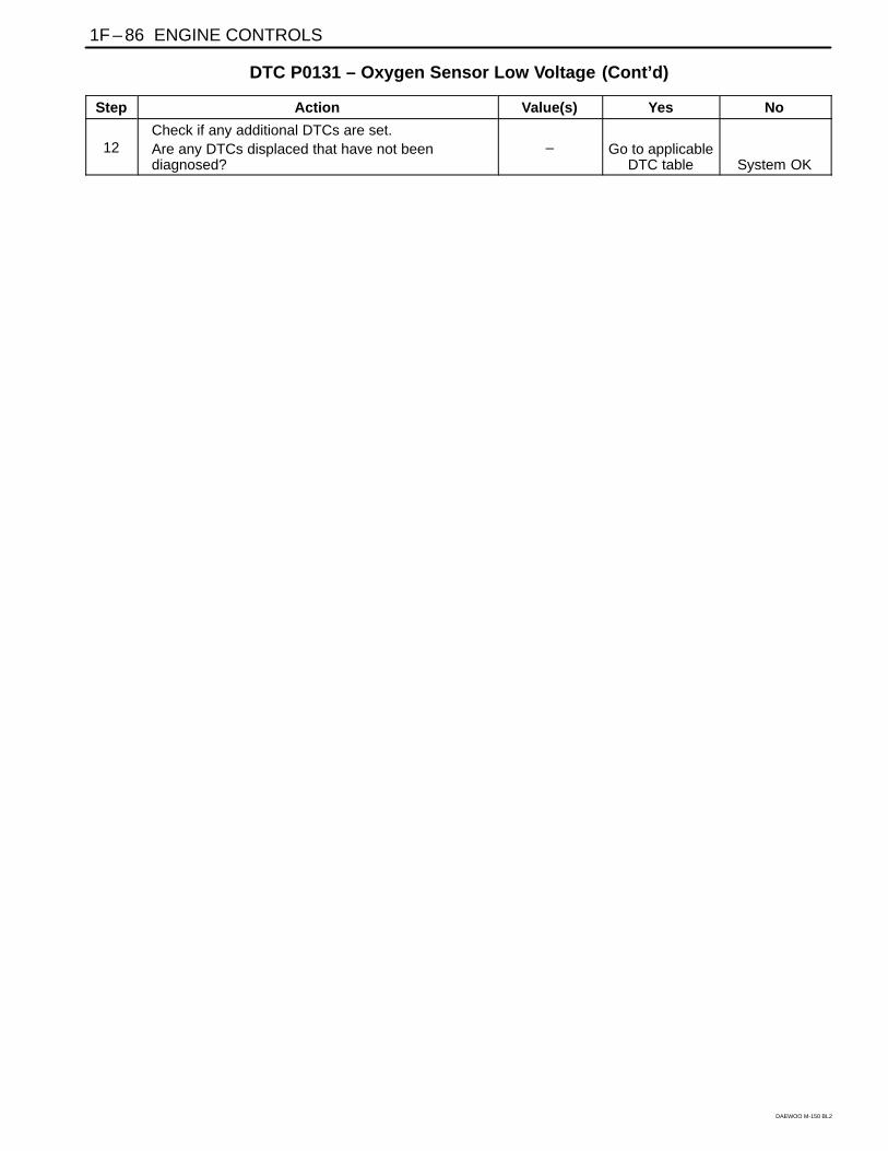
DTC P0131 – Oxygen Sensor Low Voltage (Cont’d)
Step Action Value(s) Yes No
12Check if any additional DTCs are set.Are any DTCs displaced that have not beendiagnosed?
– Go to applicableDTC table System OK

ENGINE CONTROLS 1F – 87
DAEWOO M-150 BL2
BLANK

1F – 88 ENGINE CONTROLS
DAEWOO M-150 BL2
MAA1F130
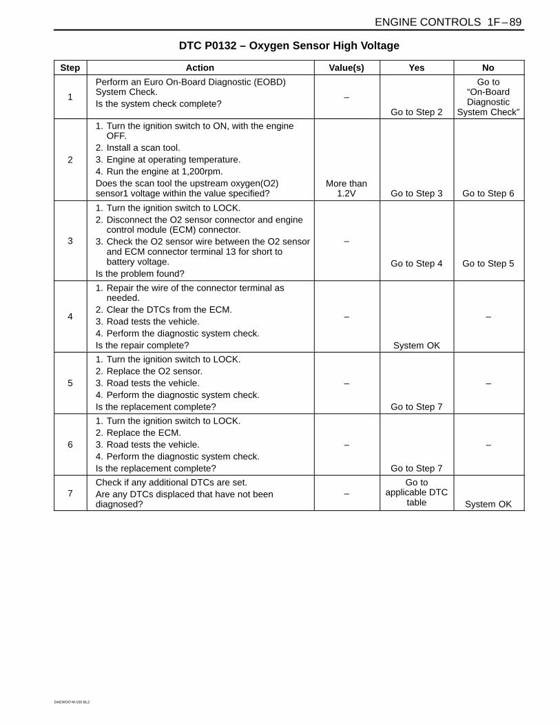
DIAGNOSTIC TROUBLE CODE (DTC) – P0132 OXYGEN SENSOR HIGHVOLTAGE
Circuit Description
The engine control module (ECM) supplies a voltage ofabout 450mm volts between the ECM terminals 44 and13. The oxygen (O2) sensor varies the voltage within arange of about 1volt if the exhaust is rich, down to about100mm volts if the exhaust is lean. The O2 sensor is likean open circuit and produces no voltage when it is below350°C(600°F). An open O2 sensor circuit or a cold O2
sensor causes “open loop” operation.
Conditions for Setting the DTC
The oxygen sensor voltage is more than 4.8V for atleast 0.2 seconds.
A high voltage condition exists.
Action Taken when the DTC Sets
The Malfunction Indicator Lamp (MIL) will illuminate.
The ECM will record operating conditions at the timethe diagnostic fails. This information will be stored inthe Freeze Frame and Records buffers.
A history DTC is stored.
Conditions for Clearing the MIL/DTC
The MIL will turn off after consecutive ignition cyclesin which the diagnostic runs without a fault.
A history DTC will clear after 40 consecutive warm upcycles without a fault.
DTC(s) can be cleared by using the scan tool.
Disconnecting the ECM battery feed for 10 seconds.
Diagnostic Aids
Normal scan tool voltage varies between 0.1volts and0.9volts while in closed loop.
Inspect the oxygen (O2) sensor wire. The O2 sensormay be positioned incorrectly and contacting the ex-haust manifold.
Check for an intermittent ground in the wire between theO2 sensor and the engine control module.
Perform an injector 2alance test to determine if a re-stricted fuel injector may be causing the lean condition.
Vacuum of crankcase leaks will cause a lean runningcondition.
An exhaust manifold gasket leak of a cracked exhaustmanifold may cause outside air to be pulled into the ex-haust and past the sensor.
ENGINE CONTROLS 1F – 89
DAEWOO M-150 BL2
DTC P0132 – Oxygen Sensor High Voltage
Step Action Value(s) Yes No
1
Perform an Euro On-Board Diagnostic (EOBD)System Check.Is the system check complete?
–
Go to Step 2
Go to“On-BoardDiagnostic
System Check”
2
1. Turn the ignition switch to ON, with the engineOFF.
2. Install a scan tool.3. Engine at operating temperature.4. Run the engine at 1,200rpm.Does the scan tool the upstream oxygen(O2)sensor1 voltage within the value specified?
More than1.2V Go to Step 3 Go to Step 6
3
1. Turn the ignition switch to LOCK.2. Disconnect the O2 sensor connector and engine
control module (ECM) connector.3. Check the O2 sensor wire between the O2 sensor
and ECM connector terminal 13 for short tobattery voltage.
Is the problem found?
–
Go to Step 4 Go to Step 5
4
1. Repair the wire of the connector terminal asneeded.
2. Clear the DTCs from the ECM.3. Road tests the vehicle.4. Perform the diagnostic system check.Is the repair complete?
–
System OK
–
5
1. Turn the ignition switch to LOCK.2. Replace the O2 sensor.3. Road tests the vehicle.4. Perform the diagnostic system check.Is the replacement complete?
–
Go to Step 7
–
6
1. Turn the ignition switch to LOCK.2. Replace the ECM.3. Road tests the vehicle.4. Perform the diagnostic system check.Is the replacement complete?
–
Go to Step 7
–
7Check if any additional DTCs are set.Are any DTCs displaced that have not beendiagnosed?
–Go to
applicable DTCtable System OK

1F – 90 ENGINE CONTROLS
DAEWOO M-150 BL2
MAA1F130
DIAGNOSTIC TROUBLE CODE (DTC) – P0133 OXYGEN SENSOR NO ACTIVITYCircuit Description
The engine control module (ECM) supplies a voltage ofabout 450mm volts between the ECM terminals 44 and13. The oxygen (O2) sensor varies the voltage within arange of about 1volt if the exhaust is rich, down to about100mm volts if the exhaust is lean. The O2 sensor is likean open circuit and produces no voltage when it is below360°C(600°F). An open O2 sensor circuit or a cold O2
sensor causes “open loop” operation.
Conditions for Setting the DTC
The engine controls system is in closed loop.
Engine Coolant Temperature is higher than 60°C(140°F).
The mass air flow(MAF) is between 75mg/tdc and100mg/tdc.
The engine speed is between 3,008rpm and3,500rpm.
The vehicle speed is between 45km/h(27.96mph)and 55km/h(34.2mph).
The manifold air pressure is higher than 90kPa.
The ignition is at 10 volts.
The upstream O2 sensor periods higher than 1.6 sec-onds.
A number of glitches higher than 5 during the test.
DTCs P0107, P0108, P0112, P0113, P0117, P0118,P0122, P0123, P0131, P0132, P0131, P0132,P0137, P0138, P1671, P0300, P0335, P0336,P0341, P0400, P0404, P0405, P0444, P0445 areNOT SET.
Action Taken when the DTC Sets
Emission related.
“Armed” after two trip with a fail.
“Disarmed” after one trip with a pass.
MIL on if failure is detected in three consecutive trips.
Stores a History DTC on the third consecutive with afail (The DTC will be armed after the second fail).
Stores a Freeze Frame on the third consecutive tripwith a fail (if empty).
Conditions for Clearing the MIL/DTC
The MIL will turn off after four consecutive ignitioncycles in which the diagnostic runs without a fault.
A history DTC will clear after 40 consecutive warm upcycles without a fault.
DTC(s) can be cleared by using the scan tool.
Diagnostic Aids
Normal scan tool voltage varies between 0.15 to 8.5mVwhile in Closed Loop. If DTC P0133 is intermittent, referto “Intermittent” in this Section.

ENGINE CONTROLS 1F – 91
DAEWOO M-150 BL2
DTC P0133 – Oxygen Sensor No Activity
Step Action Value(s) Yes No
1
Perform an Euro On-Board Diagnostic (EOBD)System Check.Is the system check complete?
–
Go to Step 2
Go to“On-BoardDiagnostic
System Check”
2
1. Connect the scan tool to the data link connector(DLC).
2. Run the engine until it reaches operatingtemperature.
3. Check for the closed loop operation.Does the scan tool indicate the closed loop?
–
Go to Step 3 Go to Step 4
3
1. Turn the ignition switch to LOCK.2. Review the freeze frame data and note the
parameters.3. Operate the vehicle within the freeze frame
conditions and Conditions for Setting the DTC.Does the scan tool indicate the closed loop?
–
Go to Step 12 Go to Step 4
4
1. Disconnect the upstream oxygen(O2) sensor connector2. Jumper the oxygen sensor connector terminal 1
to ground.3. Turn the ignition switch to ON.Does the scan tool read the oxygen sensor signalvoltage the specified valve? 0.4~0.5V Go to Step 5 Go to Step 8
5
Check the oxygen sensorconnector for malfunctionterminals or poor connection and repair asnecessary.Is repair necessary?
–
Go to Step 12 Go to Step 6
6
1. Run the engine at idle.2. Remove the jumper wire.3. Measure the voltage between the oxygen sensor
connector terminal 2 and ground.Does the oxygen sensor voltage measure above thespecified value? 0.6V Go to Step 7 Go to Step 11
7
1. Turn the ignition switch to LOCK2. Measure the voltage between the upstream O2
sensor connector terminal 2 and ground.Does the oxygen sensor voltage measure above thespecified value? 0.3V Go to Step 9 Go to Step 11
8
Repair the wire or the connector between the upstreO2 sensor terminal 1 and the engine control module(ECM) terminal 13 is open or a short to ground.Is the repair complete?
–
Go to Step 11 Go to Step 9
9
Repair the wire and the connector terminal betweenthe oxygen sensor connector terminal 2 and theECM connector terminal 77 is open or a short toground.Is the repair complete?
–
Go to Step 12 Go to Step 10
10
1. Turn the ignition switch to LOCK2. Replace the ECM.3. Perform the diagnostic system check.Is the repair complete?
–
System OK
–

1F – 92 ENGINE CONTROLS
DAEWOO M-150 BL2
DTC P0133 – Oxygen Sensor No Activity (Cont’d)
Step Action Value(s) Yes No
11Replace the O2 sensor.Is the repair complete?
–Go to Step 12
–
121. Clear any DTCs from the ECM2. Perform the diagnostic system checkIs the repair complete
–Go to Step 13
–
13Check if any additional DTCs are set.Are any DTCs displaced that have not beendiagnosed?
– Go to applicableDTC table System OK

ENGINE CONTROLS 1F – 93
DAEWOO M-150 BL2
BLANK
1F – 94 ENGINE CONTROLS
DAEWOO M-150 BL2
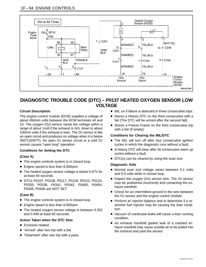
MAA1F140
DIAGNOSTIC TROUBLE CODE (DTC) – P0137 HEATED OXYGEN SENSOR LOWVOLTAGE
Circuit Description
The engine control module (ECM) supplies a voltage ofabout 450mm volts between the ECM terminals 44 and13. The oxygen (O2) sensor varies the voltage within arange of about 1volt if the exhaust is rich, down to about100mm volts if the exhaust is lean. The O2 sensor is likean open circuit and produces no voltage when it is below360°C(600°F). An open O2 sensor circuit or a cold O2
sensor causes “open loop” operation.
Conditions for Setting the DTC
(Case A)
The engine controls system is in closed loop.
Engine speed is less than 6,000rpm.
The heated oxygen sensor voltage is below 0.07V forat least 40 seconds.
DTCs P0107, P0108, P0117, P0118, P0122, P0123,P0335, P0336, P0341, P0342, P0400, P0404,P0405, P0406 are NOT SET.
(Case B)
The engine controls system is in closed loop.
Engine speed is less than 6,000rpm.
The heated oxygen sensor voltage is between 0.352and 0.499 at least 60 seconds.
Action Taken when the DTC Sets
Emission related.
“Armed” after two trip with a fail.
“Disarmed” after one trip with a pass.
MIL on if failure is detected in three consecutive trips.
Stores a History DTC on the third consecutive with afail (The DTC will be armed after the second fail).
Stores a Freeze Frame on the third consecutive tripwith a fail (if empty).
Conditions for Clearing the MIL/DTC
The MIL will turn off after four consecutive ignitioncycles in which the diagnostic runs without a fault.
A history DTC will clear after 40 consecutive warm upcycles without a fault.
DTC(s) can be cleared by using the scan tool.
Diagnostic Aids
Normal scan tool voltage varies between 0.1 voltsand 0.9 volts while in closed loop.
Inspect the oxygen (O2) sensor wire. The O2 sensormay be positioned incorrectly and contacting the ex-haust manifold.
Check for an intermittent ground in the wire betweenthe O2 sensor and the engine control module.
Perform an injector balance test to determine if a re-stricted fuel injector may be causing the lean condi-tion.
Vacuum of crankcase leaks will cause a lean runningcondition.
An exhaust manifold gasket leak of a cracked ex-haust manifold may cause outside air to be pulled intothe exhaust and past the sensor.
ENGINE CONTROLS 1F – 95
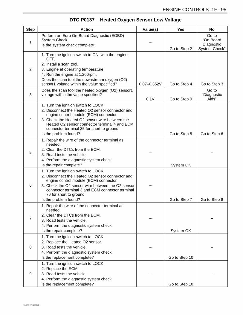
DAEWOO M-150 BL2
DTC P0137 – Heated Oxygen Sensor Low Voltage
Step Action Value(s) Yes No
1
Perform an Euro On-Board Diagnostic (EOBD)System Check.Is the system check complete?
–
Go to Step 2
Go to“On-BoardDiagnostic
System Check”
2
1. Turn the ignition switch to ON, with the engineOFF.
2. Install a scan tool.3. Engine at operating temperature.4. Run the engine at 1,200rpm.Does the scan tool the downstream oxygen (O2)sensor1 voltage within the value specified? 0.07–0.352V Go to Step 4 Go to Step 3
3Does the scan tool the heated oxygen (O2) sensor1voltage within the value specified?
0.1V Go to Step 9
Go to“Diagnostic
Aids”
4
1. Turn the ignition switch to LOCK.2. Disconnect the Heated O2 sensor connector and
engine control module (ECM) connector.3. Check the Heated O2 sensor wire between the
Heated O2 sensor connector terminal 4 and ECMconnector terminal 35 for short to ground.
Is the problem found?
–
Go to Step 5 Go to Step 6
5
1. Repair the wire of the connector terminal asneeded.
2. Clear the DTCs from the ECM.3. Road tests the vehicle.4. Perform the diagnostic system check.Is the repair complete?
–
System OK
–
6
1. Turn the ignition switch to LOCK.2. Disconnect the Heated O2 sensor connector and
engine control module (ECM) connector.3. Check the O2 sensor wire between the O2 sensor
connector terminal 3 and ECM connector terminal76 for short to ground.
Is the problem found?
–
Go to Step 7 Go to Step 8
7
1. Repair the wire of the connector terminal asneeded.
2. Clear the DTCs from the ECM.3. Road tests the vehicle.4. Perform the diagnostic system check.Is the repair complete?
–
System OK
–
8
1. Turn the ignition switch to LOCK.2. Replace the Heated O2 sensor.3. Road tests the vehicle.4. Perform the diagnostic system check.Is the replacement complete?
–
Go to Step 10
–
9
1. Turn the ignition switch to LOCK.2. Replace the ECM.3. Road tests the vehicle.4. Perform the diagnostic system check.Is the replacement complete?
–
Go to Step 10
–

1F – 96 ENGINE CONTROLS
DAEWOO M-150 BL2
DTC P0137 – Heated Oxygen Sensor Low Voltage (Cont’d)
Step Action Value(s) Yes No
10Check if any additional DTCs are set.Are any DTCs displaced that have not beendiagnosed?
–Go to
applicable DTCtable System OK

ENGINE CONTROLS 1F – 97
DAEWOO M-150 BL2
BLANK

1F – 98 ENGINE CONTROLS
DAEWOO M-150 BL2
MAA1F140
DIAGNOSTIC TROUBLE CODE (DTC) – P0138 HEATED OXYGEN SENSOR HIGHVOLTAGE
Circuit Description
The engine control module (ECM) supplies a voltage ofabout 450mm volts between the ECM terminals 64 and13. The Heated oxygen (O2) sensor varies the voltagewithin a range of about 1volt if the exhaust is rich, downto about 100mm volts if the exhaust is lean. The HeatedO2 sensor is like an open circuit and produces no volt-age when it is below 360°C(600°F). An open O2 sensorcircuit or a cold O2 sensor causes “open loop” operation.
Conditions for Setting the DTC
The Heated oxygen sensor voltage is more than 4.8Vfor at least 0.2 seconds.
A high voltage condition exists.
Action Taken when the DTC Sets
Emission related.
“Armed” after two trip with a fail.
“Disarmed” after one trip with a pass.
MIL on if failure is detected in three consecutive trips.
Stores a History DTC on the third consecutive with afail (The DTC will be armed after the second fail).
Stores a Freeze Frame on the third consecutive tripwith a fail (if empty).
Conditions for Clearing the MIL/DTC
The MIL will turn off after four consecutive ignitioncycles in which the diagnostic runs without a fault.
A history DTC will clear after 40 consecutive warm upcycles without a fault.
DTC(s) can be cleared by using the scan tool.
Diagnostic Aids
Normal scan tool voltage varies between 0.1volts and0.9volts while in closed loop.
Inspect the oxygen (O2) sensor wire. The O2 sensormay be positioned incorrectly and contacting the ex-haust manifold.
Check for an intermittent ground in the wire betweenthe O2 sensor and the engine control module.
Perform an injector 2alance test to determine if a re-stricted fuel injector may be causing the lean condi-tion.
Vacuum of crankcase leaks will cause a lean runningcondition.
An exhaust manifold gasket leak of a cracked ex-haust manifold may cause outside air to be pulled intothe exhaust and past the sensor.

ENGINE CONTROLS 1F – 99
DAEWOO M-150 BL2
DTC P0138 – Heated Oxygen Sensor High Voltage
Step Action Value(s) Yes No
1
Perform an Euro On-Board Diagnostic (EOBD)System Check.Is the system check complete?
–
Go to Step 2
Go to“On-BoardDiagnostic
System Check”
2
1. Turn the ignition switch to ON, with the engineOFF.
2. Install a scan tool.3. Engine at operating temperature.4. Run the engine at 1,200rpm.Does the scan tool the Heated oxygen(O2) sensorvoltage within the value specified?
More than1.2V Go to Step 3 Go to Step 6
3
1. Turn the ignition switch to LOCK.2. Disconnect the Heated O2 sensor connector and
engine control module (ECM) connector.3. Check the Heated O2 sensor wire between the
Heated O2 sensor connector terminal 4 and ECMconnector terminal 35 for an open or short tobattery voltage.
Is the problem found?
–
Go to Step 4 Go to Step 5
4
1. Repair the wire of the connector terminal asneeded.
2. Clear the DTCs from the ECM.3. Road tests the vehicle.4. Perform the diagnostic system check.Is the repair complete?
–
System OK
–
5
1. Turn the ignition switch to LOCK.2. Replace the Heated O2 sensor.3. Road tests the vehicle.4. Perform the diagnostic system check.Is the replacement complete?
–
Go to Step 7
–
6
1. Turn the ignition switch to LOCK.2. Replace the ECM.3. Road tests the vehicle.4. Perform the diagnostic system check.Is the replacement complete?
–
Go to Step 7
–
7Check if any additional DTCs are set.Are any DTCs displaced that have not beendiagnosed?
–Go to
applicable DTCtable System OK

1F – 100 ENGINE CONTROLS
DAEWOO M-150 BL2
MAA1F140
DIAGNOSTIC TROUBLE CODE (DTC) – P0140 HEATED OXYGEN SENSOR NOACTIVITY
Circuit Description
The engine control module (ECM) supplies a voltage ofabout 450mm volts between the ECM terminals 64 and13. The oxygen (O2) sensor varies the voltage within arange of about 1volt if the exhaust is rich, down to about100mm volts if the exhaust is lean. The O2 sensor is likean open circuit and produces no voltage when it is below360°C(600°F). An open O2 sensor circuit or a cold O2
sensor causes “open loop” operation.
Conditions for Setting the DTC
The engine controls system is in closed loop.
Engine Coolant Temperature is higher than 70°C(140°F).
The mass air flow(MAF) is between 25kg/h and50kg/h.
The engine speed is between 2,400rpm and 300rpm.
The vehicle speed is between 64km/h(12.4mph) and80km/h(24.9mph).
The manifold air pressure is higher than 70kPa.
The ignition is at 10 volts.
No transition from rich side to lean side or lean side torich side during 7.8 seconds even with a forcing of O2
sensor controller.
DTCs P0107, P0108, P0112, P0113, P0117, P0118,P0122, P0123, P0137, P0138, P0137, P0138,
P0137, P0138, P1671, P0300, P0335, P0336,P0341, P0400, P0404, P0405, P0644, P0645 areNOT SET.
Action Taken when the DTC Sets
Emission related.
“Armed” after two trip with a fail.
“Disarmed” after one trip with a pass.
MIL on if failure is detected in three consecutive trips.
Stores a History DTC on the third consecutive with afail (The DTC will be armed after the second fail).
Stores a Freeze Frame on the third consecutive tripwith a fail (if empty).
Conditions for Clearing the MIL/DTC
The MIL will turn off after four consecutive ignitioncycles in which the diagnostic runs without a fault.
A history DTC will clear after 40 consecutive warm upcycles without a fault.
DTC(s) can be cleared by using the scan tool.
Disconnecting the ECM battery feed for 10 seconds.
Diagnostic Aids
Normal scan tool voltage varies between 0.15 to8.5mV while in Closed Loop. If DTC P0140 is inter-mittent, refer to “Intermittent” in this Section.

ENGINE CONTROLS 1F – 101
DAEWOO M-150 BL2
DTC P0140 – Heated Oxygen Sensor No Activity
Step Action Value(s) Yes No
1
Perform an Euro On-Board Diagnostic (EOBD)System Check.Is the system check complete?
–
Go to Step 2
Go to“On-BoardDiagnostic
System Check”
2
1. Run the engine to above the specified operatingtemperature.
2. Install a scan tool.3. Operate the engine above the specified rpm for
2minuets.Does the scan tool the indicate Closed Loop?
80°C(176°F)1,200 rpm Go to Step 3 Go to Step 4
3
1. Turn the Turn the ignition switch to ON.2. Review the Freeze Frame data and note the
parameters.3. Operate the vehicle within the freeze frame
conditions and Conditions for Setting the DTC asnoted?
Does the scan tool the indicate Closed Loop?
–
Go to Step 12 Go to Step 4
4
Disconnect the Heated O2 sensor connector andjumper the Heated O2 sensor low circuit, terminal 4to ground.Is the HO2 voltage below the specified value anddoes the scan tool indicate the heated oxygensensor heater voltage within the specified value? 0.5V Go to Step 5 Go to Step 6
5
Check the Heated O2 sensor connector formalfunction terminals or poor connection and repairas necessary.Is repair necessary?
–
Go to Step 12 Go to Step 9
6
1. Turn the ignition switch to On.2. Remove the jumper wire.3. Using a digital voltmeter(DVM), measure the
voltage between the Heated O2 sensor signalcircuit, terminal 3 to ground.
Does the Heated O2 sensor voltage measure abovethe specified value? 0.6V Go to Step 10 Go to Step 9
7 Does the Heated O2 sensor voltage measure belowthe specified value? 0.3V Go to Step 11 Go to Step 8
8
Check the Heated O2 sensor ground circuit, terminal4 for an open or poor connection and repair asnecessary.Is repair necessary?
–
Go to Step 12 Go to Step 8
11
Check the Heated O2 sensor signal circuit, terminal3 for an open or poor connection and repair asnecessary.Is repair necessary?
–
Go to Step 12 Go to Step 8
10
1. If disconnected, reconnect Heated O2 sensorconnector.
2. Using the scan tool, clear the DTCs.3. Start the engine and idle at normal operating
temperature.4. Operate the vehicle within the conditions for
setting this DTC as specified in the supportingtext.
Does the scan tool indicated that this diagnostic hasrun and passed?
–
Go to Step 13 Go to Step 2

1F – 102 ENGINE CONTROLS
DAEWOO M-150 BL2
DTC P0140 – Heated Oxygen Sensor No Activity (Cont’d)
Step Action Value(s) Yes No
11
1. Turn the ignition switch to LOCK.2. Replace the Heated O2 sensor.3. Road tests the vehicle.4. Perform the diagnostic system check.Is the replacement complete?
–
Go to Step 15
–
12
1. Turn the ignition switch to LOCK.2. Replace the ECM.3. Road tests the vehicle.4. Perform the diagnostic system check.Is the replacement complete?
–
Go to Step 15
–
13Check if any additional DTCs are set.Are any DTCs displaced that have not beendiagnosed?
–Go to
applicable DTCtable System OK

ENGINE CONTROLS 1F – 103
DAEWOO M-150 BL2
BLANK

1F – 104 ENGINE CONTROLS
DAEWOO M-150 BL2
MAA1F140
DIAGNOSTIC TROUBLE CODE (DTC) – P0141 HEATED OXYGEN SENSORHEATER MALFUNCTION
Circuit Description
The engine control module (ECM) supplies a voltage ofabout 450mm volts between the ECM terminals 44 and13. The oxygen (O2) sensor varies the voltage within arange of about 1volt if the exhaust is rich, down to about100mm volts if the exhaust is lean. The O2 sensor is likean open circuit and produces no voltage when it is below360°C(600°F). An open O2 sensor circuit or a cold O2
sensor causes “open loop” operation.
Conditions for Setting the DTC
Heated oxygen sensor 5V reference voltage supplycircuit high voltage or ground.
Heated oxygen sensor 5V reference voltage supplycircuit open.
Action Taken when the DTC Sets
Emission related.
“Armed” after two trip with a fail.
“Disarmed” after one trip with a pass.
MIL on if failure is detected in three consecutive trips.
Stores a History DTC on the third consecutive with afail (The DTC will be armed after the second fail).
Stores a Freeze Frame on the third consecutive tripwith a fail (if empty).
Conditions for Clearing the MIL/DTC
The MIL will turn off after four consecutive ignitioncycles in which the diagnostic runs without a fault.
A history DTC will clear after 40 consecutive warm upcycles without a fault.
DTC(s) can be cleared by using the scan tool.
Diagnostic Aids
Normal scan tool voltage varies between 0.1volts and0.9 volts while in closed loop.
Inspect the oxygen (O2) sensor wire. The O2 sensormay be positioned incorrectly and contacting the ex-haust manifold.
Check for an intermittent ground in the wire betweenthe O2 sensor and the engine control module.
Perform an injector 2alance test to determine if a re-stricted fuel injector may be causing the lean condi-tion.
Vacuum of crankcase leaks will cause a lean runningcondition.
An exhaust manifold gasket leak of a cracked ex-haust manifold may cause outside air to be pulled intothe exhaust and past the sensor.
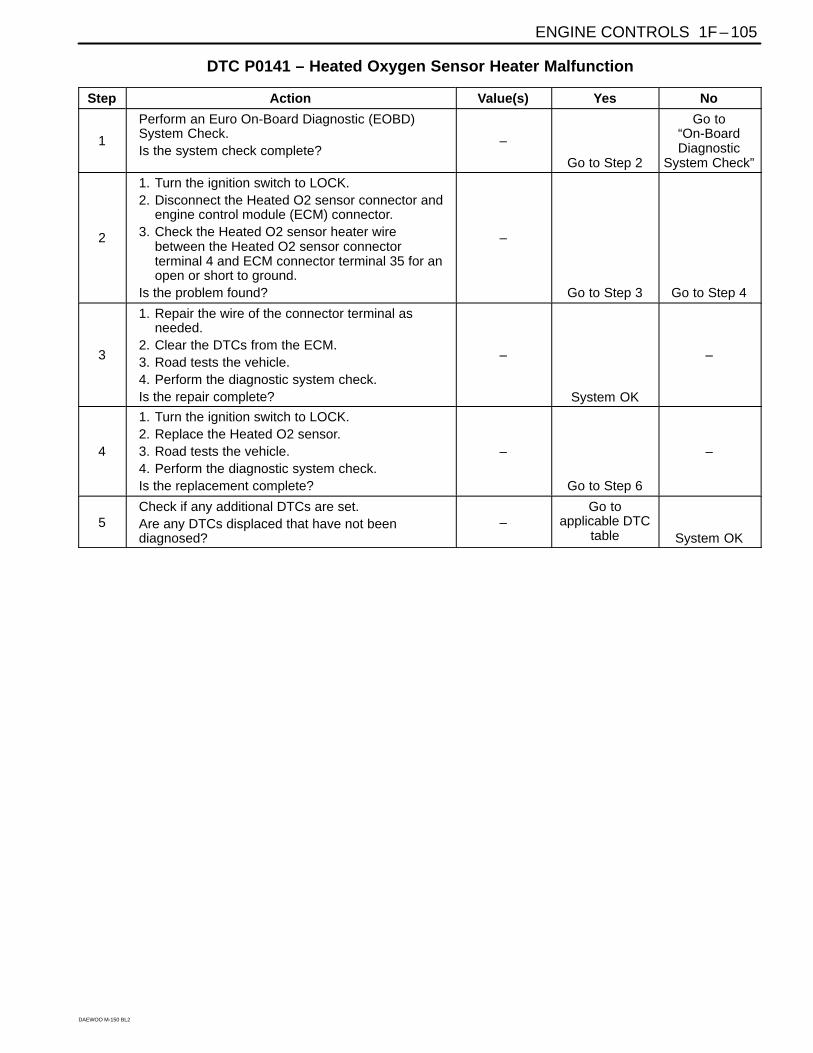
ENGINE CONTROLS 1F – 105
DAEWOO M-150 BL2
DTC P0141 – Heated Oxygen Sensor Heater Malfunction
Step Action Value(s) Yes No
1
Perform an Euro On-Board Diagnostic (EOBD)System Check.Is the system check complete?
–
Go to Step 2
Go to“On-BoardDiagnostic
System Check”
2
1. Turn the ignition switch to LOCK.2. Disconnect the Heated O2 sensor connector and
engine control module (ECM) connector.3. Check the Heated O2 sensor heater wire
between the Heated O2 sensor connectorterminal 4 and ECM connector terminal 35 for anopen or short to ground.
Is the problem found?
–
Go to Step 3 Go to Step 4
3
1. Repair the wire of the connector terminal asneeded.
2. Clear the DTCs from the ECM.3. Road tests the vehicle.4. Perform the diagnostic system check.Is the repair complete?
–
System OK
–
4
1. Turn the ignition switch to LOCK.2. Replace the Heated O2 sensor.3. Road tests the vehicle.4. Perform the diagnostic system check.Is the replacement complete?
–
Go to Step 6
–
5Check if any additional DTCs are set.Are any DTCs displaced that have not beendiagnosed?
–Go to
applicable DTCtable System OK

1F – 106 ENGINE CONTROLS
DAEWOO M-150 BL2
DIAGNOSTIC TROUBLE CODE (DTC) – P0171 FUEL TRIM SYSTEM TOO LEANSystem Description
To provide the best possible combination of driveability,fuel economy, and emission control, a Closed Loop air/fuel metering system is used. While in Closed Loop, theEngine Control Module (ECM) monitors the oxygen sen-sor (O2S) signal voltage and adjusts fuel delivery basedon signal voltage. A change made to fuel delivery will beindicated by the long and short term fuel trim valueswhich can be monitored with the scan tool. Ideal fuel trimvalues are around 128 (0%). If the O2S signal is indicat-ing a lean condition, the ECM will add fuel resulting infuel trim values above 128 (0% to 100%). If a rich condi-tion is detected, the fuel trim values will be below 128(0% to –100%), indicating that the ECM is reducing theamount of fuel delivered. If exhaust emissions reach anexcessive level due to a lean or rich condition, a fuel trimDiagnostic Trouble Code (DTC) is set.
Conditions for Setting the DTC
No intrusive tests active.
DTCs P0106, P0107, P0108, P0112, P0113, P0117,P0118, P0122, P0123, P0125, P0131, P0132,P0133, P0134, P0137, P0138, P0140, P0141,P1167, P1171, P0201, P0202, P0203, P0204,P0300, P0336, P0337, P0341, P0342, P0402,P0404, P1404, P0405, P0406, P0443, P0506, andP0507are not set.
The average of short term fuel trim value is greaterthan or equal to 120.
Throttle Position (TP) is less than 95%.
Engine speed is between 700 and 6000 rpm.
Barometric Pressure (BARO) is greater than 92.0kPa (10.4 psi).
Coolant temperature is between 80°C (176°F) and115°C (239°F).
Manifold Absolute Pressure (MAP) is more than 90kPa (10.2 psi).
System is in closed loop.
Adaptive index is ready.
Action Taken when the DTC Sets
Emission related.
“Armed” after two trip with a fail.
“Disarmed” after one trip with a pass.
MIL on if failure is detected in three consecutive trips.
Stores a History DTC on the third consecutive with afail (The DTC will be armed after the second fail).
Stores a Freeze Frame on the third consecutive tripwith a fail (if empty).
Conditions for Clearing the MIL/DTC
The MIL will turn off after four consecutive ignitioncycles in which the diagnostic runs without a fault.
A history DTC will clear after 40 consecutive warm upcycles without a fault.
DTC(s) can be cleared by using the scan tool.
Diagnostic Aids
Important: After repairs, use the scan tool Fuel TrimReset function to reset the long-term fuel trim to 128(0%).
Fuel pressure – The system will be lean if the pres-sure is too low. It may be necessary to monitor fuelpressure while driving the vehicle at various roadspeeds and/or loads to confirm.
Map sensor – An output that causes the ECM tosense a lower than normal manifold pressure (highvacuum) can cause the system to go lean. Discon-necting the MAP sensor will allow the ECM to substi-tute a fixed (default) value for the MAP sensor. If thelean condition is gone when the sensor is discon-nected, substitute a known good sensor and recheck.
Fuel contamination – Water, in even small amounts,near the in-tank fuel pump inlet can be delivered tothe injector. The water causes a lean exhaust andcan set DTC P0171.
Check for poor O2S or MAP sensor connection at theECM. Inspect the harness connectors for the followingconditions:
Backed-out terminals
Improper mating
Broken locks
Improperly formed
Damaged terminals
Poor terminal-to-wire connection
Inspect the wiring harness for damage. If the harnessappears to be OK, observe the O2S display on the scantool while moving the connectors and the wiring harnessrelated to the engine harness. A change in the displaywill indicate the location of the fault.
Check the brake power booster check valve for possibleleaks.

ENGINE CONTROLS 1F – 107
DAEWOO M-150 BL2
DTC P0171 – Fuel Trim System Too Lean
Step Action Value(s) Yes No
1
Perform an Euro On-Board Diagnostic (EOBD)System Check.Is the system check complete?
–
Go to Step 2
Go to“On-BoardDiagnostic
System Check”
2
1. Install the scan tool to the Data Link Connector(DLC).
2. Turn the ignition ON.Are any component related Diagnostic TroubleCodes (DTCs) set?
– Go toApplicable DTC
table Go to Step 3
3
With the engine running, operate the vehicle until theLOOP STATUS indicates closed.Is the Long Term Fuel Trim value below thespecified value? –22% Go to Step 4 Go to Step 5
4
1. Turn the ignition switch ON, with the engine OFF.2. Review the Freeze Frame data and note the
parameters.3. Operate the vehicle within the Freeze Frame
conditions and Conditions for Setting The DTC asnoted.
Does the Long Term Fuel Trim value go below thespecified value while operating under the specifiedconditions? –22% Go to Step 16 Go to Step 5
5
Visually/physically check the following items: Vacuum hoses for splits, kinks and improper
connections. Crankcase ventilation oil/air separator for proper
installation. Exhaust system for corrosion, leaks, loose or
missing hardware. Oxygen sensor (O2S) is installed securely and
the pigtail harness is not contacting exhaustmanifold or engine.
Fuel for excessive water, alcohol, or othercontaminants.
Engine Control Module (ECM) and sensorgrounds are clean, tight, and in their properlocations.
Do any of the above checks isolate a conditionrequiring repair?
–
Go to Step 7 Go to Step 6
6
1. Disconnect the Manifold Absolute Pressure(MAP) sensor electrical connector.
2. Operate the vehicle in Closed Loop whilemonitoring the Long Term Fuel Trim value.
Is the Long Term Fuel Trim value below thespecified value? –22% Go to Step 15 Go to Step 9
7
1. Repair the malfunction found in Step 5.2. Recheck the Long Term Fuel Trim value while
operating the engine.Is the Long Term Fuel Trim value below thespecified value? –22% Go to Step 8 Go to Step 9
8Lean condition is not present.Does a driveability problem exist? –
Go to“SymptomDiagnosis” Go to Step 16

1F – 108 ENGINE CONTROLS
DAEWOO M-150 BL2
DTC P0171 – Fuel Trim System Too Lean (Cont’d)
Step Action Value(s) Yes No
9
1. Visually/physically inspect the following items forvacuum leaks: Intake manifold. Throttle body. Injector O-rings.
2. Repair any leaks found as necessary.Is the repair complete?
–
Go to Step 16 Go to Step 16
10Allow the engine to idle.Are the Idle Air Control (IAC) counts above thespecified value? 5 Go to Step 11 Go to Step 12
11
Check the fuel for excessive water, alcohol, or othercontaminants and correct the contaminated fuelcondition if present.Is the repair complete?
–
Go to Step 16 Go to Step 13
12
Check the IAC valve performance. Refer to “DTCP0506 Idle Speed RPM Lower Than Desired IdleSpeed” or “DTC P0507 Idle Speed RPM HigherThan Desired Idle Speed” in this section and repairas necessary.Is the repair complete?
–
Go to Step 16 Go to Step 13
13
1. Connect a fuel pressure gauge to the fuel system.2. Turn the ignition OFF for at least 10 seconds.3. Turn the ignition ON, with the engine OFF. The
fuel pump will run for approximately 2–3 seconds.It may be necessary to cycle the ignition switchON more than once to obtain maximum fuelpressure.
4. Note the fuel pressure with the fuel pump running.The pressure should be within the specified value.When the fuel pump stops, the pressure may varyslightly then hold steady.
Is the fuel pressure steady and does the fuelpressure hold?
380 KPa(55 psi) Go to Step 14
Go to“Fuel System
Diagnosis”
14
1. Start and idle the engine at normal operatingtemperature.
2. The fuel pressure noted in the above step shoulddrop by the indicated value.
Does the fuel pressure drop by the indicated value?21–69 KPa(3–10 psi)
Go to“Fuel Injector2alance Test”
Go to“Fuel System
Diagnosis”
15Replace the MAP sensor.Is the action complete?
–Go to Step 16
–
16
1. Using the scan tool, clear the Diagnostic TroubleCodes (DTCs).
2. Start the engine and idle at normal operatingtemperature.
3. Operate the vehicle within the Conditions forsetting this DTC as specified in the supportingtext.
Does the scan tool indicate that this diagnostic hasrun and passed?
–
Go to Step 17 Go to Step 2
17Check if any additional DTCs are set.Are any DTCs displayed that have not beendiagnosed?
–Go to
applicable DTCtable System OK

ENGINE CONTROLS 1F – 109
DAEWOO M-150 BL2
DIAGNOSTIC TROUBLE CODE (DTC) – P0172 FUEL TRIM SYSTEM TOO RICHSystem Description
To provide the best possible combination of driveability,fuel economy, and emission control, a Closed Loop air/fuel metering system is used. While in Closed Loop, theEngine Control Module (ECM) monitors the oxygen sen-sor (O2S) signal voltage and adjusts fuel delivery basedon signal voltage. A change made to fuel delivery will beindicated by the long and short term fuel trim valueswhich can be monitored with the scan tool. Ideal fuel trimvalues are around 128 (0%). If the O2S signal is indicat-ing a lean condition, the ECM will add fuel resulting infuel trim values above 128 (0% to 100%). If a rich condi-tion is detected, the fuel trim values will be below 128(0% to –100%), indicating that the ECM is reducing theamount of fuel delivered. If exhaust emissions reach anexcessive level due to a lean or rich condition, a fuel trimDiagnostic Trouble Code (DTC) is set.
Conditions for Setting the DTC
No intrusive tests active.
DTCs P0106, P0107, P0108, P0112, P0113, P0117,P0118, P0122, P0123, P0131, P0132, P0133,P0134, P0137, P0138, P1167, P1171, P0300,P0336, P0337, P0341, P0342, P0402, P0404,P1404, P0405, P0406, P0443, P0506, and P0507arenot set.
The average of short term fuel trim value is greaterthan or equal to 120.
Throttle Position (TP) is less than 95%.
Engine speed is between 700 and 6000 rpm.
Barometric Pressure (BARO) is greater than 90.0kPa (10.4 psi).
Coolant temperature is between 80°C (176°F) and115°C (239°F).
Manifold Absolute Pressure (MAP) is more than 70kPa (10.2 psi).
System is in closed loop.
Adaptive index is ready.
Action Taken when the DTC Sets
Emission related.
“Armed” after two trip with a fail.
“Disarmed” after one trip with a pass.
MIL on if failure is detected in three consecutive trips.
Stores a History DTC on the third consecutive with afail (The DTC will be armed after the second fail).
Stores a Freeze Frame on the third consecutive tripwith a fail (if empty).
Conditions for Clearing the MIL/DTC
The MIL will turn off after four consecutive ignitioncycles in which the diagnostic runs without a fault.
A history DTC will clear after 40 consecutive warm upcycles without a fault.
DTC(s) can be cleared by using the scan tool.
Diagnostic Aids
Important: After repairs, use the scan tool Fuel TrimReset function to reset the long-term fuel trim to 128(0%).
Check for poor connection at the ECM. Inspect the har-ness connectors for the following conditions:
Backed-out terminals.
Improper mating.
Broken locks.
Improperly formed.
Damaged terminals.
Poor terminal-to-wire connection.
Inspect the wiring harness for damage. If the harnessappears to be OK, observe the O2S display on the scantool while moving the connectors and the wiring harnessrelated to the engine harness. A change in the displaywill indicate the location of the fault.
If a DTC P1404 is also set, check the 5 volt referencecircuits for a short to voltage.
Check for a restricted exhaust system.
A shorted 5 volt reference circuit may cause a DTCP0172 to set. Check the 5 volt reference sensors for ab-normal readings.
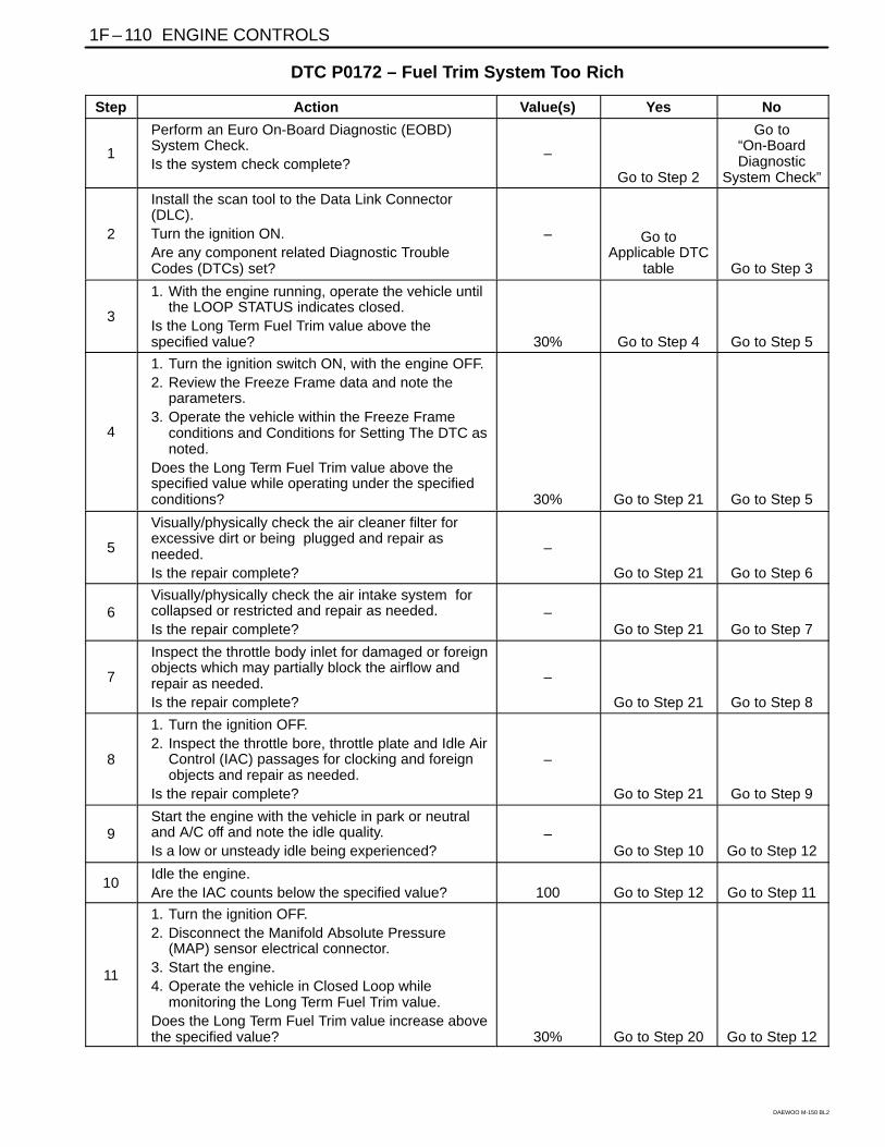
1F – 110 ENGINE CONTROLS
DAEWOO M-150 BL2
DTC P0172 – Fuel Trim System Too Rich
Step Action Value(s) Yes No
1
Perform an Euro On-Board Diagnostic (EOBD)System Check.Is the system check complete?
–
Go to Step 2
Go to“On-BoardDiagnostic
System Check”
2
Install the scan tool to the Data Link Connector(DLC).Turn the ignition ON.Are any component related Diagnostic TroubleCodes (DTCs) set?
– Go toApplicable DTC
table Go to Step 3
3
1. With the engine running, operate the vehicle untilthe LOOP STATUS indicates closed.
Is the Long Term Fuel Trim value above thespecified value? 30% Go to Step 4 Go to Step 5
4
1. Turn the ignition switch ON, with the engine OFF.2. Review the Freeze Frame data and note the
parameters.3. Operate the vehicle within the Freeze Frame
conditions and Conditions for Setting The DTC asnoted.
Does the Long Term Fuel Trim value above thespecified value while operating under the specifiedconditions? 30% Go to Step 21 Go to Step 5
5
Visually/physically check the air cleaner filter forexcessive dirt or being plugged and repair asneeded.Is the repair complete?
–
Go to Step 21 Go to Step 6
6Visually/physically check the air intake system forcollapsed or restricted and repair as needed.Is the repair complete?
–Go to Step 21 Go to Step 7
7
Inspect the throttle body inlet for damaged or foreignobjects which may partially block the airflow andrepair as needed.Is the repair complete?
–
Go to Step 21 Go to Step 8
8
1. Turn the ignition OFF.2. Inspect the throttle bore, throttle plate and Idle Air
Control (IAC) passages for clocking and foreignobjects and repair as needed.
Is the repair complete?
–
Go to Step 21 Go to Step 9
9Start the engine with the vehicle in park or neutraland A/C off and note the idle quality.Is a low or unsteady idle being experienced?
–Go to Step 10 Go to Step 12
10Idle the engine.Are the IAC counts below the specified value? 100 Go to Step 12 Go to Step 11
11
1. Turn the ignition OFF.2. Disconnect the Manifold Absolute Pressure
(MAP) sensor electrical connector.3. Start the engine.4. Operate the vehicle in Closed Loop while
monitoring the Long Term Fuel Trim value.Does the Long Term Fuel Trim value increase abovethe specified value? 30% Go to Step 20 Go to Step 12

ENGINE CONTROLS 1F – 111
DAEWOO M-150 BL2
DTC P0172 – Fuel Trim System Too Rich (Cont’d)
Step Action Value(s) Yes No
12
Check the IAC valve performance. Refer to “DTCP0506 Idle Speed RPM Lower Than Desired IdleSpeed” or “DTC P0507 Idle Speed RPM HigherThan Desired Idle Speed” in this section and repairas necessary.Is the repair complete?
–
Go to Step 21 Go to Step 13
13
1. Disconnect the vacuum hose from the fuelpressure regulator and inspect the hose for thepresence of fuel.
2. If fuel is presence in the vacuum hose, replacethe fuel pressure regulator.
Is the repair complete?
–
Go to Step 21 Go to Step 14
14
1. Turn the ignition ON.2. Slowly press the acceleration pedal.Does the Throttle Position (TP) sensor displayincrease steady and evenly from its minimumvoltage at closed throttle to its maximum voltage atWide-Open Throttle (WOT).
–
Go to Step 15 Go to Step 19
151. Perform the Fuel System Diagnosis.2. If the table isolate a problem, repair as needed.Is the repair complete?
–Go to Step 21 Go to Step 16
16
1. Perform the Evaporative Emission (EVAP)Control System Diagnosis.
2. If the table isolate a problem, repair as needed.Is the repair complete?
–
Go to Step 21 Go to Step 17
171. Perform the Fuel Injector balance Test.2. If the table isolate a problem, repair as needed.Is the repair complete?
–Go to Step 21 Go to Step 18
18
1. Remove the Oxygen Sensor (O2S)2. Visually/physically inspect the O2S for silicone
contamination.3. Note: this will be indicated by a powdery white
deposit on the portion of the O2S exposed to theexhaust stream.
4. If contamination is present on the O2S, find thesource and repair as needed.
Is the repair complete?
–
Go to Step 21
Go to“Diagnostic
Aids”
19
1. Check the TP sensor mounting screws.2. If they are too loose or missing tighten or replace
them as needed.3. If the screws are OK, replace the TP sensor.Is the repair complete?
–
Go to Step 21
–
201. Turn the ignition OFF.2. Replace the MAP sensor.Is the repair complete?
–Go to Step 21
–

1F – 112 ENGINE CONTROLS
DAEWOO M-150 BL2
DTC P0172 – Fuel Trim System Too Rich (Cont’d)
Step Action Value(s) Yes No
21
1. Using the scan tool, clear the Diagnostic TroubleCodes (DTCs).
2. Start the engine and idle at normal operatingtemperature.
3. Operate the vehicle within the Conditions forsetting this DTC as specified in the supportingtext.
Does the scan tool indicate that this diagnostic hasrun and passed?
–
Go to Step 21 Go to Step 2
22Check if any additional DTCs are set.Are any DTCs displayed that have not beendiagnosed?
–Go to
applicable DTCtable System OK

ENGINE CONTROLS 1F – 113
DAEWOO M-150 BL2
BLANK

1F – 114 ENGINE CONTROLS
DAEWOO M-150 BL2
MAA1F040
DIAGNOSTIC TROUBLE CODE (DTC) – P1230 FUEL PUMP RELAY LOWVOLTAGE
Circuit Description
When the ignition switch is turned ON, the ECM will acti-vate the fuel pump relay and run the in-tank fuel pump.
The fuel pump will operate as long as the engine iscranking or running and the ECM is receiving ignitionreference pulses.
Conditions for Setting the DTC
This DTC can be stored in “key-on” status.
An open or low voltage condition exists.
Action Taken when the DTC Sets
The Malfunction Indicator Lamp (MIL) will illuminate.
The ECM will record operating conditions at the timethe diagnostic fails. This information will be stored inthe Freeze Frame and Records buffers.
A history DTC is stored.
Coolant fan turns ON.
Conditions for Clearing the MIL/DTC
The MIL will turn off after 4 consecutive ignitioncycles in which the diagnostic runs without a fault.
A history DTC will clear after 40 consecutive warm upcycles without a fault.
DTC(s) can be cleared by using the scan tool.
Diagnostic Aids
An Intermittent problem may be caused by a poor con-nection, rubbed through wire insulation, or wire that isbroken inside the insulation.
Any circuitry, that is suspected as causing the com-plaint, should be thoroughly checked for the followingconditions.
Backed-out terminals
Improper mating
Broken locks
Improperly formed
Damaged terminals
Poor terminals to wire connection
Physical damage to the wiring harness

ENGINE CONTROLS 1F – 115
DAEWOO M-150 BL2
DTC P1230 – Fuel Pump Relay Low Voltage
Step Action Value(s) Yes No
1
Perform an Euro On-Board Diagnostic (EOBD)System Check.Is the system check complete?
–
Go to Step 2
Go to“On-BoardDiagnostic
System Check”
2
1. Turn the ignition switch to LOCK for 10 seconds.2. Turn the Turn the ignition switch to ON.3. Listen for in-tank fuel pump operation.Does the fuel pump operate? 2.55 seconds
Go to“Diagnostic
Aids” Go to Step 3
3
1. Turn the Turn the ignition switch to ON.2. Disconnect the fuel pump relay.3. Connect a test light between the fuel pump relay
connector terminal 85 and ground.4. Turn the Turn the ignition switch to ON.Is the test light ON?
–
Go to Step 4 Go to Step 10
4
1. Turn the Turn the ignition switch to ON.2. Disconnect the fuel pump relay.3. Connect a test light between the fuel pump relay
connector terminal 66 and B+.4. Turn the Turn the ignition switch to ON.Is the test light ON?
–
Go to Step 5 Go to Step 9
5
1. Turn the ignition switch to LOCK.2. Connect a test light between the fuel pump relay
connector terminal 30 and ground.Is the test light ON?
–
Go to Step 6 Go to Step 8
6
Check for short to ground in the wire between thefuel pump relay connector terminal 87 and fuel pumpconnector.Is the problem found?
–
Go to Step 7 Go to Step 8
7
1. Repair the wire between the fuel pump relayconnector terminal 87 and fuel pump connectorterminal 3.
2. Install the fuel pump relay.3. Turn the engine OFF for 10 seconds.4. Clear any DTCs from ECM.5. Turn the ignition switch to ON.Does the fuel pump operate? 2.55 seconds Go to Step 14
–
8
1. Replace the fuel pump relay.2. Turn the ignition OFF for 10 seconds.3. Clear any DTCs from ECM.4. Turn the Turn the ignition switch to ON.Does the fuel pump operate? 2.55 seconds Go to Step 14 Go to Step 9
9
Check for a short to ground wire between the fuelpump relay connector terminal 66 and the ignitionafter key ON 1(IGN 1).Is the problem found?
–
Go to Step 11 Go to Step 10
10
Check for a short to ground wire between the fuelpump relay connector terminal 85 and the ECMconnector terminal 10.Is the problem found?
–
Go to Step 12 Go to Step 13
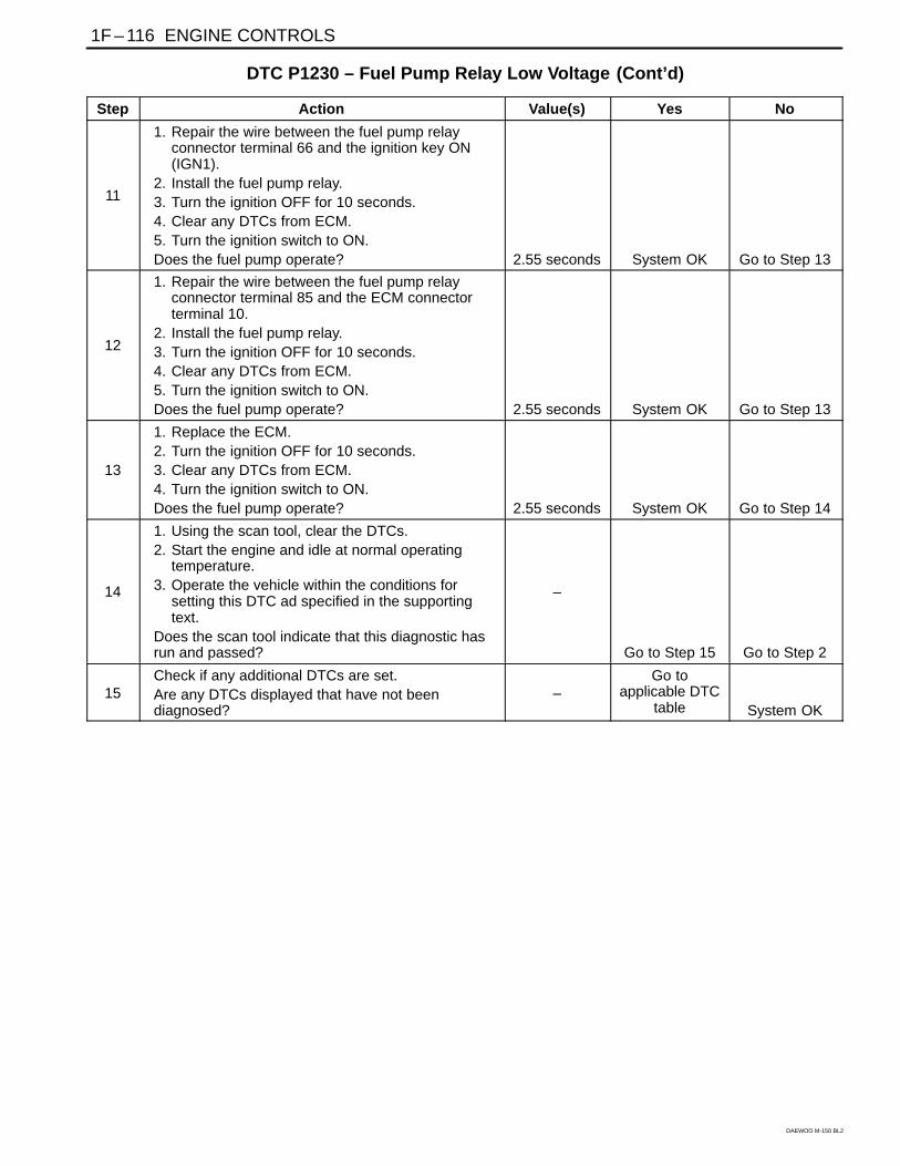
1F – 116 ENGINE CONTROLS
DAEWOO M-150 BL2
DTC P1230 – Fuel Pump Relay Low Voltage (Cont’d)
Step Action Value(s) Yes No
11
1. Repair the wire between the fuel pump relayconnector terminal 66 and the ignition key ON(IGN1).
2. Install the fuel pump relay.3. Turn the ignition OFF for 10 seconds.4. Clear any DTCs from ECM.5. Turn the ignition switch to ON.Does the fuel pump operate? 2.55 seconds System OK Go to Step 13
12
1. Repair the wire between the fuel pump relayconnector terminal 85 and the ECM connectorterminal 10.
2. Install the fuel pump relay.3. Turn the ignition OFF for 10 seconds.4. Clear any DTCs from ECM.5. Turn the ignition switch to ON.Does the fuel pump operate? 2.55 seconds System OK Go to Step 13
13
1. Replace the ECM.2. Turn the ignition OFF for 10 seconds.3. Clear any DTCs from ECM.4. Turn the ignition switch to ON.Does the fuel pump operate? 2.55 seconds System OK Go to Step 14
14
1. Using the scan tool, clear the DTCs.2. Start the engine and idle at normal operating
temperature.3. Operate the vehicle within the conditions for
setting this DTC ad specified in the supportingtext.
Does the scan tool indicate that this diagnostic hasrun and passed?
–
Go to Step 15 Go to Step 2
15Check if any additional DTCs are set.Are any DTCs displayed that have not beendiagnosed?
–Go to
applicable DTCtable System OK

ENGINE CONTROLS 1F – 117
DAEWOO M-150 BL2
BLANK
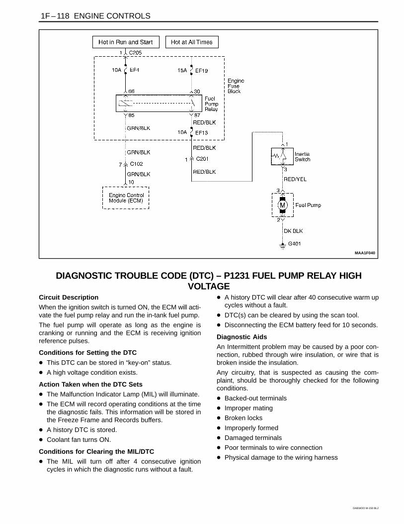
1F – 118 ENGINE CONTROLS
DAEWOO M-150 BL2
MAA1F040
DIAGNOSTIC TROUBLE CODE (DTC) – P1231 FUEL PUMP RELAY HIGHVOLTAGE
Circuit Description
When the ignition switch is turned ON, the ECM will acti-vate the fuel pump relay and run the in-tank fuel pump.
The fuel pump will operate as long as the engine iscranking or running and the ECM is receiving ignitionreference pulses.
Conditions for Setting the DTC
This DTC can be stored in “key-on” status.
A high voltage condition exists.
Action Taken when the DTC Sets
The Malfunction Indicator Lamp (MIL) will illuminate.
The ECM will record operating conditions at the timethe diagnostic fails. This information will be stored inthe Freeze Frame and Records buffers.
A history DTC is stored.
Coolant fan turns ON.
Conditions for Clearing the MIL/DTC
The MIL will turn off after 4 consecutive ignitioncycles in which the diagnostic runs without a fault.
A history DTC will clear after 40 consecutive warm upcycles without a fault.
DTC(s) can be cleared by using the scan tool.
Disconnecting the ECM battery feed for 10 seconds.
Diagnostic Aids
An Intermittent problem may be caused by a poor con-nection, rubbed through wire insulation, or wire that isbroken inside the insulation.
Any circuitry, that is suspected as causing the com-plaint, should be thoroughly checked for the followingconditions.
Backed-out terminals
Improper mating
Broken locks
Improperly formed
Damaged terminals
Poor terminals to wire connection
Physical damage to the wiring harness
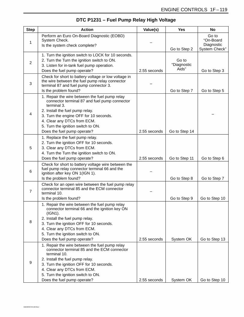
ENGINE CONTROLS 1F – 119
DAEWOO M-150 BL2
DTC P1231 – Fuel Pump Relay High Voltage
Step Action Value(s) Yes No
1
Perform an Euro On-Board Diagnostic (EOBD)System Check.Is the system check complete?
–
Go to Step 2
Go to“On-BoardDiagnostic
System Check”
2
1. Turn the ignition switch to LOCK for 10 seconds.2. Turn the Turn the ignition switch to ON.3. Listen for in-tank fuel pump operation.Does the fuel pump operate? 2.55 seconds
Go to“Diagnostic
Aids” Go to Step 3
3
Check for short to battery voltage or low voltage inthe wire between the fuel pump relay connectorterminal 87 and fuel pump connector 3.Is the problem found?
–
Go to Step 7 Go to Step 5
4
1. Repair the wire between the fuel pump relayconnector terminal 87 and fuel pump connectorterminal 3.
2. Install the fuel pump relay.3. Turn the engine OFF for 10 seconds.4. Clear any DTCs from ECM.5. Turn the ignition switch to ON.Does the fuel pump operate? 2.55 seconds Go to Step 14
–
5
1. Replace the fuel pump relay.2. Turn the ignition OFF for 10 seconds.3. Clear any DTCs from ECM.4. Turn the Turn the ignition switch to ON.Does the fuel pump operate? 2.55 seconds Go to Step 11 Go to Step 6
6
Check for short to battery voltage wire between thefuel pump relay connector terminal 66 and theignition after key ON 1(IGN 1).Is the problem found?
–
Go to Step 8 Go to Step 7
7
Check for an open wire between the fuel pump relayconnector terminal 85 and the ECM connectorterminal 10.Is the problem found?
–
Go to Step 9 Go to Step 10
8
1. Repair the wire between the fuel pump relayconnector terminal 66 and the ignition key ON(IGN1).
2. Install the fuel pump relay.3. Turn the ignition OFF for 10 seconds.4. Clear any DTCs from ECM.5. Turn the ignition switch to ON.Does the fuel pump operate? 2.55 seconds System OK Go to Step 13
9
1. Repair the wire between the fuel pump relayconnector terminal 85 and the ECM connectorterminal 10.
2. Install the fuel pump relay.3. Turn the ignition OFF for 10 seconds.4. Clear any DTCs from ECM.5. Turn the ignition switch to ON.Does the fuel pump operate? 2.55 seconds System OK Go to Step 10

1F – 120 ENGINE CONTROLS
DAEWOO M-150 BL2
DTC P1231 – Fuel Pump Relay High Voltage (Cont’d)
Step Action Value(s) Yes No
10
1. Replace the ECM.2. Turn the ignition OFF for 10 seconds.3. Clear any DTCs from ECM.4. Turn the ignition switch to ON.Does the fuel pump operate? 2.55 seconds System OK Go to Step 11
11
1. Using the scan tool, clear the DTCs.2. Start the engine and idle at normal operating
temperature.3. Operate the vehicle within the conditions for
setting this DTC ad specified in the supportingtext.
Does the scan tool indicate that this diagnostic hasrun and passed?
–
Go to Step 12 Go to Step 2
12Check if any additional DTCs are set.Are any DTCs displayed that have not beendiagnosed?
–Go to
applicable DTCtable System OK

ENGINE CONTROLS 1F – 121
DAEWOO M-150 BL2
BLANK
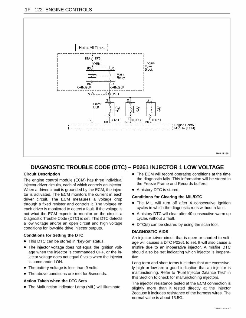
1F – 122 ENGINE CONTROLS
DAEWOO M-150 BL2
MAA1F150
DIAGNOSTIC TROUBLE CODE (DTC) – P0261 INJECTOR 1 LOW VOLTAGECircuit Description
The engine control module (ECM) has three individualinjector driver circuits, each of which controls an injector.When a driver circuit is grounded by the ECM, the injec-tor is activated. The ECM monitors the current in eachdriver circuit. The ECM measures a voltage dropthrough a fixed resistor and controls it. The voltage oneach driver is monitored to detect a fault. If the voltage isnot what the ECM expects to monitor on the circuit, aDiagnostic Trouble Code (DTC) is set. This DTC detectsa low voltage and/or an open circuit and high voltageconditions for low-side drive injector outputs.
Conditions for Setting the DTC
This DTC can be stored in “key-on” status.
The injector voltage does not equal the ignition volt-age when the injector is commanded OFF, or the in-jector voltage does not equal 0 volts when the injectoris commanded ON.
The battery voltage is less than 9 volts.
The above conditions are met for 5seconds.
Action Taken when the DTC Sets
The Malfunction Indicator Lamp (MIL) will illuminate.
The ECM will record operating conditions at the timethe diagnostic fails. This information will be stored inthe Freeze Frame and Records buffers.
A history DTC is stored.
Conditions for Clearing the MIL/DTC
The MIL will turn off after 4 consecutive ignitioncycles in which the diagnostic runs without a fault.
A history DTC will clear after 40 consecutive warm upcycles without a fault.
DTC(s) can be cleared by using the scan tool.
DIAGNOSTIC AIDS
An injector 4river circuit that is open or shorted to volt-age will causes a DTC P0261 to set. It will also cause amisfire due to an inoperative injector. A misfire DTCshould also be set indicating which injector is inopera-tive.
Long-term and short-terms fuel trims that are excessive-ly high or low are a good indication that an injector ismalfunctioning. Refer to “Fuel Injector 2alance Test” inthis Section to check for malfunctioning injectors.
The injector resistance tested at the ECM connection isslightly more than it tested directly at the injector2ecause it includes resistance of the harness wires. Thenormal value is about 13.5Ω.

ENGINE CONTROLS 1F – 123
DAEWOO M-150 BL2
DTC P0261 – Injector 1 Low Voltage
Step Action Value(s) Yes No
1
Perform an Euro On-Board Diagnostic (EOBD)System Check.Is the system check complete?
–
Go to Step 2
Go to“On-BoardDiagnostic
System Check”
2
With the engine start?
–
Go to Step 3
Go to“Engine Crank
but will notRun”
3
1. Install a scan tool and clear the DiagnosticTrouble Codes (DTCs).
2. Idle the engine for one minuet.Does DTC P0261 reset?
–
Go to Step 5 Go to Step 4
4
1. Review the Freeze Frame data with the ignitionON and the engine OFF and note theparameters.
2. Operate the vehicle within the Freeze Frameconditions as notes.
Does DTC P0261 reset?
–
Go to Step 5
Go to“Diagnostic
Aids”
5
1. Turn the ignition switch to LOCK.2. Check for short to ground in the wire between the
injector 1 connector terminal 1 and ECMconnector terminal 90.
Is the problem found?
–
Go to Step 7 Go to Step 6
6
1. Turn the ignition switch to LOCK.2. Check for short to ground in the wire between the
injector 1 connector terminal 2 and batterypositive.
Is the problem found?
–
Go to Step 7 Go to Step 8
7
1. Repair the wire or the connector terminal asneeded.
2. Clear any DTCs from ECM.3. Perform the Diagnostic System Check.Is the repair complete?
–
System OK
–
8
1. Replace the injector valve.2. Clear any DTCs from ECM.3. Perform the Diagnostic System Check.Is the repair complete?
–
Go to Step 9 System OK
9
1. Turn the ignition switch to LOCK.2. Replace the ECM.3. Perform the Diagnostic System Check.Does DTC P0261 reset?
–
Go to Step 10
–
10Check if any additional DTCs are set.Are any DTCs displaced that have not beendiagnosed?
–Go to
applicable DTCtable System OK

1F – 124 ENGINE CONTROLS
DAEWOO M-150 BL2
MAA1F150
DIAGNOSTIC TROUBLE CODE (DTC) – P0262 INJECTOR 1 HIGH VOLTAGECircuit Description
The engine control module (ECM) has three individualinjector driver circuits, each of which controls an injector.When a driver circuit is grounded by the ECM, the injec-tor is activated. The ECM monitors the current in eachdriver circuit. The ECM measures a voltage dropthrough a fixed resistor and controls it. The voltage oneach driver is monitored to detect a fault. If the voltage isnot what the ECM expects to monitor on the circuit, aDiagnostic Trouble Code (DTC) is set. This DTC detectsa low voltage and/or an open circuit and high voltageconditions for low-side drive injector outputs.
Conditions for Setting the DTC
This DTC can be stored in “key-on” status.
The injector voltage does not equal the ignition volt-age when the injector is commanded OFF, or the in-jector voltage does not equal 0 volts when the injectoris commanded ON.
The battery voltage is more than 16 volts.
The above conditions are met for 5seconds.
Action Taken when the DTC Sets
The Malfunction Indicator Lamp (MIL) will illuminate.
The ECM will record operating conditions at the timethe diagnostic fails. This information will be stored inthe Freeze Frame and Records buffers.
A history DTC is stored.
Conditions for Clearing the MIL/DTC
The MIL will turn off after 4 consecutive ignitioncycles in which the diagnostic runs without a fault.
A history DTC will clear after 40 consecutive warm upcycles without a fault.
DTC(s) can be cleared by using the scan tool.
DIAGNOSTIC AIDS
An injector 4river circuit that is open or shorted to volt-age will causes a DTC P0262 to set. It will also cause amisfire due to an inoperative injector. A misfire DTCshould also be set indicating which injector is inopera-tive.
Long-term and short-terms fuel trims that are excessive-ly high or low are a good indication that an injector ismalfunctioning. Refer to “Fuel Injector 2alance Test” inthis Section to check for malfunctioning injectors.
The injector resistance tested at the ECM connection isslightly more than it tested directly at the injector2ecause it includes resistance of the harness wires. Thenormal value is about 13.5Ω.

ENGINE CONTROLS 1F – 125
DAEWOO M-150 BL2
DTC P0262 – Injector 1 High Voltage
Step Action Value(s) Yes No
1
Perform an Euro On-Board Diagnostic (EOBD)System Check.Is the system check complete?
–
Go to Step 2
Go to“On-BoardDiagnostic
System Check”
2
With the engine start?
–
Go to Step 3
Go to“Engine Crank
but will notRun”
3
1. Install a scan tool and clear the DiagnosticTrouble Codes (DTCs).
2. Idle the engine for one minuet.Does DTC P0262 reset?
–
Go to Step 5 Go to Step 4
4
1. Review the Freeze Frame data with the ignitionON and the engine OFF and note theparameters.
2. Operate the vehicle within the Freeze Frameconditions as notes
Does DTC P0262 reset?
–
Go to Step 5
Go to“Diagnostic
Aids”
5
1. Turn the ignition switch to Lock.2. Check for an open or short to battery voltage in
the wire between the injector 1 connector terminal1 and ECM connector terminal 90.
Is the problem found?
–
Go to Step 7 Go to Step 6
6
1. Turn the ignition switch to Lock.2. Check for short to battery voltage in the wire
between the injector 1 connector terminal 2 andbattery positive.
Is the problem found?
–
Go to Step 7 Go to Step 8
7
1. Repair the wire or the connector terminal asneeded.
2. Clear any DTCs from ECM.3. Perform the Diagnostic System Check.Is the repair complete?
–
System OK
–
8
1. Replace the injector valve2. Clear any DTCs from ECM.3. Perform the Diagnostic System Check.Does DTC P0262 reset?
–
Go to Step 9 System OK
9
1. Turn the ignition switch to LOCK.2. Replace the ECM.3. Perform the Diagnostic System Check.Is the repair complete?
–
Go to Step 10
–
10Check if any additional DTCs are set.Are any DTCs displaced that have not beendiagnosed?
–Go to
applicable DTCtable System OK

1F – 126 ENGINE CONTROLS
DAEWOO M-150 BL2
MAA1F150
DIAGNOSTIC TROUBLE CODE (DTC) – P0264 INJECTOR 2 LOW VOLTAGECircuit Description
The engine control module (ECM) has three individualinjector driver circuits, each of which controls an injector.When a driver circuit is grounded by the ECM, the injec-tor is activated. The ECM monitors the current in eachdriver circuit. The ECM measures a voltage dropthrough a fixed resistor and controls it. The voltage oneach driver is monitored to detect a fault. If the voltage isnot what the ECM expects to monitor on the circuit, aDiagnostic Trouble Code (DTC) is set. This DTC detectsa low voltage and/or an open circuit and high voltageconditions for low-side drive injector outputs.
Conditions for Setting the DTC
This DTC can be stored in “key-on” status.
The injector voltage does not equal the ignition volt-age when the injector is commanded OFF, or the in-jector voltage does not equal 0 volts when the injectoris commanded ON.
The battery voltage is less than 9 volts.
The above conditions are met for 5 seconds.
Action Taken when the DTC Sets
The Malfunction Indicator Lamp (MIL) will illuminate.
The ECM will record operating conditions at the timethe diagnostic fails. This information will be stored inthe Freeze Frame and Records buffers.
A history DTC is stored.
Conditions for Clearing the MIL/DTC
The MIL will turn off after 4 consecutive ignitioncycles in which the diagnostic runs without a fault.
A history DTC will clear after 40 consecutive warm upcycles without a fault.
DTC(s) can be cleared by using the scan tool.
DIAGNOSTIC AIDS
An injector 4river circuit that is open or shorted to volt-age will causes a DTC P0264 to set. It will also cause amisfire due to an inoperative injector. A misfire DTCshould also be set indicating which injector is inopera-tive.
Long-term and short-terms fuel trims that are excessive-ly high or low are a good indication that an injector ismalfunctioning. Refer to “Fuel Injector 2alance Test” inthis Section to check for malfunctioning injectors.
The injector resistance tested at the ECM connection isslightly more than it tested directly at the injector2ecause it includes resistance of the harness wires. Thenormal value is about 13.5Ω.

ENGINE CONTROLS 1F – 127
DAEWOO M-150 BL2
DTC P0264 – Injector 2 Low Voltage
Step Action Value(s) Yes No
1
Perform an Euro On-Board Diagnostic (EOBD)System Check.Is the system check complete?
–
Go to Step 2
Go to“On-BoardDiagnostic
System Check”
2
With the engine start?
–
Go to Step 3
Go to“Engine Crank
but will notRun”
3
1. Install a scan tool and clear the DiagnosticTrouble Codes (DTCs).
2. Idle the engine for one minuet.Does DTC P2064 reset?
–
Go to Step 5 Go to Step 4
4
1. Review the Freeze Frame data with the ignitionON and the engine OFF and note theparameters.
2. Operate the vehicle within the Freeze Frameconditions as notes
Does DTC P0264 reset?
–
Go to Step 5
Go to“Diagnostic
Aids”
5
1. Turn the ignition switch to LOCK.2. Check for short to ground in the wire between the
injector 2 connector terminal 1 and ECMconnector terminal 58.
Is the problem found?
–
Go to Step 7 Go to Step 6
6
1. Turn the ignition switch to LOCK.2. Check for short to ground in the wire between the
injector 2 connector terminal 2 and batterypositive.
Is the problem found?
–
Go to Step 7 Go to Step 8
7
1. Repair the wire or the connector terminal asneeded.
2. Clear any DTCs from ECM.3. Perform the Diagnostic System Check.Is the repair complete?
–
System OK
–
8
1. Replace the injector valve.2. Clear any DTCs from ECM.3. Perform the Diagnostic System Check.Does DTC P0264 reset?
–
Go to Step 9 System OK
9
1. Turn the ignition switch to LOCK.2. Replace the ECM.3. Perform the Diagnostic System Check.Is the repair complete?
–
Go to Step 10
–
10Check if any additional DTCs are set.Are any DTCs displaced that have not beendiagnosed?
–Go to
applicable DTCtable System OK

1F – 128 ENGINE CONTROLS
DAEWOO M-150 BL2
MAA1F150
DIAGNOSTIC TROUBLE CODE (DTC) – P0265 INJECTOR 2 HIGH VOLTAGECircuit Description
The engine control module (ECM) has three individualinjector driver circuits, each of which controls an injector.When a driver circuit is grounded by the ECM, the injec-tor is activated. The ECM monitors the current in eachdriver circuit. The ECM measures a voltage dropthrough a fixed resistor and controls it. The voltage oneach driver is monitored to detect a fault. If the voltage isnot what the ECM expects to monitor on the circuit, aDiagnostic Trouble Code (DTC) is set. This DTC detectsa low voltage and/or an open circuit and high voltageconditions for low-side drive injector outputs.
Conditions for Setting the DTC
This DTC can be stored in “key-on” status.
The injector voltage does not equal the ignition volt-age when the injector is commanded OFF, or the in-jector voltage does not equal 0 volts when the injectoris commanded ON.
The battery voltage is more than 16 volts.
The above conditions are met for 5 seconds.
Action Taken when the DTC Sets
The Malfunction Indicator Lamp (MIL) will illuminate.
The ECM will record operating conditions at the timethe diagnostic fails. This information will be stored inthe Freeze Frame and Records buffers.
A history DTC is stored.
Conditions for Clearing the MIL/DTC
The MIL will turn off after 4 consecutive ignitioncycles in which the diagnostic runs without a fault.
A history DTC will clear after 40 consecutive warm upcycles without a fault.
DTC(s) can be cleared by using the scan tool.
DIAGNOSTIC AIDS
An injector 4river circuit that is open or shorted to volt-age will causes a DTC P0265 to set. It will also cause amisfire due to an inoperative injector. A misfire DTCshould also be set indicating which injector is inopera-tive.
Long-term and short-terms fuel trims that are excessive-ly high or low are a good indication that an injector ismalfunctioning. Refer to “Fuel Injector 2alance Test” inthis Section to check for malfunctioning injectors.
The injector resistance tested at the ECM connection isslightly more than it tested directly at the injector be-cause it includes resistance of the harness wires. Thenormal value is about 13.5Ω.
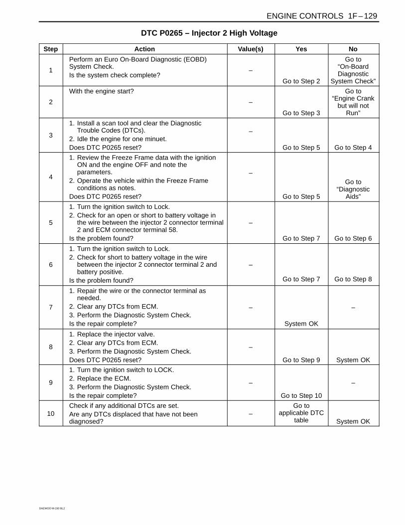
ENGINE CONTROLS 1F – 129
DAEWOO M-150 BL2
DTC P0265 – Injector 2 High Voltage
Step Action Value(s) Yes No
1
Perform an Euro On-Board Diagnostic (EOBD)System Check.Is the system check complete?
–
Go to Step 2
Go to“On-BoardDiagnostic
System Check”
2
With the engine start?
–
Go to Step 3
Go to“Engine Crank
but will notRun”
3
1. Install a scan tool and clear the DiagnosticTrouble Codes (DTCs).
2. Idle the engine for one minuet.Does DTC P0265 reset?
–
Go to Step 5 Go to Step 4
4
1. Review the Freeze Frame data with the ignitionON and the engine OFF and note theparameters.
2. Operate the vehicle within the Freeze Frameconditions as notes.
Does DTC P0265 reset?
–
Go to Step 5
Go to“Diagnostic
Aids”
5
1. Turn the ignition switch to Lock.2. Check for an open or short to battery voltage in
the wire between the injector 2 connector terminal2 and ECM connector terminal 58.
Is the problem found?
–
Go to Step 7 Go to Step 6
6
1. Turn the ignition switch to Lock.2. Check for short to battery voltage in the wire
between the injector 2 connector terminal 2 andbattery positive.
Is the problem found?
–
Go to Step 7 Go to Step 8
7
1. Repair the wire or the connector terminal asneeded.
2. Clear any DTCs from ECM.3. Perform the Diagnostic System Check.Is the repair complete?
–
System OK
–
8
1. Replace the injector valve.2. Clear any DTCs from ECM.3. Perform the Diagnostic System Check.Does DTC P0265 reset?
–
Go to Step 9 System OK
9
1. Turn the ignition switch to LOCK.2. Replace the ECM.3. Perform the Diagnostic System Check.Is the repair complete?
–
Go to Step 10
–
10Check if any additional DTCs are set.Are any DTCs displaced that have not beendiagnosed?
–Go to
applicable DTCtable System OK

1F – 130 ENGINE CONTROLS
DAEWOO M-150 BL2
MAA1F150
DIAGNOSTIC TROUBLE CODE (DTC) – P0267 INJECTOR 3 LOW VOLTAGECircuit Description
The engine control module (ECM) has three individualinjector driver circuits, each of which controls an injector.When a driver circuit is grounded by the ECM, the injec-tor is activated. The ECM monitors the current in eachdriver circuit. The ECM measures a voltage dropthrough a fixed resistor and controls it. The voltage oneach driver is monitored to detect a fault. If the voltage isnot what the ECM expects to monitor on the circuit, aDiagnostic Trouble Code (DTC) is set. This DTC detectsa low voltage and/or an open circuit and high voltageconditions for low-side drive injector outputs.
Conditions for Setting the DTC
This DTC can be stored in “key-on” status.
The injector voltage does not equal the ignition volt-age when the injector is commanded OFF, or the in-jector voltage does not equal 0 volts when the injectoris commanded ON.
The battery voltage is less than 9 volts.
The above conditions are met for 5 seconds.
Action Taken when the DTC Sets
The Malfunction Indicator Lamp (MIL) will illuminate.
The ECM will record operating conditions at the timethe diagnostic fails. This information will be stored inthe Freeze Frame and Records buffers.
A history DTC is stored.
Conditions for Clearing the MIL/DTC
The MIL will turn off after 4 consecutive ignitioncycles in which the diagnostic runs without a fault.
A history DTC will clear after 40 consecutive warm upcycles without a fault.
DTC(s) can be cleared by using the scan tool.
DIAGNOSTIC AIDS
An injector 4river circuit that is open or shorted to volt-age will causes a DTC P0267 to set. It will also cause amisfire due to an inoperative injector. A misfire DTCshould also be set indicating which injector is inopera-tive.
Long-term and short-terms fuel trims that are excessive-ly high or low are a good indication that an injector ismalfunctioning. Refer to “Fuel Injector 3alance Test” inthis Section to check for malfunctioning injectors.
The injector resistance tested at the ECM connection isslightly more than it tested directly at the injector be-cause it includes resistance of the harness wires. Thenormal value is about 13.5Ω.

ENGINE CONTROLS 1F – 131
DAEWOO M-150 BL2
DTC P0267 – Injector 3 Low Voltage
Step Action Value(s) Yes No
1
Perform an Euro On-Board Diagnostic (EOBD)System Check.Is the system check complete?
–
Go to Step 2
Go to“On-BoardDiagnostic
System Check”
2
With the engine start?
–
Go to Step 3
Go to“Engine Crank
but will notRun”
3
1. Install a scan tool and clear the DiagnosticTrouble Codes (DTCs).
2. Idle the engine for one minuet.Does DTC P0267 reset?
–
Go to Step 5 Go to Step 4
4
1. Review the Freeze Frame data with the ignitionON and the engine OFF and note theparameters.
2. Operate the vehicle within the Freeze Frameconditions as notes.
Does DTC P0267 reset?
–
Go to Step 5
Go to“Diagnostic
Aids”
5
1. Turn the ignition switch to LOCK.2. Check for short to ground in the wire between the
injector 3 connector terminal 1 and ECMconnector terminal 89.
Is the problem found?
–
Go to Step 7 Go to Step 6
6
1. Turn the ignition switch to LOCK.2. Check for short to ground in the wire between the
injector 3 connector terminal 2 and batterypositive.
Is the problem found?
–
Go to Step 7 Go to Step 8
7
1. Repair the wire or the connector terminal asneeded.
2. Clear any DTCs from ECM.3. Perform the Diagnostic System Check.Is the repair complete?
–
System OK
–
8
1. Replace the injector valve.2. Clear any DTCs from ECM.3. Perform the Diagnostic System Check.Does DTC P0267 reset?
–
Go to Step 9 System OK
9
1. Turn the ignition switch to LOCK.2. Replace the ECM.3. Perform the Diagnostic System Check.Is the repair complete?
–
Go to Step 10
–
10Check if any additional DTCs are set.Are any DTCs displaced that have not beendiagnosed?
–Go to
applicable DTCtable System OK

1F – 132 ENGINE CONTROLS
DAEWOO M-150 BL2
MAA1F150
DIAGNOSTIC TROUBLE CODE (DTC) – P0268 INJECTOR 3 HIGH VOLTAGECircuit Description
The engine control module (ECM) has three individualinjector driver circuits, each of which controls an injector.When a driver circuit is grounded by the ECM, the injec-tor is activated. The ECM monitors the current in eachdriver circuit. The ECM measures a voltage dropthrough a fixed resistor and controls it. The voltage oneach driver is monitored to detect a fault. If the voltage isnot what the ECM expects to monitor on the circuit, aDiagnostic Trouble Code (DTC) is set. This DTC detectsa low voltage and/or an open circuit and high voltageconditions for low-side drive injector outputs.
Conditions for Setting the DTC
This DTC can be stored in “key-on” status.
The injector voltage does not equal the ignition volt-age when the injector is commanded OFF, or the in-jector voltage does not equal 0 volts when the injectoris commanded ON.
The battery voltage is more than 16 volts.
The above conditions are met for 5 seconds.
Action Taken when the DTC Sets
The Malfunction Indicator Lamp (MIL) will illuminate.
The ECM will record operating conditions at the timethe diagnostic fails. This information will be stored inthe Freeze Frame and Records buffers.
A history DTC is stored.
Conditions for Clearing the MIL/DTC
The MIL will turn off after consecutive ignition cyclesin which the diagnostic runs without a fault.
A history DTC will clear after 40 consecutive warm upcycles without a fault.
DTC(s) can be cleared by using the scan tool.
Disconnecting the ECM battery feed for 10 seconds.
DIAGNOSTIC AIDS
An injector 4river circuit that is open or shorted to volt-age will causes a DTC P0268 to set. It will also cause amisfire due to an inoperative injector. A misfire DTCshould also be set indicating which injector is inopera-tive.
Long-term and short-terms fuel trims that are excessive-ly high or low are a good indication that an injector ismalfunctioning. Refer to “Fuel Injector 3alance Test” inthis Section to check for malfunctioning injectors.

ENGINE CONTROLS 1F – 133
DAEWOO M-150 BL2
The injector resistance tested at the ECM connection isslightly more than it tested directly at the injector be-
cause it includes resistance of the harness wires. Thenormal value is about 13.5Ω.
DTC P0268 – Injector 3 High Voltage
Step Action Value(s) Yes No
1
Perform an Euro On-Board Diagnostic (EOBD)System Check.Is the system check complete?
–
Go to Step 2
Go to“On-BoardDiagnostic
System Check”
2
With the engine start?
–
Go to Step 3
Go to“Engine Crank
but will notRun”
3
1. Install a scan tool and clear the DiagnosticTrouble Codes (DTCs).
2. Idle the engine for one minuet.Does DTC P0268 reset?
–
Go to Step 5 Go to Step 4
4
1. Review the Freeze Frame data with the ignitionON and the engine OFF and note theparameters.
2. Operate the vehicle within the Freeze Frameconditions as notes.
Does DTC P0268 reset?
–
Go to Step 5
Go to“Diagnostic
Aids”
5
1. Turn the ignition switch to Lock.2. Check for an open or short to battery voltage in
the wire between the injector 3 connector terminal1 and ECM connector terminal 89.
Is the problem found?
–
Go to Step 7 Go to Step 6
6
1. Turn the ignition switch to Lock.2. Check for short to battery voltage in the wire
between the injector 3 connector terminal 2 andbattery positive.
Is the problem found?
–
Go to Step 7 Go to Step 8
7
1. Repair the wire or the connector terminal asneeded.
2. Clear any DTCs from ECM.3. Perform the Diagnostic System Check.Is the repair complete?
–
System OK
–
8
1. Replace the injector valve.2. Clear any DTCs from ECM.3. Perform the Diagnostic System Check.Does DTC P0268 reset?
–
Go to Step 9 System OK
9
1. Turn the ignition switch to LOCK.2. Replace the ECM.3. Perform the Diagnostic System Check.Is the repair complete?
–
Go to Step 10
–
10Check if any additional DTCs are set.Are any DTCs displaced that have not beendiagnosed?
–Go to
applicable DTCtable System OK

1F – 134 ENGINE CONTROLS
DAEWOO M-150 BL2
MAA1F160

ENGINE CONTROLS 1F – 135
DAEWOO M-150 BL2
DIAGNOSTIC TROUBLE CODE (DTC) – P0300 MULTIPLE CYLINDER MISFIRESystem Description
The Engine Control Module (ECM) monitors the crank-shaft and camshaft positions to detect if the engine ismisfiring. The ECM looks for a quick drop in crankshaftspeed. This test is executed in blocks of 100 engine rev-olution tests. It may take between one to several tests tostore a Diagnostic Trouble Code (DTC) and illuminatethe Malfunction Indicator Lamp (MIL). Under light misfireconditions, it may also take more than one trip to set aDTC. Severe misfire will flash the MIL, indicating thatcatalyst damage is possible.
Conditions for Setting the DTC
Emission threshold is 3.0% for manual transaxle.
20 engine cycles have occurred since cranking hasstarted.
A/C compressor clutch has not just engaged or disen-gaged.
Engine load and engine speed are in a detectable re-gion and are at or above zero torque.
Camshaft Position (CMP) sensor is in synchroniza-tion.
Electric Exhaust Gas Recirculation (EEGR) flowdiagnostic is not in progress.
Fuel level is greater than or equal to 20% of ratedtank capacity.
Decel Fuel Cutoff (DFCO) not active.
Fuel is not shutoff from high engine speed of 6500rpm for manual transaxle vehicle.
Fuel is not shutoff at 255 km/h (158 mph).
Throttle position change is less than 3% per 125 ms.
Vehicle has not encountered an abusive enginespeed of 7000 rpm.
Crankshaft speed patters are normal.
Throttle position is less than 4% when vehicle speedis greater than 10 km/h (6 mph).
Engine speed is between 800 and 4500 rpm.
Vehicle voltage is between 11 and 16 volts.
Engine Coolant Temperature (ECT) is between –7°C(20°F) and 120°C (248°F).
The engine speed is less than or equal to 1800 rpm orthe crank angle sensing error has not been learned.
There is the correct ratio between Crankshaft Posi-tion (CKP) sensor pulses and CMP sensor pulses.
DTCs P0106, P0107, P0108, P0117, P0118, P0122,P0123, P0320, P0337, P0341, P0342 and P0502 arenot set.
Action Taken when the DTC Sets
The malfunction Indicator Lamp (MIL) will blinking.
The ECM will record operating conditions at the timethe diagnostic fails. The information will be stored inthe Freeze Frame and failure records buffers.
A history DTC is stored.
Conditions for Clearing the MIL/DTC
A history DTC will clear after 40 consecutive warm upcycles without a fault.
DTC(s) can be cleared by using the scan tool.
Diagnostic Aids
An intermittent can also be the result of a defective re-luctor wheel. Remove the CKP sensor and inspect thereluctor wheel through the sensor mount hole. Check forporosity and the condition of wheel. If the DTC is inter-mittent refer to “Symptoms Diagnosis” in this section.
DTC P0300 – Multiple Cylinder Misfire
Step Action Value(s) Yes No
1
Perform an Euro On-Board Diagnostic (EOBD)System Check.Was the check performed?
–
Go to Step 2
Go to“On-BoardDiagnostic
System Check”
2
1. Install a scan tool to the Data Link Connector(DLC).
2. Turn the ignition ON, with the engine OFF.3. Request Diagnostic Trouble Codes (DTCs)Are DTCs P0201, P0202, P0203, P0204 set?
– Go toApplicable DTC
table Go to Step 3
3Perform a visual/physical inspection.Make any repairs that are necessary.Is the repair complete?
–
Go to Step 27 Go to Step 4
4Start the engine and allow it to idle.Are any Misfire Current counters incrementing?
–Go to Step 5 Go to Step 6
5Are all counters equal (within a percentage of eachother)? –
Go to Step 7 Go to Step 11

1F – 136 ENGINE CONTROLS
DAEWOO M-150 BL2
DTC P0300 – Multiple Cylinder Misfire (Cont’d)
Step Action Value(s) Yes No
6
1. Turn the ignition ON, with the engine OFF.2. Review the Freeze Frame data, and note the
parameters.3. Operate the vehicle within the Freeze Frame
conditions and conditions for setting this DTC asnoted.
Are any Misfire Current counters incrementing?
–
Go to Step 5
Go to“Diagnostic
Aids”
7
1. Turn the engine OFF.2. Install a fuel pressure gauge to the fuel rail.3. Observe the fuel pressure with the engine
running.Is the fuel pressure within the specified value?
284–325 kPa(41–47 psi) Go to Step 8
Go to“Fuel System
Diagnosis”
8Check the fuel for contamination.Is the fuel OK?
–Go to Step 9 Go to Step 10
9Check for a basic engine problem and repair asnecessary.Is the repair complete?
–Go to Step 27
–
10Replace the contaminated fuel.Is the repair complete?
–Go to Step 27
–
11
1. Turn the engine OFF.2. Disconnect the fuel injector harness connector.3. Install a spark tester on cylinder #1 spark plug
cable.4. Crank the engine and check for spark.5. Repeat the above procedure on cylinders #2, #3.Is a spark observed on all four spark plug cables?
–
Go to Step 12 Go to Step 20
12Replace any malfunctioning spark plugs ifnecessary.Is the repair complete?
–Go to Step 27 Go to Step 13
13
1. Turn the engine OFF.2. Disconnect the fuel injector connectors from the
injectors.3. Install an injector test light on the injector harness
connector for the cylinders that had misfired.4. Crank the engine and note the test light.Does the injector test light blink?
–
Go to Step 14 Go to Step 15
14Perform the Fuel Injector Balance Test.Are the fuel injectors OK?
–Go to Step 9 Go to Step 16
15
1. Disconnect the injector test light.2. With a test light connected to ground, probe the
ignition feed terminal 1 of the injector harnessconnector for each cylinder that had misfire.
3. Crank the engine.Does the test light illuminate?
–
Go to Step 17 Go to Step 19
16Replace any malfunctioning fuel injectors.Is the repair complete?
–Go to Step 27
–
17
Check the affected fuel injector driver circuit atterminals 90, 58 and 89 for an open, short, or shortto voltage.Is a problem found?
–
Go to Step 18 Go to Step 24
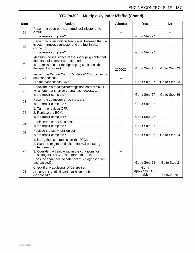
ENGINE CONTROLS 1F – 137
DAEWOO M-150 BL2
DTC P0300 – Multiple Cylinder Misfire (Cont’d)
Step Action Value(s) Yes No
18Repair the open or the shorted fuel injector drivercircuit.Is the repair complete?
–Go to Step 27
–
19
Repair the open ignition feed circuit between the fuelinjector harness connector and the fuel injectorconnector.Is the repair complete?
–
Go to Step 27
–
20
Measure the resistance of the spark plug cable thatthe spark plug tester did not spark.Is the resistance of the spark plug cable less thanthe specified value? 30000Ω Go to Step 21 Go to Step 25
21Inspect the Engine Control Module (ECM) connectorand connections.Are the connections OK?
–Go to Step 22 Go to Step 23
22Check the affected cylinders ignition control circuitfor an open or short and repair as necessary.Is the repair complete?
–Go to Step 27 Go to Step 26
23Repair the connector or connections.Is the repair complete?
–Go to Step 27
–
241. Turn the ignition OFF.2. Replace the ECM.Is the repair complete?
–Go to Step 27
–
25Replace the spark plug cable.Is the repair complete?
–Go to Step 27
–
26Replace the faulty ignition coil.Is the repair complete?
–Go to Step 27 Go to Step 24
27
1. Using the scan tool, clear the DTCs.2. Start the engine and idle at normal operating
temperature.3. Operate the vehicle within the conditions for
setting this DTC as supported in the text.Does the scan tool indicate that this diagnostic ranand passed?
–
Go to Step 28 Go to Step 2
28Check if any additional DTCs are set.Are any DTCs displayed that have not beendiagnosed?
–Go to
Applicable DTCtable System OK

1F – 138 ENGINE CONTROLS
DAEWOO M-150 BL2
MAA1F160

ENGINE CONTROLS 1F – 139
DAEWOO M-150 BL2
DIAGNOSTIC TROUBLE CODE (DTC) – P0300 MULTIPLE CYLINDER MISFIRESystem Description
The Engine Control Module (ECM) monitors the crank-shaft and camshaft positions to detect if the engine ismisfiring. The ECM looks for a quick drop in crankshaftspeed. This test is executed in blocks of 100 engine rev-olution tests. It may take between one to several tests tostore a Diagnostic Trouble Code (DTC) and illuminatethe Malfunction Indicator Lamp (MIL). Under light misfireconditions, it may also take more than one trip to set aDTC. Severe misfire will flash the MIL, indicating thatcatalyst damage is possible.
Conditions for Setting the DTC
Emission threshold is 3.0% for automatic transaxleand 3.0% for manual transaxle.
20 engine cycles have occurred since cranking hasstarted.
A/C compressor clutch has not just engaged or disen-gaged.
Engine load and engine speed are in a detectable re-gion and are at or above zero torque.
Camshaft Position (CMP) sensor is in synchroniza-tion.
Electric Exhaust Gas Recirculation (EEGR) flowdiagnostic is not in progress.
Fuel level is greater than or equal to 20% of ratedtank capacity.
Decel Fuel Cutoff (DFCO) not active.
Fuel is not shutoff from high engine speed of 6500rpm for manual transaxle vehicle or 6500 rpm in driveand 6250 rpm in park for automatic transaxle ve-hicles.
Fuel is not shutoff at 255 km/h (158 mph).
An automatic transmission is not shifting.
Throttle position change is less than 3% per 125 ms.
Vehicle has not encountered an abusive enginespeed of 7000 rpm.
Crankshaft speed patters are normal.
Throttle position is less than 4% when vehicle speedis greater than 10 km/h (6 mph).
Engine speed is between 600 and 4500 rpm.
Vehicle voltage is between 11 and 16 volts.
Engine Coolant Temperature (ECT) is between –7°C(20°F) and 120°C (248°F).
The engine speed is less than or equal to 1800 rpm orthe crank angle sensing error has not been learned.
There is the correct ratio between Crankshaft Posi-tion (CKP) sensor pulses and CMP sensor pulses.
DTCs P0106, P0107, P0108, P0117, P0118, P0122,P0123, P0320, P0337, P0341, P0342 and P0502 arenot set.
Action Taken when the DTC Sets
Emission related.
“Armed” after two trip with a fail.
“Disarmed” after one trip with a pass.
MIL on if failure is detected in three consecutive trips.
Stores a History DTC on the third consecutive with afail (The DTC will be armed after the second fail).
Stores a Freeze Frame on the third consecutive tripwith a fail (if empty).
Conditions for Clearing the MIL/DTC
The MIL will turn off after four consecutive ignitioncycles in which the diagnostic runs without a fault.
A history DTC will clear after 40 consecutive warm upcycles without a fault.
DTC(s) can be cleared by using the scan tool.
Disconnecting the ECM battery feed for 10 seconds.
Diagnostic Aids
An intermittent can also be the result of a defective re-luctor wheel. Remove the CKP sensor and inspect thereluctor wheel through the sensor mount hole. Check forporosity and the condition of wheel. If the DTC is inter-mittent refer to “Symptoms Diagnosis” in this section.
DTC P0300 – Multiple Cylinder Misfire
Step Action Value(s) Yes No
1
Perform an Euro On-Board Diagnostic (EOBD)System Check.Was the check performed?
–
Go to Step 2
Go to“On-BoardDiagnostic
System Check”
2
1. Install a scan tool to the Data Link Connector(DLC).
2. Turn the ignition ON, with the engine OFF.3. Request Diagnostic Trouble Codes (DTCs)Are DTCs P0201, P0202, P0203, P0204 set?
– Go toApplicable DTC
table Go to Step 3

1F – 140 ENGINE CONTROLS
DAEWOO M-150 BL2
DTC P0300 – Multiple Cylinder Misfire (Cont’d)
Step Action Value(s) Yes No
3Perform a visual/physical inspection.Make any repairs that are necessary.Is the repair complete?
–
Go to Step 27 Go to Step 4
4Start the engine and allow it to idle.Are any Misfire Current counters incrementing?
–Go to Step 5 Go to Step 6
5Are all counters equal (within a percentage of eachother)? –
Go to Step 7 Go to Step 11
6
1. Turn the ignition ON, with the engine OFF.2. Review the Freeze Frame data, and note the
parameters.3. Operate the vehicle within the Freeze Frame
conditions and conditions for setting this DTC asnoted.
Are any Misfire Current counters incrementing?
–
Go to Step 5
Go to“Diagnostic
Aids”
7
1. Turn the engine OFF.2. Install a fuel pressure gauge to the fuel rail.3. Observe the fuel pressure with the engine
running.Is the fuel pressure within the specified value?
284–325 kPa(41–47 psi) Go to Step 8
Go to“Fuel System
Diagnosis”
8Check the fuel for contamination.Is the fuel OK?
–Go to Step 9 Go to Step 10
9Check for a basic engine problem and repair asnecessary.Is the repair complete?
–Go to Step 27
–
10Replace the contaminated fuel.Is the repair complete?
–Go to Step 27
–
11
1. Turn the engine OFF.2. Disconnect the fuel injector harness connector.3. Install a spark tester on cylinder #1 spark plug
cable.4. Crank the engine and check for spark.5. Repeat the above procedure on cylinders #2, #3.Is a spark observed on all four spark plug cables?
–
Go to Step 12 Go to Step 20
12Replace any malfunctioning spark plugs ifnecessary.Is the repair complete?
–Go to Step 27 Go to Step 13
13
1. Turn the engine OFF.2. Disconnect the fuel injector connectors from the
injectors.3. Install an injector test light on the injector harness
connector for the cylinders that had misfired.4. Crank the engine and note the test light.Does the injector test light blink?
–
Go to Step 14 Go to Step 15
14Perform the Fuel Injector Balance Test.Are the fuel injectors OK?
–Go to Step 9 Go to Step 16
15
1. Disconnect the injector test light.2. With a test light connected to ground, probe the
ignition feed terminal 1 of the injector harnessconnector for each cylinder that had misfire.
3. Crank the engine.Does the test light illuminate?
–
Go to Step 17 Go to Step 19

ENGINE CONTROLS 1F – 141
DAEWOO M-150 BL2
DTC P0300 – Multiple Cylinder Misfire (Cont’d)
Step Action Value(s) Yes No
16Replace any malfunctioning fuel injectors.Is the repair complete?
–Go to Step 27
–
17
Check the affected fuel injector driver circuit atterminals 90, 58, and 89 for an open, short, or shortto voltage.Is a problem found?
–
Go to Step 18 Go to Step 24
18Repair the open or the shorted fuel injector drivercircuit.Is the repair complete?
–Go to Step 27
–
19
Repair the open ignition feed circuit between the fuelinjector harness connector and the fuel injectorconnector.Is the repair complete?
–
Go to Step 27
–
20
Measure the resistance of the spark plug cable thatthe spark plug tester did not spark.Is the resistance of the spark plug cable less thanthe specified value? 30000Ω Go to Step 21 Go to Step 25
21Inspect the Engine Control Module (ECM) connectorand connections.Are the connections OK?
–Go to Step 22 Go to Step 23
22Check the affected cylinders ignition control circuitfor an open or short and repair as necessary.Is the repair complete?
–Go to Step 27 Go to Step 26
23Repair the connector or connections.Is the repair complete?
–Go to Step 27
–
241. Turn the ignition OFF.2. Replace the ECM.Is the repair complete?
–Go to Step 27
–
25Replace the spark plug cable.Is the repair complete?
–Go to Step 27
–
26Replace the faulty ignition coil.Is the repair complete?
–Go to Step 27 Go to Step 24
27
1. Using the scan tool, clear the DTCs.2. Start the engine and idle at normal operating
temperature.3. Operate the vehicle within the conditions for
setting this DTC as supported in the text.Does the scan tool indicate that this diagnostic ranand passed?
–
Go to Step 28 Go to Step 2
28Check if any additional DTCs are set.Are any DTCs displayed that have not beendiagnosed?
–Go to
Applicable DTCtable System OK
1F – 142 ENGINE CONTROLS
DAEWOO M-150 BL2
DIAGNOSTIC TROUBLE CODE (DTC) – P1320 CRANKSHAFT SEGMENTPERIOD SEGMENT ADAPTATION AT LIMIT
Circuit Description
The 58X reference signal is produced by the CrankshaftPosition (CKP) sensor. During one crankshaft revolu-tion, 58 crankshaft pulses will be produced. The EngineControl Module (ECM) uses the 58X reference signal tocalculate engine rpm and CKP. The ECM constantlymonitors the number of pulses on the 58X reference cir-cuit and compares them to the number of CamshaftPosition (CMP) signal pulses being received. If the ECMreceives and incorrect number of pulses on the 58X ref-erence circuit, Diagnostic Trouble Code (DTC) P0320will set.
Conditions for Setting the DTC
Engine is running.
Number of extra or missing teeth is greater than orequal to 2 per revolution.
Above condition is detected in 10 of 100 crankshaftrotations.
Action Taken When the DTC Sets
The Malfunction Indicator Lamp (MIL) will illuminate.
The ECM will record operating conditions at the timethe diagnostic fails. This information will be stored inthe Freeze Frame and Failure Records buffers.
A history DTC is stored.
Conditions for Clearing the MIL/DTC
The MIL will turn off after four consecutive ignitioncycles in which the diagnostic runs without a fault.
A history DTC will clear after 40 consecutive warm-upcycles without a fault.
DTC(s) can be cleared by using the scan tool.
Diagnostic Aids
An intermittent may be caused by a poor connection,rubbed-through wire insulation or a wire broken insidethe insulation. Check for:
Poor connection – Inspect the ECM harness and con-nectors for improper mating, broken locks, improperlyformed or damaged terminals, and poor terminal-to-wire connections.
Damaged harness – Inspect the wiring harness fordamage. If the harness appears to be OK, disconnectthe ECM, turn the ignition ON and observe a voltme-ter connected to the 58X reference circuit at the ECMharness connector while moving the connectors andthe wiring harnesses related to the ECM. A change involtage will indicate the location of the fault.
Reviewing the Failure Records vehicle mileage sincethe diagnostic test last failed may help determine howoften the condition that caused the DTC to be set oc-curs. This may assist in diagnosing the condition.

ENGINE CONTROLS 1F – 143
DAEWOO M-150 BL2
DTC P1320 – Crankshaft Segment Period Segment Adaptation At Limit
Step Action Value(s) Yes No
1
Perform an Euro On-Board Diagnostic (EOBD)System Check.Was the check performed?
–
Go to Step 2
Go to“On-BoardDiagnostic
System Check”
2
Attempt to start the engine.Does the engine start? –
Go to Step 3
Refer to“Engine
Cranks ButWill Not Run”
3
1. Turn the ignition OFF.2. Install a scan tool to the Data Link Connector
(DLC).3. Turn the ignition ON, with the engine OFF.4. Review and record Failure Records information.5. Clear the Diagnostic Trouble Codes (DTCs).6. Start the engine and idle for 1 minute.Is DTC P1320 set?
–
Go to Step 4
Go to“Diagnostic
Aids”
4
1. Remove the crankshaft.2. Check for a problem with the crahkshaft’s visual
defection and tooth.Is a problem found?
–
Go to Step 5 Go to Step 6
5Replace the crankshaft.Is the replacement complete?
–System OK
–
61. Turn the ignition OFF.2. Replace the ECM.Is the repair complete?
–Go to Step 7
–
7
1. Using the scan tool, clear the DTCs.2. Start the engine and idle at normal operating
temperature.3. Operate the vehicle within the conditions for
setting this DTC as supported in the text.Does the scan tool indicate that this diagnostic ranand passed?
–
Go to Step 8 Go to Step 2
8Check if any additional DTCs are set.Are any DTCs displayed that have not beendiagnosed?
–Go to
Applicable DTCtable System OK

1F – 144 ENGINE CONTROLS
DAEWOO M-150 BL2
DIAGNOSTIC TROUBLE CODE (DTC) – P1321 CRANKSHAFT SEGMENTPERIOD TOOTH ERROR
Circuit Description
The 58X reference signal is produced by the CrankshaftPosition (CKP) sensor. During one crankshaft revolu-tion, 58 crankshaft pulses will be produced. The EngineControl Module (ECM) uses the 58X reference signal tocalculate engine rpm and CKP. The ECM constantlymonitors the number of pulses on the 58X reference cir-cuit and compares them to the number of CamshaftPosition (CMP) signal pulses being received. If the ECMreceives and incorrect number of pulses on the 58X ref-erence circuit, Diagnostic Trouble Code (DTC) P0320will set.
Conditions for Setting the DTC
Engine is running.
Number of extra or missing teeth is greater than orequal to 2 per revolution.
Above condition is detected in 10 of 100 crankshaftrotations.
Action Taken When the DTC Sets
The Malfunction Indicator Lamp (MIL) will illuminate.
The ECM will record operating conditions at the timethe diagnostic fails. This information will be stored inthe Freeze Frame and Failure Records buffers.
A history DTC is stored.
Conditions for Clearing the MIL/DTC
The MIL will turn off after four consecutive ignitioncycles in which the diagnostic runs without a fault.
A history DTC will clear after 40 consecutive warm-upcycles without a fault.
DTC(s) can be cleared by using the scan tool.
Disconnecting the ECM battery feed for more than 10seconds.
Diagnostic Aids
An intermittent may be caused by a poor connection,rubbed–through wire insulation or a wire broken insidethe insulation. Check for:
Poor connection – Inspect the ECM harness and con-nectors for improper mating, broken locks, improperlyformed or damaged terminals, and poor terminal-to-wire connections.
Damaged harness – Inspect the wiring harness fordamage. If the harness appears to be OK, disconnectthe ECM, turn the ignition ON and observe a voltme-ter connected to the 58X reference circuit at the ECMharness connector while moving the connectors andthe wiring harnesses related to the ECM. A change involtage will indicate the location of the fault.
Reviewing the Failure Records vehicle mileage sincethe diagnostic test last failed may help determine howoften the condition that caused the DTC to be set oc-curs. This may assist in diagnosing the condition.
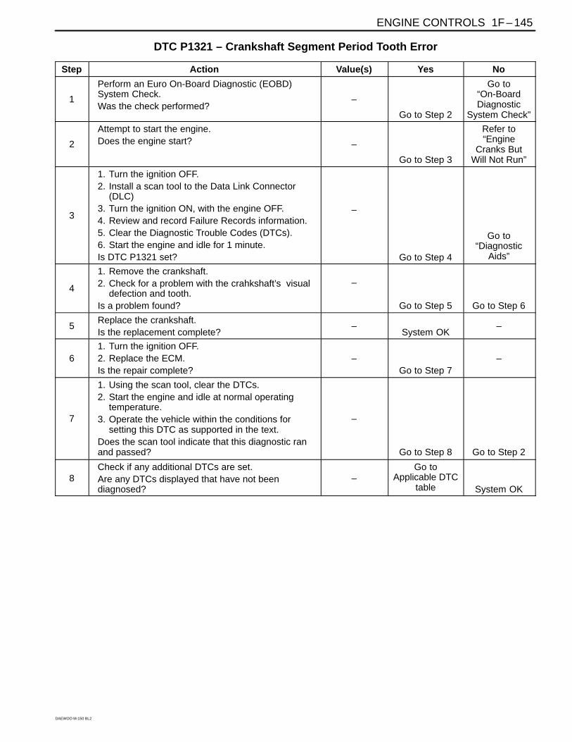
ENGINE CONTROLS 1F – 145
DAEWOO M-150 BL2
DTC P1321 – Crankshaft Segment Period Tooth Error
Step Action Value(s) Yes No
1
Perform an Euro On-Board Diagnostic (EOBD)System Check.Was the check performed?
–
Go to Step 2
Go to“On-BoardDiagnostic
System Check”
2
Attempt to start the engine.Does the engine start? –
Go to Step 3
Refer to“Engine
Cranks ButWill Not Run”
3
1. Turn the ignition OFF.2. Install a scan tool to the Data Link Connector
(DLC)3. Turn the ignition ON, with the engine OFF.4. Review and record Failure Records information.5. Clear the Diagnostic Trouble Codes (DTCs).6. Start the engine and idle for 1 minute.Is DTC P1321 set?
–
Go to Step 4
Go to“Diagnostic
Aids”
4
1. Remove the crankshaft.2. Check for a problem with the crahkshaft’s visual
defection and tooth.Is a problem found?
–
Go to Step 5 Go to Step 6
5Replace the crankshaft.Is the replacement complete?
–System OK
–
61. Turn the ignition OFF.2. Replace the ECM.Is the repair complete?
–Go to Step 7
–
7
1. Using the scan tool, clear the DTCs.2. Start the engine and idle at normal operating
temperature.3. Operate the vehicle within the conditions for
setting this DTC as supported in the text.Does the scan tool indicate that this diagnostic ranand passed?
–
Go to Step 8 Go to Step 2
8Check if any additional DTCs are set.Are any DTCs displayed that have not beendiagnosed?
–Go to
Applicable DTCtable System OK

1F – 146 ENGINE CONTROLS
DAEWOO M-150 BL2
MAA1F170
DIAGNOSTIC TROUBLE CODE (DTC) – P0327 KNOCK SENSOR CIRCUIT FAULTCircuit Description
The knock sensor(KS) system is used to detect enginedetonation, allowing the engine control module(ECM) toretard ignition control spark timing based on the KS sig-nal being received. The KS produces an AC signal sothat under a no knock condition the signal on the KS cir-cuit measures about 0.007V AC. The KS signal’s ampli-tude and frequency depend upon the amount of knockbeing experienced. The ECM contains a non-replace-able knock filter module called a signal-to-noise en-hancement filter (SNEF) module. This filter module inthe ECM determines whether knock is occurring bycomparing the signal level on the KS circuit with the volt-age level on the noise channel. The noise channel al-lows the ECM to reject any false knock signal byknowing the amount of normal engine mechanical noisepresent. Normal engine noise varies depending on en-gine speed and load. When the ECM determines that anabnormally low noise channel voltage level is being ex-perienced, a DTC P0327 will set.
Conditions for Setting the DTC
Knock sensor SPI bus in failure during 7 seconds.
The knock sensor voltage is below 0.2V.
Engine Coolant Temperature is higher than 80°C(176°F).
Engine rpm is more than 2,500rpm.
Mass air flow is higer than 180mg/tdc.
Action Taken When The DTCs Sets
The Malfunction Indicator Lamp (MIL) will illuminate.
The ECM will record operating conditions at the timethe diagnostic fails. This information will be stored inthe Freeze Frame and Failure Records buffers.
A history DTC is stored.
Conditions for Clearing the MIL/DTC
The MIL will turn off after four consecutive ignitioncycles in which the diagnostic runs without a fault.
A history DTC will clear after 40 consecutive warm-upcycles without a fault.
DTC(s) can be cleared by using the scan tool.
DIAGNOSTIC AIDS
Check and correct any abnormal engine noise beforeusing the diagnostic table.
Any circuitry that is suspected as causing engine noisecomplaint should be thoroughly checked for the follow-ing conditions :
Backed-out terminals.
Improper mating.
Broken locks.
Improperly formed.
Damaged terminals.
Poor terminal-to-wire connections.
Physical damage to the wiring harness.
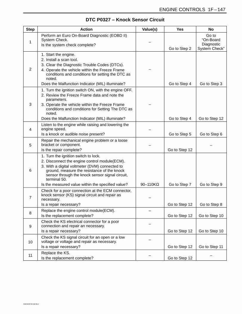
ENGINE CONTROLS 1F – 147
DAEWOO M-150 BL2
DTC P0327 – Knock Sensor Circuit
Step Action Value(s) Yes No
1
Perform an Euro On-Board Diagnostic (EOBD II)System Check.Is the system check complete?
–
Go to Step 2
Go to“On-BoardDiagnostic
System Check”
2
1. Start the engine.2. Install a scan tool.3. Clear the Diagnostic Trouble Codes (DTCs).4. Operate the vehicle within the Freeze Frame
conditions and conditions for setting the DTC asnoted.
Does the Malfunction Indicator (MIL) illuminate?
–
Go to Step 4 Go to Step 3
3
1. Turn the ignition switch ON, with the engine OFF.2. Review the Freeze Frame data and note the
parameters.3. Operate the vehicle within the Freeze Frame
conditions and conditions for Setting The DTC asnoted.
Does the Malfunction Indicator (MIL) illuminate?
–
Go to Step 4 Go to Step 12
4Listen to the engine while raising and lowering theengine speed.Is a knock or audible noise present?
–Go to Step 5 Go to Step 6
5Repair the mechanical engine problem or a loosebracket or component.Is the repair complete?
–Go to Step 12
–
6
1. Turn the ignition switch to lock.2. Disconnect the engine control module(ECM).3. With a digital voltmeter (DVM) connected to
ground, measure the resistance of the knocksensor through the knock sensor signal circuit,terminal 50.
Is the measured value within the specified value? 90–110KΩ Go to Step 7 Go to Step 9
7
Check for a poor connection at the ECM connector,knock sensor (KS) signal circuit and repair asnecessary.Is a repair necessary?
–
Go to Step 12 Go to Step 8
8Replace the engine control module(ECM).Is the replacement complete?
–Go to Step 12 Go to Step 10
9Check the KS electrical connector for a poorconnection and repair an necessary.Is a repair necessary?
–
Go to Step 12 Go to Step 10
10Check the KS signal circuit for an open or a lowvoltage or voltage and repair as necessary.Is a repair necessary?
–
Go to Step 12 Go to Step 11
11Replace the KS.Is the replacement complete?
–Go to Step 12
–

1F – 148 ENGINE CONTROLS
DAEWOO M-150 BL2
DTC P0327 – Knock Sensor Circuit (Cont’d)
Step Action Value(s) Yes No
12
1. Using the scan tool, clear the DTCs. Start the engine and idle at normal operating
temperature. Operate the vehicle within the conditions for
setting this DTC as specified in the supportingtext.
Does the scan tool indicate that this diagnostic hasrun and passed?
–
Go to Step 13 Go to Step 2
13Check if any additional DTCs are set.Are any DTCs displayed that have not beendiagnosed?
–Go to
Applicable DTCtable System OK

ENGINE CONTROLS 1F – 149
DAEWOO M-150 BL2
BLANK

1F – 150 ENGINE CONTROLS
DAEWOO M-150 BL2
MAA1F180
DIAGNOSTIC TROUBLE CODE (DTC) – P0335 MAGNETIC CRANKSHAFTPOSITION SENSOR ELECTRICAL ERROR
Circuit Description
The 58X reference signal is produced by the crankshaftposition (CKP) sensor. During one crankshaft revolu-tion, 58 crankshaft pulses will be produced. The enginecontrol module(ECM) uses the 58X reference signal tocalculate engine rpm and CKP. The ECM constantlymonitors the number of pulses on the 58X reference cir-cuit and compares them to the number of camshaft posi-tion (CKP) signal pulses being received. If the ECMreceive and incorrect number of pulses on the 58X refer-ence circuit, DTC P0335 will set.
Conditions for Setting the DTC
This DTC can be stored in “key-on” status.
Extra or missing pulses is detected between consec-utive 58X reference pulses.
The value of Magnetic Crankshaft position sensor ishigher than 0.2V.
The minimum value of Magnetic Crankshaft positionsensor is less than 1.5V.
The Maximum value of Magnetic Crankshaft positionsensor is higher than 2.2V.
Action Taken When the DTC Sets
The Malfunction Indicator Lamp (MIL) will illuminate.
The ECM will record operating conditions at the timethe diagnostic fails. This information will be stored inthe Freeze Frame and Failure Records buffers.
A history DTC is stored.
Conditions for Clearing the MIL/DTC
The MIL will turn off after four consecutive ignitioncycles in which the diagnostic runs without a fault.
A history DTC will clear after 40 consecutive warm-upcycles without a fault.
DTC(s) can be cleared by using the scan tool.
DIAGNOSTIC AIDS
An intermittent may be caused by a poor connection,rubbed-through wire insulation or a wire broken insidethe insulation. Check for :
Poor connection – inspect the ECM harness and con-nectors for improper mating, broken locks, improperlyformed or damaged terminals, and poor terminal-to-wireconnection.
Damaged harness – inspect the wiring harness for dam-age. If the harness appears to be OK, disconnect theECM, turn the ignition ON and observe a voltmeter con-nected to the 58X reference circuit at the ECM harnessconnector while moving the connectors and the wiringharness related to the ECM. A change in voltage will in-dicate the location of the fault.
Review the failure records vehicle mileage since thediagnostic test failed may help determine how often thecondition that caused the DTC to be set occurs. Thismay assist in diagnosing the condition.

ENGINE CONTROLS 1F – 151
DAEWOO M-150 BL2
DTC P0335 – Magnetic Crankshaft Position Sensor Electrical Error
Step Action Value(s) Yes No
1
Perform an Euro On-Board Diagnostic (EOBD)System Check.Is the system check complete?
–
Go to Step 2
Go to“On-BoardDiagnostic
System Check”
2
Attempt to start the engine.Does the engine start? –
Go to Step 3
Refer to“Engine
Cranks ButWill Not Run”
3
1. Review and record Failure Records information.2. Clear the DTC P0335.3. Start the engine and idle for 1 minute.4. Observe the diagnostic trouble codes (DTCs).Is the DTC P0335 set?
–
Go to Step 4
Go to“Diagnostic
Aids”
4
1. Disconnect the engine control module(ECM) andthe crankshaft position (CKP) sensor.
2. Check for an open or an open or short to groundin the CKP sensor connector and the ECMharness connector.
Is the problem found?
–
Go to Step 5 Go to Step 6
5
Repair the open or an open or short to ground in the58X reference circuit between the CKP sensorconnector and the ECM harness connector.Is the repair complete?
–
Go to Step 11
–
6
1. Reconnect the ECM and CKP sensor.2. Connect a digital voltmeter (DVM) to measure
voltage on the 58X reference circuit, terminal 54at the ECM connector.
3. Observe the voltage while cranking the engine.Is the voltage near the specified value? 2.5V Go to Step 9 Go to Step 7
7Check the connection at the CKP sensor andreplace the terminals if necessary.Do any terminals require replacement?
–Go to Step 11 Go to Step 8
8Replace the CKP sensor.Is the replacement complete?
–Go to Step 11
–
9Check the connections at the ECM and replace theterminals if necessary.Do any terminal require replacement?
–Go to Step 11 Go to Step 10
10Replace the ECM.Is the replacement complete?
–Go to Step 11
–
11
1. Using the scan tool, clear the DTCs.2. Start the engine and idle at normal operating
temperature.3. Operate the vehicle within the conditions for
setting this DTC as specified in the supportingtext.
Does the scan tool indicate that this diagnostic runand passed?
–
Go to Step 12 Go to Step 2
12Check if any additional DTCs are set.Are any DTCs displaced that have not beendiagnosed?
–Go to
Applicable DTCtable System OK