diameter distribution for a compressed air, nebulizer
TRANSCRIPT

DIAMETER DISTRIBUTION FOR A
COMPRESSED AIR, NEBULIZER
ATOMIZING SYSTEM
by
DAVID H. YOON
Submitted to the Department of Mechnical Engineeringin partial fulfillment of the requirements for the degree of
BACHELOR OF SCIENCE
at the
MASSACHUSETTS INSTITUTE OF TECHNOLOGY
February 1991
@ Massachusetts Institute of Technology 1991. All rights reserved.
Author .............................................Department of Mechnical Engineering
December 14, 1990
Certified by .......................................................John H. Lienhard VAssistant Professor
Thesis Supervisor
Accepted by ......................................................Peter Griffith
Chairman, Department Committee


DIAMETER DISTRIBUTION FOR A COMPRESSED
AIR, NEBULIZER ATOMIZING SYSTEM
by
DAVID H. YOON
Submitted to the Department of Mechnical Engineeringon December 14, 1990, in partial fulfillment of the
requirements for the degree ofBACHELOR OF SCIENCE
Abstract
An experimental study was conducted on the behavior of aerosol diameter distribu-tion for a compressed air, nebulizer atomizing system. A compressed air nebulizerhas been utilized to generate aerosols of liquid (water). The tests, under variousconditions, measured droplet diameters and velocities with a laser phase dopplerparticle-sizing system. Tests were also performed on nozzles and sprays atomizingsystem for comparison.
The results from the diameter distribution experiment showed that aerosol diametersincrease with an increase in both water and air tube sizes and diminish with anincrease in air pressure. Also, it was found that the geometry of the water tube,the radial distance of the measuring position from the air jet centerline, and thedownstream distance from the nebulizer all have significant effects on the aerosoldiameter distribution.
In addition, the physical mechanisms of atomization for the nebulizer is defined. Thevolume flow of liquid is driven by pressure drop in the water supply line, and the eddyat the tip of water tube is created by streamline curvature associated with blockage ofthe airstream. The eddy causes disturbance within water which initiates atomization.When the high velocity air jet shears the unstable water, the atomization becomescomplete. Finally, a theoretical relationship which predicts mean diameter for a fanspray atomizer was empirically modified to correlate with the present experimentaldata.
Thesis Supervisor: John H. Lienhard VTitle: Assistant Professor

Acknowledgments
I would like to thank, first of all, my supervisor Professor Lienhard for letting me
partake in his research in the Heat Transfer Lab. I'm truly grateful to him and his
research assistant, John Simo, for helping me through the research and having the
patience to put up with me. The experience that I have gained has been invaluable.
Also I would like express my utmost gratitude to Baker House Schmuckheads for the
fun times, to my parents for the support, and most of all, to God for being with me
... always.
This research was sponsored by the Electric Power Research Institute under
contract #RP8000-41 and by the National Science Foundation under grant
#CBTE-8858288.

Contents
1 Introduction
2 Preparation of Aerosol Generation
2.1 Measurement Apparatus - Laser Phase Doppler . . . . . . . . . . . .
2.2 Compressed Air Nebulizer ........................
2.3 Parameters of Compressed Air Nebulizer . . . . . . . . . . . . . . . .
3 Characterization of the Compressed Air Nebulizer
3.1 Effects of Different Parameters......................
3.2 Comparison with Other Atomizing Systems . . . . . . . . . . . . . .
4 Analysis of the Compressed Air Nebulizer
4.1 Physical Process of Nebulizer Atomization . . . . . . . . . . . . . . .
11
14
19
21
27
30
31

4.2 Calculation of Sauter Mean Diameter . ................. 33
5 Conclusion 38

List of Figures
2-1 PDPA Optical System ........................
2-2 Assembly of the Laser Phase Doppler System ..........
2-3 Tube Configuration for the Compressed Air Nebulizer . ...
2-4 Nebulizer Assembly Using an Aluminum Shaft .........
2-5 Adjustable Mounting Platform for the Nebulizer ........
2-6 Experiment Setup for the Compressed Air Nebulizer.....
3-1 Effects of Water Tube Size on Droplet Diameter ........
3-2 Effects of Air Tube Size on Droplet Diameter ..........
3-3 Effects of Water Tube Geometry on Droplet Diameter . .
3-4 Effects of Radial Distance from Airjet Centerline on Droplet
D iam eter ..... .. ......... .... ......... .. ..

3-5 Comparison with a Humidifier and the Effects of Downstream
Distance on Droplet Diameter ...................
3-6 Comparison of Compressed Air Nebulizer and Sprayer . . ..
4-1 Low Pressure at the Water Tube End ...............
4-2 Eddy Phenomenon in the Water Tube ..............
4-3 Completion of Nebulizer Atomization ...............
4-4 Correlation of Calculated SMD with Experimental Data . ..
Chapter 1
Introduction
Due to the development of certain industries, the need to analyze the behavior of
aerosols from different types of generators becomes essential. Industries involved in
studies of the physical and the chemical properties of particles, and the calibration
of particle-sampling and particle-sizing apparatus, are deeply interested in accurate
analysis of aerosol behavior. Other interested industries are associated with the eval-
uation of air and gas cleaning equipment where full scale field studies are not feasible.
Further, industries connected to air pollution control, powder manufacturing, spray
coating, and fuel injection are all seeking to characterize aerosol behavior. In addi-
tion, many institutions of medical research can use the information gathered from
the studies of aerosol behavior as well. The information can be used to improve the
efficiency of respiratory protection equipment and to advance researches associated
with inhalation, deposition, and exhalation of pulmonary particles. Such knowledge
can be applied, for instance, to finding solutions for the lung-damaging iron particles
near steel mills.
In light of such need, the purpose of this work has been to characterize the behavior of

aerosols from certain generators that can be used in other experiments. In particular,
the results of this research may be used in the experimental analysis of turbulent power
spectrum behavior and the extent of particle inertial effects for different diameters (1
- 40 microns) in turbulent flow.
In order to generate aerosols, the liquid droplets are dispersed by the mechanism
of liquid shearing; such generating systems are referred as "atomizers." The four
general classifications for atomizers are as follows: nozzles and sprays; nebulizers;
rotary generators; and mechanically vibrated systems.
Out of the four classes of atomizers, rotary generators and the mechanically vibrated
systems are not within the scope of this research and are not studied. For rotary
generators such as the spinning disk, the measurement apparatus is not appropriate
and the the diameters of the aerosols produced are beyond the range of interest.
The mechanically vibrated systems such as the piezoelectric crystal at the end of a
capillary tube is too costly and unreliable for small particle production owing to its
tendency to clog.
Compressed air nebulizers produce aerosols appropriate for this research and thus,
have been studied in depth. For comparison, another nebulizing atomizer, an ultra-
sonic humidifier, and several simple nozzle and spray atomizers have been studied
also.
What follows is a detailed description of the compressed air nebulizer design and the
measuring apparatus employed. The procedure and the results of the experiment are
discussed along with comparisons with different atomizers mentioned above. In addi-
tion, a theoretical analysis of the experiment is presented. Lastly, all the uncertainties
of the experiment are discussed as well.

Chapter 2
Preparation of Aerosol Generation
2.1 Measurement Apparatus - Laser Phase Doppler
To specifically characterize aerosol diameter distribution from different generators,
a measurement divice is needed. The Aerometrics Phase Doppler Particle Analyzer
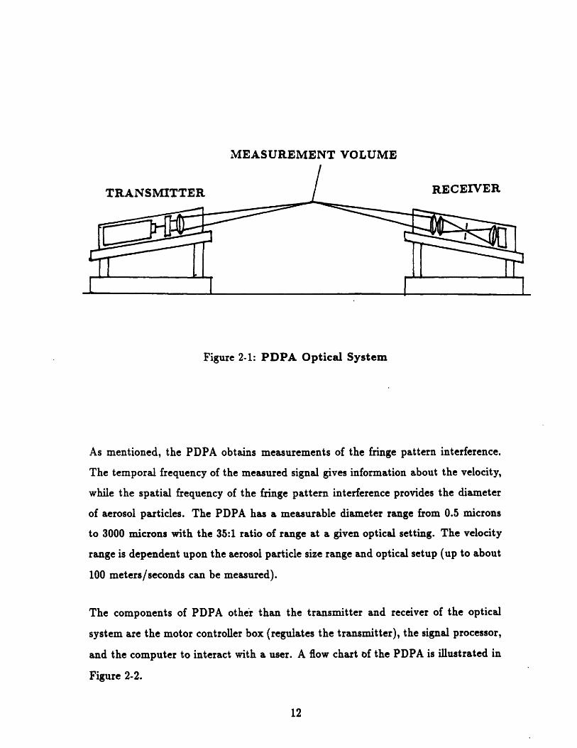
(PDPA) is the measuring device used. It utilizes the light scattering method to simul-
taneously obtain size and velocity measurements of the aerosol particles. The PDPA
uses an optical system consisting of a transmitter and receiver which reads the fringe
pattern interference produced by the scattered light. More specifically, the scatter-
ing of light occurs when the aerosol particles pass through the measurement volume
where the two laser beams from the transmitter intersect. A schematic diagram of
the PDPA optical system is shown in Figure 2-1.
MEASUREMENT VOLUME
Figure 2-1: PDPA Optical System
As mentioned, the PDPA obtains measurements of the fringe pattern interference.
The temporal frequency of the measured signal gives information about the velocity,
while the spatial frequency of the fringe pattern interference provides the diameter
of aerosol particles. The PDPA has a measurable diameter range from 0.5 microns
to 3000 microns with the 35:1 ratio of range at a given optical setting. The velocity
range is dependent upon the aerosol particle size range and optical setup (up to about
100 meters/seconds can be measured).
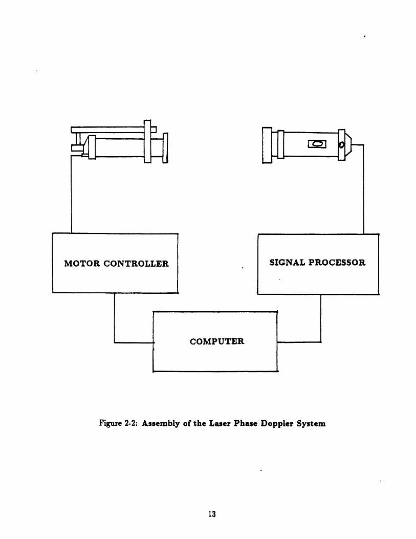
The components of PDPA other than the transmitter and receiver of the optical
system are the motor controller box (regulates the transmitter), the signal processor,
and the computer to interact with a user. A flow chart of the PDPA is illustrated in
Figure 2-2.
M(OTOR CONTROLLER SGA RCSO
Figure 2-2: Assembly of the Laser Phase Doppler System
COIMPUTER
SIGNAL PROCESSOR

2.2 Compressed Air Nebulizer
The type of compressed air atomizer studied is the venturi tubes shown in Figure 2-3.
It is comprised of two tubes whose ends are oriented perpendicular to each other. In
the experiment, water is drawn through one of the tubes while air is drawn through
the other. The material chosen for the air tube is copper while glass is selected for
the water tube. Initially, copper was used for material of both tubes, but in order to
observe the break-up phenomenon at the end of water tube, glass became the better
choice. However, a glass tube is harder to bend into the desired shape than a copper
tube. In order to bend a glass tube into the desired shape, it has to be heated until
it becomes ductile.
A problem arises when the air and water tubes have to be assembled together. There
are three different range of diameters (0.3175 cm, 0.635 cm, 0.9525 cm) for both the
air and water tubes. Also there are three different geometry shapes (regular (round),
horizontally pinched, vertically pinched) for the ends of water tube at each diameter of
the tube. With all these tubes, there are 27 different combinations of the compressed
air nebulizer. During the first stages of the experiment, an aluminum shaft was used
with two drilled holes to fit in the air and water tubes and then soldered to fix it, as
shown in Figure 2-4. However, with 27 combinations of the tubes to test, it became
apparent that there was a need for some sort of an adjustable mounting platform that
could accomodate all the different tube combinations. Hence, an adjustable mounting
platform was designed as demonstrated in Figure 2-5.

AIR N
WATER-gW
Figure 2-3: Tube Configuration for the Compressed Air Nebulizer
SOLDER
Figure 2-4: Nebulizer Assembly Using an Aluminum Shaft
flo=)
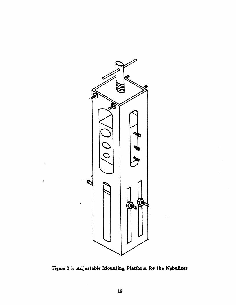
Figure 2-5: Adjustable Mounting Platform for the Nebulizer
16

This adjustable mounting platform can be analyzed in two sections. The top section
provides for the three different diameters of the air tubes to fit into the holes each with
a set screw to fix the tube at the position desired. Also, the rectangular aluminum
piece which holds the air tube can be moved vertically, to be at the necessary height
relative to water tube to produce aerosols. This is achieved by a simple screw type
linear motion mechanism much like a standard vice. It has a lever at the top that
can be easily controlled by the user.
The bottom section of the adjustable mounting platform allows the different water
tubes to fit into the slot. A slot rather than holes is needed to fit in the tubes, because
the water tube has a 90 degree turn at one end while attachments to the water supply
at the other end. The water tubes can be fixed to the top of the slot at the desired
position by the two small rods with nuts at its ends to tighten them.
With all the components of the experiment mentioned above assembled in correct
relation to one another, the measurements can now be taken on the compressed air,
nebulizer atomizing system. The compressed air supply comes from the in-house lab
compressors which range up to about 600 kPa. This pressure line is connected to the
air tube which has been swaged. The water supply is simply just a large flask filled
with water. Connecting the flask to the water tube is an ordinary rubber tubing.
One end of the rubber tubing is tightly fit over the water tube while the other end is
lowered to the flask. The entire setup of the experiment is shown in Figure 2-6.

AEROSOL
TRANSMITTER RECEIVER
COMPRESSED AIR
NEBULIZER
MOTOR
CONTROLLER
I IFigure 2-6: Experiment Setup for the Compressed Air Nebulizer
18
SIGNAL
PROCESSORCOMPUTER

2.3 Parameters of Compressed Air Nebulizer
Before generating aerosol particles, there are many aspects that must be considered.
The size of air tube has to be selected form a lot of 0.3175 cm, 0.635 cm, and 0.9525
cm. One end of the selected tube is swaged to be connected to the air supply and
then placed into the top section of the adjustable mounting platform. The size and
geometry of water tube has to be chosen also from three different size ranges of
0.3175 cm, 0.635 cm, and 0.9525 cm. The three different geometry orientations of the
water tube ends are regular (round), horizontally pinched, and vertically pinched. In
addition, the measurement volume (intersection of the two transmitting laser beams)
of the PDPA system has to be arranged such that the aerosols being measured are at
the position desired. In particular, the downstream distance and the radial distance
from the air jet centerline have to be considered. Finally, the pressure coming out of
the air tube has to be regulated. It is incrementally increased during the generation
of the aerosols starting at 137.9 kPa up to 551.6 kPa.

Chapter 3
Characterization of the
Compressed Air Nebulizer
For the atomizing system of compressed air nebulizer, the measurements taken by
PDPA are presented as histograms for diameters and velocities. The velocity mea-
surements are used as an indicator of consistency for the diameter measurements.
(Such inconsistency occur due to incorrect position of aerosols passing through the
measurement volume). The velocity measurement of droplets should increase with
each incremental increase of air pressure if all the other parameters remain the same.
However, if such direct relationship is not observed, then the diameter measurements
are not consistent from one to another. In compiling data, such inconsistent diameter
measurements are not taken into account.
In order to analyze how different parameters affect the diameter distribution, one
parameter would vary while others remain constant. The means of the diameter dis-
tribution have been compiled to indicate the occurence of trends. The mean diameter
is represented as sauter mean diameter, SMD, where it is expressed as
N N
SMD = Z n,D / Z nsD? (3.1)2=1 i=1
In this equation, n is the number of count and D is the actual size of the droplet
diameter in microns. For the compressed air nebulizer under study, the sauter mean
diameter seem to range between 13-18 microns.
3.1 Effects of Different Parameters
The effects of water tube size on the 1droplet sauter mean diameter is shown in Figure
3-1. The three different water tube diameters have been tested. The air tube has a
diameter of 0.635 cm and the water tubes has a regular (round) geometry. Also, the
measurements have been taken at the centerline of air jet and 17.78 cm downstream
from the nebulizer. The figure indicates that bigger diameters of the water tube
produce bigger diameters of aerosol. Further, as the air pressure increases, the aerosol
diameters decrease.
The Figure 3-2 shows the effects of air tube size on the droplet sauter mean diameter.
The three diameters of air tube have been studied while other parameters stayed the
same. The water tube utilized has a diameter of 0.635 cm and a regular (round)
geometry. Again, the measurements have been taken at the centerline of air jet and
17.78 cm downstream from the nebulizer. As shown, bigger diameters of air tube
produce bigger diameters of aerosol, and the aerosol diameters decrease as the air
pressure increases.

0=0.95cm
D=0.32cm
AIR TUBED=0.635cm
200 400 600
AIR PRESSURE kPa
Figure 3-1: Effects of Water Tube Size on Droplet Diameter
14
13rI _ I _
· · ·IJ
I

D=0.95cm
D=0.635cm
O
D=0.32cnb O0 O
0O
WATER TUBED=0.635cmgeometry: regular
(round)
200 400 600
AIR PRESSURE kPa
Figure 3-2: Effects of Air Tube Size on Droplet Diameter
17.5
15.0
12.5
·
I
• • • • JL

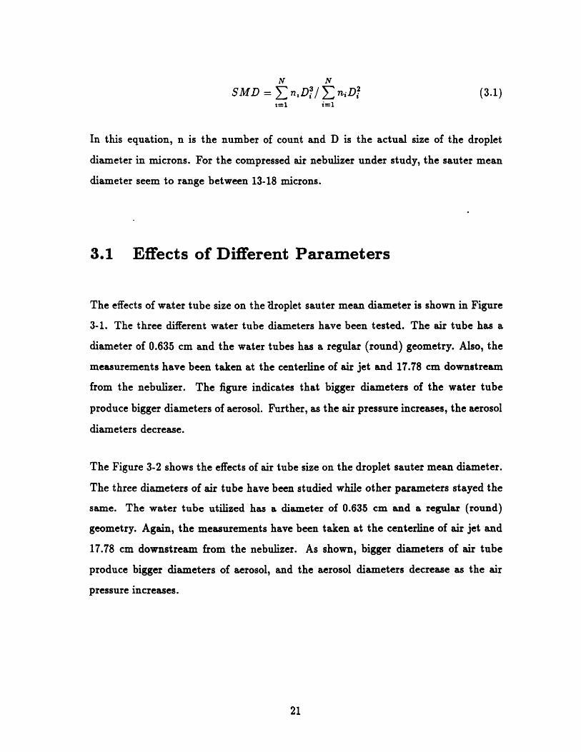
The influence of water tube geometry on the droplet size has been investigated by
obtaining measurements on three different geometries at the end of the water tube as
illustrated in Figure 3-3. The three different geometries of water tube end include:
regular (round); horizontally pinched (elongation of the pinch runs across the air tube
end); and vertically pinched (elongation of the pinch runs away from the air tube end).
The water tubes has a diameter of 0.635 cm while air tube also has a diameter of
0.635 cm. The measurements have been taken at the centerline of air jet and 17.78 cm
downstream from the nebulizer. The figure shows that the regular (round) geometry
produces largest size of aerosols, and the horizontally pinched geometry produces the
smallest size of aerosols. Again, the aerosol sizes decrease as the air pressure increases.
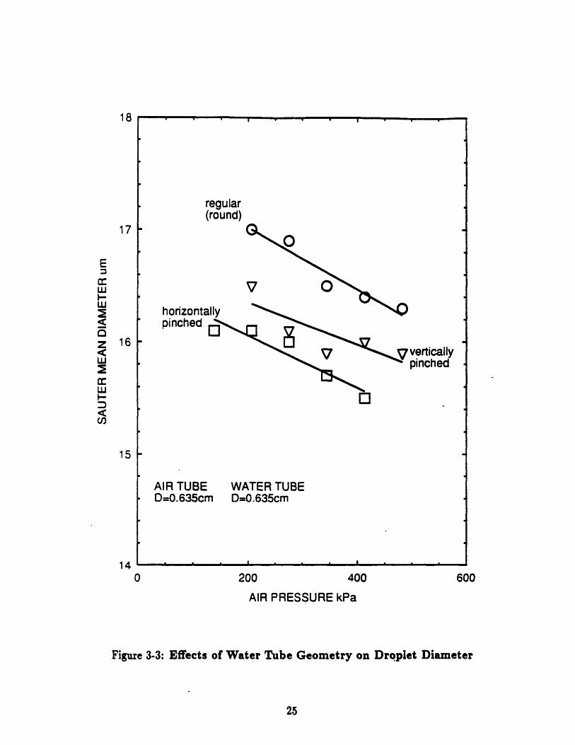
How the aerosol diameter is distributed along the radial distance from the air jet
centerline can be seen in the Figure 3-4. In this experiment, both the air and water
tube have diameters of 0.635 cm. Also, the water tube used has a regular (round)
geometry, and the air pressure is kept at 275.8 kPa. The measurements have been
taken 17.78 cm downstream from the nebulizer. The radial distance from centerline
has a negative effect on the size of aerosols produced. The largest aerosols are at the
centerline of air jet.
regular(round)
horizontallpinched I
verticallypinched
AIR TUBED=0.635cm
WATER TUBED=0.635cm
200 400 600AIR PRESSURE kPa
Figure 3-3: Effects of Water Tube Geometry on Droplet Diameter
• . . . = • .a
18
17
0 .5 1.0 1.5
RADIAL DISTANCE AWAY FROM CENTERLINE cm
Figure 3-4: Effects of Radial Distance from Airjet Centerline on DropletDiameter

3.2 Comparison with Other Atomizing Systems
The first comparison of aerosol sizes is made with a common household humidifier.
As noted in the Introduction, an ultrasonic humidifier is another type of nebulizing
atomizer. It utilizes a vibrating metal disk at the bottom of pool of water which at
certain frequencies causes water to atomize into aerosols at the surface. The Figure
3-5 shows the comparison. Smaller droplet sizes are produced by the humidifier. The
compressed air nebulizer has water tube and air tube diameters of 0.635 cm. The
water tube used has a regular (round) geometry, and the air pressure is kept at 275.8
kPa. The measurements have been taken at the centerline of air jet stream. The
Figure 3-5 also shows how the aerosol diameter is distributed along the downstream.
Probably due to the effects of gravity and evaporation, the droplet diameters decrease
as the downstream distance is increased.
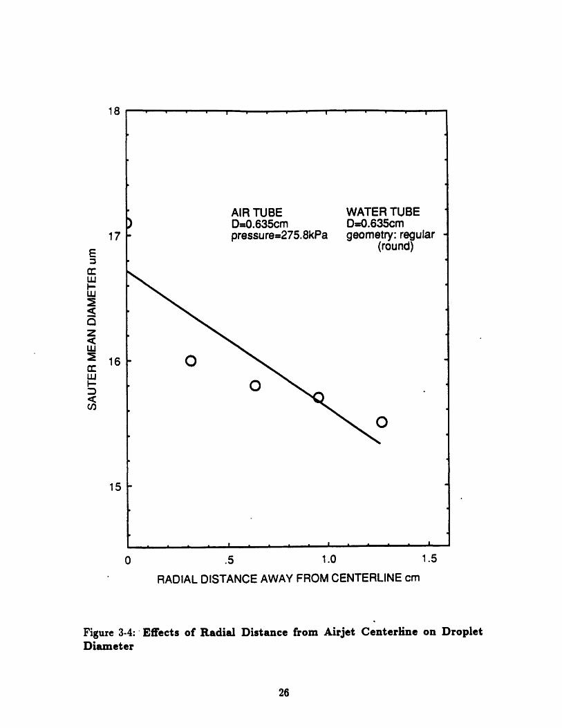
Another comparison of aerosol sizes is made with a commercial sprayer. The sprayer
comes from the Vortec Spray Vector System. It atomizes when water encouters high
velocity air in a chamber within the sprayer and is forced out of a nozzle. The com-
parison is shown in Figure 3-6. The compressed air nebulizer used in the comparison
has water and air tube diameters of 0.635 cm. It also has a water tube with a reg-
ular (round) geometry. The measurements have been taken at the centerline of air
jet stream and 17.78 cm downstream. The Figure 3-6 shows that the sprayer from
Vortec Spray Vector System produces aerosols with much larger diameters than the
compressed air nebulizer.

* I1
API I ulnD=0.635cmpressure=275.8kPa
)
WATER TUBED=0.635cmgeometry: regular
(round)
COMMON HOUSEHOLDHUMIDIFIER
O
20
DOWNSTREAM DISTANCE cm
Figure 3-5: Comparison with a Humidifier and the Effects of DownstreamDistance on Droplet Diameter
17
I
M ....
-
i ' i
"atomizing" sprayer
rI 11 1"!a-'
"fogging" sprayer
VORTECSPRAYVECTORSYSTEM
COMPRESSEDAIRNEBULIZER
WATER TUBED=0.635cmgeometry: regular
(round)
AIR TUBED=0.635cm
_ |
300 400 500
AIR PRESSURE kPa
Figure 3-6: Comparison of Compressed Air Nebulizer and Sprayer
20
200
_ 1
. ._ .... . .. , ,I I I I
F, C;,
I~ l i I -1 -

Chapter 4
Analysis of the Compressed Air
Nebulizer
Because of the complex nature of atomization, physical phenomenon involved in the
compressed air nebulizer must be studied. A pure mathematical treatment of the
subject would not be practical. In the experiment itself, much focus has been to-
ward different parameters that effect the diameter distribution. However, the focus
of obtaining reasonable relationship that could predict the mean diameter has to
be toward relevant properties of the fluid involved. Ultimately, it is these relevant
properties, combined with significant geometrical parameters of the compressed air
nebulizer that would determine the diameter distribution of the aerosols generated.
There has been much work done which describe the atomization process. Generally,
it is agreed that the liquid break up occurs not just by aerodynamic forces acting on
it, but also by turbulence or other disruptive forces within the liquid. Based on these
previous works, the nature of liquid break up for the compressed air nebulizer will be
considered.

4.1 Physical Process of Nebulizer Atomization
Atomization for the compressed air nebulizer under study can be divided into three
steps. Initially, air flows over the water tube at high velocity, causing low pressure
(less than atmospheric) at the tube end, which pulls the water through the tube.
This is shown in Figure 4-1. (See Appendix A for nomenclature).
PatSm
-In
Figure 4-1: Low Pressure at the Water Tube End
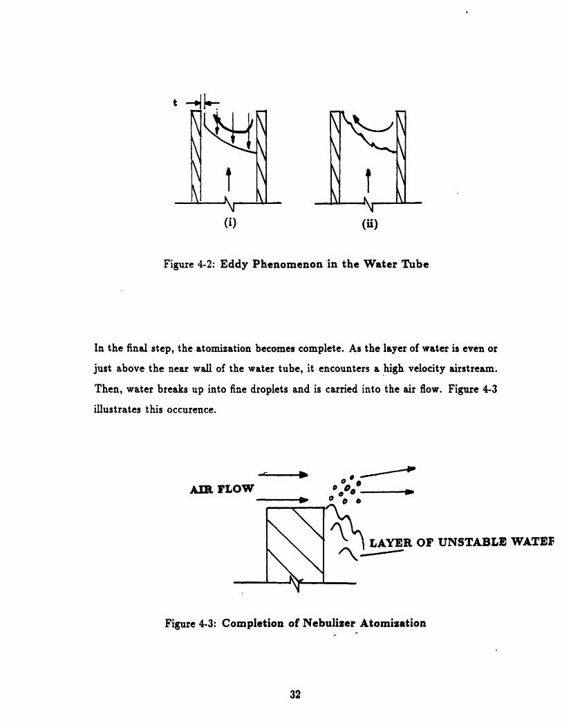
In the second step, some of the airstream is trapped by opposite wall of the water
tube, creating an eddy. The eddy causes a pressure gradient across the tube which
forces a layer of water with certain thickness to climb up the near side of the water
tube (Figure 4-2 (i)). The eddy also causes disturbances on the water surface through
ripples and waves (Figure 4-2 (ii)). The consequent instability of the water is the first
stage of atomization.
QW
II~CLIII
•T
(i) (ii)
Figure 4-2: Eddy Phenomenon in the Water Tube
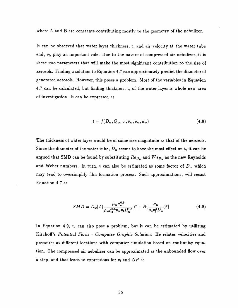
In the final step, the atomization becomes complete. As the layer of water is even or
just above the near wall of the water tube, it encounters a high velocity airstream.
Then, water breaks up into fine droplets and is carried into the air flow. Figure 4-3
illustrates this occurence.
AIR FLOW*
0*
SLAYER OF UNSTABLE WATEF
Figure 4-3: Completion of Nebulizer Atomization
-10.
mmammmamam•

4.2 Calculation of Sauter Mean Diameter
In order to establish an equation that can predict the sauter mean diameter of the
aerosols, all the variables are first accounted for. (See Appendix A for nomenclature)
SMD = f(Da, D., Patm, P, Qa, Q,vvt, v, V l,v , .,p V, l ,PaP, ,) (4.1)
Equation 4.1 expresses all the variables introduced in the description of physical
process (Section 4.1). However, not all of these variables are both independent and
important, and Equation 4.1 can be reduced to
SMD = f(vI, v., t, p., pW, 9A, a.) (4.2)
The variables expressed in Equation 4.2 can be further developed through dimensional
analysis. By utilizing the Reynolds and Weber numbers, the sauter mean diameter
is nondimensionalized into as
SMD--- oc [(Ret)(Wet)]- (4.3)
where,pRet= pvt povtRet ;Wet = -
At this point, a correlation developed by Wang and Lefebvre for a pressure-swirl noz-
zle (type of spray atomizer) can be adapted to the nebulizer. In their correlation,
Wang and Lefebvre divided their atomization process into two stages. The first stage
represents surface instabilities of the liquid and the second stage is actual formation

of droplets. As discussed in the description of physical process (Section 4.1), the at-
omization for the compressed air nebulizers can be divided into two stages in a similar
fashion. (It is important to note that such conclusion is an extreme simplication to
the atomization process). Thus, sauter mean diameter can be expressed as
SMD = SMD1 + SMD2 (4.4)
Since SMD1 represents the instabilities in the water surface, combination of the
Reynolds and Weber number can provide its estimate. The Reynolds number can
measure the disruptive force in the layer of water with thickness, t. The Weber number
can quantify the development of ripples on the layer of water surface. Consequently,
an expression for the SMD1 can be
SM D1(4.5)
t oc
For SMD2 , the completion of atomization process has to by quantified. It involves
high velocity airstream shearing a layer of water into fine droplets. The water surface
tension force opposes this action, and the Reynolds number is no longer relevant.
SMD2 can be expressed as
SMD2_- oc (Wet) - y (4.6)
Using appropriate substitutions, equation 4.4 can be expressed as
SMD = [A( + B( )] (4.7)
where A and B are constants contributing mostly to the geometry of the nebulizer.
It can be observed that water layer thickness, t, and air velocity at the water tube
end, vi, play an important role. Due to the nature of compressed air nebulizer, it is
these two parameters that will make the most significant contribution to the size of
aerosols. Finding a solution to Equation 4.7 can approximately predict the diameter of
generated aerosols. However, this poses a problem. Most of the variables in Equation
4.7 can be calculated, but finding thickness, t, of the water layer is whole new area
of investigation. It can be expressed as
t = f(Dw, Q,, vj, vw, pw, , ) (4.8)
The thickness of water layer would be of same size magnitude as that of the aerosols.
Since the diameter of the water tube, D, seems to have the most effect on t, it can be
argued that SMD can be found by substituting ReD. and WeD,,, as the new Reynolds
and Weber numbers. In turn, t can also be estimated as some factor of Dw which
may tend to oversimplify film formation process. Such approximations, will recast
Equation 4.7 as
05
SMD = D,[A( oDs ) (spwpn jv vD', pv•D= )"] (4.9)PwPa.sw PavQD
In Equation 4.9, v, can also pose a problem, but it can be estimated by utilizing
Kirchoff's Potential Flows - Computer Graphic Solution. He relates velocities and
pressures at different locations with computer simulation based on continuity equa-
tion. The compressed air nebulizer can be approximated as the unbounded flow over
a step, and that leads to expressions for vi and AP as

-- 1.2 (4.10)
AP = Pt, - P1 z 0.22pv 2 (4.11)
The velocity of water, v,, can be found by the head loss equation for a fully developed,
steady flow through a pipe. It is expressed as
1 2 AWLvwAP = pH + 2 32, D (4.12)
In Equation 4.12, H is the height from tip of the water tube to the water supply, and
L is the horizontal length of the water tube. It also utilizes pressure differential, AP,
found by Equation 4.11.
Now, sauter mean diameter of the compressed air nebulizer can be solved empirically.
Iteration of the experimental data gives values for exponents x and y of 0.8 and 1.2
respectively. Finding good correlation for the nebulizer with regular (round) geometry
of water tube yields values for constants A of 6.34 and B of 0.85. The results of all
the necessary calculations are presented in Appendix B. The correlation of Equation
4.9 with the experimental data is shown in Figure 4-4.

20.0
17.5
15.0
12.5
12.5 15.0 17.5 20.0
MEASURED SAUTER MEAN DIAMETER um
Figure 4-4: Correlation of Calculated SMD with Experimental Data

Chapter 5
Conclusion
A study on the behavior of aerosols from a certain type of generator has been con-
ducted. The aerosol generator utilized is a compressed air, nebulizer atomizing sys-
tem. It produced aerosols in the range of 10-20 microns. The experiments conducted
proved that many different parameters can have effect on the diameter distribution.
Such parameters are air pressure, tube sizes, tube geometry, and the aerosol position.
In addition to the compressed air nebulizer, several other types of atomizers have
been studied. A common household humidifier provided a good comparison, because
it also is a nebulizer (ultrasonic nebulizer). Further, a commercial sprayer system has
been studied as well. It belongs to nozzles and sprays atomizing category which is
the most typical aerosol generator. The Vortec Spray Vector System provided a good
contrast to the compressed air nebulizer. Other atomizers studied not mentioned in
the report include a hand pump sprayer, electric paint sprayer, and precision orifice
nozzles. These atomizers all yielded useful information in understanding of aerosol
behavior.

The theoretical model developed for the compressed air nebulizer is a rough estimation
of its actual behavior. However, many useful insights have been gained through its
development. The atomization process is much too complex for quantifying its mean
diameter with much accuracy. Hence, the analysis of atomization has to be based
on physical process. A correlation derived in Section 4.2 provides a good starting
point for further studies. Also, usage of liquid other than water will provide better
understanding of the extent of effects that liquid properties have on aerosol behavior.
It's essential that aerosols from all different types of atomizers can be analyzed accu-
rately. There are many more uses for the aerosols than what is currently employed by
some industries. Development of new industries and these current medical and com-
mercial industries depend wholly on the deeper knowledge and better understanding
of aerosol technology.

Appendix A
Nomenclature
A,B = constants
Da = air tube diameter, m
D= = water tube diameter, m
Pa = regulated air pressure of nebulizer, Pa
Ptm = atmospheric pressure, Pa
Pt = low pressure at the end of water tube, Pa
AP = pressure differential (Patm - Pr), Pa
Qa = volume flow rate of air, m 3/s
Q = = volume flow rate of water, m 3 /s
Re = Reynolds number
SMD = Sauter Mean Diameter, m
t = thickness of water layer, m
Va = air velocity coming out of its tube, m/s
vt = air velocity at the water tube end, m/s

v, = water velocity coming out of its tube, m/s
We = Weber number
pI = dynamic viscosity of air, kg/ms
pA = dynamic viscosity of water, kg/ms
pa = density of air, kg/m3
p, = density of water, kg/m 3
•, = surface tension of water, kg/s 2
Properties of Air and Water
p. = 1.81E-5 kg/ms
p, = 1.31E-3 kg/ms
p. = 1.21 kg/rm3
p. = 1000 kg/m 3
, = 7.42E-2 kg/s 2
Appendix B
Calculation of Sauter Mean Diameter
(Da = 3.175E-3 m) (D, = 3.175E-3 m)
v,(m,/) v A(m/r) OP(hP,)
56.1 46.8 3.81
63.8 53.2 4.93
71.5 59.6 6.19
79.8 66.5 7.71
83.5 69.6 8.44
87.6 73.0 9.29
U.(,/,)
1.36
1.82
2.25
2.71
2.91
3.13
$MDs,,(wMn)SMDeD,,I s("n)
14.2 14.1
14.0 13.9
13.7 13.7
13.6 13.4
12.9 13.3
13.1 13.2
(Da = 6.35E-3 m) (D, = 6.35E-3 m)
Q.(m'I,5%) .(m/l) vt(m/,) AP(hPa)
2.77E-3
3.09E-3
3.35E-3
3.72E-3
4.04E-3
87.4
97.5
105.7
117.4
127.4
72.8
81.3
88.1
97.8
106.2
9.24
11.50
13.52
16.68
19.64
uw(m/) SMD..,s(m) SMD.,g.(pm)
3.67
4.21
4.65
5.26
5.77
17.4
16.9
16.5
16.4
16.3
17.3
17.1
16.7
16.5
16.2
P.&(OP.) Q.(nis/)
137.9
206.8
275.8
344.7
413.7
482.6
4.44E-4
5.05E-4
5.66E-4
6.32E-4
6.61E-4
6.94E-4
206.8
275.8
344.7
413.7
482.6
(D, = 9.525E-3 m) (D, = 9.525E-3 m)
P.(kP}) Q.(m' /#) v.(m/e) u,(m/a) AP(kPa) 9,(r/.) SMD..t(Am) SMD..I.(iAm)
206.8 3.22E-3 45.2 37.7 2.47 1.09 18.0 18.2
275.8 3.53E-3 49.5 41.3 2.96 1.57 17.7 18.0
344.7 3.85E-3 54.0 45.0 3.53 1.78 17.6 17.7
413.7 4.10E-3 57.7 47.9 4.00 2.01 17.3 17.4
482.6 4.98E-3 69.8 58.2 5.90 2.77 17.2 17.1

Bibliography
1. Corn, M., and Esmen, N.A., Handbook on Aerosols, Prentice Hall, New York,
1982.
2. Drazin, P.G., and Reid, W.H., Hydrodynamic Stability, Cambridge University
Press, New York, 1981.
3. Fuchs, N.A., The Mechanics of Aerosols, Dover Press, New York, 1989.
4. Katz, M.B., "Minimum Particle Diameters of Selected Aqueous Aerosols," MIT
Thesis for Master of Science in Chemical Engineering Department, 1976.
5. Kaye, B.H., Direct Characterization of Fine Particles, Wiley, New York, 1981.
6. Kirchhoff Robert H., Potential Flows - Computer Graphic Solutions, Marcel
Dekker, Inc., New York, 1985.
7. Liu, B.Y., Fine Particles: aerosol generation, measurement, sampling, and anal-
ysis, Academic Press, New York 1976.
8. Philip, M.A., "An Absolute Method for Aerosol Particle Mass Measurement,"
MIT Thesis for Master of Science in Chemical Engineering Department, 1981.
9. Rockwell, D., and Naudascher, E., "Review - Self Sustaining Oscillatioins of
Flow Past Cavities," Journal of Fluids Engineering, Vol. 100, June, 1976, pp
152-165.
10. Sanders, P.A., Handbook of Aerosol Technology, Van Nostrand Reinhold Co.,
New York, 1979.
11. Seid, A., "Particle Size Distributions and Stability of Aqueous Aerosol," MIT
Thesis for Master of Science in Chemical Engineering Department, 1975.
12. Snyder, H.E., Senser, D.W., and Lefebvre, A.H., 1989, "Mean Drop Sizes From
Fan Spray Atomizers," Journal of Fluids Engineering, Vol. 111, September,
1989, pp. 342-347.

13. Suyari, M., and Lefebvre, A.H., "Film Thickness Measurements in a Simplex
Swirl Atomizer," AIAA Journal of Propulsion and Power, Vol. 2, Nov.-Dec.,
1986, pp. 528-533.
14. Wang, X.F., Lefebvre, A.H., "Mean Drop Sizes From Pressure-Swirl Nozzles,"
AIAA Journal of Propulsion and Power, Vol. 3, Jan.-Feb., 1987, pp. 11-18.