diameter user's guide - oracle
TRANSCRIPT

Diameter Signaling RouterDiameter User's Guide
Release 8.2
E88998
January 2018

Diameter Signaling Router Diameter User's Guide, Release 8.2
E88998
Copyright © 2011, 2018, Oracle and/or its affiliates. All rights reserved.
This software and related documentation are provided under a license agreement containing restrictions onuse and disclosure and are protected by intellectual property laws. Except as expressly permitted in yourlicense agreement or allowed by law, you may not use, copy, reproduce, translate, broadcast, modify, license,transmit, distribute, exhibit, perform, publish, or display any part, in any form, or by any means. Reverseengineering, disassembly, or decompilation of this software, unless required by law for interoperability, isprohibited.
The information contained herein is subject to change without notice and is not warranted to be error-free. Ifyou find any errors, please report them to us in writing.
If this is software or related documentation that is delivered to the U.S. Government or anyone licensing it onbehalf of the U.S. Government, then the following notice is applicable:
U.S. GOVERNMENT END USERS: Oracle programs, including any operating system, integrated software,any programs installed on the hardware, and/or documentation, delivered to U.S. Government end users are"commercial computer software" pursuant to the applicable Federal Acquisition Regulation and agency-specific supplemental regulations. As such, use, duplication, disclosure, modification, and adaptation of theprograms, including any operating system, integrated software, any programs installed on the hardware,and/or documentation, shall be subject to license terms and license restrictions applicable to the programs.No other rights are granted to the U.S. Government.
This software or hardware is developed for general use in a variety of information management applications.It is not developed or intended for use in any inherently dangerous applications, including applications thatmay create a risk of personal injury. If you use this software or hardware in dangerous applications, then youshall be responsible to take all appropriate fail-safe, backup, redundancy, and other measures to ensure itssafe use. Oracle Corporation and its affiliates disclaim any liability for any damages caused by use of thissoftware or hardware in dangerous applications.
Oracle and Java are registered trademarks of Oracle and/or its affiliates. Other names may be trademarks oftheir respective owners.
Intel and Intel Xeon are trademarks or registered trademarks of Intel Corporation. All SPARC trademarks areused under license and are trademarks or registered trademarks of SPARC International, Inc. AMD, Opteron,the AMD logo, and the AMD Opteron logo are trademarks or registered trademarks of Advanced MicroDevices. UNIX is a registered trademark of The Open Group.
This software or hardware and documentation may provide access to or information about content, products,and services from third parties. Oracle Corporation and its affiliates are not responsible for and expresslydisclaim all warranties of any kind with respect to third-party content, products, and services unlessotherwise set forth in an applicable agreement between you and Oracle. Oracle Corporation and its affiliateswill not be responsible for any loss, costs, or damages incurred due to your access to or use of third-partycontent, products, or services, except as set forth in an applicable agreement between you and Oracle.
This documentation is in preproduction status and is intended for demonstration and preliminary use only. Itmay not be specific to the hardware on which you are using the software. Oracle Corporation and its affiliatesare not responsible for and expressly disclaim all warranties of any kind with respect to this documentationand will not be responsible for any loss, costs, or damages incurred due to the use of this documentation.
The information contained in this document is for informational sharing purposes only and should beconsidered in your capacity as a customer advisory board member or pursuant to your beta trial agreementonly. It is not a commitment to deliver any material, code, or functionality, and should not be relied upon inmaking purchasing decisions. The development, release, and timing of any features or functionalitydescribed in this document remains at the sole discretion of Oracle.
This document in any form, software or printed matter, contains proprietary information that is the exclusiveproperty of Oracle. Your access to and use of this confidential material is subject to the terms and conditionsof your Oracle Master Agreement, Oracle License and Services Agreement, Oracle PartnerNetworkAgreement, Oracle distribution agreement, or other license agreement which has been executed by you andOracle and with which you agree to comply. This document and information contained herein may not bedisclosed, copied, reproduced, or distributed to anyone outside Oracle without prior written consent ofOracle. This document is not part of your license agreement nor can it be incorporated into any contractualagreement with Oracle or its subsidiaries or affiliates.

Contents
1 Introducing Diameter
Revision History ....................................................................................................................................... 1-1
Overview of Diameter Signaling Router Tasks .................................................................................... 1-2
Intended Scope and Audience ................................................................................................................ 1-3
Content Organization............................................................................................................................... 1-3
Documentation Admonishments ........................................................................................................... 1-4
Related Publications ................................................................................................................................. 1-4
Locate Product Documentation on the Oracle Help Center Site ....................................................... 1-4
Customer Training.................................................................................................................................... 1-5
My Oracle Support (MOS)....................................................................................................................... 1-5
Emergency Response................................................................................................................................ 1-5
2 User Interface Introduction
User Interface Organization .................................................................................................................... 2-1
User Interface Elements................................................................................................................... 2-2
Main Menu Options ......................................................................................................................... 2-4
Missing Main Menu options ................................................................................................................... 2-9
Common Graphical User Interface Widgets ......................................................................................... 2-9
Supported Browsers......................................................................................................................... 2-9
System Login Page ........................................................................................................................... 2-9
Main Menu Icons............................................................................................................................ 2-11
Work Area Displays ....................................................................................................................... 2-12
Customizing the Splash Page Welcome Message...................................................................... 2-14
Column Headers (Sorting) ............................................................................................................ 2-15
Page Controls .................................................................................................................................. 2-15
Clear Field Control ......................................................................................................................... 2-16
Optional Layout Element Toolbar................................................................................................ 2-16
Filters................................................................................................................................................ 2-17
Pause Updates................................................................................................................................. 2-20
Max Records Per Page Controls ................................................................................................... 2-20
iii

3 Configuring Diameter
Understanding the Diameter Configuration Sequence....................................................................... 3-1
Next Generation Network Priority Service (NGN-PS)........................................................................ 3-3
Diameter Overload Indication Conveyance (DOIC) ........................................................................... 3-6
Diameter Capacity Summary................................................................................................................ 3-10
Diameter Capacity Constraints .................................................................................................... 3-11
Connection Capacity Dashboard Functions ....................................................................................... 3-20
Validating Diameter Connection Capacity ................................................................................. 3-23
Using Application IDs to Identify Diameter Applications............................................................... 3-26
Diameter Application IDs elements ............................................................................................ 3-27
Adding an Application ID ............................................................................................................ 3-28
Editing an Application ID ............................................................................................................. 3-28
Deleting an Application ID ........................................................................................................... 3-29
Diameter CEX Parameters..................................................................................................................... 3-29
Diameter CEX Parameters elements............................................................................................ 3-30
Adding CEX Parameters ............................................................................................................... 3-30
Editing CEX Parameters ................................................................................................................ 3-31
Deleting CEX Parameters.............................................................................................................. 3-31
Diameter Command Codes................................................................................................................... 3-32
Diameter Command Codes elements.......................................................................................... 3-33
Adding a Command Code............................................................................................................ 3-33
Editing a Command Code............................................................................................................. 3-34
Deleting a Command Code........................................................................................................... 3-34
Diameter Configuration Sets................................................................................................................. 3-34
Diameter Connection Configuration Sets ................................................................................... 3-36
CEX Configuration Sets................................................................................................................. 3-48
Capacity Configuration Sets ......................................................................................................... 3-52
Egress Message Throttling Configuration Sets .......................................................................... 3-57
Message Priority Configuration Sets ........................................................................................... 3-60
Message Copy Configuration Sets ............................................................................................... 3-63
Rate Limiting Configuration Sets................................................................................................. 3-66
Pending Transaction Limiting Configuration Sets .................................................................... 3-71
Transaction Configuration Sets .................................................................................................... 3-74
Traffic Throttle Point Configuration Sets .................................................................................... 3-79
Diameter Local Nodes............................................................................................................................ 3-82
Diameter Local Node configuration elements ........................................................................... 3-84
Adding a Local Node..................................................................................................................... 3-91
Editing a Local Node ..................................................................................................................... 3-92
Deleting a Local Node ................................................................................................................... 3-93
Diameter Peer Nodes ............................................................................................................................. 3-94
Diameter Peer Node configuration elements ............................................................................. 3-95
Adding a Peer Node .................................................................................................................... 3-101
iv

Editing a Peer Node ..................................................................................................................... 3-106
Deleting a Peer Node ................................................................................................................... 3-107
Diameter Peer Node Groups............................................................................................................... 3-108
Diameter Peer Node Groups configuration elements............................................................. 3-109
Adding Peer Node Groups ......................................................................................................... 3-109
Editing Peer Node Groups.......................................................................................................... 3-110
Deleting Peer Node Groups........................................................................................................ 3-111
Connections ........................................................................................................................................... 3-111
IPFE Connections and Capacity Validation.............................................................................. 3-112
Diameter Connection configuration elements ......................................................................... 3-114
Adding a Connection................................................................................................................... 3-128
Editing a Connection ................................................................................................................... 3-130
Deleting a Connection ................................................................................................................. 3-131
Diameter Route Groups ....................................................................................................................... 3-132
Diameter Route Group configuration elements....................................................................... 3-132
Adding a Route Group ................................................................................................................ 3-134
Editing a Route Group................................................................................................................. 3-136
Deleting a Route Group............................................................................................................... 3-137
Diameter Route Lists ............................................................................................................................ 3-137
Diameter Route List configuration elements............................................................................ 3-138
Adding a Route List ..................................................................................................................... 3-140
Editing a Route List...................................................................................................................... 3-141
Deleting a Route List.................................................................................................................... 3-142
Diameter Peer Route Tables ................................................................................................................ 3-142
Diameter Peer Route Tables elements ....................................................................................... 3-143
Adding a Peer Route Table ......................................................................................................... 3-143
Deleting a Peer Route Table ........................................................................................................ 3-144
Peer Routing Rules configuration.............................................................................................. 3-145
Diameter Egress Throttle Groups....................................................................................................... 3-154
Diameter Egress Throttle Groups elements.............................................................................. 3-155
Adding Egress Throttle Groups ................................................................................................. 3-156
Editing Egress Throttle Groups.................................................................................................. 3-158
Deleting Egress Throttle Groups................................................................................................ 3-159
Diameter Reroute On Answer ............................................................................................................ 3-159
Diameter Reroute On Answer configuration elements .......................................................... 3-160
Adding a Reroute On Answer entry ......................................................................................... 3-160
Deleting a Reroute On Answer .................................................................................................. 3-161
Diameter Application Route Tables ................................................................................................... 3-161
Diameter Application Route Tables elements .......................................................................... 3-162
Adding an Application Route Table .......................................................................................... 3-162
Deleting an Application Route Table......................................................................................... 3-163
Application Routing Rules configuration................................................................................. 3-164
Diameter Routing Option Sets ............................................................................................................ 3-171
v

Diameter Routing Option Sets elements................................................................................... 3-172
Adding a Routing Option Set ..................................................................................................... 3-181
Editing a Routing Option Set...................................................................................................... 3-182
Deleting a Routing Option Set.................................................................................................... 3-182
Diameter Pending Answer Timers..................................................................................................... 3-182
Diameter Pending Answer Timers elements............................................................................ 3-187
Adding a Pending Answer Timer .............................................................................................. 3-187
Editing a Pending Answer Timer............................................................................................... 3-188
Deleting a Pending Answer Timer............................................................................................. 3-188
Diameter Traffic Throttle Points ......................................................................................................... 3-188
Diameter Traffic Throttle Point elements.................................................................................. 3-190
Adding Traffic Throttle Points.................................................................................................... 3-191
Editing Traffic Throttle Points .................................................................................................... 3-191
Deleting Traffic Throttle Points .................................................................................................. 3-191
Diameter Traffic Throttle Groups ....................................................................................................... 3-192
Diameter Traffic Throttle Groups elements .............................................................................. 3-193
Adding Traffic Throttle Groups.................................................................................................. 3-193
Editing Traffic Throttle Groups .................................................................................................. 3-194
Deleting Traffic Throttle Groups ................................................................................................ 3-194
Diameter AVP Removal Lists.............................................................................................................. 3-195
Diameter AVP Removal Lists elements..................................................................................... 3-195
Adding AVP Removal Lists ........................................................................................................ 3-196
Editing AVP Removal Lists......................................................................................................... 3-197
Deleting AVP Removal Lists....................................................................................................... 3-197
Diameter Application Priority Options ............................................................................................. 3-197
Diameter Application Priority Options elements.................................................................... 3-198
Adding Application Priority Options ....................................................................................... 3-199
Editing Application Priority Options ........................................................................................ 3-199
Deleting Application Priority Options ...................................................................................... 3-200
Diameter System Options.................................................................................................................... 3-200
Diameter System Options elements........................................................................................... 3-200
Editing System Options............................................................................................................... 3-209
Diameter DNS Options ........................................................................................................................ 3-209
Diameter DNS Options elements............................................................................................... 3-209
Editing DNS Options ................................................................................................................... 3-210
Diameter Peer Discovery ..................................................................................................................... 3-210
Realms............................................................................................................................................ 3-211
DNS Sets ........................................................................................................................................ 3-216
Discovery Attributes .................................................................................................................... 3-219
4 Diameter Maintenance
Diameter Maintenance Overview .......................................................................................................... 4-1
Diameter Maintenance Route Lists ........................................................................................................ 4-1
vi

Diameter Route List maintenance elements ................................................................................. 4-2
Diameter Maintenance Route Groups ................................................................................................... 4-3
Diameter Route Group maintenance elements ............................................................................ 4-3
Diameter Maintenance Peer Nodes........................................................................................................ 4-4
Diameter Peer Node maintenance elements ................................................................................ 4-5
Diameter Maintenance Connections...................................................................................................... 4-6
Diameter Connection maintenance elements............................................................................... 4-6
Enabling Connections .................................................................................................................... 4-10
Enabling All Connections.............................................................................................................. 4-10
Disabling Connections................................................................................................................... 4-10
Disabling All Connections ............................................................................................................ 4-11
Connections SCTP Statistics.......................................................................................................... 4-11
Starting Diagnosis on a Test Connection .................................................................................... 4-12
Ending Diagnosis on a Test Connection...................................................................................... 4-13
Diameter Maintenance Egress Throttle Groups ................................................................................. 4-13
Diameter Egress Throttle Groups maintenance elements ........................................................ 4-15
Enabling Egress Throttle Groups Rate Limiting........................................................................ 4-17
Disabling Egress Throttle Groups Rate Limiting....................................................................... 4-18
Enabling Egress Throttle Groups Pending Transaction Limiting............................................ 4-19
Disabling Egress Throttle Groups Pending Transaction Limiting .......................................... 4-20
Diameter Maintenance Applications ................................................................................................... 4-20
Diameter Applications maintenance elements .......................................................................... 4-21
Enabling Applications ................................................................................................................... 4-21
Disabling Applications .................................................................................................................. 4-22
Diameter Maintenance DA-MPs........................................................................................................... 4-22
Diameter DA-MPs maintenance elements.................................................................................. 4-23
Diameter Maintenance Peer Discovery ............................................................................................... 4-25
Diameter Peer Discovery maintenance elements ...................................................................... 4-25
Enabling Peer Discovery ............................................................................................................... 4-26
Disabling Peer Discovery .............................................................................................................. 4-27
Refreshing Peer Discovery ............................................................................................................ 4-27
Extending Peer Discovery ............................................................................................................. 4-28
Diameter Maintenance Signaling Firewall.......................................................................................... 4-28
Diameter Signaling Firewall maintenance elements................................................................. 4-29
Enabling Signaling Firewall Nodes ............................................................................................. 4-29
Disabling Signaling Firewall Nodes ............................................................................................ 4-30
Diameter Maintenance Traffic Throttle Points ................................................................................... 4-30
Diameter Traffic Throttle Points Maintenance elements .......................................................... 4-31
Diameter Maintenance Traffic Throttle Groups ................................................................................. 4-32
Diameter Traffic Throttle Groups elements ................................................................................ 4-33
Enabling Traffic Throttle Groups ................................................................................................. 4-33
Enabling All Traffic Throttle Groups ........................................................................................... 4-34
Disabling Traffic Throttle Groups ................................................................................................ 4-35
vii

Disabling All Traffic Throttle Groups.......................................................................................... 4-35
5 Diameter Reports
Overview.................................................................................................................................................... 5-1
Diameter Diagnostics Tool....................................................................................................................... 5-1
Viewing, Printing, and Saving Diagnostics Tool Reports........................................................... 5-2
Diameter MP Statistics (SCTP)................................................................................................................ 5-3
MP Statistics (SCTP) Report elements........................................................................................... 5-4
6 Troubleshooting with IDIH ................................................................................... 6-1
7 Diameter AVP Dictionary
AVP Flags ................................................................................................................................................... 7-1
Base Dictionary ......................................................................................................................................... 7-2
Diameter Base Dictionary elements............................................................................................... 7-3
Cloning AVP entries......................................................................................................................... 7-4
Custom Dictionary.................................................................................................................................... 7-4
Diameter Custom Dictionary elements......................................................................................... 7-5
Adding a new AVP Dictionary entry ............................................................................................ 7-7
Changing an existing AVP Dictionary entry ................................................................................ 7-7
Deleting an AVP dictionary entry .................................................................................................. 7-8
Cloning AVP entries......................................................................................................................... 7-8
All-AVP Dictionary................................................................................................................................... 7-9
Diameter All-AVP Dictionary elements ...................................................................................... 7-10
Cloning AVP entries....................................................................................................................... 7-10
Vendors..................................................................................................................................................... 7-11
Diameter Vendors elements .......................................................................................................... 7-12
Adding a Vendor ............................................................................................................................ 7-12
Editing a Vendor Name ................................................................................................................. 7-13
Deleting a Vendor........................................................................................................................... 7-13
8 Mediation ............................................................................................................ 8-1
9 Diameter Shared Traffic Throttle Groups
Diameter Shared Traffic Throttle Groups elements ............................................................................. 9-1
Adding Shared Traffic Throttle Groups................................................................................................. 9-1
Editing Shared Traffic Throttle Groups ................................................................................................. 9-2
Deleting Shared Traffic Throttle Groups ............................................................................................... 9-2
10 Diameter Topology Hiding
Diameter Topology Hiding ................................................................................................................... 10-1
Message Candidates for Topology Hiding and Restoral........................................................ 10-12
Topology Hiding Supported AVPs ............................................................................................ 10-16
viii

Encryption ..................................................................................................................................... 10-17
Diameter Topology Hiding Assumptions................................................................................. 10-17
Topology Hiding Types ............................................................................................................... 10-17
Trusted Networks Lists ........................................................................................................................ 10-43
Diameter Trusted Network Lists elements ............................................................................... 10-43
Adding a Trusted Network List ................................................................................................. 10-44
Editing a Trusted Network List .................................................................................................. 10-44
Deleting a Trusted Network List ................................................................................................ 10-45
Path Topology Hiding Configuration Sets........................................................................................ 10-46
Diameter Topology Hiding Path Topology Hiding Configuration Set elements................ 10-47
Adding a Path Topology Hiding Configuration Set ............................................................... 10-48
Editing a Path Topology Hiding Configuration Set ................................................................ 10-49
Deleting a Path Topology Hiding Configuration Set .............................................................. 10-50
S6a/S6d HSS Topology Hiding Configuration Sets ........................................................................ 10-50
Diameter S6a/S6d HSS Topology Hiding Configuration Set elements ............................... 10-52
Adding an S6a/S6d HSS Topology Hiding Configuration Set.............................................. 10-55
Editing an S6a/S6d HSS Topology Hiding Configuration Set .............................................. 10-57
Deleting an S6a/S6d HSS Topology Hiding Configuration Set ............................................ 10-57
MME/SGSN Topology Hiding Configuration Sets ......................................................................... 10-58
Diameter MME/SGSN Topology Hiding Configuration Set elements ................................ 10-59
Adding an MME/SGSN Topology Hiding Configuration Set .............................................. 10-62
Editing an MME/SGSN Topology Hiding Configuration Set............................................... 10-62
Deleting an MME/SGSN Topology Hiding Configuration Set............................................. 10-63
S9 PCRF Topology Hiding Configuration Sets................................................................................. 10-63
Diameter S9 PCRF Topology Hiding Configuration Set elements........................................ 10-65
Adding an S9 PCRF Topology Hiding Configuration Set ...................................................... 10-67
Editing an S9 PCRF Topology Hiding Configuration Set....................................................... 10-68
Deleting an S9 PCRF Topology Hiding Configuration Set..................................................... 10-69
S9 AF/pCSCF Topology Hiding Configuration Sets....................................................................... 10-70
Diameter S9 AF/pCSCF Topology Hiding Configuration Set elements.............................. 10-71
Adding an S9 AF/pCSCF Topology Hiding Configuration Set ............................................ 10-73
Editing an S9 AF/pCSCF Topology Hiding Configuration Set............................................. 10-74
Deleting an S9 AF/pCSCF Topology Hiding Configuration Set........................................... 10-75
Protected Networks .............................................................................................................................. 10-75
Diameter Protected Network configuration elements ............................................................ 10-76
Adding a Protected Network...................................................................................................... 10-78
Editing a Protected Network ...................................................................................................... 10-78
Deleting a Protected Network .................................................................................................... 10-79
11 Diameter Egress Throttle List
Egress Throttle List overview ............................................................................................................... 11-1
Rate Limiting Configuration Sets on the NOAM............................................................................... 11-2
Pending Transaction Limiting Configuration Sets on the NOAM .................................................. 11-3
ix

Egress Throttle Lists on the NOAM..................................................................................................... 11-4
Diameter Egress Throttle Lists elements..................................................................................... 11-4
Adding Egress Throttle Lists ........................................................................................................ 11-5
Editing Egress Throttle Lists......................................................................................................... 11-6
Deleting Egress Throttle Lists....................................................................................................... 11-7
12 Diameter RADIUS
RADIUS overview .................................................................................................................................. 12-1
13 Diameter Message Copy
Diameter Message Copy overview ...................................................................................................... 13-1
Diameter Message Copy........................................................................................................................ 13-3
14 Diameter Capacity and Congestion Controls
Introduction ............................................................................................................................................. 14-1
DA-MP Overload Control ..................................................................................................................... 14-2
Per-Connection Ingress MPS Control .................................................................................................. 14-3
Remote Congestion Controls ................................................................................................................ 14-8
User Configurable Message Priority ......................................................................................... 14-11
Remote BUSY Congestion........................................................................................................... 14-14
Egress Transport Congestion ...................................................................................................... 14-16
Per Connection Egress Message Throttling .............................................................................. 14-18
User Configurable Connection Pending Transaction Limiting ............................................. 14-21
Egress Throttle Groups ........................................................................................................................ 14-22
x

List of Figures
2-1 Oracle System Login................................................................................................................. 2-102-2 Paginated Table.......................................................................................................................... 2-122-3 Scrollable Table.......................................................................................................................... 2-132-4 Form Page................................................................................................................................... 2-132-5 Tabbed Pages.............................................................................................................................. 2-142-6 Tabbed Pages.............................................................................................................................. 2-142-7 Report Output............................................................................................................................ 2-142-8 Sorting a Table by Column Header......................................................................................... 2-152-9 Clear Field Control X................................................................................................................ 2-162-10 Optional Layout Element Toolbar........................................................................................... 2-162-11 Automatic Error Notification................................................................................................... 2-172-12 Examples of Filter Styles.......................................................................................................... 2-1810-1 Diameter Topology Hiding Boundary................................................................................... 10-310-2 Diameter Topology Hiding Trigger Points: Protected-to-Untrusted Transactions.......... 10-310-3 Diameter Topology Hiding Trigger Points: Untrusted-to-Protected Transactions.......... 10-410-4 TH Network Deployment in an Interworking Network..................................................... 10-810-5 TH Network Deployment in an Interworking Network................................................... 10-1310-6 Route-Record Hiding - Request Message............................................................................ 10-2010-7 Route-Record Hiding - Answer Message............................................................................ 10-2110-8 Multi-DEA Route-Record Message Loop Detection.......................................................... 10-2110-9 Unsupported Pseudo-Host Route-Record Loop Detection.............................................. 10-2210-10 Proxy-Host Hiding.................................................................................................................. 10-2310-11 Error-Reporting-Host AVP Hiding....................................................................................... 10-2410-12 S6a/S6d HSS TH Protected-HSS to Untrusted-MME/SGSN Diameter Transaction.... 10-2510-13 S6a/S6d HSS TH Untrusted-MME/SGSN to Protected-HSS Transaction..................... 10-2710-14 S6a/S6d HSS TH Untrusted-MME/SGSN to Protected-HSS Transaction..................... 10-2710-15 MME/SGSN TH Protected-MME/SGSN to Untrusted HSS Transaction...................... 10-3010-16 MME/SGSN TH Untrusted-HSS to Protected MME/SGSN Transaction...................... 10-3110-17 Protected-vPCRF to Untrusted-hPCRF Transaction.......................................................... 10-3410-18 Untrusted-hPCRF to Protected-vPCRF Diameter Transaction......................................... 10-3510-19 Protected-hPCRF to Untrusted-vPCRF Transaction.......................................................... 10-3710-20 Untrusted-vPCRF to Protected-hPCRF Transaction.......................................................... 10-3810-21 Protected vAF/pCSCF to Untrusted-hPCRF Transaction................................................. 10-4010-22 Untrusted-hPCRF to Protected-vAF/pCSCF Transaction................................................ 10-4213-1 Diameter Message Copy Message Flow................................................................................ 13-214-1 Per-Connection Message Coloring......................................................................................... 14-5
xi

xii

List of Tables
1-1 Admonishments........................................................................................................................... 1-42-1 User Interface Elements.............................................................................................................. 2-22-2 Main Menu Options.................................................................................................................... 2-42-3 Main Menu Icons....................................................................................................................... 2-112-4 Example Action Buttons........................................................................................................... 2-152-5 Submit Buttons........................................................................................................................... 2-162-6 Filter Control Elements............................................................................................................. 2-183-1 Maximum Values per NE and per Configuration Component.......................................... 3-113-2 Application IDs Elements........................................................................................................ 3-283-3 CEX Parameters Elements........................................................................................................ 3-303-4 Command Codes Elements...................................................................................................... 3-333-5 Configuration Sets Elements.................................................................................................... 3-373-6 CEX Configuration Sets Elements........................................................................................... 3-493-7 Capacity Configuration Sets Elements................................................................................... 3-543-8 Egress Message Throttling Configuration Set Elements...................................................... 3-583-9 Message Priority Configuration Set Elements...................................................................... 3-613-10 Message Copy Configuration Set Elements.......................................................................... 3-643-11 Rate Limiting Configuration Sets Elements.......................................................................... 3-683-12 Pending Transaction Limiting Configuration Sets Elements.............................................. 3-723-13 Transaction Configuration Sets Elements.............................................................................. 3-763-14 Traffic Throttle Point Configuration Sets Elements.............................................................. 3-803-15 Local Node Configuration Elements...................................................................................... 3-853-16 Peer Node Configuration Elements........................................................................................ 3-963-17 Peer Node Groups Configuration Elements....................................................................... 3-1093-18 Connections Configuration Elements.................................................................................. 3-1143-19 Route Groups Configuration Elements................................................................................ 3-1333-20 Route Lists Configuration Elements..................................................................................... 3-1393-21 Peer Route Tables Elements................................................................................................... 3-1433-22 Peer Routing Rules Configuration Elements...................................................................... 3-1463-23 Peer Routing Rules Operators............................................................................................... 3-1513-24 Egress Throttle Groups Elements......................................................................................... 3-1553-25 Reroute On Answer Configuration Elements..................................................................... 3-1603-26 Application Route Tables Elements...................................................................................... 3-1623-27 Application Routing Rules Configuration Elements......................................................... 3-1653-28 Application Routing Rules Operators.................................................................................. 3-1683-29 Routing Option Sets Elements............................................................................................... 3-1723-30 Diameter Pending Answer Timer and Transaction Lifetime Selection........................... 3-1843-31 Pending Answer Timers Elements....................................................................................... 3-1873-32 Traffic Throttle Point Elements.............................................................................................. 3-1903-33 Traffic Throttle Groups Elements.......................................................................................... 3-1933-34 AVP Removal Lists Elements................................................................................................ 3-1953-35 Application Priority Options Elements................................................................................ 3-1983-36 System Options Elements...................................................................................................... 3-2003-37 DNS Options Elements........................................................................................................... 3-2103-38 Realms Elements..................................................................................................................... 3-2153-39 DNS Sets Elements.................................................................................................................. 3-2173-40 Discovery Attributes Elements............................................................................................. 3-2204-1 Route Lists Maintenance Elements........................................................................................... 4-24-2 Route Group Maintenance Elements........................................................................................ 4-34-3 Peer Nodes Maintenance Elements........................................................................................... 4-54-4 Connections Maintenance Elements......................................................................................... 4-6
xiii

4-5 Connections SCTP Statistics Elements................................................................................... 4-114-6 Egress Throttle Groups Control Scope States........................................................................ 4-144-7 Egress Throttle Groups Admin States.................................................................................... 4-144-8 ETG Operational Status............................................................................................................ 4-144-9 ETG Operational Reason.......................................................................................................... 4-154-10 Egress Throttle Groups Maintenance Elements.................................................................... 4-164-11 Applications Maintenance Elements...................................................................................... 4-214-12 DA-MPs Maintenance Elements............................................................................................. 4-234-13 Peer Discovery Maintenance Elements.................................................................................. 4-254-14 Signaling Firewall Maintenance Elements............................................................................. 4-294-15 Traffic Throttle Points Maintenance Elements...................................................................... 4-314-16 Traffic Throttle Group Maintenance elements...................................................................... 4-335-1 MP Statistics (SCTP) Report Elements...................................................................................... 5-47-1 AVP Flags Definitions................................................................................................................. 7-17-2 Base Dictionary Elements........................................................................................................... 7-37-3 Custom Dictionary Elements..................................................................................................... 7-67-4 All-AVP Dictionary Elements.................................................................................................. 7-107-5 Vendors Elements...................................................................................................................... 7-129-1 Shared Traffic Throttle Groups elements................................................................................. 9-110-1 Topology Information Hiding and Restoral Procedures..................................................... 10-410-2 Example Protected Networks Configuration........................................................................ 10-810-3 Example Trusted Network Lists Configuration.................................................................... 10-810-4 Network Trust Relationship Matrix........................................................................................ 10-910-5 Example Topology Hiding Status Settings............................................................................ 10-910-6 General Criteria for Determining Whether a Message is a TH Candidate..................... 10-1010-7 Protected Network Configuration Example....................................................................... 10-1110-8 Topology Hiding AVPs and Hiding Methods..................................................................... 10-1110-9 Example Protected Networks Configuration...................................................................... 10-1310-10 Example Trusted Network Lists Configuration.................................................................. 10-1410-11 Network Trust Relationship Matrix...................................................................................... 10-1410-12 Example Topology Hiding Status Settings.......................................................................... 10-1410-13 General Criteria for Determining Whether a Message is a TH Candidate..................... 10-1510-14 Protected Network Configuration Example....................................................................... 10-1610-15 Topology Hiding AVPs and Hiding Methods..................................................................... 10-1610-16 Example of Configuration of MME/SGSN TH Hostnames for a Protected Network.. 10-2810-17 Trusted Network Lists elements........................................................................................... 10-4310-18 Path Topology Hiding Configuration Sets Elements......................................................... 10-4710-19 S6a/S6d HSS Topology Hiding Configuration Sets Elements......................................... 10-5210-20 MME/SGSN Topology Hiding Configuration Sets Elements.......................................... 10-5910-21 S9 PCRF Topology Hiding Configuration Sets Elements.................................................. 10-6510-22 S9 AF/pCSCF Topology Hiding Configuration Sets Elements........................................ 10-7110-23 Protected Network Configuration Elements....................................................................... 10-7711-1 Egress Throttle Lists Elements................................................................................................. 11-413-1 Specific MsgCopyAnswer AVP Format................................................................................. 13-513-2 Portion of the Answer Message Included as Data Value of the MsgCopyAnswer AVP 13-614-1 CLs, CPLs, and Message Treatment........................................................................................ 14-914-2 Mapping Congestion Levels to CPL Values........................................................................ 14-1014-3 Remote BUSY and EMR Capacity Ranges........................................................................... 14-1114-4 Message Priority Treatment Methods.................................................................................. 14-1414-5 Mapping Congestion Levels to CPL Values........................................................................ 14-1614-6 Congestion Levels Based on Thresholds............................................................................. 14-2014-7 Message Priority and ETG Congestion Level..................................................................... 14-2414-8 ETG Message Rate Congestion Levels Based on Threshold............................................. 14-2514-9 ETG Pending Transaction Congestion Levels Based on Threshold................................. 14-26
xiv

1Introducing Diameter
The Diameter document content provides information about how to use the GUI toperform Diameter Signaling Router tasks.
The Diameter menu options allow you to:
• Perform Diameter Signaling Router configuration tasks
• View maintenance information for Diameter components
• Generate reports
• Perform IDIH troubleshooting
• Work with AVP dictionary components
• Access Mediation GUI pages
Revision History
Date Description
June 2016 Accessibility changes throughout.
Introducing Diameter 1-1

Date Description
January 2017 Signaling Firewall added as a new maintenance feature.
Listen Port updates for Peer Node
Nested Application Route Table/Peer Route Table (ART/PRT) added in theRouting Option Sets
Forward to Application Route Table and Forward to Peer Route Table ruleactions are used for selecting the Target Application Route Table and TargetPeer Route Table when adding an Application Routing Rule.
Forward to Peer Route Table rule action is used for selecting the Target PeerRoute Table when adding a Peer Routing Rule.
Responder Only connections associated with a Peer Node are not consideredlisten ports (SCTP, TCP, TLS, or DTLS).
Message Discard Policy added to the Per-Connection Ingress MPS Control.
Excessive Reroute Onset Threshold and Excessive Reroute AbatementThreshold added to General Options tab in System Options.
Added in Diameter Capacity Summary table Maximum values per NE andper Configuration Component.
Target Set Address change Primary Public IP Address (TSA-p) to Public IPAddress (TSA) and Secondary Public IP Address (TSA-s) to Alternate PublicIP Address (TSA-a).
Maximum number of Routing Option Sets increased to 50 sets.
Egress Transport Congestion Levels are CL0-CL3, CL98.
Egress Convergence Time (msec) default is 250 msec.
One Egress Message Rate period is 15 msec.
Connection Capacity Dashboard new tabs and fields changes:
• Connections Table tab• TSn: #Floating IPFE Connections• Connection Reserved Ingress MPS Table• TSn: #Floating IPFE Connections Reserved Ingress MPS• IPFE Scaling Factor is now Connection Reserved Ingress MPS Scaling
IPFE Connections are now Floating IPFE Connections throughout the userguide.
DA-MP Maintenance screen in the DA-MP Connectivity tab changes incolumns #IPFE Connections Configured to #Floating IPFE ConnectionsConfigured and #IPFE Connections Established to #Floating IPFEConnections Established.
March 2017 Added Diameter Application Priority Options
Overview of Diameter Signaling Router TasksThis document provides information about how to use the GUI to perform diametersignaling router tasks.
The document provides the following types of information:
• Procedures to configure Diameter components
• Maintenance information about Diameter components
• Procedures to generate reports for the Diagnostics Tool and MP Statistics
• High-level summary for Troubleshooting with IDIH
Overview of Diameter Signaling Router Tasks
1-2 Diameter Signaling Router Diameter User's Guide
• AVP Dictionary information
• High-level summary for Mediation
See Integrated DIH User's Guide and Diameter Mediation User 's Guide for moreinformation about those applications.
Intended Scope and AudienceThis content is intended for personnel who perform diameter signaling tasks.
This content contains procedures for performing tasks using the product GUI.
This content does not describe how to install or replace software or hardware.
The Diameter software component is shared by multiple applications in the productline. For this reason, this content includes references to the shared applications, anddescribes GUI options that are not visible or applicable to SDM. For example,applications (such as RBAR, FABR, CPA, and Policy DRA) and IPFE are currently notused by SDM, so disregard any references to these applications.
Content OrganizationThis content is organized as follows:
• Introducing Diameter contains general information about the Diameter andMediation help documentation, the organization of this manual, and how to gettechnical assistance.
• User Interface Introduction describes the organization and usage of the userinterface. In it you can find information about how the interface options areorganized, how to use widgets and buttons, and how filtering and other pagedisplay options work.
• Configuring Diameter provides information about configuring Diameterresources.
• Diameter Maintenance provides information about how to view the status ofDiameter resources, and how to enable and disable connections and applications.
• Diameter Reports provides information about how to produce Diagnostic Toolreports and MP Statistics (SCTP) reports.
• Troubleshooting with IDIH provides summary information about the IntegratedDiameter Intelligence (IDIH) feature. See Integrated DIH User's Guide for moreinformation.
• Diameter AVP Dictionary provides information about Attribute-Value Pairs(AVPs) that are used by the Diameter Routing Function in making decisions forrouting messages to and from applications and for the Diameter Message Copyfeature.
• Mediation provides information about working with the Mediation feature.
• Diameter Shared Traffic Throttle Groups provides information about all TrafficThrottle Groups (TTGs) defined as shared across the diameter routing network.
• Diameter Topology Hiding describes the components that can be configured forDiameter Topology Hiding.
Intended Scope and Audience
Introducing Diameter 1-3

• Diameter Egress Throttle List describes the components can be configured forEgress Throttle List from the NOAM.
• Diameter RADIUS provides information about working with the RADIUS feature.
• Diameter Message Copy describes the Diameter Message Copy feature, which isused to send a copy of a message to a Diameter Application Server (DAS).
• Diameter Capacity and Congestion Controls contains information about thevarious ways capacity and congestion can be managed to preserve the availabilityand Quality of Service (QoS).
Documentation AdmonishmentsAdmonishments are icons and text throughout this manual that alert the reader toassure personal safety, to minimize possible service interruptions, and to warn of thepotential for equipment damage.
Table 1-1 Admonishments
Icon Description
Danger:
(This icon and text indicate the possibility ofpersonal injury.)
Warning:
(This icon and text indicate the possibility ofequipment damage.)
Caution:
(This icon and text indicate the possibility ofservice interruption.)
Topple:
(This icon and text indicate the possibility ofpersonal injury and equipment damage.)
Related PublicationsFor information about additional publications related to this document, refer to theOracle Help Center site. See Locate Product Documentation on the Oracle Help CenterSite for more information on related product publications.
Locate Product Documentation on the Oracle Help Center SiteOracle Communications customer documentation is available on the web at the OracleHelp Center (OHC) site, http://docs.oracle.com. You do not have to register to accessthese documents. Viewing these files requires Adobe Acrobat Reader, which can bedownloaded at http://www.adobe.com.
1. Access the Oracle Help Center site at http://docs.oracle.com.
Documentation Admonishments
1-4 Diameter Signaling Router Diameter User's Guide

2. Click Industries.
3. Under the Oracle Communications subheading, click the OracleCommunications documentation link.
The Communications Documentation page displays. Most products covered bythese documentation sets display under the headings "Network Session Deliveryand Control Infrastructure" or "Platforms."
4. Click on your Product and then the Release Number.
A list of the entire documentation set for the selected product and release displays.
5. To download a file to your location, right-click the PDF link, select Save targetas (or similar command based on your browser), and save to a local folder.
Customer TrainingOracle University offers training for service providers and enterprises. Visit our website to view, and register for, Oracle Communications training:
http://education.oracle.com/communication
To obtain contact phone numbers for countries or regions, visit the Oracle UniversityEducation web site:
www.oracle.com/education/contacts
My Oracle Support (MOS)MOS (https://support.oracle.com) is your initial point of contact for all productsupport and training needs. A representative at Customer Access Support (CAS) canassist you with MOS registration.
Call the CAS main number at 1-800-223-1711 (toll-free in the US), or call the OracleSupport hotline for your local country from the list at http://www.oracle.com/us/support/contact/index.html. When calling, make the selections in the sequenceshown below on the Support telephone menu:
1. Select 2 for New Service Request
2. Select 3 for Hardware, Networking and Solaris Operating System Support
3. Select one of the following options:
• For Technical issues such as creating a new Service Request (SR), Select 1
• For Non-technical issues such as registration or assistance with MOS, Select 2
You are connected to a live agent who can assist you with MOS registration andopening a support ticket.
MOS is available 24 hours a day, 7 days a week, 365 days a year.
Emergency ResponseIn the event of a critical service situation, emergency response is offered by theCustomer Access Support (CAS) main number at 1-800-223-1711 (toll-free in the US),or by calling the Oracle Support hotline for your local country from the list at http://www.oracle.com/us/support/contact/index.html. The emergency response provides
Customer Training
Introducing Diameter 1-5

immediate coverage, automatic escalation, and other features to ensure that the criticalsituation is resolved as rapidly as possible.
A critical situation is defined as a problem with the installed equipment that severelyaffects service, traffic, or maintenance capabilities, and requires immediate correctiveaction. Critical situations affect service and/or system operation resulting in one orseveral of these situations:
• A total system failure that results in loss of all transaction processing capability
• Significant reduction in system capacity or traffic handling capability
• Loss of the system’s ability to perform automatic system reconfiguration
• Inability to restart a processor or the system
• Corruption of system databases that requires service affecting corrective actions
• Loss of access for maintenance or recovery operations
• Loss of the system ability to provide any required critical or major troublenotification
Any other problem severely affecting service, capacity/traffic, billing, andmaintenance capabilities may be defined as critical by prior discussion and agreementwith Oracle.
Emergency Response
1-6 Diameter Signaling Router Diameter User's Guide

2User Interface Introduction
This section describes the organization and usage of the application's user interface. Init you can find information about how the interface options are organized, how to usewidgets and buttons, and how filtering and other page display options work.
User Interface OrganizationThe user interface is the central point of user interaction within an application. It is aWeb-based graphical user interface (GUI) that enables remote user access over thenetwork to an application and its functions.
The core framework presents a common set of Main Menu options that serve variousapplications. The common Main Menu options are:
• Administration
• Configuration
• Alarms and Events
• Security Log
• Status and Manage
• Measurements
• Help
• Legal Notices
• Logout
Applications build upon this framework to present features and functions. Dependingon your application, some or all of the following Main Menu options may display onthe Network Operation, Administration, and Maintenance (NOAM) GUI:
• Communication Agent
• Diameter Common
• Diameter
• UDR (User Data Repository)
• MAP-Diameter IWF
• RADIUS (Remote Authentication Dial-In User Service)
• SBR (Session Binding Repository)
User Interface Introduction 2-1

• Policy and Charging
• DCA (DOIC Capabilities Announcement) Framework
The DSR System OAM GUI may present even more Main Menu options as listedbelow. The end result is a flexible menu structure that changes according to theapplication needs and features activated.
• Transport Manager
• SS7/Sigtran
• RBAR (Range Based Address Resolution)
• FABR (Full Address Based Resolution)
• GLA (Gateway Location Application)
• MAP-Diameter IWF
• RADIUS
• SBR
• Mediation
• Policy and Charging
• DCA Framework
• IPFE (IP Front End)
Note that the System OAM (SOAM) Main Menu options differ from the NetworkOAM (NOAM) options. Some Main Menu options are configurable from the NOAMserver and view-only from the SOAM (SOAM) server. This remains true for otherapplications.
User Interface ElementsTable 2-1 describes elements of the user interface.
Table 2-1 User Interface Elements
Element Location Function
IdentificationBanner
Top bar across theweb page
The left side of the banner provides the followinginformation:• Displays the company name,• product name and version, and• the alarm panel.The right side of the banner:
• Allows you to pause any software updates.• Links to the online help for all software.• Shows the user name of the currently logged-in
user.• Provides a link to log out of the GUI.
User Interface Organization
2-2 Diameter Signaling Router Diameter User's Guide

Table 2-1 (Cont.) User Interface Elements
Element Location Function
Main Menu Left side of screen,under banners
A tree-structured menu of all operations that can beperformed through the user interface. The pluscharacter (+) indicates a menu item containssubfolders.• To display submenu items, click the plus
character, the folder, or anywhere on the sameline.
• To select a menu item that does not havesubmenu items, click on the menu item text or itsassociated symbol.
Work Area Right side of panelunder status
Consists of three sections: Page Title Area, PageControl Area (optional), and Page Area.• Page Title Area: Occupies the top of the work
area. It displays the title of the current page beingdisplayed, date and time, and includes a link tocontext-sensitive help.
• Page Control Area: Located below the Page TitleArea, this area shows controls for the Page Area(this area is optional). When available as anoption, filter controls display in this area. ThePage Control Area contains the optional layoutelement toolbar, which displays differentelements depending on which GUI page isselected. For more information, see OptionalLayout Element Toolbar.
• Page Area: Occupies the bottom of the work area.This area is used for all types of operations. Itdisplays all options, status, data, file, and queryscreens. Information or error messages aredisplayed in a message box at the top of thissection. A horizontal and/or vertical scroll bar isprovided when the displayed informationexceeds the page area of the screen. When a userfirst logs in, this area displays the applicationuser interface page. The page displays a user-defined welcome message. To customize themessage, see Customizing the Login Message.
SessionBanner
Across the bottomof the web page
The left side of the banner provides the followingsession information:• The name of the machine to which the user is
connected, and whether the user is connected viathe VIP or directly to the machine.
• The HA state of the machine to which the user isconnected.
• The role of the machine to which the user isconnected.
The right side of the banner shows the alarm panel.
User Interface Organization
User Interface Introduction 2-3

Main Menu OptionsTable 2-2 describes all main menu user interface options.
Note: The menu options can differ according to the permissions assigned to auser's login account. For example, the Administration menu options do notdisplay on the screen of a user who does not have administrative privileges.
Note: Some menu items are configurable only on the Network OAM andview-only on the System OAM; and some menu options are configurable onlyon the System OAM.
Note: Some features do not display in the main menu until the features areactivated.
Table 2-2 Main Menu Options
Menu Item Function
Administration The Administration menu allows the user to:• General Options. Configure options such as password history
and expiration, login message, welcome message, and thenumber of failed login attempts before an account is disabled
• Set up and manage user accounts• Configure group permissions• View session information• Manage sign-on certificates• Authorize IP addresses to access the user interface• Configure SFTP user information• View the software versions report• Upgrade management including backup and reporting• Authenticate LDAP servers• Configure SNMP trapping services• Configure an export server• Configure DNS elements
Configuration On the NOAM, allows the user to configure:• Network Elements• Network Devices• Network Routes• Services• Servers• Server Groups• Resource Domains• Places• Place Associations• Interface and Port DSCP
Alarms and Events Allows the user to view:• Active alarms and events• Alarm and event history• Trap log
User Interface Organization
2-4 Diameter Signaling Router Diameter User's Guide

Table 2-2 (Cont.) Main Menu Options
Menu Item Function
Security Log Allows the user to view, export, and generate reports from securitylog history.
Status and Manage Allows the user to monitor the individual and collective status ofNetwork Elements, Servers, HA functions, Databases, KPIs, systemProcesses, and Tasks. The user can perform actions required for servermaintenance, database management, data, and ISO file management.
Measurements Allows the user to view and export measurement data.
Transport Manager(optional)
On the SOAM, allows the user to configure adjacent nodes,configuration sets, or transports. A maintenance option allows theuser to perform enable, disable, and block actions on the transportentries. This option only displays with the DSR application.
CommunicationAgent (optional)
Allows the user to configure Remote Servers, Connection Groups, andRouted Services. The user can perform actions to enable, disable, andblock connections. Also allows the user to monitor the status ofConnections, Routed Services, and HA Services.
SS7/Sigtran(optional)
On the SOAM, allows the user to configure various users, groups,remote signaling points, links, and other items associated with SS7/Sigtran; perform maintenance and troubleshooting activities; andprovides a command line interface for bulk loading SS7 configurationdata. This option only displays with the DSR application.
Diameter Common(optional)
Allows the user to view or configure:• Dashboard, configure on the NOAM; view on both OAMs• Network Identifiers on the SOAM - MCC Ranges• Network Identifiers on the NOAM - MCCMNC and MCCMNC
Mapping• MPs (on the SOAM) - editable Profile parameters and Profile
AssignmentsThe DSR Bulk Import and Export functions are available on bothOAMs for the data configured on that OAM.
Diameter (optional) Allows the user to configure, modify, and monitor Diameter routing:• On the NOAMP, Diameter Topology Hiding and Egress Throttle
List configuration• On the SOAM, Diameter Configuration, Maintenance, Reports,
Troubleshooting with IDIH, AVP Dictionary, and DiameterMediation configuration
UDR (User DataRepository)(optional)
Allows the user to add, edit, store, and manage subscriber and pooldata. The user can also monitor the import, export, and subscribingclient status. This option only displays with the UDR application.
User Interface Organization
User Interface Introduction 2-5

Table 2-2 (Cont.) Main Menu Options
Menu Item Function
RBAR (Range-BasedAddress Resolution)(optional)
Allows the user to configure the following Range-Based AddressResolution (RBAR) settings:• Applications• Exceptions• Destinations• Address Tables• Addresses• Address Resolutions• System OptionsThis is accessible from the SOAM only. This option only displays withthe DSR application.
FABR (Full AddressBased Resolution)(optional)
Allows the user to configure the following Full Address BasedResolution (FABR) settings:• Applications• Exceptions• Default Destinations• Address Resolutions• System OptionsThis is accessible from the SOAM only. This option is only availablewith the DSR application.
Gateway LocationApplication(optional)
On the SOAM, allows the user to perform configuration tasks, editoptions, and view elements for:• Exceptions• Options
GLA can deploy with Policy DRA (in the same DA-MP or a separateDA-MP). This option only displays with the DSR application.
MAP-DiameterInterworking(optional)
On the SOAM, allows the user to perform configuration tasks, editoptions, and view elements for the DM-IWF DSR Application:• DM-IWF Options• Diameter Exception
On the NOAMP, allows the user to perform configuration tasks, editoptions, and view elements for the MD-IWF SS7 Application:• MD-IWF Options• Diameter Realm• Diameter Identity GTA• GTA Range to PC• MAP Exception• CCNDC MappingThis option only displays with the DSR application.
RADIUS (RemoteAuthentication Dial-In User Service)(optional)
Allows the user to perform configuration tasks, edit system options,and view elements for:• Network Options• Message Authenticator Configuration Sets• Shared Secret Configuration Sets• Ingress Status Server Configuration Sets• Message Conversion Configuration Sets• NAS NodeThis option only displays with the DSR application.
User Interface Organization
2-6 Diameter Signaling Router Diameter User's Guide

Table 2-2 (Cont.) Main Menu Options
Menu Item Function
SBR (Session BindingRepository)(optional)
Allows the user to perform configuration tasks, edit system options,and view elements for:• SBR Databases• SBR Database Resizing Plans• SBR Data Migration Plans• Database Options
Additionally, on the NOAMP, users are allowed to performmaintenance tasks, edit options, and view elements for:• Maintenance
– SBR Database Status– SBR Status– SBR Database Reconfiguration Status
This option only displays with the DSR application.
Mediation Allows the user to make routable decisions to end the reply, drop themessage, or set the destination realm.
User Interface Organization
User Interface Introduction 2-7

Table 2-2 (Cont.) Main Menu Options
Menu Item Function
Policy and Charging(optional)
On the NOAMP, allows the user to perform configuration tasks, editoptions, and view elements for:• General Options• Access Point Names• Policy DRA
– PCRF Pools– PCRF Sub-Pool Selection Rules– Network-Wide Options
• Online Charging DRA– OCS Session State– Realms– Network-Wide Options
• Alarm Settings• Congestion OptionsAdditionally on the NOAMP, users are allowed to performmaintenance tasks, edit options, and view elements for:• Maintenance
– SBR Database Status– SBR Status– SBR Database Reconfiguration Status– Policy Database Query
On the SOAM, allows the user to perform configuration tasks, editoptions, and view elements for:• General Options• Access Point Names• Policy DRA
– PCRFs– Binding Key Priority– PCRF Pools– PCRF Pool to PRT Mapping– PCRF Sub-Pool Selection Rules– Policy Clients– Suspect Binding Removal Rules– Site Options
• Online Charging DRA– OCSs– CTFs– OCS Session State– Realms
• Error Codes• Alarm Settings• Congestion OptionsThis option only displays with the DSR application.
DCA Framework(optional)
Allows the user to perform configuration tasks, edit system options,and view elements for DCA applications:• Custom MEALs (Measurements, Events, Alarms, and Logs)• General Options• Trial MPs assignment• Application Control• System Options
User Interface Organization
2-8 Diameter Signaling Router Diameter User's Guide

Table 2-2 (Cont.) Main Menu Options
Menu Item Function
IPFE (optional) Allows the user to configure IP Front End (IPFE) options and IP ListTSAs.This is accessible from the SOAM server only. This option onlydisplays with the DSR application.
Help Launches the Help system for the user interface
Legal Notices Product Disclaimers and Notices
Logout Allows the user to log out of the user interface
Missing Main Menu optionsPermissions determine which Main Menu options are visible to users. Permissions aredefined through the Group Administration page. The default group, admin, ispermitted access to all GUI options and functionality. Additionally, members of theadmin group set permissions for other users.
Main Menu options vary according to the group permissions assigned to a user'saccount. Depending on your user permissions, some menu options may be missingfrom the Main Menu. For example, Administration menu options do not display onyour screen if you do not have administrative permissions. For more informationabout user permissions, see Group Administration in the OAM section of the onlinehelp, or contact your system administrator.
Common Graphical User Interface WidgetsCommon controls allow you to easily navigate through the system. The location of thecontrols remains static for all pages that use the controls. For example, after youbecome familiar with the location of the display filter, you no longer need to search forthe control on subsequent pages because the location is static.
Supported BrowsersThis application supports the use of Microsoft® Internet Explorer 8.0, 9.0, or 10.0.
is designed to work with most modern HTML5 compliant browsers and uses bothJavaScript and cookies. Please refer to the Oracle Software Web Browser SupportPolicy for details
System Login PageAccess to the user interface begins at the System Login page. The System Login pageallows users to log in with a username and password and provides the option ofchanging the password upon login. The System Login page also features a date andtime stamp reflecting the time the page was last refreshed. Additionally, acustomizable login message displays just below the Log In button.
The user interface is accessed via HTTPS, a secure form of the HTTP protocol. Whenaccessing a server for the first time, HTTPS examines a web certificate to verify theidentity of the server. The configuration of the user interface uses a self-signed webcertificate to verify the identity of the server. When the server is first accessed, thesupported browser warns the user that the server is using a self-signed certificate. The
Missing Main Menu options
User Interface Introduction 2-9

browser requests confirmation that the server can be trusted. The user is required toconfirm the browser request to gain access.
Customizing the Login Message
Before logging in, the System Login page displays. You can create a login message thatdisplays just below the Log In button on the System Login page.
Figure 2-1 Oracle System Login
1. From the Main Menu, click Administration > General Options.
2. Locate LoginMessage in the Variable column.
3. Enter the login message text in the Value column.
4. Click OK or Apply to submit the information.
A status message displays at the top of the Configuration Administration page toinform you if the operation was successful.
The next time you log into the user interface, the login message text displays.
Accessing the DSR Graphical User Interface
In DSR, some configuration is done at the NOAM server, while some is done at theSOAM server. Because of this, you need to access the DSR graphical user interface(GUI) from two servers. Certificate Management (Single Sign-On) can be configured tosimplify accessing the DSR GUI on the NOAM and the SOAM.
Common Graphical User Interface Widgets
2-10 Diameter Signaling Router Diameter User's Guide

For information on configuring Single Sign-On certificates, see OAM >Administration > Access Control > Certificate Management in the DSR online help.
After the certificates have been configured, you can log into the DSR GUI on anyNOAM or SOAM, and access the DSR GUI on other servers (NOAM or other SOAMs)without having to re-enter your login credentials.
1. In the browser URL field, enter the fully qualified hostname of the NOAM server,for example https://dsr-no.yourcompany.com.
When using Single Sign-On, you cannot use the IP address of the server.
2. When prompted by the browser, confirm that the server can be trusted.
The System Login page displays.
3. Enter the Username and Password for your account.
The DSR GUI for the NOAM displays.
4. To access the DSR GUI for the SOAM, open another browser window and enter thefully qualified hostname of the SOAM.
The DSR GUI for the SOAM displays.
You can toggle between the DSR GUI on the NOAM and the DSR GUI on the SOAMas you perform configuration tasks.
Main Menu IconsThis table describes the icons used in the Main Menu.
Table 2-3 Main Menu Icons
Icon Name Description
Folder Contains a group of operations. If the folder is expanded byclicking the plus (+) sign, all available operations and sub-folders are displayed. Clicking the minus (-) collapses thefolder.
Config File Contains operations in an Options page.
File withMagnifying Glass
Contains operations in a Status View page.
File Contains operations in a Data View page.
Multiple Files Contains operations in a File View page.
Common Graphical User Interface Widgets
User Interface Introduction 2-11

Table 2-3 (Cont.) Main Menu Icons
Icon Name Description
File with QuestionMark
Contains operations in a Query page.
User Contains operations related to users.
Group Contains operations related to groups.
Task Contains operations related to Tasks
Help Launches the Online Help.
Logout Logs the user out of the user interface.
Work Area DisplaysIn the user interface, tables, forms, tabbed pages, and reports are the most commonformats.
Note: Screen shots are provided for reference only and may not exactly matcha specific application's GUI.
Tables
Paginated tables describe the total number of records being displayed at the beginningand end of the table. They provide optional pagination with First|Prev|Next|Lastlinks at both the beginning and end of this table type. Paginated tables also containaction links on the beginning and end of each row. For more information on actionlinks and other page controls, see Page Controls.
Figure 2-2 Paginated Table
Scrollable tables display all of the records on a single page. The scroll bar, located onthe right side of the table, allows you to view all records in the table. Scrollable tablesalso provide action buttons that operate on selected rows. For more information onbuttons and other page controls, see Page Controls.
Common Graphical User Interface Widgets
2-12 Diameter Signaling Router Diameter User's Guide

Figure 2-3 Scrollable Table
Note: Multiple rows can be selected in a scrollable table. Add rows one at atime using CTRL-click. Add a span of rows using SHIFT-click.
Forms
Forms are pages on which data can be entered. Forms are typically used forconfiguration. Forms contain fields and may also contain a combination of lists,buttons, and links.
Figure 2-4 Form Page
Tabbed pages
Tabbed pages provide collections of data in selectable tabs. Click on a tab to see therelevant data on that tab. Tabbed pages also group Retrieve, Add, Update, and Deleteoptions on one page. Click on the relevant tab for the task you want to perform andthe appropriate fields populate on the page. Retrieve is always the default for tabbedpages.
Common Graphical User Interface Widgets
User Interface Introduction 2-13

Figure 2-5 Tabbed Pages
Figure 2-6 Tabbed Pages
Reports
Reports provide a formatted display of information. Reports are generated from datatables by clicking Report. Reports can be viewed directly on the user interface, or theycan be printed. Reports can also be saved to a text file.
Figure 2-7 Report Output
Customizing the Splash Page Welcome Message
When you first log into the user interface, the splash page displays. Located in thecenter of the main work area is a customizable welcome message. Use this procedureto create a message suitable for your needs.
Common Graphical User Interface Widgets
2-14 Diameter Signaling Router Diameter User's Guide

1. From the Main Menu, click Administration > General Options.
2. Locate Welcome Message in the Variable column.
3. Enter the desired welcome message text in the Value column.
4. Click OK to save the change or Cancel to undo the change and return the field tothe previously saved value.
A status message displays at the top of the page to inform you if the operation wassuccessful.
The next time you log into the user interface, the new welcome message text displays.
Column Headers (Sorting)You can sort a table by a column by clicking the column header. However, sorting isnot necessarily available on every column. Sorting does not affect filtering.
When you click the header of a column in a table that can be sorted, an indicatordisplays in the column header showing the direction of the sort. See Figure 2-8.Clicking the column header again reverses the direction of the sort.
Figure 2-8 Sorting a Table by Column Header
Page ControlsUser interface pages contain controls, such as buttons and links, that perform specifiedfunctions. The functions are described by the text of the links and buttons.
Note: Disabled buttons are grayed out. Buttons that are irrelevant to theselection or current system state, or which represent unauthorized actions asdefined in Group Administration, are disabled. For example, Delete isdisabled for users without Global Data Delete permission. Buttons are alsodisabled if, for example, multiple servers are selected for an action that canonly be performed on a single server at a time.
Table 2-4 contains examples of Action buttons.
Table 2-4 Example Action Buttons
Action Button Function
Insert Inserts data into a table.
Edit Edits data within a table.
Delete Deletes data from table.
Change Changes the status of a managed object.
Some Action buttons take you to another page.
Common Graphical User Interface Widgets
User Interface Introduction 2-15

Submit buttons, described in Table 2-5, are used to submit information to the server.The buttons are located in the page area and accompanied by a table in which you canenter information. The Submit buttons, except for Cancel, are disabled until you entersome data or select a value for all mandatory fields.
Table 2-5 Submit Buttons
Submit Button Function
OK Submits the information to the server, and if successful, returns to theView page for that table.
Apply Submits the information to the server, and if successful, remains on thecurrent page so that you can enter additional data.
Cancel Returns to the View page for the table without submitting anyinformation to the server.
Clear Field ControlThe clear field control allows you to clear the value from a list. The clear field control isavailable only on some lists.
Click the X next to a list to clear the field.
Figure 2-9 Clear Field Control X
Optional Layout Element ToolbarThe optional layout element toolbar displays in the Page Control Area of the GUI.
Figure 2-10 Optional Layout Element Toolbar
The toolbar displays different elements depending on which GUI page is selected. Theelements of the toolbar that can display include:
• Filter – Allows you to filter data in a table.
• Errors – Displays errors associated with the work area.
• Info – Displays information messages associated with the work area.
• Status – Displays short status updates associated with the main work area.
• Warning – Displays warnings associated with the work area.
Notifications
Some messages require immediate attention, such as errors and status items. Whennew errors occur, the Errors element opens automatically with information about theerror. Similarly, when new status items are added, the Status element opens. If youclose an automatically opened element, the element stays closed until a new,unacknowledged item is added.
Common Graphical User Interface Widgets
2-16 Diameter Signaling Router Diameter User's Guide

Figure 2-11 Automatic Error Notification
Note: Viewing and closing an error does not clear the Errors element. If youreopen the Errors element, previously viewed errors are still in the list.
When new messages are added to Warning or Info, the styling of the element changesto indicate new messages are available. The styling of the Task element changes whena task changes state (such as, a task begins or ends).
Opening an Element in the Toolbar
Use this procedure to open an element in the optional layout element toolbar.
1. Click the text of the element or the triangle icon to open an element.
The selected element opens and overlays the work area.
2. Click X to close the element display.
FiltersFilters are part of the optional layout element toolbar and appear throughout the GUIin the Page Control Area. For more information about optional layout element toolbarfunctionality, see Optional Layout Element Toolbar.
Filters allow you to limit the data presented in a table and can specify multiple filtercriteria. By default, table rows appear unfiltered. Three types of filters are supported,however, not all filtering options are available on every page. The types of filterssupported include:
• Network Element – When enabled, the Network Element filter limits the dataviewed to a single Network Element.
Note: Once enabled, the Network Element filter affect all pages that list ordisplay data relating to the Network Element.
• Collection Interval – When enabled, the collection interval filter limits the data toentries collected in a specified time range.
• Display Filter – The display filter limits the data viewed to data matching thespecified criteria.
Once a field is selected, it cannot be selected again. All specified criteria must be met inorder for a row to be displayed.
The style or format of filters may vary depending on which GUI pages the filters aredisplayed. Regardless of appearance, filters of the same type function the same.
Common Graphical User Interface Widgets
User Interface Introduction 2-17

Figure 2-12 Examples of Filter Styles
Filter Control Elements
This table describes filter control elements of the user interface.
Table 2-6 Filter Control Elements
Operator Description
= Displays an exact match.
!= Displays all records that do not match the specified filter parameter value.
> Displays all records with a parameter value that is greater than the specifiedvalue.
>= Displays all records with a parameter value that is greater than or equal to thespecified value.
< Displays all records with a parameter value that is less than the specified value.
<= Displays all records with a parameter value that is less than or equal to thespecified value.
Like Enables you to use an asterisk (*) as a wildcard as part of the filter parametervalue.
Is Null Displays all records that have a value of Is Null in the specified field.
Note: Not all filterable fields support all operators. Only the supportedoperators are available for you to select.
Filtering on the Network Element
The global Network Element filter is a special filter that is enabled on a per-user basis.The global Network Element filter allows a user to limit the data viewed to a singleNetwork Element. Once enabled, the global Network Element filter affects all sub-screens that display data related to Network Elements. This filtering option may notbe available on all pages.
1. Click Filter in the optional layout element toolbar.
2. Select a Network Element from the Network Element list.
3. Click Go to filter on the selection or click Reset to clear the selection.
Common Graphical User Interface Widgets
2-18 Diameter Signaling Router Diameter User's Guide

4. For data tables that support compound filtering, click Add to add another filtercondition and repeat steps 2 through 4.
Multiple filter conditions are joined by an AND operator.
Records are displayed according to the specified criteria.
Filtering on Collection Interval
The Collection Interval filter allows a user to limit the data viewed to a specified timeinterval. This filtering option may not be available on all pages.
1. Click Filter in the optional layout element toolbar.
2. Enter a duration for the Collection Interval filter.
The duration must be a numeric value.
3. Select a unit of time from the list.
The unit of time can be seconds, minutes, hours, or days.
4. Select Beginning or Ending from the list.
5. Click Go to filter on the selection, or click Reset to clear the selection.
Records are displayed according to the specified criteria.
Filtering Using the Display Filter
Use this procedure to perform a filtering operation. This procedure assumes you havea data table displayed on your screen with the Display Filter field. This process is thesame for all data tables. However, all filtering operations are not available for alltables.
Note: Display Filter does not support compound filtering. For example, youcannot filter on both severity and a server name. Try to filter on a single filtercriteria, such as the server hostname for server-scoped metric cells; or theapplication name for St- and NE-scoped metric cells. You can also sort bycongestion level (descending) to help improve your filter.
1. Click Filter in the optional layout element toolbar.
2. Select a field name from the Display Filter list.
This selection specifies the field in the table that you want to filter on. The default isNone, which indicates that you want all available data displayed.
3. Select an operator from the operation selector list.
4. Enter a value in the value field.
This value specifies the data that you want to filter on. For example, if you specifyFilter=Severity with the equals (=) operator and a value of MINOR, the table wouldshow only records where Severity=MINOR.
5. Click Go to filter on the selection, or click Reset to clear the selection.
Common Graphical User Interface Widgets
User Interface Introduction 2-19

Records are displayed according to the specified criteria.
Note: PCA was known as PDRA and may still be seen in some filtering.
Pause UpdatesSome pages refresh automatically. Updates to these pages can be paused by selectingthe Pause updates checkbox. Uncheck the Pause updates checkbox to resumeautomatic updates. The Pause updates checkbox is available only on some pages.
Max Records Per Page Controls
Max Records Per Page is used to control the maximum number of records displayed inthe page area. If a page uses pagination, the value of Max Records Per Page is used.Use this procedure to change the Max Records Per Page.
1. From the Main Menu, click Administration > General Options.
2. Change the value of the MaxRecordsPerPage variable.
Note: Maximum Records Per Page has a range of values from 10 to 100records. The default value is 20.
3. Click OK or Apply.
OK saves the change and returns to the previous page.
Apply saves the change and remains on the same page.
The maximum number of records displayed is changed.
Common Graphical User Interface Widgets
2-20 Diameter Signaling Router Diameter User's Guide

3Configuring Diameter
The Diameter > Configuration GUI allows you to manage diameter signaling routingconfiguration.
You can perform different tasks on an Active Network OAM (NOAM) and an ActiveSystem OAM (SOAM).
Understanding the Diameter Configuration SequenceUse the Diameter > Configuration GUI pages to manage Diameter configuration.
Some components must be configured before others can be configured.
Diameter configuration on the SOAM must occur in the following order, because someare dependent on one another:
1. For DA-MPs, make any needed changes to configurable elements in the MPProfiles used for the DA-MPs in the system; and assign MP Profiles to the DA-MPs. See the MP Profiles information in Diameter Common User's Guide.
2. Configure Application Route Tables. See Diameter Application Route Tables.
Configure only the Table Names. The Application Routing Rules must beconfigured after Application IDs and Command Codes are configured.
3. Configure Pending Answer Timers. See Diameter Pending Answer Timers.
4. Configure Peer Route Tables. See Diameter Peer Route Tables.
Configure only the Table Names. The Peer Routing Rules must be configured afterRoute Lists are configured.
5. Configure Routing Option Sets. See Diameter Routing Option Sets.
6. Configure Application IDs. See Using Application IDs to Identify DiameterApplications.
7. Configure Command Codes. See Diameter Command Codes.
8. Configure MCC Ranges if either the Full Address Based Resolution (FABR) orRange Based Address Resolution (RBAR) application is activated. See the MCCrange information in Diameter Common User's Guide.
9. Configure CEX Parameters. See Diameter CEX Parameters.
10. Configure CEX Configuration Sets. See Capacity Configuration Sets.
11. Configure Connection Configuration Sets. See Diameter Configuration Sets.
Configuring Diameter 3-1

Modify the Default Connection Configuration Set or create new ConnectionConfiguration Sets to match the SCTP, Diameter, and TCP options that apply toyour network.
12. Configure Local Nodes. See Diameter Local Nodes.
13. Configure Transaction Configuration Sets. See Transaction Configuration Sets.
14. Configure Peer Nodes. See Diameter Peer Nodes.
Enable Topology Hiding Status if Topology Hiding is applicable to the PeerNode. See Diameter Topology Hiding.
Note: Topology Hiding is available on the NOAM only.
15. Configure Capacity Configuration Sets for use with the Per-Connection IngressMPS Control feature and Validating Diameter Connection Capacity. See CapacityConfiguration Sets.
16. Configure Egress Message Throttling Configuration Sets. See Egress MessageThrottling Configuration Sets.
17. Configure Message Priority Configuration Sets. See Message PriorityConfiguration Sets.
18. Configure Connections. IPFE Initiator DA-MP can be configured from this GUIpage. See Connections.
19. Configure Route Groups. See Diameter Route Groups.
20. Configure Route Lists. See Diameter Route Lists.
21. If Alternate Implicit Routing is used, edit Peer Nodes and select a Route List foreach Alternate Implicit Routing element. See Diameter Peer Nodes.
22. Configure Message Copy Configuration Sets. See Message Copy ConfigurationSets.
23. Configure Peer Routing Rules in each configured Peer Route Table. See DiameterPeer Route Tables.
24. Configure Egress Throttle Groups. See Diameter Egress Throttle Groups.
25. Configure TTPs.
26. Configure Reroute On Answer, if it is used in the system. See Diameter RerouteOn Answer.
27. Configure Application Routing Rules in each configured Application RouteTable. See Diameter Application Route Tables.
28. If necessary, add Application Priority Options. See Diameter Application PriorityOptions.
29. If necessary, change the default System Options (see Diameter System Options):
• Enable the Per Connection Egress Message Throttling feature if it is used.
• Enable the Message Copy Feature if it is used.
Understanding the Diameter Configuration Sequence
3-2 Diameter Signaling Router Diameter User's Guide

• Change any default values as needed.
30. If necessary, enter or change default DNS Options. See Diameter DNS Options.
31. Use the Diameter > Maintenance pages to enable configured components:
• On the Diameter > Maintenance > Connections page, enable configuredConnections.
• On the Diameter > Maintenance > Egress Throttle Groups page, enableEgress Throttle Groups Rate Limiting, Egress Throttle Groups PendingTransaction Limiting, or both, if used.
• On the Diameter > Maintenance > Applications page, enable configuredApplications.
• On the Diameter > Maintenance > Peer Discovery page, enable configuredPeer Discovery.
• On the Diameter > Maintenance > Signaling Firewall page, enableconfigured Signaling Firewall.
• On the Diameter > Maintenance > Traffic Throttle Groups page, enableTraffic Throttle Groups.
The Diameter Topology Hiding components are configured in the following order onthe NOAM:
1. Trusted Network Lists, which are used in the Protected Networks configuration
2. One or more Configuration Sets, for each Topology Hiding Type that is used:
• Path Topology Hiding Configuration Sets
• S6a/S6d Topology Hiding Configuration Sets
• MME/SGSN Topology Hiding Configuration Sets
• S9 PCRF Topology Hiding Configuration Sets
• S9 AF/pCSCF Topology Hiding Configuration Sets
3. Protected Networks, which use the Trusted Network Lists and Configuration Setsin their configuration.
Next Generation Network Priority Service (NGN-PS)Next Generation Network Priority Service (NGN-PS) allows National Security/Emergency Preparedness (NS/EP) users to make priority calls/sessions using publicnetworks. When you enable the NGN-PS feature on a DSR Node, ingress messagesreceived from Diameter Peer Nodes are examined to determine if they qualify forpriority treatment based upon a set of rules. These rules, established by StandardsDevelopment Organizations, have various groups working on what is broadly calledEmergency Telecommunications Services (ETS).
ETS is intended to be used by qualified and authorized users, for example, emergencyservice personnel, only during times of emergency situations and network congestion.ETS access:
• Is limited to key personnel and those with leadership
Next Generation Network Priority Service (NGN-PS)
Configuring Diameter 3-3

• Is provided end-to-end priority treatment beyond that offered to the generalpublic
• Can include priority call/session set-up, access to additional resources (alternaterouting), and exemption from restrictive network traffic management controls.
Note: If NGN-PS is disabled after being enabled, then DSR does not disableNGN-PS, but an alarm alerts the user that the runtime state andadministrative state for NGN-PS are not in synch.
NGN-PS support is comprised of two major functions:
1. Identifying messages which require NGN-PS, which is based on subscriptioninformation stored in databases that is downloaded to entities that performpriority marking of transactions by way of AVPs.
• The following messages are candidates for NGN-PS treatment:
– Cx/Dx LIR & LIA
– Cx/Dx SAR & SAA
– Dh/Sh UDR & UDA
– Gx CCR-I & CCA-I
– Gx RAR & RAA
– Rx AAR & AAA
2. If a message qualifies for priority treatment, it is considered inviolable. Aninviolable message cannot be blocked, rejected, or discarded by any ingress oregress control functions due to internal resource congestion or exhaustion.
Note: NGN-PS messages must receive priority treatment both at the DiameterApplication signaling layer and IP-layer.
The priority level for violable messages is defined as a number between zero andthree, where zero has the lowest and three has the highest violable message priority.NGN-PS messages have a priority level of four.
Note: After a message becomes inviolable, its priority cannot be modifiedduring the lifetime of that message within a DSR node. After an ingressRequest message is marked as inviolable, all messages associated with thattransaction are also marked as inviolable. Similarly, Answer messagesassociated with inviolable transactions are made inviolable.
You can enable any of the following diameter interfaces for NGN-PS support:
• Gx, Rx, Cx/Dx and Dh/Sh
NGN-PS messages are identified by the contents of a particular AVP for well-knownset of order pairs. Most non-Gx NGN-PS messages can be identified by the presence of
Next Generation Network Priority Service (NGN-PS)
3-4 Diameter Signaling Router Diameter User's Guide

an AVP; Gx NGN-PS message identification requires more complex rules based uponAVP content and user-provided configuration data.
Identifying Messages for Priority Treatment
Congestion control procedures use message priorities and congestion levels todetermine which messages to shed/divert when congestion exists. Lowest prioritymessages are assigned a priority of 0, and the highest priority messages are assigned avalue of 3. Because inviolable messages must be provided a higher treatment versusviolable message, the existing four priority values of 0 through 3 are reserved forviolable messages, and message priority of 4 is reserved for inviolable messages.
A message is considered inviolable if:
• The message priority is greater or equal to the Minimum Inviolable Priorityvalue. See Diameter System Options elements. NGN-PS messages received fromDiameter Peer Nodes are identified and tagged as inviolable before DSR ingresscongestion controls are applied.
• Answer priority is equal to the Maximum of Request Priority and MinimumAnswer Priority value. See Diameter System Options elements.
Identifying NGN-PS Messages
NGN-PS specifications identify a well-defined and limited number of messages thatare candidates for priority treatment. Inviolable messages are exempt from discardand bypass all ingress and egress throttling controls. These messages typicallyrepresent a small portion of message traffic, and you can configure this function toavoid abuse. For information about limiting the percentage of the maximumengineered DA-MP ingress message rate, see Diameter System Options elementsNGN-PS Maximum Message Rate Percent.
When NGN-PS is disabled, a DSR Node does not search for ingress NGN-PSmessages. When NGN-PS is enabled, the DSR Node measures the ingress rate ofNGN-PS which are marked as inviolable and, if the NGN-PS Maximum MessageRate Percent value has not been reached, DSR is allowed to tag NGN-PS messagesreceived from Diameter Peer Nodes.
Identifying Non-Gx NGN-PS Messages
Sh/Dh and Cx/Dx messages are tagged based on the presence of Session-Priority AVPvalue in Diameter messages. Rx messages are identified as NGN-PS if the MPS-Identifier AVP value in Diameter message is the same as the Rx MPS-Identifier valuein Diameter System Options elements.
Identifying Gx NGN-PS Messages
Gx NGN-PS messages are identified by both the content of AVPs, as well as user-configurable data.
The reserved NGN-PS priority levels are network-specific and user-configurable. SeeGx NGN-PS Identifier in Diameter System Options elements.
The ARP AVP is not a top-level AVP, which means that it is always embedded withinanother Grouped AVP. The ARP AVP can be embedded in one of the following top-level grouped AVPs within the Gx message:
• Default-EPS-Bearer-QoS AVP
• Charging-Rule-Install AVP
Next Generation Network Priority Service (NGN-PS)
Configuring Diameter 3-5

Usually, ARP is stored in the Default-EPS-Bearer-QoS AVP. For Gx RAR messages,if a Default-EPS-Bearer-QoS AVP cannot be located, DSR searches for up to three(3) instances of the Charging-Rule-Install AVP looking for a Priority-Levelassigned to a NGN-PS user.
Priority treatment of Gx CCR-I and CCA-I messages is only required if AdvancePriority is enabled in the your network. If your network supports one of the twomutually exclusive advance priority types, you can select which one to enable. See GxAdvance Priority Type in Diameter System Options elements.
Diameter Overload Indication Conveyance (DOIC)DOIC allows Diameter servers to send overload reports requesting that diameterclients reduce the traffic that they are sending to the server. It also allows for DiameterAgents to act as a proxy for either clients by reducing traffic as requested by theservers, or as a proxy for the servers by requesting that traffic be reduced by theclients. DOIC s main purpose is to act as a proxy for the clients on the routing serverand reduce traffic based on information from the servers.
DOIC is comprised of two routing capabilities:
• Static ETR Throttling
• Peer Node Reported Congestion
DOIC is comprised of two primary procedures using two Diameter Grouped AVPs:
Capability Announcement ProcedureDSR as a DOIC Reacting Node advertises its supported DOIC capabilities by insertinga OC-Supported-Features Grouped AVP in each forwarded Request message sent to aDOIC Reporting Node. The DOIC Reporting Node sends an OC-Supported-FeaturesAVP in Answer responses indicating which abatement algorithm it wants to support.
Overload Reporting ProcedureThe DOIC Reporting Node can request a reduction in traffic addressed to a givenapplication for that Reporting node by inserting one or more Applications associatedwith a Node/FQDN by inserting a DOIC Overload Report (OC-OLR) Grouped AVPin Answer responses to a Request containing a OC-Supported-Features AVP.
Static ETR Throttling
Static ETR Throttling allows you to limit the rate of transactions (Request messagesonly) that are forwarded to a particular Peer Node, which are addressed to a particularDiameter Application ID. For each (Peer Node, Application ID) ordered pair that youwant to throttle, define a Traffic Throttle Point (TTP) and assign it a Maximum ETRvalue. All of the information required for Peer Node/Application ETR throttling isstored in a Traffic Throttle Point (TTP). If a Peer Node supports multiple ApplicationIDs, you must create a separate TTP for each Application for which you want to enableETR throttling. When you enable the TTP for service, the routing application begins tomeasure the rate of transactions that are routed to the Peer Node and Application ID(this includes transactions such as priority override and NGN-PS that might beexempt from diversion). This is referred to as the Offered Traffic Rate (OTR).Divertable OTRs are the transaction rates offered to a TTP that are candidates fordiversion. NGN-PS and priority override transaction are exempt from TTP ETRthrottling diversion. When the TTP OTR begins to exceed its user-defined MaximumETR, the routing application routes the excess transactions alternately using all of theexisting routing mechanisms.
Diameter Overload Indication Conveyance (DOIC)
3-6 Diameter Signaling Router Diameter User's Guide

Note: A TTP's OTR measurements include all transactions which areassociated with an active TTP, which includes both override priority andNGN-PS transactions that might be exempt from diversion.
Traffic diversion is prioritized based upon the Discard Policy assigned to the DA-MPs.Using the Discard Policy and message priority and color OTRs measurements, the TTPRate Shaper algorithm determines whether a Request message associated with the TTPmust be diverted. TTP rate shaping is applied after a Peer Node or Connection isselected from a Route Group (or after a Peer Node is selected by Implicit Routing).
Peer Node Reported Congestion
Routing supports the ability to modify the rate of transactions forwarded to a PeerNode based on the OLRs it receives in Answer responses from the Peer Node. Theinformation received in a OLR is stored in a TTP and applied as modifications to theTarget ETR. An OLR is enforced until it expires or is cancelled by the Peer Node, atwhich time the routing application abates the requested traffic reduction percentage to0 (at a gradual rate determined by a user-configurable TTP attribute).
Traffic reduction percentages for a Peer Node and Application are used during routingin the following ways:
• You can assign a Maximum Loss Percentage Threshold to a TTP. When this occurs,the routing application does not select a Peer Node or Connection from a RouteGroup (or select a Peer Node for Implicit Routing) if the TTP's Current LossPercentage exceeds this threshold.
• When a traffic reduction request is received for a TTP, the routing applicationupdates the TTP Target ETR, which is used for ETR Throttling. ETR Throttling isapplied after a Peer Node or Connection is selected from a Route Group (or a PeerNode is selected by Implicit Routing).
• When a message is diverted using a TTP ETR Throttling, the transaction is markedas Diverted in the transaction PTR. When a transaction is marked as Diverted, anysubsequent Peer Nodes or Connections are excluded from being a candidate forrouting (or re-routing) the diverted transaction if it has a TTP with a non-zeroCurrent Loss Percentage.
• You can allow higher priority transactions to bypass routing constraints via theTTP Override Message Priority Threshold attribute. This attribute is used in thefollowing circumstances:
– After a transaction has been categorized as Diverted, a Request is allowed tobe routed to a congested TTP if its priority is great than or equal to the TTP'sOverride Message Priority Threshold attribute.
– After a Peer Node or Connection is selected from a Route Group (or a PeerNode is selected by Implicit Routing), it bypasses a TTP ETR Throttling if allof the following criteria are met:
‐ An active TTP exists for the selected Peer Node/Connection and theApplication ID addressed by the transaction
‐ You have assigned a value to the TTP's Override Message PriorityThreshold attribute
Diameter Overload Indication Conveyance (DOIC)
Configuring Diameter 3-7

‐ The Request message's priority is greater or equal to the TTP OverrideMessage Priority Threshold attribute
‐ The TTP's OTR is less than or equal to the TTP Maximum ETR
Note: A TTP's OTR measurements include all transactions which areassociated with an active TTP, which includes both override priority andNGN-PS transactions might be exempt from diversion.
Traffic reduction requests from Peer Nodes within a Route Group can be aggregatedand used for making decisions about whether Route Groups within a Route List areviable candidates for routing a transaction. Traffic reduction loss values for a group ofConnection or Peer Nodes are aggregated by the Traffic Throttle Group (TTG) towhich you assign a set of TTPs. The local TTG traffic reduction information is alsodistributed to other Nodes within the network to assist them in making decisionsabout sending traffic they cannot handle to the affected Node.
When a TTG is created and enabled for service, the routing application begins tomaintain an aggregated Current Loss Percentage for the TTG based upon theMaximum ETR assigned to each TTP and the Current Loss Percentage for each TTP. ATTG can be assigned to a Route Group within a Route List along with a maximum lossthreshold.
When you enable a TTG, the routing application does not select a Route Group from aRoute List when the following criteria are met:
• TTG is assigned to the Route Group within the Route List
• TTG admin state is Enabled
• TTG Current Loss Percentage exceeds the Maximum Loss Percentage Thresholdvalue assigned to the Route Group within the Route List
DOIC Capabilities Announcement (DCA)
The DOIC solution supports the ability for Diameter nodes to determine if other nodesin the path of a request support the DOIC solution. The DOIC CapabilitiesAnnouncement (DCA) procedure allows a DOIC Reacting Node to indicate whichDOIC capabilities it supports to a DOIC Reporting Node which, in turn, responds withwhich capabilities it wants to use.
The DCA procedure is invoked only when a Request message is being forwarded to aPeer Node for which DOIC has been enabled for the application ID to which themessage is addressed. The decision for determining whether an OC-Supported-Features AVP should be appended occurs after the routing application has selected aConnection for forwarding the Request. If the Peer Node associated with the selectedConnection has an active TTP associated with the Application ID in the Requestmessage, then:
• Append an OC-Supported-Features AVP to the forwarded Request messagecontaining the list of Abatement Algorithms assigned to the TTP by userconfiguration.
• Save the TTP in the PTR.
A TTP is considered active, if for a transaction being forwarded to a Connection, thefollowing criteria are met:
Diameter Overload Indication Conveyance (DOIC)
3-8 Diameter Signaling Router Diameter User's Guide

• TTP exists for the Peer Node to which the Request is to be forwarded and theApplication-Id in the Request header, AND
• TTP's Dynamic Throttling Admin State is set to Enabled
• TTP's Operational Status is NOT set to Inactive
Each time the routing server receives an Answer message that can be associated with aPTR, it checks if a TTP has been stored in the PTR. If not, then the routing serverignores any DOIC AVPs in the message. If a TTP is stored in the PTR, then it searchesfor DOIC AVPs in the Answer response if the following criteria are met:
• TTP is still active (it may have changed between the time the Request was sentand the Answer was received)
• Diameter Node which initiated the Answer (identified by the Origin-Host AVP) isthe same node associated with the TTP
If any of these validations fail, then the routing server ignores any DOIC AVPs in themessage.
DOIC Overload Reports (OLR)
A DOIC Reporting Node notifies a Reacting Node of a new or change to a previouslyreported traffic overload condition by piggy-backing one or more OC-OLR AVPs inthe Answer response to a DCA procedure. If multiple OC-OLR are found, the routingapplication only processes the first two OC-OLR found from the top of the Answermessage and ignores the balance. It is possible in the DOIC specification to receive twoOLR in the same Answer message, the only restriction is that they must have differentvalues for the OC-Report-Type AVP.
OLR AVP Validation and Processing
The OC-OLR is a Grouped AVP. AVPs can be grouped and embedded in the OC-OLR,and they can be validated via the routing application. Optionally, you can define theamount of time (in seconds) that the OLR is enforced. You can also (optionally) definethe percentage of the traffic reduction that is requested.
If a validation failure occurs with any AVP within the OC-OLR, the entire OLR isdiscarded. If the OLR is valid, it is handled based upon the type of request as follows:
• New overload report
• Update to an existing overload report
• Cancellation of an existing overload report
New OLR
The routing application considers an OLR to be a new request when the TTP ValidityDuration stored in the local TTP RT-DB is set to 0. The routing application could be inan overload recovery state for the previously received OLR. When this occurs, therecovery procedure is abandoned by stopping the DOIC Overload Recover timer. Thenew OLR is then processed.
Cancel an Existing OLR
A Peer Node can cancel an active overload state by setting the OC-Reduction-Percentage to 0 or by setting the OC-Validity-Duration AVP to 0 seconds. Cancellationonly applies if the routing application is processing an OLR (TTP's Validity Durationgreater than 0). A cancellation is ignored if overload recovery is in progress
Diameter Overload Indication Conveyance (DOIC)
Configuring Diameter 3-9

(Operational Reason is Peer Overload Recovery). If a cancellation is received while theTTP is in Peer Overload, the routing application processes the request.
Modify an Existing OLR
An upstream Peer Node can update an in-progress overload condition. An updaterequest must contain a Sequence Number larger than the previously one sent. Therouting application treats an OLR as an update to an existing overload condition if thevalidation criteria are met.
DOIC Information Sharing within a Node
Traffic reduction requests from an upstream Peer Node can be sent to any DA-MP.This information must be shared with all DA-MPs within the Node so that it can beapplied when routing transactions to the congested entity. When a routing applicationinstance on a DA-MP receives a DOIC OLR that modifies a TTP, the updated TTPinformation is forwarded to all of its peer routing application instances within theNode via a DOIC-OLR stack event.
Overload Recovery and Abatement
When an OLR received from a Peer Node expires or is cancelled, the routingapplication must restore the traffic rate for the TTP to its maximum capacity. Ratherthan abruptly reducing the TTP's Current Loss Percent to 0, the routing applicationreduces the Current Loss Percent based upon a user-defined loss restoral rate definedby the TTP attribute Abatement Recovery Rate.
DOIC and NGN-PS Interaction
Next Generation Network Priority Service (NGN-PS) allows National Security/Emergency Preparedness (NS/EP) users (service users) to make priority calls/sessionsusing the public networks. When the NGN-PS feature is enabled on a DSR Node, DSRexamines the content of ingress messages received from Diameter Peer Nodes todetermine if they qualify for priority treatment based upon a set of rules. See DiameterSystem Options elements. If priority treatment is required, the message is assigned apriority of 4 and becomes inviolable, which means that it becomes exempt fromdiscard and bypasses all DSR ingress and egress congestion throttling controls. Thefollowing exemptions are provided to inviolable message from DOIC throttlingconstraints:
• Inviolable Request messages from a Route Group-TTG's Maximum Loss PercentThreshold constraint are exempt.
• Inviolable Request messages from a Peer Node-TTP's Maximum Loss PercentThreshold constraint are exempt.
• Any TTP ETR message throttling constraints for inviolable Request messages arebypassed.
Note: NGN-PS transactions are never diverted by ETR throttling; therefore,any existing diameter routing layer routing rules associated with DOIC-diverted transactions do not apply.
Diameter Capacity SummaryThe Diameter > Configuration > Capacity Summary page viewed from the SOAMdisplays information about maximum allowed and currently configured DiameterConfiguration components.
Diameter Capacity Summary
3-10 Diameter Signaling Router Diameter User's Guide

The following information displays in each row of a read-only table:
Configuration ItemThe type of Diameter Configuration component
Max Allowed EntriesThe maximum number of entries for that component that can be configured inDiameter.
Configured EntriesThe number of entries for that component that are currently configured.
% UtilizationThe percentage of the maximum number of entries for that component that arecurrently configured.
Use the Diameter > Configuration > Capacity Summary page when planning,configuring, and maintaining the Diameter Configuration.
Diameter Capacity ConstraintsThe following table shows the maximum values per NE and per configurationcomponent.
Table 3-1 Maximum Values per NE and per Configuration Component
Constraint Name Description Value Related Notes
Application IDs Maximum numberconfigured per networkelement
1000 MaxConfiguredAppId
Command Codes Maximum number thatcan be configured.
1000 MaxConfiguredCmdCode
ConnectionConfiguration Sets
Maximum numberconfigured per networkelement
2000 MaxConnConfigsPerNe
Application IDs per set Maximum number ofAppIds per set
10 MaxConfiguredAppIdperSet
CEX Configuration Sets Maximum number thatcan be configured
2000 MaxConfiguredCEXSets
Capacity ConfigurationSets
Maximum number thatcan be configured
1000 MaxCapacityCfgSets
Egress MessageThrottlingConfiguration Sets
User-configurableEgress MessageThrottlingConfiguration Sets perNE
50
Message PriorityConfiguration Sets
Maximum number ofconfigured MessagePriority ConfigurationSets
20 MaxMsgPriorityCfgSet
Diameter Capacity Summary
Configuring Diameter 3-11

Table 3-1 (Cont.) Maximum Values per NE and per Configuration Component
Constraint Name Description Value Related Notes
ETL Rate LimitingConfiguration Set
Maximum number ofETL Rate LimitingConfiguration Setdefined at NO
128 MaxEtlsRateCfgSetPerNe
ETL PendingTransaction LimitingConfiguration Set
Maximum number ofETL PendingTransaction LimitingConfiguration Setdefined at NO
128 MaxEtlsPendTransPerNe
Local Nodes per NE Maximum numberconfigured per networkelement
48 MaxLocalNodesPerNe
Peer Nodes per NE Maximum numberconfigured per networkelement
16000 MaxPeerNodesPerNe
Peer Node Groups Maximum number ofPeer Node Groups thatcan be configured
2500 MaxPeerNodeGroups
Connections Maximum numberconfigured per networkelement
16000 MaxConnsPerNe
Route Groups Maximum numberconfigured per networkelement
6000 MaxRouteGroupsPerNe
Route Lists Maximum numberconfigured per networkelement
2000 MaxRouteListsPerNe
Peer Routing Tables Maximum number ofconfigured Peer RouteTable
500 MaxPrtTablesPerNe
Peer Routing Rules Maximum numberconfigured per networkelement
10000 MaxPrtRulesPerNe
Egress Throttle Groups Maximum number ofEgress Throttle Groups
128 MaxEtgsPerNe
Reroute On Answer Maximum number oforder paircombinations ofApplication ID andanswer result codevalue that can cause arequest re-routing
1000 MaxRerouteOnAnsOrderPair
Diameter Capacity Summary
3-12 Diameter Signaling Router Diameter User's Guide

Table 3-1 (Cont.) Maximum Values per NE and per Configuration Component
Constraint Name Description Value Related Notes
Application RoutingTables
Maximum numberconfigured per networkelement
500 MaxArtTablesPerNe
Application RoutingTable Rules
Maximum numberconfigured per networkelement
10000 MaxARTRulesPerNE
Routing Option Sets Maximum number ofconfigured RoutingOption Sets
50 MaxRoutingOptionSets
Pending AnswerTimers
Maximum numberconfigured per networkelement
16 MaxPendingAnswerTimers
MCC Ranges Maximum number ofconfigured ReservedMCC Ranges
10 MaxConfiguredReservedMCCRanges
Traces Maximum number ofconfigured Traces
100
TransactionConfiguration Set
Maximum number ofconfigured TransactionConfiguration Setdefined at SO
100 MaxTransactionCfgSetPerNe
Message AuthenticatorConfiguration Sets
Maximum number ofMessage AuthenticatorConfiguration Setsallowed for a DSR node
100 MaxMessageAuthCfgSet
Shared Secret Sets Maximum numberallowed per networkelement
16000 MaxSharedSecretCfgSet
Ingress Status-ServerConfiguration Sets
Maximum number ofIngress Status-ServerConfiguration Setsallowed for a DSR node
100 MaxIngressStatusServerCfgSet
NAS Nodes Maximum number ofNAS Nodes allowedfor a DSR node
16000 MaxNASNodes
Traffic Throttle Point Maximum numberallowed per networkelement
500 MaxTraficThrottlePoint
Traffic Throttle PointConfiguration Sets
Maximum number ofTTP Configuration Setsconfigured in anetwork element
500 MaxTrafficThrottleCfgSet
Diameter Capacity Summary
Configuring Diameter 3-13

Table 3-1 (Cont.) Maximum Values per NE and per Configuration Component
Constraint Name Description Value Related Notes
List Maximum managedobjects in a DSR system
128
Traffic Throttle Group Maximum numberconfigured per networkelement
500 MaxTraficThrottleGroup
Dynamic PeerDiscovery Realms
Maximum number ofDynamic PeerDiscovery Realmsdefined at SO
100 MaxRealmsPerSO
DNS Sets Maximum numberdefined per SO
64 MaxDnsSetsPerSO
Discovery Attributes Maximum numberdefined per networkelement
100
Local Nodes perConnection
Maximum numberconfigured per
48
Connections per RouteGroup
Connections per routegroup
64 MaxConnsPerRouteGroup
Route Groups perRoute List
Maximum Routegroups per route list
3 MaxRouteGroupsPerRouteList
Peer nodes per RouteGroup
Maximum Peer nodesper route group
160 MaxPeersPerRouteGroup
Members in a EgressThrottle Group
Maximum number ofmembers in a EgressThrottle Group
128 MaxMembersPerEtg
Connections per PeerNode
Maximum number ofconnections configuredper peer node
64 MaxConnsPerPeerNode
Connections per RouteGroup
Maximum number perroute group
512 MaxConnsPerRouteGroup
Application RoutingRules
Maximum numberconfigured per networkelement
10000 MaxARTRulesPerNE
Supported Vendor ID(s) Maximum number ofsupported vendor IDsper set
10 MaxSupportedVendorIdperSet
Test Connections Maximum number oftest connections
2 MaxTestConnections
Diagnose Connections Maximum number ofdiagnosed connectionsin test mode
2 MaxDiagnoseConnections
Diameter Capacity Summary
3-14 Diameter Signaling Router Diameter User's Guide

Table 3-1 (Cont.) Maximum Values per NE and per Configuration Component
Constraint Name Description Value Related Notes
Diagnose PDUs Maximum number ofPDUs per testconnection for a singlediagnostic cycle
1 MaxDiagnosePdu
IP Addresses per LocalNode
Maximum number perlocal node
128 MaxIpsPerLocalNode
IP addresses per PeerNode
IP addresses per peernode
128 MaxIpsperpeernode
Maintenance ScreenRefresh Rate
Time interval inseconds after whichdata is refreshed on thediameter maintenancescreens
10 MaintenanceScreenRefreshRate
DA-MPs Maximum numberconfigured per networkelement
16
Target Set Address Maximum number ofTSAs per local node
32 MaxTsasPerLocalNode
Peer Route Tables andApplication IDsAssociations
Maximum number ofAssociations betweenApplication IDs andPeer Route Tables
20 MaxPrtTableDiameterAppAssocs
Message PriorityConfiguration Set Rules
Maximum number ofconfigured rules permessage priorityconfiguration set
50 MaxRulesPerMsgPriorityCfgSet
Message ThrottlingConfiguration Sets
Maximum number ofconfigured MessageThrottlingConfiguration Sets
50 MaxMsgThrottlingCfgSet
Connections withMessage ThrottlingConfiguration Sets
Maximum connectionsthat can have messagethrottling configurationsets assigned to them
500 MaxMsgThrottlingConnections
Trusted Network Lists Maximum number ofTrusted Network Liststhat can be configured
500 MaxTrustedNetworkList
Trusted Network Realmper Home NetworkRealm
Maximum number ofTrusted NetworkRealm per HomeNetwork Realm thatcan be configured
100 MaxTrustedNetworkRealm
Diameter Capacity Summary
Configuring Diameter 3-15

Table 3-1 (Cont.) Maximum Values per NE and per Configuration Component
Constraint Name Description Value Related Notes
Path Topology HidingConfiguration Sets
Maximum numberconfigured
500 MaxPathTHCfgSet
Host Network Suffixes Maximum number hostname suffixes per pathtopology hidingconfiguration set
10 MaxHostNameSuffixes
S6a/S6d HSS TopologyHiding ConfigurationSets
Maximum numberconfigured
500 MaxHSSTHCfgSet
MME/SGSN TopologyHiding ConfigurationSets
Maximum number ofMME/SGSN TopologyHiding ConfigurationSets that can beconfigured
500 MaxMMETHCfgSet
MME Real Hostnamesper MME TopologyHiding ConfigurationSets
Maximum number ofMME Real Hostnamesper MME TopologyHiding ConfigurationSets that can beconfigured
300 MaxMMERealHostNames
Protected NetworkConfiguration Sets
Maximum number ofProtected Network thatcan be configured
500 MaxProtectedNetwork
MME Real Hostnames Maximum number ofin the DSR network
50000 MaxMMERealHostNamesPerNw
Diameter Realm Maximum number ofrecords per network
1000 MaxDiamRealms
Diameter Identity GTA Maximum number ofDiameter Identity GTArecords per network
5000 MaxDiamIds
GTA Range to PC Maximum number ofGTA Range to PCrecords per NE
5000 MaxGtaRangetoPCPerNetworkType
CCNDC MappingEntries
Maximum number ofCCNDC MappingEntries
2500 MaxCcNdcMappingPerNe
MccMnc Mappings Maximum MccMncMappings per NE
2500 MaxMccMncMappingPerNe
Mobile Country Codes Maximum (Mcc)Mobile Country Codesper NE
2500 MaxMccPerNe
Diameter Capacity Summary
3-16 Diameter Signaling Router Diameter User's Guide

Table 3-1 (Cont.) Maximum Values per NE and per Configuration Component
Constraint Name Description Value Related Notes
Metric ThresholdConfiguration Sets
Maximum number ofMetric ThresholdConfiguration Sets thatcan be user-defined
32 MaxDashboardMTCfgSets
Dashboard Network Maximum number ofmanaged objects thatcan be defined
1 MaxDashboardNetworks
Dashboard NetworkElement
Maximum number ofmanaged objects thatcan be defined
32 MaxDashboardNetworkElements
HSS Real Hostnamesper Configuration Sets
Maximum number ofHSS Real Hostnamesper HSS TopologyHiding ConfigurationSets that can beconfigured
300 MaxHssRealHostnamesPerCfgSet
HSS Real Hostnamesper NW
Maximum number ofHSS Real Hostnames inthe DSR network
50000 MaxHssRealHostnamesPerNw
S9 PCRF TopologyHiding ConfigurationSets
Maximum number thatcan be configured
500 MaxS9PcrfThCfgSet
S9 PCRF Host Namesper set
Maximum number ofS9 PCRF RealHostnames per S9PCRF Topology HidingConfiguration Sets thatcan be configured
600 MaxS9PcrfRealHostnamesPerCfgSet
S9 AF/pCSCFTopology HidingConfiguration Sets
Maximum number ofS9 AF/pCSCFTopology HidingConfiguration Sets thatcan be configured
500 MaxS9AfPcscfThCfgSet
S9 PCRF Real HostNames
Maximum number ofS9 PCRF RealHostnames in the DSRnetwork
100000 MaxS9PcrfRealHostnamesPerNw
S9 AF/pCSCF HostNames per set
Maximum number ofS9 AF/pCSCF RealHostnames per S9 AF/pCSCF TopologyHiding ConfigurationSets that can beconfigured
1200 MaxS9AfPcscfRealHostsPerCfgSet
Diameter Capacity Summary
Configuring Diameter 3-17

Table 3-1 (Cont.) Maximum Values per NE and per Configuration Component
Constraint Name Description Value Related Notes
S9 AF/pCSCF HostNames
Maximum number ofS9 AF/pCSCF RealHostnames in the DSRnetwork
200000 MaxS9AfPcscfRealHostsPerNw
Peer Routing Tablerules with Containsoperator
Maximum number ofPRT rules withContains operator
100 MaxPrtRulesWithContainsPerPrt
Peer Routing Table rulewith Contains operator
Maximum number ofcharacters for aparameter's value withContains operator incondition of PRT rule
50 MaxCharPrtCondWithContains
Peer Routing Table witha condition in rule
Maximum number ofconditions in a PRTrules with Containsoperator
1 MaxCondWithContainsPerPrr
Application RoutingTable rules withContains operator
Maximum number ofART rules withContains operator
100 MaxArtRulesWithContainsPerArt
Application RoutingTable rules withContains operator
Maximum number ofcharacters for aparameter's value withContains operator incondition of ART rule
50 MaxCharArtCondWithContains
Application RoutingTable with Containsoperator
Maximum number ofconditions in an ARTrule with Containsoperator
1 MaxCondWithContainsPerArr
Transport LayerSecurity Certificates
Maximum number ofTLS certificates allowedfor a DSR node andacross DSR network
1000 MaxTlsCertificatesAllowed
ETG PendingTransaction LimitingConfiguration Set
Maximum number ofETG PendingTransaction LimitingConfiguration Setdefined at SO
128 MaxEtgsPendTransPerNe
ETG Rate LimitingConfiguration Set
Maximum number ofETG Rate LimitingConfiguration Setdefined at SO
128 MaxEtgsRateCfgSetPerNe
Egress Throttle Lists Maximum number ofEgress Throttle Lists
128 MaxEtlsPerNe
Diameter Capacity Summary
3-18 Diameter Signaling Router Diameter User's Guide

Table 3-1 (Cont.) Maximum Values per NE and per Configuration Component
Constraint Name Description Value Related Notes
TransactionConfiguration Rulesper set
Maximum number ofconfigured TransactionConfiguration Rulesper TransactionConfiguration Set
1000 MaxTransactionCfgRulePerSet
TransactionConfiguration Set Rules
Maximum number ofconfigured TransactionConfiguration Set Rulesdefined at SO
1000 MaxTransactionCfgRulePerNe
Shared Traffic ThrottleGroup
Maximum number thatcan be marked asshared under thecontrol of a singleNOAM
1000 MaxSharedTTGPerDSR
Traffic Throttle Pointper Traffic ThrottleGroup
Maximum number in aTraffic Throttle Group
20 MaxTraficThrottlePointPerGroup
AVP Removal Listentries
Maximum number ofAVP Removal Listentries in a AVPRemoval List managedobject
10 MaxAVPRemovalEntryPerList
AVP Removal List Maximum AVPRemoval List managedobject in a NE
128 MaxAVPRemovalListPerNE
Traffic Throttle Group Maximum TTG thatcan be associated withRoute Group withinRoute List
10 MaxTTGperRGperRL
Route List/RouteGroup/Shared TTGAssociations
Maximum numberacross the entire DSRnetwork
5000 MaxSharedTTGAssocPerNOAM
IPs per NAS node Maximum IPs allowedper NAS Node
4 MaxIpsPerNASNode
Server Ports Maximum Server PortsPer Peer Node
10 RADIUS UDP Server Ports
Server Ports per PeerNode
Maximum Server PortsPer Peer Node
10 MaxServerPortsPerPeerNode
Server Ports per LocalNode
Maximum Server PortsPer Local Node
10 MaxServerPortsPerLocalNode
Traffic Measurements Maximum supportedRoute Groups formeasurement capturing
250
Diameter Capacity Summary
Configuring Diameter 3-19

Connection Capacity Dashboard FunctionsThe functions of the Connection Capacity Validation feature are described in Validating Diameter Connection Capacity. On the Diameter > Configuration >Connection Capacity Dashboard GUI page, the current Connection configurationcapacity information for configured active DAMPs displays.
You can perform these tasks on an active System OAM (SOAM).
Each row on the page contains the information for one configured active DAMP.
The Diameter > Configuration > Connection Capacity Dashboard page is view-onlyand has two tabs.
The Connections Table tab contains information about the currently configuredConnections for each DAMP in the NE. Fixed Connections and Floating IPFEConnections displays with Floating IPFE Connections grouped by Target Set.
The Connection Reserved Ingress MPS Table tab contains the currently configuredReserved Ingress MPS for each DAMP in the NE. The contribution of both FixedConnections and Floating IPFE Connections displays with Floating IPFE Connectionsgrouped by Target Set.
Note: The Connection Capacity Dashboard does not use field coloring; usagevalues at or in excess of 100% are not flagged by cell coloring.
The following information displays for each configured active DA-MP when theConnections Table tab is selected:
MP Server HostnameHostname of the DAMP server.
Current Connection Usage (%)The percentage of the total Connection capacity currently used, which is the sum ofFixed Connections and Floating IPFE Connections allocated to the DAMP, divided bythe total Connection Capacity value.It is theoretically possible for this usage value to exceed 100%; diameter does notprevent over-configuration in certain scenarios (typically involving overlappingTarget Sets, or a non-overlapping Target Set whose DAMPs have significantlydifferent numbers of Fixed Connections assigned). For a given DAMP, if the numberof Connections allocated to that DAMP exceeds the DAMP's Maximum Connectionscount capacity (from the assigned MP Profile), the Current Connection Usage (%)value exceeds 100%.
Current Reserved Ingress MPS Usage (%)The percentage of scaled Engineered Ingress MPS capacity currently used.This usage value is computed as the sum of Reserved Ingress MPS values for a DA-MP's Fixed Connections and Floating IPFE Connections, divided by the MaximumReserved Ingress MPS value.
It is theoretically possible for this usage value to exceed 100%; diameter does notprevent over-configuration in certain scenarios (typically involving overlappingTarget Sets, or a non-overlapping Target Set whose DAMPs have significantlydifferent numbers of Fixed Connections assigned).
Connection Capacity Dashboard Functions
3-20 Diameter Signaling Router Diameter User's Guide

Connection CapacityThe DAMP's total Connection capacity.The maximum connections value assigned to the DAMP in the MP Profile.
# Fixed ConnectionsThe number of Fixed Connections currently configured for the DAMP.For a given DAMP, the value displayed in the # Fixed Connections field should neverexceed the Connection Capacity.
If a DAMP has one or more configured Fixed Connections, then the value appears asa hyperlink. The hyperlink opens the Diameter > Configuration > Connections[Filtered] page, filtered to show only the Fixed Connections assigned to the DAMP.
If the NE has Target Sets configured, then the following information appears (onecolumn for each Target Set) up to a maximum of 32 Target Sets:
TSn: # Floating IPFE ConnectionsA configured Target Set, where n is the Target Set number. The numbering of theTarget Sets is ascending, but might not be sequential.The value displayed for a given DAMP and Target Set is the evenly-distributedallocation of Floating IPFE Connections to each DAMP in the Target Set. If the evenly-distributed allocation value is zero, then the value zero displays in the field.
The evenly-distributed allocation of Floating IPFE Connections is zero if there aremore DAMPs in the Target Set than Floating IPFE Connections configured for theTarget Set. In this case, to make it clear DAMP is part of the Target Set, the value zerodisplays (instead of a blank field).
If a DAMP has no IPFE allocation for a defined Target set, the corresponding field isblank.
The following information appears under the Connection Reserved Ingress MPSTable tab:
MP Server HostnameHostname of the DAMP server.
Current Connection Usage (%)The percentage of the total Connection capacity currently used, which is the sum ofFixed Connections and Floating IPFE Connections allocated to the DAMP, divided bythe total Connection Capacity value shown in the fourth column on the Connectionstab.It is theoretically possible for this usage value to exceed 100%; diameter does notprevent over-configuration in certain scenarios (typically involving overlappingTarget Sets, or a non-overlapping Target Set whose DAMPs have significantlydifferent numbers of Fixed Connections assigned). For a given DAMP, if the numberof Connections allocated to that DAMP exceeds the DA-MP's Maximum Connectionscount capacity (from the assigned MP Profile), the Current Connection Usage (%)value exceeds 100%.
Current Reserved Ingress MPS Usage (%)The percentage of scaled Engineered Ingress MPS capacity currently used.This usage value is computed as the sum of Reserved Ingress MPS values for aDAMP's Fixed Connections and Floating IPFE Connections, divided by the MaximumReserved Ingress MPS value shown in the fourth column of the ConnectionReserved Ingress MPS Table tab.
Connection Capacity Dashboard Functions
Configuring Diameter 3-21

It is theoretically possible for this usage value to exceed 100%; diameter does notprevent over-configuration in certain scenarios (typically involving overlappingTarget Sets, or a non-overlapping Target Set whose DAMPs have significantlydifferent numbers of Fixed Connections assigned).
If the total Connection Reserved Ingress MPS for Connections allocated to a givenDAMP exceeds the DAMP's scaled Engineered Ingress MPS, the Current ReservedIngress MPS Usage (%) exceeds 100%
Maximum Reserved Ingress MPSThe DAMP's Engineered Ingress MPS value, located on the Diameter > DiameterCommon > MP Profile assigned to the DAMP, scaled by the Connection ReservedIngress MPS Scaling value located on the Diameter > Configuration > SystemOptions page.
Total Fixed Connection Reserved Ingress MPSThe sum of the Maximum Reserved Ingress MPS values for all Fixed Connectionsconfigured to a DAMP.For a given DAMP, the value displayed in the Total Fixed Connection ReservedIngress MPS field should not exceed the Maximum Reserved Ingress MPS value.
Note: There is one exception – a system already configured with FixedConnections having some non-zero Total Fixed Connection Reserved IngressMPS value. If the Connection Reserved Ingress MPS Scaling is decreased,thus decreasing the scaled Engineered Ingress MPS on every DAMP in thesystem, it is possible the new lowered Maximum Reserved Ingress MPS isless than the already-configured Total Fixed Connection Reserved IngressMPS.
If a DAMP has no Fixed Connections assigned to it, then the corresponding fieldshows a value of zero.
If the NE has Target Sets configured, then the following information appears followingthe tab columns (one column for each Target Set) up to a maximum of 32 Target Sets:
TSn: # Floating IPFE Connections Reserved Ingress MPSA configured Target Set, where n is the Target Set number. The numbering of theTarget Sets is ascending, but might not be sequential.
Note: The IPFE GUI does not require Target Sets to be configuredsequentially. For example, you can define Target Sets 4, 11, 12, and 32. TheDashboard page always shows only the configured Target Sets, from thesmallest configured number to the largest configured number.
The value displayed for a given DAMP and Target Set field is the evenly-distributedallocation of Floating IPFE Connections' Reserved Ingress MPS to each DAMP in theTarget Set. If the evenly-distributed allocation value is zero, then the value zerodisplays in the field.
The evenly-distributed allocation of Floating IPFE Connections is zero if all of theFloating IPFE Connections configured for the Target Set have Reserved Ingress MPSvalues of zero. In this case, to make it clear DAMP is part of the Target Set, the valuezero displays (instead of a blank field).
Connection Capacity Dashboard Functions
3-22 Diameter Signaling Router Diameter User's Guide

If a DAMP has no Floating IPFE allocation for a defined Target set, the correspondingfield is blank.
If a DA-MP has one or more Floating IPFE Connections allocated to it for a givenTarget Set, the value is displayed as a hyperlink. When clicked, the Diameter >Configuration > Connections [Filtered] page opens, filtered to show only thoseFloating IPFE Connections assigned to the Target Set. Because Floating IPFEConnections are not configured to a particular DAMP, this filtered display cannotshow a DAMP allocation; it instead shows all Floating IPFE Connections in the TargetSet.
The Connection Reserved Ingress MPS Scaling value, from the Diameter >Configuration > System Options page, is the percent of DAMP Engineered IngressMPS used by each DAMP when validating the Reserved Ingress MPS for a newlyreceived Floating IPFE Connection. A newly received Floating IPFE Connection isrejected if the total Connection Reserved Ingress MPS for Fixed Connections andalready established Floating IPFE Connections would exceed the DAMP's EngineeredIngress MPS, scaled by this value.
DA-MP and Target Set Associations
The DAMPs that are included in a Target Set (TS) are easily identified because theyalways have a number in the Dashboard cell that is the intersection of the DAMP andTarget Set.
• If there are no Floating IPFE Connections yet defined for a TS, each DAMP in theTS still shows a value of zero on both the Connections Table and ConnectionReserved Ingress MPS Table tabs.
• If there are fewer Floating IPFE Connections defined for a TS than DAMPsassigned to the TS, the evenly-distributed value shown on the Connections tab iszero. Each included DAMP shows a value of zero for the Target Set.
• If all Floating IPFE Connections in a Target Set have Maximum Reserved IngressMPS values of zero, then each DAMP included in the TS shows a value of zero onthe Connection Reserved Ingress MPS Table tab.
Overlapping Target Sets can be easily identified on the Dashboard by looking forDAMPs that have a value for more than one Target Set.
• If a given DAMP shows no number for any Target Set, that DAMP is not includedin any Target Set; therefore, it cannot host Floating IPFE Connections.
• If a given DAMP shows a number for just one Target Set, that DAMP is notoverlapped in more than one Target Set.
• If a given DAMP shows a number for more than one Target Set, then all TargetSets that include the DAMP overlap.
Validating Diameter Connection CapacityThe Connection Capacity Validation function validates and limits the configuration ofDiameter connections to better ensure the configuration does not violate theConnection Count or Reserved Ingress MPS capacity limitations of the DA-MP serversthat handle connections in real time.
Validation of the number of Connections and Reserved Ingress MPS occurs inresponse to changes to the configuration of Connections and Capacity ConfigurationSets. Such changes reduce the available connection capacity and must be validated
Connection Capacity Dashboard Functions
Configuring Diameter 3-23

before they can be allowed. (Actions that increase Connection capacity rather thanreduce it do not require validation.)
Connection Capacity Validation has no direct impact on the operation of any givenDA-MP at run time or on IPFE servers. See Connections.
The following definitions apply in this document:
Target SetA collection of DA-MP servers, any one of which the IPFE server can select toestablish a Floating IPFE Diameter connection.
Non-overlapping Target SetA Target Set where DA-MPs do not appear in any other configured Target Set.
Overlapping Target SetsIf any single DA-MP appears in more than one Target Set, then those Target Setsoverlap the DA-MP, sharing its capacity resources.
Connection Capacity Validation behaves according to the following general principles:
• The weighting of DA-MPs within a Target Set is assumed to be equal for thepurposes of all connection configuration validations.
Any non-equal weighting of DA-MPs within a Target Set (achieved through IPFEserver configuration) is of no consequence to Connection Capacity Validation atconfiguration time.
• Over-configuration of both Connection Counts and Reserved Ingress MPS ispossible in certain circumstances. No alarms or other active notifications aregenerated.
– For a system having no Floating IPFE Connections, no over-configuration canoccur under any circumstances.
– For a system having one or more Target Sets that do not overlap each other,no over-configuration can occur (with the possible exception of upgrading analready over-configured system).
– For a system having two or more Target Sets that overlap each other in anyway, over-configuration can occur because the application does not preventconfiguration changes when overlapping Target Sets are involved.
• Diameter and Connection Capacity Validation prevent or do not preventconfiguration changes under the following conditions:
– Diameter does not prevent connection configuration changes that involve theDA-MPs in overlapping Target Sets. The complexities of overlapping TargetSets make it difficult to determine over-configuration conditions when adiameter routing with overlapping Target Sets is near or at capacity. If thereare also non-overlapping Target Sets, prevention of changes affecting non-overlapping Target Sets is still enforced.
– When only a single non-overlapping Target Set is involved, diameter routingprevents connection configuration changes that cause the Target Set's capacityto be exceeded.
– When there are no Target Sets involved at all - meaning there are no FloatingIPFE Connections, only Fixed Connections - diameter routing prevents
Connection Capacity Dashboard Functions
3-24 Diameter Signaling Router Diameter User's Guide

connection configuration changes that could cause the individual DA-MPhosting the subject Fixed Connection to exceed its capacity.
• The TS#: Floating IPFE Connection Reserved Ingress MPS value (percent) isapplied to a DA-MPs total Engineered Ingress MPS. The TS#: Floating IPFEConnection Reserved Ingress MPS value is effectively a scaling factor on the totalReserved Ingress MPS that can be configured for a DA-MP, encompassing thecontributions of both Floating IPFE and Fixed Connections.
• When dealing with a non-overlapping Target Set, the configuration capacity of theconstituent DA-MPs can be thought of as pooled. Even though Floating IPFEConnections are typically considered to be evenly-distributed across all the DA-MPs in the Target Set (within a non-overlapping Target Set), capacity from oneDA-MP can be borrowed and loaned to another DA-MP for the purposes ofvalidating capacity changes. (This has no effect on the actual distribution ofFloating IPFE Connections by the IPFE server.)
This situation can occur if the number of Fixed Connections varies significantlyamong DA-MPs in the non-overlapping Target Set. In that case, much of one DA-MP's capacity is taken up by Fixed Connections, which means there is less roomfor Floating IPFE Connections. But if another DA-MP in the non-overlappingTarget Set has fewer Fixed Connections, it has more room for Floating IPFEConnections. The capacity on the DA-MP with fewer Fixed Connections can beused for Floating IPFE Connections.
TS#: Floating IPFE Connection Reserved Ingress MPS
Because only the Client Diameter Connections are configured with non-zero ReservedIngress MPS, TS#: Floating IPFE Connection Reserved Ingress MPS values (ScalingFactor) greater than 50% introduce the potential for a DA-MP to accept sufficientFloating IPFE Connections that could result in the total ingress MPS processed by theDA-MP (including ingress MPS on non-IPFE Connections) exceeding the DA-MP'sEngineered Ingress MPS rating.
• If only Floating IPFE Connections have non-zero Reserved Ingress MPS defined,and non-IPFE Connections have a zero Reserved Ingress MPS, the configurationrestriction of the Scaling Factor = 50% enables the system to behave optimally.
• If non-IPFE Connections have non-zero Reserved Ingress MPS defined, then themaximum Reserved Ingress MPS available for all DA-MP Connections is limitedby scaled Engineered Reserved Ingress MPS of the DA-MP.
Therefore, the Scaling Factor does in fact limit the total Connection Reserved IngressMPS on a DA-MP. The intended deployment is that all Fixed Connections have aReserved Ingress MPS value of zero so the Scaling Factor value of 50% affects onlyIPFE Connections.
Assumptions and Limitations
Connection Capacity Validation has the following assumptions and limitations:
• Configuration validation decisions never include run time or status information.
• The allocation of Floating IPFE Connection configurations within a Target Set isalways evenly-distributed across the DA-MPs in the Target Set.
• Even in valid configurations, it is possible that Connections cannot be establishedat run time due to Ingress MPS variations.
Connection Capacity Dashboard Functions
Configuring Diameter 3-25

– If Connections are running near capacity (for example, above Reserved butbelow or at Maximum Ingress MPS), a DA-MP may not be able to establish aConnection that is part of a properly-configured system.
– Due to the even distribution mathematics, it is also possible for an IPFE TargetSet to have sufficient Reserved Ingress MPS capacity overall, but any givenDA-MP does not have sufficient capacity to establish a given IPFE Connectionwhose Reserved Ingress MPS is sufficiently high.
This becomes more likely as the total Connection Reserved Ingress MPSapproaches the capacity of the Target Set.
• Connection Capacity Validation does not take into account unequal weighting ofDA-MPs within an IPFE Target Set.
Weighting is primarily a Connection establishment factor. Weighting does notaffect the Connection capacity of any individual DA-MP or the total capacity of aTarget Set.
Over-Configuration Considerations
Connection Capacity Validation has the following over-configuration considerations:
• Over-configuration of both Connection Counts and Connection Reserved IngressMPS is possible and explicitly allowed when overlapping Target Sets are present.
• Running a release earlier than version 5.0, which is already over-configured insome way, remains over-configured after upgrade to version 5.0 or later.
• There are no alarms or other active notifications generated by the system toindicate Connection Count or Connection Reserved Ingress MPS over-configurations.
• View the Connection Capacity Dashboard page to check the state of the currentConnection/DA-MP configuration. This is a passive notification.
• Over-configuration has no direct impact on the behavior of the DA-MP softwarewhen establishing connections. The Connection Capacity Validation feature is aconfiguration-only feature; the logic used by the DA-MPs to determine if anygiven Connection establishment request can be honored is unaffected byConnection Capacity Validation updates.
The ability for a DA-MP to run traffic in excess of the scaled engineered IngressMPS value is unaffected by Connection Capacity Validation updates.
• Systems having a Scaling Factor of 50% before upgrade retains the 50% value afterupgrade. In older systems, this Scaling Factor was not used in configurationvalidation. It is possible for an older system to be over-configured immediatelyafter upgrade, with no change in configuration.
Look at the Diameter > Configuration > Connection Capacity Dashboard GUIpage on tab Connection Reserved Ingress MPS Table to see if the MaximumReserved Ingress MPS (for the capacity), Total Fixed Connection ReservedIngress MPS, Total Fixed Connection Reserved Ingress MPS, and FloatingConnections Reserved Ingress MPS columns show any over-configuration.
Using Application IDs to Identify Diameter ApplicationsAn Application ID, along with an Application Name, is used to uniquely identify aDiameter application.
Using Application IDs to Identify Diameter Applications
3-26 Diameter Signaling Router Diameter User's Guide

You can perform these tasks on an Active System OAM (SOAM).
The Internet Assigned Numbers Authority (IANA) lists standard and vendor-specificApplication IDs on the iana.org website. On the website:
• Select Protocol Assignments
• Scroll to locate the Authentication, Authorization, and Accounting (AAA)Parameters heading
• Select Application IDs
The Application ID fields are described in Diameter Application IDs elements.
On the Diameter > Configuration > Application IDs page, you can:
• Filter the list of Application IDs to display only the desired Application IDs.
• Click Insert.
On the Diameter > Configuration > Application IDs [Insert] page, you can add anew Diameter Configuration Application ID and its values. See Adding anApplication ID.
If the maximum number of Application IDs (1000) already exists in the system,then the Diameter > Configuration > Application IDs [Insert] page does notdisplay and an error message appears.
• Select an Application ID and click Edit.
On the Diameter > Configuration > Application IDs [Edit] page, you can edit theselected Application ID. See Editing an Application ID.
• Select an Application ID and click Delete to delete the selected Application ID.See Deleting an Application ID.
Diameter Application IDs elementsTable 3-2 describes the elements on the Application IDs View, Insert, and Edit pages.
Note: Data Input Notes apply to the Insert and Edit pages only; the Viewpage is read-only.
Using Application IDs to Identify Diameter Applications
Configuring Diameter 3-27

Table 3-2 Application IDs Elements
Element Description Data Input Notes
Application IDValue
Identifies a specific DiameterApplication ID value that isplaced in the Application IDAVP.
The Application ID field isrequired, must be unique, andcannot be edited after it iscreated.
Format:• List of available Application IDs
Default: -Select-• Input text box; numeric, maximum
10 digits
Range:– 1 - 16777215 for Standard
Application IDs– 16777216 - 4294967294 for
Vendor-specific Application IDs– 4294967295 for Relay
Name Application ID Name value Format: Input text box; case-sensitive;alphanumeric and underscore; cannotstart with a digit and must contain atleast one alpha
Range: 1 - 32 characters
Adding an Application ID
Use this task to configure a new Application ID.
The fields are described in Diameter Application IDs elements.
1. Click Diameter > Configuration > Application IDs.
2. Click Insert.
If the maximum number of Application IDs (1000) is already configured in thesystem, then the Diameter > Configuration > Application IDs [Insert] page doesnot display and an error message appears.
3. Enter a unique Name for the Diameter Application.
4. Select an Application ID Value from the list or enter a unique value in the text boxto identify a specific Diameter Application.
Application ID is required.
5. Click OK, Apply, or Cancel.
Editing an Application ID
Use this procedure to change the Name for a selected Application ID. (TheApplication ID Value field cannot be changed.)
The fields are described in Diameter Application IDs elements.
When the Diameter > Configuration > Application IDs [Edit] page displays the fieldsare populated with the currently configured values.
1. Click Diameter > Configuration > Application IDs.
Using Application IDs to Identify Diameter Applications
3-28 Diameter Signaling Router Diameter User's Guide
2. Select the Application ID row to be edited.
3. Click Edit.
4. Change the Name for the selected Application ID.
5. Click OK, Apply, or Cancel.
Deleting an Application ID
Use the following procedure to delete an Application ID.
Note: You cannot delete an Application ID if it is associated with any of thefollowing Configuration components:
• CEX Configuration Sets
• Transaction Configuration Sets
• Peer Route Table Rules
• Application Route Table Rules
• Message Priority Configuration Sets
• Applications such as RBAR and FABR
1. Click Diameter > Configuration > Application IDs.
2. Select the Application ID to be deleted.
3. Click Delete.
A popup window appears to confirm the delete.
4. Click OK or Cancel.
Diameter CEX ParametersConfigure CEX Capabilities Exchange) Parameters to associate an application type andvendor ID with a Diameter Application. If specified, the vendor ID is placed in theVendor ID AVP.
You can perform these tasks on an Active System OAM (SOAM).
On the Diameter > Configuration > CEX Parameters page, you can perform thefollowing actions:
• Filter the list of Application IDs to display only the desired Application IDs.
• Sort the list entries in ascending or descending order by Application ID,Application ID Type, or Vendor ID by clicking the column heading. By default, thelist is sorted by Application ID in ascending ASCII order.
• Click an Application ID in the list to go the Application ID configuration page forthat application.
Diameter CEX Parameters
Configuring Diameter 3-29

• See Adding CEX Parameters to assign a new set of CEX Parameters to anApplication ID.
• See Editing CEX Parameters to edit the CEX Parameters for the selectedApplication ID.
• See Deleting CEX Parameters to delete the CEX Parameters for the selectedApplication ID.
Diameter CEX Parameters elementsTable 3-3 describes the fields on the CEX Parameters View, Insert, and Edit pages. DataInput Notes apply only to the Insert and Edit pages; the View page is read-only.
Table 3-3 CEX Parameters Elements
Field (*indicates arequired field) Description Data Input Notes
* ApplicationID
Used to identify a specific Diameterapplication.
The Application ID value is placed inthe Application ID AVP.• 0 - 16777215 for Standard
Application IDs• 16777216 - 4294967294 for Vendor-
specific Application IDs• 4294967295 for Relay
Format: list
Range: Select from theconfigured Application IDs
Application IDType
Type of Application ID. Format: Options
Range: Authentication,Accounting
Vendor-SpecificApplication ID
If checked, the Vendor ID and theApplication ID are grouped in aVendor-specific Application ID AVP.
Format: checkbox
Range: checked, unchecked
Default: unchecked
Vendor ID A Vendor ID value for this Vendor-Specific Application ID.
The Vendor ID is placed in the VendorID AVP.
The Vendor-Specific Application IDcheckbox must be checked before avalue can be entered in this field.
Format: numeric
Range: 1 - 4294967295
Adding CEX Parameters
Use this task to add CEX Parameters to an Application ID.
The fields are described in Diameter CEX Parameters elements.
1. Click Diameter > Configuration > CEX Parameters.
2. Click Insert.
Diameter CEX Parameters
3-30 Diameter Signaling Router Diameter User's Guide

3. Select an Application ID from the list.
4. Set the Application ID Type.
5. If appropriate, check the Vendor Specific Application ID check box.
6. If you checked Vendor Specific Application ID, specify the Vendor ID.
7. Click OK, Apply, or Cancel.
Editing CEX Parameters
Use this procedure to change the Application ID Type, Vendor-Specific ID, or VendorID for a selected Application ID. (The Application ID field cannot be changed.)
The fields are described in Diameter CEX Parameters elements.
When the Diameter > Configuration > CEX Parameters [Edit] page opens, the fieldsare populated with the current configured values.
Note: If a CEX parameter is being used by a connection (Enabled/disabled) itcannot be edited.
1. Click Diameter > Configuration > CEX Parameters.
2. Select the Application ID row to be changed.
3. Click Edit.
4. Change the Application ID Type, Vendor-Specific ID, or Vendor ID for theselected Application ID.
The Vendor ID must be unique.
5. Click OK, Apply, or Cancel.
Deleting CEX Parameters
Use the following procedure to delete CEX Parameters associated with an ApplicationID.
Note: CEX Parameters cannot be deleted if the Application ID is associatedwith a CEX Configuration Set or being used in a connection.
1. Click Diameter > Configuration > CEX Parameters.
2. Select the Application ID for which you want to delete CEX Parameters.
3. Click Delete.
A popup window appears to confirm the delete.
4. Click OK or Cancel.
Diameter CEX Parameters
Configuring Diameter 3-31

Diameter Command CodesThe Command Code is one of the parameters contained in a Diameter Message. In theCommand Codes configuration section, you can define the Command Code valuesthat can be used in Peer Routing Rules and Application Routing Rules.
You can perform these tasks on an Active System OAM (SOAM).
An (Extended) Command Code is a command code extension that includes thefollowing attributes:
• Command Code (parent Command Code)
• AVP Code
• AVP Data value
This broadens the definition of Diameter Command Codes to include an additionalapplication-specific single Diameter or 3GPP AVP content per Command Code. Aformat example might be 272.416.1 = CCR/CCA-I.
Note: All (E)CCs are predefined and preloaded into the configuration.
(E)CCs are synonymous with CCs, as a GUI element and as a reference for othermanaged objects. After (E)CCs are configured on the Command Codes page, they arelisted as choices on the Inserting Rule for Application Route Table, Inserting Rule forPeer Route Table, Transaction Configuration Sets [Insert], and Message PriorityConfiguration Sets [Insert] pages.
Note: A parent CC or Base CC is a Command Code without AVP code andData extensions. All (E)CCs are extensions of any of the configured basecommand codes.
On the Diameter > Configuration > Command Codes page, you can perform thefollowing actions:
• Filter the list of Command Codes to display only the desired Command Codes.
• Sort the list entries in ascending or descending order by Command Code orCommand Code Name by clicking the column heading. By default, the list issorted by Command Code in ascending numerical order. When comparing twocell values in the Command Code column for sorting, the Command Code part ofthe cell values are compared followed by AVP Code part of the cell valuesfollowed by AVP Value part of the cell values. If the AVP Code and AVP Valuepart is missing for a cell value, it is considered as zero for the comparison.
• Click Insert.
On the Diameter > Configuration > Command Codes [Insert] page, you can adda new Command Code. See Adding a Command Code. If the maximum numberof Command Codes (1000) already exists in the system, then the Diameter >Configuration > Command Codes [Insert] page does not appear and an errormessage displays.
• Select a Command Code in the list and click Edit.
Diameter Command Codes
3-32 Diameter Signaling Router Diameter User's Guide

On the Diameter > Configuration > Command Codes [Edit] page, you can editthe selected Command Code. See Editing a Command Code.
• Select an Command Code in the list and click Delete to remove the selectedCommand Code. See Deleting a Command Code.
Note: Delete is disabled for (E)CCs.
Diameter Command Codes elementsTable 3-4 describes the fields on the Command Codes View, Insert, and Edit pages.Data Input Notes apply only to the Insert and Edit pages; the View page is read-only.
Table 3-4 Command Codes Elements
Field (* indicates arequired field) Description Data Input Notes
* Name Command Code Name Format: case-sensitive;alphanumeric and underscore (_);cannot start with a digit and mustcontain at least one alpha
Range: 1 - 32 characters
* Command Code Identifies the command orextended command codeassociated with the message
Note: Only loaded, predefinedECC values display.
Format: List or numeric
Range: Select from predefinedCommand Codes or enter anumeric value: 0 - 16777215
Default: none
Adding a Command Code
Use this task to configure a new Command Code.
The fields are described in Diameter Command Codes elements.
1. Click Diameter > Configuration > Command Codes.
2. Click Insert.
If the maximum number of Command Codes (1000) has already been configured inthe system, then the Diameter > Configuration > Command Codes [Insert] pagedoes not open and an error message appears.
3. Enter a unique Command Code Name for the Command Code.
4. Select a Command Code from the menu or enter a unique value to identify aspecific Command Code (Command Code is required.)
5. Click OK, Apply, or Cancel.
Diameter Command Codes
Configuring Diameter 3-33

Editing a Command Code
Use this procedure to change the Command Code Name for a selected CommandCode. (The Command Code field cannot be changed.)
The fields are described in Diameter Command Codes elements.
When the Diameter > Configuration > Command Codes [Edit] page opens, the fieldsare populated with the current configured values.
1. Click Diameter > Configuration > Command Codes.
2. Select the Command Code row to be changed.
3. Click Edit.
4. Change the Command Code Name for the selected Command Code.
The Name must be unique.
5. Click OK, Apply, or Cancel.
Deleting a Command Code
Use the following procedure to delete a Command Code.
Note: (E)CCs cannot be deleted.
A Command Code cannot be deleted if it is associated with any of the followingConfiguration components:
• Peer Routing Rule
• Application Routing Rule
• Message Priority Configuration Set
• A FABR or RBAR Address Resolution
• Transaction Configuration Sets
1. Click Diameter > Configuration > Command Codes.
2. Select the Command Code to delete.
3. Click Delete.
A popup window appears to confirm the delete.
4. Click OK or Cancel.
Diameter Configuration SetsConfiguration Sets provide a mechanism for adjusting a connection to account for thenetwork quality of service and Peer Node requirements. You can create a ConnectionConfiguration Set with specific SCTP, Diameter, and TCP options and then assign it toa connection. The options are described in Configuration Sets elements. Eachconnection references a single Connection Configuration Set.
Diameter Configuration Sets
3-34 Diameter Signaling Router Diameter User's Guide

You can perform these tasks on an Active System OAM (SOAM).
The application has a default Connection Configuration Set called Default. The DefaultConnection Configuration Set options can be modified, but the Default ConnectionConfiguration Set cannot be deleted. When you create a new ConnectionConfiguration Set the values of the Default Connection Configuration Set areautomatically populated into the new Connection Configuration Set, allowing you toeasily create a new Connection Configuration Set that needs to have only a fewoptions adjusted.
On the Connection Configuration Sets page, you can perform the following actions:
• Filter the list of Connection Configuration Sets to display only the desiredConnection Configuration Sets.
• Sort the list by column contents in ascending or descending order by clicking thecolumn heading. The default order is by Connection Configuration Set Name inascending ASCII order.
• Click a tab to display the options for the Connection Configuration Set on that tab.The Connection Configuration Set Name remains on the left of the page whenthe page is scrolled to the right to view all of the options.
• Click Insert.
On the Connection Configuration Sets [Insert] page, you can add a newConnection Configuration Set and its options. See Adding Configuration Sets.
If the maximum number of Connection Configuration Sets per Network Element(2000) already exist in the system, then the Connection Configuration Sets [Insert]page does not appear and an error message displays.
• Select a Connection Configuration Set Name in the list and click Edit.
On the Connection Configuration Sets [Edit] page, you can edit the selectedConnection Configuration Set. See Editing Configuration Sets.
If at least one connection that uses the Connection Configuration Set is in theEnabled Admin state, then the Connection Configuration Sets [Edit] page does notopen.
• Select a Connection Configuration Set Name in the list and click Delete to removethe selected Connection Configuration Set.
The Default Connection Configuration Set cannot be deleted. See DeletingConfiguration Sets.
Note: You perform these tasks on the following Connection ConfigurationSets tabs:
• SCTP Options
• Diameter Options
• TCP Options
• RADIUS Options
Diameter Configuration Sets
Configuring Diameter 3-35

Diameter Connection Configuration SetsConfiguration Sets provide a mechanism for adjusting a connection to account for thenetwork quality of service and Peer Node requirements. You can create a ConnectionConfiguration Set with specific SCTP, Diameter, and TCP options and then assign it toa connection. The options are described in Configuration Sets elements. Eachconnection references a single Connection Configuration Set.
You can perform these tasks on an Active System OAM (SOAM).
The application has a default Connection Configuration Set called Default. The DefaultConnection Configuration Set options can be modified, but the Default ConnectionConfiguration Set cannot be deleted. When you create a new ConnectionConfiguration Set the values of the Default Connection Configuration Set areautomatically populated into the new Connection Configuration Set, allowing you toeasily create a new Connection Configuration Set that needs to have only a fewoptions adjusted.
On the Connection Configuration Sets page, you can perform the following actions:
• Filter the list of Connection Configuration Sets to display only the desiredConnection Configuration Sets.
• Sort the list by column contents in ascending or descending order, by clicking thecolumn heading. The default order is by Connection Configuration Set Name inascending ASCII order.
• Click a tab to display the options for the Connection Configuration Set on that tab.The Connection Configuration Set Name remains on the left of the page whenthe page is scrolled to the right to view all of the options.
• Click Insert.
On the Connection Configuration Sets [Insert] page, you can add a newConnection Configuration Set and its options. See Adding Configuration Sets.
If the maximum number of Connection Configuration Sets per Network Element(2000) already exist in the system, the Connection Configuration Sets [Insert] pagedoes not appear and an error message displays.
• Select a Connection Configuration Set Name in the list and click Edit.
On the Connection Configuration Sets [Edit] page, you can edit the selectedConnection Configuration Set. See Editing Configuration Sets.
If at least one connection that uses the Connection Configuration Set is in the"Enabled" Admin state, the Connection Configuration Sets [Edit] page does notopen.
• Select a Connection Configuration Set Name in the list and click Delete to removethe selected Connection Configuration Set.
The Default Connection Configuration Set cannot be deleted. See DeletingConfiguration Sets.
Diameter Configuration Sets
3-36 Diameter Signaling Router Diameter User's Guide

Note: You perform these tasks on the following Connection ConfigurationSets tabs:
• SCTP Options
• Diameter Options
• TCP Options
• RADIUS Options
• Priority Options
Configuration Sets elements
Table 3-5 describes the fields on the Connection Configuration Sets View, Edit, andInsert pages. Data input notes apply only to the Insert and Edit pages; the View page isread-only.
Note: You must assign a Connection Configuration Set attribute to eachRADIUS Connection. When this attribute is assigned to a local node, it isignored by RCL.
Table 3-5 Configuration Sets Elements
Field (* indicatesrequired field) Description Data Input Notes
* ConnectionConfiguration SetName
Unique name of the ConnectionConfiguration Set.
Case-sensitive string:alphanumeric andunderscore (_); mustcontain at least onealpha and cannotbegin with a digit.
Range: 1 - 32characters
SCTP Options
* Retransmit InitialTimeout (ms)
Expected average network round-trip time inmilliseconds. This is used to initialize theround-trip time value when an association isstarted but the round-trip time has not yetbeen measured. The round-trip time is usedby SCTP in calculating when to retransmitchunks.
Note: The parameter with the Local Node'sConnection Configuration Set is used by thepeer-initiated (responder) connection.
Format: numeric
Range: 10 - 5000
Default: 120
Diameter Configuration Sets
Configuring Diameter 3-37

Table 3-5 (Cont.) Configuration Sets Elements
Field (* indicatesrequired field) Description Data Input Notes
* RetransmitMinimum Timeout(ms)
Minimum amount of time to wait for anacknowledgment for a message sent. Thisvalue prevents the retransmit timeout frombecoming too small in networks with a veryshort round-trip time.
Format: numeric
Range: 10 - 5000
Default: 120
* RetransmitMaximum Timeout(ms)
Maximum amount of time to wait for anacknowledgment for a message sent.
This value places an upper bound on theexponential back-off algorithm used by SCTPfor retransmission timing. After thisretransmit interval is reached, retransmits aresent at a constant rate until an ACK isreceived or the maximum attempts isreached.
Format: numeric
Range: 10 - 10000
Default: 120
* RetransmitMaximum Timeoutfor INIT (ms)
Maximum amount of time to wait for an INITto be acknowledged.
This value overrides the RetransmitMaximum Timeout for INITs and is used tobound the initial setup time.
A value of 0 indicates the RetransmitMaximum Timeout is used for INITs as well.
Note: The parameter with the Local Node'sConnection Configuration Set is used by thepeer-initiated (responder) connection.
Format: numeric
Range: 0, 10 - 10000
Default: 120
* Number ofRetransmitsTriggering PathFailure
Number of consecutive unsuccessfulretransmits that cause a path of the SCTPassociation to be marked as failed.
This value indicates how many SCTPretransmission attempts should be made toeach destination of an SCTP associationbefore marking the destination as failed.
This value must be less than the Number ofRetransmits Triggering Association Failurevalue.
Format: numeric
Range: 1 - 10
Default: 3
Diameter Configuration Sets
3-38 Diameter Signaling Router Diameter User's Guide

Table 3-5 (Cont.) Configuration Sets Elements
Field (* indicatesrequired field) Description Data Input Notes
* Number ofRetransmitsTriggeringAssociation Failure
Number of consecutive retransmits thatcause an SCTP association to be marked asfailed. This value indicates how many SCTPretransmission attempts should be made toall destinations for an SCTP associationbefore marking the association as failed.
This value should not be greater than thesum of the retransmit attempts for alldestinations within the association.
Format: numeric
Range: 1 - 20
Default: 5
* Number ofRetransmitsTriggering InitFailure
Number of consecutive retransmits for INITand COOKIE-ECHO Chunks that cause anSCTP connection to be marked as failed. Thisvalue indicates how many retransmissionattempts should be made to the primarySCTP address for INIT and COOKIE-ECHOChunks before marking the connection asfailed.
Note: The parameter with the Local Node'sConnection Configuration Set is used by thepeer-initiated (responder) connection.
Format: numeric
Range: 1 - 20
Default: 8
* SACK Delay (ms) The number of milliseconds to delay afterreceiving a DATA Chunk and before sendinga SACK.
A non-zero value for SACK Delay gives theapplication time to bundle DATA Chunks inthe same SCTP datagram with the SACK,thereby reducing the number of packets inthe network. Setting SACK Delay to zerodisables this delay so that SACKs are sent asquickly as possible.
Format: numeric
Range: 1 - 200
Default: 10
* SCTP HeartbeatInterval (ms)
The number of milliseconds between sendingSCTP HEARTBEAT messages to a Peer.
Heartbeat messages are sent only when nouser data has been sent for the duration ofthe Heartbeat Interval.
Setting the Heartbeat Interval to 0 disablesheartbeating (not recommended).
Format: numeric
Range: 0, 100 - 300000
Default: 1000
Diameter Configuration Sets
Configuring Diameter 3-39

Table 3-5 (Cont.) Configuration Sets Elements
Field (* indicatesrequired field) Description Data Input Notes
* Socket Send BufferSize (bytes)
Socket send buffer size for outgoing SCTPmessages.
The send buffer size must be greater than orequal to the product of the bandwidth andthe round trip delay for the association.
Note: The parameter with the Local Node'sConnection Configuration Set is used by thepeer-initiated (responder) connection.
Format: numeric
Range: 8000 - 5000000
Default: 1000000
* Socket ReceiveBuffer Size (bytes)
Socket receive buffer size for incoming SCTPmessages.
The receive buffer size must be greater thanor equal to the product of the bandwidth andthe round trip delay for the association.
Note: The parameter with the Local Node'sConnection Configuration Set is used by thepeer-initiated (responder) connection.
Format: numeric
Range: 8000 - 5000000
Default: 1000000
* Maximum Burst Specifies the maximum burst of packets thatcan be emitted by this association.
Format: numeric
Range: 1 - 4
Default: 4
* Max Number ofInbound Streams
Maximum number of inbound SCTP streamssupported locally by the SCTP connection.
Note: The parameter with the Local Node'sConnection Configuration Set is used by thepeer-initiated (responder) connection.
Format: numeric
Range: 1 -16
Default: 8
* Max Number ofOutbound Streams
Maximum number of outbound SCTPstreams supported locally by the SCTPconnection.
Note: The parameter with the Local Node'sConnection Configuration Set is used by thepeer-initiated (responder) connection.
Format: numeric
Range: 1 -16
Default: 8
Diameter Configuration Sets
3-40 Diameter Signaling Router Diameter User's Guide

Table 3-5 (Cont.) Configuration Sets Elements
Field (* indicatesrequired field) Description Data Input Notes
Datagram BundlingEnabled
If checked, datagram bundling is enabled forthe SCTP connection.
Format: checkbox
Range: checked,unchecked
Default: checked
* Maximum SegmentSize
The Maximum Size to put in any outgoingSCTP DATA chunk. If a message is largerthan this size, it is fragmented by SCTP intothe specified size.
Format: numeric
Range: 0, 64 - 1460
Default: 0
Fragmentation If checked, a message exceeding the size ofthe PMTU (Path Max Transmission Unit) isfragmented and reassembled by the peer.
Format: checkboxRange: checked,unchecked
Default: checked
Ordered Delivery If checked, Ordered delivery of the SCTPDATA Chunk is performed. Otherwise,unordered delivery of the SCTP DATAChunk is performed.
Format: checkbox
Range: checked,unchecked
Default: unchecked
Diameter Options
* Connect Timer(sec)
Controls the frequency of transportconnection attempts to a Peer where noactive transport connection exists.
Applicable only for connections configuredto initiate a connection with a Peer Node.
Format: numeric
Range: 1 - 60
Default: 30
* Watchdog TimerInit Value (sec)
Initial value of the application watchdogtimer.
Format: numeric
Range: 1 - 30
Default: 30
* CapabilitiesExchange Timer (sec)
Time to wait on a CER message from a Peerafter a connection is initiated by the Peer.Time to wait on a CEA response from a Peerafter sending the CER.
Note: For local nodes, CEAs are sent inresponse to erroneous CERs.
Note: The parameter with the Local Node'sConnection Configuration Set is used by thepeer-initiated (responder) connection.
Format: numeric
Range: 1 - 30
Default: 3
Diameter Configuration Sets
Configuring Diameter 3-41

Table 3-5 (Cont.) Configuration Sets Elements
Field (* indicatesrequired field) Description Data Input Notes
* Disconnect Timer(sec)
After sending a DPA message, time to waitfor a Peer to disconnect transport. Aftersending a DPR message, time to wait for thePeer to send the DPA.
If the timer expires, transport is disconnectedby the application.
Format: numeric
Range: 1 - 30
Default: 3
Proving Mode Proving mode for the Configuration Set. Format: Option
Range: Suspect,Always, Never
Default: Suspect
* Proving Timer(msec)
The time to wait for a Peer to send a DWAmessage in response to a DWR messageduring connection proving.
Format: numeric
Range: 50 - 30000
Default: 500
* Proving Times The number of consecutive DWR and DWAexchanges within Proving Timer time duringconnection proving.
Format: numeric
Range: 1 - 1000
Default: 3
* PendingTransactions PerConnection
The maximum number of Pending Requestswaiting for Answers from the Peer on thisconnection. If the maximum is reached, thisconnection is not selected for routing untilthe number of Pending Requests falls belowthis value.
Note: Because the pending transaction limitis located in the Connection ConfigurationSet, it cannot be edited unless the connectionis disabled.
Format: numeric
Range: 1 - 20000
Default: 1000
CEX Host IPValidation Enabled
If checked, Host-IP-Address AVP validationis enabled during CEX message exchange.
Format: checkbox
Range: checked,unchecked
Default: checked
TCP Options
Nagle Enabled If checked, the Nagle algorithm is enabledfor the TCP connection.
Format: checkbox
Range: checked,unchecked
Default: checked
Diameter Configuration Sets
3-42 Diameter Signaling Router Diameter User's Guide
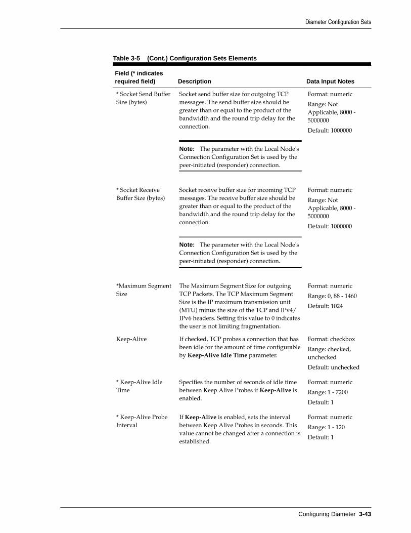
Table 3-5 (Cont.) Configuration Sets Elements
Field (* indicatesrequired field) Description Data Input Notes
* Socket Send BufferSize (bytes)
Socket send buffer size for outgoing TCPmessages. The send buffer size should begreater than or equal to the product of thebandwidth and the round trip delay for theconnection.
Note: The parameter with the Local Node'sConnection Configuration Set is used by thepeer-initiated (responder) connection.
Format: numeric
Range: NotApplicable, 8000 -5000000
Default: 1000000
* Socket ReceiveBuffer Size (bytes)
Socket receive buffer size for incoming TCPmessages. The receive buffer size should begreater than or equal to the product of thebandwidth and the round trip delay for theconnection.
Note: The parameter with the Local Node'sConnection Configuration Set is used by thepeer-initiated (responder) connection.
Format: numeric
Range: NotApplicable, 8000 -5000000
Default: 1000000
*Maximum SegmentSize
The Maximum Segment Size for outgoingTCP Packets. The TCP Maximum SegmentSize is the IP maximum transmission unit(MTU) minus the size of the TCP and IPv4/IPv6 headers. Setting this value to 0 indicatesthe user is not limiting fragmentation.
Format: numeric
Range: 0, 88 - 1460
Default: 1024
Keep-Alive If checked, TCP probes a connection that hasbeen idle for the amount of time configurableby Keep-Alive Idle Time parameter.
Format: checkbox
Range: checked,unchecked
Default: unchecked
* Keep-Alive IdleTime
Specifies the number of seconds of idle timebetween Keep Alive Probes if Keep-Alive isenabled.
Format: numeric
Range: 1 - 7200
Default: 1
* Keep-Alive ProbeInterval
If Keep-Alive is enabled, sets the intervalbetween Keep Alive Probes in seconds. Thisvalue cannot be changed after a connection isestablished.
Format: numeric
Range: 1 - 120
Default: 1
Diameter Configuration Sets
Configuring Diameter 3-43

Table 3-5 (Cont.) Configuration Sets Elements
Field (* indicatesrequired field) Description Data Input Notes
* Keep-AliveMaximum Count
If Keep-Alive is enabled, sets the maximumnumber of Keep Alive Probes TCP sendswithout any response from the remote server,before TCP gives up and aborts theconnection.
Format: numeric
Range: 1 - 16
Default: 9
Radius Options
PendingTransactions PerConnection
The maximum number of Pending Requestswaiting for Response from Peer on thisconnection. If maximum PendingTransactions is reached, then this connectionis not selected for routing until the Pendingtransactions are below this value.
Format: numeric
Range: 1 - 5000
Default: 1000
Prevent duplicatetransactions due toegressretransmissions
This option applies to RADIUS clientconnections only and determines how tohandle a Request being retransmitted to thesame peer as before, but the correspondingtransaction record (that contains thepreviously used source port, RADIUS ID andRequest Authenticator) has expired. If thisoption is selected, and if the correspondingtransaction record has expired, the routingapplication does not forward the Request tothe same peer with a new RADIUS ID, sourceport, and Request Authenticator. An alternatepeer can be selected for routing in this case. Ifthis option is not selected, and thecorresponding transaction record hasexpired, DSR shall select a new source port,RADIUS ID and Request Authenticator,create a new transaction record and forwardthe Request to the peer.
Format: checkbox
Range: checked,unchecked
Default: checked
Diameter Configuration Sets
3-44 Diameter Signaling Router Diameter User's Guide

Table 3-5 (Cont.) Configuration Sets Elements
Field (* indicatesrequired field) Description Data Input Notes
Prevent duplicatetransactions due toingressretransmissions
This option applies to RADIUS serverconnections only and determines how DSRshall processes duplicate requests receivedfrom a client. A request is consideredduplicate if the client retransmits a requestwith the same source IP address, source portnumber, RADIUS ID and RequestAuthenticator. If this option is selected, DSRshall create an ingress transaction record forthe request (with the request's source IPaddress, port, RADIUS ID and RequestAuthenticator) which shall be used to admitonly the first Request into DSR and preventadmitting of duplicate requests, if received,till the transaction record is present. If aResponse has been sent previously to thepeer, it shall be saved in the transactionrecord and shall be forwarded to the client inresponse to duplicate requests. If this optionis not selected, DSR shall not maintainingress transaction records and shall admitall Requests received from the client.
Format: checkbox
Range: checked,unchecked
Default: checked
Cached responseDuration (ms)
This option applies to server connectionsonly. Applicable only if Prevent duplicatetransactions due to ingress retransmissions =Checked. This value specifies the durationfor which a cached response is held in theingress transaction record. This value shouldcover the potential of loss of response andfurther retransmissions by the client.
Format: numeric
Range: 3000 - 100000
Default: 5000
Priority Options
CPL1 MinimumRequest PriorityAllowed
If 16 Priority Admin State is enabled inSystem Options then ConnectionConfiguration Set shall support insertion andupdate of CPL1 Minimum Request PriorityAllowed values in the range of 1-15.
If 16 Priority Admin State is disabled, thenthis field is non-configurable.
Format: checkbox
If 16 Priority AdminState is Enabled:
• Range: 1 - 15• Default: 4If 16 Priority AdminState is Disabed:
• Range: n/a• Default: 1
Diameter Configuration Sets
Configuring Diameter 3-45

Table 3-5 (Cont.) Configuration Sets Elements
Field (* indicatesrequired field) Description Data Input Notes
CPL1 MinimumRequest PriorityAllowed
If 16 Priority Admin State is enabled inSystem Options then ConnectionConfiguration Set shall support insertion andupdate of CPL2 Minimum Request PriorityAllowed values in the range of 2-15.
If 16 Priority Admin State is disabled, thenthis field is non-configurable.
Format: checkbox
If 16 Priority AdminState is Enabled:
• Range: 2 - 15• Default: 8If 16 Priority AdminState is Disabed:
• Range: n/a• Default: 2
CPL1 MinimumRequest PriorityAllowed
If 16 Priority Admin State is enabled inSystem Options then ConnectionConfiguration Set shall support insertion andupdate of CPL3 Minimum Request PriorityAllowed values in the range of 3-16.
If 16 Priority Admin State is disabled, thenthis field is non-configurable.
Format: checkbox
If 16 Priority AdminState is Enabled:
• Range: 3 - 15• Default: 16If 16 Priority AdminState is Disabed:
• Range: n/a• Default: 3
Adding Configuration Sets
Use this task to create new Configuration Sets.
When you add a new Connection Configuration Set all of the fields on each tab areinitially populated with the values from the Default Connection Configuration Set. Fordetails about the fields in the Connection Configuration Set, see Configuration Setselements.
1. Click Diameter > Configuration > Configuration Sets > ConnectionConfiguration Sets.
2. Click Insert.
3. Enter a unique name for the Configuration Set in the Connection ConfigurationSet Name field.
4. Click the SCTP Options tab. Enter the SCTP values in the fields.
5. Click the Diameter Options tab. Enter the Diameter values in the fields.
6. Click the TCP Options tab. Enter the TCP values in the fields.
7. Click the RADIUS Options tab. Enter the RADIUS values in the fields.
8. Click OK, Apply, or Cancel.
Editing Configuration Sets
Use this task to edit existing Configuration Sets.
Diameter Configuration Sets
3-46 Diameter Signaling Router Diameter User's Guide

When the Connection Configuration Sets page opens, the fields are populated with thecurrently configured values.
If the selected Connection Configuration Set is being used by a Local Node, anychanges to the selected Connection Configuration Set do not take effect for Peer-initiated connections until the next time the Peer Node connects to the Local Node.
The Connection Configuration Set Name cannot be edited.
Note: You must disable all Connections that use a particular ConnectionConfiguration Set before you can edit it. See Disabling Connections.
Changes to the Connection Configuration Set take effect after the changes aresaved and the Connections that refer to the changed ConnectionConfiguration Set are set to the Enabled Admin state.
1. Click Diameter > Configuration > Configuration Sets > ConnectionConfiguration Sets.
2. Select the Connection Configuration Set you want to edit.
3. Click Edit.
4. Update the relevant fields.
For information about each field, see Configuration Sets elements.
5. Click OK, Apply, or Cancel.
Deleting Configuration Sets
Use this task to delete Configuration Sets.
A Connection Configuration Set cannot be deleted if it is being used by anyconnections or Local Nodes. Before you perform this task, you must:
1. Disable any connections that use the Connection Configuration Set. See DisablingConnections.
2. Edit those connections to no longer use the Connection Configuration Set. See Editing a Connection.
3. Edit any Local Nodes that use the Connection Configuration Set to no longer doso. See Editing a Local Node.
1. Click Diameter > Configuration > Configuration Sets > ConnectionConfiguration Sets.
2. Select the Connection Configuration Set you want to delete.
3. Click Delete.
A popup window appears to confirm the delete.
4. Click OK or Cancel.
Diameter Configuration Sets
Configuring Diameter 3-47

CEX Configuration SetsA CEX Configuration Set provides a mechanism for assigning up to 10 unique CEXParameters and up to 10 unique supported Vendor IDs to a Local Node or Connection.A default CEX Configuration Set named Default is pre-populated with CEXParameters for the RELAY Application ID (0xFFFFFFFF).
You can perform these tasks on an Active System OAM (SOAM).
Each Local Node refers to a single CEX Configuration Set. The CEX Configuration Setis mandatory for Local Node. Each transport connection can optionally refer to asingle CEX Configuration Set. During CEX message exchange, the CEX ConfigurationSet in the transport connection is used if configured. Otherwise, the CEXConfiguration Set in the Local Node (associated with the transport connection) is used.A Vendor ID can be sent in the Supported-Vendor-ID AVP of a CEX even though theVendor ID is not configured in the Selected Supported Vendor IDs for the CEXConfiguration Set.
The application has a default CEX Configuration Set called Default, which is alwaysavailable. The Default CEX Configuration Set options cannot be modified or deleted.When you create a new CEX Configuration Set the values of the Default CEXConfiguration Set are automatically populated into the new CEX Configuration Set,allowing you to easily create a new CEX Configuration Set that needs to have only afew options adjusted.
On the CEX Configuration Sets page, you can perform the following actions:
• Filter the list of CEX Configuration Sets to display only the desired CEXConfiguration Sets.
• Sort the list in ascending or descending order by clicking the CEX ConfigurationsSet Name column heading. The default order is by CEX Configuration Set Namein ascending ASCII order.
• In the CEX Parameters column,
– Click the + sign to the left of the number of Application IDs to expand the listof Application IDs for a CEX Configuration Set.
– Click the - sign to left of the number of Application IDs to collapse theexpanded list of Application IDs for a CEX Configuration Set.
– Click a blue Application ID in an expanded list to open the Diameter >Configuration > CEX Parameters [Filtered] page for the selected ApplicationID only.
• Click Insert.
On the CEX Configuration Sets [Insert] page, you can add a new CEXConfiguration Set and its values. See Adding a CEX Configuration Set. If themaximum number of CEX Configuration Sets (2000) already exists in the system,then the CEX Configuration Sets [Insert] page does not appear and an errormessage displays.
• Select a CEX Configuration Set Name in the list and click Edit.
On the CEX Configuration Sets [Edit] page, you can edit the selected CEXConfiguration Set. See Editing a CEX Configuration Set. The Default CEXConfiguration Set cannot be edited.
Diameter Configuration Sets
3-48 Diameter Signaling Router Diameter User's Guide

• Select a CEX Configuration Set Name in the list and click Delete to remove theselected CEX Configuration Set.
The Default CEX Configuration Set cannot be deleted. See Deleting a CEXConfiguration Set.
CEX Configuration Set elements
Table 3-6 describes the fields on the CEX Configuration Sets View, Edit, and Insertpages. Data Input Notes only apply to the Insert and Edit pages; the View page isread-only.
Table 3-6 CEX Configuration Sets Elements
Field (* indicatesa required field) Description Data Input Notes
* CEXConfiguration SetName
Unique Name of the CEX ConfigurationSet.
A CEX Configuration Set named Default isalways available.
Case-sensitive string:alphanumeric andunderscore (_); mustcontain at least one alphaand cannot begin with adigit.
Range: 1 - 32 characters
Dynamic Indicates whether or not the CEXConfiguration Set was created dynamically(YES) or statically (NO). NO is assigned forall CEX Configuration Sets via DynamicPeer Discovery.
Format: checkbox (read-only on the CEXConfiguration Set [Edit]page)
Range: checked unchecked
Default: unchecked
* CEX Parameters Available CEX Parameters ApplicationID-"Name"-Type-Vendor IDAll unique configured CEX Parameters,showing Application IDs with ApplicationType, and with Vendor ID if theApplication ID is Vendor-Specific.
Format: list
Range: All configured CEXParameters
Default: none
Selected CEX Parameters ApplicationID-"Name"-Type-Vendor IDCEX Parameters that are selected from theAvailable CEX Parameters list for this CEXConfiguration Set.
Format: list
Range: 10 entries
Default: none
Must Include CEX ParametersApplication ID-"Name"-Type-Vendor IDCEX Parameters selected from the SelectedCEX Parameters list that must be present inthe CEX message exchanged from the Peer.
Format: list
Range: 10 entries
Default: none
SupportedVendor IDs
Available Supported Vendor IDsAll unique Vendor IDs that have beenconfigured in the CEX Parametersconfiguration.
Format: Scrollable list
Range: All configuredVendor IDs
Default: none
Diameter Configuration Sets
Configuring Diameter 3-49

Table 3-6 (Cont.) CEX Configuration Sets Elements
Field (* indicatesa required field) Description Data Input Notes
Selected Supported Vendor IDsVendor IDs selected from the AvailableSupported Vendor IDs list for this CEXConfiguration Set.
Format: list
Range: 10 entries
Default: none
DSR FeatureStatus AVP
If checked, this Vendor specific AVP is sentin CER/CEA messages. It can convey thestatus of various features like NGN-PS toPeer DSR.
Format: checkbox
Range: checked unchecked
Default: unchecked
Adding a CEX Configuration Set
Use this task to create a new CEX Configuration Set.
1. Click Diameter > Configuration > Configuration Sets > CEX Configuration Sets.
2. Click Insert.
3. Enter a unique name for the CEX Configuration Set in the CEX Configuration SetName field.
4. Enter the information for the CEX Parameters in the fields.
• To add CEX Parameters to the Selected CEX Parameters list, select the entry inthe Available CEX Parameters list and click Add below the Available CEXParameters list.
• To add CEX Parameters to the Must Include CEX Parameters list, select theentry in the Selected CEX Parameters list and click Add above the MustInclude CEX Parameters list.
• To remove CEX Parameters from the Selected CEX Parameters list, select theentry in the Selected CEX Parameters list and click Remove below theSelected CEX Parameters list.
• To remove CEX Parameters from the Must Include CEX Parameters list, selectthe entry in the Must Include CEX Parameters list and click Remove above theMust Include CEX Parameters list.
5. Enter the information for the Supported Vendor IDs in the fields.
• To add a Vendor ID to the Selected Supported Vendor IDs list, select the entryin the Available Supported Vendor IDs list and click Add below the AvailableSupported Vendor IDs list.
• To remove a Vendor ID from the Selected Supported Vendor IDs list, selectthe entry in the Selected Supported Vendor IDs list and click Remove abovethe Selected Supported Vendor IDs list.
6. Click OK, Apply, or Cancel.
Diameter Configuration Sets
3-50 Diameter Signaling Router Diameter User's Guide

Editing a CEX Configuration Set
Use this task to edit an existing CEX Configuration Set.
For information about each field, see CEX Configuration Set elements.
Note: You must disable connections that use a particular CEX ConfigurationSet before you can edit the CEX Configuration Set. See Disabling Connections.
1. Click Diameter > Configuration > Configuration Sets > CEX Configuration Sets.
2. Select the CEX Configuration Set that you want to edit.
The Default CEX Configuration Set cannot be changed.
3. Click Edit.
When the page opens, the fields are initially populated with the currentlyconfigured values.
4. Update the relevant fields.
If an entry is attempted that is not valid or is out of range, then an error messageappears.
The CEX Configuration Set Name cannot be changed.
• To add CEX Parameters to the Selected CEX Parameters list, select the entry inthe Available CEX Parameters list and click Add below the Available CEXParameters list.
• To add CEX Parameters to the Must Include CEX Parameters list, select theentry in the Selected CEX Parameters list and click Add above the MustInclude CEX Parameters list.
• To remove CEX Parameters from the Selected CEX Parameters list, select theentry in the Selected CEX Parameters list and click Remove below theSelected CEX Parameters list.
• To remove CEX Parameters from the Must Include CEX Parameters list, selectthe entry in the Must Include CEX Parameters list and click Add above theMust Include CEX Parameters list.
• To add a Vendor ID to the Selected Supported Vendor IDs list, select the entryin the Available Supported Vendor IDs list and click Add below the AvailableSupported Vendor IDs list.
• To remove a Vendor ID from the Selected Supported Vendor IDs list, selectthe entry in the Selected Supported Vendor IDs list and click Remove abovethe Selected Supported Vendor IDs list.
5. Click OK, Apply, or Cancel.
Deleting a CEX Configuration Set
Use this task to delete a CEX Configuration Set.
Diameter Configuration Sets
Configuring Diameter 3-51

A CEX Configuration Set cannot be deleted if it is being used by any connections orLocal Nodes. Before you perform this task, you must:
1. Disable any connections that use the CEX Configuration Set. See DisablingConnections.
2. Edit those connections to no longer use the CEX Configuration Set. See Editing aConnection.
3. Edit any Local Nodes that use the CEX Configuration Set to no longer do so. See Editing a Local Node.
The Default CEX Configuration Set can be edited, but cannot be deleted.
1. Click Diameter > Configuration > Configuration Sets > CEX Configuration Sets.
2. Select one CEX Configuration Set that you want to delete.
3. Click Delete
A popup window appears.
4. Click OK or Cancel.
Capacity Configuration SetsCapacity Configuration Sets provide a mechanism for adjusting a connection toaccount for the network quality of service and Peer Node requirements, and allowmanagement of capacity data for Diameter Peer connections. Capacity ConfigurationSet data consists of reserved Ingress MPS, maximum Ingress MPS, Ingress MPS minoralarm threshold, and Ingress MPS major alarm threshold.
You can perform these tasks on an Active System OAM (SOAM).
The Capacity Configuration Set called Default is always available. The DefaultCapacity Configuration Set options can be modified, but the Default CapacityConfiguration Set cannot be deleted. When you create a new Capacity ConfigurationSet the values of the Default Capacity Configuration Set are automatically populatedinto the new Capacity Configuration Set, allowing you to easily create a new CapacityConfiguration Set that needs to have only a few options adjusted.
Note: The Per Connection Ingress MPS Control feature must be purchasedand enabled before Capacity Configuration Sets can be configured.
On the Capacity Configuration Sets page, you can perform the following actions:
• Filter the list of Capacity Configuration Sets to display only the desired CapacityConfiguration Sets.
• Sort the Capacity Configuration Set entries by clicking the column headings. Bydefault, the entries are sorted by the Capacity Configuration Set column inascending ASCII order.
• Click Insert.
On the Capacity Configuration Sets [Insert] page, you can add a new CapacityConfiguration Sets and its values. See Adding a Capacity Configuration Set.
Diameter Configuration Sets
3-52 Diameter Signaling Router Diameter User's Guide

If the Per Connection Ingress MPS Control feature is not enabled, then theCapacity Configuration Sets [Insert] page does not appear and an error messagedisplays.
If the maximum number of Capacity Configuration Sets (1000) already exists inthe system, then the Capacity Configuration Sets [Insert] page does not appearand an error message displays.
• Select the Name of a Capacity Configuration Set in the list and click Edit.
On the Capacity Configuration Sets [Edit] page, you can edit the selected CapacityConfiguration Set. See Editing a Capacity Configuration Set.
If the Default Capacity Configuration Set is selected and the Per ConnectionIngress MPS Control feature is not enabled, then the Capacity Configuration Sets[Edit] page does not appear and an error message displays.
• Select the Name of a Capacity Configuration Set in the list and click Delete toremove the selected Capacity Configuration Set. See Deleting a CapacityConfiguration Set. The Default Capacity Configuration Set can be edited, but notdeleted.
Connection Capacity Validation
The Connection Capacity Validation function validates and limits the configuration ofDiameter Connections to better ensure that the configuration does not violate theConnection Count or Reserved Ingress MPS capacity limitations of the DA-MP serversthat handle Connections in real time.
The Connection Capacity Validation function is described in Validating DiameterConnection Capacity.
Validation of the Reserved Ingress MPS occurs in response to changes to theconfiguration of Capacity Configuration Sets that increase the Reserved Ingress MPSvalue, including editing the value and replacing the Configuration Set with one thathas a higher value. Such changes reduce the available Reserved Ingress MPS capacityand must be validated before they can be allowed. (Actions that increase capacityrather than reduce it do not require validation.)
An error displays, stating the reason, when the validation determines that performingthe configuration action would cause over-configuration of Reserved Ingress MPS in aDA-MP or Target Set, or that a configuration action cannot be performed for anotherreason such as no MP Profile assigned to the subject DA-MP.
A warning displays when the validation cannot determine whether the configurationaction would cause over-configuration of Reserved Ingress MPS in a DA-MP or TargetSet.
If an error and a warning could apply, then an error displays.
The Diameter > Configuration > Connection Capacity Dashboard page displays thecurrent Connection Count and Reserved Ingress MPS data per DA-MP. The pagefunctions and contents are described in Connection Capacity Dashboard Functions.
Capacity Configuration Set elements
Table 3-7 describes the fields on the Capacity Configuration Sets View, Edit, and Insertpages. Data input notes apply only to the Insert and Edit pages; the View page is read-only.
Diameter Configuration Sets
Configuring Diameter 3-53

Table 3-7 Capacity Configuration Sets Elements
Field (* indicatesfield is required) Description Data Input Notes
* CapacityConfiguration Set
Name of the Capacity Configuration Set. TheName must be unique.
Format: String: case-sensitive;alphanumeric andunderscore (_); mustcontain at least onealpha; cannot beginwith a digit.
Range: 1 - 32characters
* Reserved IngressMPS
The capacity in ingress Diameter messagesper second that are permanently reserved forthe connection. If the default value is set tozero, the connections do not reserve messageprocessing capacity. If the default is a non-zero value, the Reserved Ingress MPSCapacity ranges from 10 to the value of theConnection Engineered Capacity.
If the Reserved Ingress MPS Capacity is anon-zero value that value times the numberof connections using that CapacityConfiguration Set on a given MP server mustnot be allowed to exceed the MP MaximumReserved Ingress MPS.
Format: numeric
Range: 0, 10 - 10000
Default: 0
* Maximum IngressMPS
The maximum rate within Diameter ingressmessages per second that the connection isallowed to process. This field ranges from 100to the value of the MP Maximum ReservedCapacity. It is acceptable for the sum of thecapacity for all connections on an MP serverto exceed the MP Engineered Ingress MPS(and the MP Maximum Reserved IngressMPS).
Format: numeric
Range: 0, 10 - 10000
Default: 10000
* Ingress MPS MinorAlarm Threshold(Percent)
The percentage of the connection's maximumMPS capacity that triggers a minor alarm. Thedefault Capacity Configuration Set has anIngress MPS Capacity Minor AlarmThreshold default value set to 50% of theConnection Configured Maximum IngressMPS with a range from 5% to 100%. Thisalarm threshold must be less than the IngressMPS Capacity Major Alarm Threshold. TheMinor Alarm Abatement threshold is set 5%lower than Minor Alarm Threshold.
Format: numeric
Range: 10 - 99
Default: 50
Diameter Configuration Sets
3-54 Diameter Signaling Router Diameter User's Guide

Table 3-7 (Cont.) Capacity Configuration Sets Elements
Field (* indicatesfield is required) Description Data Input Notes
* Ingress MajorAlarm Threshold(Percent)
The percentage of the connection's maximumMPS capacity that triggers a major alarm. Thedefault Capacity Configuration Set has anIngress MPS Capacity Major AlarmThreshold default value set to 80% of theConnection Configured Maximum IngressMPS with a range from 5% to 100%. Thisalarm threshold must be greater than theIngress MPS Capacity Minor AlarmThreshold. The Major Alarm Abatementthreshold is set 5% lower than Major AlarmThreshold.
Format: numeric
Range: 11 - 100
Default: 80
* Ingress MPS AlarmAbatement Time
The minimum time that connection's ingressmessage rate must remain less than or equalto respective abatement threshold before thealarm clears or its severity reduced fromMajor to Minor.
Format: numeric
Range: 1000 - 5000
Default: 2000
* Convergence Time(ms)
The amount of time (msec) it takes toconverge on a per second rate. If theconvergence time is less than 1000 msec, therate is extrapolated. If the convergence time isgreater than 1000 msec, the rate is averaged.
Format: numeric
Range:
• 250• 500• 1000• 2000• 4000
Default: 1000
Adding a Capacity Configuration Set
Use this task to create a new Capacity Configuration Set. For information about thefields, see Capacity Configuration Set elements.
1. Click Diameter > Configuration > Configuration Sets > Capacity ConfigurationSets.
2. Click Insert.
3. Enter a unique name for the Capacity Configuration Set in the Name field.
4. Enter the Reserved Ingress MPS value in messages/second.
5. Enter the Maximum Ingress MPS value in messages/second.
6. Enter the Ingress MPS Minor Alarm Threshold as the percentage of the MaximumIngress MPS at which a Minor alarm is raised for connections using this CapacityConfiguration Set.
7. Enter the Ingress MPS Major Alarm Threshold as the percentage of the MaximumIngress MPS at which a Major alarm is raised for connections using this CapacityConfiguration Set.
Diameter Configuration Sets
Configuring Diameter 3-55

8. Enter the Ingress MPS Alarm Abatement Time in milliseconds, if a value otherthan the default value is needed.
9. Enter the Convergence Time in milliseconds, if a value other than the default valueis needed
10. Click OK, Apply, or Cancel.
Editing a Capacity Configuration Set
Use this task to edit an existing Capacity Configuration Set.
The changes take effect upon receipt of the next message. Ingress MPS alarms are re-evaluated for all Connections that use the modified Capacity Configuration Set whenthe changes are replicated to the MP servers.
All Connections that use a particular Capacity Configuration Set must be in theDisabled Admin State before the Reserved Ingress MPS value can be changed. Toassistance you in disabling connections refer to Disabling Connections. (The ReservedIngress MPS field is the only field that requires the Connections to be Disabled beforeit can be changed.)
The Per Connection Ingress MPS Control feature must be enabled before the DefaultCapacity Configuration Set can be edited.
The Capacity Configuration Set name cannot be changed.
1. Click Diameter > Configuration > Configuration Sets > Capacity ConfigurationSets.
2. Select the Capacity Configuration Set to be edited.
3. Click Edit.
The Capacity Configuration Sets [Edit] page displays the current values for theselected Capacity Configuration Set.
4. Update the relevant fields.
The fields are described in Capacity Configuration Set elements.
5. Click OK, Apply, or Cancel.
6. Reference Enabling Connections to enable any Connections that were disabledbefore the Capacity Configuration Set was changed.
Deleting a Capacity Configuration Set
Use this task to delete a Capacity Configuration Set.
A Capacity Configuration Set cannot be deleted if it is being used by any Connections.Before you perform this task, you must reference Disabling Connections to disable anyConnections that use the Capacity Configuration Set and reference Editing aConnection to edit each Connection to no longer use the Capacity Configuration Set.
The Default Capacity Configuration Set can be edited, but cannot be deleted.
1. Click Diameter > Configuration > Configuration Sets > Capacity ConfigurationSets.
2. Select the Capacity Configuration Set you want to delete.
Diameter Configuration Sets
3-56 Diameter Signaling Router Diameter User's Guide

3. Click Delete.
A popup window appears to confirm the delete.
4. Click OK or Cancel.
Egress Message Throttling Configuration SetsEgress Message Throttling Configuration Sets provide a mechanism for managingegress message traffic on a Diameter Connection. You can create an Egress MessageThrottling Configuration Set with a maximum allowable Egress Message Rate (EMR)and one to three pairs of EMR Threshold Throttles and Abatement Throttles.
You can perform these tasks on an Active System OAM (SOAM).
When the EMR on a connection exceeds a Threshold Throttle value, the EMRcongestion level for the connection is raised. When the Egress Message Rate on aconnection falls below an Abatement Threshold, the EMR congestion level is lowered.Specifying a Convergence time and Abatement time allows you to control thetransitions between EMR congestion levels. The EMR congestion level, along with theEgress Transport congestion level and the Remote Busy congestion level is used tocontrol traffic on a connection.
The options are described in Egress Message Throttling Configuration Set elements.Each connection can reference a single Egress Message Throttling Configuration Set.
On the Egress Message Throttling Configuration Sets page, you can perform thefollowing actions:
• Filter the list of Egress Message Throttling Configuration Sets to display only thedesired Egress Message Throttling Configuration Sets.
• Sort the list by column contents in ascending or descending order by clicking thecolumn heading. The default order is by Egress Message ThrottlingConfiguration Set Name in ascending ASCII order.
• Click Insert.
On the Egress Message Throttling Configuration Sets [Insert] page, you can add anew Egress Message Throttling Configuration Set and its options. See Adding anEgress Message Throttling Configuration Set.
If the maximum number of Egress Message Throttling Configuration Sets perNetwork Element (50) already exist in the system, then the Egress MessageThrottling Configuration Sets [Insert] page does not appear and an error messagedisplays.
• Select an Egress Message Throttling Configuration Set Name in the list and clickEdit.
On the Egress Message Throttling Configuration Sets [Edit] page, you can edit theselected Egress Message Throttling Configuration Set. See Editing an EgressMessage Throttling Configuration Set.
If at least one connection is in the "Enabled" Admin state that uses the EgressMessage Throttling Configuration Set, then the Egress Message ThrottlingConfiguration Sets [Edit] page does not open.
• Select an Egress Message Throttling Configuration Set Name in the list and clickDelete to remove the selected Egress Message Throttling Configuration Set.
Diameter Configuration Sets
Configuring Diameter 3-57

Egress Message Throttling Configuration Set elements
Table 3-8 describes the fields on the Egress Message Throttling Configuration SetsView, Edit, and Insert pages. Data Input Notes apply only to the Insert and Edit pages;the View page is read-only.
Table 3-8 Egress Message Throttling Configuration Set Elements
Field (* indicatesrequired field) Description Data Input Notes
* Egress MessageThrottlingConfiguration SetName
A name that uniquely identifies the EgressMessage Throttling Configuration Set.
Format: String: case-sensitive;alphanumeric andunderscore (_); mustcontain at least onealpha; cannot beginwith a digit.
Range: 1 - 32characters
* Max EgressMessage Rate
A maximum Egress Message Rate (EMR) on aconnection being throttled
Note: The EMR is calculated every 100msby subtracting the oldest traffic count fromthe newest traffic count, and averaging thedifference over the elapsed time betweenthem.
Format: numeric
Range: 10 - 10000
Default: none
* Throttle ThresholdLevel 1 (%)
Throttle Threshold Level 1. When Thresholdexceeds Level 1, Congestion Level is set to 1
Format: numeric
Range: 2 - 100
Default: 100
* AbatementThreshold Level 1(%)
Abatement Threshold Level 1. WhenThreshold falls below Level 1, CongestionLevel is set to 0.
Format: numeric
Range: 1 - 99
Default: 80
Throttle ThresholdLevel 2 (%)
Throttle Threshold Level 2. When Thresholdexceeds Level 2, Congestion Level is set to 2.
Format: numeric
Range: 4 - 100
Default: none
AbatementThreshold Level 2(%)
Abatement Threshold Level 2. WhenThreshold falls below Level 2, the CongestionLevel is set to 1.
Format: numeric
Range: 3 - 99
Default: none
Throttle ThresholdLevel 3 (%)
Throttle Threshold Level 3. When Thresholdexceeds Level 3, Congestion Level is set to 3.
Format: numeric
Range: 6 -100
Default: none
Diameter Configuration Sets
3-58 Diameter Signaling Router Diameter User's Guide

Table 3-8 (Cont.) Egress Message Throttling Configuration Set Elements
Field (* indicatesrequired field) Description Data Input Notes
AbatementThreshold Level 3(%)
Abatement Threshold Level 3. WhenThreshold falls below Level 3, the CongestionLevel is set to 2.
Format: numeric
Range: 5 - 99
Default: none
* Convergence Time(msec)
The time it takes in milliseconds to convergeon a per second rate. If the convergence timeis less than 1000 milliseconds, the rate isConvergence Time (msec) extrapolated. If theconvergence time is greater than 1000milliseconds, the rate is averaged.
The rate convergence time is the amount oftime it takes for the measured rate toconverge on the actual rate.
Format: numeric
Range:• 250• 500• 1000• 2000• 4000
Default: 250
* Abatement Time(msec)
This value specifies the amount of time that athrottled connection's Egress Request Ratemust remain below an abatement beforeallowing it to abate to a lower CL.
For example, if the following is true:• Max EMR = 1000 messages per second• Abatement Threshold-3 = 80% * 100=>
800 messages per second)• Abatement time = 500 milliseconds• Current Congestion Level = CL3
Then all of the message rate calculationsduring a contiguous 500 msec must be lessthan 800 MPS in order for the congestionlevel to be reduced from CL3 to CL2.
Format: numeric
Range: 200 - 10000
Default: 500
Adding an Egress Message Throttling Configuration Set
Use this task to create a new Egress Message Throttling Configuration Set. For moreinformation about the fields, see Egress Message Throttling Configuration Setelements.
1. Click Diameter > Configuration > Configuration Sets > Egress MessageThrottling Configuration Sets.
2. Click Insert.
3. Enter a unique name for the Configuration Set in the Egress Message ThrottlingConfiguration Set Name field.
4. Enter the maximum Egress Message Rate in the Max EMR field.
5. Enter one to three Throttle Thresholds and Abatement Thresholds as a percentageof the maximum Egress Message Rate.
6. Optionally, enter a Convergence Time and an Abatement Time.
Diameter Configuration Sets
Configuring Diameter 3-59

7. Click OK, Apply, or Cancel.
Editing an Egress Message Throttling Configuration Set
Use this task to edit an existing Egress Message Throttling Configuration Set.
When the Egress Message Throttling Configuration Sets page opens, the fields arepopulated with the currently configured values.
The Egress Message Throttling Configuration Set Name cannot be edited.
1. Click Diameter > Configuration > Configuration Sets > Egress MessageThrottling Configuration Sets.
2. Select the Egress Message Throttling Configuration Set you want to edit.
3. Click Edit.
4. Update the relevant fields.
For information about each field, see Egress Message Throttling Configuration Setelements.
5. Click OK, Apply, or Cancel.
Deleting an Egress Message Throttling Configuration Set
Use this task to delete an Egress Message Throttling Configuration Set.
Note: An Egress Message Throttling Configuration Set cannot be deleted if itis being used by any connections. Before you perform this task, you mustdisable and edit any connections that use the Egress Message ThrottlingConfiguration Set. (See Disabling Connections and Editing a Connection.)
1. Click Diameter > Configuration > Configuration Sets > Egress MessageThrottling Configuration Sets.
2. Select the Egress Message Throttling Configuration Set you want to delete.
3. Click Delete.
A popup window appears to confirm the delete.
4. Click OK or Cancel.
Message Priority Configuration SetsA Message Priority Configuration Set provides a mechanism for controlling howmessage priority is set for a request message arriving on a connection. A MessagePriority Configuration Set contains one or more Message Priority Rules.
You can perform these tasks on an Active System OAM (SOAM).
A Message Priority Rule consists of combination of an Application ID and a CommandCode, and a priority. Incoming messages that match the Application ID and CommandCode are assigned the associated priority.
Message Priority Configuration Sets can be assigned to Connections or Peer Nodes.
Diameter Configuration Sets
3-60 Diameter Signaling Router Diameter User's Guide

The Message Priority Configuration Set fields are described in Message PriorityConfiguration Set elements.
On the Message Priority Configuration Sets page, you can perform the followingactions:
• Filter the list of Message Priority Configuration Sets to display only the desiredMessage Priority Configuration Sets.
• Sort the list by column contents in ascending or descending order by clicking onthe column heading. The default order is by Message Priority Configuration SetName in ascending ASCII order.
• Click the + in the Message Priority Rules field to display the Message PriorityRules associated with a Message Priority Configuration Set.
• Click Insert.
On the Message Priority Configuration Sets [Insert] page, you can add a newMessage Priority Configuration Set and its Message Priority Rules. See Adding aMessage Priority Configuration Set.
If the maximum number of Message Priority Configuration Sets per NetworkElement (20) already exists in the system, then the Message Priority ConfigurationSets [Insert] page does not appear and an error message displays.
• Select a Message Priority Configuration Set Name in the list and click Edit.
On the Message Priority Configuration Sets [Edit] page, you can edit the selectedMessage Priority Configuration Set. See Editing a Message Priority ConfigurationSet.
If at least one connection that uses the Message Priority Configuration Set is in theEnabled Admin state, the Message Priority Configuration Sets [Edit] page doesnot open.
• Select a Message Priority Configuration Set Name in the list and click Delete toremove the selected Message Priority Configuration Set. The Default MessagePriority Configuration Set cannot be deleted.
Message Priority Configuration Set elements
Table 3-9 describes the fields on the Message Priority Configuration Sets View, Edit,and Insert pages. Data Input Notes apply only to the Insert and Edit pages; the Viewpage is read-only.
Table 3-9 Message Priority Configuration Set Elements
Field (* indicates arequired field) Description Data Input Notes
* Message PriorityConfiguration SetName
Unique name of the Message PriorityConfiguration Set.
Format: Case-sensitivestring: alphanumericand underscore (_);must contain at leastone alpha and cannotbegin with a digit.
Range: 1 - 32characters
Diameter Configuration Sets
Configuring Diameter 3-61

Table 3-9 (Cont.) Message Priority Configuration Set Elements
Field (* indicates arequired field) Description Data Input Notes
* Message PriorityRules
The number of Message Priority Rulesdefined in the Message PriorityConfiguration Set.
Application ID The Application ID used to filter incomingDiameter messages.
Format: List
Range: Select from theconfiguredApplication IDs.
Note: An asterisk (*)matches anyApplication ID.
Application Name(view only)
The name of the application associated withthe Application ID.
Command Code The Command Code used to filter incomingDiameter messages.
An ECC is a Command Code that also takesinto account the value of a specific AVP forthat Command Code that gives the "true"command type (for example, CCR-I, CCR-U,and so on).
Note: This list of configured CommandCodes includes Extended Command-Codes(ECC) immediately after their parentCommand-Code.
Format: List
Range: Select from theconfigured CommandCodes.
Note: An asterisk (*)matches anyCommand Code.
Command CodeName (view only)
The name of the command associated withthe Command Code.
Message Priority The message priority assigned to incomingmessages that match the combination ofApplication ID and Command Code.
Format: List
Range: 0 - Max(Maximum NormalRequest Priority asdefined in SystemOptions)
Adding a Message Priority Configuration Set
Use this task to create a new Message Priority Configuration Set. For more informationabout the fields, see Message Priority Configuration Set elements.
1. Click Diameter > Configuration > Configuration Sets > Message PriorityConfiguration Sets.
Diameter Configuration Sets
3-62 Diameter Signaling Router Diameter User's Guide
2. Click Insert.
3. Enter a unique name for the Configuration Set in the Message PriorityConfiguration Set Name field.
4. Select an Application ID, Command Code, and Message Priority for the MessagePriority Rule.
5. Click Add to add more Message Priority Rules to the Message PriorityConfiguration Set.
You can add up to 50 rules per configuration set. Click the X beside the MessagePriority field to clear the values for a Message Priority Rule.
6. Click OK, Apply, or Cancel.
Editing a Message Priority Configuration Set
Use this task to edit an existing Message Priority Configuration Set.
When the Message Priority Configuration Sets page opens, the fields are populatedwith the currently configured values.
The Message Priority Configuration Set Name cannot be edited.
1. Click Diameter > Configuration > Configuration Sets > Message PriorityConfiguration Sets.
2. Select the Message Priority Configuration Set you want to edit.
3. Click Edit.
4. Update the relevant fields.
For information about each field, see Message Priority Configuration Set elements.
5. Click OK, Apply, or Cancel.
Deleting a Message Priority Configuration Set
Use this task to delete a Message Priority Configuration Set.
Note: The Default Message Priority Configuration Set cannot be deleted.
1. Click Diameter > Configuration > Configuration Sets > Message PriorityConfiguration Sets.
2. Select the Message Priority Configuration Set you want to delete.
3. Click Delete.
A popup window appears to confirm the delete.
4. Click OK or Cancel.
Message Copy Configuration SetsA Message Copy Configuration Set provides a mechanism for determining themessages to be copied (Request or Answer), the Result-Code/Experimental Result-
Diameter Configuration Sets
Configuring Diameter 3-63

Code on which the Message Copy is initiated, and number of retries to be made if theMessage Copy attempt to DAS fails. The Message Copy trigger point must specify aMessage Copy Configuration Set when the message is marked for copying.
You can perform these tasks on an Active System OAM (SOAM).
The Message Copy Configuration Set fields are described in Message CopyConfiguration Set elements.
On the Message Copy Configuration Sets page, you can perform the following actions:
• Filter the list of Message Copy Configuration Sets to display only the desiredMessage Copy Configuration Sets.
• Sort the list by column contents in ascending or descending order by clicking thecolumn heading. The default order is by Message Copy Configuration Set Namein ascending ASCII order.
• Click Insert.
On the Message Copy Configuration Sets [Insert] page, you can add a newMessage Copy Configuration Set. See Adding a Message Copy Configuration Set.
If the maximum number of Message Copy Configuration Sets (100) already existsin the system, an error message displays.
• Select a Message Copy Configuration Set Name in the list and click Edit.
On the Message Copy Configuration Sets [Edit] page, you can edit the selectedMessage Copy Configuration Set. See Editing a Message Copy Configuration Set.
If no row is selected, or if more than one row is selected, Edit is disabled.
• Select a Message Copy Configuration Set Name in the list and click Delete toremove the selected Message Copy Configuration Set.
The Default Message Copy Configuration Set can be edited, but cannot be deleted.See Deleting a Message Copy Configuration Set.
Message Copy Configuration Set elements
Table 3-10 describes the fields on the Message Copy Configuration Sets View, Edit, andInsert pages. Data Input Notes apply only to the Insert and Edit pages; the View pageis read-only.
Table 3-10 Message Copy Configuration Set Elements
Field (* indicates arequired field) Description Data Input Notes
* Message CopyConfiguration SetName
Unique name of the Message CopyConfiguration Set.
Case-sensitive string:alphanumeric andunderscore (_); must containat least one alpha and cannotbegin with a digit.
Range: 1 - 32 characters
Diameter Configuration Sets
3-64 Diameter Signaling Router Diameter User's Guide
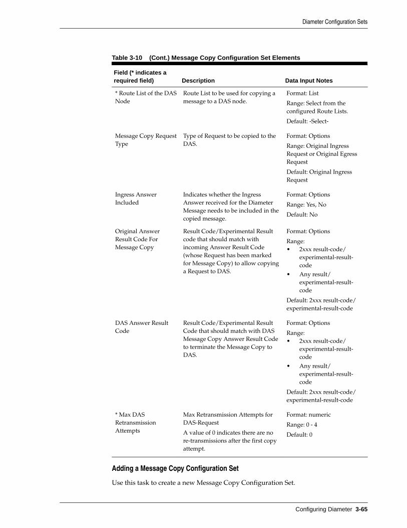
Table 3-10 (Cont.) Message Copy Configuration Set Elements
Field (* indicates arequired field) Description Data Input Notes
* Route List of the DASNode
Route List to be used for copying amessage to a DAS node.
Format: List
Range: Select from theconfigured Route Lists.
Default: -Select-
Message Copy RequestType
Type of Request to be copied to theDAS.
Format: Options
Range: Original IngressRequest or Original EgressRequest
Default: Original IngressRequest
Ingress AnswerIncluded
Indicates whether the IngressAnswer received for the DiameterMessage needs to be included in thecopied message.
Format: Options
Range: Yes, No
Default: No
Original AnswerResult Code ForMessage Copy
Result Code/Experimental Resultcode that should match withincoming Answer Result Code(whose Request has been markedfor Message Copy) to allow copyinga Request to DAS.
Format: Options
Range:• 2xxx result-code/
experimental-result-code
• Any result/experimental-result-code
Default: 2xxx result-code/experimental-result-code
DAS Answer ResultCode
Result Code/Experimental ResultCode that should match with DASMessage Copy Answer Result Codeto terminate the Message Copy toDAS.
Format: Options
Range:• 2xxx result-code/
experimental-result-code
• Any result/experimental-result-code
Default: 2xxx result-code/experimental-result-code
* Max DASRetransmissionAttempts
Max Retransmission Attempts forDAS-Request
A value of 0 indicates there are nore-transmissions after the first copyattempt.
Format: numeric
Range: 0 - 4
Default: 0
Adding a Message Copy Configuration Set
Use this task to create a new Message Copy Configuration Set.
Diameter Configuration Sets
Configuring Diameter 3-65

The fields are described in Message Copy Configuration Set elements.
1. Click Diameter > Configuration > Configuration Sets > Message CopyConfiguration Sets.
2. Click Insert.
If the maximum numbers of Message Copy Configuration Sets (100) allowed in thesystem are already configured, the Message Copy Configuration Sets [Insert] pagedoes not open.
3. Enter a unique name for the Configuration Set in the Message Copy ConfigurationSet Name field.
4. Select or enter the element values.
5. Click OK, Apply, or Cancel.
Editing a Message Copy Configuration Set
Use this task to edit an existing Message Copy Configuration Set.
When the Message Copy Configuration Sets page opens, the fields are populated withthe currently configured values.
The Message Copy Configuration Set Name cannot be edited.
The fields are described in Message Copy Configuration Set elements.
1. Click Diameter > Configuration > Configuration Sets > Message CopyConfiguration Sets.
2. Select the Message Copy Configuration Set you want to edit.
3. Click Edit.
4. Update the relevant fields.
5. Click OK, Apply, or Cancel.
Deleting a Message Copy Configuration Set
Use this task to delete a Message Copy Configuration Set.
The Default Message Copy Configuration Set can be edited, but cannot be deleted.
1. Click Diameter > Configuration > Configuration Sets > Message CopyConfiguration Sets.
2. Select the Message Copy Configuration Set you want to delete.
3. Click Delete.
A popup window appears to confirm the delete.
4. Click OK or Cancel.
Rate Limiting Configuration SetsRate Limiting Configuration Sets provide the mechanism to enter data needed byEgress Throttle Groups (on the SOAM GUI) and Egress Throttle Lists (on the NOAM
Diameter Configuration Sets
3-66 Diameter Signaling Router Diameter User's Guide

GUI) to perform egress throttling by egress message rate. For details about the NOAMfunctionality, see Rate Limiting Configuration Sets on the NOAM.
You can perform these tasks on an Active System OAM (SOAM).
An Egress Throttling Group is always associated with a Rate Limiting ConfigurationSet, which provides the following data for performing Egress Message Rate Throttling:
• Maximum Message Rate
• Onset and Abatement Thresholds:
– Percentages of the maximums
– Used with Message Priority to determine which requests to throttle
• Convergence time, which allows you to control the sensitivity of request trafficbursts on an ETG.
• Abatement time
Rate Limiting can be enabled on the SOAM Main Menu: Diameter > Maintenance >Egress Throttle Groups page.
For NOAM functionality, you must change the Egress Throttling Control Scope of theEgress Control Group to ETL and enable Egress Message Rate Throttle on the EgressThrottle Group before Egress Message Rate Throttling can be started on EgressThrottle Lists.
The Rate Limiting Configuration Set fields are described in Rate LimitingConfiguration Sets elements.
On the Rate Limiting Configuration Sets page, you can perform the following actions:
• Filter the list of Rate Limiting Configuration Sets to display only the desired RateLimiting Configuration Sets.
• Sort the list by column contents in ascending or descending order by clicking thecolumn heading. The default order is by Rate Limiting Configuration Set Namein ascending ASCII order.
• Click Insert.
On the Rate Limiting Configuration Sets [Insert] page, you can add a new RateLimiting Configuration Set. See Adding a Rate Limiting Configuration Set.
If the maximum number of Rate Limiting Configuration Sets already exists in thesystem, an error message displays.
• Select a Rate Limiting Configuration Set Name in the list and click Edit.
On the Rate Limiting Configuration Sets [Edit] page, you can edit the selectedRate Limiting Configuration Set. See Editing a Rate Limiting Configuration Set.
If no row is selected, or if more than one row is selected, Edit is disabled.
• Select a Rate Limiting Configuration Set Name in the list and click Delete toremove the selected Rate Limiting Configuration Set.
The Default Rate Limiting Configuration Set can be edited, but cannot be deleted.See Deleting a Rate Limiting Configuration Set.
Diameter Configuration Sets
Configuring Diameter 3-67

Rate Limiting Configuration Sets elements
Table 3-11 describes the fields on the Rate Limiting Configuration Sets View, Edit, andInsert pages. Data input notes apply only to the Insert and Edit pages; the View page isread-only.
Note: This GUI page is available from the SOAM and NOAM menu.
Table 3-11 Rate Limiting Configuration Sets Elements
Field (* indicates a requiredfield) Description Data Input Notes
Rate Limiting ConfigurationSet Name
Unique name of the RateLimiting Configuration Set.
Case-sensitive string:alphanumeric andunderscore (_); must containat least one alpha and cannotbegin with a digit.
Range: 1 - 32 characters
* Maximum Egress RequestRate
The maximum allowedEgress Request Rate sharedby associated members.
Format: numeric
Range: 100 - 250000
Default: 6000
* Onset Threshold Level 1 (%) When Egress Request Rateexceeds this percentage ofmaximum Egress RequestRate, the Congestion Level isset to 1. Onset ThresholdLevel 1 is ignored if ETGMode is Limit.
Format: numeric
Range: 2 - 100
Default: 60
* Abatement Threshold Level1 (%)
When Egress Request Ratefalls below this percentage ofmaximum Egress RequestRate, the Congestion Level isset to 0. AbatementThreshold Level 1 is ignoredif ETG Mode is Limit.
Format: numeric
Range: 1 - 100
Default: 55
Onset Threshold Level 2 (%) When Egress Request Rateexceeds this percentage ofmaximum Egress RequestRate, the Congestion Level isset to 2. Onset ThresholdLevel 2 is ignored if ETGMode is Limit.
Format: numeric
Range: 4 - 100
Default: none
Diameter Configuration Sets
3-68 Diameter Signaling Router Diameter User's Guide

Table 3-11 (Cont.) Rate Limiting Configuration Sets Elements
Field (* indicates a requiredfield) Description Data Input Notes
Abatement Threshold Level 2(%)
When Egress Request Ratefalls below this percentage ofmaximum Egress RequestRate, the Congestion Level isset to 1. AbatementThreshold Level 2 is ignoredif ETG Mode is Limit.
Format: numeric
Range: 3 - 100
Default: none
Onset Threshold Level 3 (%) When Egress Request Rateexceeds this percentage ofmaximum Egress RequestRate, the Congestion Level isset to 3. Onset ThresholdLevel 3 is ignored if ETGMode is Limit.
Format: numeric
Range: 6 - 100
Default: none
Abatement Threshold Level 3(%)
When Egress Request Ratefalls below this percentage ofmaximum Egress RequestRate, the Congestion Level isset to 2. AbatementThreshold Level 3 is ignoredif ETG Mode is Limit.
Format: numeric
Range: 5 - 100
Default: none
* Convergence Time (msec) The time it takes inmilliseconds to converge on aper second rate. If theconvergence time is less than1000 milliseconds, the rate isextrapolated. If theconvergence time is greaterthan 1000 milliseconds, therate is averaged.
The rate convergence time isthe amount of time it takesfor the measured rate toconverge on the actual rate.
Format: List
Range: 250, 500, 1000, 2000,4000
Default: 250
* Abatement Time (msec) The amount of time inmilliseconds that the EgressRequest Rate must remainbelow an abatementthreshold before theCongestion Level is lowered.
Format: numeric
Range: 50 - 10000
Default: 50
Adding a Rate Limiting Configuration Set
Use this task to create a new Rate Limiting Configuration Set.
Diameter Configuration Sets
Configuring Diameter 3-69

Note: This GUI page is available from the SOAM and NOAM menu.
The fields are described in Rate Limiting Configuration Sets elements.
1. Click Diameter > Configuration > Configuration Sets > Rate LimitingConfiguration Sets on the SOAM or Diameter > Configuration > Egress ThrottleList > Rate Limiting Configuration Sets on the NOAM.
2. Click Insert.
3. Enter a unique name for the Rate Limiting Configuration Set in the Rate LimitingConfiguration Set Name field.
4. Select or enter the element values.
5. Click OK, Apply, or Cancel.
Editing a Rate Limiting Configuration Set
Use this task to edit an existing Rate Limiting Configuration Set.
Note: This GUI page is available from the SOAM and NOAM menu.
When the Rate Limiting Configuration Sets page opens, the fields are populated withthe currently configured values.
The Rate LimitingConfiguration Set Name cannot be edited.
The fields are described in Rate Limiting Configuration Sets elements.
1. Click Diameter > Configuration > Configuration Sets > Rate LimitingConfiguration Sets on the SOAM or Diameter > Configuration > Egress ThrottleList > -Rate Limiting Configuration Sets on the NOAM.
2. Select the Rate Limiting Configuration Set you want to edit.
3. Click Edit.
4. Update the relevant fields.
5. Click:
• OK to save the changes and return to the Rate Limiting Configuration Setspage.
• Apply to save the changes and remain on this page.
• Cancel to return to the Rate Limiting Configuration Sets page without savingany changes.
If OK or Apply is clicked and any of the following conditions exist, then an errormessage appears:
• The selected Rate Limiting Configuration Set no longer exists; it has beendeleted by another user.
• Any field is empty (no value was entered) .
Diameter Configuration Sets
3-70 Diameter Signaling Router Diameter User's Guide

• The value in any field is not valid or is out of range.
Deleting a Rate Limiting Configuration Set
Use this task to delete a Rate Limiting Configuration Set.
Note: This GUI page is available from the SOAM and NOAM menu.
The Default Rate Limiting Configuration Set can be edited, but cannot be deleted.
1. Click Diameter > Configuration > Configuration Sets > Rate LimitingConfigurations Sets on the SOAM or Diameter > Configuration -> EgressThrottle List > -Rate Limiting Configuration Sets on the NOAM.
2. Select the Rate Limiting Configuration Set you want to delete.
3. Click Delete.
A popup window appears to confirm the delete.
4. Click OK or Cancel.
Pending Transaction Limiting Configuration SetsPending Transaction Limiting Configuration Sets configuration provides themechanism to enter configuration data needed by Egress Throttle Groups to determinewhen to start throttling for pending transactions. For details about the NOAMfunctionality, see Pending Transaction Limiting Configuration Sets on the NOAM.
An ETG is always associated with a Pending Transaction Limiting Configuration Setthat provides the following data for performing Egress Message Rate Throttling basedon pending transactions:
• Maximum pending transactions
• Onset and Abatement Thresholds:
– Percentages of the maximums
– Used with Message Priority to determine which requests to throttle
• Abatement time
You must enable Pending Transaction Limiting before Egress Pending TransactionLimiting can be started on Egress Throttle Groups.
The Pending Transaction Limiting Configuration Sets fields are described in PendingTransaction Limiting Configuration Sets elements.
On the Pending Transaction Limiting Configuration Sets page, you can perform thefollowing actions:
• Filter the list of Pending Transaction Limiting Configuration Sets to display onlythe desired Pending Transaction Limiting Configuration Sets.
• Sort the list by column contents in ascending or descending order by clicking thecolumn heading. The default order is by Pending Transaction LimitingConfiguration Sets in ascending ASCII order.
Diameter Configuration Sets
Configuring Diameter 3-71
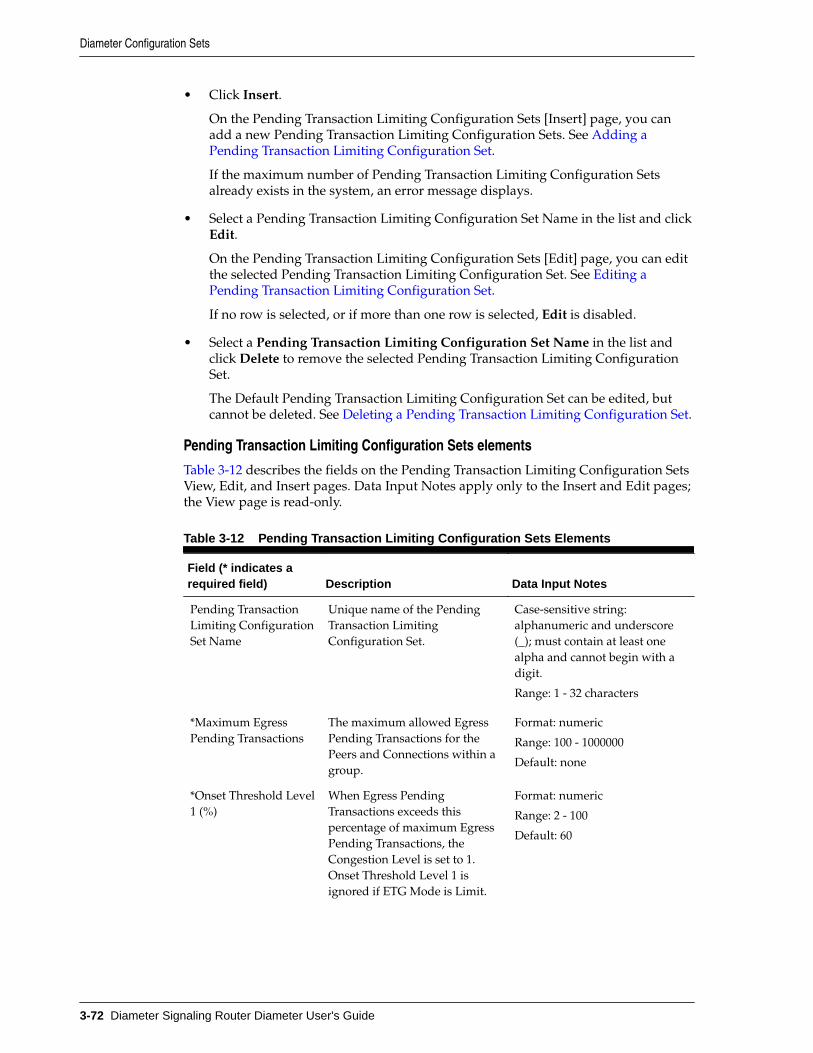
• Click Insert.
On the Pending Transaction Limiting Configuration Sets [Insert] page, you canadd a new Pending Transaction Limiting Configuration Sets. See Adding aPending Transaction Limiting Configuration Set.
If the maximum number of Pending Transaction Limiting Configuration Setsalready exists in the system, an error message displays.
• Select a Pending Transaction Limiting Configuration Set Name in the list and clickEdit.
On the Pending Transaction Limiting Configuration Sets [Edit] page, you can editthe selected Pending Transaction Limiting Configuration Set. See Editing aPending Transaction Limiting Configuration Set.
If no row is selected, or if more than one row is selected, Edit is disabled.
• Select a Pending Transaction Limiting Configuration Set Name in the list andclick Delete to remove the selected Pending Transaction Limiting ConfigurationSet.
The Default Pending Transaction Limiting Configuration Set can be edited, butcannot be deleted. See Deleting a Pending Transaction Limiting Configuration Set.
Pending Transaction Limiting Configuration Sets elements
Table 3-12 describes the fields on the Pending Transaction Limiting Configuration SetsView, Edit, and Insert pages. Data Input Notes apply only to the Insert and Edit pages;the View page is read-only.
Table 3-12 Pending Transaction Limiting Configuration Sets Elements
Field (* indicates arequired field) Description Data Input Notes
Pending TransactionLimiting ConfigurationSet Name
Unique name of the PendingTransaction LimitingConfiguration Set.
Case-sensitive string:alphanumeric and underscore(_); must contain at least onealpha and cannot begin with adigit.
Range: 1 - 32 characters
*Maximum EgressPending Transactions
The maximum allowed EgressPending Transactions for thePeers and Connections within agroup.
Format: numeric
Range: 100 - 1000000
Default: none
*Onset Threshold Level1 (%)
When Egress PendingTransactions exceeds thispercentage of maximum EgressPending Transactions, theCongestion Level is set to 1.Onset Threshold Level 1 isignored if ETG Mode is Limit.
Format: numeric
Range: 2 - 100
Default: 60
Diameter Configuration Sets
3-72 Diameter Signaling Router Diameter User's Guide

Table 3-12 (Cont.) Pending Transaction Limiting Configuration Sets Elements
Field (* indicates arequired field) Description Data Input Notes
*Abatement ThresholdLevel 1 (%)
When Egress PendingTransactions falls below thispercentage of maximum EgressPending Transactions, theCongestion Level is set to 0.Abatement Threshold Level 1 isignored if ETG Mode is Limit.
Format: numeric
Range: 1 - 100
Default: 55
Onset Threshold Level2 (%)
When Egress PendingTransactions exceeds thispercentage of maximum EgressPending Transactions, theCongestion Level is set to 2.Onset Threshold Level 2 isignored if ETG Mode is Limit.
Format: numeric
Range: 4 - 100
Default: none
Abatement ThresholdLevel 2 (%)
When Egress PendingTransactions falls below thispercentage of maximum EgressPending Transactions, theCongestion Level is set to 1.Abatement Threshold Level 2 isignored if ETG Mode is Limit.
Format: numeric
Range: 3 - 100
Default: none
Onset Threshold Level3 (%)
When Egress PendingTransactions exceeds thispercentage of maximum EgressPending Transactions, theCongestion Level is set to 3.Onset Threshold Level 3 isignored if ETG Mode is Limit.
Format: numeric
Range: 6 - 100
Default: none
Abatement ThresholdLevel 3 (%)
When Egress PendingTransactions falls below thispercentage of maximum EgressPending Transactions, theCongestion Level is set to 2.Abatement Threshold Level 3 isignored if ETG Mode is Limit.
Format: numeric
Range: 5 - 100
Default: none
*Abatement Time(msec)
The amount of time inmilliseconds that EgressPending Transactions mustremain below an abatementthreshold before the CongestionLevel is lowered.
Format: numeric
Range: 50 - 10000
Default: 50
Adding a Pending Transaction Limiting Configuration Set
Use this task to create a new Pending Transaction Limiting Configuration Sets.
The fields are described in Pending Transaction Limiting Configuration Sets elements.
Diameter Configuration Sets
Configuring Diameter 3-73
1. Click Diameter > Configuration > Configuration Sets > Pending TransactionLimiting Configuration Sets on the SOAM or Diameter > Configuration > EgressThrottle List > Pending Transaction Limiting Configuration Sets on the NOAM.
2. Click Insert.
3. Enter a unique name for the Pending Transaction Limiting Configuration Set in thePending Transaction Limiting Configuration Set Name field.
4. Select or enter the element values.
5. Click OK, Apply, or Cancel.
Editing a Pending Transaction Limiting Configuration Set
Use this task to edit an existing Pending Transaction Limiting Configuration Set.
When the Pending Transaction Limiting Configuration Sets page opens, the fields arepopulated with the currently configured values.
The Pending Transaction Limiting Configuration Set Name cannot be edited.
The fields are described in Pending Transaction Limiting Configuration Sets elements.
1. Click Diameter > Configuration > Configuration Sets > Pending TransactionLimiting Configuration Sets on the SOAM or Diameter > Configuration > EgressThrottle List > Pending Transaction Limiting Configuration Sets on the NOAM.
2. Select the Pending Transaction Limiting Configuration Set you want to edit.
3. Click Edit.
4. Update the relevant fields.
5. Click OK, Apply, or Cancel.
Deleting a Pending Transaction Limiting Configuration Set
Use this task to delete a Pending Transaction Limiting Configuration Set.
The Default Pending Transaction Limiting Configuration Set can be edited, but cannotbe deleted.
1. Click Diameter > Configuration > Configuration Sets > Pending TransactionLimiting Configuration Sets on the SOAM or Diameter > Configuration > EgressThrottle List > Pending Transaction Limiting Configuration Sets on the NOAM.
2. Select the Pending Transaction Limiting Configuration Set you want to delete.
3. Click Delete.
A popup window appears to confirm the delete.
4. Click OK or Cancel.
Transaction Configuration SetsA Transaction Configuration Set provides a mechanism to assign routing andtransaction attributes (ART, PRT, PAT, and ROS) to Diameter request message based onApplication ID and (Extended) Command Code.
You can perform these tasks on an Active System OAM (SOAM).
Diameter Configuration Sets
3-74 Diameter Signaling Router Diameter User's Guide

Configuration of Transaction Configuration Sets (TCS) that contain one or moreTransaction Configuration Rules is supported. These Transaction Configuration Rulesallow the assignment of routing and transaction attributes, for example RoutingOption Set (ROS), Pending Answer Timer (PAT), Application Route Table (ART) andPeer Route Table (PRT) to Diameter messages based on Application ID and (Extended)Command Code.
The Transaction Configuration Set fields are described in Transaction ConfigurationSets elements.
On the Transaction Configuration Sets page, you can perform the following actions:
• Filter the list of Transaction Configuration Sets to display only the desiredTransaction Configuration Sets.
• Sort the list by column contents in ascending or descending order by clicking thecolumn heading. The default order is by Transaction Configuration Set Name inascending ASCII order.
• Click Insert.
On the Transaction Configuration Sets [Insert] page, you can add a newTransaction Configuration Set. See Adding a Transaction Configuration Set.
If the maximum number of Transaction Configuration Sets already exists in thesystem, an error message displays.
• Select a Transaction Configuration Set Name in the list and click Edit.
On the Transaction Configuration Sets [Edit] page, you can edit the selectedTransaction Configuration Set. See Editing a Transaction Configuration Set.
If no row is selected, the Edit is disabled.
• Select a Transaction Configuration Set Name in list and click Delete to remove theselected Transaction Configuration Set.
The Default Transaction Configuration Set can be edited, but cannot be deleted.See Deleting a Transaction Configuration Set.
Transaction Configuration Sets elements
Table 3-13 describes the fields on the Transaction Configuration Sets View, Edit, andInsert pages. Data input notes apply only to the Insert and Edit pages; the View page isread-only.
Note: If Application ID with an optional Command Code is selected, one ofthe other four routing attributes (ROS, PAT, ART, PRT) is mandatory.
Table 3-13 includes references to topics where you can define the attributes associatedwith the selected Transaction Configuration Sets.
Diameter Configuration Sets
Configuring Diameter 3-75

Table 3-13 Transaction Configuration Sets Elements
Field (* indicates arequired field) Description Data Input Notes
* TransactionConfiguration SetName
Unique name of the TransactionConfiguration Set.
Case-sensitive string:alphanumeric and underscore(_); must contain at least onealpha and cannot begin with adigit.
Range: 1 - 32 characters
TransactionConfiguration Rules
The rules associated with theTransaction Configuration SetName
Format: Expandable orcollapsible list of rulesassociated with the selectedTransaction Configuration SetName
Application ID The Application ID in theDiameter message. In the viewonly screen, the Application IDhyperlinks to the Diameter >Configuration > Application Ids(Filtered)
Note: For more informationabout the configuration ofApplication Ids, see UsingApplication IDs to IdentifyDiameter Applications.
Format: List
Range: List of configuredApplication IDs
Default: not applicable
Command Code The Command code in theDiameter message. In the viewonly screen, the Application IDhyperlinks to the Diameter >Configuration > CommandsCodes (Filtered)
Note: For more informationabout the configuration ofCommands Codes, see DiameterCommand Codes.
Format: List
Range: List of configuredCommand Codes
Default: not applicable
Diameter Configuration Sets
3-76 Diameter Signaling Router Diameter User's Guide

Table 3-13 (Cont.) Transaction Configuration Sets Elements
Field (* indicates arequired field) Description Data Input Notes
Routing Option Set The Routing Options Setassociated with the ApplicationID and Command Code (ifspecified). In the view onlyscreen, the Application IDhyperlinks to the Diameter >Configuration > Routing OptionSets (Filtered)
Note: For more informationabout the configuration ofRouting Option Sets, see Diameter Routing Option Sets.
Format: List
Range: List of configuredRouting Option Sets
Default: not applicable
Pending AnswerTimer
The Pending Answer Timeassociated with Application IDand Command Code (ifspecified). In the view onlyscreen, the Application IDhyperlinks to the Diameter >Configuration > PendingAnswer Timers (Filtered)
Note: For more informationabout the configuration ofPending Answer Timers, see Diameter Pending AnswerTimers.
Format: List
Range: List of configuredPending Answer Timers
Default: not applicable
Application RouteTable
The Application Route Tableassociated with Application IDand Command Code (ifspecified). In the view onlyscreen, the Application IDhyperlinks to the Diameter >Configuration > ApplicationRoute Tables (Filtered)
Note: For more informationabout the configuration ofApplication Route Tables, see Diameter Application RouteTables.
Format: List
Range: List of configuredApplication Route Tables
Default: not applicable
Diameter Configuration Sets
Configuring Diameter 3-77

Table 3-13 (Cont.) Transaction Configuration Sets Elements
Field (* indicates arequired field) Description Data Input Notes
Peer Route Table The Peer Route Table associatedwith Application ID andCommand Code (if specified). Inthe view only screen, theApplication ID hyperlinks to theDiameter > Configuration > PeerRoute Tables (Filtered)
Note: For more informationabout the configuration of PeerRoute Tables, see Diameter PeerRoute Tables.
Format: List
Range: List of configured PeerRoute Tables
Default: not applicable
Adding a Transaction Configuration Set
Use this task to create a new Transaction Configuration Set.
The fields are described in Transaction Configuration Sets elements.
1. Click Diameter > Configuration > Configuration Sets >TransactionConfiguration Sets.
2. Click Insert.
3. Enter a unique name for the Configuration Set in the Transaction ConfigurationSet Name field.
4. Select or enter the element values.
5. Click OK, Apply, or Cancel.
Editing a Transaction Configuration Set
Use this task to edit an existing Transaction Configuration Set.
When the Transaction Configuration Sets page opens, the fields are populated with thecurrently configured values.
The Transaction Configuration Set Name cannot be edited.
The fields are described in Transaction Configuration Sets elements.
1. Click Diameter > Configuration > Configuration Sets > TransactionConfiguration Sets.
2. Select the Transaction Configuration Set you want to edit.
3. Click Edit.
4. Update the relevant fields.
Diameter Configuration Sets
3-78 Diameter Signaling Router Diameter User's Guide

5. Click OK, Apply, or Cancel.
Deleting a Transaction Configuration Set
Use this task to delete a Transaction Configuration Set.
The Default Transaction Configuration Set can be edited, but cannot be deleted.
1. Click Diameter > Configuration > Configuration Sets > TransactionConfiguration Sets.
2. Select the Transaction Configuration Set you want to delete.
3. Click Delete.
A popup window appears to confirm the delete.
4. Click OK or Cancel.
Traffic Throttle Point Configuration SetsA TTP Configuration Set defines a set of configuration attributes for a TTP, and can beassigned to one or more TTPs.
You can modify any of the TTP Configuration Sets attributes while the TTP is enabledfor service (Throttling Admin State is Enabled).
You can perform these tasks on an Active System OAM (SOAM).
You can perform the following actions for Traffic Throttle Point Configuration Sets:
• Filter the list of Traffic Throttle Point Configuration Sets to display only thedesired Traffic Throttle Point Configuration Sets.
• Sort the list by column contents in ascending or descending order by clicking thecolumn heading. The default order is by Traffic Throttle Point Configuration SetName in ascending ASCII order.
• Click Insert.
On the Traffic Throttle Point Configuration Sets [Insert] page, you can add a newTraffic Throttle Point Configuration Set. See Adding Traffic Throttle PointConfiguration Sets.
If the maximum number of Traffic Throttle Point Configuration Sets already existsin the system, an error message displays.
• Select a Traffic Throttle Point Configuration Set Name in the list. Click Edit todisplay the Traffic Throttle Point Configuration Sets [Edit] page and edit theselected Traffic Throttle Point Configuration Set.
See Editing Traffic Throttle Point Configuration Sets.
If no Name is selected, Edit is disabled.
• Select a Traffic Throttle Point Configuration Set Name in the list and click Deleteto remove the selected Traffic Throttle Point Configuration Set.
The default Traffic Throttle Point Configuration Set can be edited, but cannot bedeleted. See Deleting Traffic Throttle Point Configuration Sets.
Diameter Configuration Sets
Configuring Diameter 3-79

Traffic Throttle Point Configuration Sets elementsTable 3-14 describes the fields on the Traffic Throttle Point Configuration Sets View,Edit, and Insert pages. Data input notes apply only to the Insert and Edit pages; theView page is read-only.
Table 3-14 Traffic Throttle Point Configuration Sets Elements
Field (* indicates arequired field) Description Data Input Notes
* Name A name of the TTP ConfigurationSet.
Case-sensitive string:alphanumeric and underscore(_); must contain at least onealpha and cannot begin with adigit.
Range: 1 - 32 characters
* AbatementRecovery Rate(Percent)
Defines the rate of reduction in lossapplied to a TTP when the loss timeperiod has expired.
Format: numeric
Range: 1 - 100
Default: 5
Override MessagePriority Threshold
This attribute is only accessed duringrouting and changes to its value donot impact any pending transactions.When a pending transaction isrerouted or when a new transactionis processed, the new attribute valueis used.
When this parameter is set, messageswhose priority is greater than orequal to this value are immune fromdiversion if the TTP's OTR is belowits Maximum ETR attribute value.
Note: If the TTP's OTR is greater orequal to the TTP's Maximum ETR,the only transaction exempt fromdiversion are NGN-PS transactionswith priority=4 (and none of the TTPpriority override transactions areexempt from TTP diversion). If theTTP's OTR is less than the TTP'sMaximum ETR and you haveenabled TTP priority override, thenall TTP priority override transactionsare also exempt from TTP diversion(as well as NGN-PS transactions).
Format: numeric
Range: 1, 2
Default: none
Diameter Configuration Sets
3-80 Diameter Signaling Router Diameter User's Guide

Table 3-14 (Cont.) Traffic Throttle Point Configuration Sets Elements
Field (* indicates arequired field) Description Data Input Notes
Default ReductionPercentage
The default reduction percentage fora DOIC overload report if the valueis not specified.
Format: numeric
Range: 0 - 100
Default: 0
* Default ValidityDuration
The default validity duration for aDOIC overload report if the value isnot specified.
Format: numeric
Range: 0 - 86400
Default: 30
* Rate ConvergenceTime
The time it takes in milliseconds toconverge on a per second rate. If theconvergence time is less than 1000milliseconds, the rate is extrapolated.If the convergence time is greaterthan 1000 milliseconds, the rate isaveraged.
The rate convergence time is theamount of time it takes for themeasured rate to converge on theactual rate.
Format: numeric
Range: 250, 500, 1000, 2000
Default: 1000
Adding Traffic Throttle Point Configuration Sets
Use this task to create a new Traffic Throttle Point Configuration Set.
The fields are described in Traffic Throttle Point Configuration Sets elements.
1. Click Diameter > Configuration > Configuration Sets > Traffic Throttle PointConfiguration Sets.
2. Click Insert.
3. Enter a unique name for the TTP Configuration Set in the Name field.
4. Select or enter the element values.
5. Click OK, Apply, or Cancel.
Editing Traffic Throttle Point Configuration Sets
Use this task to edit an existing Traffic Throttle Point Configuration Set.
When the Traffic Throttle Point Configuration Sets page opens, the fields arepopulated with the currently configured values.
The Traffic Throttle Point Configuration Set Name cannot be edited.
The fields are described in Traffic Throttle Point Configuration Sets elements.
1. Click Diameter > Configuration > Configuration Sets > Traffic Throttle PointConfiguration Sets.
Diameter Configuration Sets
Configuring Diameter 3-81

2. Select the Traffic Throttle Point Configuration Set you want to edit.
3. Click Edit.
4. Update the relevant fields.
5. Click OK, Apply, or Cancel.
Deleting Traffic Throttle Point Configuration Sets
Use this task to delete Traffic Throttle Point Configuration Sets.
The default Traffic Throttle Point Configuration Set can be edited, but cannot bedeleted.
1. Click Diameter > Configuration > Configuration Sets > Traffic Throttle PointConfiguration Sets.
2. Select the Traffic Throttle Point Configuration Set you want to delete.
3. Click Delete.
A popup window appears to confirm the delete.
4. Click OK or Cancel.
Diameter Local NodesA Local Node is a local Diameter node that is specified with a realm and an FQDN.When used in conjunction with RADIUS connections, it represents either a RADIUSclient or a RADIUS server.
You can perform these tasks on an Active System OAM (SOAM).
The Local Node identifies:
• Local Node Name
• Realm
• SCTP Listen Port Number
• TCP Listen Port Number
• DTLS/SCTP Listen Port
• TLS/TCP Listen Port
• Radius UDP Server Ports
• Enable Radius UDP Client Ports
• Radius Client UDP Port Range Start
• Radius Client UDP Port Range End
• Verification Mode
• Certificate Type
• Certificate Name
Diameter Local Nodes
3-82 Diameter Signaling Router Diameter User's Guide

• Connection Configuration Set
• CEX Configuration Set
• A list of IP addresses available for establishing Diameter transport connections
After it is configured, a Local Node can be assigned to connections for use in Diameterrouting. Select one of the following connection transport configurations:
• SCTP
• DLTS over SCTP
• TCP
• TLS over TCP
For each connection you can select, TCP, SCTP, TLS/TCP or DTLS/SCTP as thesecurity mechanism used to establish that connection to the peer. DTLS is availableonly for SCTP connections and TLS is available only for TCP connections.
Note: If you select TLS/DTLS, avoid using IPSec. Although IPsec is stillsupported, you must ensure that a connection does not implement both IPSecand TLS/DTLS, as this would have significant performance impacts.
TLS and DTLS are application layer security protocols that run over TCP and SCTPtransport. TLS/DTLS provides tighter encryption via handshake mechanisms, andsupports up to 1000 certificates for a node and across the network. TLS/DTLS requirespre-configured certificates/keys that are used during the handshake procedure aftertransport level connection is established, but before diameter capabilities areexchanged with the peers. The Local Node configuration uses imported certificates/keys and verification mode. If the handshake fails, the connection is not allowed to beestablished depending on the verification mode associated with the connection.
Note the following restrictions:
• If an attempt is made to edit a Connection and the specified Transport Protocol isDTLS, if the DTLS feature is not activated on the SOAM being used to edit theConnection, an error code is generated and the Connection information is not beupdated in the configuration.
• Upon startup, the value of DtlsFeatureEnabled flag defined in DpiOption table isread, and depending on its value, the application does or does not send AUTHExtensions in SCTP_INIT and SCTP_INIT_ACK message while establishing SCTPor DTLS connections.
Note: Any edits to DtlsFeatureEnabled flag defined in DpiOption table afterstartup do not take effect until the next diameter process restart.
• Client-side or server-side authentication for a TLS/DTLS connection is supportedautomatically when this is required by peer server or peer client.
• When TLS/DTLS is selected for a diameter-initiated connection, the TLS/DTLSparameters defined by the operator in the local node are applied. The applicationbehavior is related to the local node Verification Mode selection.
Diameter Local Nodes
Configuring Diameter 3-83

• When TLS/DTLS is selected for a connection and TLS/DTLS cannot beestablished either due to a failed key exchange or because the peer does notsupport TLS/DTLS, the connection is not allowed.
• TLS/DTLS connections initiated by a Diameter peer are responded to. If TLS/DTLS cannot be established due to a failed key exchange, the connection is notallowed. A valid certificate and matching key are required, but you can set theVerification Mode to None to override this behavior.
• You cannot change the security mechanism selected for a connection while theconnection is active.
On the Diameter > Configuration > Local Nodes page, you can perform the followingactions:
• Filter the list of Local Nodes to display only the desired Local Nodes.
• Sort the list by a column in ascending or descending order by clicking the columnheading (except IP Addresses). The default order is by Local Node Name inascending ASCII order.
• Click a field entry for a Local Node.
• Click Insert.
On the Diameter > Configuration > Local Nodes [Insert] page, you can add anew Local Node.
The Diameter > Configuration > Local Nodes [Insert] page does not open if anyof the following conditions exist:
– The maximum number of Local Nodes (32) has already been configured.
– There is no Signaling VIP Address available in the signaling NetworkElement (NE) that can be added to the Local Node.
• Select a Local Node in the list and click Edit.
On the Diameter > Configuration > Local Nodes [Edit] page, you can edit theselected Local Node.
• Select a Local Node in the list and click Delete. You can delete the selected LocalNode.
Diameter Local Node configuration elementsTable 3-15 describes the fields on the Local Nodes View, Insert, and Edit pages. DataInput Notes only apply to the Insert and Edit pages; the View page is read-only.
Diameter Local Nodes
3-84 Diameter Signaling Router Diameter User's Guide

Table 3-15 Local Node Configuration Elements
Field (* indicatesrequired field) Description Data Input Notes
* Local NodeName
Unique name of the Local Node. Format: string, case-sensitive;alphanumeric and underscore(_); cannot start with a digitand must contain at least onealpha
Range: 1 - 32 characters
Default: none
* Realm Realm of the Local Node; defines theadministrative domain with which theuser maintains an account relationship.
Format: string consisting of alist of labels separated by dots.A label can contain letters,digits, dash (-), andunderscore (_). A label mustbegin with a letter, digit, orunderscore, and must endwith a letter or digit.Underscore can be used onlyas the first character.
Range: Realm - up to 255characters; label - up to 63characters
Default: none
* FQDN Unique Fully Qualified Domain Name;specifies exact location in the treehierarchy of the DNS.
Format: a case-insensitivestring consisting of a list oflabels separated by dots. Alabel must contain letters,digits, dash (-), andunderscore (_). A label mustbegin with a letter orunderscore, and must endwith a letter or digit.Underscore can be used onlyas the first character.
Range: FQDN - up to 255characters; label - up to 63characters
Default: none
Diameter Local Nodes
Configuring Diameter 3-85

Table 3-15 (Cont.) Local Node Configuration Elements
Field (* indicatesrequired field) Description Data Input Notes
SCTP Listen Port SCTP listen port number for the LocalNode.
This SCTP Listen Port cannot be thesame as a Local Initiate Port of aConnection.
Initiator port ranges are divided intouser-assigned and DCL-assigned sub-ranges.
Note: DCL-assigned sub-ranges isimplemented via OAM, and isrestricted to connections only.
DCL (Diameter Transport Layer) is thesoftware layer of the stack whichimplements diameter transportconnections.
Format: numeric
Range: 1024 - 49151
Default: 3868
TCP Listen Port TCP listen port number for the LocalNode.
This TCP Listen Port cannot be thesame as a Local Initiate Port of aConnection.
Initiator port ranges are divided intouser-assigned and DCL-assigned sub-ranges.
Note: DCL-assigned sub-ranges isimplemented via OAM, and isrestricted to connections only.
DCL (Diameter Transport Layer) is thesoftware layer of the stack whichimplements diameter transportconnections.
Format: numeric
Range: 1024 - 49151
Default: 3868
Diameter Local Nodes
3-86 Diameter Signaling Router Diameter User's Guide

Table 3-15 (Cont.) Local Node Configuration Elements
Field (* indicatesrequired field) Description Data Input Notes
DTLS/SCTPListen Port
The DTLS/SCTP listen port number forthe Local Node.
Datagram Transport Layer Securityallows datagram based applications tocommunicate in a way that is designedto prevent eavesdropping, tampering,or message forgery. The DTLS protocolis based on the stream-orientedTransport Layer Security (TLS)protocol.
Format: numeric
Range: 1024 - 49151
Default: 5658
TLS/TCP ListenPort
The TLS/TCP listen port number forthe Local Node.
TLS (Transport Layer Security) is anapplication layer security protocol thatruns over TCP transport.
Format: numeric
Range: 1024 - 49151
Default: 5658
RADIUS UDPServer Ports
UDP Port numbers used by RADIUSclients when sending RADIUSmessages to the DSR. If no UDP port isspecified here, this Local Node does notreceive requests from RADIUS clients.
Format: numeric
Range: 1024 - 49151
Default: none
Enable RADIUSUDP Client Ports
When checked, this Local Node cansend RADIUS request messages to aRADIUS server using one of the UDPports specified in the RADIUS ClientUDP Port Range.
Format: checkbox
Range: none
Default: unchecked
RADIUS ClientUDP Port RangeStart
The lowest UDP port number that canbe used to send RADIUS requestmessages to a remote RADIUS server.
Note: If this Local Node does notshare any IP address with any otherLocal Node, this Local Node can usethe default client port range start of2000. However, if this Local Nodeshares any IP addresses with one ormore other Local Nodes, this LocalNode can only use the default portrange start of 2000 if none of the otherLocal Nodes (that share an IP with thisLocal Node) overlaps the port rangespecified for this Local Node.
Format: numeric
Range: 1024 - 49151
Default: 2000
Diameter Local Nodes
Configuring Diameter 3-87
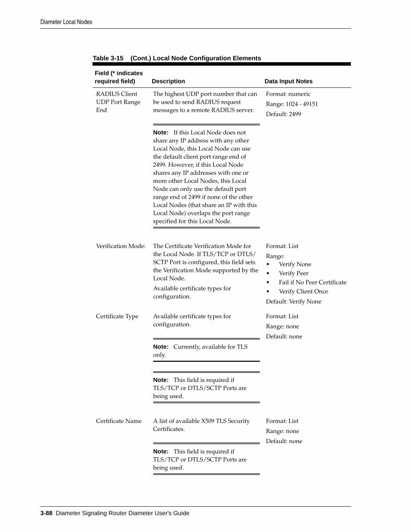
Table 3-15 (Cont.) Local Node Configuration Elements
Field (* indicatesrequired field) Description Data Input Notes
RADIUS ClientUDP Port RangeEnd
The highest UDP port number that canbe used to send RADIUS requestmessages to a remote RADIUS server.
Note: If this Local Node does notshare any IP address with any otherLocal Node, this Local Node can usethe default client port range end of2499. However, if this Local Nodeshares any IP addresses with one ormore other Local Nodes, this LocalNode can only use the default portrange end of 2499 if none of the otherLocal Nodes (that share an IP with thisLocal Node) overlaps the port rangespecified for this Local Node.
Format: numeric
Range: 1024 - 49151
Default: 2499
Verification Mode: The Certificate Verification Mode forthe Local Node. If TLS/TCP or DTLS/SCTP Port is configured, this field setsthe Verification Mode supported by theLocal Node.
Available certificate types forconfiguration.
Format: List
Range:• Verify None• Verify Peer• Fail if No Peer Certificate• Verify Client Once
Default: Verify None
Certificate Type Available certificate types forconfiguration.
Note: Currently, available for TLSonly.
Note: This field is required ifTLS/TCP or DTLS/SCTP Ports arebeing used.
Format: List
Range: none
Default: none
Certificate Name A list of available X509 TLS SecurityCertificates.
Note: This field is required ifTLS/TCP or DTLS/SCTP Ports arebeing used.
Format: List
Range: none
Default: none
Diameter Local Nodes
3-88 Diameter Signaling Router Diameter User's Guide

Table 3-15 (Cont.) Local Node Configuration Elements
Field (* indicatesrequired field) Description Data Input Notes
* ConnectionConfiguration Set
Connection Configuration Set for theLocal Node.
Format: List
Range: configured ConnectionConfiguration Sets, DefaultConnection Configuration Set
* CEXConfiguration Set
CEX Configuration Set associated withthe Local Node.
The entries in the CEX ConfigurationSet field create links to the Diameter >Configuration > CEX ConfigurationSets [Filtered] page, which shows onlythe selected entry.
The CEX Configuration Set field for theLocal Node is used if the CEXConfiguration Set is not associated withthe Connection.
Format: List
Range: configured CEXConfiguration Sets, DefaultCEX Configuration Set.
Diameter Local Nodes
Configuring Diameter 3-89

Table 3-15 (Cont.) Local Node Configuration Elements
Field (* indicatesrequired field) Description Data Input Notes
* IP Addresses IP address, or addresses, available forestablishing Diameter transportConnections to the Local Node. Youmust assign at least one IP Address,and can assign up to 128 IP addresses,to a Local Node. Up to 32 IP addressescan be IPFE Target Set Addresses.
If fewer than four XSI interfaces areconfigured and SCTP transport isselected, then the number of IPAddresses selected must be the same asthe number of XSI interfaces.
On the Local Nodes GUI pages, each IPaddress has appended to it:• For VIP addresses, the string VIP
VIPs are present only in 1+1Active/Standby configurations
• For static IP addresses, the MPServer Hostname of the DA-MPthat owns the IP addressStatic IP addresses are presentonly in Multi-Active N+0configurations
• For TSAs, the name of the TargetSet that the IP address corresponds(for example, TSA# and TSA#-a foralternate IP Addresses where # isthe Target Set numberTSAs can be present in either, butdo not have to be present at all.
If a TSA is selected and InitiatorConnection Support is enabled,configuration of a listener to residewithin responder port range isenforced. If a TSA is selected andInitiator Connection Support is notenabled and the provided port isout of range (1024 - 49151):– If existing local node [Edit],
the operation is allowed witha warning
– If new local node [Insert], theoperation is denied with anerror
Note: See Adding a Connectionfor more information.
Format: Lists
Range: 1 - 128 entries
Default: none
Diameter Local Nodes
3-90 Diameter Signaling Router Diameter User's Guide

Table 3-15 (Cont.) Local Node Configuration Elements
Field (* indicatesrequired field) Description Data Input Notes
If a combination of TSAs areselected (one from a target set thathas Initiator Connection Supportenabled, one that does not),enforce configuration of thelistener to reside within responderport range is enforced. An errormessage is generated if theconnection is configuredincorrectly.
For the IPFE to differentiate betweenresponder and initiator connections, itchecks the destination port of theincoming packet. The IPFE processesthe incoming packet according to rulesassociated with the range into whichthe destination port falls. To provideunambiguous destination ports,diameter routing provides non-overlapping port ranges.
Adding a Local Node
Use this task to create a new Local Node.
1. Click Diameter > Configuration > Local Nodes.
2. Click Insert.
3. Enter a unique name for the Local Node in the Local Node Name field.
4. Enter the Realm for the Local Node in the field.
5. Enter an FQDN in the field.
6. Enter an SCTP Listen Port number in the field.
This is the port used by connections that use this Local Node to listen for SCTPrequest messages. The default 3868 is the well-known IANA port for Diametertraffic.
7. Enter a TCP Listen Port number in the field.
This is the port used by connections that use this Local Node to listen for TCPrequest messages. The default 3868 is the well-known IANA port for Diametertraffic.
8. Enter a DTLS/SCTP Listen Port number in the field.
This is the port used by connections that use this Local Node to listen for DTLS/SCTP request messages. The default 5658 is the well-known IANA port forDiameter traffic.
Diameter Local Nodes
Configuring Diameter 3-91

9. Enter a TLS/TCP Listen Port number in the field.
This is the port used by connections that use this Local Node to listen for TLS/TCPrequest messages. The default 5658 is the well-known IANA port for Diametertraffic.
10. Make selections for RADIUS UDP ports and ranges.
11. Select a Verification Mode from the list.
This is establishes the Certificate Verification Mode. If either TLS/TCP or DTLS/SCTP Port is configured, this sets the Verification Mode supported by the LocalNode. The default Verify None.
12. Select a Certificate Type from the list.
This establishes the Certificate Types available for configuration. This is mandatoryif either of the TLS/TCP or DTLS/SCTP ports are being used.
13. Select a Certificate Name from the list of available X509 TLS Security Certificates.
This is mandatory if either of the TLS/TCP or DTLS/SCTP ports are being used.
14. Select a Connection Configuration Set from the list. If you have not addedadditional Connection Configuration Sets, only the Default ConnectionConfiguration Set is available.
15. Select a CEX Configuration Set for the Local Node from the list.
If you have not added additional CEX Configuration Sets, only the Default CEXConfiguration Set is available.
16. Select from 1 to 128 IP addresses from the IP Addresses list. See Diameter LocalNode configuration elements for details about this element.
17. Click OK, Apply, or Cancel.
For the RADIUS Client UDP Port Range End value, if this Local Node does notshare any IP address with any other Local Node, this Local Node can use thedefault client port range end of 2499. However, if this Local Node shares any IPaddress(es) with one or more other Local Nodes, this Local Node can only use thedefault port range end of 2499 if none of the other Local Nodes (that share an IPwith this Local Node) overlaps the port range specified for this Local Node. For theRADIUS Client UDP Port Range Start value, if this Local Node does not share anyIP address with any other Local Node, this Local Node can use the default clientport range start of 2000. However, if this Local Node shares any IP address(es) withone or more other Local Nodes, this Local Node can only use the default port rangestart of 2000 if none of the other Local Nodes (that share an IP with this LocalNode) overlaps the port range specified for this Local Node.
Editing a Local Node
Use this task to edit a Local Node.
When the Diameter > Configuration > Local Nodes [Edit] page opens, the fields areinitially populated with the current values for the selected Local Node.
Configuration considerations:
Diameter Local Nodes
3-92 Diameter Signaling Router Diameter User's Guide

• The Local Node Name cannot be changed.
• The following fields cannot be edited if there is at least one associated Enabledconnection:
– Realm
– FQDN
– SCTP Listen Port (and the Transport Protocol is SCTP)
– TCP Listen Port (and the Transport Protocol is TCP)
– DTLS/SCTP Listen Port
– TLS/TCP Listen Port
– RADIUS UDP Server Ports
– RADIUS UDP Client Ports
– Enable RADIUS UDP Port Range Start
– Enable RADIUS UDP Port Range End
– Verification Mode
– Certificate Type
– Certificate Name
– Connection Configuration Set
– CEX Configuration Set
• IP Address (cannot be removed if there is an Enabled connection, but a new IPAddress can be added)
1. Click Diameter > Configuration > Local Nodes.
2. Select the Local Node you want to edit, then click Edit.
3. Update the relevant fields.
For more information about each field, see Diameter Local Node configurationelements.
The value for an entry in a list can be removed by selecting --Select-- in the list, orselecting the X at the end of the list (if an X is available).
4. Click OK, Apply, or Cancel.
Deleting a Local Node
Use this task to delete a Local Node.
Note: A Local Node cannot be deleted if it is being used by any connections.Before you perform this task, disable and delete any connections that use theLocal Node.
Diameter Local Nodes
Configuring Diameter 3-93

1. Click Diameter > Configuration > Local Nodes.
2. Select the Local Node you want to delete.
3. Click Delete.
A pop up window appears to confirm the delete.
4. Click OK or Cancel.
Diameter Peer NodesA Peer Node can represent either a Diameter Node or a RADIUS Node. Whenrepresenting a Diameter Node, a Peer Node is an external Diameter client, server, oragent with which the application establishes direct transport connections. Qhwnrepresenting a RADIUS Node, a Peer Node may be a single system or a cluster ofsystems and might have one or more transport connections.
You can perform these tasks on an Active System OAM (SOAM).
A Transaction ID is a unique end-to-end transaction ID created by DRL for eachunique transaction received from an ingress Peer Node. This value is created whenPeer Node routing commences and is stored in the Pending Transaction Record (PTR)for the lifetime of this end-to-end transaction. Its value does not change when theRequest message is rerouted. You can apply transaction configuration sets that allowindependent grouping of transaction configuration rules for varying use case needs.
If a Route List to route a Request message via a PRT search cannot be located and themessage is not addressed to a Peer Node (via the Destination-Host AVP), an attempt ismade to perform Implicit Realm Routing. Using the Destination-Realm AVP andApplication-Id in the Request message, a matching entry in the system-wide RealmRoute Table is sought. This identifies a Route List to use for routing the message. If amatch is found, the Route List assigned to the (Realm, Application-Id) is used forrouting the message. If a match is not found, transaction routing is abandoned.
Diameter Request messages can only be forwarded to Peer Nodes that support theApplication to which the message is addressed (identified by the Application-ID fieldin the message). The List of Common Application IDs is acquired for elements thatcontain that connection (for example, Peer Nodes, Route Groups, and Route Lists).When a Connection is no longer a candidate for routing Request messages, the List ofCommon Application IDs for each Route List, Route Group, and Peer Node whichcontain this Connection are updated to reflect the potential loss of Application IDssupported by that Connection.
After it is configured, a Peer Node can be:
• Assigned to connections for use in Diameter routing
• Assigned to Route Groups that manage the distribution of traffic to and amongPeer Nodes
On the Diameter > Configuration > Peer Nodes page, you can perform the followingactions:
• Filter the list of Peer Nodes to display only the desired Peer Nodes.
• Sort the list by a column in ascending or descending order by clicking the columnheading (except IP Addresses). The default order is by Peer Node Name inascending ASCII order.
Diameter Peer Nodes
3-94 Diameter Signaling Router Diameter User's Guide

• Click an entry that is shown in blue in a column to open the Diameter >Configuration > <component> [Filtered] page and display that entry only.
• Click Insert.
On the Diameter > Configuration > Peer Nodes [Insert] page, you can add a newPeer Node.
The Diameter > Configuration > Peer Nodes [Insert] does not open if themaximum number of Peer Nodes per Network Element (16000) already exists inthe system.
• Select a Peer Node in the list and click Edit.
On the Diameter > Configuration > Peer Notes [Edit] page, you can edit theselected Peer Node.
• Select a Peer Node in the list and click Delete. You can delete the selected PeerNode.
Redirect Notification Processing and Message Redirection
An egress Peer Node, acting as a Redirect Agent, can send an answer with a redirectnotification. The result code in the answer can indicate either diameter redirect ordiameter realm redirect. Upon receiving the redirect notification, the configurationdictates how to reroute the request (Redirected Request). If redirect notification isenabled, the redirected request can be started from ART or PRT.
Redirect notifications are processed as follows:
• Redirect notifications with no Redirect-Host-Usage AVP are processed.
• Redirect notifications with Redirect-Host-Usage equal to do not cache areprocessed.
• Redirect notifications with Redirect-Host-Usage not equal to do not cache areforwarded to the downstream peer.
The following original transaction attributes are carried with the redirectedtransaction:
• Copy of the original Request message received
• Connection ID associated with the ingress Request message
• Information about whether the transaction was initiated by a Peer Node or anapplication
• Routing information received from the application
• The number of times the Request message has been forwarded/rerouted and theRedirected Peer List
• The Message Copy related flag, route list ID, or config set ID
• TTR Event
Diameter Peer Node configuration elementsTable 3-16 describes the fields on the Peer Node's Insert and Edit pages. Data inputnotes apply only to the Insert and Edit pages.
Diameter Peer Nodes
Configuring Diameter 3-95

Note: Any request for a list of peer nodes does not include any dynamically-created peer node instances.
When you select peer node from a peer route group, you can specify to pass over peernodes that have too high of a DOIC loss rate.
Table 3-16 Peer Node Configuration Elements
Field (* indicatesrequired field) Description Data Input Notes
* Peer Node Name Unique name of the peer node. Format: text
Range: valid name
AAA Protocol Specifies the AAA protocol for this peernode, which defines the peer node asdiameter or RADIUS.
Format: list
Range: diameter orRADIUS
Default: NA
* Realm Realm of the peer node. Format: text
Range: valid realmrequired
* FQDN Unique Fully Qualified Domain Name(FQDN); specifies exact location in thetree hierarchy of the DNS.
Format: text
Range: valid FQDNrequired
SCTP Listen Port SCTP listen port number for the peernode.
If the SCTP connection mode is set asResponder Only, the port is notconsidered a listen port and the value3868 displays in the field.
Format: numeric
Range: 1024 - 65535
Default: 3868
TCP Listen Port TCP listen port number for the peer node.
If the TCP connection mode is set asResponder Only, the port is notconsidered a listen port and the value3868 displays in the field.
Format: numeric
Range: 1024 - 65535
Default: 3868
Diameter Peer Nodes
3-96 Diameter Signaling Router Diameter User's Guide

Table 3-16 (Cont.) Peer Node Configuration Elements
Field (* indicatesrequired field) Description Data Input Notes
DTLS/SCTP ListenPort
The DTLS/SCTP listen port number forthe peer node.
If the DTLS/SCTP connection mode is setas Responder Only, the port is notconsidered a listen port and the value5658 displays in the field.
Datagram Transport Layer Security(DTLS) allows datagram basedapplications to communicate in a way thatis designed to prevent eavesdropping,tampering, or message forgery. The DTLSprotocol is based on the stream-orientedTransport Layer Security (TLS) protocol.
Format: numeric
Range: 1024 - 65535
Default: 5658
TLS/TCP ListenPort
The TLS/TCP listen port number for thepeer node.
If the TLS/TCP connection mode is set asResponder Only, the port is notconsidered a listen port and the value5658 displays in the field.
Transport Layer Security (TLS) is anapplication layer security protocol thatrun over TCP transport.
Format: numeric
Range: 1024 - 65535
Default: 5658
RADIUS UDPServer Ports
UDP ports that serve (server port) as adestination port for messages from DA-MP to this peer node (representing aRADIUS server). When the peer node isrepresenting a RADIUS server, thisrepresents the UDP ports that can serve asa destination port for requests forwardedby DSR to the RADIUS server. A RADIUSclient connection associated with the peernode must select one of these ports as adestination port during connectionconfiguration to have DSR forwardrequests to the RADIUS server at theselected destination port.
Format: numeric
Range: 1024 - 49151
Default: NA
Diameter Peer Nodes
Configuring Diameter 3-97

Table 3-16 (Cont.) Peer Node Configuration Elements
Field (* indicatesrequired field) Description Data Input Notes
IP Addresses IP address, or addresses, available forestablishing diameter transportconnections to the peer node.
View - Each peer node entry displays a +sign and the number of IP addressesassigned to that peer node. Click the +sign to display the IP addresses; the + signchanges to a - sign. Click the - sign todisplay the number again.
[Insert] and [Edit] - The field contains anAdd button that can be clicked up to 127times to create 128 text boxes for IPaddresses. Each entry is numbered toindicate the number of IP addresses thathave been added.
Format: numeric
Range: up to 128 valid IPaddresses
Default: NA
Dynamic Indicates whether or not the peer nodewas created dynamically (YES) orstatically (NO). NO is assigned for allpeer node instances, except for thosecreated via dynamic peer discovery. If youattempt to edit a peer node whosedynamic attribute is yes, several of theGUI page attributes are rendered read-only.
Note: This element does not display onthe Peer Nodes [Insert] page.
Format: checkbox (read-only on the Peer Nodes[Edit] page)
Range: checked,unchecked
Default: unchecked
Alternate ImplicitRoute
Route list to use for routing messages tothis peer node if all peer routing rules andimplicit peer routes are unavailable.
Each entry in the Alternate ImplicitRoute column on the view page is a linkto the Diameter > Configuration > RouteList [Filtered] page for the selected entryonly.
Format: List
Range: configured routeLists
Default: none
Replace Dest Realm If checked, the destination realm AVP ofoutgoing messages is overwritten withthis peer node realm.
Format: checkbox
Range: checked,unchecked
Default: unchecked
Diameter Peer Nodes
3-98 Diameter Signaling Router Diameter User's Guide

Table 3-16 (Cont.) Peer Node Configuration Elements
Field (* indicatesrequired field) Description Data Input Notes
Replace Dest Host If checked, the destination host AVP ofoutgoing messages is overwritten withthis peer node FQDN.
Format: checkbox
Range: checked,unchecked
Default: unchecked
Topology HidingStatus
If enabled, diameter topology hiding isapplicable to this peer node.
See Diameter Topology Hiding.
Format: list
Range: disabled, enabled
Default: disabled
* MinimumConnectionCapacity
The minimum number of connections thatmust be available to this peer in order forit to be available. Otherwise, the peer isdegraded if fewer than the minimumnumber of connections are available, orunavailable if no connections areavailable.
Format: numeric
Range: 1-64
Default: 1
* MaximumAlternate RoutingAttempts
The maximum number of times that arequest can be rerouted to this peer beforethe next eligible peer is selected.
Format: numeric
Range: 1-4
Default: 4
Alternate RoutingOn ConnectionFailure
Indicates whether to perform alternaterouting on alternate connections to thesame peer before selecting the nexteligible peer of a peer route group, when aconnection failure occurs.
Format: options
Range: same peer,different peer
Default: different peer
Alternate RoutingOn AnswerTimeout
Indicates whether to perform alternaterouting on the same connection or onalternate connections to the same peerbefore selecting the next eligible peer of apeer route group, when an answertimeout occurs.
Format: options
Range: same peer,different peer, sameconnection
Default: different peer
TransactionConfiguration Set
A configuration managed object thatallows independent grouping oftransaction configuration rules forvarying use case needs.
For example, an ingress peer node canoptionally use this configuration forrouting and transaction parameters(ART/PRT/ROS/PAT) selection. Up to100 of such containers are supported forgrouping transaction configuration rules.
Format: list
Range: default, configuredtransaction configurationsets
Default: not selected
Diameter Peer Nodes
Configuring Diameter 3-99

Table 3-16 (Cont.) Peer Node Configuration Elements
Field (* indicatesrequired field) Description Data Input Notes
Alternate RoutingOn Answer ResultCode
Indicates whether to perform alternaterouting on alternate connections to thesame peer before selecting the nexteligible peer of a peer route group, when areroute on answer result code occurs.
Format: options
Range: same peer,different peer
Default: different peer
Application RouteTable
The application route table associatedwith this peer node.
If application route table is set to is NotSelected, search default transactionconfiguration set and apply longest/strongest match. Use ART associated withbest match, if any is found.
Format: list
Range: default, configuredapplication route tables
Default: not selected
Peer Route Table The peer route table associated with thepeer node.
If peer route table is set to Not Selected,search default transaction configurationset and apply longest/strongest match.Use PRT associated with best match, ifany is found.
Format: list
Range: default, configuredpeer route Tables
Default: not selected
Ingress RoutingOption Set
The routing option set associated with thisingress peer node.
If Ingress routing option set is set to NotSelected, search default TransactionConfiguration Set and apply longest/strongest match. Use ROS associated withbest match, if any is found.
Format: list
Range: default, configuredrouting Option Sets
Default: not selected
Egress PendingAnswer Timer
The Pending Answer Timer associatedwith the egress peer node.
If egress pending answer timer is set toNot Selected, search default TransactionConfiguration Set and apply longest/strongest match. Use PAT associated withbest match, if any is found.
Format: list
Range: default, configuredPending Answer Timers
Default: not selected
Message PrioritySetting
Defines the source of Message Priority fora request message arriving on aconnection associated with the peer node.
The message priority setting for theconnection takes precedence over themessage priority setting for the peer node.
Format: options
Range: none, read fromrequest message, userconfigured
Default: none
Diameter Peer Nodes
3-100 Diameter Signaling Router Diameter User's Guide

Table 3-16 (Cont.) Peer Node Configuration Elements
Field (* indicatesrequired field) Description Data Input Notes
Message PriorityConfiguration Set
The Message Priority Configuration setused if User Configured is selected for themessage priority setting
Format: list
Range: default, configuredmessage priorityconfiguration sets
Default: -select-
Peer Node GroupName
A group of peer nodes that share commoncharacteristics and attributes. This groupis used by IPFE for peer node groupaware connection distribution.
Format: unique string,case-sensitive;alphanumeric andunderscore (_); cannotstart with a digit and mustcontain at least one alpha
Range: 1 - 32 characters
AVP Removal List The AVP removal list associated with thispeer node.
See Diameter AVPRemoval Lists.
Answer On AnyConnection
Defines whether an Ingress Answermessage on any connection from a PeerNode is supported or not.
If enabled for a Peer Node, then DSRprocesses the Ingress Diameter Answermessage received on any connection fromthe same upstream Peer to which theEgress Diameter Request message wassent.
If disabled for a Peer Node, then DSRabandons the Diameter Answer messagereceived on a different connection fromthe one on which the request was sent tothe peer.
Format: checkbox
Range: checked,unchecked
Default: unchecked
Traffic ThrottlePoint
The number of TTPs. See Diameter TrafficThrottle Points.
Adding a Peer Node
Use this task to create a new Peer Node.
1. Click Diameter > Configuration > Peer Nodes.
2. Click Insert.
3. Enter a unique name for the Peer Node in the Peer Node Name field.
4. Make a selection for AAA Protocol.
5. Enter the Realm.
6. Enter a FQDN.
Diameter Peer Nodes
Configuring Diameter 3-101
7. Enter a SCTP Listen Port number.
If the SCTP connection mode is configured as Initiator or Initiator & Responder,then the port listens to SCTP connections. If the SCTP connection mode is set asResponder Only, the port is not considered a listen port and the value 3868displays in the field.
8. Enter a TCP Listen Port number.
If the TCP connection mode is configured as Initiator or Initiator & Responder,then the port listens to TCP connections. If the TCP connection mode is set asResponder Only, the port is not considered a listen port and the value 3868displays in the field.
9. Enter a DTLS/SCTP Listen Port number.
If the DTLS/SCTP connection mode is configured as Initiator or Initiator &Responder, then the port listens to DTLS/SCTP connections. If the DTLS/SCTPconnection mode is set as Responder Only, the port is not considered a listen portand the value 5658 displays in the field.
10. Enter a TLS/TCP Listen Port number.
If the TLS/TCP connection mode is configured as Initiator or Initiator &Responder, then the port listens to TLS/TCP connections. If the TLS/TCPconnection mode is set as Responder Only, the port is not considered a listen portand the value 5658 displays in the field.
11. Enter a RADIUS UDP Server Port.
12. Enter an IP Addresses.
An IP address is optional if a Primary DNS Server IP Address is configured. See Diameter DNS Options.
To add the first IP Address, enter the IP address in the text box.
To add another IP Address, click Add and enter the IP Address in the new text box.See Table 3-16 for limitations on the number of IP addresses you can add.
13. Select a Alternate Implicit Route from the list.
This field is optional. This Route List is used for routing if a message does notmatch any of the configured Peer Routing Rules and implicit routes are exhausted.
14. To overwrite the Destination Realm of outgoing messages to the peer with the PeerRealm, click the Replace Dest Realm checkbox (a check mark appears in the box).
15. To overwrite the Destination Host of outgoing messages to the peer with the PeerNode's FQDN, click the Replace Dest Host checkbox.
16. In the Minimum Connection Capacity text box, enter the minimum number ofConnections that must be Available for the Peer to be Available.
17. In the Maximum Alternate Routing Attempts text box, enter the maximumnumber of times that a Request can be rerouted to this Peer.
18. Select from the options in Alternate Routing on Connection Failure to indicatewhether or not to perform alternate routing to the same or a different Peer when aConnection failure occurs.
Diameter Peer Nodes
3-102 Diameter Signaling Router Diameter User's Guide

19. Select from the options in Alternate Routing on Answer Timeout to indicatewhether or not to perform alternate routing to the same or a different Peer, or thesame Connection, when an Answer Timeout occurs.
20. Select from the options in Alternate Routing on Answer Result Code to indicatewhether or not to perform alternate routing to the same or a different Peer when aReroute on Answer Result Code occurs.
21. Select from the options in Message Priority Setting to indicate the source ofmessage priority for request messages arriving on Connections associated with thePeer Node.
22. If Message Priority Setting is set to User Configured, specify the Message PriorityConfiguration Set that is used to determine message priority.
23. Select a Transaction Configuration Set from the list.
This allows independent grouping of transaction configuration rules for varyinguse case needs.
24. Select the Application Route Table for this Peer Node. See Selecting Peer NodeApplication Route Tables for selection criterion.
25. Select the Peer Route Table to specify which Peer Routing Rules are used whenrouting messages from the Peer Node. See Selecting Peer Node Peer Route Tablesfor selection criterion.
26. Select the Ingress Routing Option Set to specify which options are used for thisingress Peer Node. See Selecting Peer Node Ingress Routing Option Sets forselection criterion.
27. A Pending Transaction Timer limits the time DRL waits for an Answer responseafter forwarding a Request message to an upstream Peer Node. When this time-limit is exceeded, DRL abandons invoke message rerouting. Select the EgressPending Answer Timer to specify how long diameter waits for a response from thePeer Node. When DRL selects a viable Connection for forwarding a Requestmessage to an upstream Peer Node, it determines which Pending Answer Timervalue to use based on the following precedence selection rules, highest to lowestpriority. See Selecting Peer Node Egress Pending Answer Timers for selectioncriterion.
28. To support an Ingress Answer message on any connection from a Peer Node, clickthe Answer On Any Connection checkbox (a check mark appears in the box).
29. Click OK, Apply, or Cancel.
Selecting Peer Node Application Route Tables
Use this task to select Peer Node Application Route Tables.
1. Click Diameter > Configuration > Peer Nodes.
2. Select the Application Route Table for this Peer Node.
Select the Application Route Table as per the following precedence selectioncriterion, highest to lowest priority.
Diameter Peer Nodes
Configuring Diameter 3-103

• This only applies when the Request message was received from a routingapplication. The ART is provided by the application via an Application-Datastack event parameter if it exists.
• If the message is a Redirected Request, the ART provided by SystemOptions > Redirect Application Route Table is used if it exists. As describedhere, when the message is a Redirected Request, the DRL selects theconfigured System Options > Redirect Application Route Table. If it is notconfigured, no ART is searched (ART processing skipped).
• The ART provided by an Application Routing Rule with an action of Forwardto ART if it exists.
• Otherwise:
– If Transaction Configuration Set is selected on the ingress Peer Node fromwhich the Diameter Request was received, use Transaction ConfigurationSet and apply longest/strongest match search criteria for DiameterRequest message parameters comparison and if a match is found, the ARTassigned to the Transaction Configuration Rule defined under thisTransaction Configuration Set is applied if it exists.
– The ART assigned to the ingress Peer Node from which the Requestmessage was received if it exists.
– Search Default TCS and apply longest/strongest match. Use ARTassociated with best match if any is found.
– Default ART.
Selecting Peer Node Peer Route Tables
Use this task to select Peer Node Peer Route Tables.
1. Click Diameter > Configuration > Peer Nodes.
2. Select the Peer Route Table to specify which Peer Routing Rules are used whenrouting messages from the Peer Node. Select the Peer Route Table as per thefollowing precedence selection criterion, highest to lowest priority.
• This only applies when the Request message was received from a routingapplication. The PRT provided by the application, if it exists, via anApplication-Data stack event parameter.
• Only applies when routing a Redirect Request. The System Options > RedirectPeer Route Table if it exists.
• The PRT provided by an Application or Peer Routing Rule with an action ofForward to PRT if it exists.
• If Transaction Configuration Set is selected on ingress Peer Node from whichthe Diameter Request was received, use Transaction Configuration Set andapply longest/strongest match search criteria for Diameter Request messageparameters comparison and if a match is found, apply PRT assigned to theTransaction Configuration Rule defined under this Transaction ConfigurationSet if it exists.
• The PRT assigned to the ingress Peer Node from which the Request messagewas received if it exists.
Diameter Peer Nodes
3-104 Diameter Signaling Router Diameter User's Guide

• Search Default TCS and apply longest/strongest match. Use PRT associatedwith best match if any is found.
• Default PRT.
Selecting Peer Node Ingress Routing Option Sets
Use this task to select Peer Node Ingress Routing Option Sets.
1. Click Diameter > Configuration > Peer Nodes.
2. Select the Ingress Routing Option Set to specify which options are used for thisingress Peer Node, as per the following precedence selection criterion, highest tolowest priority.
• If Transaction Configuration Set is selected on ingress Peer Node from whichthe Diameter Request was received, use Transaction Configuration Set andapply longest/strongest match search criteria for Diameter Request messageparameters comparison and if a match is found, apply ROS assigned to theTransaction Configuration Rule defined under this Transaction ConfigurationSet, if it exists.
• The ROS assigned to the ingress Peer Node from which the Request messagewas received, if it exists.
• Search Default TCS and apply longest/strongest match. Use ROS associatedwith best match, if any is found.
• Default ROS.
Selecting Peer Node Egress Pending Answer Timers
Use this task to select Peer Node Ingress Routing Option Sets.
1. Click Diameter > Configuration > Peer Nodes.
2. Select the Egress Pending Answer Timer to specify how long Diameter waits for aresponse from the Peer Node. When DRL selects a viable Connection forforwarding a Request message to an upstream Peer Node, it determines whichPending Answer Timer value to use based on the following precedence selectionrules, highest to lowest priority. A Pending Transaction Timer limits the time thatDRL waits for an Answer response after forwarding a Request message to anupstream Peer Node. When this time-limit is exceeded, DRL abandons InvokeMessage Rerouting.
• If Transaction Configuration Set is selected on ingress Peer Node from whichthe Diameter Request was received, use Transaction Configuration Set andapply longest/strongest match search criteria for Diameter Request messageparameters comparison and if a match is found, apply PAT assigned toTransaction Configuration Rule defined under this Transaction ConfigurationSet, if it exists.
• The Pending Answer Timer assigned to the Routing Option Set for the IngressPeer, if it exists.
• The Pending Answer Timer assigned to the egress Peer Node to which theRequest message is forwarded, if it exists.
Diameter Peer Nodes
Configuring Diameter 3-105

• Default Pending Answer Timer.
If Pending Answer Timer is set to Not Selected, the Egress Pending Answer Timerconfigured for the Application ID contained in the message is used.
A Pending Answer Timer with a value > 10 seconds is considered a Long TimeoutPending Answer Timer. Long Timeout Pending Answer Timers are intended forDiameter Applications that can have long transaction times (for example: SLg).Because Requests assigned to Long Timeout Pending Answer Timers might holdinternal resources (for example, PTRs, PDUs) for extended periods, this traffic usesa separate PTR Pool from standard Diameter traffic. It is expected that a very smallpercentage (< 2%) of overall traffic would be assigned to Long Timeout PendingAnswer Timers, and users should configure the smallest timeout value acceptablebased on the overall transaction path.
3. Click OK, Apply, or Cancel.
Editing a Peer Node
Use this task to edit a Peer Node.
When the Diameter > Configuration > Peer Nodes [Edit] page opens, the fields areinitially populated with the current values for the selected Peer Node.
Configuration considerations:
• The Peer Node Name cannot be changed
• You cannot remove an IP Addresses entry that is in use by at least one connection.A new IP Address can be added.
• The following fields cannot be edited if there is at least one Enabled connection:
– Realm
– Fully Qualified Domain Name
– SCTP Listen Port
– TCP Listen Port
– DTLS/SCTP Listen Port
– TLS/TCP Listen Port
– RADIUS UDP Server Ports
– RADIUS UDP Client Ports
– Enable RADIUS UDP Port Range Start
– Enable RADIUS UDP Port Range End
– AAA Protocol
1. Click Diameter > Configuration > Peer Nodes.
2. Select the Peer Node you want to edit.
3. Click Edit.
Diameter Peer Nodes
3-106 Diameter Signaling Router Diameter User's Guide

4. Update the relevant fields.
For more information about each field please see Diameter Peer Nodeconfiguration elements.
An entry in a list can be removed by selecting --Select-- in the list, or selecting the Xat the end of the list (if an X is available).
An IP Address can be removed by deleting the information in the text box or byclicking the X at the end of the text box.
Responder only connections associated with a Peer Node are not considered listenports (SCTP, TCP, TLS, or DTLS).
5. Click OK, Apply, or Cancel.
If you attempt to edit a Peer Node instance whose Dynamic attribute is YES, thefollowing Peer Nodes attributes are rendered read-only:
• Realm
• FQDN
• SCTP Listen Port
• TCP Listen Port
• DTLS/SCTP Listen Port
• TLS/TCP Listen Port
• IP Addresses
• Minimum Connection Capacity
Deleting a Peer Node
Use this task to delete a Peer Node.
A Peer Node cannot be deleted if it is referenced by any of the following DiameterConfiguration Components:
• Route Groups
• Connections
• Egress Throttle Groups
Note: You cannot delete dynamically created Peer Nodes.
Before you perform this task, remove the Peer Node from any Route Groups or EgressThrottle Groups, and disable and delete any transport Connections that use the PeerNode.
Note: The removal of Diameter Overload Indication Conveyance (DOIC)AVPs takes place at a peer node level.
1. Click Diameter > Configuration > Peer Nodes.
Diameter Peer Nodes
Configuring Diameter 3-107

2. Select the Peer Node you want to delete.
3. Click Delete.
4. Click OK or Cancel.
Diameter Peer Node GroupsA Peer Node Group is a collection of peer nodes that cannot tolerate multiple failureswithin the collection. The participating peer nodes are configured in a Peer NodeGroup container to indicate that connections, which are initiated from peers in thegroup, are distributed across multiple DA-MPs of an IPFE Target Set. In order for theIPFE to be aware of Peer IP addresses, Peer Nodes in a Peer Node Group must beconfigured with one or more Peer IP addresses. Target sets can only be configured tosupport IPFE Initiator Connection support when its DA-MPs listening ports are withinthe new responder port range.
You can perform these tasks on an Active System OAM (SOAM).
The Peer Node Group Aware Least Load function spreads the connections from peernodes; thus, reducing the negative impact if a single DA-MP fails. You can configurePeer Node Groups by using the GUI or through the Bulk Import and Export function.See the Bulk Import and Export information in the Diameter Common User's Guide.
Note: Peer Nodes can belong to one Peer Node Group at a time.
On the Diameter > Configuration > Peer Node Groups page, you can perform thefollowing actions:
• Filter the list of Peer Node Groups to display only the desired Peer Node Groups.
• View the Peer Node Name associated with a Peer Node Group Name.
• Sort the list by a column in ascending or descending order by clicking the columnheading. The default order is by Peer Node Group Name in ascending ASCIIorder.
• Click an entry shown in blue in a column to open the Diameter > Configuration ><Component> [Filtered] page and display that entry only.
• Click Insert.
On the Diameter > Configuration > Peer Node Groups [Insert] page, you canadd a new Peer Node Group.
The Diameter > Configuration > Peer Node Groups [Insert] does not open if themaximum number of Peer Node Groups per Network Element (16000) alreadyexist in the system.
• Select a Peer Node Group in the list and click Edit.
On the Diameter > Configuration > Peer Node Groups [Edit] page, you can editthe selected Peer Node Group.
• Select a Peer Node Group in the list and click Delete. You can delete the selectedPeer Node Group.
Diameter Peer Node Groups
3-108 Diameter Signaling Router Diameter User's Guide

Diameter Peer Node Groups configuration elementsTable 3-17 describes the fields on the Peer Node Groups View, Insert, and Edit pages.Data Input Notes apply only to the Insert and Edit pages; the View page is read-only.
Table 3-17 Peer Node Groups Configuration Elements
Field (* indicatesrequired field) Description Data Input Notes
*Peer NodeGroup Name
Unique name of the Peer Node Group.
This is a group of Peer Nodes thatshare common characteristics andattributes. This group is used by IPFEfor Peer Node Group Awareconnection distribution.
View - Each Peer Node Group entrydisplays a + sign and the number ofPeer Nodes assigned to that Peer NodeGroup. Click the + sign to display thePeer Node names; the + sign changesto a - sign. Click the - sign to displaythe number again.
Format: string, case-sensitive;alphanumeric and underscore(_); cannot start with a digitand must contain at least onealpha
Range: 1 - 32 characters
Default: none
Peer Node Name A list of Peer Nodes (identified by theirIP addresses), used by the IPFE forPeer Node Group Aware connectiondistribution.
Connections from IP addresses in thislist can be distributed across DA-MPsin a TSA to avoid having a single pointof failure.
Note: Peer Nodes that share an IPaddress must be in the same PeerNode Group.
[Insert] and [Edit] - The field containsan Add button that can be clicked tocreate text boxes for Peer Node names.Each entry is numbered to indicate thenumber of Peer Node names that havebeen added.
Format: List that includes thenames of all Peer Nodes hathave not been included in adifferent Peer Node Group yet
Range: configured Peer Nodenames
Default: -Select-
The list of Peer Node Namesare hyperlinks. Click on ahyperlink to view more detailon the selected Peer Node.
Note: If the maximumnumber (2500) of Peer NodeGroups has already beencreated, then an error displays.
Adding Peer Node Groups
Use this task to create new Peer Node Groups.
1. Click Diameter > Configuration > Peer Node Groups.
2. Click Insert.
Diameter Peer Node Groups
Configuring Diameter 3-109

3. Enter a unique name for the Peer Node Group Name in the Peer Node GroupName field.
4. Select a Peer Node Name from the Peer Node Name list.
To add another Peer Node Name, click Add and select a Peer Node Name in thenew text box.
5. Click OK, Apply, or Cancel.
The following conditions exist:
• You can only specify Peer Nodes whose Dynamic attribute is NO to be selectedfor inclusion in a Peer Node Group.
• Peer Nodes created by the Dynamic Peer Discovery feature cannot be includedby any Peer Node Group instance.
• If you attempt to insert or update a Peer Node Group instance and thespecified Peer Node whose Dynamic attribute value is YES.
• Peer Route Groups are always statically configured; no statically configuredinstance can refer to a dependent GUI element that was added to theconfiguration as a result of Dynamic Peer Discovery.
Editing Peer Node Groups
Use this task to edit a Peer Node Group.
When the Diameter > Configuration > Peer Node Groups [Edit] page opens, thefields are initially populated with the current values for the selected Peer Node Group.
1. Click Diameter > Configuration > Peer Node Groups.
2. Select the Peer Node Group you want to edit, then click Edit.
Note: The Peer Node Group Name field is read-only on this page.
3. Update the relevant fields.
For more information about each field, see Table 3-17.
4. Click OK, Apply, or Cancel.
The following conditions exist:
• You can only specify Peer Nodes whose Dynamic attribute is NO to be selectedfor inclusion in a Peer Node Group.
• Peer Nodes created by the Dynamic Peer Discovery feature cannot be includedby any Peer Node Group instance.
• Peer Route Groups are always statically configured; no statically configuredinstance can refer to a dependent GUI element that was added to theconfiguration as a result of Dynamic Peer Discovery.
Diameter Peer Node Groups
3-110 Diameter Signaling Router Diameter User's Guide

Deleting Peer Node Groups
Use this task to delete a Peer Node Group.
Note: Deleting a Peer Node Group removes the references to the Peer NodeGroup from the Peer Node. It does not remove the Peer Nodes themselves.
Before you perform this task, remove all Peer Nodes from the group Edit.
1. Click Diameter > Configuration > Peer Node Groups.
2. Select the Peer Node Group you want to delete.
3. Click Delete.
A popup window appears to confirm the delete.
4. Click OK or Cancel.
ConnectionsA connection provides the reliable transport connectivity between Diameter nodes.
You can perform these tasks on an Active System OAM (SOAM).
A connection:
• Can use the SCTP, TCP, TLS/TCP or DTLS/STCP protocol
• Can be configured to initiate or respond to a connection to the Peer DiameterNode
For a given Peer Node, one Connection can be configured for each local IP Address/Transport/Listen Port combination. For example, if there is a Local Node that supportstwo IP Addresses then you can configure two SCTP Connections for the Peer Node -one for each Local Node IP Address and Listen Port.
On the Diameter > Configuration > Connections page, you can perform the followingactions:
• Filter the list of Connections to display only the desired Connections.
• Sort the list by a column in ascending or descending order by clicking the columnheading. The default order is by Connection Name in ascending ASCII order.
• Click a field that is shown in blue for a Connection. The blue fields are links to theconfiguration pages for those types of items.
• Click Insert.
On the Diameter > Configuration > Connections [Insert] page, you can add anew Connection.
The Diameter > Configuration > Connections [Insert] does not open if any of thefollowing conditions exist:
– There is no Local Node in the signaling Network Element (NE) to which theConnection can be assigned.
Connections
Configuring Diameter 3-111

– There is no Peer Node in the signaling Network Element (NE) to which theConnection can be assigned.
• Select a Disabled Connection and click Edit.
On the Diameter > Configuration > Connections [Edit] page, you can change theconfiguration of the selected Connection.
If the selected Connection is not in the Disabled Admin State, the Diameter >Configuration > Connections [Edit] page does not open.
Note: For information on disabling a Connection, see Disabling Connections.
• Select a Disabled Connection and click Delete to delete the Connection.
See IPFE Connections and Capacity Validation for more information.
IPFE Connections and Capacity ValidationYou can perform these tasks on an Active System OAM (SOAM).
IPFE Connections
IPFE supports the following connection types:
• Initiator only - indicates that Local Node only initiates the connection to the PeerNodes.
• Responder only - indicates that Local Node only responds to the connectioninitiated from the Peer Node.
• Initiator & Responder - indicates that Local Node initiates the connection inaddition to responding to connections initiated from the Peer Node.
Note: Only IPFE Diameter connections are supported at this time.
Fixed connections are configured with a static DA-MP IP address, where theconnections are established on a specific DA-MP.
IPFE Initiator connections, the target set address, is the source address. It providesadditional flexibility in assigning and using IP address efficiently in yourconfiguration.
The default is Initiator & Responder provides additional flexibility and allows you touse any port within a configurable range on any DA-MP within a TSA to initiateconnections.
IPFE connections are configured with a public TSA IP address and a static listeningport, and IPFE Initiator connections are configured with a static initiator DA-MP and apublic TSA IP address and a user-selected or automatically selected static initiatorport.
The IPFE Initiator port range division depends on the connection type (fixed orfloating IPFE) and the selection method (user-configured or system-selected).
Note: When overall connection counts are calculated, RADIUS connectionsare treated like fixed connections.
Connections
3-112 Diameter Signaling Router Diameter User's Guide

Port ranges for IPFE initiator connections are 1024-49151. You cannot configure a portrange outside of this range; the GUI generates a message and correspondingexplanation.
Port ranges for floating IPFE responder connections are 1024-49151.
Note: You cannot select a port value for IPFE responder, as diameter does notinitiate these types of connections.
Port ranges for IPFE initiator and responder connections are 1024-49151 and are fullyutilizable by initiator and responder connections. The port range management (portbroker) functionality manages ports, which avoids conflicts across Initiator andResponder connections. Only one initiator and responder connection per DiameterPeer Node is supported.
Note: Port Number flexibility combines the Responder and Initiator PortRanges into one large port range. It also eliminates per DA-MP port rangesand port ranges set aside for user input or DCL.
Connection Capacity Validation
The Connection Capacity Validation function validates and limits the configuration ofDiameter Connections to better ensure that the configuration does not violate theConnection Count or Reserved Ingress MPS capacity limitations of the DA-MP serversthat handle Connections in real time.
Note: All message types contribute to the ingress MPS rate of the connection;however, only routable request messages are subject to discard or rejectactions.
Validation of the number of Connections and of Reserved Ingress MPS occurs inresponse to the following changes to the configuration of Connections and CapacityConfiguration Sets. Such changes reduce the available Connection capacity and mustbe validated before they can be allowed. (Actions that increase Connection capacityrather than reduce it do not require validation.)
• Adding a new Connection
• Editing or replacing an existing Connection's assigned Capacity Configuration Set(where Reserved Ingress MPS value is specified)
• Removing an IPFE Initiator DA-MP from its parent Server Group
• Removing a DA-MP from an IPFE Target Set or adding a DA-MP to an IPFETarget Set
• Moving a Fixed Connection to a new DA-MP
• Moving IPFE Initiator Connection support to a new Target Set
• Converting a Fixed Connection to IPFE Initiator Connection support, or vice versa
• Assigning a different MP Profile to a configured DA-MP
Connections
Configuring Diameter 3-113

An error displays, stating the reason, when the validation determines that performingthe configuration action would cause over-configuration of Connections or ReservedIngress MPS in a DA-MP or Target Set, or that a configuration action cannot beperformed for another reason such as no MP Profile assigned to the subject DA-MP.
A warning displays when the validation cannot determine whether the configurationaction would cause over-configuration of Connections or Reserved Ingress MPS in aDA-MP or Target Set.
If an error and a warning could apply, the error displays.
If a Responder Only connection is created without a Peer Node IP Address andTransport FQDN is selected, Transport FQDN is required even though it is notapplicable.
The Diameter > Configuration > Connection Capacity Dashboard page displays thecurrent Connection Count and Reserved Ingress MPS data per DA-MP. The pagefunctions and contents are described in Connection Capacity Dashboard Functions.
Diameter Connection configuration elementsTable 3-18 describes the fields on the Connections Edit and Insert pages. Data inputnotes only apply to the Insert and Edit pages.
Note: Any request for a list of connections does not include any dynamically-created connection instances.
When you select a connection route groups, you can specify to pass over connectionsthat have too high of a DOIC loss rate.
If an element is not applicable to RADIUS connections (AAA protocol is RADIUS), theelement is greyed out.
Note: If you attempt to add or edit RADIUS connections, you cannot setvalues for the Local Initiate Port, Alternate Local IP Address, IPFE InitiatorDAMP, Alternate Peer IP Address, Transport FQDN, CEX Configuration Set,Transport Congestion Abatement Timeout, Remote Busy Usage, Remote BusyAbatement Timeout, Message Priority Setting, Message Priority ConfigurationSet, Suppress Connection Unavailable Alarm, Suppress Connection Attempts,and Test Mode fields.
Note: If you attempt to add or edit Diameter connections, you cannot setvalues for the Shared Secret Configuration Set, Message AuthenticatorConfiguration Set, Status-Server Configuration Set, and UDP Port fields.
Table 3-18 Connections Configuration Elements
Field (* indicatesrequired field) Description Data Input Notes
* ConnectionName
Name of the connection. The name must beunique in the system.
Format: field
Range: 1 - 32characters
Connections
3-114 Diameter Signaling Router Diameter User's Guide

Table 3-18 (Cont.) Connections Configuration Elements
Field (* indicatesrequired field) Description Data Input Notes
TransportProtocol
Type of transport protocol used by thisconnection.
The selected transport protocol must besupported by both the associated local node andpeer node.
If AAA protocol is selected as RADIUS, onlyUDP is offered.
For Floating (IPFE) connections, the transportprotocol selected for this connection must beincluded in the Supported Protocols for theIPFE target set.• TCP connections are not allowed when the
target set is configured to be SCTP_ONLY• SCTP connections are not allowed when the
target set is configured to be TCP_ONLY• When the target set is configured to be
TCP_AND_SCTP, then both TCP and SCTPconnections are allowed.
Note: Do not enable IPSEC if the connection isconfigured with TLS/TCP or DTLS/SCTPprotocol; enabling both IPSEC and TLS/TCP orDTLS/SCTP is not recommended as this wouldhave significant performance impact.
Format: options
Range: SCTP, TCP,TLS/TCP, DTLS/SCTP, UDP
Default: SCTP
* AAA Protocol The AAA protocol for this connection, whichdefines the connection as diameter or RADIUS.
Format: List
Range: Diameter,RADIUS
Default: blank
Connections
Configuring Diameter 3-115

Table 3-18 (Cont.) Connections Configuration Elements
Field (* indicatesrequired field) Description Data Input Notes
* Local Node Local node associated with the connection.
The local node must use the same transportprotocol as the peer node. The entries in the localnode field are links to the Diameter >Configuration > Local Nodes [Filtered] page,which shows only the selected entry.
If two IP addresses are configured for the localnode, it is recommended that an alternate IPAddress be configured for the peer node. Thepeer’s alternate IP address is used as a fallbackfor the initiation of the SCTP connectionestablishment if the peer’s IP address isunreachable, as well as for the validation of theIP addresses advertised by the peer in the INIT/INIT_ACK SCTP chunk.
Note: It is recommended that separate localnodes be used for uni-homed and multi-homedSCTP connections.
Format: List
Range: all configuredlocal nodes
Default: blank
Connections
3-116 Diameter Signaling Router Diameter User's Guide

Table 3-18 (Cont.) Connections Configuration Elements
Field (* indicatesrequired field) Description Data Input Notes
* ConnectionMode
The connection can have one of the followingconnection modes:• Initiator Only - indicates the local node
initiates the connection to the peer node.
Note: If a initiator only connection iscreated and a TSA selected, check if IPFEinitiator connection support is enabled onthe target set.– If yes, allow IPFE initiator connection
support. You must select from the DA-MP's port range if you want toexplicitly configure the initiator port.
– If no, IPFE initiator connection supportis not allowed.
• Responder Only - indicates the local nodeonly responds to the connection initiatedfrom the peer node. The local initiate portfield is not available when the responderonly is selected here.Responder Only connections associatedwith a Peer Node are not considered listenports (SCTP, TCP, TLS, or DTLS).
• Initiator & Responder - indicates the localnode initiates a connection to the peer nodeand responds to connection initiations fromthe peer node.When configured with a TSA and asinitiator & responder, the DA-MP uses theTSA as the source IP address for initiatingconnections and for all subsequentsignaling traffic over that connection.
• RADIUS Server - indicates that the DSRreceives incoming RADIUS requests from apeer node that is a RADIUS client.
• RADIUS Client - indicates that the DSRsends RADIUS requests to a peer node thatis a RADIUS Server.
The Connection Mode must be the same for allconnections to the same peer.
For UNI-HOMED Connections,• If the Connection Mode is Initiator &
Responder and Peer Node Identification isset to IP Address for any connections to thepeer, then the following combination mustbe unique for each connection to the peer:peer FQDN (from peer nodes
Format: List
Range: diameter:initiator only,responder only,initiator & responder
RADIUS: RADIUSserver, RADIUS client
Default: initiator &responder
Connections
Configuring Diameter 3-117

Table 3-18 (Cont.) Connections Configuration Elements
Field (* indicatesrequired field) Description Data Input Notes
configuration), peer Realm (from peernodes configuration), transport protocol,local IP, local listen port (from local nodesconfiguration), Must Include applicationIDs in the CEX Configuration Set.
• If the Connection Mode is Initiator &Responder and Peer Node Identification isTransport FQDN or Peer DiameterIdentity FQDN for at least one connectionto the peer, then the following combinationmust be unique for each connection to thepeer: peer FQDN (from peer nodesconfiguration), peer Realm (from peernodes configuration), transport protocol,local IP, local listen port (from local nodesconfiguration), Must Include applicationIDs in the CEX Configuration Set.
• The connection local IP Address and localinitiate port combination cannot be thesame as the local IP Address and listen portcombination of one of the local nodes or ofanother connection.
For MULTI-HOMED Connections,• If the Connection Mode is Initiator &
Responder and Peer Node Identification isset to IP Address for any connections to thepeer, then the following combination mustbe unique for each connection to the peer:peer FQDN (from peer nodesconfiguration), peer Realm (from peernodes configuration), transport protocol,local IP pair, local listen port (from localnodes configuration), Must Includeapplication IDs in the CEX ConfigurationSet.
• If the Connection Mode is Initiator &Responder and Peer Node Identification isTransport FQDN or Peer DiameterIdentity FQDN for any connections to thepeer, then the following combination mustbe unique for each connection to the peer:peer FQDN (from peer nodesconfiguration), peer Realm (from peernodes configuration), transport protocol,local IP pair, local listen port (from localnodes configuration), Must Includeapplication IDs in the CEX ConfigurationSet.
Connections
3-118 Diameter Signaling Router Diameter User's Guide

Table 3-18 (Cont.) Connections Configuration Elements
Field (* indicatesrequired field) Description Data Input Notes
• If the Connection Mode is Initiator &Responder and Transport FQDN is NOTspecified in any connections to the peer,then the following combination must beunique for each connection the peer:Transport FQDN, peer Realm, transportprotocol, local IP pair, Remote IP pair, locallisten port, Must Include application IDs.
• The connection Local IP Address pair andLocal Initiate Port combination cannot bethe same as the Local IP Address pair andListen Port combination of one of the localnodes or of another connection.
Dynamic Indicates whether or not the element was createddynamically (YES) or statically (NO). NO isassigned for all element instances, except forthose created via Dynamic peer Discovery.
Format: checkbox(read-only on theelement [Edit] page)
Range: checked (theelement was createdas a result ofDynamic Discovery),unchecked
Default: unchecked
Local Initiate Port The IP source port number to be used when theconnection is an initiator.
This field is not available and is set to Blankwhen the connection Mode is Responder Only.
Initiator port ranges are divided intoautomatically assigned and DCL-assigned sub-ranges. Depending on the type of initiatorconnection, fixed or IPFE, there are two or moreuser/DCL sub-ranges.
DCL (Diameter Transport Layer) is the softwarelayer of the stack which implements diametertransport connections.
If the connection remains fixed, a warning isgenerated if the configured port is out of rangefor an initiator connection type. If you convertthe fixed initiator connection to an IPFE initiatorconnection, you must select from the DA-MP'sport range if you want to explicitly configure theinitiator port. See Connection CapacityDashboard Functions for more informationabout fixed and IPFE initiator connections.
Format: numeric
Range: 1024-49151
Default: Blank
Connections
Configuring Diameter 3-119

Table 3-18 (Cont.) Connections Configuration Elements
Field (* indicatesrequired field) Description Data Input Notes
UDP Port For RADIUS Server connections, this is the UDPport on which the DSR expects to receiveincoming RADIUS requests for this connection.For RADIUS Client connections, this is the UDPport at the destination peer node that receivesthe RADIUS request sent by the DSR.
Format: List
Range: local(RADIUS serverconnections) or peernode (RADIUS clientconnections) UDPport numbers
Default: blank
IP Owner Identifies the DA-MP that owns this connectionattribute. Each RCL instance ignores connectionattributes that are not exclusively assigned to itslocal DA-MP.
Format: read-only
Range: IP owner
Default: blank
Connections
3-120 Diameter Signaling Router Diameter User's Guide

Table 3-18 (Cont.) Connections Configuration Elements
Field (* indicatesrequired field) Description Data Input Notes
* Local IPAddress
The IP address to be used as local node Addressfor this connection.
A local node must be selected before the listbecomes available, containing the IP Addressescorresponding to the selected local node.
When configuring diameter TCP connections,only MP static IP addresses, TSAs and alternateTSAs can be selected as the local IP Address.
If an IPFE alternate target set Address (selectedfrom the local node's IP Address list) is assignedto the local IP Address of a diameter connection,then the alternate local IP Address selection isdisabled. In this case, a Uni-homed connection isconfigured, but using the target set's alternate IPaddress as the only local IP Address for theconnection.
Note: Uni-homed and multi-homes areapplicable only to SCTP/Diameter connections;they are not applicable to RADIUS/UDPconnections.
When configuring RADIUS connections, onlyMP static IP addresses can be selected as local IPAddress.
Each IP address in the list has an identifying tagappended to it, as follows:• In Active/Standby DA-MP NEs, a DA-MP
VIP is appended with (VIP).• In Multiple-Active DA-MP NEs, a static IP
address owned by the DA-MP is appendedwith the Server Hostname of the DA-MP,for example, (DA-MP1).
• IPFE target set Addresses are appendedwith the target set Name, for example,(TSA1).
• For each IPFE connection listed on the Viewscreen, the local IP Address field displays(TSA# or TSA#-a) after the IP address,where # is the target set number and -a is analternate TSA.
Format: List
Range: all configuredIP addresses for theselected local node
Default: blank
Connections
Configuring Diameter 3-121

Table 3-18 (Cont.) Connections Configuration Elements
Field (* indicatesrequired field) Description Data Input Notes
Alternate Local IPAddress
The IP address to be used as the alternate localnode Address for this connection.
A local node must be selected and the selectedconnection transport protocol must be SCTPbefore the list becomes available, containing theIP Addresses of the selected local node.
Note: SCTP can be selected as a protocol onlyfor diameter connections.
IPFE target set Addresses are appended with thetarget set Name, for example, (TSA1).
If an IPFE target set Address (selected from thelocal node's IP Address list) is assigned to thelocal IP Address of a diameter connection, thenthe only valid selection for the alternate local IPAddress is the corresponding IPFE alternatetarget set Address (for example: if TSA1 isassigned to a local IP address of a diameterconnection, then the only valid selection for thealternate local IP Address is TSA1-a.
This address is used only for SCTP Multi-homing; it must be different from the selectedlocal IP Address. An IPFE TSA and an alternateTSA cannot be identical.
Note: SCTP can be selected as a protocol onlyfor diameter connections.
Format: List
Range: all configuredIP addresses for theselected local node
Default: blank
Connections
3-122 Diameter Signaling Router Diameter User's Guide

Table 3-18 (Cont.) Connections Configuration Elements
Field (* indicatesrequired field) Description Data Input Notes
IPFE InitiatorDAMP
The IPFE initiator DA-MP for this connection.
When the addition of a new floating IPFEconnection is being validated, OAM validatesthat the addition of the floating IPFE connectiondoes not cause, for each DA-MP in the subjecttarget set, the total number of connectionsallocated to the DA-MP, to exceed the DA-MP'stotal capacity. If the available capacity on one ormore DA-MPs in the subject target set is lessthan zero and any DA-MP in the subject targetset is included in more than one target set, OAMallows the floating IPFE connection to be added,but also issues a warning message.
If the validation fails and the subject target setdoes not overlap any other target set, OAMcomputes the available capacity for the entiresubject target set (by computing availablecapacity for each DA-MP and summing them). Ifthe target set available capacity is less than zero,the validation fails and an error code isgenerated.
Format: List
Range: available DA-MP IP addressesconfigured for theTSA selected for localIP Address
Default: blank orIPFE initiator DA-MP
* Peer Node Peer node associated with the connection.
The peer node must use the same IP protocol asthe local node. The entries in the peer node fieldare links to the Diameter > Configuration >Peer Nodes [Filtered] page which shows onlythe selected entry.
Format: List
Range: all configuredpeer nodes
Default: blank
Connections
Configuring Diameter 3-123

Table 3-18 (Cont.) Connections Configuration Elements
Field (* indicatesrequired field) Description Data Input Notes
Peer NodeIdentification
Specifies how the peer node's IP address(es) isderived when initiating a connection to the peer,and whether the peer node's IP address(es) isvalidated when responding to a connection fromthe peer.
Transport FQDNs use the remote IP address(es)configured for this connection when initiating aconnection to the peer, and to validate the peernode's IP address(es) when responding to aconnection from the peer.
Use the remote IP address(es) configured for thisconnection when initiating a connection to thepeer and to validate the peer node's IPaddress(es) when responding to a connectionfrom the peer.
If no IP Address has been selected and notransport FQDN has been specified, then theonly accepted choice is peer diameter identityFQDN.
Use None for this connection when respondingto a connection from the peer and do notvalidate the peer node's IP address(es).
Use the DNS resolved FQDN address configuredfor the peer node associated with this connectionwhen initiating a connection to the peer, and donot validate the peer node's IP address(es) whenresponding to a connection from the peer.
The FQDN configured for the connection takesprecedence over the peer's diameter IdentityFQDN.• If the peer node Identification is set to IP
Address, then the transport FQDN fieldcannot be changed and the peer IP Addresslist is available.
• If the peer node Identification is set totransport FQDN, then the peer IP Addresslist is not available and the transport FQDNfield can be changed.
• If the peer node Identification is set to peerdiameter Identity FQDN, then both thetransport FQDN field and the peer IPAddress list is not available.
Format: options
Range: None, IPAddress
Default: IP Address
Connections
3-124 Diameter Signaling Router Diameter User's Guide

Table 3-18 (Cont.) Connections Configuration Elements
Field (* indicatesrequired field) Description Data Input Notes
Peer IP Address The IP Address to be used as the peer nodeaddress for this connection.
A peer node must be selected before the listbecomes available, containing the IP Addressesof the selected peer node.
Format: List
Range: available IPaddresses
Default: blank
Alternate Peer IPAddress
The IP Address to be used as the alternate peernode address for this connection.
A peer node must be selected and the selectedconnection transport protocol must be SCTPbefore the list becomes available, containing theIP Addresses of the selected peer node.
This address is used only for SCTP Multi-homing; it must be different from the selectedpeer IP Address.
Format: List
Range: available IPaddresses
Default: blank
Transport FQDN Fully Qualified Domain Name for thisconnection.The transport FQDN is used for DNS lookupwhen peer node Identification is set to transportFQDN.
If a responder only connection is created withouta peer node IP Address and Transport FQDN isselected, transport FQDN is required eventhough it is not applicable. In this case, an errorcode is generated (when using Transport FQDNwith initiator connections.
Format: case-insensitive stringconsisting of a list oflabels separated bydots. A label cancontain letters, digits,dash (-), andunderscore (_). Alabel must begin witha letter, digit, orunderscore, and mustend with a letter ordigit. Underscore canbe used only as thefirst character.
Range: FQDN - up to255 characters; label -up to 63 characters
* ConnectionConfiguration Set
Connection Configuration Set associated withthe connection.
The entries in the connection Configuration Setfield are links to the Connection ConfigurationSets (Filtered) page, which displays theattributes of only the selected entry.
Format: List
Range: all configuredconnectionConfiguration Sets,Default connectionConfiguration Set.
Default: blank
Connections
Configuring Diameter 3-125
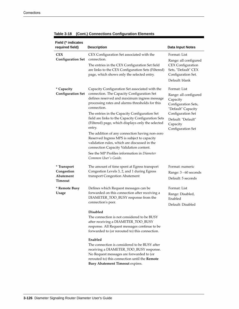
Table 3-18 (Cont.) Connections Configuration Elements
Field (* indicatesrequired field) Description Data Input Notes
CEXConfiguration Set
CEX Configuration Set associated with theconnection.
The entries in the CEX Configuration Set fieldare links to the CEX Configuration Sets (Filtered)page, which shows only the selected entry.
Format: List
Range: all configuredCEX ConfigurationSets, "Default" CEXConfiguration Set.
Default: blank
* CapacityConfiguration Set
Capacity Configuration Set associated with theconnection. The Capacity Configuration Setdefines reserved and maximum ingress messageprocessing rates and alarms thresholds for thisconnection.
The entries in the Capacity Configuration Setfield are links to the Capacity Configuration Sets(Filtered) page, which displays only the selectedentry.
The addition of any connection having non-zeroReserved Ingress MPS is subject to capacityvalidation rules, which are discussed in theconnection Capacity Validation content.
See the MP Profiles information in DiameterCommon User's Guide.
Format: List
Range: all configuredCapacityConfiguration Sets,"Default" CapacityConfiguration Set
Default: "Default"CapacityConfiguration Set
* TransportCongestionAbatementTimeout
The amount of time spent at Egress transportCongestion Levels 3, 2, and 1 during Egresstransport Congestion Abatement
Format: numeric
Range: 3 - 60 seconds
Default: 5 seconds
* Remote BusyUsage
Defines which Request messages can beforwarded on this connection after receiving aDIAMETER_TOO_BUSY response from theconnection's peer.
DisabledThe connection is not considered to be BUSYafter receiving a DIAMETER_TOO_BUSYresponse. All Request messages continue to beforwarded to (or rerouted to) this connection.
EnabledThe connection is considered to be BUSY afterreceiving a DIAMETER_TOO_BUSY response.No Request messages are forwarded to (orrerouted to) this connection until the RemoteBusy Abatement Timeout expires.
Format: List
Range: Disabled,Enabled
Default: Disabled
Connections
3-126 Diameter Signaling Router Diameter User's Guide

Table 3-18 (Cont.) Connections Configuration Elements
Field (* indicatesrequired field) Description Data Input Notes
Remote BusyAbatementTimeout
If Remote Busy Usage is set to Enabled or HostOverride, this defines the length of time inseconds the connection is considered BUSY fromthe last time a DIAMETER_TOO_BUSY responsewas received.
Format: numeric
Range: 3 - 60 seconds
Default: 5 seconds
Message PrioritySetting
Defines the source of Message Priority for aRequest message arriving on the connection.Possible settings are:• blank - use the Default Message Priority
Configuration Set• Read from Request Message - read the
message priority from the ingress Request(--- appears in the Message PriorityConfiguration Set column)
• User Configured - Apply the user-configured Message Priority ConfigurationSet selected for the connection
Format: options
Range: blank, Readfrom RequestMessage, UserConfigured
Default: blank
Message PriorityConfiguration Set
The Message Priority Configuration set used ifMessage Priority Setting is User Configured
Format: List
Range: all configuredMessage PriorityConfiguration Sets
Default: blank
Egress MessageThrottlingConfiguration Set
Egress Message Throttling Configuration Setassociated with the connection. The EgressMessage Throttling Configuration Set definesthe maximum Egress Message Rate andthresholds used to set the congestion level forthe connection.
The entries in the Egress Message ThrottlingConfiguration Set field are links to the EgressMessage Throttling Configuration Sets (Filtered)page, which displays only the selected entry.
Format: List
Range: all configuredEgress MessageThrottlingConfiguration Sets
Default: blank
Shared SecretConfiguration Set
The Shared Secret Configuration Set used forthis connection. (RADIUS only)
Format: List
Range: all configuredShared SecretConfiguration Sets
Default: -Select-
MessageAuthenticatorConfiguration Set
The Message Authenticator Configuration Setused for this connection. (RADIUS only)
Format: List
Range: all configuredMessageAuthenticatorConfiguration Sets
Default: -Select-
Connections
Configuring Diameter 3-127

Table 3-18 (Cont.) Connections Configuration Elements
Field (* indicatesrequired field) Description Data Input Notes
MessageConversionConfiguration Set
The Message Conversion Configuration Set MOassigned to this RADIUS connection. (RADIUSonly)
Format: list
Range: blank
Default: -Select-
Ingress Status-ServerConfiguration Set
The Ingress Status-Server Configuration Set usedfor this connection. (RADIUS only)
Format: List
Range: all configuredIngress Status-ServerConfiguration Sets
Default: -Select-
SuppressConnectionUnavailableAlarm
If checked, this suppresses the connectionattempts on the unavailable connections when aconnection attribute is configured and turnedON for the connection object, then theconnection unavailable alarm on thoseconnections is not raised.
Format: checkbox
Range: checked (YES)or unchecked (NO)
Default: unchecked
SuppressConnectionAttempts
If checked, suppresses the connection attemptswhen a diameter peer nodes status becomesavailable.
This attribute is not applicable for responderonly connection modes. It is only applicable forinitiator only and initiator and responderconnection modes. With any configuration editaction that results in connection mode toresponder only mode, the attribute value isreturned to the default value.
Format: checkbox
Range: checked (YES)or unchecked (NO)
Default: unchecked
Test Mode If checked, the connection is in Test Mode. Format: checkbox
Range: checked(YES), not checked(NO)
Default: not checked
Adding a Connection
Use this task to create a new Connection. The fields and configuration considerationsare described in Diameter Connection configuration elements.
1. Click Diameter > Configuration > Connections.
2. Click Insert.
The Diameter > Configuration > Connections [Insert] does not open if any of thefollowing conditions exist:
• There is no Local Node in the signaling Network Element (NE) to which theConnection can be assigned.
Connections
3-128 Diameter Signaling Router Diameter User's Guide

• There is no Peer Node in the signaling Network Element (NE) to which theConnection can be assigned.
Note: You cannot configure routes for OAM from the Network routes screenof the DSR GUI.
3. Enter a unique name for the Connection in the Connection Name field.
4. Select a AAA Protocol.
5. Select an option in the Transport Protocol field.
The Transport Protocol that you select for your Connection must match theprotocol supported by both the Local Node and the Peer Node for the Connection.
6. Select a Local Node from the list.
The Local Node must use the same IP protocol as the Peer Node you select. If youdo not see the Local Node you want to use, you might need to create a new LocalNode. See Adding a Local Node.
7. Select the Connection Mode from the list. See Diameter Connection configurationelements.
Responder Only connections associated with a Peer Node are not considered listenports (SCTP, TCP, TLS, or DTLS).
8. If you set up the Connection Mode for Initiator Only, you can optionally enter aLocal Initiate Port number in the field.
9. Select the Local IP Address from the list.
10. If the Transport Protocol is set to SCTP, then select the Alternate Local IP Addressof this Connection from the list.
11. Select a IPFE Initiator DAMP from the list.
This step is only needed for IPFE Initiator connections.
12. Select a Peer Node from the list.
Initiator port ranges are divided into user-assigned and DCL-assigned sub-ranges.Depending on the type of initiator connection, fixed or Floating IPFE, there are twoor more user/DCL sub-ranges. The Peer Node must use the same TransportProtocol as the Local Node that you selected. If you do not see the Peer Node youwant to use, you might need to create a new Peer Node. See Adding a Peer Node.
Diameter Transport Layer (DCL) is the software layer of the stack whichimplements diameter transport connections.
13. Select from the options in Peer Node Identification field.
14. If needed, select the Peer IP Address of this Connection from the Peer IP Addresslist.
15. If needed, select the Alternate Peer IP Address of this Connection from theAlternate Peer IP Address list.
16. If needed, enter a Transport FQDN for this Connection.
Connections
Configuring Diameter 3-129

17. Select a Connection Configuration Set from the list.
18. If one is needed, select a CEX Configuration Set from the list .
19. If the Per Connection Ingress MPS Control feature is active in the system, select aCapacity Configuration Set from the list.
20. Specify the Transport Congestion Abatement Timeout.
21. Select a Remote Busy Usage setting from the list.
22. If you selected Enabled or Host Override for Remote Busy Usage, set the RemoteBusy Abatement Timeout value.
23. Select from the options in Message Priority Setting field.
24. If you selected User Configured as the Message Priority Setting, select a MessagePriority Configuration Set from the list.
25. Make selections from the Egress Message Throttling Configuration Set, SharedConfiguration Set, Message Authenticator Configuration Set, and Ingress Status-Server Configuration Set lists.
26. Click the Suppress Connection Unavailable Alarm check box to suppress theConnection unavailable alarm.
27. Click the Suppress Connection Attempts check box to suppress the Connectionattempts to a standby Peer Node, c
28. Click Test Mode check box to the test Connection.
29. Click OK, Apply, or Cancel.
30. Use the Enabling Connections procedure to enable the new connection.
The following conditions exist:
• Only Peer Nodes whose Dynamic attribute is NO can be selected forassignment to a connection.
• Peer Nodes created by the Dynamic Peer Discovery feature cannot be assignedto any statically created connection.
• CEX Configuration Sets created by the Dynamic Peer Discovery feature cannotbe assigned to any statically created connection.
Editing a Connection
Use this task to edit an existing Connection.
1. Verify the Connection to be edited is in the Disabled Admin State. See how todisable a connection in Disabling Connections.
2. Click Diameter > Configuration > Connections.
3. Select the Connection you want to edit.
4. Click Edit.
The edit page does not open if any of the following conditions exist:
Connections
3-130 Diameter Signaling Router Diameter User's Guide

• The selected Connection no longer exists.
• The Connection is not in the Disabled Admin state.
5. Update the relevant fields.
See the Connection configuration elements description in Diameter Connectionconfiguration elements. The Connection Name cannot be edited.
Note: Uncheck the Test Mode checkbox to change from test connection tonormal connection. You cannot reverse this action.
Selecting the X at the end of a field clears the field. You can enter or select anothervalue.
6. Click OK, Apply, or Cancel.
The following conditions exist:
• Any request for a list of Connections does not include any dynamically createdConnection instances.
• Dynamic Peer Discovery can insert a connection instance whose Dynamicattribute is set to YES only.
• Dynamic Peer Discovery software can delete a Connection instance whoseDynamic attribute is set to YES only.
• If you attempt to edit a Connection whose Dynamic attribute set to NO, theEdit page only allows Peer Nodes and CEX Configuration Sets whose ownDynamic attribute set to NO the assigned Connection.
• If you attempt to edit a Connection whose Dynamic attribute set to YES, theEdit page only allows CEX Configuration Sets whose own Dynamic attributeset to NO the assigned Connection. A Connection whose Dynamic attribute setto YES or NO the assigned Connection.
• If you attempt to edit a Connection whose Dynamic attribute set to YES, theselection options for Connection Mode does not include Responder Only.
7. Use the Enabling Connections procedure to enable the edited Connection.
Deleting a Connection
Use this task to delete an existing Connection.
Note: You must disable a Connection before you can delete it. See DisablingConnections.
1. Click Diameter > Configuration > Connections.
2. Select the Connection you want to delete.
3. Click Delete.
A popup window appears to confirm the delete.
Connections
Configuring Diameter 3-131

4. ClickOK, Apply, or Cancel.
Diameter Route GroupsA Route Group is a user-configured set of Peer Nodes or Connections used todetermine the distribution of traffic to each Peer Node in the same Route Group.Traffic is distributed among available Peer Nodes or Connections based on theconfigured capacity assignment of each available Peer Node or Connection.
Note: Connection Route Groups is not supported for RADIUS connections,but can be configured with all RADIUS or all Diameter Peer Nodes.
You can perform these tasks on an Active System OAM (SOAM).
For example, if Peer Node A has a configured capacity of 100 and Peer Node B has aconfigured capacity of 150, then 40% of the messages sent to the Route Group isforwarded to Peer Node A and 60% of the messages is forwarded to Peer Node B.
Each Route Group can be assigned a maximum of 512 Connections. Route Groups areassigned to Route Lists.
Note: Route Groups created via Dynamic Peer Discovery cannot be assignedto any statically-created Route List.
On the Diameter > Configuration > Route Groups page, you can perform thefollowing actions:
• Filter the list of Route Groups to display only the desired Route Groups.
• Sort the list by the Route Group Name column in ascending or descending orderby clicking the column heading. The default order is ascending ASCII order.
• Click an entry that is shown in blue for a Peer Node/Connection.
• Click Insert.
On the Diameter > Configuration > Route Groups [Insert] page, you can add anew Route Group.
The Diameter > Configuration > Route Groups [Insert] does not open if themaximum number of Route Groups (6000) already exists in the system.
• Select a Route Group in the list and click Edit.
On the Diameter > Configuration > Route Groups [Edit] page, you can edit theselected Route Group.
If the selected Route Group has been deleted by another user, the Diameter >Configuration > Route Groups [Edit] page does not open.
• Select a Route Group in the list and click Delete. You can delete the selected RouteGroup.
Diameter Route Group configuration elementsTable 3-19 describes the fields on the Route Groups View, Insert, and Edit pages. DataInput Notes only apply to the Insert and Edit pages; the View page is read-only.
Diameter Route Groups
3-132 Diameter Signaling Router Diameter User's Guide

Note: Any request for a list of Route Groups does not include anydynamically-created route group instances.
When you select a Peer Node from a Peer Route Group or Connections from aConnection Route Group, you can specify to pass over Connections that have too highof a DOIC loss rate.
Table 3-19 Route Groups Configuration Elements
Field (* indicatesrequired field) Description Data Input Notes
* Route Group Name Unique name of the Route Group. Format: case-sensitive;alphanumeric andunderscore
Range: 1 - 32characters; cannot startwith a digit and mustcontain at least onealpha
Dynamic (View) Indicates whether or not the Route Groupwas created dynamically (YES) or statically(NO).
Format: text
Range: YES, NO
Default: NA
Type A Route Group can be configured witheither Peer Nodes (Peer Route Group) orConnections (Connections Route Group)that have the same priority within a RouteList.
Format: options
Range: Peer RouteGroup, ConnectionRoute Group
Default: Peer RouteGroup
Peer Node/Connection (View)
List of Peer Nodes or Connectionsconfigured for the Route Group.
Each listed Peer Node or Connection entryis a link to the Diameter > Configuration >{Entry Type} [Filtered] page for that entryonly.
Each entry displays a +sign and the number ofPeer Nodes orConnections assignedto that Route Group.Click the + sign todisplay the Peer Nodesor Connections; the +sign changes to a - sign.Click the - sign todisplay the numberagain.
* Peer Node,Connection, andProvisioned Capacity
One entry defined for a Route Group. Up to 512 entries can beconfigured for aConnection RouteGroup.
Click Add to insertanother entry for theRoute Group.
Diameter Route Groups
Configuring Diameter 3-133

Table 3-19 (Cont.) Route Groups Configuration Elements
Field (* indicatesrequired field) Description Data Input Notes
Peer Node
The Peer Node fieldis part of the PeerNode, Connection,and Capacity fieldsthat are combined onthe [Insert] and [Edit]pages.
A Peer Node associated with the RouteGroup. Each Route Group can be assignedup to 512 Peer Nodes.
The Peer Node field is available when thePeer Route Group option is selected in theType field.
The Peer Node field is required.
Format: List
Range: 1 - 160configured Peer Nodes
Connection
The Connection fieldis part of the PeerNode, Connection,and Capacity fieldsthat are combined onthe [Insert] and [Edit]pages.
A connection associated with the RouteGroup. Each Route Group can be assignedup to 512 connections.
The Connection field is available when theConnection Route Group option is selectedin the Type field and a Peer Node isselected.
The Connection field is required forConnection Route Groups.
Format: List
Range: 1 - 512configuredConnections for theselected Peer Node
Provisioned Capacity
The ProvisionedCapacity field iscombined with thePeer Node andConnection fields onthe [Insert] and [Edit]pages.
View page: Provisioned capacity for a RouteGroup, which is the sum total of configuredcapacity of peer nodes or connectionswithin a Route Group.
[Insert] and [Edit] pages: Provisionedcapacity of a Peer Node or Connectionwithin a Route Group. The ProvisionedCapacity field is required.
Traffic is distributed to available PeerNodes/Connections in a Route Groupproportional to the configured capacity forthe Peer Node/Connection. A Peer Node/Connection with a higher capacity isassigned more traffic.
Format: numeric
Range: 1 - 65535
Traffic Measurement Traffic measurements can be enabled for upto 250 route groups including peer andconnection route groups.
Format: options
Range: Enabled,Disabled
Default: Disabled
Adding a Route Group
Use this task to create a new Route Group.
1. Click Diameter > Configuration > Route Groups.
2. Click Insert.
3. Enter a unique name for the Route Group in the Route Group Name field.
Diameter Route Groups
3-134 Diameter Signaling Router Diameter User's Guide

4. Enable or disable traffic measurements in a route group by setting TrafficMeasurement.
5. Select the Type option for the entries included in the Route Group (Peer Nodes orConnections).
6. Select the Peer Node, or Peer Node and Connection, and enter the ProvisionedCapacity field for this Route Group entry.
a. Select a Peer Node from the Peer Node list.
b. If the Connection Route Group option is selected for the Type field, then selecta Connection assigned to the selected Peer Node from the Connection list.
c. Enter the Provisioned Capacity for the selected Peer Node or Connection.
7. Perform one of the following actions:
• If you want to add another Peer Node, Connection, and Provisioned Capacityentry to the Route Group, click Add and repeat step 6 for this next entry. Up to512 entries can be provisioned for Connection Route Groups.
• If you do not want to add another entry, continue with step 8.
8. Click OK, Apply, or Cancel.
If OK or Apply is clicked and any of the following conditions exist, then an errormessage appears:
• Any required field is empty; no value was entered or selected
• The entry in any field in not valid (wrong data type or out of the valid range)
• The Route Group Name is not unique; it already exists in the system
• The selected list entry no longer exists (has been deleted by another user)
• The selected Peer Node is a duplicate within the Route Group
• The selected Connection is a duplicate within the Route Group for the samePeer Node
• The maximum number of Route Groups (6000) already exists in the system
The following conditions exist:
• You can only assign Peer Nodes whose Dynamic attribute is NO to a RouteGroup of either type (Peer Node or Connection). Peer Nodes created viaDynamic Peer Discovery cannot be assigned to any statically-created RouteGroup.
• Peer Nodes created by the Dynamic Peer Discovery cannot be assigned to anystatically-created Route Group.
• You can only allow Connections whose Dynamic attribute is NO to a RouteGroup of type Connection Route Group.
• Connections created by the Dynamic Peer Discovery feature may not beassigned to any statically-created Connection Route Group.
Diameter Route Groups
Configuring Diameter 3-135

Editing a Route Group
Use this task to make changes to a Route Group.
When the Diameter > Configuration > Route Groups [Edit] page opens, the fields areinitially populated with the current values for the selected Route Group. The RouteGroup Name cannot be changed.
Note: When editing a Route Group, you can add only allow Peer Nodeswhose Dynamic attribute is NO be selected for assignment to a Route Groupof either type (Peer Node or Connection).
1. Click Diameter > Configuration > Route Groups.
2. Select the Route Group you want to edit.
3. Click Edit.
The page is initially populated with the current configured values for the selectedroute group.
To delete a Peer Node or a Connection from the Route Group, clear the Peer Nodeand Provisioned Capacity field values either by selecting --Select-- in the Peer Nodelist or by clicking the X at the end of the Provisioned Capacity list for the PeerNode.
The Type field can be changed only if the Route Group is not assigned to any RouteList.
When the Type field is changed, the Peer Node, Connection, and ProvisionedCapacity entries are reset to one entry with empty values. The Connection list isnot available when Peer Route Group is selected for the Type field.
4. Update the relevant fields.
For more information about each field, see Diameter Route Group configurationelements.
5. Click OK, Apply, or Cancel.
If OK or Apply is clicked and any of the following conditions exist, then an errormessage appears:
• If you attempt to add or edit a Route Group instance whose Dynamic attributeis YES.
• If you attempt to insert or edit a static Route Group or Connection RouteGroup of either type (Peer or Connection), and one or more of the Peer Nodessupplied in the desired configuration has a Dynamic attribute a value of YES.
• If you attempt to edit a static Route Group instance by changing its Dynamicattribute from NO to YES or vice-versa.
• If you attempt to delete a Route Group instance whose Dynamic attribute isYES.
• Any required field is empty; no value was entered or selected
Diameter Route Groups
3-136 Diameter Signaling Router Diameter User's Guide

• The entry in any field in not valid (wrong data type or out of the valid range)
• The selected list entry no longer exists (has been deleted by another user)
• The selected Peer Node is a duplicate within the Route Group
• The selected Connection is a duplicate within the Route Group for the samePeer Node
The following conditions exist:
• When editing a Route Group, you can only add Connections whose Dynamicattribute is NO be selected for assignment to a Connection Route Group.
• Connections created via Dynamic Peer Discovery cannot be assigned to anystatically-created Connection Route Group.
• A value of NO is assigned for the Dynamic attribute for all Route Groupinstances being inserted with the exception of instances added via DynamicPeer Discovery.
• Dynamic Peer Discovery can only delete a Route Group instance whoseDynamic attribute is YES.
Deleting a Route Group
Use this task to delete a Route Group.
Note: A Route Group cannot be deleted if it is included in any Route Lists.
1. Click Diameter > Configuration > Route Groups.
2. Select the Route Group you want to delete.
3. Click Delete.
A popup window appears.
4. Click OK orCancel.
If OK is clicked and the selected Route Group is referenced by at least one RouteList, then an error message appears and the Route Group is not deleted.
If OK is clicked and the selected Route Group no longer exists (it was deleted byanother user), then an error message appears and the Route Groups view isrefreshed.
Diameter Route ListsA Route List is a user-configured set of Route Groups used to determine thedistribution of traffic between each Route Group within the Route List. Each RouteList can include up to three Route Groups.
You can perform route lists tasks on an Active System OAM (SOAM).
Traffic distribution to a Route Group is based on its available capacity and assignedpriority within the Route List. A Route Group with a priority of 1 has the highestpriority and a Route Group with a priority of 3 has the lowest priority.
Diameter Route Lists
Configuring Diameter 3-137

Only one Route Group in a Route List is designated as the active Route Group forrouting messages for that Route List. The other Route Groups in the Route Listfunction as standby Route Groups. The active Route Group in each Route List isdetermined based on the Route Group's priority and its capacity relative to theconfigured minimum capacity of the Route List.
When the Operational Status of Peer Nodes assigned to the active Route Groupchanges, or the configuration of either the Route List or Route Groups in the Route Listchanges, then the designated active Route Group for the Route List may change.
Route Lists are assigned to Peer Routing Rules. When a Diameter message matches aPeer Routing Rule, the Route List assigned to the Peer Routing Rule directs theDiameter message to a Peer Node in the active Route Group.
Route Lists are assigned to Peer Nodes when Alternate Implicit Routing is used.
Route Lists are assigned to Message Copy Configuration Sets to be used for copying amessage to a DAS node.
On the Diameter > Configuration > Route Lists page, you can perform the followingactions:
• Filter the list of Route Lists to display only the desired Route Lists.
• Sort the list by the Route List Name column or the Minimum Route GroupAvailability Weight column in ascending or descending order by clicking thecolumn heading. The default order is by Route List Name in ascending ASCIIorder. The expanded rows of Route Groups are sorted by Priority.
• Click an entry that is shown in blue for a Route Group (in the expanded list).
• Click Insert.
On the Diameter > Configuration > Route Groups [Insert] page, you can add anew Route List.
The Diameter > Configuration > Route Groups [Insert] page does not open if :
– The maximum number of Route Lists (2000) already exists in the system
– There is no available Route Group
• Select a Route List in the list and click Edit.
On the Diameter > Configuration > Route Lists [Edit] page, you can edit theselected Route List.
If the selected Route List has been deleted by another user, the Diameter >Configuration > Route Lists [Edit] page does not open.
• Select a Route List in the list and click Delete. You can delete the selected RouteList.
Diameter Route List configuration elementsTable 3-20 describes the fields on the Route Lists View, Insert, and Edit pages. DataInput Notes only apply to the Insert and Edit pages; the View page is read-only.
Note: Any request for a list of Routes does not include any dynamically-created Route instances.
Diameter Route Lists
3-138 Diameter Signaling Router Diameter User's Guide

When you select Route Groups from a Route List, you can specify to pass over RouteGroups that have too high of a DOIC loss rate.
Table 3-20 Route Lists Configuration Elements
Field (* indicatesrequired field) Description Data Input Notes
* Route List Name Unique name for the Route List Format: case-sensitive;alphanumeric andunderscore (_);cannot start with adigit and mustcontain at least onealpha
Range: 1 - 32characters
Dynamic Indicates whether or not the element wascreated dynamically (YES) or statically (NO).NO is assigned for all element instances,except for those created via Dynamic PeerDiscovery.
Format: checkbox(read-only on theElement [Edit] page)
Range: checked (theelement was createdas a result ofDynamic Discovery),unchecked
Default: unchecked
* Minimum RouteGroup AvailabilityWeight
The minimum Route Group availabilityweight for this Route List.
The minimum weight is used to determine aRoute Group's availability status within aRoute List.
Format: numeric
Range: 1 - 1024000
* Route Group Route Groups associated with the Route List.
Up to three Route Groups can be associatedwith a single Route List.
On the View page, each entry displays a +sign and the number of Route Groupsassigned to that Route List. Click the + sign todisplay the Route Groups; the + sign changesto a - sign. Click the - sign to display thenumber again.
The Route Group entries in the expanded listare links to the Diameter > Configuration >Route Groups [Filtered]> page for theselected Route Group.
Format: List
Range: availableRoute Groups
* Priority The priority of the Route Group within theRoute List.
Priority is set from 1 (highest priority) to 3(lowest priority).
Format: numeric
Range: 1, 2, or 3
Diameter Route Lists
Configuring Diameter 3-139

Table 3-20 (Cont.) Route Lists Configuration Elements
Field (* indicatesrequired field) Description Data Input Notes
* Route Group Route Groups associated with this Route List. Format: List
Range: 1 - 3 entries
Default: NA
Site Name Site Name whose TTG is to be selected toassociate with the Route Group.
Format: List
Range: Local SiteOnly
Default: NA
Traffic ThrottleGroup
Traffic Throttle Group configured in the Siteselected (all local TTGs if local site is selectedand TTG marked as shared if remote site isselected).
Format: List
Range: NA
Default: NA
Maximum LossPercent Threshold
Maximum Loss Percent Threshold for thecombination of Route List, Route Group andTraffic Threshold Group
Format: List
Range: 0 - 100
Default: NA
Adding a Route List
Use this task to create a new Route List. The fields are described in Diameter RouteList configuration elements.
Note: You must have at least one Route Group configured before you cancreate a Route List.
1. Click Diameter > Configuration > Route Lists.
2. Click Insert.
3. Enter a unique name for the Route List in the Route List Name field.
4. Enter the Minimum Route Group Availability Weight in the field.
5. Enable or disable routing across alternate Route Groups in Route List by settingRoute Across Route Groups.
6. Select one to three Route Groups from the Route Group lists. For each Route Groupyou specify, select a Site Name, Traffic Throttle Group, and Maximum LossPercent Threshold.
The Site Name list includes the local SOAM (assuming that at least one TTG hasbeen configured).
Note: Traffic Throttle Group is disabled until a Site Name is selected.
7. Click OK, Apply, or Cancel.
Diameter Route Lists
3-140 Diameter Signaling Router Diameter User's Guide

If OK or Apply is clicked and any of the following conditions exist, then an errormessage appears:
• Any required field is empty; no value was entered or selected
• The entry in any field in not valid (wrong data type or out of the valid range)
• The Route List Name is not unique; it already exists in the system
• The selected list entry no longer exists (has been deleted by another user)
• A selected Route Group is a duplicate within the Route List
• A Route Group Priority is not unique within the Route List
• The maximum number of Route Lists (2000) already exists in the system
Editing a Route List
Use this task to make changes to existing Route Lists.
The Route List Name cannot be changed.
Note: If Dynamic (read-only checkbox) is checked, it means that the route listwas created as a result of Dynamic Peer Discovery.
1. Click Diameter > Configuration > Route Lists.
2. Select the Route List you want to edit.
3. Click Edit.
The page is initially populated with the current configured values for the selectedRoute List.
4. Update the relevant fields.
For more information about each field see Diameter Route List configurationelements.
5. Click OK, Apply, or Cancel.
If OK or Apply is clicked and any of the following conditions exist, then an errormessage appears:
• If you attempt to edit a Route List instance whose Dynamic attribute is YES, awarning message displays, but the edit operation is allowed to proceed.Editing a dynamic route is allowed, but changes are lost to this Route List if theRealm to which the Route List is associated is dynamically re-discovered in thefuture.
• If you attempt to delete a Route List instance whose Dynamic attribute is YES.
• If you attempt to insert or edit a static Route List, one or more of the RouteGroups supplied in the desired configuration has for its own Dynamicattribute a value of YES.
• If youattempt to change one or more read-only attributes.
Diameter Route Lists
Configuring Diameter 3-141

Note: When editing a Route List instance whose Dynamic attribute is YES,all Route List attributes are treated as read-only except for Route Across RouteGroups.
• If you attempt to edit a static Route List instance by changing its Dynamicattribute from NO to YES or vice-versa.
• If youattempt to add a Route List instance and the Dynamic attribute is YES. ARoute List instanceDynamic attribute must be YES to be inserted usingDynamic Peer Discovery.
• Any required field is empty; no value was entered or selected
• The entry in any field in not valid (wrong data type or out of the valid range)
• The selected Route List no longer exists (has been deleted by another user)
• A selected Route Group no longer exists (has been deleted by another user)
• A selected Route Group is a duplicate within the Route List
• A Route Group Priority is not unique within the Route List
Deleting a Route List
Use this task to delete a Route List.
Note: A Route List cannot be deleted if any of the following conditions aretrue:
• The Route List is referenced by any Peer Node as the Alternate ImplicitRoute
• The Route List is referenced by any Peer Routing Rule
• The Route List is set as the Route List for DAS Node in any MessageCopy Configuration Set
1. Click Diameter > Configuration > Route Lists.
2. Select the Route List you want to delete.
3. Click Delete.
A popup window appears to confirm the delete.
4. Click OK or Cancel.
If OK is clicked and the selected Route List no longer exists (it was deleted byanother user), an error message displays and the Route Lists view is refreshed.
Diameter Peer Route TablesA Peer Route Table is a set of prioritized Peer Routing Rules that DRL searches withthe content of a Request message received from Diameter Nodes and applications todetermine how to route the message to a Peer Node.
Diameter Peer Route Tables
3-142 Diameter Signaling Router Diameter User's Guide

You can perform these tasks on an Active System OAM (SOAM).
Users can assign Peer Route Table (PRT) to Diameter messages based on ApplicationID and (Extended) Command Codes by configuring Transaction Configuration Rule(TCR) with Application ID plus (E)CC as a key in Transaction Configuration Sets.
On the Diameter > Configuration > Peer Route Tables page, you can perform thefollowing actions:
• Filter the list of Peer Route Tables to display only the desired Peer Route Tables.
• Sort the list by a column in ascending or descending order by clicking the columnheading. The default order is by Peer Route Table Name in ascending ASCIIorder.
• Click Insert.
On the Diameter > Configuration > Peer Route Tables [Insert] page, you can adda new Peer Route Table.
The Diameter > Configuration > Peer Route Tables [Insert] page does not open if
– The maximum number of Peer Route Tables (500) already exists in the system.
• Select a Peer Route Table in the list and click View/Edit Rules.
On the Viewing Rules for Peer Route Table page, you can select a Rule Name towork with.
If the selected Peer Route Table has been deleted by another user, the ViewingRules for Peer Route Table page does not open.
• Select a Peer Route Table in the list and click Delete. You can delete the selectedPeer Route Table.
Diameter Peer Route Tables elementsTable 3-21 describes the fields on the Peer Route Tables View and Insert pages. DataInput Notes apply only to the Insert page; the View page is read-only.
Table 3-21 Peer Route Tables Elements
Field (* indicatesrequired field) Description Data Input Notes
* Peer Route TableName
Unique name of the Peer RouteTable.
Format: case-sensitive;alphanumeric and underscore
Range: 1 - 32 characters;cannot start with a digit andmust contain at least onealpha
Number of Rules The number of Peer Routing Rulesin the Peer Route Table.
Adding a Peer Route Table
Use this task to create a new Peer Route Table. The fields are described in DiameterPeer Route Tables elements.
Diameter Peer Route Tables
Configuring Diameter 3-143

1. Click Diameter > Configuration > Peer Route Tables.
2. Click Insert.
3. Enter a unique name for the Peer Route Table in the Peer Route Table Name field.
4. Click OK, Apply, or Cancel.
If OK or Apply is clicked and any of the following conditions exist, then an errormessage appears:
• Any required field is empty; no value was entered or selected
• The entry in any field in not valid (wrong data type or out of the valid range)
• The Peer Route Table Name is not unique; it already exists in the system
• The maximum number of Peer Route Tables (500) already exists in the system
After a Peer Route Table is added, Peer Routing Rules can be defined for it. See PeerRouting Rules configuration. For information about required component configurationorder, see Understanding the Diameter Configuration Sequence.
Deleting a Peer Route Table
Use this task to delete a Peer Route Table.
Note: An Application Route Table cannot be deleted if any of the followingconditions are true:
• The Peer Route Table is referenced by any Peer Node
• The Peer Route Table is referenced by any Transaction Configuration Set
• The selected default Peer Route Table is the Default Peer Route Table
• The Peer Route Table is referenced by the DM-IWF Options configuration
• If OK is clicked and the selected Application Route Table is currentlyreferenced by any Transaction Configuration Set, the request is rejectedand an error message displays.
1. Click Diameter > Configuration > Peer Route Tables.
2. Select the Peer Route Table you want to delete.
3. Click Delete.
A popup window appears to confirm the delete.
4. Click:
• OK to delete the Peer Route Table.
• Cancel to cancel the delete function and return to the Diameter >Configuration > Peer Route Tables page.
Diameter Peer Route Tables
3-144 Diameter Signaling Router Diameter User's Guide

If OK is clicked and the selected Peer Route Table no longer exists (it was deletedby another user), an error message displays.
If OK is clicked and the selected Peer Route Table is currently referenced by theDM-IWF Options configuration, the request is rejected and an error messagedisplays.
Peer Routing Rules configurationPeer Routing Rules are prioritized lists of user-configured routing rules that definewhere to route a message to upstream Peer Nodes. Routing is based on messagecontent matching a Peer Routing Rule's conditions. Peer Routing Rules are containedin Peer Route Tables.
Note: When a Redirected Request is processed, if redirect PRT instance is notconfigured, the PRT instance used to Process the redirected Request is selectedsimilar to an ingress request.
There are six Peer Routing Rule parameters:
• Destination-Realm
• Destination-Host
• Application-ID
• Command-Code
• Origin-Realm
• Origin-Host
When a Diameter message matches the conditions of a Peer Routing Rule then theaction specified for the rule occurs. If you choose to route the Diameter message to aPeer Node, the message is sent to a Peer Node in the selected Route List based on theRoute Group priority and Peer Node configured capacity settings. If you choose toSend an Answer, then the message is not routed and the specified Diameter AnswerCode is returned to the sender.
Peer Routing Rules are assigned a priority in relation to other Peer Routing Rules. Amessage is handled based on the highest priority routing rule that it matches. Thelower the number a Peer Routing Rule is assigned, the higher priority it has. (1 is thehighest priority and 99 is the lowest priority.)
If a message does not match any of the Peer Routing Rules and the Destination-Hostparameter contains a Fully Qualified Domain Name (FQDN) matching a Peer Node,then the message is directly routed to that Peer Node if it has an available Connection.
If there is not an available Connection or all routing attempts (per Peer Nodeconfiguration) to the implicit route are exhausted, the message is routed using thealternate implicit route configured for the Peer Node.
A Message Copy Configuration Set can be assigned to a Peer Routing Rule to provideinformation for sending a copy of the message to a DAS.
On the Viewing Rules for Peer Route Table: {Peer Route Table Name} page, you canperform the following actions:
• Filter the list of Rule Names to display only the desired Rules.
Diameter Peer Route Tables
Configuring Diameter 3-145

• Sort the list entries in ascending or descending order by column (exceptConditions) by clicking the column heading.
By default, the list is sorted by Priority in ascending ASCII order. The lowestPriority value indicates the highest priority. For Rules with the same Priority, theRule Name is used for sorting.
• Select a blue Route List entry to open the Diameter > Configuration > RouteLists [Filtered] page for the selected entry.
• Click Insert.
On the Inserting Rule for Peer Route Table: {Peer Route Table Name} page, youcan add a new Peer Routing Rule and its values. See Adding a Peer Routing Rule.
If the maximum number of Peer Routing Rules (10000) already exists for the PeerRoute Table, the Inserting Rule for Peer Route Table: {Peer Route Table Name}page does not open and an error message displays.
• Select the Rule Name of a Peer Routing Rule in the list and click Edit.
On the Editing Rule for Peer Route Table: {Peer Route Table Name} page, you canedit the selected Peer Routing Rule. See Editing a Peer Routing Rule.
If the selected Peer Routing Rule has been deleted by another user, the EditingRule for Peer Route Table: {Peer Route Table Name} page does not open.
• Select the Rule Name of a Peer Routing Rule in the list and click Delete to removethe selected Peer Routing Rule. See Deleting a Peer Route Rule.
Peer Routing Rule configuration elements
Table 3-22 describes the fields on the Peer Routing Rules View, Edit, and Insert pages.Data input notes apply only to the Insert and Edit pages; the View page is read-only.
Table 3-22 Peer Routing Rules Configuration Elements
Field (*indicatesrequired field) Description Data Input Notes
* Rule Name Unique name of the Peer Routing Rule. Format: case-sensitive;alphanumeric andunderscore (_); cannot startwith a digit and must containat least one alpha
Range: 1 - 32 characters
* Peer RouteTable
The Peer Route Table to which the peerrouting rule belongs
View-only
* Priority Priority of the rule in relation to otherrules.
The priority is set from 1 (highest priority)to 99 (lowest priority).
Format: text box; numeric
Range: 1 - 99
Diameter Peer Route Tables
3-146 Diameter Signaling Router Diameter User's Guide

Table 3-22 (Cont.) Peer Routing Rules Configuration Elements
Field (*indicatesrequired field) Description Data Input Notes
* Conditions For a diameter message to be matched by a rule, the message must matcheach specified part of a condition.
Each condition has three parts:• Parameter• Operator• Value
Parameter:
• Destination-Realm• Destination-Host• Application-ID• Command-Code• Origin-Realm• Origin-Host
Format: Operator and Valuefor each Parameter
Operator:
Sets the relationship between theparameter and the value. For example, ifthe operator is set to equals then thediameter message parameter must matchthe set value.
Format: List
Range: For a description ofoperators, see Peer RoutingRule operators.
Diameter Peer Route Tables
Configuring Diameter 3-147

Table 3-22 (Cont.) Peer Routing Rules Configuration Elements
Field (*indicatesrequired field) Description Data Input Notes
Value:
The value in the diameter message thepeer routing rule uses to determine amatch.
A value is required if the operator isequals, starts with, or ends with.
The value field is disabled for theoperators present, absent, and always true.
Format: text box or list
Range:• Destination-Realm and
Origin-Realm• Destination-Host and
Origin-Host• Application-ID• Command-Code• Command-Code
Note: An ECC is aCommand Code thatalso takes into accountthe value of a specificAVP for that CommandCode that gives the truecommand type (forexample, CCR-I, CCR-U,and so on).
Range: One or moreParameters with Operatorand Value for each Parameter
Default for Application-IDand Command Code: -Select-
Diameter Peer Route Tables
3-148 Diameter Signaling Router Diameter User's Guide

Table 3-22 (Cont.) Peer Routing Rules Configuration Elements
Field (*indicatesrequired field) Description Data Input Notes
Action The action that happens if the diametermessage matches the conditions set in thepeer routing rule:
• Route to Peer routes a message to apeer node using the Route Listassociated with this rule.
• Send Answer abandons messagerouting and sends an answer responsecontaining the required result-codevalue to associated with this rule.
• Abandon With No Answer discardsthe message routing and no answer issent to the associated peer.
Note: The answer is sent to anyapplications that requested an answerreceive.
• Forward To Peer Route Tableforwards the message to the specifiedpeer route table.
Format: options
Range: Route to Peer, SendAnswer, Abandon With NoAnswer, or Forward To PeerRoute Table
Default: Route to Peer
Route List Route list associated with this rule.
A route list is required if the action is set toroute to peer.
The route list entries on the view page arelinks to the Diameter > Configuration >Route Lists [Filtered] page for the selectedentry.
Note: You can only specify route listswhose dynamic attribute is NO to beselected for inclusion in a peer route rule.Also, you cannot include route lists createdby the dynamic peer discovery featurecannot be included by any peer route ruleinstance.
Format: List
Range: configured RouteLists
Default: -Select-
MessagePriority
The priority to assign to the message. Themessage priority is assigned only whenaction is set to route to peer.
Format: List
Range: No Change, 0 - Max(Maximum Normal RequestPriority as defined in SystemOptions)
Default: No Change
Diameter Peer Route Tables
Configuring Diameter 3-149

Table 3-22 (Cont.) Peer Routing Rules Configuration Elements
Field (*indicatesrequired field) Description Data Input Notes
Message CopyConfigurationSet
Message Copy Configuration Set (MCCS)used for copying the messages to the DAS.A valid MCCS marks the messagesmatched by this peer route rule for copy tothe DAS.
Format: List
Range: Default; configuredMessage Copy ConfigurationSets
Default: -Select-
Answer Result-Code Value
The answer code associated with this rule.
A diameter answer code is required if theaction is set to send Answer.
Format: options
Range:• List of the available
diameter answer codes• numeric 4 digit value
Range: 1000 - 5999
Default: NA
Vendor ID The Vendor ID to place in the vendor IDAVP of the answer message.
Format: numeric
Range: 0 - 4294967295
Answer ErrorMessage
Value returned in the Error-Message AVPof the answer message.
Format: text box
Range: 0 - 64 characters
Default: Null string
Target PeerRoute Table
The table specified in action as forward topeer route table. In the view only screen,the peer route table links to the Diameter >Configuration > Peer Route Tables(Filtered)
View-only
* Peer RouteTable
Peer route table associated with this rule. View-only
Peer Routing Rule operators
Table 3-23 describes the condition operators available for each parameter in a PeerRouting Rule.
Diameter Capacity Summary provides the maximum number of configurable rules (asdefined in DpiCapacityConstraints table, MaxPrtRulesWithContainsPerPrt,MaxCondWithContainsPerPrr, and MaxCharPrtCondWithContains) with the Containsoperator per PRT-Name.
Note: For runtime performance and resources efficiencies, only one conditionwith Contains operator in a rule is allowed.
Diameter Peer Route Tables
3-150 Diameter Signaling Router Diameter User's Guide

Table 3-23 Peer Routing Rules Operators
Parameter Operator Meaning
Destination-Realm Equals content must equal the value specified
Not Equal content must not equal the value specified
Starts With content must start with the value specified
Ends With content must end with the value specified
Contains content must contain the value specified
Always True content is not evaluated and the parameter'scondition is always true
Destination-Host Equals content must equal the value specified
Present and NotEqual
Destination-Host must be present and valuemust not equal the value specified
Starts With content must start with the value specified
Ends With content must end with the value specified
Contains content must contain the value specified
Present Destination-Host must be present
Absent Destination-Host must be absent
Always True content is not evaluated and the parameter'scondition is always true
Application-ID Equals content must equal the value specified
Not Equal content must not equal the value specified
Always True content is not evaluated and the parameter'scondition is always true
Command-Code Equals content must equal the value specified
Not Equal content must not equal the value specified
Always True content is not evaluated and the parameter'scondition is always true
Origin-Real Equals content must equal the value specified
Not Equal content must not equal the value specified
Starts With content must start with the value specified
Ends With content must end with the value specified
Contains content must contain the value specified
Always True content is not evaluated and the parameter'scondition is always true
Origin-Host Equals content must equal the value specified
Not Equal content must not equal the value specified
Diameter Peer Route Tables
Configuring Diameter 3-151

Table 3-23 (Cont.) Peer Routing Rules Operators
Parameter Operator Meaning
Starts With content must start with the value specified
Ends With content must end with the value specified
Contains content must contain the value specified
Always True content is not evaluated and the parameter'scondition is always true
Adding a Peer Routing Rule
Use this task to create a new Peer Routing Rule in a Peer Route Table.
1. Click Diameter > Configuration > Peer Route Tables.
2. Select the Peer Route Table to which you want to add a Peer Routing Rule and clickView/Insert Rules.
3. Click Insert.
4. Enter a unique name for the Rule in the Name field.
5. Set a Priority for this Rule in relation to other Rules by entering a number between1 and 99 in the Priority field.
6. Set the Peer Routing Rule Conditions:
a. Locate the Parameter you want to set.
b. Select the relevant operator from the Operator list. See Peer Routing Ruleoperators for a description of operators available for each parameter.
c. Enter the appropriate value for the parameter in the corresponding Value field.
d. Repeat this step for each parameter. For any parameter that does not need to beevaluated, set the Operator to Always True.
7. Select the Action you want to occur when a Diameter message matches theparameter conditions.
• Route to Peer: route the message to a Peer Node using the Route Listassociated with this Rule.
• Send Answer: abandon message routing and send an Answer responsecontaining the Answer Result-Code Value associated with this Rule.
8. If you selected Route to Peer as the Action, select the Route List to associate withthis Rule from the list.
9. If you selected Route to Peer as the Action, select the Message Priority to assign tothe message.
10. If Diameter Message Copy is used, select the Message Copy Configuration Set touse when this Rule is selected for PRT-triggered Message Copy.
Diameter Peer Route Tables
3-152 Diameter Signaling Router Diameter User's Guide

11. If you selected Send Answer as the Action, select the desired Answer Result-CodeValue selection box:
• Select the option to use an existing Answer Result-Code, then select an AnswerResult-Code in the list.
• Select the option and enter your own Answer Result-Code value.
12. If you selected Send Answer as the Action, enter the desired Vendor ID AVP in theVendor ID field.
13. If you selected Send Answer as the Action, enter the desired Error-Message AVP inthe Answer Error Message field.
14. Click OK, Apply, or Cancel
Editing a Peer Routing Rule
Use this task to edit a Peer Routing Rule in a Peer Route Table.
The Rule Name cannot be changed.
1. Click Diameter > Configuration > Peer Route Tables.
2. Select the Peer Route Table which contains the Peer Routing Rule you want to editand click View/Edit Rules.
3. Select the Peer Routing Rule you want to edit, then click Edit.
4. Update the relevant fields.
For more information about each field see Peer Routing Rule configurationelements and Peer Routing Rule operators.
5. Click:
• OK to save the data and return to Viewing Rules for Peer Route Table: {PeerRoute Table Name} page.
• Apply to save the data and remain on this page.
• Cancel to return to the Viewing Rules for Peer Route Table: {Peer Route TableName} page without saving any changes.
The following condition exists:
• Peer Route Rules are always statically configured; no statically configuredinstance can refer to a dependent GUI element that was added to theconfiguration as a result of Dynamic Peer Discovery.
If OK or Apply is clicked and any of the following conditions exist, then an errormessage appears:
• If you attempt to insert or update a Peer Route Rule instance and the specifiedRoute List whose Dynamic attribute value is YES.
• Any required field is empty (no entry was made)
• Any field is not valid or is out of range
Diameter Peer Route Tables
Configuring Diameter 3-153

• The selected Peer Routing Rule no longer exists (was deleted by another user)
• The selected Route List no longer exists (was deleted by another user)
• The Rule is similar to an already existing Rule (the same attributes except forRule Name and Priority)
Deleting a Peer Route Rule
Use this task to delete a Peer Routing Rule from a Peer Route Table.
1. Click Diameter > Configuration > Peer Route Tables.
2. Select the Peer Route Table that contains the Peer Routing Rule you want to deleteand click View/Edit Rules.
3. Select the Peer Routing Rule you want to delete.
4. Click Delete.
A popup window appears to confirm the delete.
5. Click:
• OK to delete the Peer Routing Rule.
• Cancel to cancel the delete function and return to the Viewing Rules for PeerRoute Table: {Peer Route Table Name} page.
If OK is clicked and the selected Peer Routing Rule no longer exists (it was deletedby another user), an error message displays and the Peer Routing Rules viewrefreshes.
Diameter Egress Throttle GroupsEgress Throttle Groups are used to monitor egress Request rate and pendingtransactions for multiple Peers and Connections across multiple DA-MPs. If a Peer isassigned to the Egress Throttle Group, then all Diameter Connections to that peer areimplicitly part of the Egress Throttle Group.
You can perform these tasks on an Active System OAM (SOAM).
Egress Throttle Group functions are described in detail in Egress Throttle Groups.Egress Throttle Groups control the following functions.
An Egress Throttle Group can be standalone, or it can be associated with an EgressThrottle List that spans multiple signaling routers. An Egress Throttle Group can beassociated with only one Egress Throttle List. See Diameter Egress Throttle List.
• Egress Throttle Group Rate Limiting controls the total egress Request traffic that isrouted to a configured group of Peers or Connections.
• Egress Throttle Group Pending Transaction Limiting controls the number ofpending transactions that are allowed for a configured group of Peers orConnections.
• The Egress Throttle Group Rate Limiting and Egress Throttle Group PendingTransaction Limiting provide egress throttling capability that enables:
Diameter Egress Throttle Groups
3-154 Diameter Signaling Router Diameter User's Guide

– A group of Peers and Connections to be associated with an Egress ThrottleGroup
– The maximum egress Request rate of Egress Throttle Groups to be set
– The maximum pending transaction limit of Egress Throttle Groups to be set
– The Egress Throttling Control Scope.
On the Diameter > Configuration > Egress Throttle Groups page, the followingactions can be performed:
• Filter the list of Egress Throttle Groups to display only the desired Egress ThrottleGroups.
• Sort the list by a column in ascending or descending order by clicking the columnheading.
The default order is by Egress Throttle Groups Name in ascending ASCII order.
• Click Insert.
On the Diameter > Configuration > Egress Throttle Groups [Insert] page, youcan add new Egress Throttle Groups.
The Diameter > Configuration > Egress Throttle Groups [Insert] page does notappear if the maximum number of Egress Throttle Groups (128 per NE) alreadyexists in the system.
• Select an Egress Throttle Group in the list and click Edit.
On the Diameter > Configuration > Egress Throttle Groups [Edit] page, you canedit the selected Egress Throttle Group.
If the selected Egress Throttle Group has been deleted by another user, then theDiameter > Configuration > Egress Throttle Groups [Edit] page does not open.
• Select an Egress Throttle Group in the list and click Delete to delete the selectedEgress Throttle Group.
Diameter Egress Throttle Groups elementsTable 3-24 describes the fields on the Diameter > Configuration > Egress ThrottleGroups page.
Table 3-24 Egress Throttle Groups Elements
Field (* indicatesa required field) Description Data Input Notes
* Egress ThrottleGroup Name
A name that uniquely identifies the EgressThrottle Group.
Format: text box;alphanumeric andunderscore; must containat least one alpha andmust not start with a digit.
Range: 1 - 32 characters
Default: NA
Diameter Egress Throttle Groups
Configuring Diameter 3-155

Table 3-24 (Cont.) Egress Throttle Groups Elements
Field (* indicatesa required field) Description Data Input Notes
Rate Limitingconfiguration set
Available Rate Limiting configuration setsfor this ETG.
Format: List
Range: NA
Default: NA
PendingTransactionLimitingConfiguration Set
Available Pending Transaction Limitingconfiguration sets for this ETG.
Format: List
Range: NA
Default: NA
Egress ThrottlingControl Scope
The control scope used to determine if theETG's aggregated data or the ETL'saggregated data is used for routingdecisions.
Note: The Egress Throttling ControlScope can be set to ETL only when the ETGhas been added to an Egress Throttle Listthrough the NOAM GUI. See DiameterEgress Throttle List.
Format: two options; onemust be checked.
Range: ETL or ETG
Default: ETG checked
Peer Node Peers associated with this Egress ThrottleGroup.
Note: Click Add to add Peer Nodes.
Format: List
Range: 0 - 128
Default: NA
Connection Connection associated with this EgressThrottle Group.
Note: Click Add to add Connections.
Format: List
Range: 0 - 128
Default: NA
Adding Egress Throttle Groups
Use this task to create new Egress Throttle Groups.
Egress Throttle Groups fields are described in Diameter Egress Throttle Groupselements.
1. Click Diameter > Configuration > Egress Throttle Groups.
2. Click Insert.
3. Enter a unique name for the Egress Throttle Group in the Egress Throttle GroupName field.
Diameter Egress Throttle Groups
3-156 Diameter Signaling Router Diameter User's Guide

4. Select a Rate Limiting configuration set.
5. Select a Pending Transaction Limiting Configuration Set.
6. Select a Egress Throttling Control Scope option.
7. Select a Peer Node to associate with this ETG.
8. Select a Connection to associate with this ETG.
9. Click:
• OK to save the changes and return to the Diameter > Configuration > EgressThrottle Groups page.
• Apply to save the changes and remain on this page.
• Cancel to return to the Diameter > Configuration > Egress Throttle Groupspage without saving any changes.
The following conditions exist:
• You can only insert Peer Nodes or Connections whose Dynamic attribute isNO for inclusion in an Egress Throttle Group.
• Peer Nodes or Connections created by the Dynamic Peer Discovery featurecannot be included by any Egress Throttle Group instance.
If OK or Apply is clicked and any of the following conditions exist, then an errormessage appears:
• The maximum number of Egress Throttle Groups have already been created.
• There is no Peer Node or Connection in the signaling network elementcorresponding to the Egress Throttle Group to be added.
• Any required fields are left empty.
• An Egress Throttle Group is configured with the greater than the maximumtotal number of Peers and Connections.
• An Egress Throttle Group is configured with duplicate Peers or Connections.
• An Egress Throttle Group is configured with a Peer already configured as amember in any Egress Throttle Group. (Explicit association of Peer withanother Egress Throttle Group)
• An Egress Throttle Group is configured with a Peer which is associated with aConnection configured as a member in any Egress Throttle Group. (Implicitassociation of Peer with another Egress Throttle Group)
• An Egress Throttle Group is configured with a Connection already configuredas a member in any Egress Throttle Group. (Explicit association of Connectionwith another Egress Throttle Group)
• An Egress Throttle Group is configured with a Connection which is associatedwith a Peer configured as a member in any Egress Throttle Group. (Implicitassociation of Connection with another Egress Throttle Group)
Diameter Egress Throttle Groups
Configuring Diameter 3-157

• An Egress Throttle Group is configured with a Connection and a Peerassociated with each other.
Editing Egress Throttle Groups
Use this task to edit Egress Throttle Groups.
When the Diameter > Configuration > Egress Throttle Groups [Edit] page opens, thecolumns are initially populated with the current configuration of the selected EgressThrottle Group.
The existing Egress Throttle Groups Name cannot be changed.
Changes can be made to an Egress Throttle Group configuration irrespective of theOperational Status of the associated Peer Connections.
Use this GUI page to change configuration sets and set the Egress Throttling ControlScope.
Egress Throttle Groups fields are described in Diameter Egress Throttle Groupselements.
1. Click Diameter > Configuration > Egress Throttle Groups.
2. Select the Egress Throttle Groups to be edited and click Edit.
3. Update the relevant fields.
An entry in a list can be removed by selecting the entry in the list and clicking the Xto the right of the list.
4. Click:
• OK to save the changes and return to the Diameter > Configuration > EgressThrottle Groups page.
• Apply to save the changes and remain on this page.
• Cancel to return to the Diameter > Configuration > Egress Throttle Groupspage without saving any changes.
The following conditions exist:
• You can only edit Peer Nodes or Connections whose Dynamic attribute is NOfor inclusion in an Egress Throttle Group.
• Peer Nodes or Connections created by the Dynamic Peer Discovery featurecannot be included by any Egress Throttle Group instance.
If OK or Apply is clicked and any of the following conditions exist, then an errormessage appears:
• An attempt is made to remove the Rate Limiting Egress Throttling byremoving the check from the corresponding Egress Throttlings check box foran Egress Throttle Group for which the Rate Limiting Admin State is set toEnabled.
• An attempt is made to remove Pending Transaction Egress Throttling byremoving the check from the corresponding Egress Throttlings check box foran Egress Throttle Group for which the Pending Transaction Limiting AdminState is set to Enabled.
Diameter Egress Throttle Groups
3-158 Diameter Signaling Router Diameter User's Guide

Deleting Egress Throttle Groups
Use this task to delete Egress Throttle Groups.
An Egress Throttle Group cannot be deleted if either its corresponding Rate LimitingAdmin State or Pending Transaction Limiting Admin State is not in the Disabledadmin state. Before you perform this task, ensure that the Rate Limiting Admin Stateor Pending Transaction Limiting Admin State for the Egress Throttle Group is in theDisabled admin state.
1. Click Diameter > Configuration > Egress Throttle Groups.
2. Select the Egress Throttle Group to be deleted.
3. Click Delete.
A popup window appears to confirm the delete.
4. Click:
• OK to delete the Egress Throttle Group.
• Cancel to cancel the delete function and return to the Diameter >Configuration > Egress Throttle Groups page.
If OK is clicked and the following condition exists, then an error message appears:
• The Egress Throttle Group Rate Limiting Admin State for the Egress ThrottleGroup to be deleted is not in the Disabled admin state.
• The Egress Throttle Group Pending Transaction Limiting Admin State for theEgress Throttle Group to be deleted is not in the Disabled admin state.
• The Egress Throttle Group is configured in an Egress Throttle List. The EgressThrottle Group must be removed from the Egress Throttle List in the NOAMGUI before it can be deleted.
Diameter Reroute On AnswerUsing Reroute On Answer, you can configure rerouting scenarios based on theApplication ID and Result-Code AVP values in Answer messages. If these valuesmatch the configured order pair of Application ID and Result-Code AVP value, themessage is rerouted to another available Peer Node from the Route Group selectedduring the routing process.
You can perform these tasks on an Active System OAM (SOAM).
If there are no additional available Peer Nodes in the selected Route Group, or themaximum number of transmits has been met, then reroute is not attempted and theAnswer is sent back to the originator.
On the Diameter > Configuration > Reroute on Answer page, you can perform thefollowing actions:
• Filter the list to display only the desired entries.
Diameter Reroute On Answer
Configuring Diameter 3-159

• Sort the list by column in ascending or descending order by clicking the columnheading. The default order is by Answer Result Code-AVP Value in ascendingASCII order.
• Click Insert.
On the Diameter > Configuration > Reroute on Answer [Insert] page, you canadd a new entry.
The Diameter > Configuration > Reroute on Answer [Insert] does not open if themaximum number of Reroute on Answer entries (1000) already exists in thesystem.
• Select a Reroute on Answer entry and click Delete to delete the selected entry.
Diameter Reroute On Answer configuration elementsTable 3-25 describes the fields on the Reroute On Answer View and Insert pages. DataInput Notes apply only to the Insert page; the View page is read-only.
Table 3-25 Reroute On Answer Configuration Elements
Field (* indicatesrequired field) Description Data Input Notes
* Answer Result-Code AVP Value
Value in the result-code AVP of the Answermessage.
Format: numeric
Range: 0 - 4294967295
Application ID Application ID in the Answer message thatidentifies a Diameter Application. It iscommonly used for screening and routingmessages between Diameter nodes.
The Internet Assigned Numbers Authoritylists standard and vendor-specificApplication IDs on their iana.org website. Onthe website:• Select Protocol Assignments• Scroll to locate the Authentication,
Authorization, and Accounting (AAA)Parameters heading
• Select Application IDs under theheading
Format: options, textbox, and list
Range:• first option: ALL• second option:
list withavailableApplication IDs
Default: ALL
Adding a Reroute On Answer entry
Use this task to create a new Reroute On Answer entry.
The fields are described in Diameter Reroute On Answer configuration elements.
1. Click Diameter > Configuration > Reroute On Answer.
2. Click Insert.
3. Enter the desired Result-Code AVP in the Answer Result-Code AVP Value field.
4. Perform one of the following actions for Application ID:
Diameter Reroute On Answer
3-160 Diameter Signaling Router Diameter User's Guide

• Select ALL to apply the Reroute On Answer entry to all Application IDs.
• Select the second option and select the appropriate Application ID from thelist.
5. Click:
• OK to save the changes and return to the Diameter > Configuration > Rerouteon Answer page.
• Apply to save the changes and remain on this page.
• Cancel to return to the Diameter > Configuration > Reroute on Answer pagewithout saving any changes.
If OK or Apply is clicked and any of the following conditions exist, then an errormessage appears:
• A field is empty; a value was not entered
• A value is not valid
• The Answer Result-Code AVP Value and Application ID combination is notunique; it already exists in the system
• Adding the new Reroute on Answer entry would cause the maximum numberof Reroute on Answer entries (1000) to be exceeded
Deleting a Reroute On Answer
Use this task to delete a Reroute On Answer entry.
1. Click Diameter > Configuration > Reroute On Answer.
2. Select the Answer Result-Code AVP Value for the Reroute On Answer you want todelete.
A popup window appears to confirm the delete.
3. Click Delete.
4. Click:
• OK to delete the Reroute on Answer entry.
• Cancel to cancel the delete function and return to the Diameter >Configuration > Reroute on Answer page.
If OK is clicked and the selected entry no longer exists (it was deleted by anotheruser), an error message displays and the Reroute on Answer page refreshes.
Diameter Application Route TablesAn Application Route Table contains one or more Application Routing Rules that canbe used for routing Request messages to diameter applications.
You can perform these tasks on an Active System OAM (SOAM).
Users can assign Application Route Table (ART) to Diameter messages based onApplication ID and (Extended) Command Codes by configuring Transaction
Diameter Application Route Tables
Configuring Diameter 3-161

Configuration Rule (TCR) with Application ID plus (E)CC as a key in TransactionConfiguration Sets.
On the Diameter > Configuration > Application Route Tables page, you can performthe following actions:
• Filter the list of Application Route Tables to display only the desired ApplicationRoute Tables.
• Sort the list in ascending or descending order by clicking a column heading. Thedefault order is by Application Route Table Name in ascending ASCII order.
• Click Insert.
On the Diameter > Configuration > Application Route Tables [Insert] page, youcan add a new Application Route Table.
The Diameter > Configuration > Application Route Tables [Insert] page doesnot open if the maximum number of Application Route Tables (500) already existsin the system.
• Select an Application Route Table in the list and click Delete. You can delete theselected Application Route Table.
• Select an Application Route Table in the list and click View/Edit Rules.
On the Diameter > Configuration > Application Route Tables [View/Edit Rules]page, you can edit the selected Application Route Table Rules.
If the selected Application Route Table has been deleted by another user, theDiameter > Configuration > Application Route Tables [View/Edit Rules] pagedoes not open.
Diameter Application Route Tables elementsTable 3-26 describes the fields on the Application Route Tables View and Insert pages.Data Input Notes apply only to the Insert page; the View page is read-only.
Table 3-26 Application Route Tables Elements
Field (* indicatesrequired field) Description Data Input Notes
* Application RouteTable Name
Unique name of theApplication Route Table.
Format: text box; alphanumeric andunderscore (_); cannot start with a digitand must contain at least one alpha
Range: 1 - 32 characters
Number of Rules The number of rulesassociated with thisApplication Route Table.
Format: numeric
Range: NA
Adding an Application Route Table
Use this task to create a new Application Route Table. The fields are described in Diameter Application Route Tables elements.
1. Click Diameter > Configuration > Application Route Tables.
Diameter Application Route Tables
3-162 Diameter Signaling Router Diameter User's Guide

2. Click Insert.
3. Enter a unique name for the Application Route Table in the Application RouteTable Name field.
4. Click OK, Apply, or Cancel.
If OK or Apply is clicked and any of the following conditions exist, then an errormessage appears:
• Any required field is empty; no value was entered or selected
• The entry in any field in not valid (wrong data type or out of the valid range)
• The Application Route Table Name is not unique; it already exists in thesystem
• Adding this Application Route Table would cause the maximum number ofApplication Route Tables (500) allowed in the system to be exceeded
• Adding this Application Route Table would cause the maximum number ofApplication Routing Rules (10000) allowed in the system to be exceeded
After an Application Route Table is added, Application Routing Rules can bedefined for it. See Application Routing Rules configuration.
Deleting an Application Route Table
Use this task to delete an Application Route Table.
Note: An Application Route Table cannot be deleted if any of the followingconditions are true:
• The Peer Route Table is referenced by any Peer Node
• The Peer Route Table is referenced by any Transaction Configuration Set
• The selected default Peer Route Table is the Default Peer Route Table
• The Peer Route Table is referenced by the DM-IWF Options configuration
• If OK is clicked and the selected Application Route Table is currentlyreferenced by any Transaction Configuration Set, the request is rejectedand an error message displays.
1. Click Diameter > Configuration > Application Route Tables.
2. Select the Application Route Table you want to delete.
3. Click Delete.
A popup window appears to confirm the delete.
4. Click OK or Cancel.
If OK is clicked and the selected Application Route Table no longer exists (it wasdeleted by another user), then an error message appears.
Diameter Application Route Tables
Configuring Diameter 3-163

If OK is clicked and the selected Application Route Table is currently referencedby the DM-IWF Options configuration, then the request is rejected and an errormessage appears.
Application Routing Rules configurationAn Application Routing Rule defines message routing to a diameter applicationbased on message content matching the Application Routing Rule's conditions.
If the redirect ART instance is not configured, redirect processing skips ARTevaluation for the redirected request, and it goes directly to PRT evaluation. If theredirect ART is configured, redirect processing searches for that ART and performsART evaluation of the redirect request.
There are six Application Routing Rule parameters:
• Destination-Realm
• Destination-Host
• Application-ID
• Command-Code
• Origin-Realm
• Origin-Host
When a Diameter message matches the conditions of an Application Routing Rulethen message is routed to the diameter application specified in the rule.
Application Routing Rules are assigned a priority in relation to other ApplicationRouting Rules. A message is handled based on the highest priority routing rule that itmatches. The lower the number an Application Routing Rule is assigned the higherpriority it has. (1 is highest priority and 1000 is lowest priority.)
One or more diameter applications must be activated before Application RoutingRules can be configured.
On the Viewing Rules for Application Route Table: {Application Route Table Name}page, you can perform the following actions:
• Filter the list of Rule Names to display only the desired Rules.
• Sort the list entries in ascending or descending order by Rule Name, Priority, orApplication Name by clicking the column heading.
By default, the list is sorted by Priority in ascending ASCII order. The lowestPriority value indicates the highest priority. For Rules with the same Priority, theRule Name is used for sorting.
• Click Insert.
On the Inserting Rule for Application Route Table: {Application Route TableName} page, you can add a new Application Routing Rule and its values. See Adding an Application Routing Rule. If the maximum number of ApplicationRouting Rules (10000) already exists in the system, then the Inserting Rule forApplication Route Table: {Application Route Table Name} page does not appearand an error message displays.
• Select the Rule Name of an Application Routing Rule in the list and click Edit.
Diameter Application Route Tables
3-164 Diameter Signaling Router Diameter User's Guide

On the Editing Rule for Application Route Table: {Application Route Table Name}page, you can edit the selected Application Routing Rule. See Editing anApplication Routing Rule.
• Select the Rule Name of an Application Routing Rule in the list and click Deleteto remove the selected Application Routing Rule. See Deleting an ApplicationRouting Rule
Application Routing Rule configuration elements
Table 3-27 describes the fields on the Application Routing Rules View, Insert, and Editpages. Data input notes apply only to the Insert and Edit pages.
Table 3-27 Application Routing Rules Configuration Elements
Field (* indicatesrequired field) Description Data Input Notes
* Rule Name Name of the Application RoutingRule. The Name must be unique.
Format: text box; case-sensitive;alphanumeric and underscore (_);cannot start with a digit and mustcontain at least one alpha (A-Z, a-z)
Range: 1 - 32 characters
* Priority Priority of the rule in relation to otherrules.
The lower the priority number, thehigher a priority an applicationrouting rule has. That is, theapplication routing rule with apriority set to 1 has first priority, theapplication routing rule with apriority set to 2 has second priority,and so on.
Format: text box; numeric
Range: 1 - 1000
* Conditions Conditions associated with this rule.
Each condition has three parts:• Parameter• Operator• Value
Parameter:• Destination-Realm• Destination-Host• Application-ID• Command-Code• Origin-Realm• Origin-Host
Format: Operator and value foreach parameter
Diameter Application Route Tables
Configuring Diameter 3-165

Table 3-27 (Cont.) Application Routing Rules Configuration Elements
Field (* indicatesrequired field) Description Data Input Notes
Operator:
Sets the relationship between theparameter and the value. Forexample, if the operator is set toequals then the diameter messageparameter must match the set value.
Format: List
Range: See Application RoutingRule operators for a description ofoperators available for eachparameter.
Default: -Select-
Value:
The value in the diameter messagethat the application routing rule usesto determine a match.
The value field is required when theoperator is equals, starts with, andends with.
The value field is disabled for theoperators present, absent, and alwaystrue.
Format: text box or list• Destination-Realm and
Origin-Realm• Destination-Host and Origin-
Host• Application-ID• Command-Code
Note: An ECC is acommand code that alsotakes into account the valueof a specific AVP for thatcommand code that gives thetrue command type (forexample, CCR-I, CCR-U, andso on).
Range: One or more parameterswith operator and value for eachparameter
Default for Application-ID andCommand Code: -Select-
* ApplicationName
Application Name associated withthis rule.
Format: List
Range: All activated applications
Default: -Select-
Diameter Application Route Tables
3-166 Diameter Signaling Router Diameter User's Guide

Table 3-27 (Cont.) Application Routing Rules Configuration Elements
Field (* indicatesrequired field) Description Data Input Notes
Action The action that happens if thediameter message matches theconditions set in the applicationrouting rule:• Route to Application routes the
message to the associatedapplication.
• Forward To Egress Routingforwards the message to PRT.
• Send Answer abandons messagerouting and sends an answerresponse containing the requiredresult-code value to associatedapplication.
• Abandon With No Answerdiscards the message routingand no answer is sent to theassociated peer.
• Forward to Application RouteTable forwards the message tothe specified ART.
• Forward to Peer Route Tableforwards the message to thespecified PRT.
Format: options
Range: Route to Application,Forward to Egress Routing, SendAnswer, and Abandon With NoAnswer, Forward to ApplicationRoute Table, or Forward to PeerRoute Table
Default: Route to Application
Answer Result-Code Value
The value to be placed in the result-code AVP of the answer message.
A diameter answer code is required ifthe action is set to send answer.
Format: options
Range: 1000 - 5999
Default: none
Vendor ID The value to be placed in the vendorID AVP
Format: numeric
Range: 0 - 4294967295
Default: none
Answer ErrorMessage
String to be placed in the error-message AVP of the answer message
Format: text box
Range: 0 - 64
Default: null, no Error-MessageAVP in Answer message
Target RouteTable
The value selected in the actionelement options Forward toApplication Route Table or Forwardto Peer Route Table. In the view onlyscreen, the route table links to theDiameter > Configuration >Application Route Tables (Filtered)or Diameter > Configuration > PeerRoute Tables (Filtered).
View Only
Diameter Application Route Tables
Configuring Diameter 3-167

Table 3-27 (Cont.) Application Routing Rules Configuration Elements
Field (* indicatesrequired field) Description Data Input Notes
Gx-Prime If this rule matches a request, PolicyDRA treats the request's diameterapplication as Gx-Prime.
Checkbox
* ApplicationRoute Table
Application Route Table associatedwith this rule.
View Only
Application Routing Rule operators
Table 3-28 describes the Conditions operators available for each parameter in aApplication Routing Rule.
Table 3-28 Application Routing Rules Operators
Parameter Operator Meaning
Destination-Realm
Equals content must equal the value specified
Not Equal content must not equal the value specified
Starts With content must start with the value specified
Ends With content must end with the value specified
Contains content must contain the value specified
Always True content is not evaluated and the parameter'scondition is always true
Destination-Host
Equals content must equal the value specified
Present and NotEqual
Destination-Host must be present and value mustnot equal the value specified
Starts With content must start with the value specified
Ends With content must end with the value specified
Contains content must contain the value specified
Present Destination-Host must be present
Absent Destination-Host must be absent
Always True content is not evaluated and the parameter'scondition is always true
Application-ID Equals content must equal the value specified
Not Equal content must not equal the value specified
Always True content is not evaluated and the parameter'scondition is always true
Command-Code
Equals content must equal the value specified
Not Equal content must not equal the value specified
Diameter Application Route Tables
3-168 Diameter Signaling Router Diameter User's Guide

Table 3-28 (Cont.) Application Routing Rules Operators
Parameter Operator Meaning
Always True content is not evaluated and the parameter'scondition is always true
Origin-Realm Equals content must equal the value specified
Not Equal content must not equal the value specified
Starts With content must start with the value specified
Ends With content must end with the value specified
Contains content must contain the value specified
Always True content is not evaluated and the parameter'scondition is always true
Origin-Host Equals content must equal the value specified
Not Equal content must not equal the value specified
Starts With content must start with the value specified
Ends With content must end with the value specified
Contains content must contain the value specified
Always True content is not evaluated and the parameter'scondition is always true
Adding an Application Routing Rule
Use this procedure to create a new Application Routing Rule in a selected ApplicationRoute Table. The fields are described in Application Routing Rule configurationelements.
1. Click Diameter > Configuration > Application Route Tables.
2. Select an Application Route Table Name in the list.
3. Click View/Edit Rules.
4. Click Insert.
If the maximum number of Application Routing Rules (10000) already exists in thesystem, the Diameter > Configuration > Application Routing Rules [Insert] pagedoes not open.
5. Enter a unique name for the Rule in the Rule Name field.
6. Set a Priority for this Rule in relation to other Rules by entering a number between1 and 1000 in the Priority field.
7. Set the Application Routing Rule Conditions:
a. Locate the Parameter you want to set.
b. Select the relevant operator from the Operator list.
Diameter Application Route Tables
Configuring Diameter 3-169

See Application Routing Rule operators for a description of operators availablefor each Parameter.
c. Enter the appropriate value for the Parameter in the corresponding Value field.
The Value text box is disabled for some Operators that do not require a value.
d. Repeat this step for each Parameter. For any Parameter that does not need to beevaluated, set the Operator to Always True.
8. From the list, select the Application Name associated with this Rule.
9. Click OK, Apply, or Cancel
Editing an Application Routing Rule
Use this task to edit an Application Routing Rule in a selected Application RouteTable.
Note: The Rule Name field cannot be edited.
1. Click Diameter > Configuration > Application Route Tables.
2. Select an Application Route Table Name in the list.
3. Click View/Edit Rules.
4. Select a Rule to edit.
5. Click Edit.
6. Update the relevant fields.
For more information about each field see Application Routing Rule configurationelements and Application Routing Rule operators.
7. Click OK, Apply, or Cancel.
If OK or Apply is clicked and any of the following conditions exist, then an errormessage appears:
• The selected Application Routing Rule no longer exists; it has been deleted byanother user
• Any required field is empty (no entry was made)
• Any field is not valid or is out of range
• The Rule is similar to an already existing Rule (the same attributes except forRule Name and Priority)
Deleting an Application Routing Rule
Use this task to delete an Application Routing Rule from a selected Application RouteTable.
1. Click Diameter > Configuration > Application Route Tables.
Diameter Application Route Tables
3-170 Diameter Signaling Router Diameter User's Guide

The Diameter > Configuration > Application Route Tables page appears with alist of configured Application Route Tables.
2. Select an Application Route Table Name in the list.
3. Click View/Edit Rules.
The Viewing Rules for Application Route Table: {Application Route Table Name}page appears with a list of the Rules currently configured in the selectedApplication Route Table.
4. Select the Application Routing Rule you want to delete, then click Delete.
A popup window appears.
5. Perform one of the following actions:
• Click OK to delete the Application Routing Rule.
• Click Cancel to cancel the delete function and return to the Viewing Rules forApplication Route Table: {Application Route Table Name} page.
If OK is clicked and the selected Application Routing Rule no longer exists (it wasdeleted by another user), an error message displays and the Application RoutingRules view refreshes.
Diameter Routing Option SetsA Routing Option Set is a collection of Routing Options that are used when a Requestmessage is received. This functionality controls the number of times an applicationforwards the request message and the processing error delivery situations.
You can perform these tasks on an Active System OAM (SOAM).
A Routing Option Set can be associated with the Peer Node that the Request isreceived from, or with the Diameter Application ID contained in the Request messageheader. If Routing Option Sets are associated with both the Peer Node and theApplication ID, the one associated with the Peer Node takes precedence. If neither thePeer Node nor the Application ID have an associated Routing Option Set, then theDefault Routing Option Set is used.
Users can assign Routing Option Set (ROS) to Diameter messages based onApplication ID and (Extended) Command Codes by configuring TransactionConfiguration Rule (TCR) with Application ID plus (E)CC as a key in TransactionConfiguration Sets.
Select the Routing Option Set as per the precedence selection criterion as described inhere, highest to lowest priority.
• If Transaction Configuration Set is selected on ingress Peer Node from which theDiameter Request was received, use Transaction Configuration Set and applylongest/strongest match search criteria for Diameter Request message parameterscomparison and if a match is found, apply ROS assigned to the TransactionConfiguration Rule defined under this Transaction Configuration Set, if it exists.
• The ROS assigned to the ingress Peer Node from which the Request message wasreceived, if it exists.
• Search Default TCS and apply longest/strongest match. Use ROS associated withbest match, if any is found.
Diameter Routing Option Sets
Configuring Diameter 3-171

• Default ROS.
On the Diameter > Configuration > Route Option Sets page, you can perform thefollowing actions:
• Filter the list of Routing Option Sets to display only the desired Routing OptionSets.
• Sort the list by a column in ascending or descending order by clicking the columnheading. The default order is by Routing Option Set Name in ascending ASCIIorder.
• Click Insert.
On the Diameter > Configuration > Route Option Sets [Insert] page, you canadd a new Routing Option Set.
The Diameter > Configuration > Route Option Sets [Insert] page does not openif the maximum number of Routing Option Sets (50) already exists in the system
• Select a Routing Option Set in the list and click Edit.
On the Diameter > Configuration > Route Option Sets [Edit] page, you can editthe selected Routing Option Set.
If the selected Routing Option Set has been deleted by another user, theDiameter > Configuration > Route Option Sets [Edit] page does not open.
• Select a Routing Options Set in the list and click Delete. You can delete theselected Routing Option Set. The Default Routing Option Set cannot be deleted.
Diameter Routing Option Sets elementsTable 3-29 describes the fields on the Routing Option Sets View, Edit, and Insert pages.Data input notes apply only to the Insert and Edit pages; the View page is read-only.
Table 3-29 Routing Option Sets Elements
Field (* indicatesrequired field) Description Data Input Notes
* Routing Options SetName
Unique name of the Routing Option Set. Case-sensitive string:alphanumeric andunderscore (_); mustcontain at least onealpha and cannotbegin with a digit.
Range: 1 - 32characters
* Maximum PerMessage ForwardingAllowed
Maximum number of times an application isallowed to forward a request message.
If the maximum per message forwardingallowed value is set to 1, the transactionlifetime field is disabled.
If the maximum per message forwardingallowed value is greater than 1, thetransaction lifetime field is enabled.
Format: numeric
Range: 1 - 5
Default: 1
Diameter Routing Option Sets
3-172 Diameter Signaling Router Diameter User's Guide

Table 3-29 (Cont.) Routing Option Sets Elements
Field (* indicatesrequired field) Description Data Input Notes
Transaction Lifetime The total time diameter allows to forward arequest, including initial and all subsequentrouting attempts.
This must be greater or equal to pendinganswer timer.
Format: numeric
Range: 100 - 540000
Default: 1000
Pending AnswerTimer
If the pending answer timer value is notselected, the egress peer node's associatedpending answer timer, if it is defined, is usedwhen processing transactions.
A pending answer timer cannot be assignedto the default routing option set.
Format: List
Range: Default,configured PendingAnswer Timers
Default: Not Selected.
* Resource ExhaustedAction
Action taken when a request cannot beprocessed due to an internal resource beingexhausted.
If set to abandon with no answer the,resource exhausted answer result code,resource exhausted error message, andresource exhausted vendor ID fields aredisabled.
If set to send answer the, resource exhaustedanswer result code, resource exhausted errormessage, and resource exhausted vendor IDfields are enabled.
Format: List
Range: Abandonwith no Answer;Send Answer
Default: Abandonwith no Answer
Resource ExhaustedResult-Code
Value to be placed in the result code AVP ofthe answer message.
Answer result code value is required if actionis send answer.
If the resource exhausted action is set toabandon with no answer, the resourceexhausted result code field is disabled.
Format: options
• List of allstandard set ofDiameter ResultCodes
• text box;numeric 4 digitvalueRange: 1000 -5999
Default:3004_TOO_BUSY
Resource ExhaustedAnswer Error-Message
String to be placed in the error message AVPof the answer message for resourceexhaustion.
If the resource exhausted action is set toabandon with no answer, the resourceexhausted error message is disabled.
Format: text box
Range: 0 - 64characters
Default: Null string,no Error-MessageAVP in Answermessage
Diameter Routing Option Sets
Configuring Diameter 3-173

Table 3-29 (Cont.) Routing Option Sets Elements
Field (* indicatesrequired field) Description Data Input Notes
Resource ExhaustedVendor-ID
Vendor ID value returned in an answermessage when a message is not successfullyrouted due to resource exhausted vendor ID.
If vendor ID is set to zero, then a result codeAVP is sent. If vendor ID is greater than zero,then the grouped experimental result AVP issent containing a vendor ID AVP (set to thisvalue) and experimental result code set to theresource exhausted result code.
If the resource exhausted action is set toabandon with no answer, the resourceexhausted vendor ID field is disabled.
Format: numeric
Range: 1 - 4294967295
Default: none
* No Peer ResponseAction
Action taken when the routing of a request isabandoned due to an answer timeout ortransaction lifetime timeout.
If the no peer response action is set toabandon with no answer, the no peerresponse answer result code, the no peerresponse error message, and the no peerresponse vendor ID fields are disabled.
If the no peer response action is set to sendanswer, the no peer response answer resultcode, the no peer response error message,and the no peer response vendor ID fields areenabled.
Format: List
Range: Abandonwith no Answer;Send Answer
Default: SendAnswer
No Peer ResponseResult-Code
Value to be placed in the result code AVP ofthe answer message.
Answer result code value is required if actionis send answer.
If the no peer response action is set toabandon with no answer, the no peerresponse answer result code field is disabled.
Format: options
• List of allstandard set ofDiameter ResultCodes
• text box;numeric 4 digitvalueRange: 1000 -5999
Default: 3002_UNABLE_TO_DELIVER
Diameter Routing Option Sets
3-174 Diameter Signaling Router Diameter User's Guide

Table 3-29 (Cont.) Routing Option Sets Elements
Field (* indicatesrequired field) Description Data Input Notes
No Peer ResponseError-Message
String to be placed in the error message AVPof the answer message for no peer response.
If the no peer response action is set toabandon with no answer, the no peerresponse answer error message field isdisabled.
Format: text box
Range: 0 - 64characters
Default: Null string,no Error-MessageAVP in Answermessage
No Peer ResponseVendor-ID
Vendor ID value returned in an answermessage when a message is not successfullyrouted due to no peer response. Whenspecified, the answer generated is anexperimental result code grouped AVP withthe specified vendor ID value placed in thevendor ID AVP.
If the no peer response action is set toabandon with no answer, the no peerresponse answer vendor ID field is disabled.
Format: numeric
Range: 1 - 4294967295
Default: none
* Connection FailureAction
Action taken when the routing of a request isabandoned when the last egress connectionselection fails.
If the connection failure action is set toabandon with no answer, the connectionfailure answer result code, the connectionfailure answer error message, and theconnection failure vendor ID fields aredisabled.
If the connection failure action is set to sendanswer, the connection failure answer resultcode, the connection failure answer errormessage, and the connection failure vendorID fields are enabled.
Format: List
Range: Abandonwith no Answer;Send Answer
Default: SendAnswer
Connection FailureResult-Code
Value to be placed in the result code AVP ofthe answer message.
Answer result code value is required if actionis send answer.
If the connection failure action is set toabandon with no answer, the connectionfailure answer result code field is disabled.
Format: options
• List of allstandard set ofDiameter ResultCodes
• text box;numeric 4 digitvalueRange: 1000 -5999
Default: 3002UNABLE_TO_DELIVER
Diameter Routing Option Sets
Configuring Diameter 3-175

Table 3-29 (Cont.) Routing Option Sets Elements
Field (* indicatesrequired field) Description Data Input Notes
Connection FailureAnswer Error-Message
String to be placed in the error message AVPof the answer message for connection failure.
If the connection failure action is set toabandon with no answer, the connectionfailure answer error message field is disabled.
Format: text box
Range: 0 - 64characters
Default: Null string,no Error-MessageAVP in Answermessage
Connection FailureVendor-ID
Vendor ID value returned in an answermessage when a message is not successfullyrouted due to connection failure. Whenspecified, the answer generated is anexperimental result code grouped AVP withthe specified vendor ID value placed in thevendor ID AVP.
If the connection failure action is set toabandon with no answer, the connectionfailure vendor ID field is disabled.
Format: numeric
Range: 1 - 4294967295
Default: none
* ConnectionCongestion Action
Action taken when the routing of a request isabandoned because the last connectionevaluated is congested.
If the connection congestion action is set toabandon with no answer, the connectioncongestion result code, the connectioncongestion answer error message, and theconnection congestion vendor ID fields aredisabled.
If the connection congestion action is set tosend answer, the connection congestionanswer result code Value, the connectioncongestion answer error message, and theconnection congestion vendor Id fields areenabled.
Format: List
Range: Abandonwith no Answer;Send Answer
Default: SendAnswer
Diameter Routing Option Sets
3-176 Diameter Signaling Router Diameter User's Guide

Table 3-29 (Cont.) Routing Option Sets Elements
Field (* indicatesrequired field) Description Data Input Notes
ConnectionCongestion Result-Code
Value to be placed in the result code AVP ofthe answer message when a message is notsuccessfully routed due to connectioncongestion.
Answer result code value is required if actionis send answer.
If the connection congestion action is set toabandon with no answer, the connectioncongestion result code field is disabled.
Format: options
• List of allstandard set ofDiameter ResultCodes
• text box;numeric 4 digitvalueRange: 1000 -5999
Default: 3002UNABLE_TO_DELIVER
ConnectionCongestion AnswerError-Message
String to be placed in the error message AVPof the answer message for connectioncongestion.
If the connection congestion action is set toabandon with no answer, the connectioncongestion answer error message field isdisabled.
Format: text box
Range: 0 - 64characters
Default: Null string,no Error-MessageAVP in Answermessage
ConnectionCongestion Vendor-ID
Vendor ID value returned in an answermessage when a message is not successfullyrouted due to connection congestion. Whenspecified, the answer generated is anexperimental result code grouped AVP withthe specified vendor ID value placed in thevendor ID AVP.
If the connection congestion action is set toabandon with no answer, the connectioncongestion vendor ID field is disabled.
Format: numeric
Range: 1 - 4294967295
Default: none
Diameter Routing Option Sets
Configuring Diameter 3-177

Table 3-29 (Cont.) Routing Option Sets Elements
Field (* indicatesrequired field) Description Data Input Notes
* Destination-RealmNot Served Action
Action taken when routing of a request isabandoned due to destination realm implicitrouting failure to find a (Realm/Application-ID) match in the realm route table for routingthe transaction.
If the destination realm not served action isset to abandon with no answer, thedestination realm not served result code,destination realm not served error message,and destination realm not served vendor IDfields are disabled.
If the destination realm not served action isset to send answer, the destination realm notserved result code, destination realm notserved error message, and destination realmnot served vendor ID fields are enabled.
Format: List
Range: Send Answer,Abandon with noAnswer
Default: SendAnswer
Destination-RealmNot Served Result-Code
Value to be placed in the result code AVP ofthe answer message.
Answer result code value is required if actionis send answer.
If the destination realm not served action isset to abandon with no answer, thedestination realm not served result code fieldis disabled.
Format: options
• List of allstandard set ofDiameter ResultCodes
• text box;numeric 4 digitvalueRange: 1000 -5999
Default: 3003REALM_NOT_SERVED
Destination-RealmNot Served Error-Message
String to be placed in the error message AVPof the answer message for destination realmnot served.
If the destination realm not served action isset to abandon with no answer, destinationrealm not served error message field isdisabled.
Format: numeric
Range: 0 - 64characters
Default: none
Diameter Routing Option Sets
3-178 Diameter Signaling Router Diameter User's Guide

Table 3-29 (Cont.) Routing Option Sets Elements
Field (* indicatesrequired field) Description Data Input Notes
Destination-RealmNot Served Vendor-ID
Vendor ID value returned in an answermessage when a message is not successfullyrouted due to destination realm not served.When specified, answer generated isexperimental result code grouped AVP withvendor ID value specified placed in vendorID AVP.
If the destination realm not served action isset to abandon with no answer, destinationrealm not served vendor ID field is disabled.
Format: numeric
Range: 1 - 4294967295
Default: none
* Peer NodeReported CongestionAction
Action taken when routing of a request isabandoned and the route evaluated iscongested.
If the peer node reported congestion action isset to abandon with no answer, the peer nodereported congestion result code, the peernode reported congestion error message, andthe peer node reported congestion vendor IDfields are disabled.
If the peer node reported congestion action isset to send answer, the peer node reportedcongestion result code Value, the peer nodereported congestion error message, and thepeer node reported congestion vendor IDfields are enabled.
Format: List
Range: Send Answer,Abandon with NoAnswer
Default: SendAnswer
Peer Node ReportedCongestion Result-Code
Value to be placed in the result code AVP ofthe answer message.
Answer result code value is required if actionis send answer.
If the peer node reported congestion action isset to abandon with no answer, the peer nodereported congestion result code field isdisabled.
Format: options
• List of allstandard set ofDiameter ResultCodes
• text box;numeric 4 digitvalueRange: 1000 -5999
Default: 3002UNABLE_TO_DELIVER
Diameter Routing Option Sets
Configuring Diameter 3-179

Table 3-29 (Cont.) Routing Option Sets Elements
Field (* indicatesrequired field) Description Data Input Notes
Peer Node ReportedCongestion AnswerError-Message
String to be placed in the error message AVPof the answer message for peer node reportedcongestion.
If the peer node reported congestion action isset to abandon with no answer, the peer nodereported congestion error message field isdisabled.
Format: numeric
Range: 1 - 64characters
Default: null string,no Error-MessageAVP in Answermessage
Peer Node ReportedCongestion Vendor-ID
Vendor ID value returned in an answermessage when a message is not successfullyrouted due to peer node reported congestion.When specified, answer generated isexperimental result code grouped AVP withvendor ID value specified placed in vendorID AVP.
If the peer node reported congestion action isset to abandon with no answer, the peer nodereported congestion vendor ID field isdisabled.
Format: numeric
Range: 1 - 4294967295
Default: none
* Nested ART/PRTError Action
Action taken when routing of a request isabandoned due to a Nested ApplicationRoute Table/Peer Route Table (ART/PRT)search results in a loop or maximum searchdepth exceeded.
If the nested ART/PRT error action is set toabandon with no answer the, nestedART/PRT error result code, nested ART/PRTerror message, and nested ART/PRT errorvendor ID fields are disabled.
If the nested ART/PRT error action is set tosend answer, the nested ART/PRT errorresult code Value, the nested ART/PRT errormessage, and the nested ART/PRT errorvendor ID fields are enabled.
Format: List
Range: Send Answer,Abandon with NoAnswer
Default: SendAnswer
Diameter Routing Option Sets
3-180 Diameter Signaling Router Diameter User's Guide

Table 3-29 (Cont.) Routing Option Sets Elements
Field (* indicatesrequired field) Description Data Input Notes
Nested ART/PRTError Result Code
Value placed in the result code AVP of theanswer message.
Answer result code value is required if actionis send answer.
If the nested ART/PRT error action is set toabandon with no answer the, nestedART/PRT error result code field is disabled.
Format: options
• List of allstandard set ofDiameter ResultCodes
• text box;numeric 4 digitvalueRange: 1000 -5999
Default: 3002UNABLE_TO_DELIVER
Nested ART/PRTError Message
String to be placed in the error message AVPof the answer message for NestedApplication route Table/Peer route Table(ART/PRT) Error.
If the nested ART/PRT error action is set toabandon with no answer the, nestedART/PRT error message field is disabled.
Format: numeric
Range: 1 - 64characters
Default: null string,no Error-MessageAVP in Answermessage
Nested ART/PRTError Vendor ID
Vendor ID value returned in an answermessage when a message is not successfullyrouted due to nested ART/PRT error. Whenspecified, answer generated is experimentalresult code grouped AVP with vendor IDvalue specified placed in vendor ID AVP
If the nested ART/PRT error action is set toabandon with no answer the, nestedART/PRT error vendor ID field is disabled.
Format: numeric
Range: 1 - 4294967295
Default: none
Adding a Routing Option Set
Use this task to create a new Routing Option Set. The fields are described in DiameterRouting Option Sets elements.
1. Click Diameter > Configuration > Routing Option Sets.
2. Click Insert.
3. Enter a unique name for the Routing Option Set in the Routing Option Set Namefield.
4. Enter or select the values for the Routing Option Set elements.
Required elements are marked with a red asterisk (*).
5. Click OK, Apply, or Cancel.
Diameter Routing Option Sets
Configuring Diameter 3-181

Editing a Routing Option Set
Use this task to make changes to existing Routing Option Sets.
The Routing Option Set Name cannot be changed.
1. Click Diameter > Configuration > Routing Option Sets.
2. Select the Routing Option Set you want to edit.
3. Click Edit.
The page is initially populated with the current configured values for the selectedRouting Option Set.
4. Update the relevant fields.
The fields are described in Diameter Routing Option Sets elements.
5. Click OK, Apply, or Cancel.
Deleting a Routing Option Set
Use this task to delete a Routing Option Set.
Note: A Routing Option Set cannot be deleted if any of the followingconditions are true:
• The Routing Option Set is referenced by any Peer Node
• The Routing Option Set is referenced by any Transaction ConfigurationSet
• The Routing Option Set is the Default Routing Option Set
1. Click Diameter > Configuration > Routing Option Sets.
2. Select the Routing Option Set you want to delete.
3. Click Delete.
A popup window appears to confirm the delete.
4. Click OK or Cancel.
Diameter Pending Answer TimersA Pending Answer Timer sets the amount of time Diameter waits for an Answer aftersending a Request to a Peer Node.
You can perform these tasks on an Active System OAM (SOAM).
In many cases, the Pending Answer Timer used by diameter is based on Diameterclient response time requirements. Different Diameter clients for a single Application-ID and (Extended) Command Code can have differing response time requirements.The diameter Pending Answer Timer can be controlled based on Ingress Peer Node.
Diameter Pending Answer Timers
3-182 Diameter Signaling Router Diameter User's Guide
Users can assign a Pending Answer Timer (PAT) to Diameter messages based onApplication ID and (Extended) Command Codes by configuring TransactionConfiguration Rule (TCR) with Application ID plus (E)CC as a key in TransactionConfiguration Sets.
A Pending Answer Timer can be associated with:
• The Peer Node from which the request was received through Routing Option Set.
• The Peer Node that the Request is sent to
• The Transaction Configuration Set
Select the Pending Answer Timer using the following precedence selection criterion,highest to lowest priority:
• If Transaction Configuration Set is selected on ingress Peer Node from which theDiameter Request was received, use Transaction Configuration Set and applylongest/strongest match search criteria for Diameter Request message parameterscomparison and if a match is found, apply PAT assigned to TransactionConfiguration Rule defined under this Transaction Configuration Set, if it exists.
• The Pending Answer Timer assigned to the Routing Option Set for the IngressPeer, if it exists.
• The Pending Answer Timer assigned to the egress Peer Node to which theRequest message is forwarded, if it exists.
• Search Default TCS and apply longest/strongest match. Use PAT associated withbest match, if any is found.
• Default Pending Answer Timer.
The Diameter Routing Option Set provides an optional Pending Answer Timerelement. If a configured Pending Answer Timer is specified in a Routing Option Set:
• Routing Option Set Maximum per Message Forwarding Allowed must be > 1.
• Routing Option Set Transaction Lifetime must be greater than or equal to thevalue of the Pending Answer Timer specified for the Routing Option Set.
The Routing Option Set Transaction Lifetime value controls the total time Diameterattempts to process a transaction, including re-routing attempts. Although the RoutingOption Set can be associated with an Ingress Peer Node, Diameter evaluates theRouting Option Set Transaction Lifetime for expiration only at re-routing attempts,which means:
• Routing Option Set Maximum per Message Forwarding Allowed must be > 1
• Routing Option Set Transaction Lifetime must be greater than or equal to thevalue of the Pending Answer Timer specified for the Routing Option Set
The Routing Option Set Transaction Lifetime value controls the total time Diameterattempts to process a transaction, including re-routing attempts. Although the RoutingOption Set can be associated with an Ingress Peer Node, Diameter evaluates theRouting Option Set Transaction Lifetime for expiration only at re-routing attempts,which means:
Diameter Pending Answer Timers
Configuring Diameter 3-183

• Transaction Lifetime is not applicable or configurable if the Routing Option Sethas re-routing disabled (Maximum per Message Forwarding Allowed value is setto 1)
• Transaction Lifetime may be extended by as much as 1 Pending Answer Timerinterval in some cases.
A Routing Option Set referenced by a Transaction Configuration Set Rule inTransaction Configuration Set cannot have a Pending Answer Timer configured,because each Transaction Configuration Rule always has an associated PendingAnswer Timer.
Diameter selection of the Pending Answer Timer and Transaction Lifetime values touse when routing Requests upstream operates as indicated in Table 3-30.
Table 3-30 Diameter Pending Answer Timer and Transaction Lifetime Selection
TransactionConfiguration
Set entryexists for
Appl-ID and(Extended)Command
Code inRequest being
processedand is
associatedwith IngressPeer Node
PendingAnswer Timerspecified inIngress Peer
Node RoutingOption Set?
EgressPendingAnswerTimer
specified inEgress Peer
Node?
DefaultTransactionConfiguration Set entryexists for
Appl-ID and(Extended)Command
Code inRequest
beingprocessed?
Resultant PendingAnswer Timer value used
Yes Yes Yes Yes Pending Answer Timerfrom TransactionConfiguration Set forRequest's Appl-ID and(E)CC after applyinglongest/strongest searchcriteria.
Yes No Yes No Pending Answer Timerfrom TransactionConfiguration Set forRequest's Appl-ID and(E)CC after applyinglongest/strongest searchcriteria.
Yes Yes No No Pending Answer Timerfrom TransactionConfiguration Set forRequest's Appl-ID and(E)CC after applyinglongest/strongest searchcriteria.
Diameter Pending Answer Timers
3-184 Diameter Signaling Router Diameter User's Guide

Table 3-30 (Cont.) Diameter Pending Answer Timer and Transaction LifetimeSelection
TransactionConfiguration
Set entryexists for
Appl-ID and(Extended)Command
Code inRequest being
processedand is
associatedwith IngressPeer Node
PendingAnswer Timerspecified inIngress Peer
Node RoutingOption Set?
EgressPendingAnswerTimer
specified inEgress Peer
Node?
DefaultTransactionConfiguration Set entryexists for
Appl-ID and(Extended)Command
Code inRequest
beingprocessed?
Resultant PendingAnswer Timer value used
Yes Yes Yes No Pending Answer Timerfrom TransactionConfiguration Set forRequest's Appl-ID and(E)CC after applyinglongest/strongest searchcriteria.
Yes Yes No Yes Pending Answer Timerfrom TransactionConfiguration Set forRequest's Appl-ID and(E)CC after applyinglongest/strongest searchcriteria.
Yes No Yes No Pending Answer Timerfrom TransactionConfiguration Set forRequest's Appl-ID and(E)CC after applyinglongest/strongest searchcriteria.
Yes No No Yes Pending Answer Timerfrom TransactionConfiguration Set forRequest's Appl-ID and(E)CC after applyinglongest/strongest searchcriteria.
Yes No Yes Yes Pending Answer Timerfrom TransactionConfiguration Set forRequest's Appl-ID and(E)CC after applyinglongest/strongest searchcriteria.
No Yes Yes No Pending Answer Timer inIngress Peer NodeRouting Option Set.
Diameter Pending Answer Timers
Configuring Diameter 3-185
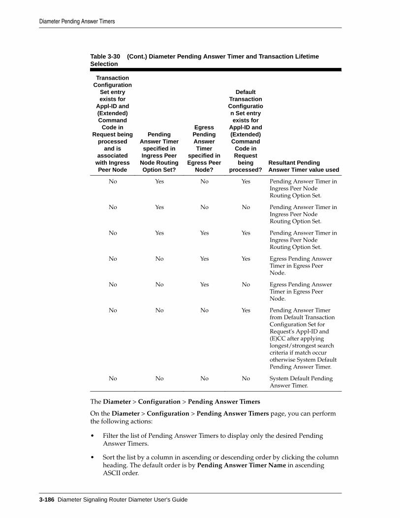
Table 3-30 (Cont.) Diameter Pending Answer Timer and Transaction LifetimeSelection
TransactionConfiguration
Set entryexists for
Appl-ID and(Extended)Command
Code inRequest being
processedand is
associatedwith IngressPeer Node
PendingAnswer Timerspecified inIngress Peer
Node RoutingOption Set?
EgressPendingAnswerTimer
specified inEgress Peer
Node?
DefaultTransactionConfiguration Set entryexists for
Appl-ID and(Extended)Command
Code inRequest
beingprocessed?
Resultant PendingAnswer Timer value used
No Yes No Yes Pending Answer Timer inIngress Peer NodeRouting Option Set.
No Yes No No Pending Answer Timer inIngress Peer NodeRouting Option Set.
No Yes Yes Yes Pending Answer Timer inIngress Peer NodeRouting Option Set.
No No Yes Yes Egress Pending AnswerTimer in Egress PeerNode.
No No Yes No Egress Pending AnswerTimer in Egress PeerNode.
No No No Yes Pending Answer Timerfrom Default TransactionConfiguration Set forRequest's Appl-ID and(E)CC after applyinglongest/strongest searchcriteria if match occurotherwise System DefaultPending Answer Timer.
No No No No System Default PendingAnswer Timer.
The Diameter > Configuration > Pending Answer Timers
On the Diameter > Configuration > Pending Answer Timers page, you can performthe following actions:
• Filter the list of Pending Answer Timers to display only the desired PendingAnswer Timers.
• Sort the list by a column in ascending or descending order by clicking the columnheading. The default order is by Pending Answer Timer Name in ascendingASCII order.
Diameter Pending Answer Timers
3-186 Diameter Signaling Router Diameter User's Guide

• Click Insert.
On the Diameter > Configuration > Pending Answer Timers [Insert] page, youcan add a new Pending Answer Timer.
The Diameter > Configuration > Pending Answer Timers [Insert] page does notopen if the maximum number of Pending Answer Timers (16) already exists in thesystem.
• Select a Pending Answer Timer in the list and click Edit.
On the Diameter > Configuration > Pending Answer Timers [Edit] page, you canedit the selected Pending Answer Timer.
If the selected Pending Answer Timer has been deleted by another user, theDiameter > Configuration > Pending Answer Timers [Edit] page does not open.
• Select a Pending Answer Timer in the list and click Delete. You can delete theselected Pending Answer Timer. You cannot delete the Default Pending AnswerTimer.
Diameter Pending Answer Timers elementsTable 3-31 describes the fields on the Pending Answer Timers View, Insert, and Editpages. Data Input Notes apply only to the Insert and Edit pages; the View page isread-only.
Table 3-31 Pending Answer Timers Elements
Field (* indicatesrequired field) Description Data Input Notes
* Pending AnswerTimer Name
Unique name of thePending Answer Timer.
Format: case-sensitive; alphanumericand underscore
Range: 1 - 32 characters; cannot startwith a digit and must contain at leastone alpha
* Pending AnswerTimer Value
The amount of timediameter waits for anAnswer from a upstreampeer after forwarding arequest.
Format: numeric
Range: 100 - 180000 ms
Default: 1000 ms
Adding a Pending Answer Timer
Use this task to create a new Pending Answer Timer. The fields are described in Diameter Pending Answer Timers elements.
1. Click Diameter > Configuration > Pending Answer Timers.
2. Click Insert.
3. Enter a unique name for the Pending Answer Timer in the Pending Answer TimerName field.
4. Set the Pending Answer Timer Value.
Diameter Pending Answer Timers
Configuring Diameter 3-187

5. Click OK, Apply, or Cancel.
Editing a Pending Answer Timer
Use this task to make changes to existing Pending Answer Timers.
The Pending Answer Timer Name cannot be changed.
1. Click Diameter > Configuration > Pending Answer Timers.
2. Select the Pending Answer Timer you want to edit.
3. Click Edit.
The page is initially populated with the current configured values for the selectedPending Answer Timer.
4. Update the relevant fields.
For more information about each field see Diameter Pending Answer Timerselements.
5. Click OK, Apply, or Cancel.
Deleting a Pending Answer Timer
Use this task to delete a Pending Answer Timer.
Note: A Pending Answer Timer cannot be deleted if it is referenced by eithera Peer Node or a Routing Option Set is referenced by Protected Networks. Italso cannot be deleted if it is associated with any Routing Option Set.
1. Click Diameter > Configuration > Pending Answer Timers.
2. Select the Pending Answer Timer you want to delete.
3. Click Delete.
A popup window appears to confirm the delete.
4. Click OK or Cancel.
Diameter Traffic Throttle PointsA Traffic Throttle Point (TTP) is the logical entity that contains the information that isrequired to perform (Peer Node, Application ID) ETR throttling. It contains user-defined configuration attributes and dynamic throttling information received fromupstream Peer Nodes via DOIC.
The RT-DB TTP table contains:
• User-defined TTP attributes
• DOIC throttling information received by way of DOIC AVPs
• Target ETR
• Diverted OTR
Diameter Traffic Throttle Points
3-188 Diameter Signaling Router Diameter User's Guide
When the routing application selects a Peer Node or Connection from a Route Group(or selects a Peer Node for implicit Routing), it checks if a TTP exists for the selectedPeer Node/Connection and Application ID in the Request message. If an active TTPexists, ETR throttling can be applied.
When routing a Request message, which has an associated Active TTP with DOICenabled, upstream Peer Nodes are notified that the node supports DOIC and providesa list of DOIC Abatement Algorithms. When an OC-Supported-Features AVP is sent ina Request message, it saves the TTP which triggered sending the DCA in the PTR.When an Answer response is received from a Peer Node and a non-NULL TTP issaved in the PTR, the application checks for DOIC AVPs that might contain a newoverload report (OLR) or contain changes to an existing overload report beingprocessed. Otherwise, the application does not check for DOIC AVPs in Answerresponses. Any valid requests from the upstream Peer Node to reduce traffic arestored in the TTP and immediately applied.
A TTP is required to manage the DSR Diameter Overload Indication Conveyance(DOIC) relationship between the routing application and the reacting nodes. TTPs:
• Control HostID/AppID pair scope
• Manage configuration parameters
• Track rate information
• Track their administrative, operational and a throttling status
Information collected at the TTP level for DOIC throttling can be used to improverouting decisions.
You can perform these tasks on an Active System OAM (SOAM).
You can perform the following actions for Traffic Throttle Points:
• Filter the list of Traffic Throttle Points to display only the desired Traffic ThrottlePoints.
• Sort the list by column contents in ascending or descending order by clicking thecolumn heading. The default order is by Traffic Throttle Points Name inascending ASCII order.
• Click Insert.
On the Traffic Throttle Points [Insert] page, you can add a new Traffic ThrottlePoint. See Adding Traffic Throttle Points.
If the maximum number of Traffic Throttle Points already exists in the system, anerror message displays.
• Select a Traffic Throttle Point Name in the list. Click Edit to display the TrafficThrottle Points [Edit] page and edit the selected Traffic Throttle Point.
See Editing Traffic Throttle Points.
If no Name is selected, Edit is disabled.
• Select a Traffic Throttle Point Name in the list and click Delete to remove theselected Traffic Throttle Point.
See Deleting Traffic Throttle Points.
Diameter Traffic Throttle Points
Configuring Diameter 3-189

Diameter Traffic Throttle Point elementsTable 3-32 describes the fields on the Traffic Throttle Points View, Insert, and Editpages. Data Input Notes apply only to the Insert and Edit pages; the View page isread-only.
Table 3-32 Traffic Throttle Point Elements
Field (* indicates arequired field) Description Data Input Notes
* Name The name of the Traffic ThrottlePoint.
Format: case-sensitive;alphanumeric and underscore
Range: 1 - 32 characters;cannot start with a digit andmust contain at least onealpha
Default: NA
* Peer Node The Egress Peer associated with thisDiameter Application ID and TrafficThrottle Point.
Format: List
Range: 1 - 32 characters;cannot start with a digit andmust contain at least onealpha
Default: NA
* Application ID The Diameter Application IDassociated with this Traffic ThrottlePoint.
Format: List
Range: 1 - 32 characters;cannot start with a digit andmust contain at least onealpha
Default: NA
TTP ConfigurationSet
The Traffic Throttle PointConfiguration Set that is associatedwith this Traffic Throttle Point.
Format: List
Range: 1 - 32 characters;cannot start with a digit andmust contain at least onealpha
Default: NA
* Max Loss PercentThreshold
The rate loss threshold where if thecurrent percent loss is greater than orequal to this value, requests shouldnot route to this Traffic Throttle Pointand should be diverted or discardedinstead.
Format: text box
Range: 1 - 100
Default: 100%
Alternate ImplicitRoute
Optional Route List to use forrouting messages to this Peer whenimplicit routing is invoked and theprimary route to the Peer isunavailable.
Format: List
Range: 1 - 100
Default: 100%
Diameter Traffic Throttle Points
3-190 Diameter Signaling Router Diameter User's Guide

Table 3-32 (Cont.) Traffic Throttle Point Elements
Field (* indicates arequired field) Description Data Input Notes
* Max ETR The maximum allowed EgressTransaction Rate for this TTP.
Format: text box
Range: 100 - 250000
Default: 6000
Adding Traffic Throttle Points
Use this task to create a new Traffic Throttle Point.
The fields are described in Diameter Traffic Throttle Point elements.
1. Click Diameter > Configuration > Traffic Throttle Points.
2. Click Insert.
3. Enter a unique name for the Traffic Throttle Point in the Name field.
4. Select or enter the element values.
5. Click OK, Apply, or Cancel.
Editing Traffic Throttle Points
Use this task to edit an existing Traffic Throttle Point.
When the Traffic Throttle Pointts page opens, the fields are populated with thecurrently configured values.
The Traffic Throttle Point Name cannot be edited.
The fields are described in Diameter Traffic Throttle Point elements.
1. Click Diameter > Configuration > Traffic Throttle Points.
2. Select the Traffic Throttle Point you want to edit.
3. Click Edit.
4. Update the relevant fields.
5. Click OK, Apply, or Cancel.
Deleting Traffic Throttle Points
Use this task to delete Traffic Throttle Points.
The default Traffic Throttle Point can be edited, but cannot be deleted.
1. Click Diameter > Configuration > Traffic Throttle Points.
2. Select the Traffic Throttle Point you want to delete.
3. Click Delete.
A popup window appears to confirm the delete.
Diameter Traffic Throttle Points
Configuring Diameter 3-191

4. Click OK or Cancel.
Diameter Traffic Throttle GroupsA Traffic Throttle Group (TTG) is a set of TTPs that share a common Application ID.A TTG is used for diverting transactions away from congested Route Groups (RGs).When a TTG is created and enabled for service, traffic loss is aggregated for the TTPsassigned to the TTG. Transactions are diverted away from congested RGs within a RLby assigning the TTG to a RG within a RL and assigning it a Maximum LossPercentage Threshold. When the routing application selects a RG from a RL that isassigned an active TTG, it determines whether the TTG's Current Traffic Loss exceedsthe RG's Maximum Loss Percentage Threshold. If the threshold is exceeded, that RG isbypassed for routing that transaction.
To make routing decisions at the Route List level it is necessary to aggregate some ofthe individual TTP-level data into data that represents the entire Route Group. Thissummary data is a Traffic Throttling Group (TTG). Only one parameter is summarizedin the TTG:
• The calculated Loss % of the TTG. This is the weighted (by Max ETR) average ofthe % loss in the available TTPs.
The routing application can use the congestion information in the TTGs to skip RouteGroups in the Route List that do not meet threshold criteria for their congestion status.A typical use for skipping congested Route Groups is to prevent a routing applicationthat cannot handle traffic due to congestion from sending that traffic to a mate routingapplication that is already equally overloaded.
Note: Only TTGs that are configured locally can be administratively enabledor disabled by an SOAM. A Shared TTG owned by another site must bedisabled at the owning site.
You can perform these tasks on an Active System OAM (SOAM).
You can perform the following actions for Traffic Throttle Groups:
• Filter the list of Traffic Throttle Groups to display only the desired Traffic ThrottleGroups.
• Sort the list by column contents in ascending or descending order by clicking thecolumn heading. The default order is by Traffic Throttle Groups Name inascending ASCII order.
• Click Insert.
On the Traffic Throttle Groups [Insert] page, you can add a new Traffic ThrottleGroup. See Adding Traffic Throttle Groups.
If the maximum number of Traffic Throttle Groups already exists in the system, anerror message displays.
• Select a Traffic Throttle Group Name in the list. Click Edit to display the TrafficThrottle Groups [Edit] page and edit the selected Traffic Throttle Group.
See Editing Traffic Throttle Groups.
If no Name is selected, Edit is disabled.
Diameter Traffic Throttle Groups
3-192 Diameter Signaling Router Diameter User's Guide

• Select a Traffic Throttle Group Name in the list and click Delete to remove theselected Traffic Throttle Group.
Diameter Traffic Throttle Groups elementsTable 3-33 describes the fields on the Traffic Throttle Groups View, Insert, and Editpages. Data Input Notes apply only to the Insert and Edit pages; the View page isread-only.
Table 3-33 Traffic Throttle Groups Elements
Field (* indicatesa required field) Description Data Input Notes
* Name A name of the TrafficThrottle Group
Format: text box
1 - 32 characters; cannot start with a digitand must contain at least one alpha
Default: NA
* TTP TTPs associated with thisTTG
Format: List
Range: NA
Default: NA
* Application ID The Diameter Application IDassociated with this TrafficThrottle Group
Format: List
Range: 1 - 32 characters; cannot startwith a digit and must contain at least onealpha
Default: NA
Adding Traffic Throttle Groups
Use this task to create a new Traffic Throttle Group.
The fields are described in Diameter Traffic Throttle Groups elements.
Note: When you select an Application Id to the Traffic Throttle Group, youare only allowed to select the TTP whose application ID matches theapplication ID that of Traffic Throttle Group.
1. Click Diameter > Configuration > Traffic Throttle Groups.
2. Click Insert.
3. Enter a unique name in the Name field.
4. Select or enter the element values.
5. Click OK, Apply, or Cancel.
If OK or Apply is clicked and any of the following conditions exist, then an errormessage appears:
• Any required field is empty (no value was entered).
Diameter Traffic Throttle Groups
Configuring Diameter 3-193

• The value in any field is not valid or is out of range.
• The Name is not unique; it already exists in the system.
• The maximum number of TTGs has already been configured.
Editing Traffic Throttle Groups
Use this task to edit an existing Traffic Throttle Group.
When the Traffic Throttle Groups page opens, the fields are populated with thecurrently configured values.
The Traffic Throttle Point Groups Name cannot be edited.
The fields are described in Diameter Traffic Throttle Groups elements.
1. Click Diameter > Configuration > Traffic Throttle Groups.
2. Select the Traffic Throttle Point Group to edit.
3. Click Edit.
4. Update the relevant fields.
5. Click OK, Apply, or Cancel.
If OK or Apply is clicked and any of the following conditions exist, then an errormessage appears:
• The selected Traffic Throttle Group no longer exists; it has been deleted byanother user.
• Any field is empty (no value was entered).
• If you attempt to update a TTG and mark it as shared, but the NOAM is notaccessible.
• If you attempt to mark the shared TTG to non-shared when it is already beingused by a Route List configured on another DSR within this network.
• The value in any field is not valid or is out of range.
Deleting Traffic Throttle Groups
Use this task to delete Traffic Throttle Groups.
1. Click Diameter > Configuration > Traffic Throttle Groups.
2. Select the Traffic Throttle Group you want to delete.
3. Click Delete.
A popup window appears to confirm the delete.
4. Click OK or Cancel.
Diameter Traffic Throttle Groups
3-194 Diameter Signaling Router Diameter User's Guide

Diameter AVP Removal ListsThe AVP Removal function allows you to specify which AVPs to remove. You can alsoexclude AVPs on a specific Peer by specifying which AVPs and in what type ofmessage (request or answer).
You can perform these tasks on an Active System OAM (SOAM).
You can perform the following actions for AVP Removal Lists:
• Filter the list of AVP Removal Lists to display only the desired AVP Removal Lists.
• Sort the list by column contents in ascending or descending order by clicking thecolumn heading. The default order is by AVP Removal Lists in ascending ASCIIorder.
• Click Insert.
On the AVP Removal Lists [Insert] page, you can add a new AVP Removal List.See Adding AVP Removal Lists.
If the maximum number of AVP Removal Lists already exists in the system, anerror message displays.
• Select a AVP Removal List Name in the list. Click Edit to display the AVPRemoval Lists [Edit] page and edit the selected AVP Removal List.
See Editing AVP Removal Lists.
If no Name is selected, Edit is disabled.
• Select a AVP Removal List Name in the list and click Delete to remove theselected AVP Removal List.
The default AVP Removal List can be edited, but cannot be deleted. See DeletingAVP Removal Lists.
Diameter AVP Removal Lists elementsTable 3-34 describes the fields on the Diameter > AVP Removal Lists > View, Insert,and Edit pages. Data Input Notes apply only to the Insert and Edit pages; the Viewpage is read-only.
Table 3-34 AVP Removal Lists Elements
Field (* indicates arequired field) Description Data Input Notes
* Name A name of the AVP Removal List Format: text box
Range: 1 - 32 characters; cannotstart with a digit and mustcontain at least one alpha
Default: NA
Diameter AVP Removal Lists
Configuring Diameter 3-195

Table 3-34 (Cont.) AVP Removal Lists Elements
Field (* indicates arequired field) Description Data Input Notes
* Direction Defines whether the AVP removaloccurs when the message isreceived from the peer node orwhether the AVP removal occurswhen the message, or both, is sentto the peer node
Format: List
Range: Ingress Only, EgressOnly, Egress & Ingress
Default: Ingress Only
* Message Type Defines the type of message thatAVP removal is applied to
Format: List
Range: Request Only, AnswerOnly, Answer & Request
Default: Request Only
AVP Removal List A list of one or more AVPs to beremoved from messages
Format: multiple fields
Range: A list of one or moreAVPs to be removed fromrequests.
Default: NA
AVP Code The 32-bit AVP Code, combinedwith the Vendor-ID field, identifiesthe attribute uniquely
Format: text box
Range: 32-bit Unsigned Integer
Default: NA
AVP Name User-defined name associated withthe AVP Code
Format: text box
Setting a value on this field isoption; informational only.
Vendor ID Vendors are allowed to add AVPs tothe Diameter specification. Vendor-specific AVPs contains a Vendor-IDfield
Format: text box
Range: 32-bit Unsigned Integer
Default: 0
Vendor Name User-defined name associated withthe Vendor-ID value
Format: text box
Setting a value on this field isoption; informational only.
Adding AVP Removal Lists
Use this task to create a new AVP Removal List.
The fields are described in Diameter AVP Removal Lists elements.
1. Click Diameter > Configuration > AVP Removal Lists.
2. Click Insert.
3. Enter a unique name in the Name field.
4. Select or enter the element values.
5. Click OK, Apply, or Cancel.
Diameter AVP Removal Lists
3-196 Diameter Signaling Router Diameter User's Guide

If OK or Apply is clicked and any of the following conditions exist, then an errormessage appears:
• Any required field is empty (no value was entered).
• The value in any field is not valid or is out of range.
• The AVP Removal Lists Name is not unique; it already exists in the system.
Editing AVP Removal Lists
Use this task to edit an existing AVP Removal List.
When the AVP Removal Lists page opens, the fields are populated with the currentlyconfigured values.
The AVP Removal List Name cannot be edited.
The fields are described in Diameter AVP Removal Lists elements
1. Click Diameter > Configuration > AVP Removal Lists.
2. Select the AVP Removal List you want to edit.
3. Click Edit.
4. Update the relevant fields.
5. Click OK, Apply, or Cancel.
If OK or Apply is clicked and any of the following conditions exist, then an errormessage appears:
• The selected AVP Removal List no longer exists; it has been deleted by anotheruser.
• Any field is empty (no value was entered).
• The value in any field is not valid or is out of range.
Deleting AVP Removal Lists
Use this task to delete AVP Removal Lists.
1. Click Diameter > Configuration > AVP Removal Lists.
2. Select the AVP Removal List you want to delete.
3. Click Delete.
A popup window appears to confirm the delete.
4. Click OK or Cancel.
If OK is clicked and the selected AVP Removal List is referenced by any peer node,then an error message appears and the AVP Removal Lists are not deleted.
Diameter Application Priority OptionsThis feature allows DSR to support Diameter Routing Message Priority (DRMP).DRMP allows Diameter to include DRMP Attribute-Value Pair (AVP) in Diameter
Diameter Application Priority Options
Configuring Diameter 3-197

messages to specify the relative priority of the Diameter message on a scale of 0 to 15where priority value zero is specified as the highest priority and priority value 15 isthe lowest priority.
When a Diameter node which supports DRMP receives a message containing a DRMPAVP, it is required to make any Diameter overload throttling decisions based upon therelative DRMP message priority. For example, lower priority messages are throttledbefore higher priority messages. The DRMP AVP can be appended to Request andAnswer messages. A DRMP AVP appended to a Request message represents thepriority of all messages associated with the end-to-end Diameter transaction. ADiameter endpoint node can optionally modify the priority of the Answer message forthat transaction by appending a DRMP AVP.
Diameter Application Priority Options can be viewed and set on the Diameter >Configuration > Application Priority Options page.
You can perform these tasks on an active System OAM (SOAM).
On the Diameter > Configuration > Application Priority Options page, you can:
• Filter the list of Application Priority Options to display only the desiredApplications.
• Sort the list by a column in ascending or descending order by clicking the columnheading. The default order is by Application Name in ascending ASCII order.
• Click Insert.
On the Application Priority Options [Insert] page, you can add a new Application.See Adding Application Priority Options.
• Select an Application in the list and click Edit to display the Application PriorityOptions [Edit] page and edit the options associated with the selected Application.See Editing Application Priority Options.
• Select an Application in the list and click Delete to remove the selectedApplication. See Deleting Application Priority Options.
Diameter Application Priority Options elementsTable 3-35 describes the fields on the Application Priority Options page.
Table 3-35 Application Priority Options Elements
Field Description Data Input Notes
* Application Name Diameter Application Name. Format: field
Range: none
Default: 60000
* Application ID Identifies a specific Diameter Application IDvalue associated with the DiameterApplication Name.
Format: option
Range: enabled,disabled
Default: Disabled
Diameter Application Priority Options
3-198 Diameter Signaling Router Diameter User's Guide

Table 3-35 (Cont.) Application Priority Options Elements
Field Description Data Input Notes
NGN-PS 3GPP AVPAdmin State
Defines if the NGN-PS feature is enabled forthe selected Diameter Application.
Format: option
Range: enabled,disabled
Default: Disabled
NGN-PS DRMP AVPAdmin State
Defines if a Diameter message can be taggedas invioable when DRMP AVP = 0 isreceived in a message
Format: option
Range: enabled,disabled
Default: Disabled
Request DRMP AVPAdmin State
Defines if DRMP AVPS in normal Requestmessages are honored for this Application.
Format: option
Range: enabled,disabled
Default: Disabled
Answer DRMP AVPAdmin State
Defines if DRMP AVPS in Answer messagesassociated with non-NGN-PS transactionsare honored for this Application.
Format: option
Range: enabled,disabled
Default: Disabled
Adding Application Priority Options
Use this task to add a new application option to the priority list.
The fields are described in Diameter Application Priority Options elements.
1. Click Diameter > Configuration > Application Priority Options.
2. Click Insert.
3. Select the Application ID.
The Application Name corresponding with the Application ID is automaticallypopulated.
4. Change any options for the Application.
5. Click Apply or Cancel.
Editing Application Priority Options
Use this task to edit an existing Application Priority Options.
When the Application Priority Options page opens, the fields are populated with thecurrently configured values.
You cannot edit greyed out fields on the Application Priority Options tabs.
The fields are described in Diameter Application Priority Options elements.
1. Click Diameter > Configuration > Application Priority Options.
Diameter Application Priority Options
Configuring Diameter 3-199

2. Select the Application row you want to edit.
3. Click Edit.
4. Change the options for the Application you selected.
5. Click OK, Apply, or Cancel.
Deleting Application Priority Options
Use this task to delete an Application from the priority options.
When the Application Priority Options page opens, the fields are populated with thecurrently configured values.
You cannot edit greyed out fields on the Application Priority Options tabs.
The fields are described in Diameter Application Priority Options elements.
1. Click Diameter > Configuration > Application Priority Options.
2. Select the Application row you want to delete.
3. Click Delete.
A window appears to confirm the delete.
4. Click OK or Cancel.
Diameter System OptionsDiameter System Options can be viewed and set on the Diameter > Configuration >System Options page.
You can perform these tasks on an active System OAM (SOAM).
Note: See Next Generation Network Priority Service (NGN-PS) for anoverview of NGN-PS.
On the Diameter > Configuration > System Options page, you can:
• Modify current system options values, and click Apply to save the changes.
• Click Cancel to remove and not save any changes you have made.
• Click the General Options, Alarm Threshold Options, or Message CopyOptions, Radius UDP Options, Peer Discovery Options, or Priority Options tabto access those options.
Diameter System Options elementsTable 3-36 describes the fields on the System Options page.
Table 3-36 System Options Elements
Field Description Data Input Notes
General Options
Diameter System Options
3-200 Diameter Signaling Router Diameter User's Guide

Table 3-36 (Cont.) System Options Elements
Field Description Data Input Notes
Engineered MessageSize Allowed
Engineered message size of a diametermessage (in bytes) allowed by theapplication.
This field is read-only; it cannot be changed.
Format: Field
Range: none
Default: 60000
Interval ICMP pingof all peer next-hops
If checked, an ICMP ping echo is sent to thenext-hop of every remote peer every 2minutes. This is useful for keeping switchaddress tables up-to-date.
Format: Checkbox
Range: Checked(enabled), not checked(disabled)
Default: Disabled
IPFE ConnectionReserved IngressMPS Scaling
Percentage of DA-MP engineered ingressMPS used by each DA-MP when validatingthe reserved ingress MPS for a newlyreceived floating IPFE connection. A newlyreceived floating IPFE connection is rejectedif the total connection reserved ingress MPSfor fixed and already established floatingIPFE connections would exceed the DA-MP's engineered ingress MPS, scaled by thisvalue.
This field is view-only; it cannot be user-configured.
Format: Field
Range: 30-100 percent
Default: 50 percent
Redirect AnswerProcessing Enabled
If checked, redirect notification responseprocessing is enabled. If unchecked, redirectnotification response processing is disabled.If disabled, redirect notification responsesare passed through to the downstream peer.
Redirect notifications are processed asfollows:• Redirect notifications with redirect-
host-usage equal to do not cache areprocessed.
• Redirect notifications with no redirect-host-usage AVP are processed.
• Redirect notifications with redirect-host-usage not equal to do not cache areforwarded to the downstream peer.
Format: Checkbox
Range: Checked(enabled), not checked(disabled)
Default: none
Diameter System Options
Configuring Diameter 3-201

Table 3-36 (Cont.) System Options Elements
Field Description Data Input Notes
Redirect ApplicationRoute Table
Application route table instance used toprocess a redirected request.
Note: If not configured, ART processing isskipped, and if configured, the ART issearched with the content of the redirectrequest message, similar to an ingressrequest.
Format: List
Range: none
Default: none
Redirect Peer RouteTable
Peer route table instance used to process aredirected request.
Note: If not configured, the PRT selectionprocess is identical to the ingress request.
Format: List
Range: none
Default: none
Encode FQDN InLower Case
Determines whether or not FQDNs shouldbe encoded as configured or in all lower-case.
Format: Options
Range: Yes, No
Default: Yes
* Excessive RerouteOnset Threshold
Excessive reroute alarm is raised whenpercentage of the total rerouted messagesdue to answer response and/or answertimeout to the total requests forwardedexceeds the onset threshold value.
Format: Field
Range: 1-100
Default: 20
* Excessive RerouteAbatement Threshold
Excessive reroute alarm is cleared whenpercentage of the total rerouted messagesdue to answer response and/or answertimeout to the total requests forwarded isless than this abatement threshold forconfigured abatement time.
The excessive reroute abatement thresholdfield value must be less than excessivereroute onset threshold field value.
Format: Field
Range: 0-99 percent
Default: 15 percent
Discard Policy The order of priority and/or color-basedtraffic segments to consider whendetermining discard candidates for theapplication of treatment during Congestionprocessing.
Format: List
Range: Color WithinPriority, PriorityWithin Color, PriorityOnly
Default: Priority Only
Diameter System Options
3-202 Diameter Signaling Router Diameter User's Guide

Table 3-36 (Cont.) System Options Elements
Field Description Data Input Notes
ETG Mode Defines the type of message throttlingsupported when routing Request messagesto connections associated with ETGs.
Threshold - Threshold Mode is legacy mode,which configures the congestion level forETGs and enforce the Requests based oncongestion level of ETG.
Limit - Limit Mode shapes the egressmessage rate according to the maximummessage and pending transaction rate, thesystem discard policy, and the current mix ofrequests by message color and priority.
Format: List
Range: Threshold,Limit
Default: Threshold
Alarm Threshold Options
* Available AlarmBudget
The engineered combined total supportedalarms allowed for Fixed Connection,floating IPFE Connection, Peer Node, andRoute List managed objects.
The value displayed on the System Optionscreen is 3,000 minus the default values foreach threshold field.
Format: Field
Range: 0-3000
Default: 3000
* Fixed ConnectionFailure MajorAggregation AlarmThreshold
Major threshold for fixed connection failurealarm aggregation per DA-MP. The availablealarm budget is decremented by this valuemultiplied by the number of configured DA-MPs.
Format: FieldRange: 1 to AvailableAlarm Budget
Default: 100
* Fixed ConnectionFailure CriticalAggregation AlarmThreshold
Critical threshold for fixed connectionfailure alarm aggregation per DA-MP. Thisvalue is not counted against the availablealarm budget.
Format: Field
Range: 0 to AvailableAlarm Budget
Default: 200
* Floating IPFEConnection FailureMajor AggregationAlarm Threshold
Major threshold for aggregated floating IPFEconnection alarms per NE. The availablealarm budget is decrement by this value.
Format: Field
Range: 1 to AvailableAlarm Budget
Default: 100
* Floating IPFEConnection FailureCritical AggregationAlarm Threshold
Critical threshold for aggregated floatingIPFE connection alarms per NE. This value isnot counted against the available alarmbudget.
Format: FieldRange: 0 to AvailableAlarm Budget
Default: 100
* Peer Node FailureCritical AggregationAlarm Threshold
Critical threshold for aggregated peer nodefailure alarms per NE. The available alarmbudgets decremented by this value
Format: Field
Range: 1 to AvailableAlarm Budget
Default: 600
Diameter System Options
Configuring Diameter 3-203
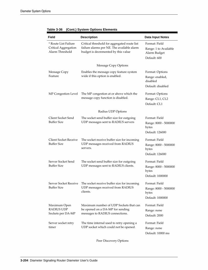
Table 3-36 (Cont.) System Options Elements
Field Description Data Input Notes
* Route List FailureCritical AggregationAlarm Threshold
Critical threshold for aggregated route listfailure alarms per NE. The available alarmbudget is decremented by this value
Format: Field
Range: 1 to AvailableAlarm Budget
Default: 600
Message Copy Options
Message CopyFeature
Enables the message copy feature systemwide if this option is enabled.
Format: Options
Range: enabled,disabled
Default: disabled
MP Congestion Level The MP congestion at or above which themessage copy function is disabled.
Format: Options
Range: CL1, CL2
Default: CL1
Radius UDP Options
Client Socket SendBuffer Size
The socket send buffer size for outgoingUDP messages sent to RADIUS servers
Format: Field
Range: 8000 - 5000000bytes
Default: 126000
Client Socket ReceiveBuffer Size
The socket receive buffer size for incomingUDP messages received from RADIUSservers.
Format: Field
Range: 8000 - 5000000bytes
Default: 126000
Server Socket SendBuffer Size
The socket send buffer size for outgoingUDP messages sent to RADIUS clients.
Format: Field
Range: 8000 - 5000000bytes
Default: 1000000
Server Socket ReceiveBuffer Size
The socket receive buffer size for incomingUDP messages received from RADIUSclients.
Format: Field
Range: 8000 - 5000000bytes
Default: 1000000
Maximum OpenRADIUS UDPSockets per DA-MP
Maximum number of UDP Sockets that canbe opened on a DA-MP for sendingmessages to RADIUS connections.
Format: Field
Range: none
Default: 2000
Server socket retrytimer
The time internal used to retry opening aUDP socket which could not be opened.
Format: Field
Range: none
Default: 10000 ms
Peer Discovery Options
Diameter System Options
3-204 Diameter Signaling Router Diameter User's Guide

Table 3-36 (Cont.) System Options Elements
Field Description Data Input Notes
Realm ExpirationMinor Alarm SetTime
Time, in hours before the expiration of adynamically-discovered realm, at which aminor alarm is raised to indicate that therealm expiration is approaching. A value ofzero means no minor alarm is raised to alertof the pending realm expiration.
Format: Field
Range: 0 - 168 hours
Default: 6
Realm ExpirationMajor Alarm SetTime
Time, in hours before the expiration of adynamically-discovered realm, at which amajor alarm is raised to indicate that therealm expiration is approaching. A value ofzero means no major alarm is raised to alertof the pending realm expiration.
Format: Field
Range: 0 - 167 hours
Default: 1
Priority Options
16 Priority AdminState
Defines whether the DSR supports 15 or 5message priorities. When set to Disabled,DSR supports 5 internal message priorities.When set to Enabled, the discard policy isset to Policing Mode.
Format: Options
Range: enabled,disabled
Default: disabled
NGN-PS AdminState
Defines whether the NGN-PS is enabled ornot. When set to Disabled, DSR does notprovide NGN-PS treatment to any messages.
Format: Options
Range: enabled,disabled
Default: disabled
Answer PriorityMode
Defines which method to be used forassigning priority to Answer messages. IfHighest Priority, Answers will have highestpriority (or 1 lower than Highest when'NGN-PS Admin State' is set to Enabled.When this method is selected, DRMP AVPsin Answer messages are ignored.
If Request Priority, Answers have the samepriority as Requests.
Format: Options
Range: HighestPriority, RequestPriority
Default: HighestPriority
Diameter System Options
Configuring Diameter 3-205
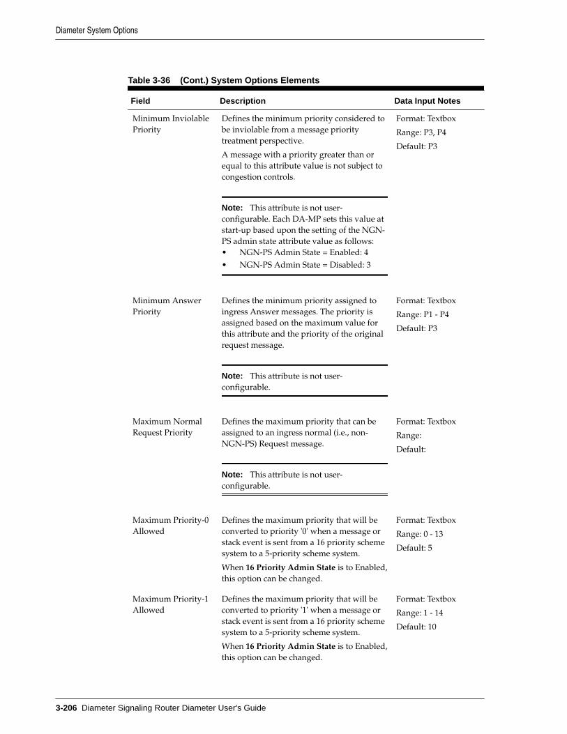
Table 3-36 (Cont.) System Options Elements
Field Description Data Input Notes
Minimum InviolablePriority
Defines the minimum priority considered tobe inviolable from a message prioritytreatment perspective.
A message with a priority greater than orequal to this attribute value is not subject tocongestion controls.
Note: This attribute is not user-configurable. Each DA-MP sets this value atstart-up based upon the setting of the NGN-PS admin state attribute value as follows:• NGN-PS Admin State = Enabled: 4• NGN-PS Admin State = Disabled: 3
Format: Textbox
Range: P3, P4
Default: P3
Minimum AnswerPriority
Defines the minimum priority assigned toingress Answer messages. The priority isassigned based on the maximum value forthis attribute and the priority of the originalrequest message.
Note: This attribute is not user-configurable.
Format: Textbox
Range: P1 - P4
Default: P3
Maximum NormalRequest Priority
Defines the maximum priority that can beassigned to an ingress normal (i.e., non-NGN-PS) Request message.
Note: This attribute is not user-configurable.
Format: Textbox
Range:
Default:
Maximum Priority-0Allowed
Defines the maximum priority that will beconverted to priority '0' when a message orstack event is sent from a 16 priority schemesystem to a 5-priority scheme system.
When 16 Priority Admin State is to Enabled,this option can be changed.
Format: Textbox
Range: 0 - 13
Default: 5
Maximum Priority-1Allowed
Defines the maximum priority that will beconverted to priority '1' when a message orstack event is sent from a 16 priority schemesystem to a 5-priority scheme system.
When 16 Priority Admin State is to Enabled,this option can be changed.
Format: Textbox
Range: 1 - 14
Default: 10
Diameter System Options
3-206 Diameter Signaling Router Diameter User's Guide

Table 3-36 (Cont.) System Options Elements
Field Description Data Input Notes
Maximum Priority-2Allowed
Defines the maximum priority that will beconverted to priority '2' when a message orstack event is sent from a 16 priority schemesystem to a 5-priority scheme system.
When 16 Priority Admin State is to Enabled,this option can be changed.
Format: Textbox
Range: 2 - 15
Default: 14
NGN-PS MaximumMessage Rate Percent
Defines the maximum ingress NGN-PSmessage that is supported (a percentage ofthe DA-MP message rate). NGN-PS traffic inexcess of this rate, is not considered to beinviolable.
Format: Field
Range: 1 - 15
Default: 3
NGN-PS Gx
NGN-PS Gx AdminState
Defines whether the NGN-PS is enabled ornot for Gx messages. When set to Disabled,DSR does not provide NGN-PS treatment toGx messages.
Note: This attribute is superseded by theNGN-PS Admin State attribute. If NGN-PSAdmin State is set to Disabled, no Gxmessages are provided NGN-PS treatmentregardless of the setting of this attribute.
Format: Options
Range: enabled,disabled
Default: disabled
NGN-PS Gx ARP Sets the priority level contained in Gxmessages in ARP AVP that can be treated asNGN-PS messages.
Note: You can configure a maximum of 5priority levels.
Format: Field
Range: 1-5
Default: none
NGN-PS Gx AdvancePriority Type
Determines the Access Network priorityprovided to an NGN-PS Subscribed UE. Thisaffects the tagging of Gx CCR messages forNGN-PS treatment.
Format: Options
Range: None,Advance Priority SPR,and Advance PriorityHSS
Default: none
NGN-PS Rx
Diameter System Options
Configuring Diameter 3-207

Table 3-36 (Cont.) System Options Elements
Field Description Data Input Notes
NGN-PS Rx AdminState
Defines whether the NGN-PS feature isenabled or not for Rx messages. When thisattribute is set to Disabled, DSR does notprovide NGN-PS treatment to Rx messages.
Note: This attribute is superseded by theNGN-PS Admin State attribute. If NGN-PSAdmin State is set to Disabled, no Rxmessages are provided NGN-PS treatmentregardless of the setting of this attribute.
Format: Options
Range: enabled,disabled
Default: disabled
NGN-PS Rx MPSAVP Value
A Rx AAR message is considered a NGN-PSmessage candidate if it contains a MPS-Identifier AVP whose value is identical tothis string.
Format: Field
Range: none
Default: none
NGN-PS Cx/Dx
NGN-PS Cx/DxAdmin State
Defines whether the NGN-PS feature isenabled or not for Cx/Dx messages. Whenthis attribute is set to Disabled, DSR doesnot provide NGN-PS treatment to Cx/Dxmessages.
Note: This attribute is superseded by theNGN-PS Admin State attribute. If NGN-PSAdmin State is set to Disabled, no Cx/Dxmessages are provided NGN-PS treatmentregardless of the setting of this attribute.
Format: Options
Range: enabled,disabled
Default: disabled
NGN-PS Dh/Sh
NGN-PS Dh/ShAdmin State
Defines whether the NGN-PS feature isenabled or not for Dh/Sh messages. Whenthis attribute is set to Disabled, DSR doesnot provide NGN-PS treatment to Dh/Shmessages.
Note: This attribute is superseded by theNGN-PS Admin State attribute. If NGN-PSAdmin State is set to Disabled, no Dh/Shmessages are provided NGN-PS treatmentregardless of the setting of this attribute.
Format: options
Range: enabled,disabled
Default: disabled
Diameter System Options
3-208 Diameter Signaling Router Diameter User's Guide

Editing System Options
Use this task to edit an existing System Options.
When the System Options page opens, the fields are populated with the currentlyconfigured values.
You cannot edit greyed out fields cannot be edited on the System Options tabs.
The fields are described in Diameter System Options elements.
1. Click Diameter > Configuration > System Options.
2. Select the System Options tab you want to edit.
3. Update the relevant fields.
4. Click Apply or Cancel.
Diameter DNS OptionsThe DNS Options page allows you to set the length of time the application waits forqueries from the Domain Name System (DNS) server. You can also provide an IPaddress for the primary and secondary DNS server.
You can perform these tasks on an Active System OAM (SOAM).
To open the Diameter > Configuration > DNS Options page, select Diameter >Configuration > DNS Options.
The DNS Options fields are described in Diameter DNS Options elements.
On the Diameter > Configuration > DNS Options page, you can set the DNS Optionsvalues and click:
• Apply to save the changes
• Cancel to remove and not save any changes
If Apply is clicked and any of the following conditions exist, then an error messageappears:
• The DNS Query Duration Timer field has no value
• The DNS Query Duration Timer value is not valid
• The Primary or Secondary DNS Server IP Address field value is not valid
• The Secondary DNS Server IP Address field has a value, but the Primary DNSServer IP Address field is blank
• The Primary DNS Server IP Address field is blank and there is at least oneInitiator Connection without a Peer IP Address
Diameter DNS Options elementsTable 3-37 describes the fields on the Diameter > Configuration > DNS Options page.
Diameter DNS Options
Configuring Diameter 3-209

Table 3-37 DNS Options Elements
Field (* indicatesrequired field) Description Data Input Notes
Primary DNS ServerIP Address
IP address of the primary DNS server. Format: valid IPaddress
Secondary DNSServer IP Address
IP address of the secondary DNS server. Format: valid IPaddress
* DNS QueryDuration Timer
The amount of time the application waits forqueries to the DNS servers (in seconds).
Format: numeric
Range: 1 - 4
Default: 2
Editing DNS Options
Use this task to edit an existing DNS Options.
The fields are described in Diameter DNS Options elements.
1. Click Diameter > Configuration > DNS Options.
2. Update the relevant fields.
3. Click Apply or Cancel.
If Apply is clicked and any of the following conditions exist, then an error messageappears:
• The selected Traffic Throttle Point Configuration Set no longer exists; it hasbeen deleted by another user.
• Any field is empty (no value was entered).
• The value in any field is not valid or is out of range.
Diameter Peer DiscoveryPeer Discovery (also know as Dynamic Peer Discovery [DPD]) allows an applicationto discover remote hosts within user-defined Realms and configures all required GUIelements for successful routing of diameter traffic between the signalling router andthose remote hosts. This configuration is dynamic, and no user input is required at thetime the routing GUI elements are created.
You can perform these tasks on an Active System OAM (SOAM).
In general, Peer Discovery configuration order is as follows:
• Peer Node
• CEXCfgSet
• Connection
• Route Group
• Route List
Diameter Peer Discovery
3-210 Diameter Signaling Router Diameter User's Guide

Note: This order is not guaranteed; in some configurations, variationsassociated with a particular Application ID could alter this order.
For a Diameter router to route messages properly, target entity information is required.This includes the network entity IP address, the transport protocol and ports that ituses to communicate, and what Diameter application it supports. This informationabout a remote host is managed by the Peer Node configuration. See Diameter PeerNodes.
After a Peer Node is defined, one or more IP connections must be defined so thatpackets can be routed between the diameter router and the Peer Node. Connectionsidentify the parameters that define an IP connection, and the CEX Configuration Setdefines the Diameter Application IDs that the diameter router is authorized to sendand receive over the connection. When the diameter signalling router and a diameterpeer initially establish an IP connection between themselves, they negotiate thediameter services that can be carried on that IP connection. That negotiation involvesthe exchange of supported Diameter Application IDs.
For load balancing and redundancy purposes, multiple Peer Nodes that share certaincharacteristics can be grouped together into Route Groups. The diameter router usesthe routing algorithms of the configured Route Groups and Route Lists whendetermining on which Connection to send a particular Diameter message.
Peer Discovery allows you to work with:
• Realms (see Realms)
• DNS Sets (see DNS Sets)
• Discovery Attributes (see Discovery Attributes)
RealmsThe Diameter > Configuration > Peer Discovery > Realms page displays the RealmsGUI page.
See Realms Overview for more information.
On the Diameter > Configuration > Peer Discovery > Realms page, you can performthe following actions:
• Filter the list of Realms to display only the desired Realms.
• Sort the list by a column, in ascending or descending order by clicking the columnheading. The default order is by Realm Name in ascending ASCII order.
• Click Insert.
On the Realms [Insert] page, you can add a new Realm. See Adding Realms.
If the maximum number of Realms already exists in the system, an error messagedisplays.
• Select a Realm Name in the list and click Edit to display the Realms[Edit] pageand edit the selected Realm. See Editing Realms.
• Select a Realm Name and click Delete to remove the selected Realm Name. See Deleting Realms.
Diameter Peer Discovery
Configuring Diameter 3-211

Realms Overview
A realm is an internet domain whose Fully-Qualified Domain Names (FQDNs)typically all share a domain designation. For example, example.com could be a Realmname, and the addressable hosts in the Realm would have names likehost1.example.com, host2.subdomain1.example.com, and so on.
In the diameter signaling space, an operator creates a realm name, then assignsFQDNs to all of the computers that transact diameter traffic. The number of computersin the Diameter Realm depends on the number and type of diameter services theoperator intends to support, as well as the expected volume of diameter traffic.Typically, load-sharing and redundancy are major factors governing the internalorganization of a Diameter Realm.
The dynamic discovery of remote hosts is always undertaken within a single realm.Many realms can be discovered dynamically, but the discovery of one realm is aprocess independent of that for all other realms that are to be discovered.
Configuring Routing Information
Diameter signaling routers establish connections to Diameter Peers and routeDiameter traffic to those Peers only after all of the necessary routing configurationchanges are manually entered into the DSR. Specific configuration changes are user-initiated, either through the GUI or by importing configuration changes by way ofBulk Import/Export (BIE).See the Bulk Import and Export information in DiameterCommon User's Guide. These configuration changes are static changes because onceentered; they remain in place until you take action to modify or delete them.
DPD implies dynamic configuration changes. Instead of user-specified routingconfiguration changes, the diameter signaling router learns about remote hosts anddynamically makes the necessary routing configuration changes. The informationdiscovered about remote hosts residing in any Diameter Realm has a defined lifetime,a Time To Live (TTL). Therefore, realm-specific routing configuration madedynamically to a diameter signaling router also has a defined lifetime, and undercertain circumstances, this dynamic routing configuration is automatically destroyed,and the Realm can be re-discovered; all of this occurs without user interaction.Dynamic describes these diameter signaling router-initiated routing configurationchanges that are created and destroyed over time.
You should understand the difference between static and dynamic configuration withrespect to DPD.
• Static configuration is necessary to set up and execute DPD
• Dynamic configuration results from a Diameter Realm having been successfullydiscovered
DPD setup and execution requires static configuration. The name of the Realm to bediscovered, the DNS server(s) that are used to get information about that Realm, andthe necessary additional discovery attributes are all statically configured by a user toestablish the input parameters governing the discovery of a particular DiameterRealm. Assuming the discovery algorithm is successful, at least one Peer Node and theConnection(s), CEX Configuration Set(s), Route Group(s), and Route List(s) requiredto properly route Diameter traffic to the Peer Node(s) are dynamically added to therouting configuration.
Diameter Peer Discovery
3-212 Diameter Signaling Router Diameter User's Guide

Creating Discoverable Realms
Any Diameter Realm that is to be discovered must first be made discoverable by aDNS administrator who has knowledge of the hosts within the Realm and the servicesthey provide. The Realm's DNS administrator must set up a DNS zone file thatcontains all of the information about the Realm that the administrator wants to makepublic. The DNS zone file resides on any of the Realm's DNS servers that are expectedto be queried about Realm services.
The routing application discovers the Realm by sending questions (DNS requests) tothe Realm's DNS server or servers. Depending on the answers, the routing applicationdynamically updates the configuration. These answers are in the form of DNSResource Records (RRs).
DPD relies on three DNS Resource Record types to obtain the information needed todynamically configure a Realm. The three types are, in the hierarchical order in whichthey are requested:
• Name Authority Pointer (NAPTR) Record - is a general-purpose DNS record thathas uses beyond Diameter
• Service Locator (SRV) Record - is another general-purpose DNS record that isused well beyond Diameter signaling
• Address (A or AAAA) Record - is a DNS containing an IP address that can beused to reach the host
Diameter Application IDs
Diameter Application IDs play a major role in the discovery of remote hosts. Diametermessages contain information specific to a particular telecommunications signalingfunction, and these are identified by Application ID. Nodes within a Diameternetwork are often set up to address certain signaling functions, but not others. So theDiameter Application ID(s) that are supported by a remote host are an importantcharacteristic of that remote host. When configuring a Realm for discovery, you canspecify up to ten Application IDs.
Supported Protocols
Realm discovery depends on information from remote hosts within the Realm. Therouting application must discover what protocols can be used while communicationwith the host. Also important is the list of locally-supported protocols, which areprotocols that are supported by the routing application, and thus could use whencommunicating with a remote host.
The full set of transport protocols that can be used when establishing Diameterconnections is:
• TCP
• SCTP
• TLS
• DTLS
DNS Discovery
Realm discovery has two phases:
• DNS information for the Realm is retrieved and processed
Diameter Peer Discovery
Configuring Diameter 3-213

– A NAPTR record is selected
– A single Diameter S-NAPTR record is selected for attempted resolution
– If a Realm's DNS information does not include any NAPTR records, the DSRmay still be able to learn something useful about the realm through the directSRV query fallback mechanism.
• The routing application adds the needed configuration objects, based on theprioritized list of remote hosts, to enable proper routing of Diameter traffic to theremote hosts in the Realm. This only occurs after the routing applicationconcludes that sufficient DNS information exists to route Diameter traffic to atleast one remote host within the Realm. Converting discovered DNS informationinto a routing configuration can be a complex undertaking, and it dependsentirely on the discovered remote hosts, how many IP addresses each hostexposes, the protocol(s) each host supports, and the Application ID(s) each hostsupports. See Discovery Attributes, Diameter Route Lists, and Diameter RouteGroups.
Realm Expiration
DNS is designed such that every piece of DNS information has a defined lifetime.After this time duration passes, the information is considered expired. In many cases,a particular piece of DNS information might not change at all over very long periodsof time, but in some cases, the information can change, and users of that informationare responsible for retrieving and acting on the updated values.
There are potentially dozens of individual DNS resource records that are processedwhen discovering a Realm, and each of those RRs has its own TTL value. The routingapplication distills those TTLs down to a single Realm Expiration date/time by takingthe nearest-term TTL value from all of the DNS RRs it processes during the Realm'sdiscovery. From the routing application perspective, a Realm expires after enough timepasses that the first relevant DNS record expires. After one piece of informationbecomes old, the entire Realm's discovered data is considered old. You can set orsuppress the pending expiration alarms.
DPD implements a couple of user-configurable pending expiration alarms, in order tonotify users that a Realm is approaching is expiration. The user configures each ofthese two alarms. The Realm Expiration Minor Alarm Set Time, in hours, indicateshow many hours before Realm expiration a minor alarm should be raised. This valuecan be as large as 168 hours (one week) before Realm expiration. The Realm ExpirationMajor Alarm Set Time, also in hours, indicates how many hours before Realmexpiration a major alarm should be raised. This value can be as large as 167 hours, andmust always be at least one hour shorter than the Minor Alarm Set Time, if the MinorAlarm Set Time exists.
Peer Discovery Realms elements
Table 3-38 describes fields on the Realms page.
If a Realm name is configured and listed on the View screen, this does not mean that itis subject to Diameter peer discovery. Configured Realms displayed on this screen arecandidates for DPD, and the names shown on this screen become available on theDiscovery Attributes page.
Diameter Peer Discovery
3-214 Diameter Signaling Router Diameter User's Guide
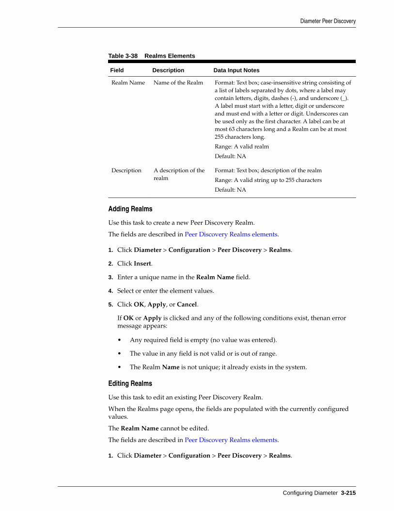
Table 3-38 Realms Elements
Field Description Data Input Notes
Realm Name Name of the Realm Format: Text box; case-insensitive string consisting ofa list of labels separated by dots, where a label maycontain letters, digits, dashes (-), and underscore (_).A label must start with a letter, digit or underscoreand must end with a letter or digit. Underscores canbe used only as the first character. A label can be atmost 63 characters long and a Realm can be at most255 characters long.
Range: A valid realm
Default: NA
Description A description of therealm
Format: Text box; description of the realm
Range: A valid string up to 255 characters
Default: NA
Adding Realms
Use this task to create a new Peer Discovery Realm.
The fields are described in Peer Discovery Realms elements.
1. Click Diameter > Configuration > Peer Discovery > Realms.
2. Click Insert.
3. Enter a unique name in the Realm Name field.
4. Select or enter the element values.
5. Click OK, Apply, or Cancel.
If OK or Apply is clicked and any of the following conditions exist, thenan errormessage appears:
• Any required field is empty (no value was entered).
• The value in any field is not valid or is out of range.
• The Realm Name is not unique; it already exists in the system.
Editing Realms
Use this task to edit an existing Peer Discovery Realm.
When the Realms page opens, the fields are populated with the currently configuredvalues.
The Realm Name cannot be edited.
The fields are described in Peer Discovery Realms elements.
1. Click Diameter > Configuration > Peer Discovery > Realms.
Diameter Peer Discovery
Configuring Diameter 3-215

2. Select the Realm Name to edit.
3. Click Edit.
4. Update the relevant fields.
5. Click OK, Apply, or Cancel.
If OK or Apply is clicked and any of the following conditions exist, then an errormessage appears:
• The selected Realm Name no longer exists; it has been deleted by another user.
• Any field is empty (no value was entered).
• The value in any field is not valid or is out of range.
Deleting Realms
Use this task to delete Peer Discovery Realms.
1. Click Diameter > Configuration > Peer Discovery > Realms.
2. Select the Realm Name you want to delete.
3. Click Delete.
A popup window appears to confirm the delete.
4. Click OK or Cancel.
DNS SetsThe Diameter > Configuration > Peer Discovery > DNS Sets page displays the DNSSets GUI page.
You can perform these tasks on an Active System OAM (SOAM).
On the Diameter > Configuration > Peer Discovery > DNS Sets page, you canperform the following actions:
• Filter the list of DNS Sets to display only the desired DNS Sets.
• Sort the list by a column, in ascending or descending order, by clicking the columnheading. The default order is by DNS Sets Name in ascending ASCII order.
• Click Insert.
On the DNS Sets [Insert] page, you can add a new DNS Sets. See Adding DNSSets.
If the maximum number of DNS Sets already exists in the system, an errormessage displays.
• Select a DNS Sets Name in the list and click Edit to display the DNS Sets[Edit]page and edit the selected Realm. See Editing DNS Sets.
• Select a DNS Sets Name and click Delete to remove the selected DNS Sets Name.See Deleting DNS Sets.
Diameter Peer Discovery
3-216 Diameter Signaling Router Diameter User's Guide

Peer Discovery DNS Sets elements
Table 3-39 describes fields on the DNS Sets View, Insert, Edit pages. Data Input Notesapply only to the Insert and Edit pages; the View page is read-only.
This DNS Sets page shows all DNS Sets configured for potential Dynamic PeerDiscovery.
Note: Although a DNS set is listed on the DNS Sets GUI page, this does notmean it is used for DPD. Configured DNS sets displayed on this page arecandidates for DPD; the DNS sets listed here become available on theDiscovery Attributes page. See Discovery Attributes.
Table 3-39 DNS Sets Elements
Field Description Data Input Notes
DNS SetName
Name of the DNS Set. Format: text box; case sensitive;alphanumeric and underscore
Range: 1 - 32 characters, cannot start witha digit and must contain at least onealpha
Default: NA
Primary DNSServer IPAddress
IP address of the primary DNSserver.
Format: valid IP address
Range: 39 characters (The longest IPv6address that can be formed is 8 octets of 4characters (=32) plus seven colondelimiters (=7), for a total of 39characters.
SecondaryDNS ServerIP Address
IP address of the secondary DNSserver.
Format: valid IP address
Range: 39 characters (The longest IPv6address that can be formed is 8 octets of 4characters (=32) plus seven colondelimiters (=7), for a total of 39characters.
DNS QueryTimeout (sec)
Specifies how long theapplication waits for a responsefrom the DNS server.
Format: numeric value
Range: 1 - 4 seconds
Default: 2
Number ofRetries
Specifies how many times theapplication retires if the DNAquery times out.
Format: numeric value
Range: 1 - 3 seconds
Default: 2
Adding DNS Sets
Use this task to create a new DNS Set.
The fields are described in Peer Discovery DNS Sets elements.
1. Click Diameter > Configuration > Peer Discovery > DNS Sets.
Diameter Peer Discovery
Configuring Diameter 3-217
2. Click Insert.
3. Enter a unique name in the DNS Set Name field.
4. Select or enter the element values.
5. Click:
• OK to save the new DNS Set name and return to the DNS Sets page.
Note: This assumes all validation checks pass.
• Apply to save the new DNS Set name and remain on this page.
Note: This assumes all validation checks pass.
• Cancel to return to the DNS Sets page without saving any changes.
If OK or Apply is clicked and any of the following conditions exist, then an errormessage appears:
• Any validation checks fail.
• Any required field is empty (no value was entered).
• The value in any field is not valid or is out of range.
• The DNS Set Name is not unique; it already exists in the system.
• The maximum number of DNS Sets already exists in the system.
• The secondary IP address duplicates the primary IP address.
• The pair of IP addresses (primary/secondary) duplicates the pair alreadydefined for another DNS Set.
Note: Exchanging the primary and secondary IP addresses does notconstitute a unique DNS set.
Editing DNS Sets
Use this task to edit existing DNS Sets.
When the DNS Sets page opens, the fields are populated with the currently configuredvalues.
The DNS Set Name cannot be edited.
The fields are described in Peer Discovery DNS Sets elements.
1. Click Diameter > Configuration > Peer Discovery > DNS Sets.
2. Select the DNS Set Name to edit.
3. Click Edit.
4. Update the relevant fields.
Diameter Peer Discovery
3-218 Diameter Signaling Router Diameter User's Guide

5. Click OK, Apply, or Cancel.
If OK or Apply is clicked and any of the following conditions exist, then an errormessage appears:
• The selected DNS Set Name no longer exists; it has been deleted by anotheruser.
• The selected DNS Set Name is referenced by one or more administrativelyenabled Discovery Attributes.
Note: You can edit an administratively disabled Discovery Attribute, becausechanging the DNS Set attributes has no impact on active Realm discovery.
• Any validation checks fail.
• Any required field is empty (no value was entered).
• The value in any field is not valid or is out of range.
• The DNS Set Name is not unique; it already exists in the system.
• The maximum number of DNS Sets already exists in the system.
• The secondary IP address duplicates the primary IP address.
• The pair of IP addresses (primary/secondary) duplicates the pair alreadydefined for another DNS Set.
Note: Exchanging the primary and secondary IP addresses does notconstitute a unique DNS set.
Deleting DNS Sets
Use this task to delete DNS Sets.
The default DNS Set Name can be edited, but cannot be deleted.
1. Click Diameter > Configuration > Peer Discovery > DNS Sets.
2. Select the DNS Set you want to delete.
3. Click Delete.
A popup window appears to confirm the delete.
Note: Deletion is only possible if all validation checks pass. If validation fails,an error code displays.
4. Click OK or Cancel.
Discovery AttributesThe Diameter > Configuration > Peer Discovery > Discovery Attributes pagedisplays the Discovery Attributes GUI page.
You can perform these tasks on an Active System OAM (SOAM).
Diameter Peer Discovery
Configuring Diameter 3-219

On the Diameter > Configuration > Peer Discovery > Discovery Attributes page, youcan perform the following actions:
• Filter the list of Discovery Attributes.
Note: You can filter up to four columns simultaneously by using thecompound filter widget.
• Sort by a column, in ascending or descending order, by clicking the columnheading.
• Click Insert.
On the Discovery Attributes > [Insert] page, you can add a new DiscoveryAttribute.
If the maximum number of Discovery Attributes already exists in the system, anerror message displays.
• Select an attribute in the list and click Edit to display the DiscoveryAttributes[Edit] page and edit the selected attribute. See Editing DiscoveryAttributes.
• Select an attribute and click Delete to remove the selected item. See DeletingDiscovery Attributes.
Peer Discovery Attributes element
Table 3-40 describes fields on the Discovery Attributes View, Insert, Edit pages. DataInput Notes apply only to the Insert and Edit pages; the View page is read-only.
This Discovery Attributes page shows all Discovery Attributes configured for peerdiscovery.
Table 3-40 Discovery Attributes Elements
Field Description Data Input Notes
Realm Name Name of the Realm where DiameterPeers are to be discovered.
Format: List
Range: NA
Default: NA
DNS Set DNS server set used for Peer Discovery. Format: List
Default: -Select-
Local Node Local Node used to connect to all Peersdiscovered within the Realm.
Format: List
Range: NA
Default: Initiator & Responder
Diameter Peer Discovery
3-220 Diameter Signaling Router Diameter User's Guide

Table 3-40 (Cont.) Discovery Attributes Elements
Field Description Data Input Notes
ConnectionMode
Specifies the connection mode used forPeer discovery.
Format: List
Range:• Initiator Only indicates that
all connections to discoveredPeers are Initiator Only; theapplication attempts to initiateconnection to these Peers.
• Initiator and Responderindicates that all connectionsto discovered Peers are of thetype Initiator and Responder;the application attempts toinitiate connection to thediscovered Peers as well aslisten for connection attemptsfrom these Peers.
Default: Initiator & Responder
LocalProtocolPreferenceOverride
If checked, this indicates that the localprotocol preferences specified for eachApplication ID take precedence overthe protocol preferences discovered foreach Peer in the Realm.
Format: checkbox
Range: checked, unchecked
Default: Unchecked
Applications List of applications used for peer discovery.
CEX ParametersCEX parameters to be searched. You canspecify up to ten parameters. .If no Vendor IDs are associated with theselected CEX parameter, AdditionalSupported Vendor IDs is empty.
Note: Because each Realm can haveone to ten CEX parameters, you mustuse the plus (+) symbol to expand thelist. Sorting by any of the fieldsassociated with the CEX parameter isnot supported on the view page.
CEX ParametersFormat: ListRange: Configured CEXparametersDefault: -Select-
Additional Supported Vendor IDsVendor IDs, in addition to the onespecified in the CEX parameter list,which can be paired with theApplication ID.
Additional Supported Vendor IDsFormat: Selection listRange: Vendor IDs configured forthe Application IDDefault: NA
Diameter Peer Discovery
Configuring Diameter 3-221

Table 3-40 (Cont.) Discovery Attributes Elements
Field Description Data Input Notes
Protocol PreferencesIf zero, the associated protocol is notused for connections to a discoveredPeer. Values 1 - 4 indicate thehierarchical local protocol preferences(1 is most preferred, 4 is leastpreferred).You can assign the same value to morethan one protocol.
Note: This selection is not required ifthe Local Protocol Preference Overridecheckbox is unchecked on the viewpage.
Protocol PreferencesFormat: Lists for TCP, SCTP, TLS,and DTLS)Range: 0 - 4Default: -Select-
Max Num PeersThe maximum number of peers withinthe Realm that are created for theselection Application ID.
Max Num PeersFormat: numericRange: 1 - 3Default: 2
Max Num ConnectionsThe maximum number of peers withinthe Realm that are created spanningdiscovered Peers that support theassociated Application ID.
Max Num ConnectionsFormat: numericRange: 1 - 64Default: 2
Local IPAddress
Specifies the local IP address to be usedas the Local Node address for alldynamic connections made to Peers inthis Realm.
Note: SCTP multi-homed connectionsto discovered Peers are not supported.
Format: List
Range:
Default:
IPFE InitiatorDAMP
Specifies the DA-MP that initiates thedynamic connections.
Note: This is mandatory if the LocalIP Address is a Target Set address;otherwise it is not applicable.
Format: ListRange:
Default:
Diameter Peer Discovery
3-222 Diameter Signaling Router Diameter User's Guide

Table 3-40 (Cont.) Discovery Attributes Elements
Field Description Data Input Notes
ConnectionConfigurationSet
Specifies the configuration set to beused when dynamic connections aremade to Peers in this Realm.
Format: List
Range: NA
Default: Default
CapacityConfigurationSet
Specifies the capacity configuration setto be used by all dynamic connectionsmade to Peers in this Realm.
Format: List
Range: NA
Default: Default
Realm Prefix Specifies the Realm prefix to be used asthe first portion of the name of allconfiguration objects that aredynamically created by the applicationas a function of Realm discovery.
Format: text box; case sensitive;alphanumeric and underscore
Range: 1 - 12 characters, cannotstart with a digit and must containat least one alpha
Range: NA
Default: Default
Adding Discovery Attributes
Use this task to create new Discovery Attributes.
The fields are described in Peer Discovery Realms elements.
1. Click Diameter > Configuration > Peer Discovery > Discovery Attributes.
2. Click Insert.
3. Specify a unique name in the Realm Name field.
4. Select or enter the element values.
5. Click:
• OK to save the new Discovery Attributes and return to the DiscoveryAttributes page.
Note: This assumes all validation checks pass.
• Apply to save the new Discovery Attributes and remain on this page.
Note: This assumes all validation checks pass.
• Cancel to return to the Discovery Attributes page without saving any changes.
If OK or Apply is clicked and any of the following conditions exist, then an errormessage appears:
• The Connection Mode for a Realm being discovered is Initiator & Responder,and the Local Node assigned to the Discovery Attributes instance does nothave a Listen Port assigned to at least one protocol.
Diameter Peer Discovery
Configuring Diameter 3-223

Note: In order for any dynamically-created Connection to act in the role ofResponder, a Listen Port must be assigned for one or more protocols. If theRealm's Connection Mode is Initiator, then Listen Ports do not have to besupplied.
• The Local Protocol Preference Override value is Yes, and the preference valuefor all protocols associated with any configured Application Id is zero or ismissing.
• Any validation checks fail.
• Any required field is empty (no value was entered).
• The value in any field is not valid or is out of range.
• Any required information is not unique; it already exists in the system.
• The maximum number of any of the discovery attributes already exists in thesystem.
Editing Discovery Attributes
Use this task to edit existing Discovery Attributes.
When the Discovery Attributes page opens, the fields are populated with the currentlyconfigured values.
The Realm Name cannot be edited.
1. Click Diameter > Configuration > Peer Discovery > Discovery Attributes.
2. Select a row to edit.
3. Click Edit.
4. Update the relevant fields.
5. Click OK, Apply, or Cancel.
If OK or Apply is clicked and any of the following conditions exist, then an errormessage appears:
• The selected element no longer exists; it has been deleted by another user.
• The selected element is referenced by one or more administratively enabledDiscovery Attributes.
Note: You can edit an administratively disabled Discovery Attribute, becausechanging the DNS Set attributes has no impact on active Realm discovery.
• Any validation checks fail.
• Any required field is empty (no value was entered).
• The value in any field is not valid or is out of range.
• The Realm Name is not unique; it already exists in the system.
Diameter Peer Discovery
3-224 Diameter Signaling Router Diameter User's Guide

• The Connection Mode for a Realm being discovered is Initiator & Responder,and the Local Node assigned to the Discovery Attributes instance does nothave a Listen Port assigned to at least one protocol.
Note: In order for any dynamically-created Connection to act in the role ofResponder, a Listen Port must be assigned for one or more protocols. If theRealm's Connection Mode is Initiator, then Listen Ports do not have to besupplied.
• The Local Protocol Preference Override value is Yes, and the preference valuefor all protocols associated with any configured Application Id is zero or ismissing.
• The maximum number of a selected element already exists in the system.
Deleting Discovery Attributes
Use this task to delete Discovery Attributes.
1. Click Diameter > Configuration > Peer Discovery > Discovery Attributes.
2. Select the row you want to delete.
3. Click Delete.
A popup window appears to confirm the delete.
Note: Deletion is only possible if all validation checks pass. If validation fails,an error code displays.
4. Click OK or Cancel.
Diameter Peer Discovery
Configuring Diameter 3-225

Diameter Peer Discovery
3-226 Diameter User's Guide

4Diameter Maintenance
The Diameter > Maintenance pages display status information for Route Lists, RouteGroups, Peer Nodes, Connections, Egress Throttle Groups, diameter applications, andDiameter Agent Message Processors (DA-MPs).
On the Diameter > Maintenance > Connections page you can enable and disableConnections.
Diameter Maintenance OverviewThe Diameter > Maintenance pages allow you to view the following information andperform the following actions:
• On the Diameter > Maintenance pages you can view status information for RouteLists, Route Groups, Peer Nodes, Connections, Egress Throttle Groups, diameterapplications, and Diameter Agent Message Processors (DA-MPs).
• On the Diameter > Maintenance > Connections page you can enable and disableConnections.
• On the Diameter > Maintenance > Applications page you can enable and disablediameter applications.
Diameter Maintenance Route ListsThe Diameter > Maintenance > Route Lists page displays the Minimum AvailabilityWeight and Route Group assignments for configured Route Lists. You can also viewthe Priority, Active/Standby assignments, Provisioned Capacity, Current Capacity,and the Status of Route Groups assigned to a Route List.
You can perform these tasks on an Active System OAM (SOAM).
This information can be used to determine if changes need to be made to the PeerRouting Rules Route List assignments to better facilitate Diameter message routing.Additionally, this information is useful for troubleshooting alarms.
On the Diameter > Maintenance > Route Lists page, you can perform the followingactions:
• Filter the list of Route Lists to display only the desired Route Lists.
• Sort the list by a column, in ascending or descending order, by clicking the columnheading. The default order is by Route List Name in ascending ASCII order.
• Prevent the page from automatically refreshing by clicking the Pause updatescheck box.
Diameter Maintenance 4-1

Diameter Route List maintenance elementsTable 4-1 describes fields on the Route Lists maintenance page.
Table 4-1 Route Lists Maintenance Elements
Field Description
Route List Name Name of the Route List.
Minimum RouteGroup AvailabilityWeight
Minimum Route Group availability weight for this Route List.
Route Group Route Groups assigned to the Route List.
MP Server Hostname Hostname of the Message Processor Server from which status isreported.• For a Multiple Active DA-MP configuration, the MP Leader
always reports the Route List status• For an Active/Standby DA-MP configuration, the Active DA-
MP reports the Route List status
Dynamic Indicates whether or not the element was created dynamically (YES)or statically (NO). NO is assigned for all element instances, exceptfor those created via Dynamic Peer Discovery.
Priority Priority of each Route Group in the Route List.
Provisioned Capacity Capacity assignment for each Route Group in the Route List.
Current Capacity Current capacity available for each Route Group in the Route List.
Active/Standby A Route Group can be:• Active: this is the Route Group that Diameter messages are
actively being routed to• Standby: messages are not currently being routed to this Route
Group, unless the Active Route Group is unavailable and RouteAcross Route Groups is enabled on the Route List
• Unk: information on this Route Group is not present in thedatabase
Status Route List or Route Group status can be:• Available: the available capacity of the Route Group is greater
than the Minimum Route Group Availability Weight• Degraded: the available capacity of the Route Group is greater
than zero, but less than the Minimum Route Group AvailabilityWeight
• Unavailable: the Route Group available capacity is zero• Unk: status information is not available in the database
Time of Last Update Time stamp that shows the last time the status information wasupdated.
Diameter Maintenance Route Lists
4-2 Diameter Signaling Router Diameter User's Guide

Diameter Maintenance Route GroupsThe Diameter > Maintenance > Route Groups page allows you to view theProvisioned Capacity and Available Capacity for Route Groups and to viewinformation about Peer Nodes or Connections assigned to a Route Group.
You can perform these tasks on an Active System OAM (SOAM).
This information can be used to determine if changes need to be made to the PeerNode or Connection assignments in a Route Group in order to better facilitateDiameter message routing. Additionally, this information is useful for troubleshootingalarms.
On the Diameter > Maintenance > Route Groups page, you can perform thefollowing actions:
• Filter the list of Route Groups to display only the desired Route Groups.
• Sort the list by Route Group Name, in ascending or descending order, by clickingthe column heading. The default order is ascending ASCII order.
• Click the + in any entry in the Peer Node/Connection field to view informationabout the Peer Nodes or Connections in a Route Group.
• With an entry in the Peer Node/Connection field expanded, click the Peer Nodeor Connection Name to go to the maintenance page for the Peer Node orConnection.
• Prevent the page from automatically refreshing by clicking the Pause updatescheck box.
Diameter Route Group maintenance elementsTable 4-2 describes fields on the Diameter > Maintenance Route Groups page.
Table 4-2 Route Group Maintenance Elements
Field Description
Route GroupName
Name of the route group.
Peer Node/Connection
Number and names of peer nodes or connections in the route group.
MP ServerHostname
Hostname of MP server from which status is reported.• For a multiple active DA-MP configuration, the MP leader always
reports the route group statu• For an active/standby DA-MP configuration, the active DA-MP
reports the route group statu
Dynamic Indicates whether or not the element was created dynamically (YES) orstatically (NO). NO is assigned for all element instances, except for thosecreated via dynamic peer discovery.
Diameter Maintenance Route Groups
Diameter Maintenance 4-3

Table 4-2 (Cont.) Route Group Maintenance Elements
Field Description
ProvisionedCapacity
• For a peer route group, the sum total of the provisioned capacity ofall the peer nodes in the route group.
• For a connection route group, the sum total of the provisionedcapacity of all the connections in the route group.
ProvisionedPercent
The percentage of capacity assigned to each peer node/connectioncompared to all peer nodes/connections in the route group.
AvailableCapacity
• For a peer route group, the sum total of the available capacity of allthe peer nodes in the route group.
• For a connection route group, the sum total of available capacity ofall the connections in the route group.
Available Percent The percentage of capacity the peer node/connection currently hascompared to the total available capacity of all peer nodes/connections inthe route group.
Peer Node/ConnectionStatus
Peer node/connection status can be:• Available: the available capacity is greater than the minimum
capacity• Degraded: the available capacity is greater than zero, but less than
the provisioned capacity• Unavailable: the available capacity is zero• Unk: status information is not available in the database
TrafficMeasurement
Traffic measurement can be enabled or disabled for a peer route group.Up to 250 route groups can be enabled (including peer and connectionroute groups). When enabled, this field measures how many request andanswer messages are successfully forwarded and received to and fromroute groups.
Time of LastUpdate
Time stamp that shows the last time the status information was updated.
Diameter Maintenance Peer NodesThe Diameter > Maintenance > Peer Nodes page provides the operational status ofPeer Node connections, including a reason for the status.
You can perform these tasks on an Active System OAM (SOAM).
On the Diameter > Maintenance > Peer Nodes page, you can perform the followingactions:
• Filter the list of Peer Nodes to display only the desired Peer Nodes.
• Sort the list by a column, in ascending or descending order, by clicking the columnheading (except MP Server Hostname and Connection). The default order is byPeer Node Name in ascending ASCII order.
• Click the + in any entry in the Connection field to view information about theConnections associated with the Peer Node.
Diameter Maintenance Peer Nodes
4-4 Diameter Signaling Router Diameter User's Guide

• With an entry in the Connection field expanded, click the Connection Name to goto the maintenance page for the Connection.
• Prevent the page from automatically refreshing by clicking the Pause updatescheck box.
Diameter Peer Node maintenance elementsTable 4-3 describes fields on the Peer Nodes maintenance page.
Table 4-3 Peer Nodes Maintenance Elements
Field Description
Peer Node Name Name of the Peer Node.
MP ServerHostname
Hostname of MP server from which status is reported.
For the Peer Node status:• For a Multiple Active DA-MP configuration, the MP Leader always
reports the Peer Node status• For an Active/Standby DA-MP configuration, the Active DA-MP
reports the Peer Node status
For Connection status (when the Connection field is expanded):• Fixed (non-IPFE) Connections are always reported by the DA-MP
that hosts the Fixed Connection• Owned IPFE Connections are always reported by the DA-MP that
hosts the established IPFE Connection• Unowned IPFE Connections (ones that have been configured, but
are currently not assigned to a DA-MP by IPFE) are reported by theMP Leader
Dynamic Indicates whether or not the element was created dynamically (YES) orstatically (NO). NO is assigned for all element instances, except forthose created via Dynamic Peer Discovery.
Operational Status Peer Node Operational Status can be:• Available: at least one Peer Node connection is available for routing• Degraded: the Peer Node connection is not unavailable but it is not
operating as expected. The Operational Reason field providesadditional information on this status.
• Unavailable: all connections for a Peer Node are unavailable. TheOperational Reason field provides additional information on thisstatus.
OperationalReason
Reason for the Peer Node Operational Status. Information is alsoavailable for each connection.
Connection Number and names of connections associated with the Peer Node.
Time of LastUpdate
Time stamp that shows the last time the status information wasupdated.
Peer Node GroupName
A group of Peer Nodes that share common characteristics andattributes. This group is used by IPFE for Peer Node Group Awareconnection distribution.
Diameter Maintenance Peer Nodes
Diameter Maintenance 4-5

Table 4-3 (Cont.) Peer Nodes Maintenance Elements
Field Description
TransactionConfiguration SetName
Unique name of the Transaction Configuration Set.
Diameter Maintenance ConnectionsThe Diameter > Maintenance > Connections page allows you to view informationabout existing connections, including the operational status of each connection.
You can perform these tasks on an Active System OAM (SOAM).
On the Diameter > Maintenance > Connections page, you can perform the followingactions:
• Filter the list of Connections to display only the desired Connections.
• Sort the list by a column, in ascending or descending order, by clicking the columnheading. The default order is by Connection Name in ascending ASCII order.
• Click a Local Node to go the configuration page for the Local Node.
• Click a Peer Node to go to the maintenance page or the Peer Node.
• Click a Message Priority or Egress Message Throttling Configuration Set to go tothe configuration page for the Configuration Set.
• Prevent the page from automatically refreshing by clicking the Pause updatescheck box.
• Enable connections.
• Disable connections.
• View statistics for an SCTP connection.
• Run diagnostics on a test connection.
For information about diagnostics reports, see Viewing, Printing, and SavingDiagnostics Tool Reports.
Diameter Connection maintenance elementsTable 4-4 describes fields on the Connections maintenance page.
Table 4-4 Connections Maintenance Elements
Field Description
Connection Name Name of the Connection
Diameter Maintenance Connections
4-6 Diameter Signaling Router Diameter User's Guide

Table 4-4 (Cont.) Connections Maintenance Elements
Field Description
MP ServerHostname
Hostname of the MP server from which status is reported:• Fixed (non-IPFE) Connections are always reported by the DA-MP
that hosts the Fixed Connection• Established IPFE Connections are always reported by the DA-MP
that hosts the established IPFE Connection• Non-Established IPFE Connections (ones that have been
configured, but are currently not assigned to a DA-MP by IPFE)are reported by the MP Leader
Dynamic Indicates whether or not the element was created dynamically (YES)or statically (NO). NO is assigned for all element instances, except forthose created via Dynamic Peer Discovery.
Admin State A Connection's administrative state can be:• Enabled: the Connection is Enabled• Disabled: the Connection is Disabled• Unk: unknown; the state of the Connection is not available in the
database
Connection Type Indicates the connection type (Diameter or (RADIUS).
Connection Mode Specifies the connection mode used for Peer discovery.
The Connection can have one of the following Connection Modes:
Initiator OnlyIndicates that all connections to discovered Peers are Initiator Only; theapplication attempts to initiate connection to these Peers.
Initiator & ResponderIndicates that all connections to discovered Peers are of the typeInitiator & Responder; the application attempts to initiate connectionto the discovered Peers as well as listen for connection attempts fromthese Peers.
RADIUS ServerIndicates that RCL can only receive RADIUS Request messages andsend RADIUS Response messages of the Connection.
RADIUS ClientIndicates that RCL can only send RADIUS Request messages andreceives RADIUS Response messages of the Connection.
Operational Status A Connection's administrative state can be:• Available: the Connection is available for routing• Degraded: the Connection is not unavailable but it is not
operating as expected. The Operational Reason field providesadditional information on this status.
• Unavailable: the Connection is unavailable. The OperationalReason field provides additional information on this status.
Diameter Maintenance Connections
Diameter Maintenance 4-7

Table 4-4 (Cont.) Connections Maintenance Elements
Field Description
CPL The Connection Priority Level is the maximum of the followingvalues:• Operational Status (0=available; 3=degraded; 99=unavailable)• Remote Busy Congestion Level (0-3)• Egress Transport Congestion Level (0-98)• Egress Message Rate Congestion Level (0-3)
Operational Reason Reason for the Operational Status. The following reasons can occur:• Disabled• Connecting• Listening• Abnormal• Disconnecting• Proving• Watchdog• Remote Busy Congestion• Egress Transport Congestion• Egress Message Rate Congestion• Normal• Peer with reduced IP set
Local Node Local Node associated with the Connection
Local Port Specifies the local port used for Peer discovery.
IPFE Initiator DAMP The IPFE Initiator DA-MP for this connection.
Peer Node Peer Node associated with the Connection
Remote IPAddresses
The IP address(es) of the Peer Node associated with the Connection
Remote Port The Listen Port of the Peer Node associated with the Connection
Local Initiate Port The Local Initiate Port associated with the Connection
Ingress Msgs PerSecond
A 30-second running average of the Ingress messages processed by theConnection
CommonApplication IDs
A comma-separated list of Application IDs received in a DiameterCEA message, or a list of Application Names. The first 10 ApplicationIDs received in the CEA are listed.
Note: For local nodes, CEAs are sent in response to erroneous CERs.
TransportCongestionAbatement Timeout
The amount of time spent at Egress Transport Congestion Levels 3, 2,and 1 during Egress Transport Congestion Abatement
Diameter Maintenance Connections
4-8 Diameter Signaling Router Diameter User's Guide

Table 4-4 (Cont.) Connections Maintenance Elements
Field Description
Remote Busy Usage Indicates which Request messages can be forwarded on thisConnection after receiving a DIAMETER_TOO_BUSY response fromthe Connection's Peer.
DisabledThe Connection is not considered to be BUSY after receiving aDIAMETER_TOO_BUSY response. All Request messages continue tobe forwarded to (or rerouted to) this Connection.
EnabledThe Connection is considered to be BUSY after receiving aDIAMETER_TOO_BUSY response. No Request messages areforwarded to (or rerouted to) this Connection until the Remote BusyAbatement Timeout expires.
Host OverrideThe Connection is considered to be BUSY after receiving aDIAMETER_TOO_BUSY response. Only Request messages whoseDestination-Host AVP value is the same as the Connection's PeerFQDN can be forwarded to (or rerouted to) this Connection until theRemote Busy Abatement Timeout expires.
Remote BusyAbatement Timeout
If Remote Busy Usage is Enabled or Host Override, this is the time inseconds that the Connection is considered BUSY from the last time aDIAMETER_TOO_BUSY response was received.
Message PrioritySetting
Indicates the source of Message Priority for a Request messagearriving on the Connection. Possible settings are:• None - use the Default Message Priority Configuration Set• Read from Request Message - read the Message Priority from the
ingress Request• User Configured - Apply the user configured Message Priority
Configuration Set
Message PriorityConfiguration Set
The Message Priority Configuration Set associated with theConnection
Egress MessageThrottlingConfiguration Set
The Egress Message Throttling Configuration Set associated with theConnection
Egress Msgs PerSecond
The most recent Egress Message Rate on the Connection
Test Mode Indicates if this is a Test Connection
PDUs to Diagnose For a test Connection currently undergoing diagnosis, this shows thenumber of PDUs yet to be diagnosed.
Time of Last Update Time stamp that shows the last time the status information wasupdated
Diameter Maintenance Connections
Diameter Maintenance 4-9

Enabling Connections
Use the following steps to enable one or more connections.
1. Click Diameter > Maintenance > Connections.
2. Select 1 - 20 connections to enable.
To select multiple connections, press CTRL when selecting each connection. Toselect multiple contiguous connections, click the first connection you want, thenpress SHIFT and select the last connection you want. All the connections betweenare also selected.
3. Click Enable.
4. Click OK on the confirmation screen to enable the selected connections.
If any of the selected connections no longer exist (they have been deleted byanother user), an error message displays, but any selected connections that do existare enabled.
Enabling All Connections
Use the following steps to enable all connections that are displayed as result of theapplication of a filter. If a filter is applied, then all connections that meet the filterrequirements and that are currently disabled are enabled. If no filter is applied, then allcurrently disabled connections are enabled.
1. Click Diameter > Maintenance > Connections.
2. Optionally, click Filter and add up to four filters to limit the number of connectionsdisplayed. Click Go to apply the filter.
3. Click Enable All.
4. Click OK on the confirmation screen to enable the connections.
If any of the selected connections no longer exist (they have been deleted byanother user), an error message is displayed, but any selected connections that doexist are enabled.
Disabling Connections
Use the following steps to disable one or more connections.
1. Click Diameter > Maintenance > Connections.
2. Select 1 - 20 connections to disable.
To select multiple connections, press the CTRL key when selecting each connection.To select multiple contiguous connections, click the first connection you want, thenpress the SHIFT key and select the last connection you want. All the connectionsbetween are also selected.
3. Click Disable.
4. Click OK on the confirmation screen to disable the selected connections.
Diameter Maintenance Connections
4-10 Diameter Signaling Router Diameter User's Guide

If any of the selected connections no longer exist (they have been deleted byanother user), an error message is displayed, but any selected connections that doexist are disabled.
Disabling All Connections
Use the following steps to disable all connections that are displayed as result of theapplication of a filter. If a filter is applied, then all connections that meet the filterrequirements and that are currently enabled are disabled. If no filter is applied, then allcurrently enabled connections are disabled.
1. Click Diameter > Maintenance > Connections.
2. Optionally, click Filter and add up to four filters to limit the number of connectionsdisplayed. Click Go to apply the filter.
3. Click Disable All.
4. Click OK on the confirmation screen to disable the connections.
If any of the selected connections no longer exist (they have been deleted byanother user), an error message is displayed, but any selected connections that doexist are disabled.
Connections SCTP StatisticsThe Diameter > Maintenance > Connections > SCTP Statistics page allows you toview statistics about paths within an SCTP connection.
Each line on the Diameter > Maintenance > Connections > SCTP Statistics pagerepresents a path within an SCTP connection.
On the Diameter > Maintenance > Connections > SCTP Statistics page, you can dothe following actions:
• Filter the list of paths to display only the desired paths.
• Get information about the SCTP connection by clicking Info.
• Sort the list by IP Address, in ascending or descending order, by clicking thecolumn heading. The default order is ascending ASCII order.
• Refresh the statistics by clicking Update.
Diameter Connections SCTP Statistics elements
Table 4-5 describes fields on the Diameter > Maintenance > Connections > SCTPStatistics page.
Table 4-5 Connections SCTP Statistics Elements
Field Description
Duplicate TSNs Received A duplicate TSNs received counter on a per SCTP connectionbasis.
Gap AcknowledgementBlock Received
An acknowledgment blocks received counter on a per SCTPconnection basis.
Diameter Maintenance Connections
Diameter Maintenance 4-11

Table 4-5 (Cont.) Connections SCTP Statistics Elements
Field Description
Retransmit Data ChunksSent
A retransmit data chunks sent counter on a per SCTPconnection basis.
Total Data Chunks Sent A total data chunks sent counter on a per SCTP connectionbasis.
IP Address The Peer Remote IP Address associated with the path
State Indicates whether the path is active or inactive
Congestion Window (cwnd) The maximum amount of data, in bytes, that can be sent beforean acknowledgment must be received
Smoothened Round TripTime (srtt) (ms)
The round-trip time, in milliseconds, associated with the path,adjusted to remove sample-to-sample fluctuations
Retr. Timeout (rto) (ms) Retransmission timeout; the amount of time, in milliseconds, towait for an acknowledgment before declaring a transmissionerror
Path MTU (pmtu) Maximum transmission unit; the maximum data unit size, inbytes, that can be sent on the path without fragmentation
Starting Diagnosis on a Test Connection
Use the following steps to start diagnosis on a test connection.
Note: This task is used primarily in lab environments to validate mediationrules, such as checking and debugging ART, PRT, and mediation flows forrequest messages.
In practice, a test request message is put on a test connection, and the user observesDSR processing in response to this message. The resulting report can be viewed on theGUI for analysis. The following rules apply to this task:
• Reroute is not supported
• Error Answers are not generated
• If an Answer is received, it is discarded; it is not routed to the originator
1. Click Diameter > Maintenance > Connections.
2. Select a single connection with the following conditions:
• Admin State is Enabled
• Test Mode is YES.
• PDUs to Diagnose is 0
3. Click Diagnose Start.
Diameter Maintenance Connections
4-12 Diameter Signaling Router Diameter User's Guide

4. Click OK on the confirmation screen to begin the diagnosis on the selected testconnection.
The PDUs to Diagnose value is set to the maximum diagnose PDU count.
If the selected connection no longer exists (it was deleted by another user), an errormessage is displayed and the Diameter > Maintenance > Connections page isrefreshed.
Ending Diagnosis on a Test Connection
Use the following steps to end diagnosis on a test connection.
1. Click Diameter > Maintenance > Connections.
2. Select a single connection with the following conditions:
• Admin State is Enabled
• Test Mode is YES.
• PDUs to Diagnose is greater than 0.
3. Click Diagnose End.
4. Click OK on the confirmation screen to stop the diagnosis on the selected testconnection.
The PDUs to Diagnose value is set to 0.
If the selected connection no longer exists (it was deleted by another user), an errormessage is displayed and the Diameter > Maintenance > Connections page isrefreshed.
Diameter Maintenance Egress Throttle GroupsEgress Throttle Groups are used to perform 2 functions: Rate Limiting and PendingTransaction Limiting. Each of the functions is independent of the other and can beoptionally configured and controlled separately.
You can perform these tasks on an Active System OAM (SOAM).
Due to Egress Throttle Lists functionality, there is an additional maintenanceparameter for Egress Throttle Groups, Control Scope. If the Egress Throttle Groupdoes not belong to an Egress Throttle List, its Control Scope is ETG, which means thategress throttling is controlled by the ETG's configuration data. If the Egress ThrottleGroup is associated with an Egress Throttle List, its Control Scope can either be ETL,which means that egress throttling is controlled by the configuration data for the ETLthat contains the ETG, or ETG, where egress throttling is controlled by theconfiguration data for the ETG. Under normal conditions the expected control scopefor an ETG contained in an ETL would be ETL. A control scope of ETG for an ETGcontained by an ETL can be used for maintenance transitions, such as when the ETG isbeing added or removed from the ETL.
Each function has an individual Control Scope State, as shown in Table 4-6.
Diameter Maintenance Egress Throttle Groups
Diameter Maintenance 4-13

Table 4-6 Egress Throttle Groups Control Scope States
Admin State Description
ETL Egress throttling for Rate Limiting and Pending Transaction Limiting isbeing controlled by the ETL's configuration data.
ETG Egress throttling for Rate Limiting and Pending Transaction Limiting isbeing controlled by the ETG's configuration data.
Each function has an individual Administration State (Enable/Disable) andOperational Status, as shown in Table 4-7.
Table 4-7 Egress Throttle Groups Admin States
Admin State Description
Enable ETG status monitoring is enabled for the function.
Disable ETG status monitoring is disabled for the function. All monitoring isstopped in this state and alarms are cleared.
The Egress Throttle Group maintenance status is displayed on the Diameter >Maintenance > Egress Throttle Groups GUI page. Egress Throttle Groups use theLeader sourcing method for reporting of maintenance status. The Leader sourcingmethod is used because each DA-MP has identical status data; only the DA-MPLeader reports the maintenance status to the GUI. Table 4-8 shows the ETGoperational status.
Table 4-8 ETG Operational Status
ETG OperationalStatus Description
Available ETG monitoring is active and Request throttling is not occurring for thisETG.
Degraded ETG monitoring is active and Request throttling is occurring for this ETG.
Some Requests may be getting throttled based on their Priority
Inactive ETG monitoring is inactive and Request Throttling is not occurring for thisETG. The Operational Reason indicates why this ETG is Inactive.
When Operational Reason is Disabled the ETG is Inactive due tomaintenance actions.
When the Operational Reason is SMS Service Degraded or No DA-MPLeader the ETG is Inactive due to a fault condition.
If either Rate Limiting or Pending Transaction Limiting Operational Status isDegraded, then the Diameter Routing Function throttles the Request messagesaccording to highest severity. For example, if Rate Limiting Operational Status isCongestion Level 1 and Pending Transaction Limiting Operational Status isCongestion Level 2, then the Diameter Routing Function throttles Request messagesaccording to Congestion Level 2 (all Request messages with Priority 0 or 1 arethrottled). As shown in Table 4-9.
Diameter Maintenance Egress Throttle Groups
4-14 Diameter Signaling Router Diameter User's Guide

Table 4-9 ETG Operational Reason
ETG OperationalReason
Description
Disabled ETG is Disabled due to maintenance actions.
Normal No Requests are getting throttled for this ETG for the function.
CongestionLevel 1
Request throttling is happening for Requests with Priority 0.
CongestionLevel 2
Request throttling is happening for Requests with Priority 0 and 1.
CongestionLevel 3
Request throttling is happening for Requests with Priority 0, 1, and 1.
SMS ServiceDegraded
ETG monitoring is Inactive due to "Degraded" status reported to theDiameter Routing Function.
No DA-MPLeader
ETG Monitoring is Inactive due to HA reporting No DA-MP Leadercondition to the Diameter Routing Function.
The Diameter > Maintenance > Egress Throttle Groups page provides theOperational Status of the Egress Throttle Groups Rate Limiting and PendingTransactions Limiting functions, including an Operational Reason for the status.
Egress Throttle Groups maintenance fields are described in Egress Throttle Groupselements
If the column data is not present in the database, the columns for the Egress ThrottleGroup Name are displayed as Unk.
On the Diameter > Maintenance > Egress Throttle Groups page, you can perform thefollowing actions:
• Filter the list of Egress Throttle Groups to display only the Egress Throttle Groups.
• Sort the list by a column, in ascending or descending order, by clicking the columnheading. The default order is by Egress Throttle Groups in ascending ASCIIorder.
• Select one or more (up to 20) Egress Throttle Groups records at a time.
• Enable Rate Limiting for up to 20 selected Egress Throttle Groups.
• Disable Rate Limiting for up to 20 selected Egress Throttle Groups.
• Enable Pending Transaction Limiting for up to 20 selected Egress ThrottleGroups.
• Disable Pending Transactions Limiting for up to 20 selected Egress ThrottleGroups.
• Prevent the page from automatically refreshing every 10 seconds by clicking thePause updates check box.
Diameter Egress Throttle Groups maintenance elementsTable 4-10 describes fields on the Egress Throttle Groups maintenance page.
Diameter Maintenance Egress Throttle Groups
Diameter Maintenance 4-15

Table 4-10 Egress Throttle Groups Maintenance Elements
Field Description
Egress Throttle GroupName
Name of the Egress Throttle Group.
Egress Throttle List Name Name of optional Egress Throttle List that includes this EgressThrottle Group.
Egress Throttle ControlScope
Type of Egress Throttle Control Scope, either ETL for NOAMmanaged egress throttling or ETG for SOAM managed egressthrottling
Rate Limiting Admin State Rate Limiting Admin State can be Enabled or Disabled.
Rate Limiting OperationalStatus
Rate Limiting Operational Status can be:• Available: at least one Egress Throttle Groups peer or
connection is available.• Degraded: the Egress Throttle Groups peer or connection is
not unavailable but it is not operating as expected. TheRate Limiting Operational Reason field provides additionalinformation on this status.
• Inactive: all connections for an Egress Throttle Group areunavailable. The Rate Limiting Operational Reason fieldprovides additional information on this status.
• Unk: data is not available in the database.
Rate Limiting OperationalReason
Rate Limiting Operational Reason as corresponding to the RateLimiting Operational Status:• Available - Normal• Degraded - Congestion Level 1, Congestion Level 2,
Congestion Level 3• Inactive - SMS Service Degraded, No DA-MP Leader,
Disabled• Unk - UnkThe cell background color associated with value of PendingTransaction Limiting Operational Reason is as follows:
• Disabled - normal/no special coloring• Normal - normal/no special coloring• SMS Service Degraded - red• No DA-MP Leader - red• Unk - red• Congestion Level 1 - yellow• Congestion Level 2 - yellow• Congestion Level 3 - yellow
ETG Egress Request Rate The egress request rate to the Peers and Connections that aremembers of the Egress Throttle Group.
ETL Egress Request Rate The egress request rate to the Peers and Connections that aremembers of the ETL's component ETGs.
Pending TransactionLimiting Admin State
Pending Transaction Limiting Admin State can be Enabled orDisabled.
Diameter Maintenance Egress Throttle Groups
4-16 Diameter Signaling Router Diameter User's Guide

Table 4-10 (Cont.) Egress Throttle Groups Maintenance Elements
Field Description
Pending TransactionLimiting OperationalStatus
Pending Transaction Limiting Operational Status can be:• Available: at least one Egress Throttle Groups peer or
connection is available.• Degraded: the Egress Throttle Groups peer or connection is
not unavailable but it is not operating as expected. ThePending Transaction Limiting Operational Reason fieldprovides additional information on this status.
• Inactive: all connections for an Egress Throttle Group areunavailable. The Pending Transaction LimitingOperational Reason field provides additional informationon this status.
• Unk: data is not available in the database.
Pending TransactionLimiting OperationalReason
Pending Transaction Limiting Reason as corresponding to thePending Transaction Limiting Operational Status:• Available - Normal• Degraded - Congestion Level 1, Congestion Level 2,
Congestion Level 3• Inactive - SMS Service Degraded, No DA-MP Leader,
Disabled• Unk - UnkThe cell background color associated with value of PendingTransaction Limiting Operational Reason is as follows:
• Disabled - normal/no special coloring• Normal - normal/no special coloring• SMS Service Degraded - red• No DA-MP Leader - red• Unk - red• Congestion Level 1 - yellow• Congestion Level 2 - yellow• Congestion Level 3 - yellow
Number of ETG PendingTransactions
The combined number of ETG Pending Transactions for thePeers and Connections of an ETG.
Number of ETL PendingTransactions
The combined number of Pending Transactions for the Peersand Connections of the ETL's ETGs.
Number of Active SMSConnections/Number ofRequired SDS Connections
The number of active SMS connections between the signalingrouters with ETGs in the ETL/The number of required SMSconnections between diameter signaling routers with ETGs inthe ETL.
Time of Last Update Displayed as yyyy-month name-date hr:min:sec UTC.
Enabling Egress Throttle Groups Rate Limiting
Use the following procedure to Enable Egress Throttle Groups Rate Limiting.
Diameter Maintenance Egress Throttle Groups
Diameter Maintenance 4-17

The Egress Throttle Groups Rate Limiting Admin State of Egress Throttle Groups canbe updated irrespective of the Operational Status of the associated Peer NodeConnections.
1. Click Diameter > Maintenance > Egress Throttle Groups.
2. Select at least 1, but no more than 20 Egress Throttle Groups to Disable.
To select multiple Egress Throttle Groups, press and hold the CTRL key whenselecting each Egress Throttle Group. To select multiple contiguous Egress ThrottleGroups, click the first Egress Throttle Group to be selected, then press the SHIFTkey and select the last Egress Throttle Group to be selected. All Egress ThrottleGroups between are also selected.
3. Click Enable Rate Limiting.
a. A confirmation box appears if between 1 and 20 Egress Throttle Group Namesare selected.
Click OK in the confirmation box to Enable the selected Egress Throttle GroupNames.
Click Cancel in the confirmation box to cancel the Enable action. The AdminState of the selected Egress Throttle Groups remains unchanged.
If OK is clicked and any of the following conditions exist, then an error messageappears:
• Any of the selected Egress Throttle Groups do not exist in the database.
• Any of the selected Egress Throttle Groups do not have Egress ThrottleGroups Rate Limiting configured.
b. An Alert Box is displayed if more than 20 Egress Throttle Group Names areselected.
Disabling Egress Throttle Groups Rate Limiting
Use the following steps to Disable Egress Throttle Groups Rate Limiting.
The Egress Throttle Groups Rate Limiting Admin State of Egress Throttle Groups canbe updated irrespective of the Operational Status of the associated Peer NodeConnections.
1. Click Diameter > Maintenance > Egress Throttle Groups.
2. Select at least 1, but no more than 20 Egress Throttle Groups to Disable.
To select multiple Egress Throttle Groups, press and hold the CTRL key whenselecting each Egress Throttle Group. To select multiple contiguous Egress ThrottleGroups, click the first Egress Throttle Group to be selected, then press the SHIFTkey and select the last Egress Throttle Group to be selected. All Egress ThrottleGroups between are also selected.
3. Click Disable Rate Limiting.
a. A confirmation box appears if between 1 and 20 Egress Throttle Groups areselected.
Diameter Maintenance Egress Throttle Groups
4-18 Diameter Signaling Router Diameter User's Guide

Click OK in the confirmation box to Disable the selected Egress ThrottleGroups.
Click Cancel in the confirmation box to cancel the Disable action. The AdminState of the selected Egress Throttle Groups remains unchanged.
If OK is clicked and any of the following conditions exist, then an error messageappears:
• Any of the selected Egress Throttle Groups do not exist in the database.
• Any of the selected Egress Throttle Groups do not have the EgressThrottling Groups Rate Limiting configured.
b. An Alert Box is displayed if more than 20 Egress Throttle Groups are selected.
Enabling Egress Throttle Groups Pending Transaction Limiting
Use the following steps to Enable Egress Throttle Groups Pending TransactionLimiting.
The Egress Throttle Groups Pending Transaction Limiting Admin State of EgressThrottle Groups can be updated irrespective of the Operational Status of the associatedPeer Node Connections.
1. Click Diameter > Maintenance > Egress Throttle Groups.
2. Select at least 1, but no more than 20 Egress Throttle Groups to Disable.
To select multiple Egress Throttle Groups, press and hold the CTRL key whenselecting each Egress Throttle Group. To select multiple contiguous Egress ThrottleGroups, click the first Egress Throttle Group to be selected, then press the SHIFTkey and select the last Egress Throttle Group to be selected. All Egress ThrottleGroups between are also selected.
3. Click Enable Pending Transaction Limiting.
a. A confirmation box appears if between 1 and 20 Egress Throttle Group Namesare selected.
Click OK in the confirmation box to Enable the selected Egress Throttle GroupNames.
Click Cancel in the confirmation box to cancel the Enable action. The AdminState of the selected Egress Throttle Groups remains unchanged.
If OK is clicked and any of the following conditions exist, then an error messageappears:
• Any of the selected Egress Throttle Groups do not exist in the database.
• Any of the selected Egress Throttle Groups do not have Egress ThrottlingGroups Pending Transaction Limiting configured.
b. An Alert Box is displayed if more than 20 Egress Throttle Groups are selected.
Diameter Maintenance Egress Throttle Groups
Diameter Maintenance 4-19

Disabling Egress Throttle Groups Pending Transaction Limiting
Use the following steps to Disable Egress Throttle Groups Pending TransactionLimiting.
The Egress Throttle Groups Pending Transaction Limiting Admin State of EgressThrottle Groups can be updated irrespective of the Operational Status of the associatedPeer Node Connections.
1. Click Diameter > Maintenance > Egress Throttle Groups.
2. Select at least 1, but no more than 20 Egress Throttle Groups to Disable.
To select multiple Egress Throttle Groups, press and hold the CTRL key whenselecting each Egress Throttle Group. To select multiple contiguous Egress ThrottleGroups, click the first Egress Throttle Group to be selected, then press the SHIFTkey and select the last Egress Throttle Group to be selected. All Egress ThrottleGroups between are also selected.
3. Click Disable Pending Transaction Limiting.
a. A confirmation box appears if between 1 and 20 Egress Throttle Groups areselected.
Click OK in the confirmation box to Disable the selected Egress ThrottleGroups.
Click Cancel in the confirmation box to cancel the Disable action. The AdminState of the selected Egress Throttle Groups remains unchanged.
If OK is clicked and any of the following conditions exist, then an error messageappears:
• Any of the selected Egress Throttle Groups do not exist in the database.
• Any of the selected Egress Throttle Groups do not have the EgressThrottling Pending Transaction Limiting configured.
b. An Alert Box is displayed if more than 20 Egress Throttle Groups are selected.
Diameter Maintenance ApplicationsThe Diameter > Maintenance > Applications page allows you to view state andcongestion information about existing diameter applications and can enable anddisable diameter applications.
You can perform these tasks on an Active System OAM (SOAM).
If the MAP-Diameter InterWorking Function (IWF) is activated, you can view andconfigure items in the Map Internetworking folder. After activation, all selectableMAP-Diameter IWF related menu items are present on the SOAM and NOAM GUI,which allows full MAP-Diameter IWF configuration and provisioning. By default,MAP Interworking is not activated.
On the Diameter > Maintenance > Applications page, you can perform the followingactions:
Diameter Maintenance Applications
4-20 Diameter Signaling Router Diameter User's Guide

• Filter the list of Applications to display only the desired Applications.
• Sort the list by column, in ascending or descending order, by clicking the columnheading. The default order is by Application Name in ascending ASCII order.
• Change the Admin State of a selected application to Enabled or Disabled on aselected MP server. See Enabling Applications and Disabling Applications.
• Prevent the page from automatically refreshing by clicking the Pause updatescheck box.
• Enable and disable the DM-IWF and MD-IWF applications.
See MAP-Diameter Interworking Function User's Guide for additional information.
Diameter Applications maintenance elementsTable 4-11 describes fields on the Applications maintenance page.
Table 4-11 Applications Maintenance Elements
Field Description
Application Name Name of the application
MP ServerHostname
Hostname of the Message Processorserver from which status isreported
Admin State Admin State of the application (Enabled, Disabled). The Admin Statepersists over application restart and server reboot.
Operational Status Operational Status of the application (Unavailable, Available, orDegraded)
Operational Reason Operational Reason that is filled in by the application and extractedfrom the database
Congestion Level Congestion Level of the application (Normal, CL1, CL2, CL3)
Time of Last Update Time stamp that shows when the application changed to the statusshown in Operational State
If the run-time data for Operational Status, Operational Reason, Congestion Level, and Timeof Last Status change is not present in the database, the data is displayed as Unknown.
Enabling Applications
Use this task to enable one or more applications.
Applications are enabled only on the MP server shown in the rows you select.
1. Click Diameter > Maintenance > Applications.
2. Select one or more applications to enable.
To select multiple applications, press the CTRL key when selecting eachapplication. To select multiple contiguous applications, click the first applicationyou want, then press the SHIFT key and select the last application you want. Allthe applications between are also selected.
3. Click Enable.
Diameter Maintenance Applications
Diameter Maintenance 4-21

A popup window appears.
4. Click
• OK to enable the selected applications and bring the applications to theAvailable Operational State.
• Cancel to return to the Diameter > Maintenance > Applications page withoutenabling the applications.
If OK is clicked and an application no longer exists in the system (it was deleted byanother user), an error message is displayed and the Diameter > Maintenance >Applications page is refreshed.
Disabling Applications
Use this task to disable one or more applications.
Applications are disabled only on the MP servers shown in the rows you select.
1. Click Diameter > Maintenance > Applications.
2. Select one or more applications to disable.
To select multiple applications, press the CTRL key when selecting eachapplication. To select multiple contiguous applications, click the first applicationyou want, then press the SHIFT key and select the last application you want. Allthe applications between are also selected.
3. Click Disable.
A confirmation box appears.
4. Click
• OK to disable the selected applications and bring the applications to theUnavailable Operational State.
• Cancel to return to the Diameter > Maintenance > Applications page withoutdisabling the applications.
If OK is clicked and an application no longer exists in the system (it was deleted byanother user), an error message is displayed and the Diameter > Maintenance >Applications page is refreshed.
Diameter Maintenance DA-MPsThe Diameter > Maintenance > DA-MPs page allows you to view state andcongestion information about Diameter Agent Message Processors.
On the Diameter > Maintenance > DA-MPs page, you can perform the followingactions:
• Click the Peer DA-MP Status tab to view peer status information for the DA-MPs.
• Click the DA-MP Connectivity tab to view information about connections on theDA-MPs.
• Click the tab for an individual DA-MP to see DA-MP and connection status fromthe point-of-view of that DA-MP.
Diameter Maintenance DA-MPs
4-22 Diameter Signaling Router Diameter User's Guide

If there are more tabs than fit on one page, then click the left and right arrowbuttons to scroll through the tabs, or click the down arrow button to select aspecific tab from a menu.
• Prevent the page from automatically refreshing by clicking the Pause updatescheck box.
For detailed information about the fields displayed on the Diameter > Maintenance >DA-MPs page, see Diameter DA-MPs maintenance elements.
For information about MP profiles, see Diameter Common User's Guide.
Diameter DA-MPs maintenance elementsTable 4-12 describes fields on the DA-MPs maintenance page.
Table 4-12 DA-MPs Maintenance Elements
Field Description
Peer DA-MP Status Tab
MP ID The numeric identifier of the reporting DA-MP server
MP Server Hostname The hostname of the reporting DA-MP server
# Peer MPs Available The number of peer DA-MPs whose status is available
# Peer MPs Degraded The number of peer DA-MPs whose status is degraded
# Peer MPsUnavailable
The number of peer DA-MPs whose status is unavailable
MP Leader Indicates whether a DA-MP reports itself as MP Leader. The MPLeader provides status information to the OAM for Route Lists, RouteGroups, and Peer Nodes, which are resources whose scope is beyonda single DA-MP.
Note: If a configured DA-MP is not alive, the above fields display Unk
DA-MP Connectivity Tab
MP ID The numeric identifier of the reporting DA-MP server
MP Server Hostname The hostname of the reporting DA-MP server
# Fixed ConnectionsConfigured
The number of configured Connections whose IP Address is one ofthe fixed IP addresses assigned to the DA-MP.
# Fixed ConnectionsEstablished
The number of Connections whose operation status is available andIP Address is one of the fixed IP addresses assigned to the DA-MP.
# Floating IPFEConnectionsConfigured
The number of configured floating IPFE connections on a DA-MP inthe TSA(s).
# Floating IPFEConnectionsEstablished
The number of floating IPFE connections owned by the DA-MPwhose operation status is available.
Diameter Maintenance DA-MPs
Diameter Maintenance 4-23

Table 4-12 (Cont.) DA-MPs Maintenance Elements
Field Description
Used/FreeConnection Capacity
The used connection capacity sums the number of fixed connectionsconfigured and the number of floating IPFE connections established.The free connection capacity subtracts the used value from the maxconnections value in the MP profile of the reported DA-MP.
Used/Free ReservedMPS Capacity
The used reserved MPS capacity sums the reserved ingress MPScapacity set in the capacity configuration sets table for all fixedconnections configured for the DA-MP and all floating IPFEconnection currently established on the DA-MP. The free reservedMPS capacity subtracts the used value from the engineered ingressmessage rate value of the DA-MP in the MP Profile.
Current TotalConnection MaxIngress MPS
The sum of the Maximum Ingress MPS settings for all fixed andfloating IPFE connections currently established on the DA-MP.
Note: If a configured DA-MP is not alive, the above fields display Unk
<MP Server Hostname> TabsThe <MP Server Hostname> tabs show the status of each DA-MP peer as reported by the DA-
MP whose hostname appears on the tab.
MP ID The numeric identifier of the peer DA-MP
MP Server Hostname The hostname of the peer DA-MP server
Status Peer DA-MP status. Possible settings are:• Available - CPL = 0• Degraded - CPL = 1, 2, 3, 98• Unavailable - CPL = 99
CPL Connection Priority Level (0,1, 2, 3, 98, 99) of the configured peer DA-MP. This overall value takes into account the following status:• Operational Status of the ComAgent connection between the
reporting DA-MP and the peer DA-MP• Congestion level of the peer DA-MP• Status of the process running on the peer DA-MP
CPL Reason Reason for CPL setting. Possible settings are:• Available - There is no MP-level impairment on the peer DA-MP• MP Congestion - Indicates peer DA-MP is in congestion (CL1,
CL2, or CL3)• Inter-MP Connection Unavailable - The ComAgent connection
between the reporting DA-MP and the peer DA-MP has anOperation Status of Unavailable.
• Process Not Running - The process is not running on the peerDA-MP.
Diameter Maintenance DA-MPs
4-24 Diameter Signaling Router Diameter User's Guide

Diameter Maintenance Peer DiscoveryPeer Discovery (also know as Dynamic Peer Discovery [DPD]) allows an applicationto discover remote hosts within user-defined Realms and configures all required GUIelements for successful routing of diameter traffic between the signalling router andthose remote hosts. This configuration is dynamic, and no user input is required at thetime the routing configuration elements are created.
The Diameter > Maintenance > Peer Discovery page allows you to view PeerDiscovery information.
You can perform these tasks on an Active System OAM (SOAM).
On the Diameter > Maintenance > Peer Discovery page, you can perform thefollowing actions:
• Filter the list of Realm Names to display only the desired names.
• Sort the list by column, in ascending or descending order, by clicking the columnheading. The default order is by Realm Name in ascending ASCII order.
• Prevent the page from automatically refreshing by clicking the Pause updatescheck box.
• Enable and disable Peer Discovery.
• Refresh and Extend Peer Discovery.
• Refresh the GUI page.
Diameter Peer Discovery maintenance elementsTable 4-13 describes fields on the Peer Discovery maintenance page.
Table 4-13 Peer Discovery Maintenance Elements
Field Description
Realm Name Name of the Realm assigned to the Discovery Attribute instance.
Note: Any given Realm can only be configured for a single Mode(Initiator Only or Initiator & Responder), so each configured Realmname should appear just once in the list on the Peer DiscoveryMaintenance screen.
Mode The connection mode used for each Discovery Attribute instance.
Expires The date and time (in the locally-configured time zone) at which theRealm discovery expires, for any Realm whose Operational Status isDiscovered or Expired; or the string "---" for any Realm whoseOperational Status is anything other than Discovered or Expired.
Admin State The current administrative state for each configured DiscoveryAttributes instance.
Diameter Maintenance Peer Discovery
Diameter Maintenance 4-25

Table 4-13 (Cont.) Peer Discovery Maintenance Elements
Field Description
Operational Status The current operational status for each configured DiscoveryAttributes instance.
Operational Reason The current operational reason string for each configured DiscoveryAttributes instance
Configured Peers The current number of Peer Nodes that are part of the DSRconfiguration due to the dynamic peer discovery for the Realm.
ConfiguredConnections
The current number of Connections that are part of the DSRconfiguration due to the dynamic peer discovery for the Realm.
Application ID The number of Application IDs, from the Discovery Attributesinstance configuration, for which at least one Peer Node has beensuccessfully identified.
Route List Displays a ~ in the field corresponding to the parent Realm row.
Note: For every Application ID for which at least one Peer Node isconfigured, a single Route List is listed. But the same Route List can beassociated with more than one Application ID, if the same set of PeerNodes supports multiple Application IDs.
Enabling Peer Discovery
Use this task to enable one or more Peer Discovery instances.
1. Click Diameter > Maintenance > Peer Discovery.
2. Select an instance to enable.
To select multiple instances, press the CTRL key when selecting each instance. Toselect multiple contiguous instances, click the first instance you want, then pressthe SHIFT key and select the last instance you want. All the instances between arealso selected.
3. Click Enable.
A popup window appears.
4. Click
• OK to enable the selected instances.
• Cancel to return to the Diameter > Maintenance > Peer Discovery pagewithout enabling the applications.
If OK is clicked and an instance no longer exists in the system (it was deleted byanother user), an error message is displayed and the Diameter > Maintenance >Peer Discovery page is refreshed.
Diameter Maintenance Peer Discovery
4-26 Diameter Signaling Router Diameter User's Guide

Disabling Peer Discovery
Use this task to disable one or more Peer Discovery instances.
1. Click Diameter > Maintenance > Peer Discovery.
2. Select a Peer Discovery instance to disable.
To select multiple instances, press the CTRL key when selecting each instance. Toselect multiple contiguous instances, click the first instance you want, then pressthe SHIFT key and select the last instance you want. All the instances between arealso selected.
3. Click Disable.
A confirmation box appears.
4. Click
• OK to disable the selected instances.
• Cancel to return to the Diameter > Maintenance > Peer Discovery pagewithout disabling the applications.
If OK is clicked and an instance no longer exists in the system (it was deleted byanother user), an error message is displayed and the Diameter > Maintenance >Peer Discovery page is refreshed.
Refreshing Peer Discovery
Use this task to refresh Peer Discovery instances.
1. Click Diameter > Maintenance > Peer Discovery.
2. Select a Peer Discovery instance to refresh.
To select multiple instances, press the CTRL key when selecting each instance. Toselect multiple contiguous instances, click the first instance you want, then pressthe SHIFT key and select the last instance you want. All the instances between arealso selected.
3. Click Refresh.
A confirmation box appears.
4. Click
• OK to refresh (begin a new discovery sequence) the selected instances.
Note: After the software begins the new discovery sequence, the Admin Statetransitions from Rediscover to Enabled. You might or might not not see theRediscover state on the DiameterMaintenancePeer Discovery page,depending on how long the transition takes and where it occurs within thescreen refresh cycle.
• Cancel to return to the Diameter > Maintenance > Peer Discovery pagewithout refreshing the Peer Discovery instances.
Diameter Maintenance Peer Discovery
Diameter Maintenance 4-27

If OK is clicked and an instance no longer exists in the system (it was deleted byanother user), an error message is displayed and the Diameter > Maintenance >Peer Discovery page is refreshed.
Extending Peer Discovery
Use this task to extend Peer Discovery instances.
1. Click Diameter > Maintenance > Peer Discovery.
2. Select a Peer Discovery instance to extend.
To select multiple instances, press the CTRL key when selecting each instance. Toselect multiple contiguous instances, click the first instance you want, then pressthe SHIFT key and select the last instance you want. All the instances between arealso selected.
3. Click Extend.
A confirmation box appears.
4. Click
• OK to extend a new discovery sequence for the selected instances (associatedwith an expired Realm). This adds one week to the Realm's expiration time.
• Cancel to return to the Diameter > Maintenance > Peer Discovery pagewithout extending the Peer Discovery instances.
If OK is clicked and an instance no longer exists in the system (it was deleted byanother user), an error message is displayed and the Diameter > Maintenance >Peer Discovery page is refreshed.
Note: Configured Discovery Attributes instances cannot be edited unlessthey are administratively disabled.
Diameter Maintenance Signaling FirewallThe Signaling Firewall feature provides network security for Diameter networks inLTE domains. This feature configured with firewall rules by the System OAM onlyoperates on DA-MP servers. When you enable or disable a diameter or RADIUSconnection, a notification is sent to the servers to update the firewall rules to allow ordisallow incoming network traffic.
Note: In new DSR installations, the Signaling Firewall is enabled by default;however, during a DSR upgrade without the feature, the Signaling Firewall isdisabled by default. Otherwise, it uses the setting from the previous release.
Use Diameter > Maintenance > Signaling Firewall to:
• View the administrative state of an active signaling node and operational status ofall servers.
• Click plus (+) to view the operational status of each servers.
Diameter Maintenance Signaling Firewall
4-28 Diameter Signaling Router Diameter User's Guide

• Enable or disable the administrative state of a selected signaling node. See Enabling Signaling Firewall Nodes and Disabling Signaling Firewall Nodes.
• Check pause updates to stop the real-time status updates.
Diameter Signaling Firewall maintenance elementsTable 4-14 describes fields on the Signaling Firewall maintenance page.
Table 4-14 Signaling Firewall Maintenance Elements
Field Description
Signaling Node Name of the SOAM Server group
Admin State Signaling node can be:• Enabled• Disabled
Servers Total number of active DA-MP servers reporting on the firewall statusin the signaling node.
Operational Status Operational status from all active servers is collectively used todetermine the status of the signaling firewall at a signaling node level.Status can be:• Operational: all servers operational• Degraded: one or more servers report failed• Failed: all servers failed• Disabled: one or more servers is administratively disabled• Unknown: one or more server fails to report
Cell background color is useful in troubleshooting when theoperational status of the signaling firewall is degraded, unknown, orfailed:• Disabled - Normal/no special coloring• Normal - Normal/no special coloring• Degraded - Yellow• Failed - Red• Unknown - Red
Operational Reason Operation reason describes the status:• Operational: Firewall is operational on all servers• Degraded: Firewall has failed on some but not all servers• Failed: Error message• Disabled: Firewall is administratively disabled• Unknown: At least one server fails to report its firewall
operational status
Enabling Signaling Firewall Nodes
Use this task to enable the Signaling Firewall on a signaling node.
The firewall status of each server contributes to the overall firewall operational statusof the signaling node.
Diameter Maintenance Signaling Firewall
Diameter Maintenance 4-29

Enable is only active when you select the Signaling Node (top-level row) and theadministrative state is disabled.
1. Click Diameter > Maintenance > Signaling Firewall.
2. Select the Signaling Node.
3. Click Enable.
4. Click OK or Cancel.
Disabling Signaling Firewall Nodes
Use this task to disable Signaling Firewall on a signaling node.
Disable is only active when you select the Signaling Node (top-level row) and theadministrative state is enabled. Signaling firewalls are only enabled on the DA-MPServers shown in the signaling node you select.
1. Click Diameter > Maintenance > Signaling Firewall.
2. Select the Signaling Node.
3. Click Disable.
4. Click OK or Cancel
Diameter Maintenance Traffic Throttle PointsA TTP has two administrative states that let you enable/disable TTP throttling. TheThrottling Admin State is used to disable all throttling (both static and dynamic).When enabled, it automatically enables Static ETR throttling and might or might notperform Dynamic ETR throttling/DOIC as that is determined by the TTP's DynamicThrottling Admin State.
Note: The TTP's Dynamic Throttling Admin State is not used to determinethe TTP's Operational Status value.
The Diameter > Maintenance > Traffic Throttle Points page allows you to viewinformation about and change the administrative state of TTP.
You can perform these tasks on an Active System OAM (SOAM).
You can perform the following actions for Traffic Throttle Points:
• Filter the list of Traffic Throttle Points (individually or multiples).
• Sort the list by column contents, in ascending or descending order, by clicking thecolumn heading. The default order is by TTP in ascending ASCII order.
• Select a Traffic Throttle Point Name in the list.
You cannot change the TTP maintenance screen to change the Dynamic Throttlingstate to Disabled to Enabled when Throttling state is Disabled.
You can change the TTP maintenance screen to change the Dynamic Throttling statefrom Enabled to Disabled when Throttling state is Enabled.
Diameter Maintenance Traffic Throttle Points
4-30 Diameter Signaling Router Diameter User's Guide
TTP Throttling Admin State
When you change a TTP's Throttling Admin State is to Enabled:
• The routing instance starts sharing OTR data associated with the TTP with otherDA-MP's within the DSR Node.
• If the TTP's Dynamic Throttling Admin State is set to Enabled and the TTP's PeerNode Operational Status is Available, the routing application starts sending aDCA to the Peer Node in all Request messages associated with this TTP andprocesses DOIC AVPs received from the Peer Node.
• TTP's Operational Status/Reason are updated.
When you change a TTP's Throttling Admin State to Disabled:
• Stop any Maximum ETR Throttling associated with this TTP.
• Ignore the TTP's Maximum Loss Percent Threshold during routing decisions.
• Stop sharing OTR data associated with the TTP with other DA-MP's within theDSR Node.
• Abandon all dynamic throttling (functional equivalent to TTP's DynamicThrottling State being set to Disabled.
• The Current Loss Percent for all TTGs associated with this TTP are recalulated.
• TTP's Operational Status/Reason are updated.
TTP Dynamic Throttling Admin State
The routing application ignores any changes to the TTP's Dynamic Throttling AdminState when the TTP's Throttling Admin State is set to Disabled. When a TTP'sThrottling Admin State is set to Enabled, the routing application process changes tothe TTP's Dynamic Throttling Admin State as follows:
• TTP's Dynamic Throttling Admin State changed from Disabled to Enabled.
• TTP's Dynamic Throttling Admin State changed from Enabled to Disabled.
Diameter Traffic Throttle Points Maintenance elementsTable 4-15 describes the fields on the Traffic Throttle Points maintenance page.
Table 4-15 Traffic Throttle Points Maintenance Elements
Field Description
Name A name of the Traffic Throttle Point.
Throttling Admin State The static throttling administrative state.
Dynamic Throttling AdminState
The dynamic throttling administrative state from the associatedPeer Node.
Operational Status Operational status for TTP ETR throttling.
Diameter Maintenance Traffic Throttle Points
Diameter Maintenance 4-31

Table 4-15 (Cont.) Traffic Throttle Points Maintenance Elements
Field Description
Operational Reason Operational reason for each TTP. This provides additionalinformation for each Operational Status regarding thecondition is preventing the Operational Status from beingavailable.
Abatement Algorithm Abatement algorithm that is currently being applied as a resultof receiving an OLR associated with the TTP (TTP'sOperational Reason = Peer Overload).
Current Loss Percentage(%)
Loss rate (Reduction Percentage) currently being applied to thetraffic routed to a TTP based upon an OLR received from aDOIC node. This value is non-zero during TTP OverloadRecovery.
This field is updated when a new OLR is processed, when amodify OLR changes this value and each time the DOICOverload Recovery timer expires.
Validity Duration DOIC Validity Duration value (in seconds) if an OLR isreceived from a DOIC node.
Offered Transactions perSecond
The rate of transactions which are being routed to the TTPbefore diversion is applied.
Max Egress Transactionsper Second Allowed
The maximum number of egress transactions allowed persecond.
Percent of Actions Diverted(%)
The percentage of transactions which are being routed to theTTP which are being diverted or abandoned.
Target Egress Transactionsper Second Allowed
The target number of egress transactions which are allowed persecond.
Time until Loss=0 (sec) The time of day when the Current Loss Percent is restored to0%.
Time of Last Update Time of most recent update.
Diameter Maintenance Traffic Throttle GroupsThe Diameter > Maintenance > Traffic Throttle Groups page allows you to viewinformation about and change the administrative state of TTG.
You can perform these tasks on an Active System OAM (SOAM).
You can perform the following actions for Traffic Throttle Groups:
• Filter the list of Traffic Throttle Groups (individually or multiples).
• Sort the list by column contents, in ascending or descending order, by clicking thecolumn heading. The default order is by TTG in ascending ASCII order.
• Select a Traffic Throttle Group Name in the list.
Diameter Maintenance Traffic Throttle Groups
4-32 Diameter Signaling Router Diameter User's Guide

Diameter Traffic Throttle Groups elementsTable 4-16 describes the fields on the Traffic Throttle Groups maintenance page.
Table 4-16 Traffic Throttle Group Maintenance elements
Field Description
Name The internal identifier for the TTG attribute that this TTG Statusrecord is associated with.
Administrative Status The administrative status of the Traffic Throttle Group.
Note: This column displays a tilde character (~) for rowsassociated with Remote TTGs.
Site Name Name of the site to which this TTG is owned and controlled.
Current Loss Percentage A weighted value for the TTPs assigned to the TTG.
This field is updated when a new OLR is processed by a TTPassigned to the TTG, and each time an OLR expires for a TTPassigned to the TTG.
Note: This calculation is only made for TTGs assigned to the localDSR Node. This value is shared with other DSR Nodes.
Time of Last Update Time of most recent update.
Enabling Traffic Throttle Groups
Use the following steps to enable one or more TTGs.
Note: When a TTG's Administrative State is Disabled, the TTG's CurrentLoss Percent value is ignored when making routing decisions.
1. Click Diameter > Maintenance > Traffic Throttle Groups. The AdministrativeState defines whether the TTG is active and can be applied to routing.
2. Select one or more TTGs to enable.
If you select one or more rows in the TTG maintenance screen that are associatedwith remote TTGs, Enable and Disable are greyed out (disabled).
To select multiple TTGs, press the CTRL key when selecting each TTG. To selectmultiple contiguous TTGs, click the first connection you want, then press theSHIFT key and select the last TTG you want. All the TTGs between are alsoselected.
3. Click Enable. Enable is greyed out for TTGs associated with remote TTGs. Youmust deselect all shared TTGs in order to enable the locally configured TTGs.
Diameter Maintenance Traffic Throttle Groups
Diameter Maintenance 4-33

A confirmation box appears.
4. Click OK on the confirmation screen to enable the selected (eligible) TTGs.
If any of the selected TTGs no longer exist (they have been deleted by anotheruser), an error message is displayed, but any selected TTGs that do exist areenabled.
If you attempt to delete a TTG where the Administrative State is Enabled, an errormessage is displayed.
Enabling All Traffic Throttle Groups
Use the following steps to enable TTGs that are displayed as result of the applicationof a filter. The list includes TTGs configured at the local SOAM, as well as SharedTTGs configured at other SOAM server groups that are referred to by one or moreRoute Lists configured at the local SOAM. If a filter is applied, then all TTGs that meetthe filter requirements and that are currently disabled are enabled. If no filter isapplied, then all currently disabled TTGs are enabled.
Note: When a TTG's Administrative State is Disabled, the TTG's CurrentLoss Percent value is ignored when making routing decisions.
To enable and disable individual and multiple TTGs, shared TTGs must be included.
Note: Shared TTGs cannot be enabled or disabled on another DSR (the GUIpage buttons are inactive for prohibited actions).
If you select one or more rows that are associated with remote TTGs, Enable andDisable are greyed out. Enable and Disable are active only when the selected row orrows are associated with locally-defined TTGs.
Note: Enable All and DisableAll are active regardless of the selected rowstate. If you select Enable All or DisableAll, then a window prompts you toenable or disable all locally configured TTGs, and a message indicates TTGsconfigured at other sites are not enabled or disabled.
1. Click Diameter > Maintenance > Traffic Throttle Groups. The AdministrativeState defines whether the TTG is active and can be applied to routing.
2. Optionally, click Filter and add up to four filters to limit the number of TTGsdisplayed. Click Go to apply the filter.
3. Click Enable All.
A confirmation box appears to prompt you to enable or disable all locallyconfigured TTGs, and a note displays to indicate TTGs configured at other sites arenot enabled/disabled.
4. Click OK.
The TTGs are enabled.
Diameter Maintenance Traffic Throttle Groups
4-34 Diameter Signaling Router Diameter User's Guide

If any of the selected TTGs no longer exist (they have been deleted by anotheruser), an error message is displayed, but any selected TTGs that do exist areenabled.
Disabling Traffic Throttle Groups
Use the following steps to disable one or more TTGs.
Note: When a TTG's Administrative State is Disabled, the TTG's CurrentLoss Percent value is ignored when making routing decisions.
1. Click Diameter > Maintenance > Traffic Throttle Groups. The AdministrativeState defines whether the TTG is active and can be applied to routing.
2. Select one or more TTGs to disable.
If you select one or more rows in the TTG maintenance screen that are associatedwith remote TTGs, Enable and Disable are greyed out (disabled).
To select multiple connections, press the CTRL key when selecting each TTG. Toselect multiple contiguous TTGs, click the first TTG you want, then press the SHIFTkey and select the last TTG you want. All the TTGs between are also selected.
3. Click Disable. Disable is greyed out for TTGs associated with remote TTGs. Youmust deselect all shared TTGs in order to enable the locally configured TTGs.
4. Click OK on the confirmation screen to disable the selected (eligible) TTGs.
If any of the selected TTGs no longer exist (they have been deleted by anotheruser), an error message is displayed, but any selected TTGs that do exist aredisabled.
Disabling All Traffic Throttle Groups
Use the following steps to disable all connections that are displayed as result of theapplication of a filter. If a filter is applied, then all connections that meet the filterrequirements and that are currently enabled are disabled. If no filter is applied, then allcurrently enabled connections are disabled.
Note: When a TTG's Administrative State is Disabled, the TTG's CurrentLoss Percent value is ignored when making routing decisions.
To enable and disable individual and multiple TTGs, shared TTGs must be included.
Note: Shared TTGs cannot be enabled or disabled on another DSR (the GUIpage buttons are inactive for prohibited actions).
If you select one or more rows that are associated with remote TTGs, Enable andDisable are greyed out. Enable and Disable are active only when the selected row orrows are associated with locally-defined TTGs.
Diameter Maintenance Traffic Throttle Groups
Diameter Maintenance 4-35

Note: Enable All and DisableAll are active regardless of the selected rowstate. If you select Enable All or DisableAll, then a window prompts you toenable or disable all locally configured TTGs, and a message indicates TTGsconfigured at other sites are not enabled or disabled.
1. Click Diameter > Maintenance > Trafffic Throttle Groups. The AdministrativeState defines whether the TTG is active and can be applied to routing.
2. Optionally, click Filter and add up to four filters to limit the number of TTGsdisplayed. Click Go to apply the filter.
3. Click Disable All.
A confirmation box appears to prompt you to enable or disable all locallyconfigured TTGs, and a note is displayed to indicate that TTGs configured at othersites are not enabled/disabled.
4. Click OK.
The TTGs are disabled.
If any of the selected TTGs no longer exist (they have been deleted by anotheruser), an error message is displayed, but any selected TTGs that do exist aredisabled.
Diameter Maintenance Traffic Throttle Groups
4-36 Diameter Signaling Router Diameter User's Guide

5Diameter Reports
You can perform these tasks on an Active System OAM (SOAM).
The Diameter Reports pages provide access to the following reports:
• Diagnostics Tool reports
• MP Statistics (SCTP) reports
OverviewThe Diameter Reports GUI pages provide access to the following reports:
• Diagnostics Tool reports
The Diagnostics Tool provides the capability to test Mediation Rule Templates thatare in Test or Active state before they are subjected to live traffic in the network. Atest message is injected into the system on a connection that is in Test Mode (see Diameter Maintenance Connections). At various tracepoints, the Diagnostics Toollogs the Rules that are applied, actions taken, and other diagnostic information ona test message that is injected into the system. The Diagnostics Tool Reports can beused to view the logged information for each test.
• MP Statistics (SCTP) reports
The MP Statistics (SCTP) Reports page displays the Message Processor (MP) SCTPstatistics per MP, for all MPs or for a selected set of MPs. Each row shows thestatistics for one MP.
Diameter Diagnostics ToolThe Diagnostics Tool provides the capability to test Mediation Rule Templates that arein Test or Active state before they are subjected to live traffic in the network.
The Rule Templates are tested for a message that is injected into a connection that is setto Test Mode. A connection can be set to Test Mode only when it is created; an existingnon-test connection cannot be changed into a test connection. A maximum of two testconnections can exist in the system at one time.
All incoming messages on a test connection are marked as TestMode messages. WhenDiagnose Start is clicked on the Diameter > Maintenance > Connections page,TestMode messages are sent on a test connection that is selected, in Test Mode, and notDisabled.
At various trace points, the Diagnostics Tool logs the Rules that are applied, actionstaken, and other diagnostic information on a test message that is injected into thesystem. Reports are provided that are based on the logs. Logging begins whenDiagnose Start is clicked. The test can be stopped by clicking Diagnose Stop on theMaintenance Connection page.
Diameter Reports 5-1

Use this task to generate Diagnostics Tool reports from the test logs.
1. Click Diameter > Reports > Diagnostics Tool.
2. Select zero records, or select one or more connection records under one or moreconnection names in the Connection list.
• If zero records are selected, the report includes all available Diagnostics Tooldata.
• If one or more records are selected, the report includes data for the selected testruns.
3. Click Report.
On the Diameter > Reports > Diagnostics Tool [Report] page, you can save andprint the generated report.
Viewing, Printing, and Saving Diagnostics Tool Reports
Use this task to view, print, and save reports that are generated from Diagnostics Tooltest logs.
When Report is clicked on the Diameter > Reports > Diagnostics Tool page, a reportis generated for all available or the selected test records.
The report has two parts:
• Title Block
The Title Block contains the following information:
– <Application Name> Diagnostics Tool Report
– Report Generated: <time and date in UTC>
– From: <active/standby><server Role> on host <Hostname>
– Report Version: <application version>
– User: userid of the GUI user who generated the report>
• Section Block
One or more Section Blocks follow the Title Block. Each Section Block correspondsto one test run on one connection.
Each section in a Section Block corresponds to reports for a test run. A sectiondisplays the following header information:
– Report for <connection name>
– Test run begun: <timestamp when the test run was started>
Each message that was diagnosed in a test run is identified by a PDU ID. The logentries corresponding to the message are reported in ascending order of thetimestamp.
Each subsection has the following line as a header:PDU ID <pduId>. The headingis followed by the zero or more lines of log entries corresponding to the PDU, inthe following format: <timestamp> <tracepoint name> : <log text>.
For example:
Diameter Diagnostics Tool
5-2 Diameter Signaling Router Diameter User's Guide

Report for Connection1Test Run begun: Tue May 24 19:51:39 2011 UTC- - - - - - - - - - - - - - - - - - - - - - - - - - - - - - - - - - - - - - - -
PDU ID 42011-May-16 10:46:10 UTC Tracepoint0 :Message Received2011-May-16 10:49:51 UTC Tracepoint1 :Message Sent to DRL................................................................................
PDU ID 52011-May-18 04:18:25 UTC Tracepoint0 : Message Received................................................................................
1. To print the report, click Print.
A dialog box opens allowing you to choose the printer to be used for printing thereport.
2. To save the report, click Save.
A dialog box opens allowing you to choose the location in which to save the report.
Diameter MP Statistics (SCTP)The Diameter > Reports > MP Statistics (SCTP) page displays the Message Processor(MP) SCTP statistics per MP, for all MPs or for a selected set of MPs. Each row showsthe statistics for one MP.
The statistics are updated on the page each time Update is clicked. The counts are notrefreshed automatically.
The MP Statistics (SCTP) Report is described in MP Statistics (SCTP) Report elements.
Use this task to update and view MP Statistics (SCTP) reports.
1. Click Diameter > Reports > MP Statistics (SCTP).
2. Select the Scope of the report from the Scope list.
• To be able to select individual MPs, select Server.
• To select all MPs in a Network Element, select NE.
3. In the box on the right, list the MPs to be included in the report.
• To add a specific MP to the list on the right so that its statistics are shown in thereport, select the MP in the box on the left and click Add.
Repeat this action for each specific MP that is to be listed in the report.
• To add all of the available MPs to the list on the right, click AddAll.
• To remove a specific MP from the report, select the MP in the box on the rightand click Remove. The selected MP moves to the box on the left.
• To remove all of the listed MPs from the box on the right (to prepare to create anew list), click RemoveAll. All of the MPs from the box on the right move tothe box on the left.
Diameter MP Statistics (SCTP)
Diameter Reports 5-3

4. When the list in the box on the right contains the MPs for the report, click Go.
The selected MPs and their statistics are listed in the columns of the report.
5. Click Update to display the current statistics for the listed MPs.
MP Statistics (SCTP) Report elementsTable 5-1 describes the fields for selecting MPs and the contents of the columns on theDiameter > Reports > MP Statistics (SCTP) page.
Table 5-1 MP Statistics (SCTP) Report Elements
Field Description Data Input Notes
MP Selection
Scope Select Network Element or Server. All of theselected MPs have the same Scope.
Format: List
Range: NE, Server
Statistics for Left list is all available MPs or NEs,depending on the selected Scope.
Right box is all MPs or NEs selected for thereport.
Format: List of allMPs/NEs; list ofselected MPs/NEs
Report Columns
Field Description
MP Hostname of the MP server from which status is reported
Current Established Current number of SCTP associations established
Established (LocalInitiated)
Number of locally-initiated SCTP associations established
Established (PeerInitiated)
Number of peer-initiated SCTP associations established
Packets Rcvd Number of IP packets received. Each IP packet contains one or moreSCTP chunks.
Packets Sent Number of IP packets sent. Each IP packet contains one or more SCTPchunks.
DATA chunks Rcvd(excludingDuplicates)
Number of SCTP DATA Chunks received not including duplicates
DATA chunk Sent(excludingDuplicates)
Number of SCTP DATA Chunks sent not including duplicates
Fast Retransmits Number of SCTP DATA Chunks retransmitted due to fast transmitrule
Retransmits Number of SCTP DATA Chunks retransmitted due toacknowledgment timeout
CTRL chunk Sent Number of SCTP Control Chunks sent. A control chunk is one of:INIT, INIT ACK, COOKIE ECHO, COOKIE ACK, SACK
Diameter MP Statistics (SCTP)
5-4 Diameter Signaling Router Diameter User's Guide

Table 5-1 (Cont.) MP Statistics (SCTP) Report Elements
Field Description Data Input Notes
CTRL chunks Rcvd Number of SCTP Control Chunks received. A control chunk is one of:INIT, INIT ACK, COOKIE ECHO, COOKIE ACK, SACK
Fragmented UserMessages
Number of SCTP User messages fragmented because message lengthexceeds path MTU
Reassembled UserMessages
Number of SCTP User messages reassembled due to fragmentation
Aborted Number of ABORT messages received
Shutdown Number of SHUTDOWN messages received
Out of Blue ChunksRcvd
Number of Out of the Blue messages received from an unknown peer
Checksum Error Number of SCTP Checksum Errors detected
Diameter MP Statistics (SCTP)
Diameter Reports 5-5

Diameter MP Statistics (SCTP)
5-6 Diameter User's Guide

6Troubleshooting with IDIH
The Diameter > Troubleshooting with DIH pages allow you to manage the IntegratedDiameter Intelligence (IDIH) feature.
The IDIH feature allows you to capture detailed information about selectedDIAMETER transactions, and transmit this information to IDIH for further analysis.The integration of troubleshooting capabilities provides a way to troubleshoot issuesthat might be identified with the Diameter traffic that transits the diameter routingprogram. These troubleshooting capabilities can supplement other networkmonitoring functions provided by the OSS and network support centers to help toidentify the cause of signaling issues associated with connections, peer signalingnodes, or individual subscribers.
Use IDIH Diameter > Troubleshooting with DIH pages to perform IDIHconfiguration and maintenance tasks. See Integrated DIH User's Guide.
Troubleshooting with IDIH 6-1

6-2 Diameter User's Guide

7Diameter AVP Dictionary
The AVP Dictionary function provides the ability to work with Attribute-Value Pairs(AVPs) that are used by the Diameter Routing Function in making decisions forrouting messages to and from applications and for the Diameter Message Copyfeature.
You can perform these tasks on an Active System OAM (SOAM).
AVP FlagsTable 7-1 describes the AVP flags on the AVP GUI pages.
Table 7-1 AVP Flags Definitions
Field Description Data Notes
Flags Setting indicator for AVP Flags: V, M, P, r3, r4, r5, r6, r7
Flags V, M, and P are supported; r3, r4, r5, r6 and r7 arereserved for future use.• V - Vendor-Specific; indicates whether the optional
Vendor-ID field is present in the AVP header. Whenset, the AVP Code belongs to the specific vendorcode address space.
• M - Mandatory; indicates whether support of theAVP is required. If an AVP with the M bit set isreceived by a Diameter client, server, proxy, ortranslation agent and either the AVP or its value isunrecognized, the message MUST be rejected.Diameter Relay and Redirect Agents MUST NOTreject messages with unrecognized AVPs. AVPswith the M bit cleared are informational only. Areceiver of a message with an AVP that is notsupported, or whose value is not supported, cansimply ignore the AVP.
• P - Indicates the need for encryption for end-to-endsecurity. Diameter base protocol specifies whichAVPs must be protected by end-to-end securitymeasures (encryption) if the message is to passthrough a Diameter agent. If a message includesany of those AVPs, the message must not be sentunless there is end-to-end security between theoriginator and the recipient of the message.
Format: 3 buttons foreach flag
Range: Must, MustNot, May be set foreach flag
Diameter AVP Dictionary 7-1

Base DictionaryThe Diameter > AVP Dictionary > Base Dictionary page allows you to view or clonethe AVPs that are familiar to the system (defined in the Base Diameter Standard and inDiameter Applications, such as Diameter Credit Control Application and S6ainterface). The cloning function allows you to edit the base AVP and puts the modifiedAVP in Custom Dictionary. The AVPs in Custom Dictionary shall supersede BaseDictionary AVPs.
The AVP Attribute Name, AVP Code, AVP Flag settings, Vendor ID, Data Type, andProtocol are included in the AVP definition.
If the Data Type is Enumerated, the name of the Enumerated Type is also included.
If the Data Type is Grouped, then the list of Grouped AVPs appears in the dictionary.A grouped AVP's Data field is specified as a sequence of AVPs. Each of those AVPscan, in turn have the Data field specified as a sequence of AVPs. This pattern ofembedding AVPs inside AVPs can occur multiple times.
Proprietary and additional standard AVP definitions can be added in the CustomDictionary. See Custom Dictionary.
Note: Custom Dictionary entries are not displayed on the Base DictionaryView page.
The AVP definitions in the Base Dictionary can be changed (overwritten) only byspecifying them in the Custom Dictionary with a different definition. The AVP Code,Vendor ID, and Attribute Name must remain the same in the changed definition.
Note: AVP depth refers to the position of an AVP inside the Diametermessage. All AVPs following the header of the Diameter message are calledBase AVPs, and the Base AVP position is counted as 1. An AVP embeddedimmediately inside the Base AVP has a depth of 2. An AVP embeddedimmediately inside an AVP with a depth of 2 has a depth of 3 and so on. SeeDiameter Mediation User's Guide.
AVP names that are defined in the dictionary can be used in creating Rule Templatesand in provisioning Rule Sets.
On the Diameter > AVP Dictionary > Base Dictionary page, you can perform thefollowing actions:
• Filter the list to display only the desired entries. The Flags cannot be filtered.
• Sort the list entries, in ascending or descending order in a column, by clicking thecolumn heading. The default order is by Attribute Name in alphabetical order.The Flags cannot be sorted.
• Select an AVP definition in the list and click Clone AVP.
The detailed definition for the selected AVP is displayed. Update the fields asneeded. Click OK or Apply to save the custom AVP definition.
• Select an AVP definition in the list and click View.
Base Dictionary
7-2 Diameter Signaling Router Diameter User's Guide

The detailed definition for the selected AVP is displayed. The fields are describedin Diameter Base Dictionary elements.
Diameter Base Dictionary elementsTable 7-2 describes the fields on the AVP Dictionary > Base Dictionary (View-only)page.
Table 7-2 Base Dictionary Elements
Field (*indicates arequired field) Description Data Notes
* Attribute Name Name of the AVP; the unique combination ofAVP Code - Vendor ID.
Format: alphanumeric,underscore (_), anddash (-).
Range: 1 - 255characters
* AVP Code AVP Code Format: numeric
Range: 0 - 4294967295
Flags Setting indicator for AVP Flags: V, M, P, r3,r4, r5, r6, r7
Note: Flags V, M, and P are supported; r3,r4, r5, r6 and r7 are reserved for future use.
See AVP Flags for flag definitions.
Format: 3 buttons foreach flag
Range: Must, Must Not,May be set for each flag
* Vendor-ID Vendor-ID Format: List
Range: all configuredVendors
* Data Type AVP data format
If the Data Type is Enumerated, the name ofthe Enumerated Type is indicated in thedictionary.
If the Data Type is Grouped, the list ofgrouped AVPs is included in the dictionary.
Format: List
Range: all availableAVP data formats
Include AVP in thegroup
Include an AVP into the Grouped AVP
This field is active when the selected DataType is Grouped.
Format: List, Add AVPand Delete AVP buttons
Range: all availableAVPs from the BaseDictionary and theCustom Dictionary. If aBase Dictionary entryhas been overwritten inthe Custom Dictionary,only the CustomDictionary entryappears in the list.
Base Dictionary
Diameter AVP Dictionary 7-3

Table 7-2 (Cont.) Base Dictionary Elements
Field (*indicates arequired field) Description Data Notes
Protocol Protocol standard where the AVP is defined. Format: string
Range: up to 64characters
Cloning AVP entries
Use the following task to clone AVP entries.
The cloning function allows you to edit the base AVP and puts the modified AVP inCustom Dictionary. The AVPs in Custom Dictionary supersede Base Dictionary AVPs.
Note: Templates or rules might already use an existing version of the AVP. Ifyou clone an AVP that is referred from a template or rule, you can only add anew sub-AVP to the grouped AVP; no other changes are allowed. If the AVP isnot used by any template or rule, you can make other modifications.
The cloning function is available from the following pages:
• Diameter > AVP Dictionary > Base Dictionary
• Diameter > AVP Dictionary > Custom Dictionary
• Diameter > AVP Dictionary > All-AVP Dictionary
To clone an existing AVP from the Diameter > AVP Dictionary > Base Dictionary,Diameter > AVP Dictionary > Custom Dictionary, or Diameter > AVP Dictionary >All-AVP Dictionary page:
1. Select an AVP entry from the list.
2. Click Clone AVP.
The Diameter > AVP Dictionary > Custom Dictionary [Insert] page displays theattributes that are configured for the selected AVP dictionary entry.
3. Make changes to the AVP elements and click OK to implement the changes andreturn to the previous page, or click Apply to implement the changes and remainon the current page.
The cloned AVP is inserted into the AVP Dictionary list.
Custom DictionaryThe Diameter > AVP Dictionary > Custom Dictionary page displays all proprietaryAVPs defined by the operator in the system. Base Dictionary AVPs are not displayed inthe Custom Dictionary list.
AVP names that are defined in the dictionary can be used in creating Rule Templatesand in provisioning Rule Sets.
Custom Dictionary
7-4 Diameter Signaling Router Diameter User's Guide

The Attribute Name, AVP Code, AVP Flag settings, Vendor ID, Data Type, andProtocol must be specified in the AVP definition.
If the Data Type is Enumerated, then the name of the Enumerated Type is alsoincluded.
If the Data Type is Grouped, then the list of Grouped AVPs appears in the dictionary.
The values for AVP definitions are described in Diameter Custom Dictionary elements.
The Diameter > AVP Dictionary > Custom Dictionary page allows the operator to:
• Add new proprietary AVPs and additional standard AVPs familiar to the system
• Overwrite AVP definitions in the Base Dictionary by specifying them in theCustom Dictionary with a different definition. The AVP Code, Vendor ID, andAttribute Name must remain the same in the changed definition.
If the Attribute Name of an AVP appears in both the Base and CustomDictionaries, then the Custom Dictionary definition is used when the AVP isselected in Rule Template Actions and Conditions.
• Clone AVPs.
On the Diameter > AVP Dictionary > Custom Dictionary page, you can perform thefollowing actions:
• Filter the list to display only the desired entries. All column headings aresupported in the filters except the Flags.
• Sort the list entries, in ascending or descending order in a column (except forFlags), by clicking the column heading. By default, the AVPs are sorted byAttribute Name in alphabetical order.
• Click Insert.
You can add a new AVP and its values.
If the maximum number of AVPs (1024) already exist in the system, then theDiameter > AVP Dictionary > Custom Dictionary [Insert] page does not openand an error message displays.
• Select an AVP definition in the list and click Edit.
The detailed definition for the selected AVP is displayed. You can change the AVPdefinition except for the AVP Code, Vendor ID, and Attribute Name.
• Select an AVP definition in the list and click Delete to remove the selected AVPdefinition from the dictionary.
• Select an AVP definition in the list and click Clone AVP to clone the selected AVPdefinition.
Diameter Custom Dictionary elementsTable 7-3 describes the fields on the Diameter > AVP Dictionary > Custom Dictionaryview, [Insert], and [Edit] pages.
Custom Dictionary
Diameter AVP Dictionary 7-5

Table 7-3 Custom Dictionary Elements
Field Description Data Input Notes
Attribute Name Name of the AVP; the unique combination ofAVP Code - Vendor Id.
The field is required.
Format: alphanumeric,underscore (_), and dash(-).
Range: 1 - 255 characters
AVP Code AVP Code
The field is required.
Format: numeric
Range: 0 - 4294967295
Flags AVP Flags V, M, P, r3, r4, r5, r6, r7
When the operator tries to modify the AVPflags in the message, setting and clearing ofthe flag depends on the value defined in thedictionary. If the flag has a value Must be setor Must Not be set, modifying of the flag isrestricted accordingly. If the flag has a value ofMay be set, the operator can change the flagwithout any limitations.
Note: Flags V, M and P are supported; r3, r4,r5, r6 and r7 are reserved for future use.
See AVP Flags for flag definitions.
Format: 3 buttons foreach flag
Range: Must, Must Not,May for each flag
Vendor-ID Vendor-ID
The field is required.
Format: List
Range: all configuredVendors
Data Type AVP Data Format
The field is required.
Format: List
Range: all available AVPdata formats
Include AVP inthe group (insertand edit pagesonly)
Include an AVP into the Grouped AVP
This field is active when the selected DataType is Grouped.
To include another AVP in the Grouped AVP,click Add AVP. A new row for AVP selectionappears.
To remove an AVP from the Grouped AVP,click Delete AVP.
Format: List, Add AVP,and Delete AVP buttons
Range: all availableAVPs from the BaseDictionary and theCustom Dictionary. If aBase Dictionary entryhas been overwritten inthe Custom Dictionary,only the CustomDictionary entry appearsin the list.
Protocol Protocol standard where the AVP is defined.
The field is required.
Format: string
Range: up to 64characters
Custom Dictionary
7-6 Diameter Signaling Router Diameter User's Guide

Adding a new AVP Dictionary entry
Use the following task to add a new AVP Dictionary entry to the Custom Dictionary oroverwrite a Base Dictionary AVP.
The attributes are described in Diameter Custom Dictionary elements.
1. Click Diameter > AVP Dictionary > Custom Dictionary.
The Diameter > AVP Dictionary > Custom Dictionary page does not open if themaximum number of AVPs (1024) have already been created in the dictionary.
2. Click Insert.
The Diameter > AVP Dictionary > Custom Dictionary [Insert] page opens.
3. Enter the attribute values for the new AVP, or customize a Base Dictionary AVP bychanging fields except the Attribute Name, AVP Code, and Vendor-ID.
4. Click:
• OK to save the changes and return to the Diameter > AVP Dictionary >Custom Dictionary page.
• Apply to save the changes and remain on the Diameter > AVP Dictionary >Custom Dictionary [Insert] page.
• Cancel to return to the Diameter > AVP Dictionary > Custom Dictionary pagewithout saving any changes.
If OK or Apply is clicked and if a Base Dictionary entry is overwritten and theoriginal entry is used by any Rule Templates, the original entry is used until theapplication is restarted.
Changing an existing AVP Dictionary entry
Use the following task to change an existing Custom Dictionary AVP entry.
Note: Base Dictionary entries cannot be edited directly. To change a BaseDictionary entry, use the Adding a new AVP Dictionary entry procedure toenter a new AVP in the Custom Dictionary that has the same Attribute Name,AVP Code, and Protocol as the Base Dictionary entry that you want to change.Enter different values for the attributes that you want to change.
The fields are described in Diameter Custom Dictionary elements.
1. Click Diameter > AVP Dictionary > Custom Dictionary.
2. In the list, select the entry to be changed and click Edit.
3. Change the available attributes as needed .
The Attribute Name, AVP Code, and Protocol cannot be changed.
4. Click:
Custom Dictionary
Diameter AVP Dictionary 7-7

• OK to save the changes and return to the Diameter > AVP Dictionary >Custom Dictionary page.
• Apply to save the changes and remain on the Diameter > AVP Dictionary >Custom Dictionary [Edit] page.
Cancel to return to the Diameter > AVP Dictionary > Custom Dictionary pagewithout saving any changes.
If the old version of the AVP is referred to by any Rule Template, the applicationmust be restarted to begin use of the changed AVP. The old version is used until therestart is done.
Deleting an AVP dictionary entry
Use the following procedure to delete an AVP entry from the Custom Dictionary.
Note: The removal of Diameter Overload Indication Conveyance (DOIC)AVPs takes place at a peer node level.
1. Click Diameter > AVP Dictionary > Custom Dictionary.
2. Select the Attribute Name of the AVP entry to be deleted.
3. Click Delete.
A popup window appears to confirm the delete.
4. Click:
• OK to delete the AVP and return to the Diameter > AVP Dictionary > CustomDictionary page.
• Cancel to return to theDiameter > AVP Dictionary > Custom Dictionary pagewithout deleting the AVP.
When OK is clicked and any configured Rule Template or Rule Set refers to theAVP that is being deleted, the AVP is not deleted and an error message appears.
Cloning AVP entries
Use the following task to clone AVP entries.
The cloning function allows you to edit the base AVP and puts the modified AVP inCustom Dictionary. The AVPs in Custom Dictionary supersede Base Dictionary AVPs.
Note: Templates or rules might already use an existing version of the AVP. Ifyou clone an AVP that is referred from a template or rule, you can only add anew sub-AVP to the grouped AVP; no other changes are allowed. If the AVP isnot used by any template or rule, you can make other modifications.
The cloning function is available from the following pages:
• Diameter > AVP Dictionary > Base Dictionary
• Diameter > AVP Dictionary > Custom Dictionary
Custom Dictionary
7-8 Diameter Signaling Router Diameter User's Guide

• Diameter > AVP Dictionary > All-AVP Dictionary
To clone an existing AVP from the Diameter > AVP Dictionary > Base Dictionary,Diameter > AVP Dictionary > Custom Dictionary, or Diameter > AVP Dictionary >All-AVP Dictionary page:
1. Select an AVP entry from the list.
2. Click Clone AVP.
The Diameter > AVP Dictionary > Custom Dictionary [Insert] page displays theattributes that are configured for the selected AVP dictionary entry.
3. Make changes to the AVP elements and click OK to implement the changes andreturn to the previous page, or click Apply to implement the changes and remainon the current page.
The cloned AVP is inserted into the AVP Dictionary list.
All-AVP DictionaryThe Diameter > AVP Dictionary > All-AVP Dictionary page allows the operator toview all AVP entries that are in the Base and Custom Dictionaries. The Base Dictionaryentries are black and the Custom Dictionary entries are blue. (The term AVPDictionary refers to the combined contents of the Base and Custom Dictionaries.)
Note: If a Base Dictionary AVP has been overwritten in the CustomDictionary, only the Custom Dictionary entry is shown in the All-AVPDictionary list.
The list and the entries cannot be changed from this page.
Proprietary and additional standard AVP definitions can be added in the CustomDictionary. See Custom Dictionary.
The AVP definitions in the Base Dictionary can be changed (overwritten) by specifyingthem in the Custom Dictionary with a different definition. The code, Vendor ID, andattribute name must remain the same in the changed definition. See Base Dictionaryand Custom Dictionary.
On the Diameter > AVP Dictionary > All-AVP Dictionary page, you can perform thefollowing actions:
• Filter the list to display only the desired entries.
• Sort the list entries, in ascending or descending order in a column, by clicking thecolumn heading (except the flag headings).
• Select an AVP definition in the list and click View.
The detailed definition for the selected AVP is displayed (the definition cannot bechanged on this page). The definition elements are described in Diameter All-AVPDictionary elements.
• Clone AVPs.
All-AVP Dictionary
Diameter AVP Dictionary 7-9

Diameter All-AVP Dictionary elementsTable 7-4 describes the fields on the Diameter > AVP Dictionary > All-AVPDictionary and [View] pages.
Table 7-4 All-AVP Dictionary Elements
Field Description Data Notes
Attribute Name Name of the AVP; the unique combinationof AVP Code - Vendor Id.
Format: alphanumeric,underscore (_), and dash(-).
Range: 1 - 255 characters
Dictionary Indicates where the AVP resides. Range: Base or custom
AVP Code AVP Code Format: numeric
Range: 0 - 4294967295
Flags AVP Flags V, M, P, r3, r4, r5, r6, r7
Note: Flags V, M, and P are supported; r3,r4, r5, r6 and r7 are reserved for future use.
See AVP Flags for flag definitions.
Format: 3 buttons for eachflag
Range: Must, Must Not,May for each flag
Vendor-ID Vendor-ID Format: List
Range: all configuredVendors
Include AVP in thegroup (view pageonly)
Include an AVP into the Grouped AVP
This field is active when the selected DataType is Grouped.
Format: List, Add AVP,and Delete AVP buttons
Range: all available AVPsfrom the Base Dictionaryand the CustomDictionary. If a BaseDictionary entry has beenoverwritten in the CustomDictionary, only theCustom Dictionary entryappears in the list.
Protocol Protocol standard where the AVP isdefined.
Format: string
Range: up to 64 characters
Cloning AVP entries
Use the following task to clone AVP entries.
The cloning function allows you to edit the base AVP and puts the modified AVP inCustom Dictionary. The AVPs in Custom Dictionary supersede Base Dictionary AVPs.
All-AVP Dictionary
7-10 Diameter Signaling Router Diameter User's Guide

Note: Templates or rules might already use an existing version of the AVP. Ifyou clone an AVP that is referred from a template or rule, you can only add anew sub-AVP to the grouped AVP; no other changes are allowed. If the AVP isnot used by any template or rule, you can make other modifications.
The cloning function is available from the following pages:
• Diameter > AVP Dictionary > Base Dictionary
• Diameter > AVP Dictionary > Custom Dictionary
• Diameter > AVP Dictionary > All-AVP Dictionary
To clone an existing AVP from the Diameter > AVP Dictionary > Base Dictionary,Diameter > AVP Dictionary > Custom Dictionary, or Diameter > AVP Dictionary >All-AVP Dictionary page:
1. Select an AVP entry from the list.
2. Click Clone AVP.
The Diameter > AVP Dictionary > Custom Dictionary [Insert] page displays theattributes that are configured for the selected AVP dictionary entry.
3. Make changes to the AVP elements and click OK to implement the changes andreturn to the previous page, or click Apply to implement the changes and remainon the current page.
The cloned AVP is inserted into the AVP Dictionary list.
VendorsThe Diameter > AVP Dictionary > Vendors page lists the Names and IDs of allVendors made known to the system.
Vendors are used in defining new Vendor-specific AVPs in the Custom Dictionary. See Custom Dictionary.
On the Diameter > AVP Dictionary > Vendors page, you can perform the followingactions:
• Filter the list of Vendors to display only the desired Vendors.
• Sort the displayed Vendors by ascending or descending Vendor ID or VendorName by clicking the column heading.
• Click Insert.
You can add a new Vendor. See Adding a Vendor.
If the maximum number of Vendors (128) already exist in the system, theDiameter > AVP Dictionary > Vendors [Insert] page does not open and an errormessage is displayed.
• Select a Vendor row in the list and click Edit.
You can edit the Vendor Name for the selected Vendor. See Editing a VendorName.
Vendors
Diameter AVP Dictionary 7-11

The Diameter > AVP Dictionary > Vendors [Edit] page does not open if theselected Vendor is used in any of the AVP definitions in the dictionary.
• Select a Vendor row in the list and click Delete to remove the selected Vendor. See Deleting a Vendor.
A Vendor cannot be deleted if it is used in any AVP definitions in the AVPDictionary.
Diameter Vendors elementsTable 7-5 describes the fields on the Diameter > AVP Dictionary > Vendors View,Insert, and Edit pages. Data Input Notes apply only to the Insert and Edit pages; theView page is read-only.
Table 7-5 Vendors Elements
Field Description Data Input Notes
Vendor-ID A number that identifies the Vendor. Thenumber must be unique within the customdictionary.
The field is required.
Format: 32-bit integer
Range: 1 - 4294967295
Vendor Name Name of a Vendor that implements aVendor-Specific Diameter AVP.
A unique name is required in this field.
Format: character string
Range: 1 - 255 characters
Adding a Vendor
The following procedure can be used to configure a new Vendor.
The fields are described in Diameter Vendors elements.
1. Click Diameter > AVP Dictionary > Vendors.
2. Click Insert.
If the maximum number of Vendors (128) has already been configured in thesystem, then the Diameter > AVP Dictionary > Vendors [Insert] page does notopen and an error message appears.
3. Enter a unique Vendor Name for the Vendor that is being added.
4. Enter a Vendor ID for the Vendor.
5. Click:
• OK to save the changes and return to the Diameter > AVP Dictionary >Vendors page.
• Apply to save the changes and remain on the Diameter > AVP Dictionary >Vendors [Insert] page.
• Cancel to return to the Diameter > AVP Dictionary > Vendors [Insert] pagewithout saving any changes.
Vendors
7-12 Diameter Signaling Router Diameter User's Guide

If OK or Apply is clicked and any of the following conditions exist, then an errormessage appears:
• The Vendor Name or Vendor ID contains any characters that are not valid orare out of the allowed range
• The Vendor Name or Vendor ID is empty (not entered)
• The Vendor Name is not unique
Editing a Vendor Name
Use this procedure to change a Vendor Name.
The Vendor ID cannot be changed.
The Vendor Name cannot be changed if the Vendor is used in any of the AVPdefinitions in the dictionary.
The fields are described in Diameter Vendors elements.
1. Click Diameter > AVP Dictionary > Vendors.
2. Select the Vendor Name to be changed.
3. Click Edit.
4. Change the Vendor Name of the selected Vendor.
5. Click:
• OK to save the changes and return to the Diameter > AVP Dictionary >Vendors page
• Apply to save the changes and remain on the Diameter > AVP Dictionary >Vendors [Edit] page.
• Cancel to return to the Diameter > AVP Dictionary > Vendors page withoutsaving any changes.
If OK or Apply is clicked and any of the following conditions exist, then an errormessage appears:
• The Vendor Name is not unique
• The Vendor Name contains characters that are not valid
Deleting a Vendor
Use the following procedure to delete a Vendor.
A Vendor cannot be deleted if the Vendor is used in any AVP definitions in thedictionary.
1. Click Diameter > AVP Dictionary > Vendors.
2. Select the row that contains the Vendor to be deleted.
3. Click Delete.
A popup window appears to confirm the delete.
Vendors
Diameter AVP Dictionary 7-13

4. Click:
• OK to delete the Vendor.
• Cancel to cancel the delete function and return to the Diameter > AVPDictionary > Vendors page.
If the Vendor is used in any AVP definitions in the dictionary, then the Vendor isnot deleted and an error message appears.
Vendors
7-14 Diameter Signaling Router Diameter User's Guide

8Mediation
The Diameter > Mediation pages allow you to manage the Mediation feature.
Diameter message mediation helps to solve interoperability issues by using rules tomanipulate header parts and Attribute-Value Pairs (AVPs) in an incoming routablemessage, when data in the message matches some specified conditions at a specifiedpoint of message processing. Tasks of the if condition matches, then do some actiontype can be solved in the most efficient way.
The Diameter Mediation feature extends the CAPM (Computer-Aided Policy Making)framework to allow for easy creation of Mediation rules for use in 3G, LTE and IMSnetworks. Mediation Rule that are applied to modify the message contents. Templatesare created to define the Conditions that must be matched in a message and theActions that are applied to modify the message contents.
Use Diameter > Mediation pages to perform Mediation configuration andmaintenance tasks. See Diameter Mediation User 's Guide.
Mediation 8-1

8-2 Diameter User's Guide
9Diameter Shared Traffic Throttle Groups
Note: Shared Traffic Throttle Groups configuration components must beviewed from the NOAM.
The Shared Traffic Throttle Groups GUI page shows all TTGs defined as shared acrossthe diameter routing network. TTGs can be shared between DSR Nodes in the samenetwork managed by a NOAM. Thus, each TTG is uniquely identified by its DSRNode.
The following components can be viewed for Shared Traffic Throttle Groups:
• Shared Traffic Throttle Group Name
• Site Name
Diameter Shared Traffic Throttle Groups elementsTable 9-1 describes the fields on the Diameter > Configuration > Shared TrafficThrottle Groups page.
Any TTG configured at the local SOAM, and marked as shared is listed on the NOAMand available for assignment to a Route List, Route Group, TTG association at anySOAM in the diameter routing network.
This view-only GUI page is refreshed automatically.
Note: You control the View attribute for Shared Traffic Throttle Groups on theNOAM.
Table 9-1 Shared Traffic Throttle Groups elements
Field (* indicates a requiredfield) Description
* Shared Traffic Throttle GroupName
A name that uniquely identifies the Shared TrafficThrottle Group.
Site Name A name that uniquely identifies the Shared TrafficThrottle Groups site.
Adding Shared Traffic Throttle GroupsTo add (designate) a shared traffic throttle group on the SOAM, select Diameter >Configuration > Traffic Throttle Groups.
Diameter Shared Traffic Throttle Groups 9-1

Use this page to work with shared throttle groups. The fields are described in AddingTraffic Throttle Groups.
Editing Shared Traffic Throttle GroupsTo edit a shared traffic throttle groups on the SOAM, select Diameter >Configuration > Traffic Throttle Groups.
Use this page to work with shared throttle groups. The fields are described in EditingTraffic Throttle Groups.
Deleting Shared Traffic Throttle GroupsTo delete a shared traffic throttle group on the SOAM, select Diameter >Configuration > Traffic Throttle Groups.
The Diameter > Configuration > Traffic Throttle Groups page appears with a list ofconfigured traffic throttle groups. Use this page to delete shared throttle groups. Thefields are described in Deleting Traffic Throttle Groups.
Editing Shared Traffic Throttle Groups
9-2 Diameter Signaling Router Diameter User's Guide

10Diameter Topology Hiding
The following components can be configured for Diameter Topology Hiding:
• Trusted Network Lists
• Path Topology Hiding Configuration Sets
• S6a/S6d HSS Topology Hiding Configuration Sets
• MME/SGSN Topology Hiding Configuration Sets
• S9 PCRF Topology Hiding Configuration Sets
• S9 AF/pCSCF Topology Hiding Configuration Sets
• Protected Networks
You can perform these tasks on an Active Network OAM&P (NOAM).
Diameter Topology HidingDiameter messages contain sensitive information such as addresses of entities from aDiameter Network or the number of such entities. Therefore, an operator may chooseto hide this information to minimize the risk of attacks and to be able to performchanges to the internal network at will.
Topology Hiding (TH) is based upon the relationships between Diameter Networks. ADiameter Network is identified by a Realm. The Diameter Network from which amessage was initiated is defined in its Origin-Realm AVP. The intended DiameterNetwork destination of the message is defined in its Destination-Realm AVP. Both ofthese AVPs are mandatory parameters in all Diameter messages.
For the purpose of discussing network relationships, a network can be defined as oneof the following types:
• Protected Network - A network whose topology information must be protectedwhen messages are exchanged with Untrusted Networks. A network trustor non-trust relationship is always viewed from the perspective of a Protected Network.For example, if Networks N1 and N2 are Protected Networks, it's acceptable forNetwork N1 to trust Network N2 while Network N2 does not trust Network N1.If this asymmetric relationship exists, then the topology information of N1 is notprotected from N2, but the topology information of N2 is protected from N1.
• Trusted Network - A network that a particular Protected Network trusts; noinformation from that Protected Network is hidden or modified when forwardedto a Trusted Network.
Diameter Topology Hiding 10-1

• Untrusted Network - A network that a particular Protected Network does nottrust; topology-related information from that Protected Network is hidden ormodified when forwarded to an Untrusted Network.
Topology Hiding involves hiding topology-related information in messages sent froma Protected Network to an Untrusted Network, as well as restoring the topology-related information in messages from an Untrusted Network. The restoral process canoccur during the same Diameter transaction or can occur on subsequent unrelatedDiameter transactions. The following Topology Hiding techniques are supported:
• Topology information hiding
– Host identity hiding – Hiding the identity of any host (embedded in aDiameter message) that is a member of a Protected Network when a messageis originated by any Diameter node in a Protected Network to any Diameternode that is a member of a network that is Untrusted by that ProtectedNetwork. Techniques for address hiding include encryption and replacing anActual Hostname with a Pseudo Hostname.
– Number of Hosts hiding – A method that prevents the Untrusted Networkfrom deducing how many hosts are members of a Protected Network basedupon the content of messages that the Untrusted Network receives from theProtected Network. Techniques for Number of Hosts hiding include replacingProtected Network host names with a single Pseudo Hostname for theProtected Network, and replacing Protected Network host names withrandomly generated Pseudo Hostnames. The second technique is used whena message sent from the Untrusted Network to the Protected Networkcontains one or more Pseudo Hostnames that must be mapped back to theActual Hostnames for purposes such as message routing. Mapping ofPseudo-to-Actual Hostnames may occur during a transaction Request/Answer message exchange or may need subsequent Untrusted Networkinitiated transactions to the Protected Network.
• Topology information restoral - When an Actual Hostname is replaced by aPseudo Hostname, it is many times necessary to replace the Pseudo Hostnamewith the Actual Hostname in the following cases:
– When an Answer message response for a Diameter transaction is returnedfrom the Untrusted Network, a Diameter node that is receiving the Answerresponse associated with a Diameter transaction for which Topology Hidingoccurred is expecting to see the Actual Hostname, not a Pseudo Hostname, inthe Answer message.
– When a new Diameter transaction is initiated from the Untrusted Network tothe Protected Network, an Untrusted Network node may actually save thePseudo Hostname received in a transaction for use in subsequent transactionsto the Protected Network. This can occur, for example, for Untrusted-HSS toProtected-MME/SGSN transactions where the Untrusted-HSS saves theMME/SGSN's host name when it initiates subsequent Diameter transactions(such as CLR) to that MME/SGSN.
The need to replace a Pseudo Hostname with an Actual Hostname in subsequentUntrusted-to-Protected Network transactions is required for routing purposes, and isrequired when the destination host in the Protected Network requires that messagessent to it contain its Actual Hostname.
Diameter Edge Agent (DEA) Topology Hiding procedures are always invoked on theinterface closest to an Untrusted Network, as illustrated in Figure 10-1.
Diameter Topology Hiding
10-2 Diameter Signaling Router Diameter User's Guide

Figure 10-1 Diameter Topology Hiding Boundary
Topology Hiding Trigger Points
Diameter Topology Hiding is performed at well-known locations within the DiameterRouting Function software, on both Protected-to-Untrusted Diameter transactions andUntrusted-to-Protected Diameter transactions. These well-known locations arereferred to as Topology Hiding (TH) Trigger Points. Two types of TH Trigger Pointsare defined:
• Information hiding Trigger Point: A TH Trigger Point that, when invoked,attempts to hide any topology related-information within a Diameter messagethat is being sent to an Untrusted Network. This type of TH Trigger Point isidentified by the TH suffix in the Trigger Point name.
• Information restoral Trigger Point: A TH Trigger Point that, when invoked,attempts to restore any topology hidden information within a Diameter messagereceived from an Untrusted Network to its original or actual value. This type ofTH Trigger Point is identified by the TR suffix (Topology Restoral) in the TriggerPoint name.
For Protected-to-Untrusted Network Diameter transactions, any topology-sensitiveinformation in the Protected-to-Untrusted Network Request message is hidden justbefore forwarding the Request message to a Peer Node that serves as a gateway to theUntrusted Network. (The adjacent Peer Node may be a member of a UntrustedNetwork or may be connected directly or indirectly to Diameter nodes that aremembers of an Untrusted Network from the Protected Network's perspective.)
For the purposes of Diameter Routing Function transaction processing, the TriggerPoint for evaluating whether topology-related information should be hidden is calledRequest Topology Hiding (RTH).
When the Diameter Edge Agent (DEA) receives an Answer message associated with aProtected-to-Untrusted Diameter transaction, it must consider whether the Answermessage contains any hidden topology-related information that must be restored to itsoriginal value. This Trigger Point is called Answer Topology Restoral (ATR).
The high level logical locations of the RTH and ATR TH Trigger Points for Protected-to-Untrusted Network Diameter transactions are shown in Figure 10-2.
Figure 10-2 Diameter Topology Hiding Trigger Points: Protected-to-UntrustedTransactions
Diameter Topology Hiding
Diameter Topology Hiding 10-3

For Untrusted-to-Protected Network Diameter transactions, any topology-hiddeninformation embedded in the Untrusted-to-Protected Network Request message maybe a candidate for topology information restoral. The Trigger Point for evaluatingwhether topology-related information in a Request message should be restored iscalled Request Topology Restoral (RTR).
When the DEA forwards an Answer message to an Untrusted Network, it mustconsider whether the Answer message contains any topology-sensitive informationabout the Protected Network. This Trigger Point is called Answer Topology Hiding(ATH).
The high level logical locations of the RTR and ATH TH Trigger Points for Untrusted-to-Protected Diameter transactions are shown in Figure 10-3.
Figure 10-3 Diameter Topology Hiding Trigger Points: Untrusted-to-ProtectedTransactions
All Diameter Topology Hiding Trigger Points are adjacent to the existing DiameterMediation Trigger Points. The following Topology Hiding-Mediation relationshiprules apply:
• Information hiding Trigger Points - immediately before Mediation
• Information restoral Trigger Points: immediately after Mediation
The Diameter Routing Function has the ability to edit messages just before forwardingthem to Peer Nodes. Any Diameter Routing Function message editing must beperformed before any TH treatment. For example, an application, when forwarding aRequest message to the Diameter Routing Function, can ask the Diameter RoutingFunction to replace the Origin-Realm and Origin-Host AVP values with the Realm andFQDN values assigned to the Local Node associated with the egress DiameterConnection just before forwarding the message to the Diameter Transport Function.This Origin-Realm/Origin-Host AVP replacement function must be performed beforethe TH Trigger Point.
Table 10-1 summaries the topology information hiding and restoral procedures thatare supported at each TH Trigger Point.
Table 10-1 Topology Information Hiding and Restoral Procedures
Trigger TH Type AVP Information Hiding/Restoral Procedure
RTH Path Route-Record All AVPs containing Protected Network hostnames are replaced with a single AVPcontaining a Pseudo Hostname assigned to theProtected Network.
Proxy-Host Each AVP containing Protected Network hostnames is replaced with a unique AVP PseudoHostname.
Diameter Topology Hiding
10-4 Diameter Signaling Router Diameter User's Guide

Table 10-1 (Cont.) Topology Information Hiding and Restoral Procedures
Trigger TH Type AVP Information Hiding/Restoral Procedure
HSS Origin-Host Replaced the AVP value with the single HSSPseudo Hostname assigned to the ProtectedNetwork
Session-Id Host portion replaced by the single HSS PseudoHostname assigned to the Protected Network.
MME/SGSN
Origin-Host Replaced by one of the Pseudo Hostnamesassigned to the MME/SGSN.
Session-Id Host portion of this AVP value replaced by oneof the Pseudo Hostnames assigned to theMME/SGSN
PCRF Origin-Host Replace the AVP value with one of the pseudo-host names assigned to the actual PCRF in S9PCRF TH Configuration Set for S9 messagesand for Rx messages if S9 AF/pCSCF THConfiguration Set is not assigned to theProtected network.
Session-Id Replace the host portion of this AVP with one ofthe pseudo-host names assigned to the actualAF/pCSCF in S9 PCRF TH Configuration Setfor S9 messages and for Rx messages if S9 AF/pCSCF TH Configuration Set is not assigned tothe Protected network.
AF/pCSCF
Origin-Host Replace the AVP value with one of the pseudo-host names assigned to the actual AF/pCSCF inS9 AF/pCSCF ThH Configuration Set for Rxmessages.
Session-Id Replace the host portion of this AVP with one ofthe pseudo-host names assigned to the actualAF/pCSCF in S9 AF/pCSCF Th ConfigurationSet for Rx messages.
RTR Path Route-Record Message loop detection and rejection if a Route-Record AVP contains a pseudo-name that isassigned to the Protected Network that initiatedthe message.
Note: Message Loop Detection is done at aLoop Detect point just before RTR.
Diameter Topology Hiding
Diameter Topology Hiding 10-5

Table 10-1 (Cont.) Topology Information Hiding and Restoral Procedures
Trigger TH Type AVP Information Hiding/Restoral Procedure
HSS None; HSS PseudoHostname toActual Hostnamerestoral isperformed by aHSS AddressResolutionapplication likeFABR or RBAR.
not applicable
MME/SGSN
Destination-Host Replace the MME/SGSN Pseudo Hostnamewith the MME/SGSN's Actual Hostname.
PCRF Destination-Host Replace the PCRF pseudo-host name with thePCRF's actual-host name.
Session-Id Replace the host portion of this AVP with actualPCRF host name.
AF/pCSCF
Destination-Host Replace the AF/pCSCF pseudo-host name withthe AF/pCSCF actual-host name.
Session-Id Replace the host portion of this AVP with actualAF/pCSCF host name.
ATH Path Route-Record All AVPs containing Protected Network hostnames are replaced with a single AVPcontaining a Pseudo Hostname assigned to theProtected Network.
Error-Reporting-Host
For each AVP containing a Protected Networkhost name, encrypt the value using theencryption key assigned to the ProtectedNetwork.
HSS Origin-Host Replace the HSS host name with the single HSSPseudo Hostname assigned to the ProtectedNetwork.
MME/SGSN
Origin-Host Replace the MME/SGSN host name with one ofthe MME/SGSN's Pseudo Hostnames based oncontent of the User-Name AVP (containing anIMSI).
PCRF Origin-Host Replace the AVP value with one of the pseudo-host names assigned to the actual PCRF in S9PCRF TH Configuration Set for S9 messagesand for Rx messages if S9 AF/p CSCF THConfiguration Set is not assigned to theProtected network.
Session-Id Replace the hostname received in the RequestSession-ID AVP that is saved in the PTR.
Diameter Topology Hiding
10-6 Diameter Signaling Router Diameter User's Guide

Table 10-1 (Cont.) Topology Information Hiding and Restoral Procedures
Trigger TH Type AVP Information Hiding/Restoral Procedure
AF/pCSCF
Origin-Host Replace the AVP value with one of the pseudo-host names assigned to the actual AF/pCSCF inS9 AF/pCSCF TH Configuration Set for RxMessages.
Session-Id Replace the hostname received in the RequestSession-ID AVP that is saved in the PTR.
ATR Path Proxy-Host Each AVP instance that was hidden in theforwarded in the Request message must berestored to its original value that is stored in thePTR
HSS Session-Id Restore the HSS's host name received in theRequest Session-Id AVP that is stored in thePTR.
MME/SGSN
Session-Id Restore the HSS's host name received in theRequest Session-Id AVP that is stored in thePTR.
PCRF Session-Id Restore the PCRF's host name received in theRequest Session-Id AVP that is stored in thePTR.
AF/pCSCF
Session-Id Restore the AF/pCSCF's host name received inthe Request Session-Id AVP that is stored in thePTR.
Message Candidates for Topology Hiding and Restoral
Topology Hiding and Restoral Trigger Points are located at the DEA's boundary to anUntrusted Network. Thus, to even consider whether a message is a potential candidatefor Topology Hiding and Restoral, the Diameter Routing Function must know thefollowing information at those TH Trigger Points:
• Is the message that was just received (or about to be sent) a potential TopologyHiding and Restoral candidate?
• If the message is a potential candidate, is this a message between a ProtectedNetwork and an Untrusted Network?
To facilitate potential candidates, the Peer Node configuration element calledTopology Hiding Status must be set to Enabled on any Peer Node that is associatedwith at least one Untrusted Network.
The trust/untrust relationship is always from the perspective of the ProtectedNetwork. The use of the following Diameter Configuration Topology Hidingcomponents and the Peer Node component is illustrated in the example in Figure 10-4:
• Protected Networks: Defines, for each Protected Network, the Protected RealmName and an optional reference to a Trusted Network List. The assumption is thatall networks are Untrusted to a Protected Network unless they appear in a TrustedNetwork List that is assigned to that Protected Network. In essence, the TrustedNetwork List is a white list; any Network Realm Name that is not in that list is an
Diameter Topology Hiding
Diameter Topology Hiding 10-7

Untrusted Network. If a Protected Network is not assigned a Trusted NetworkList, then it is assumed that all networks (except itself) are Untrusted.
• Trusted Network List: A list of Trusted Network Realm Names. A TrustedNetwork List can be assigned to any Protected Network.
Figure 10-4 TH Network Deployment in an Interworking Network
For the sake of discussion, assume that all of the networks are Protected Networks andthe Protected Networks and Trusted Network Lists shown in Table 10-2 and Table 10-3are configured:
Table 10-2 Example Protected Networks Configuration
Protected Network Name Protected Network RealmName
Trusted Network List Name
N1 n1.com Trusted Networks-1
N2 n2.com Trusted Networks-2
N3 n3.com Trusted Networks-3
N4 n4.com Trusted Networks-4
Table 10-3 Example Trusted Network Lists Configuration
Protected Network Name Network Realm List
Trusted Networks-1 n3.com
Trusted Networks-2 n3.com
n4.com
Trusted Networks-3 n2.com
Diameter Topology Hiding
10-8 Diameter Signaling Router Diameter User's Guide

Table 10-3 (Cont.) Example Trusted Network Lists Configuration
Protected Network Name Network Realm List
Trusted Networks-4 n1.com
n2.com
n3.com
Based on the example Protected Networks and Trusted Network Lists, the trustrelationship matrix among the four networks in this example configuration is shownin Table 10-4.
Table 10-4 Network Trust Relationship Matrix
Protected Network
Relationship with Peer Network
N1 N2 N3 N4
N1 Trusted Not Trusted Trusted Not Trusted
N2 N2 Not Trusted Trusted Trusted
N3 Not Trusted Trusted Trusted Not Trusted
N4 Trusted Trusted Trusted Trusted
Is this network Untrusted byat least one other network?
Yes Yes No Yes
Based on the Network Trust Relationship Matrix, the Peer Node element settings forthe network shown in Table 10-5 would be used:
Table 10-5 Example Topology Hiding Status Settings
Peer Node Topology Hiding Status Element Setting
Peer Node-1 Enabled
Peer Node-2 Enabled
Peer Node-3 Disabled
Peer Node-4 Enabled
With the information in Table 10-5, the TH type-independent criteria for determiningwhether a message is a potential candidate for Topology Hiding/Restoral are definedin Table 10-6.
Diameter Topology Hiding
Diameter Topology Hiding 10-9

Table 10-6 General Criteria for Determining Whether a Message is a TH Candidate
THTrigger
Message Message Path General Topology Hiding/Restoral Candidate Criteria
RTH Request
Protected-to-Untrusted
Egress Peer Node Topology Hiding Status is Enabled,AND
Origin-Realm is a Protected Network X, AND
Destination-Realm is an Untrusted Network toProtected Network X
RTR Request
Untrusted-to-Protected
Ingress Peer Node Topology Hiding Status is Enabled,AND
Destination-Realm is a Protected Network X, AND
Origin-Realm is an Untrusted Network to ProtectedNetwork X
ATH Answer
Protected-to-Untrusted
Egress Peer Node Topology Hiding Status is Enabled,AND
Origin-Realm is a Protected Network X, AND
Realm of the Diameter Node that originated thetransaction is an Untrusted Network to ProtectedNetwork X
TH Trigger point ATH occurs after the DiameterRouting Function deallocates the PTR for thetransaction. Therefore, the Origin-Realm value that wasreceived in the Request message must be stored in theApplication-Data stack event just before deallocatingthe PTR in order for the Diameter Routing Function tomake an evaluation at ATH of whether the Answerresponse is being sent to an Untrusted Network.
ATR Answer
Untrusted-to-Protected
PTR contains one or more indications that topologyinformation restoral is required
For Untrusted-to-Protected Answer messages, anyinformation that was hidden in the egress Request is acandidate for restoral regardless of which Networksends the Answer message response. Topologyinformation restoral at ATR is always performedregardless of the egress Peer Node's Topology HidingStatus if Topology Hiding was performed on the egressRequest message for this Diameter transaction.
If the TH Trigger Point criteria defined in Table 10-6 are met, then the DiameterRouting Function must determine which TH types are enabled for the associatedProtected Network. Each TH type might have additional criteria that must be met inorder to determine whether topology-related information hiding or restoral isrequired.
The Protected Networks configuration component defines which TH types are enabledfor the Protected Network. If a Configuration Set for the TH type is assigned to theProtected Network, then that TH type is enabled for that Protected Network and therules for that TH type are applied. The Path, S6a/S6d HSS, MME/SGSN, S0 PCRF, and
Diameter Topology Hiding
10-10 Diameter Signaling Router Diameter User's Guide

S9 AF/pCSCF TH types are supported. An example Protected Network component forthe use case network defined in this section could look like the configuration in Table 10-7:
Table 10-7 Protected Network Configuration Example
ProtectedNetworkName
ProtectedNetworkRealmName
TrustedNetworkListName Path TH
S6a/S6dHSS TH
MME/SGSN TH
S9 PCRFTH
S9 AF/pCSCF TH
N1 n1.com TrustedNetworks-1
PathConfigSet-1
S6a/S6dHSSConfigSet-1
MME/SGSNConfigSet-1
NULL NULL
N2 n2.com TrustedNetworks-2
PathConfigSet-2
S6a/S6dHSSConfigSet-1
MME/SGSNConfigSet-1
NULL NULL
N3 n3.com TrustedNetworks-3
PathConfigSet-3
NULL NULL S9 PCRFConfigSet-1
S9 AF/pCSCFonfig Set-1
N4 n4.com TrustedNetworks-4
PathConfigSet-4
NULL NULL S9 PCRFConfigSet-2
S9 AF/pCSCFonfig Set-2
In the example, if a message associated with Protected Network N3 is a candidate fortopology hiding/restoral, then the Diameter Routing Function invokes only the PathTopology Hiding Configuration Set rules for that message.
The TH type-specific Hiding/Restoral rules are defined in Topology Hiding Types.
Supported AVPs
Table 10-8 shows the AVPs that are supported by Topology Hiding. The followinginformation hiding methods are supported:
• Pseudo Hostname Replacement: Actual Hostnames are replaced with PseudoHostnames.
• Encryption: AVP value is encrypted
Table 10-8 Topology Hiding AVPs and Hiding Methods
DiameterApplications AVP Name
Information Hiding Method
Pseudo-Host NameReplacement Encryption
S6a, S6d, S9, Rx Session-Id X
S6a, S6d, S9, Rx Origin-Host X
Any Route-Record X
Any Proxy-Host X
Diameter Topology Hiding
Diameter Topology Hiding 10-11

Table 10-8 (Cont.) Topology Hiding AVPs and Hiding Methods
DiameterApplications AVP Name
Information Hiding Method
Pseudo-Host NameReplacement Encryption
Any Error-Reporting-Host X
Encryption
Any encryption required by Topology Hiding uses Advanced Encryption Standard(AES), which is a specification for the encryption of electronic data established by theU.S. National Institute of Standards and Technology (NIST) in 2001. AES has beenadopted by the U.S. government and is now used worldwide. It supersedes the DataEncryption Standard (DES) that was published in 1977.
AES is an iterative, symmetric-key block cipher that can use keys of 128, 192, and 256bits (with 256 being the hardest to crack), and encrypts and decrypts data in blocks of128 bits (16 bytes). Unlike public-key ciphers that use a pair of keys, symmetric-keyciphers use the same key to encrypt and decrypt data. Encrypted data returned byblock ciphers have the same number of bits that the input data had. Iterative ciphersuse a loop structure that repeatedly performs permutations and substitutions of theinput data. All three key lengths are sufficient to protect classified information up tothe SECRET level.
AES must be used in conjunction with a FIPS (Federal Information ProcessingStandard) approved or NIST recommended mode of operation. The mode specifieshow data is encrypted (cryptographically protected) and decrypted (returned tooriginal form). Diameter Topology Hiding supports AES-Cipher BlockChaining (CBC)mode and a 128-bit key size.
Note: If assistance is needed in troubleshooting encrypted Error-Reporting-Host AVPs, it is recommended that you contact your My Oracle Support(MOS). You need the Encryption Key configured in the Diameter >Configuration > Topology > Path Topology Configuration Set GUI page.
Assumptions
Diameter Topology Hiding has the following assumptions:
• To detect message looping for Request messages containing a Route-RecordPseudo Hostname, all Diameter Edge Agents in the service provider's networkmust have the same Topology Hiding configuration.
• A message loop for Request messages containing a Route-Record PseudoHostname may not be detected for messages returned to any Diameter EdgeAgent from any network that is trusted by the Protected Network that initiatedthe Diameter transaction.
Message Candidates for Topology Hiding and RestoralTopology Hiding and Restoral Trigger Points are located at the DEA's boundary to anUntrusted Network. Thus, to even consider whether a message is a potential candidatefor Topology Hiding and Restoral, the Diameter Routing Function must know thefollowing information at those TH Trigger Points:
Diameter Topology Hiding
10-12 Diameter Signaling Router Diameter User's Guide

• Is the message that was just received (or about to be sent) a potential TopologyHiding and Restoral candidate?
• If the message is a potential candidate, is this a message between a ProtectedNetwork and an Untrusted Network?
To facilitate potential candidates, the Peer Node configuration element calledTopology Hiding Status must be set to Enabled on any Peer Node that is associatedwith at least one Untrusted Network.
The trust/untrust relationship is always from the perspective of the ProtectedNetwork. The use of the following Diameter Configuration Topology Hidingcomponents and the Peer Node component is illustrated in the example in Figure 10-5:
• Protected Networks: Defines, for each Protected Network, the Protected RealmName and an optional reference to a Trusted Network List. The assumption is thatall networks are Untrusted to a Protected Network unless they appear in a TrustedNetwork List that is assigned to that Protected Network. In essence, the TrustedNetwork List is a white list; any Network Realm Name that is not in that list is anUntrusted Network. If a Protected Network is not assigned a Trusted NetworkList, then it is assumed that all networks (except itself) are Untrusted.
• Trusted Network List: A list of Trusted Network Realm Names. A TrustedNetwork List can be assigned to any Protected Network.
Figure 10-5 TH Network Deployment in an Interworking Network
For the sake of discussion, assume that all of the networks are Protected Networks andthe Protected Networks and Trusted Network Lists shown in Table 10-9 and Table 10-10 are configured:
Table 10-9 Example Protected Networks Configuration
Protected Network Name Protected Network RealmName
Trusted Network List Name
N1 n1.com Trusted Networks-1
N2 n2.com Trusted Networks-2
Diameter Topology Hiding
Diameter Topology Hiding 10-13

Table 10-9 (Cont.) Example Protected Networks Configuration
Protected Network Name Protected Network RealmName
Trusted Network List Name
N3 n3.com Trusted Networks-3
N4 n4.com Trusted Networks-4
Table 10-10 Example Trusted Network Lists Configuration
Protected Network Name Network Realm List
Trusted Networks-1 n3.com
Trusted Networks-2 n3.com
n4.com
Trusted Networks-3 n2.com
Trusted Networks-4 n1.com
n2.com
n3.com
Based on the example Protected Networks and Trusted Network Lists, the trustrelationship matrix among the four networks in this example configuration is shownin Table 10-11.
Table 10-11 Network Trust Relationship Matrix
Protected Network
Relationship with Peer Network
N1 N2 N3 N4
N1 Trusted Not Trusted Trusted Not Trusted
N2 N2 Not Trusted Trusted Trusted
N3 Not Trusted Trusted Trusted Not Trusted
N4 Trusted Trusted Trusted Trusted
Is this network Untrusted by atleast one other network?
Yes Yes No Yes
Based on the Network Trust Relationship Matrix, the Peer Node element settings forthe network shown in Table 10-12 would be used:
Table 10-12 Example Topology Hiding Status Settings
Peer Node Topology Hiding Status Element Setting
Peer Node-1 Enabled
Peer Node-2 Enabled
Peer Node-3 Disabled
Peer Node-4 Enabled
Diameter Topology Hiding
10-14 Diameter Signaling Router Diameter User's Guide

With the information in Table 10-5, the TH type-independent criteria for determiningwhether a message is a potential candidate for Topology Hiding/Restoral are definedin Table 10-13.
Table 10-13 General Criteria for Determining Whether a Message is a TH Candidate
THTrigger
Message Message Path
General Topology Hiding/Restoral CandidateCriteria
RTH Request Protected-to-Untrusted
Egress Peer Node Topology Hiding Status is Enabled,AND
Origin-Realm is a Protected Network X, AND
Destination-Realm is an Untrusted Network toProtected Network X
RTR Request Untrusted-to-Protected
Ingress Peer Node Topology Hiding Status is Enabled,AND
Destination-Realm is a Protected Network X, AND
Origin-Realm is an Untrusted Network to ProtectedNetwork X
ATH Answer Protected-to-Untrusted
Egress Peer Node Topology Hiding Status is Enabled,AND
Origin-Realm is a Protected Network X, AND
Realm of the Diameter Node that originated thetransaction is an Untrusted Network to ProtectedNetwork X
TH Trigger point ATH occurs after the DiameterRouting Function deallocates the PTR for thetransaction. Therefore, the Origin-Realm value thatwas received in the Request message must be storedin the Application-Data stack event just beforedeallocating the PTR in order for the DiameterRouting Function to make an evaluation at ATH ofwhether the Answer response is being sent to anUntrusted Network.
ATR Answer Untrusted-to-Protected
PTR contains one or more indications that topologyinformation restoral is required
For Untrusted-to-Protected Answer messages, anyinformation that was hidden in the egress Request is acandidate for restoral regardless of which "Network"sends the Answer message response. Topologyinformation restoral at ATR is always performedregardless of the egress Peer Node's Topology HidingStatus if Topology Hiding was performed on theegress Request message for this Diameter transaction.
If the TH Trigger Point criteria defined in Table 10-13 are met, then the DiameterRouting Function must determine which TH types are enabled for the associatedProtected Network. Each TH type might have additional criteria that must be met inorder to determine whether topology-related information hiding or restoral isrequired.
The Protected Networks configuration component defines which TH types are enabledfor the Protected Network. If a Configuration Set for the TH type is assigned to theProtected Network, then that TH type is enabled for that Protected Network and therules for that TH type are applied. The Path, S6a/S6d HSS, MME/SGSN, S0 PCRF, and
Diameter Topology Hiding
Diameter Topology Hiding 10-15

S9 AF/pCSCF TH types are supported. An example Protected Network component forthe use case network defined in this section could look like the configuration in Table 10-14:
Table 10-14 Protected Network Configuration Example
ProtectedNetworkName
ProtectedNetworkRealmName
TrustedNetworkListName Path TH
S6a/S6dHSS TH
MME/SGSN TH
S9 PCRFTH
S9 AF/pCSCFTH
N1 n1.com TrustedNetworks-1
PathConfigSet-1
S6a/S6dHSSConfigSet-1
MME/SGSNConfigSet-1
NULL NULL
N2 n2.com TrustedNetworks-2
PathConfigSet-2
S6a/S6dHSSConfigSet-1
MME/SGSNConfigSet-1
NULL NULL
N3 n3.com TrustedNetworks-3
PathConfigSet-3
NULL NULL S9 PCRFConfigSet-1
S9 AF/pCSCFonfigSet-1
N4 n4.com TrustedNetworks-4
PathConfigSet-4
NULL NULL S9 PCRFConfigSet-2
S9 AF/pCSCFonfigSet-2
In the example, if a message associated with Protected Network N3 is a candidate fortopology hiding/restoral, then the Diameter Routing Function invokes only the PathTopology Hiding Configuration Set rules for that message.
The TH type-specific Hiding/Restoral rules are defined in Topology Hiding Types.
Topology Hiding Supported AVPsTable 10-15 shows the AVPs that are supported by Topology Hiding. The followinginformation hiding methods are supported:
• Pseudo Hostname Replacement: Actual Hostnames are replaced with PseudoHostnames.
• Encryption: AVP value is encrypted
Table 10-15 Topology Hiding AVPs and Hiding Methods
DiameterApplications AVP Name
Information Hiding Method
Pseudo-Host NameReplacement Encryption
S6a, S6d, S9, Rx Session-Id X
S6a, S6d, S9, Rx Origin-Host X
Any Route-Record X
Any Proxy-Host X
Diameter Topology Hiding
10-16 Diameter Signaling Router Diameter User's Guide

Table 10-15 (Cont.) Topology Hiding AVPs and Hiding Methods
DiameterApplications AVP Name
Information Hiding Method
Pseudo-Host NameReplacement Encryption
Any Error-Reporting-Host X
EncryptionAny encryption required by Topology Hiding uses Advanced Encryption Standard(AES), which is a specification for the encryption of electronic data established by theU.S. National Institute of Standards and Technology (NIST) in 2001. AES has beenadopted by the U.S. government and is now used worldwide. It supersedes the DataEncryption Standard (DES) that was published in 1977.
AES is an iterative, symmetric-key block cipher that can use keys of 128, 192, and 256bits (with 256 being the hardest to crack), and encrypts and decrypts data in blocks of128 bits (16 bytes). Unlike public-key ciphers that use a pair of keys, symmetric-keyciphers use the same key to encrypt and decrypt data. Encrypted data returned byblock ciphers have the same number of bits that the input data had. Iterative ciphersuse a loop structure that repeatedly performs permutations and substitutions of theinput data. All three key lengths are sufficient to protect classified information up tothe SECRET level.
AES must be used in conjunction with a FIPS (Federal Information ProcessingStandard) approved or NIST recommended mode of operation. The mode specifieshow data is encrypted (cryptographically protected) and decrypted (returned tooriginal form). Diameter Topology Hiding supports AES-Cipher BlockChaining (CBC)mode and a 128-bit key size.
Note: If assistance is needed in troubleshooting encrypted Error-Reporting-Host AVPs, it is recommended that you contact your My Oracle Support(MOS). You need the Encryption Key configured in the Diameter >Configuration > Topology > Path Topology Configuration Set GUI page.
Diameter Topology Hiding AssumptionsDiameter Topology Hiding has the following assumptions:
• In order to detect message looping for Request messages containing a Route-Record Pseudo Hostname, all Diameter Edge Agents in the service provider'snetwork must have the same Topology Hiding configuration.
• A message loop for Request messages containing a Route-Record PseudoHostname may not be detected for messages returned to any Diameter EdgeAgent from any network that is trusted by the Protected Network that initiatedthe Diameter transaction.
Topology Hiding TypesTopology Hiding can be a Diameter application-specific or Diameter application-independent procedure.
Diameter Topology Hiding
Diameter Topology Hiding 10-17

• Topology Hiding is Diameter application-specific if the rules apply only to aDiameter application-specific message set (such as S6a).
• Topology Hiding is Diameter application-independent if the rules apply to anyDiameter message (any Command Code).
The information to be hidden can be controlled based upon the following TopologyHiding types:
• S6a/S6d Topology Hiding
S6a/S6d Topology Hiding is applied only to the S6a/S6d Command Codesdefined in 3GPP TS 29.272, Mobility Management Entity (MME) and ServingGPRS Support Node (SGSN) related interfaces based on Diameter protocol, andrequires knowing which S6a/S6d messages are HSS-initiated versus MME/SGSN-initiated.
– S6a/S6d HSS Topology HidingHSS
S6a/S6d HSS Topology Hiding is concerned with hiding the identity(s) of aProtected Network's HSS when it exchanges messages with UntrustedNetworks. An HSS's Hostname is embedded in the Origin-Host and Session-Id AVPs sent in Request messages and in the Origin-Host AVP sent in Answermessages.
S6a/S6d HSS Topology Hiding determines which entity (HSS or MME/SGSN) initiated a message based on the Command Code in the message.
S6a/S6d HSS Topology Hiding can be enabled for each Protected Network byassigning an S6a/S6d HSS Topology Hiding Configuration Set to theconfigured Protected Network.
– MME/SGSN Topology Hiding
MME/SGSN Topology Hiding is concerned with hiding the identity of aProtected Home Network's MME/SGSNs, as well as the number of MME/SGSNs in the network, when it exchanges messages with UntrustedNetworks. A MME/SGSN's identity is embedded in the Origin-Host andSession-Id AVPs sent in Request messages and in the Origin-Host AVP sent inAnswer messages.
MME/SGSN Topology Hiding determines which entity (HSS or MME/SGSN) initiated an S6a/S6d message, based on the Command Code in themessage.
MME/SGSN Topology Hiding can be enabled for each Protected Network byassigning an MME/SGSN Topology Hiding Configuration Set to theconfigured Protected Network.
• S9 PCRF Topology Hiding
S9 PCRF Topology Hiding is concerned with hiding the host names of PCRF's ina Protected Network, as well as the number of PCRFs from Untrusted Networks.
Note: S9 PCRF topology hiding is only applied to the S9 and Rx commandcodes.
• S9 AF/pCSCF Topology Hiding
Diameter Topology Hiding
10-18 Diameter Signaling Router Diameter User's Guide
S9 AF/pCSCF Topology Hiding is only applied to the Rx command codes whenVisited Access Roaming Architecture is used and AF/pCSCF is communicating toH-PCRF in Proxy Mode. It allows the operator to hide the host names of AF/pCSCF's in a Protected Network as well as the number of AF/pCSCF's fromUntrusted Networks.
• Path Topology Hiding
Path Topology Hiding is Diameter application-independent, and can be appliedto any Diameter Command Code.
Path Topology Hiding is concerned with hiding a Protected Network's Hostnamesand the number of hosts in the following AVPs:
– Route-Record AVP: Sent in Request messages. More than one Route-RecordAVP can exist in a Request message.
– Proxy-Host AVP: An AVP embedded in the grouped Proxy-Info AVP that issent in Request and Answer messages. More than one Proxy-Host AVP canexist in a message.
– Error-Reporting-Host AVP: Sent in Answer messages. More than one Error-Reporting-Host AVP can exist in an Answer message.
Path Topology Hiding can be enabled for each Protected Network by assigning aPath Topology Hiding Configuration Set to the configured Protected Network.
Path Topology Hiding
Path Topology Hiding is concerned with hiding the identities of a Protected Network'shiding a Protected Network's Hostnames and the number of hosts in the followingAVPs:
• Route-Record AVP: Sent in Request messages. More than one Route-Record AVPmay exist in a Request message.
• Proxy-Host AVP: An AVP embedded in the Grouped Proxy-Info AVP that is sentin Request and Answer messages. More than one Proxy-Host AVP may exist in amessage.
• Error-Reporting-Host AVP: Sent in Answer messages. More than one Error-Reporting-Host AVP could exist in an Answer message.
Path Topology Hiding can be enabled for each Protected Network by assigning a PathTH Configuration Set to the configured Protected Network.
Route-Record AVP Hostname Hiding - Request Messages
Route-Records AVPs are appended to Request messages to assist in message loopdetection. When Diameter node N relays a Request message received from Diameternode –1 to Diameter node N+1, Diameter node N appends a Route-Record AVP to theRequest message containing the Hostname of Diameter node –1. For Request messagesthat are forwarded from a Protected Network N1 to an Untrusted Network, therecould be Protected Network N1 Hostnames embedded in one or more of the Route-Record AVPs.
Route-Record AVP Hostname hiding is performed only on Request messages thatmeet the following criteria:
• Message is a candidate for Topology Hiding as defined by topology Trigger PointRTH in Table 10-6
Diameter Topology Hiding
Diameter Topology Hiding 10-19

• Path Topology Hiding is enabled for the Protected Network (a Path THConfiguration Set is assigned to the configured Protected Network)
• At least one of the Route-Record AVPs contains a Protected Network Hostname.
An example of Route-Record AVP Hostname hiding for a Request message routedfrom a Protected Network to an Untrusted Network is shown in Figure 10-6.
Figure 10-6 Route-Record Hiding - Request Message
The Path Topology Hiding Configuration Set assigned to the Protected Network hasthe following elements that are used for Route-Record Topology Hiding:
• Hostname Suffixes - A list of Protected Network Hostname Suffixes that are usedto specify which Hostnames to hide when messages are forwarded to UntrustedNetworks. Any Route-Record AVPs containing a Hostname not matching an entryin this Hostname Suffixes list are not hidden.
• Route-Record Pseudo Hostname - The Pseudo Hostname to be used whenreplacing all of the Route-Record AVPs that contain a Hostname that meets theRoute-Record AVP hiding criteria.
Route-Record AVP Hostname hiding is performed by replacing all of the Route-Record AVPs that meet the Route-Record AVP hiding criteria with a single Route-Record AVP that contains a single configured Pseudo Hostname. Route-Record AVPHostname hiding occurs after the Diameter Routing Function appends any Route-Record AVPs to the Request message.
Route-Record AVP Hostname Hiding - Answer Messages
Diameter Relay and Proxy Agents are required to append a Route-Record AVP intoany forwarded Request message. There are no Relay Agent or Proxy Agentrequirements to perform this function for Answer messages. However, in certainDiameter specifications (such as S6a/S6d and RFC 4006), the Route-Record AVP isspecified as an optional AVP in certain Answer messages (including CCA and most ofthe S6a/S6d Answer messages). Thus, it is probable that Answer messages initiated bya Protected Network node and forwarded to an Untrusted Network by a DEA cancontain one or more Route-Record AVPs with Protected Network Hostnames.Therefore, Route-Record AVP Hostname hiding is applied to Answer messages usingthe same procedure that is used for Request messages.
Route-Record AVP Hostname hiding is performed only on Answer messages thatmeet the following criteria:
• Message is a candidate for Topology Hiding as defined by topology Trigger PointATH in Table 10-6
• Path Topology Hiding is enabled for the Protected Network (a Path TopologyHiding Configuration Set is assigned to the configured Protected Network)
• At least one of the Route-Record AVPs contains a Protected Network Hostname
An example of Route-Record AVP Host Name hiding for an Answer message initiatedby a Protected Network to an Untrusted Network is shown in Figure 10-7.
Diameter Topology Hiding
10-20 Diameter Signaling Router Diameter User's Guide

Figure 10-7 Route-Record Hiding - Answer Message
Route-Record AVP Hiding and Inter-Network Message Loop Detection
The technique of replacing one or more Route-Record AVPs with a single Route-Record AVP containing a Pseudo Hostname must not defeat the fundamental purposeof the Route-Record AVP - message loop detection. Because Route-Record TopologyHiding is considered a DEA function and is applied only to Request messages leavinga network, inter-network ingress message loop detection is needed at the inter-network boundary. For example, a Request message can egress the network fromDEA-1 but loop back to the network through DEA-2 as shown in Figure 10-8. If aninter-network message loop is not detected by a DEA, the loop is not detected withinthe Protected Network because a DEA replaced the Route-Records for the internalnodes with a single Route-Record AVP containing a Pseudo Hostname.
Topology Hiding configuration components must be managed from the NOAM sothat an identical copy of all Topology Hiding configured components is distributed toall DEAs controlled by the NOAM. This allows inter-network ingress message loopdetection to be supported by any DEA.
Inter-network ingress message loop detection is supported at the RTR Trigger Point. Atypical message loop path between two DEAs with Path Topology Hiding enabled isillustrated in Figure 10-8.
Figure 10-8 Multi-DEA Route-Record Message Loop Detection
It is possible but highly unlikely (as in an invalid inter-network relationship) that aRequest message that leaves the Protected Network addressed to an UntrustedNetwork will loop back to the Protected Network through a Trusted Network, asshown in Figure 10-9. This type of message loop detection is NOT supported.
Diameter Topology Hiding
Diameter Topology Hiding 10-21
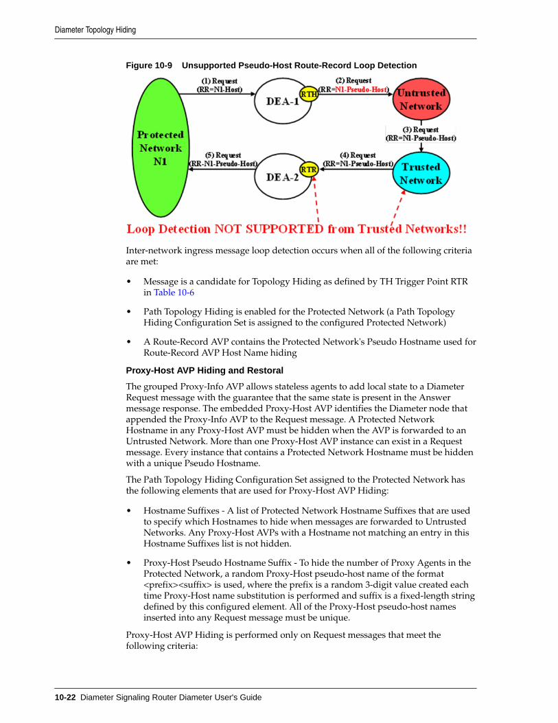
Figure 10-9 Unsupported Pseudo-Host Route-Record Loop Detection
Inter-network ingress message loop detection occurs when all of the following criteriaare met:
• Message is a candidate for Topology Hiding as defined by TH Trigger Point RTRin Table 10-6
• Path Topology Hiding is enabled for the Protected Network (a Path TopologyHiding Configuration Set is assigned to the configured Protected Network)
• A Route-Record AVP contains the Protected Network's Pseudo Hostname used forRoute-Record AVP Host Name hiding
Proxy-Host AVP Hiding and Restoral
The grouped Proxy-Info AVP allows stateless agents to add local state to a DiameterRequest message with the guarantee that the same state is present in the Answermessage response. The embedded Proxy-Host AVP identifies the Diameter node thatappended the Proxy-Info AVP to the Request message. A Protected NetworkHostname in any Proxy-Host AVP must be hidden when the AVP is forwarded to anUntrusted Network. More than one Proxy-Host AVP instance can exist in a Requestmessage. Every instance that contains a Protected Network Hostname must be hiddenwith a unique Pseudo Hostname.
The Path Topology Hiding Configuration Set assigned to the Protected Network hasthe following elements that are used for Proxy-Host AVP Hiding:
• Hostname Suffixes - A list of Protected Network Hostname Suffixes that are usedto specify which Hostnames to hide when messages are forwarded to UntrustedNetworks. Any Proxy-Host AVPs with a Hostname not matching an entry in thisHostname Suffixes list is not hidden.
• Proxy-Host Pseudo Hostname Suffix - To hide the number of Proxy Agents in theProtected Network, a random Proxy-Host pseudo-host name of the format<prefix><suffix> is used, where the prefix is a random 3-digit value created eachtime Proxy-Host name substitution is performed and suffix is a fixed-length stringdefined by this configured element. All of the Proxy-Host pseudo-host namesinserted into any Request message must be unique.
Proxy-Host AVP Hiding is performed only on Request messages that meet thefollowing criteria:
Diameter Topology Hiding
10-22 Diameter Signaling Router Diameter User's Guide

• Message is a candidate for Topology Hiding as defined by TH Trigger Point RTHin Table 10-6
• At least one of the Proxy-Host AVPs contains a Protected Network's Hostname
• Path Topology Hiding is enabled for the Protected Network (a Path TopologyHiding Configuration Set is assigned to the Protected Network)
An example of Proxy-Host AVP Hiding for a Request message initiated by a ProtectedNetwork to an Untrusted Network is shown in Figure 10-10.
Figure 10-10 Proxy-Host Hiding
Because the Proxy-Info AVP is used by stateless agents to store local transaction stateinformation into a Request message and retrieve that information from the Answerresponse, it is important that the DEA restore the original Proxy-Host AVP values(received in the original Request message) when it forwards the Answer responsemessage. Thus, any Proxy-Host AVP value that is replaced at TH Trigger Point RTHmust be saved in its respective Diameter Routing Function PTR.
Proxy-Host AVP Restoral is performed only on Answer messages that meet thefollowing criterion:
• At TH Trigger Point ATR, the Restore Proxy-Host AVPs flag in the PTR associatedwith the Answer message is set to Enabled.
When the criterion is met, Proxy-Host AVP Restoral is performed. The DiameterRouting Function replaces every Proxy-Host AVP value that matches a Proxy-HostPseudo Hostname (stored in the PTR) with the original Hostname (also stored in thePTR).
Error Reporting Host AVP Hiding
The Error-Reporting-Host AVP contains the identity of the Diameter node that set theResult-Code AVP to a value other than 2001 (Success), only if the host setting theResult-Code is different from the one encoded in the Origin-Host AVP.
From a Topology Hiding perspective, the Hostname in this AVP must be hidden if itcontains a Protected Network Hostname and is being sent to an Untrusted Network.
The content of this AVP is hidden using encryption. Troubleshooters in the ProtectedNetwork must have the ability to decrypt the value. Topology Hiding uses AdvancedEncryption Standard (AES), which is described in Encryption.
Although unlikely, more than one Error-Reporting-Host AVP could exist in an Answermessage; each Error-Reporting-Host AVP containing a Protected Network's Hostnamemust be encrypted.
Diameter Topology Hiding
Diameter Topology Hiding 10-23

Error-Reporting-Host AVP Hiding is performed only on Answer messages that meetthe following criteria:
• Message is a candidate for Topology Hiding as defined by topology Trigger PointATH in Table 10-6
• At least one of the Error-Reporting-Host AVPs contains a Protected Network'sHostname
• Path Topology Hiding is enabled for the Protected Network (a Path TopologyHiding Configuration Set is assigned to the Protected Network)
An example of Error-Reporting-Host AVP Hiding for an Answer message receivedfrom a Protected Network that is being forwarded to an Untrusted Network is shownin Figure 10-11.
Figure 10-11 Error-Reporting-Host AVP Hiding
The Path Topology Hiding Configuration Set assigned to the Protected Network hasthe following elements that are used for Error-Reporting-Host Topology Hiding:
• Hostname Suffixes - A list of Protected Network Hostname Suffixes that are usedto specify which host names to hide when messages are forwarded to UntrustedNetworks. Any Error-Reporting-Host AVPs with a Hostname not matching anentry in this Hostname Suffixes list is not hidden.
• Error-Reporting-Host Encryption Key - User-configured encryption key that mustbe used for encrypting the Error-Reporting-Host AVP value. A user-configuredencryption key allows the Error-Reporting-Host AVP value to be decrypted introubleshooting, if required.
S6a/S6d HSS Topology Hiding
S6a/S6d HSS Topology Hiding is concerned with hiding the identities of a ProtectedNetwork's HSS when it exchanges messages with Untrusted Networks. An HSS's hostname is embedded in the Origin-Host and Session-Id AVPs sent in Request messagesand the Origin-Host AVP sent in Answer messages. This capability is associated withthe Diameter S6a/S6d application message set defined in 3GPP TS 29.272, MobilityManagement Entity (MME) and Serving GPRS Support Node (SGSN) relatedinterfaces based on Diameter protocol.
S6a/S6d HSS Topology Hiding determines which entity (HSS or MME/SGSN)initiated a message based on the Command Code in the message.
HSS identities are hidden by replacing the Hostname portion of the Origin-Host andSession-Id AVPs (Session-Id format: <host name><implementation portion>) with anoperator-defined HSS Pseudo Hostname that is assigned to the Protected Network inthe S6a/S6d HSS Topology Hiding Configuration Set.
Protected-HSS to Untrusted-MME/SGSN Transactions
For Protected-HSS to Untrusted-MME/SGSN Diameter transactions, S6a/S6d HSSTopology Hiding is concerned with the following topology information hiding andrestoral issues:
Diameter Topology Hiding
10-24 Diameter Signaling Router Diameter User's Guide

• The AVPs containing an HSS's Actual Hostname in Request messages must behidden with the single HSS Pseudo Hostname assigned to the Protected Networkat TH Trigger Point RTH.
• The MME/SGSN sends an Answer response to the transaction with the Session-Idreceived in the Request (which also contains an HSS Pseudo Hostname). Becausethe Session-Id value returned in the Answer must match the value sent in theRequest, the HSS Pseudo Hostnames in the Answer message Session-Id AVP mustbe restored with the HSS Hostname or Hostnames sent in the Request message.
The Session-Id AVP values are restored at TH Trigger Point ATR, from theHostname portion of the Session-Id AVP value that is saved in the PendingTransaction Record (PTR).
The Hostname restoral procedure is not required for Answers initiated by internalnodes (Diameter Routing Function and applications) as these Answer responsesare based upon the original Request message content and thus do not containPseudo Hostnames.
If a single S6a/S6d pseudo-hostname per S6a/S6d HSS TH Configuration Set is used,then that pseudo-hostname is used for hiding actual S6a/S6d host name. If multiplepseudo-names per actual host-name are used, then contents of User-Name AVP areused to select pseudo-host. In S6a/S6d, subscriber's IMSI is carried in the User-NameAVP. The content of the User-Name AVP content may be one of the following forms:
• IMSI
• IMSI@realm
It is not necessary to extract the IMSI portion from the User-Name AVP value. TheUser-Name AVP value content is the same in all transactions associated withsubscriber. Therefore, the algorithm for mapping actual S6a/S6d HSS host name toone of the pseudo-names assigned to the S6a/S6d HSS is as follows:
• Pseudo-Host Name Selected = Function (User-Name AVP Content) MODULO(Number of Pseudo-Host Names assigned to this S6a/S6d HSS Host Name)
An example of a Protected-HSS to Untrusted-MME/SGSN Diameter transaction isshown in Figure 10-12.
Figure 10-12 S6a/S6d HSS TH Protected-HSS to Untrusted-MME/SGSN DiameterTransaction
For Protected-HSS to Untrusted-MME/SGSN transactions, S6a/S6d HSS topologyinformation hiding is required only on Request messages that meet the followingcriteria:
Diameter Topology Hiding
Diameter Topology Hiding 10-25

• Message was a candidate for Topology Hiding as defined by TH Trigger PointRTH in Table 10-6
• S6a/S6d HSS Topology Hiding is enabled for the Protected Network (an S6a/S6dHSS Topology Hiding Configuration Set is assigned to the Protected Network)
• The Request message is a member of the S6a/S6d message set and was initiatedby an HSS as determined from the Command Code in the message
For Protected-HSS to Untrusted-MME/SGSN transactions, S6a/S6d HSS topologyinformation hiding is performed only on Answer messages that meet the followingcriterion:
• At TH Trigger Point ATR, the S6a/S6d HSS TH ATR flag in the PTR associatedwith the Answer message is set to Enabled.
When the above criterion is met, Session-Id AVP restoral is performed using the HSS'sActual Hostname stored in the PTR.
Untrusted-MME/SGSN to Protected-HSS Transactions
For Untrusted-MME/SGSN to Protected-HSS Diameter transactions, S6a/S6d HSS THis concerned with the following topology information hiding and restoral issue:
• The Destination-Host AVP contains an S6a/S6d HSS pseudo-host name. If a singlepseudo-name is assigned in S6a/S6d HSS TH Configuration Set, then no restoralof the Destination-Host is done by TH (instead the operator can deploy hostResolution Application such as RBAR/FABR). If a single pseudo-name is notassigned per S6a/S6d HSS Configuration Set and instead a unique pseudo-nameis assigned per actual S6a/S6d HSS name, then the pseudo-host name must bereplaced with the S6a/S6d HSS actual-host name at TH trigger point RTR.
An Untrusted-MME/SGSN to Protected-HSS Request message may not containan S6a/S6d HSS pseudo-host name. If the Destination-Host AVP value does notmatch an entry in the TH Pseudo-Host Name, then no host name conversion isrequired and the Request message is routed as normal. The Destination-Hostname conversion is performed to prevent the following problems:
– Certain S6a/S6d HSSs do not accept messages that do not contain its actualhost name
– Diameter outing problems associated with pseudo-host names. For example,DRL Implicit Routing currently only works with actual host names (forexample, the FQDN assigned to the Peer Node and used for the CapabilitiesExchange procedure [CER/CEA])
• The S6a/S6d HSS-initiated Answer response contains an actual S6a/S6d HSS hostname in the Origin-Host AVP. This must be hidden with the S6a/S6d HSS pseudo-host name assigned to the Protected Network at TH trigger point ATH.
For Untrusted-MME/SGSN to Protected-HSS transactions, S6a/S6d HSS topologyinformation hiding is required only on Answer messages that meet the followingcriteria:
• Message was a candidate for Topology Hiding as defined by topology TriggerPoint ATH in Table 10-6
• S6a/S6d HSS Topology Hiding is enabled for the Protected Network (an S6a/S6dHSS Topology Hiding Configuration Set is assigned to the Protected Network)
Diameter Topology Hiding
10-26 Diameter Signaling Router Diameter User's Guide

• The Answer message is a member of the S6a/S6d message set and was initiatedby an HSS as determined from the Command Code in the message
Restoral of a Protected-HSS's actual-host name in the Untrusted-MME/SGSN toProtected-HSS Request message is not performed by topology hiding if a singlepseudo-name is used in S6a/S6d HSS TH Configuration Set assigned to a protectednetwork. Instead, this replacement function is required of a HSS Address Resolutionapplication such as FABR or RBAR applications.
HSS
An example of an Untrusted-MME/SGSN to Protected-HSS Diameter transaction isshown in Figure 10-13 and when pseudo-name per S6a/S6d HSS host name inS6a/S6d HSS TH Configuration Set.
Figure 10-13 S6a/S6d HSS TH Untrusted-MME/SGSN to Protected-HSS Transaction
Figure 10-14 S6a/S6d HSS TH Untrusted-MME/SGSN to Protected-HSS Transaction
Restoral of a Protected-HSS's actual-host name in the Untrusted-MME/SGSN toProtected-HSS Request message is performed by topology hiding if a unique pseudo-name is assigned per S6a/S6d HSS host name in S6a/S6d HSS TH Configuration Set.
For Untrusted-HSS to Protected-MME/SGSN transactions, S6a/S6d HSS topologyhiding is only invoked on Request messages which meet the following criteria:
• Message was a candidate for topology hiding as defined by topology trigger pointRTR
• S6a/S6d HSS TH is enabled for the Protected Network (S6a/S6d HSS THConfiguration Set is assigned to the Protected Network)
• The Request message is a member of the S6a/S6d message set and was initiatedby an MME/SGSN
Diameter Topology Hiding
Diameter Topology Hiding 10-27

• The Destination-Host AVP contains an S6a/S6d HSS pseudo-host name that isassigned to the Protected Network as determined from the internal S6a/S6d HSSTH Pseudo-Host Name
MME/SGSN Topology Hiding
MME/SGSN Topology Hiding is concerned with hiding the identity of a ProtectedHome Network's MME/SGSNs and the number of MME/SGSNs in the network,when it exchanges messages with Untrusted Networks. A MME/SGSN's identity isembedded in the Origin-Host and Session-ID AVPs sent in Request messages and inthe Origin-Host AVP sent in Answer messages. MME/SGSN Topology Hiding isassociated with the Diameter S6a/S6d application message set defined in 3GPP TS29.272, Mobility Management Entity (MME) and Serving GPRS Support Node (SGSN)related interfaces based on Diameter protocol.
MME/SGSN Topology Hiding determines which entity (HSS or MME/SGSN)initiated an S6a/S6d message based on the Command Code in the message.
MME/SGSN identities are hidden by replacing the Actual Hostname portion of theOrigin-Host and Session-ID AVPs (Session-ID format: <host name><implementationportion>) with an MME/SGSN Pseudo Hostname. The Origin-Host and Session-IDAVPs can have different MME/SGSN Hostnames. A unique Pseudo Hostname mustbe created for each MME/SGSN in a Protected Network. When the MME/SGSNinitiates a transaction to the HSS, the HSS saves the MME/SGSN's identity for use insubsequent HSS-to-MME/SGSN transactions. This MME/SGSN Pseudo Hostnamemust not only be unique, but the DEA must be able to convert the MME/SGSN'sPseudo Hostname to an Actual MME/SGSN Hostname for these subsequent HSS-to-MME/SGSN transactions.
To hide the number of MME/SGSNs in a network, each MME/SGSN is assignedeither a random or fixed number of Pseudo Hostnames. A maximum number isdefined by the Count in the Pseudo Hostname Generation attribute of the MME/SGSN Topology Hiding Configuration Set. The Randomize Count creates a randomnumber of Pseudo Hostnames, between 1 and the Count value, that are associatedwith an Actual Hostname. This procedure of creating randomized MME/SGSNPseudo Hostnames and assigning them to an Actual Pseudo Hostname is performedby the GUI, then used by the Diameter Routing Function. The created MME/SGSNTH Hostnames allow the Diameter Routing Function to map a Protected-MME/SGSNActual Hostname to a set of MME/SGSN Pseudo Hostnames, and to map a MME/SGSN Pseudo Hostname received from an Untrusted-HSS to a Protected-MME/SGSNActual Hostname.
Table 10-16 shows an example of MME/SGSN TH Host Names configuration for aProtected Network with a maximum of 3 randomly created Pseudo Hostnames.
Table 10-16 Example of Configuration of MME/SGSN TH Hostnames for a ProtectedNetwork
MME/SGSN TH ConfigurationSet Name
MME/SGSN ActualHostname
MME/SGSN PseudoHostnames
Protected Network-1 MME/SGSN Config
mme1.westregion.example.com
mme042.example.com
mme821.example.com
Protected Network-1 MME/SGSN Config
mme1.westregion.example.com
mme123.example.com
Diameter Topology Hiding
10-28 Diameter Signaling Router Diameter User's Guide

Table 10-16 (Cont.) Example of Configuration of MME/SGSN TH Hostnames for aProtected Network
MME/SGSN TH ConfigurationSet Name
MME/SGSN ActualHostname
MME/SGSN PseudoHostnames
Protected Network-1 MME/SGSN Config
mme2.westregion.example.com
mme533.example.com
mme773.example.com
mme092.example.com
Protected Network-1 MME/SGSN Config
mme1.eastregion.example.com
mme922.example.com
mme729.example.com
Protected Network-1 MME/SGSN Config
mme2.eastregion.example.com
mme411.example.com
mme002.example.com
mme655.example.com
Protected Network-1 MME/SGSN Config
mme2.eastregion.example.com
mme218.example.com
Protected Network-1 MME/SGSN Config
mme2.eastregion.example.com
mme331.example.com
mme249.example.com
mme447.example.com
Protected Network-1 MME/SGSN Config
mme1.texasregion.example.com
mme776.example.com
mme077.example.com
Protected Network-1 MME/SGSN Config
mme1.texasregion.example.com
mme295.example.com
mme622.example.com
mme861.example.com
Protected Network-1 MME/SGSN Config
mme1.texasregion.example.com
mme333.example.com
Protected-MME/SGSN to Untrusted-HSS Transactions
For Protected-MME/SGSN to Untrusted-HSS Diameter transactions, MME/SGSNTopology Hiding is concerned with the following topology information hiding andrestoral issues:
• The AVPs containing an MME/SGSN's Actual Hostname in Request messagesmust be hidden with one of the Pseudo Hostnames assigned to the MME/SGSNat TH Trigger Point RTH.
• The HSS saves the subscriber's location using the Origin-Host AVP contentscontaining a Pseudo Hostname. In subsequent HSS-to-MME/SGSN transactions,the MME/SGSN is addressed by one of its Pseudo Hostnames, requiring aPseudo-to-Actual Hostname restoral.
• All MME/SGSN-to-HSS transactions associated with a particular subscriber mustuse the same MME/SGSN Pseudo Hostname. Otherwise, the HSS thinks thesubscriber has moved to another MME/SGSN and unnecessarily changes thesubscriber's location. For S6a/S6d transactions, the subscriber associated with thetransaction is identified by an IMSI, which for the S6a/S6d message set isembedded in the User-Name AVP, a mandatory AVP in all MME/SGSN-to-HSSRequest messages.
Diameter Topology Hiding
Diameter Topology Hiding 10-29

Note: Although the Origin-Host and Session-ID AVPs both have MME/SGSNActual Hostnames, the names could be different. Because the HSS associatesthe MME/SGSN's location based on the Origin-Host AVP content, it is theMME/SGSN Actual Hostname in the Origin-Host AVP that must be used forselecting a MME/SGSN Pseudo Hostname. This MME/SGSN PseudoHostname can be used to replace both of the Hostname fields in the forwardedRequest message.
• The HSS sends an Answer response to the transaction with the Session-IDreceived in the Request and containing an MME/SGSN Pseudo Hostname.Because the Session-ID value returned in the Answer must match the value in theRequest, the MME/SGSN Pseudo Hostname in the Session-ID AVP must bereplaced with its corresponding value received in the Request message. The valueis restored at TH Trigger Point ATR, with the Hostname portion of the Session-IDAVP value that is stored in the PTR.
This Hostname restoral procedure is not required for Answers initiated bydiameter internal nodes (the Diameter Routing Function and applications) asthese Answer responses are based upon the original Request message content.
An example of a Protected-MME/SGSN to Untrusted-HSS Diameter transaction isshown in Figure 10-15.
Figure 10-15 MME/SGSN TH Protected-MME/SGSN to Untrusted HSS Transaction
In S6a/S6d, the subscriber's IMSI is carried in the User-Name AVP. The content of theUser-Name AVP content can be one of the following forms:
• IMSI
• IMSI@realm
It is not necessary to extract the IMSI portion from the User-Name AVP value. TheUser-Name AVP value content is the same in all transactions associated withsubscriber.
For Protected-MME/SGSN to Untrusted-HSS transactions, S6a/S6d HSS TopologyHiding is required only on Request messages that meet the following criteria:
• Message was a candidate for Topology Hiding as defined by topology TriggerPoint RTH in Table 10-6
• MME/SGSN Topology Hiding is enabled for the Protected Network (an MME/SGSN TH Configuration Set is assigned to the Protected Network)
• The Request message is a member of the S6a/S6d message set and was initiatedby an MME/SGSN as determined from the Command Code in the message
Diameter Topology Hiding
10-30 Diameter Signaling Router Diameter User's Guide

• The Origin-Host and/or Session-ID AVPs in the Request contain an MME/SGSNActual Hostname assigned to the Protected Network in its MME/SGSN TopologyHiding Configuration Set.
For Protected-MME/SGSN to Untrusted-HSS transactions, MME/SGSN topologyinformation restoral is performed only on Answer messages that meet the followingcriterion:
• At TH Trigger Point ATR, the MME/SGSN TH ATR flag in the PTR associatedwith the Answer message is set to Enabled.
Untrusted-HSS to Protected-MME/SGSN Transactions
When an Untrusted-HSS initiates a transaction to a Protected-MME/SGSN, it istypically addressed to one of the MME/SGSN's Pseudo Hostnames that the HSS savedin a previous MME/SGSN-to-HSS transaction for which MME/SGSN TopologyHiding was applied. For Untrusted-HSS to Protected-MME/SGSN Diametertransactions, MME/SGSN Topology Hiding is concerned with the following topologyinformation hiding and restoral issues:
• The Destination-Host AVP contains a MME/SGSN Pseudo Hostname that mustbe replaced with the MME/SGSN's Actual Hostname at TH Trigger Point RTR.Pseudo-to-Actual Hostname mapping is performed using the list of createdMME/SGSN TH Hostnames described in MME/SGSN Topology Hiding. It isacceptable that an Untrusted-HSS to Protected-MME/SGSN Request messagedoes not contain a MME/SGSN Pseudo Hostname. If the Destination-Host AVPvalue does not match an entry in the MME/SGSN TH Host Names list, then noHostname conversion is required and the Request message is routed normally.Destination-Hostname conversion is performed to prevent the followingproblems:
• Certain MME/SGSNs do not accept messages that do not contain its ActualHostname.
• Diameter routing problems associated with Pseudo Hostnames. For example,Diameter Implicit Routing works only with Actual Hostnames (such as the FQDNassigned to the Peer Node and used for the Capabilities Exchange procedure[CER/CEA]).
Note: For local nodes, CEAs are sent in response to erroneous CERs.
• An Origin-Host AVP containing an MME/SGSN's Actual Hostname in theAnswer response from the Protected-MME/SGSN must be hidden with one of thePseudo Hostnames assigned to that MME/SGSN. This is done at TH Trigger PointATH.
An example of an Untrusted-HSS to Protected-MME/SGSN Diameter transaction isshown in Figure 10-16.
Figure 10-16 MME/SGSN TH Untrusted-HSS to Protected MME/SGSN Transaction
Diameter Topology Hiding
Diameter Topology Hiding 10-31

For Untrusted-HSS to Protected-MME/SGSN transactions, S6a/S6d HSS TopologyHiding is invoked only on Request messages that meet the following criteria:
• Message was a candidate for topology Hiding as defined by TH Trigger Point RTRin Table 10-6
• MME/SGSN Topology Hiding is enabled for the Protected Network (an MME/SGSN Topology Hiding Configuration Set is assigned to the Protected Network)
• The Request message is a member of the S6a/S6d message set and was initiatedby an MME/SGSN as determined from the Command Code in the message
• The Destination-Host AVP contains a MME/SGSN Pseudo Hostname that isassigned to the Protected Network as determined from the list of created MME/SGSN TH Host Names described in MME/SGSN Topology Hiding.
For Untrusted-HSS to Protected-MME/SGSN transactions, S6a/S6d HSS TopologyHiding is invoked only on Answer messages at TH Trigger Point ATH that meet thefollowing criteria:
• Message was a candidate for Topology Hiding as defined by topology TriggerPoint ATH in Table 10-6
• MME/SGSN Topology Hiding is enabled for the Protected Network (an MME/SGSN Topology Hiding Configuration Set is assigned to the Protected Network)
• The Answer message is a member of the S6a/S6d message set and was initiatedby an MME/SGSN as determined from the Command Code in the message
• The Origin-Host AVP contains an MME/SGSN Actual Hostname that is assignedto the Protected Network in its MME/SGSN Topology Hiding Configuration Set.
S9 PCRF Topology Hiding
S9 PCRF Topology Hiding is concerned with hiding the identities of a ProtectedNetwork's PCRFs, as well as the number of PCRFs in the network, when it exchangesmessages with Untrusted Networks. A PCRF's identity is embedded in the Origin-Host and Session-ID AVPs sent in Request messages and the Origin-Host AVP sent inAnswer messages. This capability (and S9 AF/pCSCF Topology Hiding) is associatedwith the Diameter S9 and Rx application message set.
S9 PCRF topology hiding is concerned with all S9 messages and Rx messages whenAF/pCSCF is deployed in client/server mode. If the PCRF is deployed in client/server mode for Rx messages, then S9 AF/pCSCF TH Configuration Set should not beenable for the protected network.
Note: All S9 messages initiated by hPCRF or vPCRF have S9 PCRF TopologyHiding applied (if enabled). If S9 AF/pCSCF TH is not enabled, then all Rxmessages initiated by hPCRF or vPCRF have S9 PCRF Topology Hidingapplied (if enabled). If S9 AF/pCSCF TH is enabled (i.e., if vPCRF is proxyingAF/pCSCF messages to hPCRF), then only AAA/STA/RAR and ASR Rxmessages have PCRF TH applied.
PCRF identities are hidden by replacing the actual host name portion of the Origin-Host and Session-ID AVPs with a PCRF pseudo-host name. The Origin-Hose andSession-ID AVPs may have different PCRF host names. A unique pseudo- name mustbe created for each PCRF in a Protected Network. When the vPCRF initiates a
Diameter Topology Hiding
10-32 Diameter Signaling Router Diameter User's Guide

transaction to the hPCRF, the hPCRF saves the vPCRF's identity for use in subsequenthPCRF-to-vPCRF transactions. This vPCRF pseudo-host name must not only beunique, but the DEA must be able to convert the vPCRF's pseudo-name to an actualvPCRF host name for these subsequent hPCRF to vPCRF transactions.
To hide the number of PCRFs in a network, each PCRF is assigned either a random orfixed number of pseudo-host names (the maximum is defined by an S9 PCRF THConfiguration Set attribute called Maximum Pseudo-Host Names per PCRF). The GUIcreates the randomized PCRF pseudo-host names and assign them to actual pseudo-host names to be used by DRL. The TH Host Names allows DRL to map a Protected-PCRF actual-host name to a set of PCRF pseudo-host names as well as map a PCRFpseudo-host named received from an Untrusted Network to a Protected-PCRF actual-host name.
Protected-vPCRF to Untrusted-hPCRF Transactions
When vPCRF is in a Protected Network, S9 Diameter sessions are initiated by vPCRFin a Protected Network on behalf of an inbound roamer to request PCC or QoS rules tothe hPCRF.
When AF/pCSCF and PCRF are in a Protected Network and AF/pCSCF uses vPCRFin client/server mode to communicate Rx messages initiated by vAF/pCSCF tohPCRF in an Untrusted network, then S9 PCRF TH is used to hide PCRF host names toan Untrusted Network.
For Protected-vPCRF to Untrusted-hPCRF S9 Diameter transactions, S9 PCRF TH isconcerned with the following topology information hiding and restoral issues:
• The AVPs containing a PCRF's actual-host name in Request messages must behidden with one of the pseudo-host names assigned to the PCRF at TH triggerpoint RTH
• The Untrusted network's PCRF (hPCRF in this case) saves the subscriber's locationusing the Origin-Host AVP contents containing a pseudo-host name. This has thefollowing impact:
– In subsequent hPCRF-vPCRF transactions(e.g RAR/ASR), the vPCRF may beaddressed by one of its pseudo-host names requiring a pseudo-to-actual namerestoral
– All vPCRF-to-hPCRF transactions associated with a particular session mustuse the same vPCRF pseudo-host name. The Session is identified by Session-ID AVP, a mandatory AVP in all S9/Rx messages.
Note: Although the Origin-Host and Session-ID AVPs both have actual PCRFhost names, they may be different. Because S9/Rx is a session basedapplication , actual PCRF host names must be restored in subsequent hPCRF-vPCRF transactions. Hence both Origin-Host and Session-ID AVPs must beselected from Actual Host Names in S9 PCRF TH.
• The hPCRF sends an Answer response to the transaction with the Session-IDreceived in the Request (also containing a PCRF pseudo-host name). Because theSession-ID value returned in the Answer must match the Request, the PCRFpseudo-host name in the Session-ID AVP must be replaced with its correspondingvalue received in the Request message. This value is restored at TH trigger pointATR. This requires saving the host name portion of the Session-ID AVP value inthe PTR. This host name restoral procedure is not required for Answers initiated
Diameter Topology Hiding
Diameter Topology Hiding 10-33

by internal nodes as these Answer responses are based upon the original Requestmessage content
An example of a Protected-vPCRF to Untrusted-hPCRF Diameter transaction is shownin Figure 10-17.
Figure 10-17 Protected-vPCRF to Untrusted-hPCRF Transaction
To ensure all S9/Rx messages for the same session are modified using the samepseudo-name, the Session-ID AVP can be used as a key to select a Pseudo Host Namefor an Actual Host Name.
Untrusted-hPCRF to Protected-vPCRF Transactions
For Protected-vPCRF to Untrusted-hPCRF S9/Rx transactions, PCRF topology hidingis only required on Request messages which meet the following criteria:
• The message was a candidate for topology hiding as defined by topology triggerpoint RTH and
• S9 PCRF TH is enabled for the Protected network (S9 PCRF TH Configuration Setis assigned to the Protected Network) and
• The Request message is a member of the S9 message and was initiated by a PCRFor
• The Request message is a member of the Rx message set and was initiated by aPCRF and S9 AF/pCSCF TH is not enabled and
• The Origin-Host and/or Session-ID AVPs in the Request contain an actual PCRFhost name assigned to the Protected Network via the S9 PCRF Configuration Set.
For Protected-vPCRF to Untrusted-hPCRF transactions, PCRF topology informationrestoral is only performed on Answer messages which meet the following criteria:
• At topology trigger point ATR, the PCRF TH ATR flag in the PTR associated withthe Answer message is set to Enabled.
When an Untrusted-hPCRF initiates a transaction to a Protected-vPCRF, it is mostlikely addressed to one of the vPCRF pseduo-host names that the hPCRF saved in aprevious vPCRF-to-hPCRF transaction for which S9 PCRF TH was applied. ForUntrusted-hPCRF to Protected-vPCRF Diameter transactions (RAR, ASR, and so on),S9 PCRF TG is concerned with the following topology information hiding and restoralissues:
• The Destination-Host AVP contains a vPCRF pseudo-host name. This pseudo-hostname must be replaced with the vPCRF's actual-host name at TH trigger pointRTR. Pseudo-to-actual host name mapping is performed using the internal TH
Diameter Topology Hiding
10-34 Diameter Signaling Router Diameter User's Guide

Host Names. It's perfectly acceptable that an Untrusted-hPCRF to Protected-vPCRF Request message does not contain a PCRF pseudo-host name. If theDestination-Host AVP value does not match an entry in the TH Pseudo-HostName, then no host name conversion is required and the Request message isrouted as normal. Destination-Host name conversion is performed to prevent thefollowing problems:
– Certain vPCRFs do not accept messages that do not contain its actual hostname
– Diameter routing problems associated with pseudo-host names. For example,DRL Implicit Routing currently only works with actual host names (forexample, the FQDN assigned to the Peer Node and used for the CapabilitiesExchange procedure [CER/CEA]).
• The host portion of Session-ID AVP containing a PCRF pseudo-host name must bereplaced back with vPCRF's actual host name at TH trigger point RTR. Pseudo-to-actual host name mapping is performed using the internal TH Host Names.
• An Origin-Host AVP containing a vPCRF's actual-host name in the Answerresponse from the Protected-vPCRF must be hidden with one of the pseudo-hostnames assigned to that PCRF. This procedure is done at TH trigger point ATH.
• Session-ID AVP containing a vPCRF's actual-host name in the Answer responsefrom the Protected-vPCRF must be hidden with one of the pseudo-host namesassigned to that PCRF. This is done at TH trigger point ATH.
An example of an Untrusted-hPCRF to Protected-vPCRF Diameter transaction isshown in Figure 10-18.
Figure 10-18 Untrusted-hPCRF to Protected-vPCRF Diameter Transaction
For Untrusted-hPCRF to Protected-vPCRF transactions, S9 PCRF TH is only invokedon Request messages at topology trigger point RTR which meet the following criteria:
• The message was a candidate for topology hiding as defined by topology triggerpoint RTR and
• S9 PCRF TH is enabled for the Protected Network (S9 PCRF TH Configuration Setis assigned to the Protected Network) and
• The Request message is a member of the S9 message set and was initiated by aPCRF or
• The Request message is a member of Rx message set and was initiated by a PCRFand S9 AF/pCSCF TH is not enabled and
Diameter Topology Hiding
Diameter Topology Hiding 10-35

• The Destination-Host AVP or host portion of Session-ID AVP contains a PCRFpseudo-host name that is assigned to the Protected Network as determined fromthe internal Pseudo-Host Name
For Untrusted-hPCRF to Protected-vPCRF transactions, S9 PCRF HSS topology hidingis only invoked on Answer messages at topology trigger point ATH which meet thefollowing criteria:
• Message was a candidate for topology hiding as defined by topology trigger pointATH
• S9 PCRF TH is enabled for the Protected Network (S9 PCRF TH Configuration Setis assigned to the Protected Network)
• The Answer message is a member of the S9 message set and was initiated by aPCRF or
• The Answer message is a member of Rx message set and was initiated by a PCRFand S9 AF/pCSCF TH is not enabled and
• The Origin-Host AVP or host portion of Session-ID AVP contains an actual PCRFhost name that is assigned to the Protected Network via the S9 PCRF THConfiguration Set
Protected-hPCRF to Untrusted-vPCRF Transactions
When an hPCRF is in Protected Network, S9 Diameter sessions are initiated by avPCRF in an Untrusted Network on behalf of an outbound roamer to request PCC orQoS rules to the hPCRF. hPCRF can send RAR in the session initiated by vPCRF.
When AF/pCSCF and PCRF is in an Untrusted network and AF/pCSCF uses vPCRFin client/server mode to communicate Rx messages initiated by vAF/pCSCF tohPCRF in a Protected Network, then S9 PCRF TH is used to hide PCRF host namesfrom an Untrusted Network. hPCRF can send RAR or ASR messages in the sessionintiated vPCRF.
For Protected-hPCRF to Untrusted-vPCRF S9 Diameter transactions, S9 PCRF TH isconcerned with the following topology information hiding and restoral issues:
• S9 Sessions are initiated from untrusted network using CCR and Rx Sessions areinitiated from untrusted network using AAR. Hence the host portion of Session-ID AVP contains the host of the untrusted network, which does not need to behidden.
• The Origin-Host AVP containing an PCRF's actual-host name in Request messagesmust be hidden with one of the pseudo-host names assigned to the PCRF at THtrigger point RTH.
An example of a Protected-hPCRF to Untrusted-vPCRF Diameter transaction is shownin Figure 10-19.
Diameter Topology Hiding
10-36 Diameter Signaling Router Diameter User's Guide

Figure 10-19 Protected-hPCRF to Untrusted-vPCRF Transaction
To ensure all S9/Rx messages for same session are modified using same pseudo-name , Session-ID AVP can be used as key to select a Pseudo Host Name for an ActualHost Name.
For Protected-hPCRF to Untrusted-vPCRF S9/Rx transactions, PCRF topology hidingis only required on Request messages which meet the following criteria:
• The message was a candidate for topology hiding as defined by topology triggerpoint RTH and
• S9 PCRF TH is enabled for the Protected Network (S9 PCRF TH Configuration Setis assigned to the Protected Network) and
• The Request message is a member of the S9/Rx message set and was initiated by aPCRF and
• The Origin-Host AVP in the Request contain an actual PCRF host name assignedto the Protected Network via the S9 PCRF TH Configuration Set
Untrusted-vPCRF to Protected-hPCRF Transactions
When an Untrusted-vPCRF initiates a transaction to a Protected-hPCRF, it is mostlikely addressed to one of the hPCRF pseudo-host names that the vPCRF saved in aprevious hPCRF-to-vPCRF transaction for which PCRF TH was applied. ForUntrusted-vPCRF to Protected-hPCRF Diameter transactions (CCR, AAR/STR, and soon), PCRF TH is concerned with the following topology information hiding andrestoral issues:
• The Destination-Host AVP contains a PCRF pseudo-host name. This pseudo-hostname must be replaced with the hPCRF's actual-host name at TH trigger pointRTR. Pseudo-to-actual host name mapping is performed using the internal THHost Names table. It's perfectly acceptable that an Untrusted-vPCRF to Protected-hPCRF Request message does not contain a PCRF pseudo-host name. If theDestination-Host AVP value does not match an Pseudo-Host Name entry in theTH Host Names, then no host name conversion is required and the Requestmessage is routed as normal. Destination-Host name conversion is performed toprevent the following problems:
– Certain hPCRFs do not accept messages that do not contain its actual hostname
– Diameter routing problems associated with pseudo-host names. For example,DRL Implicit Routing currently only works with actual host names (i.e., theFQDN assigned to the Peer Node and used for the Capabilities Exchangeprocedure (CER/CEA))
Diameter Topology Hiding
Diameter Topology Hiding 10-37

• An Origin-Host AVP containing an vPCRF's actual-host name in the Answerresponse from the Protected-hPCRF must be hidden with one of the pseudo-hostnames assigned to that PCRF . This is done at TH trigger point ATH.
An example of an Untrusted-vPCRF to Protected-hPCRF Diameter transaction isshown in Figure 10-20.
Figure 10-20 Untrusted-vPCRF to Protected-hPCRF Transaction
For Untrusted-vPCRF to Protected-hPCRF transactions, S9 PCRF HSS topology hidingis only invoked on Request messages at topology trigger point RTR which meet thefollowing criteria:
• Message was a candidate for topology hiding as defined by topology trigger pointRTR and
• S9 PCRF TH is enabled for the Protected Network (S9 PCRF TH Configuration Setis assigned to the Protected Network) and
• The Request message is a member of the S9 message set and was initiated by aPCRF as determined and
• The Request message is a member of Rx message set and was initiated by a PCRFand S9 AF/pCSCF TH is not enabled and
• The Destination-Host AVP contains a PCRF pseudo-host name that is assigned tothe Protected Network as determined from the internal Pseudo-Host Name
For Untrusted-vPCRF to Protected-hPCRF transactions, S9 PCRF HSS topology hidingis only invoked on Answer messages at topology trigger point ATH which meet thefollowing criteria:
• Message was a candidate for topology hiding as defined by topology trigger pointATH
• S9 PCRF TH is enabled for the Protected Network (S9 PCRF TH Configuration Setis assigned to the Protected Network)
• The Answer message is a member of the S9 message set and was initiated by aPCRF
• The Origin-Host AVP contains an actual PCRF host name that is assigned to theProtected Network via the S9 PCRF TH Configuration Set
S9 AF/pCSCF Topology Hiding
S9 AF/pCSCF Topology Hiding is concerned with hiding the identities of a ProtectedNetwork's AF/pCSCFs, as well as the number of AF/pCSCFs in the network, when itexchanges messages with Untrusted Networks. An AF/pCSCF identity is embedded
Diameter Topology Hiding
10-38 Diameter Signaling Router Diameter User's Guide

in the Origins-Host and Session-ID AVPs sent in Request messages and the Origin-Host AVP sent in Answer messages. This capability is associated with the Diameter Rxapplication message set.
S9 AF/pCSCF topology hiding is concerned with Rx messages when AF/pCSCF isdeployed in proxy mode. If PCRF is deployed in client/server mode for Rx messages,then S9 AF/pCSCF TH Configuration Set should be enabled for the protectednetwork. If S9 AF/pCSCF TH is enabled (for example, if vPCRF is proxying AF/pCSCF messages to hPCRF), then only AAR/STR and RAA/ASA have S9 PCRF THapplied.
AF/pCSCF identities are hidden by replacing the actual host name portion of theOrigin-Host and Session-ID AVPs with AF/pCSCF pseudo-host name. The Origin-Host and Session-ID AVPs may have different AF/pCSCF host names. A uniquepseudo name must be created for each AF/pCSCF in a Protected Network. When thevAF/pCSCF initiates a transaction to the hPCRF, the hPCRF saves the vAF/pCSCF'sidentity for use in subsequent hPCRF-to-vAF/pCSCF transactions. This vAF/pCSCF'spseudo-host name must not only be unique, but the DEA must be able to convert thevAF/pCSCF's pseudo-name to an actual vAF/pCSCF host name for these subsequenthPCRF to vAF/pCSCF transactions.
To hide the number of AF/pCSCFs in a network, each AF/pCSCF is assigned either arandom or fixed number of pseudo-host names (the maximum is defined by an S9AF/pCSCF TH Configuration Set attribute called Maximum Pseudo-Host Names perAF/pCSCF). This procedure of creating randomized AF/pCSCF pseudo-host namesand assigning them to actual pseudo-host names is performed by the GUI and used byDRL. The TH Host Names MO allows DRL to map a Protected-AF/pCSCF actual-hostname to a set of AF/pCSCF pseudo-host names and map an AF/pCSCF pseudo-hostname received from an Untrusted network to a Protected-AF/pCSCF actual-hostname.
Protected-vAF/pCSCF to Untrusted-hPCRF Transactions
When AF/pCSCF and PCRF are in a Protected Network and AF/pCSCF uses vPCRFin proxy mode to communicate Rx messages initiated by vAF/pCSCF to hPCRF inUntrusted Network, then S9 AF/pCSCF TH is used to hide AF/pCSCF host names toUntrusted Network.
For Protected-vAF/pCSCF to Untrusted-hPCRF Rx Diameter transactions, S9 AF/pCSCF TH is concerned with the following topology information and restoral issues:
• The AVPs containing an AF/pCSCF's actual-host name in Request message mustbe hidden with one of the pseudo-host names assigned to the AF/pCSCF at THtrigger point RTH
• The Untrusted Network's PCRF (hPCRF in this case) saves the subscriber'slocation using the Origin-Host AVP contents containing a pseudo-host name. Thisaction has the following impact:
– In subsequent hPCRF-vAF/pCSCF transactions (for example, RAR/ASR), thevAF/pCSCFis addressed by on of its pseudo-host names requiring a pseudo-to-actual name restoral
– All vAF/pCSCF-to-hPCRF transactions associated with a particular sessionmust use the same vAF/pCSCF pseudo-host name. The Session is identifiedby Session-ID AVP, a mandatory AVP in all S9/RX messages.
Diameter Topology Hiding
Diameter Topology Hiding 10-39

Note: Although the Origin-Host and Session-ID AVPs both have actual AF/pCSCF host names, the may be different. Because Rx is a session basedapplication, actual AF/pCSCF host names must be restored in subsequenthPCRF-vAF/pCSCF transactions. Hence the Origin-Host and Session-ID AVPsmust be selected from the Actual Host Names TH Host Names.
• The hPCRF sends an Answer response to the transaction with the Session-IDreceived in the Request (containing an AF/pCSCF pseudo-host name). Becausethe Session-ID value returned in the Answer must match the Request, the AF/pCSCF pseudo-host name in the Session-ID AVP must be replaced with itscorresponding value received in the Request message. This value is restored at THtrigger point ATR. This requires saving the host name portion of the Session-IDAVP value in the PTR. This host name restoral procedure is not required forAnswers initiated by internal nodes as these Answer responses are based uponthe original Request message content.
An example of a Protected-vAF/pCSCF to Untrusted-hPCRF Diameter transaction isshown in Figure 10-21.
Figure 10-21 Protected vAF/pCSCF to Untrusted-hPCRF Transaction
To ensure all Rx messages for the same session are modified using the same pseudo-name, Session-ID AVP can be used as a key to select a Pseudo Host Name for anActual Host Name.
For Protected-vAF/pCSCF to Untrusted-hPCRF Rx transactions, S9 Af/pCSCFtopology hiding is only required on Request messages at topology hiding point RTHwhich meet the following criteria:
• The message was a candidate for topology hiding as defined by topology triggerpoint RTH and
• S9 AF/pCSCF TH is enabled for the Protected Network (S9 PCRF THConfiguration Set is assigned to the Protected Network) and
• The Request message is a member of the Rx message set and was initiated by anAF/pCSCF and
• The Origin-Host and/or Session-ID AVPs in the Request contain an actual AF/pCSCF host name assigned to the Protected Network via the S9 AF/pCSCF THConfiguration Set.
For Protected-vAF/pCSCF to Untrusted-hPCRF transactions, AF/pCSCF topologyinformation restoral is only performed on Answer messages which meet the followingcriterion:
Diameter Topology Hiding
10-40 Diameter Signaling Router Diameter User's Guide

• At TH Trigger Point ATR, the AF/pCSCF TH ATR flag in the PTR associated withthe Answer message is set to Enabled.
Untrusted-hPCRF to Protected-vAf/pCSCF Transactions
When an Untrusted-hPCRF initiates a transaction to a Protected-vAF/pCSCF, it ismost likely addressed to one of the vAF/pCSCF pseudo-host names that the hPCRFsaved in a previous vAF/pCSCF-to-hPCRF transaction for which S9 AF/pCSCF THwas applied. For Untrusted-hPCRF to Protected-vAF/pCSCF Diameter transactions(RAR, ASR, and so on), S9 AF/pCSCF TH is concerned with the following topologyinformation hiding and resotral issues:
• The Destination-Host AVP contains a vAF/pCSCF pseudo-host name. Thispseudo-host name must be replaced with the vAF/pCSCF's actual-host name atTH trigger point RTR. It's perfectly acceptable that an Untrusted-hPCRF toProtected-vAF/pCSCF Request message does not contain a vAF/pCSCF pseudo-host name. If the Destination-Host AVP value does not match a Pseudo-Host entryin the TH Host Name table , then no host name conversion is required and theRequest message is routed as normal. Destination-Host name conversion isperformed to prevent the following problems:
– Certain vAF/pCSCFs do not accept messages that do not contain its actualhost name
– Diameter routing problems associated with pseudo-host names. For example,DRL Implicit Routing currently only works with actual host names (forexample, the FQDN assigned to the Peer Node and used for the CapabilitiesExchange procedure (CER/CEA)).
– The host portion of Session-ID AVP containing a vAF/pCSCF pseudo-hostname must be replaced back with vAF/pCSCF's actual host name at THtrigger point RTR
– An Origin-Host AVP containing an vAF/pCSCF's actual-host name in theAnswer response from the Protected- vAF/pCSCF must be hidden with oneof the pseudo-host names assigned to that vAF/pCSCF. This is done at THtrigger point ATH.
– Session-ID AVP containing an vAF/pCSCF's actual-host name in the Answerresponse from the Protected-vAF/pCSCF must be hidden with one of thepseudo-host names assigned to that vAF/pCSCF. This is done at TH triggerpoint ATH.
An example of an Untrusted-hPCRF to Protected- vAF/pCSCF Diameter transaction isshown in Figure 10-22.
Diameter Topology Hiding
Diameter Topology Hiding 10-41

Figure 10-22 Untrusted-hPCRF to Protected-vAF/pCSCF Transaction
For Untrusted-hPCRF to Protected-vAF/pCSCF transactions, S9 AF/pCSCF TH isonly invoked on Request messages at topology trigger point RTR which meet thefollowing criteria:
• Message was a candidate for topology hiding as defined by topology trigger pointRTR and
• S9 AF/pCSCF TH is enabled for the Protected Network (S9 AF/pCSCF THConfiguration Set is assigned to the Protected Network) and
• The Request message is a member of the Rx message set and was initiated by aAF/pCSCF and
• The Destination-Host AVP or host portion of Session-ID AVP contains a AF/pCSCF pseudo-host name that is assigned to the Protected Network asdetermined from the internal AF/pCSCF TH Pseudo-Host Name
• Message was a candidate for topology hiding as defined by topology trigger pointATH
• S9 AF/pCSCF TH is enabled for the Protected Network (S9 AF/pCSCF THConfiguration Set is assigned to the Protected Network)
• The Answer message is a member of the Rx message set and was initiated by aAF/pCSCF
• The Origin-Host AVP or host portion of Session-ID AVP contains an actual AF/pCSCF host name that is assigned to the Protected Network via the S9 AF/pCSCFTH Configuration Set
Protected-hPCRF to Untrusted-vAF/pCSCF Transactions
When AF/pCSCF and PCRF are in untrusted network and AF/pCSCF uses vPCRF inproxy to communicate Rx messages initiated by vAF/pCSCF to hPCRF in protectednetwork, then S9 PCRF TH is used to hide PCRF host names to untrusted network.
Untrusted-vAF/pCSCF to Protected-hPCRF Transactions
When AF/pCSCF and PCRF are in untrusted network and AF/pCSCF uses vPCRF inproxy to communicate Rx messages initiated by hPCRF in protected network to vAF/pCSCF, then S9 PCRF TH is used to hide PCRF host names to untrusted network.
Diameter Topology Hiding
10-42 Diameter Signaling Router Diameter User's Guide

Trusted Networks ListsA Trusted Network List is a list of Realms identifying networks where TopologyHiding is NOT invoked for messages to and from that network. Up to 500 TrustedNetwork Lists can be configured. Each Trusted Network List can contain up to 100Trusted Network Realms.
Trusted Network Lists can be configured only on an NOAM.
On the Diameter > Configuration > Topology Hiding > Trusted Networks Listspage, you can perform the following actions:
• Filter the list of Trusted Networks Lists to display only the desired TrustedNetworks Lists.
• Sort the list entries in ascending or descending order by Trusted Networks ListName by clicking the column heading. By default, the list is sorted by TrustedNetworks List Name in ascending numerical order.
• Click Insert.
You can add a new Trusted Networks List. See Adding a Trusted Network List. Ifthe maximum number of Trusted Networks Lists (500) already exists in thesystem, the Diameter > Configuration > Topology Hiding > Trusted NetworksLists page does not open and an error message is displayed.
• Select a Trusted Networks List Name in the list and click Edit.
You can edit the selected Trusted Networks List. See Editing a Trusted NetworkList.
• Select a Trusted Networks List Name in the list and click Delete to remove theselected Trusted Networks List. See Deleting a Trusted Network List.
Diameter Trusted Network Lists elementsTable 10-17 describes the fields on the Diameter > Configuration > TopologyHiding > Trusted Networks Lists View, Insert, and Edit pages. Data Input Notesapply only to the Insert and Edit pages; the View page is read-only.
Table 10-17 Trusted Network Lists elements
Field (* indicatesa required field) Description Data Input Notes
* TrustedNetwork ListName
A name that uniquelyidentifies the Trusted NetworkList.
Format: case-sensitive; alphanumericand underscore (_); cannot start with adigit and must contain at least onealpha
Range: 1 - 32 characters
Trusted Networks Lists
Diameter Topology Hiding 10-43

Table 10-17 (Cont.) Trusted Network Lists elements
Field (* indicatesa required field) Description Data Input Notes
* TrustedNetwork Realms
Trusted Network Realms forthis Trusted Network List. ForTrusted Network Realms theTopology Hiding Feature isnot applied.
Click Add to enter anotherRealm.
Click the X next to a Realm todelete the entry.
Format: Test box; case-insensitive stringconsisting of a list of labels separated bydots, where a label may contain letters,digits, dashes ('-') and underscore ('_').A label must start with a letter, digit orunderscore and must end with a letteror digit. Underscores can be used onlyas the first character. A label can be atmost 63 characters long and a Realmcan be at most 255 characters long.
Range: 1 - 100 entries
Adding a Trusted Network List
Use this task on the NOAM to create a new Trusted Network List. The fields aredescribed in Diameter Trusted Network Lists elements.
1. Click Diameter > Configuration > Topology Hiding > Trusted Network Lists.
2. Click Insert.
3. Enter a unique name for the Trusted Network List in the Trusted Network ListName field.
4. Enter one or more, up to 100, Trusted Network Realms.
5. Click:
• OK to save the data and return to the Diameter > Configuration > TopologyHiding > Trusted Networks Lists page.
• Apply to save the data and remain on this page.
• Cancel to return to the Diameter > Configuration > Topology Hiding >Trusted Networks Lists page without saving any changes.
If OK or Apply is clicked and any of the following conditions exist, then an errormessage appears:
• Any required field is empty; no value was entered or selected
• The entry in any field in not valid (wrong data type or out of the valid range)
• The Trusted Network List Name is not unique; it already exists in the system
• The maximum number of Trusted Network Lists (100) would be exceeded inthe system
Editing a Trusted Network List
Use this task to make changes to existing Trusted Network Lists.
Trusted Networks Lists
10-44 Diameter Signaling Router Diameter User's Guide
The Trusted Network List Name cannot be changed.
1. Click Diameter > Configuration > Topology Hiding > Trusted Network Lists.
2. Select the Trusted Network List you want to edit.
3. Click Edit.
The page is initially populated with the current configured values for the selectedTrusted Network List.
4. Update the relevant fields.
For more information about each field see Diameter Trusted Network Listselements.
5. Click:
• OK to save the data and return to the Diameter > Configuration > TopologyHiding > Trusted Networks Lists page .
• Apply to save the data and remain on this page.
• Cancel to return to the Diameter > Configuration > Topology Hiding >Trusted Networks Lists page without saving any changes.
If OK or Apply is clicked and any of the following conditions exist, then an errormessage appears:
• Any required field is empty; no value was entered or selected
• The entry in any field in not valid (wrong data type or out of the valid range)
Deleting a Trusted Network List
Use this task on the NOAM to delete a Trusted Network List.
Note: A Pending Answer Timer cannot be deleted if it is referenced by eithera Peer Node or a Routing Option Set is referenced by Protected Networks. Italso cannot be deleted if it is associated with any Routing Option Set.
1. Click Diameter > Configuration > Topology Hiding > Trusted Networks Lists.
2. Select the Trusted Network List you want to delete.
3. Click Delete.
A popup window appears to confirm the delete.
4. Click:
• OK to delete the Trusted Network List.
• Cancel to cancel the delete function and return to the Diameter >Configuration > Topology Hiding > Trusted Networks Lists page.
Trusted Networks Lists
Diameter Topology Hiding 10-45

If OK is clicked and the selected Trusted Network List no longer exists (it wasdeleted by another user), an error message is displayed and the Trusted NetworkLists view is refreshed.
Path Topology Hiding Configuration SetsPath Topology Hiding Configuration Sets provide information that is used to performPath Topology Hiding for Protected Networks. Each Protected Network can referencea single Path Topology Hiding Configuration Set.
The fields are described in Diameter Topology Hiding Path Topology HidingConfiguration Set elements.
Each Path Topology Hiding Configuration Set contains the following information:
• Path Topology Hiding Configuration Set Name – Unique name for thisConfiguration Set.
• Hostname Suffixes – List of Hostname suffixes that are used to identify theProtected Network's host name that must be hidden in Route-Record, Proxy-Host,and Error-Reporting-Host AVPs.
• Route-Record Pseudo Hostname – Pseudo-host name to be used when replacingRoute-Record headers.
• Proxy-Host Pseudo Hostname – Proxy-Host Pseudo Hostname is used whilereplacing the host name in the Proxy-Host AVP.
• Encryption Key – Encryption key used for Error-Reporting-Host obscuring.
On the Diameter > Configuration > Topology Hiding > Path Topology HidingConfiguration Sets page, you can perform the following actions:
• Filter the list of Path Topology Hiding Configuration Sets to display only thedesired Path Topology Hiding Configuration Sets.
• Sort the list by column contents, in ascending or descending order (exceptHostname Suffixes), by clicking the column heading. The default order is by PathTopology Hiding Configuration Set Name in ascending ASCII order.
• In the Hostname Suffixes column,
– Click the + sign to the left of the number of Hostname Suffixes to expand thelist of Hostname Suffixes for the Configuration Set.
– Click the - sign to the left of the number of Hostname Suffixes to collapse thelist of Hostname Suffixes for the Configuration Set.
• Click Insert.
You can add a new Path Topology Hiding Configuration Set and its elements. See Adding a Path Topology Hiding Configuration Set.
If the maximum number of Path Topology Hiding Configuration Sets perNetwork Element (500) already exist in the system, then the Diameter >Configuration > Topology Hiding > Path Topology Hiding Configuration Sets[Insert] page does not open and an error message is displayed.
• Select a Path Topology Hiding Configuration Set Name in the list and click Edit.
Path Topology Hiding Configuration Sets
10-46 Diameter Signaling Router Diameter User's Guide
You can edit the selected Path Topology Hiding Configuration Set. See Editing aPath Topology Hiding Configuration Set.
If at least one Protected Network references the Path Topology HidingConfiguration Set, then the Diameter > Configuration > Topology Hiding > PathTopology Hiding Configuration Sets [Edit] page does not open.
• Select a Path Topology Hiding Configuration Set Name in the list and click Deleteto remove the selected Path Topology Hiding Configuration Set. See Deleting aPath Topology Hiding Configuration Set.
If at least one Protected Network references the selected Path Topology HidingConfiguration Set, then the Configuration Set is not deleted.
Diameter Topology Hiding Path Topology Hiding Configuration Set elementsTable 10-18 describes the fields on the Path Topology Hiding Configuration Sets View,Edit, and Insert pages. Data Input Notes apply only to the Insert and Edit pages; theView page is read-only.
Table 10-18 Path Topology Hiding Configuration Sets Elements
Field (* indicatesrequired field) Description Data Input Notes
* Path TopologyHidingConfiguration SetName
A name that uniquely identifiesthe Path Topology HidingConfiguration Set.
Format: case-sensitive string;alphanumeric and underscore(_); must contain at least onealpha and cannot start with adigit.
Range: 1 - 32 characters
* Hostname Suffixes List of Hostname Suffixes that areused to identify the ProtectedNetwork's host name that must behidden in Route-Record, Proxy-Host, and Error-Reporting-HostAVPs.
Up to 10 Hostname Suffixes can beconfigured for each Path TopologyHiding Configuration Set.
Format: case-insensitive stringconsisting of a list of labelsseparated by dots, where a labelmay contain letters, digits,dashes (-), and underscore (_). Alabel must start with a letter,digit, or underscore and mustend with a letter or digit.Underscores can be used only asthe first character.
Label - up to 63 characters;Hostname Suffix - up to 255characters.
Path Topology Hiding Configuration Sets
Diameter Topology Hiding 10-47

Table 10-18 (Cont.) Path Topology Hiding Configuration Sets Elements
Field (* indicatesrequired field) Description Data Input Notes
* Route-RecordPseudo Hostname
A pseudo-host name that is usedin replacing Route-Recordheaders.
Format: case-insensitive stringconsisting of a list of labelsseparated by dots, where a labelmay contain letters, digits,dashes (-), and underscore (_). Alabel must start with a letter,digit, or underscore and mustend with a letter or digit.Underscores can be used only asthe first character.
Label - up to 63 characters;Route-Record Pseudo Hostname- up to 255 characters.
* Proxy Host PseudoHostname
A pseudo-host name that is usedin replacing the host name in theProxy-Host AVP.
Format: case-insensitive stringconsisting of a list of labelsseparated by dots, where a labelmay contain letters, digits,dashes (-), and underscore (_). Alabel must start with a letter,digit, or underscore and mustend with a letter or digit.Underscores can be used only asthe first character.
Label - up to 63 characters;Proxy Host Pseudo Hostname -up to 255 characters.
* Encryption Key Encryption Key to be used inError-Reporting Host obscuring.
Format: alphanumeric string
Range: up to 16 characters; validEncryption Key
Adding a Path Topology Hiding Configuration Set
Use this task to create a new Path Topology Hiding Configuration Set.
For more information about the fields, see Diameter Topology Hiding Path TopologyHiding Configuration Set elements.
1. Click Diameter > Configuration > Topology Hiding > Path Topology HidingConfiguration Sets.
2. Click Insert.
Note: If the maximum number of Configuration Sets allowed in the system(500) has been configured, then the Path Topology Hiding Configration Setspage does not open.
Path Topology Hiding Configuration Sets
10-48 Diameter Signaling Router Diameter User's Guide

3. Enter a unique name for the Configuration Set in the Path Topology HidingConfiguration Set Name field.
4. Enter a suffix for the Hostname in the Hostname Suffix field.
5. Enter a value to be used when replacing the Route-Record headers in the Route-Record Pseudo Hostname field.
6. Enter a value to be used when replacing the host name in the Proxy-Host AVP inthe Proxy-Host Pseudo Hostname field.
7. Enter an encryption key value in the Encryption Key field.
8. Click:
• OK to save the new Configuration Set and return to the Path Topology HidingConfiguration Sets page.
• Apply to save the changes and remain on this page.
• Cancel to return to the Path Topology Hiding Configuration Sets page withoutsaving any changes.
If OK or Apply is clicked and any of the following conditions exist, then an errormessage appears:
• Any required field is empty (no value was entered).
• The value in any field is not valid or is out of range.
• The Path Topology Hiding Configuration Set Name is not unique; it alreadyexists in the system.
Editing a Path Topology Hiding Configuration Set
Use this task to edit an existing Path Topology Hiding Configuration Set.
When the Path Topology Hiding Configuration Sets page opens, the fields arepopulated with the currently configured values.
The Path Topology Hiding Configuration Set Name cannot be edited.
1. Click Diameter > Configuration > Topology Hiding > Path Topology HidingConfiguration Sets.
2. Select the Path Topology Hiding Configuration Set you want to edit.
3. Click Edit.
4. Update the relevant fields.
For information about each field, see Diameter Topology Hiding Path TopologyHiding Configuration Set elements.
5. Click:
• OK to save the changes and return to the Path Topology Hiding ConfigurationSets page.
• Apply to save the changes and remain on this page.
Path Topology Hiding Configuration Sets
Diameter Topology Hiding 10-49

• Cancel to return to the Path Topology Hiding Configuration Sets page withoutsaving any changes.
If OK or Apply is clicked and any of the following conditions exist, then an errormessage appears:
• The selected Path Topology Hiding Configuration Set no longer exists; it hasbeen deleted by another user.
• Any required field is empty (no value was entered).
• The value in any field is not valid or is out of range.
Deleting a Path Topology Hiding Configuration Set
Use this task to delete a Path Topology Hiding Configuration Set.
Note: A Path Topology Hiding Configuration Set that is used in a ProtectedNetwork cannot be deleted.
1. Click Diameter > Configuration > Topology Hiding > Path Topology HidingConfiguration Sets.
2. Select the Path Topology Hiding Configuration Set you want to delete.
3. Click Delete.
A popup window appears to confirm the delete.
4. Click:
• OK to delete the Path Topology Hiding Configuration Set.
• Cancel to cancel the delete function and return to the Path Topology HidingConfiguration Sets page.
S6a/S6d HSS Topology Hiding Configuration SetsS6a/S6d HSS Topology Hiding Configuration Sets provide information that is used toperform S6a/S6d HSS Topology Hiding for Protected Networks. Each ProtectedNetwork can reference a single S6a/S6d HSS Topology Hiding ConfigurationSetHSS.
The fields are described in Diameter S6a/S6d HSS Topology Hiding Configuration Setelements.
Each S6a/S6d HSS Topology Hiding Configuration Set contains the followinginformation:
• S6a/S6d HSS Topology Hiding Configuration Set Name - Unique name for thisConfiguration Set.
• Use S6a/S6d Single HSS Pseudo Hostname - If checked, then Single HSS PseudoHostname are used for all HSS actual hostnames.
S6a/S6d HSS Topology Hiding Configuration Sets
10-50 Diameter Signaling Router Diameter User's Guide

Note: When the Use S6a/S6d Single HSS Pseudo Host NameHSS field isconfigured, all HSS TH Configuration Set fields associated with multiplepseudo-host names must not be configured
• S6a/S6d Single HSS Pseudo Hostname - S6a/S6d HSS Pseudo Hostname
• Pseudo Hostname Generation - Attributes to control the format and generation ofPseudo Hostnames corresponding to an Actual Hostname.
Note: In order to support multiple pseudo hostnames for each HSS realhostname, each S6a/S6d TH Configuration set includes the followingattributes:
– Count - The maximum number of Pseudo Hostnames associated with anActual Hostname.
– Randomize Count - Allows random number of Pseudo Hostnamesbetween 1 and Count to be associated with an Actual Hostname.
– Auto Generate - Allows Pseudo Hostnames to be automatically generatedcorresponding to an Actual Hostname.
– Prefix - Prefix for the auto-generated Pseudo Hostname.
– Suffix - Suffix for the auto-generated Pseudo Hostname.
– Length - Length of the random number used in the auto-generatedPseudo Hostname.
• Hostnames - List of Actual Hostnames and their Pseudo Hostnames in thisS6a/S6d HSS Topology Hiding Configuration Set.
• S6a/S6d HSS Actual Hostname Not Found Action - Action to be performed whenthe Orig-Host in the Diameter message is not configured as Actual Hostname inthis S6a/S6d HSS Topology Hiding Configuration Set.
• S6a/S6d HSS Actual Hostname Not Found Answer Result-Code Value - Value tobe placed in the Result-Code AVP of the Answer message.
• S6a/S6d HSS Actual Hostname Not Found Vendor ID - Vendor ID is placed inVendor ID AVP.
• S6a/S6d HSS Actual Hostname Not Found Answer Error Message - String to beplaced in the Error-Message AVP of the Answer message.
On the Diameter > Configuration > Topology Hiding > S6a/S6d HSS TopologyHiding Configuration SetsHSS page, you can perform the following actions:
• Filter the list of S6a/S6d HSS Topology Hiding Configuration Sets to display onlythe desired S6a/S6d HSS Topology Hiding Configuration Sets.
• Sort the list by column contents, in ascending or descending order (exceptHostname Suffixes), by clicking the column heading. The default order is byS6a/S6d HSS Topology Hiding Configuration Set NameHSS in ascending ASCIIorder.
• Click Insert.
S6a/S6d HSS Topology Hiding Configuration Sets
Diameter Topology Hiding 10-51

You can add a new S6a/S6d HSS Topology Hiding Configuration Set and itselements. See Adding an S6a/S6d HSS Topology Hiding Configuration Set.
If the maximum number of S6a/S6d HSS Topology Hiding Configuration Sets(500) already exists in the system, then the Diameter > Configuration > TopologyHiding > S6a/S6d HSS Topology Hiding Configuration Sets [Insert] page doesnot open and an error message is displayed.
• Select a S6a/S6d HSS Topology Hiding Configuration Set Name in the list andclick Edit.
You can edit the selected S6a/S6d HSS Configuration Set. See Editing an S6a/S6dHSS Topology Hiding Configuration Set.
• Select a S6a/S6d HSS Topology Hiding Configuration Set Name in the list andclick Delete to remove the selected S6a/S6d HSS Topology Hiding ConfigurationSet. See Deleting an S6a/S6d HSS Topology Hiding Configuration Set.
If the selected S6a/S6d HSS Topology Hiding Configuration Set is used in aProtected Network, then the Configuration Set is not deleted.
Diameter S6a/S6d HSS Topology Hiding Configuration Set elementsTable 10-19 describes the fields on the S6a/S6d HSS Topology Hiding ConfigurationSets View, Edit, and Insert pages. Data Input Notes apply only to the Insert and Editpages; the View page is read-only.
Table 10-19 S6a/S6d HSS Topology Hiding Configuration Sets Elements
Field (* indicatesrequired field) Description Data Input Notes
* S6a/S6d HSSTopology HidingConfiguration SetName
A name that uniquely identifies theS6a/S6d HSS Topology HidingConfiguration Set.
Format: case-sensitivestring; alphanumeric andunderscore (_); mustcontain at least one alphaand cannot start with a digit
Range: 1 - 32 characters
Use S6a/S6d SingleHSS PseudoHostname
If checked, Single HSS PseudoHostname are used for all HSS actualhostnames.
Note: When the Use S6a/S6d SingleHSS Pseudo Host NameHSS field isconfigured, all HSS TH ConfigurationSet fields associated with multiplepseudo-host names must not beconfigured
Default: Checked
Range: n/a
S6a/S6d HSS Topology Hiding Configuration Sets
10-52 Diameter Signaling Router Diameter User's Guide

Table 10-19 (Cont.) S6a/S6d HSS Topology Hiding Configuration Sets Elements
Field (* indicatesrequired field) Description Data Input Notes
* S6a/S6d HSSPseudo Hostname
The name to be used in replacing theHSS Hostname.
Format: case-insensitivestring consisting of a list oflabels separated by dots,where a label may containletters, digits, dashes (-),and underscore (_). A labelmust start with a letter,digit, or underscore andmust end with a letter ordigit. Underscores can beused only as the firstcharacter.
Label - up to 63 characters;S6a/S6d HSS PseudoHostname - up to 255characters.
S6a/S6d HSS Topology Hiding Configuration Sets
Diameter Topology Hiding 10-53

Table 10-19 (Cont.) S6a/S6d HSS Topology Hiding Configuration Sets Elements
Field (* indicatesrequired field) Description Data Input Notes
Pseudo HostnameGeneration
Attributes to control the format andgeneration of Pseudo Hostnamescorresponding to an Actual Hostname.
Note: In order to support multiplepseudo hostnames for each HSS realhostname, each S6a/S6d THConfiguration set includes the followingattributes:
• Count - The maximum number ofPseudo Hostnames associated withan Actual Hostname.
• Randomize Count - If checked,random number of PseudoHostnames between 1 and Countare associated with an ActualHostname.
• Auto Generate - If checked, PseudoHostnames are automaticallygenerated corresponding to anActual Hostname.
• Prefix - Prefix for the autogenerated Pseudo Hostname. Prefixis a case-insensitive stringconsisting of a list of labelsseparated by dots, where a labelmay contain letters, digits, dashes(-) and underscore (_). A label muststart with a letter, digit orunderscore and must end with aletter or digit. Underscores may beused only as the first character.Prefix must be at most 63 characterslong.
• Suffix - Suffix for the autogenerated Pseudo Hostname. Suffixis case-insensitive string consistingof a list of labels separated by dots,where a label may contain letters,digits, dashes (-) and underscore(_). A label must start with a letter,digit or underscore and must endwith a letter or digit. Underscoresmay be used only as the firstcharacter. Suffix must be at most 63characters long.
Count:• Default = 3• Range = 1 - 3
Randomize Count:• Default = Checked• Range = n/a
Auto Generate:• Default = Checked• Range = n/a
Prefix:• Default = n/a• Range = A valid Prefix
Suffix:• Default = n/a• Range = A valid Suffix
Length:• Default = 4• Range = 4 - 5
S6a/S6d HSS Topology Hiding Configuration Sets
10-54 Diameter Signaling Router Diameter User's Guide

Table 10-19 (Cont.) S6a/S6d HSS Topology Hiding Configuration Sets Elements
Field (* indicatesrequired field) Description Data Input Notes
• Length - Length of the randomnumber used in the auto generatedPseudo Hostname.
* Hostnames List of Actual Hostnames and theirPseudo Hostnames in this S6a/S6d HSSTopology Hiding Configuration Set.
Format: case-insensitivestring consisting of a list oflabels separated by dots,where a label may containletters, digits, dashes (-),and underscore (_). A labelmust start with a letter,digit, or underscore andmust end with a letter ordigit. Underscores can beused only as the firstcharacter.
Label - up to 63 characters;S6a/S6d HSS PseudoHostname - up to 255characters.
S6a/S6d HSSActual HostnameNot Found Action
Action to be performed when the Orig-Host in the Diameter message is notconfigured as Actual Hostname in thisS6a/S6d HSS Topology HidingConfiguration Set.
Default: Send Answer
Range: n/a
S6a/S6d HSSActual HostnameNot Found AnswerResult-Code Value
Value to be placed in the Result-CodeAVP of the Answer message. S6a/S6dHSS Actual Hostname Not FoundAnswer Result-Code Value is required ifaction is Send Answer.
Default: 3002
Range: 1000 - 5999
S6a/S6d HSSActual HostnameNot Found VendorID
Vendor ID is placed in Vendor ID AVP Default: n/a
Range: 1 - 4294967295
S6a/S6d HSSActual HostnameNot Found AnswerError Message
String to be placed in the Error-MessageAVP of the Answer message
Default: null string, noError-Message AVP inAnswer message
Range: 0 - 64 characters
Adding an S6a/S6d HSS Topology Hiding Configuration Set
Use this task to create a new S6a/S6d HSS Topology Hiding Configuration Set.
For more information about the fields, see Diameter S6a/S6d HSS Topology HidingConfiguration Set elements.
S6a/S6d HSS Topology Hiding Configuration Sets
Diameter Topology Hiding 10-55

1. Click Diameter > Configuration > Topology Hiding > S6a/S6d HSS TopologyHiding Configuration Sets.
Note: If the maximum number of Configuration Sets allowed in the system(500) has been configured, then the S6a/S6d HSS Topology HidingConfiguration SetsHSS page does not open.
2. Click Insert.
3. Enter a unique name for the Configuration Set in the S6a/S6d HSS TopologyHiding Configuration Set Name field.
4. Check or uncheck the box for the Use S6a/S6d Single HSS Pseudo Hostname fieldto indicate whether or not a Single HSS Pseudo Hostname is used for all HSS actualhostnames.
5. Enter a unique name to be used when replacing the S6a/S6d HSS Hostname in theS6a/S6d Single HSS Pseudo Hostname field.
6. Set the Count, Randomize Count, Auto Generate, Prefix, Suffix, and Lengthattributes associated with Pseudo Hostname Generation.
7. Add Hostnames to serve as Actual Hostnames and their Pseudo Hostnames in theS6a/S6d HSS Topology Hiding Configuration Set.
8. Select an S6a/S6d HSS Actual Hostname Not Found Action to be performed whenthe Orig-Host in the Diameter message is not configured as Actual Hostname inthis S6a/S6d HSS Topology Hiding Configuration Set in the field.
9. Enter an S6a/S6d HSS Actual Hostname Not Found Answer Result-Code Value tobe placed in the Result-Code AVP of the Answer message.
10. Enter an S6a/S6d HSS Actual Hostname Not Found Vendor ID to be placed inVendor Id AVP.
11. Enter an S6a/S6d HSS Actual Hostname Not Found Answer Error Message to beplaced in the Error-Message AVP of the Answer message.
12. Click:
• OK to save the changes and return to the S6a/S6d HSS Topology HidingConfiguration Sets page.
• Apply to save the changes and remain on this page.
• Cancel to return to the S6a/S6d HSS Topology Hiding Configuration Sets pagewithout saving any changes.
If OK or Apply is clicked and any of the following conditions exist, then an errormessage appears:
• Any required field is empty (no value was entered).
• The value in any field is not valid or is out of range.
• The S6a/S6d HSS Topology Hiding Configuration Set Name is not unique; italready exists in the system.
S6a/S6d HSS Topology Hiding Configuration Sets
10-56 Diameter Signaling Router Diameter User's Guide

Editing an S6a/S6d HSS Topology Hiding Configuration Set
Use this task to edit an existing S6a/S6d HSS Topology Hiding Configuration Set.
When the S6a/S6d HSS Topology Hiding Configuration Sets page opens, the fields arepopulated with the currently configured values.
The S6a/S6d HSS Topology Hiding Configuration Set Name cannot be edited.
1. Click Diameter > Configuration > Topology Hiding > S6a/S6d HSS TopologyHiding Configuration Sets.
2. Select the S6a/S6d HSS Topology Hiding Configuration Set you want to edit.
3. Click Edit.
4. Update the relevant fields.
For information about each field, see Diameter S6a/S6d HSS Topology HidingConfiguration Set elements.
5. Click:
• OK to save the data and return to the S6a/S6d HSS Topology HidingConfiguration Sets page.
• Apply to save the data and remain on this page.
• Cancel to return to the S6a/S6d HSS Topology Hiding Configuration Sets pagewithout saving any changes.
If OK or Apply is clicked and any of the following conditions exist, then an errormessage appears:
• The selected S6a/S6d HSS Topology Hiding Configuration Set no longer exists;it has been deleted by another user.
• Any field is empty (no value was entered).
• The value in any field is not valid or is out of range.
Deleting an S6a/S6d HSS Topology Hiding Configuration Set
Use this task to delete an S6a/S6d HSS Topology Hiding Configuration Set.
Note: An S9 AF/pCSCF Topology Hiding Configuration Set that is used in aProtected Network cannot be deleted.
1. Click Diameter > Configuration > Topology Hiding > S6a/S6d HSS TopologyHiding Configuration Sets.
2. Select the S6a/S6d HSS Topology Hiding Configuration Set you want to delete.
3. Click Delete.
A popup window appears to confirm the delete.
S6a/S6d HSS Topology Hiding Configuration Sets
Diameter Topology Hiding 10-57

4. Click:
• OK to delete the S6a/S6d HSS Topology Hiding Configuration Set.
• Cancel to cancel the delete function and return to the S6a/S6d HSS TopologyHiding Configuration Sets page.
MME/SGSN Topology Hiding Configuration SetsMME/SGSN Topology Hiding Configuration Sets provide information that is used toperform MME/SGSN Topology Hiding for Protected Networks.
Each Protected Network can reference a single MME/SGSN Topology HidingConfiguration Set.
The fields are described in Diameter MME/SGSN Topology Hiding Configuration Setelements.
Each MME/SGSN Topology Hiding Configuration Set contains the followinginformation:
• MME/SGSN Topology Hiding Configuration Set Name - Unique name for thisConfiguration Set.
• Pseudo Hostname Generation - Attributes to control the format and generation ofPseudo Hostnames corresponding to an Actual Hostname.
– Count - The maximum number of Pseudo Hostnames associated with anActual Hostname.
– Randomize Count - Allows random number of Pseudo Hostnames between 1and Count to be associated with an Actual Hostname.
– Auto Generate - Allows Pseudo Hostnames to be automatically generatedcorresponding to an Actual Hostname.
– Prefix - Prefix for the auto-generated Pseudo Hostname.
– Suffix - Suffix for the auto-generated Pseudo Hostname.
– Length - Length of the random number used in the auto-generated PseudoHostname.
• Hostnames - List of Actual Hostnames and their Pseudo Hostnames in this MME/SGSN Topology Hiding Configuration Set.
• MME/SGSN Actual Hostname Not Found Action - Action to be taken when theOrig-Host in the Diameter message is not configured as Actual Hostname.
• MME/SGSN Actual Hostname Not Found Answer Result-Code Value - Value tobe placed in the Result-Code AVP of the Answer message.
• MME/SGSN Actual Hostname Not Found Vendor Id - Value to be placed in theVendor ID AVP.
• MME/SGSN Actual Hostname Not Found Answer Error Message - String to beplaced in the Error-Message AVP of the Answer message.
On the Diameter > Configuration > Topology Hiding > MME/SGSN TopologyHiding Configuration Sets page, you can perform the following actions:
MME/SGSN Topology Hiding Configuration Sets
10-58 Diameter Signaling Router Diameter User's Guide

• Filter the list of MME/SGSN Topology Hiding Configuration Sets to display onlythe desired MME/SGSN Topology Hiding Configuration Sets.
• Sort the list by column contents in ascending or descending order (exceptHostname Suffixes), by clicking the column heading. The default order is byMME/SGSN Topology Hiding Configuration Set Name in ascending ASCIIorder.
• Click Insert.
You can add a new MME/SGSN Topology Hiding Configuration Set and itselements. See Adding an MME/SGSN Topology Hiding Configuration Set.
If the maximum number of MME/SGSN Topology Hiding Configuration Sets(500) already exist in the system, the Diameter > Configuration > TopologyHiding > MME/SGSN Topology Hiding Configuration Sets [Insert] page doesnot open, and an error message displays.
• Select a MME/SGSN Topology Hiding Configuration Set Name in the list andclick Edit.
You can edit the selected Configuration Set. See Editing an MME/SGSN TopologyHiding Configuration Set.
• Select an MME/SGSN Topology Hiding Configuration Set Name in the list andclick Delete to remove the selected MME/SGSN Topology Hiding ConfigurationSet. See Deleting an MME/SGSN Topology Hiding Configuration Set.
If at least one Protected Network references the selected MME/SGSN TopologyHiding Configuration Set, then the Configuration Set is not deleted.
Diameter MME/SGSN Topology Hiding Configuration Set elementsTable 10-20 describes the fields on the MME/SGSN Topology Hiding ConfigurationSets View, Edit, and Insert pages. Data Input Notes apply only to the Insert and Editpages; the View page is read-only.
Table 10-20 MME/SGSN Topology Hiding Configuration Sets Elements
Field (* indicatesrequired field) Description Data Input Notes
* MME/SGSNTopology HidingConfiguration SetName
A name that uniquely identifies theMME/SGSN Topology HidingConfiguration Set.
Format: case-sensitivestring; alphanumeric andunderscore (_); mustcontain at least one alphaand cannot start with adigit
Range: 1 - 32 characters
Pseudo HostnameGeneration
Attributes to control the format andgeneration of Pseudo Hostnamescorresponding to an Actual Hostname:
Count - The maximum number ofPseudo Hostnames associated with anActual Hostname.
Format: List
Range: 1 -3
Default: 3
MME/SGSN Topology Hiding Configuration Sets
Diameter Topology Hiding 10-59

Table 10-20 (Cont.) MME/SGSN Topology Hiding Configuration Sets Elements
Field (* indicatesrequired field) Description Data Input Notes
Randomize Count - If checked, randomnumber of Pseudo Hostnames between1 and Count are associated with anActual Hostname.
Format: checkbox
Default = checked
Auto Generate - If checked, PseudoHostnames are automatically generatedcorresponding to an Actual Hostname.
Format: checkbox
Default: checked
Prefix - Prefix for the auto generatedPseudo Hostname.
Format: case-insensitivestring consisting of a list oflabels separated by dots,where a label may contailetters, digits, dashes (-),and underscore (_). A labelmust start with a letter,digit, or underscore andmust end with a letter ordigit. Underscores can beused only as the firstcharacter.
Range: up to 63 characters
Suffix - Suffix for the auto generatedPseudo Hostname.
Format: case-insensitivestring consisting of a list oflabels separated by dots,where a label may containletters, digits, dashes (-),and underscore (_). A labelmust start with a letter,digit, or underscore andmust end with a letter ordigit. Underscores can beused only as the firstcharacter.
Range: up to 63 characters
Length - Length of the random numberused in the auto generated PseudoHostname.
Format: List
Range: 4, 5
Default: 4
MME/SGSN Topology Hiding Configuration Sets
10-60 Diameter Signaling Router Diameter User's Guide

Table 10-20 (Cont.) MME/SGSN Topology Hiding Configuration Sets Elements
Field (* indicatesrequired field) Description Data Input Notes
* Hostnames List of Actual Hostnames and theirPseudo Hostnames in this MME/SGSNTopology Hiding Configuration Set.• Text boxes for Actual Hostname
and Pseudo Hostnames
• Click Add to open up to 300entries.
• Click the X at the end of an entryto delete the Actual Hostnameentry and its correspondingPseudo Hostnames.
Format: Each Actual andPseudo Hostname is a case-insensitive string consistingof a list of labels separatedby dots, where a label maycontain letters, digits,dashes (-), and underscore(_). A label must start witha letter, digit, or underscoreand must end with a letteror digit. Underscores can beused only as the firstcharacter.
Label - up to 63 characters;Actual or PseudoHostname - up to 255characters.
Range: Actual Hostname - 1- 300 entries. PseudoHostname - 1 - 3 entries peractual Hostname.
MME/SGSN ActualHostname NotFound Action
Action to be performed when the Orig-Host in the Diameter message is notconfigured as Actual Hostname in thisMME/SGSN Topology HidingConfiguration Set.
Format: options
Range:• Send Answer• Abandon• Forward
Default: Send Answer
MME/SGSN ActualHostname NotFound AnswerResult-Code Value
Value to be placed in the Result-CodeAVP of the Answer message.
This value is required if the MME/SGSN Actual Hostname Not FoundAction is Send Answer.
Format: options withvalues as a text box and alist.
Range: 1000 - 5999
Default: 3002
MME/SGSN ActualHostname NotFound Vendor ID
Vendor ID to be placed in Vendor IDAVP.
Format: text box
Range: 1 - 4294967295
MME/SGSN ActualHostname NotFound Answer ErrorMessage
String to be placed in the Error-Message AVP of the Answer message.
Format: text box
Range: 0 - 64 characters
Default: Null string. NoError-Message AVP inAnswer message.
MME/SGSN Topology Hiding Configuration Sets
Diameter Topology Hiding 10-61

Adding an MME/SGSN Topology Hiding Configuration Set
Use this task to create a new MME/SGSN Topology Hiding Configuration Set.
For more information about the fields, see Diameter MME/SGSN Topology HidingConfiguration Set elements.
1. Click Diameter > Configuration > Topology Hiding > MME/SGSN TopologyHiding Configuration Sets.
2. Click Insert.
Note: If the maximum number of Configuration Sets allowed in the system(500) has been configured, then the MME/SGSN Topology HidingConfiguration Sets page does not open.
3. Enter a unique name for the Configuration Set in the MME/SGSN TopologyHiding Configuration Set Name field.
4. Enter values for the Actual Hostname and associated Pseudo Hostnames in theappropriate fields.
5. Complete the optional fields as desired.
6. Click:
• OK to save the changes and return to the MME/SGSN Topology HidingConfiguration Sets page.
• Apply to save the changes and remain on this page.
• Cancel to return to the MME/SGSN Topology Hiding Configuration Sets pagewithout saving any changes.
If OK or Apply is clicked and any of the following conditions exist, then an errormessage appears:
• Any required field is empty (no value was entered).
• The value in any field is not valid or is out of range.
• The MME/SGSN Topology Hiding Configuration Set Name is not unique; italready exists in the system.
Editing an MME/SGSN Topology Hiding Configuration Set
Use this task to edit an existing MME/SGSN Topology Hiding Configuration Set.
When the MME/SGSN Topology Hiding Configuration Sets page opens, the fields arepopulated with the currently configured values.
Configured Actual Hostname and Pseudo Hostnames entries cannot be edited. NewActual Hostnames and Pseudo Hostnames can be added, and configured entries canbe deleted.
1. Click Diameter > Configuration > Topology Hiding > MME/SGSN TopologyHiding Configuration Sets.
MME/SGSN Topology Hiding Configuration Sets
10-62 Diameter Signaling Router Diameter User's Guide

2. Select the MME/SGSN Topology Hiding Configuration Set you want to edit.
3. Click Edit.
4. Update the relevant fields.
For information about each field, see Diameter MME/SGSN Topology HidingConfiguration Set elements.
5. Click:
• OK to save the changes and return to the MME/SGSN Topology HidingConfiguration Sets page.
• Apply to save the changes and remain on this page.
• Cancel to return to the MME/SGSN Topology Hiding Configuration Sets pagewithout saving any changes.
If OK or Apply is clicked and any of the following conditions exist, then an errormessage appears:
• The selected MME/SGSN Topology Hiding Configuration Set no longer exists;it has been deleted by another user.
• Any required field is empty (no value was entered).
• The value in any field is not valid or is out of range.
Deleting an MME/SGSN Topology Hiding Configuration Set
Use this task to delete an MME/SGSN Topology Hiding Configuration Set.
An MME/SGSN Topology Hiding Configuration Set that is being used by a ProtectedNetwork cannot be deleted.
1. Click Diameter > Configuration > Toplogy Hiding > MME/SGSN ToplogyHiding Configuration Sets.
2. Select the MME/SGSN Topology Hiding Configuration Set you want to delete.
3. Click Delete.
A popup window appears to confirm the delete.
4. Click:
• OK to delete the MME/SGSN Topology Hiding Configuration Set.
• Cancel to cancel the delete function and return to the MME/SGSN ToplogyHiding Configuration Sets page.
S9 PCRF Topology Hiding Configuration SetsS9 PCRF Topology Hiding Configuration Sets provide information that is used toperform S9 PCRF Topology Hiding for a Protected Network's PCRFs, as well as thenumber of PCRFs in the network, when it exchanges messages with UntrustedNetworks. A PCRF's identity is embedded in the Origin-Host and Session-ID AVPssent in Request messages and the Origin-Host AVP sent in Answer messages.
S9 PCRF Topology Hiding Configuration Sets
Diameter Topology Hiding 10-63

The fields are described in Diameter S9 PCRF Topology Hiding Configuration Setelements.
Each S9 PCRF Topology Hiding Configuration Set contains the following information:
• S9 PCRF Topology Hiding Configuration Set Name - Unique name for thisConfiguration Set.
• Pseudo Hostname Generation - Attributes to control the format and generation ofPseudo Hostnames corresponding to an Actual Hostname.
– Count - The maximum number of Pseudo Hostnames associated with anActual Hostname.
– Randomize Count - Allows random number of Pseudo Hostnames between 1and Count to be associated with an Actual Hostname.
– Auto Generate - Allows Pseudo Hostnames to be automatically generatedcorresponding to an Actual Hostname.
– Prefix - Prefix for the auto-generated Pseudo Hostname.
– Suffix - Suffix for the auto-generated Pseudo Hostname.
– Length - Length of the random number used in the auto-generated PseudoHostname.
• Hostnames - List of Actual Hostnames and their Pseudo Hostnames in this S9PCRF Topology Hiding Configuration Set.
• S9 PCRF Actual Hostname Not Found Action - Action to be performed when theOrig-Host in the Diameter message is not configured as Actual Hostname in thisS9 PCRF Topology Hiding Configuration Set.
• S9 PCRF Actual Hostname Not Found Answer Result-Code Value - Value to beplaced in the Result-Code AVP of the Answer message.
• S9 PCRF Actual Hostname Not Found Vendor ID - Vendor ID is placed in VendorID AVP.
• S9 PCRF Actual Hostname Not Found Answer Error Message - String to be placedin the Error-Message AVP of the Answer message.
On the Diameter > Configuration > Topology Hiding > S9 PCRF Topology HidingConfiguration Sets page, you can perform the following actions:
• Filter the list of S9 PCRF Topology Hiding Configuration Sets to display only thedesired S9 PCRF Topology Hiding Configuration Sets.
• Sort the list by column contents, in ascending or descending order (exceptHostname Suffixes), by clicking the column heading. The default order is by S9PCRF Topology Hiding Configuration Set Name in ascending ASCII order.
• Click Insert.
On the Diameter > Configuration > Topology Hiding > S9 PCRF TopologyHiding Configuration Sets [Insert] page, you can add a new S9 PCRF TopologyHiding Configuration Set and its elements. Adding an S9 PCRF Topology HidingConfiguration Set describes the fields on the S9 PCRF Topology HidingConfiguration Sets
S9 PCRF Topology Hiding Configuration Sets
10-64 Diameter Signaling Router Diameter User's Guide

If the maximum number of S9 PCRF Topology Hiding Configuration Sets (500)already exists in the system, then the Diameter > Configuration > TopologyHiding > S9 PCRF Topology Hiding Configuration Sets [Insert] page does notopen and an error message is displayed.
• Select a S9 PCRF Topology Hiding Configuration Set Name in the list and clickEdit.
On the Diameter > Configuration > Topology Hiding > S9 PCRF TopologyHiding Configuration Sets [Edit] page, you can edit the selected S9 PCRFConfiguration Set. See Editing an S9 PCRF Topology Hiding Configuration Set.
• Select a S9 PCRF Topology Hiding Configuration Set Name in the list and clickDelete to remove the selected S9 PCRF Topology Hiding Configuration Set. See Deleting an S9 PCRF Topology Hiding Configuration Set.
If the selected S9 PCRF Topology Hiding Configuration Set is used in a ProtectedNetwork, then the Configuration Set is not deleted.
Diameter S9 PCRF Topology Hiding Configuration Set elementsTable 10-21 describes the fields on the S9 PCRF Topology Hiding Configuration SetsView, Edit, and Insert pages. Data Input Notes apply only to the Insert and Edit pages;the View page is read-only.
Table 10-21 S9 PCRF Topology Hiding Configuration Sets Elements
Field (* indicatesrequired field) Description Data Input Notes
* S9 PCRF TopologyHidingConfiguration SetName
A name that uniquely identifies the S9PCRF Topology Hiding ConfigurationSet.
Format: case-sensitivestring; alphanumeric andunderscore (_); mustcontain at least one alphaand cannot start with adigit
Range: 1 - 32 characters
S9 PCRF Topology Hiding Configuration Sets
Diameter Topology Hiding 10-65

Table 10-21 (Cont.) S9 PCRF Topology Hiding Configuration Sets Elements
Field (* indicatesrequired field) Description Data Input Notes
Pseudo HostnameGeneration
Attributes to control the format andgeneration of Pseudo Hostnamescorresponding to an Actual Hostname.• Count - The maximum number of
Pseudo Hostnames associated withan Actual Hostname.
• Randomize Count - If checked,random number of PseudoHostnames between 1 and Count areassociated with an Actual Hostname.
• Auto Generate - If checked, PseudoHostnames are automaticallygenerated corresponding to anActual Hostname.
• Prefix - Prefix for the auto generatedPseudo Hostname. Prefix is a case-insensitive string consisting of a listof labels separated by dots, where alabel may contain letters, digits,dashes (-) and underscore (_). Alabel must start with a letter, digit orunderscore and must end with aletter or digit. Underscores may beused only as the first character.Prefix must be at most 63 characterslong.
• Suffix - Suffix for the auto generatedPseudo Hostname. Suffix is case-insensitive string consisting of a listof labels separated by dots, where alabel may contain letters, digits,dashes (-) and underscore (_). Alabel must start with a letter, digit orunderscore and must end with aletter or digit. Underscores may beused only as the first character.Suffix must be at most 63 characterslong.
• Length - Length of the randomnumber used in the auto generatedPseudo Hostname.
Count:• Default = 3• Range = 1 - 3
Randomize Count:• Default = Checked• Range = n/a
Auto Generate:• Default = Checked• Range = n/a
Prefix:• Default = n/a• Range = A valid
Prefix
Suffix:• Default = n/a• Range = A valid
Suffix
Length:• Default = 4• Range = 4 - 5
S9 PCRF Topology Hiding Configuration Sets
10-66 Diameter Signaling Router Diameter User's Guide

Table 10-21 (Cont.) S9 PCRF Topology Hiding Configuration Sets Elements
Field (* indicatesrequired field) Description Data Input Notes
* Hostnames List of Actual Hostnames and theirPseudo Hostnames in this S9 PCRFTopology Hiding Configuration Set.
Format: case-insensitivestring consisting of a listof labels separated bydots, where a label maycontain letters, digits,dashes (-), andunderscore (_). A labelmust start with a letter,digit, or underscore andmust end with a letter ordigit. Underscores can beused only as the firstcharacter.
Label - up to 63characters; S9 PCRFPseudo Hostname - up to255 characters.
S9 PCRF ActualHostname NotFound Action
Action to be performed when the Orig-Host in the Diameter message is notconfigured as Actual Hostname in this S9PCRF Topology Hiding ConfigurationSet.
Default: Send Answer
Range: n/a
S9 PCRF ActualHostname NotFound AnswerResult-Code Value
Value to be placed in the Result-CodeAVP of the Answer message. S9 PCRFActual Hostname Not Found AnswerResult-Code Value is required if action isSend Answer.
Default: 3002
Range: 1000 - 5999
S9 PCRF ActualHostname NotFound Vendor ID
Vendor ID is placed in Vendor ID AVP Default: n/a
Range: 1 - 4294967295
S9 PCRF ActualHostname NotFound Answer ErrorMessage
String to be placed in the Error-MessageAVP of the Answer message
Default: null string, noError-Message AVP inAnswer message
Range: 0 - 64 characters
Adding an S9 PCRF Topology Hiding Configuration Set
Use this task to create a new S9 PCRF Topology Hiding Configuration Set.
For more information about the fields, see Diameter S9 PCRF Topology HidingConfiguration Set elements.
1. Click Diameter > Configuration > Topology Hiding > S9 PCRF Topology HidingConfiguration Sets.
S9 PCRF Topology Hiding Configuration Sets
Diameter Topology Hiding 10-67

Note: If the maximum number of Configuration sets allowed in the system(500) has been configured, then the S9 PCRF Topology Hiding ConfigurationSets page does not open.
2. Click Insert.
3. Enter a unique name for the Configuration Set in the S9 PCRF Topology HidingConfiguration Set Name field.
4. Select/Enter desired values for the Pseudo Hostname Generation field.
5. Select a unique name to be used when replacing the S9 PCRF Hostname in theHostnames field.
6. In the S9 PCRF Actual Hostname Not Found Action field, select the action to betaken if the Actual Hostname is not found.
7. In the S9 PCRF Actual Hostname Not Found Answer Result-Code Value field,enter a value to be placed in the Result-Code AVP of the Answer message.
8. In the S9 PCRF Actual Hostname Not Found Vendor Id field, enter a Vender Id tobe place in the Vendor id AVP.
9. In the S9 PCRF Actual Hostname Not Found Answer Error Message field, enter astring to be placed in the Error-Message AVP of the Answer message.
10. Click:
• OK to save the changes and return to the S9 PCRF Topology HidingConfiguration Sets page.
• Apply to save the changes and remain on this page.
• Cancel to return to the S9 PCRF Topology Hiding Configuration Sets pagewithout saving any changes.
If OK or Apply is clicked and any of the following conditions exist, then an errormessage appears:
• Any required field is empty (no value was entered).
• The value in any field is not valid or is out of range.
• The S9 PCRF Topology Hiding Configuration Set Name is not unique; italready exists in the system.
Editing an S9 PCRF Topology Hiding Configuration Set
Use this task to edit an existing S9 PCRF Topology Hiding Configuration Set.
When the S9 PCRF Topology Hiding Configuration Sets page opens, the fields arepopulated with the currently configured values.
The S9 PCRF Topology Hiding Configuration Set Name cannot be edited.
1. Click Diameter > Configuration > Topology Hiding > S9 PCRF Topology HidingConfiguration Sets.
S9 PCRF Topology Hiding Configuration Sets
10-68 Diameter Signaling Router Diameter User's Guide

Note: If the maximum number of Configuration Sets allowed in the system(500) has been configured, then the MME/SGSN Topology HidingConfiguration Sets page does not open.
2. Click Edit.
3. Enter a unique name for the Configuration Set in the S9 PCRF Topology HidingConfiguration Set Name field.
4. Select/Enter desired values for the Pseudo Hostname Generation field.
5. Select a unique name to be used when replacing the S9 PCRF Hostname in theHostnames field.
6. In the S9 PCRF Actual Hostname Not Found Action field, select the action to betaken if the Actual Hostname is not found.
7. In the S9 PCRF Actual Hostname Not Found Answer Result-Code Value field,enter a value to be placed in the Result-Code AVP of the Answer message.
8. In the S9 PCRF Actual Hostname Not Found Vendor Id field, enter a Vender ID tobe placed in the Vendor ID AVP.
9. In the S9 PCRF Actual Hostname Not Found Answer Error Message field, enter astring to be placed in the Error-Message AVP of the Answer message.
10. Click:
• OK to save the changes and return to the S9 PCRF Topology HidingConfiguration Sets page.
• Apply to save the changes and remain on this page.
• Cancel to return to the S9 PCRF Topology Hiding Configuration Sets pagewithout saving any changes.
If OK or Apply is clicked and any of the following conditions exist, then an errormessage appears:
• Any required field is empty (no value was entered).
• The value in any field is not valid or is out of range.
• The S9 PCRF Topology Hiding Configuration Set Name is not unique; italready exists in the system.
Deleting an S9 PCRF Topology Hiding Configuration Set
Use this task to delete an S9 PCRF Topology Hiding Configuration Set.
Note: An S9 AF/pCSCF Topology Hiding Configuration Set that is used in aProtected Network cannot be deleted.
1. Click Diameter > Configuration > Topology Hiding > S9 PCRF Topology HidingConfiguration Sets.
2. Select the S9 PCRF Topology Hiding Configuration Set you want to delete.
S9 PCRF Topology Hiding Configuration Sets
Diameter Topology Hiding 10-69

3. Click Delete.
A popup window appears to confirm the delete.
4. Click:
• OK to delete the S9 PCRF Topology Hiding Configuration Set.
• Cancel to cancel the delete function and return to the S9 PCRF TopologyHiding Configuration Sets page.
S9 AF/pCSCF Topology Hiding Configuration SetsS9 AF/pCSCF Topology Hiding Configuration Sets provide information that is used toperform S9 AF/pCSCF Topology Hiding for a Protected Network's PCRFs, as well asthe number of PCRFs in the network, when it exchanges messages with UntrustedNetworks. A PCRF's identity is embedded in the Origin-Host and Session-ID AVPssent in Request messages and the Origin-Host AVP sent in Answer messages.
The fields are described in Diameter S9 AF/pCSCF Topology Hiding ConfigurationSet elements.
Each S9 AF/pCSCF Topology Hiding Configuration Set contains the followinginformation:
• S9 AF/pCSCF Topology Hiding Configuration Set Name - Unique name for thisConfiguration Set.
• Pseudo Hostname Generation - Attributes to control the format and generation ofPseudo Hostnames corresponding to an Actual Hostname.
– Count - The maximum number of Pseudo Hostnames associated with anActual Hostname.
– Randomize Count - Allows random number of Pseudo Hostnames between 1and Count to be associated with an Actual Hostname.
– Auto Generate - Allows Pseudo Hostnames to be automatically generatedcorresponding to an Actual Hostname.
– Prefix - Prefix for the auto-generated Pseudo Hostname.
– Suffix - Suffix for the auto-generated Pseudo Hostname.
– Length - Length of the random number used in the auto-generated PseudoHostname.
• Hostnames - List of Actual Hostnames and their Pseudo Hostnames in this S9PCRF Topology Hiding Configuration Set.
• S9 AF/pCSCF Actual Hostname Not Found Action - Action to be performedwhen the Orig-Host in the Diameter message is not configured as ActualHostname in this S9 AF/pCSCF Topology Hiding Configuration Set.
• S9 AF/pCSCF Actual Hostname Not Found Answer Result-Code Value - Value tobe placed in the Result-Code AVP of the Answer message.
• S9 AF/pCSCF Actual Hostname Not Found Vendor ID - Vendor ID is placed inVendor ID AVP.
S9 AF/pCSCF Topology Hiding Configuration Sets
10-70 Diameter Signaling Router Diameter User's Guide

• S9 AF/pCSCF Actual Hostname Not Found Answer Error Message - String to beplaced in the Error-Message AVP of the Answer message.
On the Diameter > Configuration > Topology Hiding > S9 AF/pCSCF TopologyHiding Configuration Sets page, you can perform the following actions:
• Filter the list of S9 AF/pCSCF Topology Hiding Configuration Sets to display onlythe desired S9 AF/pCSCF Topology Hiding Configuration Sets.
• Sort the list by column contents, in ascending or descending order (exceptHostname Suffixes), by clicking the column heading. The default order is by S9AF/pCSCF Topology Hiding Configuration Set Name in ascending ASCII order.
• Click Insert.
You can add a new S9 AF/pCSCF Topology Hiding Configuration Set and itselements. See Adding an S9 AF/pCSCF Topology Hiding Configuration Set.
If the maximum number of S9 AF/pCSCF Topology Hiding Configuration Sets(500) already exists in the system, then the Diameter > Configuration > TopologyHiding > S9 AF/pCSCF Topology Hiding Configuration Sets [Insert] page doesnot open and an error message displays.
• Select a S9 AF/pCSCF Topology Hiding Configuration Set Name in the list andclick Edit.
You can edit the selected S9 AF/pCSCF Configuration Set. See Editing an S9 AF/pCSCF Topology Hiding Configuration Set.
• Select a S9 AF/pCSCF Topology Hiding Configuration Set Name in the list andclick Delete to remove the selected S9 AF/pCSCF Topology Hiding ConfigurationSet. See Deleting an S9 AF/pCSCF Topology Hiding Configuration Set.
If the selected S9 AF/pCSCF Topology Hiding Configuration Set is used in aProtected Network, then the Configuration Set is not deleted.
Diameter S9 AF/pCSCF Topology Hiding Configuration Set elementsTable 10-22 describes the fields on the S9 AF/pCSCF Topology Hiding ConfigurationSets View, Edit, and Insert pages. Data Input Notes apply only to the Insert and Editpages; the View page is read-only.
Table 10-22 S9 AF/pCSCF Topology Hiding Configuration Sets Elements
Field (* indicatesrequired field) Description Data Input Notes
* S9 AF/pCSCFTopology HidingConfiguration SetName
A name that uniquely identifies the S9 AF/pCSCF Topology Hiding Configuration Set.
Format: case-sensitivestring; alphanumericand underscore (_);must contain at leastone alpha and cannotstart with a digit
Range: 1 - 32characters
S9 AF/pCSCF Topology Hiding Configuration Sets
Diameter Topology Hiding 10-71

Table 10-22 (Cont.) S9 AF/pCSCF Topology Hiding Configuration Sets Elements
Field (* indicatesrequired field) Description Data Input Notes
Pseudo HostnameGeneration
Attributes to control the format andgeneration of Pseudo Hostnamescorresponding to an Actual Hostname• Count - The maximum number of
Pseudo Hostnames associated with anActual Hostname.
• Randomize Count - If checked, randomnumber of Pseudo Hostnames between 1and Count are associated with an ActualHostname.
• Auto Generate - If checked, PseudoHostnames are automatically generatedcorresponding to an Actual Hostname.
• Prefix - Prefix for the auto generatedPseudo Hostname. Prefix is a case-insensitive string consisting of a list oflabels separated by dots, where a labelmay contain letters, digits, dashes (-)and underscore (_). A label must startwith a letter, digit or underscore andmust end with a letter or digit.Underscores may be used only as thefirst character. Prefix must be at most 63characters long.
• Suffix - Suffix for the auto generatedPseudo Hostname. Suffix is case-insensitive string consisting of a list oflabels separated by dots, where a labelmay contain letters, digits, dashes (-)and underscore (_). A label must startwith a letter, digit or underscore andmust end with a letter or digit.Underscores may be used only as thefirst character. Suffix must be at most 63characters long.
• Length - Length of the random numberused in the auto generated PseudoHostname.
Count:• Default = 3• Range = 1 - 3
Randomize Count:• Default =
Checked• Range = n/a
Auto Generate:• Default =
Checked• Range = n/a
Prefix:• Default = n/a• Range = A valid
Prefix
Suffix:• Default = n/a• Range = A valid
Suffix
Length:• Default = 4• Range = 4 - 5
S9 AF/pCSCF Topology Hiding Configuration Sets
10-72 Diameter Signaling Router Diameter User's Guide

Table 10-22 (Cont.) S9 AF/pCSCF Topology Hiding Configuration Sets Elements
Field (* indicatesrequired field) Description Data Input Notes
* Hostnames List of Actual Hostnames and their PseudoHostnames in this S9 AF/pCSCF TopologyHiding Configuration Set.
Format: case-insensitive stringconsisting of a list oflabels separated bydots, where a labelmay contain letters,digits, dashes (-), andunderscore (_). A labelmust start with aletter, digit, orunderscore and mustend with a letter ordigit. Underscores canbe used only as thefirst character.
Label - up to 63characters; S9 AF/pCSCF PseudoHostname - up to 255characters.
S9 AF/pCSCFActual HostnameNot Found Action
Action to be performed when the Orig-Hostin the Diameter message is not configured asActual Hostname in this S9 AF/pCSCFTopology Hiding Configuration Set.
Default: Send Answer
Range: n/a
S9 Af/pCSCFActual HostnameNot Found AnswerResult-Code Value
Value to be placed in the Result-Code AVP ofthe Answer message.
S9 AF/pCSCF Actual Hostname Not FoundAnswer Result-Code Value is required ifaction is Send Answer.
Default: 3002
Range: 1000 - 5999
S9 AF/pCSCFActual HostnameNot Found VendorID
Vendor ID is placed in Vendor ID AVP. Default: n/a
Range: 1 - 4294967295
S9 AF/pCSCFActual HostnameNot Found AnswerError Message
String to be placed in the Error-Message AVPof the Answer message.
Default: null string, noError-Message AVP inAnswer message
Range: 0 - 64characters
Adding an S9 AF/pCSCF Topology Hiding Configuration Set
Use this task to create a new S9 AF/pCSCF Topology Hiding Configuration Set.
For more information about the fields, see Diameter S9 AF/pCSCF Topology HidingConfiguration Set elements.
S9 AF/pCSCF Topology Hiding Configuration Sets
Diameter Topology Hiding 10-73

1. Click Diameter > Configuration > Topology Hiding > S9 AF/pCSCF TopologyHiding Configuration Sets.
Note: If the maximum number of Configuration Sets allowed in the system(500) has been configured, then the S9 AF/PCRF Topology HidingConfiguration Sets page does not open.
2. Click Insert.
3. Enter a unique name for the Configuration Set in the S9 AF/pCSCF TopologyHiding Configuration Set Name field.
4. Enter a unique name to be used when replacing the S9 AF/pCSCF Hostname in theS9 AF/pCSCF Pseudo Hostname field.
5. Click:
• OK to save the changes and return to the S9 AF/pCSCF Topology HidingConfiguration Sets page.
• Apply to save the changes and remain on this page.
• Cancel to return to the S9 AF/pCSCF Topology Hiding Configuration Setspage without saving any changes.
If OK or Apply is clicked and any of the following conditions exist, then an errormessage appears:
• Any required field is empty (no value was entered).
• The value in any field is not valid or is out of range.
• The S9 AF/pCSCF Topology Hiding Configuration Set Name is not unique; italready exists in the system.
Editing an S9 AF/pCSCF Topology Hiding Configuration Set
Use this task to edit an existing S9 AF/pCSCF Topology Hiding Configuration Set.
When the S9 AF/pCSCF Topology Hiding Configuration Sets page opens, the fieldsare populated with the currently configured values.
The S9 AF/pCSCF Topology Hiding Configuration Set Name cannot be edited.
1. Click Diameter > Configuration > Topology Hiding > S9 AF/pCSCF TopologyHiding Configuration Sets.
2. Select the S9 AF/pCSCF Topology Hiding Configuration Set you want to edit.
3. Click Edit.
4. Update the relevant fields.
For information about each field, see Diameter S9 AF/pCSCF Topology HidingConfiguration Set elements.
5. Click:
S9 AF/pCSCF Topology Hiding Configuration Sets
10-74 Diameter Signaling Router Diameter User's Guide

• OK to save the data and return to the S9 AF/pCSCF Topology HidingConfiguration Sets page.
• Apply to save the data and remain on this page.
• Cancel to return to the S9 AF/pCSCF Topology Hiding Configuration Setspage without saving any changes.
If OK or Apply is clicked and any of the following conditions exist, then an errormessage appears:
• The selected S9 AF/pCSCF Topology Hiding Configuration Set no longerexists; it has been deleted by another user.
• Any field is empty (no value was entered).
• The value in any field is not valid or is out of range.
Deleting an S9 AF/pCSCF Topology Hiding Configuration Set
Use this task to delete an S9 AF/pCSCF Topology Hiding Configuration Set.
Note: An S9 AF/pCSCF Topology Hiding Configuration Set that is used in aProtected Network cannot be deleted.
1. Click Diameter > Configuration > Topology Hiding > S9 AF/pCSCF TopologyHiding Configuration Sets.
2. Select the S9 AF/pCSCF Topology Hiding Configuration Set you want to delete.
3. Click Delete.
A popup window appears to confirm the delete.
4. Click:
• OK to delete the S9 AF/pCSCF Topology Hiding Configuration Set.
• Cancel to cancel the delete function and return to the S9 AF/pCSCF TopologyHiding Configuration Sets page.
Protected NetworksA Protected Network component contains Topology Hiding (TH) configuration datathat is used when messages to and from that network are to be protected usingTopology Hiding. The following fields are described in Diameter Protected Networkconfiguration elements:
• Protected Network Realm - Realm of a network that is to be protected.
• Trusted Network List - A Trusted Network List of networks that are trusted bythis Protected Network. If a Trusted Network List is not assigned to the ProtectedNetwork, then no networks are trusted for the Protected Network.
• Path Topology Hiding Configuration Set - The set of Path TH elements for thisProtected Network. If a Path TH Configuration Set is not assigned to the ProtectedNetwork, then Path TH is disabled for the Protected Network.
Protected Networks
Diameter Topology Hiding 10-75

• S9 PCRF Topology Hiding Configuration Set - S9 PCRF Topology HidingConfiguration Set name for this Protected Network
• MME/SGSN Topology Hiding Configuration Set - The set of MME/SGSN THelements for this Protected Network. If a MME/SGSN TH Configuration Set is notassigned to the Protected Network, then MME/SGSN TH is disabled for theProtected Network.
• S6a/S6d HSS Topology Hiding Configuration Set - The set of S6a/S6d HSS THelements for this Protected Network. If a S6a/S6d HSS TH Configuration Set isnot assigned to the Protected Network, then S6a/S6d HSS TH is disabled for theProtected Network.
• S9 AF/pCSCF Topology Hiding Configuration Set - S9 AF/pCSCF TopologyHiding Configuration Set name for this Protected Network
On the Diameter > Configuration > Topology Hiding > Protected Networks page,you can perform the following actions:
• Filter the list of Protected Networks to display only the desired ProtectedNetworks.
• Sort the list by a column, in ascending or descending order, by clicking the columnheading. The default order is by Protected Network Realm in ascending ASCIIorder.
• Click an entry that is shown in blue for a Trusted Network List or a ConfigurationSet to open the Diameter > Configuration > Topology Hiding [Filtered] viewpage for that entry only.
• Click Insert.
You can add a new Protected Network.
The Diameter > Configuration > Topology Hiding > Protected Networks [Insert]does not open if the maximum number of Protected Networks per NetworkElement (500) already exists in the system.
• Select a Protected Network in the list and click Edit.
You can edit the selected Protected Network
• Select a Protected Network in the list and click Delete. You can delete the selectedProtected Network.
Diameter Protected Network configuration elementsTable 10-23 describes the fields on the Diameter > Configuration > TopologyHiding > Protected Networks View, Insert, and Edit pages. Data Input Notes applyonly to the Insert and Edit pages; the View page is read-only.
Protected Networks
10-76 Diameter Signaling Router Diameter User's Guide

Table 10-23 Protected Network Configuration Elements
Field (* indicatesrequired field) Description Data Input Notes
* Protected NetworkRealm
Protected Network Realm thatuniquely identifies theProtected Network.
Format: case-insensitive stringconsisting of a list of labelsseparated by dots, where a labelmay contain letters, digits, dashes(-), and underscore (_). A label muststart with a letter, digit, orunderscore and must end with aletter or digit. Underscores can beused only as the first character.
Range: Label - up to 63 characters;Protected Network Realm - up to255 characters.
Trusted NetworkList
Trusted Network List name forthis Protected Network.
Format: List
Range: -Disabled-; configuredTrusted Network Lists
Default: Disabled
Path TopologyHidingConfiguration Set
Path Topology HidingConfiguration Set name for thisProtected Network.
Format: List
Range: -Disabled-; configured PathTopology Configuration Sets
Default: Disabled
S6a/S6d HSSTopology HidingConfiguration Set
S6a/S6d Topology HidingConfiguration Set name for thisProtected Network.
Format: List
Range: -Disabled-; configuredS6a/S6d HSS TopologyConfiguration Sets
Default: Disabled
MME/SGSNTopology HidingConfiguration Set
MME/SGSN Topology HidingConfiguration Set name for thisProtected Network.
Format: List
Range: -Disabled-; configuredMME/SGSN TopologyConfiguration Sets
Default: Disabled
S9 PCRF TopologyHidingConfiguration Set
S9 PCRF Topology HidingConfiguration Set name for thisProtected Network
Format: List
Range: -Disabled-; configured S9PCRF Topology Configuration Sets
Default: Disabled
S9 AF/pCSCFTopology HidingConfiguration Set
S9 AF/pCSCF Topology HidingConfiguration Set name for thisProtected Network
Format: List
Range: -Disabled-; configured S9AF/pCSCF TopologyConfiguration Sets
Default: Disabled
Protected Networks
Diameter Topology Hiding 10-77

Adding a Protected Network
Use this task on the NOAM to create a new Protected Network.
The fields are described in Diameter Protected Network configuration elements.
1. Click Diameter > Configuration > Topology Hiding > Protected Networks.
2. Click Insert.
3. Enter a unique name in the Protected Network Realm field to identify theProtected Network.
4. Select a Trusted Network List for the Protected Network, if required.
5. Select a Configuration Set for each required type of Topology Hiding:
• Path Topology Hiding Configuration Set
• S6a/S6d HSS Topology Hiding Configuration Set
• MME/SGSN HSS Topology Hiding Configuration Set
• S9 PCRF Topology Hiding Configuration Set
• S9 AF/pCSCF Topology Hiding Configuration Set
6. Click OK, Apply, or Cancel.
If OK or Apply is clicked and any of the following conditions exist, then an errormessage appears:
• Any required field is empty; no value was entered or selected
• The entry in any field in not valid (wrong data type or out of the valid range)
• The Protected Network Realm is not unique; it already exists in the system
• Adding this Protected Network would exceed the maximum number ofProtected Networks (500) allowed in the system
Editing a Protected Network
Use this task to make changes to existing Protected Networks.
The Protected Network Realm cannot be changed.
1. Click Diameter > Configuration > Topology Hiding > Protected Networks.
2. Select the Protected Network you want to edit.
3. Click Edit.
The page is initially populated with the current configured values for the selectedProtected Network.
4. Update the relevant fields.
For more information about each field see Diameter Protected Networkconfiguration elements
Protected Networks
10-78 Diameter Signaling Router Diameter User's Guide

5. Click:
• OK to save the changes and return to the Diameter > Configuration >Topology Hiding > Protected Networks page.
• Apply to save the changes and remain on this page.
• Cancel to return to the Diameter > Configuration > Topology Hiding >Protected Networks page without saving any changes.
If OK or Apply is clicked and any of the following conditions exist, then an errormessage appears:
• Any required field is empty; no value was entered or selected
• The entry in any field in not valid (wrong data type or out of the valid range)
Deleting a Protected Network
Use this task on the NOAM to delete a Protected Network
1. Click Diameter > Configuration > Topology Hiding > Protected Networks.
2. Select the Protected Network you want to delete.
3. Click Delete.
A popup window appears to confirm the delete.
4. Click:
• OK to delete the Protected Network.
• Cancel to cancel the delete function and return to the Diameter >Configuration > Topology Hiding > Protected Networks page.
If OK is clicked and the selected Protected Network no longer exists (it was deletedby another user), an error message is displayed and the Protected Networks view isrefreshed.
Protected Networks
Diameter Topology Hiding 10-79

Protected Networks
10-80 Diameter User's Guide

11Diameter Egress Throttle List
The following components can be configured for Egress Throttle List:
• Rate Limiting Configuration Sets
• Pending Transaction Limiting Configuration Sets
• Egress Throttle Lists
Note: Egress Throttle List configuration components must be managed fromthe NOAM.
Egress Throttle List overviewEgress Throttle Lists are collections of two or three Egress Throttle Groups, where eachof those Egress Throttle Groups is configured on a different diameter routing systems.Egress Throttle Lists are used to implement Coordinated Egress Throttling acrossMultiple diameter routing systems. Egress Throttle Lists aggregate Egress MessageRate and Pending Transaction data from the component Egress Throttle Groups anduse the aggregated metrics to throttle Requests to the component ETGs' peer nodesand connections.
Egress Throttle Lists have a similar data structure to Egress Throttle Groups. Both cantrack Egress Message Rate and Pending Transactions independently. Both have thesame set of Onset and Abatement Thresholds for EMR and EPT, which are calculatedfrom associated ETL Rate and Pending Transaction Limiting Configuration Sets.
The primary difference between Egress Throttle Lists and Egress Throttle Groups isthat ETLs are provisioned at the NOAM level, while ETGs are provisioned at theSOAM level. Egress Throttle Groups are enabled and disabled with a maintenanceGUI on the SOAM, but Egress Throttle Lists do not have an associated maintenancescreen in a GUI. Egress Throttle Lists are enabled and disabled on a diameter signalingrouter by provisioning and maintenance actions against the component ETGs.
ETL Message Rate Limiting is controlled by the settings for the component ETGs, asdescribed in Rate Limiting Configuration Sets and Diameter Maintenance EgressThrottle Groups. ETL Pending Transaction Limiting is controlled by the settings for thecomponent ETGs, as described in Pending Transaction Limiting Configuration Setsand Diameter Maintenance Egress Throttle Groups.
Egress Throttle List Maintenance
Egress Throttle Lists perform two functions: rate limiting and pending transactionlimiting. Each of the functions is independent of one another and can be optionallyconfigured and controlled separately. Egress Throttle Lists does not have an associatedGUI maintenance page to control whether Egress Message Rate Limiting and Egress
Diameter Egress Throttle List 11-1

Pending Transaction Rate Limiting are enabled or disabled. EMR and EPT Limiting forthe ETL are controlled by maintenance changes to the ETL's component ETGs.
Because an Egress Throttle List is composed of Egress Throttle Groups provisioned ondifferent routers, an Egress Throttle List instance on an MP has additional state datathat an Egress Throttle Group does not have. This data is the number of SMS-controlled ComAgent connections between the local diameter router server and theother diameter router servers with Egress Throttle Groups in the Egress Throttle List.If the local diameter router server is connected to all other diameter router serverswith ETGs in the ETL, the Egress Message Rate and Pending Transaction thresholdsare based on values calculated from the associated ETL Rate and Pending TransactionLimiting Configuration Sets. But if the local diameter router server is not connected toall diameter router servers with ETGs in the ETL, the Egress Message Rate andPending Transaction thresholds are reduced according to the Per SMS ConnectionFailure Percent Reduction parameter provisioned against the ETL on the localdiameter signaling router.
The following is an example of the reduced EMR and EPT thresholds due to aconnectivity failure with another diameter router server that has an ETG contained inan ETL. Assume that the ETL contains two ETGs in two different diameter routerservers. The maximum rate for the ETL is 10,000 messages per second, and themaximum number of pending transactions is 12,000. The per-connection percentreduction value for each ETG is 50, which means that the maximum values of EMRand EPT should be reduced 50 percent if a diameter server router cannot connect tothe other diameter signaling router to exchange aggregated data for the ETL. In thisexample, if one of the diameter signaling router cannot connect with the other, it uses5,000 messages per second for the maximum EMR for the ETL, and it uses 6,000transactions as the maximum EPT. The rate and pending transaction onset andabatement thresholds are calculated from these reduced maximums for as long as thediameter signaling router is not able to connect to the other diameter signaling router.
Rate Limiting Configuration Sets on the NOAMRate Limiting Configuration Sets configuration provides the mechanism to enter dataneeded by Egress Throttle Lists to perform egress throttling by egress message rate.
Rate Limiting Configuration Sets are inserted and edited on the NOAM via the MainMenu: Diameter > Configuration > Egress Throttle List > Rate LimitingConfuguration Sets page. For details about the SOAM functionality, see Rate LimitingConfiguration Sets.
The Rate Limiting Configuration Set fields are described in Rate LimitingConfiguration Sets elements.
On the Rate Limiting Configuration Sets page, you can perform the following actions:
• Filter the list of Rate Limiting Configuration Sets to display only the desired RateLimiting Configuration Sets.
• Sort the list by column contents, in ascending or descending order, by clicking thecolumn heading. The default order is by Rate Limiting Configuration Set Namein ascending ASCII order.
• Click Insert.
You can add a new Rate Limiting Configuration Set. See Adding a Rate LimitingConfiguration Set.
Rate Limiting Configuration Sets on the NOAM
11-2 Diameter Signaling Router Diameter User's Guide

If the maximum number of Rate Limiting Configuration Sets already exists in thesystem, an error message is displayed.
• Select a Rate Limiting Configuration Set Name in the list and click Edit.
You can edit the selected Rate Limiting Configuration Set. See Editing a RateLimiting Configuration Set.
If no row is selected, Edit is disabled.
• Select a Rate Limiting Configuration Set Name in the list and click Delete toremove the selected Rate Limiting Configuration Set.
The Default Rate Limiting Configuration Set can be edited, but cannot be deleted.See Deleting a Rate Limiting Configuration Set.
Pending Transaction Limiting Configuration Sets on the NOAMPending Transaction Limiting Configuration Sets configuration provides themechanism to enter configuration data needed by Egress Throttle Groups to determinewhen to start throttling for pending transactions. For details about the SOAMfunctionality, see Pending Transaction Limiting Configuration Sets.
Pending Transaction Limiting Configuration Sets are inserted and edited on theNOAM via the Main Menu: Diameter > Configuration > Egress Throttle List >Pending Transaction Limiting Configuration Sets page.
An ETL is always associated with an Pending Transaction Limiting Configuration Setthat provides the following data for performing Pending Transaction Throttling basedon pending transactions:
• Maximum pending transactions
• Onset and Abatement Thresholds:
– Percentages of the maximums
– Used with Message Priority to determine which requests to throttle
• Abatement time
You must change the Egress Throttling Control Scope of the Egress Throttle Group toETL and enable Pending Transaction Limiting on the Egress Throttle Group beforeEgress Pending Transaction Limiting can be started on Egress Throttle Lists.
The Pending Transaction Limiting Configuration Sets fields are described in PendingTransaction Limiting Configuration Sets elements.
On the Pending Transaction Limiting Configuration Sets page, you can perform thefollowing actions:
• Filter the list of Pending Transaction Limiting Configuration Sets to display onlythe desired Pending Transaction Limiting Configuration Sets.
• Sort the list by column contents, in ascending or descending order, by clicking thecolumn heading. The default order is by Pending Transaction LimitingConfiguration Sets in ascending ASCII order.
• Click Insert.
You can add a new Pending Transaction Limiting Configuration Sets. See Addinga Pending Transaction Limiting Configuration Set.
Pending Transaction Limiting Configuration Sets on the NOAM
Diameter Egress Throttle List 11-3

If the maximum number of Pending Transaction Limiting Configuration Setsalready exists in the system, an error message is displayed.
• Select a Pending Transaction Limiting Configuration Set Name in the list and clickEdit.
You can edit the selected Pending Transaction Limiting Configuration Set. See Editing a Pending Transaction Limiting Configuration Set.
If no row is selected, or if more than one row is selected, Edit is disabled.
• Select a Pending Transaction Limiting Configuration Set Name in the list andclick Delete to remove the selected Pending Transaction Limiting ConfigurationSet.
The Default Pending Transaction Limiting Configuration Set can be edited, butcannot be deleted. See Deleting a Pending Transaction Limiting Configuration Set.
Egress Throttle Lists on the NOAMEgress Throttle Lists is used to manage coordinated Egress Throttling across multiplediameter signaling routers by adding Egress Throttle Groups to an Egress ThrottleList. ETLs have congestion level states similar to Egress Throttle Groups, but they spanmultiple diameter signaling routers.
For Coordinated Egress Throttling across Multiple diameter signalling routers, all ofthe Egress Throttle Groups that belong to an Egress Throttle List must belong to thesame network.
Egress Throttle Lists control the following functions:
• Defines the Egress Throttle List name.
• Identifies the site name, Egress Throttle Group, and the Connection FailurePercent Reduction.
• Establishes the Rate Limiting Configuration Set and the Pending TransactionLimiting Configuration Set.
Diameter Egress Throttle Lists elementsTable 11-1 describes the fields on the Diameter > Configuration > Egress ThrottleList > Egress Throttle Lists page.
Table 11-1 Egress Throttle Lists Elements
Field (* indicates arequired field) Description Data Input Notes
*Egress Throttle ListName
A name that uniquely identifies theEgress Throttle List.
Format: text box;alphanumeric andunderscore; must containat least one alpha andmust not start with a digit.
Range: 1 - 32 characters
Default: NA
Egress Throttle Lists on the NOAM
11-4 Diameter Signaling Router Diameter User's Guide

Table 11-1 (Cont.) Egress Throttle Lists Elements
Field (* indicates arequired field) Description Data Input Notes
Site Name The Site Name to associate to the EgressThrottle List Name.
Format: List.
Default: NA
Egress ThrottleGroup
The Egress Throttle Group to associateto the Egress Throttle List Name.
Format: List.
Range: NA
Default: NA
Connection FailurePercent Reduction
The Connection Failure PercentReduction to associate to the EgressThrottle List Name.
Format: List.
Range: NA
Range: Percent reductionfor maximum rate andpending transactions perconnectivity failure toother sites with ETGs inthe ETL. 0% - 50%
Default: 100
Rate LimitingConfiguration Set
List of all of the Rate LimitingConfiguration Sets.
Format: List.
Range: NA
Default: NA
Pending TransactionLimitingConfiguration Set
List of all of the available PendingTransaction Limiting Configuration Sets.
Format: List.
Range: NA
Default: NA
Adding Egress Throttle Lists
Use this task to create new Egress Throttle Lists.
Egress Throttle Lists fields are described in Diameter Egress Throttle Lists elements.
1. Click Diameter > Configuration > Egress Throttle List > Egress Throttle Lists..
2. Click Insert.
3. Enter a unique name for the Egress Throttle List in the Egress Throttle List Namefield.
4. Select a Site Name.
5. Select a Egress Throttle Group.
6. Set a Connection Failure Percent Reduction value.
7. Select a Rate Limiting Configuration Set.
8. Select a Pending Transaction Limiting Configuration Set.
9. Click:
Egress Throttle Lists on the NOAM
Diameter Egress Throttle List 11-5
• OK to save the changes and return to the Diameter > Configuration > EgressThrottle List > Egress Throttle Lists page.
• Apply to save the changes and remain on this page.
• Cancel to return to the Diameter > Configuration > Egress Throttle List >Egress Throttle Lists page without saving any changes.
If OK or Apply is clicked and any of the following conditions exist, then an errormessage appears:
• The maximum number of Egress Throttle Lists have already been created.
• There is no Egress Throttle Group in the network element corresponding to theEgress Throttle List to be added.
• Any required fields are left empty.
• An Egress Throttle List is configured with duplicate Peers or Connections.
• An Egress Throttle List is configured with a Egress Throttle Group alreadyconfigured as a member in any Egress Throttle List.
Editing Egress Throttle Lists
Use this task to edit Egress Throttle Lists.
When the Diameter > Configuration > Egress Throttle List > Egress Throttle Lists[Edit] page opens, the columns are initially populated with the current configurationof the selected Egress Throttle List.
The existing Egress Throttle List Name cannot be changed.
Changes can be made to an Egress Throttle List configuration with either RateLimiting Admin State or Pending Transaction Limiting Admin State in the Enabled orthe Disabled state.
Changes can be made to an Egress Throttle List configuration irrespective of theOperational Status of the associated Peer Connections.
Egress Throttle Lists fields are described in Diameter Egress Throttle Lists elements.
1. Click Diameter > Configuration > Egress Throttle List > Egress Throttle Lists.
2. Select the Egress Throttle List to be edited, then click Edit.
3. Update the relevant fields.
An entry in a list can be removed by selecting the entry in the list and clicking the Xto the right of the list.
4. Click:
• OK to save the changes and return to the Diameter > Configuration > EgressThrottle List > Egress Throttle Lists page.
• Apply to save the changes and remain on this page.
• Cancel to return to the Diameter > Configuration > Egress Throttle List >Egress Throttle Lists page without saving any changes.
Egress Throttle Lists on the NOAM
11-6 Diameter Signaling Router Diameter User's Guide

Deleting Egress Throttle Lists
Use this task to delete Egress Throttle Lists.
1. Click Diameter > Configuration > Egress Throttle List > Egress Throttle Lists
2. Select the Egress Throttle List to be deleted.
3. Click Delete.
A popup window appears to confirm the delete.
4. Click:
• OK to delete the Egress Throttle List.
• Cancel to cancel the delete function and return to the Diameter >Configuration > Egress Throttle List > Egress Throttle Lists page.
If OK is clicked and the following condition exists, then an error message appears:
• If the ETL contains one or more ETGs that have their Egress Throttling ControlScope set to ETL. To delete the ETL, the Egress Throttling Control Scope for allof the ETGs in that ETL must be set to ETG.
Egress Throttle Lists on the NOAM
Diameter Egress Throttle List 11-7

Egress Throttle Lists on the NOAM
11-8 Diameter User's Guide

12Diameter RADIUS
This section introduces some of the high-level RADIUS functionality. It is not intendedto be a comprehensive explanation of RADIUS. RADIUS-related GUI explanations arein their respective GUI elements topics within the online help.
RADIUS overviewRADIUS (Remote Authentication Dial In User Service) connection layer is anAuthentication, Authorization, and Accounting (AAA) protocol that is a predecessorto Diameter. From a Diameter Plug-In perspective, it is another connection layerfunction that appears identical to DCL to a DRL from a signaling perspective. RADIUSshares some similarities with Diameter, but is different in many ways. In particular, thetransport/connection layer where UDP is most commonly used by RADIUS. In thatregard, RADIUS is primarily supported on the diameter router by a new connectionlayer, while using the existing routing services (with minor enhancements) and theexisting Diameter-based message interface to/from DRL.
The RADIUS Connection Layer (RCL) allows DSR to interface with RADIUS clientsand servers. RADIUS clients initiate transactions, RADIUS servers route/processtransactions received from clients and send responses. The RADIUS protocol primarilyuses UDP, a connectionless datagram transport service, as a transport layer betweenpeer nodes. The concept of a RADIUS connection is introduced by RCL, which allowsreuse of most of the existing connection-oriented features and infrastructure withminimal change. Due to the RADIUS client-server model and how RADIUSconnections are defined, a RADIUS connection is unidirectional; for example, DSR caneither send or receive RADIUS transactions on a RADIUS connection, but it cannot doboth. In this regard, RADIUS connections are configured as either client or server asfollows:
• RADIUS Client Connection
• RADIUS Server Connection
See the following for RADIUS configuration information:
• Diameter Local Nodes
• Diameter Peer Nodes
• Connections
The key differences between the RADIUS and diameter protocols and RADIUSfunctionality details are explained in RADIUS User's Guide. That document alsocontains information about RADIUS message processing, Diameter messageprocessing, RADIUS transaction processing, RADIUS connection management, SharedSecret Encryption, and DRL message processing.
Diameter RADIUS 12-1

See Operations, Administration, and Maintenance (OAM) for more information aboutOAM, the GUI pages nested under the Administration, Configuration, Alarms &Events, Security Log, Status & Manage, and Measurements menu options. OAM Helpexplains how to use these GUI pages to view and manage the basic operation,administration, and maintenance for the application.
RADIUS overview
12-2 Diameter Signaling Router Diameter User's Guide

13Diameter Message Copy
The Diameter Message Copy function provides the ability to forward a copy of aDiameter Request message, and optionally the Answer message, routed throughdiameter routing to a Diameter Application Server (a DAS Peer). Diameter MessageCopy can be triggered by a configuration or can be dictated by a routing application.
Diameter Message Copy overviewDiameter Message Copy copies both Diameter Request and Answer messages asdirected by one or more Trigger Points within the node. The Trigger Points can be anyprocessing functions acting on the messages, including Diameter Mediation, diameterapplications, and Peer Routing Rules. Message Copy Configuration Sets define thecontents and conditions on which the copy needs to be performed.
Message Copy Configuration Sets provide a mechanism for determining the messagesto be copied (Request or Answer), the Result-Code/Experimental Result-Code onwhich the Message Copy is initiated, and number of retries to be made if the MessageCopy attempt to DAS fails. The Message Copy Trigger Point must specify a MessageCopy Configuration Set when the message is marked for copying.
Trigger Points mark the message ready for copy, based on the circumstances andrequirements specific to the Trigger Points. The Diameter Message Copy featuredetermines the condition at which the copy needs to made and ensures that the copiedmessage is delivered to DAS. A triggering condition or rule can be configured. TheTrigger Points also supply a Message Copy Configuration Set to specify the conditionson which the copy needs to be initiated and the contents to be included in the CopiedMessage.
A copy of certain Diameter Request messages that transit a routing network can beused for such functions as bookkeeping and verification or for offering additionalservices. The criteria or triggering condition to copy a Request to a DAS Peer can besimple or complex, and might be based on the presence of certain AVPs and theirvalues in the Request message and certain Result Codes in the Answer received inresponse to the Request.
When a Diameter Request meeting the triggering condition is received, the message ismarked as ready to copy by the entity that processes the message.
When the response to the Request (the Answer) is received, if the Answer contains thematching Result Code as specified by a Message Copy Configuration Set, the resultantaction is executed - in the case of Diameter Message Copy, the action would be to copythe Request and optionally the Answer and send the Copied Message to a DAS Peer.
The Message Copy feature copies only the Diameter portion of the Request, andoptionally the Answer, matching a triggering condition; the transport and IP layers arenot copied. Diameter Message Copy is not a port mirror that replicates everythingreceived on the wire on a specific port to an egress port. Figure 13-1 depicts thismessage flow overview:
Diameter Message Copy 13-1

Figure 13-1 Diameter Message Copy Message Flow
Possible use cases for Diameter Message Copy include the following cases:
• Use Case 1: A copy of all Requests that match certain basic criteria are sent to aDAS. For example, an incoming ULR over the S6a interface. In this case, theoperator may wish to send a welcome SMS based on the success of the ULR. (It isassumed that the DAS has additional intelligence to distinguish an initialregistration from a re-registration)
• Use Case 2: A copy of all Requests that match some advanced criteria (like thepresence of an application level AVP or if its value equals a pre-configured value)are sent to a DAS. For example, a Lawful Intercept server maybe in interested inthe registration of a specific IMSI.
• Use Case 3: A diameter application determines the Requests to be copied to aDAS.
Message Copy Trigger Points
The Diameter Message Copy feature can be separated into a trigger action and theactual copy operation. The actual copy operation is performed by the DiameterRouting Function. The trigger action is executed either within the Diameter RoutingFunction or from a local diameter application. When a Request message received, thedifferent tasks that could process a message can determine whether the messagesshould be tagged for copy.
The Diameter message to be copied can be the Request Message as it arrived at theNode (Ingress Request Message) or the final processed Request message routed out ofthe Node (Egress Request Message). The Trigger Point can determine whether theresponse Answer message received (Ingress Answer Message) to the Request messagealso needs to be copied along with the Request message. The Trigger Point tags the
Diameter Message Copy overview
13-2 Diameter Signaling Router Diameter User's Guide

message for copy and uses a Message Copy Configuration Set to convey the detailsand conditions for copying the message.
Each Trigger Point must specify a Message Copy Configuration Set. If there aremultiple Trigger Points acting on the same message (from Mediation or PRTtriggering, or both), the Message Copy Configuration Set specified by the last TriggerPoint is used (with its specified Route List).
The copy rules and trigger actions could be implemented as described in the followingexamples:
• A Message Copy trigger can be initiated from the Diameter Peer Routing Rules.Peer Routing Rules determine the Route List based on the characteristics of theegress Request message. The criteria configured in the Peer Routing Rules can alsobe used for triggering a message copy by specifying a Message CopyConfiguration Set in a Peer Routing Rule.
• The Diameter Mediation feature can trigger a Message Copy by specifying aMessage Copy Configuration Set in a Rule Template Action. See DiameterMediation User's Guide for information about rule templates.
Diameter Message CopyDiameter Message Copy provides flexible ways to specify the conditions under whichthe copy of the Request (or both Request and Answer) must be made. It makes use ofthe existing routing principles supported by diameter to provide routing of themessages to DAS. The Message Copy is performed only after the completion of theoriginal transaction.
Message processing
While Message Copy Trigger Points tag the messages to be copied, Diameter MessageCopy in the Diameter Routing Function encodes and copies the messages to the DASbased on the details specified in the Message Copy Configuration Sets.
As a Diameter Request message is passed from the ingress side to the egress side, themessage can go through modifications before being routed out to the upstream Peer.During diameter processing, the Diameter Message header and data portions can getmodified; a function like Mediation, a local diameter application, and the DiameterRouting function could change the message as part of its processing. Thus, the twopoints of interest in the message processing are: 1) before the Diameter message ismodified, and 2) after all the modifications are made and the Diameter message is sentout to the upstream Peer.
Some customers need the Answer messages received for the original DiameterRequest messages from the upstream Peer to be copied along with the Requestmessage, because the Answer message contains critical information that is useful atthe DAS while processing the copied data. Diameter Message Copy supports copyingthe Ingress Answer messages along with the Request messages (Ingress or Egress); theAnswer message alone cannot be copied to a DAS. Diameter Message Copy copies tothe DAS the ingress Answer received to original Request Message, as described in Ingress Answer Message Encoding.
When the Diameter Request message that is marked for copying is sent out, themessage is stored as a normal Diameter Pending Transaction. When the Answermessage arrives, it has been matched to the Request message, and the message ischecked for rerouting. After all required rerouting, the terminating message is checkedfor copy eligibility. If eligible, the Answer is further qualified as containing the desiredResult Code; then the message is copied and routed to a DAS Peer.
Diameter Message Copy
Diameter Message Copy 13-3

Diameter Message Copy can be treated as another form of rerouting. The copy of theoriginal Request and Answer are combined into one single message that is encoded asa copied message, processed as a new Diameter transaction, and passed to PeerRouting for Connection selection and transmission. The new Diameter/copytransaction is processed as any other Diameter Request, requiring a new Answer fromthe DAS Peer with a qualifying Result Code (separate from the original transaction) tocomplete the copy transaction. However, with Message Copy, the Answer messagefrom the DAS Peer is released by the Diameter Routing Function and not forwardedon, because the Diameter Routing Function on the local DA-MP was the originator ofthe transaction. (Message Copy is not performed if diameter generates the Answer, orif the original Request times out.)
After a message is selected for copying, a DAS is selected for routing and the normalexisting Diameter routing and congestion handling is applied. Copied Messages areassigned a Message Priority of 2, and are processed in the same way as any Priority 2message.
Each successfully copied Diameter Request is treated as a new transaction. When areceived Diameter Request is copied it becomes two transactions - one for the originaland one for the Message Copy. Thus, a copied Request/Answer transaction deductstwo MPS from the net MPS rating. No additional flow control or congestionmechanism specific to Message Copy is required. The additional MPS for MessageCopy also accounts for copying the original Answer messages to the DAS.
Routing to a DAS Peer
A DAS Peer is treated just as another Diameter Peer. Copied messages are routed to anavailable DAS Peer selected from Route Lists configured or specified in the DiameterRouting Function. Route Lists are configured and intended to point to a Peer Node.The DAS Route List to which the message needs to be copied is specified in a MessageCopy Configuration Set.
Note: The DASs are expected to be direct Peers. Message Copy cannot besupported to DASs connected through other diameter applications, relays, andproxy servers.
Only Requests matching the advertised Application-ID are copied to the DAS.
If a message has been marked for Message copy to a certain DAS-Route List and allthe available Connections to the Peers in the Route List do not support theApplication-ID present in the copied message, the copy is not performed, an Event israised, and the copy action is ignored.
Note: Diameter Message Copy does not support copying the same message tomultiple DAS Peers simultaneously.
If the diameter tries to route the original Diameter Request message to Peer in a RouteList and the Answer is not received, diameter must attempt alternate routing byselecting other Peers in the Route Group and Route List. If alternate routing isattempted, only one copy of the original Request (Ingress or Egress), and optionallythe Answer, are sent to the DAS Peer to avoid flooding the DAS Peer due to failurerecovery and rerouting on the signaling side.
Diameter Message Copy evaluates the copy eligibility based only on the originalterminating transaction. The Result Code/Experimental Result Code of theterminating Answer is used to evaluate the copy eligibility. This ensures that the copy
Diameter Message Copy
13-4 Diameter Signaling Router Diameter User's Guide

of the message is sent only once to the DAS, regardless of the number of alternaterouting attempts. Message Copy is evaluated based on the value of the Result code/Experimental Result code AVP in the Original terminating Answer. If an EgressRequest message is selected for copying, the Egress Request corresponding to theterminating Answer is copied to the DAS.
Regardless of which message is actually copied, the copy action is always performedby Diameter Message Copy only once on the original Diameter Request messages. TheMessage Copy triggering is not performed on the rerouted Diameter Requestmessages. A Diameter Request message can be marked for copy only before the firstrouting attempt of the original Request message. The Message Copy triggering couldhappen multiple times on the Answer Messages in the alternate routing scenario (fromMediation and PRT triggering). Only the last trigger that is set on the originalterminating Answer is considered for Message Copy.
DAS Peer Response and Error Handling
The DAS Peer is expected to respond to the copied message with either a 2xxx(Success) or an error Result code/Experimental Result code. When such a response isnot received (either due to an unexpected response or outbound Connection failure), aretry mechanism resends the message until the expected response is received or themaximum number of retries is exhausted. The mechanism consists of a configurablenumber of retries and a retry timer. If a response is received, it is discarded after therelease of the associated resources. If the intended Route List for the DAS Peer isunavailable, the copy is not performed (or is discarded).
Note: Reroute on Answer based on a DAS Answer response is not supported.Message Copy provides its own rerouting mechanism.
Ingress Answer Message Encoding
When the Message Copy Configuration Set specifies that the Ingress Answer messageneeds to be included in the copied message, the header-stripped Answer message isencoded in the copied Request message in the data portion of a specificMsgCopyAnswer AVP. Table 13-1 describes the AVP format.
Table 13-1 Specific MsgCopyAnswer AVP Format
Byte 1 Byte 2 Byte 3 Byte 4
AVP Code = 2516(0x9d4
Flags=10000000 Length = (number of octets including 12 octets of AVP header)
Vendor ID = 323(0x143)
Data = Answer Message (Octet String)
The value of the MsgCopyAnswer AVP has the AVP portion of the received IngressAnswer message. The Diameter header is removed from the original Ingress Answermessage, and the remaining portion of the message that contains all the AVPs isincluded as the value of the MsgCopyAnswer AVP. This is shown in Table 13-2.
Diameter Message Copy
Diameter Message Copy 13-5
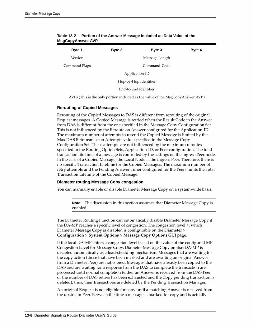
Table 13-2 Portion of the Answer Message Included as Data Value of theMsgCopyAnswer AVP
Byte 1 Byte 2 Byte 3 Byte 4
Version Message Length
Command Flags Command-Code
Application-ID
Hop-by-Hop Identifier
End-to-End Identifier
AVPs (This is the only portion included as the value of the MsgCopyAnswer AVP.)
Rerouting of Copied Messages
Rerouting of the Copied Messages to DAS is different from rerouting of the originalRequest messages. A Copied Message is retried when the Result Code in the Answerfrom DAS is different from the one specified in the Message Copy Configuration Set.This is not influenced by the Reroute on Answer configured for the Application-ID.The maximum number of attempts to resend the Copied Message is limited by theMax DAS Retransmission Attempts value specified in the Message CopyConfiguration Set. These attempts are not influenced by the maximum reroutesspecified in the Routing Option Sets, Application-ID, or Peer configuration. The totaltransaction life time of a message is controlled by the settings on the ingress Peer node.In the case of a Copied Message, the Local Node is the ingress Peer. Therefore, there isno specific Transaction Lifetime for the Copied Messages. The maximum number ofretry attempts and the Pending Answer Timer configured for the Peers limits the TotalTransaction Lifetime of the Copied Message.
Diameter routing Message Copy congestion
You can manually enable or disable Diameter Message Copy on a system-wide basis.
Note: The discussion in this section assumes that Diameter Message Copy isenabled.
The Diameter Routing Function can automatically disable Diameter Message Copy ifthe DA-MP reaches a specific level of congestion. The congestion level at whichDiameter Message Copy is disabled is configurable on the Diameter >Configuration > System Options > Message Copy Options GUI page.
If the local DA-MP enters a congestion level based on the value of the configured MPCongestion Level for Message Copy, Diameter Message Copy on that DA-MP isdisabled automatically as a load-shedding mechanism. Messages that are waiting forthe copy action (those that have been marked and are awaiting an original Answerfrom a Diameter Peer) are not copied. Messages that have already been copied to theDAS and are waiting for a response from the DAS to complete the transaction areprocessed until normal completion (either an Answer is received from the DAS Peer,or the number of DAS retries has been exhausted and the Copy pending transaction isdeleted); thus, their transactions are deleted by the Pending Transaction Manager.
An original Request is not eligible for copy until a matching Answer is received fromthe upstream Peer. Between the time a message is marked for copy and is actually
Diameter Message Copy
13-6 Diameter Signaling Router Diameter User's Guide

copied, the local DA-MP's status can change. Therefore, Diameter Message Copy isdeclared as disabled when the next Answered marked message is processed by thePending Transaction Manager to have a copy made and the local DA-MP hascongested (based on the Message Copy MP Congestion Level). A Message Copy alarmis raised at this time.
Diameter Message Copy is enabled again when the local DA-MP Congestion Levelabates (based on the configured Message Copy MP Congestion Level), and an attemptis made to copy a message that is marked for copy. The Message Copy disabled alarmis cleared only when the local DA-MP congestion (Message Copy) is abated below theconfigured Message Copy MP Congestion Level, and a message marked for copy isprocessed by Diameter Message Copy.
If Diameter Message Copy processing capacity reaches 100% congestion, furtherMessage Copy actions cannot be completed. To process the messages, DiameterMessage Copy is not disabled; but an alarm is raised to indicate the processingcapacity status until the congestion abates.
Message Copy Configuration Sets
A Message Copy Configuration Set (MCCS) is a collection of attributes thatdetermine the messages to be copied (Request or optionally the Answer), the Resultcode/Experimental Result code on which the Message Copy is initiated, and thenumber of retries to be made if the Message Copy attempt to the DAS fails. A MessageCopy Trigger Point must specify a Message Copy Configuration Set when the messageis marked for copying.
Up to 100 Message Copy Configuration Sets are supported. The following elementscan be configured for each Message Copy Configuration Set; the fields are described in Message Copy Configuration Set elements:
Message Copy Configuration Set NameEach Message Copy Configuration Set is assigned a unique name. A default MessageCopy Configuration Set named Default is always provided and can be edited, but notdeleted.
Route List of the DAS NodeThe required Route List of the DAS Node element of the MCCS specifies the RouteList to use for copying the message. This Route List consists of a Peer Route Group orConnection Route Group. The DAS Peers are treated like any other Diameter Peerswith respect to Connection establishment and management. The CEx messages areexchanged upon establishing a Connection, and the DWx/DPx messages areexchanged as needed. Requests matching the advertised Application-ID inly arecopied to the DAS. If a message has been marked for Message Copy to a certain DASRoute List and all the available Connections to the Peers in the Route List do notsupport the Application-ID present in the copied message, the copy is not performed,an Event is raised, and the copy action is ignored.The Route List must exist before the MCCS can select it. Route Groups must beconfigured before Route Lists can be configured in Diameter Configuration.
The DASs are expected to be direct Peers. Message Copy is not supported to DASsconnected through other diameter applications, relays, and proxy servers.
Message Copy Request TypeThe original Request significantly altered as it traverses the routing network.Depending on the function provided by the DAS, the DAS might be interested inseeing the Request before or after the modifications made. The DAS can receive acopy of the Original Ingress Request or the Original Egress Request. The Original
Diameter Message Copy
Diameter Message Copy 13-7

Ingress Request is the Request as received before any manipulation. The OriginalEgress Request is the Request as sent to the upstream Peer. The default is OriginalIngress Request.
Ingress Answer IncludedIn some cases, DAS must query the contents of the original Answer received for theRequest message in order to accomplish the function. When the Ingress AnswerIncluded element is set to YES, Diameter Message Copy copies the ingress Answerthat is received for the original Request Message to the DAS, as described in IngressAnswer Message Encoding. The default is NO, Answer not included.
Original Answer Result Code for Message CopyThe Result Code of the Answer messages corresponding to the Original Requestsmight influence the Message Copy action. For example, a DAS might not be interestedin receiving a copy of the Request if the Original Transaction ended with an Answerthat contained a non-2xxx Result Code/Experimental Result Code. The DAS canreceive a copy of the message based on the outcome of the Original Transaction. If2xxx is selected, Diameter Message Copy is performed only if the value of the ResultCode/Experimental Result Code AVP in the Original Answer is a 2xxx. If Any ResultCode is selected, the Message Copy is performed regardless of the Result Code/Experimental Result Code AVP value as long as the diameter routing functionreceives an Answer from the upstream Peer. The default is to copy on 2xxx only.The Diameter Message Copy is not performed if the Answer is generated or if theoriginal Request times out.
Alternate routing is not attempted on a given Request, but in such cases the DiameterMessage Copy is attempted just once regardless of the number of alternate routingattempts. Message Copy is evaluated based on the value of the Result Code/Experimental Result Code AVP in the Original terminating Answer.
DAS Answer Result CodeDASs are expected to respond with a 2xxx Result Code or an error Result Code/Experimental Result Code upon the receipt of the copied message. If an appropriateAnswer is not received, the copied message is transmitted again for the configuredmaximum number of times until the appropriate response is received. The DASMessage Copy Answer Result Code can be configured with one of the followingchoices:
• 2xxx Result Code/Experimental Result Code in the DAS Answer
• Any Result Code/Experimental Result Code in the DAS Answer
Max DAS Retransmission AttemptsThis value determines the maximum number of times a copied message is transmittedagain using the specified Route List, until the DAS Answer containing the specifiedResult Code is received.In the event that an appropriate Answer is not received, the copied message istransmitted again for the configured number of times until the appropriate responseis received. The default is 0 and the range is 0-4. If the value is 0, there are noretransmission attempts.
Diameter Configuration for Message Copy
The following Diameter Configuration components must be configured if DiameterMessage Copy is used in the system:
• For PRT-Triggered Message Copy:
Diameter Message Copy
13-8 Diameter Signaling Router Diameter User's Guide

– One or more Route Groups
– One or more Route Lists
– One or more Message Copy Configuration Sets
– One or more Peer Route Tables
– One or more Peer Routing Rules
A Message Copy Configuration Set must be specified in each Peer RoutingRule that is used to trigger Message Copy.
– Set the Message Copy Feature element to Enabled in Diameter >Configuration > System Options
• For Mediation-Triggered Message Copy:
– One or more Route Groups
– One or more Route Lists
– One or more Message Copy Configuration Sets
A Message Copy Configuration Set must be specified in each Rule TemplateAction that is used to trigger Message Copy for Mediation.
– Set the Message Copy Feature element to Enabled in Diameter >Configuration > System Options
PRT-Triggered Message Copy
A Peer Routing Rule can be configured such that Request messages routed throughthat Peer Routing Rule can be marked for copying to a Diameter Application Server(DAS). Diameter Message Copy uses the contents and conditions that are specified in aMessage Copy Configuration Set (MCCS) for copying the message. If there is validMCCS configured in the Peer Routing Rule, the Diameter Routing Function marks themessage for copy and attaches the specified MCCS. Diameter Message Copy validatesthe transaction using the MCCS and copies the message to the DAS.
Mediation-Triggered Diameter Message Copy
The Mediation Rule Template Message Copy Action can be defined to triggerDiameter Message Copy for messages that are processed by Diameter Mediation.Mediation Rule Templates are described in the Diameter Mediation User's Guide andassociated online help.
The Message Copy Action triggers Diameter Message Copy, and specifies theDiameter-configured Message Copy Configuration Set (MCCS) that contains theRequest/Answer content criteria to be used by Diameter Message Copy to copy themessage to a DAS. The Message Copy Configuration Set specifies a configured RouteList for the DAS. See Message Copy Configuration Sets.
Mediation Message Copy can be performed only for Request messages; the MessageCopy Action is ignored if set at Mediation Trigger Point ATP10 (Diameter Answermessage before being forwarded to connection).
If Diameter Message Copy is triggered for the same message from multiple locations,the Message Copy Configuration Set for the latest Message Copy triggering is used.
Diameter Message Copy
Diameter Message Copy 13-9

In the case of Request re-route due to invalid Result code, only the Message CopyConfiguration Set that is associated with the Answer that completes the transaction atATP1 is considered.
The Message Copy is performed after the completion of the original transaction. TheCopied Message is not processed by the Mediation Triggering Points.
Diameter Message Copy
13-10 Diameter Signaling Router Diameter User's Guide

14Diameter Capacity and Congestion Controls
The diameter routing function provides the features and functions for per-connectionand per-MP capacity and congestion control. Egress Throttle Groups can monitorEgress Message Rate and Pending Transactions across multiple DA-MPs.
Introduction
Note: RADIUS design dictates that most of the per-connection and per-MPfeatures apply in a similar way to both RADIUS and Diameter connections.
The diameter routing function provides the following features and functions forcapacity and congestion control:
• DA-MP Overload Control
• Per-Connection Ingress MPS Control
• User Configurable Message Priority (not supported for RADIUS)
• Remote BUSY Congestion (not supported for RADIUS)
• Egress Transport Congestion
• Per-Connection Egress Message Throttling
• User-Configurable Connection Pending Transaction Limiting
• Egress Throttle Groups
• Functions associated with Message Priority and Connection Congestion:
– Egress Request routing incorporates Request Message Priority andConnection Congestion Level in its Connection selection criteria.
– The Routing Option Set associated with the ingress Request specifies whataction is taken by diameter when routing of a Request is abandoned and thelast Connection evaluated was congested.
– The maintenance status for a congested Connection indicates whether thecongestion is due to Remote BUSY Congestion (not supported for RADIUS),Egress Transport Congestion (not supported for RADIUS), or Egress MessageThrottling.
The Diameter Transport Function services its per-Connection ingress sockets with per-Connection MPS controls that ensure fairness in reading ingress messages for allestablished Connections.
Diameter Capacity and Congestion Controls 14-1

The Diameter Transport Function services its per-Connection egress queues withcontrols that ensure fairness in forwarding egress messages to Peers for all establishedConnections.
Egress Throttle Groups monitor Egress Message Rate, Pending Transactions, or both,for logical groups of Diameter/RADIUS Connections or Peers, or both, across multipleDA-MPs on a Network Element.
DA-MP Overload ControlDA-MP Overload Control (Message Priority and Color-Based DA-MP OverloadControl) provides a mechanism for managing internal/local DA-MP congestiondetection and control.
The DA-MP Overload Control feature tracks ingress message rate, calculates theamount of traffic that needs to be shed based on CPU congestion, and sheds that trafficbased on Message Priority, Message Color, and discard policy.
Message Color is used as a means for differentiating Diameter Connections that areunder-utilized versus those that are over-utilized with respect to ingress traffic - trafficfrom under-utilized Connections is marked green by the Per-Connection Ingress MPSControl (PCIMC) feature, while traffic from over-utilized Connections is markedyellow.
The following DA-MP Congestion Controls are associated with reducing the trafficprocessing load on the DA-MP when congestion is detected:
• Internal Resource Monitoring and Control
The availability of key traffic-sensitive internal software resources (stack queuesand buffer pools) is monitored in real-time against their static maximum capacity.
When resource availability drops below engineered thresholds, alarms aregenerated. When resource availability is exhausted, controls are invoked toprevent over-utilization. Resource utilization KPIs and measurements providereal-time and long-term information for making decisions about system capacityand growth.
• DA-MP Overload Control
Traffic loads, if allowed to exceed the DA-MP's engineered capacity, degrade theeffective performance of the DA-MP, increase message latency, and can result inmessage loss. DA-MP Overload Control is responsible for reducing the trafficprocessing load to insure that the MP meets its performance specifications. MPProcessing Overload Control monitors the Diameter Process CPU utilization ofthe Diameter Process.
Limitations
• DA-MP Overload Control is limited to local MP congestion management and doesnot address remote Diameter node congestion management.
• Automatic recovery from persistent MP or egress Connection congestion is notsupported. Manual intervention is required.
Diameter Configuration for DA-MP Overload Control
The following Diameter Configuration components are used for DA-MP OverloadControl:
• MP Profiles
DA-MP Overload Control
14-2 Diameter Signaling Router Diameter User's Guide

A DA-MP Profile is assigned to each DA-MP in the system. See the MP Profilesinformation in Diameter Common User's Guide.
The assigned DA-MP Profile indicates the Engineered Maximum MPS for the DA-MP and the Message Rate Alarm Set and Clear Thresholds. These engineering-configured MP Profiles values shown on the MPs menu vary depending on thetype of server used for the DA-MP.
The following elements can be user-configured from the Diameter Common >MPs menu for use by the DA-MP Overload Control feature:
– Congestion Level 1 Discard Percentage - The percent below the DA-MPEngineered Ingress MPS that DA-MP Overload Control polices the total DA-MP ingress MPS to when the DA-MP is in Congestion Level 1.
– Congestion Level 2 Discard Percentage - The percent below the DA-MPEngineered Ingress MPS that DA-MP Overload Control polices the total DA-MP ingress MPS to when the DA-MP is in Congestion Level 2.
– Congestion Level 3 Discard Percentage - The percent below the DA-MPEngineered Ingress MPS that DA-MP Overload Control polices the total DA-MP ingress MPS to when the DA-MP is in Congestion Level 3.
– Congestion Discard Policy - The order of Message Priority and Color-basedtraffic segments to consider when determining discard candidates for theapplication of treatment during DA-MP Congestion processing. Thefollowing order is considered: Color within Priority, Priority within Color,and Priority Only.
– Danger of Congestion Discard Percentage - The percent of total DA-MPingress MPS above the DA-MP Engineered Ingress MPS that DA-MPOverload Control discards when the DA-MP is in danger of congestion.
• Routing Option Sets
A Routing Option Set is a set of user-configurable routing options assigned to aningress Diameter transaction. A Routing Option Set can be assigned to Peer Nodesand Diameter Application IDs.
DA-MP Overload Control uses the following options:
– Resource Exhausted Action
– Resource Exhausted Result-Code Value
– Resource Exhausted Vendor-ID Value
– Resource Exhausted Error-Message Value
Per-Connection Ingress MPS ControlThe Per-Connection Ingress MPS Control (PCIMC) feature limits to a configurablelevel the per-connection ingress message rate of each connection. Correctly configuredmessage rate controls ensure that a single connection cannot use the majority of theresources. (No limiting is done by PCIMC for the egress message rate).
The PCIMC feature:
• Is always available in the system.
Per-Connection Ingress MPS Control
Diameter Capacity and Congestion Controls 14-3

• Is applied in the diameter transport function, which is used by all diameterapplications.
Capacity management for this feature can be logically separated into:
• Management of the ability of the MP server to process ingress diameter messages- how the MP server's resources are distributed to configured connections.
• Management of the ability of a given connection to process ingress diametermessages - how each connection behaves given its configured reserved andmaximum ingress MPS settings.
Per-Connection Capacity Management
Per-connection ingress MPS control allocates a DA-MP's ingress message processingcapacity among the diameter peer connections that it hosts. Each peer connection isallocated, through user-configuration, a reserved ingress MPS message processingcapacity and a maximum ingress MPS message processing capacity.
The reserved capacity for a connection is available for exclusive use by the connection.The capacity between a connection's reserved and maximum capacity is shared withother connections hosted by the DA-MP.
Per-Connection Ingress Message Coloring
In addition to enforcing ingress message rate limits on a per-connection basis, PCIMCcolors ingress messages based on the reserved and average ingress message rates.message color can be used at other traffic shedding points, such as DA-MP OverloadControl.
Traffic from under-utilized connections is marked green by per-connection ingressmessage controls, while traffic from over-utilized connections is marked yellow. Trafficdiscarded by PCIMC due to capacity exhaustion (per-connection or shared) is markedred and is not considered for any subsequent processing.
The following items describe the numbered items in Figure 14-1:
• When the connection's average ingress MPS rate is equal to or below itsconfigured reserved ingress MPS, all messages processed by the connection arecolored green.
• When the connection's average ingress MPS rate is above its configured reservedingress MPS, all messages up to reserved ingress MPS are colored green andabove that are colored green.
• When the connection's ingress MPS rate is above its configured maximum ingressMPS, the messages in excess of maximum ingress MPS are dropped, unless NGN-PS feature is enabled.
• When NGN-PS feature is enabled, then messages in excess of maximum ingressMPS are dropped, except NGN-PS messages.
Note: If the connection's reserved ingress MPS is 0, all the messagesprocessed by the connection are colored yellow.
Per-Connection Ingress MPS Control
14-4 Diameter Signaling Router Diameter User's Guide

Figure 14-1 Per-Connection Message Coloring
Message Discard Policy
The Message Discard Policy function considers the priority of the message whilediscarding the message.
Each peer connection tracks the priority of the ingress message and discards themessages that exceed the maximum ingress MPS configured for the connection.
The request messages are discarded based on the configured resource exhausted actionthat is set as abandon the request with no answer or send answer. For a description ofResource Exhausted Action see Diameter Routing Option Sets.
Per MP Server Capacity Management
MPS rates and thresholds are used to manage ingress message MPS as it relates to theMP server as a whole.
A DA-MP has two configured ingress message rate capacity limits:
• Engineered Ingress MPS is the maximum ingress message rate that a DA-MPsupports without overload.
This value provides a limit to the total reserved ingress MPS of all diameterconnections assigned to the DA-MP. The value is displayed for the MP Profileassigned to the DA-MP.
• MP Engineered Maximum Ingress MPS is a configurable ingress MPS limit thatdictates the maximum rate at which the DA-MP attempts to process messagesfrom all diameter connections.
This value may be greater than the MP engineered ingress MPS.
The DA MP monitors its MPS rate and limits the rate to an MP engineered ingressMPS value. If the MP engineered ingress MPS rate is exceeded, overload can occur and
Per-Connection Ingress MPS Control
Diameter Capacity and Congestion Controls 14-5

ingress messages can be discarded (due to MP ingress MPS limiting and MPcongestion controls).
Diameter Configuration for Per-Connection Ingress MPS Control
Each diameter connection is associated with a capacity configuration set that includesthe following configurable elements:
• Reserved Ingress MPS defines the capacity reserved exclusively for the connectionand not available for use by other connections.
The reserved ingress MPS cannot exceed the configured maximum ingress MPSfor a given connection. A connection can be configured with a zero reservedingress MPS value; such connections do not reserve message processing capacity.
The reserved ingress MPS for a connection cannot be used by any otherconnection, regardless of the load offered to other connections.
If the reserved ingress MPS capacity is set to a non-zero value, that value times thenumber of connections using that capacity configuration set on a given MP servermust not be allowed to exceed the MP maximum reserved ingress MPS (which isequal to the MP engineered ingress MPS - the highest MPS rate at which the MPserver can process ingress diameter messages).
• Maximum Ingress MPS defines the maximum rate in ingress diameter messagesper second that the connection is allowed to process.
The maximum Ingress MPS must be greater than or equal to the reserved ingressMPS. Any difference between the maximum ingress MPS and the reserved ingressMPS represents MP server resources that are shared among connections that areusing the same capacity configuration set.
The configured maximum ingress MPS of a connection cannot exceed theengineered ingress MPS of the connection (the ingress MPS that a connection canprocess at a sustained rate without errors). If the connection has reserved ingressMPS, the configured maximum ingress MPS must be greater than or equal to thereserved ingress MPS. All connections must have a non-zero configuredmaximum ingress MPS; otherwise they would not be allowed to process traffic atall. (The maximum ingress MPS value in the default capacity configuration set isnon-zero.)
The sum of the maximum ingress MPS configured for all connections on a MPserver can exceed the MP engineered ingress MPS to the highest MPS rate atwhich the MP server can process ingress diameter messages.
• Ingress MPS Minor Alarm Threshold defines the percent of the connection'smaximum ingress MPS at which a minor alarm is triggered.
The ingress MPS minor alarm threshold value must be less than the ingress MPSmajor alarm threshold value
• Ingress MPS Major Alarm Threshold defines the percent of the connection'smaximum ingress MPS at which a majoralarm is triggered.
The ingress MPS major alarm threshold must be greater than the ingress MPSminor alarm threshold.
• Ingress MPS Alarm Abatement Time defines the minimum time that aconnection's ingress message rate must remain less than or equal to the respectiveAbatement threshold before the alarm clears or its severity reduced from major tominor.
Per-Connection Ingress MPS Control
14-6 Diameter Signaling Router Diameter User's Guide

• Convergence Time - Defines the time it takes in milliseconds to converge to a persecond rate that is used to calculate the ingress MPS of the connection.
A default capacity configuration set is provided; additional capacity configuration setscan be configured. The default capacity configuration set is used for a connection if noother capacity configuration set is assigned to the connection. The elements of thedefault capacity configuration set have the following default values:
• Reserved Ingress MPS - Zero MPS
• Maximum Ingress MPS - Value equal to the engineered ingress MPS for theconnection
• Ingress MPS Minor Alarm Threshold - 50% of the configured maximum ingressMPS
• Ingress MPS Major Alarm Threshold - 80% of the configured maximum ingressMPS
• Ingress MPS Alarm Abatement Time - 2000ms
• Convergence Time - 1000ms
Maintenance and Monitoring for Per-Connection Ingress MPS Control
The PCIMC feature provides the following maintenance and monitoring information:
• Alarms and measurements to assist the network operator to detect and avoidpossible capacity issues related to messaging rates
• The ability to view the average ingress diameter MPS for each connection
The PCIMC feature uses the following GUI information:
• Diameter > Configuration > Connections specifies which capacity configurationset the connection uses.
• The Diameter > Configuration > Configuration Sets > Capacity ConfigurationSets pages provide elements for configuring capacity configuration sets.
• Diameter > Maintenance > Connections reports KPI 10500 for average ingressMPS for each diameter connection (ingress messages per second).
For each connection, the MP server maintains the average number of ingressdiameter messages per second read from the socket. This is the rate at whichingress diameter messages are read from the socket, not the rate at which ingressdiameter messages arrive at the socket. There is no efficient means to know therate at which messages actually arrive.
Connection Alarm
The PCIMC feature provides a connection alarm with two severities to alert thenetwork operator when the average ingress MPS rate goes above the configuredthresholds for percentage of the configured maximum ingress MPS for the connection.
The connection ingress MPS alarm is a per-connection alarm that can be configured ina connection's capacity configuration set to trigger at a minor and major capacitythreshold.
The minor alarm is asserted when the MPS rate exceeds the configured ingress MPSminor alarm threshold value for the connection. The minor alarm is cleared when the
Per-Connection Ingress MPS Control
Diameter Capacity and Congestion Controls 14-7

MPS rate falls 5% below the ingress MPS minor alarm threshold value configured forthe connection.
The major alarm is asserted when the MPS rate exceeds the ingress MPS major alarmthreshold value configured for the connection. The major alarm is converted to aminor alarm when the MPS rate falls 5% below the ingress MPS major alarm thresholdvalue configured for the connection.
An alarm cannot be abated until an abatement time delay has expired. For example, ifa minor alarm is asserted, the alarm cannot be cleared until the abatement time delayhas expired and the average ingress MPS for the connection is 5% below the minoralarm assert percentage.
The alarm abatement time delay affects only clearing of alarms, not asserting ofalarms. Therefore, it is possible to transition rapidly from a minor alarm to a majoralarm.
Remote Congestion Controls
Note: Remote Busy congestion and egress transport congestion are notsupported for RADIUS.
The following features provide remote congestion controls:
Remote BUSY CongestionAddresses Remote Congestion detectionThe Remote BUSY Congestion feature calls for the server to send aDIAMETER_TOO_BUSY Answer, which is can be used by the clients to stop sendingtraffic for some duration. The feature addresses Remote Congestion detection and thesteps to be taken to alleviate the situation.
Egress Transport CongestionSupports use of transport congestion statusThe Egress Transport Congestion feature uses Congestion Levels to manage the egressmessage traffic flow on a Diameter Peer Connection when the Connection's TCP/SCTP send buffer is exhausted, as indicated by the TCP/SCTP socket being blocked.The socket is blocked when the Diameter Transport Function attempts to write newdata to the TCP/SCTP socket fail due to insufficient send buffer space. When aDiameter Connection socket becomes blocked, the Diameter Transport Function setsthe Egress Transport Congestion Level to CL-98 and discards any received Request orAnswer messages.
Per-Connection Egress Message ThrottlingTargets congestion avoidanceThe Per Connection Egress Message Throttling feature targets congestion avoidanceby throttling the volume of Diameter traffic being sent over a Connection when thetraffic exceeds the configured maximum egress message rate of the Connection.
User-Configurable Connection Pending Transaction LimitingProvides a pending transaction limit for each Peer ConnectionUser-Configurable Connection Pending Transaction Limiting (UC-CPTL) provides aconfigurable pending transaction limit for each Peer Connection, to customize thedistribution of the available Pending Transaction Records on a DA-MP based on thevarying deployment requirements. The limit can be configured independently foreach DA-MP.
Remote Congestion Controls
14-8 Diameter Signaling Router Diameter User's Guide

Routing Based on Congestion Level
Features such as Remote BUSY Congestion, Egress Transport Congestion, and PerConnection Egress Throttling Control are used to control the flow of egress traffic bysetting a feature-specific Congestion Level for a Diameter Connection. CertainRequests can be prioritized over others, using the User Configurable Message Priorityfeature.
The Connection Priority Level (CPL) is an overall Congestion Level for the Connectionthat is based upon the highest Congestion Level of the various egress traffic controlfeatures. The CPL is used by the Diameter Routing Function when making egressmessage routing decisions based on the Priority provided by the User ConfigurableMessage Priority feature. No message can be forwarded to a Diameter Connection thathas a Priority level less than the CPL for that Connection
Up to five Congestion Levels (CL-0, CL-1, CL-2, CL-3, and CL-98) are supported, withCL-0 indicating no congestion to CL-98 indicating that the Connection is blocked. Theintermediate Congestion Levels CL-1, CL-2, and CL-3 indicate the increasing severityof congestion.
Each feature has a Congestion Level range, as follows:
• Remote BUSY Congestion Levels: CL-0. CL-1, CL-2, and CL-3
• Egress Transport Congestion Levels: CL-0. CL-1, CL-2, CL-3, and CL-98
• Per Connection Egress Message Throttling Congestion Levels: CL-0. CL-1, CL-2,and CL-3
The CPL value for a Connection (CONN-CPL) is based on the maximum CongestionLevel of the features.
Egress Request routing and Answer forwarding functions use the ConnectionCongestion Level in conjunction with the Message Priority to determine how Requestsand Answers must be handled over an egress Connection. Message Priority andConnection Congestion Level in the Connection selection criteria are used to avoidsending messages of Priority x and lower to Connections currently at CongestionLevel x+1.
All Answers are assigned a Message Priority of 3, while Requests can be assignedMessage Priorities 0 through 2. Messages with a Priority greater than or equal to theCongestion Level are allowed, while messages with lower Priorities are not deliveredon this Connection. This arrangement ensures that Answers have the highest Priorityand are always routed unless a Connection becomes blocked, and depending upon thelevel of congestion some or all of the Requests may be allowed. Table 14-1 summarizesthis behavior.
Table 14-1 CLs, CPLs, and Message Treatment
Connection CPLValue
Message PrioritiesAllowed
Message PrioritiesNot Allowed Comment
98 None All Requests nor Answers can besent on the Connection
3 3 0, 1, 2 Allow only Answers to besent on the Connection
Remote Congestion Controls
Diameter Capacity and Congestion Controls 14-9

Table 14-1 (Cont.) CLs, CPLs, and Message Treatment
Connection CPLValue
Message PrioritiesAllowed
Message PrioritiesNot Allowed Comment
2 3, 2 0, 1 Allow only Answers andPri=2 Requests to be sent onthe Connection
1 3, 2, 1 0 Allow only Answers andPri=2,1 Requests to be senton the Connection
0 All None All Requests and Answerscan be sent on theConnection
Congestion Levels can be set by multiple features. For example, a particularConnection may have received a DIAMETER_TOO_BUSY for a Priority 1 Request(resulting in CL-2 congestion), and while abating may have experienced transportcongestion (CL-98). Therefore, the concept of Connection Priority Level (CPL) is usedto consider the Congestion Levels reported by all the features while making routingdecisions.
The CPL value is a function of Operational Status and the Congestion Levels reportedby the Remote BUSY Congestion, Egress Transport Congestion, and Per ConnectionEgress Message Throttling features. Table 14-2 summarizes this behavior.
• The CPL Value for a Connection is based on the worst-case (highest) value:
CPL Value of a Connection = Max (X1, X2, X3, X98)
• This composite CPL value is then used by the Diameter Routing Function asshown in Table 14-1.
Table 14-2 Mapping Congestion Levels to CPL Values
Attribute Value CPL Value
X1: Diameter Connection Operational Status Available
Degraded
Unavailable
0
1 - 3, 98
99
X2: Diameter Connection Remote BUSYCongestion
CL-0 through CL-3 0-3
X3: Diameter Connection Egress TransportCongestion
CL-0, CL-1, CL-2, CL-3,and CL-98
0, 1, 2, 3, and98
X98: Diameter Connection Egress MessageThrottling
CL-0 through CL -3 0 - 3
Capacity and Ranges
Table 14-3 specifies the capacity and ranges for Remote BUSY and Egress MessageRate.
Remote Congestion Controls
14-10 Diameter Signaling Router Diameter User's Guide

Table 14-3 Remote BUSY and EMR Capacity Ranges
Item Maximum Description
Remote BUSY processing 1000 Remote BUSY processing on up to 1000simultaneous Diameter connections on a singleDA-MP
Remote BUSY processing 2000 Remote BUSY processing on up to 2000simultaneous Diameter connections on a singleDA-MP
Remote BUSY processing 1000 Remote BUSY processing on up to 16000simultaneous Diameter connections on a singleDA-MP
Egress TransportCongestion processing
1000 Egress Transport Congestion processing on up to1000 simultaneous Diameter connections on asingle DA-MP
Egress TransportCongestion processing
2000 Egress Transport Congestion processing on up to2000 simultaneous Diameter connections on asingle DA-MP
Egress TransportCongestion processing
1000 Egress Transport Congestion processing on up to16000 simultaneous Diameter connections on asingle DA-MP
Egress MessageThrottling
500 Egress Message Throttling on up to 500simultaneous Diameter connections on a singleDA-MP
Egress MessageThrottling
500 Egress Message Throttling on up to 500simultaneous Diameter connections on a single DA
Egress MessageThrottling
500 Egress Message Throttling on up to 500simultaneous Diameter connections on a single DA
Egress MessageThrottling ConfigurationSets
50 Up to 50
User Configurable Message Priority
Note: User Configurable Message Priority is not supported for RADIUS.
User Configurable Message Priority provides the following functions to set thePriority of messages that are handled and to use that Priority to as input into decisionsfor load shedding, message throttling, and egress Connection selection:
• A method to assign Message Priorities to incoming Diameter Requests.
The Priorities assigned are based on the combination of Application-ID andCommand-Code, and the Connection upon which the Request arrives. Acombination of Application-ID, Command-Code, and associated Priority is calleda Message Priority Rule.
Remote Congestion Controls
Diameter Capacity and Congestion Controls 14-11

• Association of a Message Priority Configuration Set with a Connection.
• Association of a Message Priority Configuration Set with a Peer Node.
• Definition of a Message Priority in a Peer Routing Rule.
• A method for Request messages arriving that are to be marked with a MessagePriority.
• A method for the Message Priority determined by the first diameter signalingrouter to handle a Request to be communicated to any other diameter signalingrouter that also handles the Request.
Message Priority is determined based in part on the Connection on which theRequest arrives at the first diameter signaling router to handle the Request. Asecond diameter signaling router to handle the Request is not able to establish thePriority based on the original ingress Connection.
• A method for exception routing and load shedding that allows the Remote BUSYCongestion feature to use the Message Priority when determining which messagesare exception-routed or shed.
• A method for exception routing and load shedding that allows the EgressTransport Congestion feature to use the Message Priority when determiningwhich messages are exception-routed or shed.
• A method for the message throttling that allows the Per Connection EgressMessage Throttling feature to use the Message Priority when determining whichmessage are exception routed or shed.
Request messages can be assigned a Message Priority value of 0, 1, or 2 (lowest tohighest Priority).
Answer messages are always assigned a Message Priority value of 3 (the highestPriority).
Messages that are given a higher Priority have a lower probability of being dropped aspart of shedding or throttling logic, but having a higher Priority does not imply thatthe message is routed before a message with a lower Priority. Having a higher Prioritydoes not guarantee that a messages is never dropped as a result of shedding ofmessages due to congestion or resource exhaustion. The arrival pattern of the Requestshas an impact on which messages are shed.
Message Priority can be assigned to ingress messages upon entrance based on thefollowing:
• The Connection on which a message arrives
• The Peer Node from which a message is sent
• A Peer Routing Rule
A configured Message Priority Configuration Set can be assigned to a Connection or toa Peer Node
A Message Priority Configuration Set is configured with one or more Message PriorityRules that specify Application IDs, Command Codes, and the Message Priority that isassigned to Request messages that enter on a Connection that has been assigned theMessage Priority Configuration Set.
Remote Congestion Controls
14-12 Diameter Signaling Router Diameter User's Guide

Message Priority is assigned to ingress Request messages based on message contentusing the strongest matching entry in the Configuration Set:
• Application-ID + Command-Code combination
• Application-ID
• All Request messages (Application ID and Command Code values are *)
In a network where Diameter messages traverse multiple diameter routes, RequestMessage Priority might need to be assigned on one diameter signaling router and usedby any and all diameter signaling routers in the routing path.
Diameter embeds Priority in all Requests that it handles. The method used forembedding Priority in egress Requests is transparent to non-Diameter nodes.
Egress Request routing and Answer forwarding use Message Priority and ConnectionCongestion Level in its Connection selection criteria to avoid sending Priority xmessages to Connections currently at Congestion-Level x+1.
Diameter Configuration for User Configurable Message Priority
The User Configurable Message Priority feature provides the ability to define MessagePriority Configuration Sets (MPCS). Each MPCS contains the following information:
• MPCS Name - The Name is used when associating the Configuration Set with aConnection or Peer Node
• Message Priority Rules - Sets of Application-ID, Command-Code, and Priority
– Application-ID - The Diameter Application-ID. The Application-ID can be anasterisk (*) indicating that all Application-IDs match this Message PriorityRule
– Command-Code - The Diameter Command-Code. The Command-Code canbe an asterisk (*) indicating that all Command-Codes within the specifiedapplication match this Message Priority Rule
If multiple Command-Codes with the same Application-ID are to get thesame Message Priority, then there must be a separate Message Priority Rulecombination for each Command-Code.
– Priority - The Priority applied to all Request messages that match theApplication-ID and Command-Code combination
The Application ID and Command Code must be configured in DiameterConfiguration before they can be used to configure a Message Priority Rule.
A Default Message Priority Configuration Set is provided that contains one MessagePriority Rule; the Message Priority Rule is set to accept all Application IDs and allCommand Codes (values are *) and has Message Priority set to 0 . The DefaultMessage Priority Configuration Set can be assigned and used if no other MessagePriority Configuration Set is assigned to the Connection or the Peer Node (it can beedited if needed).
A total of 20 Message Priority Configuration Sets can be configured per NE. EachMessage Priority Configuration Set supports up to 50 Message Priority Rules.
A Connection or Peer can be configured with either a MPCS or to get Message Priorityfrom the ingress Request. If it is configured to get Message Priority from the ingressRequest, then it is not possible to configure a MPCS for the Connection or Peer.
Remote Congestion Controls
Diameter Capacity and Congestion Controls 14-13

In Peer Routing Rules, Message Priority valid values are No Change, 0, 1 and 2. 0 isthe lowest priority. The Message Priority value is applied to the message only whenthe Peer Routing Rule Action value is set to Route to Peer.
The following Message Priority treatment configuration options can be selected:
• None (default)
• Apply a MPCS (by selecting from a list of configured MPCSs)
• Read from message - Used to indicate that the Priority should be taken from theingress message. This is used for router-to- router Connections as a way ofconveying Message Priority
This option does not apply to Peer Routing Rules, which have the options None(default) and Apply an MPCS.
Table 14-4 indicates which method is used. If the Request does not match a rule in theselected Message Priority Configuration Set, then the Request is assigned a Priorityvalue of zero (0).
Table 14-4 Message Priority Treatment Methods
Message PriorityConfiguration SetConnection Setting
Message PriorityConfiguration Set PeerNode (for Connection)Setting
How Priority is Set forIngress Requests onConnection
Not Set Not Set Use NE
Not Set MPCS X Use MPCS X to assignPriority to Ingress Requests
Not Set Get Priority from IngressRequests
Extract Priority from IngressRequests
MPCS Y (Don't Care) Use MPCS Y to assignPriority to Ingress Requests
Get Priority from IngressRequests
(Don't Care) Extract Priority from IngressRequests
Remote BUSY Congestion
Note: Remote BUSY Congestion is not supported for RADIUS.
The Remote BUSY Congestion feature can be used per Connection to reduce theamount of message traffic sent to a Diameter Connection when an adjacent DiameterPeer Node is unable to process messages as fast as they are sent to it on theConnection.
Note: The User Configured Message Priority feature is a prerequisite for theRemote BUSY Congestion feature.
A Connection is considered congested or BUSY if the following conditions exist:
Remote Congestion Controls
14-14 Diameter Signaling Router Diameter User's Guide

• An Answer message containing Diameter_TOO_BUSY Result Code is received onthe Connection
• The Answer message was originated by the Peer Node (the Origin-Host of theAnswer message is the same as the Connections Peer FQDN.
The status is set to BUSY only for the Connection of a Peer on which DIAMETER TOOBUSY is received. The other Connections between the diameter signaling router andthe Peer might or might not be BUSY.
Remote BUSY Congestion applies only to adjacent nodes. If the node which initiatedthe DIAMETER_TOO_BUSY, as determined by the Origin-Host AVP value, is not aPeer Node, then the DIAMETER_TOO_BUSY is ignored.
Message traffic reduction is managed through the use of four Remote BUSYCongestion Levels: CL-0. CL-1, CL-2, and CL-3, where CL-0 indicates no congestionand CL-3 is the highest level of congestion.
A Remote BUSY Congestion Level for a Connection is determined from the Priority ofthe egress transactions rejected by a DIAMETER_TOO_BUSY response. When atransaction of Priority X is rejected by a DIAMETER_TOO_BUSY on a Connectionwhose Remote BUSY Congestion Level is X or smaller, then the Remote BUSYCongestion of the Connection is set to a value that prevents the Diameter RoutingFunction from sending subsequent transactions of the same or lower Priority than therejected transaction (in this case, the Remote BUSY Congestion Level is set to X+1). Forexample, if a DIAMETER_TOO_BUSY response is received for a Priority 1 transaction,then the Remote BUSY Congestion Level is set to CL-2 to prevent subsequenttransactions of Priority 1 and lower from being forwarded on the Connection.
Whenever the Remote BUSY Congestion Level is increased, Remote BUSY Congestionabatement is re-started, using the configured Remote Busy Abatement Timeout value.When the Remote Busy Abatement Timeout expires, the Congestion Level isdecremented by 1, allowing transactions with the next lower Priority to be forwardedon the Connection; the Remote Busy Abatement Timeout is restarted. This processcontinues until the Congestion Level of the Connection drops back to CL-0.
Whenever the Remote BUSY Congestion Level is increased, Remote BUSY Congestionabatement is re-started by starting the Remote BUSY Congestion Abatement Timer.When the Remote Busy Abatement Timeout expires, the Congestion Level isdecremented by 1, thus allowing transactions with the next lower Priority to beforwarded on the Connection; and the Remote Busy Abatement Timeout is restarted.This process continues until the transactions of the Connection drop back to CL-0.
Because Remote BUSY Congestion is detected by inspecting the Result-Code AVPembedded in an Answer response, detection is performed by the Diameter RoutingFunction.
Except for Remote BUSY Congestion detection, the Diameter Transport Function isresponsible for handling all of the tasks associated with Remote BUSY Congestion,such as:
• Managing the Remote BUSY Congestion Level
• Managing Remote BUSY abatement
• Updating the Connection Priority Level (CPL) for the Connection
• Keeping OAM informed of the Remote BUSY Congestion status
Remote Congestion Controls
Diameter Capacity and Congestion Controls 14-15

When the Diameter Routing Function determines that the Remote BUSY CongestionLevel needs to be increased, it notifies the Diameter Transport Function instance that iscurrently controlling the Diameter Connection.
Because multiple Diameter Routing Function instances can be simultaneouslyforwarding transactions to the same Diameter Connection and detecting Remote BUSYCongestion, an internal procedure minimizes the number of simultaneous theDiameter Routing Function-to-Diameter Transport Function detection notificationsthat are associated with any single Diameter Connection.
The Connection Congestion Levels CL-0, CL-1, CL-2, CL-3 and CL-98 are mapped toConnection Priority Level (CPL) values 0, 1, 2, 3, 98 respectively.
Diameter Configuration for Remote BUSY Congestion
The Remote BUSY Congestion feature is configured using the following elements onthe Diameter > Configuration > Connections page:
• Remote Busy Usage: Enabled, Disabled
• Remote Busy Abatement Timeout - time period (in seconds) that a Connection isconsidered BUSY from the last time a DIAMETER_TOO_BUSY response was rec
The configuration elements cannot be modified when the Connection is in service(Connection Admin State=Enabled).
The Remote BUSY Congestion feature can be enabled and disabled for each configuredDiameter Connection.
Egress Transport CongestionThe Egress Transport Congestion feature manages the egress message traffic flow on aDiameter Peer Connection when the Connection's TCP/SCTP send buffer isexhausted, as indicated by the TCP/SCTP socket being blocked (the DiameterTransport Function attempts to write new data to the TCP/SCTP socket fail due toinsufficient send buffer space). This can happen for variety of reasons such as under-engineered TCP or SCTP buffers or the inability of the adjacent Diameter Peer tohandle the rate of egress message traffic currently being offered on a Connection. Ingeneral, this condition should not occur during normal traffic loads, or duringabnormal or peak traffic loads if the Per Connection Egress Message Throttling featureis enabled and properly configured for a Connection.
Egress Transport Congestion detection and abatement are solely the responsibility ofthe Diameter Transport Function.
Message traffic reduction is managed through the use of 5 Egress TransportCongestion Levels: CL-0. CL-1, CL-2, CL-3, and CL-98.
The Connection Congestion Levels CL-0, CL-1, CL-2, CL-3, and CL-98 are mapped toConnection Priority Level (CPL) values 0, 1, 2, 3, 98 respectively, as shown in Table 14-5.
Table 14-5 Mapping Congestion Levels to CPL Values
Attribute Value CPL Value
Diameter Connection Operational Status Available
Available Degraded
Unavailable
0
1 - 3, 98
99
Remote Congestion Controls
14-16 Diameter Signaling Router Diameter User's Guide

Table 14-5 (Cont.) Mapping Congestion Levels to CPL Values
Attribute Value CPL Value
Diameter Connection Remote BUSYCongestion
CL-0 through CL-3 0 - 3
Diameter Connection Egress TransportCongestion
CL-0, CL-1, CL-2, CL-3, andCL-98
0, 1, 2, 3, and98
Diameter Connection Egress MessageThrottling
CL-0 through CL-3 0 - 3
Diameter messages initiated by the Diameter Transport Function are not impacted byEgress Transport Congestion Levels CL-0, CL-1, CL-2 or CL-3. This includes Peer-to-Peer messages such as DPR/DPA, DWR/DWA and any non-Peer-to-Peer messagessuch as Diameter Transport Function-initiated Answer responses associated with DA-MP Overload.
The Diameter Transport Function suppresses the creation and attempt to forward anyDiameter messages to a Diameter Peer Node when the Egress Transport CongestionLevel is CL-98. This includes Peer-to-Peer messages such as DPR/DPA, DWR/DWAand any non- Peer-to-Peer messages such as Diameter Transport Function-initiatedAnswer responses associated with DA-MP Overload.
The Egress Transport Congestion feature behaves as follows:
• Messages that are already committed to the Connection by the Diameter RoutingFunction when a Connection initially becomes transport congested is discarded.
• When a Diameter Connection socket becomes blocked (such as when a TCP orSCTP socket becomes full), the Diameter Transport Function sets the EgressTransport Congestion Level to CL-98 to prevent the Diameter Routing Functionfrom forwarding any further Request or Answer messages to the Connection.
Any messages received while the Egress Transport Congestion Level is set toCL-98 are automatically discarded by the Diameter Transport Function. Thiswould normally occur for messages that the Diameter Routing Function hasalready forwarded to the Diameter Transport Function before receivingnotification that the Connection Priority Level (CPL) was changed to a value of 98.
• When the Diameter Transport Function is notified that the socket is no longerblocked, the Diameter Transport Function sets the Egress Transport CongestionLevel to CL-3, and starts Egress Transport Congestion abatement.
The Transport Congestion Abatement Timeout that is configured for eachDiameter Connection defines the time spent abating each Congestion Levelduring abatement. For example, if the Transport Congestion Abatement Timeoutvalue is set to 5 seconds when the Egress Transport Congestion Level enters CL-3,it remains in CL-3 for the full 5 seconds before the Egress Transport CongestionLevel can be reduced to CL-2.
If the TCP or SCTP socket becomes full while the Diameter Transport Function isin Egress Transport Congestion abatement, the entire abatement procedure isrestarted.
• A throttled event with Egress Transport Congestion as the reason for the event islogged every time the Connection Priority Level (CPL) changes due to EgressTransport Congestion.
Remote Congestion Controls
Diameter Capacity and Congestion Controls 14-17

• When the Diameter Transport Function successfully establishes an IPFE TCP orSCTP connection, it sets the Egress Transport Congestion Level for the DiameterConnection to CL-0.
When Egress Transport Congestion occurs, the Connection degraded alarm is raised,indicating Egress Transport Congestion and the CL.
Note: The Connection degraded alarm can be raised by for other reasons, andis not raised for Egress Transport Congestion if it is already asserted.
When the Connection CL is 0 upon decrementing (the Egress Transport Congestioncondition and all other conditions that could raise the alarm are mitigated), abatementis complete and the Connection degraded alarm is cleared.
Diameter Configuration for the Egress Transport Congestion Feature
The Egress Transport Congestion feature is always enabled on all DiameterConnections and cannot be disabled by the operator.
For the Egress Transport Congestion feature, the Transport Congestion AbatementTimeout element can be configured for each Diameter Connection, using the DiameterConfiguration Connections GUI page. The Transport Congestion Abatement Timeoutvalue is the time period (in seconds) spent by the Connection in abating eachCongestion Level during abatement.
The Transport Congestion Abatement Timeout value cannot be modified when theConnection is in service (Connection Admin State=Enabled).
Per Connection Egress Message ThrottlingTo protect servers in periods of excessive load, explicit egress message throttling anduser-configurable Connection Pending Transaction limiting can be used as messagesare aggregated from several ingress Peers (clients) and can overload the egress Peer(server).
To assist with prevention of Diameter Peer overload, signalling provides a method forthrottling the volume of Diameter Request traffic sent to a Peer Connection. The EgressMessage Rate (EMR) on a Connection being throttled is equivalent to the egressRequest rate + the egress Answer rate on the Connection. The allowed maximumegress message rate (Max EMR) can be configured per Connection.
The Per Connection Egress Message Throttling (PCEMT) feature works in conjunctionwith the User Configurable Message Priority feature to provide intelligent loadshedding based on the volume of the offered load as shown in Table 14-6. The loadshedding is performed by dropping Requests based on Priority and the offeredmessage rate. PCEMT sheds messages as the offered message rate gets closer to theconfigured Max EMR.
The User Configurable Message Priority feature provides the ability to configureMessage Priority Configuration Sets that define the Priority. If a Message PriorityConfiguration Set is not assigned to the Connection to specify the Priority, loadshedding is still performed but it is primarily restricted to Requests as all Requests areassigned a Priority of 0.
PCEMT uses configurable Egress Message Throttling Configuration Sets to governConnection egress message throttling behavior. The Egress Message ThrottlingConfiguration Set elements (Max EMR, Throttling Thresholds, Abatement Thresholds,an EMR configured with Convergence Time, and an Abatement Time) provide a high
Remote Congestion Controls
14-18 Diameter Signaling Router Diameter User's Guide

degree of user control over the characteristics of transitions between CongestionLevels due to throttling.
• Up to 128 Egress Message Throttling Configuration Sets are supported.
• Up to 500 Peer Connections can have egress message throttling enabled in a singleNE.
Interaction with the Alternate Routing Across Route Groups in a route ListFeature
PCEMT can be used in conjunction with the Alternate Routing Across Route Groupsfeature to route all throttled Requests using non-preferred Route Groups when allConnections in the preferred Route Group are congested. Eligible Peers orConnections from the other priority Route Groups of the Route List can be used todeliver a Request after all the Peers or Connections in the current Route Group areexhausted. Alternate Routing Across Route Groups is attempted only if the MaximumPer Message Forwarding Allowed (configured in the Diameter Configuration RoutingOption Sets) is not exceeded.
For example, a Route List is configured with two Route Groups. The Preferred RouteGroup contains two HSSs, HSS-1 and HSS-2 each with one Connection and the Non-Preferred Route Group contains HSS-3 and HSS-4, each with one Connection. If theConnection(s) to both HSS-1 and HSS-2 exceed Throttle Threshold X, Requests withPriority below X are routed to HSS-3 and HSS-4, while Requests with Priorities equalto or greater than X continue to be routed to HSS-1& HSS-2. If both, HSS-3 and HSS-4exceed Throttle Threshold X, Requests with Priority less than X are discarded.
Diameter Configuration for Per-Connection Egress Message Throttling
The Message Priority Configuration Sets are provided by the User-ConfigurableMessage Priority feature.
Egress Throttling Configuration Sets can be configured and assigned to Connections tocontrol egress throttling behavior. In each Egress Message Throttling ConfigurationSet, the following elements can be configured:
• Max EMR - the maximum volume of traffic that can be served over a particularConnection
For Peers that are deployed with multiple Connections, it is recommended as aguideline to set the Max EMR on each Connection by dividing the total capacity ofthe Peer by the number of Connections to the Peer.
• Throttle Threshold Levels and Abatement Levels 1, 2, and 3 -
Abatement Threshold Levels - percent of Max EMR; when Threshold falls belowthe specified Level, the Connection Congestion Level is lowered.
Throttle Threshold Levels - percent of Max EMR; when the Threshold exceeds thespecified Level, the Connection Congestion Level is raised.
The Max EMR and the TT-1 and AT-1 Thresholds must be configured. TT-2, AT-2,TT-3 and AT-3 are optional but have to be configured in pairs. For example, if TT-2is configured, AT-2 must also be configured; and if TT-3/AT-3 is configured, TT-2/AT-2 must be configured.
Each EMR Throttle and Abatement Threshold Level pair dictates how theConnection congestion state is updated as indicated in Table 14-6. The offered rateis the value computed for EMRs configured with Convergence Time.
Remote Congestion Controls
Diameter Capacity and Congestion Controls 14-19

If TT-x (where x can be 1, 2 or 3) of a Connection is exceeded, only Requests withPriority below x are throttled while Requests with Priority x or greater are allowedover the Connection.
In an Egress Message Throttling Configuration Set, the Max EMR and the TT-1and AT-1 Thresholds must be configured. TT-2, AT-2, TT-3 and AT-3 are optionalbut have to be configured in pairs. For example, if TT-2 is configured, AT-2 mustalso be configured; and if TT-3/AT-3 is configured, TT-2/AT-2 must be configured.
EMR throttling and onset requires only one EMR sample to exceed a ThrottlingThreshold to advance the EMR Congestion Level. Multi-step throttling issupported. For example, the EMR Congestion Level can be increased from CL-0 toeither CL-1, CL-2, or CL-3 after one EMR sample period (every 15 milliseconds).This allows for a rapid response to traffic load increases while taking a moreconservative approach to traffic load decreases.
Only single-step abatement is supported. For example, CL-3->CL-2 abatement issupported, but not CL-3->CL-1.
• Table 14-6 Congestion Levels Based on Thresholds
Throttle (TT-X) andAbatement Thresholds(AT-X)
Connection CongestionLevel Impact Comments
TT-3 When offered rate exceedsThreshold, Set CongestionLevel (CL) = 3.
Allows Answers; BlocksPriority 0,1,2 Requests
AT-3 When offered rate falls belowThreshold, Set CongestionLevel = 2
Allows Answers andPriority 2 Requests; BlocksPriority 0,1 Requests
TT-2 When offered rate exceedsThreshold, Set CongestionLevel = 2
Allows Answers andPriority 2 Requests; BlocksPriority 0,1 Requests
AT-2 When offered rate falls belowThreshold, Set CongestionLevel = 1
Allows Answers andPriority 2, 1 Requests;Blocks Priority 0 Requests
TT-1 When offered rate exceedsThreshold, Set CongestionLevel = 1.
Allows Answers andPriority 2, 1 Requests;Blocks Priority 0 Requests
AT-1 When offered rate falls belowThreshold, Set CongestionLevel = 0
Allows Answers andPriority 2, 1,0 Requests;Blocks None.
• Convergence Time - The rate convergence time is the amount of time it takes forthe measured rate to converge on the actual rate.
For example, if the actual rate jumps from 0 MPS to 1000 MPS and the RateConvergence Time is 5 seconds, then it takes that long for the measured rate toconverge on the actual rate, and that long for the measured rate to be reported asfollows:
– T(0) = 0 MPS
– T(1) = 200 MPS
Remote Congestion Controls
14-20 Diameter Signaling Router Diameter User's Guide

– T(2) = 400 MPS
– T(3) = 600 MPS
– T(4) = 800 MPS
– T(5) = 1000 MPS
The EMR is calculated every 100ms by subtracting the oldest traffic count from thenewest traffic count, and averaging the difference over the elapsed time betweenthem.
• Abatement Time - amount of time that a throttled Connection's adjusted EMRmust remain below an abatement level before allowing it to abate to a lowerCongestion Level.
To enable Egress Message Throttling on a Connection,
• A configured Egress Message Throttling Configuration Set must be configured.
• The configured Egress Message Throttling Configuration Set must be assigned tothe Peer Connection that is to be throttled using the settings in that EgressMessage Throttling Configuration Set.
• The Per Connection Egress Message Throttling Enabled option must be checkedon the Diameter > Configuration > System Options GUI page.
Disabling Egress Message Throttling has the same effect as un-assigning theEgress Message Throttling Configuration Set for all the Connections previouslyassociated with an Egress Message Throttling Configuration Set.
All Egress Message Throttling Configuration Set parameters can be modified, but theConfiguration Set cannot be deleted, while the associated Connections are in service.
Limitations
Given that the Per Connection Egress Message Throttling feature works perConnection and does not consider the throttling status on all the Connections to a Peer,it is possible that certain Connections to a Peer can experience Egress MessageThrottling and discard messages while other Connections to the same Peer are notcongested, thereby underutilizing the capacity of the Peer.
Because EMR is calculated every 90 milliseconds, EMR abatement can only occur onan integer-multiple of 90 milliseconds. For example, if the user defines an EMRAbatement Time of 500 milliseconds, then the actual abatement period would be 540milliseconds (6 * 90 milliseconds).
User Configurable Connection Pending Transaction LimitingUser-Configurable Connection Pending Transaction Limiting (UC-CPTL) provides aconfigurable pending transaction limit for each Peer Connection to customize thedistribution of the available Pending Transaction Records on a DA-MP based on thevarying deployment requirements. The limit can be configured independently for eachDA-MP.
Peer Nodes have different requirements for the maximum number of pendingtransactions that are required. For example:
• Diameter-to-Server Connections typically carry higher traffic volumes thanDiameter-to-Client Connections due to aggregation of traffic from many clientConnections to few server Connections.
Remote Congestion Controls
Diameter Capacity and Congestion Controls 14-21

• A high percentage of the traffic on Diameter-to-Server Connections requiresPending Transaction Records, because Requests are the majority of the egresstraffic on these Connections.
• A low percentage of the traffic on Diameter-to-Client Connections requiresPending Transaction Records, because Answers are the majority of the egresstraffic on these Connections.
• Diameter-to-Server Connections might encounter significant increases in offeredload for a very short time immediately following network events such as MMEfailures or failures of redundant servers providing the service. Handling thesetypes of sudden increases in traffic volume can require higher PendingTransaction Limits on the Connections.
A DA-MP allocates a Pending Transaction Record for a Request message sent by theDA-MP to a Peer, and holds the PTR until the transaction completes or otherwiseterminates (including Answer received and timeout termination). An Answer messagesent by a DA-MP to a Peer does not require a Pending Transaction Record.
Multiple Active DA-MPs can route Requests to a single Connection. As a result, themaximum number of pending transactions that can exist for a single Connection isdictated by the sum of the Pending Transaction Per Connection values enforcedindependently by each Active DA-MP that is routing Requests to the Connection.
The primary use of pending transaction limits for Connections on a DA-MP is toprevent a small number of Connections on a DA-MP from consuming adisproportionate number of the available Pending Transaction Records on the DA-MP,which could result in limited Pending Transaction Record availability for theremaining Connections.
Diameter Configuration for the Pending Transactions Per Connection Option
A configurable Pending Transactions Per Connection option is provided for each PeerConnection. The value is configured in the Diameter Options of the ConnectionConfiguration Set that is assigned to the Connection. The configured limit is enforcedindependently by all DA-MPs.
The Pending Transaction Per Connection value for a Connection can be modifiedwhile the Connection is in-service. If the Pending Transactions Per Connection value ismodified to a value below the current value, then any pending transactions on theConnection that are above the new limit continue to be processed and the newPending Transactions Per Connection value are applied only for new transactions thatare initiated after the change.
Egress Throttle GroupsAn Egress Throttle Group is a collection of Diameter Connections or Peers, or both,that are logically grouped together to monitor Egress Message Rate and PendingTransactions for multiple Peers and Connections across multiple DA-MPs on aNetwork Element. If a Peer is assigned to the Egress Throttle Group, then all DiameterConnections to that Peer are implicitly part of the Egress Throttle Group.
The following Egress Throttle Group (ETG) features provide management of egressmessage throttling to Peer Diameter Nodes on a specified set of Diameter Connections:
• Egress Throttle Group Rate Limiting
• Egress Throttle Group Pending Transaction Limiting
Egress Throttle Groups
14-22 Diameter Signaling Router Diameter User's Guide
ETG Rate Limiting and Pending Transaction Limiting throttling are done for RequestMessages only.
Note: The Per Connection Egress Message Throttling and User-ConfigurableConnection Pending Transaction Limiting features for Egress MessageThrottling are defined at a single Diameter Connection level and are local toeach DA-MP. These features are described in Per Connection Egress MessageThrottling and User Configurable Connection Pending Transaction Limiting.
Aggregated egress traffic controls falls into 2 categories:
• Egress Message Rate (EMR)
• Egress Pending Transactions (EPT)
Egress Message Rate controls are used to throttle traffic levels to a set of DiameterNodes so that the cumulative rate of traffic is controlled. EMR controls are across a setof configured connections and/or peers.
Egress Pending Transactions controls are used to control the maximum number ofPending Requests that can be sent to a set of Diameter Nodes. This can be used forload-balancing when a network element is not responding at expected rates, and limitsthe total number of Requests that can be pending to a set of Diameter Nodes. EPTcontrols are across a set of connections and/or peers, and are cumulative across allDA-MPs.
Egress Throttle Groups Description
Egress Throttle Groups are implemented as part of the Diameter Routing Function.
An Egress Throttle Group is independent of a Route Group (Connection Route Groupor Peer Route Group). The members of an Egress Throttle Group may or may not besame as defined in a Route Group; there is no defined relationship between EgressThrottle Groups and Route Groups.
The Egress Message Rate throttling is controlled by the configured maximum EgressMessage Rate (EMR) on an aggregated basis and the Egress Throttle Group - RateLimiting Congestion Level (ETG-RCL) (range: CL-0- CL-3) for the ETG.
The Egress Pending Transaction Limiting throttling is controlled by the configuredmaximum Egress Pending Transactions (EPT) on an aggregated basis and the EgressThrottle Group - Pending Transaction Limiting Congestion Level (ETG-PCL) (range:CL-0- CL-3) for the ETG.
An Egress Throttle Group can contain the following configuration data:
• Up to 128 Peers, Connections, or Peers and Connections
• Maximum Egress Message Rate (EMR), used for calculation of Onset andAbatement Thresholds
– Onset and Abatement Thresholds, as percentages of the Maximum EMR, touse with Message Priority to determine which Requests to throttle
– Convergence Time to control responsiveness of egress Request rate control
– Abatement Time
Egress Throttle Groups
Diameter Capacity and Congestion Controls 14-23

• Maximum Egress Pending Transactions (EPT) used for calculation of Onset andAbatement Thresholds
– Onset and Abatement Thresholds, as percentages of the Maximum EPT, touse with Message Priority to determine which Requests to throttle
– Abatement Time
A maximum of 5 congestion levels (CL-0 to CL-3 and CL-98) is supported, whichindicates the Congestion Level of a resource. CL0 indicates the resource has nocongestion, and CL-98 indicates the resource is completely blocked. CL-1, CL-2, andCL-3 indicate increasing levels of congestion.
Egress Throttle Groups (ETG) can be configured in Diameter Configuration; eachEgress Throttle Group has its own Congestion Level states based on its configuration.
1. As an Egress Throttle Group's egress Request message traffic rate increases andexceeds the Egress Throttle Group Rate Limiting onset thresholds configured inthe Egress Throttle Group, the Egress Throttle Group's Congestion Level alsoincreases.
2. As the Egress Throttle Group's total number of Pending Transactions increasesand exceeds the Egress Throttle Group Pending Transaction Limiting onsetthresholds configured in the Egress Throttle Group , the Egress Throttle Group'sCongestion Level also increases.
As the Egress Throttle Group's Congestion Level increases, Message Priority becomesa factor in determining if a message can be routed to a member of the Egress ThrottleGroup, or is throttled. Requests with Message Priority less than Congestion Level isnot routed to any member of the Egress Throttle Group.
Diameter Request messages are assigned a Message Priority 0, 1, or 2; Answers alwayshave Priority 3. The Priority of the Request message controls when an ETG performsthrottling is shown in Table 14-7.
Table 14-7 Message Priority and ETG Congestion Level
Request Message Priority When Permitted to route to Member of ETG
0 Congestion Level 0
1 Congestion Level 0, 1
2 Congestion Level 0, 1, 2
4 NGN-PS as RequestMessage Priority
Congestion Level 0, 1, 2, and 3
When the EMR for an Egress Throttle Group reaches the Egress Throttle GroupMaximum Egress Request Rate or the Egress Throttle Group's Pending Transactionsreaches the Egress Throttle Group's Maximum Egress Pending Requests, no Requestsare routed to any members of the Egress Throttle Group.
Egress Throttle Group Rate Limiting
The ETG Message Rate Controls are optional, but if defined and enabled, then ETGMessage Rate Congestion level is updated as indicated in Table 14-8.
Egress Throttle Groups
14-24 Diameter Signaling Router Diameter User's Guide

Table 14-8 ETG Message Rate Congestion Levels Based on Threshold
Onset and AbatementThresholds ETG Rate Congestion Level (ETG-RCL) Impact
Onset Threshold-3 (OT-3) When ETG rate exceeds Threshold, set ETG-RCL = CL-3
Abatement Threshold-3(AT-3)
When ETG rate falls below Threshold, set ETG-RCL = CL-2
Onset Threshold-2 (OT-2) When ETG rate exceeds Threshold, set ETG-RCL = CL-2
Abatement Threshold-2(AT-2)
When ETG rate falls below Threshold, set ETG-RCL = CL-1
Onset Threshold-1 (OT-1) When ETG rate exceeds Threshold, set ETG-RCL = CL-1
Abatement Threshold-1(AT-1)
When ETG rate falls below Threshold, set ETG-RCL = CL-0
In an Egress Throttling Group, if Maximum Egress Request Rate is configured, thenOT-1 and AT-1 thresholds must be configured. OT-2, AT-2, OT-3 and AT-3 are optionalbut must be configured in pairs; for example, if OT-2 is configured, AT-2 must also beconfigured. Finally, AT-3 must be configured if OT-3 is expected to be configured.
In addition to the thresholds, the Convergence Time and the Abatement Time providea high degree of user control over the characteristics of transitions between CongestionLevels due to throttling.
• Convergence Time - The rate convergence time is the amount of time it takes forthe measured rate to converge on the actual rate.
For example, if the actual rate jumps from 0 MPS to 1000 MPS and the RateConvergence Time is 5 seconds, it takes that long for the measured rate toconverge on the actual rate, and the that long for the measured rate is reported asfollows:
– T(0) = 0 MPS
– T(1) = 200 MPS
– T(2) = 400 MPS
– T(3) = 600 MPS
– T(4) = 800 MPS
– T(5) = 1000 MPS
The EMR is calculated every 15ms by subtracting the difference between currenttraffic count and traffic count convergence time ago.
• EMR Abatement Time - Amount of time that a throttled connection's adjustedEMR must remain below an abatement level before allowing it to abate to a lowerCongestion Level.
EMR onset requires only one EMR sample to exceed an onset threshold to advance theETG-RCL. Multi-step throttling is supported. For example, the EMR Congestion Levelcan be increased from CL-0 to CL-1, CL-2, or CL-3 after one EMR sample period. This
Egress Throttle Groups
Diameter Capacity and Congestion Controls 14-25

allows for a rapid response to traffic load increases while taking a more conservativeapproach to traffic load decreases.
Only single step abatement is supported. For example CL-3 - CL-2 abatement issupported but not CL-3 - CL-1.
Rate Limiting must be enabled on the Diameter > Maintenance > Egress ThrottleGroups GUI page before Egress Message Rate throttling can be started for EgressThrottle Groups. If Rate Limiting is enabled, then any routable Request message sentto a Peer or Connection on any DA-MP on that NE contained in the ETG is used forrate calculation purposes. (Diameter management messages such as CER/CEA,DWR/DWA, and DPR/DPA are not counted in the egress message rate.)
Egress Throttle Group Pending Transaction Limiting
If Egress Throttle Group Rate Limiting is configured and enabled in an Egress ThrottleGroup, then the ETG Pending Transaction Congestion Level is updated as indicated in Table 14-9.
Table 14-9 ETG Pending Transaction Congestion Levels Based on Threshold
Onset and AbatementThresholds
ETG Pending Transaction Congestion Level (ETG-PCL)Impact
Onset Threshold-3 (OT-3) When ETG Pending Transactions exceeds Threshold, set ETG-PCL = CL-3
Abatement Threshold-3(AT-3)
When ETG Pending Transactions falls below Threshold, setETG-PCL = CL-2
Onset Threshold-2 (OT-2) When ETG Pending Transactions exceeds Threshold, set ETG-PCL = CL-2
Abatement Threshold-2(AT-2)
When ETG Pending Transactions falls below Threshold, setETG-PCL = CL-1
Onset Threshold-1 (OT-1) When ETG Pending Transactions exceeds Threshold, set ETG-PCL = CL-1
Abatement Threshold-1(AT-1)
When ETG Pending Transactions falls below Threshold, setETG-PCL = CL-0
In an Egress Throttling Group, if Maximum Egress Pending Transactions is configured,then OT-1 and AT-1 thresholds must be configured. OT-2, AT-2, OT-3 and AT-3 areoptional but must be configured in pairs; for example, if OT-2 is configured, AT-2 mustalso be configured. Finally, AT-3 must be configured if OT-3 is expected to beconfigured.
The local sample of number of pending Transactions to an ETG is periodicallycollected and sent to the DA-MP Leader for aggregation. The aggregated value is thensent back to each DA-MP for threshold and abatement calculation.
The EPT Abatement Time is the amount of time that egress Pending Transactions mustremain below an abatement level before allowing it to abate to a lower CongestionLevel.
Pending Transaction Limiting must be enabled Maintenance GUI before EgressPending Transaction Limiting can be started for Egress Throttle Groups. If EgressPending Transaction Limiting is enabled, then any pending Request sent to a Peer orConnection on any DA-MP on that NE contained in the Egress Throttle Group is usedfor Pending Transaction Limiting calculation.
Egress Throttle Groups
14-26 Diameter Signaling Router Diameter User's Guide

Diameter Configuration for Egress Throttle Groups
Egress Throttle Groups are used to perform 2 functions: Rate limiting and PendingTransaction Limiting. Each of the functions are independent of each other and can beoptionally configured and controlled separately.
The Diameter > Configuration > Egress Throttle Groups GUI pages provide fields forconfiguring each function. Each function, if configured in the system, must have itsAdmin State changed to Enabled on the Diameter > Maintenance > Egress ThrottleGroups GUI page.
Egress Throttle Groups configuration procedures are provided in Diameter EgressThrottle Groups.
Egress Throttle Groups maintenance information and procedures are provided in Diameter Maintenance Egress Throttle Groups.
Egress Throttle Groups
Diameter Capacity and Congestion Controls 14-27

Egress Throttle Groups
14-28 Diameter User's Guide