diamond cut wheel lathe - welcome to our tool and cutter grinder and cnc machine … manual... ·...
TRANSCRIPT

Diamond Cut Wheel Lathe
Operation Manual
Model: VTL-30
Machine No.: 6033018004
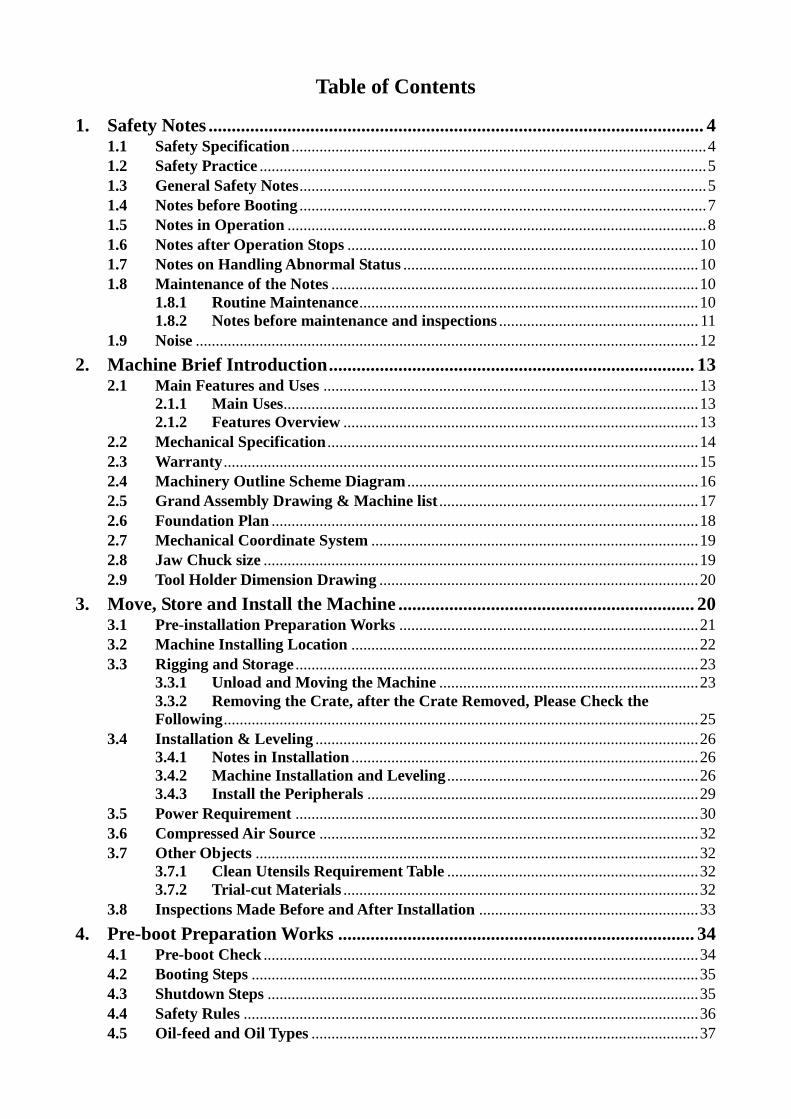
Table of Contents
1. Safety Notes ........................................................................................................... 4 1.1 Safety Specification ........................................................................................................ 4 1.2 Safety Practice ................................................................................................................ 5 1.3 General Safety Notes ...................................................................................................... 5 1.4 Notes before Booting ...................................................................................................... 7 1.5 Notes in Operation ......................................................................................................... 8 1.6 Notes after Operation Stops ........................................................................................ 10 1.7 Notes on Handling Abnormal Status .......................................................................... 10 1.8 Maintenance of the Notes ............................................................................................ 10
1.8.1 Routine Maintenance ..................................................................................... 10 1.8.2 Notes before maintenance and inspections .................................................. 11
1.9 Noise .............................................................................................................................. 12
2. Machine Brief Introduction ............................................................................... 13 2.1 Main Features and Uses .............................................................................................. 13
2.1.1 Main Uses ........................................................................................................ 13 2.1.2 Features Overview ......................................................................................... 13
2.2 Mechanical Specification ............................................................................................. 14 2.3 Warranty ....................................................................................................................... 15 2.4 Machinery Outline Scheme Diagram ......................................................................... 16 2.5 Grand Assembly Drawing & Machine list ................................................................. 17 2.6 Foundation Plan ........................................................................................................... 18 2.7 Mechanical Coordinate System .................................................................................. 19 2.8 Jaw Chuck size ............................................................................................................. 19 2.9 Tool Holder Dimension Drawing ................................................................................ 20
3. Move, Store and Install the Machine ................................................................ 20 3.1 Pre-installation Preparation Works ........................................................................... 21 3.2 Machine Installing Location ....................................................................................... 22 3.3 Rigging and Storage ..................................................................................................... 23
3.3.1 Unload and Moving the Machine ................................................................. 23 3.3.2 Removing the Crate, after the Crate Removed, Please Check the
Following ....................................................................................................................... 25 3.4 Installation & Leveling ................................................................................................ 26
3.4.1 Notes in Installation ....................................................................................... 26 3.4.2 Machine Installation and Leveling ............................................................... 26 3.4.3 Install the Peripherals ................................................................................... 29
3.5 Power Requirement ..................................................................................................... 30 3.6 Compressed Air Source ............................................................................................... 32 3.7 Other Objects ............................................................................................................... 32
3.7.1 Clean Utensils Requirement Table ............................................................... 32 3.7.2 Trial-cut Materials ......................................................................................... 32
3.8 Inspections Made Before and After Installation ....................................................... 33
4. Pre-boot Preparation Works ............................................................................. 34 4.1 Pre-boot Check ............................................................................................................. 34 4.2 Booting Steps ................................................................................................................ 35 4.3 Shutdown Steps ............................................................................................................ 35 4.4 Safety Rules .................................................................................................................. 36 4.5 Oil-feed and Oil Types ................................................................................................. 37

4.5.1 Machine’s Oil-feed Points ............................................................................. 37 4.5.2 Referenced Machine Oils .............................................................................. 37
4.6 Chips Conveyor System ............................................................................................... 38
5. Machine Maintenance and Tuning ................................................................... 39 5.1 Notes in Machine cleanup and Maintenance ............................................................. 39 5.2 Maintenance Period ..................................................................................................... 40
5.2.1 Maintenance Interpretation .......................................................................... 40 5.2.2 Machine Regular Maintenance Frequency List .......................................... 40 5.2.3 Maintenance Check Sheet ............................................................................. 42
5.3 Soft jaw chuck Mechanism.......................................................................................... 44 5.4 Four Way Tool Post Mechanism ................................................................................. 44
5.4.1 Front ................................................................................................................ 45 5.4.2 Side .................................................................................................................. 47
5.5 Two-axis Drive Feed Mechanism ................................................................................ 48 5.6 Mount and Pre-press Adjustment of X-& Z-axis Guide-ways ................................. 48 5.7 Forced Auto Lubricator ............................................................................................... 48
6. Troubleshooting .................................................................................................. 51 6.1 Machine Troubleshooting ............................................................................................ 51 6.2 Quick-Wear Part List .................................................................................................. 52
7. Machine Parts List ............................................................................................. 53

4
1. Safety Notes
While operating the DIAMOND CUT ALLOY WHEEL LATHE, be sure to certify that the
following safety-actions are secured; otherwise, minor consequence of ignorance would
cause degrading of cutting precision, and severe one would result in body injury or even
death.
1.1 Safety Specification
This machine is equipped with safety devices that can protect operator from being hurt or
machine being damaged. Yet, these devices can’t cover all safety issues under notices.
Operator should thoroughly read over this Manual and understand the statements stipulated
in this chapter before operating this Machine. Operator also should pay attention on the
safety-related matter under special environmental conditions and varied materials being
machined.
Hold sufficient space around this Machine used to open the electrical-box door for
maintenance/repair. Assign qualified electrical personnel to wire this Machine from plant
power supply. Voltage input should meet the Machine design; wiring conforms to local
building codes. Operator should not operate this Machine arbitrarily; and should rely on the
safety devices at any circumstance.
Never use inflammables as the cooling liquid. Ignorance of this warning would cause severe
damage.
While Machine is running, the mechanisms such as cutting tools, driving belt, pulleys, the
voltage, compressed air and noise generated would bring certain danger. Prior to operating it,
substantially realize every part of this Machine and strictly obey the safety regulations, in
the respective of minimizing the possibility of hurting operator or damaging Machine.
Before operating, be sure to carefully read the Machine’s operation manuals; strictly obey
the safety regulations and noted instructions; avoid from hurting operator or damaging this
Machine by improper operation.

5
1.2 Safety Practice
At delivery, each Machine is attached with safety devices and labels. Yet, wrong operating
action on this Machine will cause severe accidence. In order to avoid it, every operator must
carefully read over the Operation Manuals made by Top-One and controller supplier;
understand the Machine’s safety mechanism. If any condition you encounter isn’t specified
in the Operation Machine, please inquire the Top-One Machinery Co., Ltd. service center or
its dealer.
Two Operation Manuals are attached along with this Machine:
1. Teaching Manual (maintenance and repair manual): supplied by Top-One Machinery
Co., Ltd.
2. Controllers Operation & Maintenance Manual: supplied by controllers supplier.
Basic safety instructions are presented in below:
Before operating or maintaining this Machine, be sure to obey these safety instructions. Fail
to obey them might cause severe operator’s hurt or Machine’s damage. Every operator must
literally obey these safety instructions.
1.3 General Safety Notes
1. Carefully read this Operation Manual and subsequently understand all parts of this
Machine. If any unclear, inquire it from Top-One Machinery Co., Ltd. or our dealer.
2. Have qualified technical personnel to install, maintain, operate and repair this
Machine.
3. Operator should wear suitable outfit in operation. Do not wear loose one; and take out
ring, watch and other ornaments from hand.
4. Operator should follow work requirements to put on the necessary personal safety
equipment, such as goggles, protection shoes and ear covers, etc.
5. In order to avoid from electric shock, do not have any wet part of your body touch this
Machine.
6. In order to avoid danger from distraction, don’t operate this Machine while having
medication (such as sleeping pills, tranquilizers).
7. Keep the operation-irrelevant persons from closing to this Machine.
8. Provide sufficient luminance (above 500 Lux) in the working zone; timely keep floor
dry.
9. Before performing any maintenance or repair work, shut down the main power source,
avoid from sudden Machine startup that would hurt people or damage the Machine.
10. Do not try to have any part of your body or use any article pass through the
safety-devices-covered area.
11. Keep the working area clean. To avoid from slippery, water, oil or chips made from
cutting process should be cleaned up.
12. In order to avoid from fire or hazard, do not store inflammables or chemicals close to
this Machine.
13. Do not try to modify this Machine, which might jeopardize operator or Machine. To
modify this Machine’s hardware or software, contact your dealer or Top-One

6
Machinery Co., Ltd. for necessary help.
14. Clean up the inner or surrounding of this Machine, use proper cleanup tools. Do not
use compressed air instead.
15. To move workpiece or change tool, be careful on the sharp edge; wear safety gloves to
avoid from being cut by the sharp edge.
16. Regularly clean up the water tank to keep it from being polluted. Perform proper
hands-protection measure to prevent from allergy or cut.
17. Keep the observation window clean. If the transparency is blurred, replace it
immediately. Renew the observation window once per every two years regularly.
18. Prohibit from exposing or operating this Machine in a space with potential explosion
danger.
19. Except for maintenance/repair purpose, do not climb this Machine.
20. If you are stuck inside the Machine, knock the inner protection cover and shout for
help.
21. This Machine is equipped with three-color alarm light to indicate the alarm statuses
(red-danger (push the emergency-stop button), amber-warning (abnormal occurs), and
green-normal in operation).
22. Do not machine the working piece oversize the turning diameter or using over machine
spindle speed to ensure the safety of the working area.
23. Do not put any article on the movable part of Machine or control panel.

7
1.4 Notes before Booting
1. Prior to booting, be sure if there is any leak of oil or unknown liquid around this
Machine and piping.
2. Basically, have one operator to operate this Machine. If under special requirement,
allow the trained operators to help. Yet, if over two persons running this Machine, they
should communicate mutually and timely care about safety.
3. Prior to booting, certify the locations of emergency switch, indicators and operation
switch.
4. Literally obey the warning/indication labels marked on this Machine body.
5. Do not destroy the warning/indication labels marked on this Machine body.
6. Prior to booting, certify that the power cables aren’t damaged; otherwise it might cause
electric shock.
7. Prior to booting, certify that all manometers indicate normal readings.
8. Prior to booting, certify that all indicators work correctly.
9. Prior to booting, certify that both oil and water amount for cutting are sufficient.
10. Prior to booting, certify that all safety covers are closed; prevent chips or cut-coolant
from spraying out to make hazard.
11. Prior to booting, certify that tool is mounted tightly; prevent it from tool-dropping that
causes danger.
12. Prior to booting, certify that workpiece is secured; prevent it from being dropped and
causing danger.
13. Prior to booting, certify that the operating area is clear.
14. Prior to booting, certify that the machining stroke space is clear.
15. Manually run or stop the spine; first, tune the rpm to minimum.
16. Certify that workpiece and tool are under tightly clipped status; start the cutting
condition from minimum machining one.

8
1.5 Notes in Operation
1. While Machine is running, prohibit all protection covers from being opened.
2. No matters under any circumstance, while Machine is running, do not touch it or stand
by the rotating or moving unit of it.
3. When Machine is running, prohibit from accessing the Machine inner space to clean
up chips.
4. Do not touch any switch with wet hand.
5. While spindle is running, to avoid from being hurt by the chip shots, do not stand in
front of it at any circumstance.
6. While Machine is running, prohibit from accessing the Machine inner space to check
workpiece dimensions.
7. Unless under an absolutely required condition, do not take out the telescopic
chip-shield cover.
8. While Machine is running, prohibit from accessing the Machine inner space to put on
or take out the workpiece.
9. While Machine is running, keep hair or other things from being rolled into it.
10. Do not run this Machine without safety devices equipped.
11. While Machine is running, to secure safety, keep irrelevant persons from closing to it.
12. While Machine is running, once power is off, shut down the main power supply switch
immediately.
13. While Machine is running, do not lean on it; it is also dangerous even to lean on the
protection cover.
14. While Machine is running, if any fault or abnormity occurs, shut down all powers
immediately and check/repair it.
15. While Machine is running, do not make any adjustment on it.
16. After the machining process is completed, before taking off workpiece, be sure that the
CYCLE START indicator is off and program-stop indicator (yellow) is lit on.
17. Operator must certify the mounting condition of workpiece.
18. While running this Machine, do not run it over the maximum allowable speed.
19. While running this Machine, do not touch the running workpiece or mechanism by
hand or any other tool.
20. Clamping workpiece and tool tightly is a necessary safety-securing measure; cutting
work should be made from low load to high.
21. While loading/unloading tools by hand, keep feet stand firmly.
22. While Machine is running, keep distance away from its protection cover.
23. When under auto-run process, do not touch any button.
24. Luminance of operating space should be maintained in 500 Lux or higher.
25. After running for long time, the luminance device will become hot; touching it might
make skin-burn in consequence.

9
26. Before pushing “CYCLE START”, certify that “DRY RUN” is null. Start of
spindle-rpm-tuning, two-axis inching and fast-move should be made at proper
positions.
27. While machining, if noise is over 80 dB (A), be sure to put on a hearing-protection
device.
28. Before performing a new program, confirm the program number first. Once the new
program is applied in AUTO mode, run it for just one section.
29. When program is at AUTO mode, don't touch any switch (might cause error
movement).
30. While running or stopping spindle manually, tune the spindle rpm to minimum
position first.
31. When over-stroke occurs, Machine is locked in response. Press “RELEASE” to erase
it. Once released, notice the axis-move direction, not to move toward the
hardware-limit direction.
32. Prohibit from putting any cutting tool or tool onto the operation panel or parts.
33. Avoid from pressing the function button by mistake. Prior to operation, certify the
respective function first.
34. For any workpiece or tool weighing over 10 kg, move it by lifting equipment/device.
35. To clean up chips or change tools, be sure to put on the safety gloves.
36. While sectional operation is over, turn off power and turn it on when next operation
starts.
37. To run special functions, be sure following the instructed order to proceed.

10
1.6 Notes after Operation Stops
1. Before opening the protection cover, be sure that the movable part of Machine (such as
spindle) is stationary already.
2. After dry-cutting process is over and take the workpiece out, be sure to put on safety
gloves (to avoid from the skin-burn).
3. Common settings of panel function switches before power shutdown:
a. Mode switch Manual
b. Spindle speed adjustment switch Minimum
c. Inching or fast displacement adjustment switch Minimum position
d. Mechanical key lock switch Open
1.7 Notes on Handling Abnormal Status
1. Once an abnormal status occurs, press the emergency stop button immediately.
2. Before accessing Machine’s inner space, be sure that the main power supply is shut;
protection cover is open and locked.
3. If stuck inside the Machine, knock the inner plate and shout for help.
1.8 Maintenance of the Notes
1. While performing maintenance works, shut down main power to avoid hurt from
sudden Machine start.
2. To perform maintenance work, be sure that all mechanisms/parts disassembled are put
back after work is done.
3. After work is completed, do not leave any tool or part in the Machine or on the
operation panel.
4. Clean up the chip tank regularly, perform proper hands-protection measure to prevent
from allergy or cut.
5. Keep the observation window clean. If the transparency is blurred, replace it
immediately.
6. Shut down power before adjusting or replacing belts.
1.8.1 Routine Maintenance
(1) Keep the Machine bed clean; make faults easily be found.
(2) Tune the indicating gauges (pneumatic and lube oil) to correct positions.
(3) Ensure that lube oil reaches the guide-way already.

11
1.8.2 Notes before maintenance and inspections
(1) Have qualified electrical engineer wire the HV connections.
(2) Unless agreed by Top-One Machinery Co., Ltd. Software engineer, do not change any
Machine parameter.
(3) Unless necessary, do not climb this Machine.
(4) Do not to remover chips by hands or feet when Machine is not at off status.
(5) The chips-shield cover is equipped to ensure spindle unit operation lifetime; do not
take it off that makes cut-coolant leak into the unit. Timely keep parts that affect
spindle clean.
(6) Solenoid valves will heat up after long time run. Do not hand-touch them right after
Machine is turned off.
(7) Follow the Operation Manual to timely maintain proper oil pressure and guide-way oil
amount.
(8) Follow the Operation Manual using clean guide-way oil; check the oil filter and
oil-supply amount.
(9) Dust-filtering net on the cooling fan of electrical-box should be kept clean.
(10) Machine will be mechanically unstable when foreign matters enter the electric box or
operation box. If not really necessary, don’t open the electrical-box or operation-box
doors.
(11) To replace battery, it should be made at Machine-ON status. If made at OFF status,
some program or parameters might be lost.
(12) Working light is hot after long time running; don’t approach it or touch it by bare hand.
(13) Perform daily and monthly Machine checks per the Operation Manual.
12
1.9 Noise
Per ISO/DIS 230-5 Standard, noise of Machine either at stationary or running status should
be lower than 80 dBA. If over this level, inform us immediately to correct the Machine. The
inspection positions are shown in the figure below.
Measurement standard: according to Machinery Directive 98/38/CE Annex I article 1.7.4(f)
specification.
Spindle speed: 80% of the maximum speed value.
Measuring distance: 1m from the machine housing.
Measurement height: 1.6m from the ground

13
2. Machine Brief Introduction
2.1 Main Features and Uses
2.1.1 Main Uses
The machine is CNC Vertical Wheel Lathe which is design for the repair the cars alloy
wheels.Through CNC, operator can chose AUTO or MANUAL operation to make different
works.
2.1.2 Features Overview
(1) The Machine applies box-type structure; stiffeners are tense; high rigidity; deformation
can be ignored.
(2) The X-axis workbench is with full-stroke support; high loading capability; precision at
any position can be secured.
(3) X- & Z-axis apply the high-precision linear guide-way, ensuring machine’s long-term
accuracy and minimum displacement; and get the high-precision requirement. Z-axis
applies hard-track. The two-axis linear guide-ways apply roller bearings to fit the
rigidity-increasing requirement.
(4) The operation box applies suspension-spin type; facilitate the space application and
operation.
(5) X-axis chip-shield cover is made of high-tension weathering steel plate; durable ad
deforming-free; inclined shape makes cut-coolant and chips flow to the
chips-discharge slot entirely.
(6) Multi-door transparent splash-shield cover; operator can clearly observe the working
status; which protects operator’s safety and improves Machine’s outer appearance.
(7) Accept customer-design machines to meet client’s special requirements.
14
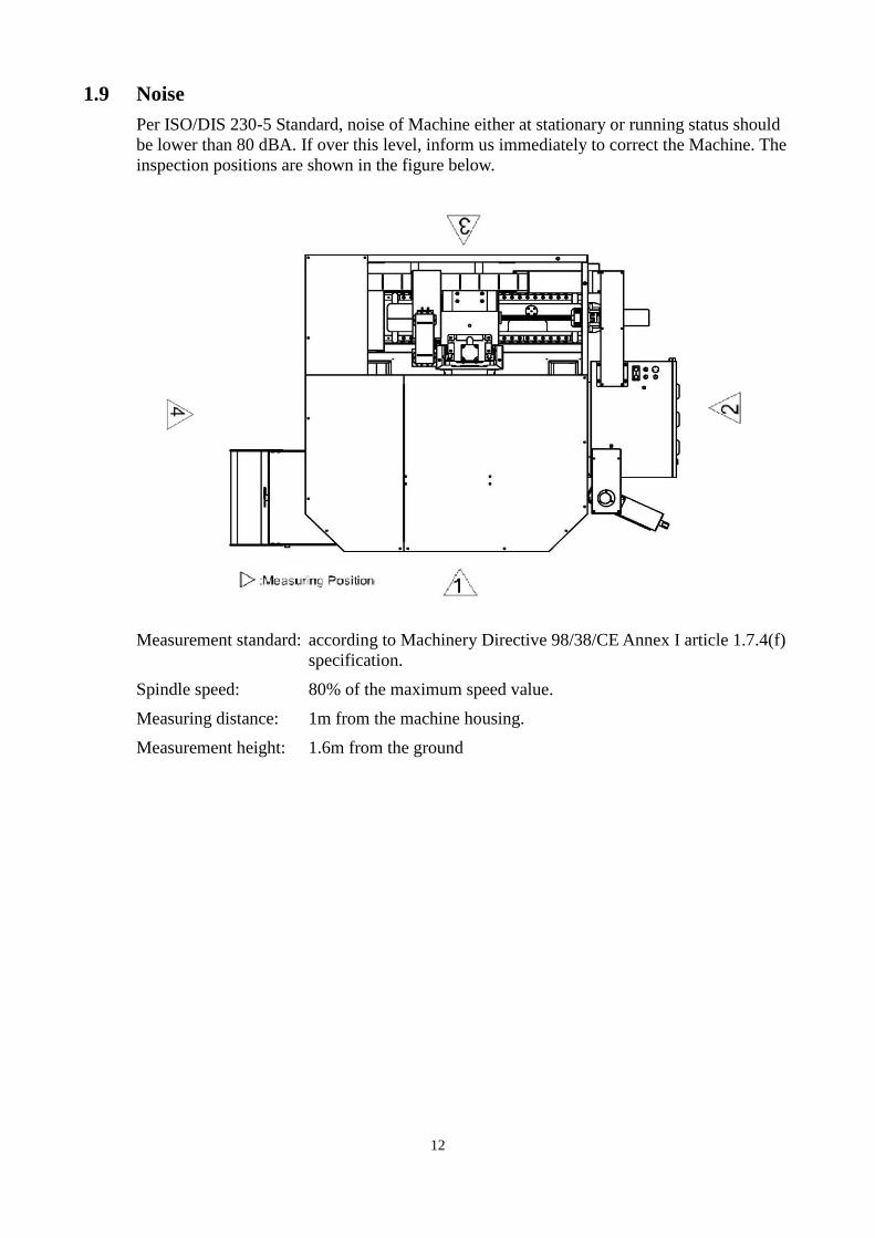
2.2 Mechanical Specification
Note: 1. Due to cotinuous research and development, the machine designs and specifications are
subject to change without prior notice.
2.Custom specifications are available upon request.
Standard accessories: 1. Digitising Package with Wheel Software
2. Diamond Cutter
3. RS-232 & Etherent Ports
4. Full Enclosure
5. Halogen Work Light
6. Auto Lube
7. Way Covers
8. Chip Tray
9. Tools & Tool Box
10. Four Way Tool Post
11. MPG (optional)
VTL30 SPECIFICATION
Model Unit VTL30
Control Control System SYNTEC
Travel
X-axis Travel inch 20"
Z-axis Travel inch 18"
Max.Turning Diameter inch 30"
Table Jaw Chuck(Manual)with Soft Jaw inch 15" - 3
Distance Distance from Spindle end to Table mm 0~18"
Spindle Nose Taper / Tool A2-6
Spindle
Spindle Speed rpm 60~1000
Spindle Type Belt Drive
Spindle Motor KW 10HP/4P
2 axes Servo Motors (X/Z) KW 850W / 850W
Feed
X-axis Rapid Traverse M/min 10 / Direct Drive
Z-axis Rapid Traverse M/min 10 / Direct Drive
Cutting Feedrate M/min 10
Min. Input Unit mm/min 0.001
Installation
Requirements
Connected electricity KVA 15
Weight (about) t 2
15
2.3 Warranty
Under normal operating status, Top-One Machinery Co., Ltd. Offers one-year warranty to its
products, plus technical service and supports, from the date of factory-delivery and buyer
and Top-One Machinery Co., Ltd. Signed the acceptance record. Within the warranty time,
we provide free-charge services and replacing of fault parts; spindle’s warranty is 12 months
or 5,000-hr operation, which reaches first. After warranty time is due, we timely provide
charged technical services, including maintenance consulting, parts supply and in-site
troubleshooting, etc.
1. Faults and damages caused from changing design of this Machine or add extra
attachments to it.
Faults and damages caused from user himself (or assign others) change, dismantle or
modify this Machine or add extra attachments to it.
2. Faults caused from force majeure or improper operation.
(1) Damages or faults caused from force majeure (earthquake, typhoon, fire, flooding,
lightning or abnormal voltage) and environmental facts (sulfide gas, chemicals,
rats or bugs, etc.).
(2) Faults or damages caused from improper operation (outer-force hits, fail to input
designed power source, voltage, pneumatic pressure or hydraulic pressure; or error
operation procedure or machining program compiling, etc).
(3) Faults or damages caused from failing to follow the maintenance (warm-up)
requirements.
3. Consumable parts and accessories.
Consumable parts & accessories in the products, such as luminance tubes (bulbs), rubber
oil tubes, rubber blades, rubber pads, sponge pads, filter nets, power cables, fuses and
batteries that need to be renewed under normal operation, are not covered in warranty.
4. Services made from the following conditions are to be charged.
(1) Exceed warranty expiration date.
(2) Supplement or replace lube oil/crease of products.
(3) Precision or functions not specified in product specification or order contract that
buyer asks for adjustment/modification.
(4) For services made after warranty is due, Top-One will charge for “inspection/test
service fee” even no parts are replaced..
16
2.4 Machinery Outline Scheme Diagram

17
2.5 Grand Assembly Drawing & Machine list

18
2.6 Foundation Plan
19
2.7 Mechanical Coordinate System
Axis-definitions are expressed in below:
X-axis: X-axis is the direction that tool post moves right/left; (+) for right movement and (-)
for left one.
Z-axis: Z-axis is the direction that tool post moves up/down; (+) for up movement and (-)
for down one. tool post
20
2.8 Jaw Chuck size
2.9 Tool Holder Dimension Drawing
21
3. Move, Store and Install the Machine 3.1 Pre-installation Preparation Works
1. Power source: required power supply specification:
Power Voltage Frequency Phase Capacity
Specification 200 ~ 440V 50/60 HZ 3 15 KVA
2. Pneumatic air: air pressure used to clean up spindle, cool down cutting is 5 ~ 7
KG/CM2, at least 90 NL/min of supply.
3. Oils: feed in required oils before starting this Machine:
Purpose Product name Viscosity (40°C) Capacity Remark
Lube oil Guide-way oil 61.2 ~ 74.8 2L ISO VG68,R-68, K68
4. Precision measuring equipment:
1. 0.02mm/M level meter, at least two pieces.
2. Gauge-carried magnetic seat 1/100, 2/1000mm, one or more set each.
3. One granite right-angle ruler.
5. Space requirement:
To plan for Machine layout space, reserve sufficient space for the
operation/maintenance convenience matter. Before planning the Machine’s installation
location, refer to the dimensions shown in “Machinery Outline Scheme Diagram”
specified in Chapter 2 of this Manual making the plan.

22
3.2 Machine Installing Location
1. Machine should be located separate from other ones; keep proper distance between
two machines.
2. Installing location should be free from explosion potential.
3. Reserve sufficient space for maintenance purpose.
4. To install this Machine, keep the Machine door and controller able to be opened and
turned on freely.
5. If electric welding or discharge equipment is located on factory building structure, do
not connect Machine’s grounding cable to the structure.
6. Do not stack articles on the floor around this Machine. Keep the floor dry. If coolant or
lube oil is drained to floor, wipe it out immediately.
7. Keep this Machine and controller away from direct sunbeam.
8. Keep the Machine and controller clean, not be splashed by coolant, lube oil or chips.
9. Keep the Machine and controller free of vibration ≧ 0.5G. Environmental temperature:
0 ~ 35°C; humidity: ≦ 75% RH.
10. Be sure that floor is firm and leveling enough to hold this Machine’s weight; don’t put
this Machine on mud or disqualified foundation surface. Adjust leveling to complete
level.
11. Since this Machine is equipped with many fans, reduce dust to minimum.

23
3.3 Rigging and Storage
This Machine selected forklift capacity must be sufficient (above 2-Ton); otherwise, it
would cause danger in rigging. If lifted by a crane, prepare necessary hoisting steel pipe,
cords and accessories in advance.
3.3.1 Unload and Moving the Machine
1. Unload equipment: 3-Ton folk-lifter x1.
2. Pass chains or hoisting cords through the reserved lugs. If cords are used, add
C-hoist-rings between cords and lugs to protect cords from shear failure.
3. Loosen and remove the supporting mount-devices & screws between Machine and
transporting base plate.
4. Unload the Machine package: (refer to the pictures below)
If Machine is mounted to base plate, use forklift to unload the package from container.
If not, use footpads to rise up Machine in a height above the folk level of forklift.
(1) Unload the Machine as shown in the pictures:

24
(2) Removing the machine from the skid or pallet:
Interpretation of hoisting each different unit:
a. Remove the 2pcs covers in front of X axis telescope cover. Insert a steel bar
inside of the machine base. (See the figure below)
b. Chain down the pass chain through the 2 opener of the sheet metal, loop the
chain around the steel bar from both side of the machine. Then the machine can
be lift up.(See the figure below)
c. Prior to starting the Machining Center, take off the hoisting tools that would hit
and damage the Machining Center.
d. While lifting the chain, it will damage the surface paint; block it out by wooden
board or cloth.

25
5. Notes in moving the Machine:
Obey the following requirements during lifting:
(1) Crane operators should be licensed one.
(2) Strength of lift devices (cranes, cords, lugs & clamps should be sufficient in
bearing this Machine.
(3) Before lifting, carefully check each of the mounting points.
(4) Check that Machine inner space is clear without unnecessary stuff (waste
materials, for example).
(5) Perform team work in lifting operation; make verbal contacts amount the team
members.
(6) After Machine is lifted, operator should keep clear from being exposed on the
Machines area projected to ground.
(7) Check Machine once again. If loose portion is found, tie it up tight.
(8) Lifting capacity of crane/hoist should be sufficient. Before starting to move, get a
balanced status first.
(9) To lift the beam, note the crane height. Table below shows the minimum height
required in lifting the beam.
(10) Prohibit lifting weight over the lifter’s limit.
(11) To lift this Machine, first check if balance is reached.
(12) To prevent from hitting and damaging machine accessories, avoid the lifting
devices from contacting the Machine directly; protect it by pads to the maximum
possible.
(13) Before Machine is stable, do not move, lift or descend it.
(14) In lifting, remove tools, workpiece and peripherals of Machine.
(15) Prior to lifting, be sure that each axis and related accessories are fixed tight.
(16) Assign sufficient manpower to watch every corner; timely communicate for
current status.
3.3.2 Removing the Crate, after the Crate Removed, Please Check the Following
1. Visually check if there is any damage found on Machine mechanisms.
2. Check Machine accessories like aux tools, documents and manuals.
3. Clean up the packing materials after unpacking.
4. Check if rust or paint peel-off is found on Machine mechanisms.
5. Ensure that Machine is placed firmly on the ground.
6. Check if connectors of piping and circuit system are found loose.
7. Check if screws on protection cover plating are loose.
8. Check that Machine follows the specification correctly.
9. Do not dismantle the mount-blocks placed between spindle, head and column.
10. After check is complete, if specification-mismatch, lack of accessories or Machine
damage is found, contact dealer immediately that will provide fast service.
26
3.3.3 Storage
Requirements of storage locations:
1. Environmental temperature: within 5 ~ 40°C.
2. Environmental humidity: below 75% RH.
3. Place on a flat ground/floor.
4. Free from intense dust, acidic gas, corrosive gas or saline air.
5. Free from exposing to direct sunbeam or heat source; ambient temperature varies
widely.
6. Free of abnormal vibration.
7. Free of potential explosion.
3.4 Installation & Leveling
3.4.1 Notes in Installation
1. Luminance at the installed site is suitable for Machine operation and follows related
standard. Light source location shouldn’t influence operator’s visibility or make
operator uncomfortable.
2. Maintenance area is clear without obstacles that hinder opening of electric-box door or
other protection covers.
3. Acting space of workbench should be clear without obstacles.
4. Reserve space for cooling oil tank and chips tank.
5. Free from abnormal vibration, on particular not by an existed press set. If operator
feels vibrations, level (amplitude) below 0.5G is acceptable.
6. Installing place should be flat. If curved, it is hard to level the Machine and cooling oil
tank.
7. Free from being covered with chips, coolant, oil fog or dust made from other
machines.
3.4.2 Machine Installation and Leveling
1. Installation adjustment steps:
(1) While moving the Machine, note the following precaution measure:
a. Only qualified operator can operate forklift.
b. Able to bear Machine’s weight while moving it.
c. Before moving, ensure that X- & Z-axis are secured.
d. Before moving, ensure that no unnecessary stuff is left around the Machine.
e. Carefully put the Machine onto ground; ensure that the Machine’s horizontal
& vertical sides balance each other.
(2) If residual anti-rust paint is left on the guide-way, clean it up completely. If not,
servo-alarm will appear at booting.

27
(3) Remove the mounting fixed block on the X & Z axis slide way.
(4) When the machine set on the floor, Use lever to leveling the machine.
(5) Keep the door interlock switch at ON position; take out the key and put it in a
safe place.
28
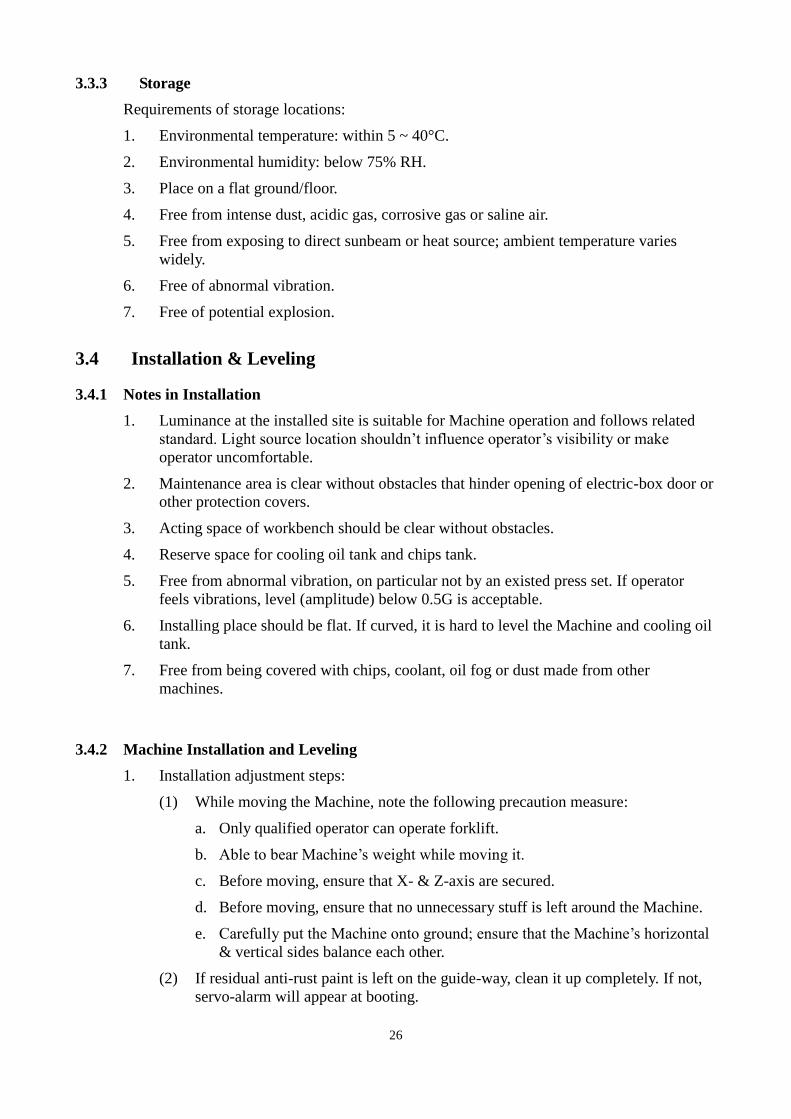
2. Machine leveling adjustment
(1) Use the leveler 0.02 mm/m on the center of the chuck,fix the leveler on the X
axis direction and manual turn the chuck, adjust the level of X axis until the air
bubble in the leveler center. Repeat for Z axis.
29
3.4.3 Install the Peripherals
Installing steps of peripherals
No. Steps Explanation
1 Compressed air
source Send air to the air-input point through hose.
2 Filling track
lubricants Feed in sufficient track lubricant.
3 Remove the mount
block
Remove the mount blocks in X- & Z-axis; don’t remove the
wooden block that supports the spindle head.
4 Mount and install
the wiring lines
Follow the wire numbers connecting and mounting the
dismantled wires/pipes.
5 Electric control After checking the electric control lines, connect them.
6 Turn on power to
make test run
a. Certify the correctness of power phases.
b. Certify the correctness of motor turning direction.
c. Check if pipe connectors are connected correctly and
locked tight; mechanism locations are correct
(mechanism should be located at respective location
normally).
d. Lift the tool post head; take out the supporting pads.
7 Certify track
lubrication
Check if the lube system feeds lube oil? Are two lube oils
distributed properly?
8 Clean Clean the anti-rust oil on jaw chuck & tool post; clean up
dust on Machine and wipe it clean.
9 Commissioning
a. First, manually return Machine’s three axes back to
HOME point manually in slow speed.
b. Return the two axes back to HOME point by 100% fast
speed; certify if the HOME points are same.
c. Check if stroke of each axis follows the set one? If
over-stroke is effective?
d. Follow the attached parameter table to check if
controller’s display meets the parameter table or not?
e. Are the spinning directions and speed of positive/reverse
turns normal?
10 Warm-up run During running, follow the precision inspection table to
make commissioning run.
30
3.5 Power Requirement
1. Only qualified electrical/electronic engineers can perform the wire connect works.
2. Any electronic noise source, such as electric welding machine or discharge equipment,
should not be close to the Machine. Note not let the Machine be affected by
instruments or equipment close to it that makes negative effect.
3. Voltage unstable caused from insufficient power supply will result in controller failure.
4. Power source must be connected to the power distribution panel directly and
independently. Don’t share it with other machines.
Permissible value
Voltage ±10% of voltage (per local voltage)
Frequency 50/60HZ (±1 HZ)
Instant power shutdown Less than 0.01 seconds
Voltage pulse Peak value should not be higher than 200% or lower
than the rms value of stable pulse occurred within
0.0015 sec.
Waveform distortion 7% or less
Stable-voltage uneven 5% or less
5. Keep the Machine’s grounding cable as short as possible; grounding cable diameter is
same to the power-input one.
Level 3 ground: CLASS 3 GROUND.
Ground resistance: 100Ω or less.
6. Power and ground
AC voltage: 3-phase AC 220V ± 10% (main power source is 380V ac; if higher than
415V, lower the voltage over a transformer.)
Frequency: 50 or 60Hz ±1%
Power wire diameter table:
Input voltage (Vac) Current capacity
(A)
Main circuit
breaker (A)
Wire diameter
(mm2)
220 32 40 5.5
380 19 20 3.5
415 17 20 3.5

31
7. Notes in installing power source and grounding work
(1) Follow the Machine’s location to complete power wiring. Refer to the
Foundation Plan.
(2) Follow the applied voltage to select power cable size; and refer to the power
cable diameter table. The grounding cable diameter is 22 mm2.
(3) Do not co-use power cable with other machines. Build an independent power line
for this Machine.
(4) Power cable’s external terminals should be protected by a fuse or breaker.
(5) The grounding resistance should be less than 50Ω.
(6) Grounding line color is yellow-green.
(7) Refer to Fig. 1 (Single set grounding) and Fig. 2 (Multi sets grounding) to make
grounding connection.
(8) For other power line wiring issues, obey the local electric codes to proceed.
Graphic demonstration of machine grounding:
Fig. 1: Single set grounding
Fig. 2: Multi sets grounding
Machine 1 Machine 2 Machine 3
Machine 1 Machine 2 Machine 3

32
3.6 Compressed Air Source
1. Use clean air source.
2. Confirm that the air source can provide necessary air flow-rate.
3. Air pressure should exceed 6 kg/cm2.
4. Accomplish the compressed air supply arrangement before Machine is installed
completely.
5. Arrangement of reserved pipelines:
(1) Compressed air must be filtered and is clean and dry (dew point, 6 kgf/cm2,
10°C).
(2) Supply or compressed air must satisfy Machine’s consumption requirement (1-hp
air compressor that supplies 9 0NL/min is approx. enough).
(3) Refer to the drawing below for the input points of compressed air and power
supply.
The compressed air fast-connector size is 9.525 mm (3/8 in.).
(4) To lay out pipelines, try best to bury the power lines and compressed air line
underground; oil cooler and coolant tank pipelines close to the Machine, avoid
them from trapping and hurt operators. We strongly recommend operator to wear
safety shoes that can reduce the possibility of slipping down and thus causes
hurt.
3.7 Other Objects
3.7.1 Clean Utensils Requirement Table
Name Specification/Quantity Remark
Kerosene 1L Used to clean the Machine
Non-volatile cleaning agents 0.5L Used to clean the Machine
Rag 10 pieces Used to clean the Machine
Fur brush 1 piece Used to clean the Machine
3.7.2 Trial-cut Materials
If making workpiece test, client needs to prepare for the related materials, tools, jigs and
machining program.
33
3.8 Inspections Made Before and After Installation
1. After Machine installation work is done, check the following items before booting:
(1) Ensure that all bolts are locked.
(2) Ensure that all electronic connectors are plugged.
(3) Ensure that all hydraulic holes and water pipes are connected.
(4) If Machine has optional accessories attached on it, ensure that all cables and
hydraulic pipes are connected correctly.
(5) Check if electric voltage and R/S/T phases are all correct?
2. Check the following items after booting:
(1) Do not make two-axis feeding right after booting. warm up first after booting.
(2) Check if oil is leaking. Ensure that all indicators indicate at the correct positions.
(3) Ensure that all mount-rack (device for transporting purpose are removed.

34
4. Pre-boot Preparation Works
4.1 Pre-boot Check
In order to secure the safety of operators and Machine, literally check the following items
before booting, that can certify the Machine’s precision and lifetime.
1. Check if oils in the lube oil tank are sufficient?
2. Ensure that spaces around the Machine and control system are clear.
3. Ensure that every control system door is closed.
4. Ensure that all control switches are at good condition.
5. Is there anyone in the Machine’s dangerous area?
6. Does operator wear neat outfit and put on personal protection devices?
7. Clean up residual water in the air pressure regulators filter.
8. Certify that power and control line connection points are well connected; no broken is
found on the lines.
9. Check if compressed air, lubrication, hydraulic and cooling system pipelines are free
from broken or leak?
10. Remove work-irrelevant articles stacking around the Machine.
11. Certify that all protection shields, doors and covers are closed and secured completely.
12. Certify that screws on jigs/features are all locked.
13. Check and make sure that all safety devices work functionally.
14. Certify that tools in spindle are all locked.

35
4.2 Booting Steps
1. Push the power switch to ON position; now the spindle motor fan start running; both
heat exchanger and electric control box fans also start running.
2. Press down the POWER ON button on NC control of operation box; after a while,
CRT shows texts and NC READY hydraulic power is supplied (if the E-STOP on the
operation box is at pull-down position, CRT displays NC NOT READY; which means
NC isn’t ready yet; hydraulic power isn’t supplied either. To make NC normal, it must
press the E-STOP button, and turn it in CCW direction to make E-STOP button jump
up).
3. Certify that is CRT displaying abnormal message? Are Button signal indicators on the
operation panel at normal positions and lit on? Then, certify if hydraulic pressure and
air pressure are normal? When all are normal, operation is ready.
4. Shift three axes to proper positions, then, move back to HOME point; now booting is
complete and standby for operation. Yet, to ensure machining precision, it’s better
warm-up for 510 minutes to let three axes and spindle make necessary drive run that
can stabilize the precision.
5. Check the oil-supply at each guide-way surface.
6. Check if luminance equipment is normal.
7. After initiation, check if Machine runs with noise or abnormity?
8. Check if power is supplying normally?
9. Check if any broken point is found on pipelines and cable lines?
10. Check if there is any water or oil leak while Machine is running?
11. Check if any moving mechanism makes vibration, shake or abnormal action?
12. Check if actual machining precision is within the allowable tolerance?
4.3 Shutdown Steps
1. If tool post is with tools, it’s better to take tools out and empty the tool post.
2. After daily operation is over, check if Machine has abnormal status?
3. Regularly clean up the filter nets of electric-box cooler and spindle cooler.
4. When the chips tank is full, clean up it immediately.
5. Solenoid valves or electric devices are hot after operation is over and power shutdown;
don’t touch them that will cause skin-burn.
6. When a mechanism’s oil-feed is insufficient, follow this Manual statements to
supplement it. When oil color changes, the oil degrades already; renew it immediately.
7. After cutting operation is over, clean up chips inside the Machine immediately.
8. Shift each axis to a proper position (spindle head better is shifted to middle position).
9. Clean up the Machine or perform anti-rust work.
10. Press the NC POWER OFF button on the operation box.
11. Turn the power control switch to OFF position.
12. Machine shutdown is completed.

36
4.4 Safety Rules
1. Before booting, familiar with the Operation Manual first.
2. Prohibit running this Machine beyond its scope specified in the usage specification.
3. Do not clean chips during machining process.
4. Prior to machining, ensure that workpiece is mounted correctly.
5. Before starting this Machine, check the distance between tools, workpiece and jigs
first.
6. Prohibit using incorrect cutting tool or tool; for example: the blunt cutting tool or
unsecured tool.
7. While Machine is running, prohibit using any matter to wipe or adjust the tools.
8. Prohibit stopping or slowing down this Machine by hand or other substitutes.
9. Before machining, ensure that all safety covers/doors are closed.
10. Prohibit running this Machine under no-operator status.
11. When spindle is running, prohibit tuning cut-coolant flow-rate or air-spray flow-rate.
12. While measuring the workpiece, be sure that this Machine is stationary.
13. Prohibit using compressed air to sweep this Machine.
14. Keep the surrounding space of this Machine clean; remove unwanted obstacles or
chips.
15. If any Machine-using oil leaks, repair it immediate; avoid making floor wet.
16. When Machine is running, prohibit making maintenance or lubrication work.
17. While performing Machine maintenance, repair or lubrication, controller’s operation
panel must be properly labeled or locked; it’s better assigning person to watch it.
18. Never replace the current parts by a bad-quality one.
19. Never touch the controller or switch by wet hand.
20. When there is an electric fault, have an electric engineer to repair it.
21. When Machine has noise or loose condition, run it after being checked/repaired and
this Machine is under normal status.
37
4.5 Oil-feed and Oil Types
1. The Machine two axis guide-ways and ball screw are under forced-lubrication
operation with auto oil-feeding.
2. Prior to booting, check if lube oil is sufficient; properly fill it.
3. Must use correct lube oil; incorrect one under use will reduce Machine’s lifetime and
cause malfunction.
4. Lube oil flow-rate is tuned to the design point before delivery. Unless the loop is
clogged or fault, do not adjust it by yourself.
4.5.1 Machine’s Oil-feed Points
The following diagram presents the Machine’s oil-feed points. While feeding or replacing
oil, do it at the specified oil-feed points (see the recommended oil list shown in next page).
4.5.2 Referenced Machine Oils
Recommended oil list:
Position Spot-check/oil-change
cycle Method
Oil tank
capacity
(Unit: L)
Recommended oil
specification
Oil-feeder
Daily spot-check
When lube-oil-low
alarm appears
Renew it once per
every six months
Feed oil to the upper
limit of oil gauge 2
ISO VG68
MOBIL, DTE 26
SHELL, TELLUS 68
ESSO, TERESSO 68
CASTROL, ALPHASP 68

38
4.6 Chips Conveyor System
Chips conveyor system N/A in this Machine, Please manually clean the chips, sweep the
chips to the front left corner where the chip tank located.
39
5. Machine Maintenance and Tuning
A good machine needs excelled operator with proper regular maintenance & checks, to
operate it at best condition. If small problem isn’t improved immediately, it may cause
machine’s fault and result in severe consequence. Therefore, normal operation should be
literally done per the prevention maintenance rules. Below is the detailed illustration of
maintenance periods and tuning methods on varied mechanisms. If any condition you
encounter isn’t specified in the Operation Machine, or unable to be solved, please notice our
Maintenance Dept to handle it.
5.1 Notes in Machine cleanup and Maintenance
Clean the Machine:
All painted surfaces need to be cleaned. wash the bright and black-dyed anti-rust surface.
Notes in maintenance:
(1) After washing over the sliding portion, lube the oil-lubed surface immediately. Lube
the drive screw and note if the pathway is smooth.
(2) Every day before booting this Machine, repeat this action once per each 2-4 hours.
Increase the lubricating times for the frequently sliding portions.
(3) After daily work is done, clean chips and dust on Machine’s sliding portions.
(4) Annually follow the precision check sheet to check precisions of different portions;
replace the lube oil.
(5) Do not step on the telescopic covers, nor put any article on it.
(6) Non-operating person should act outside the safety-limit area.
40
5.2 Maintenance Period
5.2.1 Maintenance Interpretation
When Machine is running, Machine body or its parts will be corroded or worn speed
increases due to dust, moisture, oil or oil fog, etc. Regular maintenance can extend
Machine’s operation lifetime and maintain its working efficiency.
In this section we’ll provide the maintenance methods of systems/units and suggested
maintenance schedule. When performing maintenance, substantially obey the methods/time
presented in this section.
5.2.2 Machine Regular Maintenance Frequency List
Machine regular maintenance frequency list (1/3)
Maintenance work content
Dai
ly
mai
nte
nan
ce
Wee
kly
mai
nte
nan
ce
Mo
nth
ly
mai
nte
nan
ce
Hal
f y
ear
mai
nte
nan
ce
Yea
rly
mai
nte
nan
ce
Remark
Pn
eum
atic
syst
em
Check pneumatic air pipelines D W M H Y
Check the air pressure D W M H Y

41
Machine regular maintenance frequency list (3/3)
Maintenance work content
Dai
ly
mai
nte
nan
ce
Wee
kly
mai
nte
nan
ce
Mo
nth
ly
mai
nte
nan
ce
Hal
f y
ear
mai
nte
nan
ce
Yea
rly
mai
nte
nan
ce
Remark O
il-f
eed
er
Check lube oil level D W M H Y
Check oil-feed pressure W M H Y
Op
erat
ion
pan
el
Check indicators on panel D W M H Y
Check switches on panel D W M H Y
Ele
ctri
cal
bo
x
Clean up heat exchanger filter W M H Y
Clean electrical box M H Y
Clean electrical components M H Y
Lock up devices in electric-box M H Y
Oth
er
Clear jaw chuck chips D W M H Y
Clear machine chips D W M H Y
Clean up chips in X-, Z-axis cover D W M H Y
X-axis cover oiling W M H Y
Locking tool holder D W M H Y
Clean up chips on tool holder D W M H Y
Check two axes track H Y
Check two axes screw H Y
Clean up chips on anchor bolts M H Y
Anchor bolts oiling M H Y
Check the tightness of anchor bolts H Y
Clean up chips in flexible shielding
tube M H Y
Check pipeline in shielding tube M H Y
Check flexible shielding tube H Y
Clean up chips on top of column D W M H Y
Discharge recycled lube oil from
two-axis W M H Y
42
5.2.3 Maintenance Check Sheet
1. Daily maintenance sheet
Model/Machine No.: /
Maintenance date: By: Confirmed:
Daily maintenance
Item Maintenance work Maintenance
type Checked/confirmed Remark
01 Check air pressure of air-pressure
regulator DWMHY □Accomplished □Not performed
02 Clean up chips in chips tank DWMHY □Accomplished □Not performed
03 Check if oil in oil-feeder is sufficient DWMHY □Accomplished □Not performed
04 Check if the indicators on the board
are all normal DWMHY □Accomplished □Not performed
05 Check if the switches on the board are
all normal DWMHY □Accomplished □Not performed
06 Clean up chips on jaw chuck DWMHY □Accomplished □Not performed
07 Clean up chips in machine DWMHY □Accomplished □Not performed
08 Clean up chips in X-, Z-axis cover DWMHY □Accomplished □Not performed
09 Locking tool holder and pull handle DWMHY □Accomplished □Not performed
10 Clean up chips sticking on tool holder DWMHY □Accomplished □Not performed
11 Clean up chips on column DWMHY □Accomplished □Not performed
2. Weekly maintenance sheet
Model/Machine No.: /
Maintenance date: By: Confirmed:
Weekly maintenance
Item Maintenance work Maintenance
type Checked/confirmed Remark
12 Check if oil-feeding pressure of
oil-feeder is normal WMHY □Accomplished □Not performed
13 Clean up dust on electric-box fan WMHY □Accomplished □Not performed
14 Jaw chuck surface antirust-oiling WMHY □Accomplished □Not performed
15 Antirust-oiling and lubrication of X-
protection covers WMHY □Accomplished □Not performed
16 Tool holder antirust-oiling WMHY □Accomplished □Not performed
17 Discharge recycled lube oil from
three-axis WMHY □Accomplished □Not performed

43
3. Monthly maintenance sheet
Model/Machine No.: /
Maintenance date: By: Confirmed:
Monthly maintenance
Item Maintenance work Maintenance
type Checked/confirmed Remark
18 Clean fan filter MHY □Accomplished □Not performed
19 Clean up dust and foreign matter in
electrical-box MHY □Accomplished □Not performed
20 Clean up dust on electric devices MHY □Accomplished □Not performed
21 Adjust and lock up electric devices MHY □Accomplished □Not performed
22 Clean up chips on anchor bolts MHY □Accomplished □Not performed
23 Anchor bolts antirust-oiling MHY □Accomplished □Not performed
24 Clean up chips in flexible shielding
tube MHY □Accomplished □Not performed
25 Check if the piping layout inside
shield tube is normal MHY □Accomplished □Not performed
4. Yearly maintenance sheet
Model/Machine No.: /
Maintenance date: By: Confirmed:
Yearly maintenance
Item Maintenance work
Maintenance
type Checked/confirmed Remark
26 Check if the tracks of two-axis are
normal HY □Accomplished □Not performed
27 Check if thescrews of two-axis are
normal HY □Accomplished □Not performed
28 Check if anchor bolts are normal HY □Accomplished □Not performed
29 Check if flexible shielding tube is
normal HY □Accomplished □Not performed
44
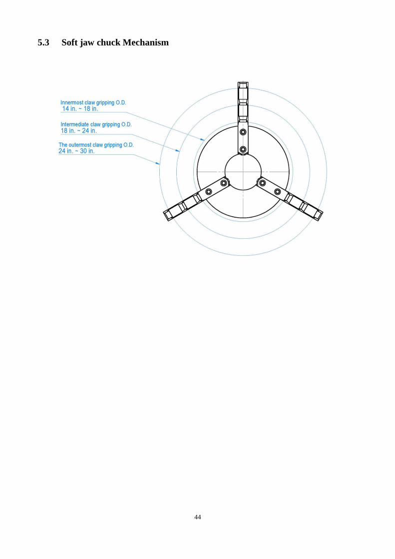
5.3 Soft jaw chuck Mechanism

45
5.4 Four Way Tool Post Mechanism
5.4.1 Front
1. Locate the probe base on the four way tool post. Prior to installation be sure that the position of
the probe base faces the left side as shown in the figure.
2. When installing turn the tool post so that the probe base is on top. Place the probe on top of the
base as shown in the figure.
3. On the side of the probe base there are two set screws, tighten them to secure the probe. Note:
When turning the four way tool post, make sure your probe will not hit any object.
4. Locate the metal back support below the probe base. This helps straightening out your cutter
during installment.
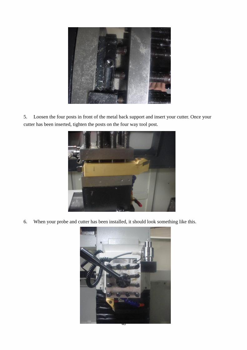
46
5. Loosen the four posts in front of the metal back support and insert your cutter. Once your
cutter has been inserted, tighten the posts on the four way tool post.
6. When your probe and cutter has been installed, it should look something like this.
47
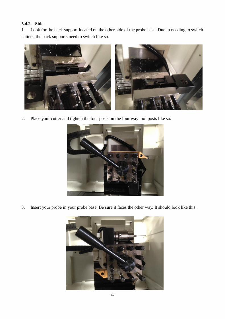
5.4.2 Side
1. Look for the back support located on the other side of the probe base. Due to needing to switch
cutters, the back supports need to switch like so.
2. Place your cutter and tighten the four posts on the four way tool posts like so.
3. Insert your probe in your probe base. Be sure it faces the other way. It should look like this.
48
5.5 Two-axis Drive Feed Mechanism
The X- & Z-axis drive feed system is driven by AC servomotor, power is transmitted to
X-axis column, Z-axis to move through coupling and ball screw.
Apply the pre-pressed double-nut ball screw.
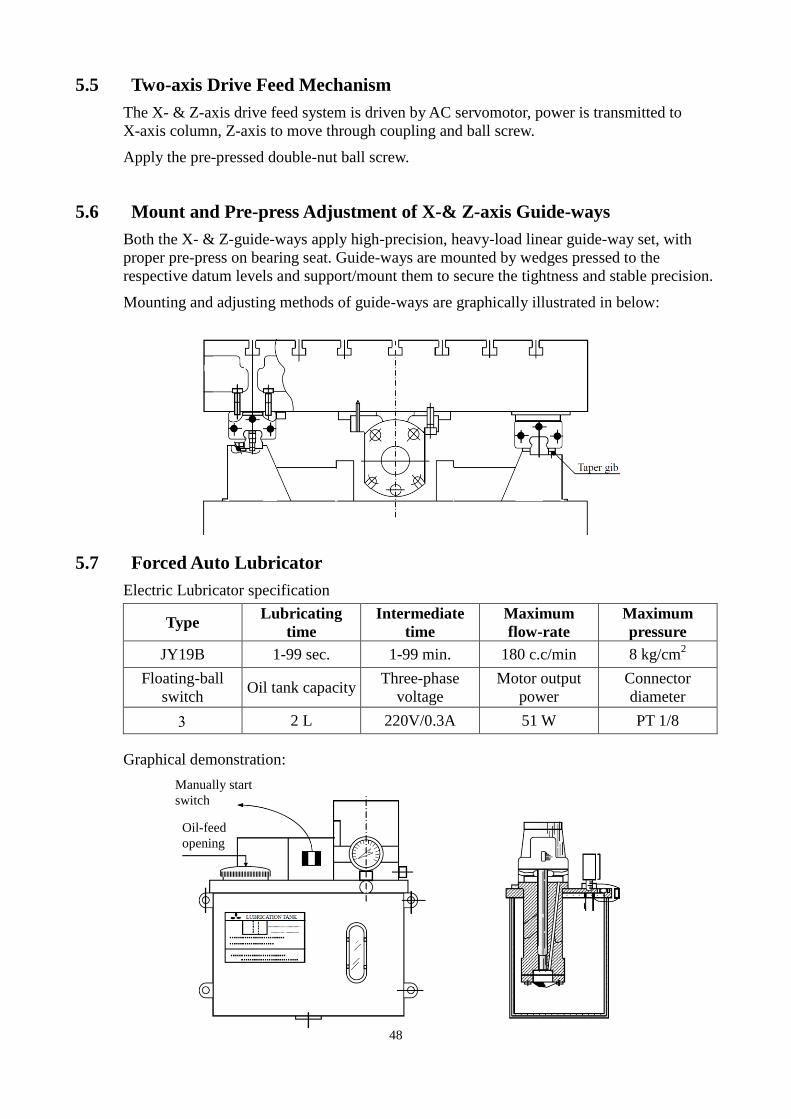
5.6 Mount and Pre-press Adjustment of X-& Z-axis Guide-ways
Both the X- & Z-guide-ways apply high-precision, heavy-load linear guide-way set, with
proper pre-press on bearing seat. Guide-ways are mounted by wedges pressed to the
respective datum levels and support/mount them to secure the tightness and stable precision.
Mounting and adjusting methods of guide-ways are graphically illustrated in below:
5.7 Forced Auto Lubricator
Electric Lubricator specification
Type Lubricating
time
Intermediate
time
Maximum
flow-rate
Maximum
pressure
JY19B 1-99 sec. 1-99 min. 180 c.c/min 8 kg/cm2
Floating-ball
switch Oil tank capacity
Three-phase
voltage
Motor output
power
Connector
diameter
2 L 220V/0.3A 51 W PT 1/8
Graphical demonstration:
Manually start
switch
Oil-feed
opening
49
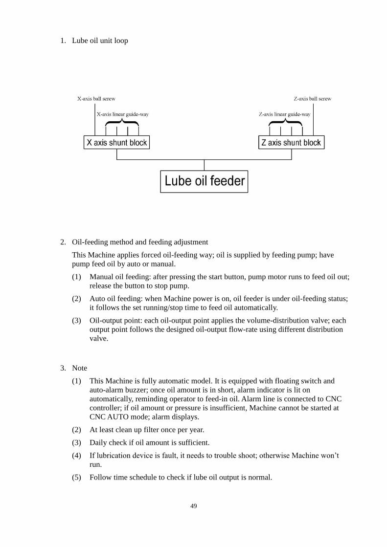
1. Lube oil unit loop
2. Oil-feeding method and feeding adjustment
This Machine applies forced oil-feeding way; oil is supplied by feeding pump; have
pump feed oil by auto or manual.
(1) Manual oil feeding: after pressing the start button, pump motor runs to feed oil out;
release the button to stop pump.
(2) Auto oil feeding: when Machine power is on, oil feeder is under oil-feeding status;
it follows the set running/stop time to feed oil automatically.
(3) Oil-output point: each oil-output point applies the volume-distribution valve; each
output point follows the designed oil-output flow-rate using different distribution
valve.
3. Note
(1) This Machine is fully automatic model. It is equipped with floating switch and
auto-alarm buzzer; once oil amount is in short, alarm indicator is lit on
automatically, reminding operator to feed-in oil. Alarm line is connected to CNC
controller; if oil amount or pressure is insufficient, Machine cannot be started at
CNC AUTO mode; alarm displays.
(2) At least clean up filter once per year.
(3) Daily check if oil amount is sufficient.
(4) If lubrication device is fault, it needs to trouble shoot; otherwise Machine won’t
run.
(5) Follow time schedule to check if lube oil output is normal.

50
4. Troubleshooting of lubrication unit
Item Fault status Reason Troubleshooting method
1 Oil output fails
to output oil
1. Pipeline is clogged.
2. Lube oil viscosity is too high.
3. Filter net is clogged.
4. Oil amount is insufficient.
5. Floating switch is fault.
6. Check valve is clogged.
7. Pump parts fault.
8. Pipe leaks.
1. Clean up or replace pipeline.
2. Change to qualified oil.
3. Remove clogging.
4. Feed oil.
5. Replace.
6. Remove clogging.
7. Repair.
8. Replace pipeline.
2 Alarm appears
1. Pressure switch is
short-circuited.
2. Pipe leaks.
3. Pumping pressure is not
enough.
1. Replace pressure switch or
cable.
2. Replace pipeline.
3. Repair pump.
4. Replace pump.
3
Oil-feeding
flow-rate is
wrong
1. Wear of parts is over.
2. Oil seal is not tight.
1. Replace to other model.
2. Replace.
51
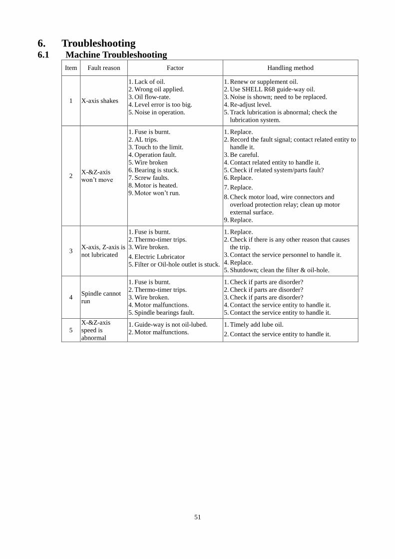
6. Troubleshooting 6.1 Machine Troubleshooting
Item Fault reason Factor Handling method
1 X-axis shakes
1. Lack of oil.
2. Wrong oil applied.
3. Oil flow-rate.
4. Level error is too big.
5. Noise in operation.
1. Renew or supplement oil.
2. Use SHELL R68 guide-way oil.
3. Noise is shown; need to be replaced.
4. Re-adjust level.
5. Track lubrication is abnormal; check the
lubrication system.
2 X-&Z-axis
won’t move
1. Fuse is burnt.
2. AL trips.
3. Touch to the limit.
4. Operation fault.
5. Wire broken
6. Bearing is stuck.
7. Screw faults.
8. Motor is heated.
9. Motor won’t run.
1. Replace.
2. Record the fault signal; contact related entity to
handle it.
3. Be careful.
4. Contact related entity to handle it.
5. Check if related system/parts fault?
6. Replace.
7. Replace.
8. Check motor load, wire connectors and
overload protection relay; clean up motor
external surface.
9. Replace.
3 X-axis, Z-axis is
not lubricated
1. Fuse is burnt.
2. Thermo-timer trips.
3. Wire broken.
4. Electric Lubricator
5. Filter or Oil-hole outlet is stuck.
1. Replace.
2. Check if there is any other reason that causes
the trip.
3. Contact the service personnel to handle it.
4. Replace.
5. Shutdown; clean the filter & oil-hole.
4 Spindle cannot
run
1. Fuse is burnt.
2. Thermo-timer trips.
3. Wire broken.
4. Motor malfunctions.
5. Spindle bearings fault.
1. Check if parts are disorder?
2. Check if parts are disorder?
3. Check if parts are disorder?
4. Contact the service entity to handle it.
5. Contact the service entity to handle it.
5
X-&Z-axis
speed is
abnormal
1. Guide-way is not oil-lubed.
2. Motor malfunctions.
1. Timely add lube oil.
2. Contact the service entity to handle it.

52
6.2 Quick-Wear Part List

53
7. Machine Parts List
54
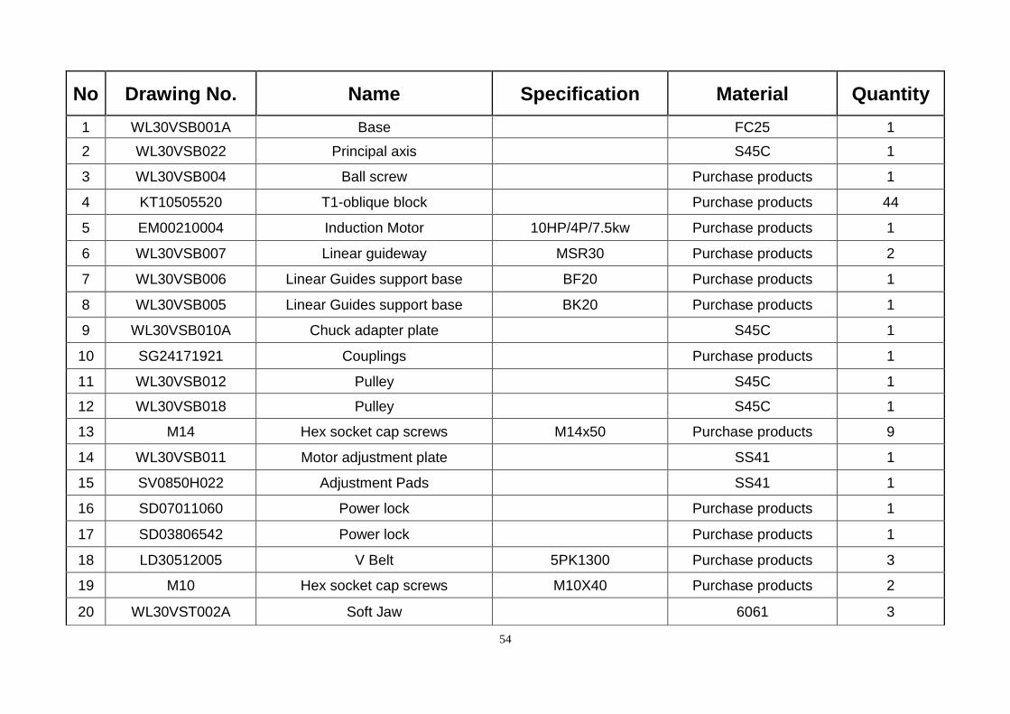
No Drawing No. Name Specification Material Quantity
1 WL30VSB001A Base FC25 1
2 WL30VSB022 Principal axis S45C 1
3 WL30VSB004 Ball screw Purchase products 1
4 KT10505520 T1-oblique block Purchase products 44
5 EM00210004 Induction Motor 10HP/4P/7.5kw Purchase products 1
6 WL30VSB007 Linear guideway MSR30 Purchase products 2
7 WL30VSB006 Linear Guides support base BF20 Purchase products 1
8 WL30VSB005 Linear Guides support base BK20 Purchase products 1
9 WL30VSB010A Chuck adapter plate S45C 1
10 SG24171921 Couplings Purchase products 1
11 WL30VSB012 Pulley S45C 1
12 WL30VSB018 Pulley S45C 1
13 M14 Hex socket cap screws M14x50 Purchase products 9
14 WL30VSB011 Motor adjustment plate SS41 1
15 SV0850H022 Adjustment Pads SS41 1
16 SD07011060 Power lock Purchase products 1
17 SD03806542 Power lock Purchase products 1
18 LD30512005 V Belt 5PK1300 Purchase products 3
19 M10 Hex socket cap screws M10X40 Purchase products 2
20 WL30VST002A Soft Jaw 6061 3

55
No Drawing No. Name Specification Material Quantity
21 WL30VSB019 Headstock FC25 1
22 WL30VSB021 Spindle the front cover SS41 1
23 BH30216080 Tapered roller bearings 30216 Purchase products 1
24 BH30215075 Tapered roller bearings 30215 Purchase products 1
25 WL30VSB020 Bearing gland SS41 1
26 B601407002 Bearing 6014 Purchase products 1
27 WL30VST003 Chuck 15 in. Purchase products 1
28 WL30VSB024 Drain oil fittings SS41 2
29 BD1102B902 Foundation Bolts Purchase products 8
30 WL30VSB024 Spindle cover plate SS41 1
31 WL30VSC016 Motor mount SS41 1
32 ES50932085B Servomotor YASKAWA-0.85KW Purchase products 1
33 YF04015058 Precision lodnuts YSF Purchase products 1
34 WL30VSB025 Telescopic covers Purchase products 1
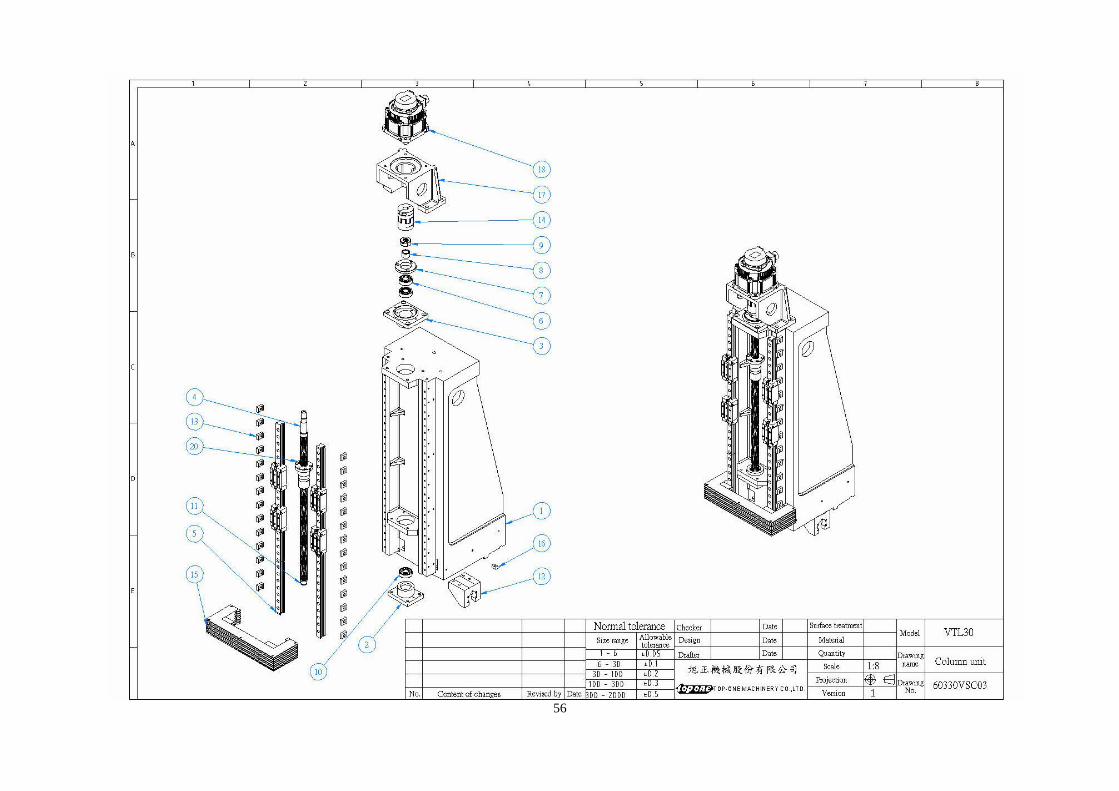
56
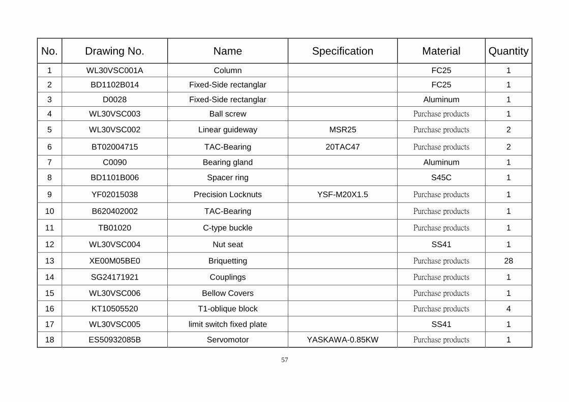
57
No. Drawing No. Name Specification Material Quantity
1 WL30VSC001A Column FC25 1
2 BD1102B014 Fixed-Side rectanglar FC25 1
3 D0028 Fixed-Side rectanglar Aluminum 1
4 WL30VSC003 Ball screw Purchase products 1
5 WL30VSC002 Linear guideway MSR25 Purchase products 2
6 BT02004715 TAC-Bearing 20TAC47 Purchase products 2
7 C0090 Bearing gland Aluminum 1
8 BD1101B006 Spacer ring S45C 1
9 YF02015038 Precision Locknuts YSF-M20X1.5 Purchase products 1
10 B620402002 TAC-Bearing Purchase products 1
11 TB01020 C-type buckle Purchase products 1
12 WL30VSC004 Nut seat SS41 1
13 XE00M05BE0 Briquetting Purchase products 28
14 SG24171921 Couplings Purchase products 1
15 WL30VSC006 Bellow Covers Purchase products 1
16 KT10505520 T1-oblique block Purchase products 4
17 WL30VSC005 limit switch fixed plate SS41 1
18 ES50932085B Servomotor YASKAWA-0.85KW Purchase products 1
58
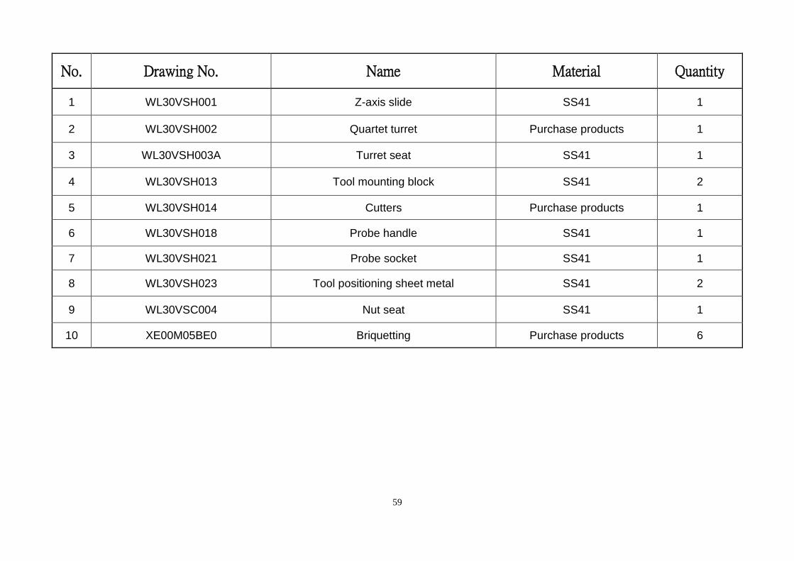
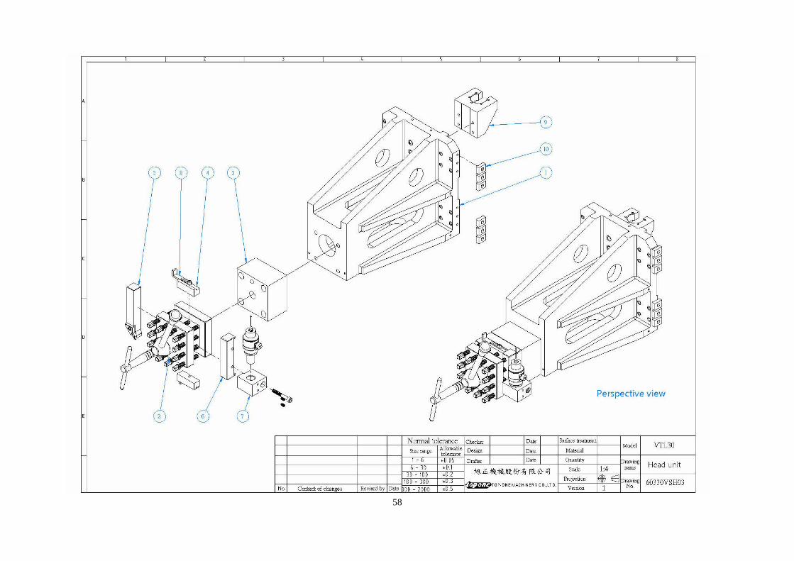
59
No. Drawing No. Name Material Quantity
1 WL30VSH001 Z-axis slide SS41 1
2 WL30VSH002 Quartet turret Purchase products 1
3 WL30VSH003A Turret seat SS41 1
4 WL30VSH013 Tool mounting block SS41 2
5 WL30VSH014 Cutters Purchase products 1
6 WL30VSH018 Probe handle SS41 1
7 WL30VSH021 Probe socket SS41 1
8 WL30VSH023 Tool positioning sheet metal SS41 2
9 WL30VSC004 Nut seat SS41 1
10 XE00M05BE0 Briquetting Purchase products 6