diana: a machine learning mechanism for adjusting the tdd...
TRANSCRIPT

Research ArticleDIANA: A Machine Learning Mechanism for Adjusting the TDDUplink-Downlink Configuration in XG-PON-LTE Systems
Panagiotis Sarigiannidis,1 Antonios Sarigiannidis,2
Ioannis Moscholios,3 and Piotr Zwierzykowski4
1Department of Informatics and Telecommunications Engineering, University of Western Macedonia, 501 00 Kozani, Greece2Department of Economics, Democritus University of Thrace, University Campus, 691 00 Komotini, Greece3Department of Informatics and Telecommunications, University of Peloponnese, 221 00 Tripoli, Greece4Faculty of Electronics and Telecommunications, Poznan University of Technology, 60-965 Poznan, Poland
Correspondence should be addressed to Panagiotis Sarigiannidis; [email protected]
Received 22 February 2017; Revised 15 May 2017; Accepted 31 May 2017; Published 19 July 2017
Academic Editor: Massimo Condoluci
Copyright © 2017 Panagiotis Sarigiannidis et al.This is an open access article distributed under the Creative Commons AttributionLicense, which permits unrestricted use, distribution, and reproduction in anymedium, provided the originalwork is properly cited.
Modern broadbandhybrid optical-wireless access networks have gained the attention of academia and industry due to their strategicadvantages (cost-efficiency, huge bandwidth, flexibility, and mobility). At the same time, the proliferation of Software DefinedNetworking (SDN) enables the efficient reconfiguration of the underlying network components dynamically using SDN controllers.Hence, effective traffic-aware schemes are feasible in dynamically determining suitable configuration parameters for advancingthe network performance. To this end, a novel machine learning mechanism is proposed for an SDN-enabled hybrid optical-wireless network. The proposed architecture consists of a 10-gigabit-capable passive optical network (XG-PON) in the networkbackhaul and multiple Long Term Evolution (LTE) radio access networks in the fronthaul. The proposed mechanism receivestraffic-aware knowledge from the SDN controllers and applies an adjustment on the uplink-downlink configuration in the LTEradio communication. This traffic-aware mechanism is capable of determining the most suitable configuration based on the trafficdynamics in thewhole hybrid network.The introduced scheme is evaluated in a realistic environment using real traffic traces such asVoice over IP (VoIP), real-time video, and streaming video. According to the obtained numerical results, the proposed mechanismoffers significant improvements in the network performance in terms of latency and jitter.
1. Introduction
Modern telecommunication networks become increasinglycomplicated with various features and potentials. Theirambition is to provide end-users with ubiquitous access toadvanced services and applications at a high-efficiency andhigh-quality level in a cost-efficient manner, any time, anyplace. Academia, industry, and emerging communities, thatis, the 5thGeneration (5G) Infrastructure Public Private Part-nership (5G-PPP), promote the integration of the mobile andwireless with the wired and optical communications, givenlicensed and unlicensed spectrum features, while supportingthe ubiquitous communication access to the last (or first)mile. Still, the access network domain, defined as the domainbetween the central office (CO) and the end-user connectionpoints (e.g., home, curve, or building), remains the most
arduous bottleneck in modern telecommunication networks.The ambitious challenge of upgrading the old copper-basedinfrastructure with modern optical networking componentsis still open. Even though during the last decade the capacityof core networks has experienced significant growth to meetthe increasing bandwidth requirements, access networksconstitute one of the trickiest puzzles [1].
Modern access networks are in front of three mainchallenges: (a) they have to be advanced in programmablecomponents, (b) they have to support virtualization, and (c)they have to support high bandwidth to meet the latest userrequirements. Software Defined Networking (SDN) technol-ogy seems promising to provide efficient solutions for thefirst challenge through a novel design principle that emergesto separate the control and the data plane functions. Inessence, SDN enables the network programmability through
HindawiMobile Information SystemsVolume 2017, Article ID 8198017, 15 pageshttps://doi.org/10.1155/2017/8198017
2 Mobile Information Systems
which the dynamic initialization, control, manipulation, andmanagement in the access network are feasible [2]. Net-work Function Virtualization (NFV) employs standard ITvirtualization technology to consolidate multiple networkequipment types onto industry standard high volume servers,switches, and storage devices [3]. As a result, flexible networkarchitectures, which are capable of adapting different verticaladaptation requirements, are feasible by industry players andoperators [4, 5]. Lastly, demanding applications such as Voiceover IP (VoIP), Video on Demand (VoD), High-DefinitionTelevision (HDTV), and online gaming entail a high-capacitynetwork infrastructure that would allow mobility, flexibility,and Quality of Service (QoS) provisioning. In addition,the user’s connectivity should be independent of the user’slocation.
Hybrid optical-wireless convergence constitutes a viablesolution for addressing the bandwidth needs of the moderndemanding applications and services.Hybrid optical-wirelessnetworks integrate (a) broadband wireless solutions that areable to support multiple, and even mobile, end-users, such asWorldwide Interoperability forMicrowaveAccess (WiMAX),third generation partnership project (3GPP), Long-TermEvolution (LTE), and Wireless Fidelity (Wi-Fi), for example,legacy IEEE 802.11, in a mesh environment and (b) opticaltechnologies that bring huge bandwidth, however, in specific,fixed, and predefined optical paths, such as the passive opticalnetwork (PON) technology [6].
In this work, a hybrid optical-wireless architecture isconsidered which is enhanced with SDN controllers thatgovern the optical and wireless parts of the underlyinginfrastructure. The optical backhaul is designed in line withthe 10-gigabit-capable passive optical network (XG-PON)system supporting up to 10Gb/s downstream rate. TheOptical NetworkUnits (ONUs), which realize the connectioninterface of the PON to the final user, are enhanced with anevolved Node B (eNB) that is compatible with LTE Release10. The integration of the ONU and the eNB is in linewith the independent architecture concept [7]. This conceptimplies that both devices are connected independently, forexample, by using a single cable. Hence, the bridging of thetwo domains (optical and wireless) is simple and flexible,needing no additional hardware. What this paper proposesis a novel machine learning mechanism that adjusts theuplink-downlink configuration based on the traffic condi-tions in the hybrid network.The SDN controllers provide thetraffic status in terms of requested bits in both directions,that is, in the downlink (from the Optical Line Terminal(OLT) to the end-users) and in the uplink (from the end-users to the OLT) directions [8]. Next, the uplink-downlinkratio is manipulated in order to maximize the bandwidthallocation efficiency, given that the LTE cell operates underthe Time Division Duplex (TDD) technique. To this end, aprobabilistic-oriented learning process is introduced, entitledasDownlink toUplinkRatioDetermination (DIANA),whichis able to effectively adjust the TDD configuration thatgoverns the uplink-downlink offered bits ratio. Accordingto the standard, seven TDD configuration options exist fordefining the 10ms LTE frame. The proposed frameworksucceeds in suitably changing this configuration in a periodic
fashion by sensing the traffic changes in the network basedon the SDN controller knowledge. Numerical results indicatethe improvements of the proposed framework when appliedin multiple channel scenarios in terms of latency and jitter.The results have been obtained by using real traffic traces inboth downlink and uplink directions of the hybrid network.
The remainder of the paper is organized as follows.Section 2 presents the motivation behind this paper andthe detailed contributions. Section 3 reviews research effortsin integrating optical and wireless technologies. Section 4describes the proposed hybrid optical-wireless architecture.In Section 5, the proposed mechanism is presented in detail.Section 6 includes the performance evaluation of the pro-posed scheme in multiple simulation experiments. Vari-ous numerical results are presented and discussed. Finally,Section 7 concludes the paper and discusses future exten-sions.
2. Motivation and Contributions
Hybrid optical-wireless paradigms could leverage the advan-tages of optical and wireless technologies. Optical technologyoffers huge bandwidth and, in case of PONs, a cost-effectivesolution for creating a lightpath in the access domain. On theother hand, 4G technologies, such as LTE and LTE Advanced(LTE-A), exhibit high-speed wireless communication formobile phones and advanced user terminals (laptops, tablets,and smartphones). The motivation behind this paper lies inthe efficient convergence of these two different technologiesin a way that will enable all supported cognitive features. Forinstance, LTE TDD framing allows an adjustable configura-tion of the uplink-downlink configuration. This is a featurethat remains underutilized. In the light of the aforementionedremarks, the key contributions of this paper are summarizedas follows:
(i) An effective optical-wireless access architecture isinvestigated, where the optical domain is controlledby an SDN-enabled XG-PON and the wireless con-nection fronthaul is based on the LTE technology.ThehybridONU-eNB is governed by SDNcontrollersthat are able to record the traffic conditions in thewhole network.
(ii) A novel machine learning mechanism is proposedwhich is capable of effectively adjusting the uplink-downlink configuration of the LTE frame based ontraffic dynamics.
(iii) An efficient probabilistic-based selection technique ispresented which is able to adequately determine themost suitable configuration option for the forthcom-ing LTE TDD frame.
3. Related Work
The integration of optical and wireless technologies is alsoknown as Fiber-Wireless (FiWi) architecture. Two maincategories of FiWi architectures can be found in the literature:(a) Radio over Fiber (RoF), which encloses integration in thephysical (PHY) layer, and (b) Radio and Fiber (R&F), which

Mobile Information Systems 3
includes separated optical and wireless domains in a bridgedhybrid network. With the demonstration of the simulta-neous modulation and transmission of a radio-frequency(RF) signal and a baseband (BB) signal, the challenge oftransmitting both RF and BB signals on a single wavelengthover a single fiber in a cost-effective way with acceptableperformance has been addressed [9, 10]. To this end, CloudRadio Access Network (C-RAN) emerges as a new paradigmcapable of supporting efficient RoF solutions. It was proposedby many operators (e.g., IBM, Intel, Huawei, and ZTE) whichfeatures centralized processing, collaborative radio, real-timecloud computing, and power efficient infrastructure [11]. Itshybrid nature lies in its architecture: a central domain collectsall computational resources stemming from all base station(BS). The collected radio-frequency signals are transmittedthrough the cloud by an optical network infrastructure.The rationale behind this integration of wireless and opticaldomains is to reduce the capital expenditures and the oper-ating costs of the underlying infrastructure while providingadvanced and even virtualized services and application tofinal users. On the other hand, R&F consists of hybridwireless-optical architectures sharing a common character-istic: both domains are designed and deployed discretelyby keeping their subtle features untouched. Usually, theoptical domain governs the backhaul of the hybrid network,while the edges are equipped with wireless access interfaces.Different MAC protocols are used in each domain. Thismeans that the optical and wireless media are handled byseparate MAC controllers. R&F architecture may be formedin two different platforms based on the service provisioningorientation [6].The first form is called hybrid optical-wirelessmesh networking, where multiple connected wireless nodesexpand the network range on an ad hoc basis. The secondform is called hybrid optical-wireless access networking,where a single wireless BS is directly connected to the opticaldomain, mostly, via the ONU.
The term hybrid Wireless-Optical Broadband-AccessNetwork (WOBAN) has been widely used for describingaccess networks that are composed of several wireless routersand a number of gateways connected to the ONUs, andthrough theOLT, to the rest of the Internet [12].TheWOBANparadigm is realized as a compelling combination of (a)reliability, robustness, and high capacity, stemming from theoptical communication domain, and (b) flexibility, mobility,and cost savings, stemming from the wireless domain. TheCloud-Integrated WOBAN was proposed as an extensionof WOBAN architecture, where a network infrastructureprovides cloud serviceswithin the access network [13].On theother hand, hybrid optical-wireless access networking allowsthe integration of PONs with various broadband wirelesstechnologies such as WiMAX, LTE, and Wi-Fi. The maindifference of the hybrid optical-wireless access networkingwith theWOBANparadigm lies in the number of connectionsteps.WOBAN creates a routing network of multiple wirelessconnection points, while optical-wireless access networkscreate a one-step connection point to the PON domain viaa wireless BS.
By integrating E-PON in the backhaul andWiMAX in thefronthaul, a promising architecture is formed. In [7] a simple
E-PON-WiMAX architecture was proposed. The integratednetwork aims at providing a cost-effective connection tothe end-users in the access domain. The authors in [14]introduced the use of sub-OLTs which are placed betweenthe OLT and ONUs. The sub-OLTs play the role of thetraditional OLTs. The idea behind using sub-OLTs has todo with extending the network coverage. E-PON and LTEtechnologies were combined in [15]. An LTEnetwork consistsof the Evolved Packet Core (EPC) and the eNB. The E-PON-LTE architecture constitutes a cost-effective access network,where the mobility features of LTE with the huge capacity ofE-PON are integrated in a cost-effective network.
The WDM-PON capabilities were investigated in [16],where an optical unidirectional WDM ring was integratedwith a Wi-Fi-based mesh network. The network backhaulconsists of an optical WDM ring equipped with single-channel ormultichannel PONs.The interconnection of PONsand various mesh networks is achieved by means of wirelessgateways located inmesh coverage networks. Convergence ofWDM-PONs with LTE technologies was presented in [17].Each eNB is integrated with the corresponding ONU locatedat an optical ring, while the EPC is connected to the OLT.Thousands of subscribers are able to reach the network byconnecting to the eNB. The authors in [18] demonstrated anintegration of G-PON with WiMAX. The work was focusedon studying the QoS provisioning with multiple serviceclasses defined by the WiMAX standard. In addition, severalmultistage schemes have been proposed in the previous years.This category includes the possible extended combination ofmultiple technologies. For example, a three-level network isproposed in [19]. The first level constitutes a WDM-E-PON,where the OLT is able to schedule transmissions using anyavailable wavelength channel.
A comprehensive comparison on different integratedarchitectures can be found in [6] in terms of (a) equipmentcost, (b) implementation complexity, (c) network coverage,(d) application protocol, (e) scalability, and (f) survivability.The usage of WDM technology seems still not so mature. Onthe other hand, WiMAX has not met the same popularityas the LTE standard. E-PONs provide Ethernet-based com-munication, which is quite common in the access domain.However, Gigabit-based PONs have penetrated the marketmore effectively. Nevertheless, new standards emerged in thelast years: the 10Gbps Ethernet PON (10G-E-PON), based onIEEE 802.3ah, and the XG-PON, based on ITU. Hence, newupdated architectures are needed for providing efficient andcost-effective solutions to the access network domain.
Recently, the concept of multiple transmit and receiveapertures was investigated in [20]. The authors utilizedgeneralized orthogonal space-time block codes of any arbi-trary order and subcarrier intensity modulation schemefor data transmission over gamma-gamma fading opticallinks. They analytically evaluated the diversity order and thecoding gain of the proposed system with gamma-gammaatmospheric turbulence. Also, the authors in [21] put theemerging Internet of Things (IoT) into the discussion ofFiber-Wireless (FiWi) networks. A comprehensive surveyof recent progress and ongoing research works in relatedfields was provided, including QoS provisioning, reliability,

4 Mobile Information Systems
Optical line terminal
Central o�ce
Passive splitter/combiner
ONU-eNB
ONU-eNB
ONU-eNB
User equipment
Evolved packet core
Figure 1: The XG-PON-LTE architecture.
energy saving, and case studies, indicating that hybridoptical-wireless networks still remain at the top of emergingtechnologies. New FiWi architectures are accompanied withnovel protocols and bandwidth distribution schemes. In [22],a novel Medium Access Control (MAC) mechanism wasproposed for the effective alleviation of highly loaded 60GHzRoF networks. The protocol makes use of a memory bufferat the CO which offers reduction of the number of pollingpackets required. Also, various Dynamic Bandwidth Allo-cation (DBA) schemes are devised for managing the band-width scheduling in both domains. A prediction-aware DBAscheme for FiWi networks was introduced in [23], where a10G-E-PON is integrated with WiMAX radio access. A fairbandwidth distribution is applied based on the results of theunderlying prediction mechanism. In [24], the convergenceof optical and wireless technologies is studied in a differentprospective.The authors use a weighted fairness provisioningtechnique, intending to alleviate the interdependence ofthe two domains, offering a fair and efficient bandwidthdistribution to the mobile users. The work includes a weightdetermination mechanism by utilizing Lagrange multipliers.Simulation results indicate the capability of the proposedfair scheme in provisioning efficient and fair bandwidthdistribution in generic hybrid optical-wireless networks. Theconcept of metaheuristics is also the topic of the work in [25].The authors apply the well-known ant colony optimizationmethod for optimizing the bandwidth report process ofmobile users. Simulation results indicate significant improve-ments in terms of latency and network throughput.
In a nutshell, there is a plethora of hybrid architec-tures and bandwidth distribution schemes as well. However,there is a lack of integrating new standards such as XG-PON. In addition, all the aforementioned schemes, usingeither WiMAX or LTE, assume a stable uplink-downlinkconfiguration. Thus, the bandwidth distribution becomes
static and traffic-unaware. Given that mobile users generateunpredictable and bursty traffic, the need of adjusting theuplink-downlink configuration towards the maximization ofthe network performance becomes critical.
4. Architecture
The architecture of the proposed hybrid XG-PON-LTEscheme is presented in this section along with the underly-ing SDN controller which is responsible for handling userrequests in both directions of the hybrid network.
4.1. Integration of Optical and Wireless Components. Figure 1illustrates the proposed XG-PON-LTE architecture. On theleft of the figure, the backhaul is defined between the CO andthe ONU-eNB edges. This part is governed by the XG-PONsystem. The OLT is connected directly with the passive split-ter/combiner via optical fiber. The passive splitter/combineroperates without needing external power. In the downlinkdirection, it divides the optical fiber to 𝑁 ONU interfaces.In the upstream direction, it combines 𝑁 optical fibers(stemming from the ONU interfaces) with a single opticalfiber towards the OLT. It is clear that a lightpath is createdbetween the CO and the ONU-eNBs, meaning that a cost-effective topology is realized which engages several meritssuch as low maintenance, protocol transparency, and lowoperation cost. The ONU-eNB constitutes a hybrid optical-wireless network entity capable of supporting two interfaces:(a) an optical interface that interconnects the ONU-eNBwiththe OLT and (b) a wireless interface that realizes an LTEradio access network. The EPC, which is the latest evolutionof the 3GPP core network architecture, is located at the CO.Its architecture separates the user data (user plane) and thesignaling (control plane) to make the scaling independent.Thus, the telecom providers and operators could handle the

Mobile Information Systems 5
channel and (cellular) network configurations easily. Userequipment (UE) is defined as any kind of device that is useddirectly by an end-user to communicate with the e-NB. It canbe a laptop, a cellular phone, a tablet, and so forth.
The huge capacity of the optical domain lies in theability of XG-PON systems to support 10Gbps in at leastone direction. Two wavelengths are used, one for theupstream transmission at the 1270 nm and the other for thedownstream transmission at the 1577 nm. The downstreamtransmission rate in XG-PON systems is 9.95328Gbps [26].Thus, 9.95328Gbps is the nominal rate of the downstreamdirection. The OLT is continuously transmitting in thedownstream direction, where fixed size downstream PHYframes are continuously sent to theONUs (ONU-eNBs in ourcase). These downstream frames are periodically transmittedtowards the ONU-eNBs every 125 𝜇sec. As a result, 9.95328 ⋅109 ⋅ 125 ⋅ 106 = 1244160 bits = 155520 bytes are available inthe downstream direction. A downstream frame is composedof, among others, the BWmap field. The BWmap is critical,since it is used by the OLT to inform the ONU-eNBsabout the decided (upstream) transmission opportunities.The upstream transmission rate is 2.48832Gbps (there is asymmetrical standard as well), while the upstream frame is125 𝜇sec long. Thus, 38880 bytes are available for upstreamtransmission opportunities. Alloc-IDs are the main userports in the XG-PON. In our work, we consider that no usersdirectly connected to the ONU ports exist. Hence, Alloc-IDsare represented by the UEs.
OLT is responsible for allocating guaranteed and non-guaranteed bandwidth to all Alloc-IDs. The amount of guar-anteed bandwidth includes the fixed bandwidth and theassured bandwidth flows. There is also a maximum guaran-teed bandwidth granted to each ONU-eNB.
4.2. SDNControllers. Aspreviouslymentioned, SDNabstractsand separates the data forwarding plane from the controlplane, allowing faster technological development in bothdata and control planes. SDN offers a simplified view of theunderlying network infrastructure for the network controland monitoring applications through the abstraction of eachindependent network layer [2]. In this paper, the proposedarchitecture is enhanced with SDN controllers that providethe traffic status in terms of requested bits in both directions,that is, in the downlink (from the Optical Line Terminal(OLT) to the end-users) and in the uplink (from the end-users to the OLT) directions. The rationale behind the usageof SDNcontrollers lies in the advantages that SDN technologyoffers in terms of flexibility and adaptability. By enablingthe SDN control down to the photonic level operation ofoptical communications allows for flexible adaptation ofthe photonic components supporting optical networkingfunctionalities [27].
The operation of each ONU-eNB is monitored andgoverned by an equal number of SDN controllers (ONU-eNB SDN controllers). Another controller governs the OLToperation (OLT SDN controller). Figure 2 illustrates how theSDN controllers divide the underlying infrastructure intodata and control planes. In essence, the SDN controllersare able to adjust a set of device configuration parameters.
In the context of this work, we consider that each SDNcontroller that is attached to anONU-eNB is able to adjust theTDD uplink-downlink configuration. Similarly, it is assumedthat the OLT is manipulated by an SDN controller whichis capable of monitoring the user requests in the uplinkand the downlink directions. In particular, the traditionalOLT is upgraded in an SDN-OLT that can be controlledusing a Southbound Interface (SI), such as OpenFlow [28].Also, the SDN concept of [29] is adopted, where the SDNcontroller leverages its broad view of the network to providesolutions to the joint bandwidth allocation network. To thisend, efficient bandwidth allocation schemes can be appliedwith the aim of the underlying SDN controllers. To be morespecific, the controller behind the SDN-OLT monitors thebuffer occupancy (BufOcc) field of each upstream XG-PONtransmission convergence (XGTC) burst. BufOcc is 3 byteslong and contains the total amount of the Service Data Unit(SDU) traffic, coming from the wireless radio interfaces. Tothis end, the SDN-OLT is aware of the upstream traffic of eachONU-eNB. At the same time, the SDN-OLT is equipped witha logical buffer that receives data coming from the backbonenetwork and destined to the ONU-eNBs. Thus, the SDNcontroller is aware of the traffic requested in both directions.As a result, adaptive decisions regarding the bandwidthallocation process can be made in the control plane.
5. Machine Learning Mechanism
5.1. Background. A hybrid optical-wireless access networkis considered. In the backhaul, an XG-PON infrastructureprovides access to the backbone to end-users. In the fronthauledges, ONU-eNBs consist of the connection points where theend-users are connected to the hybrid network through UEs.We assume that the hybrid network comprises𝑁ONU-eNBsand a single OLT. In addition, the eNB part of the ONU-eNBis compliant with LTE Release 10 [30]. The notations used inthe followingmodelling are summarized in “Notations” at theend of the paper.
LTE has been designed as a highly flexible radio accesstechnology in order to support several system bandwidthconfigurations (from 1.4MHz up to 20MHz) [31]. In theuplink direction, the Single-Carrier FrequencyDivisionMul-tiple Access (SC-FDMA) is used. The downlink directionutilizes the Orthogonal FDMA (OFDMA) technique. Thesubtle difference between the two techniques has to do withthe way of allowing access to users. OFDMA can exploitsubcarriers distributed inside the entire spectrum, whereasSC-FDMA can use only adjacent subcarriers. The rationalebehind this difference lies in the usage of each technique.OFDMA was designed to provide LTE with high scalability,simple equalization, and high robustness. On the other hand,SC-FDMA is focused on keeping an energy-aware user accessscheme, giving emphasis to the limited energy of the UE.
The LTE framing is quite flexible. Two types of framestructure are allowed depending on the defined resourcemanagement. If the resource management allows frequencyduplexing, the Frequency Division Duplex (FDD) techniqueis adopted, where the two directions, that is, upstreamand downstream, are carried in two frequencies and the

6 Mobile Information Systems
Opticaldistributionnetwork
Optical line terminal
ONU-eNB Data plane
Control plane
OLT SDN controllerONU-eNBs SDN controllers
Uplink tra�c requests (BufOcc)
Uplink-downlink con�guration
Opticaldistributionnetwork
Optical line terminal
Figure 2: The operation of the SDN controllers as the data and the control planes are divided.
transmitting and receiving of data are simultaneous. Thus,the function of FDD techniques implies a symmetric use ofthe available bandwidth. On the other hand, TDD enablesmore flexible management of the available bandwidth. TDDtechnique emulates full duplex communication using a half-duplex link. Two consecutive half-frames are defined, witheach one lasting 5ms. As a result, flexible configurations areallowed in defining the relation of the downlink to the uplinktransmission duration.
It is considered that the eNB interface of the ONU-eNBsupports TDD as the main duplexing technique. Hence, theLTE frame has an overall length of 10ms, while it consistsof 10 subframes. Each subframe is further divided into twoslots. The length of each subframe is 1ms, while the lengthof each slot is 0.5ms. The standard configuration set ofdefining the ratio between the downlink and the uplinkdirections is adopted, where a total of 7 uplink-downlinkconfigurations exist. Keeping the first and the sixth subframesalways dedicated to the downlink direction, the remainingeight subframes could be configured dynamically in linewith the predefined 7 configuration options. It is worthmentioning that the first subframe is always dedicated to
broadcast purposes, since the BS informs the connectedUEs about the configuration parameters of the ongoingcommunication. This is the reason way any change that isrelated to the radio interface parameters should be broadcastin the beginning of each LTE frame. Table 1 outlines theavailable uplink-downlink configurations, starting from thefirst one and ending at the last one. “D” stands for a downlinksubframe, while “U” stands for an uplink one. “S” denotes thespecial subframewhich is used for guarding.When switchingfrom downlink to uplink direction, there is a need for aspecial switching subframe.No special subframe is usedwhenswitching from uplink to downlink direction.
The set of the uplink-downlink configuration optionsis modelled as 𝐶 = {𝑐0, 𝑐1, . . . , 𝑐7}, where 𝑐0 stands forthe first uplink-to-downlink configuration option (0) and𝑐1 symbolizes the second (1) and so on. Given an appliedconfiguration option, each frame encloses a specific amountof downlink and uplink bits for data delivery. Let 𝑅 ={𝑟0, 𝑟1, . . . , 𝑟7} denote the downlink-to-uplink ratio in termsof offered bits. For example, 𝑟0 stands for the downlink-to-uplink ratio in terms of bits when the first configurationoption is in place (𝑐0).

Mobile Information Systems 7
Learning module
Each ONU-eNB SDN controller applies the corresponding uplink-downlink con�guration cn
�e OLT SDN controller informs each ONU-eNB SDN controller about cn(f + 1)
�e OLT SDN controller records the BufOcc value of each ONU-eNB and receives ru(f)
�e OLT SDN controller monitors the downstream bu�ers and receives rd(f)
�e OLT SDN controller runs Algorithm 3 and calculates cn(f + 1)
�e OLT SDN controller runs Algorithm 2 and calculates Pi(f + 1)
�e OLT SDN controller runs Algorithm 1 and calculates cs(f)
Figure 3: The learning module of DIANA in steps starting from the bottom and going to the top.
Table 1: Uplink-downlink configurations.
Uplink-downlink configuration Subframes0 D-S-U-U-U-D-S-U-U-U1 D-S-U-U-D-D-S-U-U-D2 D-S-U-D-D-D-S-U-D-D3 D-S-U-U-U-D-D-D-D-D4 D-S-U-U-D-D-D-D-D-D5 D-S-U-D-D-D-D-D-D-D6 D-S-U-U-U-D-S-U-U-D
In each 𝑓th LTE frame, assume that 𝑟𝑖𝑑(𝑓) and 𝑟𝑖𝑢(𝑓)
denote the total requested bits in the downlink (from the𝑖th ONU-eNB to the connected UEs) and the uplink (fromthe correspondingUEs to this ONU-eNB) directions, respec-tively.
5.2. Problem Formulation. The objective of the designedlearning module is to adjust the uplink-downlink configu-ration based on the traffic conditions in ONU-eNBs. Thedecision is announced, using the first downlink subframe, inthe beginning of each LTE frame, that is, for each 10ms. Inessence, the decision is made during the previous subframe,that is, within 1ms, since the OLT SDN controller is awareof the downlink and uplink traffic requests. This is due tothe fact that each ONU-eNB should make its decision on thefollowing uplink-downlink configuration before starting thefirst subframe, where the UEs are informed about the statusof the ongoing frame.
The OLT SDN controller records the ONU-eNB trafficrequests in both directions and after processing the requested
data and the feedback, perceived in the previous frame,makesa decision for the forthcoming LTE frame. The ONU-eNBSDN controllers communicate with the SDN-OLT using theONU Management and Control Interface (OMCI), which intraditional PONs constitutes the core signaling mechanismbetween the ONUs and the OLT; thus each ONU-eNB isinformed about the decided uplink-downlink configurationfor the forthcoming LTE frame. In essence, the OLT SDNcontroller makes a decision regarding the TDD uplink-downlink configuration about the forthcoming LTE frame,for eachONU-eNB, and announces it to the ONU-eNB usingthe OMCI. Then, the ONU-eNB SDN controllers apply thenew TDD uplink-downlink configuration in the underlyingONU-eNB devices.
5.3. Learning Module. The learning module aims at deter-mining the most suitable uplink-downlink configuration formaximizing the network performance based on the ongoingtraffic conditions in the hybrid optical-wireless network.Figure 3 shows the steps of the learning module startingfrom the bottom and going to the top. A probability vectoris defined (each 𝑓 LTE frame) for facilitating the decision-making of the OLT SDN controller as follows:
𝑃𝑖 (𝑓) = {𝑝𝑖0 (𝑓) , 𝑝𝑖1 (𝑓) , . . . , 𝑝
𝑖6 (𝑓)} . (1)
𝑃𝑖(𝑓) includes 7 member probabilities in line with the totaluplink-downlink configuration options. Thus, 𝑝𝑖0(𝑓) standsfor the first configuration option (𝑐0) and 𝑝𝑖1(𝑓) stands for thesecond configuration option (𝑐1) and so on.
This probability vector implies how likely each configu-ration is to appear as the most suitable one. Note that each

8 Mobile Information Systems
Data: 𝑅,𝑁Result: 𝑐𝑖𝑠(𝑓)
(1) for each 𝑓𝑡ℎ frame do(2) for each 𝑖 = 1, 2, . . . , 𝑁 ONU-eNBs do(3) Record 𝑟𝑖𝑑(𝑓)(4) Record 𝑟𝑖𝑢(𝑓)(5) Set 𝑟𝑖 = 𝑟𝑖𝑑(𝑓)/𝑟
𝑖𝑢(𝑓)
(6) Calculate argmin𝑠{|𝑟𝑖 − 𝑟𝑠|}(7) 𝑐𝑖𝑠(𝑓) is extracted as feedback(8) end(9) end
Algorithm 1: Feedback determination.
probability is indexed by 𝑖 which refers to the ONU-eNBthose probabilities stand for. This is due to the fact thatdifferent traffic conditions may exist in each ONU-eNB. It isclear that the summation of all probabilities, for each ONU-eNB, is equal to unity:
6
∑𝑗=0
𝑝𝑖𝑗 (𝑓) = 1. (2)
Initially, the probability vector is initialized equally for allconfigurations:
𝑝𝑖𝑗 (𝑓) =17, ∀𝑖, 𝑗, 1 ≤ 𝑖 ≤ 𝑁, 0 ≤ 𝑗 ≤ 6. (3)
In the light of the aforementioned remarks, the objectiveof the OLT SDN controller is to estimate the most suitableuplink-downlink configuration, out of the 𝐶 set, for thenext LTE frame for each ONU-eNB. Obviously, this processentails a short-term estimation which is based on the trafficconditions in each ONU-eNB.
The definition of the feedback received by the OLT SDNcontroller in order to proceed with the selection of the mostappropriate configuration option is crucial. At the end of the𝑓 LTE frame, the OLT SDN controller records the followingmetrics: 𝑟𝑖𝑑(𝑓) and 𝑟
𝑖𝑢(𝑓). The feedback is formulated as
the most suitable configuration for the last frame basedon those metrics. Thus, the feedback expresses the mostsuitable configuration option for frame𝑓th, denoted as 𝑐𝑖𝑠(𝑓).Algorithm 1 shows the feedback determination process. Ineach frame 𝑓th, it receives 𝑅 and𝑁 and exports the feedbackfor the specific frame. It calculates the ratio of requested databits in downlink to uplink direction (𝑟𝑖 = 𝑟𝑖𝑑/𝑟
𝑖𝑢). After that, it
finds the most suitable 𝑟𝑠, 𝑠 = 0, 1, 2, . . . , 6, which is closerto the value of 𝑟𝑖. The whole process is repeated for each𝑖 = 1, 2, . . . , 𝑁 ONU-eNB.
In Algorithm 2, the probability vector 𝑃𝑖(𝑓) is updatedbased on the feedback of frame 𝑓. Algorithm 2 illustrates theupdating process. It receives the probability vector as definedin frame 𝑓 (𝑃𝑖(𝑓)), the feedback as acquired from frame 𝑓(𝑐𝑖𝑠(𝑓)), the number of ONU-eNBs (𝑁), and two convergenceparameters (𝑊 and 𝑎). 𝑊 controls the convergence speedof the learning process. 𝑎 is adopted in order to prevent
reaching zero probabilities. Usually, it receives a very small,fixed value (e.g., 104). The output of the algorithm is theprobability vector of the next frame (𝑃𝑖(𝑓 + 1)). Given thatthe feedback indicates configuration 𝑠 as the appropriate onefor𝑓th frame, all other configuration probabilities are slightlyreduced (line (3)). The total decrease is denoted as 𝑆. InAlgorithm 2 (line (5)), the configuration probability that isrelated to 𝑠 is increased by 𝑆. In this way, the “winning”configuration is distinguished from the others, since it isselected as the appropriate one according to the ongoingtraffic requests in each ONU-eNB.
5.4. Selection Process. Upon determining the most suitableconfiguration of frame 𝑓th and updating the probabilityvector, SDN controllers make their decision for the nextframe (𝑓+1)th for each ONU-eNB. Algorithm 3 is presentedas the selection process of the uplink-downlink selectedconfiguration for the next frame (𝑓 + 1)th. The algorithmaccepts the updated probability vector (𝑃𝑖(𝑓 + 1)) andthe number of ONU-eNBs (𝑁) and extracts the selectedconfiguration 𝑐𝑖𝑛(𝑓 + 1). In essence, the algorithm selects theconfiguration that is related to themaximumprobability (line(3)). 𝑐𝑖𝑛(𝑓) will be the uplink-downlink configuration for thenext LTE frame.
Figure 4 depicts the operation, the interconnection, andthe products of the three algorithms presented. In essence,the three algorithms are the core of the learning procedure.The OLT SDN controller performs these algorithms onone by one basis in order to define the necessary buildingblocks for determining the most suitable uplink-downlinkconfiguration for each ONU-eNB for the next frame.
5.5. Numerical Example. In order for the reader to bettercomprehend the aforementionedmodel, hereafter we providea numerical example. Assume that five UEs are connected tothe second ONU-eNB (𝑖 = 2). At the end of frame 𝑓 = 100,the probability vector 𝑃2 has been formed as follows:
𝑃2 (100) = {0.1, 0.25, 0.2, 0.25, 0.05, 0.05, 0.1} . (4)
The SDN controller records the values of 𝑟2𝑑(100) and 𝑟2𝑢(100).
Assume that 𝑟2𝑑(100) = 25000 bits and 𝑟2𝑢(100) = 18000
bits. As a result, it holds that 𝑟2 = 25000/18000 =1.38. Algorithm 1 will run accordingly. Assuming that 𝑅 ={0.97, 1.34, 2.69, 2.00, 2.88, 5.76, 1.12}, Algorithm 1 receives 𝑅and calculates the suitable configuration which is 1, sincethe difference |1.48 − 1.34| is the minimum differencebetween any other members of the 𝑅 set. In the following,Algorithm 2 updates the probability vector. It receives thecurrent probability vector (𝑃2(100)) and the suitable config-uration (𝑐21 (100)) and exports the updated probability vector(𝑃2(101)). In the operation of Algorithm 2, consider 𝑊 =10−2 and 𝑎 = 10−4:
𝑃2 (101) = {0.09, 0.29, 0.19, 0.24, 0.04, 0.04, 0.09} (5)
Upon determining the updated probability vector, the selec-tion process takes place in order to find the selected config-uration for the next frame 𝑓 = 101. Algorithm 3 extracts 1

Mobile Information Systems 9
Data: 𝑃𝑖(𝑓), 𝑐𝑖𝑠(𝑓),𝑁,𝑊, 𝑎Result: 𝑃𝑖(𝑓 + 1)
(1) for each 𝑓𝑡ℎ frame do(2) for each 𝑖 = 1, 2, . . . , 𝑁 ONU-eNBs do(3) Set 𝑝𝑖𝑗(𝑓 + 1) = 𝑝
𝑖𝑗(𝑓) − 𝑊(𝑝
𝑖𝑗(𝑓) − 𝑎), ∀𝑗, 0 ≤ 𝑗 ≤ 6, 𝑗 = 𝑠
(4) Set 𝑆 = 𝑊 ⋅ ∑6𝑞=0,𝑞 =𝑠(𝑝𝑖𝑞(𝑓) − 𝑎)
(5) Set 𝑝𝑖𝑠(𝑓 + 1) = 𝑝𝑖𝑠(𝑓) + 𝑆
(6) end(7) end
Algorithm 2: Probability vector update.
Data: 𝑃𝑖(𝑓 + 1),𝑁Result: 𝑐𝑖𝑛(𝑓 + 1)
(1) for each 𝑓𝑡ℎ frame do(2) for each 𝑖 = 1, 2, . . . , 𝑁 ONU-eNBs do(3) Calculate argmax𝑛{𝑝𝑖𝑛(𝑓 + 1)}(4) 𝑐𝑖𝑛(𝑓 + 1) is extracted as the selected configuration for the (𝑓 + 1)th frame(5) end(6) end
Algorithm 3: Selection process.
as the most suitable configuration, since it has the maximumprobability. Note that, during the selection process, the valuesof 𝑟2𝑑(101) and 𝑟
2𝑢(101) are still unknown, since the forthcom-
ing frame is not started yet. The extracted configuration isapplied to the forthcoming frame 𝑓 = 101, which means thatthe distribution of the subframes will be D-S-U-U-D-D-S-U-U-D.
6. Performance Evaluation
This section is devoted to the performance evaluation ofDIANA, including the evaluation environment and theobtained numerical results.
6.1. Evaluation Environment. A hybrid optical-wireless XG-PON-LTE-Anetworkwas implemented using the LTE systemToolbox in Matlab [32]. The optical backhaul consisted ofa single OLT and 𝑁 = 8 ONU-eNBs. The interconnectionamong the OLT and the ONU-eNBs followed a tree topology.No users were considered in the optical part of the hybridnetwork. As a result, the traffic was generated by UEsexclusively. The downstream and the upstream transmissionrates in the XG-PON part were set in line with the ITU-T G987.3 specifications, that is, 9.95328 and 2.48832Gbps,respectively. In line with the standard, the OLT periodicallybroadcasts a downstream frame each 125 𝜇sec to all ONU-eNBs. The OLT, the ONU-eNBs, and the UEs maintainquite large buffers, for example, 1GB each; hence, no packetdrop was considered due to buffer overflow. The distancebetween the OLT and the ONU-eNBs was uniformly selectedwithin [20, 60]Km.This results in propagation delay between
[1, 3]msec given a propagation speed of 200000Km/s. TheONU-eNB response time was set as 35 𝜇sec for processingthe downstream frame stemming from the OLT. Also, theOLT exchanged a uniformly distributed number of [1, 10]PLOAM messages with the connected ONU-eNBs throughthe PLOAM channel.
A guard time equal to 64 bits was kept within upstreamallocation in the XG-PON upstream direction. The fixed andthe assured bandwidth values were set as 100 and 200 bytesper 125 𝜇sec. The upper limit of guaranteed bandwidth was500 bytes per 125 𝜇sec in total. The Pure Status Reporting(PSR) schemewas adopted, where eachONU-eNB reports its(uplink) queue occupancy to the OLT using the BufOcc field.Regarding the learning process, it holds that𝑊 = 10−2 and𝑎 = 10−4.
The frame structure in the LTE radio access network,which holds for each ONU-eNB, is organized in downlinkand uplink transmissions using type 2 which is applicableto TDD. The duration of the frame was 10ms. Each frameenclosed 10 subframes of 1 length each. The default uplink-downlink configuration was 1 which defines the followingsubframe number: D, S,U,U,D,D, S,U,U,D. No interfer-ence between UEs was considered.
Two scenarios were considered regarding the referencechannel options in downlink and uplink directions. In thefirst scenario, the downlink reference channel was set to 16QAM and “1/2.” Table 2 summarizes the downlink referencechannel options. At the same time, the uplink referencechannel in the first scenario was considered as 16 QAM and“3/4.” Table 3 depicts the detailed uplink channel options forscenario 1.

10 Mobile Information Systems
Extracts the feedback for
Algorithm 1Updates the probability vector for the next frame
Selects the most suitable uplink-downlink con�guration value
R
Ncs
P(f)
P(f + 1)
N
Cn(f + 1)
frame f
Algorithm 2
Algorithm 3for frame f + 1
N, W, 𝛼
Figure 4: The operation, the interconnection, and the output of each algorithm in the context of the learning module.
Table 2: Scenario 1: downlink reference channel options.
Channel bandwidth 10MHzAllocated resource blocks 50Modulation 16 QAMTarget coding rate 1/2
Table 3: Scenario 1: uplink reference channel options.
Channel bandwidth 10MHzAllocated resource blocks 1Modulation QPSKTarget coding rate 1/3
Table 4: Scenario 2: uplink reference channel options.
Channel bandwidth 10MHzAllocated resource blocks 1Modulation 16 QAMTarget coding rate 3/4
Table 4 provides the detailed channel options for scenario2. Note that in scenario 2 the same downlink referencechannel features were used as depicted in Table 2.
6.2. Traffic Parameters. Real traffic traces were used forgenerating traffic in both directions in the hybrid optical-wireless network. This traffic belongs to three real applica-tions, namely, (a) Voice over IP (VoIP) application, (b) real-time video application, and (c) streaming video application.These traffic streams have been recorded in an actual LTEinfrastructure, where Skype (without video) was used forproducing the VoIP application, Skype (teleconference) wasused for producing the real-time video, and YouTube wasused for producing the streaming video. For the followingsimulation scenarios, we consider a dynamic mixture ofgenerated traffic, where each UE has a probability of 80% ofinitializing a VoIP session upon its connection establishmentwith the corresponding ONU-eNB. This means that a UEmight not use a VoIP session at all, while other UEs might
use a VoIP session. In this way, the combination of the trafficgenerated in the UEs becomes more dynamic and thus morerealistic. To this end, it is challenging to investigate howDIANA will address traffic dynamics in real time. The VoIPsession generates about 5.5 and 53Kbps in the upstream andthe downstream directions, respectively. In addition, eachUE may initialize a real-video application with probabilityequal to 70%. A real-video application generates about5Kbps and 3.6Mbps in the upstream and the downstreamdirections, respectively. Lastly, a streaming video sessionmaybe initialized by a UE with probability equal to 60%. Thegenerated traffic by the streaming video application is about5.8Kbps and 11.6Mbps in the upstream and the downstreamdirections, respectively.
6.3. Performance Metrics. The numerical results of assess-ing two schemes are presented. For comparison reasons,DIANA is evaluated in contrast to a standard-compliantscheme that keeps the default uplink-downlink configura-tion (1) stable for the whole experiment. DIANA and thestatic scheme are compared in terms of upstream latencyand downstream latency, VoIP upstream latency and VoIPdownstream latency, video upstream latency and videodownstream latency, and VoIP jitter. Latency was measuredconsidering an end-to-end communication between the OLTand the UEs (downlink) and vice versa (uplink). It shouldbe stressed that a first-in, first-out policy was followed in allscheduling tasks (e.g., in forwarding data packets from theOLT queue for downstream transmission) for both schemesunder comparison.
6.4. Numerical Results. This subsection presents the numer-ical results obtained by assessing DIANA and the staticscheme for both scenarios. For all experiments, the numberofUEs is changed from 10 to 30 perONU-eNB,while keepingfixed the number of ONU-eNBs in the hybrid network.Each experiment lasts for 10min. Initially, the network ispopulated with 1 (in case of 10 UEs) UE per ONU-eNB. Anew UE is connected to each ONU-eNB for each furtherminute. For example, when 𝑥-axis is 10, the network beginswith a UE per ONU-eNB during the first minute, it continues

Mobile Information Systems 11
10 15 20 25 300
100
200
300
400
500
Number of UEs per ONU-eNB
Dow
nstre
am la
tenc
y (m
sec)
Default con�gurationDIANA
Figure 5: Scenario 1: average downstream latency.
10 15 20 25 300
100
200
300
400
500
Number of UEs per ONU-eNB
Ups
tream
late
ncy
(mse
c)
Default con�gurationDIANA
Figure 6: Scenario 1: average upstream latency.
with one more UE per ONU-eNB in the second minute, andit encloses 20UEs per ONU-eNB in the final minute. In otherwords, the mobile user population is dynamic in order tomeasure the performance of both schemes when the trafficdynamics are always changed. In essence, for each 𝑥-axisvalue, the number of UEs is dynamically changed from 𝑥 − 9to 𝑥 + 10, where 𝑥 stands for the 𝑥-axis value.
Figures 5 and 6 show the average latency in downlinkand uplink directions, respectively, in scenario 1. The dashedcurve represents DIANA, while the black solid curve showsthe performance of the static scheme. Figures 7 and 8 illus-trate the average latency in downlink and uplink directions,respectively, in scenario 2. Fourmain aspects can be extractedby observing these four figures. First, the latency is increasedas new UEs enter the hybrid network in both directions.Thisis a phenomenon that is repeated in all the aforementionedfigures (Figures 5–8), since new UEs bring more traffic
10 15 20 25 300
100
200
300
400
500
Number of UEs per ONU-eNB
Dow
nstre
am la
tenc
y (m
sec)
Default con�gurationDIANA
Figure 7: Scenario 2: average downstream latency.
10 15 20 25 300
1
2
3
4
Number of UEs per ONU-eNB
Ups
tream
late
ncy
(mse
c)
Default con�gurationDIANA
Figure 8: Scenario 2: average upstream latency.
requests in both directions. Second, DIANA is able to reducethe latency by almost 40% at average in scenario 1 and byalmost 30% at average in scenario 2. DIANA keeps a betterperformance in all scenarios for both directions. This isattached to the learning-aware mechanism of DIANA whichhas been proven to be beneficial to the network performance.It is capable of selecting suitable uplink-downlink configura-tion based on traffic conditions. On the other hand, the staticscheme follows as fixed configuration option that keeps equalratio between downlink and uplink directions. However,as new UEs establish connections, the traffic dynamics arechanged. For instance, someUEsmay requestmore downlinkthan uplink data. As a result, the default configuration isinefficient to meet the users’ requirements. For example, inmany cases, during simulations, we observed that uplinktransmission opportunities were underutilized, while down-link streams had to wait for bandwidth to be available. Third,

12 Mobile Information Systems
10 15 20 25 300
100
200
300
400
500
Number of UEs per ONU-eNB
Dow
nstre
am V
oIP
late
ncy
(mse
c)
Default con�gurationDIANA
Figure 9: Scenario 1: VoIP downstream latency.
the uplink latency in scenario 2 is much reduced comparedto the first scenario.This fact was expected, since the channelparameters in the second scenario allow offering more bits inthe uplink direction; thus the uplink throughput was muchhigher. Lastly, the latency observed in the downlink anduplink directions in the first scenario seems to have a similarbehaviour. This phenomenon is the result of two facts. First,the modulation schemes are different in each direction, thatis, 16 QAM for the downlink direction and QPSK for theuplink direction. Second, the traffic load in the downlinkdirection is much more than that in the uplink direction.As a result, more traffic load is carried in the downlinkdirection compared to the uplink one; however, the uplinkrate is limited by the less efficient modulation scheme. Thus,an unexpected similarity is observed, where the acquiredlatencies are similar in both directions. On the contrary, theobserved latency in scenario 2 is totally different when thetwo directions are compared. By applying 16 QAM in theuplink direction, the recorded latency is quite reduced. Forinstance, the uplink latency is kept under 1msec when thenumber of UEs is up to 25, while the observed downlinklatency is almost ×100 higher.
In the following, the performance of the two schemes isinvestigated subject to the VoIP session. VoIP results fromscenario 1 regarding downlink and uplink directions aredrawn in Figures 9 and 10, respectively. Accordingly, Figures11 and 12 illustrate the VoIP results from scenario 2. VoIPservice is a crucial application, since it entails strict QoSrequirements. Any violation in VoIP service requirements,that is, latency higher than 150msec, could harm the qualityof the communication. To this end, red lines mark theVoIP requirements in terms of latency in Figures 9 and 11.While the static scheme can handle 18UEs, DIANA is ableto support about 21 UEs based on results of scenario 1.Similarly, in scenario 2, DIANA offers 2more UEs, meaningthat more users may be served using the same resourceby adequately adjusting the uplink-downlink configurationbased on network dynamics.
10 15 20 25 300
100
200
300
400
500
Number of UEs per ONU-eNB
Ups
tream
VoI
P lat
ency
(mse
c)
Default con�gurationDIANA
Figure 10: Scenario 1: VoIP upstream latency.
10 15 20 25 300
100
200
300
400
500
Number of UEs per ONU-eNB
Dow
nstre
am V
oIP
laten
cy (m
sec)
Default con�gurationDIANA
Figure 11: Scenario 2: VoIP downstream latency.
10 15 20 25 300
1
2
3
4
Number of UEs per ONU-eNB
Ups
tream
VoI
P lat
ency
(mse
c)
Default con�gurationDIANA
Figure 12: Scenario 2: VoIP upstream latency.
Mobile Information Systems 13
10 15 20 25 301.95
2
2.05
2.1
1.25
2.2
Number of UEs per ONU-eNB
VoIP
jitte
r (m
sec)
Default con�gurationDIANA
Figure 13: Scenario 1: VoIP jitter.
10 15 20 25 30
1.75
1.8
1.85
1.9
1.95
2
2.05
Number of UEs per ONU-eNB
VoIP
jitte
r (m
sec)
Default con�gurationDIANA
Figure 14: Scenario 2: VoIP jitter.
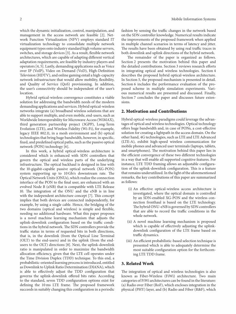
The jitter performance is shown in Figures 13 and 14 forthe first and the second scenarios, respectively. Note thatthese numerical results represent the total average valuesincluding both downlink and uplink streams. The qualityrequirements of jitter imply a latency performance lower than50msec. Both scenarios sustain a safe jitter performance.DIANA succeeds in slightly improving the jitter performancecompared to the static scheme of about 5%. The measuredjitter seems to slightly increase as the number of UEs tends toincrease, sincemore bandwidth requests exist in the network.However, DIANA offers better VoIP performance in total interms of improved latency and slightly improved jitter.
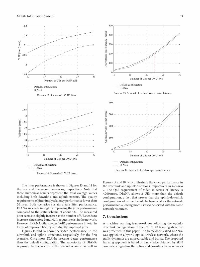
Figures 15 and 16 show the video performance, in thedownlink and uplink directions, respectively, for the firstscenario. Once more DIANA presents better performancethan the default configuration. The superiority of DIANAis proven by the results of the second scenario as well in
10 15 20 25 300
100
200
300
400
500
Number of UEs per ONU-eNB
Dow
nstre
am v
ideo
late
ncy
(mse
c)
Default con�gurationDIANA
Figure 15: Scenario 1: video downstream latency.
10 15 20 25 300
100
200
300
400
Number of UEs per ONU-eNB
Ups
tream
vid
eo la
tenc
y (m
sec)
Default con�gurationDIANA
Figure 16: Scenario 1: video upstream latency.
Figures 17 and 18, which illustrate the video performance inthe downlink and uplink directions, respectively, in scenario2. The QoS requirement of video in terms of latency is<200msec. DIANA allows 2 UEs more than the defaultconfiguration, a fact that proves that the uplink-downlinkconfiguration adjustment could be beneficial for the networkperformance, allowingmore users to be served with the samenetwork resources.
7. Conclusions
A machine learning framework for adjusting the uplink-downlink configuration of the LTE TDD framing structurewas presented in this paper. The framework, called DIANA,was applied in a hybrid optical-wireless network, where thetraffic dynamics are unpredictable and bursty. The proposedlearning approach is based on knowledge obtained by SDNcontrollers regarding the uplink and downlink traffic requests

14 Mobile Information Systems
10 15 20 25 300
100
200
300
400
500
Number of UEs per ONU-eNB
Dow
nstre
am v
ideo
late
ncy
(mse
c)
Default con�gurationDIANA
Figure 17: Scenario 2: video downstream latency.
10 15 20 25 300
1
2
3
4
Number of UEs per ONU-eNB
Ups
tream
vid
eo la
tenc
y (m
sec)
Default con�gurationDIANA
Figure 18: Scenario 2: video upstream latency.
of the mobile end-users. The introduced framework decidesthe most suitable configuration for the forthcoming TDDframe based on the traffic demands of the previous frames.A probabilistic-based approach ensures the accuracy of themethods by promoting configurations that result in bestnetwork performance. The proposed framework was exten-sively assessed using real traffic traces in terms of VoIP,real-time video, and streaming video. Simulation resultsindicate the superiority of the traffic-aware framework inany applied channel and traffic parameters. DIANA demon-strated improvements about 40% in terms of average latency,while it demonstrated notable improvements, about 30%,in VoIP and video latency. Our future plans include theexpansion of this work in a threefold way. First, we intendto investigate the dynamic adjustment of the LTE frame inhybrid networks, where the optical domain consists of multi-channel PONs. Second, we envisage exploring the behaviour
of such hybrid optical-wireless networks by consideringmultiple traffic sources, for example, both mobile end-usersand users connected in the optical interfaces.Third, the long-term dependence and the self-similar characteristics of trafficpresent in access networking will be examined in the light ofimproving the learning process by making it independent ofspeed parameters such as𝑊.
Notations
𝑁: Number of ONU-eNBs𝐶 = {𝑐0, 𝑐1, . . . , 𝑐7}: The set of the uplink-downlink
configuration options𝑅 = {𝑟0, 𝑟1, . . . , 𝑟7}: Downlink-to-uplink ratio in terms of
offered bits𝑟𝑖𝑑(𝑓): Requested bits in the downlink
direction in the 𝑖ONU-eNB at frame 𝑓𝑟𝑖𝑢(𝑓): Requested bits in the uplink direction
in the 𝑖 ONU-eNB at frame 𝑓𝑃𝑖(𝑓): Ratio probability vector at frame 𝑓𝑐𝑖𝑠(𝑓): Feedback in terms of configuration at
frame 𝑓𝑊: Learning speed parameter𝑎: Probability protection parameter.
Conflicts of Interest
The authors declare that there are no conflicts of interestregarding the publication of this paper.
References
[1] E. Wong, “Next-generation broadband access networks andtechnologies,” Journal of Lightwave Technology, vol. 30, no. 4,Article ID 6094146, pp. 597–608, 2012.
[2] A. S. Thyagaturu, A. Mercian, M. P. McGarry, M. Reisslein,andW. Kellerer, “Software DefinedOptical Networks (SDONs):a comprehensive survey,” IEEE Communications Surveys andTutorials, vol. 18, no. 4, pp. 2738–2786, 2016.
[3] O. Gerstel, M. Jinno, A. Lord, and S. J. B. Yoo, “Elasticoptical networking: a new dawn for the optical layer?” IEEECommunications Magazine, vol. 50, no. 2, pp. S12–S20, 2012.
[4] S. Sun, M. Kadoch, L. Gong, and B. Rong, “Integrating net-work function virtualization with SDR and SDN for 4G/5Gnetworks,” IEEE Network, vol. 29, no. 3, pp. 54–59, 2015.
[5] S. Wang, L. Sun, Q. Sun, X. Li, and F. Yang, “Efficient serviceselection in mobile information systems,” Mobile InformationSystems, vol. 2015, Article ID 949436, 10 pages, 2015.
[6] A. G. Sarigiannidis, M. Iloridou, P. Nicopolitidis et al., “Archi-tectures and bandwidth allocation schemes for hybrid wireless-optical networks,” IEEE Communications Surveys and Tutorials,vol. 17, no. 1, pp. 427–468, 2015.
[7] G. Shen, R. S. Tucker, and C.-J. Chae, “Fixed mobile conver-gence architectures for broadband access: Integration of EPONand WiMAX,” IEEE Communications Magazine, vol. 45, no. 8,pp. 44–50, 2007.
[8] N. Chen, S. Sun, M. Kadoch, and B. Rong, “SDN controlledmmwave massive MIMO hybrid precoding for 5G heteroge-neous mobile systems,” Mobile Information Systems, vol. 2016,Article ID 9767065, 10 pages, 2016.

Mobile Information Systems 15
[9] T. Kamisaka, T. Kuri, and K.-I. Kitayama, “Simultaneous mod-ulation and fiber-optic transmission of 10-Gb/s baseband and60-GHz-band radio signals on a single wavelength,” IEEETransactions on Microwave Theory and Techniques, vol. 49, no.10, pp. 2013–2017, 2001.
[10] A. Martinez, V. Polo, and J. Marti, “Simultaneous basebandand RF optical modulation scheme for feeding wireless andwireline heterogeneous access networks,” IEEE Transactions onMicrowaveTheory andTechniques, vol. 49, no. 10, pp. 2018–2024,2001.
[11] J. Wu, Z. Zhang, Y. Hong, and Y. Wen, “Cloud radio accessnetwork (C-RAN): a primer,” IEEE Network, vol. 29, no. 1, pp.35–41, 2015.
[12] S. Sarkar, S. Dixit, and B. Mukherjee, “Hybrid wireless-opticalbroadband-access network (WOBAN): a review of relevantchallenges,” Journal of Lightwave Technology, vol. 25, no. 11, pp.3329–3340, 2007.
[13] A. S. Reaz, V. Ramamurthi, M. Tornatore, and B. Mukherjee,“Cloud-Integrated WOBAN: an offloading-enabled architec-ture for service-oriented access networks,” Computer Networks,vol. 68, pp. 5–19, 2014.
[14] A. Ahmed and A. Shami, “A new bandwidth allocation algo-rithm for EPON-WiMAX hybrid access networks,” in Pro-ceedings of the 53rd IEEE Global Communications Conference(GLOBECOM ’10), USA, December 2010.
[15] M. Giuntini, A. Valenti, F. Matera, and S. Di Bartolo, “Qualityof service management in hybrid optical-LTE access networks,”in Proceedings of the Future Network and Mobile Summit(FutureNetw ’11), June 2011.
[16] W.-T. Shaw, S.-W. Wong, N. Cheng et al., “Hybrid architectureand integrated routing in a scalable optical-wireless accessnetwork,” Journal of Lightwave Technology, vol. 25, no. 11, pp.3443–3451, 2007.
[17] M. A. Ali, G. Ellinas, H. Erkan, A. Hadjiantonis, and R.Dorsinville, “On the vision of complete fixed-mobile conver-gence,” Journal of Lightwave Technology, vol. 28, no. 16, ArticleID 5473119, pp. 2343–2357, 2010.
[18] S. Ou, K. Yang, M. P. Farrera, C. Okonkwo, and K. M. Guild, “Acontrol bridge to automate the convergence of passive opticalnetworks and IEEE 802.16 (WiMAX) wireless networks,” inProceedings of the 5th International Conference on BroadbandCommunications, Networks, and Systems (BROADNETS ’08),pp. 514–521, September 2008.
[19] N. Moradpoor, G. Parr, S. McClean, B. Scotney, and G. Owusu,“Hybrid optical and wireless technology integrations for nextgeneration broadband access networks,” in Proceedings of the12th IFIP/IEEE International Symposium on Integrated NetworkManagement (IM ’11), pp. 1013–1020, May 2011.
[20] N. Sharma, A. Bansal, and P. Garg, “Generalized OSTBC-basedsubcarrier intensity-modulated MIMO optical wireless com-munication system,” International Journal of CommunicationSystems, 2016.
[21] J. Liu, H. Guo, H. Nishiyama, H. Ujikawa, K. Suzuki, and N.Kato, “New perspectives on future smart FiWi networks: scal-ability, reliability, and energy efficiency,” IEEE CommunicationsSurveys and Tutorials, vol. 18, no. 2, pp. 1045–1072, 2016.
[22] A. Panagiotakis, P. Nicopolitidis, G. I. Papadimitriou, and P. G.Sarigiannidis, “Performance Increase for Highly-Loaded RoFAccess Networks,” IEEE Communications Letters, vol. 19, no. 9,pp. 1628–1631, 2015.
[23] P. Sarigiannidis, M. Louta, G. Papadimitriou, I. Moscholios,A. Boucouvalas, and D. Kleftouris, “Alleviating the high prop-agation delays in FiWi networks: a prediction-based DBAscheme for 10G-EPON-WiMAX systems,” in Proceedings of the4th International Workshop on Fiber Optics in Access Networks(FOAN ’15), pp. 45–50, October 2015.
[24] A. Sarigiannidis and P. Nicopolitidis, “Addressing the interde-pendence in providing fair and efficient bandwidth distributionin hybrid optical-wireless networks,” International Journal ofCommunication Systems, vol. 29, no. 10, pp. 1658–1682, 2016.
[25] P. Sarigiannidis, M. Louta, G. Papadimitriou et al., “A meta-heuristic bandwidth allocation scheme for FiWi networks usingAnt Colony Optimization,” in Proceedings of the 22nd IEEESymposium on Communications and Vehicular Technology in theBenelux (SCVT ’15).
[26] D. Hood and E. Trojer, Gigabit-Capable Passive Optical Net-works, John Wiley & Sons, Inc., Hoboken, NJ, USA, 2012.
[27] D. Simeonidou, R. Nejabati, and M. P. Channegowda, “Soft-ware defined optical networks technology and infrastructure:Enabling software-defined optical network operations,” in Pro-ceedings of the Optical Fiber Communication Conference andExposition and the National Fiber Optic Engineers Conference(OFC/NFOEC ’13), March 2013.
[28] Y. Lee and Y. Kim, “A design of 10 Gigabit Capable PassiveOptical Network (XG-PON1) architecture based on SoftwareDefined Network (SDN),” in Proceedings of the InternationalConference on Information Networking (ICOIN ’15), pp. 402–404, January 2015.
[29] D. Bojic, E. Sasaki, N. Cvijetic et al., “Advanced wirelessand optical technologies for small-cell mobile backhaul withdynamic software-defined management,” IEEE Communica-tions Magazine, vol. 51, no. 9, pp. 86–93, 2013.
[30] “3GPP: E-UTRA and E-UTRAN Overall Description, 3GPP,March 2012, v10.7.0”.
[31] F. Capozzi, G. Piro, L. A. Grieco, G. Boggia, and P. Camarda,“Downlink packet scheduling in LTE cellular networks: keydesign issues and a survey,” IEEE Communications Surveys andTutorials, vol. 15, no. 2, pp. 678–700, 2013.
[32] http://www.mathworks.com/.

Submit your manuscripts athttps://www.hindawi.com
Computer Games Technology
International Journal of
Hindawi Publishing Corporationhttp://www.hindawi.com Volume 2014
Hindawi Publishing Corporationhttp://www.hindawi.com Volume 2014
Distributed Sensor Networks
International Journal of
Advances in
FuzzySystems
Hindawi Publishing Corporationhttp://www.hindawi.com
Volume 2014
International Journal of
ReconfigurableComputing
Hindawi Publishing Corporation http://www.hindawi.com Volume 2014
Hindawi Publishing Corporationhttp://www.hindawi.com Volume 201
Applied Computational Intelligence and Soft Computing
Advances in
Artificial Intelligence
Hindawi Publishing Corporationhttp://www.hindawi.com Volume 2014
Advances inSoftware EngineeringHindawi Publishing Corporationhttp://www.hindawi.com Volume 2014
Hindawi Publishing Corporationhttp://www.hindawi.com Volume 2014
Electrical and Computer Engineering
Journal of
Hindawi Publishing Corporation
http://www.hindawi.com Volume 2014
Advances in
Multimedia
International Journal of
Biomedical Imaging
Hindawi Publishing Corporationhttp://www.hindawi.com Volume 2014
Advances in
Hindawi Publishing Corporationhttp://www.hindawi.com Volume 201
RoboticsJournal of
Hindawi Publishing Corporationhttp://www.hindawi.com Volume 2014
Hindawi Publishing Corporationhttp://www.hindawi.com Volume 2014
Computational Intelligence and Neuroscience
Industrial EngineeringJournal of
Hindawi Publishing Corporationhttp://www.hindawi.com Volume 2014
Modelling & Simulation in EngineeringHindawi Publishing Corporation http://www.hindawi.com Volume 2014
The Scientific World JournalHindawi Publishing Corporation http://www.hindawi.com Volume 2014
Hindawi Publishing Corporationhttp://www.hindawi.com Volume 2014
Human-ComputerInteraction
Advances in
Computer EngineeringAdvances in
Hindawi Publishing Corporationhttp://www.hindawi.com Volume 2014