dielectrodynamics and applications - vixravixra.org/pdf/1704.0386v1.pdf · devices or equipments is...
TRANSCRIPT

Page 1 of 41
Dielectrodynamics and applications
Yanming Wei
Kiwaho laboratory of energy and ecology Inc. K0E1S0, Ontario, Canada. Email: [email protected]
Part one
Dielectric blade comb piston mechanic-electric bi-direction converter
First version
Abstract
The electric vs. mechanic bi-directional power conversion application has been
traditionally and asymmetrically favoring at magnetic element as energy caching and
buffering bridge, e.g. the electric motors and generators that are also abstracted as
electromechanical devices. The theory behind those omnipresent electromechanical
devices or equipments is electrodynamics.
Based on recent fast development of high energy density dielectric materials, my
inventions are to be a game changer: let electrical field alone to take the heavy duty of
electromechanical utilities, and let “dielectrodynamics” replace electrodynamics.
Of the most importance is the key limitless high voltage generator, which can cover full
gamut of voltages from volts to kilovolts (KV), megavolts (MV), even gigavolts (GV), and
what we need, is just to provide necessary space occupancy and mechanic work acting
on dielectric blade comb-like piston. Either motor or generator can be re-invented with
this core dielectrodynamic module.
Page 2 of 41
Table of Contents
§1. Introduction ......................................................................................................................... 3
§2. Background of pertinent technologies ................................................................................ 3
§3. Why is magnetism-involved high voltage system bottlenecked about MV-level? ............. 6
§4. Energy density (ED) matters. ............................................................................................... 6
§5. Reciprocal converter of mechanical to electrostatic energy ............................................... 8
§6. Work stroke analysis ......................................................................................................... 11
§7. Reset stroke analysis ......................................................................................................... 13
§8. Rotary converter of mechanical to electrostatic energy ................................................... 16
§9. Geometry consideration .................................................................................................... 18
§10. Special driving mechanism for dense insertion of intermediate plates ............................ 20
§11. What if one dielectric medium is liquid? ........................................................................... 21
§12. Why pulse output and how to control pulse width? ......................................................... 22
§13. Design exercise .................................................................................................................. 24
§14. Is generator-motor double-duty possible with a device based on this invention? .......... 27
§15. Is dielectric displacement generator equal to triboelectric generator? ........................... 28
§16. Conclusion and the profound influence to future technology .......................................... 28
§17. Application in high energy physics Z-pinch experiment .................................................... 29
§18. Application in general high voltage periodic pulse generator .......................................... 31
§19. Application in utility grade dielectric motor...................................................................... 33
§20. Application in mobile medical X-ray source ...................................................................... 35
§21. Application in new type propeller of ornithopter aircraft ................................................ 38
§22. Reference literature .......................................................................................................... 41

Page 3 of 41
§1. Introduction
The electric vs. mechanic bi-directional power conversion application has been
traditionally and asymmetrically favoring at magnetic element as energy caching and
buffering bridge, e.g. the electric motors and generators that are also abstracted as
electromechanical devices, and the backing theory is electrodynamics.
Based on the fast development of high energy density dielectric materials, it is the high
time to change the game: let electrical field alone to take the heavy duty of
electromechanical utilities, and let “dielectrodynamics” replace electrodynamics.
Of the most importance is the limitless high voltage generator, which can cover full
gamut of voltages from volts to kilovolts (KV), megavolts (MV), even gigavolts (GV), as
long as necessary space occupancy and mechanic work are secured to assist dielectric
piston or blades displacement.
As the nature of such an electric power supply, it is fit for pulse application, such as Z-
pinch, particle accelerator, nuclear ignition, fusion reactor, ornithopter etc. Civil
application is also possible, such as harvest wind power, pulse heating, electric drive,
but regular non-pulse application may need further power smoothing or conversion.
§2. Background of pertinent technologies
The order of magnitude of voltage matters.
The current best choice of HV (High Voltage) supply, such as Marx generator, Van de
Graaff generator, Tesla coil, the magnitude therein is mostly a few of MVs, none can
march into the GV (gigavolt) domain, even nor most natural lightning.
It is reported that regular lightning can reach 100MV and rarely 1GV; and so far, the
man-made highest voltage record is still hold by the Oak Ridge National Laboratory’s
landmark tandem electrostatic accelerator: 32MV.
Although Marx generator no voltage limit in theory and no magnetic involvement,
Page 4 of 41
however it suffers from low efficiency in recharge and discharge, as worse as too many
discrete high voltage capacitors occupying too much space, so as hopeless to achieve
arbitrary high voltage.
Van de Graaff generators are of electrostatic type, and its ability of voltage anteing up is
also frustrated by some factors, though it was the high voltage record keeper.
Tesla coil can also generate MV-level high AC (alternating current) voltage, however
almost all super voltage applications are only in favor of DC (direct current), e.g. particle
accelerator, unfortunately high voltage rated rectifier diodes are so few or expensive.
The scientific community is now focusing at the research of LTD (Linear Transformer
Driver) high voltage (MV-level) and pulse high current (MA-level) generating technology,
for example, the Sandia National Laboratory for her next Z-machine power supply.
As the LTD voltage adders need magnetic involvement in generation of huge power
pulse, so it is doomed to face the cumbersome volume and expensive investment,
perhaps more other technical difficulties, such as the unavoidable high parasitic
inductance prohibiting the pulse width narrowing, etc.
Although the GeV and TeV accelerator can be built, however, a single DC power supply
can never cope with it, instead of cascade RF powered LINAC, as well as the huge cost
may be almost a financial black hole.
In the adventure of fusion, the magnetic inertial confinement Tokomak solution still
struggles for the sustaining time and energy breakeven balance.
And almost all electromechanical devices, such as electric motors, generators, etc., still
need the co-operation or interaction between the inherent electric fields and the
induced or permanent magnetic fields.
If we can economically access GV-level or above electricity, or even if we can make mid-
range voltage utilities but with light weight feature resulted by elimination of expensive
rare earth magnetic materials and heavy copper coils, then a new world will emerge,
especially both the fusion new epoch and the magnetic-free revolution of

Page 5 of 41
electromechanical equipments will loom and boom.
Motivated by such a great cause, my exploration is aiming at seeking feasible voltage-
transforming methods to get rid of magnetic involvement and to break the prior record
of high voltage as extensive as possible.
The shared play stage of electric and magnetic fields are now going to be monopolized
by electric field only, can such a fresh electromechanical device or transformer still
function as usual?
Yes, it can! After following brief introduction, I will show how to realize it in detail soon.
As electric energy can be stored either in pure electric field, or in pure magnetic field, or
in hybrid of electric and magnetic fields, so even no longer available for the regular
mode of electric and magnetic fields interplay together, the pristine electric-field-only
device can still deal with energy transaction in circuit.
Intuitively dielectric-conditioned capacitors can cache electric energy or conduct energy
transaction via discharge, and those behaviors and actions can be completed in pure
electric field only without magnetic involvement, though dielectric media are insulators.
So in brief, it is proved true that dielectric materials can play the electric-field-only
monologue in any utility application.
Now the only leftover concern is that whether the electric-field-only apparatus can be
as powerful as the regular electric plus magnetic hybrid-field apparatus.
This concern will be thawed by the good news: in 2010, the Pennsylvania state
university invented a new dielectric material which energy density is the top-rated and
surpasses far more over the top affordable magnetic energy density. The publication of
“DIELECTRIC BREAKDOWN OF ALKALI-FREE BOROALUMINOSILICATE GLASS THIN FILMS”
heralds its coming.
Page 6 of 41
§3. Why is magnetism-involved high voltage system bottlenecked about MV-level?
Magnetism-involved transformers always run on inductive effect where electromagnetic
oscillation occurs, and oscillation results in AC in circuit, but for the extreme high
voltage application, the DC is always preferred, so rectification should be done.
Diodes are applied for the purpose of rectification, and most diodes are made of
semiconductors, the others vacuum tubes. As unidirectional passage electric component,
a diode should withstand reverse voltage. For low voltage applications, never worry
about it, but for extreme high voltage over specific threshold, reverse breakdown failure
becomes a serious problem.
Diodes seem impossible or extremely difficult to withstand extreme high voltage larger
than million volts. That is why the Tesla coil high voltage generator rarely used in
particle accelerator, and that is also why the doomed bottleneck does exist for all
magnetism-involved high voltage generator.
Of course, the dielectrodynamic based magnetism-free high voltage generator has no
such a bottleneck.
§4. Energy density (ED) matters.
For the industry-favored magnetic energy, the ED can be calculated via formula B2/(2μ),
where B stands for magnetic strength, and μ permeability, 4π*10-7H/m for vacuum
space. For the economic choice of max accessible B, e.g. B = 2 Tesla, we have ED =
1.6*106 J/m3 = 1.6MJ/m3.
For the dielectric space, the ED = ϵϵ0E2/2, where E stands for electric field strength, ϵ0 =
vacuum permittivity = 8.85*10-12F/m, ϵ = relative dielectric constant to vacuum or air.
If taking E = 3MV/m as the breakdown limit of the regular atmosphere space, we can
only get 40J/m3, of course it is extreme shy to compare with magnetism.
But nowadays we have more and more better choices of dielectric materials to cache

Page 7 of 41
and buffer energy, even water is not too bad choice if its other demerit could be
overcome, because of its high ϵ = 80 and high breakdown electric field E = 60MV/m,
then ED = 1.3MJ/m3, on par with the aforementioned magnetic ED.
Other excellent dielectric materials: piezoelectric ceramic, ED = 16MJ/m3; AF45,
invented by Pennsylvania university, ED = 38.5MJ/m3. Specially, AF45 is described by
media ScienceDaily News as “Storing A Lightning Bolt In Glass For Portable Power”,
because its breakdown limit can reach the incredible 1.2GV/m!
In fact, energy density also reflects the specific pressure. This can be validated by
checking the dimension in SI unit: J/m3 = Nm/m3 = N/m2 = Pa, J -- Joule, m -- meter, N –
Newton (1kg = 9.8N), Pa -- Pascal.
The western favored pressure unit are bar and psi (pound per square inch), and 0.1MPa
= 1bar = 14.5psi. So the abovementioned magnetic energy density is also the magnetic
pressure 1.6MPa = 16bar = 232psi, as well as the air 40Pa = 0.0058psi, the AF45 electric
pressure 38.5MPa = 385bar = 5582psi. As a common sense, car tire is about 30psi, and
commercial hydraulic system about 2000psi, hence we see the AF45 electric pressure is
even more powerful than a crane’s hydraulic system.
No wonder almost all electric power systems utilize magnetism, because its decent
pressure 232psi sounds strong enough for general dynamic applications, despite only
about 10% strength of hydraulic system!
Now that the new generation of dielectric materials possesses such a high electric
pressure up to 5582psi ≫ regular magnetic pressure 232psi, why to hesitate to utilize
them? The answer is because the current industry is not adept to make use of the
electrostatic force.
My research shows that mechanical work can be efficiently converted to electrostatic
energy with very little loss.

Page 8 of 41
§5. Reciprocal converter of mechanical to electrostatic energy
Firstly, let us review the capacitor’s capacitance and its energy storage.
For the simple parallel-plate capacitor, its capacitance C = ϵ ϵ0A/d where A -- the plate’s
area, d -- the distance of plates, and its total stored energy = Volume*ϵϵ0E2/2.
As the energy is proportional to square of electric field E, but linear with ϵ, and E = V/d,
V --voltage, so increasing V for higher energy density is more sensitive than increasing ϵ.
By changing ϵ or E or volume, we can change the stored energy, but no way to alter
material dielectric breakdown strength because of Emax always limited, except simply
changing the voltage configuration under allowable Emax.
Changing ϵ can be done by mechanical displacement or temperature.
But the thermoelectric efficiency is quite low because of its high entropy, mostly < 2%,
even the most excellent mineral tetrahedrite < 7%, so just forget temperature method.
Mechanic energy is low entropy and can be high efficiently converted to electric energy.
Luckily, we have a great range of ϵ to select; the highest ϵ even may hit the value of
about 1010, e.g. the special formulated electrolyte materials in super capacitors, though
their rated voltage is low.
Nowadays low cost high ϵ between 1000 and 100000 are used everywhere, such as the
piezoelectric material in the cheap cigarette lighter. The regular high voltage rated solid
material, e.g. PbMgNO3 + PbTiO3, its high ϵ = 22600.
The easy mechanic energy carrier or transmitter is piston, however no necessary to be
the traditional cylindrical shape, in my dielectric media displacement inventions, the
best shape of dielectric piston is thin slices or blades with rectangular or rotary
transverse section.
By input mechanical work, we can change, or say, displace different materials inside the
capacitor with great ϵ change. As per energy conversation law, we have equation:
Initial stored energy (state 1, Volume*ϵ1ϵ0E2/2) + Mechanic energy =
Page 9 of 41
Final stored energy (state 2, Volume*ϵ2ϵ0E2/2) + Friction loss.
It means the incipient medium with dielectric constant ϵ1 is displaced by medium ϵ2.
For simplification, we can omit the negligible friction loss, as friction reduction
engineering methods are always available to choose and apply.
We do need initial energy pre-stored in the capacitor. If not, the dielectric material will
be not pinched by any electrostatic force, so no way to absorb mechanic work for a
loose free dielectric medium.
The initial energy is provide by initial electric field or exciting voltage, in mimic of
electric motor or generator jargon where exciting current is needed to initialize
magnetic field if no permanent magnet is used.
We do not demand too much initial energy from the said exciting voltage, just like a
motor or generator usually draws small fractional basic current for keeping basic
exciting magnetic field.
Of course, special permanent electret material can be used, so no need to input it with
initial energy, instead of collecting charges from free space, but hopeless of heavy duty.
For maximal mechanic energy harvest, we wish the final stored energy is far more than
initial stored energy.
Usually, the higher the ϵ, the higher polarization rate of bipolar moments, then more
charges will be locked on the plates. Only by displacing higher ϵ2 medium with lower ϵ1
medium, then there are more unlocked free charges accumulated with potential to
push to higher voltage, though the total locked and unlocked charges are conservative.
The higher the voltage increase, the more tightly the plates are pinched, then the more
mechanic work you have to input, otherwise the medium is loose and free to move.
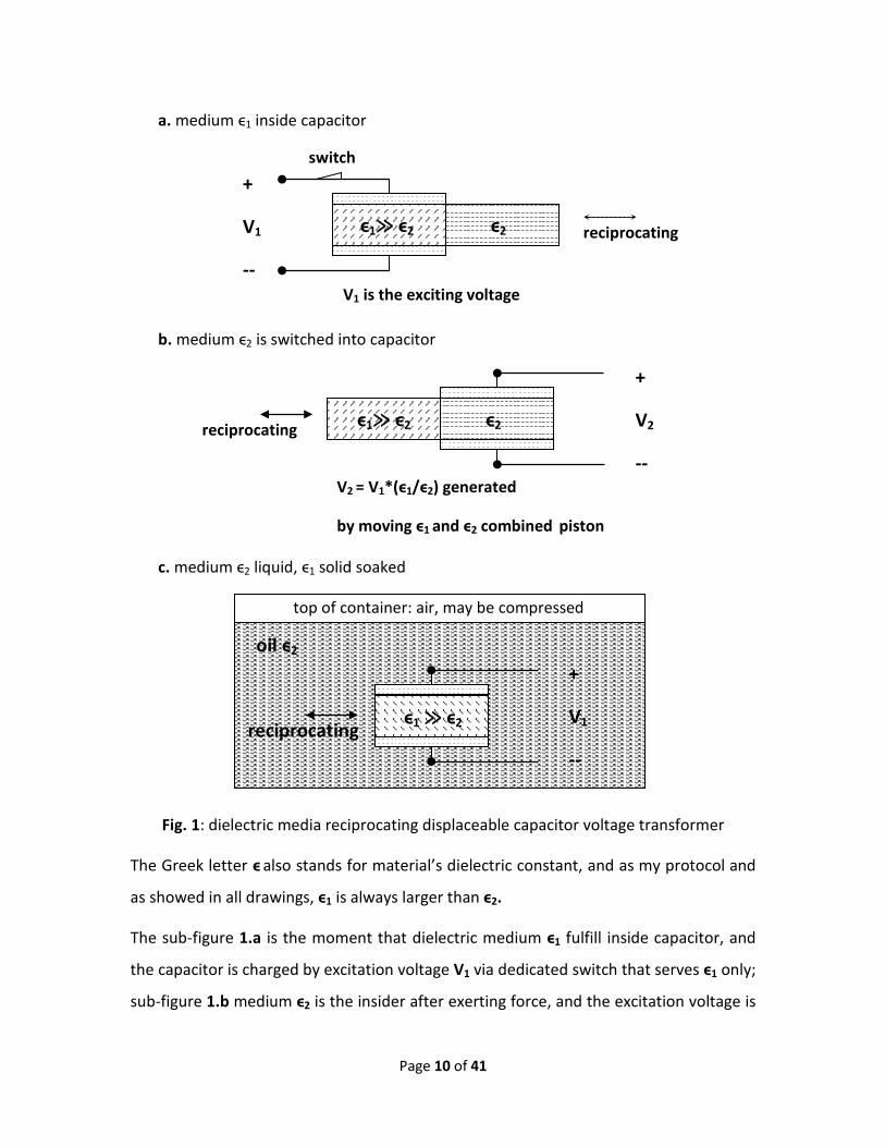
Fig. 1 shows an abstract dielectric media reciprocally displaceable capacitor with
mechanical input and voltage output. The electrode plates are like as “stators”, and 2
joined dielectric materials play lively as a laminating board “piston”. Both stators and
pistons are in shape of rectangle.
Page 10 of 41
Fig. 1: dielectric media reciprocating displaceable capacitor voltage transformer
The Greek letter ϵ also stands for material’s dielectric constant, and as my protocol and
as showed in all drawings, ϵ1 is always larger than ϵ2.
The sub-figure 1.a is the moment that dielectric medium ϵ1 fulfill inside capacitor, and
the capacitor is charged by excitation voltage V1 via dedicated switch that serves ϵ1 only;
sub-figure 1.b medium ϵ2 is the insider after exerting force, and the excitation voltage is
ϵ1≫ ϵ2 ϵ2
reciprocating
+
V1
-- V1 is the exciting voltage
ϵ2
reciprocating
+
V2
-- V2 = V1*(ϵ1/ϵ2) generated
by moving ϵ1 and ϵ2 combined piston
ϵ1≫ ϵ2
switch
ϵ1 ≫ ϵ2
+
V1
--
oil ϵ2
reciprocating
a. medium ϵ1 inside capacitor
b. medium ϵ2 is switched into capacitor
c. medium ϵ2 liquid, ϵ1 solid soaked
top of container: air, may be compressed
Page 11 of 41
amplified by ϵ1/ϵ2 times; sub-figure 1.c medium ϵ2 is liquid, ϵ1 solid, and whole capacitor
is soaked under oil in a commeasurable container.
Although alternative setting possible: dielectric combination immoveable & electrodes
movable, anyway such is not convenient, as electrodes are often hooked with wires.
§6. Work stroke analysis
So much for the qualitative description, now I quantitatively find how high the voltage
can increase, and how many mechanic work is converted to electrostatic energy after
displacement event, aka “work stroke” in mimic of internal combustion engine jargon.
As total charges conserve during displacement, and constant plate area, plate distance,
volume, so does charge density CD, that means CD = ϵ1ϵ0E1 = ϵ2ϵ0E2, E1 = V1/d, E2 = V2/d -
- electric field strengths of initial and final respectively, V1, V2 -- voltage of initial and
final respectively.
Then we deduce that: V2 = (ϵ1/ϵ2)*V1. For a reasonable design, ϵ1 ≫ ϵ2, hence V2 ≫ V1.
For convenience, hereafter, ϵ1 is always used to stand for high permittivity dielectric
medium, and ϵ2 for low one, even this protocol is also applied universally in all figures.
As to the capacitance, C1 = ϵ1ϵ0A/d, C2 = ϵ2ϵ0A/d, so C2 = (ϵ2/ϵ1)*C1, thus C2 ≪ C1.
According to the formula of total energy of capacitor: the_final_energy = (C2 V22)/2 =
(ϵ2/ϵ1)*C1*[(ϵ1/ϵ2)*V1]2 /2 = (ϵ1/ϵ2)* (C1 V12)/2 = (ϵ1/ϵ2)*the_initial_energy.
Obviously, it is just what we expect: the_final_energy ≫ the_initial_energy.
Assuming friction is zero, hence we have to input mechanic work:
[(ϵ1/ϵ2) – 1]*the_initial_energy to cover the electrostatic energy increase. As ϵ1/ϵ2 ≫ 1,
then [(ϵ1/ϵ2) – 1]*the_initial_energy ≈ (ϵ1/ϵ2)*the_initial_energy = the_final_energy,
i.e., the final stored electrostatic energy is almost the total contributed mechanic work,
and the initial energy, aka “exciting energy”, is just a small token or trigger!
Further, we can calculate the average force to drag the dielectric media.

Page 12 of 41
Assume the capacitor is in shape of rectangle of width W and length L, to completely
displace the initial medium ϵ1 along the length-wise, the mechanism should be exerted
the average force:
F = [(ϵ1/ϵ2) – 1]*the_initial_energy/L
Now, we understand that the higher ϵ1 medium is set to work under low voltage for
exciting initial electrostatic field, and the lower ϵ2 medium as the energy real bearer
working under high voltage, and then we also understand that only the low ϵ2 medium’s
maximum energy density is utilized, but the capability of high ϵ1 medium’s energy
density is under-employed because of its purpose of initial excitation electric field with
small token energy.
One may be interested in the transition of displacement. Now, let’s deal with it.
We use χ to stand for the percentage of transition completeness, and then value 1 or
100% means medium ϵ1 is totally displaced by ϵ2. Hence, the transient voltage,
capacitance, and accumulated energy all are the functions of the parameter χ.
So long as we recognize charge conserve restriction, following functions can be obtained:
The transient capacitance function: C(χ) = C1*[ϵ1(1- χ) + ϵ2 χ]/ϵ1
The transient voltage function: V(χ) = V1*ϵ1/[ ϵ1(1- χ) + ϵ2 χ]
The transient energy function:
the_transient_energy(χ) = the_initial_energy*ϵ1/[ ϵ1(1- χ) + ϵ2 χ]
Substituting χ = 1, we get the same results of the final state with the earlier expressions.
If drawing the respective function graphs, we can find: only capacitance is linear
function, the voltage and energy are both non-linear with very steep curve while χ
approaching 100%. That means no big force is needed during incipient displacement
action, but strong force nearby ending.
Fig. 2 shows the waveform of full loaded voltage output. It hints that the voltage change
between the capacitor electrodes is nonlinearly related with dielectric displacement.

Page 13 of 41
Fig. 2: full loaded voltage output
In brief, when dielectric medium in capacitor is switched from high permittivity ϵ1 to low
one ϵ2, such a displacement needs input of mechanic energy, and in turn this mechanic
energy will be converted to electrostatic energy, thus voltage will be multiplied greatly
by ϵ1/ ϵ2 , in spite that no charging current follow is infused to the capacitor.
§7. Reset stroke analysis
For a utility, it needs to work cycle by cycle constantly. So when the “work stroke”
finished, we see the high voltage, and then need re-start the next cycle.
I define: the reset stroke is referred to the “reverse” displacement that high dielectric
constant medium re-enters the capacitor after the low one goes out of the capacitor.
Obviously if the high voltage energy is not taken away, or say, consumed elsewhere,
then no need to re-input mechanic energy for reset of dielectric medium ϵ1, because the
powerful resilient force will act, and the media combination strip will be accelerated
backwards, that means the stored electrostatic energy will be reversed to mechanic
0 T0 2T0 3T0 4T0
V1
(ϵ1/ϵ2)V1
Output when powering load, unit in V1, assuming ϵ1 ≫ ϵ2, free reset stroke.
V1 = exciting voltage, T0 = cycle period time
Pulse discharge to load
Page 14 of 41
energy, and it may be not what we desired.
If the generated electric energy is not used, then the reset max velocity Ve of the media
movement can be resolved via energy conservation law:
0.5*m*Ve*Ve = the_initial_energy*[(ϵ1/ϵ2) -1], m -- the mass of the dielectric blades.
Ve = {2*the_initial_energy*[(ϵ1/ϵ2) -1]/m }0.5
By gentle holding back media reset, and let media slowly finish the reset stroke in small
constant velocity, then we can prevent the media from gaining significant kinetic energy,
but it will result in higher voltage: V1 (ϵ1/ϵ2)0.5, here V1 is the original exciting voltage.
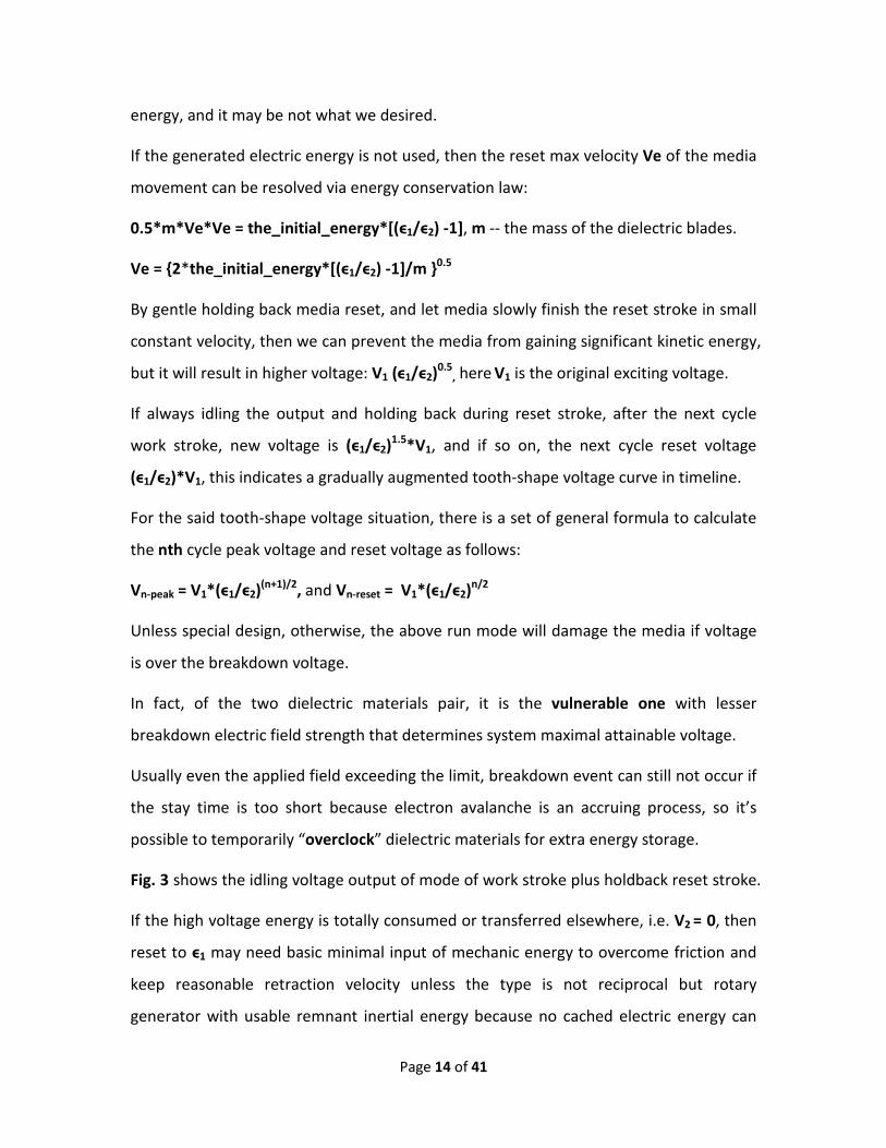
If always idling the output and holding back during reset stroke, after the next cycle
work stroke, new voltage is (ϵ1/ϵ2)1.5*V1, and if so on, the next cycle reset voltage
(ϵ1/ϵ2)*V1, this indicates a gradually augmented tooth-shape voltage curve in timeline.
For the said tooth-shape voltage situation, there is a set of general formula to calculate
the nth cycle peak voltage and reset voltage as follows:
Vn-peak = V1*(ϵ1/ϵ2)(n+1)/2, and Vn-reset = V1*(ϵ1/ϵ2)n/2
Unless special design, otherwise, the above run mode will damage the media if voltage
is over the breakdown voltage.
In fact, of the two dielectric materials pair, it is the vulnerable one with lesser
breakdown electric field strength that determines system maximal attainable voltage.
Usually even the applied field exceeding the limit, breakdown event can still not occur if
the stay time is too short because electron avalanche is an accruing process, so it’s
possible to temporarily “overclock” dielectric materials for extra energy storage.
Fig. 3 shows the idling voltage output of mode of work stroke plus holdback reset stroke.
If the high voltage energy is totally consumed or transferred elsewhere, i.e. V2 = 0, then
reset to ϵ1 may need basic minimal input of mechanic energy to overcome friction and
keep reasonable retraction velocity unless the type is not reciprocal but rotary
generator with usable remnant inertial energy because no cached electric energy can

Page 15 of 41
assist, but the token electric field should be regenerated by low exciting voltage for the
next cycle to run.
Fig. 3: idling voltage output of mode of work stroke plus holdback reset stroke
However we can take accurate control to the output high voltage discharge in order to
omit the tedious re-excitation or possible minimal mechanic energy input, it means that
only one time is necessary to excite initial field during uptime. In this case the post-
discharge remaining voltage should keep the remaining energy equal to the initial
excitation energy:
Volume*ϵ1ϵ0E12/2 = Volume*ϵ2ϵ0Eremain
2/2
i.e. Vremain = V1*( ϵ1/ ϵ2)0.5
If the remaining voltage is less than the Vremain, it is necessary to partially recharge the
initial voltage to the same V1, if every cycle needs same performance.
In fact, the initial energy just a small token, re-exciting is not a big deal, so never mind to
fully discharge the high voltage output if accurate control is difficult.
If partial output consumption does occur but the leftover voltage is still greater than
0 T0 2T0 3T0 4T0
Assuming ϵ1/ϵ2 = 2, V1 = 12V – exciting voltage
Running mode: work stroke + holdback reset stroke
T0 = cycle period time
V1
2V1
3V1
4V1
5V1
6V1
7V1
8V1
Idling output, unit in V1
Dotted lines show the input/output window if media over-cover electrodes

Page 16 of 41
Vremain, perhaps it is a good idea to directly dump the remained small energy until Vremain
is seen (or 0 if not care about re-excitation) by simply short connecting the positive and
negative terminals for smooth reset.
By comparison, the conventional electromechanical device even eats more mechanic
energy by the inevitable magnetic material eddy current heating.
The most spectacular output energy take-away method may be the Z-pinch discharge;
at least, that is the preferred choice for Sandia National Lab.
From above studying, we can conclude that the high voltage output is limitless, GV
(Gagavolt), TV (Teravolt), even PV (Petavolt) are never a dream, provided only the
dielectric breakdown strength Emax should be respected, because V = Emax*d and the
parameter of distance d unlimited, as long as space is not restrained, such as in km level.
§8. Rotary converter of mechanical to electrostatic energy
As rectangle configuration is good only for reciprocal displacement, but if rotary motion
is preferred, then circle configuration is needed.
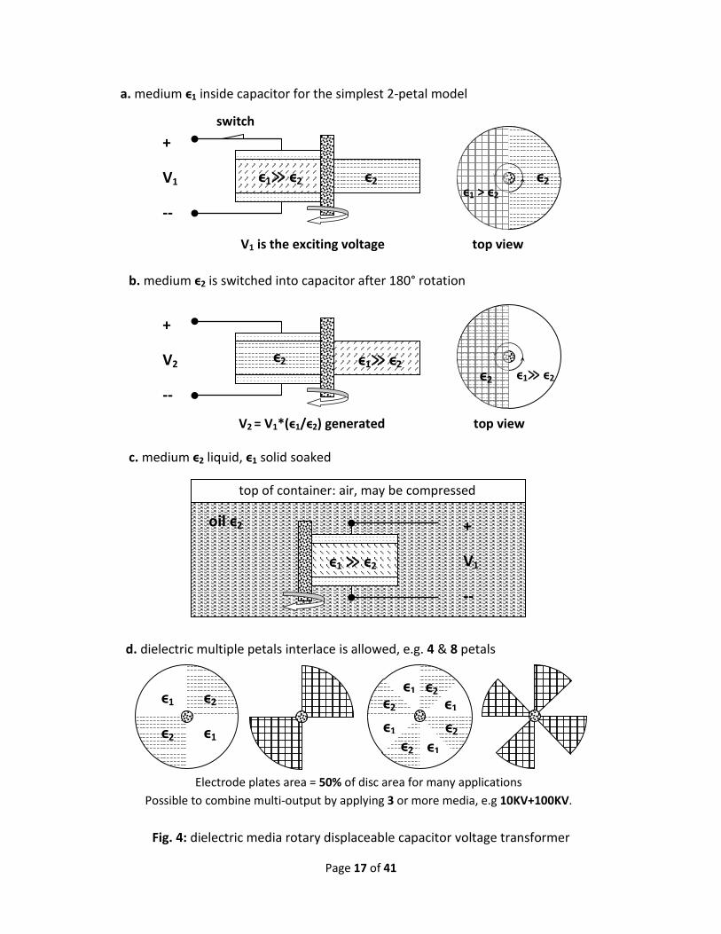
Fig. 4 shows some variants of rotary displaceable capacitor mechanic-voltage
transformer. Similar to fig. 1, instead of laminating board piston, the moving parts
change to rotatable laminating disk, and instead of pull or push, rotating torque is
exerted via shaft.
For 2-patal laminating disk, the electrode plates are semicircle disks.
Sub-figure 4.a shows the moment that medium ϵ1 is lodging inside capacitor and
charged by voltage exciter that serves ϵ1 only.
Sub-figure 4.b shows medium ϵ2 is switched into capacitor after 180° rotation, and
capacitor output voltage is enlarged to V1*( ϵ1/ϵ2).
In sub-figure 4.c, medium ϵ2 is liquid, ϵ1 solid, and whole capacitor is soaked under oil in
a commeasurable container. In this case, the rotor is a semicircle disk with shaft.
Page 17 of 41
Fig. 4: dielectric media rotary displaceable capacitor voltage transformer
V2 = V1*(ϵ1/ϵ2) generated top view
ϵ1 ≫ ϵ2
+
V1
--
oil ϵ2
a. medium ϵ1 inside capacitor for the simplest 2-petal model
b. medium ϵ2 is switched into capacitor after 180° rotation
c. medium ϵ2 liquid, ϵ1 solid soaked
top of container: air, may be compressed
ϵ1≫ ϵ2 ϵ2
+
V1
--
V1 is the exciting voltage top view
switch
ϵ2 ϵ1≫ ϵ2
+
V2
-- ϵ1≫ ϵ2
d. dielectric multiple petals interlace is allowed, e.g. 4 & 8 petals
ϵ1 ϵ2
ϵ2 ϵ1 ϵ2
ϵ1
ϵ1
ϵ1
ϵ1
ϵ2
ϵ2
ϵ2
Electrode plates area = 50% of disc area for many applications Possible to combine multi-output by applying 3 or more media, e.g 10KV+100KV.
ϵ2
ϵ1 > ϵ2
ϵ2
Page 18 of 41
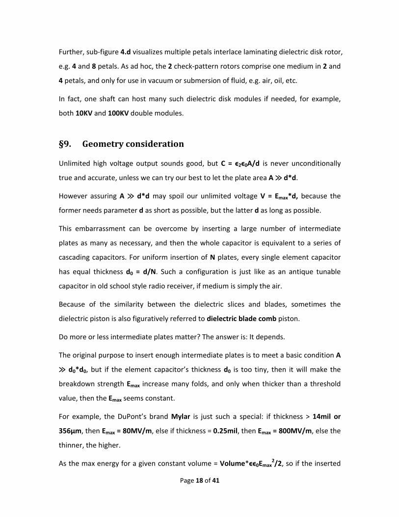
Further, sub-figure 4.d visualizes multiple petals interlace laminating dielectric disk rotor,
e.g. 4 and 8 petals. As ad hoc, the 2 check-pattern rotors comprise one medium in 2 and
4 petals, and only for use in vacuum or submersion of fluid, e.g. air, oil, etc.
In fact, one shaft can host many such dielectric disk modules if needed, for example,
both 10KV and 100KV double modules.
§9. Geometry consideration
Unlimited high voltage output sounds good, but C = ϵ2ϵ0A/d is never unconditionally
true and accurate, unless we can try our best to let the plate area A ≫ d*d.
However assuring A ≫ d*d may spoil our unlimited voltage V = Emax*d, because the
former needs parameter d as short as possible, but the latter d as long as possible.
This embarrassment can be overcome by inserting a large number of intermediate
plates as many as necessary, and then the whole capacitor is equivalent to a series of
cascading capacitors. For uniform insertion of N plates, every single element capacitor
has equal thickness d0 = d/N. Such a configuration is just like as an antique tunable
capacitor in old school style radio receiver, if medium is simply the air.
Because of the similarity between the dielectric slices and blades, sometimes the
dielectric piston is also figuratively referred to dielectric blade comb piston.
Do more or less intermediate plates matter? The answer is: It depends.
The original purpose to insert enough intermediate plates is to meet a basic condition A
≫ d0*d0, but if the element capacitor’s thickness d0 is too tiny, then it will make the
breakdown strength Emax increase many folds, and only when thicker than a threshold
value, then the Emax seems constant.
For example, the DuPont’s brand Mylar is just such a special: if thickness > 14mil or
356μm, then Emax = 80MV/m, else if thickness = 0.25mil, then Emax = 800MV/m, else the
thinner, the higher.
As the max energy for a given constant volume = Volume*ϵϵ0Emax2/2, so if the inserted

Page 19 of 41
number N is reasonable, then the energy capacity has nothing to do with insertion
number N, else if too dense the energy capacity will be multiplied because Emax will
increase if spacing very short.
Fig. 5: too thick capacitor’s main plates inserted with many intermediates
While the count N of intermediate media blades are inserted, to separate dielectric
blades, the same insertion count of intermediate electrode plates are also needed.
a. cascade mode, total capacitance = embedded_capacitance/(N+1)
ϵ1≫ ϵ2 ϵ2
Reciprocating jointly
ϵ1≫ ϵ2 ϵ2
ϵ1≫ ϵ2 ϵ2
ϵ1≫ ϵ2 ϵ2
ϵ1≫ ϵ2 ϵ2
ϵ1≫ ϵ2 ϵ2
Reciprocating jointly
ϵ1≫ ϵ2 ϵ2
ϵ1≫ ϵ2 ϵ2
ϵ1≫ ϵ2 ϵ2
ϵ1≫ ϵ2 ϵ2
Inserted plates M
ain plates
capacitor lead 2
capacitor lead 1
b. parallel mode, total capacitance = embedded_capacitance*(N+1)
capacitor lead 1
capacitor lead 2

Page 20 of 41
There are many tactics of wiring the inserted electrode plates, such as parallel mode,
cascade mode, or mix mode.
Above fig. 5 sketchingly teaches how to stuff thick capacitor with many very thin
dielectric laminating blades, and combine all blades into a drivable comb.
It is just a sample with N = 4 plates inserted between 2 main plates, in fact, N can be as
many as necessary to assure plate area ≫ (neighboring plate distance)2, as long as both
economics and performance factors are considered.
When extreme high voltage is pursued, it is preferred to wire in cascade mode that
nothing wiring job is required really. In this case, the whole capacitance equals the
embedded cell capacitor’s capacitance divided by total cell number, i.e. Cgrand = Ccell/N,
the mode illustration can be seen in sub-fig. 5a: cascade mode.
When higher current is pursued, it is preferred to wire in parallel mode that every other
one electrode plate is connected together. In this case, the whole capacitance equals
the embedded cell capacitor’s capacitance multiplied by total cell number, i.e. Cgrand =
Ccell*N, the mode illustration can be seen in sub-fig. 5b: parallel mode.
As to the mix mode that can just be the simple mix of cascade and parallel mode, most
likely it is for midrange voltage goal.
Although the deployment of tiny thickness element capacitors can increase the energy
density, the mechanic strength of every individual media combination slice may be
deteriorated, especially, the thinner the material, the greater intolerable deformation
under stretch stress and the quicker increase of undesired friction, so careful trade-off
should be considered.
§10. Special driving mechanism for dense insertion of intermediate plates
As to how to drag-out or push-in the combination dielectric strips or slabs or blades, it is
not a scientific issue, but a technical or engineering issue.
Page 21 of 41
Assuming the two dielectric media both solid, we can joint adjacently the media of same
size on a common substrate strip, and then make the strip drivable, but the affect of
substrate should be considered.
For N-plate inserted system, all parallel media-carrier strips should be joined together to
a rigid lead bar, and then total driving force is distributed to dielectric pieces uniformly.
As the speed of work stroke does not matter, we can use gear system or winch or
whatever fast or slow means to drive the displacement for better torque or force match.
For example, the high voltage system can either be hand-powered via winch, or wind-
power, or regular electric motor, or fuel engine.
For Z-pinch application, we wish the discharge pulse as narrow as possible, however it
has no relation to the accumulation speed of high voltage. That is why multiple
mechanic drive still allowed. Only for applications of high ratio of duty cycle, e.g. fusion
reactor, we need speed the mechanic driving response time.
For friction reduction, all metal plates and media surface should be polished as mirrors.
Some dielectric media are innately low friction, e.g. Teflon (Polytetrafluoroethylene),
just consider it if its dielectric properties meet design requirements.
§11. What if one dielectric medium is liquid?
Solid dielectric media are never the exclusive choice, but at least one of the pair media
should be solid for convenience of drive and separation of media.
When one of the media is liquid, the partner medium is better to be soaked inside to
take advantage of gravity or hydraulic pressure induced automatic displacement.
Some liquid dielectric media have high breakdown strength and decent ϵ, e.g.
transformer oil: ϵ = 4.5, Emax > 110MV/m, specific weight 900Kg/m3, also good thermal
conductivity and arc quenching ability, so just choose it if possible.
There are some special phenomena with liquid media: bubble and cavitation. It is better
to avoid the occurrence because dielectric properties will be changed if too many
Page 22 of 41
embedded bubbles, also the cavitation is harmful and can corrode mechanic parts,
despite that cavitation may induce nuclear fusion too, anyway not significant.
Not only liquid, but also gas phase can be considered if it can feature high breakdown
electric field strength. Unfortunately all gas media have lower breakdown strength
compared with solid and liquid.
§12. Why pulse output and how to control pulse width?
During increase of voltage, i.e. switching from high dielectric permittivity to low one,
any load will be “toxic”, because the load will draw electric current, and then depress
the accruement of voltage, also cap the absorption of mechanic energy; only therein
idling can maximize the energy conversion from mechanic to electric.
Thus, there should be a switch to disconnect the load from the capacitor while in action
of displacement, and then reconnect during phase of “rest stay” aka “step stay” while
same medium is U-turning or arc-sweeping inside the margin which width equals to the
difference value between the medium and electrode plates, as illustrated in the fig. 6.
As powering load during voltage accumulation will dampen the max accessible voltage,
so an application based on such component is most preferred to be used in pulse mode.
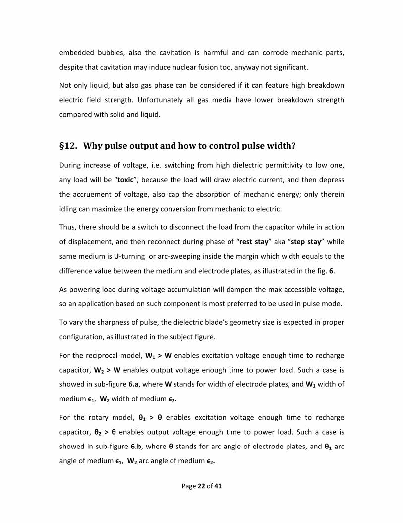
To vary the sharpness of pulse, the dielectric blade’s geometry size is expected in proper
configuration, as illustrated in the subject figure.
For the reciprocal model, W1 > W enables excitation voltage enough time to recharge
capacitor, W2 > W enables output voltage enough time to power load. Such a case is
showed in sub-figure 6.a, where W stands for width of electrode plates, and W1 width of
medium ϵ1, W2 width of medium ϵ2.
For the rotary model, θ1 > θ enables excitation voltage enough time to recharge
capacitor, θ2 > θ enables output voltage enough time to power load. Such a case is
showed in sub-figure 6.b, where θ stands for arc angle of electrode plates, and θ1 arc
angle of medium ϵ1, W2 arc angle of medium ϵ2.

Page 23 of 41
Fig. 6: reasonable input or output window determined by media over-cover plates
If δW = Wi - W, or δθ = θi - θ (i=1 or 2) too small, even close to zero, the rest stay width,
or pulse width of recharge or discharge could be very or extreme narrow, by specially
arranging the load, it is possible to simulate the explosive effect, such as Z-pinch setting,
water explosion, etc.
w w2
ϵ1≫ ϵ2 ϵ2
w1
ϵ2
L
ϵ1
ϵ2
θ2
θ1 θ
Electrode plates
Top view
reciprocating
a. reciprocating model
b. rotary model
2-petal 4-petal
W1 > W enables excitation voltage enough time to recharge capacitor, W2 > W enables output voltage enough time to power load.
θ1 > θ enables excitation voltage enough time to recharge capacitor, θ2 > θ enables output voltage enough time to power load.
ϵ1≫ ϵ2
θ1 θ2
θ2 θ1
θ ϵ1 ϵ2
ϵ2 ϵ1

Page 24 of 41
Generally speaking, the specific power will be enlarged at least to W/δW or θ/δθ times,
and it is guaranteed by the mechanism. For example: if W/δW= 1000, and engine input
mechanic power 1KW, then minimal output pulse power is 1MW.
As the load can be arbitrary, the real pulse width can be far short than the mechanism
guaranteed max width, so the above exampled conservative 1MW could be 1GW or
more in some applications, such as Z-pinch.
§13. Design exercise
Assuming we need to build a 1GV generator for particle accelerator, and selecting
transformer oil with dielectric constant ϵ = 4.5 as primary electrostatic energy storage,
the soaked ceramic with high dielectric constant ϵ = 22600 for the initial exciting field
medium, let us try to scale the generator in 3 different energy order of magnitude.
The exciting voltage = (ϵ2/ϵ1)*V2 = (4.5/22600)*1000,000,000V = 200,000V = 200KV.
Transformer oil can withstand 100MV/m, so for 1GV output, we need d = 10m length at
least. With above given data, we calculate the energy density, and get 0.22MJ/m3.
For an ideal capacitor, the plate area A should be far larger than d*d = 100 square meter.
If the area is 100 times d*d, then 10000m2 area of every single plate should be assured,
of course, that is obviously an impossible monster.
To avoid above ridiculous geometry, we have to insert lots of plates inside the 10m
distance. Assuming N = 1000 pieces of plates inserted, i.e. d0 = d/1000 = 10mm
thickness for every single cascading element sub-capacitor.
For easy estimation, just assuming the plate shape is square rectangle that means equal
size for all 4 sides. To meet A ≫ d0*d0, e.g. reasonable A = 25*d0*d0, then we find the
minimal plate size should be at least 50mm x 50mm or 5cm x 5cm.
For such a basic size, the minimal energy storage equals energy density multiplied by
volume: 0.05m*0.05m*10m*0.22MJ/m3 = 5.5KJ = 5500J.
The next two scaling of energy order of magnitude are 550KJ and 55MJ which respective

Page 25 of 41
plate sizes are 50cm x 50cm and 5m x 5m. Any of those can be reasonably housed in a
big commercial building.
As to the mechanic driving force, for the basic 5cm x 5cm x 10m capacitor column with
1000 pieces plates insertion, the total displacement force is F = 5500J/0.05m = 110000N
≈ 11000Kg = 11 tonnes. Every element ceramic slice will subject to 11000/1000 = 11Kg.
Scaling to 50cm x 50cm x 10m embodiment, we get 110 tonnes for total, and 110Kg for
single piece; to 5m x 5m x 10m, 1100 tonnes for total, and 1.1 tonnes for single piece.
The 55MJ is about the energy amount of one kilogram gasoline, and such a system is
just the next pursue of Sandia Lab with their prediction of fusion breakeven dream.
If the said equivalent 1Kg gasoline is combusted by a car of fuel economy 10 liters per
100km, the car can run about 10km distance, within about 6 minutes if at 100km/h.
For the 55MJ jumble model, perhaps a heavy duty diesel engine of 300HP (horsepower)
is needed for providing the huge 1100 tonnes drive force to dielectric piston.
And maybe significant charging time between minutes and hour is needed to infuse the
1kg gasoline equivalent energy to the huge capacitor, depending on how fast the
operator expects. If imagining the aforementioned car analogue calculation, 6 minutes
seems a reasonable speculation.
Also, not to worry about this long time high voltage rise time, it is not the pulse width.
Only when the HV output is discharging to a load, it makes sense to treat discharge time
as pulse width and the 100ns to 200ns for Z-pinch is desperately desired.
Total transformer oil weights are 0.05*0.05*10*900Kg = 22.5Kg, 2250Kg, and 225
tonnes respectively for above 3 dimensional scaling cases. Of course, when the solid
dielectric medium is fully inside capacitor, all the oil must be displaced out, so a quasi
same size oil tank is needed to hold the displaced oil, and be pumped back when
dielectric piston is lifted.
For all scaling models, the exciting voltage = (ϵ2/ϵ1)*V2 = 200KV is same, but exciting
energy = (ϵ1/ϵ2)*output_energy is different: 1.1J, 110J, 11KJ respectively for 5.5KJ,

Page 26 of 41
550KJ, 55MJ.
The equivalent capacitance in HV status equals: 2*rated_energy/rated_voltage2, i.e.
0.011pF, 1.1pF, 110pF respectively for 5.5KJ, 550KJ, 55MJ.
All the aforementioned 3 scaling models have same length of 10 meters, but it is too
ideal because the grand total of thickness of all inserted intermediate plates is ignored.
Now, we need consider dimension correction to address above concern. Although I
assume the count of the intermediate metal plates = 1000 pieces, anyway, it seems
arbitrary because the purpose-oriented condition A ≫ d0*d0 is fuzzy and flexible,
however, regarding the double of ideal length as last physical length may be a
reasonable assumption.
And because it is not the metal plates but the dielectric media that bear the energy, so
whatever the last correction is applied, all never affect other parameters estimation
exception the embodiment total length may be significantly larger than the ideal 10m.
Is the size too huge? Not really!
It is so pretty if compared with Sandia Lab’s LTD-based 1 petawatt proposed model that
features a super size of 104 meters diameter and voltage less than 5.4MV, as per the
Wikipedia literature under key word Z_Pulsed_Power_Facility.
It should be more glory if compared to the 1000 meters long 1GeV LENAC accelerator of
the Spallation Neutron Source Center in Oak Ridge National Lab.
If not select transformer oil, but the advanced AF45 special glass, we can further reduce
the dimension. Because AF45 features a super strong dielectric strength of 1.2GV/m, so
that only 1 meter long can withstand the wanted 1GV, further, perhaps it is possible to
build a desktop or benchtop electrostatic GV-level particle accelerator!
Even conservatively stick to the same with or a little bit higher than the voltage level
that the prior art can achieve, there is no need of recalculation of all dimensions except
electric parameters, because previous dimension calculation is based on energy density.
Assuming the said Sandia’s LTD-based plan of 5.4MV is to be implemented via this

Page 27 of 41
invention, the exciting voltage = (ϵ2/ϵ1)*V2 = (4.5/22600)*5,400,000V = 1075V, such a
low voltage can be easily realized by whatever cheap means.
Again the equivalent capacitance in HV status equals: 2*rated_energy/rated_voltage2,
i.e. 0.38nF, 37.7nF, 3.8μF respectively for 5.5KJ, 550KJ, 55MJ systems.
The wiring mode of inner inserted electrode plates is no longer the pure cascading of
cell capacitors, but a mix of cascading and paralleling model to reach the 5.4MV
compromised voltage.
§14. Is generator-motor double-duty possible with a device based on this invention?
Now that civil application possible, the industry will be amazed at the potentials.
It is well known that most regular magnetism-involved electric motors can be used as
generator by changing the wiring, and vice versa, though the manufacturer’s preset
purpose either as a generator or a motor, never both.
As an analogy, the pure electric field involved generator can also be used as electric
motor by minor re-configuration, and vice versa.
However, single-purposed products always have higher effect and best performance.
If well designed, dielectric displacement motor can exhibit huge torque far higher than
the regular magnetic-based motors, because dielectric motor can withstand extreme
high voltage pulse, not like regular motors with strict voltage rating.
The gorgeous vista includes but not limits to: excellent torque output, saving torque
converter or gear reducer or transmission, smooth varying speed, easy change of
rotation direction, etc.
Unfortunately, the existing industrial 3-phase or household single phase electric power
supply is never suit to the utilization of dielectric motors, because those motors can only
be fed and function by high voltage pulse power supply.
Although power MOSFET semiconductors can be used to make the wanted super high

Page 28 of 41
voltage pulse and frequency varying power supply by converting the commercial hydro
power, however the limitation of transistor reverse breakdown voltage is always the
bottleneck as in the aforementioned analysis, so that the MV-level pulse power supply
dooms prohibitively expensive, despite of KV-level cheap but weak.
So the prerequisite to promote the dielectric motor is to promote the economical
dielectric piston-driven high voltage generator.
§15. Is dielectric displacement generator equal to triboelectric generator?
Although a triboelectric generator is very similar with dielectric displacement generator,
the difference is still obvious: the former depends on dielectric material’s capability of
surface ionization caused by friction; the latter prefers charge-neutral bipolar media to
reduce friction during displacement.
In a triboelectric generator, a material with high proneness of losing electrons during
friction is matched with a material with high proneness of grabbing electrons, e.g.
nylon-polyvinylchloride pair.
In a dielectric displacement generator, the significant deviation of dielectric constants
between two media is most interested. The friction between electrode plates and
dielectric combination is expected as low as possible.
§16. Conclusion and the profound influence to future technology
In general, when dielectric medium in capacitor is switched from high permittivity ϵ1 to
low one ϵ2, such a displacement needs input of mechanic energy, and in turn this
mechanic energy will be converted to electrostatic energy, thus voltage will be
multiplied greatly by ϵ1/ϵ2 ≫ 1 , though no charging current is infused to capacitor.
As no limit is imposed on ϵ1/ϵ2 and many stages amplification is allowed, so there is no
limit for the possible high voltage output, provided no breakdown occurs inside all

Page 29 of 41
dielectric media.
By employing new generation of dielectric materials with extreme high breakdown
strength, plus providing as ample as needed space, GV level is not hard to reach, in
contrast, with the prior art, even the record high voltage is merely under 50MV.
With such a breakthrough invention, a virgin hi-tech domain is looming large, enabling
countless potentialities that may subvert traditional or stereotype design and
engineering practice in many aspects, as well as many industries including the edged
ones will be created or boosted, hence ultimately promote the globe economics.
Academically a new theory should be created to cover this blank background science of
all here inventions, now, I name it “dielectrodynamics”, and will systematically write a
textbook about it in near future.
At last, let’s present some potential applications.
§17. Application in high energy physics Z-pinch experiment
Fig. 7 shows a typical 55MJ 1GV multistage single shot high voltage generator.
A powerful engine, e.g. 300HP diesel engine, provides the system all energy. It drives a
heavy duty gear transmission or winch.
There are some sturdy sky rails used as gantry crane. Many pulleys are mounted on the
rails and on the huge dielectric blades assembly. Steel ropes are crossing pulleys in force
saving mode, then hooked to the said transmission or winch.
The dielectric blades can be made of dielectric media combination of ceramic
piezoelectric material with high dielectric constant ϵ1 and transformer oil ϵ2 with high
breakdown strength, e.g. ϵ1 = 22600, ϵ2 = 4.5, ϵ1/ ϵ2= 5000.
For a detail calculation of parameters, please check the §13 “Design exercise”.
Because transformer oil is fluid, displacement can be done by gravitation or atmosphere
pressure or pump depending on how fast demand, and an oil tank is deployed beside
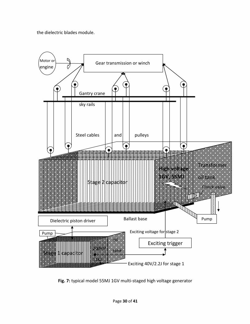
Page 30 of 41
the dielectric blades module.
Fig. 7: typical model 55MJ 1GV multi-staged high voltage generator
Gear transmission or winch
Motor or
engine
Gantry crane
sky rails
Steel cables and pulleys
High voltage 1GV, 55MJ
Stage 1 capacitor 200KV
11KJ
Exciting voltage for stage 2
Dielectric piston driver
Exciting trigger
Exciting 40V/2.2J for stage 1
Stage 2 capacitor
Ballast base
oil
tank
Pump
Pump
Check valve
Transformer
oil tank

Page 31 of 41
When the said ϵ1 is completely inside the capacitor, the oil is displaced to the tank via
the check valve, as well as when the dielectric blades module is lift by the crane, the oil
will flow back and be pumped to the capacitor.
Without check valve and pump, the stage 1 excitation module can be completely
immersed in oil basin, as the volume is far less than the stage 2 module.
As hundreds tones force involved in stage 2 module, the base should be well blasted.
The typical size for such a performance could be 5 meters both wide and height, and 10
to 20 meters long depending on how density the intermediate electrode plates inserted.
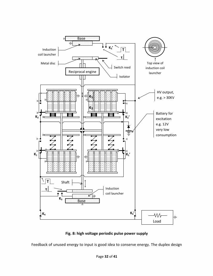
§18. Application in general high voltage periodic pulse generator
When a pulse power supply is customized for a constant load, it is relatively easy
because input and output can be well matched at design stage.
But for universal periodic shots pulse power supply, things are getting complicated,
because the loads are changeable time by time or shot by shot, and the ready
manufactured machine may not be flexible enough to cope with all different loads.
Unmatched application is usually very low efficient and even risks of damage or large
energy waste, just analogous to bombard a mosquito by flak cannon.
Hereby I present an adaptive pulse power supply driven by a reciprocal engine or motor
as power source, and in fact, a rotary engine will be indirectly workable too, just by
simple rotary to reciprocal conversion mechanism, though undrawn in fig. 8.
As manifested in section §12, for a sustainable operation, the generated voltage output
of dielectric blades displacement transformer should be consumed in time, otherwise it
will block next cycle or result in electric breakdown, so that suspension of load, i.e. idling,
is not allowed.
If the load only consumes a small percentage of total pulse energy, then the leftover
energy should be dumped somewhere, or fed back to input.
Page 32 of 41
Fig. 8: high voltage periodic pulse power supply
Feedback of unused energy to input is good idea to conserve energy. The duplex design
Battery for excitation e.g. 12V very low consumption
Shaft
HV output, e.g. > 30KV
Base
Top view of induction coil
launcher
Load
Reciprocal engine
K3’
K3
K4 K4’
ϵ1
ϵ2
K1 K1’
K2 K2’
τ
T
Base
τ
T Induction coil launcher
Metal disc
Isolator
Switch reed
Induction coil launcher
Page 33 of 41
in fig. 8 just follows this good practice. The drive shaft runs through the engine block, so
as to feedback remnant energy from opposite ends.
Because the electrode size is always shorter somewhat than the dielectric blades, so
that either medium ϵ1 or ϵ2 can monopolize the capacitor for a small hesitation time T
during a short reciprocal trip.
As a simple timing means, 2 simple position sensing switches K3 and K3’ are attached to
the induction coil launchers. However, the delay time τ can only be T/2, and the pulse
energy is supposed to be consumed within T/2 after any duet of dielectric blades
triggered respective position switch.
When one dielectric medium is fully displaced out from capacitor, i.e. either switch pair
K1 K1’ or K2 K2’ just turn-on, the timing is beginning, then after τ lapsed, automatically
turn on the respective timing switches to energize the respective induction launcher
with remnant energy to assist the engine.
While one pair capacitor ready to output pulse, simultaneously the other pair capacitor
will begin to be recharged by an excitation battery.
The status of load switches K4 K4’ can be arbitrary so as to feature the load adaptive
performance. When turn off, the machine is totally idling, otherwise either light load,
partially idling or full heavy load.
Someone may wonder why to use a quartet of dielectric blades, it is because that
symmetrical structure claims best mechanic stability. In fact, it is also workable even
reducing to duet structure, as there is full redundancy in the quartet design.
For constant load application, simplification is possible by omitting the remnant
feedback sub-system, i.e. removing the induction coil launchers and associated parts.
§19. Application in utility grade dielectric motor
A simple dielectric displacement motor can be construed as a reciprocal duplex model
showed in fig. 9, though it is only good for fixed load.

Page 34 of 41
Fig. 9: typical duplex reciprocal dielectric motor for fixed load
It comprises basic dielectric media pair, main electrode plates, the inserted electrode
plates that can be wired to main plates via cascade or parallel mode, springs, shaft,
resistors that limit discharge current or recharge current, and switches.
The 5 pieces of dielectric blades combination is only for graphing convenience, in fact,
the real count can be as many as needed in dependence of embodied design. This
statement applies to all figures.
As springs are in tension because of over-stretched apart from equilibrium, as well as
dielectric piston tends to be accelerated because the lower dielectric constant medium
is going to be displaced by the higher one.
At moment of piston approaching dead point, one end position switch connects power
supply with input terminal of capacitor module, and then electrostatic energy is stored.
The grounding sign in the figure is at least the “virtual grounding” that only means all
All this patterns = low
dielectric constant ϵ2
All this patterns = high
dielectric constant ϵ1
Side reciprocal output shaft Also used as hand crank starter
Vinput
K1
K2
R1
R2
Mechanic Load
Page 35 of 41
the same marked terminals are linked together electrically for graphing convenience, in
some cases, real grounding to earth maybe necessary if otherwise specified, but not
always necessary or allowed.
If full loaded, then the remnant voltage after mechanic work output during ϵ2ϵ1 is
(ϵ2/ϵ1)Vin far less than Vin because ϵ1 > ϵ2, hence good efficiency, else if idling, then the
remnant (ϵ2/ϵ1 )0.5Vin > (ϵ2/ϵ1 )Vin. So if using this design to power variable load or
under-rated light load, the efficiency will be very low, because most energy is dissipated
in the discharge resistor R1 then bad heat will be generated.
§20. Application in mobile medical X-ray source
Portable X-ray source is highly desired in many applications, such as battlefield wound
diagnosis, non-destructive detection, crystallography etc.
Conventional X-ray sources are so cumbersome that stimulates industry to try the
downsizing of weight and dimension for the mobile applications.
In principle, X-ray is generated by the bremsstrahlung (braking) effect of high kinetic
electrons, and the normal photon energy is almost half of the electron peak energy.
In recent years, triboelectricity is considered for this application. Unfortunately it is
physically unable to accelerate electron to a decent high energy that is reachable by in-
house X-ray equipment with usual photon energy 150KeV, but mere humble energy up
to 50KeV, hence the application scope is seriously restrained to a niche market.
The action of peeling tape can also produce electrostatic high voltage and weak X-ray on
similar level with previous method. In fact, it is based on triboelectrics too, only by stick-
slip friction instead of rubbing.
Such situation motivates further research on how to create decent high voltage for
mobile application by whatever accessible non-electric power source in situ.
There are multiple choices for operation power where electric power inaccessible
except battery in situ, such as manpower or with hydraulic hand tools, firecracker etc.

Page 36 of 41
Fig. 10 is a hand-pump hydraulic powered mobile X-ray generator.
Fig. 10: simple hand pumped hydraulic mobile pulse X-ray source
The output peak voltage KVp can be controlled by hand pumping as while watching the
voltage meter indication.
The exposure mA parameter is adjusted by changing the filament current so as to
regulate the emission amount of active electrons.
As to the exposure time, it is determined by the capacitor’s total stored energy, hence
not easy adjustable, but in fact, there is no significant impact, because modern digital
100KeV X-ray
X-ray tube
Filament
Exposure mA adjuster
Filter
HV output
K1 Oil ϵ1
Solidϵ2
Pump handle
Excitation battery
Excitationbutton
Voltage meter
Breather
Trapped air
K2
Slice combiner
Page 37 of 41
radiography only need very short exposure time and is not picky to it.
Usually a few milliseconds good enough, and it is easy to meet by optimizing the pairing
of capacitance and the equivalent resistance of X-ray tube.
The initial electrostatic field excitation is manually done by turning on button K1 for a
moment, then it is time to start cranking pump until the wanted high voltage obtained,
and then click button K2 to flash X-ray. Obviously the battery is consumed slightly, so
even cheap regular AA size 1.5V dry cell bank is competent.
Usually a chest posterior anterior X-ray digital image will impose about 0.25mGy dose
radiation for adult patient, so it means even 1J produced X-ray energy is too enough.
According the radiation theory, the X-ray production efficiency equals (7*Z*KVp*10-5) %,
here Z = anode atom number.
For the regular tungsten anode, Z = 74, so if KVp = 100KV, then the efficiency is about
0.5%, it means that only a fractional energy is converted into X-ray, and most energy is
dissipated as heat, so that 200J total input energy is probably enough for once imaging.
Even a lady’s weak hand can easily and quickly and reliably input 200J to this mobile
device by exerting dozens of pump strokes, and the number of strokes depends on the
dielectric media setting.
For example, given the dielectric pair of Mylar and IPPP fire-proof hydraulic oil, then we
have ϵ1 = 6.75, ϵ2 = 3.2, ratio ϵ1/ϵ2 = 2.11, excitation V1 = 12V, the wanted V2 = 200KV.
Solving this equation:
12*(2.11)(n+1)/2 = 200000,
results in solution of stroke sequence number n = {2*log(200000/12)/log2.11} -1 = 25.
Of course, by increasing ratio of ϵ1/ϵ2, the required crank times n can be further reduced,
but enough muscle should be exercised, as there is no change of the total 200J input.
Page 38 of 41
§21. Application in new type propeller of ornithopter aircraft
The aerial propellers in my inventions can mechanically either be the umbrella-like or
planar shape (synonymous designations include board propeller, panel propeller).
The propulsion force usually comes from a short time acting powerful energy release,
such as pulse electromagnetic energy discharge, or explosion driven mechanic thrust.
Dielectric high voltage generators can accumulate the absorbed energy to produce a
high power electric pulse, and such a property can be employed to propel an aerial
vehicle via special propeller.
Just like the webs of duck feet or bird wings, human beings have struggled for many
centuries to experiment flapping-wing aircrafts, or ornithopters that can vertically
takeoff, but still failed to commercialize it.
Once upon commercialization of ornithopters, humankind will benefit in many aspects,
e.g. affordable personal aerial commuting, remote internet service, goods shipping, etc.
By discharging high voltage in capacitors to a base-fixed disc-shape coil that contacts
with a metal disc, such as aluminum disc, the huge current in the coil will induce a very
strong magnetic field, and the induced eddy current in the metal disc will generate a
matchable repelling magnetic field, so as to launch the metal disc in very high velocity.
For example, for a 10KV voltage charged capacitor with 2.2KJ, experiments show that
the pulse discharge can accelerate a 4 ounces projectile to about 160m/s initial speed,
or if driving a realistic aerial vehicle of gross weight 200kg, it may theoretically lift about
2200/(200*9.8) = 1.12m for a single pulse discharge.
I propose the umbrella-like propeller that can perfectly fit the high voltage power supply
comprising dielectric blades displacement module, as is in fig. 11.
According to aerodynamics, for 50m/s typhoon wind speed, the pressure of facing
surface can reach about 150kg/m2, and is roughly proportional to the square of wind
speed. That means 1 square meter umbrella with high enough speed of treading air may
levitate a regular adult plus reasonable weight of driving module.

Page 39 of 41
Fig. 11: duplex umbrella-like propeller for aerial lifter or ornithopter
The higher the initial speed of umbrella, the stronger the propelling force, so by
Dielectric piston HV generator
Gas or diesel Engine
S S S S S
± V ∓ V, e.g. 10kV
max 300m/s
Induction coil launcher
Umbrella-like propeller with
foldable surface &
hinged ribs
Landing legs e.g. tripod
Navigation quadrant
Hinge
Riding room
K1 K2
Metal disc
If umbrella top touches respective coil, then switch ON, else OFF.
Sliding pairs between frame & umbrella mast
Frame
Foldable clothes or leather
Slidable mast
Flexible cable
Air resistant force
S S S S S S
Logic controller
These 2 units can be replaced by rechargeable battery and regular high voltage generator for drone -like Unmanned Aerial Vehicle (UAV)
Page 40 of 41
optimization of design, a proper umbrella area can be determined.
After umbrella full is unfolded then aircraft is pushed some distance, it should return to
the folding status for next propulsion. In the illustrated duplex design, at any transience,
one umbrella is unfolding and another is folding.
In simplex design, i.e. only one umbrella system, folding umbrella can be simpler, even
needless of extra energy input, as luckily the moving vehicle itself can help to retract the
umbrella, i.e. fold it, however small driving power can enhance reliability.
For heavy duty, such as aerial lifter or passenger ornithopter, the power source can be a
regular gas or diesel engine, and the engine usually drives a rotary dielectric
replacement high voltage generator.
For light duty, such as drone-like unmanned aerial vehicle, those 2 units can also be
replaced by rechargeable battery and regular high voltage generator.
The engine can also drive a hydraulic pump first, and then let the hydraulic system drive
a reciprocal dielectric replacement voltage generator via a dual-action hydraulic cylinder.
When the top disc of umbrella touches the launcher coil, the respective switch K1 or K2 is
turned on, high voltage discharge occurs, the umbrella pushes air fiercely, hence
propelling force accelerates vehicle in opposite direction of fanned air.
The whole propeller module is hinged to base of riding room, and navigation can be at
least done by swinging the propeller. If only for home based aerial lifter application,
then horizontal navigation is no longer needed or just a simplest design.
To have more payloads, all parts, including landing legs, the respective material and size
should be well balanced.
Almost all engines in market are the type of rotary, however if the type of reciprocal fuel
engine is accessible, though not good pulse power, it may still be possible to directly
drive the umbrella, just with a large degradation of linear velocity because piston’s
speed of most internal combustion engines is usually at max about 20m/s which is far
inferior to the pulse jerk propelled by electromagnetic catapult, but increasing area of
Page 41 of 41
umbrella can offset the degradation, and in turn, increase of volume and gross weight.
Postscript:
More detail specification regarding all above discussed applications is disclosed in my
patent application USPTO 15/267,122:
Dielectric blade comb piston unlimited voltage generator, fusor and more
Many other applications have not been presented here, because this small paper can
not accommodate so many contents. Anyway, I am considering writing a monograph or
textbook on this new theory and applications of dielectrodynamics.
Perhaps in the near future, it will be the time of saying bye-bye to Marx generator, rare
earth magnetic materials, not affordable personal airplanes, mile-size high energy
particle accelerator, country-size neutron spallation system and more, just cheerfully to
embrace the epoch of powerful inexhaustible fusion energy, convenient personal
ornithopter and other cheap yet useful magnetic-free dielectrodynamic utilities.
§22. Reference literature
1. Smith et al. Alkali-free glass as a high energy density dielectric material. Materials
Letters, 2009; 63 (15): 1245 DOI: 10.1016/j.matlet.2009.02.047
2. Zhou Lin et al. Design of a 5-MA 100-ns linear-transformer-driver accelerator for
wire array Z-pinch experiments. PHYSICAL REVIEW ACCELERATORS AND BEAMS, Vol.
19, Iss. 3, March 2016; DOI: 10.1103/PhysRevAccelBeams.19.030401
3. Mazarakis, et al. Linear Transformer Drivers (LTD) for high voltage, high current
rep-rated systems. In Proceedings of the 2010 IEEE International Power Modulator
and High Voltage Conference, IPMHVC 2010, 5958297, pp. 69-74, 2010 IEEE
International Power Modulator and High Voltage Conference, IPMHVC 2010, Atlanta,
GA, United States, 23-27 May. DOI: 10.1109/IPMHVC.2010.5958297