diesel engine report
DESCRIPTION
Details on diesel engine power plantTRANSCRIPT
ME 521 – POWER PLANT DESIGN
2014
1
Aljon M. Altiche
Efrel John L. Manlapaz
Romyrick L. Gliponeo
Emannoel M. Brimon

In a diesel power station, diesel engine is used as the
prime mover. The diesel burns inside the engine and
the products of this combustion act as the working
fluid to produce mechanical energy. The diesel engine
drives alternator which converts mechanical energy
into electrical energy.
2

Diesel power plants is in the range of 2 to 50 MW capacity. They
are used as central station for small or medium power supplies.
They can be used as stand-by plants to hydro-electric power
plants and steam power plants for emergency services.
They can be used as peak load plants in combinations with
thermal or hydro-plants.
They are quite suitable for mobile power generation and are
widely used in transportation systems such as automobiles,
railways, air planes and ships.
Now-a-days power cut has become a regular feature for
industries. The only solution to tide over this difficulty is to install
diesel generating sets.
3

Diesel Engine
Air intake system
Exhaust system
Fuel supply system
Cooling system
Lubricating system
Starting system
4

5

6

7

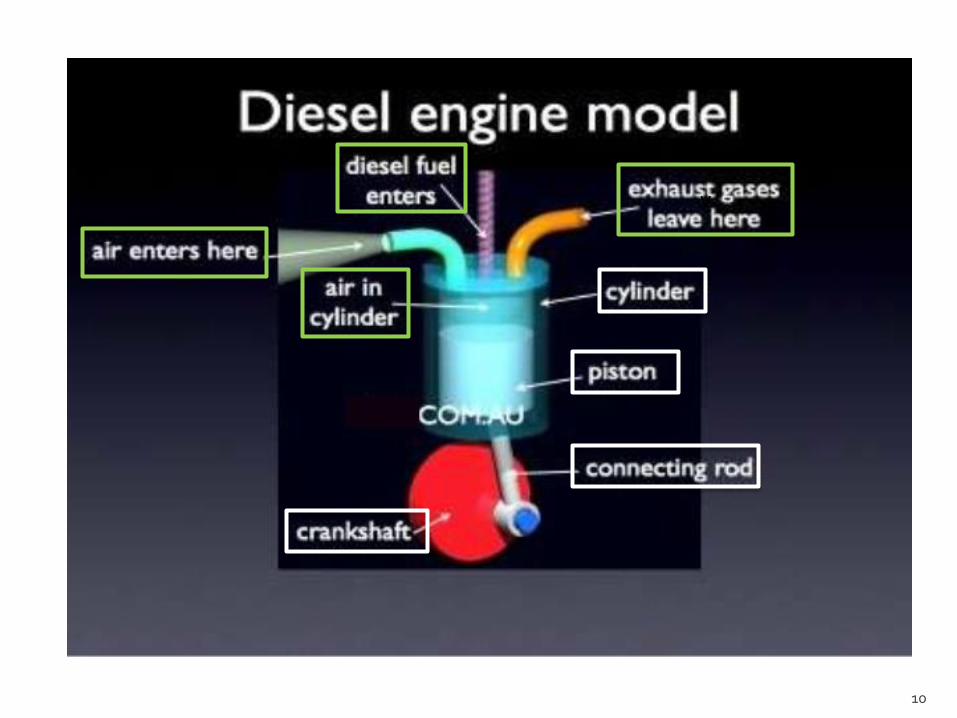
A diesel engine (also known as a compression-
ignition engine) is an internal combustion
engine that uses the heat of compression to initiate
ignition and burn the fuel that has been injected into
the combustion chamber. This contrasts with spark-
ignition engines such as a petrol engine(gasoline
engine) or gas engine (using a gaseous fuel as
opposed to gasoline), which use a spark plug to ignite
an air-fuel mixture.
8
This occurs in two steps. First, the fuel reacts
chemically (burns by self ignition) and releases energy
in the form of heat. Second the heat causes the
gasses trapped in the cylinder to expand, and the
expanding gases, being confined by the cylinder, must
move the piston to expand. The reciprocating motion
of the piston is then converted into rotational motion
by the crankshaft.
9
10
v

1. Suction stroke, with inlet valve open, fills cylinder with air.
2. Compression stroke raises pressure to about 35kg/cm2.
Fuel injection starts at or near end of compression stroke.
3. High air temperature caused by compression ignites fuel.
Burning mixture expands, pushing piston down on working stroke.
4. Exhaust valve open: rising piston clears cylinder.
11

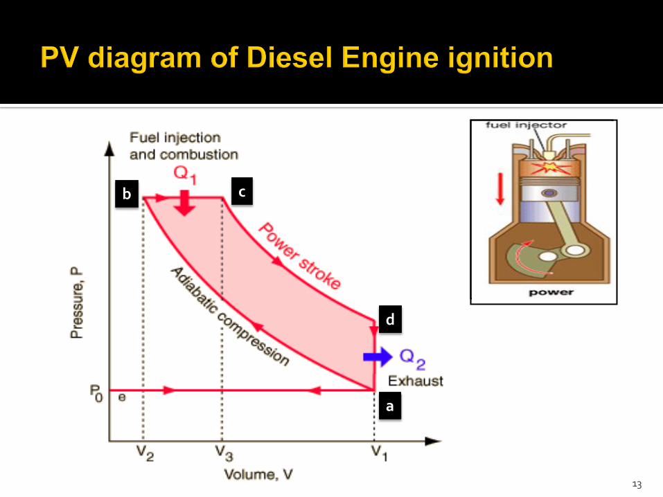
The ideal thermal cycle of the Diesel engine begins with
the working medium at state 1, it is first polytropically
compressed to state 2, then heat is added during a limited
isobaric expansion, after which a polytropic expansion to
the initial volume reduces pressure to state 4. The ideal
work produced by the cycle is represented by its area, and
the mean effective pressure is its average height.
12
13
a
b c
d

4 Stroke Diesel Engine
is an internal combustion engine in which the piston completes
four separate strokes which comprise a single thermodynamic cycle
2 Stroke Diesel EngineLike the four-stroke engine, the two-stroke engine must go
through the same four events: intake, compression, power, and
exhaust. But a two-stroke engine requires only two strokes of the
piston to complete one full cycle(crankshaft).
14
INTAKE
EXHAUST
Two stroke diesel engine:

15

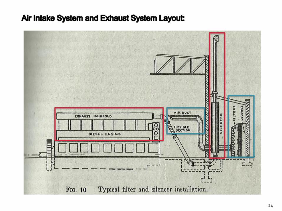
A system with air filters, ducts and supercharger that
supplies necessary air to the engine for fuel
combustion. It consists of pipes for the supply of fresh
air to the engine manifold. Filters are provided to
remove dust particles from air which may act as
abrasive in the engine cylinder.
It also improves the turbocharged or supercharged
engine’s efficiency, and it cools the compressed air
after being compressed.
16

Dry Filter – A type of system where paper, cloth, or a
metal screen material is used to catch and trap dirt
before it enters the engine.
Wet Filter – In this system the air is sucked or
bubbled through a housing that holds a bath of oil
such that the dirt in the air is removed by the oil in the
filter. The air then flows through a screen-type material
to ensure any entrained oil is removed from the air.
17

18Wet Filter Air Intake System
To E
ng
ine

19

20
A system that leads the engine exhaust gas outside
the building and discharges it into atmosphere. A
silencer is usually incorporated in the system to
reduce the noise level. It is mainly composed of
manifold, cylinders, muffler and exhaust pipe.

21
Silencer
Expansion Joint
Exhaust manifoldCylinders

First, the exhaust system routes the spent combustion
gasses away from the engine, where they are diluted
by the atmosphere. This keeps the area around the
engine habitable.
Second, the exhaust system confines and routes the
gases to the turbocharger, if used.
Third, the exhaust system allows mufflers to be used
to reduce the engine noise.
22

a. The noise should be reduced to a tolerable degree.
b. It should be exhausted well above the ground level
to reduce the air pollution at breathing level.
c. The pressure loss in the system should be reduced
to minimum.
d. The vibrations of exhaust system must be isolated
from the plant by use of flexible exhaust pipe.
e. A provision should be made to extract the heat from
exhaust if the heating is required for fuel oil heating
or building heating or process heating.
23
24

25

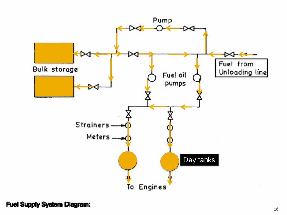
A system consists of storage tank, strainers, fuel
transfer pump and all day fuel tank.
26

a. The fuel oil is supplied at the plant site by rail or
road. The oil is stored in the storage tank.
b. From the storage tank, oil is pumped to smaller all
day tank at daily or short intervals.
c. From this tank, fuel oil is passed through strainers to
remove suspended impurities.
d. The clean oil is injected into the engine by fuel
injection pump (fuel injection system).
27
28
Day tanks
Simple Suction system
In a simple suction system, the oil is taken by a suction pump
driven by engines from service tank located a few cm below the engine
level. Such pump delivers constant volume of fuel, therefore, an
overflow line is required back to the tank. This system is used for small
capacity plant.
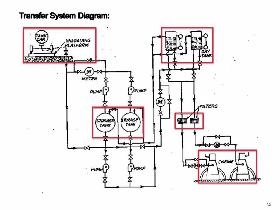
Transfer system
In transfer system, the motor driven pump takes the oil from
main storage and supply to the day storage tank. The oil from day-
storage tank flows under gravity to the engine pump.
29
30

31

A system that includes water circulating pumps,
cooling towers or spray ponds and water filtration
plant. Small engines may be served with a cellular
heat exchanger (radiator), through which the air is
drawn by means of fan.
32
If the engines are not properly cooled, the
temperature existing inside engines would disintegrate
the film of lubricating oil on the liners and wrapping of
valves and pistons takes place. The proper cooling of
the engine is absolutely necessary to extend the life of
the plant. Therefore, exit temperature of the cooling
water must be controlled. If it is too low, lubricating oil
will not spread properly and wearing of piston and
cylinder takes place. If it is too high, the lubricating oil
burns. Therefore, the maximum exit temperature of
the water is limited to 70°C.
33

34
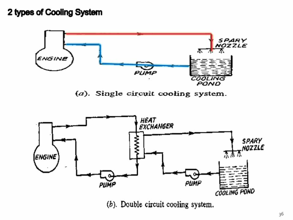
The temperature of the burning fuel inside the engine
cylinder is 15000C to 20000C. In order to lower this
temperature water is circulated around the engine.
The hot water leaving the jacket is passed through the
heat exchanger.
The heat from the heat exchanger is carried away by
the raw water circulated through the heat exchanger
and is cooled in the cooling tower

35
to Oil
Cooler
36

37

A system that includes the oil pumps, oil tanks, filters,
coolers and connecting pipes. The function of the
lubrication system is to reduce the friction of moving
parts, reduce the wear and tear of the engine parts
and also helps to cool the engine .
38

The role played by the lubrication system in diesel
power plant is more important than any other plant
because of very high pressures and small clearance
in these engines. The life of the engine, the overall
efficiency of the plant and possible continuous service
of the plant are dependent on the effectiveness of the
lubrication system.
39

Piston and cylinders
Crankshaft and connecting rod bearings
Gears or other mechanism designed to transmit
motion to auxiliaries.
Integral injection or scavenging air compressors.
40

41

42

Engine Starting by an auxiliary small engine
Compressed air system
Starting by electric motor
43

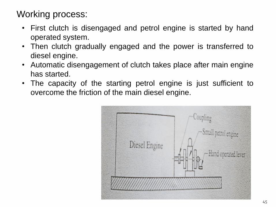
It is composed of two engine:
1. Diesel engine that is main engine.
2. Small petrol engine.
44
Joining:
• Diesel engine and petrol engine are joined by clutch and gear
arrangements.
• Small petrol engine can be easily started by means of manual
operations
45
Working process:
• First clutch is disengaged and petrol engine is started by hand
operated system.
• Then clutch gradually engaged and the power is transferred to
diesel engine.
• Automatic disengagement of clutch takes place after main engine
has started.
• The capacity of the starting petrol engine is just sufficient to
overcome the friction of the main diesel engine.

The compressed air system is generally used for
starting large diesel engine employed for power plant.
In this system compressed air a pressure of 17 bar is
supplied from an air bottle to the engine cylinder either
through a distributor or directly through inlet manifold.
In case of multicylinder engines, at least one cylinder
remains on the suction stroke.
46

47
Working process:
• When compressed air under the pressure enters cylinder, it
pushes the cylinder thereby causing entire engine crankshaft
assembly to rotate.
• Meanwhile the suction stroke of some other cylinder takes place
and the compressed air again pushes the piston of this cylinder
and causes the engine crank assembly to rotate.
• Gradually the engine gains momentum and by turning on the fuel
supply, engine will start running.

This system consists of an electric motor which is
drives pinion which engages a gear toothed rim on
engine.
A storage battery of 12 to 36 volts is used to supply
power to an electric motor.
The main advantages of electric starting are its
simplicity and effectiveness. This system is used for
small diesel engine.
48

The engine should not be stopped abruptly. In order to
stop engine, the speed should be decreased gradually
until no power is delivered by generator .Then the
engine is disconnected from the bus bars and is
allowed to run idle for some time.
49
Stopping fuel supply
Keeping exhaust valve open
Shutting of air supply
Stopping the action of injection pump.
50

51

Plant layout is simple. Hence it can be quickly installed
and commissioned, while the erection and starting of a
steam power plant or hydro-plant takes a fairly long time.
Quick starting and easy pick-up of loads are possible in a
very short time.
The load operation is easy and requires minimum labours.
Efficiency at part loads does not fall so much as that of a
steam plant.
Fuel handling is easier and no problem of ash disposal
exists.
The plant is smaller in size than steam power plant for
same capacity.52
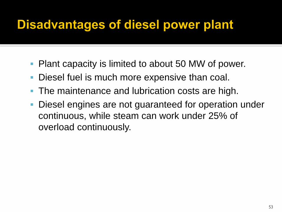
Plant capacity is limited to about 50 MW of power.
Diesel fuel is much more expensive than coal.
The maintenance and lubrication costs are high.
Diesel engines are not guaranteed for operation under
continuous, while steam can work under 25% of
overload continuously.
53

54

55
DMPC – CATAINGAN
SATELLITE PLANT
DMPC – AROROY
SATELLITE PLANT
DMPC – MAIN
PLANT
56
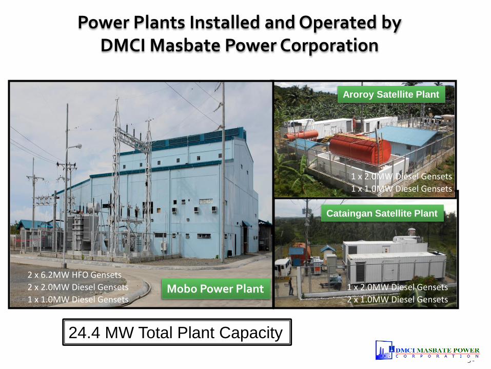
Power Plants Installed and Operated by DMCI Masbate Power Corporation
2 x 6.2MW HFO Gensets
2 x 2.0MW Diesel Gensets 1 x 2.0MW Diesel Gensets
2 x 1.0MW Diesel Gensets
1 x 2.0MW Diesel Gensets
1 x 1.0MW Diesel Gensets
1 x 1.0MW Diesel GensetsMobo Power Plant
Cataingan Satellite Plant
Aroroy Satellite Plant
24.4 MW Total Plant Capacity
57
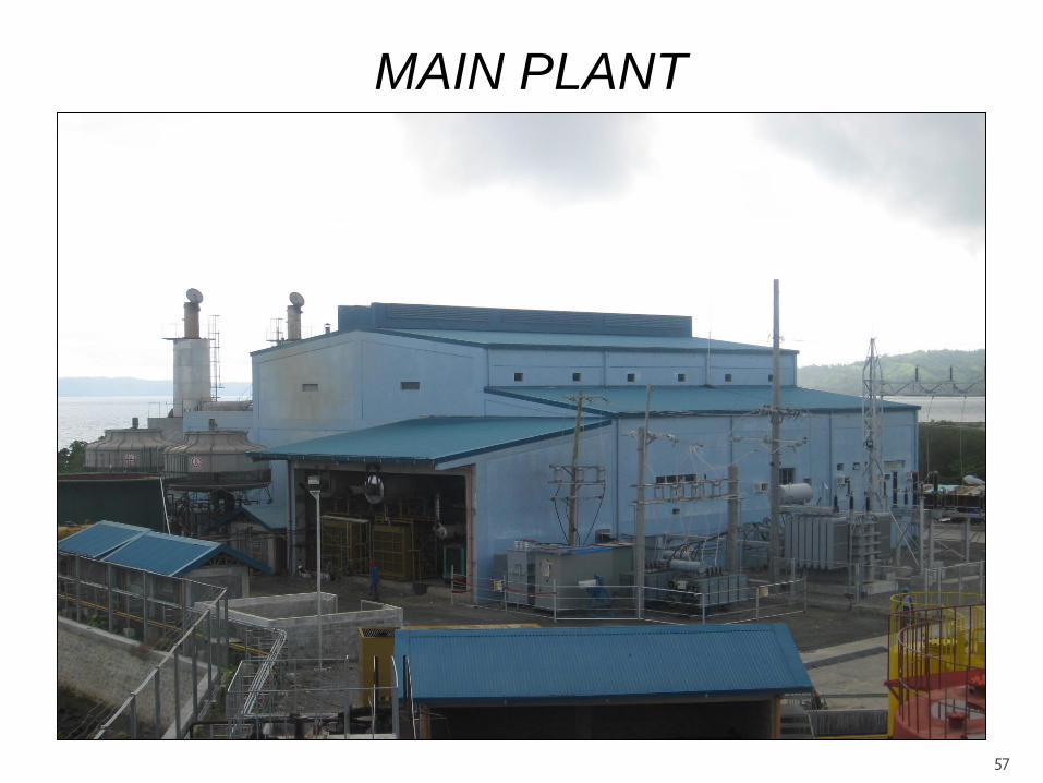
MAIN PLANT

58
MAIN PLANT
CAPACITY & CONFIGURATION
GENERATOR UNITS Speed (Category) Installed MW CapacityDependable MW
Capacity
NIIGATA 1 600 RPM (Medium Speed) 6.2 5.8
NIIGATA 2 600 RPM (Medium Speed) 6.2 5.8
CATERPILLAR 1 1800 RPM (High Speed) 2.0 1.6
CATERPILLAR 2 1800 RPM (High Speed) 2.0 1.6
MITSUBISHI 3 1800 RPM (High Speed) 1.0 0.8

59
CATAINGAN SATELLITE PLANT
60
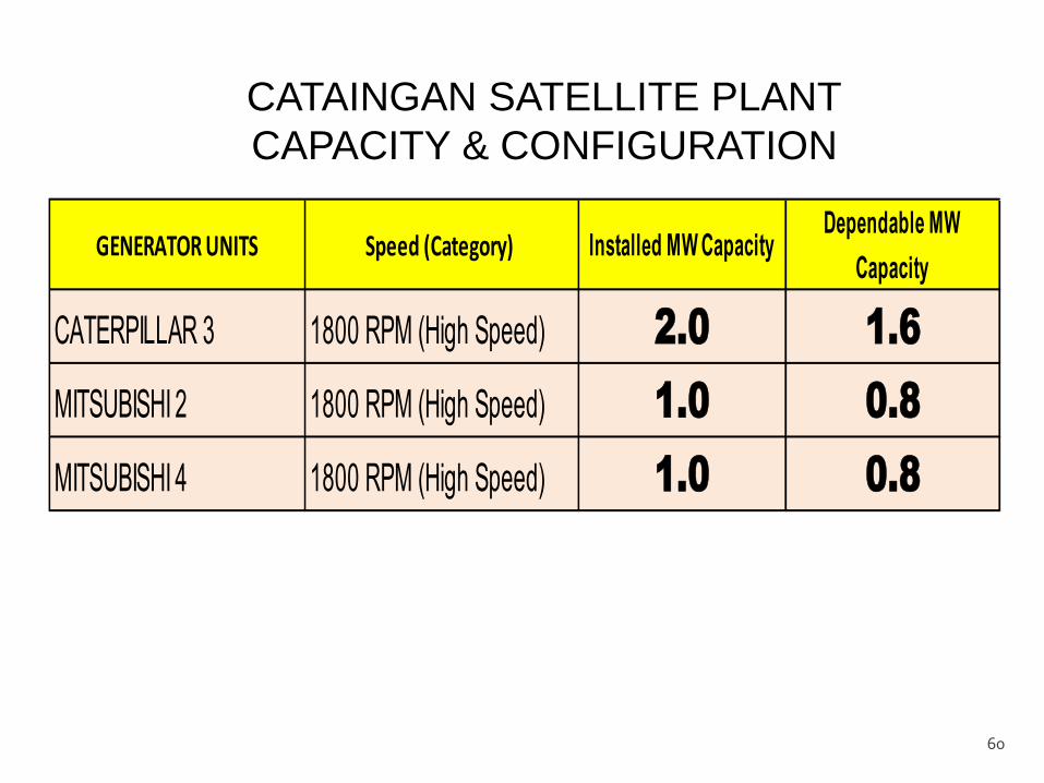
CATAINGAN SATELLITE PLANT
CAPACITY & CONFIGURATION
GENERATOR UNITS Speed (Category) Installed MW CapacityDependable MW
Capacity
CATERPILLAR 3 1800 RPM (High Speed) 2.0 1.6
MITSUBISHI 2 1800 RPM (High Speed) 1.0 0.8
MITSUBISHI 4 1800 RPM (High Speed) 1.0 0.8
61
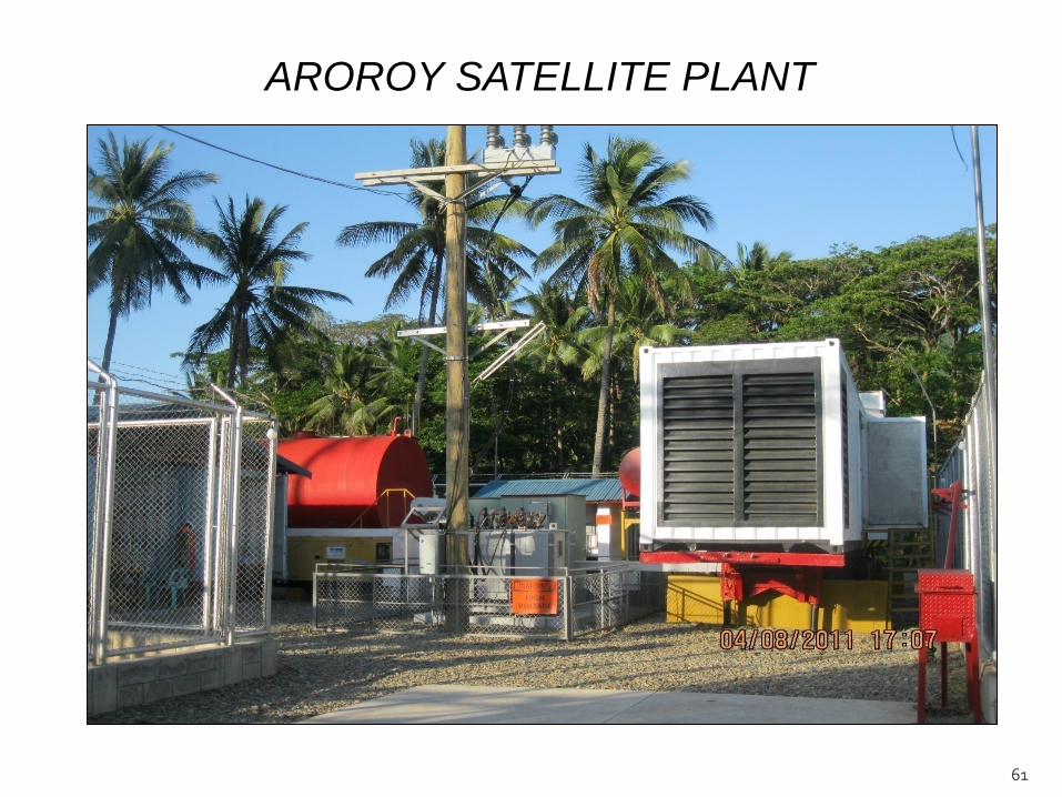
AROROY SATELLITE PLANT

62
AROROY SATELLITE PLANT
CAPACITY & CONFIGURATION
GENERATOR UNITS Speed (Category) Installed MW CapacityDependable MW
Capacity
CATERPILLAR 4 1800 RPM (High Speed) 2.0 1.6
MITSUBISHI 1 1800 RPM (High Speed) 1.0 0.8

63
DIESEL ENGINES
Main Plant,
Mobo
(MW)
Curvada,
Cataingan
(MW)
Bangon,
Aroroy
(MW)
TOTAL
(MW)
NIIGATA 1 6.2 6.2
NIIGATA 2 6.2 6.2
CATERPILLAR 1 2.0 2.0
CATERPILLAR 2 2.0 2.0
CATERPILLAR 3 2.0 2.0
CATERPILLAR 4 2.0 2.0
MITSUBISHI 1 1.0 1.0
MITSUBISHI 2 1.0 1.0
MITSUBISHI 3 1.0 1.0
MITSUBISHI 4 1.0 1.0
TOTAL INSTALLED
CAPACITY (In MW) 17.4 4.0 3.0 24.4
POWER PLANT’S INSTALLED CAPACITY

64
DIESEL ENGINES
Main Plant,
Mobo
(MW)
Curvada,
Cataingan
(MW)
Bangon,
Aroroy
(MW)
TOTAL
(MW)
NIIGATA 1 5.8 5.8
NIIGATA 2 5.8 5.8
CATERPILLAR 1 1.6 1.6
CATERPILLAR 2 1.6 1.6
CATERPILLAR 3 1.6 1.6
CATERPILLAR 4 1.6 1.6
MITSUBISHI 1 0.8 0.8
MITSUBISHI 2 0.8 0.8
MITSUBISHI 3 0.8 0.8
MITSUBISHI 4 0.8 0.8
DEPENDABLE
CAPACITY (In MW) 16.4 2.4 2.4 21.2
POWER PLANT’S DEPENDABLE CAPACITY

65
Why Satellite Plant Exists?
1. It is the DMPCs alternative solution in the absence of
NPCs 69 KV Transmission Line (A government’s
unfinished project).
2. Due to a long extended 13.8 KV Distribution Line of
MASELCO which resulted in a “Low Voltage” in the far
end of the DT.
What are its Primary Purposes?
1. To correct “Low Voltage” Problem at far end.
2. To minimize “System Loss” of the Off taker.
3. To minimize prolong “Brownouts” at areas affected by
Line Repair Maintenance.
4. To bring more “Reliable Power” to the consumers.
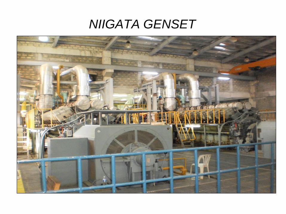
NIIGATA GENSET
67
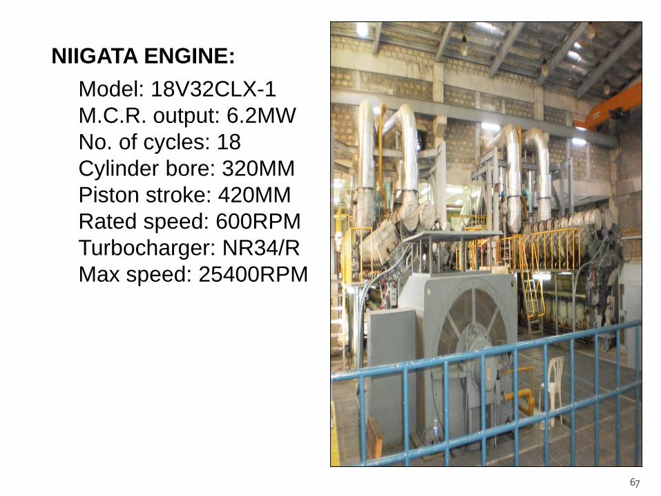
NIIGATA ENGINE:
Model: 18V32CLX-1
M.C.R. output: 6.2MW
No. of cycles: 18
Cylinder bore: 320MM
Piston stroke: 420MM
Rated speed: 600RPM
Turbocharger: NR34/R
Max speed: 25400RPM

68
CATERPILLAR GENSET
69
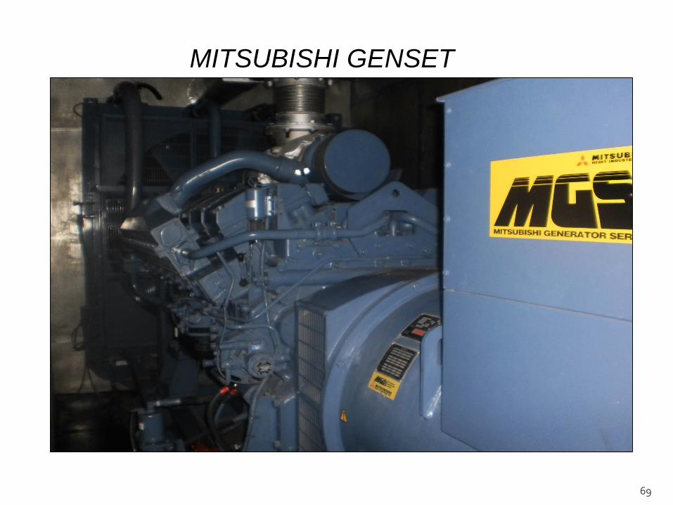
MITSUBISHI GENSET

70
AIR INTAKE SYSTEM
AIR INTAKE FILTER
“Auto-mazed Air Filter”

71
LUBE OIL SYSTEM

72

73

74

75
COOLING SYSTEM
COOLING SYSTEM
100KL RAW WATER
STORAGE TANK
76
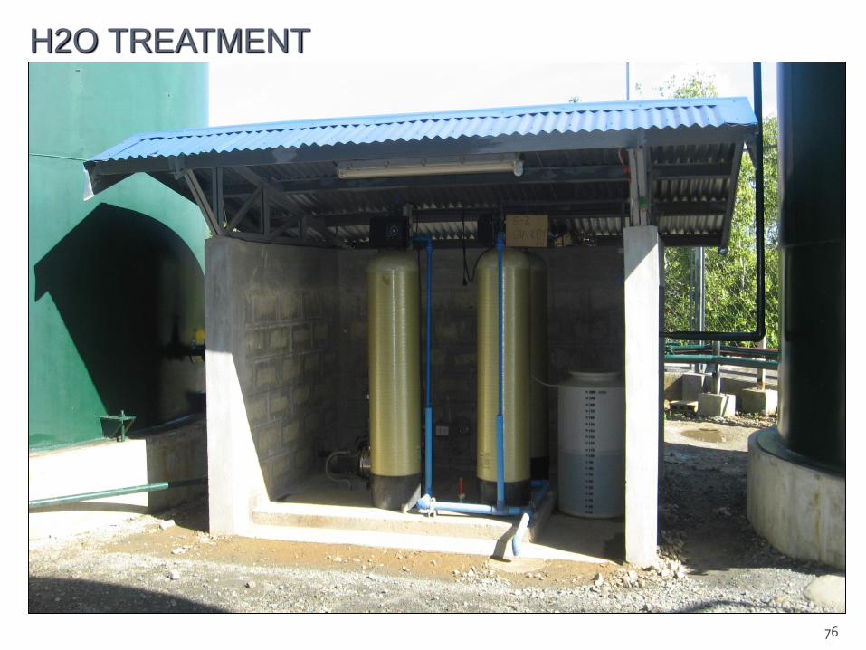
H2O TREATMENT

77
PRIMARY COOLING SYSTEM
20KL SOFT H2O
STORAGE TANK

78
PRIMARY COOLING SYSTEM
JACKET H2O PUMP – 30KW

79
SECONDARY COOLING SYSTEM
MODEL: LBC 500
NOMINAL H2O FLOW: 6500L/M
AIR VOLUME: 2600M3/M

80
SECONDARY COOLING SYSTEM
AIRCOOLER

81
SECONDARY COOLING SYSTEM
LUBE OIL COOLER
RAW WATER IN
82
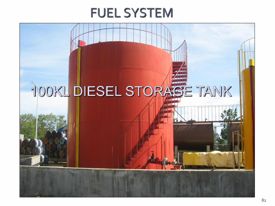
FUEL SYSTEM

83

84
FUEL SYSTEM DRAIN
85
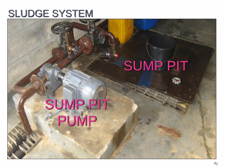
SLUDGE SYSTEM
SUMP PIT
SUMP PIT
PUMP

86
EG – 160 (438 KVA)

87
SLUDGE STORAGE AREA
88
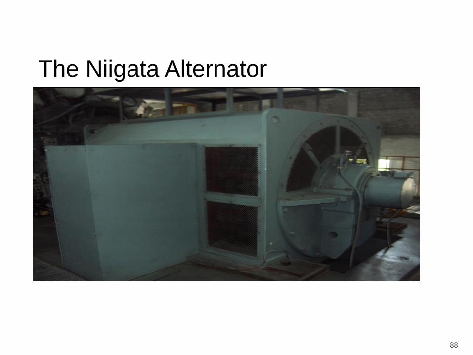
The Niigata Alternator

89
MEDIUM VOLTAGE SWITCHGEAR
BUS PT
PANEL
NII-2
PANEL
NII-1
PANEL
20-MVA
X’FORMER
PANEL
1.5-MVA
AUX.
X’FORMER
PANEL
Single Line Diagram

90
CONTROL ROOM
ENGINE-1 ENGINE-2
SYNCHRONIZIN
G PANEL
AMC-1 /
AMC-2
ANCILIARY
CONTROL
PANEL
91
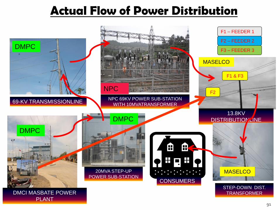
Actual Flow of Power Distribution
69-KV TRANSMISSIONLINENPC 69KV POWER SUB-STATION
WITH 10MVATRANSFORMER
13.8KV
DISTRIBUTIONLINE
CONSUMERS
DMCI MASBATE POWER
PLANT
20MVA STEP-UP
POWER SUB-STATION
F1 & F3
F2
F1 – FEEDER 1
F2 – FEEDER 2
F3 – FEEDER 3
STEP-DOWN DIST.
TRANSFORMER
DMPC
DMPC
MASELCO
MASELCO
DMPC
NPC
92

93
At shaft under ISO conditions = 6600 kW
Number of strokes = 4 (four)
Cylinder Power = 550 kW/cylinder
Number of cylinders = 12
Nominal speed = 600 rpm
Diesel Engine Unit = 3
Capacity Installed = 18.9 MW
Capacity Dependable = 14.9 MW

94
OPERATION PROCEDURES
Pre-Operation Procedures
Verify order of operation with Shift Supervisor On-duty prior to carrying out pre-
startup procedures.
Visually check the Jacket Water [JW] and Injector Cooling [IC] Water
expansion tanks for proper level.
Check inlet and outlet valves of Nozzle and Jacket Waters systems for proper
open or close positions.
Press JW and NC water pumps start button located on the Engine Control
Panel [ECP].
Energize JW and IC water heaters by pressing the “ON” button located on the
Heaters Control Panel [HCP].
Check the level of the various engine tanks and auxiliary equipment.
Cooling Tower Pond
Oil Sump Tank
Cylinder Lubricating Oil Tank
Bunker fuel service and settling tank
Diesel storage tanks
Turbocharger oil level
Governor oil level
Outboard bearing oil level
Air pressure for 30 and 8 bar tanks

95
Verify that fuel control linkages and injection pump plunges moves freely.
Manually lubricate cylinder liners by turning the hand crank of the cylinder
lubricators and check that excessive force is not needed to turn the cranks.
Check that the various valves for the engine cooling, lubrication, fuel system and
air system are in the correct position.
Verify with Auxiliary Operator/Maintenance that the lube oil separator/centrifuge
of engine in schedule has been running normally. (The separator must be put in
operation at least four hour before engine operation to remove accumulated dirt
or settled water, if any).
Run bunker fuel centrifuge (if no engine running).
Start the Pre-lubricating oil pump.
Open the indicator cocks in the cylinder heads and rotate the engine several
times with the turning gear to make sure that no water, oil, or fuel has collected in
the cylinder.
Switch “OFF” the JW and IC heaters and switch-off the injector and jacket water-
circulating pumps.
Switch “OFF” the turning gear motor, disengage the turning gear, and lock the
operating lever.

96
Start-Up Procedure
Energize main power supply for the engine alarm.
Start up the following and adjust the pressures:
Pre-lubricating oil pump (manual position)
Diesel transfer pump
Fuel booster module
Nozzle cooling water pump
Jacket water pump
Fuel service pump
Check that the turning gear is disengaged and that the operating lever is locked.
Open all the indicator cocks.
Check starting air tank pressure gauge for the proper pressure of 25 to 30 bar.
Set the governor load limit to “0” position, and rotate the speed setting knob for at
least five [5] revolutions from zero.
Set the governor speed droop to “40” position.
Move each individual fuel pump rack in and out a few times to ensure rack is free
and not binding.
Press the emergency stop button.
Open the starting air valve.
Get clearance and “GO” signal with Shift Supervisor On-duty for startup activation.

97
Gradually unload (300 KW/min) the generator to avoid extreme thermal
stressing.
Open/trip the generator circuit breaker just before the KW-hr meter reaches 200
KW.
Let the generator run for at least 10 to 15 minutes to cool down the engine.
Set alarm power switch to “DISABLE” position.
Bring down the engine speed gradually and press the emergency stop button.
Open all indicator valves to release air from the cylinders. The engine should
stop running after 20 to 30 seconds.
Push control buttons of the following to “OFF” position.
Raw water pump
Cooling tower fan motor
Jacket water pump
njector cooling water pump
Switch “OFF” the chemical feed pump
Close the starting air main valves.
Switch “OFF” the pre-lube pump.
Switch “OFF” main power supply of ECP.
Stopping Procedures
98
MAINTENANCE PROCEDURES
The maintenance work to be carried out on the engine at regular
intervals is described in the maintenance schedule and is to be understood as
a guide. The maintenance intervals are dependent on the mode of operation
and load as well as on the quality of the fuel used.
Precautionary Measure For Maintenance Work
Prior to carrying out any maintenance work on the engine (especially
on the running gear), the following precautions have to be taken.
Pull out the Vacuum Circuit Breaker of generator engine under maintenance to
avoid accidental closing.
Installation of automatic control: Put automatic control switch to “OFF” position.
Close stop valves of starting air receivers.
Open all indicator cocks on the cylinder heads and leave in this position until
maintenance work is completed.
Engage turning gear (gear pinion must bee in engage position) and lock the
lever.
In case the engine had to be stopped due to overheated running gear
or bearings, wait at least 10 minutes before opening the crankcase doors.
99
Recommendations For Carrying Out The Work
Prior to turning the crankshaft with the turning gear, make sure that no loose
parts, tools or devices can get jammed.
When carrying out maintenance works, use the tools and devices intended for
the work.
Tools and devices should be ready prior to use and be in perfect conditions.
Hydraulic tools are to be checked from time to time for tightens and perfect
functioning.
All work must be done carefully, observing utmost cleanliness.
Where openings appear after certain parts have been removed, pipelines, oil
holes, etc., they must be temporarily closed off in order to prevent entry of any
dirt into the engine.
All parts overhauled during the course of servicing have to be checked for
perfect functioning before reinstalling back into service.
Pipes that have been removed have to be checked for tightness after refitting.
Clearances of moving parts must be checked periodically. Should the maximum
permissible values have been reached or exceeded, these parts must be
replaced.
When tightening studs, nuts or bolts, the utmost care must be taken not to
damage their threads and that they can be screwed in by hand until metal-to-
metal contact is obtained. The specified lubricants are to be used.

100