diesel generating sets - powertech engines...iveco motors diesel generating sets - instruction...
TRANSCRIPT
DIESELGENERATINGSETSINSTRUCTION MANUAL
EDITION JULY 2005T
EC
HN
OL
OG
IC
AL
E
XC
EL
LE
NC
E
Publication IVECO MOTORS edited by:IVECO PowerTrainAdvertising & PromotionPregnana Milanese (MI)www.ivecomotors.com
Printed P4D63Z001E - July 2005 Edition
Iveco Motors Diesel Generating Sets - Instruction Manual
page 2 of 47
Iveco Motors Diesel Generating Sets - Instruction Manual
page 3 of 47
CONTENTS
1. INTRODUCTION.............................................................................................................................................................................................................. 51.1. AIMS AND APPLICATION OF THE MANUAL .................................................................................................................................................... 51.2. USING THE MANUAL....................................................................................................................................................................................................... 5
1.2.1. IMPORTANCE OF THE MANUAL ........................................................................................................................................................................................ 51.2.2. DEFINITIONS..................................................................................................................................................................................................................... 51.2.3. SYMBOLS........................................................................................................................................................................................................................... 61.2.4. WARNING LABELS............................................................................................................................................................................................................ 7
1.3. REFERENCE DOCUMENTS............................................................................................................................................................................................ 81.4. FACSIMILE OF THE EC CONFORMITY DECLARATION.............................................................................................................................. 91.5. RELEVANT LEGISLATION .............................................................................................................................................................................................101.6. MARKING ................................................................................................................................................................................................................................111.7. GUARANTEE.........................................................................................................................................................................................................................121.8. SPARE PARTS ........................................................................................................................................................................................................................12
2. OPERATING CONDITIONS AND LIMITS ......................................................................................................................................... 132.1. GENERAL ................................................................................................................................................................................................................................ 132.2. ENVIRONMENTAL LIMITS ............................................................................................................................................................................................ 13
2.2.1. STANDARD ENVIRONMENTAL CONDITIONS .................................................................................................................................................................... 132.2.2. DERATING FOR ENVIRONMENTAL CONDITIONS ............................................................................................................................................................. 13
2.3. OPERATING LIMITS ..........................................................................................................................................................................................................162.3.1. GENERAL .........................................................................................................................................................................................................................162.3.2. POWER RATING ..............................................................................................................................................................................................................162.3.3. FREQUENCY.....................................................................................................................................................................................................................162.3.4. VOLTAGE.........................................................................................................................................................................................................................172.3.5. POWER FACTOR..............................................................................................................................................................................................................172.3.6. SINGLE-PHASE LOAD .......................................................................................................................................................................................................172.3.7. LOAD TAKE-UP ...............................................................................................................................................................................................................18
2.4. IMPROPER USE.....................................................................................................................................................................................................................192.5. MODIFICATIONS TO OPERATING DATA......................................................................................................................................................... 20
2.5.1. FREQUENCY CHANGE .................................................................................................................................................................................................... 202.5.2. VOLTAGE CHANGE ........................................................................................................................................................................................................ 20
2.6. TYPES OF OPERATION ................................................................................................................................................................................................. 20
3. SAFETY...........................................................................................................................................................................................................................................213.1. GENERAL ................................................................................................................................................................................................................................213.2. ACCESS TO THE PLANT................................................................................................................................................................................................213.3. SAFETY REQUIREMENTS DURING INSTALLATION AND COMMISSIONING .............................................................................213.4. SAFETY REQUIREMENTS DURING MAINTENANCE.................................................................................................................................... 23
3.4.1. GENERAL PRECAUTIONS................................................................................................................................................................................................. 233.4.2. ENGINE COOLING CIRCUIT ........................................................................................................................................................................................... 243.4.3. LUBRICATING CIRCUIT ................................................................................................................................................................................................... 243.4.4. FUEL CIRCUIT................................................................................................................................................................................................................. 243.4.5. EXHAUST CIRCUIT.......................................................................................................................................................................................................... 243.4.6. ELECTRIC START SYSTEM................................................................................................................................................................................................ 243.4.7. SYNCHRONOUS GENERATORS........................................................................................................................................................................................ 253.4.8. ELECTRIC PANEL............................................................................................................................................................................................................. 25
3.5. DURING OPERATION.................................................................................................................................................................................................... 25
4. DESCRIPTION OF THE MACHINE ............................................................................................................................................................ 264.1. GENERAL ............................................................................................................................................................................................................................... 26
4.1.1. SPECIAL APPLICATIONS................................................................................................................................................................................................... 264.1.2. ON-BOARD SETS ........................................................................................................................................................................................................... 26
4.2. COMPOSITION OF STANDARD IVECO MOTORS GENERATING SETS.......................................................................................... 27
5. TRANSPORT AND HANDLING ................................................................................................................................................................... 285.1. USING STATIONARY, MOBILE OR BRIDGE CRANES ................................................................................................................................. 295.2. USING A FORK LIFT TRUCK...................................................................................................................................................................................... 295.3. UNPACKING ....................................................................................................................................................................................................................... 29
Iveco Motors Diesel Generating Sets - Instruction Manual
page 4 of 47
6. INSTALLATION.................................................................................................................................................................................................................. 306.1. GENERAL INSTALLATION CRITERIA.................................................................................................................................................................... 306.2. IMPORTANT INFORMATION.................................................................................................................................................................................... 30
6.2.1. INSPECTION OF MATERIALS ............................................................................................................................................................................................ 306.2.2. PRELIMINARY INSTALLATION PROCEDURES FOR AUTOMATIC GENERATING SETS ........................................................................................................... 306.2.3. SAFETY STANDARDS FOR DIESEL ENGINES ..................................................................................................................................................................... 30
6.3. INSTALLATION...................................................................................................................................................................................................................316.3.1. OUTDOOR INSTALLATIONS .............................................................................................................................................................................................316.3.2. INDOOR INSTALLATIONS .................................................................................................................................................................................................31
7. START-UP.................................................................................................................................................................................................................................. 42
8. OPERATION .......................................................................................................................................................................................................................... 428.1. PROCEDURES FOR THE OPERATION OF MANUAL AND AUTOMATIC UNITS ....................................................................... 42
9. MAINTENANCE ................................................................................................................................................................................................................ 439.1. MANUALLY CONTROLLED SETS............................................................................................................................................................................ 439.2. AUTOMATIC SETS............................................................................................................................................................................................................ 44
9.2.1. INSTRUCTIONS FOR IDLING TEST ................................................................................................................................................................................... 449.3. STARTER BATTERIES AND AUXILIARY SERVICES......................................................................................................................................... 45
9.3.1. GENERAL REQUIREMENTS ............................................................................................................................................................................................... 459.3.2. CLEANING...................................................................................................................................................................................................................... 45
9.4. TROUBLESHOOTING .................................................................................................................................................................................................... 45
10. DEMOLITION....................................................................................................................................................................................................................... 47
Iveco Motors Diesel Generating Sets - Instruction Manual
page 5 of 47
1. INTRODUCTION
1.1. AIMS AND APPLICATION OF THE MANUAL
The aim of this manual is to provide the instructions and information necessary for the correct and safe installation, operation and maintenance of the generating set throughout its operational life from delivery to fi nal disposal.
The content of the manual applies to the entire range of Iveco Motors diesel generating sets.
For information on the characteristics of the various models of generator sets and the relative motors, refer to the applicable Iveco Motors publications. Similarly, for information on the generators themselves, refer to the specifi c manufacturers’ publications.
This manual and other reference documents supplied with the set are intended for the use of all those involved in the operational life of the unit. They constitute a useful and necessary source of information for those actually carrying out the relative activities and their supervisors, setting out the logistics and access requirements for the location where the set will be installed and used.
As will be explained in greater detail, the generating set is NOT a machine which can be operated by non-professional users. All activities linked to the operational aspects of its service life must be carried out by suitably trained specialist personnel with experience in diesel engines, mechanical plant, hydraulics and electricity generation. This manual, together with its other reference documents, are indispensable for the training of these specialists.
1.2. USING THE MANUAL
1.2.1. IMPORTANCE OF THE MANUAL
DO NOT underestimate the importance of this Manual!
This manual, together with the associated reference documents, forms an integral part of the generating set. It must be carefully preserved for the entire operational life of the equipment and protected from humidity and any other hostile agent which may lead to its deterioration. The documents must also accompany the set when and if it is sold or transferred to another user.
The content of the manual and the associated reference documents must be read thoroughly, and the instructions and suggestions contained therein scrupulously followed (see 1.3). Only by doing this is it possible to guarantee the correct operation and reliability of the set, and prevent damage or injury.
Iveco Motors will not be held liable for any damages resulting from the incorrect installation, use or maintenance of the set.
Should any doubts, problems or diffi culties arise, do not hesitate to contact the Iveco Motors Technical Assistance for their advice or intervention.
Note: The information contained in this publication is regarded as being correct at the time of printing, though the content may be modifi ed without prior notice when necessary in line with improvements introduced by Iveco Motors to its products.
Unless otherwise provided for by exceptions or amendments to the supply documents, the information contained in this document is valid for the Generator Set for which it has been supplied.
1.2.2. DEFINITIONS
The following defi nitions will assist in understanding the terms used in the manual. For defi nitions reported in standards or other documents, the reference sources have been written in brackets.
Iveco Motors Diesel Generating Sets - Instruction Manual
page 6 of 47
1.2.2.1. ELECTRICITY PRODUCTION SHOP (STANDARD CEI 11-20, JANUARY 1991, POINT 1.3)
One or more closed rooms or open areas enclosed by a single fence containing plant performing one or more of the following functions: generation, conversion, transformation, regulation and distribution of electricity.
An electricity production shop incorporated in a civil building or industrial premises is intended as being only those rooms or open areas containing the electrical plant associated with it.
In line with that provided for by Standard CEI 11-20 (and consequently valid for the purposes of this manual), electricity production shops shall also be those premises housing electricity conversion systems (such as, in our case, generating sets) made up of prefabricated units, including those not enclosed in fenced-off areas or rooms (for example, units installed in cabins).
1.2.2.2. MACHINERY (EC DIRECTIVE 89/392, ARTICLE 1)
For the purposes of the Directive, MACHINERY is intended as a number of items or units, at least one of which is mobile, connected together, and fi tted with actuators, control and power circuits, etc. rigidly connected for a well-defi ned application, .............. A group of machines or equipment which, in order to provide ah explicit function are laid-out and controlled in a manner that enables their combined operation; .........
For the purpose of this manual, the term machine is used to indicate the generating set complete with its command and control panels. Consequently, the terms Set, Generating Set and machine are to be regarded as synonyms.
1.2.2.3. SYNCHRONOUS GENERATOR
In this document, the main rotating electric power machine, coupled to the diesel engine, is the three-phase Synchronous Generator which is occasionally also simply called the Generator, and sometimes the Alternator.
The alternator should not be confused with the battery charger alternator, which is an auxiliary component of the diesel engine and which is always identifi ed as either the Battery Charger Alternator or Battery Charger Generator.
1.2.3. SYMBOLS
The following symbols have been inserted in the text to draw the user’s attention to important warnings. These symbols, wherever possible comply with the relevant international technical standards.
1.2.3.1. PARTICULARLY IMPORTANT WARNINGS
Particularly important warnings
1.2.3.2. DANGER SIGNS
Danger
Danger of electrical discharge
Danger: Suspended loads
Danger: Noise
Danger: Flammable material
Danger of burning: Hot surfaces
Danger of burning: Hot water under pressure
Iveco Motors Diesel Generating Sets - Instruction Manual
page 7 of 47
Eye protection must be worn (wear goggles)
Hand protection required (protective gloves must be worn)
Protective clothing required (overalls must be worn)
No smoking or naked fl ames
Do not clean, lubricate, repair or manually adjust moving parts
No access to persons with pace-makers
1.2.3.4. PROHIBITION SIGNS
Prohibited
Do not use water for fi re-fi ghting
No access to unauthorised persons
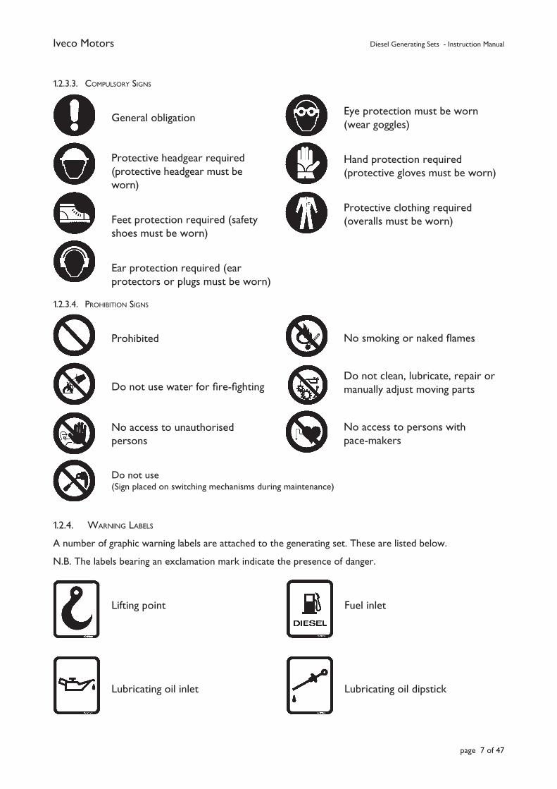
1.2.4. WARNING LABELS
A number of graphic warning labels are attached to the generating set. These are listed below.
N.B. The labels bearing an exclamation mark indicate the presence of danger.
1.2.3.3. COMPULSORY SIGNS
General obligation
Protective headgear required (protective headgear must be worn)
Feet protection required (safety shoes must be worn)
Ear protection required (ear protectors or plugs must be worn)
Do not use(Sign placed on switching mechanisms during maintenance)
Fuel inlet
Lubricating oil dipstick
Lifting point
Lubricating oil inlet
Iveco Motors Diesel Generating Sets - Instruction Manual
page 8 of 47
1.3. REFERENCE DOCUMENTS
The Operating Instructions supplied with each generating set consists of a collection of documents, of which this manual constitutes the General Part. In general, the following documents are supplied.
a) EC Conformity Declaration.
b) Standard technical data sheet for the set and its main components.
c) Iveco Motors Instruction Manual for Diesel Generating Sets - General (this manual).
d) Control panel wiring diagram (inserted in the control panel itself together with any specifi c manuals when required).
e) Iveco Motors Diesel Engine Operating and Maintenance Manual.
f) Operating and Maintenance manual issued by the generator Constructor.
g) Other manuals relating to optional accessories issued by the respective manufacturers.
h) List of Iveco Motors Service Centres (Service Network Booklet).
k) Starting Electric Generator sets.
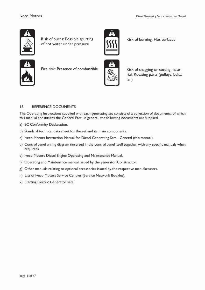
Risk of burns: Possible spurting of hot water under pressure
Fire risk: Presence of combustible
Risk of burning: Hot surfaces
Risk of snagging or cutting mate-rial: Rotating parts (pulleys, belts, fan)
Iveco Motors Diesel Generating Sets - Instruction Manual
page 9 of 47
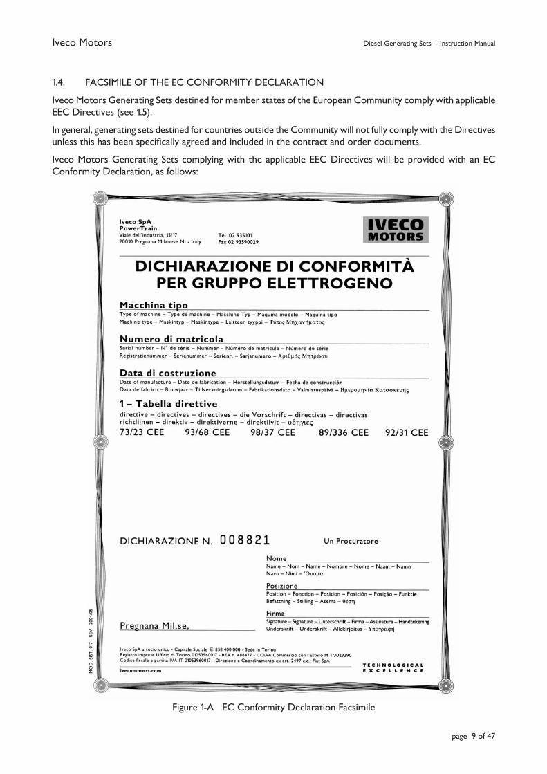
1.4. FACSIMILE OF THE EC CONFORMITY DECLARATION
Iveco Motors Generating Sets destined for member states of the European Community comply with applicable EEC Directives (see 1.5).
In general, generating sets destined for countries outside the Community will not fully comply with the Directives unless this has been specifi cally agreed and included in the contract and order documents.
Iveco Motors Generating Sets complying with the applicable EEC Directives will be provided with an EC Conformity Declaration, as follows:
Figure 1-A EC Conformity Declaration Facsimile
Iveco Motors Diesel Generating Sets - Instruction Manual
page 10 of 47
1.5. RELEVANT LEGISLATION
All Iveco Motors diesel generating sets are designed and manufactured in compliance with laws currently in force and are type approved, where required, by the principal Controlling and Certifi cation Bodies.
a) The electric generator set and its components are built to comply with the following applicable Directives and Standards:
73/23/CEE Low voltage.
89/336/CEE Electromagnetic compatibility.
93/68/CEE CE marking.
98/37/CEE Machine Directive.
2000/14/CEE Acoustic Emissions.
ISO 3046 Reciprocating internal combustion engines.
ISO 8528 RIC engine driven AC generator sets.
b) Synchronous generators used on Iveco Motors generating sets comply with the following standards:
IEC 34-1 / CEI 2-3 /VDE 0530 / BS 4999-5000 / NF 51-100.
They are also available with certifi cates issued by the following classifi cation bodies:
BUREAU VERITAS / DET NORSKE VERITAS / GERMANISCHER LLOYD / LLOYD’S REGISTER / RINA.
c) Any plant provided by the user, including its selection and construction criteria, must be in line with the Standards, Laws and Regulations in force in the country of installation and governing various aspects such as:
• noise;• emissions;• operation in hazardous environments;• limitations on installed power;• electrical plant and safety devices;• quantity of fuel present at the installation.
Iveco Motors Diesel Generating Sets - Instruction Manual
page 11 of 47
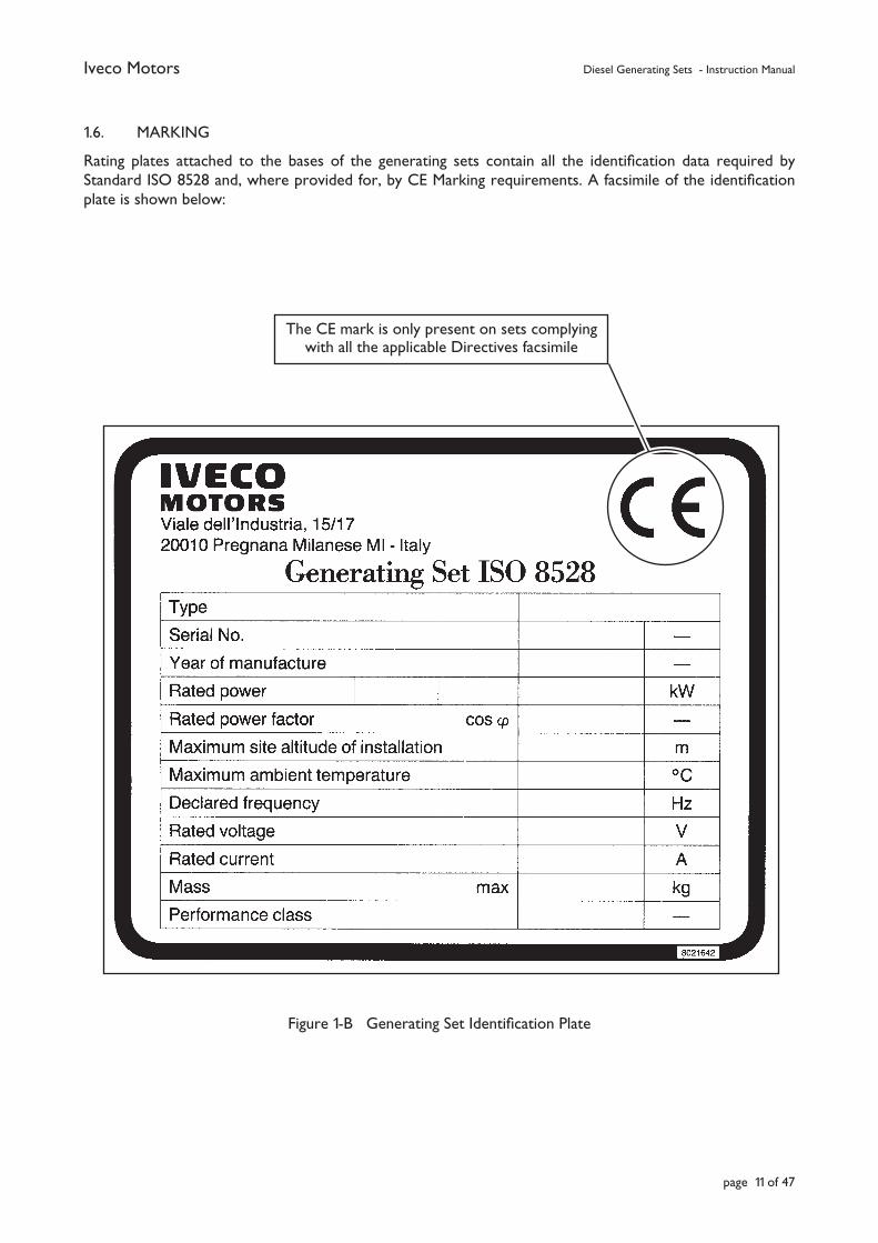
1.6. MARKING
Rating plates attached to the bases of the generating sets contain all the identifi cation data required by Standard ISO 8528 and, where provided for, by CE Marking requirements. A facsimile of the identifi cation plate is shown below:
Figure 1-B Generating Set Identifi cation Plate
The CE mark is only present on sets complyingwith all the applicable Directives facsimile
Iveco Motors Diesel Generating Sets - Instruction Manual
page 12 of 47
1.7. GUARANTEE
Any non-compliance with the installation requirements or the operating and maintenance standards specifi ed by Iveco Motors for the Generating Set and its components may render the guarantee null and void.
The guarantee period for the Generating Sets is specifi ed in the contractual documents.
The general guarantee conditions applicable to industrial products apply in this case also. Any claims for repairs under this guarantee must be made immediately to the offi cial Iveco Motors Dealer or Agency.
1.8. SPARE PARTS
For spare parts, refer exclusively to authorised spare part dealers or to the Iveco Motors Service Network.
In order to be able to correctly identify spare parts, always communicate the information reported on the rating plate fi xed to the base of the set, plus the type of motor and/or synchronous generator together with the relative serial numbers.
In order to be able to correctly identify the spare parts required, refer exclusively to the offi cial documentation supplied by Iveco Motors (Spare Parts Catalogue, Service Information, etc.).
Any other source of information not approved by Iveco Motors for its own applications may be misleading or incorrect.
Iveco Motors Diesel Generating Sets - Instruction Manual
page 13 of 47
2. OPERATING CONDITIONS AND LIMITS
2.1. GENERALThe infl uence of the factors described in this section must not be considered individually, but in combination with the effects produced by other factors.
2.2. ENVIRONMENTAL LIMITS
2.2.1. STANDARD ENVIRONMENTAL CONDITIONS
2.2.1.1. DIESEL ENGINES
Important: In accordance with Standard ISO 3046/1, the power ratings of diesel engines for stationary applications refer to the following environmental conditions:
- ambient temperature 25ºC;
- ambient pressure 1000 mbar (750 mm/Hg);
- relative humidity 30%.
2.2.1.2. SYNCHRONOUS GENERATORS
In accordance with standards IEC 34-1, ISO 8528-3 and CEI 2-3, the standard environmental conditions for synchronous generators for stationary applications are:
- ambient temperature 40ºC (30ºC acc. NEMA)
- altitude 1000 metres a.s.l (674 mm/Hg).
2.2.2. DERATING FOR ENVIRONMENTAL CONDITIONS
In the case of ambient installation and operating conditions that differ from the standard conditions reported in 2.2.1, the engine and the generator coupled to it must be derated to reduce the power output.
The effective prevalent environmental conditions in which the Generating Set will be installed must be clearly defi ned by the User/Client during the offer stage. Any derating, in fact, must be established as early as the contractual stage so that the engine and generator can be set-up from the start.
In particular, the User/Client must indicate the environmental conditions in which the Generating Set will operate, i.e.:
1. upper and lower ambient temperature limits;
2. height above sea level or, preferably, the maximum and minimum barometric pressure at the installation site. In the case of mobile sets, the minimum and maximum heights above sea level must be indicated;
3. humidity values in relation to temperature and pressure at the installation site, with particular attention to the relative humidity at maximum temperature;
4. maximum and minimum temperatures of cooling water for those sets equipped with water/water heat exchangers (specials available on request) as opposed to radiators;
5. any other particular environmental condition which may require the adoption of special measures or more frequent maintenance cycles such as:
• dusty or sandy atmospheres;
• marine type environments;
• environments with risk of chemical pollution;
• environments affected by radiation;
• operating conditions subjected to heavy stresses or vibration (e.g. seismic activity or external vibration generated by adjacent machinery).
Iveco Motors Diesel Generating Sets - Instruction Manual
page 14 of 47
In the case where the effective operating conditions are not specifi ed during the contractual stage, the power rating of the set will refer to the standard conditions for diesel engines reported in 2.2.1.1.
If the effective environmental conditions subsequently change, the Iveco Motors organisation should be informed in order that new derating calculations can be made and the machinery recalibrated.
For Diesel engines, refer to the engine documentation to determine these deratings.
The derating of synchronous generators is less critical that diesel engines. Therefore, the derating of the generating set generally coincides with that of the diesel engine.
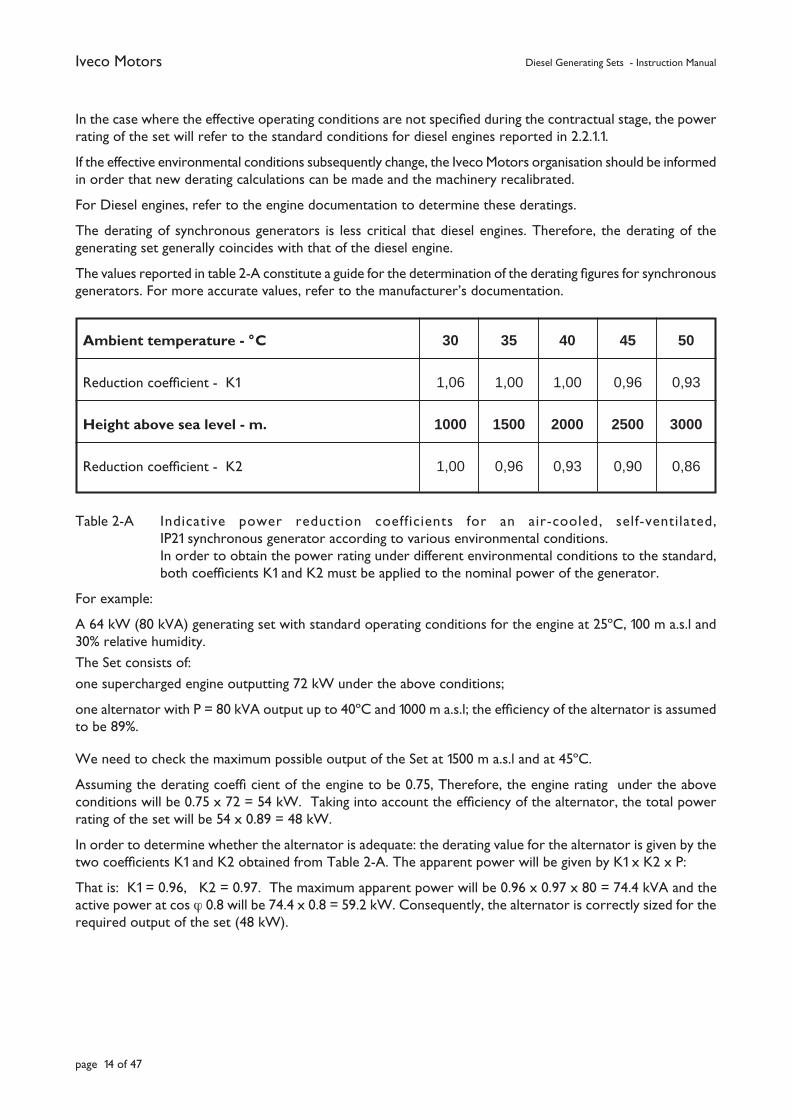
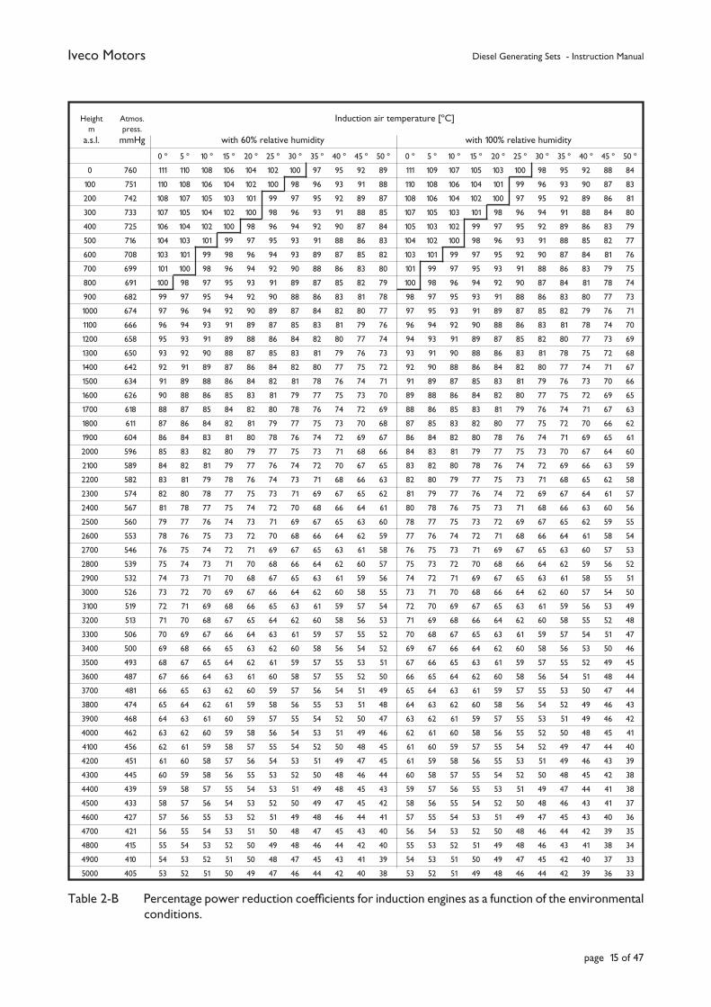
The values reported in table 2-A constitute a guide for the determination of the derating fi gures for synchronous generators. For more accurate values, refer to the manufacturer’s documentation.
Table 2-A Indicative power reduction coefficients for an air-cooled, self-ventilated, IP21 synchronous generator according to various environmental conditions. In order to obtain the power rating under different environmental conditions to the standard, both coeffi cients K1 and K2 must be applied to the nominal power of the generator.
For example:
A 64 kW (80 kVA) generating set with standard operating conditions for the engine at 25ºC, 100 m a.s.l and 30% relative humidity.
The Set consists of:
one supercharged engine outputting 72 kW under the above conditions;
one alternator with P = 80 kVA output up to 40ºC and 1000 m a.s.l; the effi ciency of the alternator is assumed to be 89%.
We need to check the maximum possible output of the Set at 1500 m a.s.l and at 45ºC.
Assuming the derating coeffi cient of the engine to be 0.75, Therefore, the engine rating under the above conditions will be 0.75 x 72 = 54 kW. Taking into account the effi ciency of the alternator, the total power rating of the set will be 54 x 0.89 = 48 kW.
In order to determine whether the alternator is adequate: the derating value for the alternator is given by the two coeffi cients K1 and K2 obtained from Table 2-A. The apparent power will be given by K1 x K2 x P:
That is: K1 = 0.96, K2 = 0.97. The maximum apparent power will be 0.96 x 0.97 x 80 = 74.4 kVA and the active power at cos ϕ 0.8 will be 74.4 x 0.8 = 59.2 kW. Consequently, the alternator is correctly sized for the required output of the set (48 kW).
Ambient temperature - °C 30 35 40 45 50
Reduction coeffi cient - K1 1,06 1,00 1,00 0,96 0,93
Height above sea level - m. 1000 1500 2000 2500 3000
Reduction coeffi cient - K2 1,00 0,96 0,93 0,90 0,86
Iveco Motors Diesel Generating Sets - Instruction Manual
page 15 of 47
Height Atmos.
Induction air temperature [ºC] m press. a.s.l. mmHg with 60% relative humidity with 100% relative humidity 0 º 5 º 10 º 15 º 20 º 25 º 30 º 35 º 40 º 45 º 50 º 0 º 5 º 10 º 15 º 20 º 25 º 30 º 35 º 40 º 45 º 50 º 0 760 111 110 108 106 104 102 100 97 95 92 89 111 109 107 105 103 100 98 95 92 88 84 100 751 110 108 106 104 102 100 98 96 93 91 88 110 108 106 104 101 99 96 93 90 87 83 200 742 108 107 105 103 101 99 97 95 92 89 87 108 106 104 102 100 97 95 92 89 86 81 300 733 107 105 104 102 100 98 96 93 91 88 85 107 105 103 101 98 96 94 91 88 84 80 400 725 106 104 102 100 98 96 94 92 90 87 84 105 103 102 99 97 95 92 89 86 83 79 500 716 104 103 101 99 97 95 93 91 88 86 83 104 102 100 98 96 93 91 88 85 82 77 600 708 103 101 99 98 96 94 93 89 87 85 82 103 101 99 97 95 92 90 87 84 81 76 700 699 101 100 98 96 94 92 90 88 86 83 80 101 99 97 95 93 91 88 86 83 79 75 800 691 100 98 97 95 93 91 89 87 85 82 79 100 98 96 94 92 90 87 84 81 78 74 900 682 99 97 95 94 92 90 88 86 83 81 78 98 97 95 93 91 88 86 83 80 77 73 1000 674 97 96 94 92 90 89 87 84 82 80 77 97 95 93 91 89 87 85 82 79 76 71 1100 666 96 94 93 91 89 87 85 83 81 79 76 96 94 92 90 88 86 83 81 78 74 70 1200 658 95 93 91 89 88 86 84 82 80 77 74 94 93 91 89 87 85 82 80 77 73 69 1300 650 93 92 90 88 87 85 83 81 79 76 73 93 91 90 88 86 83 81 78 75 72 68 1400 642 92 91 89 87 86 84 82 80 77 75 72 92 90 88 86 84 82 80 77 74 71 67 1500 634 91 89 88 86 84 82 81 78 76 74 71 91 89 87 85 83 81 79 76 73 70 66 1600 626 90 88 86 85 83 81 79 77 75 73 70 89 88 86 84 82 80 77 75 72 69 65 1700 618 88 87 85 84 82 80 78 76 74 72 69 88 86 85 83 81 79 76 74 71 67 63 1800 611 87 86 84 82 81 79 77 75 73 70 68 87 85 83 82 80 77 75 72 70 66 62 1900 604 86 84 83 81 80 78 76 74 72 69 67 86 84 82 80 78 76 74 71 69 65 61 2000 596 85 83 82 80 79 77 75 73 71 68 66 84 83 81 79 77 75 73 70 67 64 60 2100 589 84 82 81 79 77 76 74 72 70 67 65 83 82 80 78 76 74 72 69 66 63 59 2200 582 83 81 79 78 76 74 73 71 68 66 63 82 80 79 77 75 73 71 68 65 62 58 2300 574 82 80 78 77 75 73 71 69 67 65 62 81 79 77 76 74 72 69 67 64 61 57 2400 567 81 78 77 75 74 72 70 68 66 64 61 80 78 76 75 73 71 68 66 63 60 56 2500 560 79 77 76 74 73 71 69 67 65 63 60 78 77 75 73 72 69 67 65 62 59 55 2600 553 78 76 75 73 72 70 68 66 64 62 59 77 76 74 72 71 68 66 64 61 58 54 2700 546 76 75 74 72 71 69 67 65 63 61 58 76 75 73 71 69 67 65 63 60 57 53 2800 539 75 74 73 71 70 68 66 64 62 60 57 75 73 72 70 68 66 64 62 59 56 52 2900 532 74 73 71 70 68 67 65 63 61 59 56 74 72 71 69 67 65 63 61 58 55 51 3000 526 73 72 70 69 67 66 64 62 60 58 55 73 71 70 68 66 64 62 60 57 54 50 3100 519 72 71 69 68 66 65 63 61 59 57 54 72 70 69 67 65 63 61 59 56 53 49 3200 513 71 70 68 67 65 64 62 60 58 56 53 71 69 68 66 64 62 60 58 55 52 48 3300 506 70 69 67 66 64 63 61 59 57 55 52 70 68 67 65 63 61 59 57 54 51 47 3400 500 69 68 66 65 63 62 60 58 56 54 52 69 67 66 64 62 60 58 56 53 50 46 3500 493 68 67 65 64 62 61 59 57 55 53 51 67 66 65 63 61 59 57 55 52 49 45 3600 487 67 66 64 63 61 60 58 57 55 52 50 66 65 64 62 60 58 56 54 51 48 44 3700 481 66 65 63 62 60 59 57 56 54 51 49 65 64 63 61 59 57 55 53 50 47 44 3800 474 65 64 62 61 59 58 56 55 53 51 48 64 63 62 60 58 56 54 52 49 46 43 3900 468 64 63 61 60 59 57 55 54 52 50 47 63 62 61 59 57 55 53 51 49 46 42 4000 462 63 62 60 59 58 56 54 53 51 49 46 62 61 60 58 56 55 52 50 48 45 41 4100 456 62 61 59 58 57 55 54 52 50 48 45 61 60 59 57 55 54 52 49 47 44 40 4200 451 61 60 58 57 56 54 53 51 49 47 45 61 59 58 56 55 53 51 49 46 43 39 4300 445 60 59 58 56 55 53 52 50 48 46 44 60 58 57 55 54 52 50 48 45 42 38 4400 439 59 58 57 55 54 53 51 49 48 45 43 59 57 56 55 53 51 49 47 44 41 38 4500 433 58 57 56 54 53 52 50 49 47 45 42 58 56 55 54 52 50 48 46 43 41 37 4600 427 57 56 55 53 52 51 49 48 46 44 41 57 55 54 53 51 49 47 45 43 40 36 4700 421 56 55 54 53 51 50 48 47 45 43 40 56 54 53 52 50 48 46 44 42 39 35 4800 415 55 54 53 52 50 49 48 46 44 42 40 55 53 52 51 49 48 46 43 41 38 34 4900 410 54 53 52 51 50 48 47 45 43 41 39 54 53 51 50 49 47 45 42 40 37 33 5000 405 53 52 51 50 49 47 46 44 42 40 38 53 52 51 49 48 46 44 42 39 36 33
Table 2-B Percentage power reduction coeffi cients for induction engines as a function of the environmental conditions.
Iveco Motors Diesel Generating Sets - Instruction Manual
page 16 of 47
2.3. OPERATING LIMITS
2.3.1. GENERAL
During the offer request stage, the User/Client must communicate all the operating conditions which may infl uence the operation of the Generating Set. In addition to the environmental conditions reported in item 2.2, the information must also include the characteristics of the load to feed, i.e. power, voltage and power factor. Particular attention must be paid to the determination of the load insertion sequence in line with that illustrated in item 2.3.7.
2.3.2. POWER RATING
The power output of the electric generator sets is the apparent power, expressed in kVA, delivered at the generator terminals, at the nominal voltage and frequency and in the established environmental conditions (see also 2.2.1.1). The power ratings are in accordance with the provisions of Standard ISO 8528/1 and 3046/1. The relative defi nitions are reported below:
2.3.2.1. CONTINOUS POWER (COP/ISO 8528-1 PAR. 13.3.1)
This is the power that the generating set is capable of continuously outputting for an unlimited number of hours per year, between the maintenance intervals specifi ed by the manufacturer and under the predetermined environmental conditions (see also 2.2.1.1).
An overload of 10% is permissible for regulating purposes only (temporary loads and sudden load variations) and not for normal feeding to the users.
2.3.2.2. PRIME POWER (PRP/ISO 8528/1 PAR. 13.3.2)
This is the maximum power available for one cycle at variable power that the generating set is capable of generating for an unlimited number of hours, between the maintenance intervals specifi ed by the manufacturer and under the predetermined environmental conditions (see also 2.2.1.1). The mean power obtainable during a 24 hour period must not exceed 80% of the PRP.
An overload of 10% is permissible for regulating purposes only.
2.3.2.3. MAX STAND-BY POWER (ISO 3046 FUEL STOP POWER)
This is the maximum power available for use with variable loads for a limited number of hours per year (500 h), in the established environmental conditions (see also 2.2.1.1), with an average load factor of 90% of the declared stand-by power.
No overloads are allowed.
2.3.3. FREQUENCY
Iveco Motors generating sets are normally designed to operate at 1500 rpm and at 1800 rpm at a frequency of 50 Hz and 60 Hz respectively (4-pole generator).
The engines are fi tted with either a mechanical regulator or electronic control unit.
The mechanical rev regulator is incorporated within the injection pump, it is normally adjusted for a toleranceof 5% to enable a full load frequency of 50Hz and an off-load frequency of 52.5Hz.
Under stable conditions, the standard speed governor is generally accurate to within ± 0.5%.
These performance fi gures correspond to that provided for by Standard ISO 3046/IV - Class A1 and 8528-5 Class G2.
The engines with an electronic control unit operate asynchronously with accuracy of ±0.25%, complying with Standard 8528-5 Class G3/G4.

Iveco Motors Diesel Generating Sets - Instruction Manual
page 17 of 47
2.3.4. VOLTAGE
The generator voltage regulator is ELECTRONIC and is designed to check the voltage at the terminals as required by Standard 8528-5.
2.3.5. POWER FACTOR
As mentioned earlier, the power output of the electric generator sets is the Apparent power, expressed in kVA, delivered at the generator terminals. The nominal power factor is cos ϕ = 0.8; as a result, the Active Power will be 0.8 times the Apparent Power. The value of the Power Factor depends on the electrical characteristics of the load. Iveco Motors generating sets equipped with synchronous generators are capable of supplying both the active power and the reactive power requested by the load. However, while the active power is supplied by the diesel engine (transforming mechanical power into electrical power through the generator itself), the reactive power is supplied by the synchronous generator. Consequently, when considering operation at values other than cos ϕ = 0.8, the following aspects must be taken into account:
2.3.5.1. LOAD WITH COS ϕ BETWEEN 0.8 AND 1
At Nominal Active Power, the synchronous generator functions perfectly with cos ϕ values between 0.8 and 1.
2.3.5.2. LOAD WITH COS ϕ LESS THAN 0.8
With a given rating value, in relation to cos ϕ = 0.8, in a synchronous generator, the more the value of cos ϕ tends towards 0, the more the overload on the excitation system increases. In fact, the reactive power to output increases as cos ϕ decreases. The generator must, therefore, be derated according to the manufacturer’s instructions.
Under these conditions, the diesel engine is generally producing excess power.
Table 2-C shows an example of these derating coeffi cients. For more detailed information, refer to the generator constructor’s documentation.
Table 2-C Examples of generator power reduction coeffi cients as a function of cos ϕ.
2.3.6. SINGLE-PHASE LOAD
The generating sets can be loaded with unbalanced loads up to the maximum rated current in each phase.
This means that no more than ��
3/3 = 0,58
of the nominal three-phase power output of the set can
be inserted between two phases (for example, between L1 and L2). Similarly, no more than 1/3 (i.e. 33%) of the rated three-phase power can be inserted between one phase and neutral (for example, between L3 and neutral).
It must be remembered that during single-phase operation, or when the loads are unbalanced, the voltage tolerances described in 2.3.4 can no longer be maintained by the voltage regulator.
Power Factor - cos ϕ 1 0,8 0,7 0,6 0,5 0,3 0
Reduction coeffi cient 1,00 1,00 0,93 0,88 0,84 0,82 0,80
Iveco Motors Diesel Generating Sets - Instruction Manual
page 18 of 47
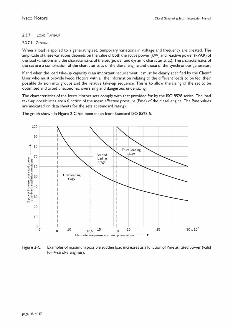
2.3.7. LOAD TAKE-UP
2.3.7.1. GENERAL
When a load is applied to a generating set, temporary variations in voltage and frequency are created. The amplitude of these variations depends on the value of both the active power (kW) and reactive power (kVAR) of the load variations and the characteristics of the set (power and dynamic characteristics). The characteristics of the set are a combination of the characteristics of the diesel engine and those of the synchronous generator.
If and when the load take-up capacity is an important requirement, it must be clearly specifi ed by the Client/User who must provide Iveco Motors with all the information relating to the different loads to be fed, their possible division into groups and the relative take-up sequence. This is to allow the sizing of the set to be optimised and avoid uneconomic oversizing and dangerous undersizing.
The characteristics of the Iveco Motors sets comply with that provided for by the ISO 8528 series. The load take-up possibilities are a function of the mean effective pressure (Pme) of the diesel engine. The Pme values are indicated on data sheets for the sets at standard ratings.
The graph shown in Figure 2-C has been taken from Standard ISO 8528-5.
Figure 2-C Examples of maximum possible sudden load increases as a function of Pme at rated power (valid for 4-stroke engines).
5 10 15 20 25 30 x 102
8 13,5 18
100
90
80
70
60
50
40
30
20
10
0
Pressione media effettiva Pme, alla potenza dichiarata, in kpa
Aum
ento
di p
oten
za r
iferit
o al
la p
oten
za d
ichi
arat
aal
le c
ondi
zion
i am
bien
te d
i ins
talla
zion
e, in
%
Primo stadiodi carico
Secondostadio
di carico
Terzo stadiodi carico
Mean effective pressure at rated power in kpa
% p
ower
incr
ease
ove
r ra
ted
pow
er
at a
mbi
ent
inst
alla
tion
cond
ition
s
Third loading stageSecond
loading stage
First loading stage
Iveco Motors Diesel Generating Sets - Instruction Manual
page 19 of 47
2.3.7.2. STARTING-UP ASYNCHRONOUS MOTORS
The start-up of asynchronous motors by a generating set presents a number of problems, in that the motors, in particular those with cage type rotors, have high pickup currents when starting (Istart = up to 8 times the nominal current (In) with low power factors.
Under these conditions, the current absorbed by the asynchronous motor (or by motors which start-up simultaneously) during start-up must not exceed the maximum current that the generator is able to provide in the short-term, with an acceptable voltage drop, nor must it exceed the overtemperature limits.
In order to prevent excessive oversizing of the generating set, the following solutions can be adopted:
a. In the case of several motors, divide them into groups which start-up according to a predetermined time sequence of between 30 - 60 seconds.
b. In the case of a single motor, if the coupled operating machine allows this to be done, adopt a reduced voltage start-up system (star/delta, autotransformer) or, for higher powers, use motors with wound rotors and rheostat starters.
In the case of star/delta start-up, the voltage on each phase is reduced and the start-up current (Istart) is
reduced in proportion ( to 1 / ��
3 = 0,58 ).
It thus becomes evident that, in the case of a motor with Istart = 6 In and with direct start-up, with star/delta starting, Istart reduces to ~ 3.5 In, with the result that the generating set needs to deliver less power in the ratio of 6/3/5.
In all cases, whether with direct start-up or reduced voltage start-up, the equipment and users connected to the user circuit must be checked to prevent problems (e.g. contactors opening) caused by transitory voltage drops at pick-up.
2.4. IMPROPER USE
The Generating Set you have bought is designed to be used for the production of electricity under the conditions and within the operational and environmental limits expressed in items 2.2 and 2.3, or under the conditions and within the limits otherwise agreed in the contract. Iveco Motors must be informed of any changes in these conditions or limits, either directly or via authorised service centres, in order that the necessary approval can be given and, if necessary, any modifi cations and/or recalibration work required to the set can be done.
The Generating Set is a machine which transforms potential heat energy contained in the fuel into electricity. The set is destined to feed distribution plant manufactured according to the relevant specifi cations by specialist personnel. Even though the amount of power involved is substantially less than that supplied by a public grid system (mains), the hazardous nature of electricity remains unaltered. In fact, a generating set not only produces electricity, with its inherent dangers, but also has additional hazards caused by the presence of combustible materials (the fuel used and the lubricating oils involved), rotating machinery and secondary waste products (exhaust gas, heat from the cooling system and irradiation).
Even though it may be possible to make use of the heat contained in the exhaust gases and cooling circuit, and thereby increase the effi ciency of the generating process, any such operation must be performed by specialised personnel in order to obtain a reliable and safe plant and to avoid jeopardising the guarantee.
Unless previously agreed with Iveco Motors, any use other than that specifi ed will be considered as improper, and as such not permissible.
Iveco Motors Diesel Generating Sets - Instruction Manual
page 20 of 47
2.5. MODIFICATIONS TO OPERATING DATA
2.5.1. FREQUENCY CHANGE
Iveco Motors generating sets are normally supplied with speed governors fi tted to the engine for operation at 50 Hz (1500 rpm) or at 60 Hz (1800 rpm).
With regard to the instrument panel, it should be noted that:
• automatic control unit panels are already set-up for dual frequency.
• in the case of control boards for manual units, the switches are not always calibrated to bear the increase in power at the same voltage due to the increase from 50 to 60 Hz; this must be verifi ed in advance before connection to the supply cables.
It is possible, nevertheless, to change from 60 Hz to 50 Hz on a set originally supplied for operation at 60 Hz.
To change the frequency of a non electronically controlled pump, it is necessary either to have the injection pump re-calibrated by a member of the Iveco Motors organisation, or to regulate the revs by adjusting the accelerator lever; to change the frequency of an electronic unit requires a simple adjustment..
The voltage output from the generator must also be calibrated to the required operating value.
It should be remembered that if the output voltage is not recalibrated, the increase in frequency will result in a proportional increase in the output voltage itself.
For example, switching from 50 Hz to 60 Hz will result in an increase in the output voltage from 400 V to 440 V.
In order to be able to output 400 V at 60 Hz, refer to an authorised service centre who will check whether this particular changeover is possible.
When modifying frequencies, it should be remembered that:
• the changeover from 50 to 60 Hz produces a slight increase in power output. This can be seen in the Iveco Motors Data Sheets for the sets;
• the changeover from 60 to 50 Hz produces a reduction in power output;
• the nominal voltage can be calibrated by adjusting the control rheostat;
• frequency: check that the frequency meter has been adjusted to operate at the new frequency.
2.5.2. VOLTAGE CHANGE
The operating voltage of generators with 12 wire terminal boards can be varied by following the manufacturer’s instructions in the generator manual.
Warning: a variation in voltage at a given power rating will result an inversely propor-tional variation in the current. Therefore, check that the rated capacity of the electrical equipment downstream can support the new current and/or provide the plant with a suitable protection system.
2.6. TYPES OF OPERATION
Iveco Motors generating sets are designed for use as either manually controlled or automatically controlled units.
Switching from one service type to another requires the replacement of the control panel (a simple procedure, in that the auxiliary services are installed via connectors) and, when switching to the automatic version, the installation of the water pre-heater.
The engine wiring is already set-up for these connections.
Iveco Motors Diesel Generating Sets - Instruction Manual
page 21 of 47
3. SAFETY
3.1. GENERAL
Before starting the Electric Generator set and before any lubrication or maintenance operation, it is essential that the personnel responsible must have read and understood all the WARNINGS AND CAUTIONARY NOTICES contained in the leafl et “START-UP OF THE ELECTRIC GENERATOR SETS”.
The constructor, however, cannot foresee all the possible circumstances which may lead to possible risk during the actual operation of the generating set.
Any maintenance operations or procedures not strictly provided for in the operating manual must be reported to the constructor beforehand for approval.
When the need arises to follow a procedure which has not been specifi cally recommended, the user will be responsible for ensuring that said procedure is safe and does not lead to damage or injury.
The following instructions mut be followed closely to ensure safe operation.
3.2. ACCESS TO THE PLANT
Rooms or areas in which a generating set is installed are to be considered as an Electricity Production Shop (see 1.2.2.1). As such, the installed plant must be managed exclusively by specialised and suitable trained personnel.
Access must not be allowed to unauthorised persons.
Access is denied to persons wearing a pace-maker, due to possible electromagnetic interference to cardio-stimulation equipment.
In the case of automatic start-up sets:
• install a red light in a clearly visible position which lights-up when the set is operating;
• provide a sign warning of the danger of sudden automatic start-up of the machine;
• provide a sign stating that ”All maintenance operations must be carried out with the set shut-down”.
If the set needs to be stopped in an emergency, press the “emergency stop” button located on the panel or (when provided) the stop button positioned outside the generator room.
3.3. SAFETY REQUIREMENTS DURING INSTALLATION AND COMMISSIONING
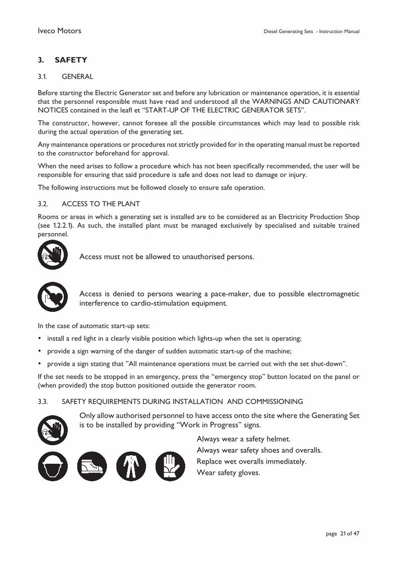
Only allow authorised personnel to have access onto the site where the Generating Set is to be installed by providing “Work in Progress” signs.
Always wear a safety helmet.Always wear safety shoes and overalls.Replace wet overalls immediately.Wear safety gloves.
Iveco Motors Diesel Generating Sets - Instruction Manual
page 22 of 47
Do not remove protection devices mounted over moving parts, hot surfaces, air intakes, drive belts or live components.
Do not leave dismantled components or tools on the engine, or any other equipment not forming part of the plant in the same room or area occupied by the Generating Set.
Never leave fl ammable liquids or rags soaked in fl ammable substances near to the generating set, electrical equipment (including lamps) or electrical parts.
Every possible precaution must be taken to prevent electrocution. Check that the earthing system is connected and according to standard.
Affi x a sign “DO NOT OPERATE” on all switching devices isolating the parts on which maintenance is to be carried out. Whenever possible, use key operated locking devices to prevent accidental or dangerous manoeuvres.
• Install the necessary safety devices on the outer parts of the plant.
• Insulate all connections and loose wires. Do not leave the power terminal box on the generator open.
• Inspect and check that the electrical power connections and auxiliary service connections have been correctly made.
• Ensure that the phase cyclic direction of the generator agrees with that of the mains.
• Check that the devices for stopping the set function correctly. In particular, check the overspeed shutdown device (if fi tted), the low oil pressure and high engine water temperature devices and the emergency stop button installed by the user outside the generating room.
• Check that the ventilation of the room in which the Generating Set is installed is correctly ventilated. Check that the engine exhaust is unobstructed and that the exhaust piping evacuates the gas correctly. Also check that the exhaust pipe and silencers are adequately supported, fi tted with expansion joints and protected against accidental contact.
• Check that the exhaust gases are discharged to atmosphere outdoors at a safe location, away from doors, windows and air intakes.
• Check the oil pipes and fuel lines (diesel oil) and ensure that there are no leaks.
Preliminary safety checks
Prior to initiating any start-up procedure, it is of extreme importance to familiarise oneself with the generating set and with the plant. A visual inspection must also be carried out with regard to the safety aspects of the machine’s work station and its installation. This inspection must include all the items listed below and any other which may be of importance for the installation. Any source of danger, actual or potential, must be eliminated prior to proceeding.
1. Identify the positions of the emergency stop buttons, emergency fuel shut-off valves, switches and any other emergency shut-down systems on the plant
2. Be aware of any special emergency procedures appertaining to the installation in question
3. Identify the positions of the fi re extinguishers and any other safety or emergency equipment and know how to use them
4. Identify any possible source of danger, such as fuel leaks, lubricating oil leaks, acid spills, condensate in the drip feeds, high voltages, high pressures, and other dangers.
5. Ensure that the set is clean, that the surrounding area and emergency exits are clean and free of any obstructions. Check that none of the inlet openings or breathers are blocked.
Iveco Motors Diesel Generating Sets - Instruction Manual
page 23 of 47
6. Check whether people are working on other equipment in the zone and whether the work is dangerous or prevents the plant from operating.
Never start the set if it is not in a condition of maximum safety.
3.4. SAFETY REQUIREMENTS DURING MAINTENANCE
3.4.1. GENERAL PRECAUTIONS
Do not allow unauthorised access to zones in which maintenance work is being carried out by fi xing the “Work in Progress” sign.
Place a “DO NOT OPERATE” sign on all switchgear isolating the parts of the plant on which work is to be carried out. Whenever possible, use a key operated lock to prevent undesirable or dangerous manoeuvres.
Never wear loose clothing, rings or chains when working near to moving parts or motors.
Use safety gloves and goggles:• during battery maintenance;• when topping-up inhibitors or antifreeze;• when changing or topping-up lubricating oil (hot engine oil can cause burns
when being drained. Allow it to cool to below 60ºC);• when using compressed air (in this case, the maximum pressure for cleaning
purposes must be less than 2 atm (30 psi, 2 kg/cm2)).
Use a safety helmet when working in an area with suspended loads or with plant located at head height.
Always wear safety shoes and overalls.
When working on parts which may become live, always keep hands and feet dry. Where necessary, carry out operations using an insulated footboard. In all cases, if insuffi ciently experienced in this type of work, call specialised personnel to perform the operations or adjustments.
Replace wet overalls immediately.
Use a barrier cream on hands.
Replace used rags in a fl ameproof container.
Never leave rags on the engine.
Keep used oil in a suitable safe container.
Iveco Motors Diesel Generating Sets - Instruction Manual
page 24 of 47
Do not attempt to carry out repairs that are unfamiliar. Always follow the instructions; if instructions are not available, contact the supplier or qualifi ed personnel.
When starting the engine after repairs have been carried out, take suitable measures to enable the air intake to be shut-off if the machine starts out of synch.
Always keep the engine clean, removing any oil, diesel or cooling liquid spills.
Never start the engine with the speed governor lever disconnected.
Work requiring two or more persons must not be carried out by one man, especially when performing operations on moving parts such as switches, fuses or other live equipment.
3.4.2. ENGINE COOLING CIRCUIT
• Never add coolant to a hot engine; allow the engine to cool down fi rst.
• Periodically check the level of cooling liquid and top-up if necessary. Use the correct fl uid as specifi ed in the engine operating and maintenance manual.
Remove the radiator cap slowly. Cooling circuits normally operate under pressure and any hot liquid may spurt out if the pressure is released too quickly.
• Periodically check the tension and degree of wear in the pump/fan drive belt.
3.4.3. LUBRICATING CIRCUIT
• Periodically check the oil level in the sump with the engine cold. Top-up if necessary in line with the instructions reported in the engine operating and maintenance manual.
Do not smoke or use naked fl ames when topping-up the oil.
3.4.4. FUEL CIRCUIT
Do not smoke or use naked fl ames when refuelling.
3.4.5. EXHAUST CIRCUIT
Carry out a visual check of the exhaust system and identify any exhaust gas leaks. Carry out any necessary repairs immediately; exhaust gas is a source of danger and a fi re hazard.
Warning: very hot surfaces. The parts of the plant pre-assembled in the factory are protected against accidental contact. Installation components such as ducts conveying exhaust gas from the building, silencers supplied separately, etc. must be insulated and/or protected by the installer.
3.4.6. ELECTRIC START SYSTEM
Disconnect the negative pole from the battery before working on the engine. This is to prevent accidental starting. Ensure that the engine’s automatic start-up system does not come into operation and start the engine while work is being carried out on it.
Iveco Motors Diesel Generating Sets - Instruction Manual
page 25 of 47
• Make sure that all connections are tight and check that the insulation on the wires is in a good condition.
When batteries are being recharged, a potentially explosive gas is emitted. The room, therefore, must be well ventilated and naked flames or smoking not allowed in the vicinity of the batteries.
In order to prevent the arcing, it is advisable to connect the positive terminal to the battery first, and then the negative (normally earth).
3.4.7. SYNCHRONOUS GENERATORS
Do not carry out any maintenance while the generating sets are running. Before carrying out any work, ensure that the set is SHUT-DOWN and cannot restart.
Clean the air intakes on the generators ventilation system and, on some models, lubricate the bearings. In particular, check the tightness and positions of the electrical connections.
3.4.8. ELECTRIC PANEL
Before carrying out any work on the electric panel, disconnect the unit from the mains power supply and SHUT-DOWN the system.
As with all electric equipment, the electric panels are particularly sensitive to humidity and dust. Consequently, ensure that the anti-condensation heaters are working correctly and, when fi tted, clean the ventilation air intake.
Periodically check the tightness of the electrical connection bolts.
3.5. DURING OPERATION
Allow authorised operating staff only to have access to the Generating Set installation by affi xing the appropriate signs.
Never wear loose clothing, rings or chains when working near to motors or moving parts.
In order to prevent damage to the hearing, always wear ear protectors when spending any length of time in the room while the Generating Set is in operation.
Do not touch the generating set, in particular the wiring or connections to the alternator while it is turning; it is live. Periodically check all the connections, both with regard to tightness and insulation.
Never leave fl ammable liquids or rags soaked in fl ammable liquid near to the set, near to electrical equipment (including lamps) or electrical parts of the plant.
Iveco Motors Diesel Generating Sets - Instruction Manual
page 26 of 47
4. DESCRIPTION OF THE MACHINE
4.1. GENERAL
Diesel generating sets are independent complexes used for the generation of electricity. Basically they consist of a synchronous constant voltage electric generator driven by an internal combustion diesel engine.
The sets are used for two principal types of service:
a) Sets for normal service
Used for the production of electricity for a multitude of uses (motive power, lighting, heating, etc.) in an area where there are no other electricity sources.
b) Sets for emergency service
Used to meet electricity demands in the case of an interruption in the mains supply, when said interruption could create serious problems for persons or cause material or fi nancial damage (hospitals, continuous cycle industrial plants, etc.), or help meet demand during peak consumption periods.
Depending on their location, generating sets are divided into:
• land use;
• marine applications (on-board sets).
Land use sets are divided into two types:
• stationary sets (fi xed installation);
• mobile sets (mobile installation).
These two type are, in turn, further divided into a vast range of types according to their operating methods, i.e.:
1. manual start-up;
2. automatic start-up.
4.1.1. SPECIAL APPLICATIONS
4.1.1.1. SETS CONNECTED IN PARALLEL
In order to obtain greater operating power, two or more sets can be connected in parallel.
The requirements to observe for each set are reported in this manual, while the specifi cations for the control panels, which vary according to the paralleling, are reported in the manuals supplied with the panels.
4.1.2. ON-BOARD SETS
(Excluded from the range of applications provided for by Machinery Directive - 89/392/CEE and subsequent amendments).
Even though this manual has been prepared specifi cally for land sets, the following paragraphs provide information which is also relevant to on-board generating sets, in that many of the maintenance and safety requirements are applicable to both types of application.
Iveco Motors Diesel Generating Sets - Instruction Manual
page 27 of 47
On-board sets can be divided into two distinct categories:
a) Primary service sets, destined for the production of electricity for on-board services (on passenger ships, cargo ships, ferries, tugs, platforms, etc.).
Marine engines are normally used for these types of sets and have closed-circuit fresh-water cooling systems and fresh water/sea water heat exchangers for keel cooling.
b) Emergency generating sets which cut-in automatically to feed essential services when the auxiliary sets shut-down.
These sets are located in the upper parts of the vessel. The engines are derived from industrial engines and are equipped with radiator type cooling.
Refer to specifi c commercial documentation for the characteristic data of the entire range.
4.1.2.1. TESTING
Sets used for marine installations must comply with the standards and tests provided for by the Marine Classifi cation Body chosen by the shipyard.
4.1.2.2. MISCELLANEOUS INFORMATION
The information on exhaust pipes, room ventilation and exhaust silencers provided for land-based sets is also valid for marine applications. The start-up and maintenance procedures are also similar. For further information and/or connections (e.g. cooling circuit, fuel lines, etc.) on marine engines, refer to the Iveco Motors marine engine installation manual.
Special attention must be paid to electrical connecting wires, in that their insulation and cross-section must comply with the provisions of the various Marine Classifi cation Bodies.
4.2. COMPOSITION OF STANDARD IVECO MOTORS GENERATING SETS
A standard stationary generating set generally consists of:
• diesel engine;
• synchronous generator;
• fl ex-plate coupling joint;
• steel chassis with vibration-proof supports, starter batteries and auxiliary services;
• fuel tank incorporated in the base;
• control panel (on request);
• exhaust silencers (on request);
A detailed description of the set and its components is reported on the relevant data sheet.
Iveco Motors Diesel Generating Sets - Instruction Manual
page 28 of 47
5. TRANSPORT AND HANDLING
All transport and handling activities must be carried out by organisations of proven experience in the transport and handling of machinery and industrial equipment. These organisations must employ specialised personnel and use the appropriate equipment in line with the dimensions and weight of the package and the logistics of the sites.
Do not use the lifting eyes of the individual components (engine, alternator) to lift the entire Generating Set, in that they are not designed to take the overall weight of the Generating Set.
Do not allow personnel to stand near to the Generating Set during the lifting and handling operations.
Safety helmets, gloves and safety shoes must be worn during unloading and handling operations.
Cranes, overhead gantries and lift trucks can be used for unloading, handling and positioning the generating set. Ensure that the available equipment is of suitable capacity for the weight of the set to be moved and the characteristics of the site.
The weights of the generating sets are reported on the data sheets.
Check that the dimensions of the set are compatible with the sizes of the openings through which it will pass during its journey. The lifting means must be operated by qualifi ed, trained and authorised personnel only.
Loads must be lifted vertically without oscillation.
Do not:
• lift obliquely;
• jerk anchored parts;
• leave loads suspended even for short periods of time;
• lift or transport personnel using lifting devices designed for materials.
When performing handling operations, the loads must be kept as close to the ground as possible and must not be transported over work stations or passage ways, unless suitable measures have been taken to prevent people standing along the route.
Check that all lifting equipment and associated safety devices are in perfect working order before using them (limit switches, brakes, signalling devices, etc.).
The slinging of the loads must be carried out by qualifi ed and trained personnel.
It is advisable to use the slings provided by specialised companies who are able to guarantee the indicated capacity.
The stresses on the individual cables of a sling must vary according to the shape of the load, the position of its barycentre and the oscillations occurring during movement. In particular, the stress on the cables increases as the internal angle between the cables at the apex increases. Under normal circumstances, this angle must not be greater than 60º and, under no circumstances, must it be greater than 120º (it is, nevertheless, not advisable to exceed 90º). In this case, use longer slings or, even better, spreader bars.
The capacity of the cables must therefore be checked in accordance with the selected lifting angle.
Cables and chains must be protected against contact with any sharp corners on the load.
Hooks must be fi tted with safety closing devices and must bear the maximum allowed capacity. If this capacity is different to that of the lifting equipment to which it is attached and the cables used, then the weight which can be lifted must not exceed the least of these capacities.
Iveco Motors Diesel Generating Sets - Instruction Manual
page 29 of 47
Spreader beams or other hook-up devices reduce the forces on the cables, thus reducing their inclination and increasing the stability of the load, provided that they have been designed by a qualifi ed engineer for the type of load to lift.
Special attention must be paid to the position of the barycentre of the load.
5.1. USING STATIONARY, MOBILE OR BRIDGE CRANES
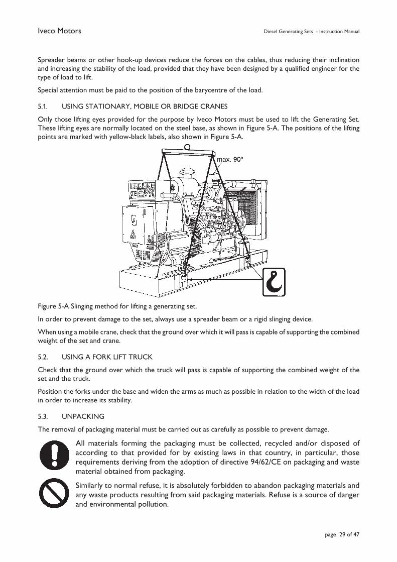
Only those lifting eyes provided for the purpose by Iveco Motors must be used to lift the Generating Set. These lifting eyes are normally located on the steel base, as shown in Figure 5-A. The positions of the lifting points are marked with yellow-black labels, also shown in Figure 5-A.
Figure 5-A Slinging method for lifting a generating set.
In order to prevent damage to the set, always use a spreader beam or a rigid slinging device.
When using a mobile crane, check that the ground over which it will pass is capable of supporting the combined weight of the set and crane.
5.2. USING A FORK LIFT TRUCK
Check that the ground over which the truck will pass is capable of supporting the combined weight of the set and the truck.
Position the forks under the base and widen the arms as much as possible in relation to the width of the load in order to increase its stability.
5.3. UNPACKING
The removal of packaging material must be carried out as carefully as possible to prevent damage.
All materials forming the packaging must be collected, recycled and/or disposed of according to that provided for by existing laws in that country, in particular, those requirements deriving from the adoption of directive 94/62/CE on packaging and waste material obtained from packaging.
Similarly to normal refuse, it is absolutely forbidden to abandon packaging materials and any waste products resulting from said packaging materials. Refuse is a source of danger and environmental pollution.
Iveco Motors Diesel Generating Sets - Instruction Manual
page 30 of 47
6. INSTALLATION
6.1. GENERAL INSTALLATION CRITERIA
The installation of one or more Generating Sets must be designed by specialised engineers qualifi ed for the design of this type of plant.
The installation must be carried out by qualifi ed organisations employing specialised personnel and using suitable equipment.
The installation must be carried out in line with current working practices, and the installer must, on completion of the installation, issue the Client with a Declaration of Conformity of the plant with the design and reference standards.
The following basic criteria must be taken into account for the installation:
a) Correct selection of the set in relation to the electrical load requirements and the environmental operating conditions (temperature, altitude, humidity) of the site.
b) The Generator Room, if the set is installed in an enclosed environment, must be suitably sized to allow good accessibility to the engine and to the generator for ordinary maintenance operations and repair works.
c) Again, when installed in an enclosed environment, provision must be made for the intake of a suitable quantity of air necessary for combustion in the engine, for cooling (radiator and generator) the set, and for ventilating the room (clean and fresh).
d) Correct use of fuels and lubricants.
e) Careful attention to problems linked to the safety of supervision personnel or operators.
f) Careful attention to problems linked to noise emission.
6.2. IMPORTANT INFORMATION
6.2.1. INSPECTION OF MATERIALS
On receiving the set, it is advisable to check that the materials correspond to that listed on the delivery note accompanying the shipment. Some of the packages may be opened at random to check that no damage has occurred during transit.
If damage is noted, the carrier must be informed immediately to enable the relevant claims procedure to be started.
6.2.2. PRELIMINARY INSTALLATION PROCEDURES FOR AUTOMATIC GENERATING SETS
In order to prevent undesired start-ups of automatic sets while carrying out preliminary installation operations and when making electrical connections, the following requirements must be respected:
• the starter batteries must be disconnected form the set;
• the operation selector on the control panel must be in the “OFF” position.
6.2.3. SAFETY STANDARDS FOR DIESEL ENGINES
The location and installation of the generating set (foundations, fuel tank, air intake, gas exhaust) must comply with the “Safety Standards” in force in the country of installation.
Iveco Motors Diesel Generating Sets - Instruction Manual
page 31 of 47
6.3. INSTALLATION
There are two types of installations for stationary generating stets:
a. outdoor installations;
b. indoor installations.
N.B.: The instructions that follow are necessary for the correct installation of the generating set, and remain valid unless otherwise provided for by the more rigid requirements of safety standards and other plant regulations (fi re department, local authority, nuclear standards, etc.) in force in the country of installation.
6.3.1. OUTDOOR INSTALLATIONS
Sets installed outdoors (excluding those housed in cabins or containers for which they have been specifi cally designed) must be protected against atmospheric agents such as rain, dust, etc. and must not be located in direct sunlight, as this may cause overheating. One possible solution to this may be to construct a roof over the set.
For temporary short-term installations, the sets need only be installed on level ground. For longer installation periods, the sets should be mounted on concrete foundations (see also 6.3.2.1).
The area in which the generating Set is to be installed must be suitably fenced-off to prevent access by unauthorised persons. No entry signs and warnings of the possible dangers must be affi xed to the fencing similarly to that provided for indoor installations (see item 3. - Safety Requirements).
6.3.2. INDOOR INSTALLATIONS
The installation of indoor sets must comply with the following requirements:• Suitably sized room to enable normal operation of the set with easy access to components for ordinary
maintenance and eventual repair works. Figure 6-A shows typical solutions for manual and automatic start-up sets. The fi gure also shows the minimum recommended dimensions for working space around the set and height
of the building. The size of the room must take into account the dimensions of the sets reported on the data sheets.
• Access to the rooms must be such to allow the entire set to be transported by normal transport and handling vehicles generally available on site.
• Openings must be of a suitable size to allow an effi cient air change to be effected. • The exhaust system must be such that the exhaust gas travels the shortest possible distance and through
the minimum number of bends.• The set should be arranged with suffi cient space on a minimum of three sides to facilitate access and comply
with safety standards (as shown in Figure 6-A).• The control panel (in the case of automatic sets) should be located in a position that allows an operator
working on the set to have an unobstructed view of the instruments.The basic factors to consider in line with the above requirements are:• foundations;• ventilation exhaust system;• fuel system;• electrical connections;• earthing system;• heating.
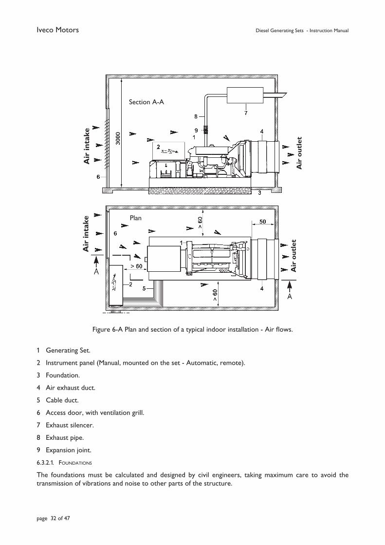
Iveco Motors Diesel Generating Sets - Instruction Manual
page 32 of 47
Figure 6-A Plan and section of a typical indoor installation - Air fl ows.
1 Generating Set.
2 Instrument panel (Manual, mounted on the set - Automatic, remote).
3 Foundation.
4 Air exhaust duct.
5 Cable duct.
6 Access door, with ventilation grill.
7 Exhaust silencer.
8 Exhaust pipe.
9 Expansion joint.
6.3.2.1. FOUNDATIONS
The foundations must be calculated and designed by civil engineers, taking maximum care to avoid the transmission of vibrations and noise to other parts of the structure.
Air
inta
keA
ir in
take
Section A-A
Plan
Air
ou
tlet
Air
ou
tlet
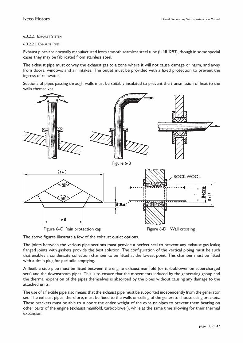
Iveco Motors Diesel Generating Sets - Instruction Manual
page 33 of 47
6.3.2.2. EXHAUST SYSTEM
6.3.2.2.1. EXHAUST PIPES
Exhaust pipes are normally manufactured from smooth seamless steel tube (UNI 1293), though in some special cases they may be fabricated from stainless steel.
The exhaust pipe must convey the exhaust gas to a zone where it will not cause damage or harm, and away from doors, windows and air intakes. The outlet must be provided with a fi xed protection to prevent the ingress of rainwater.
Sections of pipes passing through walls must be suitably insulated to prevent the transmission of heat to the walls themselves.
Figure 6-B
Figure 6-C Rain protection cap Figure 6-D Wall crossing
The above fi gures illustrate a few of the exhaust outlet options.
The joints between the various pipe sections must provide a perfect seal to prevent any exhaust gas leaks; fl anged joints with gaskets provide the best solution. The confi guration of the vertical piping must be such that enables a condensate collection chamber to be fi tted at the lowest point. This chamber must be fi tted with a drain plug for periodic emptying.
A fl exible stub pipe must be fi tted between the engine exhaust manifold (or turboblower on supercharged sets) and the downstream pipes. This is to ensure that the movements induced by the generating group and the thermal expansion of the pipes themselves is absorbed by the pipes without causing any damage to the attached units.
The use of a fl exible pipe also means that the exhaust pipe must be supported independently from the generator set. The exhaust pipes, therefore, must be fi xed to the walls or ceiling of the generator house using brackets. These brackets must be able to support the entire weight of the exhaust pipes to prevent them bearing on other parts of the engine (exhaust manifold, turboblower), while at the same time allowing for their thermal expansion.
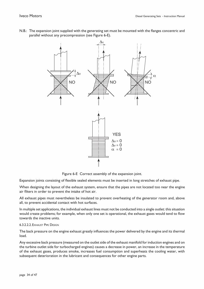
Iveco Motors Diesel Generating Sets - Instruction Manual
page 34 of 47
N.B.: The expansion joint supplied with the generating set must be mounted with the fl anges concentric and parallel without any precompression (see Figure 6-E).
Figure 6-E Correct assembly of the expansion joint.
Expansion joints consisting of fl exible sealed elements must be inserted in long stretches of exhaust pipe.
When designing the layout of the exhaust system, ensure that the pipes are not located too near the engine air fi lters in order to prevent the intake of hot air.
All exhaust pipes must nevertheless be insulated to prevent overheating of the generator room and, above all, to prevent accidental contact with hot surfaces.
In multiple set applications, the individual exhaust lines must not be conducted into a single outlet: this situation would create problems; for example, when only one set is operational, the exhaust gases would tend to fl ow towards the inactive units.
6.3.2.2.2. EXHAUST PIPE DESIGN
The back pressure on the engine exhaust greatly infl uences the power delivered by the engine and its thermal load.
Any excessive back pressure (measured on the outlet side of the exhaust manifold for induction engines and on the turbine outlet side for turbocharged engines) causes a decrease in power, an increase in the temperature of the exhaust gases, produces smoke, increases fuel consumption and superheats the cooling water, with subsequent deterioration in the lubricant and consequences for other engine parts.
∆o
NO
∆v
NO
α
NO
∆o = 0∆v = 0α = 0
SI
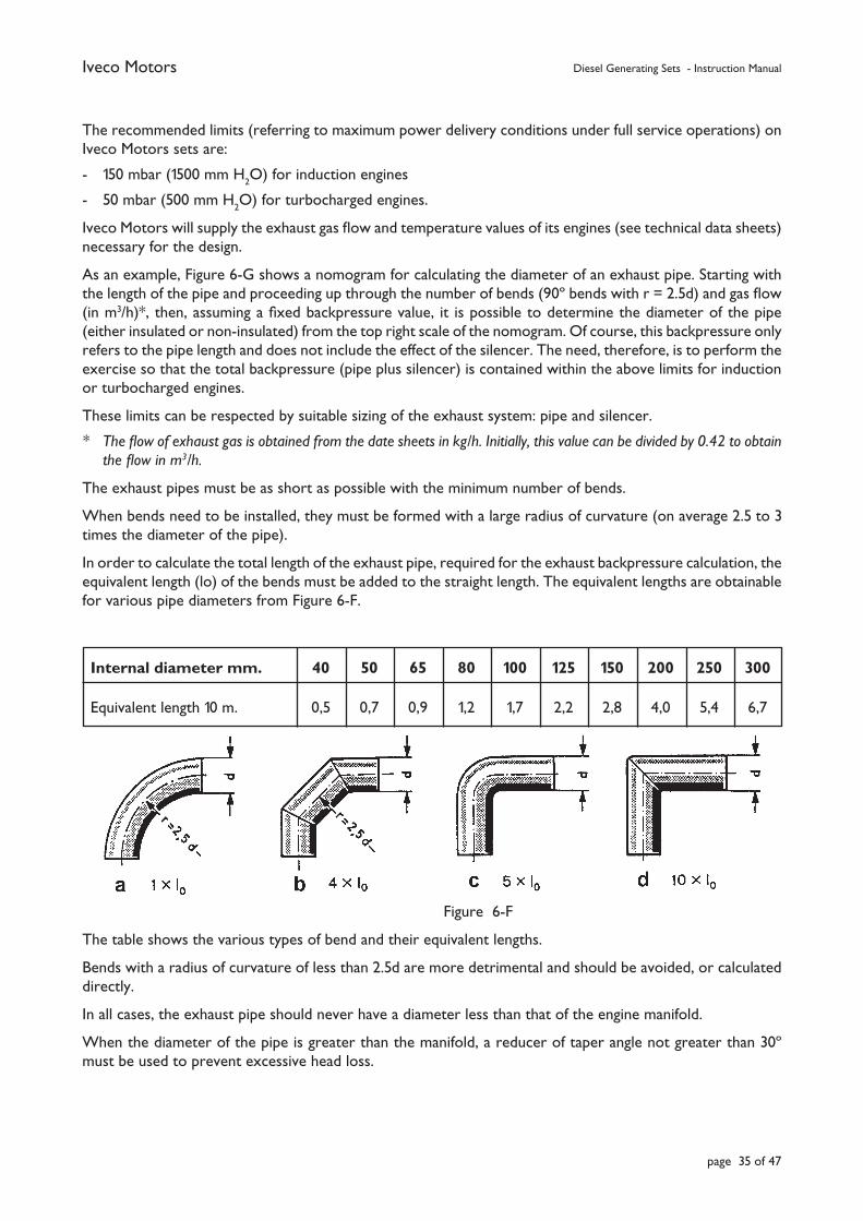
Iveco Motors Diesel Generating Sets - Instruction Manual
page 35 of 47
The recommended limits (referring to maximum power delivery conditions under full service operations) on Iveco Motors sets are:
- 150 mbar (1500 mm H2O) for induction engines
- 50 mbar (500 mm H2O) for turbocharged engines.
Iveco Motors will supply the exhaust gas fl ow and temperature values of its engines (see technical data sheets) necessary for the design.
As an example, Figure 6-G shows a nomogram for calculating the diameter of an exhaust pipe. Starting with the length of the pipe and proceeding up through the number of bends (90º bends with r = 2.5d) and gas fl ow (in m3/h)*, then, assuming a fi xed backpressure value, it is possible to determine the diameter of the pipe (either insulated or non-insulated) from the top right scale of the nomogram. Of course, this backpressure only refers to the pipe length and does not include the effect of the silencer. The need, therefore, is to perform the exercise so that the total backpressure (pipe plus silencer) is contained within the above limits for induction or turbocharged engines.
These limits can be respected by suitable sizing of the exhaust system: pipe and silencer.
* The fl ow of exhaust gas is obtained from the date sheets in kg/h. Initially, this value can be divided by 0.42 to obtain the fl ow in m3/h.
The exhaust pipes must be as short as possible with the minimum number of bends.
When bends need to be installed, they must be formed with a large radius of curvature (on average 2.5 to 3 times the diameter of the pipe).
In order to calculate the total length of the exhaust pipe, required for the exhaust backpressure calculation, the equivalent length (lo) of the bends must be added to the straight length. The equivalent lengths are obtainable for various pipe diameters from Figure 6-F.
Figure 6-F
The table shows the various types of bend and their equivalent lengths.
Bends with a radius of curvature of less than 2.5d are more detrimental and should be avoided, or calculated directly.
In all cases, the exhaust pipe should never have a diameter less than that of the engine manifold.
When the diameter of the pipe is greater than the manifold, a reducer of taper angle not greater than 30º must be used to prevent excessive head loss.
Internal diameter mm. 40 50 65 80 100 125 150 200 250 300
Equivalent length 10 m. 0,5 0,7 0,9 1,2 1,7 2,2 2,8 4,0 5,4 6,7
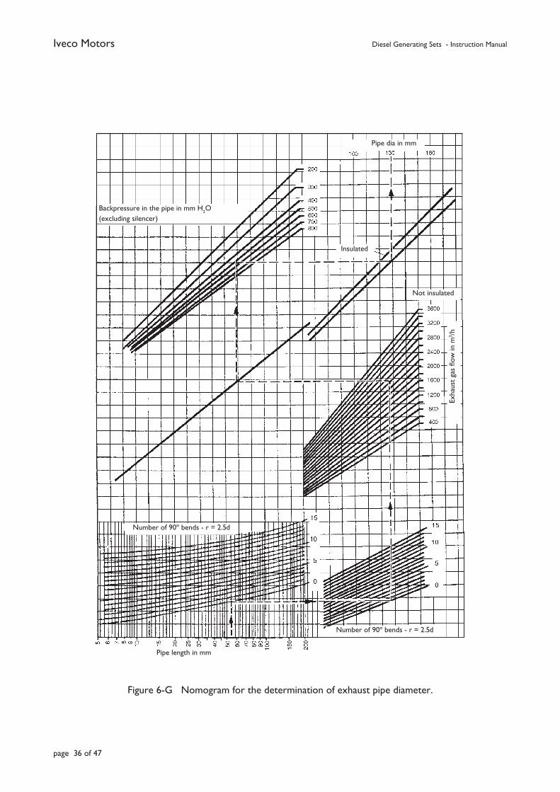
Iveco Motors Diesel Generating Sets - Instruction Manual
page 36 of 47
Figure 6-G Nomogram for the determination of exhaust pipe diameter.
Pipe dia in mm
Backpressure in the pipe in mm H2O
(excluding silencer)
Insulated
Not insulated
Exha
ust
gas
fl ow
in m
3 /h
Pipe length in mm
Number of 90º bends - r = 2.5d
Number of 90º bends - r = 2.5d
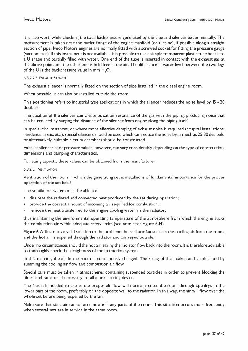
Iveco Motors Diesel Generating Sets - Instruction Manual
page 37 of 47
It is also worthwhile checking the total backpressure generated by the pipe and silencer experimentally. The measurement is taken near the outlet fl ange of the engine manifold (or turbine), if possible along a straight section of pipe. Iveco Motors engines are normally fi tted with a screwed socket for fi tting the pressure gauge (vacuometer). If this instrument is not available, it is possible to use a simple transparent plastic tube bent into a U shape and partially fi lled with water. One end of the tube is inserted in contact with the exhaust gas at the above point, and the other end is held free in the air. The difference in water level between the two legs of the U is the backpressure value in mm H
2O.
6.3.2.2.3. EXHALIST SILENCER
The exhaust silencer is normally fi tted on the section of pipe installed in the diesel engine room.
When possible, it can also be installed outside the room.
This positioning refers to industrial type applications in which the silencer reduces the noise level by 15 - 20 decibels.
The position of the silencer can create pulsation resonance of the gas with the piping, producing noise that can be reduced by varying the distance of the silencer from engine along the piping itself.
In special circumstances, or where more effective damping of exhaust noise is required (hospital installations, residential areas, etc.), special silencers should be used which can reduce the noise by as much as 25-30 decibels, or alternatively, suitable plenum chambers should be constructed.
Exhaust silencer back pressure values, however, can vary considerably depending on the type of construction, dimensions and damping characteristics.
For sizing aspects, these values can be obtained from the manufacturer.
6.3.2.3. VENTILATION
Ventilation of the room in which the generating set is installed is of fundamental importance for the proper operation of the set itself.
The ventilation system must be able to:
• dissipate the radiated and convected heat produced by the set during operation;• provide the correct amount of incoming air required for combustion;• remove the heat transferred to the engine cooling water via the radiator;
thus maintaining the environmental operating temperature of the atmosphere from which the engine sucks the combustion air within adequate safety limits (see note after Figure 6-H).
Figure 6-A illustrates a valid solution to the problem: the radiator fan sucks in the cooling air from the room, and the hot air is expelled through the radiator and conveyed outside.
Under no circumstances should the hot air leaving the radiator fl ow back into the room. It is therefore advisable to thoroughly check the airtightness of the extraction system.
In this manner, the air in the room is continuously changed. The sizing of the intake can be calculated by summing the cooling air fl ow and combustion air fl ow.
Special care must be taken in atmospheres containing suspended particles in order to prevent blocking the fi lters and radiator. If necessary install a pre-fi ltering device.
The fresh air needed to create the proper air fl ow will normally enter the room through openings in the lower part of the room, preferably on the opposite wall to the radiator. In this way, the air will fl ow over the whole set before being expelled by the fan.
Make sure that stale air cannot accumulate in any parts of the room. This situation occurs more frequently when several sets are in service in the same room.
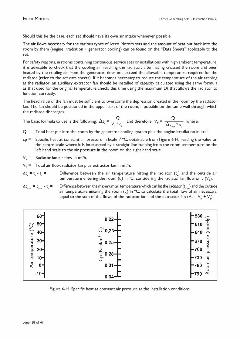
Iveco Motors Diesel Generating Sets - Instruction Manual
page 38 of 47
Should this be the case, each set should have its own air intake whenever possible.
The air fl ows necessary for the various types of Iveco Motors sets and the amount of heat put back into the room by them (engine irradiation + generator cooling) can be found on the “Data Sheets” applicable to the set.
For safety reasons, in rooms containing continuous service sets or installations with high ambient temperature, it is advisable to check that the cooling air reaching the radiator, after having crossed the room and been heated by the cooling air from the generator, does not exceed the allowable temperature required for the radiator (refer to the set data sheets). If it becomes necessary to reduce the temperature of the air arriving at the radiator, an auxiliary extractor fan should be installed of capacity calculated using the same formula as that used for the original temperature check, this time using the maximum Dt that allows the radiator to function correctly.
The head value of the fan must be suffi cient to overcome the depression created in the room by the radiator fan. The fan should be positioned in the upper part of the room, if possible on the same wall through which the radiator discharges.
The basic formula to use is the following: and therefore where:
Q = Total heat put into the room by the generator cooling system plus the engine irradiation in kcal.
cp = Specifi c heat at constant air pressure in kcal/m3 ºC, obtainable from Figure 6-H, reading the value on the centre scale where it is intersected by a straight line running from the room temperature on the left hand scale to the air pressure in the room on the right hand scale.
VR = Radiator fan air fl ow in m3/h.
VT = Total air fl ow: radiator fan plus extractor fan in m3/h.
∆tv = t
v - t
a = Difference between the air temperature hitting the radiator (t
v) and the outside air
temperature entering the room (ta) in ºC, considering the radiator fan fl ow only (V
R).
∆tmax
= tmax
- ta = Difference between the maximum air temperature which can hit the radiator (t
max) and the outside
air temperature entering the room (ta) in ºC, to calculate the total fl ow of air necessary,
equal to the sum of the fl ows of the radiator fan and the extractor fan (VT = V
R + V
E).
Figure 6-H Specifi c heat at constant air pressure at the installation conditions.
VT =
Q
∆tmax
* cp
∆tv =
Q V
R * c
p
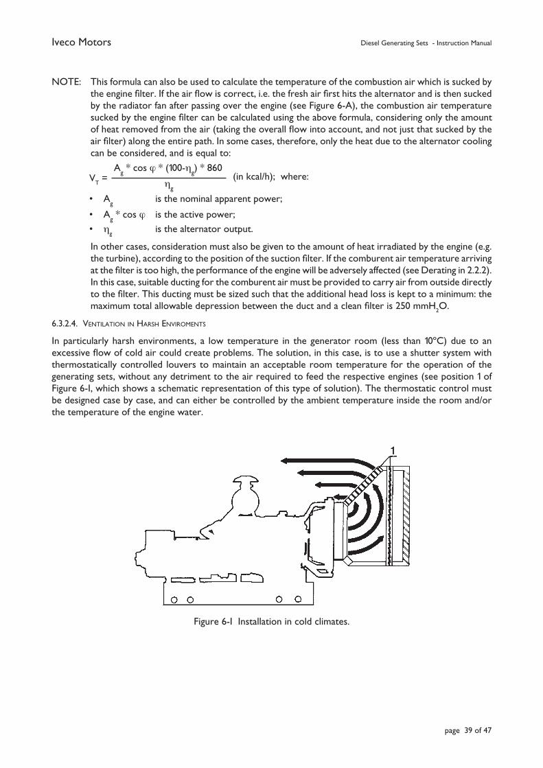
Iveco Motors Diesel Generating Sets - Instruction Manual
page 39 of 47
NOTE: This formula can also be used to calculate the temperature of the combustion air which is sucked by the engine fi lter. If the air fl ow is correct, i.e. the fresh air fi rst hits the alternator and is then sucked by the radiator fan after passing over the engine (see Figure 6-A), the combustion air temperature sucked by the engine fi lter can be calculated using the above formula, considering only the amount of heat removed from the air (taking the overall fl ow into account, and not just that sucked by the air fi lter) along the entire path. In some cases, therefore, only the heat due to the alternator cooling can be considered, and is equal to:
(in kcal/h); where:
• Ag is the nominal apparent power;
• Ag * cos ϕ is the active power;
• ηg
is the alternator output.
In other cases, consideration must also be given to the amount of heat irradiated by the engine (e.g. the turbine), according to the position of the suction fi lter. If the comburent air temperature arriving at the fi lter is too high, the performance of the engine will be adversely affected (see Derating in 2.2.2). In this case, suitable ducting for the comburent air must be provided to carry air from outside directly to the fi lter. This ducting must be sized such that the additional head loss is kept to a minimum: the maximum total allowable depression between the duct and a clean fi lter is 250 mmH
2O.
6.3.2.4. VENTILATION IN HARSH ENVIROMENTS
In particularly harsh environments, a low temperature in the generator room (less than 10ºC) due to an excessive fl ow of cold air could create problems. The solution, in this case, is to use a shutter system with thermostatically controlled louvers to maintain an acceptable room temperature for the operation of the generating sets, without any detriment to the air required to feed the respective engines (see position 1 of Figure 6-I, which shows a schematic representation of this type of solution). The thermostatic control must be designed case by case, and can either be controlled by the ambient temperature inside the room and/or the temperature of the engine water.
Figure 6-I Installation in cold climates.
VT =
Ag * cos ϕ * (100-η
g) * 860
ηg
Iveco Motors Diesel Generating Sets - Instruction Manual
page 40 of 47
6.3.2.5. FUEL SYSTEM
The standard Generating Sets normally supplied by Iveco Motors are fi tted with a complete fuel system from the engine to the standard fuel tank incorporated in the base of the unit.
In order to satisfy particular requirements or standards, a special separately mounted tank of the required capacity can be provided. In this case, the new tank is connected to the engine by fl exible couplings and pipework anchored by suitable brackets. The capacity of the service tank must be proportional to the rated power of the diesel engine and must take into account the limitations provided for by safety laws in the country of installation.
The fuel lines include:
- fuel delivery to the engine injection pump;
- fuel overfl ow from the injection pump;
- fuel injector overfl ow return.
The above fuel lines must be in seamless steel, iron or copper. Galvanised steel pipe must not be used.
The diameter of the pipes can be obtained from information supplied in the engine installation diagrams which are generally valid for pipe lengths of less than 5 metres. For longer lengths, the pipes must be sized case by case.
The fl exible couplings, necessary for isolating the fi xed parts of the new tank and fuel system from the effects of vibrations induced by the engine, may be of the following types depending on the type of engine:
• short lengths of rubber hose, reinforced with inert fabric and diesel oil and fl ame resistant, according to the standards in force in the country of installation, for connecting to ribbed hose connectors using screw tightened hose clips;
• low pressure hoses, diesel oil and fl ame resistant according to the standards in force in the country of installation, protected by metal sheathing with the ends fi tted with special threaded sealed couplings.
Synthetic resin hoses must be avoided at all costs.
When installing the ancillary components of the plant, maximum attention must be paid to the following aspects:
• well-spaced pipe support brackets to prevent vibration resonance and bending due to self-weight, especially in the case of copper pipe;
• installing the least number of joints possible and with suffi cient airtight properties to prevent the infi ltration of air, to which components under vacuum are frequently exposed (fuel delivery line), an aspect which is frequently neglected in many problematic start-ups;
• fuel lines to and from the tank must terminate below the level of fuel at a distance of 20 - 30 mm from the bottom to prevent air entering and shutting-down the circuit.
These extensions must also be suffi ciently spaced apart (~ 30 cm) to prevent the return fl ow of fuel disturbing the delivery by raising impurities from the bottom of the tank or drawing a fuel-air mixture.
• ensure that the pipes used have been thoroughly cleaned;
• ensure that there are no sudden variations in the pipe sections and use large radii of curvature when forming bends in the pipes.
Iveco Motors Diesel Generating Sets - Instruction Manual
page 41 of 47
The construction and installation of the storage tanks must comply with the standards in force in the country of installation governing the prevention of fi re and pollution.
The position of the storage tanks depends on the topography of each individual installation and must satisfy the following requirements:
• minimum difference in level between tank and suction pump;
• minimum length of piping;
• located far from heat sources;
• easy access to the fi ller nozzle.
The pumping system must consist of one electropump, plus one standby manual pump for emergency situations. The electropump must be automatically controlled by level switches inserted in the service tanks being fed.
The sizing of the pumping system will be in accordance with the hourly fl ows to provide, the topographic characteristics of the installation and the head losses in the pipes.
Pipes and fi ttings will be sized in line with the fl ows required and the distances covered. Pipes may be in copper or drawn black tube. Galvanised steel pipe must not be used.
It is advisable to fi t a rapid action shut-off valve which can be operated from outside the room in an emergency.
The return pipes from the engine to the service tank and from the service tank to the storage tank must not be provided with valves or shut-off systems of any kind.
The breather valves on the tanks must discharge outdoors and at least 2.5 m from ground or walkway level and away from doors, windows and air intakes. The end of the pipe must be protected by a fl ame-trap.
6.3.2.6. ELECTRICAL CONNECTION
The generating sets are supplied already set-up for connection to the user.
The function of the generating set is to substitute the mains electricity supply, and as such, must be considered as an external source of energy. For this reason, the safety devices on the users are not included with the generating set and must be provided by those installing the plant.
All electrical connections must made in accordance with the connection diagrams supplied with the set.
6.3.2.6.1. MANUAL START-UP SETS
The electricity supply cables will be connected to the existing line terminals inside the control board and can be accessed through the lower part of the control board.
6.3.2.6.2. AUTOMATIC START-UP SETS
Cables from the sets, the external mains system and the users must be connected to the respective terminal boards in the control panel.
The set’s power cables must be connected directly to the set itself at the generator terminal board.
Connections for the auxiliary services between the set and the control panel must be effected using a multicore cable and the multiple connector supplied with the set.
The wiring diagram for the connector is supplied with the set.
Iveco Motors Diesel Generating Sets - Instruction Manual
page 42 of 47
6.3.2.6.3. BATTERIES
The starter batteries, which are shipped disconnected, must be reconnected according to the wiring diagram supplied with the set, i.e. with the starter motor cable connected to the positive terminal of the battery and the earth cable to the negative terminal.
6.3.2.6.4. CABLE SIZES
The choice and size of cables to use is the responsibility of the plant installer.
It should be emphasised that using smaller sections than that recommended will cause excessive voltage drops and lead to dangerous overheating of the wiring.
6.3.2.6.5. CABLE LAYNG
All set-user connecting cables on manual sets and set-control panel-mains connecting cables on automatic start-up sets must be laid in suitable channels or ducts.
6.3.2.7. EARTHING
Metal parts of the plant with which people can come into physical contact and which, due to an insulation fault or other reasons, may become live, must be connected to an earthing system.
The generating sets mounted on bases and control panels are equipped with an earth terminal.
The sizing of the earth wires to the earthing system and the relative contact resistance must comply with current laws and standards.
N.B.: The earthing system must be located as far as possible from railway/tram lines in order to prevent electro-corrosion of the internal components of the engine in contact with water.
6.3.2.8. HEATING
The rooms in which automatic start-up generating sets are installed must be suitably heated during the cold season. The heating system must ensure that the ambient temperature does not fall to below 10ºC.
These sets must also be provided with thermostatically controlled electric heaters which maintain the water temperature in the engine base at acceptable values, to enable rapid start-up and load take-up without adversely affecting the engine.
7. START-UP
Before starting up the set, take note and comply with the standards and warnings con-tained in the “use and maintenance” documentation for the engine and generator making-up that particular set (see 1.3). We strongly recommend that you read the leafl et “START-UP OF THE ELECTRIC GENERATOR SETS” carefully.
The fi rst start-up, or commissioning, must be performed by specialist personnel.
8. ESERCIZIO
8.1. PROCEDURES FOR THE OPERATION OF MANUAL AND AUTOMATIC UNITS
Referring to the specifi c documentation supplied with each manual or automatic control board.
Iveco Motors Diesel Generating Sets - Instruction Manual
page 43 of 47
9. MAINTENANCE
In order to ensure that the generating set provides good service and maintains good performance levels, it is essential that the maintenance operations specifi ed by the manufacturer are carried out.
It is also good practice to prepare service cards which programme the various operations to be carried out, including day-by-day reporting of hours run, adjustments made, any topping-up of oil, water or fuel, maintenance work or repairs carried out.
Maintenance must be carried out by specialised personnel using the proper equipment.
All maintenance operations must be carried out while the set is shut-down and with the function selector in the “OFF” position.For automatic sets, the battery checks and non-automatic refuelling, water and oiltopping-up operations can only be carried out with the selector in “Manual” (never inAutomatic or in “Test” mode). The set must nevertheless always be shut-down. Maintenance operations on the Electric Control panel must be carried out taking all the necessary precautions against the risk of contact with live components and, in particular, with the set shut-down, the function selector in the “OFF” position and the panel isolated from the mains.
9.1. MANUALLY CONTROLLED SETS
I. ENGINE - perform the necessary periodic maintenance operations as specifi ed for that particular engine, in particular, replace the fi lter cartridges (fuel and oil) and clean the air fi lter.
II. GENERATOR - perform the necessary operations in line with the requirements for that particular generator.
III. Periodically check the fuel, water and oil levels according to the number of hours run.
IV. BATTERY - check the liquid and charge level. If necessary top-up the acid solution with distilled water.
V. CONTROL PANEL - check the condition of the fuses weekly.
VI. Check the connections, contact wear and thoroughly clean once a month.
Special care must be taken in environments with suspended particles in the air in order to prevent clogging the fi ltration and cooling systems.
NOTE: When a set is installed outdoors, in dusty or desert locations, or in the presence of suspended particles in the air, special care must be taken in cleaning of the sets. Any dust or particles preventing the irradiation of generated heat can cause overheating.
Special attention must be paid to:• the air fi lter and pre-fi lter, which must be kept very clean;• the radiator, to prevent air passages from becoming blocked and thus reducing its cooling capacity;• the generator, which must be periodically cleaned internally with dry compressed air to prevent clogging
and insulation losses. NEVER use compressed air to clean the electronic voltage regulator, use a vacuum cleaner;
• the control panel, which must be cleaned using a vacuum cleaner only. Do not use compressed air in the control panel.
When carrying out these operations, it may be necessary to remove parts of the casing. This should only be done after having checked that the set cannot start-up accidentally. At the end of the operation, fi rst replace the casing and then prepare the set for start-up.
Iveco Motors Diesel Generating Sets - Instruction Manual
page 44 of 47
9.2. AUTOMATIC SETS
In addition to carrying out the same operations specifi ed for the manual sets, in view of the particular nature of the type of service, i.e. start-up at any moment even after long periods of inactivity, automatic generating sets also require the following additional periodic maintenance operations to be carried out:
I. BATTERY: check the liquid and charge level once a week. The rectifier used to maintain the battery charge must always be set on “automatic”. If necessary, place the battery on “full charge” for the required period. Check the specifi c gravity of the electrolyte every 45 days.
II. LIQUID LEVELS: check the fuel, oil and water levels weekly.
III. LUBRICANT: even if the number of service hours required for an engine oil change has not been reached, it is good practice to perform an oil change at least once a year.
IV. SET CHECK: perform a running check at idling speed once a week and, if possible, with a load once a month.
V. ELECTRICAL CONNECTIONS: check the connections between the engine’s electrical components and the control panel once a month, making sure they are tight.
VI. CONTROL PANEL: check the entire unit once a year, checking the tightness of all terminals. Carry out a general cleaning using a vacuum cleaner. Check the wear and cleanliness of the relays and remote switches.
VII. WATER HEATER: during winter, check that the engine pre-heater is working correctly once every 2 days.
MISCELLANEOUS:• Regularly inspect the condition of the suction circuit fi lter. The maintenance intervals vary depending
on the season and operating conditions. In particularly dusty environments, a more frequent maintenance is necessary.
• Periodically check the electrolyte level in the batteries and, if necessary, top-up with distilled water only.
• Keep the battery clean.• Always try to keep fuel tanks as full as possible to prevent condensation.• Periodically drain the water and sediment from the tank.• Periodically replace the fuel fi lter when a pressure drop is noticed or when there is a deterioration
in the performance of the Generating Set.• Periodically check the voltage and condition of the alternator drive belts.
9.2.1. INSTRUCTIONS FOR IDLING TEST
• place the function selector in “Test” mode;• check that the start-up operations are correct, except for switching the set to the mains;• check the rating data (voltage, frequency, etc.);• check operation at nominal speed for 10 - 15 minutes;• replace the function selector in “Automatic”;• check that the shutdown operation are correct and that the set is ready for a new start-up.
NOTE: If, during idling tests, the mains power fails, the generating set in operation will take-up the load in a fraction of a second, switching-off the mains remote controlled switch and switching on the set remote controlled switch.
Iveco Motors Diesel Generating Sets - Instruction Manual
page 45 of 47
9.3. STARTER BATTERIES AND AUXILIARY SERVICES
9.3.1. GENERAL REQUIREMENTS
The lead batteries used by the Iveco Motors sets are the reduced maintenance type. Consequently, they only require a periodical check of the electrolyte level and the occasional topping-up with distilled water. In general, the acid level should be between the level lines marked on the body of the battery measured 2 hours after charging.
In the case of manual sets, remove the key from the starter switch during periods of set shutdown.
Do not provoke short-circuits by placing spanners or other tools on the battery or cable connections.
9.3.2. CLEANING
The terminals and connections must be kept dry and clean. To prevent oxidation, clean and coat the terminals with Vaseline.
Check and clean-up any acid spills as this will result in the corrosion of the steel chassis
9.4. TROUBLESHOOTING
The following table constitutes a guide to resolving some of the problems which may occur during the running of a generating set.
In all cases, we strongly recommend that the troubleshooting guides contained in the manuals supplied by the manufacturers of the engine, alternator and other components are followed.
Any operations carried out to resolve problems must be effected by qualifi ed personnel or by an authorised workshop.
Before carrying out any checks or repairs, carefully read chapter 3 “Safety Requirements” and the documents referred to therein.
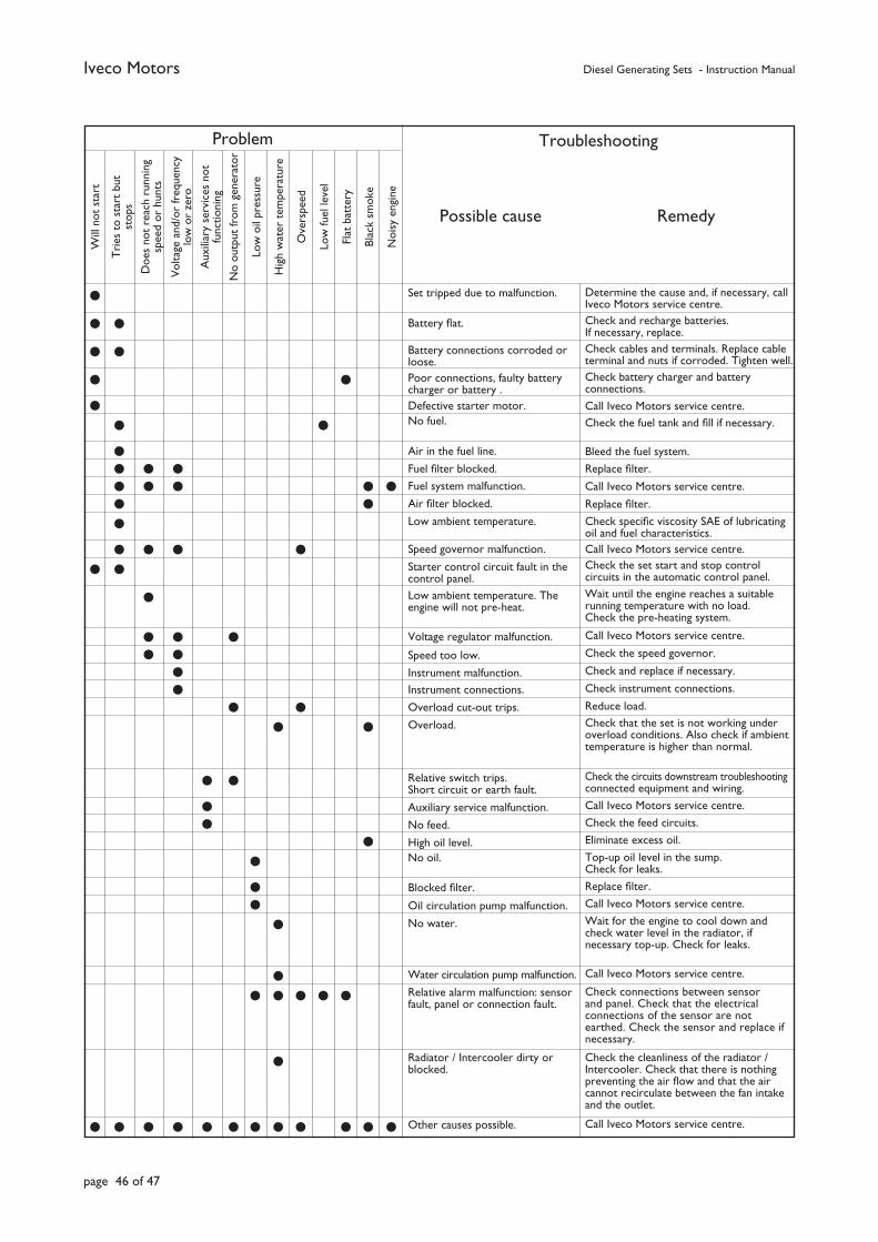
Iveco Motors Diesel Generating Sets - Instruction Manual
page 46 of 47
Will
not
sta
rt
Tri
es t
o st
art
but
stop
s
Doe
s no
t re
ach
runn
ing
spee
d or
hun
ts
Vol
tage
and
/or
freq
uenc
y lo
w o
r ze
ro
Aux
iliar
y se
rvic
es n
ot
func
tioni
ng
No
outp
ut fr
om g
ener
ator
Low
oil
pres
sure
Hig
h w
ater
tem
pera
ture
Ove
rspe
ed
Low
fuel
leve
l
Flat
bat
tery
Blac
k sm
oke
Noi
sy e
ngin
e
Problem Troubleshooting
Possible cause Remedy
Set tripped due to malfunction. Battery fl at.
Battery connections corroded or loose.Poor connections, faulty battery charger or battery .Defective starter motor.No fuel.
Air in the fuel line.
Fuel fi lter blocked.
Fuel system malfunction.
Air fi lter blocked.
Low ambient temperature.
Speed governor malfunction.
Starter control circuit fault in the control panel.Low ambient temperature. The engine will not pre-heat.
Voltage regulator malfunction.
Speed too low.
Instrument malfunction.Instrument connections.
Overload cut-out trips.
Overload.
Relative switch trips. Short circuit or earth fault.
Auxiliary service malfunction.
No feed.
High oil level. No oil.
Blocked fi lter.
Oil circulation pump malfunction.
No water.
Water circulation pump malfunction.
Relative alarm malfunction: sensor fault, panel or connection fault.
Radiator / Intercooler dirty or blocked.
Other causes possible.
Determine the cause and, if necessary, call Iveco Motors service centre.Check and recharge batteries. If necessary, replace.Check cables and terminals. Replace cable terminal and nuts if corroded. Tighten well.Check battery charger and battery connections.
Call Iveco Motors service centre.Check the fuel tank and fi ll if necessary.
Bleed the fuel system.
Replace fi lter.
Call Iveco Motors service centre.
Replace fi lter.
Check specifi c viscosity SAE of lubricating oil and fuel characteristics.Call Iveco Motors service centre.Check the set start and stop control circuits in the automatic control panel.Wait until the engine reaches a suitable running temperature with no load. Check the pre-heating system.
Call Iveco Motors service centre.
Check the speed governor.
Check and replace if necessary.
Check instrument connections.
Reduce load.Check that the set is not working under overload conditions. Also check if ambient temperature is higher than normal.
Check the circuits downstream troubleshooting connected equipment and wiring.
Call Iveco Motors service centre.
Check the feed circuits.
Eliminate excess oil.
Top-up oil level in the sump. Check for leaks.
Replace fi lter.
Call Iveco Motors service centre.
Wait for the engine to cool down and check water level in the radiator, if necessary top-up. Check for leaks.
Call Iveco Motors service centre.
Check connections between sensor and panel. Check that the electrical connections of the sensor are not earthed. Check the sensor and replace if necessary.
Check the cleanliness of the radiator / Intercooler. Check that there is nothing preventing the air fl ow and that the air cannot recirculate between the fan intake and the outlet.
Call Iveco Motors service centre.
Iveco Motors Diesel Generating Sets - Instruction Manual
page 47 of 47
10. DEMOLITION
The Generating Set and its components contain materials which, if not disposed of in the correct manner, can create serious ecological damage.
The following materials must be delivered to authorised collection centres for disposal:
• starter batteries;
• used lubricating oil;
• water and antifreeze mixtures;
• fi lters;
• auxiliary cleaning materials (e.g. greasy rags or rags soaked in fuel and/or chemical cleaning products).
A generating set which is no longer serviceable must be delivered to an organisation approved for the demolition of industrial machinery.
All component materials must be collected, sorted, recycled and/or disposed of in line with that provided for by laws in force in the country of installation. In particular, all requirements appertaining to directives 91/156/CEE and 91/689/CEE relating to refuse and hazardous waste respectively.
Waste products must not be disposed of in an unauthorised manner.
All waste products are potential sources of danger and environmental pollution.