dieterkonig darmstadt, germany - nasa · table 1. companion of test methods f_nunues_ test mz_od...
TRANSCRIPT
A NEW TEST METHOD FOR THE ASSESSMENT OF THE ARC TRACKING PROPERTIES OF
WIRE INSULATION IN AIR, OXYGEN ENRICHED ATMOSPHERES AND VACUUM
DieterKonig N94- 28714Technical University of Darmstadt
Darmstadt, Germany
Published Information on the Activities of the
Cooperating Group THD / ERNO / ESA-ESTEC
It
1 2
[3
F Dricot, H.J. Reher
D K6nig, F.RFrontzek
F. Dricot, HJ. Reher
MD. Judd
ESA/ESTEC
[ 4 ] M.D. Judd
[5] ESA/ESTEC
[8 ] D. KOaig, F.RFrontzek
H.J. Re.her, M.D Judd
Survey of Arc Tracking on Aerospace Cables and
Wires.
Post-Deadline Proceedings of the XVth Intern.
Syrup. on Disch_ge$ and Electrical Insulation in
Vacuum, September 6 - 10, 1992. Darmstadt,
Germany, pp. 24 - 30, to be published in
IEEE Trans. on Electrical Insulation
Principle of a New Arc Traehng Test of Cables and
Wires for Spacecraft.
Conferenceon Electricalinsulationa.adDielectric
Ph_omena (CEIDP), October 18 - 21, 1992,
Victoria, BC, Camazia, pp. 363 -369
Survey of Arc-Tracking. Final report, October 1991,
submitted by MBB/ERNO. Internalpaper.
Authors: F. Drieot, tt.J. Reher
Presentauon of Activities in the Field of Arc
Tracking of Wire Insulations (ESA/EKNO)
MaterialsAnd Processes Technical Interchange
Meeting,Reston, VA, September i - 3, 1992
Arc Tracking Tell of Wires. Report of Phase 1.
J_uary 1993, subuntted by ERNO. Internal paper.
Authors: F. Dricot, H.J. Rehea
A New Test Method for the Assasment of the Arc
Tracking Propenim of Wire Insul,tion in Air,
Oxygen Enriched Atmolpheres and Vacuum.
6th Int. Syrup. on the Flammability and Sensitivity
of Materials in Oxygen Enriched Atmospheres,
Noordw_jk, May 11 - 13, 1993 (oral presentation)
173
https://ntrs.nasa.gov/search.jsp?R=19940024211 2018-08-12T23:01:59+00:00Z

Contents
1. Introduction
2. Reasons for the Development of a New ar_ Tracking Test
of Wires for Space Application
3. New Test Concept
4. Test Equipment
5. Test Results
6. Conclusion
A Phenomenon on the surfaceofthe
insulationmaterials
(Def. of G.A. Day)
ARC
A kind of electr, discharge mamiy
between two or more
(Def. of Compton)
Interactionof differentphenomena
causingarcingand faultpropagation
inwire bundles
A. G. DAY
Tracking
Ta,_x_G h an untidy process; its incidence depends upon the insulation
but its incepuon depends upon several other factors. By definition, tracking
is the formation of a permanent conducting path across a surface of the
insulation, and in most cases the conduction results from degradation of the
immlation imelL I_ is therefore necessary for organic insulation to be
present if tracking is to occur.
The three essentials of the tracking phenomenon are:
(t) the presence oi a conducting film across the surlace of the insulation,
(=) a mechanism whereby the leakage current through the conducting
film is interrupted with the production of sparks,
(3) degradation of the insu/ation must be caused by the sparks.
174

Definition of an Arc
Probably the best definition of an arc is that due to Compton:
namely,
the arc is a discharge in a gas or vapor with a voltage drop in
the cathode region that is of the onier of the lowest ionization
potential of the gas or vapor in which it burns,
The voltage of short arcs is usually in the range 10 - 50 V. This
arc drop is divided between ano_ and cathode drops (usually
of the order of 10 V; often the anode drop is considerably
higher than the cathode drop) and the balance in the column
that depends on its length. Arc currents are usually from the
order of one to many thousands amner¢,,l.
ARC TRACKING TESTS
Development of wet arc
test methods
Initiated by incidents of arcing
recorded under wet conditions:
e.g- a failure of a cable bundle
on a Monarch Airlines aJrcraft
caused bya leak.rag tOtJeL
Development of £[£Y-.a_
trac_ne test methods
Other incidentsof arc igmtions
Tecorded in dry.conditions
(rnechamcai damage of insuia-
tio_ electrical sparksetc.)
Comparison of existing test methods
_: No appropriate arc tracking test
for space application avazlablc
Development of a new test method suitabie
for the Ltsemment of the resistance of arco-
space cables to arc tracking for diHerent spe-
ci_c _ and network conditions of
175

Tshlc 1. Co=p&moa of Test Met_ds (pubhshed at CEIDP, 1992)
Test metaod comp_soa
1.1. Pow_ so_ce
&) Ac.2n0/llSV,4001_
b) ec
c) othm
1.2. Cazzent
a) ame valme _r allcable msm aad Wpes
b) depea:lot f=0= ,he am_a_cantor of the tmteei cabAe
mt from _e p_v.mvei c) dewce cg m, tem_t cal_
1.3. RaLsAisa to recovery voRage
2. An: _ W=mm
a) we_ t_uoa method
b) ctrrJ_suoa me,_zoct
]. _c _=a_ am amnat _
a) pin'.act,re =xcu:; brea3a_
_b) seff--zmzac_m of :he axe
Test met ao_Ls:
Inl _gJ fej fTV (_1 Ixal I1¢! (u
-- -- - vLr VS_ --
- - 1) 2) - - :) i)
* .... * 11 S)
-- -- ., ÷ ÷ -- _ -
-- -- 4. + -- - -
+ + - _ _ . -
- + ¢. + + _. -- v
1) DC, _ V, 2) DC+AC3) A¢, 100V...e00Y4) De, 220V5) limited b7 R = 20 gl6) --" 10"7) wee,, L, cLry,, S
L+)_ m yes; ,,_' = nO |t&r, emelB?.
var • variable
[8]
iT]
18]
[9]
[lo]
Aerospatiale Test 480.202/87A: Electrical Cables. Aerospatlale
Test Methods for Investigations of the Arc Tracking Design.
ASTM D 09.10 (October 89): Dry Arc Resistance _md FAult
Propagation.
BSG 230 Test 42: Resistance to Wet Arc--Track/rig.
BSG 230 Test 43(Draft): Dry Arc Test.
IEC II2/VDE 0303, Teil h Method for Determining the
Compazative and the Proof Tracking Indices of SoLid Insulating
Materia_ under Moist Conditions (VDE Specification).
DIN VDE 0303, Tell 5: Testing of Electrical Insulating Materials
-- Low--Voltage High--Current Arc Resisting Test (in German).
NASA TP WSTF--655: Arc Resistaace in Space Grade WIre.
NHB 8060.1C Test 18: Arc--Tracking.
176

Table 1. Companion of Test Methods f_nunues_
Test mz_od comparison
a:m
s) A.iz and= as.mmpnenc p:essture
b) Art mtb _nchc, d Q2
,c) Vacamn
d) Mecktm_ _bnmoa
Test _:
f n I I O t f e I [ 7 ] [21 [131 lzol In]
...... 4. 4.
4. ÷ 4. 4. _. -- --
d) poauon- ve_acLt- Ismmas_-othn
d. Test d_'--"
7. EvaJsumon ¢_'lserda
s) Bzem_ ume of the ate
b) _ d the arc ps_
c) lzsu_oa mmuace _t
d) Zlecmc nnu_b t_t
e) ContzanztT test of c0zzdv£ton
r) Vir_ e_w,z_
i) " i) - " "L S 7) S S S S 9
4. 4. -- -- ._ • -- 4.
4. 4, ..... 'b
• • * • 4. 4. -- --
[6]
[T]
[81
[9]
[,0]
Aerospztiaie T_t 480.202/87A: Electrical Cables. AeroapatLs, le
Test Methods for lnves_gar, ions oz" the Arc Tzack/zzg Design.
ASTM D 09.10 (October 89): Dry Azc Resistance and Fault
Propagation.
BSG 230 Test 42: Resist•ace to Wet Arc--Tracking.
BSG 230 Test 43(Draz.t): Dry Arc Test.
[EC II2/VDE; 0303, Tell i: Method for Decerm/ning the
Cornpazstive a_ the Proof" Tracking Indices of SoLid [nnul_ting
MaterizJs un,_er Moist Conditions (VDE SpecificzCion).
DiN VDE 0303. Tell 5: Testing oz. Electric-,[ Insulating Materials
-- Low--Voltage High--Current Arc P,csisting Test (in Germgn).
NASA TP WSTF---655: Arc Reeiat_nce in Space Gz,t_:ie Wires.
NHB 8060.lC Test 18: Arc--Tr_ckin_.
177

PR/NCIPLES OF A NEW ARC-TRACKING TEST
The followingprmcipleshave been mcorpotated intothe new testmethod.
s. Test equipment enables wires to be tested in vacuum, normal air (atmosphenc pressure) and m an ennched oxygen
annosphere (at almosphe_ric and reduced pressure).
b. The supply voltage is adjustable. Durmg test the current is rail/ally set on the nominal current rahng (mcludmg deraringit"applied) of the cable. Subsequent tests should be performed at different current values to assess the capability of the
wire to withstand stress.
c. The arc is ignited by melting of an ignition wire (filament) ensuring that the mfiuence of the ignxuon on the arcbehaviour is minunised.
d. Switching cycles are applied to the test voltage (presently I0 sec. on, 3 min. offend a further lO sec, on)
e. Damage is educed m the cable in a clearly defined location.
f. Evalualion criteria should be based on the test results and on any post test measurements such as:
Remammg "conduction funcuon" of the conductorsPost test insulation state of damaged and/or undamaged cable bundles
Arc duxazJonand path lengthMcas_cment of elc_mcaJ clu_ractcnstics during lest
Visual records and post test inspection
closed
, Video recording
Switching Cycle, Measurementsand Evaluation Criteria
closed
opsn
3 mln. _ I10 se_!
_t measurement
_ Continuity check
of conductors
Recording of arc current
(transient recorder)
Recording of arc voltage
trsrmient recorder)
- Insulation resistance
- Length of arc traces
- Post test Irmpection
Accept/Reject Criteria: still under consideration
Bask= Ideas: Simple ¢rttmqa based on selected
post test memmrsment,*; support by
eleMrimll end op#cal records taken
during test.
178

Module I
'i- 220V
Scheme of the Arc Tracking Test Arrangement
i I= Module II JI i
?.'I 7.2 7._]__i___
7._ 75
Module III
5
II /
\ r*
5.1)iw' I_.
1,
\ viewing I_ort
7.5_
ExglInI_n of Symbo4s: see (51
I I= Module IVI
E.1
IL, ._- Air N 7 0 7
.F63 6L.
_, 2;-I56 1
65_--_:: .J
Test sample configuration
marking of the cables
20to30 20to30 20to30
t .....' t i
cable bunde
,terminal board
i-T3
m_
!-3.
_-TE_
20 to 30 20 to 30 20 to 30L _
"Damage"! p
View on arrow A
n _=-_ .-,=16_[_rt.2_. - Cables Nr. 3 and 4: damaged
"7 Cables Nr. 1,2,5,6 endT: undamaged
exploding _gniterwire
A
179

Test Procedure (Draft)
A NEW ARC-TRACKING TEST
a. Prepare test samples as described earlier and install in chamber.
h. Establish test atmosphere.
c. Adjust current to nominal ratillg for wiro under test
d. Activate lest recording devices (video, transient recorder etc.)
e. Power to the test sample should bc activated for l0 seconds to imitate the ale aJld allen deactivated, Ariel a peraod of
3 minutes power to the sample initiated for a lurther 10 steroids to lest for arc Iracking potential and damage
f. During test the sample shall be observed and video recorded Arc currenl and arc voltage are recorded by the Iranslel|t
recorder.
g. Al_er lest the following measnremenls are made:
- Electrical reststance of the conductors of the sample,
- Insulation resistance between damaged and / or undamaged wires A valne of at least 0,5 MC2 at 500 V DC is
required.
It. if the test sample fails the test should be repeated on a new sample at a lower test current.
TypicalTestResults:4 differentarcextinctionpatterns
The followingfourtypicalarcextinctionpatternshavebeenobserved:
I.Self_xtinguishingarcwithoutreignitions(SE)
2.Arc extinctioncausedbymetallicshortcircuitingoftheconductors(M)
3.Arc extinctioncausedbytowresistanceshortcircuitingoftheconductors(R)(conductivematerialgeneratedfrommolteninsulatingmaterialand conductorsbridgingtheconductors)
4. Arc extinctioncausedbyclearingofthecontrolcircuitbreaker(CI)(UnderpracticalconditionsastablearcwithadurationexceedingthetestdurationtimeofI0sec.hastobeexpected)
180

?.0 ; h_.T"
a)
_-, .r
_-I '=1
_t _t
';JI
r
,t utlII
ULH
,)11
iJm
9 °
0
u
0
i arc voltage IIAor SL u = sever_ te_s volts i, f
metillzcshortcJrcmtIM)!u =
arc current
I (t)
I0 ; / Oiv.
i
suppty vohLge
self--extm_uzsh,a_ arc (SE)
_ arc voltage _ ._
arc IR_tzon de]av time
I-
T1
U(t)
I (t)
Fig. 4 a/b. Typical records of test current I (t) end voltage U(t) between the conductors during the time T1 of the switching cycde.
c)
d)
c
0
A U
0
c I (
(
A I
0
2.0; , Oiv.T1
, arc volt&ee
' 11: exuncuon _d:er cuzrent lDteD£tlp*.lO_ by thecontactor(CI)
i i
"' I I2.0s , Oiv.
/l
r
_zcm_muon after nttll _enod
I
u(t)
I (t)
T2
U(t)
I (t)
I
Fig. 4 c/d. TypicaJ records of test current I(t) and voltage U(t) between 1he oonductom during the time T1 (c) and the time T2 (d) ofthe switching cycle.
181

Arc Tracking Test of Wires
Experimental Results
Abbreviations
M - MetalUc short circuit
R Low res/stance short circuit
SE - Se_-extin_shing arc
CI - Am extin-ction after the current interruption by thc contactor
NR - No arc reignition
A - Massive arcing
S Short arc/n 8
CF - Consuming fire
SF - Shon duration fire
G - Glow if current flows
S$ - Short spit
NA - No action
Y Yes
' N No
l_ormation
from recording of current and
voltage with a transient recorder
I_ormation
from video recording
Alter test eJect_cai measurements
Tahb A. I
ho.: TI20
T_ _mlUql_ _ V
'Zlms I: iO s
Pore m T_ _o.
moamlsIimalu
I. Arc U.--_ma 1-1
Ln i T 2
_IR ram. AWG 2C
"J_m o_mm: I0 A
1 2 3 4 6 6
0._-_ O,_,:'L L.4 0._ Z.J, 1.6
O 0 0 0 0 0
2. To*-, _JJzm/K 13 I0 1_ 11 16 IS
_t. F..N_S4;,',,_ Winec_sttuuisy chec_
Win, No.: 1 Y Y Y Y y y
4 yS Y Y yS Y Y Y Y y y7 Y Y Y y y y
kmsr tha.n 0.'- MOmmmm_t f(z ,..b.ef_mmtz ume:
3 3 34 4 4
i I 1I 3 2' S 5
4
$. On
A) T--,,,,--,sTSme I SE M SE SE SZ SE
TLm.8 '_ N'I M NB. NK NK N'K
_) Video mcmUa_.Tlme I S S A,SF S,S'F S S
2 NA NA NA NA NA NA
182

Ta_b/e A. 9
S,_mp_ No.: 1112
Trot _/t_e: 125 V
Tim_ 1:10 J
winHts_ A WG 12
Test cm-nmt: 30 A
Sm,_-J_m_{ eyrie
brn.Lt pemod (Po'wm'm_'): 3 =ha. _ 2:10 *
F._'rL-_Utl Co_d,iUam.m
Norm{tl A_m_lphere with Vacuum
tl.mosp_m enn_ed ox-l{{_
Post tat Te_t No. I 2 3 4 5 6mp._tJultments
1. Axe dttrttton T 1 1.2 1.4 2.9 1.6 0.72 l.,i
in s T 2 0 0 0 0 O O
2 Total burn length
in mm 12 24 40 9 21 13
3. End $o end rare
oonunmty check.Wire No.:
4_ rn_lZJAUOn reilltltne.4_
lower thtn 0.5 Mr2meuured (or the
foUamn 8 wtru:
Y Y Y Y Y Y
Y Y _ Y Y Y
y Y Y YVY Y Y Y
Y Y Y Y Y
Y Y Y Y Y Y
Y Y Y Y Y Y
3 3 3 3 3 3
4 4 4 4 4 4
_....;---_....2....-i...._-....7 7 2 2
5 5
S X6
7 7
S Ob_ervtt,ons
A) Trtnsieot recorder:
Time t R R R R R R
Time 3 R R R R R R
BJ Video recora_:
Time 1 A,CF A,CF A,CF,G A,SF,G A,G A,G
Time 2 SF,G CF,G G HA G O
* - test c_rrent 10 A
_'a12_-10:-
mm 9}-50
8F,5- t
7_-,0
_5 3__n
2}- ..5 H
11- H0i H
51 0"-- _! F'.,_
01 _-- _
I1
Vacuump=10"3Pa
//
//
#_
,\
/,d
..J g..d
24,5%02175,5'I.N2p:1000hPa
CabLeNr.2/20
Conductor/PI/PI/PTFE
30"I.021 _.ir70"l.N2 p:1OOOhPap:7OOhPn
Avmlge vaiue_ of arc duration _, length of am traces l,8nd arc
propagation velocity 9, for cable Hr. 2/20 tuted under difhmmtenvlronmentaJ condlUon_.
Number of t_m for each environmental condition N-5.
183

ram/S10
16
10
mini50
L5
r2o25
20
15
8 10
0
$
9=I
8_
-Itto
1 ;,. .,O_ _ ,"
ok_____.. _
CableNr. 3/20
ConductorlPTFE/PI/PI
Y'Rv",41
v',_l
.,,,I Lm_l
v',_l_//11
..
i
Vecuurn 2t,.5'/,021 30°/,02/p=lO'3pa 75.5"/,N2 70"/oN2
p=1OOOhPop=7OOhPo
m
./,4 I%_il
Air
p=lOOOhPo
Average values of arc duration [,, length of Ire trnces i, and arc
propagation velocity _, for cable Nr. 3/20 tested under different
envlmnmentel oondltJons.
Number of tests for each environmental condition N = 5.
PRELIMINARY TEST RESULTSARC TRACKING TF, ST OF WIRES
TABLE 1. TEST SAMPLE 1/12 (c,b_ _ ^wa 12)
Test-Nr. Path length of damagedcable insulation
in mm
Number of cablaswith insulationresistance < 0.5 Mo
1 N 12 2
2 N 24 1
1 E 40 1
2E 9 l
1V 21 5
2V 13 5
N -- Norm_ &tmosphm_, E - Oxlr_ enriched &tmmpbme, V - Vacnlxm
_: The pathlengthofdamaged cable intuitionseems to benotcorrelated withtheresultsofpost-testmeasurementsofthecableinsulationresistance
184
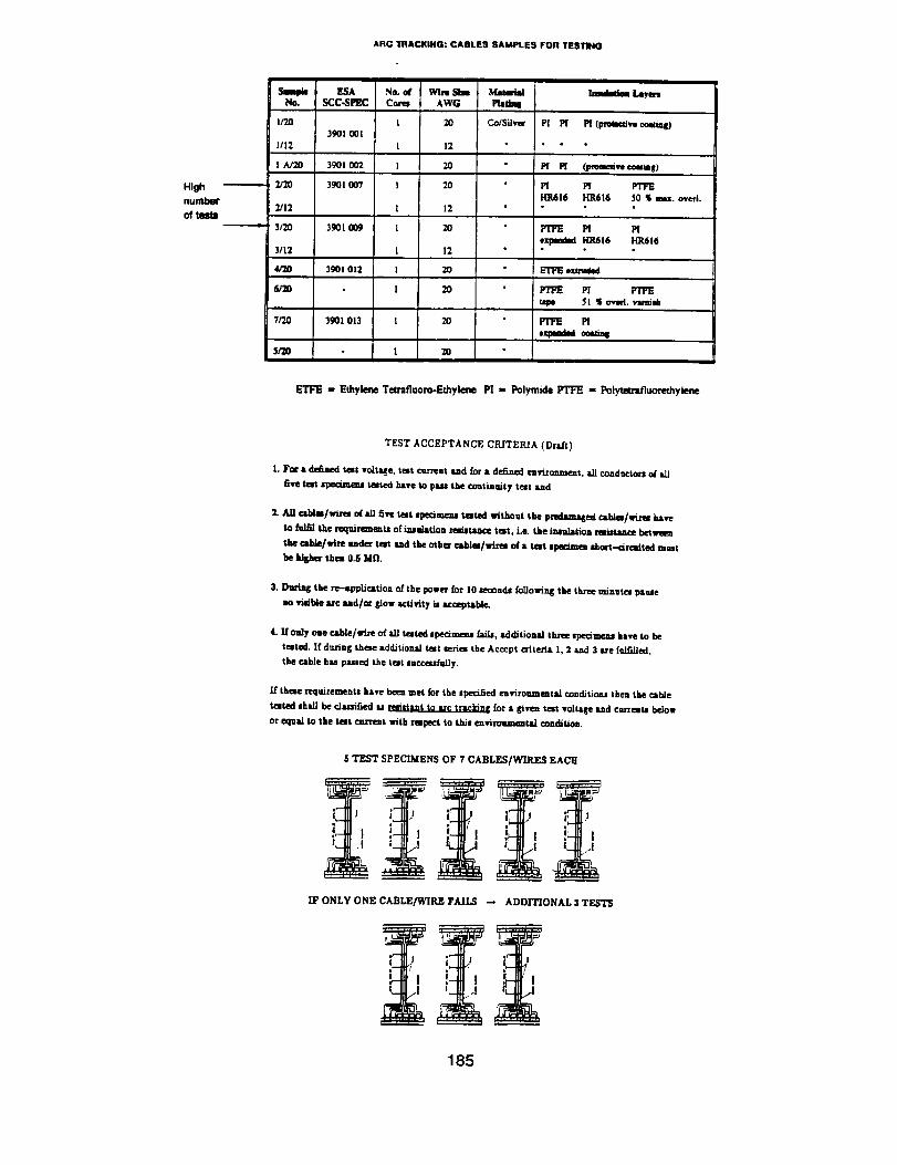
ARC 1"RACKING: CABLES SAMPLES FOR TESTING
HJ_nun_
NSmo" ESA Ne. d Wire SheSCC-SPEC Cot_s AWG
1/20 I 20
39OI 001
1/12 1 12
I A/20 39OI 002 1 20
2/20 3901 007 I 20
2/12 I 12
3/20 3901 009 l 20
3/12 I 12
4/20 39OI 012 ! 20
6/20 I 20
7/7.0 3901 013 1 20
S/a) l 20
Mata.tui
Matt_
Co/Silver
ImtdJlam Layers
PI M I_ (pmtK_,m coetu_)
M M (l_m_ve coma•l)
Pl M PTFE
HIll6 IO1616 50 S ._x. oved.
FrFE M M
expmded HR616 HR616
E'rFE _
P! FrFE
Uqx, 51 _ c_varl. _.ui_
FIFE Pl
eq=mua ee,_s
ETFE - Ethylene Teerafluoro-Echylene Pl - Polymide PTI:E = Polytetrafluorethylene
TEST ACCEPTANCE CR.[TERIA (Drt(t)
1. Foc • defined test voltMe , trot c_'rent lind _or • defined eavizonme_ut, aJJ conductors o/all
five test specunezu tested lutve to p,L,, the COntinUity test tad
2. All cablm/wires o_a/l five test speQmeas tested without the predamagefi mbler/wins have
to fulfil the requirements of iasalation mmtuce test i.e. the insulation smistamce between
the cable/wine •rider test sad the other cab/m/wirer of • test spe_mzca shm't--drcaited must
he kl&hes thon 0.5 Mn.
3. Durialg the re--_pplication of the power for 10 eemncLs foLlowiwg the three minutes pause
no visible Itrc ud/ot &low activity is uccept4tble.
4. If only one cable/wL'e of all testefi ape•meal Lt/I*, additions] three spe_me=s have to be
tested. If during these tdcUtionai test series the Accept criteria 1, 2 aa_cl 3 are fu/filled,
the cable h_, passed the test succusfuLly.
If these tequireme=t8 have bee= met for the specified e=vironmeatai conditiou theu the cabJe
_M sh *11 he classified u " " for a givem test vohzge ud carte=as below
or equal to the test current with rerpoct to this enviro'n.memtLl conditio,,.
5 TEST SPECIMENS OF 7 CABLES[WIRES EACH
; J ; J
!- J
IF ONLY ONE CABLE/WIRE FAILS -- ADDITIONAL 3 TESTS
; _!
185

Table 2 Test Results and Acceptance Statement
Cable specification:Cable size:Rated current: 7,5A
ESA SCC-Spec. 39011007AWG 20 ( 0,52 mm 2)at max. ambient temperature of 85"C
Test voltage: 125 V Environmental conditions (E.C.):1. Normal atmosphere (N)2. Vacuum (V)
TN, t-
10A
7,5A
i E.C.
i
i
i
i
: VIi
[N
SI: V!
tl........
;, Ni
!i
L
i
!i
T
Tn!. Nr, Criterion 1
N_ of ,-_es
t_at fall O_e oonU-
nutty ¢I_aN:K of
conOuctorl
1 1
1 2
1 1
2 1
1 0
2 0
3 0
4 0
5 0
(1.,.7)
Criterion 2
Number" of c.obtes
with In irmulmUon
resistance S 0,SM.Q
0-5)
Criterion 3
Visible arc or
glow i_Nlly
dunng
.P,,pmcauon
of Ins power
(Yes,'No)
Test Result:
The above specified cable is resistent to arc tracking for currentvalues _ 7,5 A at the rated voltage of 125 V and for theenvironmental oondltlons defined as:Normal atmosphere, p • 0,1 MPa
N
N
N
N
N
N
N
N
N
Accep-ted
Yes/No
N
N
N
N
Y
Y
Y
Y
Y
II
• YesI
I rl No
!
• wflhout Ihe pcal-clemmged _ Nr. 3 lind Nr,4
186

Procedure for an estimation of the
arc tracking current limit
I0 12.S%
fall
fell
Restelent to erc uecXmg
for ¢urrentl • 0.75 I n
I
I
1.0.1
1,2,3 .... N = NuntOer _ NIII stY|
test t-,trent mtm
100% It/ I n
187

Conclusion
A briefsummary ofthe resultsobtainedisgiven below. However, itshouldbe
remembered thatthe conclusionsdrawn arebased on limitedseriesof testsand
furtherwork needs tobe done toinvesugatethe effectsof differentparameters.
Inaddition,presentlyaccept/rejectcriteriacan be given only as a draft.Modifi-
cationsmay become necessary,ifrequiredby findings@ore a more extensive
database.
The resultscan thereforebe summarised as follows:
a.
b°
C°
d.
e.
f.
The proposed test method appears to be a useful tool for the assessment of
wire insulation systems under arc tracking stress.
The equipment can be easily adapted for tests at different realistic electricai
network conditions incorporating circuit protection.
The test system works equally well whatever the test atmosphere.
Initial test results confirm published results of the available literature m that
pure Kapton insulated wire has bad arcing characteristics and ETFE insula-
ted wire is considerably better (in air).
Initial test results indicated that for certain wires arc tracking effects are
increased at higher oxygen concentrations and significantly increased under
vacuum. Although this letter point had been suggested flom theoretical
considerations it is believed that this is the first time this has been demon-
strated in practice.
All tests on different cable insulation materials and performed in different
environment mclucling enriched oxygen aunospheres resulted in a more or
less rapid extinguishing of all high temperature effects at the beginning of
the post-test phase. In no case a self-maintained fire was initiated by the
arC.
188