differences between jai proprietary and genicam sfnc ... and jai trigger setup.pdf · trigger...
TRANSCRIPT

1 / 15
JAI Ltd.
Differences between
JAI proprietary and
GenICam SFNC camera settings naming
www.adept.net.au
2 / 15
JAI Ltd.
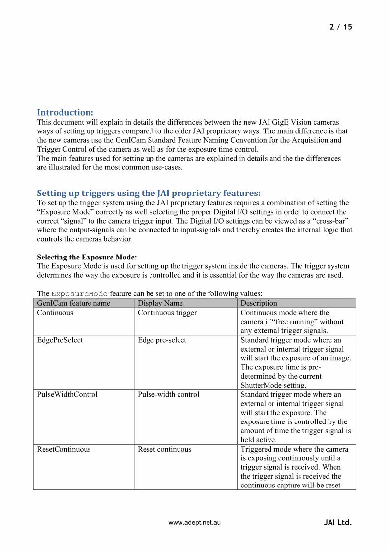
Introduction: This document will explain in details the differences between the new JAI GigE Vision cameras
ways of setting up triggers compared to the older JAI proprietary ways. The main difference is that
the new cameras use the GenICam Standard Feature Naming Convention for the Acquisition and
Trigger Control of the camera as well as for the exposure time control.
The main features used for setting up the cameras are explained in details and the the differences
are illustrated for the most common use-cases.
Setting up triggers using the JAI proprietary features: To set up the trigger system using the JAI proprietary features requires a combination of setting the
“Exposure Mode” correctly as well selecting the proper Digital I/O settings in order to connect the
correct “signal” to the camera trigger input. The Digital I/O settings can be viewed as a “cross-bar”
where the output-signals can be connected to input-signals and thereby creates the internal logic that
controls the cameras behavior.
Selecting the Exposure Mode:
The Exposure Mode is used for setting up the trigger system inside the cameras. The trigger system
determines the way the exposure is controlled and it is essential for the way the cameras are used.
The ExposureMode feature can be set to one of the following values:
GenICam feature name Display Name Description
Continuous Continuous trigger Continuous mode where the
camera if “free running” without
any external trigger signals.
EdgePreSelect Edge pre-select Standard trigger mode where an
external or internal trigger signal
will start the exposure of an image.
The exposure time is pre-
determined by the current
ShutterMode setting.
PulseWidthControl Pulse-width control Standard trigger mode where an
external or internal trigger signal
will start the exposure. The
exposure time is controlled by the
amount of time the trigger signal is
held active.
ResetContinuous Reset continuous Triggered mode where the camera
is exposing continuously until a
trigger signal is received. When
the trigger signal is received the
continuous capture will be reset
www.adept.net.au
3 / 15
JAI Ltd.
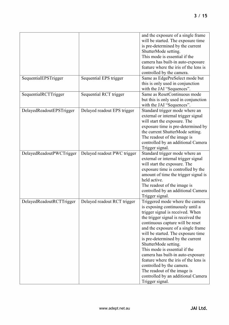
and the exposure of a single frame
will be started. The exposure time
is pre-determined by the current
ShutterMode setting.
This mode is essential if the
camera has built-in auto-exposure
feature where the iris of the lens is
controlled by the camera.
SequentialEPSTrigger Sequential EPS trigger Same as EdgePreSelect mode but
this is only used in conjunction
with the JAI “Sequences”.
SequentialRCTTrigger Sequential RCT trigger Same as ResetContinuous mode
but this is only used in conjunction
with the JAI “Sequences”.
DelayedReadoutEPSTrigger Delayed readout EPS trigger Standard trigger mode where an
external or internal trigger signal
will start the exposure. The
exposure time is pre-determined by
the current ShutterMode setting.
The readout of the image is
controlled by an additional Camera
Trigger signal.
DelayedReadoutPWCTrigger Delayed readout PWC trigger Standard trigger mode where an
external or internal trigger signal
will start the exposure. The
exposure time is controlled by the
amount of time the trigger signal is
held active.
The readout of the image is
controlled by an additional Camera
Trigger signal.
DelayedReadoutRCTTrigger Delayed readout RCT trigger Triggered mode where the camera
is exposing continuously until a
trigger signal is received. When
the trigger signal is received the
continuous capture will be reset
and the exposure of a single frame
will be started. The exposure time
is pre-determined by the current
ShutterMode setting.
This mode is essential if the
camera has built-in auto-exposure
feature where the iris of the lens is
controlled by the camera.
The readout of the image is
controlled by an additional Camera
Trigger signal.
www.adept.net.au

4 / 15
JAI Ltd.
The “ExposureMode” feature can be set from JAI SDK using the following command:
J_Camera_SetValueString(hCamera,“ExposureMode”,<new exposure mode value string>);
Where the <new exposure mode value string> is a string taken from the GenICam feature name
column from the table above.
From the JAI Camera Control Tool the Exposure Mode value can be selected using the drop-down
box like shown in the figure below:
Selecting the Trigger signal:
The primary trigger input for the camera is called “CameraTrigger0”. This is the input signal
that needs to be connected to the appropriate input signal in order for the camera to be triggered by
a signal. The signal can either be an external input (physical input) or an internal signal (such as the
output from a pulse-generator or a Software Trigger signal).
To modify the Digital I/O cross-bar settings the user will have to use the “LineSelector”
feature to select the input signal. The LineSelector is found in the category named Digital I/O.
So in order to connect the camera trigger to for instance the first GPIO input pin the following
features need to be set:
LineSelector=CameraTrigger0 LineSource[LineSelector]=GPIO_PortIn1
This can be done using the JAI SDK using the following lines of code:
J_Camera_SetValueString(hCamera,“LineSelector”,“CameraTrigger0”); J_Camera_SetValueString(hCamera,“LineSource”,“GPIO_PortIn1”);
From the JAI Camera Control Tool the value can be selected using the drop-down box like shown
in the figure below:
www.adept.net.au

5 / 15
JAI Ltd.
The LineSource[LineSelector] feature can be set to one of the following values:
GenICam feature name Display Name Description
Off Off The signal is disconnected
LVAL LVAL The internal LVAL (Line Valid)
signal is connected
DVAL DVAL The internal DVAL (Line Valid)
signal is connected
FVAL FVAL The internal FVAL (Frame Valid)
signal is connected
EEN EEN The internal EEN (Exposure
Enabled) signal is connected
GPIO_PortIn1 GPIO Port In 1 GPIO Port In 1 (Optical in 1) is
connected
GPIO_PortIn1 GPIO Port In 2 GPIO Port In 2 (Optical in 2)
SoftwareTrigger0 Software Trigger 0 The internal Software Trigger 0
signal is connected.
SoftwareTrigger1 Software Trigger 1 The internal Software Trigger 1
signal is connected.
SoftwareTrigger2 Software Trigger 2 The internal Software Trigger 2
signal is connected.
SoftwareTrigger3 Software Trigger 3 The internal Software Trigger 3
signal is connected.
PulseGenerator0 Pulse Generator 0 The internal Pulse Generator 0
signal is connected.
PulseGenerator1 Pulse Generator 1 The internal Pulse Generator 1
signal is connected.
PulseGenerator2 Pulse Generator 2 The internal Pulse Generator 2
signal is connected.
PulseGenerator3 Pulse Generator 3 The internal Pulse Generator 3
signal is connected.
NAND1Output NAND 1 Output The internal NAND-gate 1 signal
is connected.
NAND2Output NAND 2 Output The internal NAND-gate 2 signal
is connected.
www.adept.net.au

6 / 15
JAI Ltd.
The “LineSource[LineSelector]” feature can be set from JAI SDK using the following
command:
J_Camera_SetValueString(hCamera,“LineSelector”,<line to configure>); J_Camera_SetValueString(hCamera,“LineSource”,<line source to connect>);
From the JAI Camera Control Tool the value can be selected using the drop-down box like shown
in the figure below:
Selecting the Exposure Time:
The exposure time for the camera can either be set to a fixed value (Timed) or controlled by the
duration of time a trigger signal is held active (Pulse-width control). This is determined by the
Exposure Mode.
If the exposure time is a fixed value then it is possible to set the actual exposure time value in three
ways:
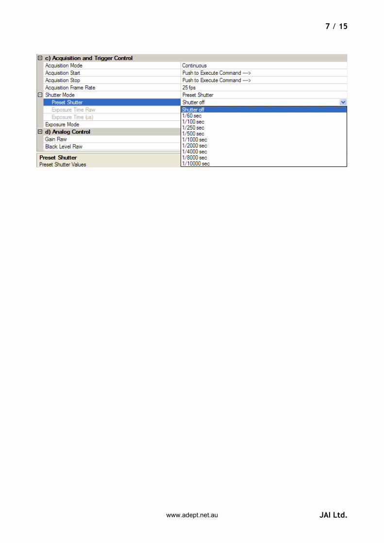
1) Preset Shutter: This is selecting an exposure time from a list of pre-configured exposure
time values (such as 1/60 sec, 1/100 sec). In order to select a Preset Shutter value then the
Shutter Mode has to be set to “PresetShutter”. See the image below with an example of
possible Preset Shutter values available for a Compact GigE Vision camera.
2) Exposure time in camera specific units: The exposure time is selected as a “raw” value.
These values have no “unit” defined.
3) Exposure time in microseconds: The exposure time can be set to a specific number of
microseconds. This exposure time is an integer value.
Note:
It is important to note that only one of the exposure time features will be enabled at a time. This
is controlled by the current Shutter Mode!
www.adept.net.au
7 / 15
JAI Ltd.
www.adept.net.au
8 / 15
JAI Ltd.
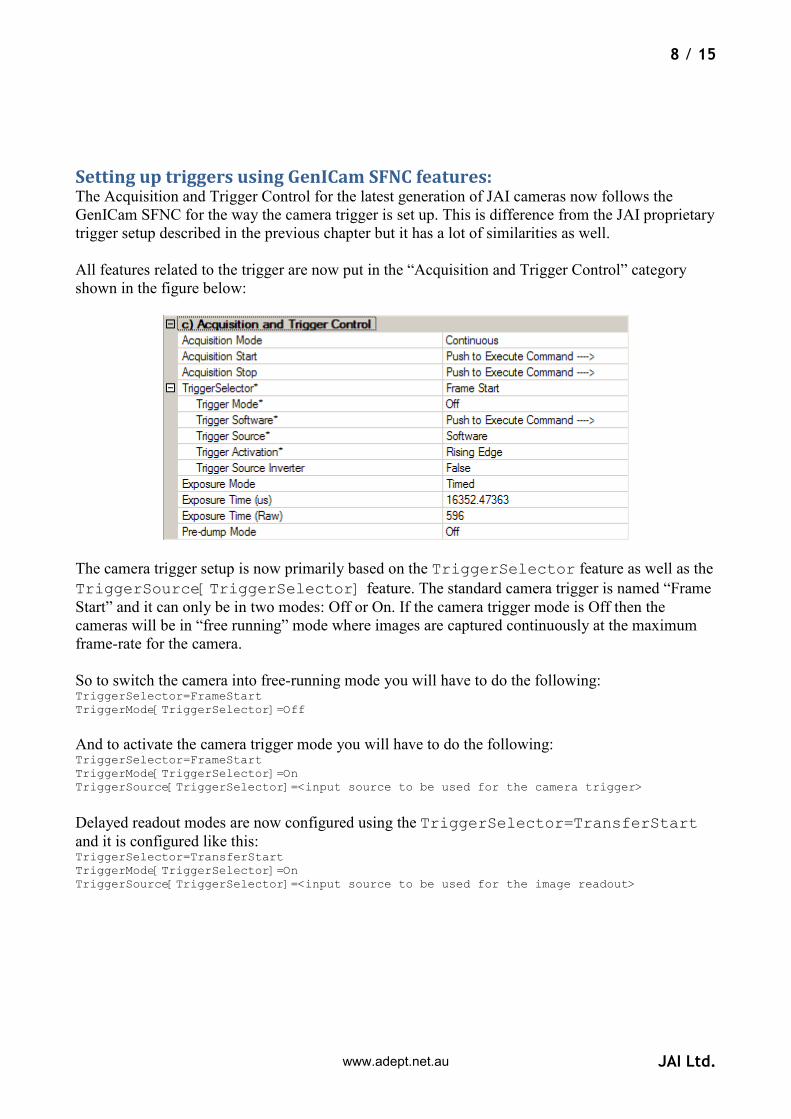
Setting up triggers using GenICam SFNC features: The Acquisition and Trigger Control for the latest generation of JAI cameras now follows the
GenICam SFNC for the way the camera trigger is set up. This is difference from the JAI proprietary
trigger setup described in the previous chapter but it has a lot of similarities as well.
All features related to the trigger are now put in the “Acquisition and Trigger Control” category
shown in the figure below:
The camera trigger setup is now primarily based on the TriggerSelector feature as well as the
TriggerSource[TriggerSelector] feature. The standard camera trigger is named “Frame
Start” and it can only be in two modes: Off or On. If the camera trigger mode is Off then the
cameras will be in “free running” mode where images are captured continuously at the maximum
frame-rate for the camera.
So to switch the camera into free-running mode you will have to do the following: TriggerSelector=FrameStart TriggerMode[TriggerSelector]=Off
And to activate the camera trigger mode you will have to do the following: TriggerSelector=FrameStart TriggerMode[TriggerSelector]=On TriggerSource[TriggerSelector]=<input source to be used for the camera trigger>
Delayed readout modes are now configured using the TriggerSelector=TransferStart
and it is configured like this: TriggerSelector=TransferStart TriggerMode[TriggerSelector]=On TriggerSource[TriggerSelector]=<input source to be used for the image readout>
www.adept.net.au

9 / 15
JAI Ltd.
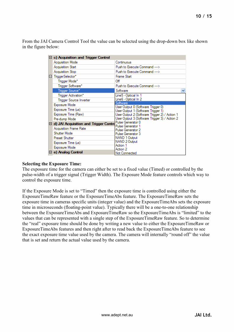
The TriggerSource[TriggerSelector] feature can be set to one of the following values:
GenICam feature name Display Name Description
Line5 Line5 - Optical In 1 External input port 1 is connected
Line6 Line6 - Optical In 2 External input port 2 is connected
Software Software The internal Software trigger
signal (from TriggerSoftware
command) is connected
UserOutput0 User Output 0 (Software
Trigger 0)
The internal user output signal 0
(SoftwareTrigger0 feature) is
connected
UserOutput1 User Output 1 (Software
Trigger 1)
The internal user output signal 1
(SoftwareTrigger1 feature) is
connected
UserOutput2 User Output 2 (Software
Trigger 2) / Action 1
The internal user output signal 2
(SoftwareTrigger2 feature) is
connected as well as the new
Action Command 1
UserOutput3 User Output 3 (Software
Trigger 3) / Action 2
The internal user output signal 3
(SoftwareTrigger3 feature) is
connected as well as the new
Action Command 2
PulseGenerator0 Pulse Generator 0 The internal Pulse Generator 0
signal is connected.
PulseGenerator1 Pulse Generator 1 The internal Pulse Generator 1
signal is connected.
PulseGenerator2 Pulse Generator 2 The internal Pulse Generator 2
signal is connected.
PulseGenerator3 Pulse Generator 3 The internal Pulse Generator 3
signal is connected.
NAND1Output NAND 1 Output The internal NAND-gate 1 signal
is connected.
NAND2Output NAND 2 Output The internal NAND-gate 2 signal
is connected.
Action1 Action 1 The new Action Command 1 is
connected
Action2 Action 2 The new Action Command 2 is
connected
NotConnected Not Connected No signal is connected
The “TriggerSource[TriggerSelector]” feature can be set from JAI SDK using the
following commands:
J_Camera_SetValueString(hCamera,“TriggerSelector”,<trigger to configure>); J_Camera_SetValueString(hCamera,“TriggerSource”,<new trigger signal to connect>);
www.adept.net.au
10 / 15
JAI Ltd.
From the JAI Camera Control Tool the value can be selected using the drop-down box like shown
in the figure below:
Selecting the Exposure Time:
The exposure time for the camera can either be set to a fixed value (Timed) or controlled by the
pulse-width of a trigger signal (Trigger Width). The Exposure Mode feature controls which way to
control the exposure time.
If the Exposure Mode is set to “Timed” then the exposure time is controlled using either the
ExposureTimeRaw feature or the ExposureTimeAbs feature. The ExposureTimeRaw sets the
exposure time in cameras specific units (integer value) and the ExposureTimeAbs sets the exposure
time in microseconds (floating-point value). Typically there will be a one-to-one relationship
between the ExposureTimeAbs and ExposureTimeRaw so the ExposureTimeAbs is “limited” to the
values that can be represented with a single step of the ExposureTimeRaw feature. So to determine
the “real” exposure time should be done by writing a new value to either the ExposureTimeRaw or
ExposureTimeAbs features and then right after to read back the ExposureTimeAbs feature to see
the exact exposure time value used by the camera. The camera will internally “round off” the value
that is set and return the actual value used by the camera.
www.adept.net.au
11 / 15
JAI Ltd.
Use Cases This chapter contains use cases that illustrate how to set up different trigger scenarios using both
JAI proprietary features and the SFNC features:
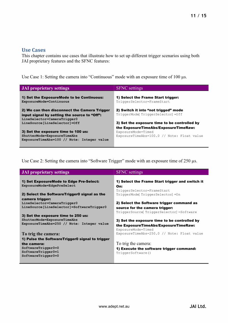
Use Case 1: Setting the camera into “Continuous” mode with an exposure time of 100 µs.
JAI proprietary settings SFNC settings
1) Set the ExposureMode to be Continuous: ExposureMode=Continuous
2) We can then disconnect the Camera Trigger
input signal by setting the source to “Off”: LineSelector=CameraTrigger0 LineSource[LineSelector]=Off
3) Set the exposure time to 100 us: ShutterMode=ExposureTimeAbs ExposureTimeAbs=100 // Note: Integer value
1) Select the Frame Start trigger: TriggerSelector=FrameStart
2) Switch it into “not trigged” mode TriggerMode[TriggerSelector]=Off
3) Set the exposure time to be controlled by
the ExposureTimeAbs/ExposureTimeRaw: ExposureMode=Timed ExposureTimeAbs=100.0 // Note: Float value
Use Case 2: Setting the camera into “Software Trigger” mode with an exposure time of 250 µs.
JAI proprietary settings SFNC settings
1) Set ExposureMode to Edge Pre-Select: ExposureMode=EdgePreSelect
2) Select the SoftwareTrigger0 signal as the
camera trigger: LineSelector=CameraTrigger0 LineSource[LineSelector]=SoftwareTrigger0
3) Set the exposure time to 250 us: ShutterMode=ExposureTimeAbs ExposureTimeAbs=250 // Note: Integer value
To trig the camera: 1) Pulse the SoftwareTrigger0 signal to trigger
the camera: SoftwareTrigger0=0 SoftwareTrigger0=1 SoftwareTrigger0=0
1) Select the Frame Start trigger and switch it
On: TriggerSelector=FrameStart TriggerMode[TriggerSelector]=On
2) Select the Software trigger command as
source for the camera trigger: TriggerSource[TriggerSelector]=Software
3) Set the exposure time to be controlled by
the ExposureTimeAbs/ExposureTimeRaw: ExposureMode=Timed ExposureTimeAbs=250.0 // Note: Float value
To trig the camera: 1) Execute the software trigger command: TriggerSoftware()
www.adept.net.au

12 / 15
JAI Ltd.
Use Case 3: Setting the camera into “Hardware Trigger” mode with a fixed exposure time of 500 µs.
JAI proprietary settings SFNC settings
1) Set ExposureMode to Edge Pre-Select: ExposureMode=EdgePreSelect
2) Select the GPIO_PortIn1* signal as the
camera trigger: LineSelector=CameraTrigger0 LineSource[LineSelector]=GPIO_PortIn1
3) Set the exposure time to 500 us: ShutterMode=ExposureTimeAbs ExposureTimeAbs=500 // Note: Integer value
* The GPIO input port name will depend on camera model and which physical input pin to be used for triggering
1) Select the Frame Start trigger and switch it
On: TriggerSelector=FrameStart TriggerMode[TriggerSelector]=On
2) Select the Line1* as source for the camera
trigger: TriggerSource[TriggerSelector]=Line1
3) Set the exposure time to be controlled by
the ExposureTimeAbs/ExposureTimeRaw: ExposureMode=Timed ExposureTimeAbs=500.0 // Note: Float value
* The line number will depend on camera model and which physical input pin to be used for triggering
Use Case 4: Setting the camera into “Hardware Trigger” mode where the exposure time is
controlled by the pulse-width of the external trigger signal.
JAI proprietary settings SFNC settings
1) Set ExposureMode to Pulse-Width Control: ExposureMode=PulseWidthControl
2) Select the GPIO_PortIn1* signal as the
camera trigger: LineSelector=CameraTrigger0 LineSource[LineSelector]=GPIO_PortIn1
* The GPIO input port name will depend on camera model and which physical input pin to be used for triggering
1) Select the Frame Start trigger and switch it
On: TriggerSelector=FrameStart TriggerMode[TriggerSelector]=On
2) Select the Line1* as source for the camera
trigger: TriggerSource[TriggerSelector]=Line1
3) Set the exposure time to be controlled by
the pulse-width of the input signal: ExposureMode=TriggerWidth
* The line number will depend on camera model and which physical input pin to be used for triggering
www.adept.net.au

13 / 15
JAI Ltd.
Use Case 5: Setting the camera into “Delayed Readout” mode with two external hardware signals
and with an exposure time of 100 µs.
JAI proprietary settings SFNC settings
1) Set ExposureMode to Delayed readout Edge
Pre-Select: ExposureMode=DelayedReadoutEPSTrigger
2) Select the GPIO_PortIn1* signal as the
camera trigger: LineSelector=CameraTrigger0 LineSource[LineSelector]=GPIO_PortIn1
2) Select the GPIO_PortIn2* signal as the
image readout trigger: LineSelector=CameraTrigger1 LineSource[LineSelector]=GPIO_PortIn2
3) Set the exposure time to 100 us: ShutterMode=ExposureTimeAbs ExposureTimeAbs=100 // Note: Integer value * The GPIO input port names will depend on camera model and which physical input pin to be used for triggering
1) Select the Frame Start trigger and switch it
On: TriggerSelector=FrameStart TriggerMode[TriggerSelector]=On
2) Select the Line1* as source for the camera
trigger: TriggerSource[TriggerSelector]=Line1
3) Select the image readout trigger and switch
it On: TriggerSelector=TransferStart TriggerMode[TriggerSelector]=On
4) Select the Line2 as source for the image
readout: TriggerSource[TriggerSelector]=Line2
5) Set the exposure time to be controlled by
the ExposureTimeAbs/ExposureTimeRaw: ExposureMode=Timed ExposureTimeAbs=100.0 // Note: Float value * The line number will depend on camera model and which physical input pin to be used for triggering
www.adept.net.au

14 / 15
JAI Ltd.
Use Case 6: Setting the camera into “Delayed Readout” mode with a Pulse Generator setting the
delay and with an exposure time of 100 µs.
JAI proprietary settings SFNC settings
1) Set ExposureMode to Delayed readout
Edge Pre-Select: ExposureMode=DelayedReadoutEPSTrigger
2) Select the GPIO_PortIn1* signal as the
camera trigger: LineSelector=CameraTrigger0 LineSource[LineSelector]=GPIO_PortIn1
3) Select the PulseGenerator0 signal as the
image readout trigger when it becomes Low: LineSelector=CameraTrigger1 LineSource[LineSelector]=PulseGenerator0 LineInverter[LineSelector]=ActiveLow
4) Set the exposure time to 100 us: ShutterMode=ExposureTimeAbs ExposureTimeAbs=100 // Note: Integer value
5) Setup PulseGenerator0 to be started by
the same input signal as the camera trigger
and to create a delay of 1 second before
reading out the image: ClockSource= MHz25 ClockPreScaler=2500 // 10KHz PulseGeneratorSelector=PulseGenerator0 PulseGeneratorLength=10001 // 1.0001s PulseGeneratorStartPoint=0 PulseGeneratorEndPoint=10000 // 1s pulse PulseGeneratorRepeatCount=1 // Only once PulseGeneratorClear=RisingEdge
6) Select the GPIO_PortIn1* signal as the
input to the PulseGenerator0: LineSelector=PulseGenerator0 LineSource[LineSelector]=GPIO_PortIn1 * The GPIO input port name will depend on camera model and which physical input pin to be used for triggering
1) Select the Frame Start trigger and switch it On: TriggerSelector=FrameStart TriggerMode[TriggerSelector]=On
2) Select the Line1* as source for the camera
trigger: TriggerSource[TriggerSelector]=Line1
3) Select the image readout trigger and switch it
On: TriggerSelector=TransferStart TriggerMode[TriggerSelector]=On
4) Select the PulseGenerator0 as source for the
image readout trigger when it becomes Low: TriggerSource[TriggerSelector]=PulseGenerator0 TriggerSourceInverter[TriggerSelector]=True
5) Set the exposure time to be controlled by the
ExposureTimeAbs/ExposureTimeRaw: ExposureMode=Timed ExposureTimeAbs=100.0 // Note: Float value 6) Setup PulseGenerator0 to be started by the
same input signal as the camera trigger and to
create a delay of 1 second before reading out the
image: ClockSource= MHz25 ClockPreScaler=2500 // 10KHz PulseGeneratorSelector= PulseGenerator0 PulseGeneratorLength=10001 // 1.0001s PulseGeneratorStartPoint=0 PulseGeneratorEndPoint=10000 // 1s pulse PulseGeneratorRepeatCount=1 // Only once PulseGeneratorClearActivation=RisingEdge PulseGeneratorClearSource=Line1
* The line number will depend on camera model and which physical input pin to be used for triggering
www.adept.net.au
15 / 15
JAI Ltd.
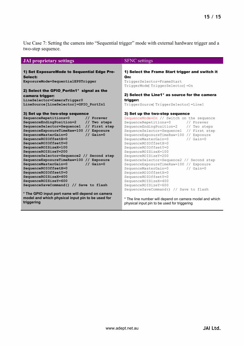
Use Case 7: Setting the camera into “Sequential trigger” mode with external hardware trigger and a
two-step sequence.
JAI proprietary settings SFNC settings
1) Set ExposureMode to Sequential Edge Pre-
Select: ExposureMode=SequentialEPSTrigger
2) Select the GPIO_PortIn1* signal as the
camera trigger: LineSelector=CameraTrigger0 LineSource[LineSelector]=GPIO_PortIn1
3) Set up the two-step sequence SequenceRepetitions=0 // Forever SequenceEndingPosition=2 // Two steps SequenceSelector=Sequence1 // First step SequenceExposureTimeRaw=100 // Exposure SequenceMasterGain=0 // Gain=0 SequenceROIOffsetX=0 SequenceROIOffsetY=0 SequenceROISizeX=100 SequenceROISizeY=200 SequenceSelector=Sequence2 // Second step SequenceExposureTimeRaw=100 // Exposure SequenceMasterGain=0 // Gain=0 SequenceROIOffsetX=0 SequenceROIOffsetY=0 SequenceROISizeX=400 SequenceROISizeY=600 SequenceSaveCommand() // Save to flash * The GPIO input port name will depend on camera model and which physical input pin to be used for triggering
1) Select the Frame Start trigger and switch it
On: TriggerSelector=FrameStart TriggerMode[TriggerSelector]=On
2) Select the Line1* as source for the camera
trigger: TriggerSource[TriggerSelector]=Line1
3) Set up the two-step sequence SequenceMode=On // Switch on the sequence SequenceRepetitions=0 // Forever SequenceEndingPosition=2 // Two steps SequenceSelector=Sequence1 // First step SequenceExposureTimeRaw=100 // Exposure SequenceMasterGain=0 // Gain=0 SequenceROIOffsetX=0 SequenceROIOffsetY=0 SequenceROISizeX=100 SequenceROISizeY=200 SequenceSelector=Sequence2 // Second step SequenceExposureTimeRaw=100 // Exposure SequenceMasterGain=0 // Gain=0 SequenceROIOffsetX=0 SequenceROIOffsetY=0 SequenceROISizeX=400 SequenceROISizeY=600 SequenceSaveCommand() // Save to flash
* The line number will depend on camera model and which physical input pin to be used for triggering
www.adept.net.au