different forensic tools on a single ssd and hdd, their ......yashwanth reddy kambalapalli st. cloud...
TRANSCRIPT

St. Cloud State UniversitytheRepository at St. Cloud State
Culminating Projects in Information Assurance Department of Information Systems
5-2018
Different Forensic Tools on a Single SSD andHDD, Their Differences and DrawbacksYashwanth Reddy KambalapalliSt. Cloud State University, [email protected]
Follow this and additional works at: https://repository.stcloudstate.edu/msia_etds
This Starred Paper is brought to you for free and open access by the Department of Information Systems at theRepository at St. Cloud State. It has beenaccepted for inclusion in Culminating Projects in Information Assurance by an authorized administrator of theRepository at St. Cloud State. For moreinformation, please contact [email protected].
Recommended CitationKambalapalli, Yashwanth Reddy, "Different Forensic Tools on a Single SSD and HDD, Their Differences and Drawbacks" (2018).Culminating Projects in Information Assurance. 59.https://repository.stcloudstate.edu/msia_etds/59

Different Forensic Tools on a Single SSD and HDD, Their Differences and Drawbacks
by
Yashwanth Reddy Kambalapalli
A Starred Paper
Submitted to the Graduate Faculty of
St. Cloud State University
in Partial Fulfillment of the Requirements
for the Degree
Master of Science
in Information Assurance
May, 2018
Starred Paper Committee:
Mark Schmidt, Chairperson
Paul Safonov
Balasubramanian Kasi

2
Abstract
With the increase in technology comes great innovations. One such transformation is changing
from Hard Disks to Solid State Drives. Solid State Drives generally known as SSD’s is a non-
volatile memory which became a key storage system nowadays. SSD's are nothing but a storage
device like Hard Disks but many times faster with a very much lower power consumption. They
are smaller in size and more efficient, the mechanism by which SSDs store and modify data is
intrinsically different from hard disk drives. Each innovation has its advantages as well as
drawbacks. When it comes to digital forensics working on SSD’s is relatively new. It has been a
challenge for the cyber-crime investigators ever since the evolution of SSD's, it was easy in hard
disks to retrieve deleted data but when it comes to SSD's, they can automatically retrieve or
alter data whenever they are connected to power even without an interface which results in
major evidence loss or contamination. There are different types of SSD's which do not function
similarly is also a challenge to a cybercrime investigator. The main purpose of this paper is to
describe the evolution of SSD's and creating image files of a single SSD and Hard Disk using
different forensic tools and comparing results. We create an evidence file and pass it to SSD and
HDD with multiple permutations and combinations, then we format the disks and create an
image file of both the disks to analyze using a forensic tool. We will also analyze how many
evidence files are being deleted completely from both the devices by comparing them with the
original number files we passed and the original hits we obtained while performing the analysis
on single evidence folder.

3
Table of Contents
Page
List of Tables ....................................................................................................................... 5
List of Figures ..................................................................................................................... 6
Chapter
I. Introduction ............................................................................................................. 11
Introduction ....................................................................................................... 11
Problem Statement ............................................................................................ 14
Objective of the Study ....................................................................................... 15
II. Background and Literature Review ......................................................................... 16
Digital Forensic ................................................................................................. 16
Digital Forensic Process .................................................................................... 19
Digital Forensic Tools ....................................................................................... 20
Evolution of SSD ............................................................................................... 25
Advantages of SSD ........................................................................................... 30
III. Methodology ........................................................................................................... 33
Hard Disk Drives ............................................................................................... 33
Solid State Drives .............................................................................................. 35
Hardware and Software Requirements .............................................................. 38
Summary ........................................................................................................... 39
IV. Data Presentation and Analysis ............................................................................... 40
Introduction ....................................................................................................... 40

4
Chapter Page
Data Presentation ............................................................................................... 40
Data Analysis .................................................................................................... 54
Summary ........................................................................................................... 60
V. Introduction, Results and Conclusion ..................................................................... 61
Introduction ....................................................................................................... 61
Results ............................................................................................................... 61
Conclusion ......................................................................................................... 84
References ........................................................................................................................... 85

5
List of Tables
Table Page
1. Results Obtained from Images of HDD in FTK ...................................................... 74
2. Results Obtained from Images of SSD in FTK ....................................................... 76
3. Comparing the Results Obtained in FTK ................................................................ 77
4. Results Obtained from Images of HDD in Autopsy ................................................ 82
5. Results Obtained from Images of SSD in Autopsy ................................................. 82
6. Comparing the Results Obtained in Autopsy .......................................................... 82

6
List of Figures
Figure Page
1. Solid state drives ..................................................................................................... 12
2. Digital forensic process ........................................................................................... 17
3. Digital forensics process step-by-step ..................................................................... 20
4. Digital forensic framework ..................................................................................... 22
5. X-Ways UI .............................................................................................................. 24
6. Encase UI ................................................................................................................ 25
7. SSD internal structure ............................................................................................. 26
8. V-NAND SSD ......................................................................................................... 28
9. Evolution of SSD ..................................................................................................... 29
10. Usage of SSD and HHD comparison ...................................................................... 30
11. Hard disk drive image ............................................................................................. 33
12. Hard disk internal structure ..................................................................................... 34
13. Solid state drives ..................................................................................................... 36
14. Evidence folders ...................................................................................................... 41
15. Evidence car folder .................................................................................................. 41
16. Evidence medicine folder ........................................................................................ 41
17. Evidence farm house folder ..................................................................................... 42
18. Evidence phone folder ............................................................................................. 42
19. Evidence laptop folder ............................................................................................. 42
20. Combined file size of the evidence, evidence thrashes, and junk file ..................... 43

7
Figure Page
21. Installation of HD shredder ..................................................................................... 44
22. Running HD shredder .............................................................................................. 44
23. Detecting both the drive on two different laptops ................................................... 45
24. Drive wiping process at random intervals in HDD and SSD .................................. 45
25. Successful completion of disk wiping using HD shredder ...................................... 46
26. Passing evidence ...................................................................................................... 46
27. Passing Evidence 1, Evidence 2 .............................................................................. 47
28. Passing Evidence 1, Evidence 3 .............................................................................. 47
29. Passing Evidence 1, Evidence 4 .............................................................................. 47
30. Passing Evidence 2, Evidence 3 .............................................................................. 48
31. Passing Evidence 2, Evidence 4 .............................................................................. 48
32. Passing Evidence 2, Evidence 4 .............................................................................. 48
33. Selecting the source evidence .................................................................................. 49
34. Creating the image of a folder ................................................................................. 49
35. Selecting the source path ......................................................................................... 50
36. Assigning name for unique identification ............................................................... 50
37. Assigning image destination ................................................................................... 51
38. Selecting the fragmentation size .............................................................................. 51
39. Processing of image creation ................................................................................... 52
40. Verifying results of the image created .................................................................... 52
41. Image summary for image ....................................................................................... 53

8
Figure Page
42. Image of evidence folder ......................................................................................... 53
43. Filling personal details of investigator .................................................................... 54
44. Adding image file to FTK toolkit ............................................................................ 55
45. Adding image file to analyze ................................................................................... 55
46. Evidence summary and add evidence ..................................................................... 56
47. Extracting the files from image ............................................................................... 56
48. Home page of FTK toolkit ...................................................................................... 57
49. Searching by the file names ..................................................................................... 57
50. Home page of forensic imager ................................................................................ 58
51. Selecting image to convert ...................................................................................... 58
52. Source of destination file forensic imager ............................................................... 59
53. Image converted and summary ................................................................................ 59
54. HDD connected to Laptop 1 .................................................................................... 61
55. Home screen of FTK ............................................................................................... 62
56. Selecting option from type of device ...................................................................... 62
57. Selecting HDD drive from image creation .............................................................. 63
58. Create image evidence item information ................................................................. 63
59. Selecting the destination for image of HDD ........................................................... 54
60. Create image destination path ................................................................................. 54
61. Selecting the type of image format .......................................................................... 55
62. Unique identification for the image file .................................................................. 55

9
Figure Page
63. Selecting the fragmentation size for image of HDD ............................................... 66
64. Verifying and starting the process of image creation .............................................. 66
65. Image creation of HDD at different intervals .......................................................... 67
66. Image created of HDD ............................................................................................ 67
67. SSD connected to second laptop ............................................................................. 68
68. Selecting the logical drive for DDS image creation ................................................ 68
69. Selecting SSD drive for image creation .................................................................. 68
70. Selecting the destination for image of SSD ............................................................. 69
71. Selecting the type of SSD image ............................................................................. 69
72. Selecting the fragmentation size for image of SSD ................................................ 69
73. Verifying and starting the process of image creation of SSD ................................. 70
74. Image creation of SSD at different intervals ........................................................... 70
75. Images created of SSD ............................................................................................ 71
76. Processing image 1 of HDD .................................................................................... 71
77. Files identified by searching keywords in image 1 of HDD ................................... 72
78. Results identified in image 1 of HDD ..................................................................... 72
79. Processing image 2 of HDD .................................................................................... 72
80. Results identified in image 2 of HDD ..................................................................... 73
81. Files identified by searching keywords in image 2 of HDD ................................... 73
82. Adding evidence to analyze results of SSD ............................................................ 84
83. Processing Image 1 of SSD ..................................................................................... 84
10
Figure Page
84. Processing image 2 of SSD ..................................................................................... 75
85. Processing image 3 of SSD ..................................................................................... 75
86. Processing image 4 of SSD ..................................................................................... 76
87. Processing image 5 of SSD ..................................................................................... 76
88. Difference in results identified by number of files in FTK ..................................... 77
89. Difference in results identified by number of Hit in FTK ....................................... 78
90. New case information .............................................................................................. 78
91. Set case number and examiner ................................................................................ 79
92. Creating a case database .......................................................................................... 79
93. Creating new text index ........................................................................................... 80
94. Selecting type of data source ................................................................................... 80
95. Browsing image file ................................................................................................ 81
96. Configure ingest modules ........................................................................................ 81
97. Difference in results identified by number of files in autopsy ................................ 83
98. Difference in results identified by number of Hit in autopsy .................................. 83

11
Chapter I: Introduction
Introduction
Solid State Drives generally known as SSD’s are non-volatile memory which became a
key storage system nowadays, SSD can also be called as Solid State Disk, use of SSD is simple
enough and for many purposes it can be used as if it was a normal hard disc but many times
faster and with a very much lower power consumption, they are smaller in size and more
efficient, it stores data in a persistent manner and Solid State Drives doesn't have any disks in a
traditional manner that are spinning which stores data with two heads read and write. SSD in
place of this mechanical device consists of integrated circuits and semiconductors which are
used as memory devices. SSD does not have any magnetic tapes or optical storage media like in
Hard Disks (Rouse, 2016) .
Input and output operational performance is relatively high when compared to Hard
drives which resulted in rapid growth in the use and evolution of SSD. HDDs have much
greater random access and read access latency compared to SSDs, this lower random access and
read access makes the SSDs reliable and efficient for both heavy read and random workloads.
The ability of SSD to read data directly from the cell location is the reason for the lower latency
(Rouse, 2016).
Flash memory based Solid State Drives (SSD), an emerging storage technology, plays a
critical role in revolutionizing the storage system design. Such a fundamental difference makes
SSD capable of providing one order of magnitude higher performance than rotating media and
makes it an ideal storage medium for building high-performance storage systems. Due to the
relatively low capacity and higher price which can accommodate more data compared to a
12
typical HDD will (Chen, Koufaty, & Zhang, 2016). As our computer is equipped with chips and
motherboard comes with some of the chips which are called as system memory which is also
called as RAM, is used to store and process data when a system is working, this is known as
Volatile memory, the word volatile is used because the memory that is stored and accessed is
removed as soon as the system is turned off or shut down. The microchips that are used in the
Solid State Drives are called as the Non-Volatile memory because data will be stored in the
device even after the system is turned off (Harris, 2015). Chips of SSD are not located on the
motherboard. These chips are stored in another part of the computer, we can remove the hard
drive of your laptop and replace it with a solid-state drive, without affecting any other essential
components (Harris, 2015).
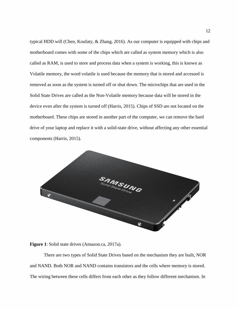
Figure 1: Solid state drives (Amazon.ca, 2017a).
There are two types of Solid State Drives based on the mechanism they are built, NOR
and NAND. Both NOR and NAND contains transistors and the cells where memory is stored.
The wiring between these cells differs from each other as they follow different mechanism. In

13
NOR the cells are wired in a parallel mechanism as it contains more complex structure and
bigger structure and has more wires to connect and NAND these cells are arranged in a series
mechanism where the complexity is much less as it contains fewer wires and they are packed on
a chip with great density (Harris, 2015) .
Because of this complex arrangement the NAND devices are cheaper and much used as
the read and write operations are performed with a great speed. These features make NAND
devices much more predominant memory storage device in Solid State Drives. NOR devices are
mostly used when the data has read-only permission where the read access is much faster
compared to NAND and the data is stored in a low density. Based on the above features of a
solid-state drive, it can be defined “NAND flash to provide non-volatile, rewritable memory.”
(Harris, 2015).
Digital forensics plays an import role in the investigation due to the increase in the use
of computers. Usage of computers has been predominantly increased in everyday human life
which also involves criminal activities in some form that makes digital forensics role important
in the investigation. Every crime nowadays will leave a trace of evidence in digital form, for
example, usage of mobile phones, laptops, internet etc. finding these evidences and dig down to
conclude will involve few methods and procedures. Digital forensic involves four steps in every
investigation (Garfinkel, 2013).
Different forensic tools working on a single SSD, comparing the results of forensic tools
on an SSD and the challenges faced by the forensic investigators are discussed in this paper.

14
Problem Statement
Due to increase of crime in both criminal, digital and civic activities, it has been a
bottleneck situation for the investigators. As every crime nowadays involve electronic devices
in some form whether it can be a direct hacking or a crime where an electronic device has been
recovered as an evidence, investigators are more focusing on forensic science to know the
motive of the crime or mindset of an individual.
There are many cases which can be solved using digital forensics. Technology is
updating every day and use of latest devices has been increasing rapidly which makes
investigators job a little more difficult compared to past. As people are updated with the
technology and latest devices even investigators must focus more on the latest devices how they
work and internal functioning of the device.
Digital forensic investigators more focus on traditional ways such as working on the
hard drives as most of the devices are equipped with them from the past few decades and certain
ways to drill down and find the evidence traditionally. However, these mechanisms cannot be
applied on SSDs as they follow different storage mechanism and accessing data.
The difficulties faced by the forensic team to investigate on SSDs are discussed in this
paper, this paper will also discuss what are the difficulties faced by the investigators when
working on SSD compared to hard drives, different forensic tools work differently based on the
budget allocated and the type of tool used to investigate. Each forensic tool will perform the
different operation based on the capacity.

15
Objective of the Study
1. The main objective of the study is to find out what are the challenges faced by the
forensic investigators for finding evidence in SSD's.
2. This study will also compare the results obtained from different forensic tools on a
single SSD and HDD.

16
Chapter II: Background and Literature Review
Digital Forensic
Digital forensics plays an import role in the investigation due to the increase in the use
of computers. Usage of computers has been predominantly increased in everyday human life
which also involves criminal activities in some form that makes digital forensics role important
in the investigation. Every crime nowadays will leave a trace of evidence in digital form, for
example, usage of mobile phones, laptops, internet etc. finding these evidences and dig down to
conclude will involve few methods and procedures. The process of uncovering and finding the
evidence stored in any kind of an electronic device is called as “Digital Forensics” (Garfinkel,
2013).
Digital forensic investigators face a challenging role in computers when it comes to data
analysis and cybersecurity. Forensic science is very much different from digital forensics as the
data in a system can be changed and there is a vast data to analyze as well as the breakdown of
everything to find out evidence, the process of digital forensics is never easy and time-
consuming as it may take months to years based on the complexity. Digital forensics nowadays
is playing a major role in the investigation, it is acting as a breakpoint where it leads to a
conclusion or gives a major hint in any crime. Digital forensics is also playing a major role in
border security in scanning the emails and personal electronic equipment to ensure security. A
digital forensic investigator must understand data and make sense of data found in a device and
it is a very difficult task.

17
Figure 2: Digital forensic process (Azemovic, 2010).
Digital forensics in a real world serves two purposes each differ but they are in common
with the investigation. First, an electronic device contains an evidence of a crime that occurred
in a real world, due to the complexity of data in computers it made hard for the forensics team
to analyze data on computer storage device than that of a paper record. For example, Bernard
Madoff who made a financial scam in 1980, kept track of all the records of his victims on an
IBM computer. Investigators have found the data using some tools back in those days to analyze
data on his system and provide evidence of his crime. Suspects in a murder case generally have
an electronic device involved in one way or the other. Digital forensics has now become part of
every criminal as well as civil crime investigations (Garfinkel, 2013).
The second class is that a crime which involves the complete use of a system where a
person is involved in a crime using a computer or an electronic device, hacking into other
system and stealing data is one example of this class, here digital forensics plays a major part in
the investigation. Dealing with these crimes it is very hard for a forensic investigator without a
tool to analyze user data found in a hacker's laptop. Digital forensics is typically hard to analyze
on the windows system as all the log files are hard to analyze manually and the junk data or the
unwanted data that is present on the computer makes an investigation much more difficult than
18
usual, this also helps investigator to recover the data that has been deleted in the past using these
log files and the data recovery process. Search history can be found in the system which can
lead to a breakthrough in the investigation to draw a conclusion. These files will give an idea of
a state of mind of a criminal. When it comes to the evidence like letters, photos can be
submitted to the lawyers and judges. For example, a digital camera shows that it has around n
images, but expert examination can retrieve that it has (n + y) images where y are the images
deleted or erased, a person who delete or erase an image think it has been deleting permanently
but data is never erased completely, it is stored in slack space (Garfinkel, 2013).
As the digital forensics consider the past and recover the data that has been deleted, this
can also be applied to network security to check the intrusions and hacking. This is done not
only to find a criminal but to find the loopholes in the network and to cover the holes in the
system. Digital forensics also involves in finding data from the damaged disks or reformed. For
example, In May 2006 a laptop and external hard drive that contains data of millions of veterans
and military personnel have been stolen from military affairs official. After that laptop and hard
disk were recovered the investigators used tools to check the data present in it and concluded
that the files present on the hard drive were not affected or in fact, they are not viewed at all
(Garfinkel, 2013). Digital forensics rely on the tools and forensic kits for investigation. It
follows a step-by-step procedure in identifying the evidence, each evidence is analyzed in a
different form such as a device found in a murder crime is investigated in a different way when
it comes to a device found in a burglary. Investigation procedure is same, but the approach
differs from each other. Before a device is analyzed it must be recovered properly and set to a
state that the data present in the device is not fabricated. When the data are not properly handled

19
when the data present in the device can be altered leading to a false conclusion. Modern day
devices had memory card and drives which store data in sectors generally 512 to 4096 bytes. A
sector is the smallest part of a memory device where the actual data is stored. Each sector in the
device has an id or a unique identifier called as “Sector Identification Number” or “Logical
Block Address”. Metadata is stored in some sectors where the data about the data is stored.
RAM is also identified during the forensic process where an image is created to work on it as
data in RAM will be erased as soon as the system is turned off (Garfinkel, 2013).
Digital Forensic Process
Digital Forensic process generally involves four steps they are preservation, overview,
analysis, and reporting.
Preservation. This step focuses more on documentation and prevention of the evidence
altering, in this step the device that is recovered by the forensic team will be preserved so that
the data is not fabricated or changed. An image file is created for the device and the hash value
is generated to validate the evidence in future if it is changed or not. This is the crucial step in
the digital forensic process. (Dennon, 2016)
Overview/examination. The second step in the digital forensic process is called as
overview or examination, here the hash value that is created for the device is checked and the
image file that is generated is checked if it is successfully generated. The digital image format is
generated (for example, image.EO1 file) (Dennon, 2016).
Analysis. The Third step in digital forensic is called an analysis where the actual work
on the devices takes place which includes the process of user activity analysis which means log
file analysis and browser history, deleted file recovery, retrieving the deleted files from the disk

20
and keyword searching. It takes more time and effort in the entire forensic process (Dennon,
2016).
Reporting. Reporting is the final step in the digital forensic process where the evidence
that is collected after the analysis is subjected to the conclusion and a human interactive written
format is generated to present it in a courtroom or for the officials (Dennon, 2016).
Figure 3: Digital forensics process step-by-step (Janorkar, 2015).
Digital Forensic Tools
Digital Forensics require tools and kits to work on the device, there are many tools
which are paid as well as open source, based on the purpose and the budget the tool used varies
from case to case or the department it is investigating. The computer forensic tools can be
classified as follows:
1. Disk and data capture tools
2. File viewers
3. File analysis tools
4. Registry analysis tools

21
5. Internet analysis tools
6. Email analysis tools
7. Mobile devices analysis tools
8. Mac OS analysis tools
9. Network forensics tools
10. Database forensics tools
Various forensic tools are available in the market:
Forensic tool kit. Forensic Tool Kit also known as FTK is a computer forensics
software developed by Access Data. It is used in the digital investigation of hard drives, it
creates an image file using FTK Imager, investigators work on the image file to find the
evidence and such as deleted emails, deleted images, files. FTK imager creates an image file
where it saves the hard disk data to be referenced in future if any changes are made to the hard
drive data. A hash value is also generated to check for the future reference (wiki, 2017).
FTK allows handling huge data as it follows database-driven architecture. FTK has the
flexibility of built-in visualization tools and detects images which help in reporting the relevant
evidence that is found in an investigation. FTK has a feature of correlating data from different
sources which include SSDs or hard drives, mobile phones, and other internet related devices. It
reduces the investigation time which makes it a most preferred forensic tool (AccessData,
2017). FTK has features like Rainbow hashing tables and PORT.

22
Digital Forensic Framework. Digital Forensic Framework is a platform that is
developed for the forensics, it has a user interface and is an open source tool available in the
market, it is so user-friendly that anyone can use it without any trouble.
Figure 4: Digital forensic framework (Tools, 2014).
It can be used by both the digital forensic professionals as well as the beginners without
any trouble. It can be used for multiple purposes such as digital chain of custody for accessing
both the local and remote devices, for the forensics of both Windows operating system and
Linux operating system. It also recovers the deleted data or the hidden files from a hard drive
(Shankdhar, 2017). It has software write blocker which prevents from data manipulation or
modification and has a cryptographic hash value calculator which is used for the future

23
reference if the data is modified or not. It has the flexibility to read RAW, AFF and Encase
EWF formats, it is also VMware compatible, it processes local files, binary files, and
penetration testing (S.A.S., 2017).
Open Computer Forensic Architecture. Open Computer Forensics Architecture
(OCFA) is a digital forensic tool, it is a popular open source framework available in the market.
This was developed on the Linux platform and uses PostgreSQL for data storage. It was built by
the police agency for digital forensics process of automation (Shankdhar, 2017).
CAINE. CAINE is also called as Computer Aided Investigation Environment is
developed on the Linux platform which is created mainly for digital forensics. It is an open
source tool available in the market (Shankdhar, 2017).
X-Ways Forensic tool. X-Ways Forensics is a digital forensic tool used for the
advanced options. It is based on the Windows platform where it works on almost all the
windows operating system. It claims to not be very resource hungry and to work efficiently.
some of the features are listed below (X-Ways, 2017a).
Disk imaging and cloning, Ability to read file system structures inside various image
files. It supports most of the file systems including FAT12, FAT16, FAT32, exFAT, TFAT,
NTFS, Ext2, Ext3, Ext4, Next3®, CDFS/ISO9660/Joliet, UDF.
Automatic detection of deleted or lost hard disk partition, Various data recovery
techniques and powerful file carving, Bulk hash calculation, Viewing and editing binary data
structures using templates, Easy detection of and access NTFS ADS, Well maintained file
header, Automated activity logging, Data authenticity, Complete case management, Memory
and RAM analysis, Gallery view for pictures, Internal viewer for Windows registry file,
24
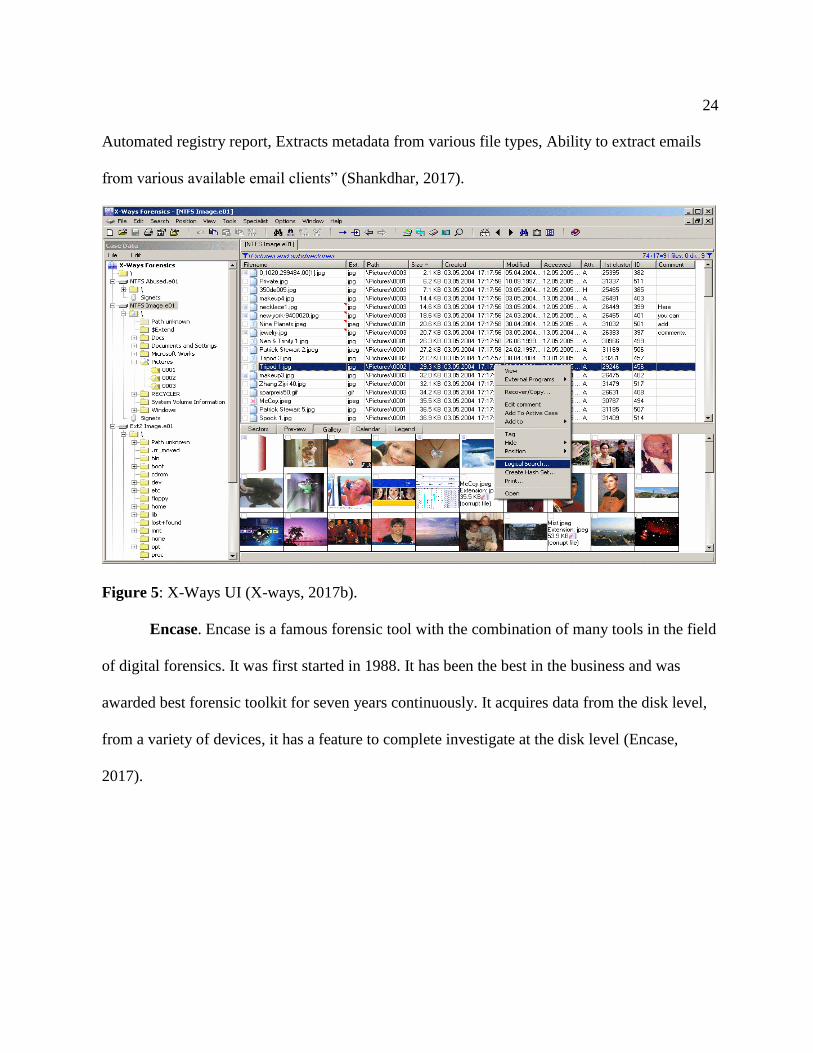
Automated registry report, Extracts metadata from various file types, Ability to extract emails
from various available email clients” (Shankdhar, 2017).
Figure 5: X-Ways UI (X-ways, 2017b).
Encase. Encase is a famous forensic tool with the combination of many tools in the field
of digital forensics. It was first started in 1988. It has been the best in the business and was
awarded best forensic toolkit for seven years continuously. It acquires data from the disk level,
from a variety of devices, it has a feature to complete investigate at the disk level (Encase,
2017).

25
Figure 6: Encase UI (Mizota, 2015).
Evolution of SSD
The Evolution of SSD started nearly 40 years back where it was called Solid State Disk.
First SSD was built in 1976 with a name Bulk Core. It was 19inches wide and 15.75 inches tall,
1 TB of this would cost about $152 billion in current day currency (Edwards, 2012).

26
Figure 7: SSD internal structure (Amazon.ca, 2017b).
In 1978, STC (Storage Technology Corporation) introduced 4305 cabinet which is 45
MB storage facility. It has dual controller cards which would cost around $400000 and $1.5
Million equivalent to present-day currency. It was 52% cheaper cost compared to IBM drum
storage (Edwards, 2012).
In 1979, Intel introduced 1 MB bubble memory chip which is called as 7110. This cost
around $895 for 128KB. In 1982, Apple 2 ram was launched Nolan Bushnell's toy company
Axlon, it would cost about $1395 which can store up to 320KB, as the data in this device is
stored in RAM chips a battery is included which can run on a 3hour rechargeable battery
(Edwards, 2012).
Later in 1982, a new issue advertisement was given on Byte magazine with 256KB
RAM developed which costs around $800. Axlon was a company more focused on developing
27
SSD for computer, in 1983 it developed a 1 MB storage which developed based on 256KB
configuration costs around $1095 (Edwards, 2012).
In 1988, a first flash drive was developed by Digipro, it could hold up to 16MB of data,
it came out in 1990 in 4 different models with the capacity of 2MB, 4MB, 6MB, and 8 MB
which cost around $5000. In 1989M-systems an Israeli based company developed first flash
drive, but it did not release it till 1995 which made the flash disk from Digipro world’s first
SSD. Even after 1990, the flash memory was still rare and costly, they are limited to servers
where data access speed is high. The series of 5.25-inch SCSI-based drives shipped in capacities
of 107MB ($13,999) to 428MB ($47,099). The faster series offered capacities from 120MB
($40,000) to 1GB ($135,000) (Edwards, 2012).
In 1996, Newer Tech Dart Drive and ATTO Silicon Drive 2 which could store up to
2.6GB of data would cost in thousands of dollars as they were intended for the high-end use
only where they are used only when the data processing time should be less. As we discussed
earlier all the SSD’s were equipped with a battery not to lose data when there is a power loss.
This device is called as the workstation SSD which is much faster compared to nowadays hard
drives with 0.02ms of access time (Edwards, 2012).
In 1995, M-Systems introduced fastest flash drive called Fast Flash Disk, it is small with
3.5 inches, it comes with memory accommodation of 16MB to 896MB and costs around $10000
per a drive, as they are costly it is mostly used in military and aeronautical applications, for the
next 10 years M-Systems continuously developed SSD’s with more capacity, high speed, and
less cost (Edwards, 2012).
28
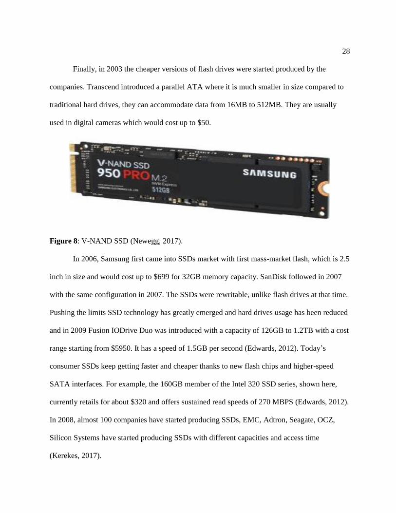
Finally, in 2003 the cheaper versions of flash drives were started produced by the
companies. Transcend introduced a parallel ATA where it is much smaller in size compared to
traditional hard drives, they can accommodate data from 16MB to 512MB. They are usually
used in digital cameras which would cost up to $50.
Figure 8: V-NAND SSD (Newegg, 2017).
In 2006, Samsung first came into SSDs market with first mass-market flash, which is 2.5
inch in size and would cost up to $699 for 32GB memory capacity. SanDisk followed in 2007
with the same configuration in 2007. The SSDs were rewritable, unlike flash drives at that time.
Pushing the limits SSD technology has greatly emerged and hard drives usage has been reduced
and in 2009 Fusion IODrive Duo was introduced with a capacity of 126GB to 1.2TB with a cost
range starting from $5950. It has a speed of 1.5GB per second (Edwards, 2012). Today’s
consumer SSDs keep getting faster and cheaper thanks to new flash chips and higher-speed
SATA interfaces. For example, the 160GB member of the Intel 320 SSD series, shown here,
currently retails for about $320 and offers sustained read speeds of 270 MBPS (Edwards, 2012).
In 2008, almost 100 companies have started producing SSDs, EMC, Adtron, Seagate, OCZ,
Silicon Systems have started producing SSDs with different capacities and access time
(Kerekes, 2017).

29
Figure 9: Evolution of SSD (ESSD Embedded, 2017)
In 2017, Crossbar has announced that it is working on an 8MB ReRAM, Intel also
started working on the future of the storage devices and day by day all the personal computers
and laptops have been started equipped with the modern day SSDs with much more capacity
and faster access speed. SSD is now available in many capacities ranging to 16TB and it is said
to be increased to 40Tb by 2017 (Kerekes, 2017).
The capacity of SSD is said to be increased to 128TB by the end of 2018 and will
continue growing in future thereafter. SSD has made a great revolution in both size and storage
capacity in the digital world (Humphries, 2017).
30
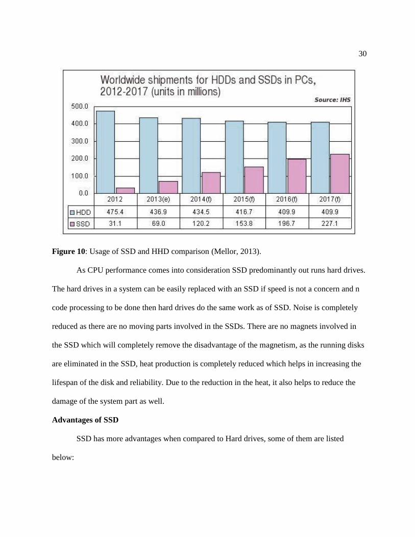
Figure 10: Usage of SSD and HHD comparison (Mellor, 2013).
As CPU performance comes into consideration SSD predominantly out runs hard drives.
The hard drives in a system can be easily replaced with an SSD if speed is not a concern and n
code processing to be done then hard drives do the same work as of SSD. Noise is completely
reduced as there are no moving parts involved in the SSDs. There are no magnets involved in
the SSD which will completely remove the disadvantage of the magnetism, as the running disks
are eliminated in the SSD, heat production is completely reduced which helps in increasing the
lifespan of the disk and reliability. Due to the reduction in the heat, it also helps to reduce the
damage of the system part as well.
Advantages of SSD
SSD has more advantages when compared to Hard drives, some of them are listed
below:
31
1. Access Time: Access time of an SSD is much more efficient when compared to hard
drive as it is equipped with the memory cells as in case of a Ram it is faster
comparatively. An SSD has access speeds of 35 to 100 microseconds, which is
nearly 100 times faster. This faster access speed means programs can run more
quickly, which is very significant, especially for programs that access large amounts
of data often like your operating system (Computer Hope, 2017a).
2. Price: The price of an SSD is relatively high due to the memory components used in
the SSD. The relatively high price of an SSD is the reason we do not find higher
capacity storage device in modern computers. The storage capacity of an SSD
equipped system is in GB when it is in TB for a hard drive equipped systems, but the
storage done in them are relatively same (Computer Hope, 2017a).
3. Reliability: As we know that the SSD does not have any moving parts we can say
that it is more reliable due to the other advantages of an SSD like capacity, noise,
heat, and magnetism (Computer Hope, 2017a).
4. Capacity: The price range of the SSD is relatively high when compared to the HDD
but relatively 512GB of memory is sufficient for the user when compared to 1TB of
a hard drive (Computer Hope, 2017a).
5. Power: The SSD uses less power when compared to HDD as the utilization of
power for the extra components are eliminated in SSD, this means that it utilizes less
power which in turn reduces the power bills and the battery life of the system will be
improved and can be utilized for another purpose (Computer Hope, 2017a).
32
6. Noise: With no moving parts SSD generates no noise. There is no disk running to
access data and no pointers are involved which makes reduces the noise concept.
7. Size: Size of an SSD is less compared to hard drive making them portable and due to
the reduction in the part it is relatively small. It is available in different sizes and
shapes. SSD is available in 2.5", 1.8", and 1.0", increasing the available space
available in a computer, especially a desktop or a server (Computer Hope, 2017a).
8. Heat: Because there are no moving parts and due to the nature of flash memory, the
SSD generates less heat, helping to increase its lifespan and reliability (Computer
Hope, 2017a).
9. Magnetism: SSD is not affected by magnetism. As SSD do not rely on the magnetic
disks and pointer to write data there are no concepts of magnetism in SSD
(Computer Hope, 2017a).

33
Chapter III: Methodology
Hard Disk Drives
A general computer has different storages spaces or devices among which Hard Disk has
the most memory space. It is considered as the main and the largest storage space in a physical
computer. Most important data are stored in Hard disks such as the Operating system, drivers,
system related files etc. As we know the program files reside in C drive which is nothing but the
Hard Disk in general (Fisher, 2017).
Figure 11: Hard disk drive image (LifeWire, 2017).
There are many competitors in HDD manufacturing among them Seagate, Western
digital, Samsung, Kingston etc. are some popular manufacturers. It comes in different sizes and
shapes. Some are mounted inside CPU or Laptops and some can be connected externally. The

34
cables used to connect the motherboard to the Hard disk are identified as two types based on the
variant SATA and PATA (Fisher, 2017).
How data is read in Hard Drive. A Disk Controller is used to read and write data to
the Hard Drives. It will instruct the Hard drive how to perform an operation like reading a file,
writing to a file, accessing a file location. Once FAT of a hard drive is determined then the disk
controller will instruct the actuator to align the read or write head by moving the read write arm.
Files are not stored in sequential memory locations and are scattered in different places of hard
disk thus the actuator and disk controller help in accessing the files (Computer Hope, 2017b).
Data is stored in hard drives magnetically which means it is stored and then retrieved
using magnetic disks and magnetic polarities.
Figure 12: Hard disk internal structure (Evan Amos, 2017).

35
Solid State Drives
Solid State Drives is a solid-state storage device that uses an integrated circuit assembly
as a memory to store data persistently. SSD’s do not have any moving mechanical components.
Solid State Drives uses a semiconductor chip, not magnetic media for storing data. Over the
past few decades, there has been a considerable amount of work being done in the field of
computers hardware. Even though the computer technology has been constantly improving and
evolving we rarely experience that feeling where we sit back and say, “wow that’s amazing”. It
is very rare to find a computer upgrade that would single-handedly transform our desktop
experience. We might be replacing a monitor with the latest led technology, upgrade our video
card for the best gaming experience, or install an additional RAM for faster processing.
However, the experience would feel the same at the end. But when there is a switch from hard
drive to Solid State Drives suddenly everything is fast (Aaronson, 2008).
For understanding the SSD Technology, we would need to understand the basic
overview of computer architecture. To make it simple, the computer’s memory architecture is
being divided into three sections namely cache, memory, and hard disk. Each section has a
critical function that determines the way they operate.
Cache is the innermost memory unit. Cache is used as a sort of playground for doing all
calculation and procedures as the computer operates. The data access is instantaneous, electrical
pathways to the cache are the shortest because the cache is mandatory. Memory is the middle
ground for computer known as RAM, Random Access Memory. RAM is the place where
information is being stored related to processes running on your machine and active programs.
Access to the memory is slow when compared to that of cache. A hard disk is a place where

36
everything is being stored for performance. Hard disk stores all our configuration files,
programs, music files, documents, and more. When a file is needed to be accessed or when we
need to run a program it needs to be loaded from the hard disk and then into the memory
(Evans, 2012).
To understand the functioning of an SSD, we first need to know the two most important
parts: The controller and NAND flash memory. These components along with few others are
being placed on a PCB known as printed circuit board which is being housed in a casing known
as SSD.
Controller. Controller is an embedded processor that bridges the flash memory
components to host i.e. computer. The controller executes the codes that are provided by the
SSD’s firmware, i.e., the mini operating system to fulfill data requests received from the host.
The controller would decide how SSD would perform and the features it offers. The popular
functions and features decided by the controller include reading, writing, error checking,
erasing, garbage collection, encryption, wear-levelling, overprovisioning, and RAISE (Seagate,
2012).
Figure 13: Solid state drives (Ngo., 2013).
37
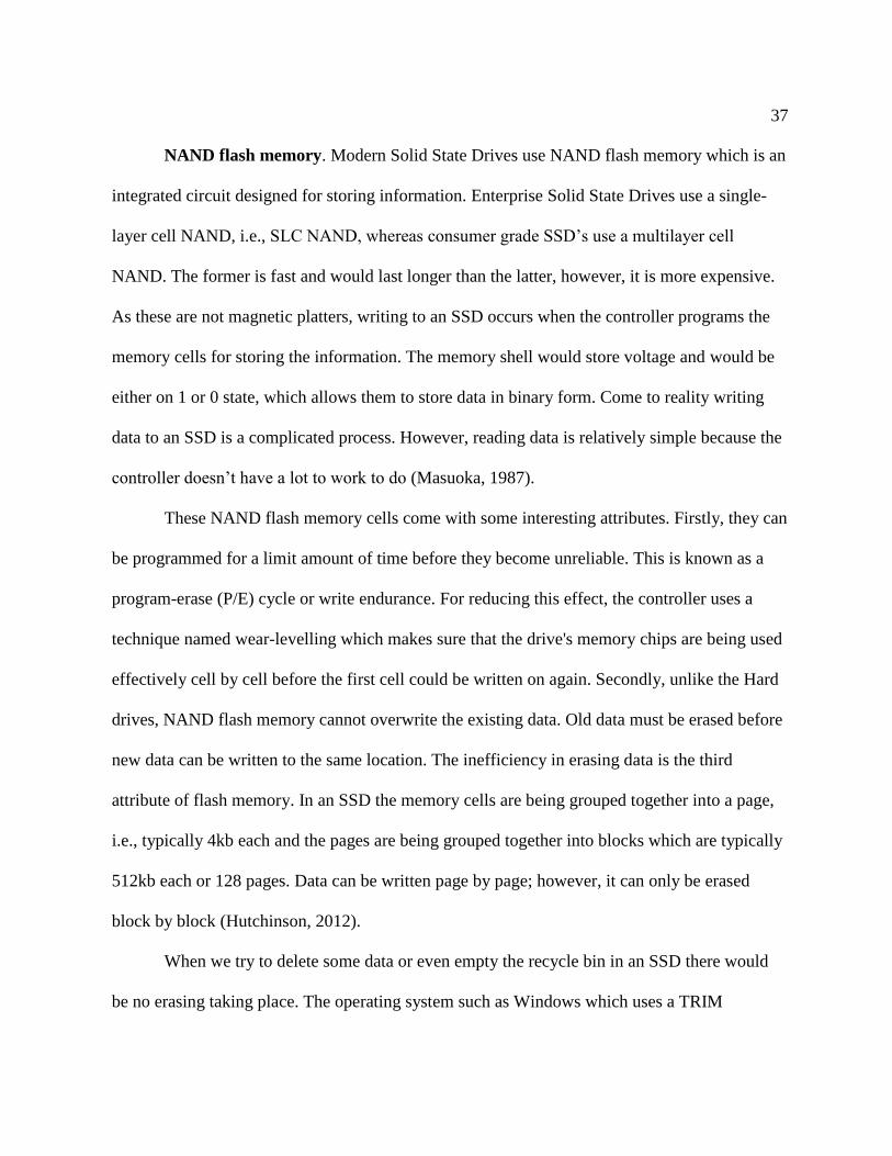
NAND flash memory. Modern Solid State Drives use NAND flash memory which is an
integrated circuit designed for storing information. Enterprise Solid State Drives use a single-
layer cell NAND, i.e., SLC NAND, whereas consumer grade SSD’s use a multilayer cell
NAND. The former is fast and would last longer than the latter, however, it is more expensive.
As these are not magnetic platters, writing to an SSD occurs when the controller programs the
memory cells for storing the information. The memory shell would store voltage and would be
either on 1 or 0 state, which allows them to store data in binary form. Come to reality writing
data to an SSD is a complicated process. However, reading data is relatively simple because the
controller doesn’t have a lot to work to do (Masuoka, 1987).
These NAND flash memory cells come with some interesting attributes. Firstly, they can
be programmed for a limit amount of time before they become unreliable. This is known as a
program-erase (P/E) cycle or write endurance. For reducing this effect, the controller uses a
technique named wear-levelling which makes sure that the drive's memory chips are being used
effectively cell by cell before the first cell could be written on again. Secondly, unlike the Hard
drives, NAND flash memory cannot overwrite the existing data. Old data must be erased before
new data can be written to the same location. The inefficiency in erasing data is the third
attribute of flash memory. In an SSD the memory cells are being grouped together into a page,
i.e., typically 4kb each and the pages are being grouped together into blocks which are typically
512kb each or 128 pages. Data can be written page by page; however, it can only be erased
block by block (Hutchinson, 2012).
When we try to delete some data or even empty the recycle bin in an SSD there would
be no erasing taking place. The operating system such as Windows which uses a TRIM
38
command would just mark the data that you wanted to erase as invalid or stale page by page.
However, the actual erasing is being done only when the user writes new data to the drive. So,
until and unless you are using the SSD drive for the first time there would be no writing to that
drive that happens without erasing taking place first. This would result in a controller having to
do something known as garbage collection while writing data to SSD. Wear leveling, and
garbage collection would cause the data to be re-written on SSD from one place to another with
a phenomenon called as write amplification.
Drawbacks of SSD. The main problem behind SSDs is inherent in the flash memory,
i.e., it could sustain only a finite number of writes before it dies. There is a lot of science which
goes in to explain the phenomenon behind this, but it suffices to say that when an SSD has used
the electrical charges within the cells must be periodically reset. Unfortunately, the electrical
resistance increases slightly during every reset which increases the voltage necessary to write in
a cell. The voltage becomes so high that the cell becomes useless. Thus, there are a finite
number of writes (Ngo, 2012).
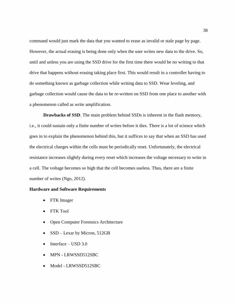
Hardware and Software Requirements
• FTK Imager
• FTK Tool
• Open Computer Forensics Architecture
• SSD – Lexar by Micron, 512GB
• Interface – USD 3.0
• MPN - LRWSSD512SBC
• Model - LRWSSD512SBC
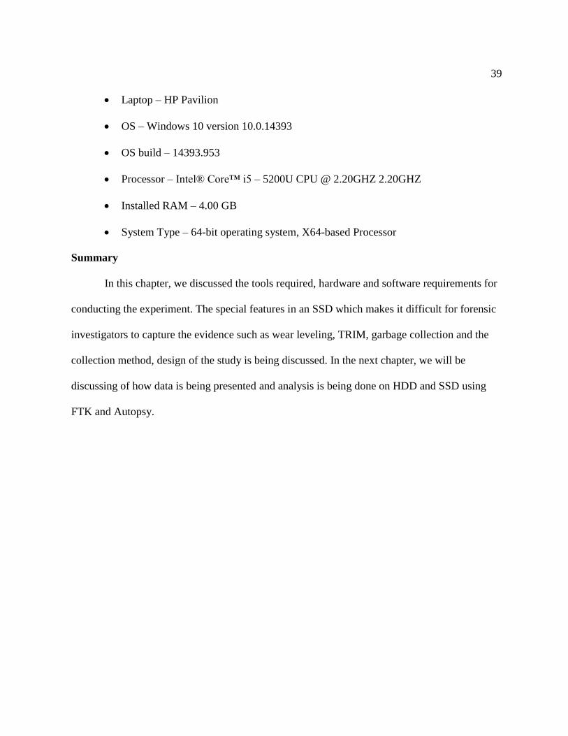
39
• Laptop – HP Pavilion
• OS – Windows 10 version 10.0.14393
• OS build – 14393.953
• Processor – Intel® Core™ i5 – 5200U CPU @ 2.20GHZ 2.20GHZ
• Installed RAM – 4.00 GB
• System Type – 64-bit operating system, X64-based Processor
Summary
In this chapter, we discussed the tools required, hardware and software requirements for
conducting the experiment. The special features in an SSD which makes it difficult for forensic
investigators to capture the evidence such as wear leveling, TRIM, garbage collection and the
collection method, design of the study is being discussed. In the next chapter, we will be
discussing of how data is being presented and analysis is being done on HDD and SSD using
FTK and Autopsy.

40
Chapter IV: Data Presentation and Analysis
Introduction
In this chapter, we will prepare an evidence file by collecting data and key words to
search them, we will discuss how this data is being collected and stored in evidence folders,
total number of original files that we pass to SSD and HDD. We will also discuss how data is
being stored in both devices, how the images of evidence files passed to the drives are created.
We will discuss how FTK and Autopsy are being used for creating the image files from the
drives, how HD Shredder is used to format the drives and analyze the evidence folder when it is
passed through FTK Toolkit and Autopsy.
Data Presentation
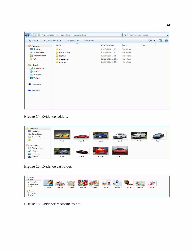
The evidence is collected in the form of junk data which is the combination of word
documents, excel documents, notes, images and actual evidence. Actual evidences that we are
investigating on includes cars, farmhouses, phones, medicines and laptops. Evidences are
passed with different combinations into each drive multiple times and deleted before creating
image files.
41
Figure 14: Evidence folders.
Figure 15: Evidence car folder.
Figure 16: Evidence medicine folder.

42
Figure 17: Evidence farm house folder.
Figure 18: Evidence phone folder.
Figure 19: Evidence laptop folder.
Evidence files are now passes to both the drives by deleting them multiple times with
various combinations to get number of hits for each key word search in FTK and Autopsy, these
evidences files were created and a Junk File folder which has multiple Word Documents, Excel
Sheets, PDF Files, and Images is passed along with the actual evidences. The sample project
folder that we are investigating contains around 80 GB of data

43
Figure 20: Combined file size of the evidence, evidence thrashers, and junk file.
Both SSD and HDD are wiped using HD Shredder. This will wipe all the data from the
drives.

44
Figure 21: Installation of HD shredder.
Figure 22: Running HD shredder.
45
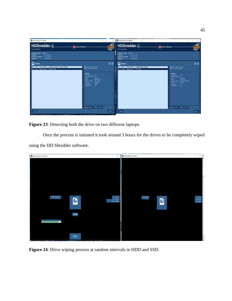
Figure 23: Detecting both the drive on two different laptops.
Once the process is initiated it took around 3 hours for the drives to be completely wiped
using the HD Shredder software.
Figure 24: Drive wiping process at random intervals in HDD and SSD.

46
Figure 25: Successful completion of disk wiping using HD shredder.
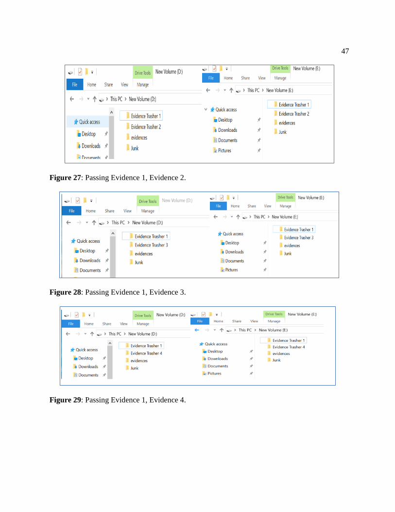
All the evidence thrasher files are passed to both HDD and SSD at different
combinations. The following figure illustrates the different combinations that are being used.
Figure 26: Passing evidence.
47
Figure 27: Passing Evidence 1, Evidence 2.
Figure 28: Passing Evidence 1, Evidence 3.
Figure 29: Passing Evidence 1, Evidence 4.
48
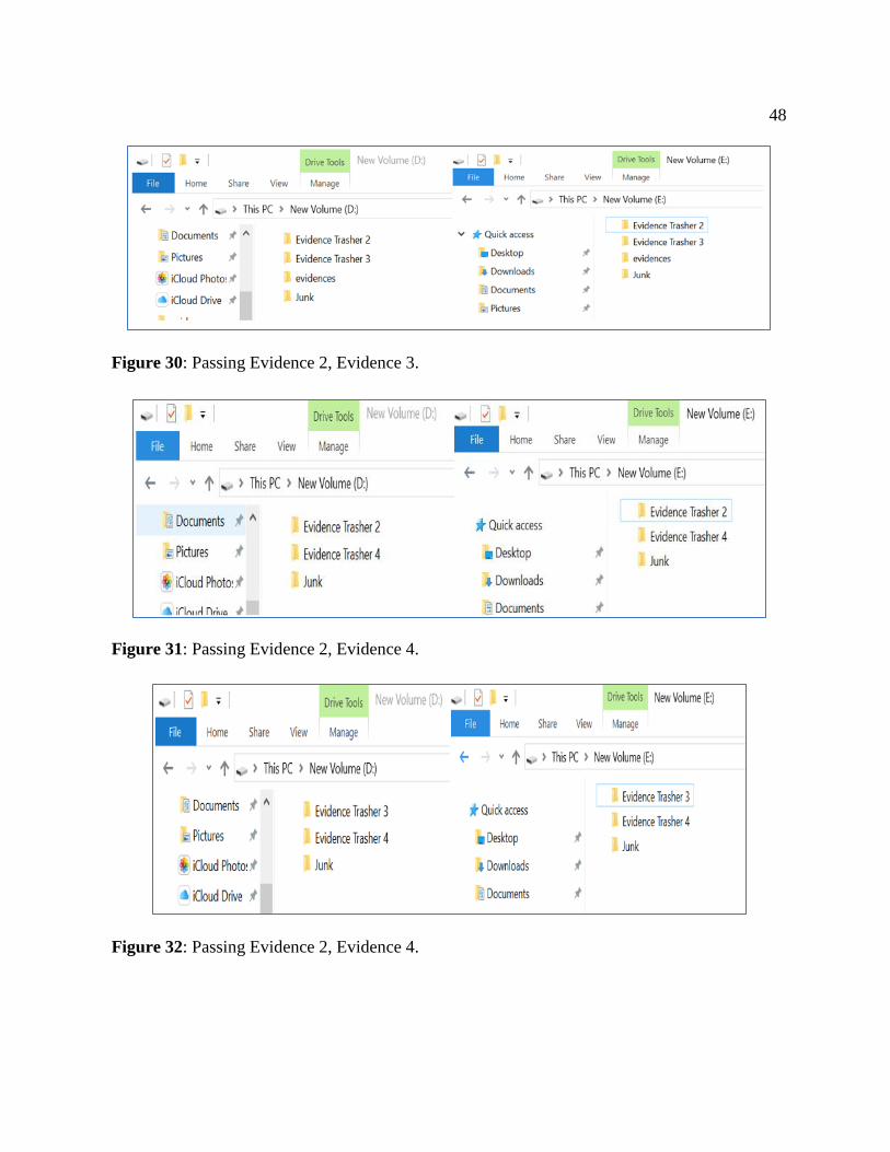
Figure 30: Passing Evidence 2, Evidence 3.
Figure 31: Passing Evidence 2, Evidence 4.
Figure 32: Passing Evidence 2, Evidence 4.
49
After the completion of all these combinations, the process is being repeated eight times
by changing the order of combinations and disks are being formatted each time combinations
are done.
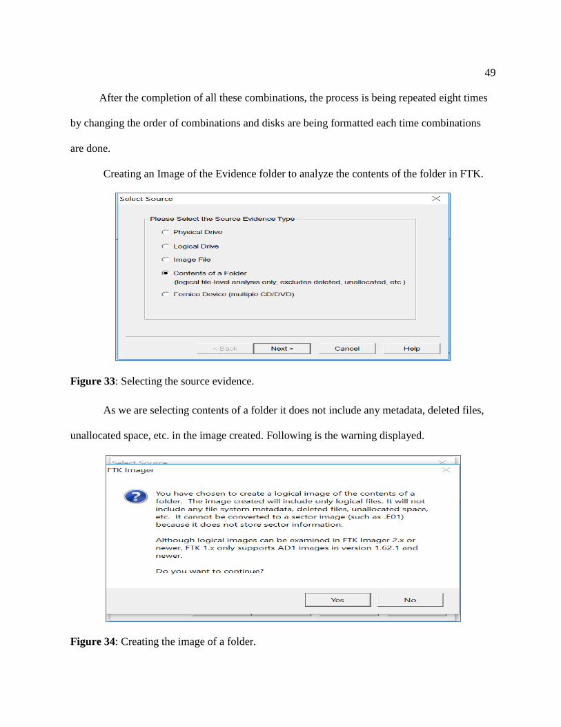
Creating an Image of the Evidence folder to analyze the contents of the folder in FTK.
Figure 33: Selecting the source evidence.
As we are selecting contents of a folder it does not include any metadata, deleted files,
unallocated space, etc. in the image created. Following is the warning displayed.
Figure 34: Creating the image of a folder.
50
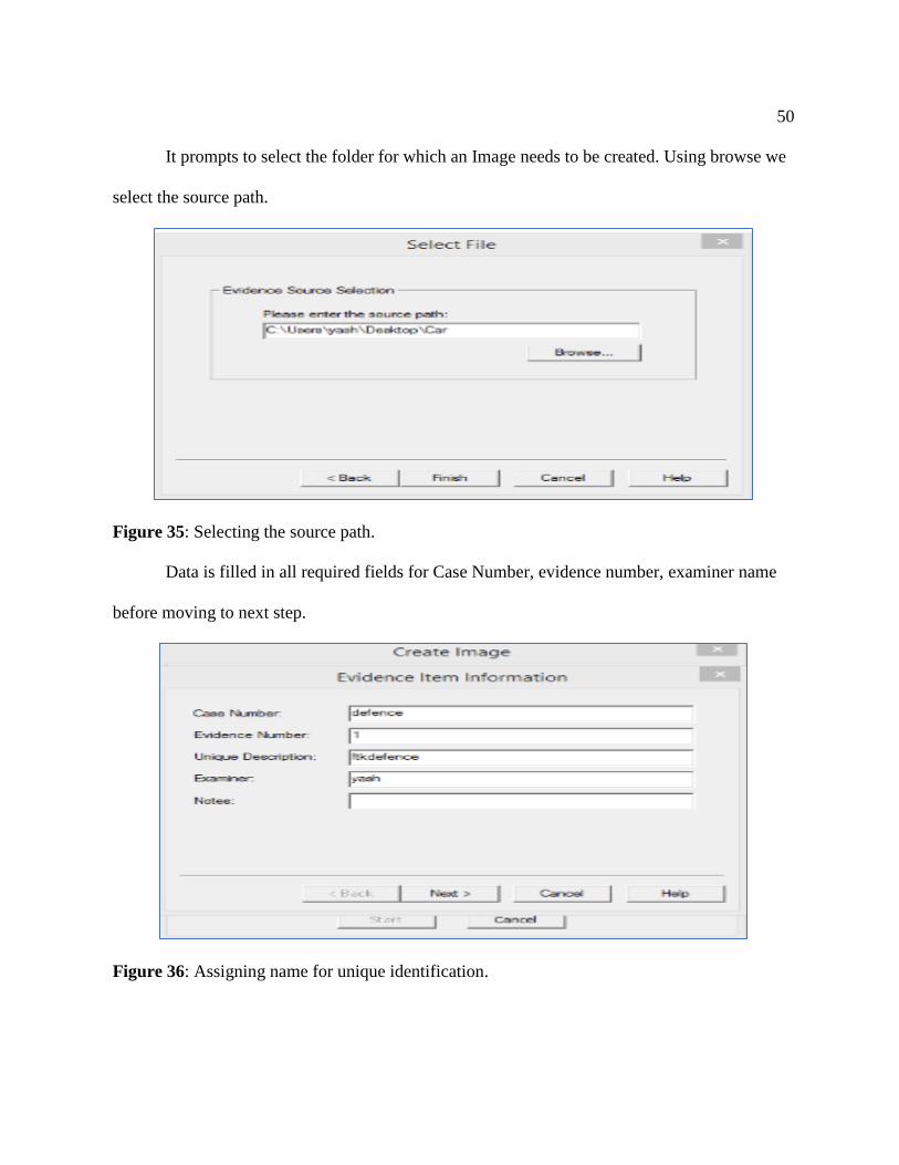
It prompts to select the folder for which an Image needs to be created. Using browse we
select the source path.
Figure 35: Selecting the source path.
Data is filled in all required fields for Case Number, evidence number, examiner name
before moving to next step.
Figure 36: Assigning name for unique identification.

51
The image source is selected from the drive and image file destination is selected for
storing them
Figure 37: Assigning image destination.
Fragmentation size is given to create multiple images of the evidence file and then click
on finish to start creating image files
Figure 38: Selecting the fragmentation size.

52
The image creation can be seen in the below image as the image files for the selected
folder or evidence.
Figure 39: Processing of image creation.
Once the image for the evidence folder is created the below data is displayed which
ensures successful creation. Hash number is created for the image file to make sure no
evidences are tampered in future
Figure 40: Verifying results of the image created.

53
All the details that we provided are shown in this image this is summary of the image
file
Figure 41: Image summary for image.
On successful creation of the image the files are stored in the location we specified. We
have chosen desktop as primary location during image creation, so all the image files created in
the process are stored on to desktop.
Figure 42: Image of evidence folder.

54
Data Analysis
After the creation of image files of evidences, the images are analyzed to retrieve results.
The image files are analyzed using two forensic tools FTK Toolkit and Autopsy.
Analyzing the image of evidence folder using FTK. To analyze the image created
using the FTK Imager, we will use FTK toolkit. We need to provide the required fields before
starting analysis. Case Number, examiner name, path of the image file and case folder is
provided.
In the next step, we need to enter personal details of the investigator who is analyzing
the image like: Which company, Name of the investigator, Address, phone number, and Email
address. Click on next to proceed further.
Figure 43: Filling personal details of investigator (Marupudi, 2017).
In the next step, we now need to select the image file that need to be analyzed. As we are
analyzing an entire drive we need to select Acquired Image of the Drive radio button and click
on continue.

55
Figure 44: Adding image file to FTK toolkit.
Image file from the system is selected using the browse option and click on OK.
Figure 45: Adding image file to analyze (Marupudi, 2017).
In the next step, the details of the image file selected is displayed with next button and
add evidence button.

56
Figure 46: Evidence summary and add evidence (Marupudi, 2017).
Image is being processed.
Figure 47: Extracting the files from image (Marupudi, 2017).
After the image file is processed it is analyzes using the FTK toolkit. Home page will
look like below.

57
Figure 48: Home page of FTK toolkit (Marupudi, 2017).
In the evidence folder we created, we used 5 different keywords such as car, medicines,
laptops, farmhouse, and phones.
FTK has a feature to look at the image files which we passed. From the evidence folder,
we are aware that there is a picture of a farm house. Searching with a specific name is also
possible in FTK.
Figure 49: Searching by the file names.
Analyzing the image of evidence folder using autopsy. The image file we created for
the FTK is not compatible with Autopsy. Autopsy uses the E01 format where as FTK used Ad
format.
To convert format, we use Forensic Imager tool. This involve following steps.

58
Figure 50: Home page of forensic imager.
We select second option to convert one format to another. Select option two and fill in
the required details.
Figure 51: Selecting image to convert.
59
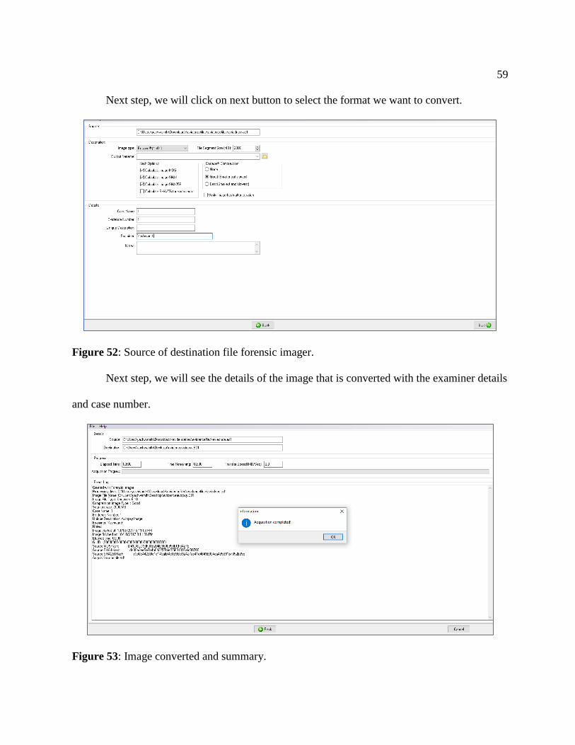
Next step, we will click on next button to select the format we want to convert.
Figure 52: Source of destination file forensic imager.
Next step, we will see the details of the image that is converted with the examiner details
and case number.
Figure 53: Image converted and summary.

60
Summary
In this chapter, we have created the evidences for our investigation which can be done
by creating an image file and analyzed using two different tools FTK toolkit and. We will create
image files for the evidences passed into the Hard Drive Disk and Solid-State Drive in the next
chapter. We use HD shredder for formatting the drives before getting them ready for the
investigation.

61
Chapter V: Introduction, Results and Conclusion
Introduction
In this chapter, we will go through the images creation of both HDD and SSD using
FTK imager and converting them to E01 format using Forensic Imager for Analyzing the results
in Autopsy. We will compare number of hits with the original files we passed and comparing
the results of SSD with HDD. We will graphically analyze hits obtained during keyword
searches in both tools.
Results
Creating image of HDD. While creating the Image of an HDD we use logical drive
option instead of Physical drive as we are creating image of a specific drive that is externally
connected to the system. We are suing an external device connected to investigation laptop.
Figure 54: HDD connected to Laptop 1.

62
Figure 55: Home screen of FTK.
Figure 56: Selecting option from type of device.
The hard Drive that we connected to laptop is shown as D drive, so we are selecting the
option D drive from the list as shown in the figure below.

63
Figure 57: Selecting HDD drive for image creation.
Evidence Item information is given in next step by giving Case Number, Examiner
name.
Figure 58: Create image evidence item information.
64
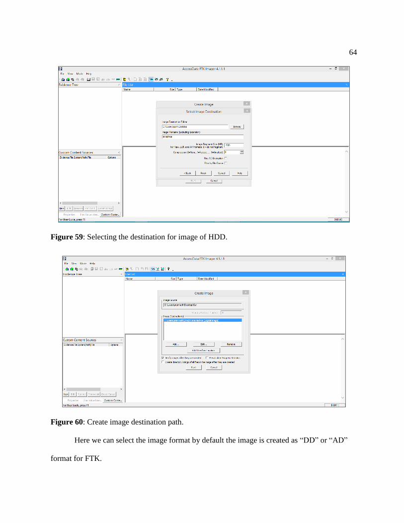
Figure 59: Selecting the destination for image of HDD.
Figure 60: Create image destination path.
Here we can select the image format by default the image is created as “DD” or “AD”
format for FTK.

65
Figure 61: Selecting the type of image format.
Figure 62: Unique identification for the image file.
The image size would be more or equal to the size of the drive. To fit the image into the
device we fragment it into parts for easy analysis. We select fragmentation size from the below
step. Here we are selecting 102400 MD size.

66
Figure 63: Selecting the fragmentation size for image of HDD (Marupudi, 2017).
The drive we are using to create image is 1TB external hard drive, so the image file may
be equal to the size or of larger size, so we keep track of the time. Pre-Calculate progress is
checked before starting the process.
Figure 64: Verifying and starting the process of image creation of HDD.
Random pictures were captured during different stages of the image creation of the
HDD drive.
67
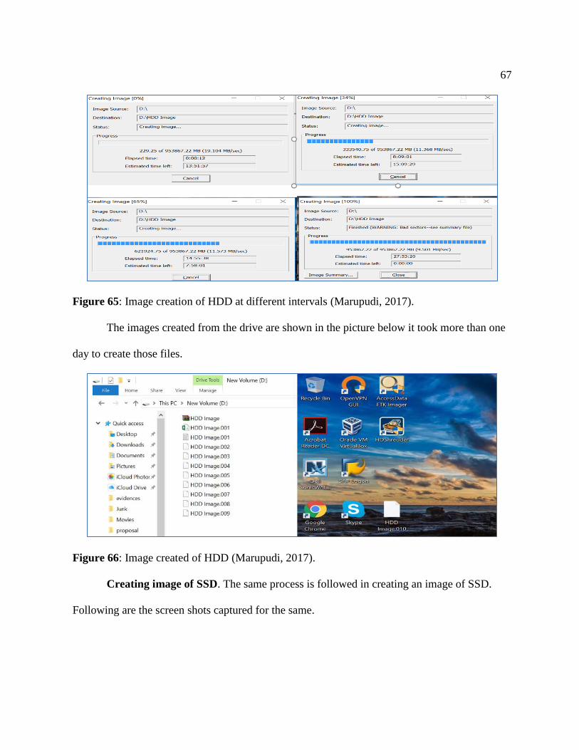
Figure 65: Image creation of HDD at different intervals (Marupudi, 2017).
The images created from the drive are shown in the picture below it took more than one
day to create those files.
Figure 66: Image created of HDD (Marupudi, 2017).
Creating image of SSD. The same process is followed in creating an image of SSD.
Following are the screen shots captured for the same.

68
Figure 67: SSD connected to second laptop (Marupudi, 2017).
Figure 68: Selecting the logical drive for SSD image creation.
Figure 69: Selecting SSD drive for image creation.

69
Figure 70: Selecting the destination for image of SSD.
Figure 71: Selecting the type of SSD image.
Figure 72: Selecting the fragmentation size for image of SSD.

70
Figure 73: Verifying and starting the process of image creation of SSD.
Figure 74: Image creation of SSD at different intervals (Marupudi, 2017).

71
Figure 75: Images created of SSD (Marupudi, 2017).
Analyzing image of HDD in FTK. After the image files are created for the HDD, the
images are now analyzed using the FTK toolkit. The below image is the home page of the FTK
after the image file is passed.
Figure 76: Processing image 1 of HDD.
The keyword searches are done on the images processed to get the number of hits
obtained, below shows the hits of car.

72
Figure 77: Files identified by searching keywords in image 1 of HDD.
We will analyze the results by identifying the number of files and number of hits by
individual keyword. Following is the results identified in Image 1 of HDD.
Figure 78: Results identified in image 1 of HDD.
The same process is repeated for all other images that were created earlier which are as
shown below.
Figure 79: Processing image 2 of HDD.

73
Figure 80: Results identified in image 2 of HDD.
Figure 81: Files identified by searching keywords in image 2 of HDD.
Ten image files obtained are analyzed by searching for the keywords in each image. The
cumulative results of the hits obtained in HDD are shown below in the table.

74
Table 1
Results Obtained from Images of HDD in FTK
Keyword Files in HDD Hits in HDD
Car 1099 5731
Medicine 460 688
Phone 462 3208
Farm House 467 7272
Laptop 463 1201
Analyzing image of SSD in FTK. The same process of Image creation and analyzing
the images using FTK Toolkit is followed for SSD. Following are the steps followed.
Figure 82: Adding evidence to analyze results of SSD (Marupudi, 2017).
Figure 83: Processing image 1 of SSD (Marupudi, 2017).

75
Figure 84: Processing image 2 of SSD (Marupudi, 2017).
Figure 85: Processing image 3 of SSD (Marupudi, 2017).
76
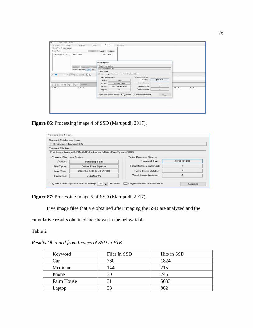
Figure 86: Processing image 4 of SSD (Marupudi, 2017).
Figure 87: Processing image 5 of SSD (Marupudi, 2017).
Five image files that are obtained after imaging the SSD are analyzed and the
cumulative results obtained are shown in the below table.
Table 2
Results Obtained from Images of SSD in FTK
Keyword Files in SSD Hits in SSD
Car 760 1824
Medicine 144 215
Phone 30 245
Farm House 31 5633
Laptop 28 882

77
We have the different results which were found by the key word searches in SSD, HDD
and the original files and hits that were to be identified in both the drives. To make the
comparison to be clear we will be using a tabular format as well as a pivot chart representation
of all the results obtained. The following table compares the original number of files, hits with
those identified in both HDD and SSD.
Table 3
Comparing the Results Obtained in FTK
Keyword
Original
Files
Files in
HDD
Files
in
SSD
Original
Hits
Hits in
HDD
Hits
in
SSD
Car 1964 1099 760 9181 5732 1824
Medicine 764 460 144 1045 688 215
Phone 555 462 30 5532 3209 245
Farm
House 692 467 31 14954 7202 5633
Laptop 1161 463 28 3588 1201 882
Graphical representation of Hits in FTK.
Figure 88: Difference in results identified by number of files in FTK.
0
500
1000
1500
2000
2500
Car Medicine Phone Farm House Laptop
Hits in FTK against Original Files
Original Files Files in HDD Files in SSD

78
Figure 89: Difference in results identified by number of Hit in FTK.
Analyzing Image of HDD in Autopsy. The image files that are converted using the
Forensic Imager is now analyzed using autopsy tool. The Image files which are in E01 format
are now passed into a new case created in Autopsy using following steps and then a keyword
search is done to analyze the number of hits in both the images created for HDD and SSD.
First step involves creating a case and a database to analyze the case.
Figure 90: New case information.
9181
1045
5532
14954
3588
6576
6453109
7348
13891678215 245
5788
864
0
5000
10000
15000
20000
Car Medicine Phone Farm House Laptop
Hits in FTK against Original Hits
Original Hits Hits in HDD Hits in SSD

79
Next step, we give required details for creating a case folder in local system by
specifying base directory and case Name. We can also specify if the case is for a single user or a
multiple user using the options.
Figure 91: Set case number and examiner.
Next step, we provide details of the case number and the examiner details and click on
finish button to start creating a case folder and database.
Figure 92: Creating a case database.
80
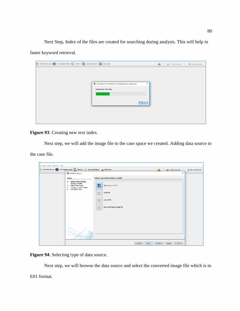
Next Step, Index of the files are created for searching during analysis. This will help in
faster keyword retrieval.
Figure 93: Creating new text index.
Next step, we will add the image file to the case space we created. Adding data source to
the case file.
Figure 94: Selecting type of data source.
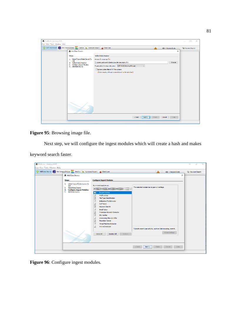
Next step, we will browse the data source and select the converted image file which is in
E01 format.
81
Figure 95: Browsing image file.
Next step, we will configure the ingest modules which will create a hash and makes
keyword search faster.
Figure 96: Configure ingest modules.

82
The keyword search is made using the five keywords and the below results are obtained
from the hits in both SSD and HDD.
Table 4
Results Obtained from Images of HDD in Autopsy
Keyword Files in HDD Hits in HDD
Car 1167 6576
Medicine 479 645
Phone 454 3109
Farm House 475 7348
Laptop 498 1389
Analyzing Image of SDD in Autopsy.
Table 5
Results Obtained from Images of SSD in Autopsy
Keyword Files in SSD Hits in SSD
Car 765 1678
Medicine 144 215
Phone 32 245
Farm House 35 5788
Laptop 31 864
Table 6
Comparing the Results Obtained in Autopsy
Keyword
Original
Files
Files
in
HDD
Files
in
SSD
Original
Hits
Hits
in
HDD
Hits
in
SSD
Car 1964 1167 765 9181 6576 1678
Medicine 764 479 144 1045 645 215
Phone 555 454 32 5532 3109 245
Farm House 692 475 35 14954 7348 5788
Laptop 1161 498 31 3588 1389 864

83
Graphical representation of hits in Autopsy. Visualizing number of files obtained
from HDD and SSD in Autopsy through Chart.
Figure 97: Difference in results identified by number of files in autopsy.
Visualizing number of files obtained from HDD and SSD with original files passed in
Autopsy through Chart.
Figure 98: Difference in results identified by number of Hit in autopsy.
0
500
1000
1500
2000
2500
Car Medicine Phone Farm House Laptop
Hits in Autopsy against Original Files
Original Files Files in HDD Files in SSD
0
2000
4000
6000
8000
10000
12000
14000
16000
Car Medicine Phone Farm House Laptop
Hits in Autopsy against Original Hits
Original Hits Hits in HDD Hits in SSD

84
Conclusion
Same Evidence file is created for both the storage devices SSD and HDD which are
formatted using the HD Shredder to wipe out data completely, passed with different
combinations of data that has been taken as an evidence which are being transferred. FTK
Imager is used to create the image files of the drives (SSD and HDD) to analyze then using an
investigator's laptop which has FTK Toolkit and Autopsy tool in it. However, due to the
functionality of the devices and other factors that we discussed in the paper it is evident that the
results of the evidences are different in both drives.
In this paper, we have discussed about the features of Solid State Drives, their
advantages and mechanism of storage as well as other important features. Based on the study
we conducted, and the results obtained from the experiment using FTK and Autopsy it is proven
that SSD’s has a phenomenon to destroy or loss critical evidences which may create trouble for
the forensic investigators with the existing tools for finding key evidence and resolving cases
that were solved by using traditional methods on HDD.

85
References
Aaronson, L. (2008). How it works: The sturdiest solid-state storage. Retrieved April 15, 2017,
from http://www.popsci.com/node/19967.
AccessData. (2017). AccessData. Retrieved from http://accessdata.com:
http://accessdata.com/solutions/digital-forensics/forensic-toolkit-ftk.
Amazon.ca. (2017). Solid state drives. Retrieved from https://www.amazon.com/Samsung-2-5-
Inch-Internal-MZ-75E4T0B-AM/dp/B01G844OOO.
Amazon.ca (2017). Internal structure. Retrieved from https://www.amazon.com/Samsung-
500GB-mSATA3-Solid-Retail/dp/B00HWHVOQS.
Azemovic, J. (2010, August 27). SQL Server Pro. Retrieved from http://sqlmag.com/sql-
server/csi-sql-server.
Chen, F., Koufaty, D., & Zhang, X. (2016). Hystor: Making the best use of solid state drives in
high performance storage systems. In Conference Proceedings of the 25th International
Conference on Supercomputing, Tucson, AZ, May 31-June 4.
Computer Hope. (2017a). Advantages of SSD over HDD. Retrieved from http://www.
computerhope.com: http://www.computerhope.com/issues/ch001396.htm.
Computer Hope. (2017b, October 17). HardDrive. Retrieved from https://www.
computerhope.com/jargon/h/harddriv.htm.
Dennon, A. (2016, January 29). The digital forensics process. Retrieved from PICPA:
https://www.picpa.org/articles/cpa-now-blog/cpa-now/2016/01/29/the-digital-forensics-
process.
86
Edwards, B. (2012, January 17). http://www.pcworld.com. Retrieved from pcworld:
http://www.pcworld.com/article/246617/storage/evolution-of-the-solid-state-drive.html.
Encase. (2017). Software guidence. Retrieved from www.guidancesoftware.com:
https://www.guidancesoftware.com/encase-forensic.
ESSD Embedded. (2017). Embedded SSD. Retrieved from https://product.tdk.com/info/en/
techlibrary/archives/techjournal/vol15_essd/contents03.html.
Evan Amos. (2017, October). Wikipedia. Retrieved from https://en.wikipedia.org/wiki/
Hard_disk_drive#/media/File:Laptop-hard-drive-exposed.jpg.
Evans, C. (2012, August). Flash! All-solid-state arrays. Retrieved April 15, 2017, from
http://searchstorage.techtarget.com/ magazineContent/Flash-All-solid-state-arrays.
Fisher, T. (2017, September 12). LifeWire. Retrieved from https://www.lifewire.com/what-is-a-
hard-disk-drive-2618152.
Garfinkel, S. L. (2013, October). Modern crime often leaves an electronic trail. Finding and
preserving that evidence requires careful methods as well as technical skill. Retrieved
from http://www.americanscientist.org: http://www.americanscientist.org/issues/
pub/digital-forensics.
Harris, W. (2015). How stuff works. Retrieved from http://computer.howstuffworks.com:
http://computer.howstuffworks.com/solid-state-drive.htm.
Humphries, M. (2017). Geek. Retrieved from http://www.geek.com: http://www.geek.com/
chips/toshiba-hard-drives-will-be-40tb-by-2020-ssds-will-be-128tb-by-2018-1632425/.

87
Hutchinson, L. (2012). Solid-state revolution: In-depth on how SSDs really work. Retrieved
April 15, 2017, from http://arstechnica.com/information-technology/2012/06/inside-the-
ssd-revolution-how-solid-state-disks-really-work/.
Janorkar, P. (2015, August 19). Seminar topics.
Kerekes, Z. (2017). Storagesearch. Retrieved from http://www.storagesearch.com:
http://www.storagesearch.com/chartingtheriseofssds.html.
LifeWire. (2017, September). LifeWire. Retrieved from https://www.lifewire.com/how-to-wipe-
a-hard-drive-2624527.
Marupudi, S. S. (2017). Solid state drives: New challenge for forensic investigation. Solid State
Drives: New Challenge for Forensic Investigation.
Masuoka, F. (1987). New ultra high density EPROM and flash EEPROM with NAND structure
cell. IEEE, Electron Devices Meeting, 1987 International. IEEE. Retrieved 04-15-2017.
Mellor, C. (2013, May 9). The register. Retrieved from https://www.theregister.co.uk/2013/
05/09/ihs_on_pc_hdd_ssd_units/.
Mizota, K. (2015, 01 07). Encase-forensic. Retrieved from http://encase-forensic-
blog.guidancesoftware.com/search/label/Decryption.
Newegg. (2017). Newegg. Retrieved from https://www.newegg.com/Product/Product.
aspx?Item=N82E16820147467.
Ngo, D. (2012, August 22). Storage talk: Why you should get an SSD and keep your HDD, too.
Retrieved April 15, 2017, from https://www.cnet.com/news/storage-talk-why-you-
should-get-an-ssd-and-keep-your-hdd-too/.

88
Ngo., D. (2013, March 1). Digital storage basics, Part 4: SSD explained. Retrieved April 15,
2017, from CNet: https://www.cnet.com/how-to/digital-storage-basics-part-4-ssd-
explained/.
Rouse, M. (2016, May). Searchsolidstatestoragetechtarget. Retrieved from TechTarget:
http://searchsolidstatestorage.techtarget.com/definition/SSD-solid-state-drive.
S.A.S., A. (2017). DFF homepage. Retrieved from digital-forensic: http://www.digital-
forensic.org/.
Seagate. (2012, August 22). The top 20 things to know about SSD. Retrieved April 15, 2017,
from Seagate: http://www.seagate.com/files/docs/pdf/ssd-faq-us.pdf.
Shankdhar, P. (2017). InfosecInstitute. Retrieved from http://resources.infosecinstitute.com:
http://resources.infosecinstitute.com/computer-forensics-tools/#gref.
Tools, K. (2014, May 16). Kali tools.
wiki. (2017). Wikipedia. Retrieved from https://en.wikipedia.org/wiki/Forensic_Toolkit.
X-Ways. (2017). Forensics. Retrieved from www.x-ways.net: http://www.x-
ways.net/forensics/.
X-ways. (2017). X-ways. Retrieved from http://www.x-ways.net/pics/xwf_screen_eng.png.