differential air-pressure transmitter - rockwell...
TRANSCRIPT
Installation Instructions
Differential Air-pressure TransmitterCatalog Numbers 1414-IPZ10FODAA, 1414-IPZ10FNDAA, 1414-IPD10FNRAA, 1414-CPZ10FODAA, 1414-CPZ10FNDAA, 1414-CPD10PNRAA
Before InstallationRead these installation instructions carefully before commissioning the pressure transmitter.
Topic Page
Before Installation 1
Important User Information 2
About the Differential Air-pressure Transmitter 3
Differential Air-pressure Transmitter Installation 4
Power-up Instruction 7
Specifications 9
Dimensions 10
ATTENTION: • Failure to follow these instructions may result in product damage. This device must be
installed by a qualified technician.• Use electrostatic discharge precautions during installation and do not exceed the device
ratings.
WARNING: Do not use in an explosive or hazardous environment, with combustible or flammable gasses, as safety or emergency stop devices or in any other application where failure of the product could result in personal injury.
2 Differential Air-pressure Transmitter
Important User Information
Solid-state equipment has operational characteristics differing from those of electromechanical equipment. Safety Guidelines for the Application, Installation and Maintenance of Solid State Controls (Publication SGI-1.1 available from your local Rockwell Automation sales office or online at http://www.rockwellautomation.com/literature/) describes some important differences between solid-state equipment and hard-wired electromechanical devices. Because of this difference, and also because of the wide variety of uses for solid-state equipment, all persons responsible for applying this equipment must satisfy themselves that each intended application of this equipment is acceptable.
In no event will Rockwell Automation, Inc. be responsible or liable for indirect or consequential damages resulting from the use or application of this equipment.
The examples and diagrams in this manual are included solely for illustrative purposes. Because of the many variables and requirements associated with any particular installation, Rockwell Automation, Inc. cannot assume responsibility or liability for actual use based on the examples and diagrams.
No patent liability is assumed by Rockwell Automation, Inc. with respect to use of information, circuits, equipment, or software described in this manual.
Reproduction of the contents of this manual, in whole or in part, without written permission of Rockwell Automation, Inc., is prohibited.
Throughout this manual, when necessary, we use notes to make you aware of safety considerations.
WARNING: Identifies information about practices or circumstances that can cause an explosion in a hazardous environment, which may lead to personal injury or death, property damage, or economic loss.
ATTENTION: Identifies information about practices or circumstances that can lead to personal injury or death, property damage, or economic loss. Attentions help you identify a hazard, avoid a hazard and recognize the consequences.
SHOCK HAZARD: Labels may be on or inside the equipment, for example, drive or motor, to alert people that dangerous voltage may be present.
BURN HAZARD: Labels may be on or inside the equipment, for example, drive or motor, to alert people that surfaces may reach dangerous temperatures.
IMPORTANT Identifies information that is critical for successful application and understanding of the product.
Publication 1414-IN011B-EN-P - July 2010
Differential Air-pressure Transmitter 3
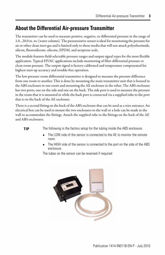
About the Differential Air-pressure TransmitterThe transmitter can be used to measure positive, negative, or differential pressure in the range of 1.0…20.0 in. wc (water column). The piezoresistive sensor is ideal for monitoring the pressure for air or other clean inert gas and is limited only to those media that will not attack polyetherimide, silicon, fluorosilicone, silicone, EPDM, and neoprene seals.
The module features field-selectable pressure ranges and output signal types for the most flexible application. Typical HVAC applications include monitoring of filter differential pressure or clean room pressure. The output signal is factory calibrated and temperature compensated for highest start-up accuracy and trouble-free operation.
The low-pressure room differential transmitter is designed to measure the pressure difference from one room to another. This is done by mounting the main transmitter unit that is housed in the ABS enclosure in one room and mounting the AE enclosure in the other. The ABS enclosure has two ports, one on the side and one on the back. The side port is used to measure the pressure in the room that it is mounted in while the back port is connected via a supplied tube to the port that is on the back of the AE enclosure.
There is a second fitting on the back of the ABS enclosure that can be used as a wire entrance. An electrical box can be used to mount the two enclosures to the wall or a hole can be made in the wall to accommodate the fittings. Attach the supplied tube to the fittings on the back of the AE and ABS enclosures.
TIP The following is the factory setup for the tubing inside the ABS enclosure.
• The LOW side of the sensor is connected to the AE to monitor the remote room.
• The HIGH side of the sensor is connected to the port on the side of the ABS enclosure.
The tubes on the sensor can be reversed if required
Publication 1414-IN011B-EN-P - July 2010
4 Differential Air-pressure Transmitter
Differential Air-pressure Transmitter InstallationThe transmitter mounts on any surface using the two holes provided on the base of the unit. Make sure there is enough space around the unit to connect the pressure tubing without kinking and avoid locations where severe vibrations or excessive moisture are present. Mount the enclosure with two user-supplied screws but do not over-tighten.
The unit may be mounted in any position but is typically installed on a vertical surface with the pressure ports on the right and the cable entrance on the left. The enclosure has a standard ½ in. conduit opening and may be installed with either conduit and a conduit coupler or a cable gland type fitting.
Room Pressure Monitor - Mount the ABS box in the room where the pressure display is desired. Mount the AE enclosure in the second room and connect the two using the supplied hose or equivalent. Note that the unit is factory set with the LOW port in the ABS enclosure and the HIGH port in the AE enclosure. To change this, reverse the hose connections on the board in the ABS enclosure.
Differential Air-pressure Transmitter Wiring and ConnectionThe transmitter has standard screw-block connectors and easy wire access to facilitate wiring. We recommend that shielded twisted-pair wiring at least 22 AWG be used for all connections and that the device wires not be run in the same conduit with wiring used to supply inductive loads such as motors.
Make all connections in accordance with national and local electrical codes.
The device power (12…28V AC or 15…35V DC measured at the transmitter) is connected to the terminal marked PWR. This terminal is used for the positive DC voltage or the hot side of the AC voltage. The device is reverse voltage protected and as such will not operate if connected backwards.
For voltage output signal types (three-wire) or for AC power supply operation (three-wire), the common of the power supply is connected to the terminal marked COM. Note that this device has a half-wave type power supply which means the power supply common is the same as the output signal common. Therefore, several devices may be connected to one power supply and the output signals all share the same signal common. Use caution when grounding the secondary of an AC transformer or when wiring multiple devices to ensure that the circuit ground point is the same on all devices and the controller. This terminal is not used for loop-powered 4…20 mA output type (2-wire).
ATTENTION: Disconnect the power supply before making any connections to prevent electrical shock or equipment damage.
Publication 1414-IN011B-EN-P - July 2010
Differential Air-pressure Transmitter 5
The analog output signal is available on the OUT terminal. This signal is jumper selectable for either a voltage output or a standard loop-powered 4…20 mA output signal type. When voltage mode is selected, either 0…5V DC or 0…10V DC can also be selected. These options are indicated on the device circuit board. The analog output signal is typically connected directly to the Building Automation System (B.A.S.) and used as a control parameter or for logging purposes.
For voltage type output signal the device has a minimum load that it is able to drive, similarly for current type output signal the device has a maximum load that it is able to drive with a particular power supply voltage. Observe and follow these ratings in the Specification section or inaccurate reading may result.
The 4…20 mA output signal can easily be converted to a 1…5V DC signal for controllers accepting this type of input. Simply insert a 250 Ω (0.1% is best) resistor between the ‘+’ and ‘-’ inputs of the controller. This will convert the 4…20 mA signal to the desired 1…5V DC.
Pneumatic ConnectionsThe two pressure ports on the end of the enclosure are labeled High and Low. The output signal reads a positive value when the port pressure is higher on the High port than the Low port so ensure these ports are connected correctly.
Use 0.170 in. I.D. flexible tubing for the High and Low pressure connections. Arrange the tubing to minimize stress on the connections and ensure there are no kinks in the tubing. For most accurate measurements, do not leave the Low port open to the atmosphere, run a return line from the Low port to the vicinity of the point being measured.
Ensure the tubing to be used is clean and do not allow material to fall into the pressure ports as contamination could damage the sensor.
When removing tubing use care to avoid breaking the ports. In some cases it is better to cut the tubing off rather than pulling it off but be careful not to cut the fitting or an air leak may occur.
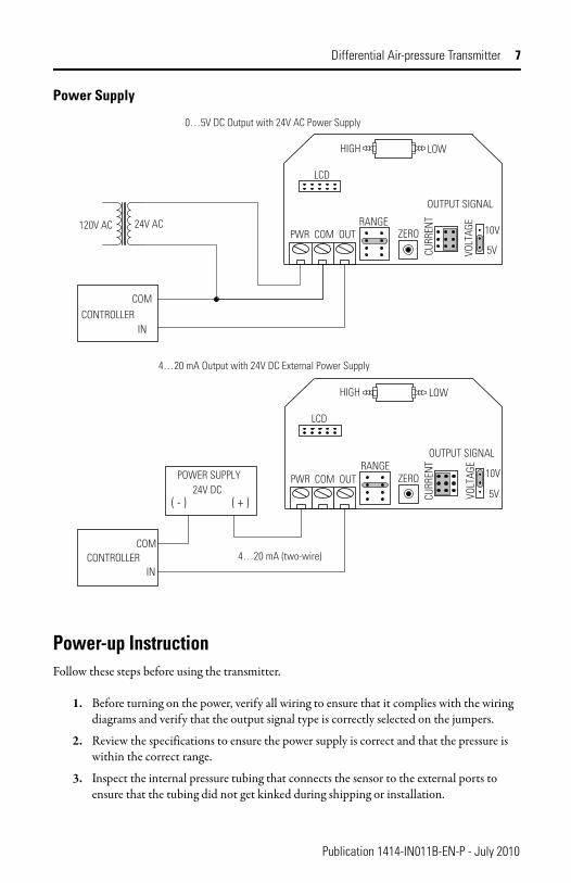
Differential Air-pressure Transmitter ConfigurationThe transmitter is configured with push-on type jumpers on the circuit board as shown on the Power Supply drawing. These jumpers are used to select the output signal type and the input pressure range.
The module is factory configured to operate in the 4…20 mA output mode. You can change the voltage mode by moving the three jumpers from the positions marked Current to the positions marked Voltage. Before moving these jumpers, study the current jumper position and then move the jumpers to the new position. If these jumpers are rotated 90 degrees and installed incorrectly the product will not work and device damage may occur.
Once the output mode is changed to voltage, the output scale may be changed to either 0…5V DC or 0…10V DC. This is done by moving the single jumper to the 0…5V or 0…10V position.
Publication 1414-IN011B-EN-P - July 2010
6 Differential Air-pressure Transmitter
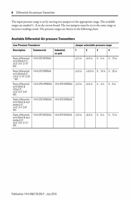
The input pressure range is set by moving two jumpers to the appropriate range. The available ranges are marked 1…8 on the circuit board. The two jumpers must be set to the same range or incorrect readings result. The pressure ranges are shown in the following chart:
Available Differential Air-pressure Transmitters
Low Pressure Transducer Jumper selectable pressure range
Description Commercial Industrial, cc-pcb
1 2 3 4
Room differential w/4-20mA±2.5”, ±5.0”,0-5”,0-10” WC
1414-CPZ10FVRAA ±2.5 in. ±5.0 in. 0…5 in. 0…10 in.
Room differential w/4-20mA±5.0”, ±10.0”,0-10”,0-20” WC
1414-CPZ10FRRAA ±5.0 in. ±10.0 in. 0…10 in. 0…20 in.
Room differential w/4-20mA & LCD±2.0”, ±4.0”,0-4”,0-8” WC
1414-CPD10PNRAA 1414-IPD10FNRAA ±2.0 in. ±4.0 in. 0…4 in. 0…8 in.
Static differential w/4-20mA & duct probe±2.0”, ±4.0”,0-4”,0-8” WC
1414-CPZ10FNDAA 1414-IPZ10FNDAA
Static differential w/4-20mA & duct probe±3.0”, ±6.0”,0-6”,0-12” WC
1414-CPZ10FODAA 1414-IPZ10FODAA ±3.0 in. ±6.0 in. 0…6 in. 0…12 in.
Publication 1414-IN011B-EN-P - July 2010
Differential Air-pressure Transmitter 7
Power Supply
Power-up InstructionFollow these steps before using the transmitter.
1. Before turning on the power, verify all wiring to ensure that it complies with the wiring diagrams and verify that the output signal type is correctly selected on the jumpers.
2. Review the specifications to ensure the power supply is correct and that the pressure is within the correct range.
3. Inspect the internal pressure tubing that connects the sensor to the external ports to ensure that the tubing did not get kinked during shipping or installation.
PWR COM OUTRANGE
ZERO
CURR
ENT
VOLT
AGE
OUTPUT SIGNAL
10V
5V
LCD
LOWHIGH
CONTROLLERIN
COM
24V AC120V AC
0…5V DC Output with 24V AC Power Supply
4…20 mA (two-wire)
PWR COM OUTRANGE
ZERO
CURR
ENT
VOLT
AGE
OUTPUT SIGNAL
10V
5V
LCD
LOWHIGH
POWER SUPPLY24V DC
( - ) ( + )
CONTROLLERIN
COM
4…20 mA Output with 24V DC External Power Supply
Publication 1414-IN011B-EN-P - July 2010
8 Differential Air-pressure Transmitter
4. Allow the transmitter to warm-up for several minutes before attempting to verify the device accuracy or adjust the null offset.
The module uses a sophisticated temperature compensation circuit to ensure maximum accuracy of the device. It is best to allow the transmitter to operate for one hour before any adjustment or calibration is performed.
5. Verify proper operation by measuring the output signal.
• For voltage output configuration, measure the voltage between the OUT and COM terminals. The voltmeter should read between 0…5V DC or 0…10V DC depending on the output range selected.
• For current output configuration, insert a mA meter in series with the OUT terminal. The mA meter should read between 4…20 mA.
OperationIf the module is set to a unipolar range such as 0…2 in. wc, then the pressure applied to the High port must be higher than the pressure applied to the Low port. In this case, if the Low port is left open to ambient pressure and the High port is used to measure a positive pressure, then the output pressure can be calculated as follows:
• 4…20 mA Pressure = [(Output current – 4 mA) / 16 mA] x Range
• 0…5V DC Pressure = (Output voltage / 5 V) x Range
• 0…10V DC Pressure = (Output voltage / 10 V) x Range
In the case of 0… 2 in. wc, 4 mA or 0 V = 0 in. wc, and 20 mA or 5 V or 10 V = 2 in. wc. Since the transmitter is linear, 1 in. wc would be 12 mA or 2.5 V or 5 V.
If the positive pressure connection is reversed then the transmitter will always output 4 mA or 0 V.
If the module is set to a bipolar range such as ±2 in. wc, then the pressure applied to the High port should be higher than the pressure applied to the Low port for a positive output response. In this case, differential pressure can be measured using both ports. If the High port has a positive pressure with respect to the Low port, then the output indicates a positive pressure. Negative pressure is indicated if the High pressure is less than the Low pressure. For bipolar ranges, the output pressure can be calculated as follows:
• 4…20 mA Pressure = [(Output current – 4 mA) / 16 mA] x 2 x Range – Offset
• 0…5V DC Pressure = (Output voltage / 5 V) x 2 x Range – Offset
• 0…10V DC Pressure = (Output voltage / 10 V) x 2 x Range – Offset
In the case of ±2 in. wc, 4 mA or 0 V = -2 in. wc and 20 mA or 5 V or 10 V = +2 in. wc. Since the transmitter is linear, 0 in. wc would be 12 mA or 2.5 V or 5 V.
Publication 1414-IN011B-EN-P - July 2010
Differential Air-pressure Transmitter 9
CalibrationAll pressure ranges are factory calibrated and no calibration is necessary. You may adjust the zero point if desired when changing ranges for example.
1. Allow the product to warm-up for 10 minutes (one hour is best) before you make a zero adjustment.
2. With both ports open to the ambient pressure, press and hold the auto-zero button for at least three seconds.
3. Release the auto-zero button after at least three seconds and the device will calculate and store the new zero point.
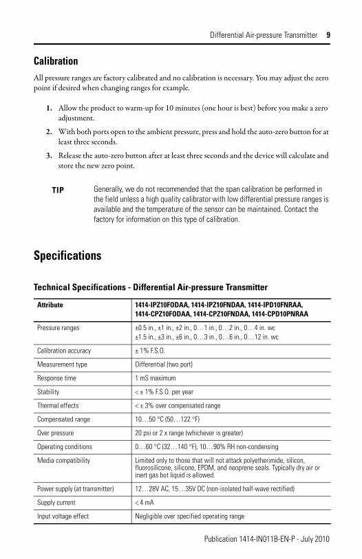
Specifications
TIP Generally, we do not recommended that the span calibration be performed in the field unless a high quality calibrator with low differential pressure ranges is available and the temperature of the sensor can be maintained. Contact the factory for information on this type of calibration.
Technical Specifications - Differential Air-pressure Transmitter
Attribute 1414-IPZ10FODAA, 1414-IPZ10FNDAA, 1414-IPD10FNRAA, 1414-CPZ10FODAA, 1414-CPZ10FNDAA, 1414-CPD10PNRAA
Pressure ranges ±0.5 in., ±1 in., ±2 in., 0…1 in., 0…2 in., 0…4 in. wc±1.5 in., ±3 in., ±6 in., 0…3 in., 0…6 in., 0…12 in. wc
Calibration accuracy ± 1% F.S.O.
Measurement type Differential (two port)
Response time 1 mS maximum
Stability < ± 1% F.S.O. per year
Thermal effects < ± 3% over compensated range
Compensated range 10…50 °C (50…122 °F)
Over pressure 20 psi or 2 x range (whichever is greater)
Operating conditions 0…60 °C (32…140 °F), 10…90% RH non-condensing
Media compatibility Limited only to those that will not attack polyetherimide, silicon, fluorosilicone, silicone, EPDM, and neoprene seals. Typically dry air or inert gas but liquid is allowed.
Power supply (at transmitter) 12…28V AC, 15…35V DC (non-isolated half-wave rectified)
Supply current < 4 mA
Input voltage effect Negligible over specified operating range
Publication 1414-IN011B-EN-P - July 2010

10 Differential Air-pressure Transmitter
Dimensions
Protection circuitry Reverse voltage protected and output limited
Output signal 4…20 mA (2-wire), 0…5V DC or 0…10V DC (3-wire) Pin jumper selectable
Current output drive capability 400 Ω maximum @ 24V DC
Voltage output drive capability 2 KΩ minimum for 0…5V DC signal 10 KΩ minimum for 0…10V DC signal
Zero adjustment Pushbutton auto-zero
Wiring connections Screw terminal block (14…22 AWG)
Pressure Connections Barbed ports for 4.32 mm (0.170 in.) ID flexible tubing
Conduit Connection Access hole for ½ in. NPT conduit or cable gland
Enclosure High Impact Black ABS, plenum rated with optional gasket 127 mm x 84 mm x 53 mm (5.00 in. W x 3.3 in. H x 2.1 in. D)
Weight 159 grams (5.6 oz)
Optional Display 3½ digit, 10.16 mm (0.4 in.) digit height
Technical Specifications - Differential Air-pressure Transmitter
Attribute 1414-IPZ10FODAA, 1414-IPZ10FNDAA, 1414-IPD10FNRAA, 1414-CPZ10FODAA, 1414-CPZ10FNDAA, 1414-CPD10PNRAA
(2.11 in.)53.6mm
(3.32 in.)84.3mm
(4.56 in.)115.8mm
Airflow
Filter
yticoleV wolfriA tcuDgnirotinoM retliF
Publication 1414-IN011B-EN-P - July 2010

Differential Air-pressure Transmitter 11
Notes:
Publication 1414-IN011B-EN-P - July 2010
Rockwell Automation Support
Rockwell Otomasyon Ticaret A.Ş., Kar Plaza İş Merkezi E Blok Kat:6 34752 İçerenköy, İstanbul, Tel: +90 (216) 5698400
Publication 1414-IN011B-EN-P - July 2010 PN-79836
Rockwell Automation provides technical information on the Web to assist you in using its products. At http://www.rockwellautomation.com/support/, you can find technical manuals, a knowledge base of FAQs, technical and application notes, sample code and links to software service packs, and a MySupport feature that you can customize to make the best use of these tools.
For an additional level of technical phone support for installation, configuration and troubleshooting, we offer TechConnect support programs. For more information, contact your local distributor or Rockwell Automation representative, or visit http://www.rockwellautomation.com/support/.
Installation AssistanceIf you experience a problem within the first 24 hours of installation, please review the information that's contained in this manual. You can also contact a special Customer Support number for initial help in getting your product up and running.
New Product Satisfaction ReturnRockwell Automation tests all of its products to ensure that they are fully operational when shipped from the manufacturing facility. However, if your product is not functioning and needs to be returned, follow these procedures.
Documentation Feedback Your comments will help us serve your documentation needs better. If you have any suggestions on how to improve this document, complete this form, publication RA-DU002, available at http://www.rockwellautomation.com/literature/.
United States or Canada 1.440.646.3434
Outside United States or Canada
Use the Worldwide Locator at http://www.rockwellautomation.com/support/americas/phone_en.html, or contact your local Rockwell Automation representative.
United StatesContact your distributor. You must provide a Customer Support case number (call the phone number above to obtain one) to your distributor to complete the return process.
Outside United StatesPlease contact your local Rockwell Automation representative for the return procedure.
Allen-Bradley, Rockwell Software, Rockwell Automation, and TechConnect are trademarks of Rockwell Automation, Inc.
Trademarks not belonging to Rockwell Automation are property of their respective companies.
Supersedes Publication 1414-IN011A-EN-P - October 2005 Copyright © 2010 Rockwell Automation, Inc. All rights reserved. Printed in the U.S.A.