differential pressure / air flow transmitter
TRANSCRIPT
90DS-DPS-X-2-EN-000 - 28 / 11 / 18www.sentera.eu
DPS -2Differential pressure / Air flow transmitter
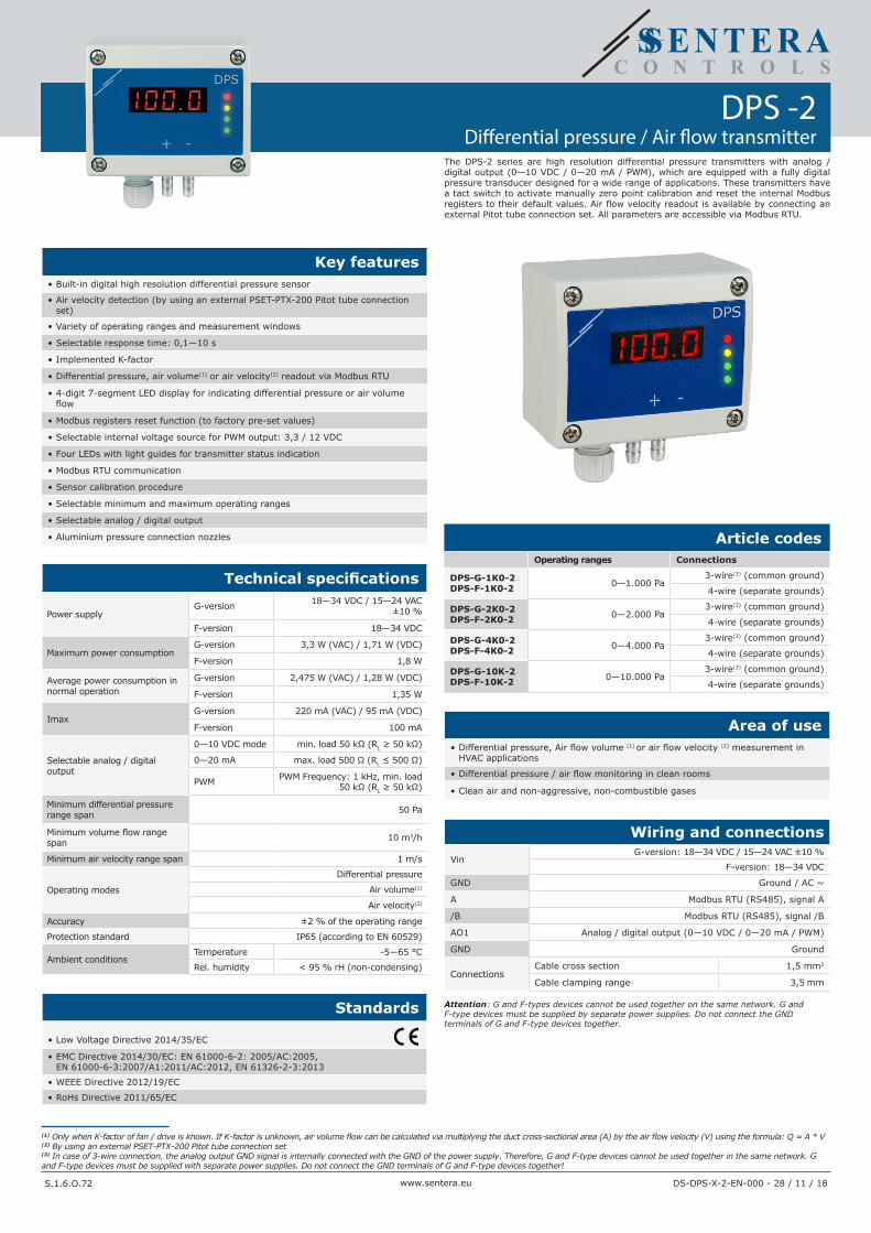
Key features• Built-in digital high resolution differential pressure sensor
• Air velocity detection (by using an external PSET-PTX-200 Pitot tube connection set)
• Variety of operating ranges and measurement windows
• Selectable response time: 0,1—10 s
• Implemented K-factor
• Differential pressure, air volume(1) or air velocity(2) readout via Modbus RTU
• 4-digit 7-segment LED display for indicating differential pressure or air volume flow
• Modbus registers reset function (to factory pre-set values)
• Selectable internal voltage source for PWM output: 3,3 / 12 VDC
• Four LEDs with light guides for transmitter status indication
• Modbus RTU communication
• Sensor calibration procedure
• Selectable minimum and maximum operating ranges
• Selectable analog / digital output
• Aluminium pressure connection nozzles
Technical specifications
Power supplyG-version 18—34 VDC / 15—24 VAC
±10 %
F-version 18—34 VDC
Maximum power consumptionG-version 3,3 W (VAC) / 1,71 W (VDC)
F-version 1,8 W
Average power consumption in normal operation
G-version 2,475 W (VAC) / 1,28 W (VDC)
F-version 1,35 W
ImaxG-version 220 mA (VAC) / 95 mA (VDC)
F-version 100 mA
Selectable analog / digital output
0—10 VDC mode min. load 50 kΩ (RL ≥ 50 kΩ)
0—20 mA max. load 500 Ω (RL ≤ 500 Ω)
PWM PWM Frequency: 1 kHz, min. load 50 kΩ (RL ≥ 50 kΩ)
Minimum differential pressure range span 50 Pa
Minimum volume flow range span 10 m3/h
Minimum air velocity range span 1 m/s
Operating modes
Differential pressure
Air volume(1)
Air velocity(2)
Accuracy ±2 % of the operating range
Protection standard IP65 (according to EN 60529)
Ambient conditionsTemperature -5—65 °C
Rel. humidity < 95 % rH (non-condensing)
Standards
• Low Voltage Directive 2014/35/EC
• EMC Directive 2014/30/EC: EN 61000-6-2: 2005/AC:2005, EN 61000-6-3:2007/A1:2011/AC:2012, EN 61326-2-3:2013
• WEEE Directive 2012/19/EC
• RoHs Directive 2011/65/EC
(1) Only when K-factor of fan / drive is known. If K-factor is unknown, air volume flow can be calculated via multiplying the duct cross-sectional area (A) by the air flow velocity (V) using the formula: Q = A * V(2) By using an external PSET-PTX-200 Pitot tube connection set(3) In case of 3-wire connection, the analog output GND signal is internally connected with the GND of the power supply. Therefore, G and F-type devices cannot be used together in the same network. G and F-type devices must be supplied with separate power supplies. Do not connect the GND terminals of G and F-type devices together!
Article codesOperating ranges Connections
DPS-G-1K0-2DPS-F-1K0-2 0—1.000 Pa
3-wire(3) (common ground)
4-wire (separate grounds)
DPS-G-2K0-2DPS-F-2K0-2 0—2.000 Pa
3-wire(3) (common ground)
4-wire (separate grounds)
DPS-G-4K0-2DPS-F-4K0-2 0—4.000 Pa
3-wire(3) (common ground)
4-wire (separate grounds)
DPS-G-10K-2DPS-F-10K-2 0—10.000 Pa
3-wire(3) (common ground)
4-wire (separate grounds)
Area of use• Differential pressure, Air flow volume (1) or air flow velocity (2) measurement in
HVAC applications
• Differential pressure / air flow monitoring in clean rooms
• Clean air and non-aggressive, non-combustible gases
Wiring and connections
VinG-version: 18—34 VDC / 15—24 VAC ±10 %
F-version: 18—34 VDC
GND Ground / AC ~
A Modbus RTU (RS485), signal A
/B Modbus RTU (RS485), signal /B
AO1 Analog / digital output (0—10 VDC / 0—20 mA / PWM)
GND Ground
ConnectionsCable cross section 1,5 mm2
Cable clamping range 3,5 mm
Attention: G and F-types devices cannot be used together on the same network. G and F-type devices must be supplied by separate power supplies. Do not connect the GND terminals of G and F-type devices together.
The DPS-2 series are high resolution differential pressure transmitters with analog / digital output (0—10 VDC / 0—20 mA / PWM), which are equipped with a fully digital pressure transducer designed for a wide range of applications. These transmitters have a tact switch to activate manually zero point calibration and reset the internal Modbus registers to their default values. Air flow velocity readout is available by connecting an external Pitot tube connection set. All parameters are accessible via Modbus RTU.
S.1.6.O.72
www.sentera.euS.1.6.O.72
DPS -2Differential pressure / Air flow transmitter
DS-DPS-X-2-EN-000 - 28 / 11 / 18
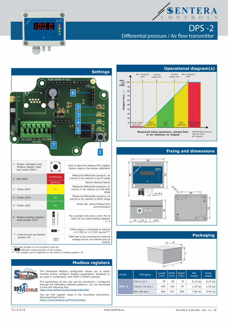
Settings
17
5432
6
1 - Sensor calibration and Modbus register reset tact switch (SW1)
Push to start the Modbus RTU register factory reset or the sensor calibration
2 - Red LED4Continuous Measured differential pressure, air
volume or air velocity is out of range
Blinking Sensor element failure
3 - Yellow LED3 OnMeasured differential pressure, air
volume or air velocity is in the alert range
4 - Green LED2 On Measured differential pressure, air volume or air velocity is within range
5 - Green LED1 On Power OK; active Modbus RTU communication
6 - Modbus holding registers reset jumper (P4)*
12345
Put a jumper onto pins 1 and 2 for at least 20 s to reset holding registers
1—3
7 - Internal pull-up resistor jumper JP1
**PWM output is connected to internal
+3,3 VDC or +12 VDC source***
PWM has to be connected to external
voltage source via external pull-up resistor
* The reset jumper is not included in the set** indicates closed position of the jumper.*** The voltage source depends on the value in holding register 19.
Modbus registers
The Sensistant Modbus configurator allows you to easily monitor and/or configure Modbus parameters. Designed to be used in combination with PDM or DPOM modules.
The parameters of the unit can be monitored / configured through the 3SModbus software platform. You can download it from the following link: https://www.sentera.eu/Downloads/Index/ENG
You can find register maps in the mounting instructions. Download them from: https://www.sentera.eu/Product/Index/
Operational diagram(s)
10
20
30
40
50
60
70
80
90
100
Min. pressure limit
VDC,mA
PWM
Ou
tpu
t [%
]
Measured value (pressure, volume flow or air velocity) vs. Output
Control range min.
Control range max.
Max. pressure limit
Differential pressureVolume FlowAir velocity
Out of rangeLED4 ON
LED2 ON
AlertLED3 ON
AlertLED3 ON
Out of rangeLED4 ON
Fixing and dimensions
DPS
+ _
80
6585
2x Ø 6
46
24 15 10,5
2x Ø 3,449
52
Packaging
H
W
L
Article Packaging Length[mm]
Width[mm]
Height[mm]
Net weight
Gross weight
DPS -2
Unit (1 pc.) 95 85 70 0,13 kg 0,14 kg
Carton (10 pcs.) 495 185 87 1,30 kg 1,40 kg
Box (60 pcs.) 585 375 280 7,80 kg 8,40 kg
92www.sentera.euS.1.6.O.72
DPS -2Differential pressure / Air flow transmitter
DS-DPS-X-2-EN-000 - 28 / 11 / 18
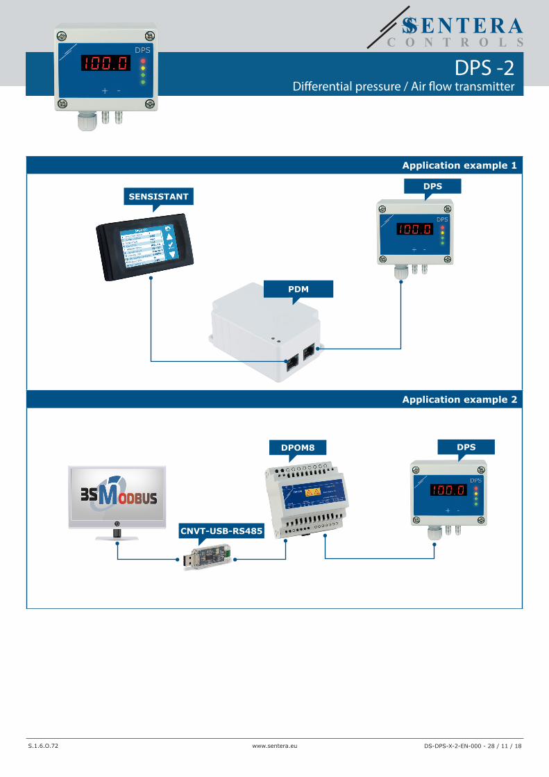
Application example 1
SENSISTANTDPS
PDM
Application example 2
DPOM8
CNVT-USB-RS485
DPS