differential protection schemes and techniques for power ... · furthermore, the differential...
TRANSCRIPT

This is an Open Access article distributed in accordance with the Creative Commons Attribution
Non Commercial (CC-BY-NC-ND 4.0) license, which permits others to copy or share the article,
provided original work is properly cited and that this is not done for commercial purposes. Users
may not remix, transform, or build upon the material and may not distribute the modified material
(http://creativecommons.org/licenses/by-nc/4.0/)
Trivent Publishing
© The Authors, 2016
Available online at http://trivent-publishing.eu/
Engineering and Industry Series
Volume Power Systems, Energy Markets and Renewable Energy Sources in
South-Eastern Europe
Differential Protection Schemes and Techniques
for Power Transformers – Educational Aspects
Nikolina Arapoglou,1 Kiriakos Siderakis
2
1 Department of Electrical Engineering Technological Educational Institute of Crete,
GR-71410 Heraklion, Crete, [email protected] 2 HEDNO (Hellenic Electricity Distribution Network Operator S.A.)
Abstract
A simulation model for the study of the differential protection in the case of
power transformers has been developed. In this direction MATLAB Simulink has
been employed and the operation during fault has been investigated, in the case
of a two phase fault for different windings connections. The simulation results
reveal the influence of the delta winding connection, which limits the
asymmetrical loading experienced.
Keywords
Differential protection; power transformers; non-symmetrical faults; simulink
simulation
I. Introduction
Power Transformers are critical components of electric power systems. Difficult
to repair on site and expensive to replace, they require reliable protection
schemes, in order to ensure availability and fault free operation. One of the most

Arapoglou Nikolina, Siderakis kiriakos
Differential Protection Schemes and Techniques for Power Transformers…
334
widely used protection schemes for power transformers is the differential
protection [1-3]. The operating principle of the differential protection scheme is
in fact the first law of Kirchhoff considering the equivalent of a power
transformer and the node introduced between the primary and secondary
winding. Furthermore, the current flowing into the primary circuit should be
equivalent to the current flowing in the secondary side, in a fault free condition
[1-5].
What is critical in this case is the capability of the system to decide if a fault
incident is inside the protection zone, thus in the transformer or outside [1]. In
the first case, immediate operation of the protection system is required, in order
to achieve operation reliability. On the other hand, if the experienced fault is not
in the transformer, thus outside of the protection zone, no tripping action should
be taken by the system. In this case, other protection systems will have to
encounter the incident.
A special case that is also important is the energization period of the
transformer [1-5]. During this time a difference between the primary and
secondary currents is expected to take place and may be recognized by the
system as an internal fault condition, operation that is not acceptable.
Furthermore, the differential protection system must be able to recognize the
energization current, known as inrush current and should not issue any tripping
action.
Considering the importance of the differential protection systems, in the
substation operation and reliability, it is necessary to include this issue in power
system studies. In this direction, computer simulation programs can facilitate the
investigation of the possible operation modes of a power transformer, in
reference to the differential protection scheme. The first step is analysis of the
transformer operation, in reference to the difference between the primary and
secondary currents in the case of the various power system faults. In this paper,
the results of this study, which is part of an ongoing research project in Crete,
are presented.
II. Differential protection and power system faults
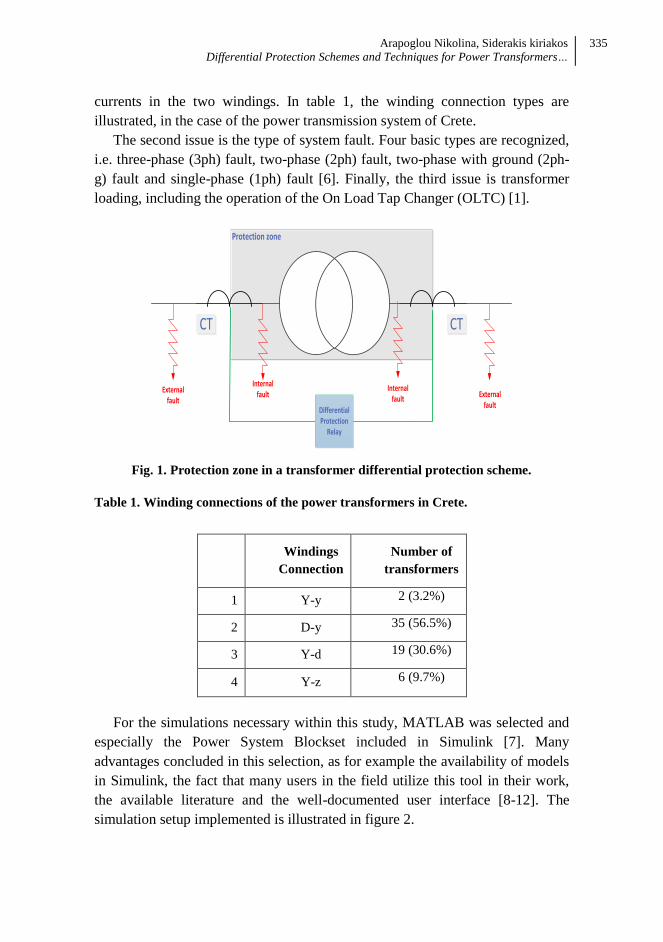
The differential protection scheme of a power transformer is illustrated in figure
1 [1-5]. The protection zone is established by the location of the current
transformers. Furthermore, considering the zone limits, it is possible to
distinguish internal and external outages.
Furthermore, the study must investigate three additional aspects. The first is the
transformer windings connection, which can influence the distribution of
Arapoglou Nikolina, Siderakis kiriakos
Differential Protection Schemes and Techniques for Power Transformers…
335
currents in the two windings. In table 1, the winding connection types are
illustrated, in the case of the power transmission system of Crete.
The second issue is the type of system fault. Four basic types are recognized,
i.e. three-phase (3ph) fault, two-phase (2ph) fault, two-phase with ground (2ph-
g) fault and single-phase (1ph) fault [6]. Finally, the third issue is transformer
loading, including the operation of the On Load Tap Changer (OLTC) [1].
Protection zone
Differential Protection
Relay
CT CT
Internal fault
Internal fault
External fault
External fault
Fig. 1. Protection zone in a transformer differential protection scheme.
Table 1. Winding connections of the power transformers in Crete.
Windings
Connection
Number of
transformers
1 Y-y 2 (3.2%)
2 D-y 35 (56.5%)
3 Y-d 19 (30.6%)
4 Y-z 6 (9.7%)
For the simulations necessary within this study, MATLAB was selected and
especially the Power System Blockset included in Simulink [7]. Many
advantages concluded in this selection, as for example the availability of models
in Simulink, the fact that many users in the field utilize this tool in their work,
the available literature and the well-documented user interface [8-12]. The
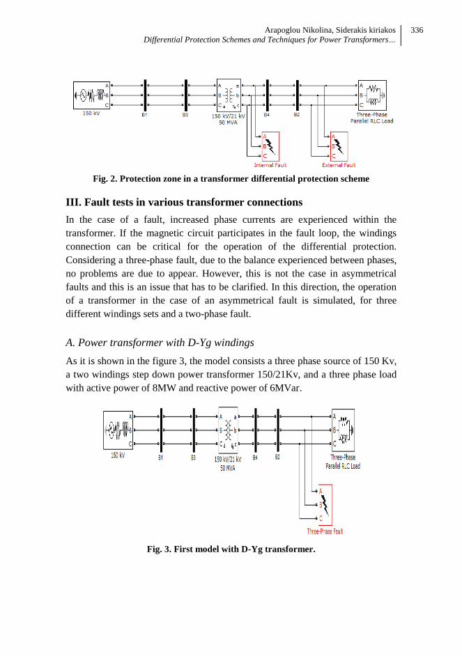
simulation setup implemented is illustrated in figure 2.
Arapoglou Nikolina, Siderakis kiriakos
Differential Protection Schemes and Techniques for Power Transformers…
336
Fig. 2. Protection zone in a transformer differential protection scheme
III. Fault tests in various transformer connections
In the case of a fault, increased phase currents are experienced within the
transformer. If the magnetic circuit participates in the fault loop, the windings
connection can be critical for the operation of the differential protection.
Considering a three-phase fault, due to the balance experienced between phases,
no problems are due to appear. However, this is not the case in asymmetrical
faults and this is an issue that has to be clarified. In this direction, the operation
of a transformer in the case of an asymmetrical fault is simulated, for three
different windings sets and a two-phase fault.
A. Power transformer with D-Yg windings
As it is shown in the figure 3, the model consists a three phase source of 150 Kv,
a two windings step down power transformer 150/21Kv, and a three phase load
with active power of 8MW and reactive power of 6MVar.
Fig. 3. First model with D-Yg transformer.
Arapoglou Nikolina, Siderakis kiriakos
Differential Protection Schemes and Techniques for Power Transformers…
337
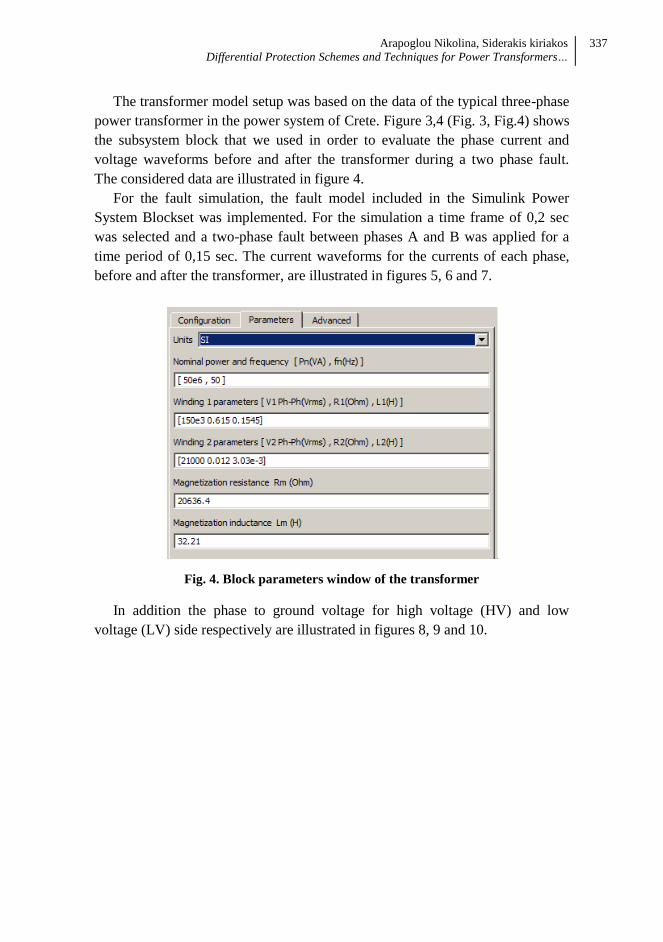
The transformer model setup was based on the data of the typical three-phase
power transformer in the power system of Crete. Figure 3,4 (Fig. 3, Fig.4) shows
the subsystem block that we used in order to evaluate the phase current and
voltage waveforms before and after the transformer during a two phase fault.
The considered data are illustrated in figure 4.
For the fault simulation, the fault model included in the Simulink Power
System Blockset was implemented. For the simulation a time frame of 0,2 sec
was selected and a two-phase fault between phases A and B was applied for a
time period of 0,15 sec. The current waveforms for the currents of each phase,
before and after the transformer, are illustrated in figures 5, 6 and 7.
Fig. 4. Block parameters window of the transformer
In addition the phase to ground voltage for high voltage (HV) and low
voltage (LV) side respectively are illustrated in figures 8, 9 and 10.

Arapoglou Nikolina, Siderakis kiriakos
Differential Protection Schemes and Techniques for Power Transformers…
338
Fig. 5. Current of phase A on HV, LV side
Fig. 6. Current of phase B on HV, LV side

Arapoglou Nikolina, Siderakis kiriakos
Differential Protection Schemes and Techniques for Power Transformers…
339
Fig. 7. Current of phase C on HV, LV side
The currents in the secondary winding are typical for a two-phase fault. The
two participating phases, demonstrate currents of the same level and opposite
phase. Further the current in the third “clear” phase is not influenced by the
fault. However this is not that case in the primary side, where due to the Delta
connection a current is evident also in the “clear” phase, thus can be seen as a
non-symmetrical three-phase fault.

Arapoglou Nikolina, Siderakis kiriakos
Differential Protection Schemes and Techniques for Power Transformers…
340
Fig. 8. Phase voltage A
Regarding the voltage, a drop on the side experiencing the fault is evident at
the beginning and at the end of the fault for both phases A and B. In addition,
incidents of voltage reversals are also evident at the beginning and at the end of
the fault. No remarkable changes can be seen in the primary side, as far as the
voltage is concerned.
Fig. 9. Phase voltage B

Arapoglou Nikolina, Siderakis kiriakos
Differential Protection Schemes and Techniques for Power Transformers…
341
Fig. 10. Phase voltage C
B. Power transformer with Yg-D windings
For the same fault conditions and duration and similar winding connection, the
operation is investigating for the opposite power flow direction. The waveforms
for the currents of each phase, before and after the transformer, are illustrated in
figures 11, 12 and 13. In addition the phase to ground voltage for high voltage
(HV) and low voltage (LV) side respectively are illustrated in figures 14, 15 and
16.

Arapoglou Nikolina, Siderakis kiriakos
Differential Protection Schemes and Techniques for Power Transformers…
342
Fig. 11. Current of phase A on HV, LV side
Fig. 12. Current of phase B on HV, LV side

Arapoglou Nikolina, Siderakis kiriakos
Differential Protection Schemes and Techniques for Power Transformers…
343
Fig. 13. Current of phase C on HV, LV side
In this case also the currents in the secondary winding are typical for a two-
phase fault. The two participating phases, demonstrate currents of the same level
and opposite phase. Further the current in the third “clear” phase is not
influenced by the fault. In the primary side, although it is connected in Y setup, a
current is evident also in the “clear” phase. This is similar behavior to the
previous case and it is evident due to the presence of the delta winding.

Arapoglou Nikolina, Siderakis kiriakos
Differential Protection Schemes and Techniques for Power Transformers…
344
Fig. 14. Phase voltage A
Fig. 15. Phase voltage B

Arapoglou Nikolina, Siderakis kiriakos
Differential Protection Schemes and Techniques for Power Transformers…
345
Fig. 16. Phase voltage C
As far as the voltage is concerned, there are differences in this case. Due to
the fault, the voltage on the faulted phases is zero and in the same time an
overvoltage is observed in the third “clear” phase.
C. Power transformer with Y-Y windings.
For the same fault conditions and duration but different winding connection, the
operation is investigated. The waveforms for the currents of each phase, before
and after the transformer, are illustrated in figures 17, 18 and 19. In addition the
phase to ground voltage for high voltage (HV) and low voltage (LV) side
respectively are illustrated in figures 20, 21 and 22.
In this case also the currents evident on both sides are typical for a two-phase
fault. The two participating phases, demonstrate currents of the same level and
opposite phase. Further the current in the third “clear” phase is not influenced by
the fault. Therefore the absence of the delta winding is the reason that the type of
fault which is the same for both sides. Further the same are valid as far as the
voltage is concerned and only voltage reversal incidents can be found at the
beginning and end of the fault.

Arapoglou Nikolina, Siderakis kiriakos
Differential Protection Schemes and Techniques for Power Transformers…
346
Fig. 17. Current of phase A on HV, LV side
Fig. 18. Current of phase B on HV, LV side

Arapoglou Nikolina, Siderakis kiriakos
Differential Protection Schemes and Techniques for Power Transformers…
347
Fig. 19. Current of phase C on HV, LV side
Fig. 20. Phase voltage A

Arapoglou Nikolina, Siderakis kiriakos
Differential Protection Schemes and Techniques for Power Transformers…
348
Fig. 21. Phase voltage B
Fig. 22. Phase voltage C

Arapoglou Nikolina, Siderakis kiriakos
Differential Protection Schemes and Techniques for Power Transformers…
349
IV. Conclusion
Differential protection is a critical system for the reliable operation of a
substation. In order to develop the knowledge of the transformer operation,
within the scope of academic studies, Simulink has been utilized, in order to
provide an efficient simulation tool. The transformer model and case studies are
developed according to data available in the power system of Crete. Further, the
operation of the transformer in the case of a two phase was investigated, for
different winding connections. The simulation results illustrate the importance of
the delta connection, which decreases the degree of asymmetrical loading from
the secondary to the primary winding. Finally, the developed model can
incorporate also measuring systems and control units to form a complete
differential protection model.
References
[1] Ziegler, Gerhard, “Numerical differential protection: principles and
applications”, 2nd
Edition, Publicis Pub.
[2] A.T. Johns, S.K. Salman, “Digital Protection for Power Systems”, The IEE
Power Series 15.
[3] C. Christopoulos, A. Wright . “Electrical Power System Protection”,
Springer US, 1999.
[4] P.M. Anderson “Power System Protection, The IEEE Series on Power
Engineering”, Wiley – IEEE Press, 1998.
[5] J.J. Winders, “Power transformers: principles and applications”, Marcel
Dekker, 2002.
[6] Mohamed A. Ibrahim, “Disturbance Analysis for Power Systems”, Wiley –
IEEE Press, 2011.
[7] Power system blockset user’s guide, The math works, Version 2.
[8] P.B.Thote, M.B. Daigavane, N.G. Bawane, “Matlab simulink based digital
protection of transformer”, International Journal of Research in Engineering
and Technology Volume: 03 Issue: 02, Feb-2014.
[9] Ihedioha Ahmed C., “Differential Protection for Power Transformer Using
Relay”, International Journal of Trend in Research and Development,
Volume 3(1) Jan-Feb 2016.
[10] Harjit Singh Kainth, Gagandeep Sharma, “A New method for differential
protection in Power transformer”, Journal of Electrical and Electronics
Engineering, Volume 9, Issue 2 Ver. IV (Mar – Apr. 2014), 64-70.

Arapoglou Nikolina, Siderakis kiriakos
Differential Protection Schemes and Techniques for Power Transformers…
350
[11] Behrooz Vahidi, Vahid Farahani, “Modelling and simulation the current
transformers for measuring current harmonics using Matlab-Simulink”
,international review of modelling and simulations, Volume 4, N.4 (August
2011).
[12] Harish Balaga, Neha Gupta Devendra Nath Vishwakarma, “GA trained
parallel hidden layered ANN based differential protection of three phase
power transformer”, Electrical power and energy systems, Volume 67,
(May 2015), 286-297.