diffraction enhanced imaging at x15a · diffraction enhanced imaging and other biomedical...
TRANSCRIPT
Diffraction Enhanced Imaging and Other Biomedical Applications of NSLS-II
Z. ZhongNational Synchrotron Light Source, Brookhaven National Lab
Collaborators: D. Chapman2, D. Connor3, A. Dilmanian6, M. Hasnah2, M. Kiss3, J. Li4, C. Muehleman4, O. Oltulu2, C. Parham5, E. Pisano5, D. Sayers3
2. Illinois Institute of Technology/University of Saskachewen3. Dept. Physics, North Carolina State University4. Rush-Presbyterian-St. Luke’s Medical Center5. Dept. Radiology, University of North Carolina, Chapel Hil6. Medical Dept., Brookhaven National Lab
Background
• Diffraction Enhanced Imaging (DEI) was developed, in 1995 at the NSLS, to explore the use of synchrotron radiation for mammography.
• Used for mammography research since 1995 -> Chris Parham’s talk.
• Dedicated facility built at X15A in 1998.• US Patent issued in 1999.• Cartilage imaging since 1999 -> Carol Muehleman’s talk.• Other facilities, Daresbury, Elettra, ESRF, HASYLAB, KEK,
Spring8, have also developed DEI capability ... Most more advanced than NSLS.
• Canadian Light Source, being built at Saskatoon, plans for DEI/Medical Imaging facility.

Synchrotron Radiography and DEIObject
Si(333) Double Crystal Monochromator
Radiography
Si(333) Bragg Analyzer
Diffracted Beam
Detector - Image Plate
DEI
Synchrotron Beam
Experimental Setup at NSLS X15A
X-rays are analyzed in angle, using perfect silicon crystal, after passing through object.

How does DEI work?• DEI utilizes the small range of angles (a few microradians) over which a perfect crystal reflects X-rays. • The analyser functions as an extremely narrow slit. • If the analyser angle is set half way on the rocking curve (θB±∆θD/2), rays that are deviated in the object will be reflected with either a greater or lower efficiency than 0.5. • The steep slope of the rocking curve acts as a angle-intensity converter and reveals X-ray refraction which carry different information to conventional absorption images.
D. Chapman, W. Thomlinson, et. al., Phys. Med. Biol., 42 (1997) 2015-2025
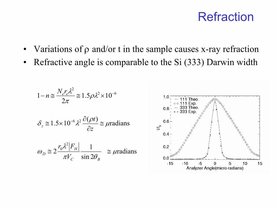
Refraction
• Variations of ρ and/or t in the sample causes x-ray refraction• Refractive angle is comparable to the Si (333) Darwin width
622
105.12
1 −×≅≅− ρλπλeerNn
radians)(105.1 26 µρλδ ≅∂
∂×≅ −
zt
z
BC
HD V
Frθπ
λω
2sin12
20≅ radiansµ≅

Refraction contrast in Nylon fiber
Radiograph
Analyzer on Shouder of
Rocking curve
Peak
0.7 mm
Diameter
0.55 mm 0.2 mm 0.1 mm
Nylon fiber simulates density variation in soft tissue
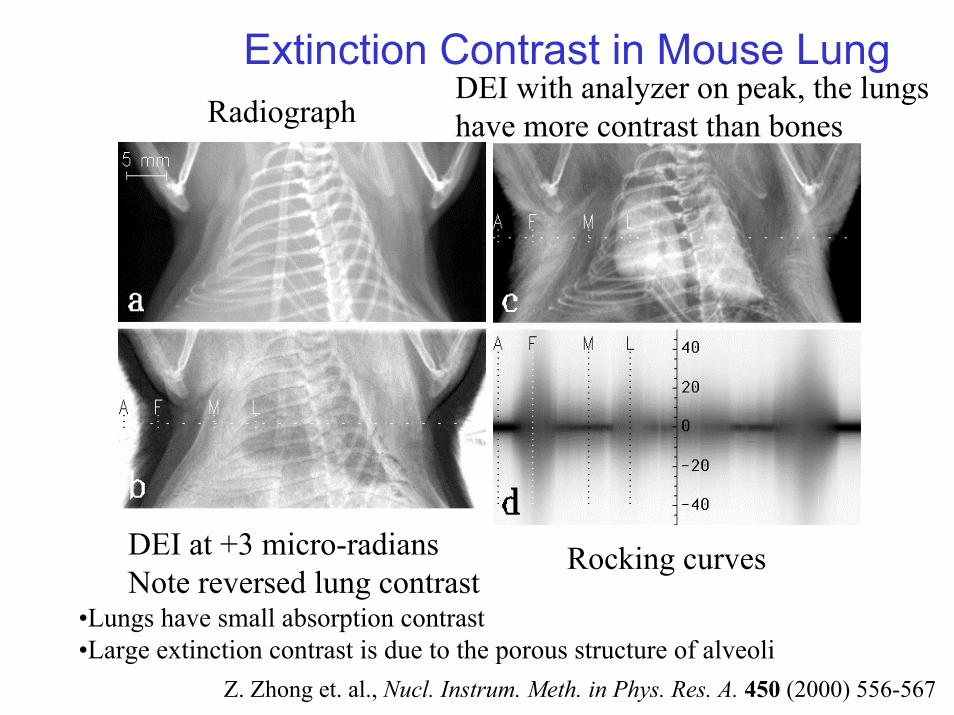
Extinction Contrast in Mouse Lung Radiograph
DEI with analyzer on peak, the lungshave more contrast than bones
DEI at +3 micro-radiansNote reversed lung contrast
Rocking curves
•Lungs have small absorption contrast •Large extinction contrast is due to the porous structure of alveoli
Z. Zhong et. al., Nucl. Instrum. Meth. in Phys. Res. A. 450 (2000) 556-567

DEI Sources of Contrast• Normal Absorption - same as from conventional
radiography• Refraction Contrast - sensitive to refractive index gradients
at the imaging energy– Characterized by a shift in peak position of the rocking curve– Edge enhancement without computer processing the image
• Extinction Contrast – Characterized by broadening of rocking curve - sensitive to structure
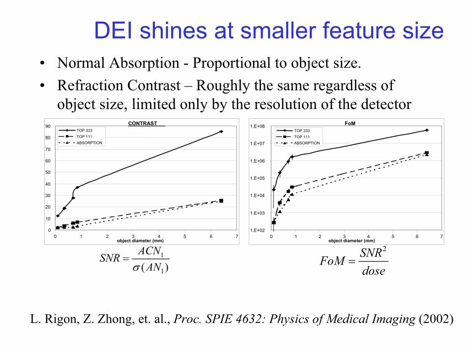
DEI shines at smaller feature size• Normal Absorption - Proportional to object size.• Refraction Contrast – Roughly the same regardless of
object size, limited only by the resolution of the detectorCONTRAST
0
10
20
30
40
50
60
70
80
90
0 1 2 3 4 5 6 7object diameter (mm)
TOP 333TOP 111ABSORPTION
)( 1
1
ANACNSNRσ
=
FoM
1.E+02
1.E+03
1.E+04
1.E+05
1.E+06
1.E+07
1.E+08
0 1 2 3 4 5 6 7object diameter (mm)
TOP 333TOP 111ABSORPTION
doseSNRFoM
2
=
L. Rigon, Z. Zhong, et. al., Proc. SPIE 4632: Physics of Medical Imaging (2002)

DEI does not rely on absorption (=dose)• DEI can be implemented at near zero dose by utilizing
higher-energy x-rays.• 5 mRads exposure to detector
– @18keV @ 30keV– 2.65x10⁷ 7.85x10⁷ photons / pixel
onto detector– 0.010 0.175 transmission
factor through 5cm thick tissue
– 2.65x10⁹ 4.49x10⁸ photons / pixel at front surface of tissue
– 0.450 0.029 Rads skin entry dose
• 15.5 x smaller dose at 30keV compared to 18keV
0 20 40 60 80 100
1.00
0.10
0.01
0.05
0.02
0.50
0.20
Skin
Ent
ry D
ose
(Rad
s)
Imaging Energy (keV)
Skin Entry Dose vs. Imaging Energy5 mRad detector exposure through 5cm tissue

DEI Setup at NSLS X15A
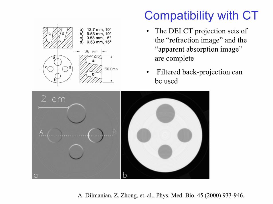
Compatibility with CT• The DEI CT projection sets of
the “refraction image” and the “apparent absorption image” are complete
• Filtered back-projection can be used
A. Dilmanian, Z. Zhong, et. al., Phys. Med. Bio. 45 (2000) 933-946.
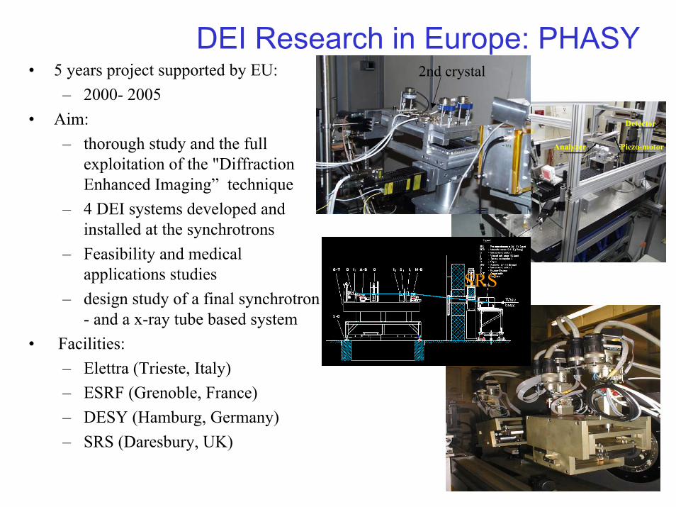
DEI Research in Europe: PHASY• 5 years project supported by EU:
– 2000- 2005• Aim:
– thorough study and the full exploitation of the "Diffraction Enhanced Imaging” technique
– 4 DEI systems developed and installed at the synchrotrons
– Feasibility and medical applications studies
– design study of a final synchrotron - and a x-ray tube based system
• Facilities:– Elettra (Trieste, Italy)– ESRF (Grenoble, France)– DESY (Hamburg, Germany)– SRS (Daresbury, UK)
Setup
DEI-MonoIC
Sample Stage
Analyzer Piezo-motor
Detector
2nd crystal
SRS
Other Biomedical applications• Cancer Therapy and Radiobiology Research: Microbeam
Radiation Therapy (MRT), Photon Activation Therapy• Cancer Biology• Tissue specific tomography• Musculoskeletal Imaging -> Tunability• Dual-energy K-edge subtraction Imaging -> Contrast
agent, functional imaging, perfusion• Development of new imaging modalities, functional
contrast agent development, Neurosciences, protein and cellular localization.

Other facilitiesSpring-8
SYRMEP, Elettra
Control room Instrumentation
Diagnostic area
Radiologist roomExperimental room
Patient room

ESRF BIOMEDICAL BEAMLINE
ID17
ESRF
ID17

Summary
• DEI of human breast and knee specimens, as well as in vivo animals, show:
• DEI refraction highlights boundaries between different tissue types (e.g. breast tissue and tumor), provides information on lesion border detail and associated features that are not detected by conventional imaging -> early diagnosis of breast cancer.
• lungs were substantially highlighted in the “apparent absorption” image -> relevant for diagnosis of early stages of emphysema and edema.
• DEI differentiates between normal and damaged cartilage within knee joint. -> Potential for assessment of cartilage damage in vivo.
2002-3 X15A DEI Publications• 1. C. Muehleman,L.D. Chapman, K. E. Kuettner, J Rieff, J A. Mollenhauer, K. Massuda, and Z. Zhong,
“Radiography of Rabbit Articular Cartilage with Diffraction Enhanced Imaging”, Anatomical Record 272A(2003) 392-397.
• 2. J. Li, Z. Zhong, R. Litdke, K. E. Kuettner, C. Peterfy, E. Aleyeva, and C. Muehleman, “Radiography of Soft Tissue of the Foot and Ankle with Diffraction Enhanced Imaging”, J. Anatomy 202 (2003) 463-470.
• 3. M. Z. Kiss, D. E. Sayers and Zhong Zhong, “Measurement of image contrast using diffraction enhanced imaging”, Phys. Med. Bio. 48 (2003) 325-340.
• 4. M. Hasnah, O. Oltulu, Z. Zhong, and D. Chapman, “Single Exposure Simultaneous Diffraction Enhanced Imaging”, Nucl. Instrum. Meth. Phys. Res A 492 (2002) 236-240.
• 5. Z. Zhong, D. Chapman, D. Connor, A. Dilmanian, N. Gmür, M. Hasnah, R. E. Johnston, M. Kiss, J. Li, C. Muehleman, O. Oltulu, C. Parham, E. Pisano, L. Rigon, D. Sayers, W. Thomlinson, M. Yaffe, and H. Zhong, “Diffraction Enhanced Imaging of Soft Tissues”, Syn. Rad. News 15 (6) (2002) 27-34.
• 6. M.O. Hasnah, Z. Zhong, O. Oltulu, E. Pisano, R.E. Johnston, D. Sayers, W. Thomlinson and D. Chapman, “Diffraction Enhanced Imaging Contrast Mechanisms in Breast Cancer Specimens”, Medical Physics 29 (2002) 2216-2221.
• 7. C. Muehleman, M. Whiteside, Z. Zhong, J. Mollenhauer, M. Aurich, K.E. Kuettner and L.D. Chapman, “Diffraction enhanced imaging for articular cartilage”, Biophys. J. 82 (2002) 2292.
• 8. M. Z. Kiss, D. E. Sayers and Z. Zhong, “Comparison of X-ray detectors for a diffraction enhanced imaging system”, Nucl. Instrum. Meth. Phys. Res., A491 (2002) 280-290.
• 9. M. Hasnah, O. Oltulu, Z. Zhong and D. Chapman, “Application of Absorption and Refraction Matching Techniques for Diffraction Enhanced Imaging”, Rev. Sci. Instrum. 73 (2002) 1657-1659.
• 10. J. Mollenhauer, M. Aurich, Z. Zhong, C. Muehleman, A. A. Cole, M. Hasnah, O. Oltulu, K. E. Kuettner, A. Margulis and L. D. Chapman, "Diffraction Enhanced X-ray Imaging of Articular Cartilage", J. Osteoarthritis and Cartilage, 10 (2002) 168-171.