diffrential ptn relay
TRANSCRIPT
37137A
ESDR 4 Current Differential Protection Relay
Manual
Manual 37137A
Manual 37137A ESDR 4 - Current Differential Protection Relay
WARNING Read this entire manual and all other publications pertaining to the work to be performed before install-ing, operating, or servicing this equipment. Practice all plant and safety instructions and precautions. Failure to follow instructions can cause personal injury and/or property damage. The engine, turbine, or other type of prime mover should be equipped with an overspeed (overtempera-ture, or overpressure, where applicable) shutdown device(s), that operates totally independently of the prime mover control device(s) to protect against runaway or damage to the engine, turbine, or other type of prime mover with possible personal injury or loss of life should the mechanical-hydraulic gov-ernor(s) or electric control(s), the actuator(s), fuel control(s), the driving mechanism(s), the linkage(s), or the controlled device(s) fail.
CAUTION To prevent damage to a control system that uses an alternator or battery-charging device, make sure the charging device is turned off before disconnecting the battery from the system. Electronic controls contain static-sensitive parts. Observe the following precautions to prevent dam-age to these parts. • Discharge body static before handling the control (with power to the control turned off, contact a
grounded surface and maintain contact while handling the control). • Avoid all plastic, vinyl, and Styrofoam (except antistatic versions) around printed circuit boards. • Do not touch the components or conductors on a printed circuit board with your hands or with
conductive devices. Important definitions
WARNING Indicates a potentially hazardous situation that, if not avoided, could result in death or serious injury.
CAUTION Indicates a potentially hazardous situation that, if not avoided, could result in damage to equipment.
NOTE Provides other helpful information that does not fall under the warning or caution categories.
Woodward Governor Company reserves the right to update any portion of this publication at any time. Information provided by Wood-ward Governor Company is believed to be correct and reliable. However, Woodward Governor Company assumes no responsibility unless otherwise expressly undertaken.
© Woodward Governor Company
All Rights Reserved.
Page 2/34 © Woodward
Manual 37137A ESDR 4 - Current Differential Protection Relay
© Woodward Page 3/34
Contents
CHAPTER 1. GENERAL INFORMATION.........................................................................................5 CHAPTER 2. ELECTROSTATIC DISCHARGE AWARENESS .............................................................6 CHAPTER 3. WIRING..................................................................................................................7 Wiring diagram........................................................................................................................................8 Power Supply ..........................................................................................................................................9 Measuring inputs...................................................................................................................................10 Discrete inputs ......................................................................................................................................11 Relay outputs ........................................................................................................................................12 CHAPTER 4. FUNCTIONAL DESCRIPTION ..................................................................................13 Introduction ...........................................................................................................................................13 Functional description ...........................................................................................................................14
Monitoring of the differential current ...........................................................................................14 Tripping characteristic.................................................................................................................14 Control inputs..............................................................................................................................16 Relays .........................................................................................................................................16
CHAPTER 5. DISPLAY AND OPERATING ELEMENTS ...................................................................17 Short description of LED's and buttons.................................................................................................17
LEDs ...........................................................................................................................................17 Buttons........................................................................................................................................17 Miscellaneous .............................................................................................................................17
LEDs......................................................................................................................................................18 Buttons ..................................................................................................................................................18 LC-Display.............................................................................................................................................19 CHAPTER 6. CONFIGURATION ..................................................................................................20 Introduction ...........................................................................................................................................20 Basic data .............................................................................................................................................21 Protection ..............................................................................................................................................22 CHAPTER 7. COMMISSIONING ..................................................................................................24 APPENDIX A. DIMENSIONS.......................................................................................................26 APPENDIX B. LIST OF PARAMETERS ........................................................................................27 APPENDIX C. TECHNICAL DATA ...............................................................................................28 APPENDIX D. SERVICE OPTIONS..............................................................................................29 Product service options.........................................................................................................................29 Returning equipment for repair .............................................................................................................29
Packing a control ........................................................................................................................30 Return authorization number RAN .............................................................................................30
Replacement parts ................................................................................................................................30 How to contact Woodward ....................................................................................................................31 Engineering services.............................................................................................................................32 Technical assistance.............................................................................................................................33
Manual 37137A ESDR 4 - Current Differential Protection Relay
Page 4/34 © Woodward
Figures and Tables
Figures Figure 3-1: Wiring diagram ....................................................................................................................................................... 8 Figure 3-2: Power Supply .......................................................................................................................................................... 9 Figure 3-3: CT (transducer) inputs........................................................................................................................................... 10 Figure 3-4: Discrete inputs....................................................................................................................................................... 11 Figure 3-5: Relay outputs ........................................................................................................................................................ 12 Figure 4-1: Protection principle ............................................................................................................................................... 13 Figure 4-2: Characteristic ........................................................................................................................................................ 15 Figure 5-1: Front panel ............................................................................................................................................................ 17 Figure 7-1: Dimensions............................................................................................................................................................ 26
Manual 37137A ESDR 4 - Current Differential Protection Relay
© Woodward Page 5/34
Chapter 1. General Information
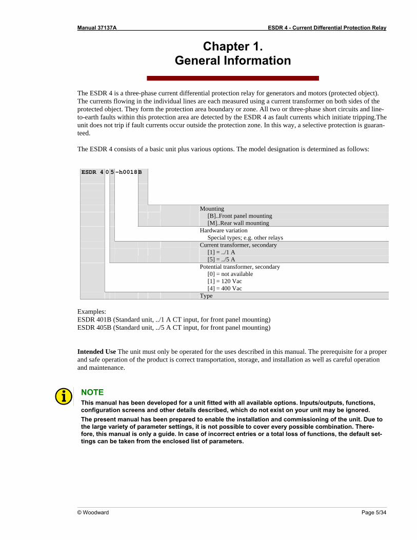
The ESDR 4 is a three-phase current differential protection relay for generators and motors (protected object). The currents flowing in the individual lines are each measured using a current transformer on both sides of the protected object. They form the protection area boundary or zone. All two or three-phase short circuits and line-to-earth faults within this protection area are detected by the ESDR 4 as fault currents which initiate tripping.The unit does not trip if fault currents occur outside the protection zone. In this way, a selective protection is guaran-teed. The ESDR 4 consists of a basic unit plus various options. The model designation is determined as follows: ESDR 4 0 5 -h0018 B
Mounting
[B]..Front panel mounting [M]..Rear wall mounting
Hardware variation
Special types; e.g. other relays
Current transformer, secondary
[1] = ../1 A [5] = ../5 A
Potential transformer, secondary [0] = not available [1] = 120 Vac [4] = 400 Vac
Type Examples: ESDR 401B (Standard unit, ../1 A CT input, for front panel mounting) ESDR 405B (Standard unit, ../5 A CT input, for front panel mounting) Intended Use The unit must only be operated for the uses described in this manual. The prerequisite for a proper and safe operation of the product is correct transportation, storage, and installation as well as careful operation and maintenance.
NOTE This manual has been developed for a unit fitted with all available options. Inputs/outputs, functions, configuration screens and other details described, which do not exist on your unit may be ignored. The present manual has been prepared to enable the installation and commissioning of the unit. Due to the large variety of parameter settings, it is not possible to cover every possible combination. There-fore, this manual is only a guide. In case of incorrect entries or a total loss of functions, the default set-tings can be taken from the enclosed list of parameters.
Manual 37137A ESDR 4 - Current Differential Protection Relay
Page 6/34 © Woodward
Chapter 2. Electrostatic Discharge Awareness
All electronic equipment is static-sensitive, some components more than others. To protect these components from static damage, you must take special precautions to minimize or eliminate electrostatic discharges. Follow these precautions when working with or near the control. 1. Before performing maintenance on the electronic control, discharge the static electricity on your body to
ground by touching and holding a grounded metal object (pipes, cabinets, equipment, etc.). 2. Avoid the build-up of static electricity on your body by not wearing clothing made of synthetic materials.
Wear cotton or cotton-blend materials as much as possible because these do not store static electric char-ges as much as synthetics.
3. Keep plastic, vinyl, and Styrofoam materials (such as plastic or Styrofoam cups, cup holders, cigarette
packages, cellophane wrappers, vinyl books or folders, plastic bottles, and plastic ash trays) away from the control, the modules, and the work area as much as possible.
4. Opening the control cover may void the unit warranty.
Do not remove the Printed Circuit Board (PCB) from the control cabinet unless absolutely necessary. If you must remove the PCB from the control cabinet, follow these precautions:
• Ensure that the device is completely de-energized (all connectors must be disconnected).
• Do not touch any part of the PCB except the edges.
• Do not touch the electrical conductors, connectors, or components with conductive devices with your
hands.
• When replacing a PCB, keep the new PCB in the protective antistatic bag it comes in until you are ready to install it. Immediately after removing the old PCB from the control cabinet, place it in the protective antistatic bag.
CAUTION To prevent damage to electronic components caused by improper handling, read and observe the pre-cautions in Woodward manual 82715, Guide for Handling and Protection of Electronic Controls, Printed Circuit Boards, and Modules.
Manual 37137A ESDR 4 - Current Differential Protection Relay
© Woodward Page 7/34
Chapter 3. Wiring
CAUTION A circuit breaker must be provided near the unit and in a position easily accessible to the operator. This must also bear a sign identifying it as an isolating switch for the unit.
NOTE Inductive devices connected to the system (such as operating current coils, undervoltage tripping units, or auxiliary/power contacts) must be connected to a suitable interference suppressor.
Manual 37137A ESDR 4 - Current Differential Protection Relay
Page 8/34 © Woodward
Wiring diagram ≡≡≡≡≡≡≡≡≡≡≡≡≡≡≡≡≡≡≡≡≡≡≡≡≡
Current IL1 transducer set 2
Current IL2 transducer set 2
Current IL3 transducer set 2
Current IL3 transducer set 1
Current IL2 transducer set 1
Current IL1 transducer set 1
35
Subject to technical modifications.
The t
rans
duce
r rati
o is a
djusta
blein
the di
splay
.
L1 L2 L3
Trans
duce
r set
1
3025
2627
2829
G
The t
rans
duce
r rati
o is a
djusta
blein
the di
splay
.
Trans
duce
r set
2
3633
3431
32
18Acknowledgement
Relay 1Tripping
Relay 2Tripping
Relay 3Ready for operation
Relay 4Warning
0 Vdc
24 Vdc
Common
Configuration
61
23
45
2004-10-01 | ESDR 4 Wiring Diagram e4ww-4004-ap.skf
1211
109
78
1316
1514
17
Blocking 19
ESDR
4 -
Curre
nt D
iffer
entia
l Pro
tect
ion
Rela
y
N/C
N/C
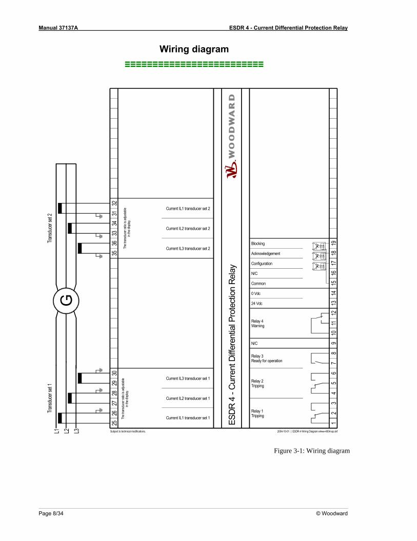
Figure 3-1: Wiring diagram
Manual 37137A ESDR 4 - Current Differential Protection Relay
© Woodward Page 9/34
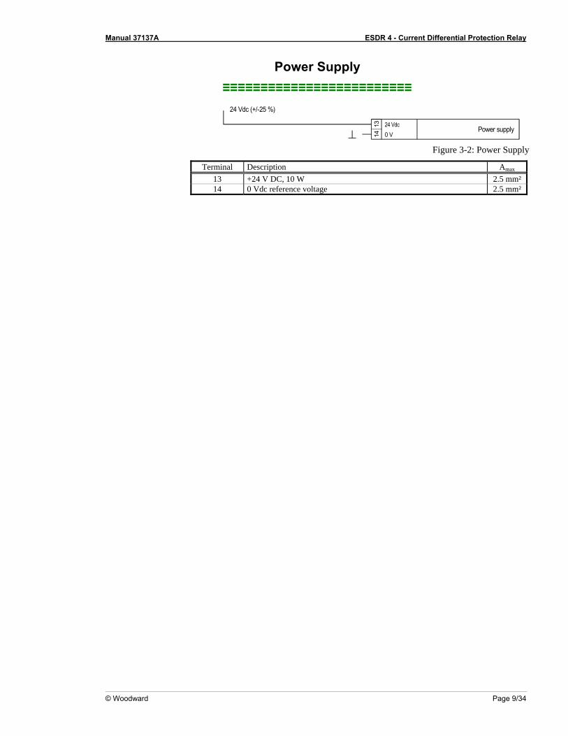
Power Supply ≡≡≡≡≡≡≡≡≡≡≡≡≡≡≡≡≡≡≡≡≡≡≡≡≡
24 Vdc (+/-25 %)
1314
24 Vdc0 V
Power supply
Figure 3-2: Power Supply
Terminal Description Amax 13 +24 V DC, 10 W 2.5 mm² 14 0 Vdc reference voltage 2.5 mm²
Manual 37137A ESDR 4 - Current Differential Protection Relay
Page 10/34 © Woodward
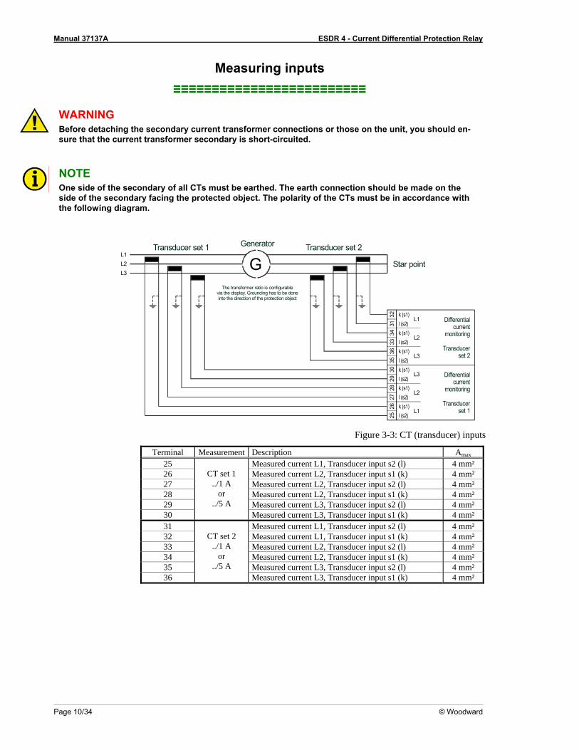
Measuring inputs ≡≡≡≡≡≡≡≡≡≡≡≡≡≡≡≡≡≡≡≡≡≡≡≡≡
WARNING Before detaching the secondary current transformer connections or those on the unit, you should en-sure that the current transformer secondary is short-circuited.
NOTE One side of the secondary of all CTs must be earthed. The earth connection should be made on the side of the secondary facing the protected object. The polarity of the CTs must be in accordance with the following diagram.
Star point
Transducer set 1 Generator Transducer set 2
Differentialcurrent
monitoring
Transducerset 1
Differentialcurrent
monitoring
Transducerset 2
L2L1
L3G
l (s2)k (s1)
L2l (s2)k (s1)
l (s2)k (s1)
l (s2)k (s1)
L3
L2
L1
l (s2)k (s1)
l (s2)k (s1)
2526
3029
2827
3536
3334
3132 L1
L3
The transformer ratio is configurablevia the display. Grounding has to be doneinto the direction of the protection object
Figure 3-3: CT (transducer) inputs
Terminal Measurement Description Amax 25 Measured current L1, Transducer input s2 (l) 4 mm² 26 Measured current L2, Transducer input s1 (k) 4 mm² 27 Measured current L2, Transducer input s2 (l) 4 mm² 28 Measured current L2, Transducer input s1 (k) 4 mm² 29 Measured current L3, Transducer input s2 (l) 4 mm² 30
CT set 1 ../1 A
or ../5 A
Measured current L3, Transducer input s1 (k) 4 mm² 31 Measured current L1, Transducer input s2 (l) 4 mm² 32 Measured current L1, Transducer input s1 (k) 4 mm² 33 Measured current L2, Transducer input s2 (l) 4 mm² 34 Measured current L2, Transducer input s1 (k) 4 mm² 35 Measured current L3, Transducer input s2 (l) 4 mm² 36
CT set 2 ../1 A
or ../5 A
Measured current L3, Transducer input s1 (k) 4 mm²
Manual 37137A ESDR 4 - Current Differential Protection Relay
© Woodward Page 11/34
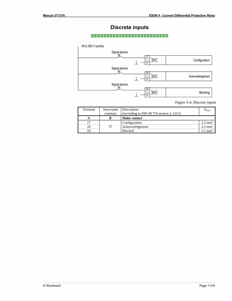
Discrete inputs ≡≡≡≡≡≡≡≡≡≡≡≡≡≡≡≡≡≡≡≡≡≡≡≡≡
Signal device
Signal device
Signal device
Blocking
Acknowledgment
Configuration
18 to 250 V (ac/dc)
1715
1815
1915
Figure 3-4: Discrete inputs
Terminal Associatedcommon
Description (according to DIN 40 719 section 3, 5.8.3)
Amax
A B Make contact 17 Configuration 2.5 mm² 18 Acknowledgement 2.5 mm² 19
15 Blocked 2.5 mm²

Manual 37137A ESDR 4 - Current Differential Protection Relay
Page 12/34 © Woodward
Relay outputs ≡≡≡≡≡≡≡≡≡≡≡≡≡≡≡≡≡≡≡≡≡≡≡≡≡
max. 250 Vac
AB
Relay output
Relay outputexternal device
external device
external device
CD
E
Relay outputexternal device
external device
FG
H
Figure 3-5: Relay outputs
Terminal Amax Root Make-contact
A B
Description
7 8 Relay 3 – Ready for operation 2.5 mm²
Make-Contact
Root Break-contact
C D E 3 2 1 Relay 1 –Trip 2.5 mm² 6 5 4 Relay 2 –Trip 2.5 mm²
Root Make-contact
Break-contact
F G H 11 10 12 Relay 4 – Warning 2.5 mm²
Manual 37137A ESDR 4 - Current Differential Protection Relay
© Woodward Page 13/34
Chapter 4. Functional Description
Introduction ≡≡≡≡≡≡≡≡≡≡≡≡≡≡≡≡≡≡≡≡≡≡≡≡≡
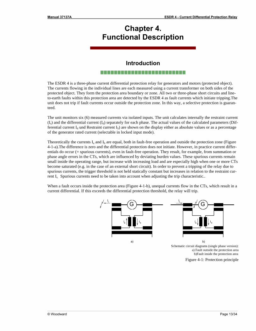
The ESDR 4 is a three-phase current differential protection relay for generators and motors (protected object). The currents flowing in the individual lines are each measured using a current transformer on both sides of the protected object. They form the protection area boundary or zone. All two or three-phase short circuits and line-to-earth faults within this protection area are detected by the ESDR 4 as fault currents which initiate tripping.The unit does not trip if fault currents occur outside the protection zone. In this way, a selective protection is guaran-teed. The unit monitors six (6) measured currents via isolated inputs. The unit calculates internally the restraint current (Is) and the differential current (Id) separately for each phase. The actual values of the calculated parameters (Dif-ferential current Id und Restraint current IS) are shown on the display either as absolute values or as a percentage of the generator rated current (selectable in locked input mode). Theoretically the currents Ia and Ib are equal, both in fault-free operation and outside the protection zone (Figure 4-1-a).The difference is zero and the differential protection does not initiate. However, in practice current differ-entials do occur (= spurious currents), even in fault-free operation. They result, for example, from summation or phase angle errors in the CTs, which are influenced by deviating burden values. These spurious currents remain small inside the operating range, but increase with increasing load and are especially high when one or more CTs become saturated (e.g. in the case of an external short circuit). In order to prevent a tripping of the relay due to spurious currents, the trigger threshold is not held statically constant but increases in relation to the restraint cur-rent Is. Spurious currents need to be taken into account when adjusting the trip characteristic.. When a fault occurs inside the protection area (Figure 4-1-b), unequal currents flow in the CTs, which result in a current differential. If this exceeds the differential protection threshold, the relay will trip.
G
I I
ILG
I I
IL
a
a)
b
b)
a b
Schematic circuit diagrams (single phase version):
a) Fault outside the protection area b)Fault inside the protection area
Figure 4-1: Protection principle
Manual 37137A ESDR 4 - Current Differential Protection Relay
Page 14/34 © Woodward
Functional description ≡≡≡≡≡≡≡≡≡≡≡≡≡≡≡≡≡≡≡≡≡≡≡≡≡
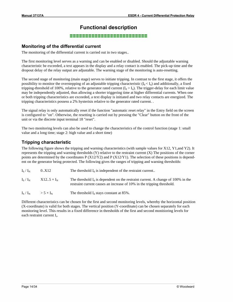
Monitoring of the differential current The monitoring of the differential current is carried out in two stages.. The first monitoring level serves as a warning and can be enabled or disabled. Should the adjustable warning characteristic be exceeded, a text appears in the display and a relay contact is enabled. The pick-up time and the dropout delay of the relay output are adjustable. The warning stage of the monitoring is auto-resetting. The second stage of monitoring (main stage) serves to initiate tripping. In contrast to the first stage, it offers the possibility to monitor the overstepping of an adjustable tripping characteristic (Id < In) and additionally, a fixed tripping-threshold of 100%, relative to the generator rated current (Id > In). The trigger-delay for each limit value may be independently adjusted, thus allowing a shorter triggering time at higher differential currents. When one or both tripping characteristics are exceeded, a text display is initiated and two relay contacts are energized. The tripping characteristics possess a 2% hysterisis relative to the generator rated current. . The signal relay is only automatically reset if the function "automatic reset relay" in the Entry field on the screen is configured to "on". Otherwise, the resetting is carried out by pressing the "Clear" button on the front of the unit or via the discrete input terminal 18 "reset". The two monitoring levels can also be used to change the characteristics of the control function (stage 1: small value and a long time; stage 2: high value and a short time)
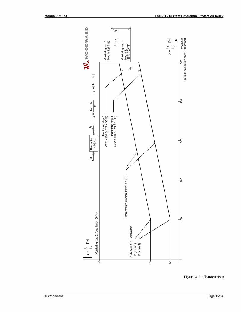
Tripping characteristic The following figure shows the tripping and warning characteristics (with sample values for X12, Y1,and Y2). It represents the tripping and warning thresholds (Y) relative to the restraint current (X) The positions of the corner points are determined by the coordinates P (X12/Y2) and P (X12/Y1). The selection of these positions is depend-ent on the generator being protected. The following gives the ranges of tripping and warning thresholds: IS / IN 0..X12 The threshold Id is independent of the restraint current.. IS / IN X12..5 × IN The threshold Id is dependent on the restraint current. A change of 100% in the
restraint current causes an increase of 10% in the tripping threshold. IS / IN > 5 × IN The threshold Id stays constant at 85%. Different characteristics can be chosen for the first and second monitoring levels, whereby the horizontal position (X-coordinate) is valid for both stages. The vertical position (Y-coordinate) can be chosen separately for each monitoring level. This results in a fixed difference in thresholds of the first and second monitioring levels for each restraint current Is.
Manual 37137A ESDR 4 - Current Differential Protection Relay
© Woodward Page 15/34
Mon
itorin
g st
ep 1
(X12
= 1
00 %
/ Y1
= 1
0 %
)
Mon
itorin
g st
ep 2
(X12
= 1
00 %
/ Y2
= 3
5 %
)
Pro
tect
edob
ject
100
200
Char
acte
ristic
gra
dien
t (fix
ed) =
10
%
Mon
itorin
g st
ep 2
, fix
ed lim
it (1
00 %
)
X12,
Y2
and
Y1: a
djus
tabl
e
N
I
100
P (X
12/Y
2)P
(X12
/Y1)
Y =
I d[%
]aI
300
400
2004
-02-
12ES
DR 4
Cha
ract
erist
ic e4
ww-0
704-
kenn
.skf
500
S I[%
]I N
X =
-+
I ba
I bI
=I
SI
I=
Ib
ad
2
Mon
itorin
g st
ep 1
fixed
limit
(85
%-Y
2+Y1
)
Mon
itorin
g st
ep 2
fixed
limit
(85
%)
1
21
2=
35 10
Figure 4-2: Characteristic
Manual 37137A ESDR 4 - Current Differential Protection Relay
Page 16/34 © Woodward
Control inputs
Configuration Terminal 17
When this input is energized, the unit locks into Configuration mode and stays in this mode until the terminal is de-energized.
Acknowledgement
Terminal 18 If this input remains energized for at least 1 s, the faults detected in monitoring level 2 are reset. This means that the relays will be de-energized and the text display will be deleted from the screen as long as the monitored currents are not exceeding the configured threshold level.
Blocking
Terminal19 When this input is energized, the differential protection is disabled.This means that the differential current is not monitored, no relay can be enabled and no text is dis-played.
Relays
Tripping (relay 1) Terminals 1/2/3
This relay becomes enabled when the unit detects threshold limit 2 (main stage) has been exceeded. The configured differential current characteristics and delay time will determine how relay 1 functions.
Tripping (relay 2)
Terminals 4/5/6 This relay becomes enabled when the unit detects threshold limit 2 (main stage) has been exceeded. The configured differential current characteristics and delay time will determine how relay 2 functions.
Warning (relay 4)
Terminals 11/12/13 This relay becomes enabled when the unit detects threshold limit 1 has been ex-ceeded. The configured differential current characteristics and delay time will deter-mine how relay 4 functions.
Ready for operation
(relay 3) Terminals 7/8
This relay is enabled when the unit is operational and the differential current is being monitored. The relay becomes disabled if the monitoring is deactivated through any of the following reasons: • the internal self-monitoring has detected a malfunction of the unit. A correct func-
tioning of the unit cannot be guaranteed and corrective action may be necessary. • the set values for parameter "CT-ratio" or parameter "Generator Current" are out-
side the permissible limits (see page 19). • the digital input "Blocking" is energized. • the parameter "Monitoring" is configured to "Off".
Manual 37137A ESDR 4 - Current Differential Protection Relay
© Woodward Page 17/34
Chapter 5. Display and Operating Elements
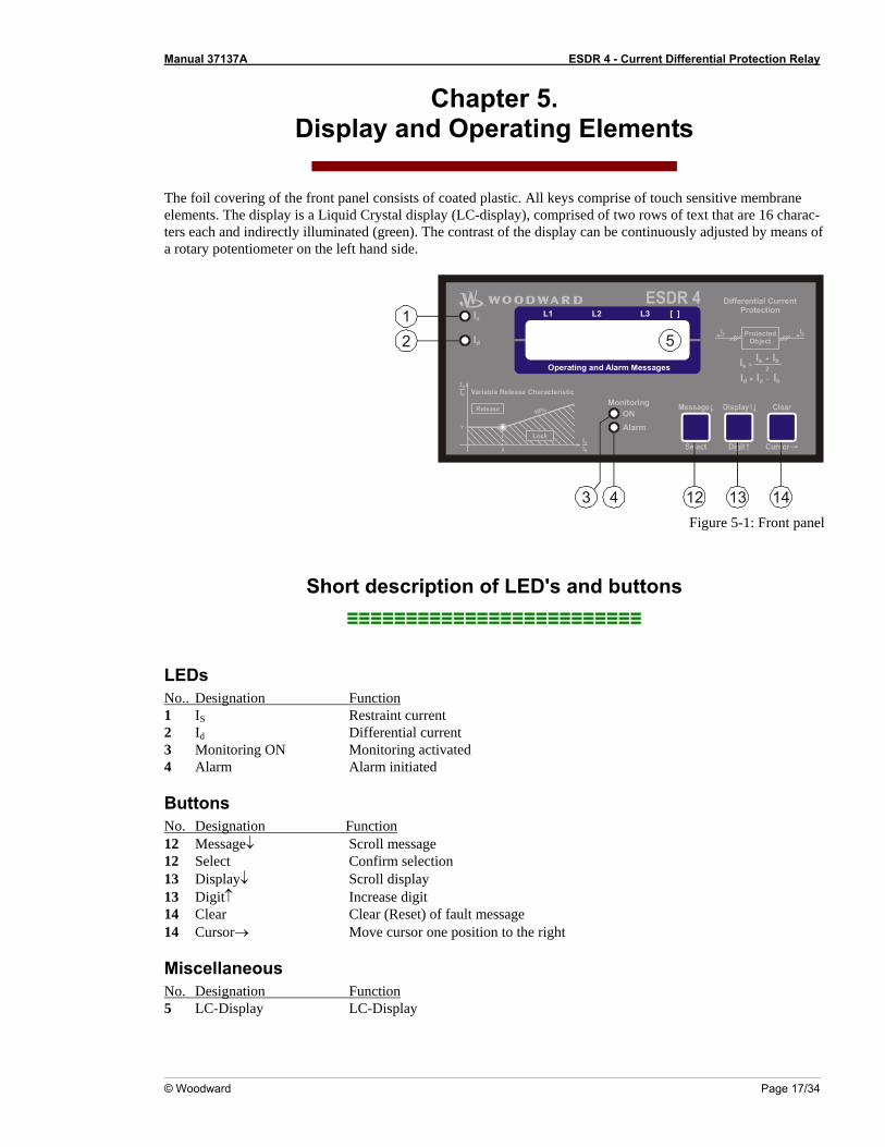
The foil covering of the front panel consists of coated plastic. All keys comprise of touch sensitive membrane elements. The display is a Liquid Crystal display (LC-display), comprised of two rows of text that are 16 charac-ters each and indirectly illuminated (green). The contrast of the display can be continuously adjusted by means of a rotary potentiometer on the left hand side.
Monitoring
Differential CurrentProtection
ONAlarm
Is Ia Ib+2=
Ia IbId =
ProtectedObject
Ia Ib
[ ]
Operating and Alarm Messages
L1 L2 L3
Release
Variable Release Characteristic
X
Y
10%
Id
NI
Is
NI
Lock
Is
Id
12
4 12 13 14
5
3 Figure 5-1: Front panel
Short description of LED's and buttons ≡≡≡≡≡≡≡≡≡≡≡≡≡≡≡≡≡≡≡≡≡≡≡≡≡
LEDs No.. Designation Function 1 IS Restraint current 2 Id Differential current 3 Monitoring ON Monitoring activated 4 Alarm Alarm initiated
Buttons No. Designation Function 12 Message↓ Scroll message 12 Select Confirm selection 13 Display↓ Scroll display 13 Digit↑ Increase digit 14 Clear Clear (Reset) of fault message 14 Cursor→ Move cursor one position to the right
Miscellaneous No. Designation Function 5 LC-Display LC-Display
Manual 37137A ESDR 4 - Current Differential Protection Relay
Page 18/34 © Woodward
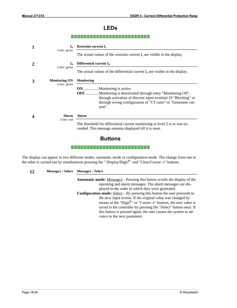
LEDs ≡≡≡≡≡≡≡≡≡≡≡≡≡≡≡≡≡≡≡≡≡≡≡≡≡
1 IS
Color: green Restraint current Is
The actual values of the restraint current Is are visible in the display
2 Id Color: green
Differential current Id
The actual values of the differential current Id are visible in the display.
3 Monitoring ON Color: green
Monitoring
ON ................Monitoring is active. OFF ..............Monitoring is deactivated through entry "Monitoring Off",
through activation of discrete input terminal 19 "Blocking" or through wrong configuration of "CT-ratio" or "Generator cur-rent".
4 Alarm
Color: red Alarm
The threshold for differential current monitoring in level 2 is or was ex-ceeded. This message remains displayed till it is reset.
Buttons ≡≡≡≡≡≡≡≡≡≡≡≡≡≡≡≡≡≡≡≡≡≡≡≡≡
The display can appear in two different modes: automatic mode or configuration mode. The change from one to the other is carried out by simultaneous pressing the " Display/Digit↑" and "Clear/Cursor→" buttons.
12 Message↓ / Select
Message↓ / Select
Automatic mode: Message↓ - Pressing this button scrolls the display of the operating and alarm messages. The alarm messages are dis-played in the order in which they were generated.
Configuration mode: Select – By pressing this button the user proceeds to the next input screen. If the original value was changed by means of the "Digit↑" or "Cursor→" buttons, the new value is saved to the controller by pressing the "Select" button once. If this button is pressed again, the user causes the system to ad-vance to the next parameter.
Manual 37137A ESDR 4 - Current Differential Protection Relay
© Woodward Page 19/34
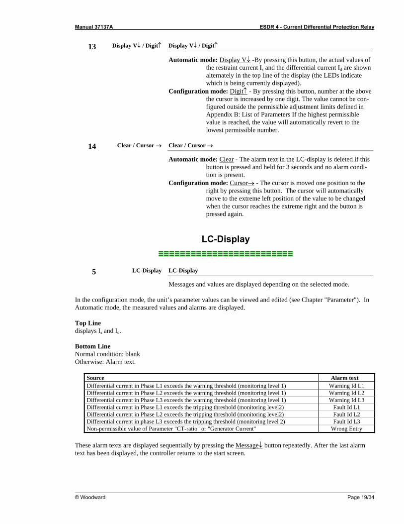
13 Display V↓ / Digit↑
Display V↓ / Digit↑
Automatic mode: Display V↓ -By pressing this button, the actual values of the restraint current Is and the differential current Id are shown alternately in the top line of the display (the LEDs indicate which is being currently displayed).
Configuration mode: Digit↑ - By pressing this button, number at the above the cursor is increased by one digit. The value cannot be con-figured outside the permissible adjustment limits defined in Appendix B: List of Parameters If the highest permissible value is reached, the value will automatically revert to the lowest permissible number.
14 Clear / Cursor →
Clear / Cursor →
Automatic mode: Clear - The alarm text in the LC-display is deleted if this button is pressed and held for 3 seconds and no alarm condi-tion is present.
Configuration mode: Cursor→ - The cursor is moved one position to the right by pressing this button. The cursor will automatically move to the extreme left position of the value to be changed when the cursor reaches the extreme right and the button is pressed again.
LC-Display ≡≡≡≡≡≡≡≡≡≡≡≡≡≡≡≡≡≡≡≡≡≡≡≡≡
5 LC-Display LC-Display
Messages and values are displayed depending on the selected mode. In the configuration mode, the unit’s parameter values can be viewed and edited (see Chapter "Parameter"). In Automatic mode, the measured values and alarms are displayed. Top Line displays Is and Id. Bottom Line Normal condition: blank Otherwise: Alarm text.
Source Alarm text Differential current in Phase L1 exceeds the warning threshold (monitoring level 1) Warning Id L1 Differential current in Phase L2 exceeds the warning threshold (monitoring level 1) Warning Id L2 Differential current in Phase L3 exceeds the warning threshold (monitoring level 1) Warning Id L3 Differential current in Phase L1 exceeds the tripping threshold (monitoring level2) Fault Id L1 Differential current in Phase L2 exceeds the tripping threshold (monitoring level2) Fault Id L2 Differential current in phase L3 exceeds the tripping threshold (monitoring level 2) Fault Id L3 Non-permissible value of Parameter "CT-ratio" or "Generator Current" Wrong Entry
These alarm texts are displayed sequentially by pressing the Message↓ button repeatedly. After the last alarm text has been displayed, the controller returns to the start screen.
Manual 37137A ESDR 4 - Current Differential Protection Relay
Page 20/34 © Woodward
Chapter 6. Configuration
Introduction ≡≡≡≡≡≡≡≡≡≡≡≡≡≡≡≡≡≡≡≡≡≡≡≡≡
When in configuration mode (simultaneous pressing of "Digit↑" and "Cursor→"), the configuration screen can be advanced by pressing the "Select" button. Should there be no entry, parameter change or other action for 60 seconds, the unit will automatically revert into Automatic mode. During the configuration mode, the monitoring function is still active. This means inevitably, that while adjusting parameters during operation, it is possible to cause a tripping of the relay.
Manual 37137A ESDR 4 - Current Differential Protection Relay
© Woodward Page 21/34
Basic data ≡≡≡≡≡≡≡≡≡≡≡≡≡≡≡≡≡≡≡≡≡≡≡≡≡
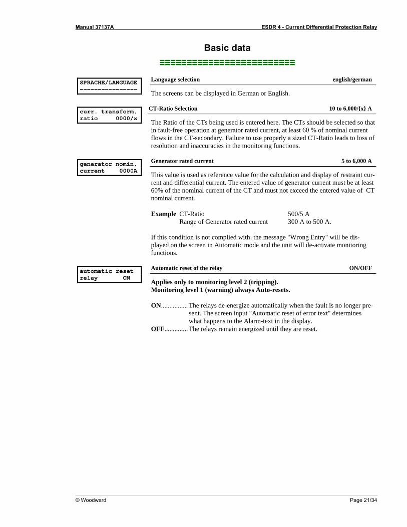
SPRACHE/LANGUAGE ----------------
Language selection english/german
The screens can be displayed in German or English. curr. transform. ratio 0000/x
CT-Ratio Selection 10 to 6,000/x A
The Ratio of the CTs being used is entered here. The CTs should be selected so that in fault-free operation at generator rated current, at least 60 % of nominal current flows in the CT-secondary. Failure to use properly a sized CT-Ratio leads to loss of resolution and inaccuracies in the monitoring functions.
generator nomin. current 0000A
Generator rated current 5 to 6,000 A
This value is used as reference value for the calculation and display of restraint cur-rent and differential current. The entered value of generator current must be at least 60% of the nominal current of the CT and must not exceed the entered value of CT nominal current. Example CT-Ratio 500/5 A Range of Generator rated current 300 A to 500 A. If this condition is not complied with, the message "Wrong Entry" will be dis-played on the screen in Automatic mode and the unit will de-activate monitoring functions.
automatic reset relay ON
Automatic reset of the relay ON/OFF
Applies only to monitoring level 2 (tripping). Monitoring level 1 (warning) always Auto-resets. ON................ The relays de-energize automatically when the fault is no longer pre-
sent. The screen input "Automatic reset of error text" determines what happens to the Alarm-text in the display.
OFF.............. The relays remain energized until they are reset.
Manual 37137A ESDR 4 - Current Differential Protection Relay
Page 22/34 © Woodward
Protection ≡≡≡≡≡≡≡≡≡≡≡≡≡≡≡≡≡≡≡≡≡≡≡≡≡
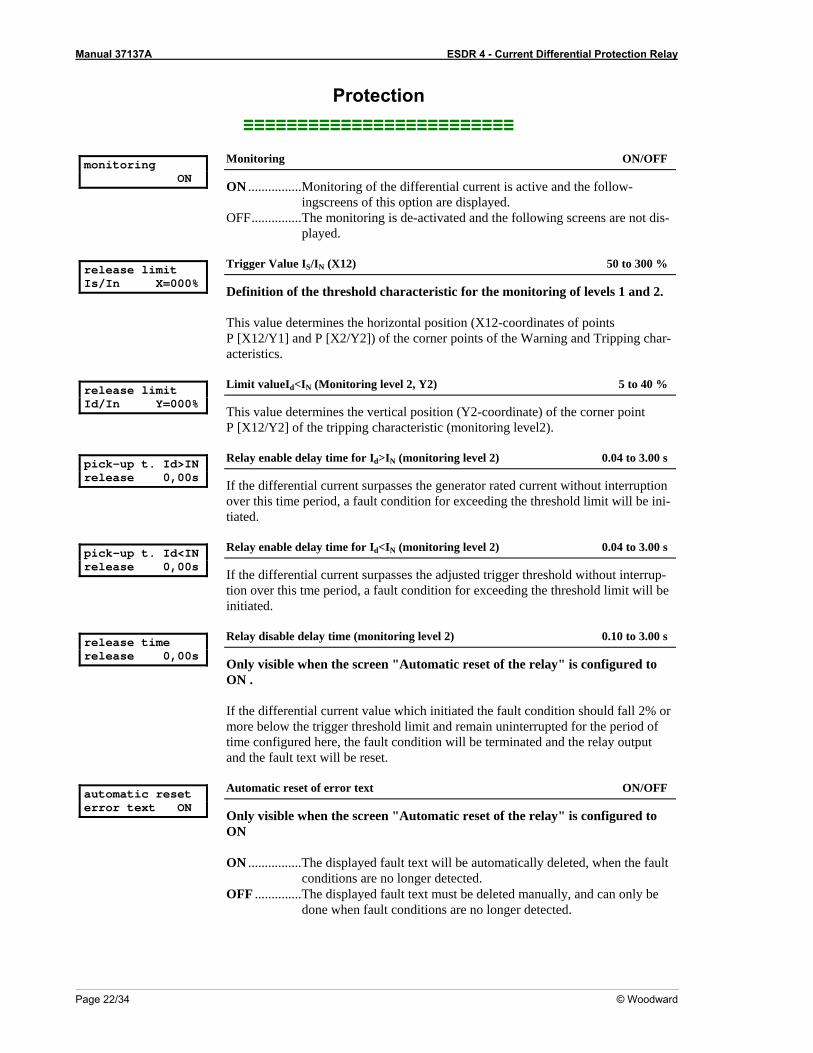
monitoring ON
Monitoring ON/OFF
ON ................Monitoring of the differential current is active and the follow-ingscreens of this option are displayed.
OFF...............The monitoring is de-activated and the following screens are not dis-played.
release limit Is/In X=000%
Trigger Value IS/IN (X12) 50 to 300 %
Definition of the threshold characteristic for the monitoring of levels 1 and 2. This value determines the horizontal position (X12-coordinates of points P [X12/Y1] and P [X2/Y2]) of the corner points of the Warning and Tripping char-acteristics.
release limit Id/In Y=000%
Limit valueId<IN (Monitoring level 2, Y2) 5 to 40 %
This value determines the vertical position (Y2-coordinate) of the corner point P [X12/Y2] of the tripping characteristic (monitoring level2).
pick-up t. Id>IN release 0,00s
Relay enable delay time for Id>IN (monitoring level 2) 0.04 to 3.00 s
If the differential current surpasses the generator rated current without interruption over this time period, a fault condition for exceeding the threshold limit will be ini-tiated.
pick-up t. Id<IN release 0,00s
Relay enable delay time for Id<IN (monitoring level 2) 0.04 to 3.00 s
If the differential current surpasses the adjusted trigger threshold without interrup-tion over this tme period, a fault condition for exceeding the threshold limit will be initiated.
release time release 0,00s
Relay disable delay time (monitoring level 2) 0.10 to 3.00 s
Only visible when the screen "Automatic reset of the relay" is configured to ON . If the differential current value which initiated the fault condition should fall 2% or more below the trigger threshold limit and remain uninterrupted for the period of time configured here, the fault condition will be terminated and the relay output and the fault text will be reset.
automatic reset error text ON
Automatic reset of error text ON/OFF
Only visible when the screen "Automatic reset of the relay" is configured to ON ON ................The displayed fault text will be automatically deleted, when the fault
conditions are no longer detected. OFF ..............The displayed fault text must be deleted manually, and can only be
done when fault conditions are no longer detected.
Manual 37137A ESDR 4 - Current Differential Protection Relay
© Woodward Page 23/34
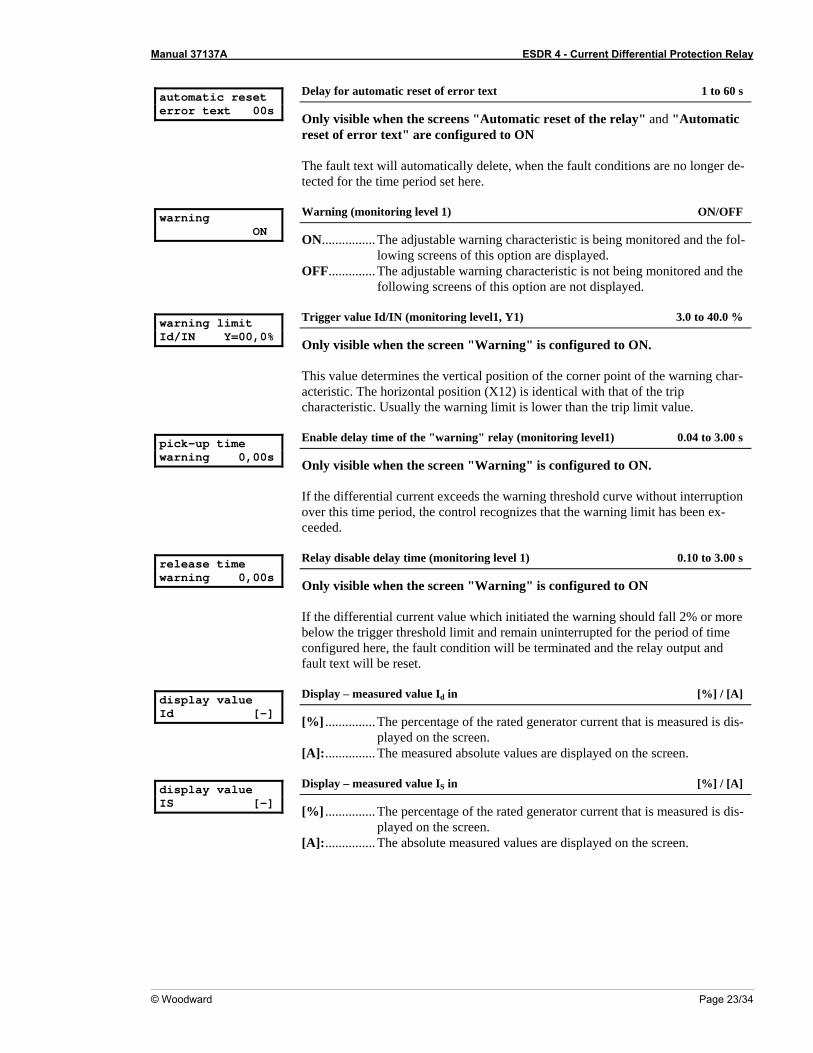
automatic reset error text 00s
Delay for automatic reset of error text 1 to 60 s
Only visible when the screens "Automatic reset of the relay" and "Automatic reset of error text" are configured to ON The fault text will automatically delete, when the fault conditions are no longer de-tected for the time period set here.
warning ON
Warning (monitoring level 1) ON/OFF
ON................ The adjustable warning characteristic is being monitored and the fol-lowing screens of this option are displayed.
OFF.............. The adjustable warning characteristic is not being monitored and the following screens of this option are not displayed.
warning limit Id/IN Y=00,0%
Trigger value Id/IN (monitoring level1, Y1) 3.0 to 40.0 %
Only visible when the screen "Warning" is configured to ON. This value determines the vertical position of the corner point of the warning char-acteristic. The horizontal position (X12) is identical with that of the trip characteristic. Usually the warning limit is lower than the trip limit value.
pick-up time warning 0,00s
Enable delay time of the "warning" relay (monitoring level1) 0.04 to 3.00 s
Only visible when the screen "Warning" is configured to ON. If the differential current exceeds the warning threshold curve without interruption over this time period, the control recognizes that the warning limit has been ex-ceeded.
release time warning 0,00s
Relay disable delay time (monitoring level 1) 0.10 to 3.00 s
Only visible when the screen "Warning" is configured to ON If the differential current value which initiated the warning should fall 2% or more below the trigger threshold limit and remain uninterrupted for the period of time configured here, the fault condition will be terminated and the relay output and fault text will be reset.
display value Id [-]
Display – measured value Id in [%] / [A]
[%] ............... The percentage of the rated generator current that is measured is dis-played on the screen.
[A]:............... The measured absolute values are displayed on the screen. display value IS [-]
Display – measured value IS in [%] / [A]
[%] ............... The percentage of the rated generator current that is measured is dis-played on the screen.
[A]:............... The absolute measured values are displayed on the screen.
Manual 37137A ESDR 4 - Current Differential Protection Relay
Page 24/34 © Woodward
Chapter 7. Commissioning
DANGER - HIGH VOLTAGE When commissioning the control, please observe all safety rules that apply to the handling of live equipment. Ensure that you know how to provide first aid in the event of an uncontrolled release of en-ergy and that you know where the first aid kit and the nearest telephone are. Never touch any live com-ponents of the system or on the back of the system:
L I F E T H R E A T E N I N G
CAUTION Only a qualified technician may commission unit. The "EMERGENCY-STOP" function must be opera-tional prior to commissioning of the system, and must not depend on the unit for its operation.
CAUTION Prior to commissioning ensure that all measuring devices are connected in correct phase sequence. The connect command for the unit circuit breaker must be disconnected at the unit circuit breaker. The field rotation must be monitored for proper rotation. Any absence of or incorrect connection of voltage measuring devices or other signals may lead to malfunctions and damage the unit, the engine, and/or components connected to the unit!
Prerequisite Connect the unit according to the wiring diagram on Page 8. Pre-adjustments In order to put the unit into operation, you must
1. • connect the auxiliary 24Vdc power supply (terminals 13/14), 2. • activate the configuration mode (press "Digit↑" and "Cursor→"), 3. • set all parameters according to the Chapter "Configuration" 4. • activate the Automatic mode (press "Digit↑" and "Cursor→").
Commissioning using primary values During commissioning, a configuration should be found which allows the finest possible adjustment of the cur-rents. If the current is to flow through a short-circuiting bridge, the automatic voltage regulator should be turned off and the generator excitation adjusted manually. Testing for correct connection The excitation should be set so that the generator is loaded to approx. 20% rated current. If the connections are correct, the displayed differential current should be about zero. The displayed restraint current should be checked using an external measuring device. Record all measured values. If the displayed restraint currents are not approximately equal or very high differential currents are being dis-played, then the system should be turned off and the configuration of the CTs should be checked.
Manual 37137A ESDR 4 - Current Differential Protection Relay
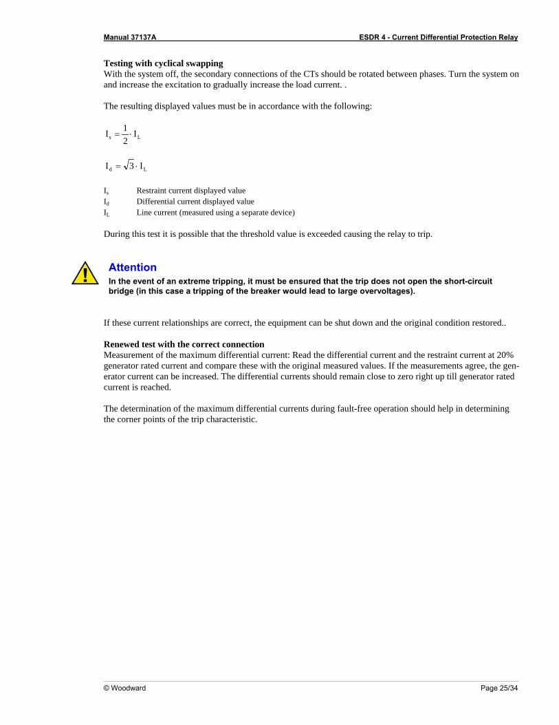
Testing with cyclical swapping With the system off, the secondary connections of the CTs should be rotated between phases. Turn the system on and increase the excitation to gradually increase the load current. . The resulting displayed values must be in accordance with the following:
Ls I21I ⋅=
Ld I3I ⋅= Is Restraint current displayed value Id Differential current displayed value IL Line current (measured using a separate device) During this test it is possible that the threshold value is exceeded causing the relay to trip.
Attention In the event of an extreme tripping, it must be ensured that the trip does not open the short-circuit bridge (in this case a tripping of the breaker would lead to large overvoltages).
If these current relationships are correct, the equipment can be shut down and the original condition restored.. Renewed test with the correct connection Measurement of the maximum differential current: Read the differential current and the restraint current at 20% generator rated current and compare these with the original measured values. If the measurements agree, the gen-erator current can be increased. The differential currents should remain close to zero right up till generator rated current is reached. The determination of the maximum differential currents during fault-free operation should help in determining the corner points of the trip characteristic.
© Woodward Page 25/34
Manual 37137A ESDR 4 - Current Differential Protection Relay
Page 26/34 © Woodward
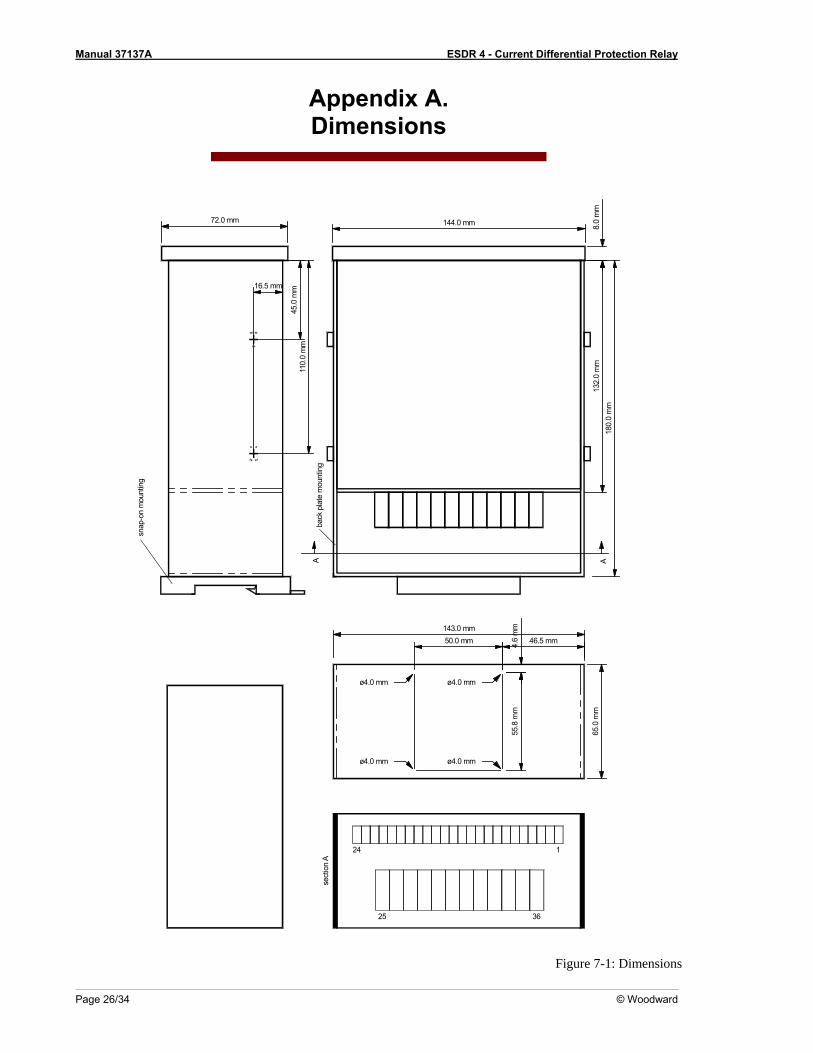
Appendix A. Dimensions
143.0 mm50.0 mm
1
36
65.0
mm
55.8
mm
ø4.0 mm
46.5 mm4.6
mm
ø4.0 mm
24
sect
ion
A
25
ø4.0 mm
ø4.0 mm
144.0 mm
180.
0 m
m13
2.0
mm
A8.
0 m
m
110.
0 m
m45
.0 m
m16.5 mm
back
pla
te m
ount
ing
A
snap
-on
mou
ntin
g
72.0 mm
Figure 7-1: Dimensions
Manual 37137A ESDR 4 - Current Differential Protection Relay
© Woodward Page 27/34
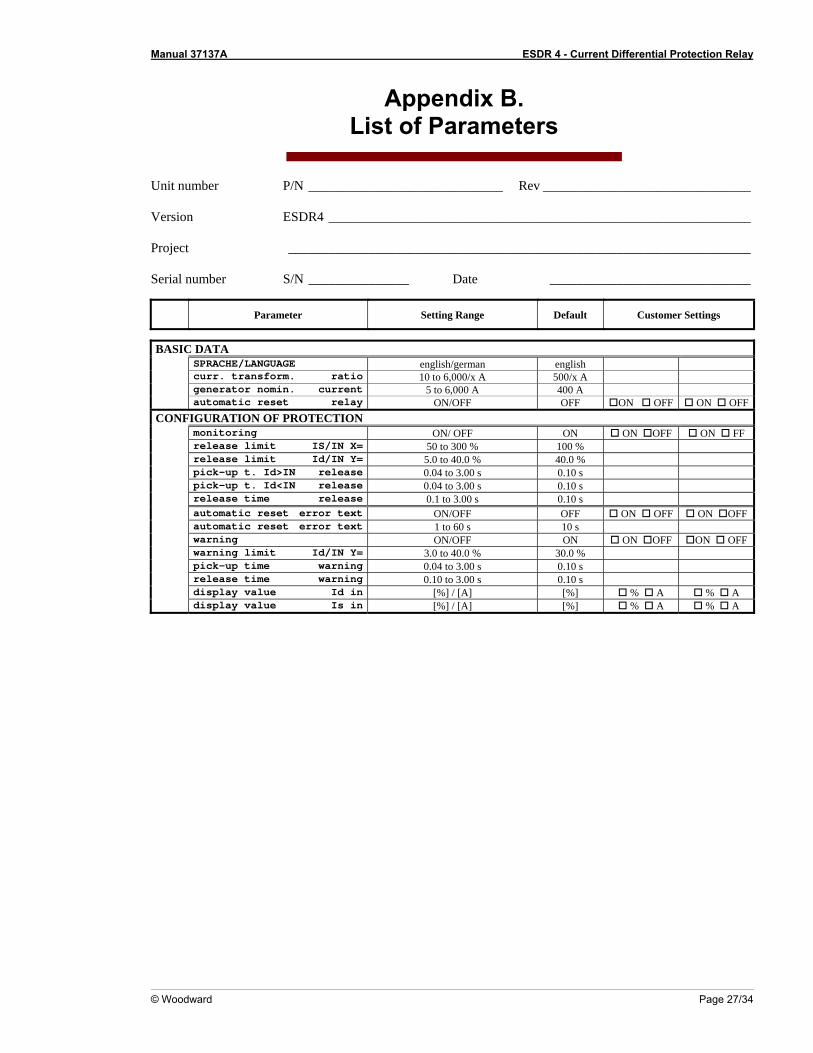
Appendix B. List of Parameters
Unit number P/N _____________________________ Rev _______________________________ Version ESDR4 _______________________________________________________________ Project _____________________________________________________________________ Serial number S/N _______________ Date ______________________________
Parameter Setting Range Default Customer Settings
BASIC DATA SPRACHE/LANGUAGE english/german english curr. transform. ratio 10 to 6,000/x A 500/x A generator nomin. current 5 to 6,000 A 400 A automatic reset relay ON/OFF OFF ON OFF ON OFF
CONFIGURATION OF PROTECTION monitoring ON/ OFF ON ON OFF ON FF release limit IS/IN X= 50 to 300 % 100 % release limit Id/IN Y= 5.0 to 40.0 % 40.0 % pick-up t. Id>IN release 0.04 to 3.00 s 0.10 s pick-up t. Id<IN release 0.04 to 3.00 s 0.10 s release time release 0.1 to 3.00 s 0.10 s automatic reset error text ON/OFF OFF ON OFF ON OFF automatic reset error text 1 to 60 s 10 s warning ON/OFF ON ON OFF ON OFF warning limit Id/IN Y= 3.0 to 40.0 % 30.0 % pick-up time warning 0.04 to 3.00 s 0.10 s release time warning 0.10 to 3.00 s 0.10 s display value Id in [%] / [A] [%] % A % A display value Is in [%] / [A] [%] % A % A
Manual 37137A ESDR 4 - Current Differential Protection Relay
Page 28/34 © Woodward
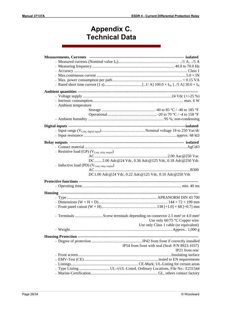
Appendix C. Technical Data
Measurements, Currents ------------------------------------------------------------------------ isolated - Measured currents (Nominal value IN)............................................................. ../1 A, ../5 A - Measuring frequency ................................................................................... 40.0 to 70.0 Hz - Accuracy ................................................................................................................... Class 1 - Max.continuous current ...........................................................................................5.0 × IN - Max. power consumption per path....................................................................... < 0.15 VA - Rated short time current (1 s)...................................... [..1/ A] 100.0 × IN, [../5 A] 30.0 × IN
Ambient quantities -------------------------------------------------------------------------------------------- - Voltage supply ..........................................................................................24 Vdc (+/-25 %) - Intrinsic consumption............................................................................................ max. 6 W - Ambient temperature Storage ...................................................... -40 to 85 °C / -40 to 185 °F Operational.................................................. -20 to 70 °C / -4 to 158 °F - Ambient humidity ............................................................................. 95 %, non-condensing
Digital inputs -----------------------------------------------------------------------------------------isolated - Input range (VCont, digital input)............................................ Nominal voltage 18 to 250 Vac/dc - Input resistance ..............................................................................................approx. 68 kΩ
Relay outputs --------------------------------------------------------------------------------------- isolated - Contact material ........................................................................................................AgCdO - Resistive load (GP) (VCont, relay output) AC..........................................................................2.00 Aac@250 Vac DC....... 2.00 Adc@24 Vdc, 0.36 Adc@125 Vdc, 0.18 Adc@250 Vdc - Inductive load (PD) (VCont, relay output) AC.................................................................................................B300 DC 1.00 Adc@24 Vdc, 0.22 Adc@125 Vdc, 0.10 Adc@250 Vdc
Protective functions ------------------------------------------------------------------------------------------- - Operating time..................................................................................................... min. 40 ms
Housing --------------------------------------------------------------------------------------------------------- - Type ........................................................................................... APRANORM DIN 43 700 - Dimensions (W × H × D)...................................................................... 144 × 72 × 199 mm - Front panel cutout (W × H)........................................................138 [+1.0] × 68 [+0.7] mm - Terminals ............................ Screw terminals depending on connector 2.5 mm² or 4.0 mm²
Use only 60/75 °C Copper wire Use only Class 1 cable (or equivalent)
- Weight........................................................................................................Approx.. 1,000 g
Housing Protection -------------------------------------------------------------------------------------------- - Degree of protection ................................................... IP42 from front if correctly installed
IP54 from front with seal (Seal: P/N 8923-1037) IP21 from rear
- Front screen...............................................................................................Insulating surface - EMV-Test (CE)............................................................................tested to EN requirements - Listings.................................................................... CE-Mark; UL-Listing for certain areas - Type Listing ............................... UL-/cUL-Listed, Ordinary Locations, File No.: E231544 - Marine-Certification.................................................................... GL, others contact factory
Manual 37137A ESDR 4 - Current Differential Protection Relay
© Woodward Page 29/34
Appendix D. Service Options
Product service options ≡≡≡≡≡≡≡≡≡≡≡≡≡≡≡≡≡≡≡≡≡≡≡≡≡
The following factory options are available for servicing Woodward equipment, based on the standard Wood-ward Product and Service Warranty (5-01-1205) that is in effect at the time the product is purchased from Woodward or the service is performed. If you are experiencing problems with installation or unsatisfactory per-formance of an installed system, the following options are available: • Consult the troubleshooting guide in the manual. • Contact Woodward technical assistance (see "How to Contact Woodward" later in this chapter) and discuss
your problem. In most cases, your problem can be resolved over the phone. If not, you can select which course of action you wish to pursue based on the available services listed in this section.
Returning equipment for repair ≡≡≡≡≡≡≡≡≡≡≡≡≡≡≡≡≡≡≡≡≡≡≡≡≡
If a control (or any part of an electronic control) is to be returned to Woodward for repair, please contact Wood-ward in advance to obtain a Return Authorization Number. When shipping the unit(s), attach a tag with the fol-lowing information: • name and location where the control is installed • name and phone number of contact person • complete Woodward part numbers (P/N) and serial number (S/N) • description of the problem • instructions describing the desired type of repair
CAUTION To prevent damage to electronic components caused by improper handling, read and observe the pre-cautions in Woodward manual 82715, Guide for Handling and Protection of Electronic Controls, Printed Circuit Boards, and Modules.
Manual 37137A ESDR 4 - Current Differential Protection Relay
Page 30/34 © Woodward
Packing a control Use the following materials when returning a complete control: • protective caps on any connectors • antistatic protective bags on all electronic modules • packing materials that will not damage the surface of the unit • at least 100 mm (4 inches) of tightly packed, industry-approved packing material • a packing carton with double walls • a strong tape around the outside of the carton for increased strength
Return authorization number RAN When returning equipment to Woodward, please telephone and ask for the Customer Service Department in Stuttgart [+49 (0) 711-789 54-0]. They will help expedite the processing of your order through our distributors or local service facility. To expedite the repair process, contact Woodward in advance to obtain a Return Authoriza-tion Number, and arrange for issue of a purchase order for the unit(s) to be repaired. No work can be started until a purchase order is received.
NOTE We highly recommend that you make arrangement in advance for return shipments. Contact a Woodward customer service representative at +49 (0) 711-789 54-0 for instructions and for a Re-turn Authorization Number.
Replacement parts ≡≡≡≡≡≡≡≡≡≡≡≡≡≡≡≡≡≡≡≡≡≡≡≡≡
When ordering replacement parts for controls, include the following information: • the part numbers P/N (XXXX-XXX) that is on the enclosure nameplate • the unit serial number S/N, which is also on the nameplate
Manual 37137A ESDR 4 - Current Differential Protection Relay
© Woodward Page 31/34
How to contact Woodward ≡≡≡≡≡≡≡≡≡≡≡≡≡≡≡≡≡≡≡≡≡≡≡≡≡
Please contact following address if you have questions or if you want to send a product for repair: Woodward Governor Company Leonhard-Reglerbau GmbH Handwerkstrasse 29 70565 Stuttgart - Germany Phone: +49 (0) 711-789 54-0 (8:00 - 16:30 German time) Fax: +49 (0) 711-789 54-100 eMail: [email protected] For assistance outside Germany, call one of the following international Woodward facilities to obtain the address and phone number of the facility nearest your location where you will be able to get information and service. Facility Phone number USA +1 (970) 482 5811 India +91 (129) 230 7111 Brazil +55 (19) 3708 4800 Japan +81 (476) 93 4661 The Netherlands +31 (23) 566 1111 You can also contact the Woodward Customer Service Department or consult our worldwide directory on Woodward’s website (www.woodward.com) for the name of your nearest Woodward distributor or service fa-cility. [For worldwide directory information, go to www.woodward.com/ic/locations.]
Manual 37137A ESDR 4 - Current Differential Protection Relay
Page 32/34 © Woodward
Engineering services ≡≡≡≡≡≡≡≡≡≡≡≡≡≡≡≡≡≡≡≡≡≡≡≡≡
Woodward Industrial Controls Engineering Services offers the following after-sales support for Woodward prod-ucts. For these services, you can contact us by telephone, by e-mail, or through the Woodward website. • Technical support • Product training • Field service during commissioning Technical Support is available through our many worldwide locations, through our authorized distributors, or through GE Global Controls Services, depending on the product. This service can assist you with technical ques-tions or problem solving during normal business hours. Emergency assistance is also available during non-business hours by phoning our toll-free number and stating the urgency of your problem. For technical engineer-ing support, please contact us via our toll-free or local phone numbers, e-mail us, or use our website and refer-ence technical support. Product Training is available on-site from several of our worldwide facilities, at your location, or from GE Global Controls Services, depending on the product. This training, conducted by experienced personnel, will as-sure that you will be able to maintain system reliability and availability. For information concerning training, please contact us via our toll-free or local phone numbers, e-mail us, or use our website and reference customer training. Field Service engineering on-site support is available, depending on the product and location, from our facility in Colorado, or from one of many worldwide Woodward offices or authorized distributors. Field engineers are experienced on both Woodward products as well as on much of the non-Woodward equipment with which our products interface. For field service engineering assistance, please contact us via our toll-free or local phone numbers, e-mail us, or use our website and reference field service.

Manual 37137A ESDR 4 - Current Differential Protection Relay
© Woodward Page 33/34
Technical assistance ≡≡≡≡≡≡≡≡≡≡≡≡≡≡≡≡≡≡≡≡≡≡≡≡≡
If you need to telephone for technical assistance, you will need to provide the following information. Please write it down here before phoning: Contact Your company ___________________________________________________ Your name ______________________________________________________ Phone number ____________________________________________________ Fax number ______________________________________________________ Control (see name plate) Unit no. and revision: P/N: ___________________ REV: ____________ Unit type ESDR4 ____________________________________ Serial number S/N _______________________________________ Description of your problem _______________________________________________________________
_______________________________________________________________
_______________________________________________________________
_______________________________________________________________
_______________________________________________________________
_______________________________________________________________
Please be sure you have a list of all parameters available.

We appreciate your comments about the content of our publications. Please send comments to: [email protected]
Please include the manual number from the front cover of this publication.
Woodward Governor Company Leonhard-Reglerbau GmbH
Handwerkstrasse 29 - 70565 Stuttgart - Germany Phone +49 (0) 711-789 54-0 • Fax +49 (0) 711-789 54-100
Homepage
http://www.woodward.com/smart-power
Woodward has company-owned plants, subsidiaries, and branches, as well as authorized distributors and other authorized service and sales facilities throughout the world.
Complete address/phone/fax/e-mail information
for all locations is available on our website (www.woodward.com).
04/10/S