digi-bee - pc control. logic-lab application software 3.1 overview digi-bee is designed to allow the...
TRANSCRIPT

DIGI-BEE Automation Adaptor
Version 3
Installation and Users Manual (Including Logic-Lab Software)
Available exclusively from
PC Control Ltd.
www.pc-control.co.uk
2009-2018 Copyright PC Control Ltd.

Contents
1 Introduction
2 Hardware Installation
3 Logic-Lab Application Software
3.1 Overview
3.2 Logic-Lab Main Screen
3.3 Save and Restore Configurations
4 Connecting to Digi-Bee
5 Connector Pinouts
6 Writing Your Own Software to Use Digi-Bee
6.1 Using Digi-Bee with visual Basic
6.2 Using Digi-Bee with visual C++
7 Minimum PC System Requirements
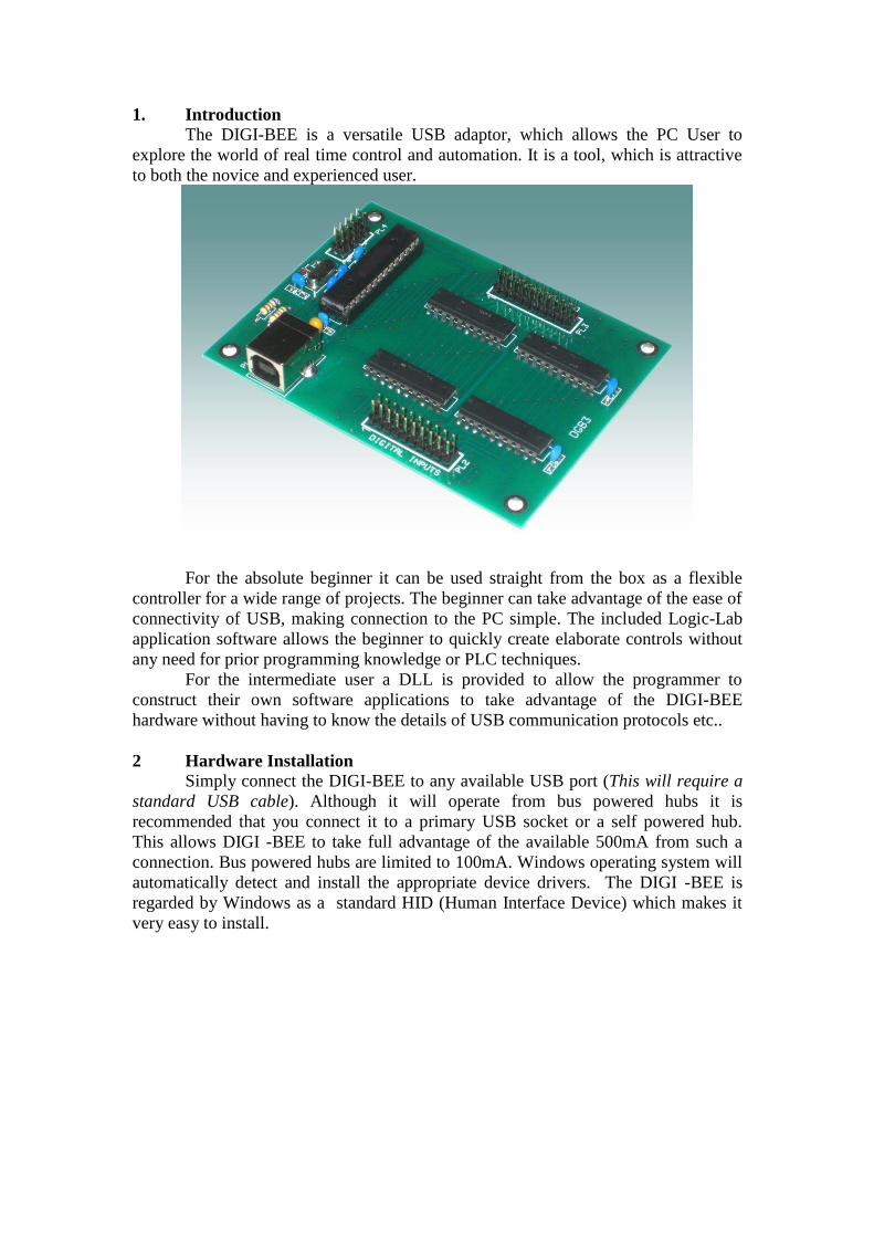
1. Introduction
The DIGI-BEE is a versatile USB adaptor, which allows the PC User to
explore the world of real time control and automation. It is a tool, which is attractive
to both the novice and experienced user.
For the absolute beginner it can be used straight from the box as a flexible
controller for a wide range of projects. The beginner can take advantage of the ease of
connectivity of USB, making connection to the PC simple. The included Logic-Lab
application software allows the beginner to quickly create elaborate controls without
any need for prior programming knowledge or PLC techniques.
For the intermediate user a DLL is provided to allow the programmer to
construct their own software applications to take advantage of the DIGI-BEE
hardware without having to know the details of USB communication protocols etc..
2 Hardware Installation
Simply connect the DIGI-BEE to any available USB port (This will require a
standard USB cable). Although it will operate from bus powered hubs it is
recommended that you connect it to a primary USB socket or a self powered hub.
This allows DIGI -BEE to take full advantage of the available 500mA from such a
connection. Bus powered hubs are limited to 100mA. Windows operating system will
automatically detect and install the appropriate device drivers. The DIGI -BEE is
regarded by Windows as a standard HID (Human Interface Device) which makes it
very easy to install.

3. Logic-Lab Application Software
3.1 Overview
Digi-Bee is designed to allow the PC user to implement a real world control
system based on reading digital input signals and setting digital output signals.
However, any control system needs logic to determine which outputs to turn on or off
based on the current state of the inputs. This is where Logic-Lab is used. It forms the
logical bridge between inputs and outputs connected to the Digi-Bee. Operating in a
manner similar to a PLC system it repeatedly carries out the following three
functions…
Read all inputs – Calculate new outputs – Set all outputs
Logic–lab allows the second function “calculate new outputs” to be specified
in terms of traditional logic functions which is described more fully below. It also
allows the speed at which the above control loop is run to be specified. This can be
important since operating too slowly can miss transitions on some inputs and create
too great a time lag to setting the corresponding outputs. Similarly operating too
quickly can unnecessarily slow down the operation of the PC.
3.2 Logic-Lab Main Screen
Lets look at the main areas of the LogicLab screen and what they do. The
“Input/Output mimic” area shows the current status of the actual inputs and outputs to
the Digi-Bee.
When an indicator lamp is red the logic input is at ‘1’ (i.e. high or +5v) and
when it is grey it is at logic ‘0’ (i.e. low or 0v). There is a separate lamp for each of
the 16 inputs and each of 16 outputs. There are also 16 lamps for the status of a group
of internal logic values labelled A-P. The use of this internal logic will become
apparent as we examine the other logic functions below, but they are also represented
by red for ‘1’ and grey for ‘0’. At the top of the mimic area there are a row of 16 tick
boxes labelled “Test Inputs”. These allow you to “Test” your logic without actually
supplying signals to the DigiBee inputs. When in “manual mode” (discussed later)
ticking the box represents the corresponding input being on (i.e. logic ‘1’, +5v).
The operation area contains controls that allow you to specify how the system
will actually run. Pressing the “RUN” button will cause continuous execution of the
functions described above (i.e. Read all inputs – Calculate new outputs – Set all
outputs). Pressing “STOP” halts this process. The time interval at which this loop is
executed can be specified using the “Update Interval” selection box. This will allow
time intervals from 50ms to 5 seconds to be selected. This should be chosen to reflect
the nature of the changes of the inputs and the desired response time of the outputs to
these changes. Remember that this is intended for real world control and not much
can happen in 50ms when considering activation of solenoids, switches and motors
etc.
The right hand side of the operation area is devoted to testing and mimic
display settings. The system can operate in two modes, namely “Manual” and
“Automatic”. In automatic mode the system will read the actual inputs from the Digi-
Bee and set the actual outputs on the Digi-Bee. In Manual mode the inputs will be
read from the current selection of tick boxes in the mimic area. Manual mode allows
you to test your logic without having to generate real signals into the Digi-Bee.
Pressing the “Test” button while in manual mode causes one execution of the loop…
Read all inputs – Calculate new outputs – Set all outputs. The “Mimic On” tick box
will cause all of the screen indicator lamps to follow the current state of the inputs and
outputs whether they are real world from the Digi-Bee or tick boxes in “Test” mode.
Although the “Mimic On” setting is generally left ‘on’ there are times when it is
advantageous to disable this facility. This would be when you are running in
automatic mode at , perhaps, the highest update rate and your PC is not the fastest on
the planet, or just running too many other programs at the same time. i.e. it reduces
the processing requirements of the PC to leave the mimic off.
The main area of the screen is dedicated to specifying the logical relationship
between inputs and outputs. It consists of 24 boolean logic equations. Each of these
equations can be configured to use any input, output or intermediate logic value with
a selectable logic function linking them. Please note that you do not need to specify
all 24 equations to use this system. You only specify as many as you need and leave
the rest blank.
For example: Equation 1 can be specified as…
Output1 = Input1 and Input2
If the system is then started by pressing the “RUN” button, output 1 will only
turn on when both input 1 AND input 2 are on. In a similar way the function “AND”
can be changed to “OR” or “NOT”. Note that when the function is “NOT” the
second element of the equation is ignored… for example
Output1 = Input1 NOT Input2
In this case whenever input 2 is ON , output 1 is OFF and vice versa. Input 1 is
ignored. It is good practice to set the first input element to blank in this situation just
to make the equation more readable i.e. it is better specified as…
Output1 = NOT Input2
Up to 24 equations of this type can be specified and all of them will be
“calculated” when the system is “Running”. There is no restriction on having just one
equation setting a given output. For example you could specify equation 1 as
Output1 = Input1 and Input2
and then have equation 7 as
Output1 = Input11 OR Input12
When it comes to calculation time both equations will be evaluated but the
later one will have precedence. i.e. the equations are calculated in their numerical
order (1-24) and the last equation to set a given output will be the one which is used.
Note that although the setting for an output may change between equations during the
calculation phase, this is not reflected in the actual outputs of the DigiBee. All
calculations (1-24) are completed before any outputs are set.
Although the above gives a very flexible method of determining outputs based
on inputs, it can be rather limiting in it’s extent. This is why we have intermediate
logic values A-P. These are in no way related to any real world input or output but
allow multiple levels of logic to be created between the actual inputs and outputs. For
example suppose you wanted to have output 1 turn on only when all four inputs 1,2,3
and 4 are on. This would be a 4 way “AND” function. Since our equations are only
designed for two elements we need to use the intermediate logic as follows….
1. LogicA = Input1 AND Input2
2. LogicB = Input3 AND Input4
3. Output1 = LogicA AND LogicB
The above three equations would provide the necessary 4 way “AND” function.
This technique can be extended to more complex designs involving any combination
of AND, OR and NOT over multiple levels. In constructing multiple level logic
designs always be aware of the order in which the equations are calculated (i.e. 1 to
24) ensuring that all “lower level” functions are calculated first.
While this degree of flexibility allows for a wide selection of control logic
scenarios , it is not, and is not meant to be, capable of every possible set of logic.
3.3 Save and Restore Configurations
Once you have your system logic equations specified, they may be stored for
later retrieval using the “Save” and “Restore” buttons. This follows conventional
windows techniques for naming files and should be familiar. The “Quick Save” and
“quick restore” is a useful convenience for those (like me) who often don’t want, or
need, to specify a file name every time you want to save a configuration before
closing the application. Pressing “Quick Save” simply saves the current configuration
to a file called “current” with “Quick Restore” retrieving the configuration from this
same file.

4. Connecting to Digi-Bee
Two 20 way headers are provided for making connections to the Digi-Bee.
PL2 has 16 digital inputs, two grounds (0v) and two +5v supplies. PL3 has 16 digital
outputs and 4 grounds (0v). Digi-Bee inputs and outputs are standard CMOS 5v
digital logic compatible. The devices on the DigiBee board to which both inputs and
outputs are connected are 74HC573 latches. It should be noted that the 5v supply
available on the input connector (PL2) pins 9 and 10 is derived from the raw USB
connector supply and should be treated with some care. It is intended to provide a
relatively small amount of current to be used, for example, in “pull up” functions for
attaching switches (as shown below).
It should not be used to power large electrical circuits. It is recommended to
keep current usage on this supply to below 100mA. If this supply is not needed on
your input connection then the jumper on the Digi-Bee (labelled “5v Link”) should be
removed as a safety precaution. This would then leave the pins 9 and 10 disconnected
from Digi-Bee internal circuitry and the USB 5v supply.
The external circuitry to which these inputs and outputs are connected is,
obviously, beyond the scope of this manual, but to assist in determining electrical
compatibility and suitability to application, the data sheet for the output devices on the
Digi-Bee is included on the installation disk. The input and output characteristics of
these devices such as current source/sink capacity(approx 25mA per connection),
switching speed etc.. etc.. are fully detailed in the data sheet. However, the following
guidelines may be useful as a set of tips for the beginner.
1. Always ensure you have a good 0v (ground) connection between the
Digi-Bee and your own electronics. This is why 2 pins have been
devoted to GND on the input connector (PL2) and 4 pins on the output
connector (PL3).
2. Make sure the current requirements of the devices you are
connecting to can be provided by the Digi-Bee 74HC573 output
devices.
3. A standard 20 way ribbon cable assembly with IDC sockets is the
recommended way of connecting to Digi-Bee. If you are connecting to
your own electronics board then why not fit an identical 20 way header
to your board allowing you to use one of the cheap and plentiful ribbon
cable assemblies available from most electronics stores.

4. If you need to switch inductive loads such as motors or solenoids
consider purchasing the “Bee-Driver” from www.pc-user.co.uk which
converts the Digi-Bee output connector (PL2) into 14 high voltage
switching outputs with voltage spike protection, or simply construct
your own using devices such as the ULN2003 transistor array driver
available from most electronics suppliers. With this type of conversion
it is then very easy to scale up the power handling potential of the
Digi-Bee to unlimited amounts using relays which can then be
“driven” directly.
5 Connector Pinouts
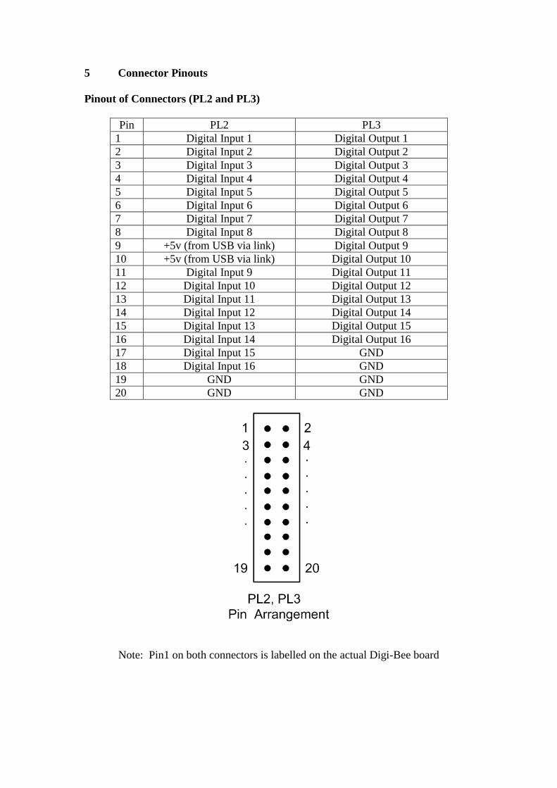
Pinout of Connectors (PL2 and PL3)
Pin PL2 PL3
1 Digital Input 1 Digital Output 1
2 Digital Input 2 Digital Output 2
3 Digital Input 3 Digital Output 3
4 Digital Input 4 Digital Output 4
5 Digital Input 5 Digital Output 5
6 Digital Input 6 Digital Output 6
7 Digital Input 7 Digital Output 7
8 Digital Input 8 Digital Output 8
9 +5v (from USB via link) Digital Output 9
10 +5v (from USB via link) Digital Output 10
11 Digital Input 9 Digital Output 11
12 Digital Input 10 Digital Output 12
13 Digital Input 11 Digital Output 13
14 Digital Input 12 Digital Output 14
15 Digital Input 13 Digital Output 15
16 Digital Input 14 Digital Output 16
17 Digital Input 15 GND
18 Digital Input 16 GND
19 GND GND
20 GND GND
Note: Pin1 on both connectors is labelled on the actual Digi-Bee board

6. Writing your own software for Digi-Bee
To use Digi-Bee straight from the box does not require any programming
other than entering your control logic details into Logic-Lab. However, if you prefer
to design you own software then the following information will be of use.
Provided with Digi-Bee is a DLL (dynamic link library) called “dgb.dll”. This
encapsulates the functions used by Logic-Lab in communicating with Digi-Bee across
the USB interface into three simple functions easily understood and used in custom
software. Although the DLL was written in ‘C’ it can be used (called) by programs
written in a number of popular languages, the most popular of which is BASIC
(Visual BASIC). Described below are the techniques to use the DLL in Visual Basic
and C++. If you program in another language please refer to your compiler manual on
the details of calling a C++ library function, which will be very similar to the
techniques described below.
6.1 Using DigiBee with Visual Basic.
Using Digi-Bee with your own programs written in visual basic is very simple.
At the head of your program, before using any of the Digi-Bee functions, you must
make the following declarations… Declare Function InitDgb Lib "dgb.dll" () As Boolean Declare Function SetOutputs Lib "dgb.dll" (ByVal outputs As Integer) As Boolean Declare Function ReadInputs Lib "dgb.dll" (ByRef inputs As Integer) As Boolean
These provide sufficient information for your compiler to determine the
correct way to use the functions contained within the DLL. You should also ensure
that you copy the dgb.dll file from the installation disk to your c:\windows\system32
directory so that your compiler can find it.
Before using any of the input or output functions you must first initialise the
Digi-Bee using the initialise function as follows…
InitDgb() There are no parameters required for this function call. Once initialised you
can then use the functions ReadInputs() and SetOutputs() anywhere in your program.
To set the outputs simply pass the integer value of the on/off pattern required. For
example …
SetOutputs(5)
will turn on outputs 1 and 3, since in binary the value 5 is 0000000000000101.
To read the current state of the inputs simply pass an integer variable
to the ReadInputs() function and use it’s value after the call. For example if inputs 2
and 4 are on, then the call…
ReadInputs(inputval)
will result in the integer “inputval” containing the value 10.
This is 0000000000001010 in binary. What could be simpler……………..
As a guide, the source code to a fully working Visual Basic program is
contained on the installation CD. This is in the VBdigi directory. It was written using
Microsoft Visual Studio and contains the complete workspace for this environment.
This allows you to immediately get started editing and running a working visual basic
program for the DigiBee. If you don’t have “visual studio” you can still get most of
the required information by cutting and pasting code from the main program in the
file Form1.vb which can even be opened in a simple text editor such as notepad.
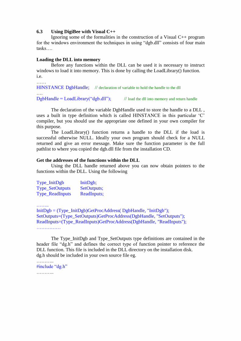
6.3 Using DigiBee with Visual C++
Ignoring some of the formalities in the construction of a Visual C++ program
for the windows environment the techniques in using “dgb.dll” consists of four main
tasks….
Loading the DLL into memory
Before any functions within the DLL can be used it is necessary to instruct
windows to load it into memory. This is done by calling the LoadLibrary() function.
i.e.
……
HINSTANCE DgbHandle; // declaration of variable to hold the handle to the dll
….
DgbHandle = LoadLibrary(“dgb.dll”); // load the dll into memory and return handle
The declaration of the variable DgbHandle used to store the handle to a DLL ,
uses a built in type definition which is called HINSTANCE in this particular ‘C’
compiler, but you should use the appropriate one defined in your own compiler for
this purpose.
The LoadLibrary() function returns a handle to the DLL if the load is
successful otherwise NULL. Ideally your own program should check for a NULL
returned and give an error message. Make sure the function parameter is the full
pathlist to where you copied the dgb.dll file from the installation CD.
Get the addresses of the functions within the DLL
Using the DLL handle returned above you can now obtain pointers to the
functions within the DLL. Using the following
Type_InitDgb InitDgb;
Type_SetOutputs SetOutputs;
Type_ReadInputs ReadInputs;
……..
InitDgb = (Type_InitDgb)GetProcAddress( DgbHandle, "InitDgb");
SetOutputs=(Type_SetOutputs)GetProcAddress(DgbHandle, "SetOutputs");
ReadInputs=(Type_ReadInputs)GetProcAddress(DgbHandle, "ReadInputs");
……………
The Type_InitDgb and Type_SetOutputs type definitions are contained in the
header file “dg.h” and defines the correct type of function pointer to reference the
DLL function. This file is included in the DLL directory on the installation disk.
dg.h should be included in your own source file eg.
………..
#include “dg.h”
………..

The call to GetProcAddress() returns a pointer to this function if found within
the DLL otherwise NULL. Once the functions pointers have been obtained in this
way the internal functions within the DLL are simply accessed like ordinary function
calls e.g.
………..
InitDgb ();
SetOutputs(0x00001234);
ReadInputs(&inputvalue)
…………
Initialising The DLL
Once the addresses of the DLL functions are obtained as above the remaining
functions required to use them are very simple. The first step is to initialise the DLL
using….
int status;
……..
status = InitDgb();
Your program should check to see if a value of ‘1’ has been returned by
InitDgb (). Any other value indicates an error. e.g. Digi-Bee not connected etc…
Using the SetOutputs() Function
This simply applies the pattern of 1’s and 0’s of the 16 bit parameter directly
to the outputs. For example: to create a pattern of alternate on and off over all outputs
use..
SetOutputs(0x5555); // hexadecimal number
Or to turn on just output 1 only, use …
SetOutputs(0x0001); // hexadecimal number
etc……….
More generally…..
integer bits;
………..
bits = 0x1234; // hexadecimal number
SetOutputs(bits);
………..
This example will turn on outputs 13, 10, 6, 5 and 3.
i.e. the least significant bit of each parameter corresponding to the lowest numbered
output .

Using the ReadInputs() Function
This will read the pattern of 1’s and 0’s currently on the Digi-Bee inputs
directly to the 16 bit parameter supplied. For example: if inputs 1, 3 and 5 are on the
following call………
ReadInputs(&inputval); // inputval previously declared as integer
Will result in the variable inputval containing the value 0x0015 (hexadecimal)
Although this only gives a glimpse of the possibilities of writing your own
programs, it should be apparent that the use of the DLL functions greatly simplifies
this process. It frees the programmer from the task of getting to know the fine details
of programming USB interface communications and lets him concentrate on the main
function of reading inputs and setting outputs.
7. Minimum PC System Requirements
Digi-Bee and Logic-Lab software do not require a high spec PC for
correct operation, but the following system is suggested as a sensible Minimum
Processor 500MHz Pentium
Memory 64MB
HDD 10MB free space required
Screen Resolution 1024x768 (256 colours)
Interface One free USB socket (1.0 or 2.0)
Operating System All Windows versions which are XP or later
WARNING: The Digi-Bee adaptor board is intended for standard 5 volt
digital signals. It should not be connected directly to mains voltages
under any circumstances.

DigiBee
Regulatory Compliance and Safety Information
Product Name: DigiBee
Part No. BRD025
IMPORTANT PLEASE RETAIN THIS INFORMATION FOR FUTURE REFERENCE
Warnings
- This product should not be connected to mains voltages under any circumstances.
- This product should be placed on a stable, flat, non-conductive surface in use and should not be
contacted by conductive items.
- The connection of non CE compliant devices may affect overall compliance or result in
damage to the unit and invalidate the warranty.
Instructions for safe use
- To avoid malfunction or damage to your board please observe the following:
- Do not expose it to water, moisture or place on a conductive surface whilst in operation.
- Do not expose it to heat from any source; the MotorBee is designed for reliable operation at
normal ambient room temperatures.
- Take care whilst handling to avoid mechanical or electrical damage to the printed circuit board
and connectors.
- Avoid handling the board while it is powered. Only handle by the edges to minimize the risk
of electrostatic discharge damage.
- All peripherals used with the board should comply with relevant standards for the country
of use and be marked accordingly to ensure that safety and performance requirements are met.
Compliance Information
- The board complies with the relevant provisions of the RoHS Directive for the European Union.
WEEE Directive Statement for the European Union
- In common with all Electronic and Electrical products the board should not be disposed of in
household waste. Alternative arrangements may apply in other jurisdictions.
EMC Compliance Statements
European Union (EU) Electromagnetic Compatibility Directive Compliance Statement
This product is in conformity with the protection requirements of EU Council Directive
2004/108/EC on the approximation of the laws of the Member States relating to electromagnetic
compatibility.
Warning: This is equivalent to an EN 55022 Class A product. In a domestic environment this product
may cause radio interference in which case the user may be required to take adequate measures.
PC Control Ltd. 18 Beech Close, Desborough, Kettering, Northants NN14 2XQ, UK
www.pc-control.co.uk

Terms of Use for all Goods Supplied
Definitions
‘Supplier’ shall mean PC Control Ltd.
‘Buyer’ shall mean the person, company or any other body that purchases or agrees to purchase Goods.
‘Goods’ shall mean all goods and services which the Buyer agrees to buy from the Supplier including
replacements for defective Goods, hardware, documentation and software products licensed for use by
the Buyer.
Use of the Goods in any way by the Buyer constitutes acceptance of these terms and conditions.
Terms and Conditions
1. The Goods are intended to be part of the buyer’s own design of apparatus and not a finished
product in their own right.
2. The Goods supplied are not to be used in any design where there is a risk, however small,
either directly or indirectly, of death or personal injury.
3. The Buyer will be responsible for ensuring the fitness for purpose of the Goods for the
Buyer’s application.
4. To the extent permitted by law, the Supplier accepts no liability whatsoever or howsoever
arising in respect of loss, damage or expense arising from errors in information or advice
provided whether or not due to the Supplier’s negligence or that of its employees, agents or
sub-contractors save for any loss or damage arising from death or personal injury.
5. To the extent permitted by law, the Supplier shall not be liable to the Buyer by reason of any
representation (unless fraudulent), or any implied warranty, condition or other term, or any
duty at common law, or under the express terms of any Contract with the Buyer, for any
indirect, special or unforeseen loss or damage (whether for loss of profit or otherwise), costs,
expenses or other claims for compensation whatsoever (whether caused by the negligence of
the Supplier, its employees or agents or otherwise) which arise out of or in connection with
the supply of the Goods or their use or resale by the Buyer.
6. The entire liability of the Supplier under or in connection with the Contract with the Buyer
shall not exceed the price of the Goods except as expressly provided in these terms and
conditions.
7. These terms are an important part of the full terms and conditions of business as published on
the website at www.pc-control.co.uk/general-terms.htm which also apply.
If you cannot agree to the terms and conditions of use of the DigiBee then you should return the
DigiBee to the supplier within 7 days of receipt to receive a refund. Your use of the board or the
associated software in any way whatsoever will be regarded as an acceptance of these terms and
conditions.
All copyright PC Control Ltd. 2009-2018