digi connect and connectport ts family user guide · pdf filerevisionhistory—90000565...
TRANSCRIPT

Digi Connect® Family andConnectPort® TS Family
User Guide

Revision history—90000565
Revision Date Description
P September2013
Applied branding changes to all text strings, screen captures, commandoptions, and command output.
P1 April 2014 Updated Digi Connect ES 4/8 and Digi Connect 4/8 with Switch paragraph.
R June 2015 Added information on ConnectPort TS 16 MEI. Resolved documentationissues.
S April 2016 Added support for Connect Port TS 8 48VDC and TS 16 48VDC. Deletedreferences to the Digi Device Setup Wizard. Removed references to ConnectTS W. Resolved documentation issues.
T February2017
Updated and rebranded the documentation with minor updates. AddedX.509 Certificate/Key Management information. Added international EMCstandards information.
Trademarks and copyrightDigi, Digi International, and the Digi logo are trademarks or registered trademarks in the UnitedStates and other countries worldwide. All other trademarks mentioned in this document are theproperty of their respective owners.© 2017 Digi International Inc. All rights reserved.
DisclaimersInformation in this document is subject to change without notice and does not represent acommitment on the part of Digi International. Digi provides this document “as is,” without warranty ofany kind, expressed or implied, including, but not limited to, the implied warranties of fitness ormerchantability for a particular purpose. Digi may make improvements and/or changes in this manualor in the product(s) and/or the program(s) described in this manual at any time.
WarrantyTo view product warranty information, go to the following website:www.digi.com/howtobuy/terms
Send commentsDocumentation feedback: To provide feedback on this document, send your comments [email protected].
Customer supportDigi Technical Support: Digi offers multiple technical support plans and service packages to help ourcustomers get the most out of their Digi product. For information on Technical Support plans andpricing, contact us at +1 952.912.3444 or visit us at www.digi.com/support.
Digi Connect Family and ConnectPort TS Family 2

Contents
About this guideImportant safety information 8Where to find information 8
Digi Connect and ConnectPort TS Family featuresUser interfaces 10Network services 10IP protocol support 11
Serial data communication over TCP and UDP 11RealPort software 13
Encrypted RealPort 14Alarms 14Modem emulation 14Security features in Digi devices 14
Secure access and authentication 14Encryption 15SNMP security 16
Configuration management 16Customization capabilities 16Network connections and data paths 17
Network services 17Network/serial clients 18
Getting started with Digi Connect and ConnectPort TS FamilyproductsAssign an IP address 21
Default IP address and DHCP settings 21Configuring IP addresses 21Test the IP address assignment 23
Sign in to the web interface 23Use a web browser to sign in to the web interface 23Use Digi Device Discovery utility to sign in to the web interface 23
HardwareRack Mounting (ConnectPort TS 16 models) 26
Safety and installation considerations 26
Digi Connect Family and ConnectPort TS Family 3
Digi Connect Family and ConnectPort TS Family 4
Configuration, monitoring, and administrationConfiguration capabilities 29Digi Device Discovery utility 29Remote Manager interface 29Web interface 30Accessing the command-line interface 30Remote Command Interface (RCI) 31SNMP 31Device administration 32
Digi Connect and ConnectPort TS Family web interfaceHome page 34
Menu 34Getting started 34System summary 34
Apply and save changes 34Cancel changes 34Online help 34Configuration through the web interface 35
Network configuration 35Serial ports configuration 53GPIO pins 68Alarms Configuration 70System Configuration 73Configuration through Digi Remote Manager 91Alternative configuration options for Digi Connect Wi-SP 93Batch configuration capabilities 95
Management 96Web interface 96Manage connections and services 96Event logging 97Manage network services 97
Administration 97File Management 98X.509 Certificate/Key Management 99Backup/Restore 104Update the firmware and boot/POST code 105Factory Default Settings 105System Information 109Activate the Find Me LED 113Reboot 113Enable/disable access to network services 113
Digi Connect and ConnectPort TS Family command-line interfaceConfiguration through the command line 115
Access the command-line interface 115Basics for using the command-line interface 115Basics for using the command-line interface 115
Management through the command line interface 116close 117connect 117

Digi Connect Family and ConnectPort TS Family 5
display 117exit and quit 118info 118newpass 119ping 119reconnect 119rlogin 119send 119sendmode 119set alarm 119set autoconnect 119set buffer and display buffers 120set forward 120set gpio 120set group 120set host 120set mgmtconnection 120set mgmtglobal 120set mgmtnetwork 120set network 120set permissions 120set pmodem 120set pppoutbound 120set ppp 121set profiles 121set realport 121set rtstoggle 121set serial 121set service 121set snmp 121set system 121set tcpserial 121set usb 121set udpserial 121set user 122set wlan 122set wlan 122status 122show 122telnet 122who and kill 122
Administration 122
Remote Manager monitoring capabilitiesRemote Manager device management 125
SNMP device monitoring capabilitiesSupported RFCs and MIBs 126SNMP configuration 127Download a Digi MIB 128Supported SNMP traps 128

Digi Connect Family and ConnectPort TS Family 6
Latency tuningAchieving deterministic IP performance 130
Best-case scenario for achieving deterministic IP networking behavior 130Step 1: Determine the characteristics of your application 130Step 2: Determine the latency budget and type of latency 130Step 3: Optimize the physical layer 130Step 4: Optimize the network and transport layers 131
Command options for optimizing network and transport layers 131Considerations for using latency-related command options 132
Step 5: Optimize the application layer 133
Specifications and certificationsHardware specifications 135
Digi Connect ES specifications 135ConnectPort TS 8 specifications 136ConnectPort TS 16 specifications 137ConnectPort TS 4x4 and ConnectPort TS 4x2 specifications 138
Wireless networking features 138Digi Connect and ConnectPort TS Family regulatory information and certifications 140
RF exposure statement 141FCC certifications and regulatory information (USA only) 141Industry Canada (IC) certifications 142International EMC (Electromagnetic Emmissions/Immunity/Safety) standards 142
TroubleshootingTroubleshooting resources 145System status LEDs 145
Digi Connect Family LEDs 145ConnectPort TS Family Products 151

About this guide
This guide describes how to install, provision, configure, monitor, and administer Digi Connect andConnectPort TS Family devices. The guide covers the following products:
n Digi Connect products:
l Digi Connect SP
l Digi Connect Wi-SP
l Digi Connect ME
l Digi Connect ME 4 MB
l Digi Connect Wi-ME
l Digi Connect EM
l Digi Connect Wi-EM
l Digi Connect ES 4/8 SB
l Digi Connect ES 4/8 SB with Switch
n Digi ConnectPort TS products:
l ConnectPort TS 8 and 16
l ConnectPort TS 8 MEI and TS 16 MEI
l ConnectPort TS 8 48VDC and TS 16 48VDC
l ConnectPort TS 4x4
Digi Connect Family and ConnectPort TS Family 7

About this guide Important safety information
Digi Connect Family and ConnectPort TS Family 8
Important safety informationTo avoid contact with electrical current:
n Never install electrical wiring during an electrical storm.
n Never install an Ethernet connection in wet locations unless that connector isspecifically designed for wet locations.
n Use caution when installing or modifying lines.
n Use a screwdriver and other tools with insulated handles.
n Wear safety glasses or goggles.
n Do not place Ethernet wiring or connections in any conduit, outlet or junction boxcontaining electrical wiring.
n Installation of inside wire may bring you close to electrical wire, conduit,terminals and other electrical facilities. Extreme caution must be used to avoidelectrical shock from such facilities. Avoid contact with all such facilities.
n Ethernet wiring must be at least 6 feet from bare power wiring or lightning rodsand associated wires, and at least 6 inches from other wire (antenna wires,doorbell wires, wires from transformers to neon signs), steam or hot water pipes,and heating ducts.
n Do not place an Ethernet connection where it would allow a person to use anEthernet device while in a bathtub, shower, swimming pool, or similar hazardouslocation.
n Protectors and grounding wire placed by the service provider must not beconnected to, removed, or modified by the customer.
n Do not touch uninsulated Ethernet wiring if lightning is likely.
n External wiring: Any external communications wiring installed needs to beconstructed to all relevant electrical codes. In the United States this is theNational Electrical Code Article 800. Contact a licensed electrician for details.
Where to find informationIn addition to this guide, you can find additional product and feature information in these documents:
n Digi Connect ES Device Server Hardware Setup Guide
n RealPort® Installation Guide
For product support resources visit the following support pages:
n Digi Connect Family and ConnectPort TS Family serial servers
For additional information, see the following resources:n Online help and tutorials in the web interface for the Digi device
n Digi Wiki for Developers

About this guide Where to find information
Digi Connect Family and ConnectPort TS Family 9
n Product information available on the Digi website, www.digi.com, and the Digi support site,including:l Support forum
l Knowledge Base
l Datasheets/product briefs
l Application/solution guides
l Carrier-specific documents

Digi Connect and ConnectPort TS Family features
This section provides an overview of Digi Connect and ConnectPort TS Family features.
User interfacesYou can use the following user interfaces to configure, monitor, and administer Digi devices:
n Digi Remote Manager
n Web-based interface
n Command-line interface available via local serial port, telnet or SSH
n Remote Command Interface (RCI) over the serial port
n Simple Network Management Protocol (SNMP)
Network servicesYou can enable or disable access to network services. This means that you can restrict a device’s useof network services to those strictly needed by the device. To improve device security, you can disablenon-secure services. You can enable or disable the following network services:
n Advanced Digi Discovery Protocol (ADDP)
n RealPort
n Encrypted RealPort
n HTTP/HTTPS
n Line Printer Daemon (LPD)
n Remote login (rlogin)
n Remote shell (rsh)
n SNMP
n Telnet
n Socket connectivity to the serial ports (for example, reverse telnet, reverse SSH, raw socket,and UDP)
You can enable or disable access to network services from the Network Services Settings page in theweb interface. For more information, see Network Services Settings.You can use the set service command to enable and disable network services from the command-lineinterface. See the Digi Connect® Family Command Reference on www.digi.com for a description of theset service command.
Digi Connect Family and ConnectPort TS Family 10

Digi Connect and ConnectPort TS Family features IP protocol support
Digi Connect Family and ConnectPort TS Family 11
IP protocol supportAll Digi Connect and ConnectPort TS Family devices include an on-board TCP/IP stack with a built-inweb server. Supported protocols vary by specific product and include, unless otherwise noted:
n Transmission Control Protocol (TCP)
n User Datagram Protocol (UDP)
n Dynamic Host Configuration Protocol (DHCP)
n Simple Network Management Protocol (SNMP)
n Secure Sockets Layer (SSL)/Transport Layer Security (TLS)
n Remote login (rlogin)
n Line Printer Daemon (LPD)
n HyperText Transfer Protocol (HTTP)/HyperText Transfer Protocol over Secure Socket Layer(HTTPS)
n Simple Mail Transfer Protocol (SMTP)
n Internet Control Message Protocol (ICMP)
n Internet Group Management Protocol (IGMP)
n Address Resolution Protocol (ARP)
n Advanced Digi Discovery Protocol (ADDP)
n Network Address Translation (NAT)/Port Forwarding (only some products have NAT)
Serial data communication over TCP and UDPDigi Connect and ConnectPort TS Family products support serial data communication over TCP andUDP. The key features include:
n Serial data communication over TCP can automatically perform the following functions:l Establish bi-directional TCP connections, known as autoconnections, between the serial
device and a server or other network device. Autoconnections are based on data and/orserial hardware signals.
l Control forwarding characteristics based on size, time, and pattern.
l Allow incoming raw, telnet, and SSL/TLS (secure-socket) connections.
l Support RFC 2217, an extension of the telnet protocol.
n Serial data communication over UDP can automatically perform the following functions:l Digi Connect products can automatically send serial data to one or more devices or
systems on the network using UDP sockets. Options for sending data include whetherspecific data is on the serial line, a specific time period has elapsed, or after the specifiednumber of bytes has been received on the serial port.
l Control forwarding characteristics based on size, time, and patterns.
l Support incoming datagrams from multiple destinations.
l Support outgoing datagrams sent to multiple destinations.
n TCP/UDP forwarding characteristics.

Digi Connect and ConnectPort TS Family features IP protocol support
Digi Connect Family and ConnectPort TS Family 12
n Extended communication control on TCP/UDP data paths.l Timeout
l Hangup
l User-configurable Socket ID string (text string identifier on autoconnect only)
Dynamic Host Configuration Protocol (DHCP)You can use Dynamic Host Configuration Protocol (DHCP) to automatically assign IP addresses, deliverIP stack configuration parameters such as the subnet mask and default router, and provide otherconfiguration information. For more details, see Assign an IP address using DHCP.
Auto IPThe Auto-IP protocol automatically assigns an IP address from a reserved pool of standard Auto-IPaddresses to the computer on which it is installed. Digi devices automatically obtain their IPaddresses from a DHCP server. If the DHCP server is unavailable or nonexistent, Auto-IP assigns thedevice an IP address. For more details, see Assign an IP address using Auto-IP.
Simple Network Management Protocol (SNMP)Simple Network Management Protocol (SNMP) manages andmonitors network Digi Connect andConnectPort TS Family devices. The SNMP architecture enables a network administrator to manage:
n Nodes—servers, workstations, routers, switches, and hubs—on an IP network.
n Network performance, such as finding and solving network problems, and planning for networkgrowth.
Digi devices support SNMP Versions 1 and 2.For a list of SNMP-related of supported Request for Comments (RFCs) and Management InformationBases (MIBs), see Supported RFCs and MIBs.
Secure Sockets Layer (SSL)/Transport Layer Security (TLS)Secure Sockets Layer (SSL)/Transport Layer Security (TLS) provides authentication and encryption forDigi Connect and ConnectPort TS Family products. For more information, see Security features in Digidevices.
TelnetDigi Connect and ConnectPort TS Family devices support the following types of telnet connections:
n Telnet client
n Telnet server
n Reverse telnet, often used for console management or device management
n Telnet autoconnect
n RFC 2217, Telnet Com Port Control Option, an extension of the telnet protocol
For more information on these connections, see Network connections and data paths. You can enableor disable access to telnet network services.
Remote login (rlogin)You can enable or disable access to rlogin service. When enabled, users can use rlogin to remotely signin to systems.

Digi Connect and ConnectPort TS Family features RealPort software
Digi Connect Family and ConnectPort TS Family 13
Line Printer Daemon (LPD)The Line Printer Daemon (LPD) allows network printing over a serial port. Each serial port has adedicated LPD server that is independently configurable. You can enable or disable access to LPDservice.
HyperText Transfer Protocol (HTTP)/HyperText Transfer Protocol over SecureSocket Layer (HTTPS)Digi provides web pages that you can use to configure the Digi Connect and ConnectPort TS Familyproduct. You can secure these web pages by requiring a user login.
Internet Control Message Protocol (ICMP)You can display ICMP statistics, including the number of:
n Messages received
n Badmessages received
n Destination unreachable messages received
Point-to-Point Protocol (PPP)The Point-to-Point Protocol (PPP) transports multi-protocol packets over point-to-point links. PPP isresponsible for:
n Encapsulating the data packet
n Allowing the server to inform the dial-up client of its IP address (or client to request the IPaddress)
n Authenticating the exchange
n Negotiating multiple protocols
n Reassembling the data packet for network communication
Advanced Digi Discovery Protocol (ADDP)The ADDP runs on any operating system capable of sending multicast IP packets on a network. ADDPallows the system to identify all ADDP-enabled Digi Connect and ConnectPort TS Family productsattached to a network by sending out a multicast packet. The Digi Connect and ConnectPort TSFamily products respond to the multicast packet and identify themselves to the client sending themulticast.ADDP communicates with the IP stack using UDP. The IP stack can receive multicast packets andtransmit datagrams on a network.You can enable or disable access to ADDP service, but you cannot change the network port number forADDP from its default.
RealPort softwareDigi’s RealPort software leverages the TCP/IP network infrastructure to provide a virtual connectionto serial devices. The software is installed directly on the server and allows applications to talk todevices via a Digi device server or terminal server over a network.RealPort software is a COM port redirector that allows multiple connections to multiple ports over asingle TCP/IP connection. This means RealPort supports the maximum number of remote devices. Thenumber is restricted only by the operating system and server processing power.
Digi Connect and ConnectPort TS Family features Alarms
Digi Connect Family and ConnectPort TS Family 14
Other unique features include full hardware and software flow control, as well as tunable latency andthroughput. With these, RealPort ensures optimum performance since data transfer is adjustedaccording to specific application requirements. It also provides connection recovery—after a networkinterruption RealPort automatically reconnects the device to the COM port without the applicationknowing there was a failure.
Encrypted RealPortDigi Connect and ConnectPort TS Family devices also support RealPort software with encryption.Encrypted RealPort offers a secure Ethernet connection between the COM or TTY port and a deviceserver or terminal server. Encryption prevents internal and external snooping of data across thenetwork by encapsulating the TCP/IP packets in an SSL connection and encrypting the data usingAdvanced Encryption Standard (AES).Digi’s RealPort with encryption driver has earned Microsoft’s Windows Hardware Quality Lab (WHQL)certification.Drivers are available for a wide range of operating systems, including Microsoft Windows and Linux x32and x64 based operating systems, as well as other versions of Unix. See the RealPort Compatibility OSList in the Digi Knowledge Base for a detailed list of supported operating systems. It is ideal forfinancial, retail/point-of-sale, government, or any application requiring enhanced security to protectsensitive information.
AlarmsYou can configure Digi Connect and ConnectPort TS Family products to issue alarms, in the form ofemail messages or SNMP traps, when certain device events occur, including:
n Changes in GPIO signals (on embedded products)
n Data patterns detected in the data stream
Configuring Digi devices to issue alarms allows you to know when events occur. For more informationon configuring alarms, see Alarms Configuration.
Modem emulationDigi Connect and ConnectPort TS Family devices include a configuration profile that allows the deviceto emulate a modem. Modem emulation sends and receives modem responses to a serial device overTCP/IP (including Ethernet) instead of Public Switched Telephone Network (PSTN). The modememulation profile allows you to maintain a current software application but using it over the lessexpensive Ethernet network. In addition, you can enable or disable telnet processing on the incomingand outgoing modem-emulation connections. For information on the modem-emulation commandsthat Digi Connect and ConnectPort TS Family products support, see the Digi Connect® FamilyCommand Reference. See Select Port Profile for more information.
Security features in Digi devicesThis section covers Digi Connect and ConnectPort TS Family security features.
Secure access and authenticationSecurity features include the following:
Digi Connect and ConnectPort TS Family features Security features in Digi devices
Digi Connect Family and ConnectPort TS Family 15
n Provide customized permissions controls to locally defined users. The local definitions applyirrespective of whether Radius is used for authentication.
n Issue passwords for device users.
n Selectively enable/disable network services such as ADDP, RealPort, Encrypted RealPort,HTTP/HTTPS, LPD, remote login, remote shell, SNMP, and telnet.
n Control access to inbound ports.
n Control access to specific devices, IP addresses, or networks through IP filtering.
n Secure sites for configuration: HTML pages for configuration have appropriate security.
n Control user and user group access permissions. These permissions control user access tovarious features and the level of control they have over them (view settings or changesettings).
n Enable secure remote login through Remote Authentication Dial-In User Service (RADIUS) andLightweight Directory Access Protocol (LDAP).
EncryptionEncrypted RealPort offers encryption for the Ethernet connection between the COM/TTY port and theDigi Connect and ConnectPort TS Family product. Encryption prevents internal and external snoopingof data across the network by encapsulating the TCP/IP packets in an SSL connection and encryptingthe data using the Advanced Encryption Standard (AES) security algorithm.Encryption methods are as follows:
n Strong TLS V1.0-based encryption:l DES (64-bit)
l 3DES (192-bit)
l AES (128/192/256-bit)

Digi Connect and ConnectPort TS Family features Configuration management
Digi Connect Family and ConnectPort TS Family 16
n Wireless Digi Connect products provide Wi-Fi Protected Access (WPA/WPA2—/802.11i) andWired Equivalent Privacy (WEP) encryption (64-/128-bit). Supported WPA/WPA2—/802.11iauthentication methods include:
Supported WPA authentication methods
EAP-TLS PEAP EAP/TTLS
LEAP(WEP only)
EAP-PEAP/MSCHAPv2 (both PEAPv0 andPEAPv1)EAP-PEAP/TLS (both PEAPv0 and PEAPv1)EAP-PEAP/GTC (both PEAPv0 and PEAPv1)EAP-PEAP/OTP (both PEAPv0 and PEAPv1)EAP-PEAP/MD5-Challenge (both PEAPv0 andPEAPv1)
EAP-TTLS/EAP-MD5-Challenge
EAP-TTLS/EAP-GTC
EAP-TTLS/EAP-OTP
EAP-TTLS/EAP-MSCHAPv2
EAP-TTLS/EAP-TLS
EAP-TTLS/MSCHAPv2
EAP-TTLS/MSCHAP
EAP-TTLS/PAP
EAP-TTLS/CHAP
SNMP securityYou can configure SNMP set commands to use SNMP read-only. Digi recommends changing the publicand private community names to prevent unauthorized access to the Digi device.
Configuration managementOnce a Digi Connect and ConnectPort TS Family device is configured and running, you may need toperiodically perform the following configuration-management tasks:
n Copy configurations to and from a remote host
n Perform the following on the Digi device:l Update the firmware
l Reset the factory settings
l Manage the device files andmemory
l Reboot the device
For more information on these configuration-management tasks, see Administration.
Customization capabilitiesYou can customize several aspects of Digi devices. For example, you can:
Digi Connect and ConnectPort TS Family features Network connections and data paths
Digi Connect Family and ConnectPort TS Family 17
n Customize the appearance of the device interface by changing the company logo or screencolors.
n Run custom Python applications.
n Define the custom factory defaults that the devices use to restore factory default settings.
Network connections and data pathsDigi Connect and ConnectPort TS Family devices allow for several kinds of connections and paths fordata flow between Digi Connect and ConnectPort TS Family devices and other entities. You can groupthese connections into two main categories:
n Network services, in which a remote entity initiates a connection to a Digi device.
n Network/serial clients, in which a Digi device initiates a network connection or opens a serialport for communication.
The following topics describe the effects of enabling features and selecting settings when configuringDigi Connect and ConnectPort TS Family devices.
Network servicesA network service connection occurs when a remote entity initiates a connection to a Digi device.There are several categories of network services:
n Network services associated with specific ports
n Network services associated with serial ports in general
n Network services associated with the command-line interface
Network services associated with specific portsThe following list details network services associated with specific ports.
n Reverse telnet: A remote entity establishes a telnet connection to a Digi serial port. Datapasses transparently between the telnet connection and a named serial port.
n Reverse raw socket: A remote entity establishes a raw TCP socket connection to a Digi serialport. Data passes transparently between the socket and a named serial port.
n Reverse TLS socket: A remote entity establishes an encrypted raw TCP socket connection to aDigi serial port. Data passes transparently to and from a named serial port.
n LPD: A remote entity establishes a TCP connection to a named serial port. The Digi deviceinterprets the LPD protocol and sends a print job out of the serial port.
n Modem emulation, also known as pseudo-modem (pmodem): A remote entity establishes aTCP connection to a named serial port. This connection is “interpreted” as an incoming call tothe pseudo-modem.
Network services associated with serial ports in generalThe following list details network services associated with serial ports in general.

Digi Connect and ConnectPort TS Family features Network connections and data paths
Digi Connect Family and ConnectPort TS Family 18
n RealPort: A single TCP connection manages (potentially) multiple serial ports.
n Modem emulation, also known as pseudo-modem (pool): A TCP connection to the “pool” portis interpreted as an incoming call to an available pseudo-modem in the “pool” of available portnumbers.
n rsh: Digi Connect and ConnectPort TS Family products support a limited implementation of theremote shell (rsh) protocol, in that a single service listens to connections and allows acommand to be executed. Only one class of commands is allowed: a single integer thatspecifies which serial port to connect to. Otherwise, the resulting connection is somewhatsimilar to a reverse telnet or reverse socket connection.
n DialServ: Connecting a DialServ device to the serial port. DialServ simulates a public switchedtelephone network (PSTN) to a modem and forwards the data to the serial port. The Digidevice sends and receives the data over an IP network.
n Reverse SSH: An encrypted TCP socket is available for each port that provides a directconnection to the designated serial port.
n Reverse telnet: A telnet unencrypted socket is available for each serial port that provides atelnet style connection directly to the serial port.
n Raw TCP: A raw TCP unencrypted socket is available for each serial port that provides an 8-bitclean connection to the serial port
n TLS/SSL: An TLS/SSL encrypted raw TCP socket is available for each serial port that providesan 8-bit clean connection to the serial port.
Network services associated with the command-line interfaceThe following list details network services associated with the command line interface (CLI).
n Telnet: Use telnet to directly access a Digi Connect and ConnectPort TS Family command-lineinterface.
n Rlogin: Perform a remote login (rlogin) to a Digi Connect and ConnectPort TS Familycommand-line interface.
Network/serial clientsA network/serial client connection occurs when a Digi Connect and ConnectPort TS Family productinitiates a network connection or opens a serial port for communication. There are several categoriesof network/serial client connections:
n Autoconnect behavior client connections
n Command-line interface (CLI)-based client connections
n Modem emulation (pseudo-modem) client connections
Autoconnect behavior client connectionsIn client connections that involve autoconnect behaviors, a Digi Connect and ConnectPort TS Familyproduct initiates a network connection based on timing, serial activity, or serial modem signals.Autoconnect-related client connections include:

Digi Connect and ConnectPort TS Family features Network connections and data paths
Digi Connect Family and ConnectPort TS Family 19
n Raw TCP connection: The Digi Connect and ConnectPort TS Family initiates a raw TCP socketconnection to a remote entity.
n Telnet connection: The Digi Connect and ConnectPort TS Family initiates a TCP connectionusing the telnet protocol to a remote entity.
n Raw TLS encrypted connection: The Digi Connect and ConnectPort TS Family initiates anencrypted raw TCP socket connection to a remote entity.
n Rlogin connection: The Digi Connect and ConnectPort TS Family initiates a TCP connectionusing the rlogin protocol to a remote entity.
Command-line interface (CLI)-based client connectionsCLI-based client connections are available for use when you establish a session with the Digi Connectand ConnectPort TS Family product’s CLI. CLI-based client connections include:
n ssh: Allows you to connect to a remote entity using the ssh protocol.
n telnet: Allows you to connect to a remote entity using the telnet protocol.
n rlogin: Allows you to connect to remote entity using the rlogin protocol (bash only).
n scp: Allows you to transfer files (bash only).
n connect: Begin communicating with a local serial port.
Note Additional communication methods include using a bash shell such as scp, tftp, nc, or usingPython.
Modem emulation (pseudo-modem) client connectionsWhen a port is in the modem-emulation or pseudo-modemmode, it can initiate network connectionsbased on AT command strings received on the serial port. See the Digi Connect® Family CommandReference on www.digi.com for modem emulation AT commands.

Getting started with Digi Connect and ConnectPortTS Family products
This section walks you through configuring an IP address and signing in to your Digi Connect andConnectPort TS Family device.
Assign an IP address 21Sign in to the web interface 23
Digi Connect Family and ConnectPort TS Family 20

Getting started with Digi Connect and ConnectPort TS Family products Assign an IP address
Digi Connect Family and ConnectPort TS Family 21
Assign an IP addressThis section describes how to assign an IP address to Digi Connect and ConnectPort TS Familyproducts andmanage that IP address.
Default IP address and DHCP settingsAll products that have a cellular (WAN) interface ship with a static IP address for the Ethernet port of192.168.1.1 and DHCP server enabled by default. Configure the Ethernet port on the laptop toautomatically receive an IP address and DNS server address.All products that only have an Ethernet or Wi-Fi (LAN) interface ship with DHCP client enabled bydefault. Accessing the web interface on these products is most easily done by connecting it to a LANthat has a DHCP server.To discover the IP address assigned to the device, use the Device Discovery Utility for Windows. SeeUse Digi Device Discovery utility to sign in to the web interface for more information.
Configuring IP addressesThere are several alternate methods to assign an IP address to a Digi device:
n Use Dynamic Host Configuration Protocol (DHCP) from the web interface.
n Use the command-line interface.
n Use Automatic Private IP Addressing (APIPA), also known as Auto-IP.
Note For the Digi Connect ES 4/8 SB with an Ethernet switch device, special considerations applywhen assigning IP addresses. See IP Settings (for Connect ES 4/8 SB with Ethernet switch only) formore information.
Assign an IP address using Auto-IPThe standard Automatic Private IP Addressing (APIPA or Auto-IP) protocol automatically assigns theIP address from a group of reserved IP addresses to the device on which Auto-IP is installed. Use DigiDevice Discovery or ADDP to find the Digi device and assign it a new IP address that is compatible withyour network. When you plug in the device, Auto-IP automatically assigns the IP address. Auto-IPaddresses are typically in the 169.254.x.x address range. See Use Digi Device Discovery utility to sign into the web interface for instructions on using Digi Device Discovery.
Assign an IP address from the command-line interfaceUse the set network command to configure an IP address from the command line. The set networkcommand includes the following parameters:
n ip=device ip: The IP address for the device.
n gateway=gateway: The network gateway IP address.
n garp=seconds: The frequency of Gratuitous ARP (GARP) announcements, in seconds, which area broadcast announcement to the network of a device’s MAC address and the IP address.
n submask=device submask: The device subnet mask for the IPaddress.
n dhcp=off: Turns off use of the Dynamic Host Configuration Protocol (DHCP), so that the IPaddress assigned is permanent.

Getting started with Digi Connect and ConnectPort TS Family products Assign an IP address
Digi Connect Family and ConnectPort TS Family 22
n static=on: Specifies that the IP address is static, and will remain as the specified IP address,gateway, and submask.
For example:
set network ip=10.0.0.100 gateway=10.0.0.1 submask=255.255.255.0 dhcp=offstatic=on
To configure the Digi Connect SP through the command line, you must change the DIP switches. SeeSet DIP switches on Digi Connect Wi-SP (or SP) for an illustration of the DIP switch settings.
Assign an IP address from the web interfaceNormally, you assign IP addresses to Digi Connect and ConnectPort TS Family devices through DHCP.This procedure assumes that the Digi Connect and ConnectPort TS Family device already has an IPaddress and you simply want to change it.To change the IP address from the web interface:
1. Open a web browser and type the current IP address of the Digi Connect and ConnectPort TSFamily device in the address bar.
2. Type the user name and password for the device. The default user name is root and the defaultpassword is dbps. If these defaults do not work, contact the system administrator who set upthe device.
3. Click Network to access the Network Configuration page.
4. On the IP Settings page, select Use the following IP address.
5. Type the IP address, subnet mask, and gateway settings.
6. Click Apply to save the configuration.
IP addresses and Remote ManagerFrom the Remote Manager interface, you can only change the Ethernet/LAN address for a Digi device;you cannot assign an address. The mobile/cellular device is typically provided by the mobile serviceprovider; check with your mobile service provider on how they handle addresses. To change the IPaddress, open the web interface for based on the IP address the device has and goConfiguration > Network > IP Settings. On the IP Settings page, type the new IP address, subnetmask, and gateway.
Assign an IP address using DHCPYou can assign an IP address using Dynamic Host Configuration Protocol (DHCP). DHCP is an Internetprotocol for automating the configuration of computers that use IP. You can use DHCP toautomatically assign IP addresses and deliver IP stack configuration parameters.All products that have a cellular (WAN) interface ship with static IP address for the Ethernet port of192.168.1.1 and DHCP server enabled by default. All products that only have an Ethernet or Wi-Fi (LAN)interface ship with DHCP client enabled by default.The following procedure assumes that you configured the Digi device as a DHCP client. The Digidevices discussed in this document are configured as a DHCP client by default.To configure an IP address using DHCP:
Getting started with Digi Connect and ConnectPort TS Family products Sign in to the web interface
Digi Connect Family and ConnectPort TS Family 23
1. Verify the Digi device is not powered on.
2. If desired, set up a permanent entry for the Digi device on a DHCP server. While this is notnecessary to obtain an IP address via DHCP, setting up a permanent entry saves the IPaddress after the device is rebooted.
3. Connect the Digi device to the network and power it on. DHCP assigns the IP addressconfigured in step 2 automatically.
Test the IP address assignmentTo verify the IP address works as configured:
1. Access the command line of a computer or other networked device.
2. Issue the following command:
ping ip-address
where ip-address is the IP address assigned to the Digi device. For example:
ping 192.168.2.2
Sign in to the web interfaceAfter you successfully assign an IP address to your device, you can sign in to the device's web interfaceusing either of the following:
n Web browser
n Digi Device Discovery utility
Use a web browser to sign in to the web interfaceTo access the web interface for a Digi device using a browser:
1. In the web browser address bar, type the IP address of the device.
2. If you are prompted for login credentials, type the user name and password for the Digi device.The default user name is root and the default password is dbps. If the default user name andpassword do not work, contact the system administrator who set up the Digi device.
The Home page appears. See Home page for an overview of the Home page and other linkedpages.
Note If password authentication is enabled, the idle timeout automatically logs users out ofthe web interface after 5 minutes of inactivity.
Use Digi Device Discovery utility to sign in to the web interfaceTo discover the Digi device and open the web interface:

Getting started with Digi Connect and ConnectPort TS Family products Sign in to the web interface
Digi Connect Family and ConnectPort TS Family 24
1. Go to your product's support page:
n DigiConnectPort X2
n DigiConnectPort X4
2. Under Product Support, click the Utilities tab.
3. Under Operating System Specific Utilities, choose an operating system.
4. Under Utilities or Operating System Specific Diagnostics, Utilities and MIBs, select eitherDevice Discovery Utility for Windows - Standalone version or Device Discovery Utility forWindows - Installable version.
The standalone version runs the utility immediately after the download is complete. Theinstallable version installs the utility on your computer and adds it to a program group in theStartmenu named Digi > Digi Device Discovery.
5. Click Run on the two dialogs. The standalone version of the utility starts immediately.
For the installable version, an installation wizard appears. Follow the prompts to complete theinstallation. To start the utility, select Start > All Programs > Digi > Digi Device Discovery >Digi Device Discovery.
6. From the Digi Device Discovery utility, locate the Digi device in the list of devices, and chooseone of the following options:
n Double-click the Digi device to open the web interface.
n Select the Digi device from the list and select Open web interface in the Device Taskslist.
If you are prompted for login credentials, type the user name and password for the Digi device.The default user name is root and the default password is dbps. If the default user name andpassword do not work, contact the system administrator who set up the Digi device.

Hardware
This section details requirements and recommendations for Digi Connect and ConnectPort TS Familyproducts. See also Specifications and certifications and System status LEDs.For the Digi Connect ES, see the Digi Connect ES Hardware Setup Guide. For all other Digi Connect andConnectPort TS Family products, see their Hardware Reference Manuals for hardware-installationdetails.
Rack Mounting (ConnectPort TS 16 models) 26
Digi Connect Family and ConnectPort TS Family 25
Hardware Rack Mounting (ConnectPort TS 16 models)
Digi Connect Family and ConnectPort TS Family 26
Rack Mounting (ConnectPort TS 16 models)You can optionally mount ConnectPort TS 16 models to an industry standard 48.260 cm (19 in)equipment rack using the mounting bracket ears provided with the product.
Safety and installation considerations
Physical location and spacingn Install equipment in Restricted Access Areas only (dedicated equipment rooms/closets) in
accordance with Articles 110-16, 110-17, and 110-18 of the National Electrical Code,ANSI/NFPA 70.
n To ensure proper ventilation and air flow for units, provide at least 12 inches (30 centimeters)of clearance on all sides for each unit.
n Distribute weight evenly in the rack to avoid overloading.
Temperaturen Elevated operating ambient temperature: If installed in a closed or multi-unit rack assembly,
the operating ambient temperature of the rack environment may be greater than roomambient temperature. Install rack-mounted equipment in an environment compatible with themanufacturer’s maximum rated ambient temperature (Tmra).
n For a rack setup with forced air, the device can run 0-55° C with no extra space above or belowthe device (default design of the ConnectPort TS 8 16 Rack provides 1/16” = 2mm betweendevices).
n For a rack setup with no forced air, sure the air in-between devices does not get warmer than55°C by providing space between the devices, controlling the ambient temperature on therack, distributing weight evenly in the rack to avoid overloading, checking equipmentnameplate ratings before connecting to the supply circuit, andmaintaining reliable earthing ofthe rack-mounted equipment.
Power and wiringn For all systems:
l This equipment is for indoor use and all the communication wirings are limited to inside ofthe building.
l Check equipment nameplate ratings before connecting to the supply circuit to avoidoverloads that may damage over-current protection devices and supply wiring.
l As neededmaintain reliable earthing of rack-mounted equipment.

Hardware Rack Mounting (ConnectPort TS 16 models)
Digi Connect Family and ConnectPort TS Family 27
n For AC Supply Systems:l Locate the AC supply source within the same premises as the equipment you are using.
The following image shows a ConnectPort TS 16 VAC with an AC plug.
The following image shows a ConnectPort TS 8 VAC with a barrel jack.
n For DC Supply Systems:l Connect equipment to a DC supply source (reliably earthed) that is electrically isolated
from the AC source.
l Provide a readily accessible disconnect device and protective device a fixed wiring for a DCpower supply suitable for the specified rated voltage and current. Disconnect andprotective devices to be rated 2A Amps maximum.
l Directly connect the equipment chassis to the DC supply system grounding electrodeconductor or a bonding jumper from a grounding terminal bar (or bus) that is connected tothe DC supply system grounding electrode conductor. In DC supply systems, the protectivegrounding wire must be a minimum 18AWG.
The following image shows the ConnectPort TS 16 48VDC with a terminal block.

Configuration, monitoring, and administration
Digi Connect Family and ConnectPort TS Family 28
Configuration, monitoring, and administration
This section provides an overview for configuring, monitoring, and administering Digi devices.
Configuration capabilities 29Digi Device Discovery utility 29Remote Manager interface 29Web interface 30Accessing the command-line interface 30Remote Command Interface (RCI) 31SNMP 31Device administration 32

Configuration, monitoring, and administration Configuration capabilities
Digi Connect Family and ConnectPort TS Family 29
Configuration capabilitiesConfiguration options provide settings for the following features:
n Network Configuration: Specifies IP address settings, network service settings, and advancednetwork settings.
n Serial Ports Configuration: Specifies serial port characteristics for the device.
n GPIO Pin Configuration (for Connect ME and Connect EM devices): Specifies how to useGPIO pins for the device.
n Alarms: Defines conditions that trigger alarms and notifications for alarms.
n System Configuration: Provides system-identifying information, such as a device description,device location, and contact information.
n Security/Users: Configures security features, such as enabling password authentication fordevice users.
Digi Device Discovery utilityThe Digi Device Discovery utility:
n Locates Digi devices on a network
n Allows you to open the web interface for discovered devices
n Allows you to configure network settings and reboot the device
Download the Digi Device Discovery utility from www.digi.com/support/productdetail?pid=5574.In addition to quickly locating devices, the utility also lists device information, such as the deviceaddress, firmware version, and whether it has been configured. It runs on any operating system thatcan sendmulticast IP packets to a network. It sends out a User Datagram Protocol (UDP) multicastpacket to all Digi devices on the network. Digi devices that support ADDP reply to the UDP multicastwith their configuration information. Even Digi devices that do not yet have an assigned IP address orare misconfigured for the subnet can reply to the UDP multicast packet and appear in the devicediscovery results.
Note Personal firewalls, Virtual Private Network (VPN) software, and certain network equipment canblock device discovery. Firewalls block UDP ports 2362 and 2363 that ADDP uses to discover devices.You can enable or disable access to the ADDP service, but you cannot change the network portnumber for ADDP.
See Use Digi Device Discovery utility to sign in to the web interface for instructions on using the utilityto sign in to the Digi Connect and ConnectPort TS Family web interface.
Remote Manager interfaceDigi Remote Manager is a software-as-a-service platform that empower IT, network operations andcustomer support organizations to manage the vast array of equipment in their device networks. As anetwork grows, the complexity of effectively managing the network assets grows exponentially.Remote Manager provides functionality that helps to manage the universal problems of a dynamicdevice network:
n Centralized control over large numbers of devices
n Reducing service complexity

Configuration, monitoring, and administration Web interface
Digi Connect Family and ConnectPort TS Family 30
n Maintaining high levels of security
n Provisioning and decommissioning of equipment
n Adding functionality to device networks
Additionally, you can group devices together, schedule various operations, and set alarm notifications.For example, you can set an alarm to send a notification if a device disconnects or remains connectedlonger than a specified period.Some things to note about using Remote Manager:
n Devices must be registered in a Remote Manager account before you can access them.
n To minimize network traffic, Remote Manager uses caching. As a result, device settings can beout-of-sync between the device and the settings viewed on the console.
n Device information refreshes on demand when the device is connected, and refreshesautomatically when a device connects.
For more information on Remote Manager as a remote device network management solution, seethese resources:
n Remote Manager User Guide
n Remote Manager Programming Guide
n Remote Manager tutorials and other documents available on Digi’s Knowledge Base
Web interfaceDigi Connect and ConnectPort TS Family devices provide a web interface for configuring andmonitoring devices. See Digi Connect and ConnectPort TS Family web interface.
Note Not all configuration options provided by the command-line interface (CLI) appears in the webinterface. If you need to configure more advanced options, see the Accessing the command-lineinterface for instructions on accessing the CLI.
Accessing the command-line interfaceYou can configure Digi devices by issuing commands from the command line. The command-lineinterface allows direct communication with a Digi device.To access the command line from the Digi Device Discovery utility, click Telnet to command line.For example, you can issue the following command from the command line to set general serialconfiguration options:
#> set serial baudrate=9600 flowcontrol=hardware
The command-line interface provides flexibility for making precise changes to device configurationsettings and operation. It requires you to have experience issuing commands and access to commanddocumentation.You can access the command line through telnet or SSH TCP/IP connections or through a serial portusing terminal emulation software such as Hyperterminal. Access to the command line from serialports depends on the port profile in use by the port. By default, serial port command-line access isallowed.See Digi Connect and ConnectPort TS Family command-line interface for more information on thisinterface. See the Digi Connect® Family Command Reference on www.digi.com for command

Configuration, monitoring, and administration Remote Command Interface (RCI)
Digi Connect Family and ConnectPort TS Family 31
descriptions and examples of entering configuration commands from the command-line interface. Inaddition, you can access online help for the commands by issuing the help and ? commands.
Remote Command Interface (RCI)The Remote Command Interface (RCI) is a programmatic interface for configuring and controlling Digidevices. RCI is an XML-based request/response protocol that allows a caller to query andmodifydevice configurations, access statistics, reboot the device, and reset the device to factory defaults.Unlike other configuration interfaces that are designed for a user, such as the command-line or webinterfaces, a program can use RCI. RCI access consists of program calls. For example, a customapplication running on a computer that monitors and controls an installation of many Digi devices.You can use RCI to create a custom configuration user interface, or utilities that configure or initializedevices through external programs or scripts.RCI uses HTTP as the underlying transport protocol. Depending on the network configuration, use ofHTTP as a transport protocol could be blocked by some firewalls.RCI is quite complex to use, requiring users to phrase configuration requests in Extensible MarkupLanguage (XML) format. It is a “power-user” option, intended for users who develop their own userinterfaces, or implement embedded control (and thus potentially using RCI over serial) than for end-users with limited knowledge of device programming.Not all actions in the web interface have direct equivalents in RCI.For more details on RCI, see the Digi Connect Integration Kit and the Remote Command Interface (RCI)Specification.
SNMPUse SNMP to manage andmonitor network devices. SNMP architecture allows you to:
n Manage nodes on an IP network, including servers, workstations, routers, switches and hubs
n Manage network performance, find and solve network problems, and plan for network growth
SNMP is easy to implement in extensive networks. You can program new variables and drop in newdevices in a network. SNMP is widely used. It is a standard interface that integrates well with networkmanagement stations in an enterprise environment.However, because device communication is UDP-based, the communication is not secure. If yourequire more secure communications with a device, use an alternate device interface. SNMP does notallow you to perform certain tasks from the web interface, such as file management, uploadingfirmware, or backing up and restoring configurations. Compared to the web or command-lineinterfaces, SNMP is limited in its ability to set specific parameters, such as set port profile, is notpossible.Accessing the SNMP interface requires a tool, such as a network management station. Themanagement station relies on an agent at a device to retrieve or update the information at thedevice, including device configuration, status, and statistical information. This information is viewed asa logical database, called a Management Information Base (MIB). MIB modules describe MIB variablesfor a variety of device types and computer hardware and software components.A variety of resources about SNMP are available, including reference books, overviews, and other fileson the Internet. For an overview of the SNMP interface and the components of MIB-II, go tohttp://www.rfc-editor.org/search/rfc_search.php, and search for MIB-II. From the results, locate thetext file describing the SNMP interface, titled Management Information Base for NetworkManagement of TCP/IP-based Internets: MIB-II. You can also display the text of the Digi enterpriseMIBs. The product page for each product on the Digi website provides a link to the Digi-provided MIBsfor that product. See Simple Network Management Protocol (SNMP) for a list of supported MIBs.
Configuration, monitoring, and administration Device administration
Digi Connect Family and ConnectPort TS Family 32
For more information about using SNMP as a device monitoring interface, see SNMP devicemonitoring capabilities.
Device administrationPeriodically, you need to perform administrative tasks on a Digi Connect and ConnectPort TS Familydevice, such as:
n Uploading andmanaging files
n Changing the password for logging onto the device
n Backing up and restoring the configuration
n Updating firmware
n Restoring the configuration to factory defaults
n Rebooting the module
As with configuration andmonitoring, you can perform administration from a number of interfaces,including the web interface, command line, and Remote Manager. See Administration for moreinformation and procedures.
Digi Connect and ConnectPort TS Family webinterface
This section describes how to configure andmanage a Digi Connect and ConnectPort TS Family deviceusing the web interface.
Home page 34Apply and save changes 34Cancel changes 34Online help 34Configuration through the web interface 35Management 96Administration 97
Digi Connect Family and ConnectPort TS Family 33

Digi Connect and ConnectPort TS Family web interface Home page
Digi Connect Family and ConnectPort TS Family 34
Home pageWhen you access the web interface, the Home page appears. The Home page provides a tutorial and asystem summary.
MenuThe left side of the web interface displays a menu. Use the menu to:
n Configure the Digi device, peripheral devices, and applications
n Manage serial ports and connections
n Administer the Digi device
Getting startedThe Getting Started section displays a link to a tutorial on configuring andmanaging Digi devices.
System summaryThe System Summary page displays the details for this Digi Connect and ConnectPort TS Family.
n Model: The model type for this Digi Connect and ConnectPort TS Family product.
n IPv6 Address (Link): The IPv6 address (link) associated with this Digi device.
n IPv6 Address (Global): The IPv6 address (global) associated with this Digi device.
n IPv4 Address: The IPv4 address associated with this Digi device.
n MAC Address: The MAC address associated with this Digi device.
n Description: A description of this Digi device.
n Contact: Contact information for the Digi device.
n Location: The location of this Digi device.
n Device ID: The serial number associated with this Digi device. The serial number appears on alabel on the Digi device.
Apply and save changesThe web interface runs locally on the Digi device, which means that the interface always maintainsand displays the current settings in the Digi device. When you change the configuration settings, clickApply to save your changes to the Digi device.
Cancel changesTo cancel changes to configuration settings, click the Refresh or Reload button on the web browser.The browser reloads the page. Any changes made since the last time you clicked Apply are reset totheir original values.
Online helpThe web interface provides online help for all pages. The Home page provides a tutorial.
Digi Connect and ConnectPort TS Family web interface Configuration through the web interface
Digi Connect Family and ConnectPort TS Family 35
Configuration through the web interfaceUse the options under Configuration to configure settings for various features, such as networksettings and serial port settings.
Network configurationThe Network Configuration page includes:
n IP settings: For viewing IP address settings and changing as needed.
n WiFI IP settings: Configure the IP address used for wireless LAN communication. See Wi-Fi IPsettings for more information.
n WiFI LAN settings: Configure basic settings for wireless LAN devices such as network nameand network connection options. See Wi-Fi LAN settings for more information.
n WiFi Security settings: Configure authentication and encryption settings for wireless LANdevices. See Wi-Fi security settings for more information.
n WiFi 802.1x Authentication settings: Configure IEEE 802.1x authentication settings forwireless LAN devices. See Wi-Fi 802.1x authentication settings for more information.
n Network Services settings: Configure access to various network services, such as ADDP,RealPort and Encrypted RealPort, telnet,HTTP/HTTPS, and other services. See NetworkServices Settings for more information.
n IP Filtering settings: Configure the IP settings for a Digi Connect and ConnectPort TS Familydevice to only accept connections from specific and known IP addresses or networks. See IPfiltering settings for more information.
n IP Forwarding settings:l Configure the IP forwarding settings for a Digi Connect and ConnectPort TS Family device
to forward certain connections to other devices. This is also known as Network AddressTranslation (NAT) or Port Forwarding.
l Configure the built-in firewall functionality to limit IP traffic to and from certain networks,TCP or UDP ports, and interfaces. This feature is based on Linux tool iptables. See IPfiltering settings for more information.
n Advanced Network Settings: Configure the Ethernet Interface speed andmode, IP settings,TCP keepalive settings, and DHCP settings. See Advanced Network Settings for moreinformation.
IP SettingsEthernet Uplink IP Settings (for Connect ES 4/8 SB with Switch)The IP Settings page allows you to configure how to obtain the IP address of the Digi Connect andConnectPort TS Family device. You can use one of the following methods to obtain the IP address:
n DHCP
n Static IP address
n Subnet mask
n Default gateway
Digi Connect and ConnectPort TS Family web interface Configuration through the web interface
Digi Connect Family and ConnectPort TS Family 36
For more information on how to assign and use these settings in your organization, contact yournetwork administrator.
IP settingsThe IP settings for all Digi devices but Digi Connect ES 4/8 SB with Switch are as follows.
n Obtain an IP address automatically using DHCP: When the Digi device is rebooted, it willobtain new network settings.
n Use the following IP Address: Choose this option to supply static settings. An IP address andSubnet mask must be entered. Other items are not mandatory, but may be needed for somefunctions (such as talking to other networks).
n IP Address: An IP address is like a telephone number for a computer. Other network devicestalk to this Digi device using this ID.
The IP address is a 4-part ID assigned to network devices. IP addresses are in the form of192.168.2.2, where each number is between 0 and 255.
n Subnet Mask: The Subnet Mask is combined with the IP address to determine which networkthis Digi device is part of. A common subnet mask is 255.255.255.0.
n Default Gateway: IP address of the computer that enables this Digi device to access othernetworks, such as the Internet.
n Enable AutoIP address assignment: With AutoIP enabled, the Digi device will automaticallyself-configure an IP address when an address is not available from other methods, for example,when the Digi device is configured for DHCP and a DHCP server is not currently available.
IP Settings (for Connect ES 4/8 SB with Ethernet switch only)This section describes configuring and deploying Digi Connect ES4/8 SB with Switch devices in anetwork.The Digi Connect ES4/8 SB with Switch has two Ethernet interfaces:
n Ethernet Uplink: An uplink interface that connects to the central data management systemnetwork.
The uplink interface provides a single Internet Protocol (IP) address for all communication toand from the devices at a single location. Network Address Translation (NAT) and portforwarding provide seamless network access through the Digi Connect ES SB SW for allEthernet and serial devices at that location. DHCP or static addresses are used for IP addressassignment of the uplink interface.

Digi Connect and ConnectPort TS Family web interface Configuration through the web interface
Digi Connect Family and ConnectPort TS Family 37
n Ethernet Switch: A four-port switch that creates a Local Area Network (LAN).
The LAN switch provides network connectivity for up to four network devices, in addition to theDigi Connect ES SB SWwhich provides four or eight isolated RS-232 serial ports. The default IPaddress for the LAN interface of the Digi Connect ES 4/8 SB with Switch is 192.168.1.1. Theother network devices connected to the Digi Connect ES 4/8 SB with Switch share this sameClass C network address scheme (192.168.1.x). A Dynamic Host Configuration Protocol (DHCP)server is provided on this interface to allow dynamic assignment of devices as well.
The following figure shows the location of the Ethernet Uplink and Switch ports on the product:
Because the LANs attached to each Digi Connect ES 4/8 SB with Switch are typically not connected toeach other, equipment can have static network addresses and be moved from one location to anotherwithout needing to be reconfigured. The central data management system can easily communicatewith the equipment by addressing the appropriate Digi Connect ES 4/8 SB with Switch device. TheDigi Connect ES 4/8 SB with Switch uses NAT and port forwarding to make the connection.See Configure the Ethernet interface for Connect ES 4/8 SB with Switch for instructions on configuringthe network topology just described.
Configure the Ethernet interface for Connect ES 4/8 SB with SwitchThese steps apply to a single Digi Connect ES 4/8 SB with Switch and its connected Ethernet and serialdevices andmust be performed for each Digi Connect ES 4/8 SB with Switch deployed.To configure the Ethernet interface for each Connect ES 4/8 SB with Switch:
1. Connect a laptop to one of the Ethernet Switch ports on theDigi Connect ES 4/8 SB with Switch and open the web interface.
The recommended IP address settings for the laptop are as follows:n IP Address: 192.168.1.99
n Subnet: 255.255.255.0
n Default Gateway: 192.168.1.1

Digi Connect and ConnectPort TS Family web interface Configuration through the web interface
Digi Connect Family and ConnectPort TS Family 38
2. From the web interface, select Configuration > Network > Ethernet Switch IP Settings, Thispage assigns IP address numbers to devices connected to the Ethernet Switch. Digirecommends that you leave the settings here as-is. The IP address for the Ethernet Switch onthe unit is set to 192.168.1.1. You can set fixed IP addresses starting at 192.168.1.2,192.168.1.3, and so on. The DHCP server assigns 192.168.1.101 and higher for devices thathave their IP addresses dynamically assigned.
3. Choose an IP address assignment mechanism and strategy for the uplink interface. Use one orthe other of these assignment mechanisms:
n Assign an IP address in the DHCP configuration file in the network DHCP server. In thiscase, no configuration change on the Digi device is necessary. The device will request aDHCP address from any visible DHCP server at startup.
Or, in the command line interface, type the following command:set network if=eth1 dhcp=on static=off autoip=off
Where eth1 is the network interface of the uplink. The autoip=off option avoidsunintentional network address problems through automatic IP address assignment ifDHCP servers are temporarily unavailable.
n Assign a static IP address. From the web interface, selectConfiguration > Network > Ethernet Uplink IP settings and type the static IPaddress.
Or, in the command line interface, type the following command:set network if=eth1 ip=<static ip address> sub=<subnet mask>
gate=<gateway> static=on
Where eth1 is the network interface of the uplink. You may also need to configure DNSserver addresses and other attributes on statically assigned interfaces.
4. Enable NAT and port forwarding for any protocols that must be forwarded to the LAN. See IPforwarding settings. You can also configure NAT and port forwarding from the command line;see the set nat and set forwarding commands in the Digi Connect and ConnectPort TS Family
Command Reference.
Network configuration is complete.
Deploy the Connect ES 4/8/SB with SwitchTo deploy the Digi Connect ES 4/8 SB with Switch after network configuration:
1. Install the Digi Connect ES 4/8 SB with Switch in the desired location.
2. Connect the Digi Connect ES 4/8 SB with Switch to the main/business Ethernet networkthrough the Ethernet Uplink connection using a straight-through Ethernet cable.
3. Connect the network devices to the Ethernet Switch ports using straight-through Ethernetcables.

Digi Connect and ConnectPort TS Family web interface Configuration through the web interface
Digi Connect Family and ConnectPort TS Family 39
4. Connect the serial devices to the serial ports.
5. Power on the Digi Connect ES 4/8 SB with Switch and all connected devices.
Wi-Fi IP settingsUse the Wi-Fi IP Settings page to configure how to obtain the IP address of a Wi-Fi-enabled Digi device.It has the same settings as the IP Settings page.
Wi-Fi LAN settingsDigi devices with Wi-Fi (wireless LAN) capability contain a wireless network interface that you may finduseful to communicate to wireless networks using 802.11b technology. Contact your administrator orconsult wireless access point documentation for the settings required to setup the wireless LANconfiguration. Different devices and firmware settings may not support all of the settings and optionslisted below. Settings include:
n Network name: The name of the wireless network to which the wireless device shouldconnect. In situations with multiple wireless networks, this setting allows the device toconnect to and associate with a specific network. The network name is the SSID (service setidentifier). If the network name remains blank, the device will search for wireless networksand connect to the first available network. This is useful when you do not need use a specificnetwork name as the device will select the first available network.
n Connection method: The type of connection method this device uses to communicate onwireless networks. Choose from:l Connect to any available wireless network: Use this setting to allow the device to
access any network. The device can either access point networks or peer-to-peer wirelessnetworks.
l Connect to access point (infrastructure) networks only: Use this setting if the wirelessnetwork that this device needs to connect to is composed of wireless access points. This istypically the most popular method for connecting to wireless networks.
l Connect to peer-to-peer (ad-hoc) networks only: Use this setting if all devices on thewireless network connect to and communicate with each other. This is known as peer-to-peer in that there is no central server or access point. Each system communicates directlywith each other system.
n Country: The country where this wireless device resides. The channel settings are restrictedto the legal set for the selected country.
n Channel: The frequency channel that the wireless radio will use. Select Auto-Scan to have thedevice scan all frequencies until it finds one with an available access point or wireless networkit can join.
n Transmit Power: The transmit power level in dBm.
n Enable Short Preamble: Enables transmission of wireless frames using short preambles. IfShort Preamble is supported in the wireless network, enabling it can boost overall throughput.

Digi Connect and ConnectPort TS Family web interface Configuration through the web interface
Digi Connect Family and ConnectPort TS Family 40
Wi-Fi security settingsUse the Wi-Fi Security Settings page to specify the wireless security settings that the wirelessnetwork uses. Multiple security and authentication modes may be chosen depending on theconfiguration of the access point or wireless network. The wireless device will automatically selectand determine the authentication and encryption methods to use while associating to the wirelessnetwork. If the wireless network does not use security and uses an Open Network architecture, thesesettings do not need to be modified.Note that WPA settings require that the device communicate to Access Points and is not valid whenthe Connection Method is set to Connect to wireless systems using peer-to-peer (ad-hoc). Also,WPA pre-shared key (WPA-PSK) security is only valid when you use a specific Network Name or SSID.
n Network Authentication: The authentication method or methods used for wirelesscommunications.l Use any available authentication method: Enables all of the methods. The capabilities of
the wireless network determines the actual method used.
l Use the following selected method(s): Selects one or more authentication methods forwireless communications.
l Open System: Uses IEEE 802.11 open system authentication to establish a connection.
l Shared Key: Uses IEEE 802.11 shared key authentication to establish a connection. Atleast one WEP key must be specified in order to use shared key authentication.
l WEP with 802.1x authentication: Uses IEEE 802.1x authentication (EAP) to establish aconnection with an authentication server or access point. Wired Equivalent Privacy (WEP)keys are dynamically generated to encrypt data over the wireless network.
l WPA with pre-shared key (WPA-PSK): Uses the Wi-Fi Protected Access (WPA) protocolwith a pre-shared key (PSK). The PSK is calculated using a passphrase and the networkSSID.
l WPA with 802.1x authentication: Uses the WPA protocol and IEEE 802.1x authentication(EAP) to establish a connection with an authentication server or access point. Encryptionkeys are dynamically generated to encrypt data over the wireless link.
l Cisco LEAP: Uses Lightweight Extensible Authentication Protocol (LEAP) to establish aconnection with an authentication server or access point. Wired Equivalent Privacy (WEP)keys are dynamically generated to encrypt data over the wireless link. A user name andpasswordmust be specified to use LEAP.
Digi Connect and ConnectPort TS Family web interface Configuration through the web interface
Digi Connect Family and ConnectPort TS Family 41
n Data Encryption: You an select multiple encryption methods.l Use any available encryption method: Enables all of the methods. The capabilities of the
wireless network determines the actual method used.
l Use the following selected method(s): Selects one or more encryption methods.
l Open System: Does not use encryption over the wireless link. Open System encryption isvalid only with Open System and Shared Key authentication.
l WEP: Uses Wired Equivalent Privacy (WEP) encryption over the wireless link. You can useWEP encryption with any of the above authentication methods.
l TKIP: Uses Temporal Key Integrity Protocol (TKIP) encryption over the wireless link. Youcan use TKIP encryption with WPA-PSK andWPA with 802.1x authentication.
l CCMP: Uses CCMP (AES) encryption over the wireless link. You can use CCMP WPA-PSK andWPA with 802.1x authentication.
n WEP Keys
l Transmit Key: Specify the corresponding key of the encryption key used whencommunicating with wireless networks using WEP security.
This device allows up to four wireless keys to be set of either 64-bit or 128-bit encryption.These keys allow the wireless network to traverse different wireless networks withouthaving to change the wireless key. Instead, only the transmit key setting has to bechanged to specify which wireless key to send.
l Encryption Keys: Specify 1 to 4 encryption keys to use when communicating with wirelessnetworks using WEP security.
The encryption keys is a set of 10 (64-bit) or 26 (128-bit) hexadecimal characters. Theencryption key only contains the characters A-F, a-f, or 0-9. Optionally, you can useseparator characters, such as '-', '_', or '.' to separate the set of characters.
n WPA PSK (Pre-Shared Key) Passphrase/Confirm: The passphrase that the Wi-Fi networkuses with WPA pre-shared keys. The pre-shared key is calculated using the passphrase and theSSID. Therefore, a valid network name must have been previously specified. In the Confirmfield, reenter the passphrase.
n Username/Password/Confirm: The user name and password combination used toauthenticate on the network when using these authentication methods: WEP with 802.1xauthentication, WPA with 802.1x authentication, or LEAP. In the Confirm field, reenter thepassword.
Wi-Fi 802.1x authentication settingsThese settings are not required based on the current Wi-Fi authentication settings. They are onlyconfigurable whenWEP with 802.1x authentication or WPA with 802.1x authentication areenabled on the WiFi Security Settings tab.
n EAP Methods: These are the types of Extensible Authentication Protocols (EAP) or outerprotocols that are allowed to establish the initial connection with an authentication server or

Digi Connect and ConnectPort TS Family web interface Configuration through the web interface
Digi Connect Family and ConnectPort TS Family 42
access point. These are used with WEP with 802.1x authentication andWPA with 802.1xauthentication.l PEAP: Stands for “Protected Extensible Authentication Protocol.” A user name and
passwordmust be specified to use PEAP.
l TLS: Stands for “Transport Layer Security.” A client certificate and private key must beinstalled in order to use TLS.
l TTLS: Stands for “Tunneled Transport Layer Security.” A user name and passwordmust bespecified to use TTLS.
n PEAP/TTLS Tunneled Authentication Protocols: These are the types of inner protocols thatyou can use within the encrypted connection established by PEAP or TTLS.
You can use these Extensible Authentication Protocols (EAP) with PEAP or TTLS.l GTC: Generic Token Card.
l MD5: Message Digest Algorithm.
l MSCHAPv2: Microsoft Challenge response Protocol version 2.
l OTP: One Time Password.
You can use these non-EAP protocols that with TTLS.l CHAP: Challenge Response Protocol.
l MSCHAP: Microsoft Challenge response Protocol.
l TTLS MSCHAPv2: TTLS Microsoft Challenge. response Protocol version 2.
l PAP: Password Authentication Protocol.
n Client Certificate Use: When the TLS is protocol is enabled, a client certificate and private keymust be installed on the Digi device.l Certificate: Click Browse to select a client certificate file. Then click the next Browse to
select a private key file.
l Private Key File: If the private key file is encrypted, a passwordmust be specified.
n Trusted Certificates: Adds and lists trusted certificates.l Verify server certificates: Enable to verify that certificates received from an
authentication server or access point are signed by a trusted certificate authority (CA).Standard CAs are built in. Additional trusted certificates may be added.
l Trusted Certificate File: To add additional trusted certificates, click Browse to select acertificate file to upload to the Digi device, then click Upload.
n Installed Certificates: Shows which client certificates have been added and are in use.
Network Services SettingsThe Network Services Settings page shows a set of common network services that are available forDigi Connect and ConnectPort TS Family products, and the network port on which the service isrunning.You can enable and disable common network services and configure the TCP/UDP port on which thenetwork service listens. You can disable services as needed for security purposes. That is, you can

Digi Connect and ConnectPort TS Family web interface Configuration through the web interface
Digi Connect Family and ConnectPort TS Family 43
disable certain services so the device runs only those services specifically needed. To improve devicesecurity, you can disable non-secure services such as telnet.
Best practice Use the default network port numbers for basic network services because the portnumbers are used by most applications.
CAUTION! Exercise caution when enabling and disabling network services, particularlydisabling them. Changing certain settings can render a Digi Connect device inaccessible.For example, disabling Advanced Digi Discovery Protocol (ADDP) prevents a networkfrom discovering the device, even if it is actually connected. Disabling HTTP and HTTPSdisables access to the web interface. Disabling basic services such as telnet, rlogin, andso onmakes the Command-Line interface inaccessible.
Supported basic network services and their default port numbersFor Digi devices with multiple serial ports, the network port number defaults for various services areset based on the following formula:
base network port number + serial port number
The assumed default base is 2000. For example, the telnet passthrough service is set to network port2001 for serial port 1, 2002 for serial port 2, and 2003 for serial port 3, and so on.If you change a network port for a particular service, that is the only network port number thatchanges. That change does not carry over to the other network ports. For example, if you change thenetwork port number for telnet passthrough from 2001 to 3001, that does not mean that the othernetwork ports changes to 3002, 3003, and so on.There are two types of network services available:
n Basic services: You can access these services by connecting to a particular well-knownnetwork port.
n Passthrough services: You can set up a specific type of service for a specific serial port. To usethe service, you must use the correct protocol and specify the correct network port. Forexample, assuming default service ports and using a Linux host, here is how a user wouldaccess the SSH and telnet passthrough services on port 1:
#> ssh -l fred digi16 -p 2501
#> telnet digi16 2101
The following table shows the network services, services provided, and the default network portnumber for each service.
Service Services providedDefault networkport number
Device Discovery, alsoknown as Advanced DigiDiscovery Protocol (ADDP)
Discovery of Digi devices on a network. Disablingthis service disables use of the Digi DeviceDiscovery utility to locate the device. You cannotchange the network port number for ADDP fromits default.
2362

Digi Connect and ConnectPort TS Family web interface Configuration through the web interface
Digi Connect Family and ConnectPort TS Family 44
Service Services providedDefault networkport number
Encrypted (Secure) RealPort Secure Ethernet connections between COM orTTY ports and device servers or terminal servers.
1027
RealPort A virtual connection to serial devices no matterwhere they reside on the network.
771
Line Printer Daemon (LPD) Allows network printing over a serial port. 515
Modem Emulation Pool(pmodem)
Allows the Digi device to emulate a modem.Modem emulation sends and receives modemresponses to the serial device over the Ethernetinstead of Public Switched Telephone Network(PSTN). You can enable or disable telnetprocessing on the incoming and outgoingmodem-emulation connections. The pmodemservice is for connecting to whatever serial portwill answer.
50000
Modem EmulationPassthrough
Allows the Digi device to emulate a modem. Thisservice is for dialing in to a particular serial portthat has been set up for modem emulation.
50001
Remote login (rlogin) Allows users to sign in to the Digi device andaccess the command-line interface throughrlogin.
513
Remote shell (Rsh) Allows users to sign in to the Digi device andaccess the command-line interface through Rsh.
514
Secure Shell Server (SSH) Allows users secure access to sign in to the Digidevice and access the command-line interface.
22
Secure Shell (SSH)Passthrough
Accessing a specific serial port set up for SSH. 2501
Secure Socket Service Authentication and encryption for Digi devices. 2601
Simple NetworkManagement Protocol(SNMP)
Managing andmonitoring the Digi device. To runSNMP in a more secure manner, SNMP allows forset commands to be disabled. This securing isdone in SNMP itself, not through NetworkServices settings. If disabled, SNMP servicessuch as traps and device information are notused.
161
Telnet Server Allows users an interactive telnet session to theDigi device’s command-line interface. If disabled,users cannot telnet to the device.
23

Digi Connect and ConnectPort TS Family web interface Configuration through the web interface
Digi Connect Family and ConnectPort TS Family 45
Service Services providedDefault networkport number
Telnet Passthrough Allows a telnet connection directly to the serialport, often called reverse telnet.The format for this port number is as follows:
20<serial port number>
Replace <serial port number> with the Digi serialport number. For example, 2001 applies to serialport 1, 2010 applies to serial port 10, and 2016applies to serial port 16.
2001
Transmission ControlProtocol (TCP) Echo
Used for testing the ability to send and receiveover a TCP connection, similar to a ping.
7
Transmission ControlProtocol (TCP) Passthrough
Allows a raw socket connection directly to theserial port, often called reverse sockets.The format for this port number is as follows:
21<serial port number>
Replace <serial port number> with the Digi serialport number. For example, 2101 applies to serialport 1, 2110 applies to serial port 10, and 2116applies to serial port 16.
2101
User Datagram Protocol(UDP) Echo
Used for testing the ability to send and receiveover a UDP connection, similar to a ping.
7
User Datagram Protocol(UDP) Passthrough
Allows raw data to be passed between the serialport and UDP datagrams on the network.The format for this port number is as follows:
21<serial port number>
Replace <serial port number> with the Digi serialport number. For example, 2101 applies to serialport 1, 2110 applies to serial port 10, and 2116applies to serial port 16.
2101
Web Server, also known asHyperText Transfer Protocol(HTTP)
You can establish secure access to configurationweb pages by requiring a user to sign in. HTTPand HTTPS are also called Web Server or SecureWeb Server. These services control the use ofthe web interface. If HTTP and HTTPS aredisabled, device users cannot use the webinterface to configure, monitor, and administerthe device.
80
Secure Web Server, alsoknown as HyperTextTransfer Protocol overSecure Socket Layer(HTTPS)
You can secure access to configuration webpages by requiring a user to sign in withencryption for greater security.
443

Digi Connect and ConnectPort TS Family web interface Configuration through the web interface
Digi Connect Family and ConnectPort TS Family 46
IP filtering settingsSome Digi devices support built-in firewall functionality to limit TCP/IP traffic to and from certainnetworks, TCP ports, and interfaces. The functionality implemented is based on the iptables tool.You can restrict your Digi device on the network by only allowing certain devices or networks toconnect. This is better known as IP Filtering or Access Control Lists (ACL). By enabling IP filtering, youare telling the Digi device to only accept connections from specific and known IP addresses ornetworks. You can filter devices on a single IP address or restrict device to a group of devices using asubnet mask that only allows specific networks to access to the device.
CAUTION! Plan and review your IP filtering settings before applying them. If the settingsare incorrect, the Digi device will be inaccessible from the network.
The settings for IP Filtering Settings include:n Only allow access from the following devices and networks: Enables IP filtering so that
only the specified devices or networks are allowed to connect to and access the device. Notethat if you enable this feature and the system from which you are connecting to the Digi deviceis not included in the list of allowed devices or networks, then you will instantly no longer beable to communicate or configure the device from this system.l Automatically allow access from all devices on the local subnet: Specifies that all
systems and devices on the same local subnet or network of the device are allowed toconnect to the device.
l Allow access from the following devices: A list of IP addresses of systems or devicesthat are allowed to connect to this device.
l Allow access from the following networks: A list of networks based on an IP address andmatching subnet mask that are allowed to connect to this device. This option allowsgrouping several devices that exist on a particular subnet or network to connect to thedevice without having to manually specific each individual IP address.
IP forwarding settingsWhen a Digi device acts as a router and communicates on both a private and public network withdifferent interfaces, it is sometimes necessary to forward certain connections to other devices. This isalso known as Network Address Translation (NAT) or Port Forwarding.When an incoming connection is made to the device on the private network, the IP port is searched forin the table of port forwarding entries. If the IP port is found, that connection is forwarded to anotherspecific device on the public network. The options and features described in this section are onlysupported on some products and some firmware versions.Port Forwarding/NAT is useful when external devices cannot communicate directly to devices on thepublic network of the Digi device. For example, this may occur because the device is behind a firewall.By using port forwarding, the connections can pass through the networks transparently. Also, PortForwarding/NAT allows multiple devices on the private network to communicate to devices on thepublic network by using a shared private IP address that is controlled by Port Forwarding/NAT.Use port forwarding to connect from a Digi device to a RealPort device. For this type of connection tooccur, your mobile wireless provider must be mobile-terminated.IP Forwarding settings include:

Digi Connect and ConnectPort TS Family web interface Configuration through the web interface
Digi Connect Family and ConnectPort TS Family 47
n Enable IP Routing: Enables or disables IP forwarding.
n Apply the following static routes to the IP routing table: You can configure the Digi devicewith permanent static routes. These routes are added to the IP routing table when this deviceboots, or afterward when network interfaces become active or changes are made to this list ofstatic routes. Use static routes to route IP datagrams to a network that is not a local networkor accessible through the default route.
Digi Connect and ConnectPort TS Family web interface Configuration through the web interface
Digi Connect Family and ConnectPort TS Family 48
n Network Address Translation (NAT) Settings: A list of instances of NAT settings appears. Foreach instance, the settings are:l Enable Network Address Translation (NAT): Permit the translation and routing of IP
packets between private (internal) and public (external) networks. Refer to NATconfiguration options below. Some Digi device models permit the configuration of NATinstances for more than one network interface.
l NAT Public Interface: The name of the network interface for which NAT will performaddress and port translations. The list of interfaces available for NAT configuration variesaccording to the capabilities of your Digi device model.
l NAT Table Size Maximum: The maximum number of entries that you can add to the NATtable. These entries include the configured port and protocol forwarding rules (seeForward TCP/UDP/FTP Connections and Forward Protocol Connections below), the DMZForwarding rule (see Enable DMZ Forwarding to this IP address below), as well as dynamicrules for connections that are created and removed during the normal operation of NAT.You can configure the NAT table size maximum value for any value in the range 64 through1024, with the default value of 256 entries. Note that this setting does not control themaximum number of port or protocol forwarding rules that you can configure in theirrespective settings.
Digi Connect and ConnectPort TS Family web interface Configuration through the web interface
Digi Connect Family and ConnectPort TS Family 49
l Enable DMZ Forwarding to this IP address: DMZ Forwarding allows you to specify asingle host (DMZ Server) on the private (internal) network that is available to anyone withaccess to the NAT Public Interface IP address, for any TCP- and UDP-based services thathaven't been configured. Services enabled directly on the Digi device take precedence over(are not overridden by) DMZ Forwarding. Similarly, TCP and UDP port forwarding rules takeprecedence over DMZ Forwarding (please see Forward TCP/UDP/FTP Connectionsbelow). DMZ Forwarding is effectively a lowest priority default port forwarding rule thatdoesn't permit the same remapping of port numbers between the public and privatenetworks, as is possible if you use explicit port forwarding rules.
If enabled, the incoming TCP and UDP packets from the public (external) network uses theDMZ Forwarding rule, for which there is no other rule. These other rules include explicitport forwarding rules or existing dynamic rules that were created for previouscommunications, be those outbound (private to public) or inbound (public to private). Also,the DMZ Forwarding rule is not used if there is a local port on the Digi device to which thepacket may be delivered. This includes TCP service listener ports as well as UDP ports thatare open for various services and clients. DMZ forwarding does not interfere withestablished TCP or UDP connections, either to local ports or through configured or dynamicNAT rules. Outbound communications (private to public) from the DMZ Server are handledin the same manner as the outbound communications from other hosts on that sameprivate network.
WARNING! DMZ Forwarding presents security risks for the DMZ Server.Configure the DMZ Forwarding option only if you understand and are willingto accept the risks associated with providing open access to this server andyour private network.
n Forward protocol connections from external networks to the following internal devices:Enables protocol forwarding to the specified internal devices. Currently, the only IP protocolsfor which protocol forwarding is supported are:l Generic Routing Encapsulation (GRE, IP protocol 47).
l Encapsulating Security Payload (ESP, IP protocol 50, tunnel mode only).
These are routing protocols that route (tunnel) various types of information betweennetworks. If your network needs to use the GRE or ESP protocol between the public andprivate networks, enable this feature accordingly.

Digi Connect and ConnectPort TS Family web interface Configuration through the web interface
Digi Connect Family and ConnectPort TS Family 50
n Forward TCP/UDP/FTP connections from external networks to the following internaldevices: Specifies a list of connections based on a specific IP port and where thoseconnections should be forwarded to. Typically the connecting devices come from the public sideof the network and are redirected to a device on the private side of the network.
You can forward a single port or a range of ports. To forward a range of ports, specify thenumber of ports in the range, in the Range Port Count field for the port forwarding entry.When a range is configured, the first port in the range is specified, and the full range isindicated in the displayed entry information.
Note that FTP connections require special handling by NAT. This is because the FTP commandsand replies are character-based, and some of them contain port numbers in this message text.Those embedded port numbers potentially need to be translated by NAT as messages passbetween the private and public sides of the network. For this reason, you should select FTP asthe protocol type when configuring a rule for FTP connection forwarding to an FTP server onthe private network side. If you use TCP, FTP communications may not work correctly. Notealso that TCP port 21 is the standard port number for FTP. Finally, using port ranges for FTPforwarding is not supported; a port count of 1 is required.
IP forwarding exampleFor example, to enable port forwarding of RealPort data (network port 771) on a Digi Connect WANVPN to a Digi Connect SP with an IP address of 10.8.128.10, you would do the following:
1. Select the Enable IP Routing check box.
2. In the Forward TCP/UDP connections from external networks to the following internaldevices section, type the port forwarding information as follows, and click Add.
Socket tunnel settingsYou can use a socket tunnel to connect two network devices: one on the Digi Connect andConnectPort TS Family product’s local network and the other on the remote network. This isespecially useful for providing SSL data protection when the local devices do not support the SSLprotocol.One of the endpoint devices is configured to initiate the socket tunnel. The tunnel is initiated whenthat device opens a TCP socket to the Digi Connect and ConnectPort TS Family product on theconfigured port number. The Digi Connect and ConnectPort TS Family product then opens a separateconnection to the specified destination host. Once the tunnel is established, the Digi Connect andConnectPort TS Family product acts as a proxy for bi-directional data between the remote networksocket and the local network socket, regardless of which end initiated the tunnel.Socket tunnel settings include:

Digi Connect and ConnectPort TS Family web interface Configuration through the web interface
Digi Connect Family and ConnectPort TS Family 51
n Enable: Enables or disables the configured socket tunnel.
n Timeout (seconds): The timeout, specified in seconds, controls how long the tunnel willremain connected when there is no tunnel traffic. If the timeout value is zero, then no timeoutis in effect and the tunnel will stay up until some other event causes it to close.
n Initiating Host: The hostname or IP address of the network device which will initiate thetunnel. This field is optional.
n Initiating Port: Specify the port number that the Digi device product will use to listen for theinitial tunnel connection.
n Initiating Protocol: The protocol used between the device that initiates the tunnel and theDigi device server. Currently, TCP and SSL are the two supported protocols.
n Destination Host: The hostname or IP address of the destination network device.
n Destination Port: The port number that the Digi device will use to make a connection to thedestination device.
n Destination Protocol: The protocol used between Digi device and the destination device.Currently, TCP and SSL are the two supported protocols. This protocol does not need to be thesame for both connections.
n Click Add to add a socket tunnel. Click Apply to save the settings. Once the socket tunnel isconfigured, select the Enable check box to enable the socket tunnel.
Advanced Network SettingsThe Advanced Network Settings define the network interface. These settings rarely need to bechanged. Contact your network administrator for more information about these settings.
IP settingsUse the IP settings to manage IP address configuration.
n Host Name: The host name to be placed in the DHCP Option 12 field. This is an optional settingwhich is only used when DHCP is enabled.
The host name is validated andmust contain only specific characters. These restrictions are asdefined in RFCs 952, 1035, 1123 and 2132. The following characters are permitted:l Alphabetic: upper and lower case letters A through Z and a through z
l Numeric: digits 0 through 9
l Hyphen (dash): -
l Period (dot): .
You can specify the host name value as a single name or a fully qualified domain name, whoseparts are separated with a period character. Each part must follow the following rules:l Must begin with a letter or digit
l Must end with a letter or digit
l Interior characters may be a letter, digit or hyphen

Digi Connect and ConnectPort TS Family web interface Configuration through the web interface
Digi Connect Family and ConnectPort TS Family 52
l Each part of the name may be from 1 to 63 characters in length, and the full host namemay be up to 127 characters in length. An IP address is not permitted for use in this hostname setting.
n Static Primary DNSStatic Secondary DNS: The IP address of Domain Name Servers (DNS) used to resolvecomputer host names to IP addresses. Static DNS servers are specified independently of anynetwork interface and its connection state. An IP address of 0.0.0.0 indicates no server isspecified.
n DNS Priority: A list of DNS servers in priority order used to resolve computer host names. Eachtype of server is tried, starting with the first in the list. For each server type, the primary serveris tried first. If no response is received, then the secondary server is tried. If neither server canbe contacted, the next server type in the list is tried.
A network interface may obtain a DNS server from DHCP or other means when it is connected.If an interface does not obtain a DNS server, it will be skipped and the next server in thepriority list will be tried.
To change the priority order, select an item from the list and press the up or down arrow.
Ethernet interface
n Speed: The Ethernet speed the Digi device uses on the Ethernet network.l 10: The device operates at 10 megabits per second (Mbps) only.
l 100: The device operates at 100 Mbps only.
l auto: The device senses the Ethernet speed of the network and adjusts automatically.
The default is auto. If one side of the Ethernet connection is using auto (negotiating), the otherside can set the Ethernet speed to whatever value is desired. Or, if the other side is set for 100Mbps, this side must use 100 Mbps.
n Duplex Mode: The mode the Digi device uses to communicate on the Ethernet network.Specify one of the following:l half: The device communicates in half-duplex mode.
l full: The device communicates in full-duplex mode.
l auto: The device senses the mode used on the network and adjusts automatically.
The default is half. If one side of the Ethernet connection is using auto, the other side can setthe duplex value to whatever is desired. If one side uses a fixed value (for example, half-duplex),the other side has to use the same.

Digi Connect and ConnectPort TS Family web interface Configuration through the web interface
Digi Connect Family and ConnectPort TS Family 53
n MDI: The connection mode for the Ethernet cable.
Auto: Enables Auto-MDIX mode, where the required cable connection type (straight through orcrossover) is automatically detected. The connection is configured appropriately without theneed for crossover cables to interconnect switches or connecting PCs peer-to-peer. When it isenabled, you can use either type of cable and the interface automatically corrects any incorrectcabling. For this automatic detection to operate correctly, the “speed” and “duplex” optionsmust both be set to “auto.”
MDI: The connection is wired as a Media Dependent Interface (MDI), the standard wiring forend stations.
MDIX: The connection is wired as a Media Dependent Interface with Crossover (MDIX), thestandard wiring for hubs and switches.
TCP keepalive settingsThe DHCP server assigns these network settings, unless they are manually set here.
n Idle Timeout: The period of time that a TCP connection has to be idle before a keep-alive issent.
n Probe Interval: The time in seconds between each keep-alive probe.
n Probe Count: The number of times TCP probes the connection to determine if it is alive afterthe keep-alive option has been activated. The connection is assumed to be lost after sendingthis number of keep-alive probes.
WiFi Interface settingsDigi products with Wi-Fi capability display this setting:
n Maximum transmission rate: The maximum transmission rate that the device will use, inmegabits per second. The complete range of transmission rates is available on all devicesexcept the ConnectPort X2 - XBee® to Wi-Fi model. For that model, the allowed transmissionrates are: 1, 2, 5.5, 11.
Serial ports configurationUse the Serial Ports Configuration page to establish a port profile for each serial port on the DigiConnect and ConnectPort TS Family product. The Serial Ports Configuration page includes thecurrently selected port profile for the serial port, detailed configuration settings for the serial port,dependent on the port profile selected, and links to basic and advanced serial settings.The Serial Port Configuration page includes the Port Settings pane that lists the available ports andallows you to configure or copy selected ports.
Select Port ProfileThe Select Port Profile page appears when you click Change Profile on the Port Profile Settingspane.A port profile allows you to easily configure a serial port based on how you intend to use that port. Byselecting one of the pre-defined profiles, the configuration options are focused only on the settingsrequired for that particular profile.The Digi Connect and ConnectPort TS Family supports the following port profiles:
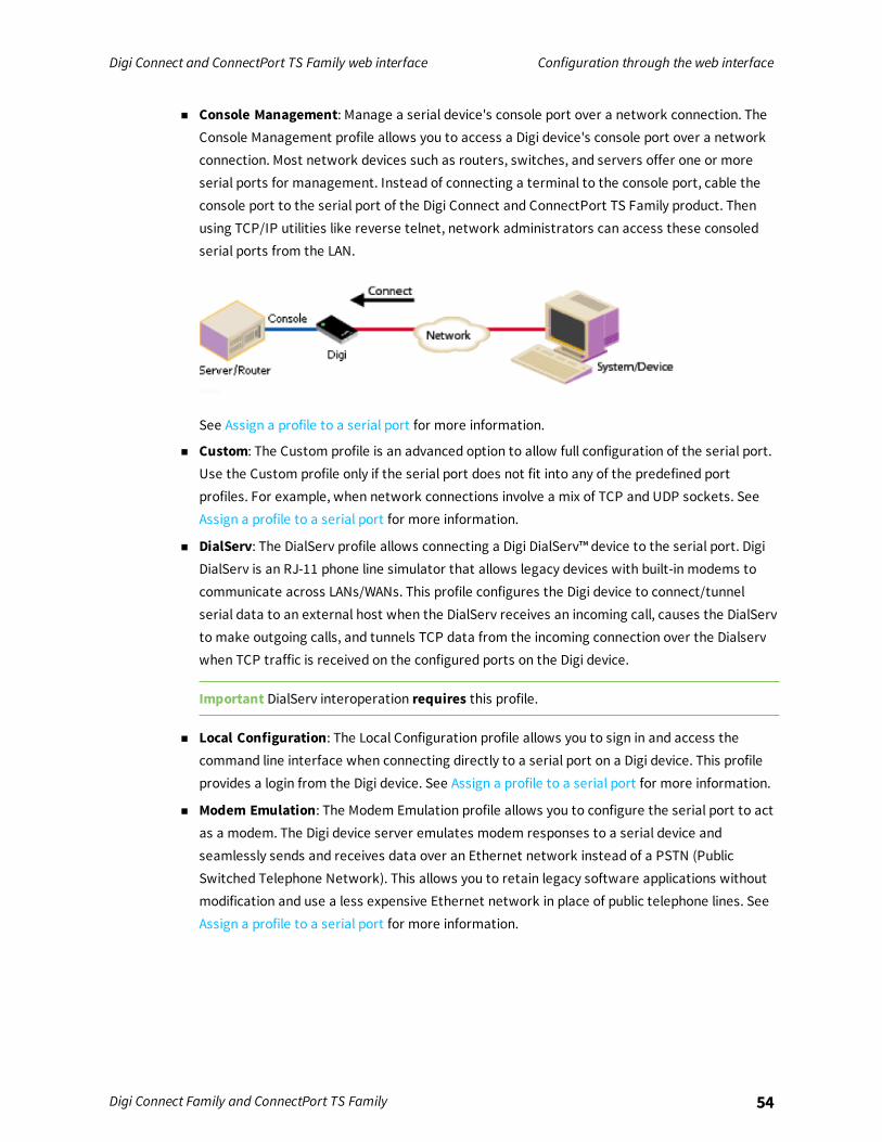
Digi Connect and ConnectPort TS Family web interface Configuration through the web interface
Digi Connect Family and ConnectPort TS Family 54
n Console Management: Manage a serial device's console port over a network connection. TheConsole Management profile allows you to access a Digi device's console port over a networkconnection. Most network devices such as routers, switches, and servers offer one or moreserial ports for management. Instead of connecting a terminal to the console port, cable theconsole port to the serial port of the Digi Connect and ConnectPort TS Family product. Thenusing TCP/IP utilities like reverse telnet, network administrators can access these consoledserial ports from the LAN.
See Assign a profile to a serial port for more information.
n Custom: The Custom profile is an advanced option to allow full configuration of the serial port.Use the Custom profile only if the serial port does not fit into any of the predefined portprofiles. For example, when network connections involve a mix of TCP and UDP sockets. SeeAssign a profile to a serial port for more information.
n DialServ: The DialServ profile allows connecting a Digi DialServ™ device to the serial port. DigiDialServ is an RJ-11 phone line simulator that allows legacy devices with built-in modems tocommunicate across LANs/WANs. This profile configures the Digi device to connect/tunnelserial data to an external host when the DialServ receives an incoming call, causes the DialServto make outgoing calls, and tunnels TCP data from the incoming connection over the Dialservwhen TCP traffic is received on the configured ports on the Digi device.
Important DialServ interoperation requires this profile.
n Local Configuration: The Local Configuration profile allows you to sign in and access thecommand line interface when connecting directly to a serial port on a Digi device. This profileprovides a login from the Digi device. See Assign a profile to a serial port for more information.
n Modem Emulation: The Modem Emulation profile allows you to configure the serial port to actas a modem. The Digi device server emulates modem responses to a serial device andseamlessly sends and receives data over an Ethernet network instead of a PSTN (PublicSwitched Telephone Network). This allows you to retain legacy software applications withoutmodification and use a less expensive Ethernet network in place of public telephone lines. SeeAssign a profile to a serial port for more information.

Digi Connect and ConnectPort TS Family web interface Configuration through the web interface
Digi Connect Family and ConnectPort TS Family 55
n RealPort: Use RealPort to map a COM or TTY port to this serial port of your Digi device. TheCOM/TTY port appears and behaves as a local port to the PC or server. RealPort is also knownas COM Port Redirection. See Assign a profile to a serial port for more information. Refer to theRealPort Setup Guide for instructions on installing and configuring the RealPort driver on yourPC or server.
When you configure a RealPort profile, the Digi Connect and ConnectPort TS Family productrelinquishes control of the serial port to the host that has the RealPort driver installed. Thecomputer applications send data to this virtual COM or TTY port and the RealPort driver sendsthe data across the network to the corresponding serial port on the Digi Connect andConnectPort TS Family product.
The network is transparent to both the application and the serial device.
Important Install and configure the RealPort software on each computer that uses RealPortports. You can download and install the RealPort software from the Digi Support site. SeeAssign a profile to a serial port for installation instructions. You need to configure the RealPortsoftware with the IP address of the Digi Connect and ConnectPort TS Family product.
n Serial Bridge: The Serial Bridge Profile configures one side of a serial bridge. A bridge connectstwo serial devices over the network as if they were connected with a serial cable. This is alsoreferred to as serial tunneling. Each serial device is connected to the serial port of a Digi deviceserver. You must configure one Digi device as the client and the other Digi device as the server.
This profile configures each side of the bridge separately.
See Assign a profile to a serial port for more information.

Digi Connect and ConnectPort TS Family web interface Configuration through the web interface
Digi Connect Family and ConnectPort TS Family 56
n TCP Sockets: Auto-Connect (TCP client) to another host on the network or allow incomingconnections on this serial port (TCP server). The TCP Sockets profile allows serial devices tocommunicate over a TCP network. The TCP server allows other network devices to initiate aTCP connection to the serial device attached to the serial port of the Digi Connect andConnectPort TS Family product. The TCP client will establish a TCP connection to a defined IPaddress and port number.
For more information about the TCP Sockets, see the following:
l Automatic TCP connections (Automatic Connection)
l RFC 2217
l TCP and UDP network port numbering conventions
See Assign a profile to a serial port for more information about assigning a profile.
n UDP Sockets: Allows the automatic distribution of serial data from one host to many devices atthe same time. The UDP Sockets profile allows serial devices to communicate using UDP. TheUDP Server configuration allows the serial port to receive data from one or more systems ordevices on the network. See Assign a profile to a serial port for more information.
The UDP Client configuration allows the automatic distribution of serial data from one host tomany devices at the same time using UDP sockets.
The port numbering conventions shown in the TCP Sockets Profile also apply to UDP sockets.
Not all port profiles are supported in all products. Supported port profiles varies by Digi Connect andConnectPort TS Family model. If a profile listed in this description is not available on the page, it is notsupported in the Digi Connect and ConnectPort TS Family product.If you selected a port profile, the port number associated with the port profile appears at the top ofthe page. You can change or retain the profile and adjust individual settings.Everything displayed on the Serial Ports Configuration page between Port Profile Settings and thelinks to the Basic Serial Settings and Advanced Serial Settings depends on the selected port profile.
Assign a profile to a serial portTo assign a profile to a serial port:

Digi Connect and ConnectPort TS Family web interface Configuration through the web interface
Digi Connect Family and ConnectPort TS Family 57
1. Select Configuration > Serial Ports.
2. Click a port number from the Port column.
3. Click Change Profile.
4. On the Select Port Profile page, select a port profile option and then click Apply.

Digi Connect and ConnectPort TS Family web interface Configuration through the web interface
Digi Connect Family and ConnectPort TS Family 58
5. Complete the steps based on the selected profile option:
n Console Management: Most network devices such as routers, switches, and serversoffer one or more serial ports for management. Instead of connecting a terminal to theconsole port, cable the console port to the serial port of your Digi device server. Thenusing TCP/IP utilities like reverse telnet, network administrators can access theseconsoled serial ports from the LAN.
a. Record the TCP (or SSH) port number listed under TCP Server Settings. Youwill need the TCP port number when configuring an application or devicethat accesses the serial port from the network.
b. To log inbound serial data, click Advanced Serial Settings, select Enableport logging, and then click Apply.
c. Click Basic Serial Settings, complete the fields to match the settings of theattached serial device, and then click Apply.
Note Configure the application or device that initiates communication to the serial portfrom the network with the following information:l IP address of this Digi device server.
l TCP or (SSH) port number for the serial port recorded above in Step a.
n Local Configuration (Console Port): Click Basic Serial Settings, complete the fields tomatch the settings of the attached serial device or terminal, and then click Apply.
n Custom: Complete the fields under Serial Port Configuration and then click Apply.
n Modem Emulation: Click Basic Serial Settings, complete the fields to match thesettings of the attached serial device and then click Apply.
Modem emulation enables a system administrator to configure the serial port to act asa modem. The Digi device server emulates modem responses to a serial device andseamlessly sends and receives data over an Ethernet network instead of a PSTN (PublicSwitched Telephone Network). The advantage for a user is the ability to retain legacysoftware applications without modification and use a less expensive Ethernet networkin place of public telephone lines.

Digi Connect and ConnectPort TS Family web interface Configuration through the web interface
Digi Connect Family and ConnectPort TS Family 59
n RealPort: COM port redirection is provided with the RealPort software installed on yournetwork-based computer. RealPort creates a virtual COM port on your computer. Whenyour computer applications send data to this virtual COM or TTY port, RealPort sendsthe data across the network to the Digi device server. The Digi device server routes thedata to the serial device connected to its serial port. The network is transparent to boththe application and the serial device.
Prerequisite RealPort software must be installed on each computer that you want toconnect to. See Install RealPort software for more information.
RealPort will set the serial port settings as directed by the computer application, sothere is no need to modify the Basic Serial Port Settings.
n Serial Bridge: A bridge connects two serial devices over the network as if they wereconnected with a serial cable. This is also referred to as serial tunneling. Each serialdevice is connected to the serial port of a Digi device server. Configure one Digi deviceas the TCP server and the other Digi device as the TCP client. Once you establish aconnection between the two Digi devices the communication is bi-directional.
To assign a Serial Bridge (Serial Tunneling) to a serial port on a Digi device acting as theTCP client (which initiates the connection to the TCP server):
a. Select Initiate serial bridge to the following device and provide thefollowing information:
l Type the IP Address of the other Digi device server.
l In the TCP Port field, type the Raw TCP port number for the destinationserial port. If the serial port is the first or only port on the device server,the value is 2101.
b. Click Apply to save the configuration.
c. Click Basic Serial Settings, complete the fields to match the settings of theattached serial device and then click Apply.
Follow the same steps to configure the Digi device server on the other side of thebridge, with the following exceptions:l Select Allow other devices to initiate serial bridge. The default TCP Port rarely
needs to be changed.
l Clear the Initiate serial bridge to the following device check box.

Digi Connect and ConnectPort TS Family web interface Configuration through the web interface
Digi Connect Family and ConnectPort TS Family 60
n TCP Sockets for TCP client (Automatic Connection): In a TCP client configuration, theDigi device server automatically establishes a TCP connection to an application ornetwork device. See Automatic TCP connections (Automatic Connection) for moreinformation.
To assign a TCP Client (Automatic Connection) profile to a serial port:a. Under TCP Client Settings, select the Automatically establish
TCP connections check box.
b. Select the Connect option that describes when the TCP connection will beinitiated.
c. Type the IP address or DNS name of the destination server in the Server(name or IP) field.
d. Select one of the following options from the Service drop-down list:l Raw TCP
l Rlogin
l Secure Sockets
l Telnet
l SSH

Digi Connect and ConnectPort TS Family web interface Configuration through the web interface
Digi Connect Family and ConnectPort TS Family 61
e. Specify the destination TCP port number in the TCP Port field. The portnumber depends on the conventions used on the remote server or device.The following table provides the common TCP port number conventions.
Connection Service Common TCP Port Number
Telnet 23
Rlogin 513
Reverse Telnet to the port of theDigi device serverThe format for this port number isas follows:
20<serial port number>
Replace <serial port number> withthe Digi serial port number. Forexample, 2001 applies to serial port1, 2010 applies to serial port 10, and2016 applies to serial port 16.
2001
Raw connection to the port of theDigi device serverThe format for this port number isas follows:
21<serial port number>
Replace <serial port number> withthe Digi serial port number. Forexample, 2101 applies to serial port1, 2110 applies to serial port 10, and2116 applies to serial port 16.
2101
f. Click Apply to save the configuration.
g. Click Basic Serial Settings, complete the fields to match the settings of theattached serial device or terminal, and then click Apply.

Digi Connect and ConnectPort TS Family web interface Configuration through the web interface
Digi Connect Family and ConnectPort TS Family 62
n TCP Sockets for TCP server: A TCP Server configuration allows other network devicesto initiate a TCP connection to the serial device attached to a serial port of the Digidevice server. This is also referred to as reverse telnet, console management or devicemanagement.
a. Record the TCP (or SSH) port number listed under TCP Server Settings. Youwill need the TCP port number when configuring an application or devicethat accesses the serial port from the network.
b. Click Basic Serial Settings, complete the fields to match the settings of theattached serial device or terminal, and then click Apply.
Note Configure the application or device that initiates communication to the serial portfrom the network with the following information:l IP address of this Digi device server.
l TCP or (SSH) port number for the serial port recorded above in Step a.
n UDP Sockets for UDP client (data distribution): UDP client configuration allows theautomatic distribution of serial data from one host to many devices at the same timeusing UDP sockets. This is also referred to this as UDP Multicast.
a. Under UDP Client Settings, provide the following information for each UDPdestination:l A description of the destination.
l The destination IP Address or DNS name.
l The destination UDP port.
When finished, click Add.
b. Select the options that define when to send data and click Apply.
c. Click Basic Serial Settings, complete the fields to match the settings of theattached serial device or terminal, and then click Apply.
n UDP Sockets for a UDP server:a. Record the UDP port number listed under UDP Server Settings. You will
need the UDP port number when configuring an application or device thataccesses the serial port from the network.
b. Click Basic Serial Settings, complete the fields to match the settings of theattached serial device, and then click Apply.
Note Configure the application or device that initiates communication to the serial portfrom the network with the following information:l IP address of this Digi device server.
l UDP port number for the serial port recorded previously in Step a.

Digi Connect and ConnectPort TS Family web interface Configuration through the web interface
Digi Connect Family and ConnectPort TS Family 63
Automatic TCP connections (Automatic Connection)The TCP Client allows the Digi Connect and ConnectPort TS Family product to automatically establisha TCP connection to an application or a network, known as autoconnection. You can enableautoconnection through the TCP Sockets profile’s setting labeled Automatically establish TCPconnections. When you set the TCP Sockets profile, the DTR flow-control signal indicates when a TCPsocket connection has been established. You can use this information whenmonitoring the serial line.You can use it as a flow-control mechanism to determine when the Digi device connects to a remotedevice establishes communication. You can combine this mechanism with the DCD signal to close theconnection and the DSR signal to do RCI over serial. Together, you can use these signals to the Digidevice to auto connect to many devices, deterministically, on the network.
TCP and UDP network port numbering conventionsDigi devices use the following conventions for TCP and UDP network port numbering:
For this connection type... Use this Port
Telnet to the serial portThe format for this port number is as follows:
20<serial port number>
Replace <serial port number> with the Digi serialport number. For example, 2001 applies to serialport 1, 2010 applies to serial port 10, and 2016applies to serial port 16.
2001 (TCP only)
Raw connection to the serial portThe format for this port number is as follows:
21<serial port number>
Replace <serial port number> with the Digi serialport number. For example, 2101 applies to serialport 1, 2110 applies to serial port 10, and 2116applies to serial port 16.
2101 (TCP and UDP)
The application or Digi Connect and ConnectPort TS Family device that initiates communication mustuse these network ports numbers. If you cannot configure the application or Digi Connect andConnectPort TS Family product to use these network port numbers, change the network port on theDigi Connect and ConnectPort TS Family product.
RFC 2217Use the RFC 2217 protocol to access serial devices over the network. RFC 2217 implementationsenable applications to set the parameters of remote serial ports (for example, baud rate or flowcontrol), detect line signal changes, as well as receive and transmit data. The configurationinformation provided in this section applies to Digi device functioning as RFC 2217 servers. If using theRFC 2217 protocol, do not modify the port settings from the defaults. If the port settings have beenchanged, restore the factory default settings (see Factory Default Settings). No additionalconfiguration is required.
Digi Connect and ConnectPort TS Family web interface Configuration through the web interface
Digi Connect Family and ConnectPort TS Family 64
Industrial automation profileThis port profile is available in Digi devices that support Industrial Automation (IA) and the Modbusprotocol. It has serial port settings appropriate for the Digi Connect WAN IA’s use in IA applications. Itallows you to control andmonitor various IA devices and PLCs. Serial ports for Digi Connect WAN IAdevices are set to use this port profile by default. The default settings for the Digi Connect WAN IA andin this port profile is sufficient for most IA applications. If you need to change the settings from thedefaults, use the “set ia” command, documented in the Digi Connect® Family Command Reference.
Basic serial settingsThe basic serial port settings must match the serial settings of the connected device. If you do notknow these settings consult the documentation that came with your serial device. These serialsettings may be documented as 9600 8N1, which means that the device is using a baud rate of 9600bits per second, 8 data bits, no parity, and 1 stop bit.When using RealPort (COM port redirection) these settings are supplied by applications running on thePC or server, and the default values on your Digi device server do not need to be changed.The possible settings are as follows:
n Description: Specifies an optional character string for the port which can be used to identifythe device connected to the port.
n Baud Rate: Select the baud rate value for the serial device.
n Data Bits: Select the data bits value for the serial device.
n Parity: Select the parity for the serial device.
n Stop Bits: Select the stop bit value for the serial device.
n Flow Control: Select the flow control value for the serial device.
Multiple Electrical Interface (MEI) serial settingsFor Digi devices with Multiple Electrical Interface (MEI) switch-setting capability, these settingsconfigure MEI settings on a per-port basis, and display the current MEI settings for the port. MEIsettings include the type of electrical interface (EIA-232 or EIA-485), the number of differential wiresused for communication, and whether termination and biasing resistors are used.
n EIA-232: Sets the electrical interface for the serial port to EIA-232. This is the default setting.This interface uses independent wires to transmit and receive data, which allows data to besent and received between devices simultaneously.

Digi Connect and ConnectPort TS Family web interface Configuration through the web interface
Digi Connect Family and ConnectPort TS Family 65
n EIA-422/EIA-485: The serial port uses electrical interface EIA-485. You can use this mode forEIA-422 connections. This interface uses two wires to both transmit and receive data. Thisinterface also allows for multiple transmitters and receivers to be easily connected together.
For EIA-485 mode, there are several additional settings:
l 2 wires | 4 wires: Selects the number of differential wires used for communication andimplicitly determines the duplex of the connection.
2 wires: The serial port operates in two-wire mode. This mode is a half-duplex connectionwith shared transmit and receive wires.
4 wires: The serial port operates in four-wire mode. This mode is a full-duplex connectionwith independent transmit and receive pairs.
The default is 4 wires.
l Enable termination: Determines whether termination and biasing resistors are usedacross the lines. If enabled, termination and biasing resistors are enabled across the lines.Enable termination if the terminal/server port is an endpoint node on the 485 network. Usebiasing in at least one unit in a two-wire environment. If disabled, termination and biasingresistors are disabled across the lines. The default is disabled.
Advanced serial settingsUse Advanced Serial Settings to configure the serial interface and the access to the serial interface.The default settings work in most situations.
Serial settingsn Enable Port Logging: Port logging allows you to save serial data to the memory of the Digi
device server. Once enabled, the port log can be viewed by selecting Port Logs on the SerialPort Management page (Management > Serial Ports). Port Logging is enabled in the CLI viathe set buffer command.
n Log Size: The size in kilobytes of the memory buffer used to save serial data when port loggingis enabled.
n Automatic backup: The port data is stored to specified location automatically.
n Unlimited automatic backup size: When enabled, the automatic backup size is not limited.
n Automatic backup size: This option defines the amount of the log to backup at a time.
n Enable SYSLOG service: The port data can be stored to the SYSLOG server in addition to theport log storage location at the same time.
n Enable RTS Toggle:When enabled, the Digi device asserts RTS (Request To Send) whensending data on the serial port.

Digi Connect and ConnectPort TS Family web interface Configuration through the web interface
Digi Connect Family and ConnectPort TS Family 66
n Enable RCI over Serial (DSR): This choice allows configure the Digi Connect device throughthe serial port using the RCI protocol. See the RCI specification in the Digi Connect IntegrationKit for further details.
RCI over Serial uses the DSR (Data Set Ready) serial signal. Verify that the serial port is notconfigured for autoconnect, modem emulation, or any other application which is dependent onDSR state changes.
n Enable alternate pinout (altpin): Enables or disables the altpin option, which swaps DCDwith DSR so that you can use eight-wire RJ-45 cables with modems. By default, the altpin isdisabled.
TCP SettingsThese TCP Settings are available only when you configure the current port with the ConsoleManagement, Custom, or TCP Sockets profile.
n Send Socket ID: Include an optional identifier string with the data sent over the network.
The Socket ID can be 1 to 256 ASCII characters. Enter non-printable characters asfollows:
CharacterKeySequence
backspace \b
formfeed \f
tab \t
line feed \n
return \r
backslash \\
hexadecimalvalues
\xhh
n Send data only under any of the following conditions: Enable if you need to specify theconditions when the Digi device server will send the data read from the serial port to the TCPdestination.

Digi Connect and ConnectPort TS Family web interface Configuration through the web interface
Digi Connect Family and ConnectPort TS Family 67
n Send when data is present on the serial line: Send the data to the network destinationswhen a string of characters is detected in the serial data. To enter non-printable characters,use these key sequences:
CharacterKeySequence
hexadecimalvalues
\xhh
tab \t
line feed \n
backslash \\
n Match string: A 1 to 4 character string. This is usually the newline character sequence but canalso be a custom string of 1 to 4 characters.
n Strip match string before sending: Search for the string specified in the Match String fieldbefore sending the data and strip the string from the string from the data before it is sent tothe destination.
n Send after the following number of idle milliseconds: Send the data after the specifiednumber of milliseconds have passed with no data received on the serial port.
n Send after the following number of bytes: Send the data after the specified number ofbytes have been received on the serial ports.
n Close connection after the following number of idle seconds: Enable to close an idleconnection. Use the Timeout field to enter the number of seconds that the connection will beidle before it is closed. This can be 1 to 65000 seconds.
n Close connection when DCD goes low: When selected, the connection will be closed when theDCD (Data Carrier Detected) signal goes low.
Note If you are using 8-wire cabling, you must apply the altpin for DCD functionality.
n Close connection when DSR goes low: When selected, the connection will be closed when theDSR (Data Set Ready) signal goes low.
UDP settingsThese UDP Settings are available only when the current port is configured with the Consolemanagement, the UDP Sockets, or the Custom Profile.
n Send Socket ID: Include an optional identifier string with the data sent over the network.
The Socket ID can be 1 to 256 ASCII characters. Enter non-printable characters asfollows:

Digi Connect and ConnectPort TS Family web interface Configuration through the web interface
Digi Connect Family and ConnectPort TS Family 68
CharacterKeySequence
backspace \b
formfeed \f
tab \t
line feed \n
return \r
backslash \\
hexadecimalvalues
\xhh
Display current serial port settingsTo display the current serial port settings for a Digi device, type display techsupport from thecommand line interface.
GPIO pinsThis section applies only to embedded products. All Digi Connect Family embedded devices haveseveral General Purpose IO (GPIO) pins. In normal operation, GPIO pins are used for the serial signalsCTS, DCD, DSR, DTR, and RTS. On Digi Connect EM andWi-EM, both sets of RXD/TXD signals are alsoconfigured. You can use these GPIO pins for either standard serial communication signaling or a user-defined purpose, such as when a significant event occurs in the device. In the latter case, you canconfigure the Digi device so that when an event occurs, an alarm is sent as an email message to anadministrator or technician, or as an SNMP trap. The number of GPIO pins varies by device. DigiConnect ME andWi-ME devices have five GPIO pins, while Digi Connect EM andWi-EM devices havenine GPIO pins. You can view the configuration and current state of GPIO pins through the webinterface or by issuing commands from the command line.
GPIO pin settingsThe GPIO Configuration page configures GPIO pin settings. You can configure GPIO pins configured forone of three modes: serial, input, and output.
n Serial: Use the GPIO pin for standard serial communication signaling. Each pin maps to adifferent serial signal: DCD, CTS, DSR, and so on. The following table lists the default serialsettings for the GPIO pins on a Digi device. Depending on the device, there are five or nine pins.
Pin Number Default Serial Signal Signal Direction
GPIO 1 DCD Input
GPIO 2 CTS Input
GPIO 3 DSR Input
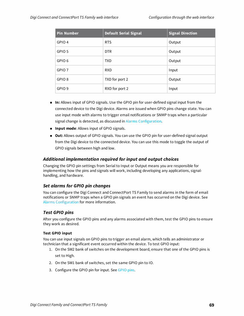
Digi Connect and ConnectPort TS Family web interface Configuration through the web interface
Digi Connect Family and ConnectPort TS Family 69
Pin Number Default Serial Signal Signal Direction
GPIO 4 RTS Output
GPIO 5 DTR Output
GPIO 6 TXD Output
GPIO 7 RXD Input
GPIO 8 TXD for port 2 Output
GPIO 9 RXD for port 2 Input
n In: Allows input of GPIO signals. Use the GPIO pin for user-defined signal input from theconnected device to the Digi device. Alarms are issued when GPIO pins change state. You canuse input mode with alarms to trigger email notifications or SNMP traps when a particularsignal change is detected, as discussed in Alarms Configuration.
n Input mode: Allows input of GPIO signals.
n Out: Allows output of GPIO signals. You can use the GPIO pin for user-defined signal outputfrom the Digi device to the connected device. You can use this mode to toggle the output ofGPIO signals between high and low.
Additional implementation required for input and output choicesChanging the GPIO pin settings from Serial to Input or Output means you are responsible forimplementing how the pins and signals will work, including developing any applications, signal-handling, and hardware.
Set alarms for GPIO pin changesYou can configure the Digi Connect and ConnectPort TS Family to send alarms in the form of emailnotifications or SNMP traps when a GPIO pin signals an event has occurred on the Digi device. SeeAlarms Configuration for more information.
Test GPIO pinsAfter you configure the GPIO pins and any alarms associated with them, test the GPIO pins to ensurethey work as desired.
Test GPIO inputYou can use input signals on GPIO pins to trigger an email alarm, which tells an administrator ortechnician that a significant event occurred within the device. To test GPIO input:
1. On the SW2 bank of switches on the development board, ensure that one of the GPIO pins isset to High.
2. On the SW1 bank of switches, set the same GPIO pin to IO.
3. Configure the GPIO pin for input. See GPIO pins.

Digi Connect and ConnectPort TS Family web interface Configuration through the web interface
Digi Connect Family and ConnectPort TS Family 70
4. Configure an email alarm for the GPIO pin. See Alarms Configuration.
5. Toggle the SW2 switch several times to generate several email alarms.
Test GPIO outputTo test GPIO output, you must send a GPIO signal from the configuration application that turns on anLED on the development board.
1. On the SW2 bank of switches on the development board, ensure that one of the GPIO pins isset to High.
2. On the SW1 bank of switches, set the same GPIO pin to IO.
3. From the Digi device's web interface, click GPIO . On the GPIO page, configure one or moreGPIO pins for output. See GPIO pins for details.
4. Under Administration, click System Information.
5. On the System Information page, click GPIO.
6. Choose Asserted to raise the signal, and then click Set Pins. An LED on the development boardis turned on.
Note This process does not configure the Digi device. Settings are not saved. If the modulereboots, perform steps 2 and 3 again.
Alarms ConfigurationUse the Alarms Configuration page to configure device alarms and displaying alarm settings. Devicealarms send email messages or SNMP traps when certain device events occur. These device eventsinclude changes in GPIO signals, data patterns detected in the data stream
Alarm notification settingsUse the Alarm Notification Settings page to configure the following:
n Enable alarm notifications: Enables or disables all alarm processing for the Digi device.
n Send all alarms to the Remote Management server: enables or disables sending of alarmnotifications to a server that handles remote management of devices, such as RemoteManager.
Enabling this setting sends all alarm notifications to Remote Manager. Enable this option if theDigi device is managed by a remote management server, such as Remote Manager. Enablingthis option is useful because it allows all alarms to be monitored from one location. Enablingthis option also allows Digi devices to send alarms to clients that would otherwise beunreachable from the Digi device, either because the Digi device is behind a firewall or not onthe same network as the alarm destination.
When you disable this setting alarm notifications are not sent to Remote Manager. Disable thissetting if devices are not managed by a Remote Manager server or if alarms are sent from thedevice. For example, an SNMP trap destination is local to the device, not Remote Manager.
Digi Connect and ConnectPort TS Family web interface Configuration through the web interface
Digi Connect Family and ConnectPort TS Family 71
n Mail Server Address (SMTP): Specifies the IP address of the SMTP mail server. Ask yournetwork administrator for this IP address.
n From: Specifies the text that used in the “From:” field for all alarms that are sent as emails.
Alarm list and statusThe Alarm Conditions page lists all of the alarms. You can configure up to 32 alarms for a Digi device,and you can individually enable and disable these alarms.The alarm list displays the current status of each alarm. You can use this list to view alarm status at aglance, then view more details for each alarm as needed.
n Enable: The check box indicates whether the alarm is currently enabled or disabled.
n Alarm: The number of the alarm.
n Status: The current status of the alarm, which is either enabled or disabled.
n Type: The basis for the alarm; whether it is based on GPIO pin state changes or serial datapattern matching.
n Trigger: The conditions that trigger the alarm.
n SNMP Trap: Indicates whether the alarm is sent as an SNMP trap.l If the SNMP Trap field is disabled, and the Send To field has a value, the alarm is sent as an
email message only.
l If the SNMP Trap field is enabled and the Send To field is blank, the alarm is sent as anSNMP trap only.
l If the SNMP Trap field is enabled, and a value is specified in the Send To field, that meansthe alarm is sent both as an email and as an SNMP trap.
n Send To: The email address to which the alarm is sent.
n Email Subject: Text to include in the Subject line of alarms sent as email messages.
Alarm ConditionsUse the Alarm Conditions page to specify the conditions on which the alarm is based, such as GPIO pinstate changes, serial data pattern matching, signal strength (RSSI), or data usage. Alarm conditionsinclude:
n Send alarms based on GPIO pin states: Click this radio button to specify that this alarm issent when the specified GPIO pin states are detected. Then specify the following:
l Pins: An alarm is sent when the specified combination of pin states is detected.
High - pin is asserted.
Low - pin is not asserted.
Ignore - pin state is ignored.
l Alarm recurrence time: Defines how often to send a new alarm. For example, if the alarmrecurrence time is 10 seconds then even if the pin states are detected 5 times within a 10second period only one alarm will be sent.
Digi Connect and ConnectPort TS Family web interface Configuration through the web interface
Digi Connect Family and ConnectPort TS Family 72
l Send reminders while GPIO pins remain in this state: If enabled, reminders will be sentif the pins remain in the defined state for an extended period of time.
l Every: The number of seconds the pins must remain in the defined state for a reminder tobe sent.
n Send alarms based on serial data pattern matching: Click this radio button to specify thatthis alarm is sent when the specified serial data pattern is detected. Then specify the following:l Serial Port: The serial port to monitor for the data pattern. This field appears for devices
where more than one serial port is available.
l Pattern:When the serial port receives this data pattern it sends an alarm. You can includespecial characters such as carriage return carriage return (\r) and new line (\n) in the datapattern.
Alarm DestinationsUse the Alarm Destinations page to define how alarm notifications are sent, either as an emailmessage or an SNMP trap, or both, and where the alarm notification is sent.
n Send E-mail to the following recipients when alarm occurs: Enable sending the alarm as anemail message. Then specify the following information:l To: The email address to which this alarm notification email message will be sent.
l CC: The email address to which a copy of this alarm notification email message will be sent(optional).
l Priority: The priority of the alarm notification email message.
l Subject: The text to be included in the Subject: line of the alarm-notification email.
n Send SNMP trap to the following destination when alarm occurs: Specifies whether tosend the alarm as an SNMP trap. To send alarms as SNMP traps, you must set the Alarm Typeto snmptrap and specify the IP address of the destination for the SNMP traps in the SNMPsettings (Configuration > System > Simple Network Management Protocol). See SimpleNetwork Management Protocol (SNMP) Settings. That destination IP address appears belowthe “Send alarm to SNMP destination” check box. You can also specify a secondary or backupSNMP destination.
To configure an alarm notification to be sent as both an email message and an SNMP trap:1. Select both Send E-Mail and Send SNMP trap check boxes.
2. Click Apply to apply changes to alarm settings and return to the Alarms Configuration page.
Configure alarm conditionsTo configure an alarm:
1. Select Configuration > Alarms.
2. To enable or disable an alarm, select or clear the Enable check box next to the alarm.
3. Click the alarm under the Alarm column that you want to configure.

Digi Connect and ConnectPort TS Family web interface Configuration through the web interface
Digi Connect Family and ConnectPort TS Family 73
4. Configure the fields in the following sections:n Alarm Conditions: These condition specify the conditions on which the alarm is based,
such as serial data pattern matching or data usage.
n Alarm Destinations: These conditions specify how the alarm is sent, either as an emailmessage or an SNMP trap, or both, and where the alarm is sent.
5. Click Apply to save your changes.
System ConfigurationUse the System Configuration page to configure device identity and description information, date andtime settings, and settings for Simple Network Management Protocol (SNMP).
Device Identity SettingsUse the Device Identity Settings page to create a description of the Digi Connect and ConnectPort TSFamily product’s name, contact, and location. You can use this information to identify a specific Digidevice product when working with a large number of devices in multiple locations.
n Description: The network name assigned to the Digi device.
n Contact: The SNMP contact person (often the network administrator).
n Location: A text description of the physical location of the Digi device.
n Device ID: A text description of the device ID used to identify the device (for example, MAC orIP address).
Simple Network Management Protocol (SNMP) SettingsUse the Simple Network Management Protocol (SNMP) Settings page to manage andmonitornetwork devices. You can configure Digi Connect and ConnectPort TS Family devices to use SNMPfeatures, or you can disable SNMP for security reasons. For additional information, see SimpleNetwork Management Protocol (SNMP).
n Enable Simple Network Management Protocol (SNMP): This check box enables or disablesuse of SNMP.l The Public community and Private community fields specify passwords required to get
or set SNMP-managed objects. Changing public and private community names from theirdefaults is recommended to prevent unauthorized access to the device.
l Public community: The password required to get SNMP-managed objects. The default ispublic.
l Private community: The password required to set SNMP-managed objects. The default isprivate.
l Allow SNMP clients to set device settings through SNMP: This check box enables ordisables the capability for users to issue SNMP set commands uses use of SNMP read-onlyfor the Digi device.

Digi Connect and ConnectPort TS Family web interface Configuration through the web interface
Digi Connect Family and ConnectPort TS Family 74
n Enable Simple Network Management Protocol (SNMP) traps: Enables or disables thegeneration of SNMP traps.l Trap Destinations: Provide the IP address or fully qualified domain name (FQDN) of the
system where the SNMP agent sends traps. The primary destination is required. Thesecondary destination is optional.
l Primary/Secondary: The IP address of the system to which the SNMP agent sends traps.To enable any of the traps, you must specify a non-zero value. The primary destination isrequired. The secondary destination is optional. If your Digi devices supports alarms, youmust complete this field in order to send alarms in the form of SNMP traps. See AlarmsConfiguration.
You can use the following SNMP trap check boxes:l Generate authentication failure traps: The SNMP agent will send SNMP authentication
traps when there are authentication failures.
l Generate login traps: The SNMP agent sends SNMP login traps on login attempts.
l Generate cold start traps: The SNMP agent sends traps on cold starts of the Digi device.
l Generate link up traps: The SNMP agent sends link up traps when network connectionsare established.
Date and Time SettingsUse the Date and Time Settings page to set the Coordinated Universal Time (UTC) and/or systemtime and date on a device, or set the offset from UTC for the Digi device's system time.
Set the date and timeTo set the date and time, click the Set button to configure the hours, minutes, seconds, month, day,and year on the device.If offset is set to 00:00, the device's system time and UTC are the same. Setting time and date with anoffset of 00:00 results in both UTC and system time being set to the specified value. If offset is not00:00, setting time sets the system time to the specified value and UTC is adjusted accordingly.
Offset from UTCSpecifies the offset from UTC for this device. Offset can range from -12 hours to 14 hours. Very rarely,a time zone can also have an offset in minutes (15, 30, or 45). You can use this value to modify the timeand date (generally expected to be UTC) to compensate for time zones and daylight savings time.Wikipedia provides a list of time zone offsets at: https://en.wikipedia.org/wiki/Lists_of_time_zonesOn a device with no real-time clock (RTC) and no configured time source, time and date arecompletely local to the device and have limited usefulness since they are not persistent overreboots/power-cycles.On a device with a real-time clock and no configured clock source, time and date are also local to thedevice but they are meaningful because they are persistent. The offset option could be useful inadjusting for daylight savings time. Setting the date and time to standard time and setting offset to 1whenever daylight savings time is in effect would serve that purpose.On a device with a configured clock source, time and date received from a clock source is expected tobe UTC. For users with several devices in different time zones, keeping offset=00:00 might be usefulfor comparing logs or traces from different devices, since all would be using UTC.

Digi Connect and ConnectPort TS Family web interface Configuration through the web interface
Digi Connect Family and ConnectPort TS Family 75
Time source settingsThe time source settings configure access to up to five external time sources that you can use to setandmaintain time on the device.
n Type: Specifies the type of time source for this entry.l sntp server: The device uses its SNTP client to poll the NTP/SNTP server, specified by the
FQDN, for time.
l cellular: The device polls the cellular service for time.
n Interval: Specifies the interval in seconds between polls of a time source. Interval can rangefrom 1 second to 31536000 seconds. If more than one time source is specified, time sourceswith shorter intervals have greater influence on the device's time than do sources with longerintervals.
n FQDN: Specifies the fully-qualified domain name or IP address for the time source. Use FQDNonly if the time source is SNTP.
The only time source that is guaranteed to be present on all products at all times is the system clock.It counts uptime and displays system time as the Unix Epoch (00:00:00 on January 1, 1970) plusuptime. Any source that is not the system clock is considered an external source. This includes theRTC.Devices which have an RTC but have no external time sources configured will display system time asthe Unix Epoch plus the time since power was initially applied to the device until system time is setmanually. You can manually set system time via the CLI, Web UI, and so on. Once system time is setmanually, the RTC will continue to maintain system time but, due to variations in the accuracy of theRTC, system time can diverge from external time.Specifying an external time source allows the device to compare its system time to the time reportedby the configured time sources and appropriate adjustments to system time. This allows system timeto stay consistent over long durations.The polling interval for an external source establishes its priority relative to other sources; the moresamples taken from a time source, the greater influence that time source has on system time.Any time adjustment will update the RTC automatically. All time sources are assumed to be UTC.
Time Source Global settingsUse the Time Source Global settings to configure the global settings that control time sourcemanagement.
n Time Adjustment Threshold: A value in seconds that defines a range around the current timevalue maintained by the device. If the Digi device receives a time update from a best (smallestvalue) ranking time source and the new time is within that range, the Digi device's time is notchanged. However, if the new time falls outside the defined threshold range, the Digi device'stime is updated immediately using the new time value.
The Time Adjustment Threshold value can range from 0 to 300 seconds. For example, if theconfigured threshold is 60 seconds, the Digi device's time will be updated using a new timevalue that is 60 seconds or more different than the Digi device's current time value. If the newtime value differs from the Digi device's current time by less than 60 seconds, the Digi device'stime is not updated using that new time.
Digi Connect and ConnectPort TS Family web interface Configuration through the web interface
Digi Connect Family and ConnectPort TS Family 76
n Enable Lost Time Source Recovery: If multiple external time sources are available andconfigured in the Time Source Settings, normally only the best-ranking (smallest value) source(s) will be used to maintain the Digi device's time. If the best-ranking source stops reportingnew time values, it is considered “lost”.
Enabling Lost Time Source Recovery allows the Digi device to consult one or more worse-ranking (higher value) time sources in an effort to obtain a fresh time value. This prevents thebest-ranking configured time source from blocking time updates if that source stops providingacceptable time samples.
The interval of time that must pass for Lost Time Source Recovery to begin varies according tothe best ranking time source that is reporting a value. For a time source of type “sntp server”,the missing sample update interval is three NTP/SNTP intervals configured for that timesource, plus one minute. For a time source other than “sntp server”, the missing sampleupdate interval is 61 minutes. You cannot configure these interval values.
Use the Time Adjustment Threshold to limit the amount of drift that will be tolerated before the Digidevice's time is updated using a new sample. You should select an appropriate value withconsideration for the reliability of the time sample sources.In the case of NTP/SNTP server sources, you should also consider the latency, round-trip timing, andreliability of the network connection (between the Digi device and the server).If the communications path between the Digi device and server involves a cellular networkconnection, you should consider the performance and behavior characteristics of the cellular network.In a cellular network, intermittent packet delays are possible in either the transmit or receivedirection (or both). Frequently these delays are asymmetric, such that the delay is greater in onedirection than in the other.In such conditions, the round-trip timing (of the request/reply) skews the time sample adjustment todetermine the time value to use for the device. Therefore configuring an aggressively small (short)threshold value may cause the device to adjust its time frequently and unnecessarily, such that thetime value “jumps” forward or backward as a consequence of asymmetric packet delays.
Remote Manager settingsThe Remote Manager configuration page sets up the connection to the Device Management remotemanagement server so the Digi device can connect to the server. Device Management allows you toconfigure andmanage Remote Manager-registered devices from remote locations.In this discussion:
n Remote Manager refers to the Digi machine-to-machine cloud-based network operatingplatform.
n Device Management refers to a web based device management application that allows a userto manage their inventory of devices.
n Remote Manager-registered device is Digi device that connects to the Remote Manager platformwhich implements the EDP protocol in order to establish andmaintain this connection.
For more information about Remote Manager, these terms, and how to remotely configure andmanage this device, please visit the Remote Manager product page and see the Remote Manager UserGuide.

Digi Connect and ConnectPort TS Family web interface Configuration through the web interface
Digi Connect Family and ConnectPort TS Family 77
Device ID requirement for the Digi deviceWhen configuring a Digi device to be a Remote Manager-registered device, you must create a DeviceID for the Digi device. The Device ID allows the Digi device to communicate with Remote Manager.By default, the Device ID is created from the MAC address of the device. The default setting is therecommended setting for the Device ID. You can configure the Device ID from the Configuration >System > Device Identity Settings page on the Digi device's web interface. See System Configurationfor more information.After you configure the device’s Device ID, you must sign in to Remote Manager and configure thesettings on the following pages:
n Connection Settings
n Short Messaging
n Advanced Settings
Connection settingsThe Connection settings configure how the Remote Manager-registered device connects to RemoteManager. These settings allow the Remote Manager-registered device and Remote Manager tocommunicates with each other.
About Remote Manager connectionsYou can choose how your Remote Manager-registered device connects to and communicates withRemote Manager: through a device-initiated Remote Manager connection or a (device-initiated) timedconnection. To illustrate how these types of connections work, the following image shows aconfiguration scenario featuring Remote Manager-registered devices communicating over a cellularnetwork.
You can specify addresses for Remote Manager-registered devices that are publicly known, or privateand dynamic, or handled through Network Address Translation (NAT). NAT reduces the need for alarge amount of publicly known IP addresses by creating a separation between publicly known andprivately known IP addresses. NAT allows a single device, such as a router, to act as an agentbetween a public network, such as the Internet or a wireless network, and a private, or local,network. This means that only one unique IP address is needed to represent an entire group ofcomputers. Addresses handled through NAT can access the rest of “the world,” but “the world”cannot access them.In a device-initiated Remote Manager connection, the Remote Manager-registered device connects tothe network, and tries to establish a connection to Remote Manager. To maintain the connection, theRemote Manager-registered device sends keep-alive messages over the connection. You can configurethe frequency in which keep-alive messages are sent. You can use device—initiated Remote Managerconnections in any cellular network, whether using public or private IP addresses, or even if using NAT.Note that your cellular/mobile provider may charge you, depending on your cellular/mobile serviceplan, when the Remote Manager-registered device sends keep-alives messages.

Digi Connect and ConnectPort TS Family web interface Configuration through the web interface
Digi Connect Family and ConnectPort TS Family 78
A server-initiated Remote Manager connection works the opposite way. Remote Manager opens a TCPconnection, and the Remote Manager-registered device must be listening for the connection fromRemote Manager to occur. An advantage of server-initiated Remote Manager connections is that youare not charged for sending the keep-alive bytes that are used in device-initiated connections. Adisadvantage is that there is no way of knowing whether the devices displayed in the RemoteManager-registered device list are offline or connected. The device list shows all the devices asdisconnected until Remote Manager does something to interact with them. In addition, you cannotuse Remote Manager connections for devices that use private IP addresses and are behind a NAT.(Server-initiated connections are not supported.)A timed connection is another form of a device-initiated connection. For a timed connection, theRemote Manager-registered device tries to connect to the Remote Manager Server at a configured,regular interval (period). If a connection to an Remote Manager Server is already established, thetimed connection will not be attempted. The next attempt for a timed connection will occur at thenext scheduled interval.
Device IP address updatesChanges to the IP address for an Remote Manager-registered device present a challenge in RemoteManager server-initiated connections, because Remote Manager needs to locate the RemoteManager-registered device by its new IP address. Remote Manager devices handle address changesby sending a device IP address update to Remote Manager. An IP address update permits RemoteManager to connect to the Remote Manager-registered device, or to dynamically update a DNS withthe IP address of the Remote Manager-registered device.
Device-Initiated Remote Manager Connection settingsn Enable Device-Initiated Remote Manager Connection: When enabled, the Remote Manager-
registered device initiates the connection to the Remote Manager.
n Remote Manager Server Address: The IP address or hostname of the Remote Managerplatform.
n Automatically reconnect to Remote Manager after being disconnectedReconnect after: When enabled, the Remote Manager-registered device automaticallyreconnects to Remote Manager after being disconnected and waiting for the specified amountof time.
Server-Initiated Remote Manager Connection settingsEnable Server-Initiated Remote Manager Connection: Configures the connection to the RemoteManager server to be initiated by Remote Manager.Enable Device IP Address updates to the following server: Enables or disables a connection toRemote Manager to inform Remote Manager of the IP address of the Remote Manager-registereddevice, known as a device IP address update. This permits Remote Manager to connect back to theRemote Manager-registered device, or to dynamically update a DNS with the IP address of theRemote Manager-registered device.Remote Manager Server Address: The IP address or hostname of the Remote Manager platform.Retry if the IP address update fails:Retry after: These options specify whether another IP address update attempt should be made aftera previous attempt failed, and how often the retry attempts should occur.

Digi Connect and ConnectPort TS Family web interface Configuration through the web interface
Digi Connect Family and ConnectPort TS Family 79
Timed Remote Manager connectionn Enable Timed Remote Manager Connection: When enabled, this Digi device initiates the
connection to the Remote Manager Server at the configured interval (period). A timedconnection defers to (will not disrupt) an established Remote Manager connection. If a timedconnection defers to an existing Remote Manager connection, or if the Digi device servercannot successfully establish the timed connection, the Digi device server will try again at thenext interval.
n Remote Manager Server Address: The IP address or hostname of the Remote ManagerServer.
n Connect every: H hrs M mins: The interval (period) in hours andminutes in which the Digidevice server attempts a timed connection to the specified Remote Manager Server.
n After boot, wait before first timed connection: When the Digi device server boots (startsup), you may observe a delay before the first timed connection is attempted. Choose one of thefollowing options on how to handle the delay:l Immediate: Attempt first timed connection immediately.
l One Interval: Attempt the first timed connection after one configured interval (period) haselapsed.
l Random Delay: Attempt the first timed connection after a random interval of timebetween zero (immediate) and the configured interval (period). Choose this option whenyou have a number of Digi device deployed in a single location and you want to distributethe first Remote Manager timed connection attempt for each Digi device over time whenpower is restored after an outage.
Advanced Remote Manager settingsThe default settings for Remote Manager remote management work for most situations. Theadvanced settings allow you to configure the idle timeout for the connection between the RemoteManager-registered device and Remote Manager, and the keep-alive settings of the various interfaces(TCP and HTTP for mobile and Ethernet network connections). You should only change the advancedsettings when the defaults do not properly work.
n Connection Settings: These settings configure the idle timeout for the connection betweenthe Remote Manager-registered device and Remote Manager.l Disconnect when the Remote Manager Connection is idle
Idle Timeout: Enables or disables the idle timeout for the connection. When enabled, anidle connection ends after the amount of time specified in the Idle Timeout setting.
l Authenticate to Remote Manager with a passwordPassword: These fields are only applicable when your Remote Manager account wasconfigured to expect a password from the Remote Manager-registered device. Typically,you can set this option through Remote Manager, since you need to configure the RemoteManager-registered device and Remote Manager identically.

Digi Connect and ConnectPort TS Family web interface Configuration through the web interface
Digi Connect Family and ConnectPort TS Family 80
n Mobile (Cellular) SettingsEthernet SettingsWiFi Settings: These settings apply to device-initiated Remote Manager connections overmobile/cellular, Ethernet, andWi-Fi networks. Each network type has these settings:
l Remote Manager Connection Keep-Alive settings: These settings control how often tosend keep-alive packets over the device-initiated connection to Remote Manager, andwhether the Remote Manager-registered device waits before dropping the connection.Keep-alives for the Remote Manager connection serve three basic purposes:o Keep the Remote Manager connection alive through network infrastructure such as
routers, NATs and firewalls.
o Inform the other (remote) side of the Remote Manager connection that its peer is stillactive.
o Test the Remote Manager connection to detect whether it has stopped responding andshould be abandoned. Recovery actions are taken as configured in other settings.
The Remote Manager-registered device and Remote Manager each perform their ownindependent monitoring of the Remote Manager connection state (active, idle andmissedkeep-alives). If Remote Manager protocol messages or data other than keep-alives isexchanged over the Remote Manager connection, the idle timers that trigger keep-alivesare reset, and the consecutive missed keep-alive counts are cleared to zero.
The interval settings are used with the Assume connection is lost after n timeouts settingto signal when the connection has been lost.
l Device Send Interval: Specifies how frequently the device sends a keep-alive packet toRemote Manager if the Remote Manager connection is idle. Remote Manager expects toreceive either Remote Manager protocol messages or keep-alive packets from the deviceat this interval.
l Server Send Interval: Specifies how frequently the Remote Manager-registered devicesends a keep-alive packet to Remote Manager if the Remote Manager connection is idle.Remote Manager expects to receive either Remote Manager protocol messages or keep-alive packets from the Remote Manager-registered device at this interval.
Important Digi recommends that you set this interval value as long as your application cantolerate to reduce the amount of data traffic.
l Assume the connection is lost after n timeouts (Wait Count): After the number ofconsecutive expected keep-alives specified by this setting are missed according to theconfigured intervals, the connection is considered lost and is closed by the device andRemote Manager.

Digi Connect and ConnectPort TS Family web interface Configuration through the web interface
Digi Connect Family and ConnectPort TS Family 81
n Connection Method: Specifies the method by which the associated interface connects toRemote Manager.l TCP: Connect using TCP. This is the default connection method, and is typically good
enough for most connections. It is the most efficient method for connecting to RemoteManager in terms of speed and transmitted data bytes.
l Automatic: Automatically detect the connection method. This connection method is lessefficient than TCP, but it is useful in situations where a firewall or proxy may prevent directconnection via TCP. This option tries each connection option until a connection is made.This connection method requires that you specify HTTP over Proxy Settings.
l None: This value has the same effect as selecting TCP.
l HTTP: Connect using HTTP.
l HTTP over Proxy: Connect using HTTP.
l HTTP over Proxy Settings: The settings required to communicate over a proxy networkusing HTTP. These settings apply when you select when Automatic or HTTP over Proxyconnection methods.
l Hostname: The name of the proxy host.
l TCP Port: The network port number for the TCP network service on the proxy host.
l Username:Password: The user name and password used to sign in to the proxy host.
l Enable persistent proxy connections: Specifies whether the Remote Manager-registereddevice should use HTTP persistent connections. Not all HTTP proxies correctly handle HTTPpersistent connections. Using persistent connections can improve performance whenexchanging messages between the Remote Manager-registered device and RemoteManager using the HTTP/proxy connection. You can reuse the same HTTP connection formultiple consecutive HTTP requests and replies, eliminating the overhead of establishing anew TCP connection for each individual HTTP request/reply, then closing that connectionwhen the request is complete.
Configure a Remote Manager-registered device to connect to Remote ManagerTo manually configure the Device Management service for your Remote Manager-registered device toconnect to Remote Manager:
1. Open the web interface for the Remote Manager device and select Configuration > RemoteManager.
2. On the Remote Manager Configuration settings page, type the URL of the RemoteManager platform. For example, type remotemanager.digi.com in the Remote ManagerServer Address field under Device -Initiated Management Connection.
3. Select theAutomatically reconnect to Remote Manager after being disconnected check box.
4. Click Apply.

Digi Connect and ConnectPort TS Family web interface Configuration through the web interface
Digi Connect Family and ConnectPort TS Family 82
Manage alarms through Remote ManagerYou can configure the alarms sent to Remote Manager. You can also view andmanage alarms fromthe Remote Manager interface. See Alarms Configuration for more information.
UsersUser settings involve several areas:
n User authentication: Whether authentication is required for users accessing the Digi Connectand ConnectPort TS Family device and the information required to access it. Depending on theDigi device, you can define multiple users and their authentication information. Userauthentication settings are on the Users settings page.
n User access settings: Device interfaces that a user can access, such as the command line orweb interface.
n User permissions settings: Permissions a user has for accessing and configuring the device.
n Several settings on the Network Configuration pages are available to further secure the DigiConnect and ConnectPort TS Family product. For example, you can disable unused networkservices on the Network Services page.
About user models and user permissionsThe Digi Connect and ConnectPort TS Family products provides the following user models:
n Two-user model
n More than two-user model
To determine which user model to implement:In the web interface, if the menu includes Users, the Digi Connect device uses either the two-usermodel or the more than two users model.In the command-line interface, issue a show user or set user command. In the command output, notehow many user IDs are defined: one, two, or more than two. Or, issue a set user ? command and notethe range for the id=range option. If the id=range is not listed, there is only one user. Otherwise, therange for user IDs appears. These commands are described in the Digi Connect® Family CommandReference.
Two-user modeln User 1 has a default name of root. This user is also known as the administrative user.
n User 1 has default permissions that enables it to issue all commands.
n You can change permissions for User 1 to be less than the default root permissions.
n User 2 is undefined. That is, the user does not exist by default, but you can define User 2.
n Use the User Permissions settings in the web interface or the set permissions command inthe command-line interface (see the Digi Connect® Family Command Reference for commanddescription) to configure the permissions for User 2.
n You can change permissions for User 2 to be either greater than or less than its default.
More-than-two-user modelUser definitions are exactly the same as the two-user model, with the addition of user groups andmore users. The set group command defines user groups; see the Digi Connect® Family Command

Digi Connect and ConnectPort TS Family web interface Configuration through the web interface
Digi Connect Family and ConnectPort TS Family 83
Reference for command description. Currently, there is no web interface page for defining user groups.
Special feature for Digi Connect ME onlyDigi Connect ME uses the two-user model, but you can disable the login prompt (passwordauthentication).
Password authenticationBy default, password authentication is enabled for Digi Connect and ConnectPort TS Family devices.That means a login prompt appears when you access the device by opening the web interface orissuing a telnet command.
Disable password authenticationYou can disable password authentication as needed.To change a password from the web interface:
1. Select Configuration > Users.
2. On the Users Configuration page, select the Enable password authentication check box.
3. Click Apply.To change a password from the command line:
n Issue a newpass command with a zero-length password.
Add a userDigi Connect and ConnectPort TS Family devices allow you to define multiple users. For thoseproducts, the Users Configuration page shows the currently defined users and allows you to addusers.To add a user:
1. Select Configuration > Users.
2. Click New user.
3. On the Add New User page, complete the user authentication fields. You can specify a case-sensitive password from 4 through 16 characters long.
4. Click Apply. The changes take effect immediately. No logout/login is necessary.
Change user access settingsFor Digi Connect and ConnectPort TS Family products with the two-user or more-than-two-usersmodel, you can configure user access to the device interfaces. For example, the administrative usercan access both the command line and web interface, but you can restrict other users to the webinterface only.
CAUTION! Take care in changing access settings. If you sign in as the administrativeuser and disable the web interface, you will not be able to sign in to the Digi Connect andConnectPort TS Family device on your next attempt, and there is no way to raise youruser permissions to enable the web interface again. You must reset the device to factorydefaults to enable the web interface access.
To set access settings:1. Select Configuration > Users.
2. Click a user under User Name.

Digi Connect and ConnectPort TS Family web interface Configuration through the web interface
Digi Connect Family and ConnectPort TS Family 84
3. Click User Access.
4. Enable or disable the device interface access as desired:n Allow command line access: Enables or disables access to the command line.
n Allow web interface access: Enables or disables access to the web interface.
5. Click Apply. The changes take effect immediately. No logout/login is necessary.
User permissions settingsUse the User Permissions page to define whether and how users can use services and configurationsettings for the Digi Connect and ConnectPort TS Family product. For example, you can disable auser’s access to certain parts of the web interface, or allow them to display settings only but notchange them.The list of services and the user permissions available for them vary by Digi Connect and ConnectPortTS Family product and the features supported in the product. There are several groups of services,such as Network Configuration, Serial Configuration, System Configuration, Command LineApplications, and System Administration, with user permissions for various features.
User permissions and effects
Permission Setting Effect
None The user does not have permission to execute this setting.
Read Self The user can display their own settings, but cannot display settings forother users.
Read The user can read the settings for all users, but does not have permissionto modify or write the settings.
Read/Write Self The user can read and write their own settings, but does not havepermission to modify or write the settings for other users.
Read All/Write Self The user can read the settings for all users and can modify their ownsettings.
Read/Write The user has full permission to read and write the settings for all users.
Execute The user has full permission to execute the settings.
Restrictions on setting user permissionsA user cannot set another user's permission level higher than their own permission level, nor can auser raise their own permission level.
Set user permissionsTo set user permissions, choose one of the following options:
n Set user permissions from the web interface:1. Select Configuration > Users.
2. Click a user under User Name.
3. Click User Permissions.

Digi Connect and ConnectPort TS Family web interface Configuration through the web interface
Digi Connect Family and ConnectPort TS Family 85
4. A list of feature groupings and the user permissions for them appears. Customize thesesettings as needed.
5. Click Apply.
n Set user permissions from the command-line interface:
Use the set permissions command to set permissions from the command-line interface. Seethe Digi Connect® Family Command Reference for the command description.
Control user accessThis section provides information about additional methods for controlling user access.
Disable unused and non-secure network servicesTo further secure the Digi Connect and ConnectPort TS Family product, you can disable networkservices that are not required for the Digi device. You can disable non-secure or un-encrypted networkservices such as Telnet. See Network Services Settings.
Applications pagesMost Digi devices support additional configurable applications. Use the options under Application toconfigure applications. The application options vary depending on the Digi device.
n Python: For loading and running custom programs authored in the Python programminglanguage onto Connect and ConnectPort devices that support Python.
n Ekahau Client: For Digi Connect wireless devices, configures Ekahau Client™ device-locationsoftware. See Ekahau Client™.
n RealPort: Configures RealPort settings. See RealPort configuration for more information.
n Industrial Automation: Configures the Digi device for use in industrial automationapplications.
Python ConfigurationIf you have a Python-enabled Digi Connect and ConnectPort TS Family device, you can manage Pythonfiles using the Application > Python menu options. Python options include:
n Uploading Python program files to the Digi Connect and ConnectPort TS Family device
n Deleting a Python program file from the device
n Configuring which Python programs to execute when the Digi Connect and ConnectPort TSFamily device boots (also known as auto-start programs)
Python FilesThe Python Files page allows you to upload andmanage Python programs on a Digi Connect andConnectPort TS Family device.
n Upload Files: Click Choose File to select a file to upload and click Upload.
n Manage Files: Select any files to remove from the Digi Connect and ConnectPort TS Familydevice and click Delete.
Digi Connect and ConnectPort TS Family web interface Configuration through the web interface
Digi Connect Family and ConnectPort TS Family 86
Auto-start settingsUse the Auto-start Settings page to configure Python programs to execute when the Digi Connectand ConnectPort TS Family device boots. You can configure up to four auto-start entries.
n Enable:When selected, the program specified in the Auto-start command line field runs whenthe device boots.
n Auto-start command line: Specify the name of a Python program file to be executed and anyarguments to pass to the program using the following syntax:
filename [arg1 arg2...]
Manually execute uploaded Python programsTo manually execute an uploaded Python program on a Digi Connect and ConnectPort TS Familydevice:
n Access the Digi device command-line interface and type the following command:
python filename [arg1arg2...]
View and manage Python programsTo view Python threads running on the Digi Connect and ConnectPort TS Family device:
n Access the Digi device command-line interface and type the who command.
Python program management and programming resourcesDigi incorporates a Python development environment into Digi Connect and ConnectPort TS Familydevices. Digi integration of the universal Python programming language allows customers an openstandard for complete control of connections to devices, the manipulation of data, and event-basedactions.
Recommended distribution of Python interpreterThe current version of the Python interpreter embedded in Digi devices is 2.4.3. Use modules knownto be compatible with this version of the Python language only.
Digi Python Programmer's GuideThe Digi Python Programmer’s Guide introduces the Python programming language by showing youhow to create and run a simple Python program. It reviews Python modules, particularly modules withDigi-specific behavior. It describes how to load and run Python programs onto Digi devices, eitherthrough the command-line or web user interfaces, and how to run several sample Python programs.To access the Digi Python Programmer's Guide:
1. Go to www.digi.com/wiki/developer/index.php/Digi_Python_Programmer's_Guide.
2. In the Start Here section, click Digi Python Programmer's Guide.
For general Python programming language information:1. Go to www.python.org/.
2. Click Documentation.
Digi Wiki for DevelopersDigi Wiki for Developers is where you can learn how to develop solutions using Digi's communicationsproducts, software and services. The wiki includes how-to's, example code, and M2M information to
Digi Connect and ConnectPort TS Family web interface Configuration through the web interface
Digi Connect Family and ConnectPort TS Family 87
speed application development. Digi encourages an active developer community and welcomes yourcontributions.www.digi.com/wiki/developer/index.php/Main_Page
Digi Python Custom Development Environment pageUse Python functions to obtain data from attached and integrated sensors on Digi products that haveembedded XBee RF modules. See the Digi Python wiki for more information.www.digi.com/wiki/developer/index.php/Python_Wiki
Python support forum on www.digi.comFind answers to common questions and exchange ideas and examples with other members of the DigiPython development community at:www.digi.com/support/forum/categories/python
Device Integration Application (DIA)The Remote Manager Device Integration Application (DIA) is software that simplifies connectingdevices (for example, sensors or PLCs) to communication gateways. DIA includes a comprehensivelibrary of plug-ins that work out-of-the-box with common device types and you can extend it to includenew devices. Its unique architecture allows the user to addmost devices in under a day.The DIA architecture provides the core functions of remote device data acquisition, control andpresentation between devices and information platforms. It collects data from any device that cancommunicate with a Digi gateway, and is supported over any gateway physical interface. DIA presentsthis data to upstream applications in fully customizable formats, significantly reducing a customer’stime to market.Written in the Python programming language for use on Digi devices, you can also execute DIA on acomputer for prototyping purposes when a suitable Python interpreter is installed.DIA is targeted for applications that need to gather samples of data from a set of devices (forexample, ZigBee® sensors, wired industrial equipment, or GPS devices). It is an integral component ofthe Remote Manager platform, which customers can deploy with DIA software to build flexible, robustsolutions with unprecedented speed.
Remote Manager and the device management serviceRemote Manager allows for device management and access to device data within Remote Manager.Designed as an on-demand solution, Remote Manager customers pay only for services consumed,conserving capital and requiring no infrastructure. Remote Manager feature include:
n Device connector software that simplifies remote device connectivity and integration.
n Management application (configure, upgrade, monitor, alarm, analyze) for Digi connectivityproducts including ZigBee nodes.
n Application messaging engine with broadcast and receipt notification for application-to deviceinteraction.
n Cache and permanent storage options for generation-based storage and ad hoc access tohistorical device samples.
n Application-focused bundles with ready-to-use illustrative applications
You can monitor andmanage Digi devices from Remote Manager. For example:n Displaying detailed state information and statistics about a device, such as device up time,
amount of used and free memory, network settings, XBee network overview and detailed
Digi Connect and ConnectPort TS Family web interface Configuration through the web interface
Digi Connect Family and ConnectPort TS Family 88
information on network nodes.
n Displaying andmodifying mobile settings.
n Monitoring the state of the device’s connection and see a connection report and connectionhistory statistics.
n Redirecting devices to a to a different destination.
n Disconnecting devices.
n Removing devices from the network.
n Alarms and Notifications feature that fires an alarm and sends an email notification should aspecified event occur.
To learn more about the Remote Manager and the services it provides, see the Remote Manager UserGuide or go to www.digi.com/products/cloud/digi-remote-manager.
RealPort configurationInstall and configure RealPort software on each computer that uses the RealPort ports on the Digidevice. The RealPort software is available for downloading from the Digi Support site. For completeinformation on installing and using RealPort software, see RealPort Installation Guide on the DigiSupport site.
Install RealPort softwareTo install RealPort software from the Digi Support site:
1. Go to your product's support page:
n Digi ConnectPort X2
n Digi ConnectPort X4
2. Under Product Support, click the Drivers tab.
3. Select the operating system for your computer from the Operating System Specific Driverslist.
4. Click the link for the RealPort zip file and save it to your computer.
5. Extract the files from the RealPort zip file and run the RealPort setup wizard.
From the Software and Documentation CD:1. On the main page of the Software and Documentation CD, click Software - install optional
software.
2. Select RealPort and then click Install.
3. Follow the SetupWizard prompts to install RealPort.
Enter the following information during setup of RealPort:n IP address of this Digi device server
n RealPort TCP port number. (default is 771)
See RealPort Installation Guide. for additional information.
RealPort SettingsUse the RealPort Configuration page to configuring the RealPort application. The available settingsare as follows:
Digi Connect and ConnectPort TS Family web interface Configuration through the web interface
Digi Connect Family and ConnectPort TS Family 89
n RealPort Settings:
l Enable Keep-Alives: Enables the sending of RealPort keep-alives. RealPort protocol sendskeep-alive messages approximately every 10 seconds to connected devices indicating theconnection is still alive. RealPort keep-alives are different from TCP keep-alives, which aredone at the TCP layer.
Note that RealPort keep-alives generate additional traffic which may be undesirable insituations where traffic is measured for billing purposes.
l Enable Exclusive Mode: Exclusive mode allows a single connection from any one RealPortclient ID. If you enable this setting and a subsequent connection occurs that has the samesource IP as an existing connection, the existing connection is forcibly reset under theassumption that it is stale.
n Device Initiated RealPort Settings:l Index: An empty list means there are no configured device-initiated RealPort connections.
l Host or IP Address: The IP address or DNS name of the client to connect to.
l Port: The network port to connect to on the client. The default port for VNC servers is8771.
l Retry Time: The amount of time in seconds to wait before reattempting a failedconnection to the client.
Ekahau Client™Use the Ekahau Client page to configure Ekahau Client device-location software for a Digi deviceswith Wi-Fi capability.The Ekahau Client feature provides integrated support for Ekahau's Wi-Fi device-location solution,called the Ekahau Positioning Engine, on the Digi Connect Wi-ME, Digi Connect Wi-EM, and Digi ConnectWi-SP products. Ekahau offers a complete access point vendor-independent real-time location systemfor wireless LAN devices that is capable of pinpointing wireless LAN devices such as the Digi Connectproducts, laptops, PDAs, or other intelligent Wi-Fi enabled devices. The solution provides floor-, room-and door-level accuracy of up to 3.5 feet (1 m). The patented Ekahau positioning technology is basedon simple signal-strength calibration maps, and enables customers to fully leverage an existingwireless LAN infrastructure without any need for proprietary hardware components.Visit www.ekahau.com for additional information, including free evaluation licenses for the EkahauPositioning Engine and Ekahau Site Survey software products.
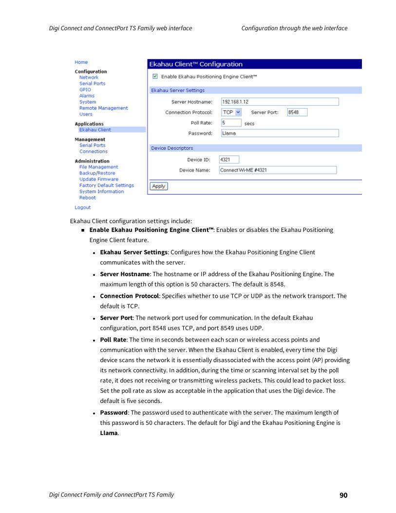
Digi Connect and ConnectPort TS Family web interface Configuration through the web interface
Digi Connect Family and ConnectPort TS Family 90
Ekahau Client configuration settings include:n Enable Ekahau Positioning Engine Client™: Enables or disables the Ekahau Positioning
Engine Client feature.
l Ekahau Server Settings: Configures how the Ekahau Positioning Engine Clientcommunicates with the server.
l Server Hostname: The hostname or IP address of the Ekahau Positioning Engine. Themaximum length of this option is 50 characters. The default is 8548.
l Connection Protocol: Specifies whether to use TCP or UDP as the network transport. Thedefault is TCP.
l Server Port: The network port used for communication. In the default Ekahauconfiguration, port 8548 uses TCP, and port 8549 uses UDP.
l Poll Rate: The time in seconds between each scan or wireless access points andcommunication with the server. When the Ekahau Client is enabled, every time the Digidevice scans the network it is essentially disassociated with the access point (AP) providingits network connectivity. In addition, during the time or scanning interval set by the pollrate, it does not receiving or transmitting wireless packets. This could lead to packet loss.Set the poll rate as slow as acceptable in the application that uses the Digi device. Thedefault is five seconds.
l Password: The password used to authenticate with the server. The maximum length ofthis password is 50 characters. The default for Digi and the Ekahau Positioning Engine isLlama.
Digi Connect and ConnectPort TS Family web interface Configuration through the web interface
Digi Connect Family and ConnectPort TS Family 91
n Device Descriptors:l Device ID: A numeric identifier for the Digi device, used internally by the Ekahau Positioning
Engine for device tracking over time. Each Digi device located on the network requires aunique identifier.
l Device Name: A descriptive name to identify the Digi device to users. The maximum lengthof this device name is 50 characters.
Industrial Automation-Modbus-BridgeIndustrial Automation is supported in these Digi devices: Digi Connect SP, Digi Connect Wi-SP, DigiConnect ME 4 MB, Digi Connect Wi-ME, Digi Connect EM, Digi Connect Wi-EM, and ConnectPort TS 8 and16.Currently, from the web interface, it is only possible to select a different port profile thanIndustrial Automation, or change the serial port settings, such as baud rate and parity. If changesare needed from the settings established by the Industrial Automation port profile, use the set iacommand from the command-line interface.For more information on Industrial Automation, see the set ia command description in the DigiConnect® Family Command Reference and the application note Remote Cellular TCP/IP Access to ModbusEthernet and Serial Devices available on the Digi Support site.
Known limitationsn You can use Digi RealPort only when the Modbus Bridge function is disabled. You cannot use
RealPort with Modbus/RTU or ASCII to access the Modbus Bridge function.
n The outgoing slave idle time used for remote Modbus IP-based slaves does not always closeidle sockets predictably.
n While the Modbus bridge is active, do not attempt to “Port Forward” TCP 502 or UDP 502 tolocal Modbus/TCP servers while the Modbus Bridge is active. This causes neither function towork. Disable the Modbus Bridge if you want traditional Router/NAT function for Modbus/TCPport 502.
Enable or disable Modbus BridgeTo enable or disable Modbus bridge, choose one of the following options:
n To disable the Modbus Bridge, select a different port profile than Industrial Automation.
n To enable Modbus Bride, reselect the Industrial Automation port profile.
Note Any specialized settings configured using the set ia commands are lost when you disablethe Modbus bridge. You must reconfigure these settings when you re-enable the IndustrialAutomation port profile.
Configuration through Digi Remote ManagerRemote Manager (formerly Device Cloud) is an on-demand service. After creating a Remote Manageraccount, you can connect to Remote Manager. There are no infrastructure requirements. Remotedevices and enterprise business applications connect to Remote Manager via standards-based WebServices.See the Remote Manager User Guide for details on:

Digi Connect and ConnectPort TS Family web interface Configuration through the web interface
Digi Connect Family and ConnectPort TS Family 92
n Using Remote Manager as a management interface
n Creating a Remote Manager account
n Adding your Digi Connect and ConnectPort TS Family device to the Remote Manager device listso you can manage it from that interface
IPv6 supportSelect Digi products support Internet Protocol version 6 (IPv6), electronic devices use this networklayer standard to exchange data across a packet-switched network. IPv6 is provides more addressesfor networked devices than IPv4.The primary change from IPv4 to IPv6 is the length of network addresses. IPv4 address are 32 bitslong. In contrast, IPv6 addresses are 128 bits long and are typically composed of two logical parts: a64-bit network prefix and a 64-bit host part, which is either automatically generated from theinterface’s MAC address or assigned sequentially.IPv6 addresses are normally written as eight groups of four hexadecimal digits. For example:3002:0ff2:63a5:0db8:42ae:0040:02de:3560. You can omit leading zeros in a group. If a four-digit groupis 0000, the zeros may be omitted, and that part of the address shortened to two consecutive colons,provided you use only one double colon in the address. You can write a sequence of four bytes at theend of an IPv6 address in decimal, using dots as separators.IPv6 networks are written using CIDR notation.An IPv6 network (or subnet) is a contiguous group of IPv6 addresses the size of which must be apower of two; the initial bits of addresses which are identical for all hosts in the network are calledthe network's prefix.A network is denoted by the first address in the network and the size in bits of the prefix, separatedwith a slash. For example, 2001:1234:5678:9ABC::/64 stands for the network with addresses2001:1234:5678:9ABC:: through 2001:1234:5678:9ABC:FFFF:FFFF:FFFF:FFFF.Because you can see a single host as a network with a 128-bit prefix, you will sometimes see hostaddresses written followed with /128.Implementation of IPv6 in Digi products means that there are more ways in which you can expressaddresses for devices and destinations:
n As an IPv4 address, for example 10.8.118.3.
n As an IPv6 address in any of its accepted notation formats, including address notation withspecial meanings, for example, 3002:0ff2:63a5:0db8:42ae:0040:02de:3560,
n As a Fully Qualified Domain Name (FQDN), for example www.myhost.com or remote3.digi.com.Use of an FQDN assumes there is a DNS server somewhere to resolve the name. For a DNSserver, it does not make sense to talk about a Fully Qualified Domain Name for it, since theserver itself is doing the resolving of names.
Digi’s implementation of IPv6 supports a dual stack. That is, each Digi device will have an IPv4 addressand potentially several IPv6 addresses:
n Link-local address: similar to AutoIP.
n Site-local address: router-assigned.
Important Digi’s IPv6 implementation does not allow assignment of static IPv6 addresses. A Digidevice gets either a link-local or site-local address.

Digi Connect and ConnectPort TS Family web interface Configuration through the web interface
Digi Connect Family and ConnectPort TS Family 93
Alternative configuration options for Digi Connect Wi-SPIf you configure the Digi Connect Wi-SP with a serial connection, there are several configurationoptions.
Configure the network using an access pointTo configure the network using an access point (infrastructure mode with SSID -Connect) for DigiConnect Wi-SP:
1. Configure the network using an access point with the SSID - Connect and all encryptiondisabled (such as WEP & WPA).
2. Power up the device.
3. Launch the Discovery program on your computer and proceed with the configuration.
Configure the wireless card without an access pointTo configure the wireless card without an access point (Ad-Hoc mode with SSID - Connect) for DigiConnect SP:
1. Configure the wireless card to operate in Ad-Hoc mode with the SSID - Connect.
2. Power up the device.
3. Launch the Discovery application on you computer and proceed with the configuration.
Set DIP switches on Digi Connect Wi-SP (or SP)To set the DIP switches on Digi Connect Wi-SP (or SP):
1. Disconnect the power supply.
Note ALWAYS disconnect the power supply before resetting the DIP switches.
2. Set the Digi Connect Wi-SP DIP switches in the On or up position. The following image showsthe DIP Switch settings required for command-line access for both the Digi Connect Wi-SP andthe Digi Connect SP.
3. Connect the Digi Connect Wi-SP to a computer with a serial cable.
4. Access a terminal emulation program such as HyperTerm. For example, select Start >Accessories > Communication > Hyperterm and type a name for the connection.

Digi Connect and ConnectPort TS Family web interface Configuration through the web interface
Digi Connect Family and ConnectPort TS Family 94
5. Select COM1 and click OK.
6. Set the port settings to 9600, 8, None, 1, None (default settings), click Apply and then click OK.
7. Type the default user name, root, and the default password, dbps.

Digi Connect and ConnectPort TS Family web interface Configuration through the web interface
Digi Connect Family and ConnectPort TS Family 95
8. Use the set wlan command to configure wireless network settings. This command is describedin the Digi Connect and ConnectPort TS Family Command Reference, available for download fromthe Digi Support site and, for products that ship with a Software and Documentation CD, on theCD.
9. After configuring the Digi Connect Wi-SP parameters to function within your network,disconnect the power supply and the serial cable from the Digi Connect Wi-SP.
10. Reset the DIP switch settings according to serial device requirements (EIA-232/422/485).
11. Connect the antenna and the power supply to the Digi Connect Wi-SP.
12. Start the Digi Device Setup Wizard to discover and configure the Digi Connect Wi-SP for yournetwork.
Note The Digi support website at www.digi.com/support provides additional command resources.
Batch configuration capabilitiesIf you need configure multiple Digi devices, use the batch configuration capabilities to uploadconfiguration files through the Digi Connect Programmer utility. The Digi Connect Programmer utilityis a command-line-based interface to Digi devices. Use this utility to upload firmware, files,configuration settings and factory defaults to a Digi device. You can run it from the command line on acomputer that uses the Microsoft Windows operating system.You can download the Digi Connect Programmer utility from the Digi website.The following table list some of the available commands.
Command Description
connectprog /help Displays the complete list of available commandoptions.
connectprog /discover Discovers devices on the local LAN. This isequivalent to using the Digi device Discoveryutility.
connectprog set /mac=<mac address> /ip=<ipaddress>
Sets the IP address for the device at theidentified MAC address.
connectprog /info /destip=<ip address>/username=root /password=dbps
Displays device information for the specificdevice.
connectprog /backup /destip=<ip address>/username=root /password=dbps
Backs up the complete device configuration toconfig.rci in the local directory.
connectprog /upload /destip=<ip address>/config=<directory path>\<file name>.txt/username=root /password=dbps
Uploads the configuration file to the device.
The following example displays the results for the discover command:connectprog /discover
Digi Connect ProgrammerVersion 1.6.25.0

Digi Connect and ConnectPort TS Family web interface Management
Digi Connect Family and ConnectPort TS Family 96
Copyright 2003-2009 Digi International Inc.
Searching for devices. Please wait...
IP Address | MAC Address | Model-----------------+-------------------+------------------------------
192.168.1.4 00:40:9D:12:34:56 ConnectPort TS 16-----------------+-------------------+------------------------------1 device found.
ManagementUse the Managementmenu to view andmanage connections and services for the Digi Connect andConnectPort TS Family product.You can monitor the port, device, system, and network activities of Digi Connect and ConnectPort TSFamily devices from a variety of interfaces. Changes in data flow may indicate problems or activitiesthat may require immediate attention.This chapter discusses monitoring and connection-management capabilities and tasks in Digi Connectand ConnectPort TS Family products.
Web interfaceThe web interface has several screens for monitoring Digi Connect and ConnectPort TS Familydevices:
n Network status
n Serial Port Management: for each port, the port’s description, current profile, port logs (ifactivated), and current serial configuration.
n Connections Management: A display of all active system connections.
n System Information:l General device information.
l Current GPIO pin states.
l Serial port information: for each port, including the port’s description, current profile,current serial configuration. The same information appears when you choose Serial PortManagement.
l Network statistics: statistics for IP, TCP, UDP, and ICMP.
Manage connections and servicesUse the Managementmenu to view andmanage connections and services for the Digi Connect andConnectPort TS Family product.
Serial Port ManagementThe Serial Port Management page (Management > Serial Ports) provides an overview of the serialports and their connections. Click Connections to display the active connections for a serial port. Youcan refresh the view to see new serial-port connections, and you can disconnect serial-portconnections as needed.

Digi Connect and ConnectPort TS Family web interface Administration
Digi Connect Family and ConnectPort TS Family 97
Port Connections ManagementThe Port Connections Management page (Management > Serial Ports > Connections) displays activesystem connections.
Manage active system connectionsThe Active System Connections list provides an overview of connections associated with variousinterfaces, such as:
n User connections to the device’s web interface
n Connections to the command line through the local shell
n Python threads currently running
n Protocols used for the connections
n The number of active sessions for each connection
Use this list to determine which connections are no longer needed. You can disconnect connectionsthat are no longer needed.
Event loggingManagement > Event Logging displays the event log for the Digi device. This log records eventsthroughout the Digi device’s system, such as starting or resetting the Digi device, configuring features,actions performed by various interfaces and subsystems, or starting applications. The event log isalways enabled and is not user-configurable. When the Digi device operates in an unexpectedmanner,you can send the log entries to Digi for analysis by Technical Support and Engineers. You cannotdisable the event log. Digi uses the event log to get an accurate view of all operational aspects of thedevice.The event log is maintained in RAM, and there is no history across reboots of the device. When the log“overflows” the oldest entries are overwritten with new ones, so the history is incomplete.The Clear button clears the event log.
Manage network servicesManagement > Network Services displays information about active network services. Currently, theonly network-service management task possible from this page is managing the DHCP server.
AdministrationYou can periodically perform administration tasks on Digi Connect and ConnectPort TS Familyproducts, such as:
n File management
n Changing the password used for logging onto the device
n Backing up and restoring device configurations
n Updating firmware and Boot/POST code
n Restoring the device configuration to factory defaults
n Rebooting the device
The Administration section in the web interface provides the following options:

Digi Connect and ConnectPort TS Family web interface Administration
Digi Connect Family and ConnectPort TS Family 98
n X.509 Certificate/Key Management: Load andmanage X.509 certificates and public/privatehost key pairs that are public key infrastructure (PKI) based security. See X.509 Certificate/KeyManagement for more information.
Note Only the ConnectPort TS 8/16 supports X.509 certificate/key Management.
n File Management: Upload andmanage files, such as custom web pages, applet files, andinitialization files. See File Management for more information.
n Python Program File Management: Upload custom programs in the Python programminglanguage to Digi devices and configuring the programs to execute automatically at startup. SeePython Configuration for more information.
n Backup/Restore: Back up or restore device configuration settings. See Backup/Restore formore information.
n Update Firmware: Update the firmware, including Boot and POST code. See Update thefirmware and boot/POST code for more information.
n Factory Default Settings: Restore a device to factory default settings. See Factory DefaultSettings for more information.
n System Information: Display general system information for the device and device statistics.See System Information for more information.
n Activate Find Me LED: On the Digi Connect ES model only, turn on/off the Find Me or locatorLED to aid in locating a specific Digi device. See Activate the Find Me LED for more information.
n Reboot: Reboot the device. See Reboot for more information.
These administrative tasks are organized elsewhere in the web interface:n Enable and disable network services. See Reboot for more information.
File ManagementUse the File Management page to upload custom files to a Digi Connect and ConnectPort TS Familyproduct, such as an image file containing your company logo. You can use custom applets and HTMLfiles to alter the interface either by adding a different company logo, changing colors, or movinginformation to different locations.If you upload an index.htm or index.html file, that file automatically loads when you sign in to a Digidevice from the web browser.
Upload filesTo upload files to a device:
1. Select Administration > File Management.
2. Click Choose File to locate and select the file.
3. Click Upload.
Delete filesTo delete files from a device:

Digi Connect and ConnectPort TS Family web interface Administration
Digi Connect Family and ConnectPort TS Family 99
1. Select Administration > File Management.
2. Select the Action check boxes next to files that you want to delete.
3. Click Delete.
Factory reset does not delete custom filesA factory reset does not delete files uploaded to the File Management page. When you restore the Digidevice to factory defaults or press the Reset button on the device (see Factory Default Settings), theuploaded files remain. This allows you to retain custom applets and custom factory defaults. If youwant to remove custom files you must manually delete them (see Delete files).
X.509 Certificate/Key ManagementUse the X.509 Certificate/Key Management page to upload andmanage entries in the database ofcertificate and private key data. This feature supports displaying, loading, saving, removing, certificatedatabase entries, and importing a private key for the Digi device into the database. Certificates andpublic/private host key pairs are an integral part of public key infrastructure (PKI) based security.
Supported security implementationsThe X.509 Certificate/Key Management manages several kinds of certificate databases and securityimplementations, including:
n X.509 Certificate Authority/Certificate Revocation—A trusted third party issues digitalcertificates for use by other parties.
n Secure Socket Layer (SSL)/Transport Layer Security (TLS)—Use SSL and TLS security tosecure access to web pages for configuration purposes, secure serial port connections, and SSLautoconnect, an automatic connection (autoconnection) between a serial port on the deviceand a remote network destination.
n Secure Shell (SSHv2)—Use SSHv2 to secure access to a device’s console and serial ports forconfiguration purposes.
Benefits of certificatesYou gain the following benefits when you use certificates to manage security:
n Certificates are more secure than Digi self-signed certificates.
n Certificate management allows you to push your own certificates out to Digi device.
n The key sizes are more flexible.
n When you manage certificates through the web interface, it creates a repository of certificatesthat other applications and processes can use.
Additional information on certificate managementImplementing certificate management requires selecting a security type and understanding itstechnical details and key operations. If you are tasked with certificate management for yourorganization and needmore background information, a good place to start is Wikipedia articles for thesecurity types (X.509 CA/CRL, SCEP, VPN, SSL/TLS), and SSH). These articles reference resources suchas standards, Request For Comments pages (RFCs), and articles that provide more technical detail.

Digi Connect and ConnectPort TS Family web interface Administration
Digi Connect Family and ConnectPort TS Family 100
Tables managed by the X.509 Certificate/Key Management featureCertificate and key management information is stored in the following database tables:
Security type Table Used to load
X.509 CertificateAuthority/CertificateRevocation
CA (CertificateAuthority)
Certificate authority digital certificates. Acertificate authority (CA) is a trusted third partythat issues digital certificates for use by otherparties. Digital certificates issued by the CAcontain a public key. The certificate containsinformation about the individual or organizationto which the public key belongs. A CA verifiesdigital certificate applicants' credentials. The CAcertificate allows verification of digitalcertificates, and the information containedtherein, issued by that CA.
CRL (CertificateRevocation List)
Certificate revocation lists for loaded CAs. Acertificate revocation list (CRL) is a file thatcontains the serial numbers of digital certificatesissued by a CA which have been revoked, andshould no longer be trusted. Like CAs, CRLs are avital part of a public key infrastructure (PKI). Youmust install the digital certificate of thecorresponding CA before you load the CRL.
Secure Sockets Layer (SSL)and Transport LayerSecurity (TLS)
SSL Identity SSL/TLS identity certificates. A default key isgenerated automatically but can be overriddenby a user. Note that this default key is notsecure.
SSL Identity Keys SSL/TLS identity private keys.
SSL Peer SSL/TLS peer certificates.
SSL Revoked Verbatim revoked SSL/TLS certificates.
Secure Shell (SSHv2) SSH Host KeysTable
SSHv2 identity private keys. Used forauthentication with SSHv2 clients and securekey exchange. A default 1024-bit DSA key isgenerated automatically if none exists when thedevice boots. There is no certificate for SSHv2,just private key data.
Behavior of SSH/SSL private keys on Digi deviceDigi devices generate their SSH/SSL self-signed private keys automatically. While this automaticgeneration is convenient for device users, as they are not required perform any actions regarding theprivate keys, it presents some security loopholes.
n With self-signed private keys, you must establish trust in a secure environment. That is, if youcannot guarantee that the environment is secure, you must pull the private keys off the Digidevice.

Digi Connect and ConnectPort TS Family web interface Administration
Digi Connect Family and ConnectPort TS Family 101
n You must know about the certificate before you connect, as opposed to third-party signedcertificates, where you only need the third-party certificate.
n The length of a Digi device’s self-signed private keys is 1024 bits. While this length is adequatefor 99.9% of all applications, some people or applications prefer a shorter or longer key.
Using TFTP to load and store certificate informationUse TFTP to load and store PEM-formatted certificates into the certificate and private keymanagement tables.
Using HTTP/HTTPS to transfer certificate and key dataYou can use HTTP or HTTPS to transfer certificate and private key data on a web browser.
Data retained after factory resetWhen you reset a Digi device to factory defaults, it retains certificates and private key data loadedonto it.
Certificate management settingsThere are separate pages of settings for the certificate databases and key management forcertificates and key data for the different types of security implementations.
Certificate Authorities (CAs) / Certificate Revocation Lists (CRLs)
Upload CAs and CRLsUse this section to upload andmanage certificate authority (CA) certificates, or certificate revocationlist (CRL) files. You can install up to 8 CA certificates and up to 8 CA revocations. You can also obtain CAcertificates from a SCEP server. You can install up to 8 SCEP CA certificates.You an use files in ASN.1 DER or PEM Base64 encoded formats. Click Choose File and type or browse tothe name of the file to upload. Click the Upload button to upload the file.
Installed Certificate Authority CertificatesThe table lists any certificate authority certificates that are loaded in the Certificate Authoritydatabase.
n Action: Select to perform allowable actions on the entry. The only allowable action is to deletethe entry.
n Subject: The entity that received the certificate. This is expressed as the value entered in abrowser’s URL field; typically a Fully Qualified Domain Name (FDQN) if using DNS or an IPaddress.
n Issuer: The entity that issued the certificate.
n Expiration: The expiration date of the certificate.
n Delete button: Click to delete the CA certificates selected in the Action column from thedatabase.
Digi Connect and ConnectPort TS Family web interface Administration
Digi Connect Family and ConnectPort TS Family 102
Installed Certificate Authority Certificate Revocation ListsThe table lists any certificate authority certificate revocation lists that are loaded in the CertificateRevocation List database.
n Action: Select to perform allowable actions on the entry. The only allowable action is to deletethe entry.
n Issuer: The entity that issued the certificate.
n Last Update: The last date and time the certificate revocation list was issued.
n Next Update: The effective or expiration date and time of the certificate revocation list. At thisdate, a new one must be obtained.
n Delete button: Click to delete the CA certificate revocation lists selected in the Action columnfrom the database.
Secure Socket Layer (SSL) / Transport Layer Security (TLS) CertificatesUse the Secure Sockets Layer (SSL) and Transport Layer Security (TLS) Certificates page to loadhost certificates and keys, as well as peer certificates and revocations.
Identity certificates and keysYou can install up to two SSL/TLS identity certificates. You can also install up to 2 SSL/TLS identitykeys.
Upload SSL/TLS Identity Keys and CertificatesUse this section to upload SSL/TLS RSA or DSA identity keys and certificates.You can use identity certificate and key files in ASN.1 DER or PEM Base64 encoded formats.Enter or browse to the name of the file to upload in the Upload File field. A password is required inthe Password field only if the host key file is encrypted. Click the Upload button to upload the file.
Installed SSL and TLS Identity CertificatesThis table lists the identity certificates that are installed in the SSL and TLS databases.
n Action: Select to perform allowable actions on the entry. The only allowable action is to deletethe entry.
n Subject: The entity that received the certificate.
n Issuer: The entity that issued the certificate.
n Expiration: The expiration date of the certificate.
n Matching Key: The private key associated with the certificate, if any exists.
n Delete button: Deletes all certificates selected in the Action column from the database.
Installed SSL/TLS identity keysThis table lists the identity keys that are installed in the SSL and TLS databases.
n Action: Select to perform allowable actions on the entry. The only allowable action is to deletethe entry.
n Type: The type of encryption of the identity key: RSA (public key cryptography algorithm) orDSA (digital signature algorithm).
Digi Connect and ConnectPort TS Family web interface Administration
Digi Connect Family and ConnectPort TS Family 103
n Matching Certificate: The certificate associated with the private key, if any exists.
n Delete button: Deletes all keys selected in the Action column from the database.
Trusted peer certificateUse this section to upload andmanage SSL and TLS trusted peer certificates.
Upload SSL/TLS trusted peer certificatesUse this section to upload SSL/TLS trusted peer certificates. Certificate files can be in ASN.1 DER orPEM Base64 encoded formats. Enter or browse to the name of the file to upload in the Upload Filefield. Click the Upload button to upload the file.
Installed SSL/TLS trusted peer certificatesThis table lists the installed SSL and TLS trusted peer certificates. You can install up to 8 SSL/TLStrusted peer certificates.
n Action: Select to perform allowable actions on the entry. The only allowable action is to deletethe entry.
n Subject: The entity that received the certificate.
n Issuer: The entity that issued the certificate.
n Expiration: The expiration date of the certificate.
n Delete button: Deletes all certificates selected in the Action column from the database.
Untrusted revoked certificateUse this section to upload andmanage SSL/TLS untrusted revoked certificates. You can install up to 8SSL/TLS untrusted revoked certificates.
Upload SSL/TLS untrusted revoked certificatesUse this section to upload SSL/TLS untrusted revoked certificates. Certificate files can be in ASN.1 DERor PEM Base64 encoded formats. Enter or browse to the name of the file to upload in the Upload Filefield. Click the Upload button to upload the file.
Installed SSL/TLS untrusted revoked certificatesThe table lists the installed SSL and TLS untrusted revoked certificates.
n Action: Select to perform allowable actions on the entry. The only allowable action is to deletethe entry.
n Subject: The entity that received the certificate.
n Issuer: The entity that issued the certificate.
n Expiration: The expiration date of the certificate.
n Delete button: Deletes all certificates selected in the Action column from the database.
Secure Shell (SSH) Host KeysUse the Secure Shell (SSH) Host Keys page to upload andmanage SSH host keys.

Digi Connect and ConnectPort TS Family web interface Administration
Digi Connect Family and ConnectPort TS Family 104
Upload SSH Host KeysUse this section to upload SSH RSA or DSA hostkeys. Key files can be in ASN.1 DER or PEM Base64encoded formats. Enter or browse to the name of the file to upload in the Upload File field. Apassword is required in the Password field only if the host key file is encrypted. Click the Uploadbutton to upload the file.
Installed SSH host keysThe table lists the installed SSH host keys. You can install up to 2 SSH host keys.
n Action: Select to perform allowable actions on the entry. The only allowable action is to deletethe entry.
n Type: The type of encryption of the identity key: RSA (public key cryptography algorithm) orDSA (digital signature algorithm).
n Fingerprint: The fingerprint of the SSH host key. This fingerprint is in the form of a hash codeconsisting of several hexadecimal bytes to identify the SSH host key.
n Delete button: Deletes the selected SSH host keys in the Action column from the database.
Secure Shell (SSH) hostkeysUse the Secure Shell (SSHv2) Hostkeys database to load host private keys. You can use SSHv2 hostkeys for authentication with SSHv2 clients and secure key exchange. The Digi device automaticallygenerates a default 1024-bit DSA key if none exists when the Digi device boots.
n Upload SSH Host Keys: Use this section to upload SSH RSA or DSA hostkeys. Key files may bein ASN.1 DER or PEM Base64 encoded formats. If the host key file is encrypted, a password isrequired.
n Installed SSH Host Keys: Lists the host keys loaded into the SSH Hostkeys database.
Backup/RestoreAfter you configure a Digi Connect and ConnectPort TS Family device, back up the configurationsettings. You can restore the backup configuration settings if a problem occurs when updating thefirmware or adding hardware. If you need to configure multiple devices, you can use thebackup/restore feature to load the backup configuration settings from the first device onto the otherdevices.
Back up or restore a device configuration from the web interfaceYou can back up or restore a device configuration to a server from the web-interface and download aconfiguration from a server to a file or TFTP.
Note If you are using TFTP, ensure that the TFTP program is running on a server.
To backup a device configuration:1. Click Administration > Backup/Restore. The Backup/Restore page appears.
2. Select the storage location type.
3. Click Backup.To restore a device configuration:
Digi Connect and ConnectPort TS Family web interface Administration
Digi Connect Family and ConnectPort TS Family 105
1. Click Administration > Backup/Restore. The Backup/Restore page appears.
2. Select the storage location type.
3. Select the file to restore from the Restore From File field or click Choose File to locate andselect the file.
4. Click Restore.
Update the firmware and boot/POST codeYou can update the firmware and/or boot/POST code for a Digi device from a file on a computer orthrough TFTP. The recommendedmethod is to download the firmware to a local hard drive. TFTP issupported for those using Unix systems. Both the firmware and the boot/POST code are updatedusing the same set of steps. The Digi device automatically determines the type of image to upload.
Important Read the Release Notes supplied with the firmware to see if the boot/POST code must beupdated before updating the firmware or the boot/POST code.
Update the firmware from a file on a computerTo update the firmware from a file on a computer:
1. Select Administration > Update Firmware. The Update Firmware page appears.
2. Type the name of the firmware or POST file in the Select Firmware field, or click Browse tolocate and select the firmware or POST file.
3. Click Update.
Important: DO NOT close the browser until the update completes and a reboot promptappears.
Update the firmware from a TFTP ServerYou can update firmware from a TFTP server through the command-line interface using the bootcommand. You cannot update the firmware from the web interface. For details, see Administration.
Factory Default SettingsRestoring a Digi Connect and ConnectPort TS Family device to its factory default settings clears allcurrent configuration settings, except the IP address settings and administrator password with someexceptions. See the following topics for more information:
n Settings cleared and retained during a factory reset
n File Management
There are several ways to reset the device configuration of a Digi Connect and ConnectPort TS Familyproduct to the factory default settings:
n From the web interface using the Restore Factory Defaults operation
This method is the best way to reset the configuration, because you can back up the settingsusing the Backup/Restore operation. The Backup/Restore operation provides a means torestore the configuration after the configuration issues have been resolved. See Reset the

Digi Connect and ConnectPort TS Family web interface Administration
Digi Connect Family and ConnectPort TS Family 106
factory settings on a Digi Connect and ConnectPort TS Family product from the web interfacefor more information.
n From the command-line interface, using the boot command
n Using the reset button on the Digi Connect and ConnectPort TS Family device
Use this method if you cannot access the device from a web browser. The location of the resetbutton may vary. See Reset the factory settings on a Digi Connect and ConnectPort TS Familyproduct using the Reset button for more information.
Settings cleared and retained during a factory resetA factory reset does not delete files uploaded to the File Management page. See Factory reset doesnot delete custom files for more information.If a Digi device has custom default settings, the settings revert to those custom defaults instead ofthe factory defaults.Restoring the Digi device to its factory default settings clears all current settings except the IPaddress settings and the administrator password. All custom-interface files and applet files that youuploaded from the File Management page are retained. See File Management for information onuploading and deleting files.
Reset the factory settings on a Digi Connect and ConnectPort TS Family productfrom the web interfaceTo reset the factory settings on the Digi Connect and ConnectPort TS Family device from the webinterface:1. Create a backup copy of the configuration using the Backup/Restore operation. See
Backup/Restore for more information.
2. Select Administration > Factory Default Settings. The Factory Default Settings page appears.
3. To keep the network settings for the device, such as the IP address, select the Keep networksettings check box.
4. Click Restore.
Reset the factory settings on a Digi Connect and ConnectPort TS Family productusing the Reset buttonTo reset the factory settings on a Digi Connect and ConnectPort TS Family product using the Resetbutton:

Digi Connect and ConnectPort TS Family web interface Administration
Digi Connect Family and ConnectPort TS Family 107
1. Power off the Digi Connect and ConnectPort TS Family.
2. Locate the Reset button or pin on your Digi device. Here is the reset button for a Digi ConnectSP unit.
For Digi Connect EM or Digi Connect Wi-EM, the Reset button is located between P3 and CR1,as shown:
Digi Connect ME and Digi Connect Wi-ME do not have a reset button. Instead, pin 20 (the /init pin) isshorted to ground.For Digi Connect ES, the reset switch is on the side panel.
3. Hold the Reset button down gently with a non-conductive, small diameter tool (such as woodor plastic) with a blunt end (NOT SHARP or the button could be damaged). Power on the devicewhile holding the Reset button down. On some models, after a few seconds you may see theStatus LED blink a 1-1-1 pattern once.
For Digi Connect ME and Digi Connect Wi-ME, short pin 20 (the /init pin) to ground during bootup to restore the module to factory defaults. Note that shorting pin 14 simply reboots the unitbut does not restore the configuration.

Digi Connect and ConnectPort TS Family web interface Administration
Digi Connect Family and ConnectPort TS Family 108
4. After 30 seconds, release the Reset button. At this point, on some models, the Status LED willblink a 1-5-1 pattern. Wait for the device to boot up. At this time, the configuration is returnedto factory defaults. Now, if desired, power off the device, though this is not necessary.
Note Powering off the device before releasing the Reset button guarantees the configurationwill NOT be reverted. Powering off the device just after releasing the Reset button will result inan unknown configuration, possibly causing some or all settings to revert to defaults.

Digi Connect and ConnectPort TS Family web interface Administration
Digi Connect Family and ConnectPort TS Family 109
System InformationThe System Information page displays general system information about the Digi Connect andConnectPort TS Family device. Technical support uses this information to troubleshoot problems. Todisplay these pages, go to Administration > System Information.
GeneralThe General page displays the following general system information:
n Model: The model of the Digi Connect and ConnectPort TS Family product.
n MAC Address: A unique network identifier required for all network devices. The MAC addressappears on a sticker on the Digi device and consists of 12 hexadecimal digits, usually startingwith 00:40:9D.
n Firmware Version: The current firmware version running in the Digi device. Use thisinformation to locate and download new firmware. You can download firmware updates fromthe Digi Support site.
n Boot Version: The current boot code version running in the Digi device.
n POST Version: The current Power-On Self Test (POST) code version running in the Digi device.
n CPU Utilization: The amount of CPU resources the Digi device uses.
Important: 100% CPU utilization may indicate encryption key generation is in-progress. Oninitial boot, the Digi device generates some encryption key material: an RSA key for SSL/TLSoperations, and a DSA key for SSH operations. This key-generation process can take as long as40 minutes. Until the RSA or DSA key is generated, the Digi device will be unable to initiate oraccept that type of encrypted connection. The Digi device reports itself as 100% busy, but sincekey generation occurs at a low priority, the device will still function normally. On subsequentreboots, the Digi device will use its existing keys and not need to generate another unless areset to factory defaults is done, which will cause a new key to be generated on the nextreboot.
n Up Time: The amount of time the Digi device has been running since it was last powered on orrebooted.
n Total/Used/Free Memory: The amount of memory (RAM) available, currently in use, andcurrently not being used.
n Power status: For models with dual power supply, Power status shows the status of thepower supplies. For example, if power supply 1 for a Digi Connect and ConnectPort TS Family 16MEI unit is disconnected but power supply 2 is connected, the power status appears as follows:
Power status: Dual power (1 - Fail, 2 - Normal)
SerialThe Serial page under Administration > System Information lists the configured serial ports for theDigi Connect and ConnectPort TS Family products. Click a port to view detailed serial port information
Digi Connect and ConnectPort TS Family web interface Administration
Digi Connect Family and ConnectPort TS Family 110
on the Serial Port Diagnostics page.
Serial Port DiagnosticsThe Serial Port Diagnostics page displays information on the current state of a serial port on your Digidevice.
n Configuration: The Configuration page displays the electrical interface (Port Type) and basicserial settings.
n Signals: The Signals pane shows the state of serial port signals. The serial port signals aregreen when asserted (on) and gray when not asserted (off). These signals are defined asfollows:l RTS: Request To Send.
l CTS: Clear To Send.
l DTR: Data Terminal Ready.
l DSR: Data Set Ready.
l DCD: Data Carrier Detected.
l OFC: Output Flow Control. Indicates that flow control is enabled on the remote side of theserial-port connection, and that the Digi device should stop sending data.
l IFC: Input Flow Control. Indicates that the Digi device is operating as if flow control isenabled for incoming data sent from the remote side of the serial-port connection. Thissignal is more of an indication that flow control is intended or expected rather than truestate information. If the remote side has a flow-control mechanism enabled, the Digi devicewill use it.
n Serial Statistics: The Statistics section includes data counters and error tracking that will helpdetermine the quality of data that is being sent or received. If the error counters areaccumulating, you may have a problem with your Digi device server.
l Total Data In: Total number of data bytes received.
l Total Data Out: Total number of data bytes transmitted.
l Overrun Errors: Number of overrun errors—the next data character arrived before thehardware could move the previous character.
l Framing Errors: Number of framing errors received—the received data did not have a validstop bit.
l Parity Errors: Number of parity errors—the received data did not have the correct paritysetting.
l Breaks: Number of break signals received.
GPIOThe GPIO pane displays the current state of the General Purpose I/O pins on the Digi device. You canchange the state of pins configured for output, as discussed in GPIO pins. Alarms can be issued whenGPIO pins change state, as discussed in Alarms Configuration.

Digi Connect and ConnectPort TS Family web interface Administration
Digi Connect Family and ConnectPort TS Family 111
Network statisticsNetwork pane provide details about network and protocol activity that may aid in troubleshootingnetwork communication problems. Statistics displayed are those gathered since the unit was lastrebooted. If an error counter accumulates at an unexpected rate for that type of counter, there maybe a problem in the Digi Connect and ConnectPort TS Family product.
Ethernet Connection Statisticsn Speed: Ethernet link speed: 10 or 100 Mbps. N/A if link integrity is not detected. For example,
the cable is disconnected.
n Duplex: Ethernet link mode: half or full duplex. N/A if link integrity is not detected. For example,the cable is disconnected.
n Bytes Received/Bytes Sent: Number of bytes received or sent.
n Unicast Packets Received: Number of unicast packets received and delivered to a higher-layer protocol. A unicast packet is directed to an Ethernet MAC address.
n Non-Unicast Packets Received: Number of non-unicast packets received and delivered to ahigher-layer protocol. A non-unicast packet is directed to either an Ethernet broadcast addressor a multicast address.
n Non-Unicast Packets Sent: Number of non-unicast packets requested to be sent by a higher-layer protocol. A non-unicast packet is directed to either an Ethernet broadcast address or amulticast address.
n Unknown Protocol Packets Received: Number of received packets discarded because of anunknown or unsupported protocol.
IP statisticsn Datagrams Received/Datagrams Forwarded: Number of received or forwarded datagrams.
n Forwarding: Displays whether forwarding is enabled or disabled.
n No Routes: Number of outgoing datagrams for which no route to the destination IP can befound.
n Routing Discards: Number of discarded outgoing datagrams.
n Default Time-To-Live: Number of routers an IP packet can pass through before it is discarded.
TCP Statisticsn Segments Received/Segments Sent: Number of received or sent segments.
n Active Opens: Number of active opens. In an active open, the Digi Connect and ConnectPort TSFamily product initiates a connection request with a server.
n Passive Opens: Number of passive opens. In a passive open, the Digi Connect and ConnectPortTS Family listens for a connection request from a client.
n Bad Segments Received: Number of segments received with errors.
n Attempt Fails: Number of failed connection attempts.

Digi Connect and ConnectPort TS Family web interface Administration
Digi Connect Family and ConnectPort TS Family 112
n Segments Retransmitted: Number of retransmitted segments. Segments are retransmittedwhen the server does not respond to a packet sent by the client. A retransmit limits thenumber of lost and discarded packets.
n Established Resets: Number of established connections that have been reset.
UDP Statisticsn Datagrams Received/Datagrams Sent: Number of datagrams received or sent.
n Bad Datagrams Received: Number of bad datagrams received. This number does not includethe value contained by No Ports.
n No Ports: Number of received datagrams that were discarded because the specified port wasinvalid.
ICMP Statisticsn Messages Received: Number of messages received.
n Bad Messages Received: Number of receivedmessages with errors.
n Destination Unreachable Messages Received: Number of destination unreachable messagesreceived. A destination unreachable message is sent to the originator when a datagram fails toreach its intended destination.
Wi-Fi LAN Statistics
n Status: The current status of the wireless Digi device, which may include:l Not Connected: not associated or connected w/ any access point, perhaps because the
wireless device has not fully initialized, is out of range, or the wireless interface isdisconnected because the Ethernet interface is enabled.
l Searching for Network: searching for a wireless network or access point for connection.
l Associated with Network: successfully associated with the network w/ the propernetwork settings and encryption.
l Authenticated with Network: successfully authenticated a user name and password withthe network when WPA is enabled.
l Joined Ad Hoc Network: successfully connected to and joined an ad-hoc network.
l Started Ad Hoc Network: successfully created, started, and joined an ad-hoc network.
n Network Name: The name of the wireless network to which the Digi device is connected.
n Network ID: The ID of the wireless network to which the Digi device is connected andcommunicating.
n Channel: The frequency channel that the wireless LAN radio uses for the Digi device.
n Transmit Rate: The current transmission rate for the wireless LAN radio.
n Signal Strength: The current receive signal strength as reported by the wireless LAN radio.Ranges are from 0 to 100.

Digi Connect and ConnectPort TS Family web interface Administration
Digi Connect Family and ConnectPort TS Family 113
Remote Manager statusUse the Remote Manager status section to view the connection status for the Remote Managerservice.
DiagnosticsUse the ping utility on the Diagnostics page to determine whether the Digi device can access remotedevices over the network. Type the host name of the remote device you want to access, and clickPing.
Activate the Find Me LEDFor Digi Connect ES products, use the Find Me LED to aid in finding a specific Digi device server amonga group of devices. The locator LED is shown on Digi Connect 48 SB and Digi Connect 4/8 SB withswitch.
n Activate: Click this button to activate the Find Me locator LED. The Find Me locator LED startsblinking.
n Stop: Click this button to deactivate the Find Me locator LED. The Find Me locator LED stopsblinking.
RebootChanges to some device settings require saving the changes and rebooting the Digi Connect andConnectPort TS Family. Use the Reboot page to reboot the Digi Connect and ConnectPort TS Family.To reboot a Digi Connect and ConnectPort TS Family from the web interface:
1. Select Administration > Reboot.
2. Click the Reboot button. Wait approximately one minute for the reboot to complete.
Enable/disable access to network servicesYou can enable and disable access to various network services, such as ADDP, RealPort, SNMP, andtelnet. For example, you can disable access to all network services that are not required for running orinterfacing with the Digi Connect and ConnectPort TS Family product for performance and securityreasons. From the web interface, you can enable and disable network services on the NetworkServices Settings page for a Digi Connect and ConnectPort TS Family product. See Network ServicesSettings.

Digi Connect and ConnectPort TS Family command-line interface
You can issue commands from the command line to configure, manage, andmonitor Digi Connect andConnectPort TS Family devices. For a description of the complete command set, see the Digi Connect®Family Command Reference.This section gives some basics for using the command line interface, as well as listing some commonlyused commands by function.
Configuration through the command line 115Management through the command line interface 116Administration 122
Digi Connect Family and ConnectPort TS Family 114

Digi Connect and ConnectPort TS Family command-line interface Configuration through the command line
Digi Connect Family and ConnectPort TS Family 115
Configuration through the command lineYou can configure the Digi Connect and ConnectPort TS Family product by entering a series ofcommand to set values through the command-line interface.
Access the command-line interfaceTo access the command-line interface and send configuration commands to the Digi Connect andConnectPort TS Family device:
1. Launch the command-line interface by using the telnet command.
2. To launch the CLI via telnet, issue the following telnet command from a command prompt onanother networked device, such as a server:
#> telnet ip-address
Replace ip-addresswith the IP address of the Digi Connect and ConnectPort TS Family device.For example:
#> telnet 192.3.23.5
If security is enabled for the Digi Connect and ConnectPort TS Family device, a login promptappears for telnet access. If you do not know the user name and password for the device,contact the system administrator who originally configured the device.
Basics for using the command-line interfaceThe Digi Connect and ConnectPort TS Family offers online help for CLI commands. Use the followingcommand examples to get help for using commands.
n help displays all supported commands for a device.
n ? displays all supported commands for a device.
n set ? displays the syntax and options for the set command. Use this command to determinewhether the device includes a particular set command variant to configure various features.
n help set displays syntax and options for the set command.
n set serial ? displays the syntax and options for the set serial command.
n help set serial displays the syntax and options for the set serial command.
Basics for using the command-line interfaceThe Digi Connect and ConnectPort TS Family offers online help for CLI commands. Use the followingcommand examples to get help for using commands.
n help displays all supported commands for a device.
n ? displays all supported commands for a device.
n set ? displays the syntax and options for the set command. Use this command to determinewhether the device includes a particular set command variant to configure various features.
n help set displays syntax and options for the set command.
Digi Connect and ConnectPort TS Family command-lineinterface
Management through the command lineinterface
Digi Connect Family and ConnectPort TS Family 116
n set serial ? displays the syntax and options for the set serial command.
n help set serial displays the syntax and options for the set serial command.
Management through the command line interfaceThis section provides information on some key commands available from the command line interface.For more information, see the Digi Connect Family Command Reference on www.digi.com.Use the following commands to display information and statistics:
n display
n info
n set alarm
n set buffer and display buffer
n set gpio
n set snmp
n show
Use the following commands to manage connections and sessions:n close
n connect
n exit and quit
n reconnect
n rlogin
n send
n status
n telnet
n who and kill
Use the following commands to configure the product:n backup print
n newpass
n sendmode
n set alarm
n set autoconnect
n set buffer and display buffer
n set forward
n set gpio
n set group
n set host
n set mgmtconnection
n set mgmtglobal

Digi Connect and ConnectPort TS Family command-lineinterface
Management through the command lineinterface
Digi Connect Family and ConnectPort TS Family 117
n set mgmtnetwork
n set network
n set permissions
n set pmodem
n set pppoutbound
n set profiles
n set realport
n set rtstoggle
n set serial
n set service
n set snmp
n set system
n set tcpserial
n set udpserial
n set user
n set wlan
closeUse the close command to close active sessions that were opened by connect, rlogin, and telnetcommands.
connectUse the connect command to establish a connection with a serial port.
displayUse the display commands to display real-time information about a device, such as:
n General product information, including the product name, MAC address, boot, post, andfirmware versions, memory usage, utilization, and uptime, or the amount of time since thedevice was booted (display device).
n Active interfaces on the system. These include the web interface, command line interface,Point-to-Point Protocol (PPP), and Ethernet interface, and their status, such as Closed orConnected (display netdevice).
n GPIO signals (display gpio).
n Logged serial data (display logging/).
n Memory usage information (display memory).
n Serial modem signals (display serial).
n General status of the sockets resource (display sockets).

Digi Connect and ConnectPort TS Family command-lineinterface
Management through the command lineinterface
Digi Connect Family and ConnectPort TS Family 118
n Active TCP sessions and active TCP listeners (display tcp).
n Current UDP listeners (display udp).
n Uptime information (display uptime).
exit and quitUse the exit and quit commands to terminate a currently active session.
infoUse the info commands to display statistical information about a device over time. The statisticsdisplayed are those gathered since the tables containing the statistics were last cleared. The type ofstatistics include:
n Device statistics. The info device command displays such details as product, MAC address,boot, POST, and firmware versions, memory usage, utilization, and uptime.
n Ethernet statistics. The info ethernet command displays statistics regarding the Ethernetinterface, including:l The number of bytes and packets sent and received
l The number of incoming and outgoing bytes that were discarded or that contained errors
l The number of Rx overruns
l The number of times the transmitter was reset
l The number of incoming bytes when the protocol was unknown
n ICMP statistics. The info icmp command displays the number of messages, badmessages, anddestination unreachable messages received.
n Serial statistics. The info serial command displays the following information:l Number of bytes received and transmitted
l Signal changes
l FIFO and buffer overruns
l Framing and parity errors
l Breaks detected
n TCP statistics. The info tcp command displays the following information:l The number of segments received or sent
l The number of active and passive opens
l The number of bad segments received
l The number of failed connection attempts
l The number of segments retransmitted
l The number of established connections that were reset

Digi Connect and ConnectPort TS Family command-lineinterface
Management through the command lineinterface
Digi Connect Family and ConnectPort TS Family 119
n UDP statistics. The info udp command displays the following information:l The number of datagrams received or sent
l The number of bad datagrams received
l The number of received datagrams that were discarded because the specified port wasinvalid
n Wireless statistics. The info wlan command displays detailed statistics for wireless devicesthat may aid in troubleshooting network communication problems with a wireless network.
newpassUse the newpass command to issue a new password to a user.
pingUse the ping command to test whether a host or other device is active and reachable.
reconnectUse the reconnect command to reestablish a connection opened by a connect, rlogin, or telnetcommand. By default, the reconnect command reestablishes the connection to the last activesession.
rloginUse the rlogin command to sign in to a remote system.
sendUse the send command to send a telnet control command, such as break, abort output, are you there,escape, or interrupt process, to the last active telnet session.
send modeUse the send mode command to configure the telnet control commands. For example, send telnetcontrol command to last active telnet session or set telnet operating options.
set alarmUse the set alarm command to display alarm settings, including conditions that trigger alarms, andhow alarms are sent. You can configure alarms to be sent as either an email message, an SNMP trap,or both. You can configure the alarms as needed.
set autoconnectUse the set autoconnect command to configure the autoconnection behaviors for serial portconnections.

Digi Connect and ConnectPort TS Family command-lineinterface
Management through the command lineinterface
Digi Connect Family and ConnectPort TS Family 120
set buffer and display buffersUse the set buffer command to configure buffering parameters on a port and display the current portbuffer configuration. The display buffers command displays the contents of a port buffer, ortransfers the port-buffer contents to a server running Trivial File Transfer Protocol (TFTP).
set forwardUse the set forward command to configure IP forwarding.
set gpioUse the set gpio to display current GPIO pin settings. You can reconfigure the pin settings as needed.
set groupUse the set group command to configure create, establish, update, or remove group attributes.
set hostUse the set host command to configure the host name for the Digi device.
set mgmtconnectionUse the set mgmtnetwork command to configure the Remote Manager connection settings.
set mgmtglobalUse the set mgmtglobal command to configure the Remote Manager global settings.
set mgmtnetworkUse the set mgmtnetwork command to configure the Remote Manager network settings.
set networkUse the set network command to configure the network options.
set permissionsUse the set permissions command to configure the user permissions for various services andcommand-line interface commands.
set pmodemUse the set pmodem command to configure the modem emulation.
set pppoutboundUse the set pppoutbound command to configure the PPP outbound connections.

Digi Connect and ConnectPort TS Family command-lineinterface
Management through the command lineinterface
Digi Connect Family and ConnectPort TS Family 121
set pppUse the set ppp command to configure PPP connections.
set profilesUse the set profiles command to configure the port profile for a serial port.
set realportUse the set realport command to configure RealPort.
set rtstoggleUse the set rtstoggle command to configure the RTS toggle.
set serialUse the set serial command to configure the serial port options.
set serviceUse the set service command to configure the network services.
set snmpUse the set snmp command to configure SNMP, including SNMP traps, such as:
n Authentication failure
n Cold start
n Link up
n Login traps
The set snmp command also displays current SNMP settings.
set systemUse the set system command to configure the system identifying information.
set tcpserialUse the set tcpserial command to configure serial TCP.
set usbUse the set usb command to configure the USB.
set udpserialUse the set udpserial command to configure the serial UDP.

Digi Connect and ConnectPort TS Family command-line interface Administration
Digi Connect Family and ConnectPort TS Family 122
set userUse the set user command to configure a user.
set wlanUse the set wlan command to configure wireless devices.
set wlanUse the set wlan command to configure wireless devices.
statusUse the status command to display a list of sessions or outgoing connections made by the connect,rlogin, or telnet commands for a Digi device. Use the status command to determine which of thecurrent sessions to close.
showUse the show commands to display current settings on a Digi device.
telnetUse the telnet command to establish an outgoing telnet connection, also known as a session.
who and killUse the who command to display a global list of connections. The list of connections includes thoseassociated with a serial port or the command-line interface.Use the kill command to terminate active connections based on the ID number returned from thewho results.Use the who command to determine any connections that are no longer needed, and end theconnections by issuing a kill command.
AdministrationYou can issue commands from the command-line interface to administer Digi Connect andConnectPort TS Family products. The following table displays several administration tasks and thecommands used to perform them. See the Digi Connect® Family Command Reference for morecomplete command descriptions.
Administrative task Command
Backup/restore a configuration from aTFTP server on the network
backup

Digi Connect and ConnectPort TS Family command-line interface Administration
Digi Connect Family and ConnectPort TS Family 123
Administrative task Command
Update firmware bootTo update the firmware:
1. Telnet to the Digi device command-line interfaceusing a telnet application or hyperterm.
2. If security is enabled for the Digi device, a loginprompt appears. The default user name is root andthe default password is dbps. If these defaults donot work, contact the system administrator whoset up the device.
3. If you are at the bash shell, type configshell to getto the config shell.
4. Issue the boot load command:
#> boot load=tftp-server-ip:filename
Replace tftp-server-ipwith the IP address of theTFTP server that contains the firmware, andreplace filenamewith the name of the file to upload.
Reset configuration to factory defaults revertorboot action=factory
Display system information andstatistics
info
Reboot the device boot
Enable/disable network services set service

Remote Manager monitoring capabilities
You can monitor andmanage Digi Connect and ConnectPort TS Family products from RemoteManager. For example, you can:
n Display detailed state information and statistics about a device, such as device up time,amount of used and free memory, network settings, XBee network overview and detailedinformation on network nodes.
n Manage mobile settings.
n Monitor the state of the device’s connection and see a connection report and connectionhistory statistics.
n Redirect devices to a to a different destination.
n Disconnect devices.
n Remove devices from the network.
To learn more about Remote Manager and the services it provides, see the Digi RemoteManager User Guide.
Remote Manager device management 125
Digi Connect Family and ConnectPort TS Family 124

Remote Manager monitoring capabilities Remote Manager device management
Digi Connect Family and ConnectPort TS Family 125
Remote Manager device managementFrom the Remote Manager’s device management view, you can sort monitoring capabilities by theserver and the devices managed by the server. The information is available in logs and generatedreports. When available, the reports post linked totals that you can use to drilled back to the originaldevices.
SNMP device monitoring capabilities
SNMP provides the following device monitoring capabilities:n Network statistics, defined in RFC 1213, MIB-II
n Port statistics, defined in RFCs 1316 and 1317
n Device information, defined in Digi enterprise MIB DIGI-DEVICE-INFO.mib
You can use this information to manage network performance, gather device statistics, and find andsolve network problems.For more information on the statistics available through the standard RFCs listed above, refer to theRFCs available on the IETF website (www.ietf.org). For enterprise MIBs, refer to the description fieldsin the MIB text.
Supported RFCs and MIBsDigi Connect and ConnectPort TS Family supports the following SNMP-related Request for Comments(RFCs) and Management Information Bases (MIBs):
n Standard RFCs and MIBsl RFC 1213—Management Information Base (MIB) II manages a TCP/IP network. MIB-II
contains variable definitions that describe the most basic information needed to manage aTCP/IP network. Variable definitions are organized into several groups, such as groups formanaging the system, network interfaces, address translation, transmission media, andvarious protocols, including IP, ICMP, TCP, UDP, EGP, and SNMP. Seewww.ietf.org/rfc/rfc1213.txt for more information.
l RFC 1215—Generic Traps (coldStart, linkUp, authenticationFailure, login only). Seewww.ietf.org/rfc/rfc1215.txt for more information.
l RFC 2790—Host Resources MIB for use with managing host systems, where “host” meansany computer that communicates with other similar computers attached to the Internet.See tools.ietf.org/html/rfc2790 for more information.
Digi Connect Family and ConnectPort TS Family 126
SNMP device monitoring capabilities SNMP configuration
Digi Connect Family and ConnectPort TS Family 127
n DIGI enterprise MIBsl DIGI CONNECT DEVICE INFO MIB—A Digi enterprise MIB for handling and displaying basic
device information, such as firmware revisions in use, device name, IP networkinformation, memory use, and CPU statistics.
l Digi Connect Mobile Information MIB—A Digi enterprise MIB for handling and displayingdevice information for mobile devices.
l Digi Connect Wireless LAN MIB—A Digi enterprise MIB for handling and displaying basicdevice information for wireless devices.
l DIGI SERIAL ALARM TRAPS MIB—A Digi enterprise MIB for sending alarms as SNMP traps.
l Digi Login Traps MIB—A Digi enterprise MIB that indicates when users attempt to sign intothe device, and whether the attempt was successful.
l Digi Structures of Management MIB—A Digi enterprise MIB that provides data structuresfor managing hosts and gateways on a network.
l Digi Connect Mobile Traps MIB—A Digi enterprise MIB for sending alarms as SNMP traps formobile devices.
l Digi Connectware Notifications MIB—This Digi enterprise MIB may be required by someSNMP import facilities, as other MIBs may refer to it.
See Download a Digi MIB for instructions on downloading a Digi MIB from the Digi website.
SNMP configurationYou can configure basic network and serial configurations for Digi Connect and ConnectPort TS Familydevices through SNMP:
n Use a subset of standard MIBs for network and serial configuration. See Supported RFCs andMIBs for more information on supported MIBS.
n Use Digi enterprise MIBs for device identification, alarm handling, and Digi Connect andConnectPort TS Family-specific configurations.
To use the MIBS, you must load MIBs into a network management station (NMS).Note that some SNMP configuration settings can be configured only from the web or command lineinterfaces. For example, to send alarms as SNMP traps:
n In the web interface, use the Configuration > Alarms > alarm > Alarm Destinations > SendSNMP trap to following destination when alarm occurs option. See Alarms Configuration.
n In the command-line interface, use the set alarm option typescript. See the set alarmcommand description in the Digi Connect® Family Command Reference on www.digi.com.
Note You cannot configure all network and serial configurations using SNMP. For more advancedconfiguration settings, use the web or command-line interfaces.

SNMP device monitoring capabilities Download a Digi MIB
Digi Connect Family and ConnectPort TS Family 128
Download a Digi MIBTo download a Digi MIB:
1. Locate the support page for your product:
2. Under Product Support, click the Utilities tab.
3. Locate the MIB you want to view under General Diagnostics, Utilities, and MIBs.
Supported SNMP trapsYou can enable or disable SNMP traps. Supported SNMP traps include:
n Authentication failure
n Login
n Cold start
n Link up
n Alarms issued in the form of SNMP traps
All products support MIBs for serial alarms/login traps/RFC 1215.Products with the geofencing/GPS feature support MIBs for geofencing.Products with mobile/cellular capability support MIBs for mobile alarms.From the web interface, you can enable/disable traps at Configuration > System > SNMP >Enable Simple Network Management Protocol (SNMP) traps.You can configure alarms at Configuration > Alarms > Alarm Conditions > Alarm n >Alarm Destinations > Send SNMP trap to following destination when alarm occurs.

Latency tuning
This section discusses latency and provides a recommended process for defining and addressinglatency issues in your network and application.Latency is the amount of time a packet takes to travel from source to destination. Together, latencyand bandwidth define the speed and capacity of a network. Several factors influence latency, includingthe traffic pattern and traffic generated by an application, the physical wiring for the network, usingvarious TCP/IP timers, and the amount of additional traffic on the network besides that generated bythe application.
Digi Connect Family and ConnectPort TS Family 129

Latency tuning Achieving deterministic IP performance
Digi Connect Family and ConnectPort TS Family 130
Achieving deterministic IP performanceUse the following recommended process to achieve deterministic IP networking behavior. Thisprocess uses Digi commercial off-the-shelf firmware and hardware, and does not use not anyspecialized products that specifically reduce latency. By following this process, you can define andaddress latency issues at multiple levels in your network and application. To achieve deterministic IPnetworking behavior:
1. Determine the characteristics of your application, in terms of traffic pattern and amount oftraffic generated.
2. Determine the latency budget and the type of latency in which you are interested.
3. Depending on the results produced in steps 1 and 2 and if applicable, optimize the physicallayer.
4. Depending on the results produced in steps 1, 2, and 3 and if applicable, optimize the networkand transport layer.
5. Depending on the results produced in steps 1, 2, 3, and 4 and if applicable, optimize theapplication layer.
Best-case scenario for achieving deterministic IP networkingbehaviorThe best-case scenario for achieving deterministic IP networking behavior with Digi firmware andhardware is a unidirectional master-slave application running over an isolated Ethernet network thatis built around Ethernet switches instead of Ethernet hubs. In other words, a network that eliminatesunnecessary traffic andminimizes Ethernet collisions.
Step 1: Determine the characteristics of your applicationConsider your application in terms of traffic pattern and amount of traffic generated.
n What is the main purpose of the application, and the primary activities?
n What is the traffic pattern: Is it peer-to-peer or master-slave application?
n What is the amount of traffic generated (x bytes every y minutes): How much data is beingtransmitted from and received by the application, and over what amount of time? For example,200 bytes of data sent over 500 milliseconds.
Step 2: Determine the latency budget and type of latencyDetermine the latency budget and type of latency in which you are interested. Identifying the latencybudget for your application involves defining what latency means for your network and the applicationrunning on it. Consider how much latency is acceptable and whether the latency is one-way or round-trip. This latency budget influences how much optimization you may need to perform at the physical,data link/network, and application layers.
Step 3: Optimize the physical layerDepending on the results produced in steps 1 and 2, optimize the physical layer; that is, address thephysical-layer characteristics that can affect latency.

Latency tuning Step 4: Optimize the network and transport layers
Digi Connect Family and ConnectPort TS Family 131
Optimizing the physical layer may include, but is not limited to, these recommendations:n Use Ethernet switches instead of Ethernet hubs to minimize unnecessary traffic andminimize
collisions.
n Use industrial-strength cabling and ensure the wiring is sound. Bad wiring can result inincreased collisions.
n Eliminate impedance mismatches.
n Avoid running communications cabling on the same tracks with power cabling or other cablingexhibiting fast voltage swings
n Use a smaller less noise-induced error-prone Ethernet or data rate. Lower Ethernet speedshave higher voltages, where background noise is less relevant and has less impact on latency.Voltages associated with 10, 100, and 1000 mbps Ethernet speeds are:l 10 mbps: 2.3V (CAT5)
l 100 mbps: 0.8V (CAT5)
l 1000 mbps: 0.5V (CAT5E/CAT6)
n Ground to earth all your networking equipment, including the Digi device.
n Use only networking equipment that is certified or known to operate well within the requiredranges for vibrations, shock, operating temperature, relative humidity.
Step 4: Optimize the network and transport layersDepending on the results produced in steps 1, 2, and 3, optimize the network and transport layers.Optimizing the network and transport layers, may include, but is not limited to, theserecommendations:
n Isolate any unnecessary TCP/IP traffic from the network.
n Choose smaller packets to reduce transit times through intermediate networking devices, asmost of these devices are store-and-forward.
n Increase the TCP/IP responsiveness to incoming/outgoing traffic by choosing appropriatevalues for various TCP/IP timers, such as the retransmission timer, the gratuitous ARP timer,the delayed acknowledgment timer, or by using the nodelay option in conjunction with TCPsockets.
n Avoid using time-consuming encryption facilities.
Command options for optimizing network and transport layersA major contributor to latency for the network and transport layers is unnecessary retransmissions ofdata. The command-line interface has several command options to help you reduce theseunnecessary retransmissions. These options are available through the command-line interface only,not the Web user interface. See the Digi Connect and ConnectPort TS Family Command Reference forcommand descriptions.
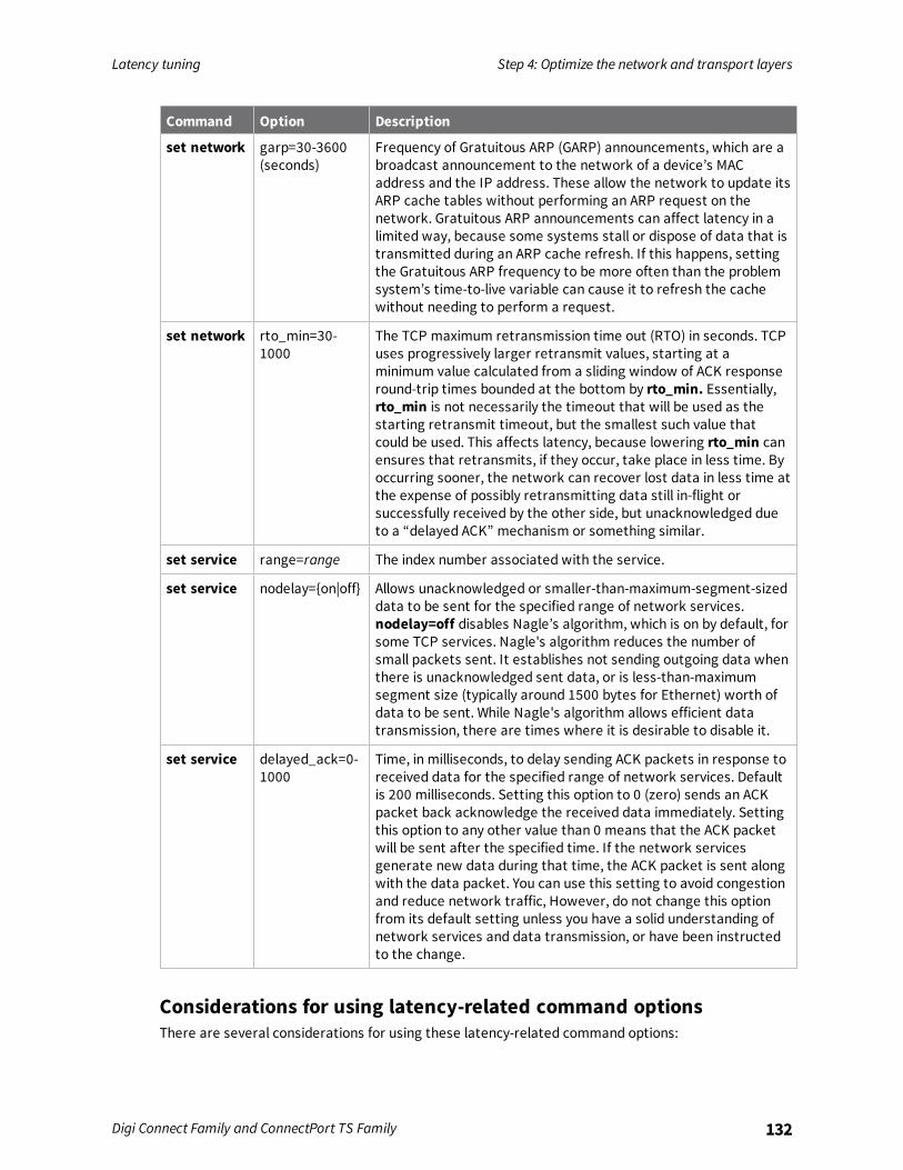
Latency tuning Step 4: Optimize the network and transport layers
Digi Connect Family and ConnectPort TS Family 132
Command Option Description
set network garp=30-3600(seconds)
Frequency of Gratuitous ARP (GARP) announcements, which are abroadcast announcement to the network of a device’s MACaddress and the IP address. These allow the network to update itsARP cache tables without performing an ARP request on thenetwork. Gratuitous ARP announcements can affect latency in alimited way, because some systems stall or dispose of data that istransmitted during an ARP cache refresh. If this happens, settingthe Gratuitous ARP frequency to be more often than the problemsystem’s time-to-live variable can cause it to refresh the cachewithout needing to perform a request.
set network rto_min=30-1000
The TCP maximum retransmission time out (RTO) in seconds. TCPuses progressively larger retransmit values, starting at aminimum value calculated from a sliding window of ACK responseround-trip times bounded at the bottom by rto_min. Essentially,rto_min is not necessarily the timeout that will be used as thestarting retransmit timeout, but the smallest such value thatcould be used. This affects latency, because lowering rto_min canensures that retransmits, if they occur, take place in less time. Byoccurring sooner, the network can recover lost data in less time atthe expense of possibly retransmitting data still in-flight orsuccessfully received by the other side, but unacknowledged dueto a “delayed ACK” mechanism or something similar.
set service range=range The index number associated with the service.
set service nodelay={on|off} Allows unacknowledged or smaller-than-maximum-segment-sizeddata to be sent for the specified range of network services.nodelay=off disables Nagle’s algorithm, which is on by default, forsome TCP services. Nagle's algorithm reduces the number ofsmall packets sent. It establishes not sending outgoing data whenthere is unacknowledged sent data, or is less-than-maximumsegment size (typically around 1500 bytes for Ethernet) worth ofdata to be sent. While Nagle's algorithm allows efficient datatransmission, there are times where it is desirable to disable it.
set service delayed_ack=0-1000
Time, in milliseconds, to delay sending ACK packets in response toreceived data for the specified range of network services. Defaultis 200 milliseconds. Setting this option to 0 (zero) sends an ACKpacket back acknowledge the received data immediately. Settingthis option to any other value than 0 means that the ACK packetwill be sent after the specified time. If the network servicesgenerate new data during that time, the ACK packet is sent alongwith the data packet. You can use this setting to avoid congestionand reduce network traffic, However, do not change this optionfrom its default setting unless you have a solid understanding ofnetwork services and data transmission, or have been instructedto the change.
Considerations for using latency-related command optionsThere are several considerations for using these latency-related command options:

Latency tuning Step 5: Optimize the application layer
Digi Connect Family and ConnectPort TS Family 133
n Changing the options from their defaults may violate RFCs.
n Decrementing the values for these options increases the amount of network activity. Forexample, there will be increased retransmissions.
n For a peer-to-peer application, you need to consider both sides of the connection and howoptions are set. For example, if the setting for the rto_min option for the Digi device is set to avalue that is less than the setting for the delayed_ack option for the other side of theconnection, then there will be a forced retransmission of every packet of data. For a master-slave application, this consideration does not apply.
Step 5: Optimize the application layerOptimizing the application layer may include, but is not limited to, these recommendations:
n Avoid having more than one application/network node generating time-sensitive traffic in thenetwork Have one traffic generator in a master-slave setup on the network.
n Avoid running other (management) applications, such as email, image or mp3 downloadingwhile time-sensitive traffic is running.
n Verify the application itself has timers that cause retransmissions of data.
n Use firewalls.
Specifications and certifications
This chapter provides hardware specifications, additional feature detail, and regulatory statementsand certifications for Digi devices.
Hardware specifications 135Wireless networking features 138Digi Connect and ConnectPort TS Family regulatory information and certifications 140
Digi Connect Family and ConnectPort TS Family 134

Specifications and certifications Hardware specifications
Digi Connect Family and ConnectPort TS Family 135
Hardware specificationsThis section provides the hardware specifications for all products in the Digi Connect and ConnectPortTS Family.For more detailed hardware specifications, see the Hardware Reference Manual and datasheet for yourDigi Connect and ConnectPort TS Family product. The specifications provided in this section apply toproducts that do not include a hardware reference manual.
Digi Connect ES specifications
Specification Value
Environmental Ambient temperature 0 to 55 C (32 to 130 F)
Relative humidity Relative humidity not to exceed 95% non-condensing over the temperature range from 4Cto 45C. Above 45C, constant absolute humidityshall be maintained.
Storage and transporttemperature
30 to 85 C (-122 to 185 F)
Altitude 2000 meters (6560 feet)
Serial Port Protection (ESD) Serial Port Protection (ESD): +15 kV human bodymodel
Powerrequirements
External 100-240V
Input frequency 50-60 Hz
Input current protection 2.0 A / 250 V(Time Lag) rated fuse
UL certified Yes
Surge protection n 4 kV burst (EFT)per EN61000-4-4
n 4 kV isolation input to output
n 2 kV surge per EN61000-4-5
Dimensions Length 23.5 cm (9.3 in)
Width 26.9 cm (10.6 in)
Depth 4.2 cm (2.1 in)
Weight 1.36 kg (3.00 lb)
RJ-45 pinoutPin assignments for the RJ-45 connector on the ConnectPort ES are as follows:

Specifications and certifications Hardware specifications
Digi Connect Family and ConnectPort TS Family 136
PinNumber
EIA-232Signal
01 RI
02 DSR
03 RTS
04 CGND
05 TxD
06 RxD
07 SGND
08 CTS
09 DTR
10 DCD
ConnectPort TS 8 specifications
Specification Value
Environmental Ambient temperature 0 to 60C3 (2 to 140F)
Relative humidity 5 to 95% (non-condensing)
Storage and transporttemperature
-40 to 85C (-40 to 185F)
Altitude 2000 meters (6560 feet)
Serial port protection (ESD) +15 kV human body model
Powerrequirements
DC power range 9-30V
Typical power consumptionDC Current @ 120 Vdc (mA)
6W (500mA@ 12Vdc)
Maximum powerconsumption(watts)
12W (1A @ 12Vdc)
Recommended powersupply input rating (watts)
17W (120 VAC @ .14A)External power supply provided with productpurchase
For units that have a 48VDC DC supply:13W (48VDC @ .25A)
UL certified Yes
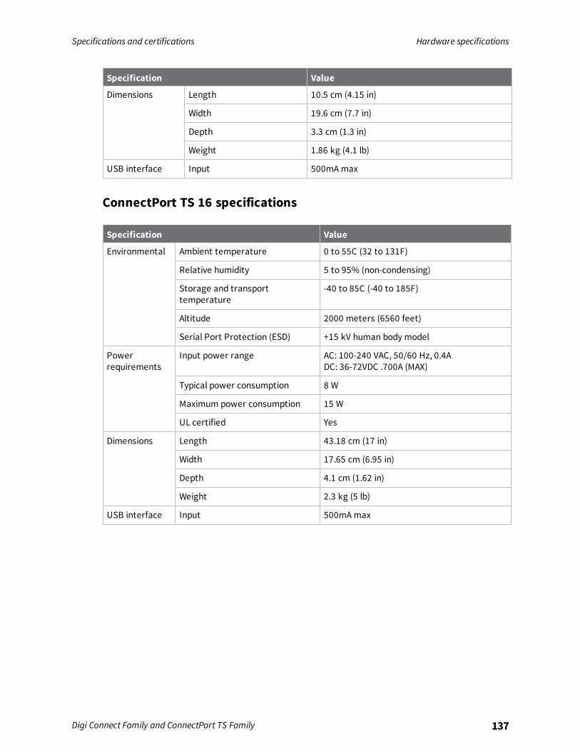
Specifications and certifications Hardware specifications
Digi Connect Family and ConnectPort TS Family 137
Specification Value
Dimensions Length 10.5 cm (4.15 in)
Width 19.6 cm (7.7 in)
Depth 3.3 cm (1.3 in)
Weight 1.86 kg (4.1 lb)
USB interface Input 500mAmax
ConnectPort TS 16 specifications
Specification Value
Environmental Ambient temperature 0 to 55C (32 to 131F)
Relative humidity 5 to 95% (non-condensing)
Storage and transporttemperature
-40 to 85C (-40 to 185F)
Altitude 2000 meters (6560 feet)
Serial Port Protection (ESD) +15 kV human body model
Powerrequirements
Input power range AC: 100-240 VAC, 50/60 Hz, 0.4ADC: 36-72VDC .700A (MAX)
Typical power consumption 8 W
Maximum power consumption 15 W
UL certified Yes
Dimensions Length 43.18 cm (17 in)
Width 17.65 cm (6.95 in)
Depth 4.1 cm (1.62 in)
Weight 2.3 kg (5 lb)
USB interface Input 500mAmax
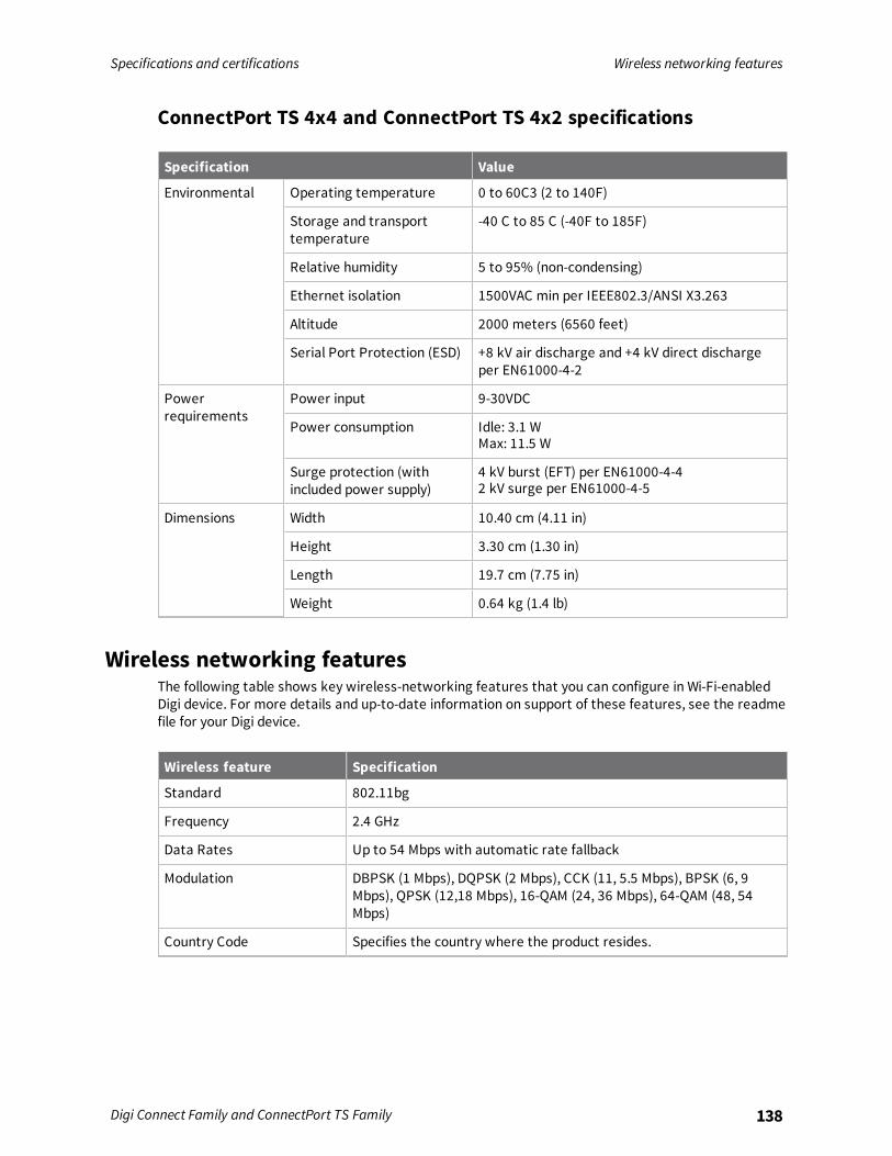
Specifications and certifications Wireless networking features
Digi Connect Family and ConnectPort TS Family 138
ConnectPort TS 4x4 and ConnectPort TS 4x2 specifications
Specification Value
Environmental Operating temperature 0 to 60C3 (2 to 140F)
Storage and transporttemperature
-40 C to 85 C (-40F to 185F)
Relative humidity 5 to 95% (non-condensing)
Ethernet isolation 1500VAC min per IEEE802.3/ANSI X3.263
Altitude 2000 meters (6560 feet)
Serial Port Protection (ESD) +8 kV air discharge and +4 kV direct dischargeper EN61000-4-2
Powerrequirements
Power input 9-30VDC
Power consumption Idle: 3.1 WMax: 11.5 W
Surge protection (withincluded power supply)
4 kV burst (EFT) per EN61000-4-42 kV surge per EN61000-4-5
Dimensions Width 10.40 cm (4.11 in)
Height 3.30 cm (1.30 in)
Length 19.7 cm (7.75 in)
Weight 0.64 kg (1.4 lb)
Wireless networking featuresThe following table shows key wireless-networking features that you can configure in Wi-Fi-enabledDigi device. For more details and up-to-date information on support of these features, see the readmefile for your Digi device.
Wireless feature Specification
Standard 802.11bg
Frequency 2.4 GHz
Data Rates Up to 54 Mbps with automatic rate fallback
Modulation DBPSK (1 Mbps), DQPSK (2 Mbps), CCK (11, 5.5 Mbps), BPSK (6, 9Mbps), QPSK (12,18 Mbps), 16-QAM (24, 36 Mbps), 64-QAM (48, 54Mbps)
Country Code Specifies the country where the product resides.

Specifications and certifications Wireless networking features
Digi Connect Family and ConnectPort TS Family 139
Wireless feature Specification
Network Mode n Open
n Infrastructure mode
n Ad-Hoc mode
Channel Can use automatic channel search-and-select or a user-configurablechannel number.
Service Set Identifier (SSID) A user-configurable SSID string or auto-connect option.
Wireless Security n Wi-Fi Protected Access (WPA/WPA2/802.11i)
n Wired Equivalent Privacy (WEP)
Authentication Options n Open
n Shared
n Wi-Fi Protected Access (WPA2—/802.11i)
n WPA/WPA2 with pre-shared key (WPA-PSK)
802.1x(WPA2—/802.11i)Authentication
n LEAP (WEP), PEAP, TTLS, TLS, EAP-FAST
n GTC, MD5, OTP, PAP, CHAP, MSCHAP, MSCHAPv2, TTLS-MSCHAPv2
Encryption n Temporal Key Integrity Protocol (TKIP)
n Counter mode CBC MAC Protocol (CCMP)
n Wired Equivalent Privacy (WEP)
n Use of encryption can be disabled
Network Key A shared key (ASCII or Hexadecimal) for WEP or WPA-PSK.
Username Specify the user name to use for 802.1x -based authentication (WPA).
Password Specify the password to use for 802.1x based authentication (WPA).
Ekahau Client Provides integrated support for Ekahau's Wi-Fi device-locationsolution. Ekahau offers a complete access point vendor-independentreal-time location system for wireless LAN devices that is capable ofpinpointing wireless LAN devices such as the Digi Connect products,laptops, PDAs, or other intelligent Wi-Fi enabled devices. The solutionprovides floor-, room- and door-level accuracy of up to 3.5 feet (1 m).The patented Ekahau positioning technology is based on simplesignal-strength calibration maps, and enables customers to fullyleverage an existing wireless LAN infrastructure without any need forproprietary hardware components.

Specifications andcertifications
Digi Connect and ConnectPort TS Family regulatory information andcertifications
Digi Connect Family and ConnectPort TS Family 140
Wireless feature Specification
Wireless Networking StatusFeatures
The following status information can be displayed for Wireless Digidevices.For more detailed descriptions, see Wi-Fi LAN Statistics.
Connection Status The status of the wireless network connection.
Network Mode The network mode currently in use:n Infrastructure mode
n Ad-Hoc mode
Data Transfer Rate The data transfer rate of the current connection.
Channel The wireless network channel currently in use.
SSID The selected SSID of the wireless network.
Wireless Security: Wi-FiProtected Access(WPA/WPA2/802.11i), WiredEquivalent Privacy (WEP)security and encryption
The status of the WEP/WPA/WPA2 security features, including theAuthentication Method currently in use and whether authentication isenabled or disabled.
Signal Strength A statistic that indicates the strength of the radio signal between 0and 100 percent.
Digi Connect and ConnectPort TS Family regulatory informationand certifications
This section documents Digi Connect and ConnectPort TS Family regulatory information andcertifications.

Specifications andcertifications
Digi Connect and ConnectPort TS Family regulatory information andcertifications
Digi Connect Family and ConnectPort TS Family 141
RF exposure statement
Digi Connect Wi-SP, Digi Connect Wi-EM, and Digi Connect Wi-METhe Digi Connect and ConnectPort TS Family wireless devices Digi Connect Wi-SP, Digi Connect Wi-EM,and Digi Connect Wi-ME comply with the RF exposure limits for humans as called out in RSS-102.These devices are exempt from RF evaluation based on its operating frequency of 2400 MHz, andeffective radiated power of 100 milliwatts. This would be less than the 3 watt requirement for amobile device (>20 cm separation) operating at 2400 MHz.
FCC certifications and regulatory information (USA only)n FCC Part 15 Class B
n Radio Frequency Interface (RFI) (FCC 15.105)
n Labeling Requirements FCC (15.19)
FCC part 15 Class AThese devices comply with part 15 of the FCC rules. Operation is subject to the following twoconditions: (1) These devices may not cause harmful interference, and (2) These devices must acceptany interference received, including interference that may cause harmful operation.
Radio Frequency Interface (RFI) (FCC 15.105)This device has been tested and found to comply with the limits for Class B digital devices pursuant toPart 15 Subpart B, of the FCC rules. These limits are designed to provide reasonable protectionagainst harmful interference in a residential environment. This equipment generates, uses, and canradiate radio frequency energy, and if not installed and used in accordance with the instructionmanual, may cause harmful interference to radio communications. However, there is no guaranteethat interference will not occur in a particular installation. If this equipment does cause harmfulinterference to radio or television reception, which can be determined by turning the equipment offand on, the user is encouraged to try and correct the interference by one or more of the followingmeasures:
n Reorient or relocate the receiving antenna.
n Increase the separation between the equipment and receiver.
n Connect the equipment into an outlet on a circuit different from that to which the receiver isconnected.
n Consult the dealer or an experienced radio/TV technician for help.
Labeling Requirements FCC (15.19)This device complies with Part 15 of FCC rules. Operation is subject to the following two conditions: (1)this device may not cause harmful interference, and (2) this device must accept any interferencereceived, including interference that may cause undesired operation.If the FCC ID is not visible when installed inside another device, then the outside of the device intowhich the module is installed must also display a label referring to the enclosedmodule FCC ID.
Modifications (FCC 15.21)Changes or modifications to this equipment not expressly approved by Digi may void the user’sauthority to operate this equipment.

Specifications andcertifications
Digi Connect and ConnectPort TS Family regulatory information andcertifications
Digi Connect Family and ConnectPort TS Family 142
Cables (FCC 15.27)Shielded cables must be used to remain within the Class A limitations.
Industry Canada (IC) certificationsThis digital apparatus does not exceed the Class A limits for radio noise emissions from digitalapparatus set out in the Radio Interference Regulations of the Canadian Department ofCommunications.Le present appareil numerique n'emet pas de bruits radioelectriques depassant les limites applicablesaux appareils numeriques de la class A prescrites dans le Reglement sur le brouillage radioelectriqueedicte par le ministere des Communications du Canada.
International EMC (Electromagnetic Emmissions/Immunity/Safety)standardsThese products comply with the requirements of following ElectromagneticEmissions/Immunity/Safety standards. There are no user-serviceable parts inside the product.Contact your Digi representative for repair information.
Product Emissions Immunity Safety
Digi Connect ES n EN60601-1-2:2001
n EN55011:1998
n EN55022:1998
n AS/NZS CISPR22: 2002
n ICES-003, Issue3:1997
n FCC Part 15Subpart B ClassA
EN55024:1998 n CAN/CSA C22.2No. 60950-1-3
n UL60950-1
n IE60950-1
n IEC60601-1
ConnectPort TS 8ConnectPort TS 8 MEI
n EN55022
n AS/NZS CISPR22: 2004
n ICES-003, Issue3:1997
n FCC Part 15Subpart B ClassA
EN55024 n UL60950-1
n IEC60950-1
n CAN/CSA C22.2No 60950-1-3
n EN/IEC 62368-1
n CSA/UL 62368-1:2014

Specifications andcertifications
Digi Connect and ConnectPort TS Family regulatory information andcertifications
Digi Connect Family and ConnectPort TS Family 143
Product Emissions Immunity Safety
ConnectPort TS 16ConnectPort TS 16 MEI
n EN55022:2006
n AS/NZS CISPR22:2006
n ICES-003 Iss.4:2004
n FCC P15subpart B ClassA
EN55024:1998+A1:2001+A2:2003
n EN/IEC60950-1
n UL 60950-1
n CUL 60950-1-03
n EN/IEC 62368-1
n CSA/UL 62368-1:2014
ConnectPort TS 4x4ConnectPort TS 4x2
n CE
n FCC Part 15subpart B, ClassA
n AS/NZS CISPR22
n EN55022, ClassA
EN55024 n UL 60950-1
n CSA 22.2 No.60950
n EN60950
Troubleshooting
This section provides information on resources and processes available for troubleshooting your Digidevice.
Troubleshooting resources 145System status LEDs 145
Digi Connect Family and ConnectPort TS Family 144

Troubleshooting Troubleshooting resources
Digi Connect Family and ConnectPort TS Family 145
Troubleshooting resourcesUse the troubleshooting information in this section to resolve your issue with your Digi device. If youcannot resolve the issue using the information in this section, there are several resources you can useto resolve your issue on the Digi Support site.To resolve a problem from the Digi Support site:
1. Visit Digi’s Knowledge Base at knowledge.digi.com/ and search for articles related to yoursituation.
2. Visit our support forums at www.digi.com/support/forum/ and search for posts from otherusers with similar situations.
3. Complete a support ticket via email to [email protected] will need to create a user account if one is not already set up.
4. To obtain direct assistance for your issue within a four hour time period, log in to your paidsupport account (or create one) at www.digi.com/support, and submit a support ticket.
System status LEDsDigi devices have several LEDs that indicate system status, link integrity, and link activity.
Digi Connect Family LEDsDigi Connect LEDs provide information on port activity, diagnostics, and Ethernet activity.
Digi Connect SPDigi Connect SP has three LEDs: Ethernet Link and Ethernet Activity, which are connected directly tothe hardware; and the Power LED, which is software programmable.
LED/button Color and Light Pattern Description
Ethernet Link LED Off Ethernet link is not powered or down.
Solid green Ethernet link is up.
Ethernet ActivityLED
Blinking yellow Ethernet traffic is on the link.

Troubleshooting System status LEDs
Digi Connect Family and ConnectPort TS Family 146
LED/button Color and Light Pattern Description
Power LED Red (labeled PWR) This LED is software programmable. By default,this LED indicates power (and is therefore alwayson).
Digi Connect WI-SPDigi Connect Wi-SP has three LEDs: Wi-Fi Link andWi-Fi Activity, which are connected directly to thehardware; and the Power LED, which is software programmable.
LED/button Color and Light Pattern Description
Wi-Fi Link StatusLED
Solid green Unit is associated with an access point.
Green, blinking slowly Unit is in ad hoc mode.
Green, blinking quickly Unit is scanning for a network
Wi-Fi ActivityStatus LED
Solid yellow Bad initialization
Off The Wi-Fi link is idle.
Blinking yellow Traffic is on the Wi-Fi link.
Power LED Red (labeled PWR) This LED is software programmable. By default,this LED indicates power (and is therefore alwayson).
Digi Connect METhe Digi Connect ME module has two LEDs that are located near the upper corners of the Ethernetport (see the following figure).
Note The LEDs are the same for a module with or without a JTAG connector.

Troubleshooting System status LEDs
Digi Connect Family and ConnectPort TS Family 147
LED/button Color and Light Pattern Description
Ethernet Link LED Solid yellow Ethernet link is up.
Ethernet ActivityLED
Blinking green Ethernet traffic is on the link.
Digi Connect Wi-ME
LED/buttonColor and LightPattern Description
Wi-Fi Link Status LED Solid yellow Unit is associated with an access point.
Yellow, blinkingslowly
Unit is in ad hoc mode.
Yellow, blinkingquickly
Unit is scanning for a network.
Wi-Fi Activity Status LED Off The Wi-Fi link is idle.
Blinking green Wi-Fi traffic is on the link.
Digi Connect EM and Digi Connect Wi-EMDigi Connect EM and Digi Connect Wi-EM modules provide two hardware options for LEDs, with orwithout on board LED array. The integration kit provides predefined LED behavior. With thedevelopment kit, your implementation determines some LED behavior. See the following table formore information.
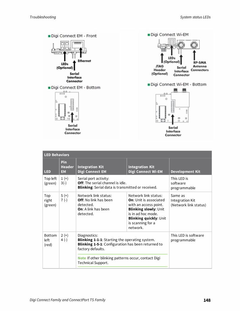
Troubleshooting System status LEDs
Digi Connect Family and ConnectPort TS Family 148
LED Behaviors
LED
PinHeaderEM
Integration KitDigi Connect EM
Integration KitDigi Connect Wi-EM Development Kit
Top left(green)
1 (+)3(-)
Serial port activity:Off: The serial channel is idle.Blinking: Serial data is transmitted or received.
This LED issoftwareprogrammable
Topright(green)
5 (+)7 (-)
Network link status:Off: No link has beendetected.On: A link has beendetected.
Network link status:On: Unit is associatedwith an access point.Blinking slowly: Unitis in ad hoc mode.Blinking quickly: Unitis scanning for anetwork.
Same asIntegration Kit(Network link status)
Bottomleft(red)
2 (+)4 (-)
Diagnostics:Blinking 1-1-1: Starting the operating system.Blinking 1-5-1: Configuration has been returned tofactory defaults.
Note If other blinking patterns occur, contact DigiTechnical Support.
This LED is softwareprogrammable

Troubleshooting System status LEDs
Digi Connect Family and ConnectPort TS Family 149
LED Behaviors
LED
PinHeaderEM
Integration KitDigi Connect EM
Integration KitDigi Connect Wi-EM Development Kit
Bottomright(yellow)
6 (+)8 (-)
Blinking: Network data is transmitted or received This LED issoftwareprogrammable
Digi Connect 48 SB and Digi Connect 4/8 SB with switch

Troubleshooting System status LEDs
Digi Connect Family and ConnectPort TS Family 150
LED/buttonColor and LightPattern Description
Ethernet Uplink LED Solid green Ethernet Uplink connection is up but no traffic ison the line.
Blinking green Traffic is on the Ethernet Uplink connection.
Off Ethernet Uplink connection is disconnected.
Ethernet Switch LEDs Solid green Ethernet Switch connection is up but there is noactivity on the line.
Blinking green Ethernet activity is on the Ethernet Switchconnection
Off Ethernet Switch connection is not in use.
Serial LED Solid green Serial connection is up but no traffic is on theline.
Blinking green Serial connection is up and traffic is on the serialport.
Off Serial connection is not in use
Find Me/Locator LED Blinking amber Use the LED as an aid in finding a specific deviceamong a group of devices. You can turn LED on oroff from the Digi device’s command line and webinterfaces.From the command line, issue thefindme blink={on|off} command.From the web interface, go to Administration >Activate Find Me LED. Once the LED is enabled,the menu item changes to Stop Find Me LEDwhich you can use to turn off the LED.
Off Find Me LED is deactivated.
Power Green Power is on.
Off Power is off.

Troubleshooting System status LEDs
Digi Connect Family and ConnectPort TS Family 151
ConnectPort TS Family Products
ConnectPort TS 4x4
LED/buttonColor and LightPattern Description
Power LED Solid Green Power on.
Fuse Good LED Solid Green Power on and the fuse is good.If this LED is not illuminated when power isapplied, the fuse is blown and needs to bereplaced.

Troubleshooting System status LEDs
Digi Connect Family and ConnectPort TS Family 152
LED/buttonColor and LightPattern Description
Diag LED Amber Blinks during product initialization and factoryreset, using the light patterns below. This LEDshould never blink during normal operation. If itblinks constantly, contact Digi Technical Support.
1-1-1 blinkingamber
Initializing firmware.
1-5-1 blinkingamber
Device configuration has been restored to itsfactory defaults.
Other blinkingamber
Contact Digi Technical Support.
Solid amber Device is powered on and ready for operation.
C1 & C2 LEDs Green These LEDs are provided for use by custom Linuxapplications running on the unit.
Reset button N/A Performs equivalent of a power-cycle.
Serial TX Yellow Serial port is transmitting data.
Serial RX Green Serial port is receiving data.
Ethernet Link LED Solid green Ethernet link is up. Will light solid green when anactive LAN connection is plugged into theEthernet port.
Ethernet Activity LED Blinking yellow Blinks when active traffic is on the LANconnection.
ConnectPort TS 8 and ConnectPort TS 8 MEI

Troubleshooting System status LEDs
Digi Connect Family and ConnectPort TS Family 153
ConnectPort TS 16 and ConnectPort TS 16-MEI
LED/buttonColor and LightPattern Description
Power LED Solid Green Power on.
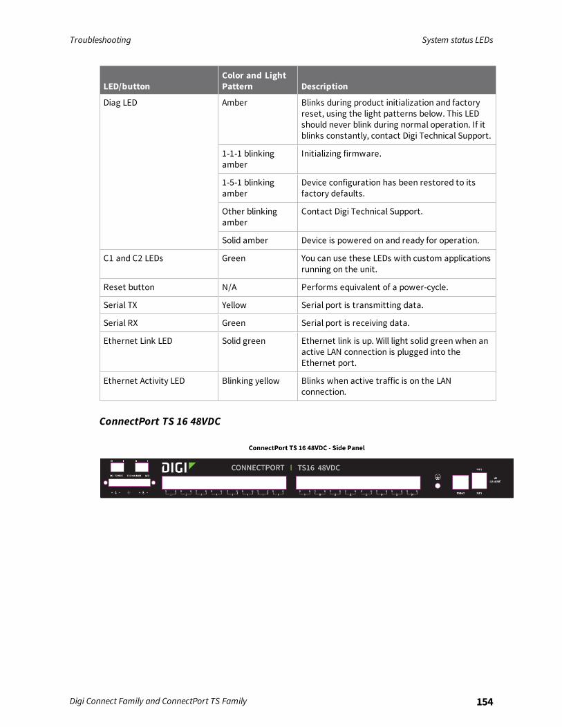
Troubleshooting System status LEDs
Digi Connect Family and ConnectPort TS Family 154
LED/buttonColor and LightPattern Description
Diag LED Amber Blinks during product initialization and factoryreset, using the light patterns below. This LEDshould never blink during normal operation. If itblinks constantly, contact Digi Technical Support.
1-1-1 blinkingamber
Initializing firmware.
1-5-1 blinkingamber
Device configuration has been restored to itsfactory defaults.
Other blinkingamber
Contact Digi Technical Support.
Solid amber Device is powered on and ready for operation.
C1 and C2 LEDs Green You can use these LEDs with custom applicationsrunning on the unit.
Reset button N/A Performs equivalent of a power-cycle.
Serial TX Yellow Serial port is transmitting data.
Serial RX Green Serial port is receiving data.
Ethernet Link LED Solid green Ethernet link is up. Will light solid green when anactive LAN connection is plugged into theEthernet port.
Ethernet Activity LED Blinking yellow Blinks when active traffic is on the LANconnection.
ConnectPort TS 16 48VDC